user instructions - flowserve · 2020-01-02 · mx/qx hart field unit fcd lmenim2340-01 – 06/16 6...
TRANSCRIPT
USER INSTRUCTIONS
Installation Operation
Maintenance
Experience In Motion
MX/QX HART Field UnitFCD LMENIM2340-01 – 06/16
MX/QX HART Field Unit FCD LMENIM2340-01 – 06/16
2
Contents1 Introduction 61.1 Purpose 61.2 How to Use This Manual 61.3 User Safety 71.4 User Knowledge 71.5 MX/QX HART System Capabilities and Features 71.5.1 General Network Specification 82 System Components and Installation 92.1 Introduction 92.2 Hardware 92.2.1 MX/QX Electronic Actuators 92.2.2 MX/QX HART Interface Board 112.2.3 Network Host 112.2.4 Network Cable 112.2.5 Typical HART Network Configuration 112.3 Network Cabling Topologies 122.4 Site and Network Cable Preparation 132.4.1 Site Preparation 132.4.2 Network Cable Preparation 132.4.2.1 Network Cable Connection to the MX/QX HART Unit 132.5 MX/QX HART Device Installation and Setup 142.5.1 MX/QX HART Device Installation 142.5.2 MX/QX HART Device Setup 142.6 Installation Verification 162.6.1 Network Cabling Installation Verification 162.6.2 MX/QX HART Device Installation Verification 162.7 Configuration Confirmation 172.7.1 Checking Connections 172.7.2 View Settings 172.7.3 Checking the Normal Display 182.8 MX/QX HART Device Description and Device Type Manager Files 183 Software 193.1 HART Protocol 193.2 HART Parameters 193.2.1 Analog Input Ratings 193.2.2 Field Device Status 203.3 Dynamic Variables 203.4 Device Variables 203.4.1 Supported Device Variables 203.4.2 Device Variable Mapping 213.4.3 Device Variable Units 213.5 Supported HART Commands 223.5.1 Universal Commands 22 3.5.1.1 Command 48 Data 243.5.2 Common Commands 293.5.3 Burst Messages 333.5.3.1 Update Periods 333.5.3.2 Commands Supported for Burst Message 343.5.3.3 Configuring a Device for Burst Mode Operation 343.5.3.4 Burst Message Trigger Mode 353.5.3.5 Burst Trigger Mode 35
3
MX/QX HART Field Unit FCD LMENIM2340-01 – 06/16
flowserve.com
Contents (Continued)
3.5.4 Event Notification 353.5.4.1 Configuring Event Notification 363.5.4.2 Handling of Event Notifications 373.5.4.3 Update Periods 373.6 Device-Specific Commands 373.6.1 Remote Configuration Mode 373.6.2 Partial Stroke Test 393.6.3 Actuator Commands 413.7 Calibration 423.7.1 Loop Current Trim Procedure 423.7.2 Re-range Procedure 453.7.3 Analog Signal to Primary Variable Process Flow 474 Associated Documents 495 How to Order Parts 50Appendix A – Wiring Diagrams 51Appendix B – HART Data Formats 52Appendix C – Enumeration and Bit Field Tables 52-55Appendix D – Setting Data and Time 56Appendix E – Command Response Codes 56-67
MX/QX HART Field Unit FCD LMENIM2340-01 – 06/16
4
FiguresFigure 2.1a – MX-05 Actuator and Figure 2.1b – QX-05 Actuator 10Figure 2.2 – Typical HART System With a DCS Host 11Figure 2.3 – Point-to-Point Topology (Host Powered) 12Figure 2.4 – Point-to-Point Topology (Loop Powered) 12Figure 2.5 – Multi-drop Topology (Host Powered) 12Figure 2.6 – Multi-drop Topology (Loop Powered) 13Figure 2.7 – Connecting Network Cable to MX/QX Terminal Block 14Figure 2.8 – MX/QX HART Setup Sequence 15Figure 2.9 – MX/QX HART View Settings Sequence 17Figure 2.10 – Normal Display 18Figure 3.1 – Device Variable Mapping Setup 21Figure 3.2 – Device Variable Units 22Figure 3.3 – HART Diagnostics Data 28Figure 3.4 – Burst Messages 34Figure 3.5 – Trigger Mode 1 “Windowed” 35Figure 3.6 – Event Notification 36Figure 3.7 – Event Mask 36Figure 3.8 – Remote Configuration Mode 37Figure 3.9 – Analog Signal to Primary Variable Process Flow 48Figure 5.1 – Device Variable Status Byte Format 53
5
MX/QX HART Field Unit FCD LMENIM2340-01 – 06/16
flowserve.com
TablesTable 2.1a – MX Actuator Components and Table 2.1b – QX Actuator Components 10Table 3.1 – HART Parameters 19Table 3.2 – Analog Input Ratings 19Table 3.3 – Field Device Status 20Table 3.4 – Supported Dynamic Variables 20Table 3.5 – Supported Device Variables 20Table 3.6 – Mapping of Device Variables to Dynamic Variables 21Table 3.7 – HART Universal Commands 22Table 3.8 – HART Defined Status Bits 25Table 3.9 – MX/QX Defined Status Bits 26Table 3.10 – Common Commands 29Table 3.11 – Trigger Source for Burst Message Commands 35

MX/QX HART Field Unit FCD LMENIM2340-01 – 06/16
6
1 Introduction
1.1 PurposeThis manual explains how to install and operate the MX/QX HART field unit. Actuators containing the HART field unit may be connected by a standard instrumentation twisted-pair cable to form a HART communication system network. The HART network employs a bi-directional communication protocol, operating at 1200 bits/sec, that provides data access between intelligent actuators and host control/monitoring systems. In addition to a digital signal, the network simultaneously provides a 4-20 mA analog signal that is proportional to the field unit’s primary measured value. This system allows a host system such as a distributed control system (DCS) to control and monitor the actuators, including the acquisition of status and alarm data from each MX/QX.
1.2 How to Use This ManualEach section provides the MX/QX HART user with information on installing and operating the MX/QX HART field unit.
Section Title Description
1 Introduction Details user safety and knowledge requirements, system capabilities and features.
2 System Components Focuses on the description of the HART system hardware and software components.
3 Installation and Configuration Provides details for installing and configuring a field unit.
4 Associated Documents Provides a list of documents on related subjects for additional MX/QX and HART system information.
5 How to Order Parts This section provides part numbers and ordering contact information.
Appendix A Wiring Diagram Detail wiring connections to the MX/QX field unit.
Appendix B HART Data Formats Listing of HART parameters and descriptions.
Appendix C Enumeration and Bit Field Tables Explains field device bit masking information.
Appendix D Setting Date and Time Defines real-time clock configuration settings.
Appendix E Command Response Codes Listing of response codes for all universal and common HART commands.

7
MX/QX HART Field Unit FCD LMENIM2340-01 – 06/16
flowserve.com
1.3 User SafetySafety notices in this manual detail precautions the user must take to reduce the risk of personal injury and damage to the equipment. The user must read and be familiar with these instructions before attempting installation, operation, or maintenance. Failure to observe these precautions could result in serious bodily injury, damage to the equipment, warranty void, or operational difficulty. User must follow local and state safety regulations.
Safety notices are presented in this manual in three forms:
c WARNING: Refers to personal safety. Alerts the user to potential danger. Failure to follow warning notices could result in personal injury or death.
a CAUTION: Directs the user’s attention to general precautions that, if not followed, could result in personal injury and/or equipment damage.
NOTE: Highlights information critical to the user’s understanding of the operator’s installation and operation.
1.4 User KnowledgeIt is recommended that the user read this manual in its entirety before the MX/QX HART equipped actuator is installed and operated.
The user needs to have a fundamental knowledge of electronics and microprocessor concepts. An understanding of valve actuators and digital control systems is beneficial to the field unit user. Refer to the Glossary for terms used throughout this manual.
The following websites have documents on HART and electric actuators: www.hartcomm.org and www.flowserve.com
For HART technology and cabling information, refer to the following documents:
HART Communication Protocol Specification: HCF_SPEC-13HART Communication FSK Physical Layer Specification: HCF_SPEC-54HART Communication Command Summary Specification: HCF_SPEC-99HART Communication Universal Command Specification: HCF_SPEC-127HART Communication Common Practice Command Specification: HCF_SPEC-151HART Communication Common Tables: HCF_SPEC-183
1.5 MX/QX HART System Capabilities and FeaturesLimitorque’s HART field unit conforms to the HART Communication Protocol Specification (Document HCF_SPEC-13). The device is suitable for use on point-to-point and multi-drop network topologies. The communication system theoretically supports up to 26 actuators connected in a multi-drop network.
The MX/QX HART field unit fits in the actuator in the sealed electrical housing. Adjustments to the MX/QX HART settings must be made from the configuration SETUP menu.
The MX/QX HART field unit may command its actuator to:
Open Stop Close Move to a set position Perform an emergency shutdown operation Read and control relays Perform partial stroke test Monitor analog inputs and position Monitor modes and alarms
MX/QX HART Field Unit FCD LMENIM2340-01 – 06/16
8
Commands to the unit come over the network from the host system, which may be:
• Personal Computer (PC)• Distributed Control System (DCS)• Programmable Logic Controller (PLC)• Field Device Tool (FDT) w/Device Type Manager (DTM)• Some other microprocessor-based device
A HART field device is an intelligent device within the actuator that can send multiple digital device variables to the control system over a 4-20 mADC analog signal loop. The device provides control and self-test capabilities, which allow abnormal conditions to be easily and immediately identified before an unplanned shutdown occurs.
Additional features and capabilities are:
• The system reduces the cost of wiring and installation – existing wiring and multi-drop connections can be used. • The devices are interoperable – devices from different suppliers can communicate with one another on the same
network.
1.5.1 General Network Specification
System Specifications:
Communications using the HART Communication Foundation Protocol
Network Specificationss:
• Point-to-point and multi-drop topologies • Master/slave communication• Simultaneous 1200 bps digital communication without 4-20 mADC signal interruption• Up to two masters per network (primary and secondary)• Burst mode for continuous message broadcasting
MX/QX HART Unit Specification:
The field unit mounts in the actuator and is software-controlled in order to allow functionality of:
• Dynamic Variables PV, SV, QV and TV• Device Variables: Position Setpoint, Measured Position, Torque, Motor Temperature and Compartment Temperature• Network Communication• Device-Specific Commands
System Host Specifications:
The HART master is the network system host, and can be a personal computer (PC), distributed control system (DCS), programmable logic controller (PLC), or another microprocessor-based device. The HART protocol allows for up to two masters (primary and secondary) per network loop. Secondary masters, such as handheld communicators, can be used without interrupting communications between the primary master and field devices.
9
MX/QX HART Field Unit FCD LMENIM2340-01 – 06/16
flowserve.com
2 System Components and Installation
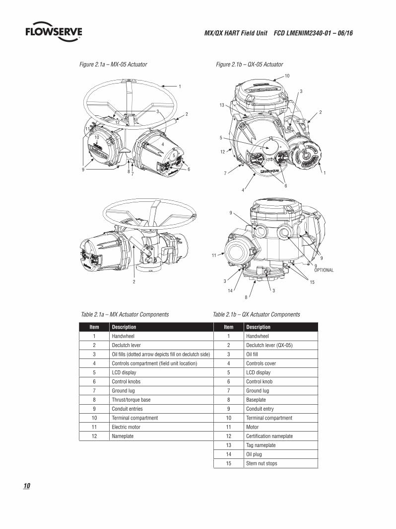
2.1 IntroductionThis section is an overview of the components used in the HART system and their installation. The MX/QX HART unit is installed in the MX or QX actuator, as shown in Figures 2.1 and 2.2. The network cable connects to the HART unit at the actuator terminal block. The network cable connects to the distributed control system, which usually acts as the host.
2.2 Hardware
2.2.1 MX/QX Electronic Actuators
The MX/QX actuators control the opening and closing of valves. The MX is a multi-turn valve, while the QX is a quarter-turn valve actuator. Both actuators are designed for operation of ON-OFF and modulating valve applications.
The MX/QX features include the following:
• Non-intrusive setup• Separately sealed terminal compartment• Patented absolute encoder for valve position sensing (no battery required)• Graphical LCD for indication and calibration• Sophisticated electronic control, monitoring, and diagnostic capabilities with patented LimiGard™ technology
NOTE: Recommended storage procedures for the MX are detailed in Bulletin LMENIM2306, MX Maintenance and Spare Parts Manual. QX procedures are detailed in Bulletin LMENIM3306, QX Maintenance and Spare Parts Manual. Failure to comply with recommended procedures will void the warranty. For longer-term storage, contact Limitorque for procedure and recommendations.
MX/QX HART Field Unit FCD LMENIM2340-01 – 06/16
10
Figure 2.1a – MX-05 Actuator Figure 2.1b – QX-05 Actuator
2
1
2 3
7 8
4
5
11 12
10
6 9
13
12
3
1
4 6
10
2
7
5
9
9
8
15
9OPTIONAL
3
14
11
3
Table 2.1a – MX Actuator Components Table 2.1b – QX Actuator Components
Item Description Item Description
1 Handwheel 1 Handwheel
2 Declutch lever 2 Declutch lever (QX-05)
3 Oil fills (dotted arrow depicts fill on declutch side) 3 Oil fill
4 Controls compartment (field unit location) 4 Controls cover
5 LCD display 5 LCD display
6 Control knobs 6 Control knob
7 Ground lug 7 Ground lug
8 Thrust/torque base 8 Baseplate
9 Conduit entries 9 Conduit entry
10 Terminal compartment 10 Terminal compartment
11 Electric motor 11 Motor
12 Nameplate 12 Certification nameplate
13 Tag nameplate
14 Oil plug
15 Stem nut stops
11
MX/QX HART Field Unit FCD LMENIM2340-01 – 06/16
flowserve.com
2.2.2 MX/QX HART Interface Board
The MX/QX HART field unit interface board is installed in the actuator controls compartment (Figures 2.1 & 2.2 and Tables 2.1 & 2.2). This unit permits the actuator to be controlled by a DCS or other network host over the HART network.
The following commands and feedback information are transmitted through this unit:
• OPEN, CLOSE and STOP commands• ESD (Emergency Shutdown) commands• Partial Stroke Test commands• Unit output torque (0-100% rating)• Go-to-position commands• Actuator status, alarm and diagnostic messages• User analog input feedback
2.2.3 Network Host
The HART network is a master/slave communication protocol. Communication to each slave (MX/QX field device) is initiated by a master (system host device). Two masters can connect to each HART loop. Normally, the primary master is a DCS, PLC, or PC. If desired, a handheld communicator or PC can serve as the secondary master.
2.2.4 Network Cable
Network cabling should be in accordance with the HART Communication Foundation guidelines. In general, wiring for HART devices is the same as for conventional 4-20 mA instrumentation. It is recommended to use individually shielded twisted pair cable. The minimum conductor size is 0.51mm diameter (#24 AWG) for cable runs less than 1500 meters (5000 ft.), and 0.81mm diameter (#20 AWG) for distances up to the 3000 meter (10 000 ft.) theoretical limit for HART communication. Please note that the electrical characteristics of the cable, especially capacitance, and the number of network field devices can affect the maximum allowable cable length.
To prevent signal loop interference, tie all cable shields together and ground at only one point.
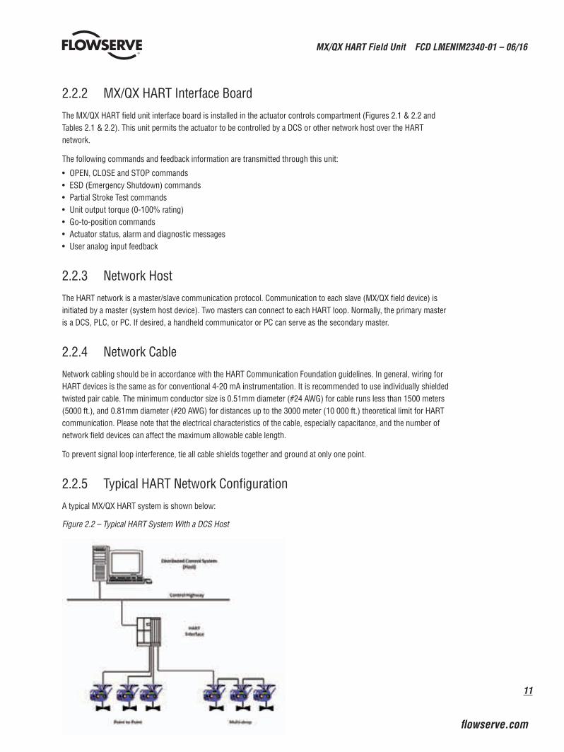
2.2.5 Typical HART Network Configuration
A typical MX/QX HART system is shown below:
Figure 2.2 – Typical HART System With a DCS Host
MX/QX HART Field Unit FCD LMENIM2340-01 – 06/16
12
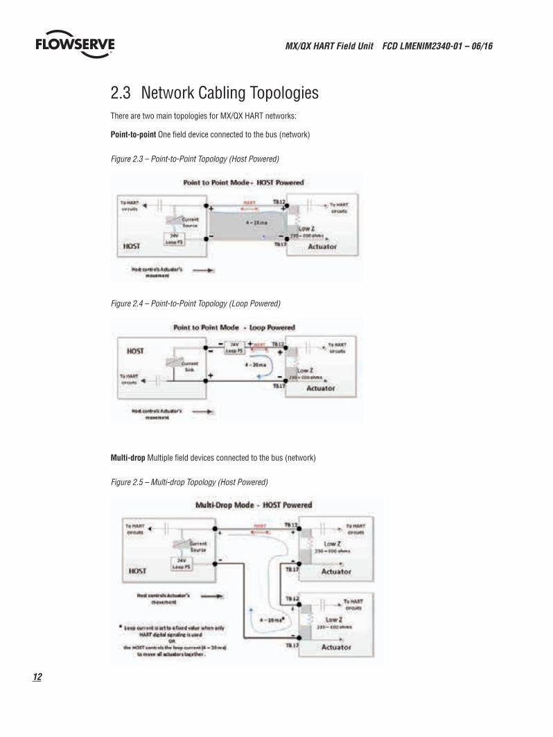
2.3 Network Cabling TopologiesThere are two main topologies for MX/QX HART networks:
Point-to-point One field device connected to the bus (network)
Figure 2.3 – Point-to-Point Topology (Host Powered)
Figure 2.4 – Point-to-Point Topology (Loop Powered)
Multi-drop Multiple field devices connected to the bus (network)
Figure 2.5 – Multi-drop Topology (Host Powered)
13
MX/QX HART Field Unit FCD LMENIM2340-01 – 06/16
flowserve.com
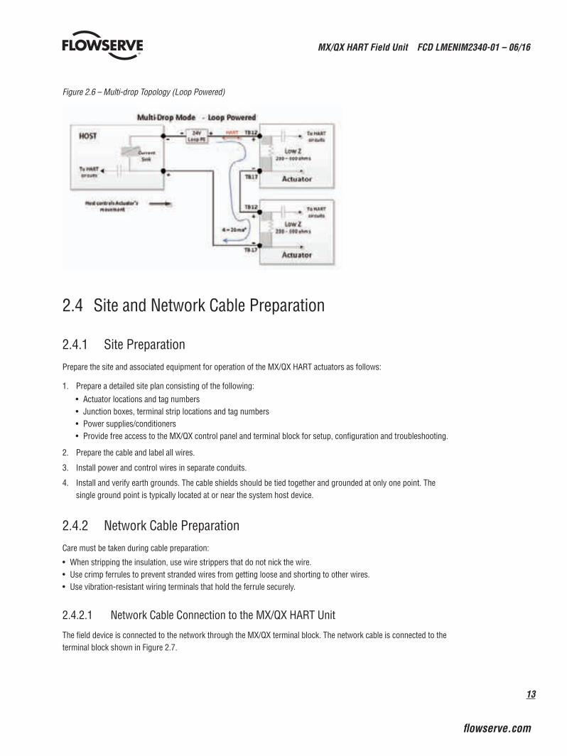
Figure 2.6 – Multi-drop Topology (Loop Powered)
2.4 Site and Network Cable Preparation
2.4.1 Site Preparation
Prepare the site and associated equipment for operation of the MX/QX HART actuators as follows:
1. Prepare a detailed site plan consisting of the following:
• Actuator locations and tag numbers• Junction boxes, terminal strip locations and tag numbers• Power supplies/conditioners• Provide free access to the MX/QX control panel and terminal block for setup, configuration and troubleshooting.
2. Prepare the cable and label all wires.
3. Install power and control wires in separate conduits.
4. Install and verify earth grounds. The cable shields should be tied together and grounded at only one point. The single ground point is typically located at or near the system host device.
2.4.2 Network Cable Preparation
Care must be taken during cable preparation:
• When stripping the insulation, use wire strippers that do not nick the wire.• Use crimp ferrules to prevent stranded wires from getting loose and shorting to other wires.• Use vibration-resistant wiring terminals that hold the ferrule securely.
2.4.2.1 Network Cable Connection to the MX/QX HART Unit
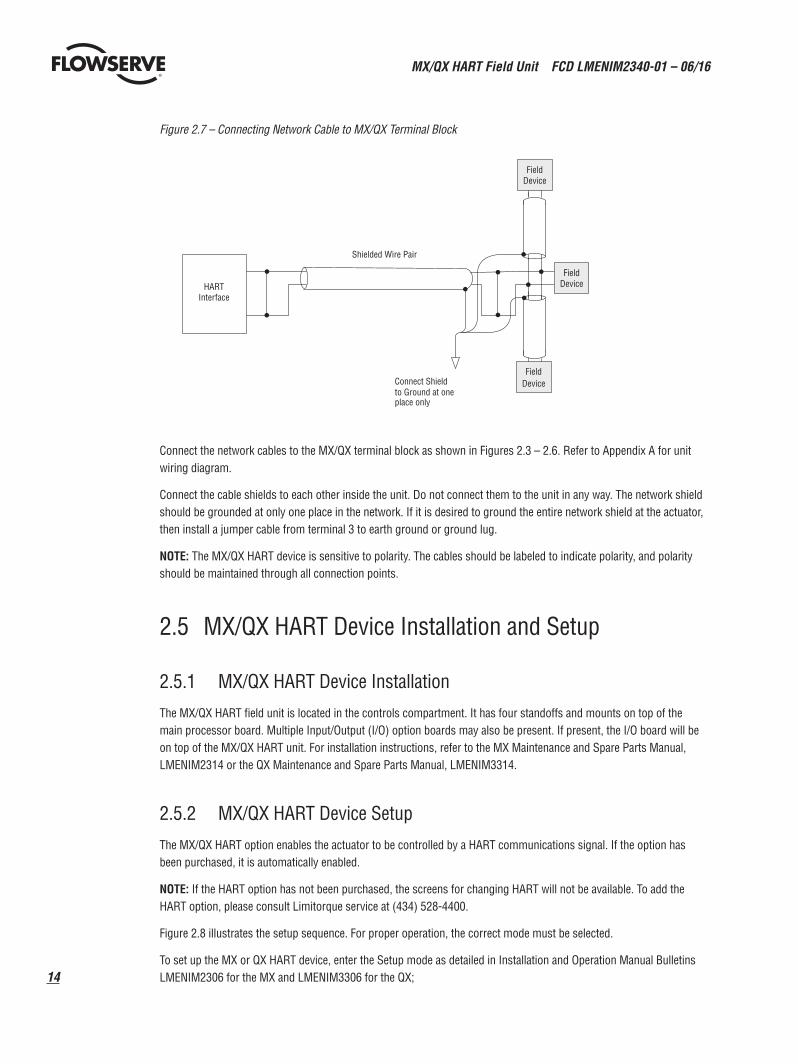
The field device is connected to the network through the MX/QX terminal block. The network cable is connected to the terminal block shown in Figure 2.7.
MX/QX HART Field Unit FCD LMENIM2340-01 – 06/16
14
Figure 2.7 – Connecting Network Cable to MX/QX Terminal Block
HARTInterface
Shielded Wire Pair
Connect Shieldto Ground at oneplace only
FieldDevice
FieldDevice
FieldDevice
Connect the network cables to the MX/QX terminal block as shown in Figures 2.3 – 2.6. Refer to Appendix A for unit wiring diagram.
Connect the cable shields to each other inside the unit. Do not connect them to the unit in any way. The network shield should be grounded at only one place in the network. If it is desired to ground the entire network shield at the actuator, then install a jumper cable from terminal 3 to earth ground or ground lug.
NOTE: The MX/QX HART device is sensitive to polarity. The cables should be labeled to indicate polarity, and polarity should be maintained through all connection points.
2.5 MX/QX HART Device Installation and Setup
2.5.1 MX/QX HART Device Installation
The MX/QX HART field unit is located in the controls compartment. It has four standoffs and mounts on top of the main processor board. Multiple Input/Output (I/O) option boards may also be present. If present, the I/O board will be on top of the MX/QX HART unit. For installation instructions, refer to the MX Maintenance and Spare Parts Manual, LMENIM2314 or the QX Maintenance and Spare Parts Manual, LMENIM3314.
2.5.2 MX/QX HART Device Setup
The MX/QX HART option enables the actuator to be controlled by a HART communications signal. If the option has been purchased, it is automatically enabled.
NOTE: If the HART option has not been purchased, the screens for changing HART will not be available. To add the HART option, please consult Limitorque service at (434) 528-4400.
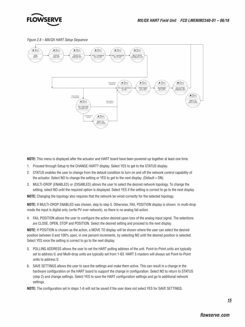
Figure 2.8 illustrates the setup sequence. For proper operation, the correct mode must be selected.
To set up the MX or QX HART device, enter the Setup mode as detailed in Installation and Operation Manual Bulletins LMENIM2306 for the MX and LMENIM3306 for the QX;
15
MX/QX HART Field Unit FCD LMENIM2340-01 – 06/16
flowserve.com
Figure 2.8 – MX/QX HART Setup Sequence
If Hart Actuator& Multidrop
If Hart Actuator& not Multidrop
If fail position isnot “position”
If fail position is“position”
VIEWHART?
POLLING ADDRESS(0)-OK?
PROP BAND(5%)-OK?
DEADBAND(2%)-OK?
ESD ACTION(IGNORE)-OK?
MOVE TOXXX% OPEN
FAIL POSITION(CLOSE)-OK?
MOVE TO XXX% OPEN
STATUS(ON)-OK?
DEVICE ID3295509-OK?
HART-1 FIRMWAREREV 25-OK?
HART-1 HARDWAREREV 25-OK?
MULTI-DROP(DISABLED)-OK?
NOTE: This menu is displayed after the actuator and HART board have been powered up together at least one time.
1. Proceed through Setup to the CHANGE HART? display. Select YES to get to the STATUS display.
2. STATUS enables the user to change from the default condition to turn on and off the network control capability of the actuator. Select NO to change the setting or YES to get to the next display. (Default = ON)
3. MULTI-DROP (ENABLED) or (DISABLED) allows the user to select the desired network topology. To change the setting, select NO until the required option is displayed. Select YES if the setting is correct to go to the next display.
NOTE: Changing the topology also requires that the network be wired correctly for the selected topology.
NOTE: If MULTI-DROP ENABLED was chosen, skip to step 5. Otherwise, FAIL POSITION display is shown. In multi-drop mode the input is digital only (write PV over network), so there is no analog fail action.
4. FAIL POSITION allows the user to configure the action desired upon loss of the analog input signal. The selections are CLOSE, OPEN, STOP and POSITION. Select the desired setting and proceed to the next display.
NOTE: If POSITION is chosen as the action, a MOVE TO display will be shown where the user can select the desired position between 0 and 100% open, in one percent increments, by selecting NO until the desired position is selected. Select YES once the setting is correct to go to the next display.
5. POLLING ADDRESS allows the user to set the HART polling address of the unit. Point-to-Point units are typically set to address 0, and Multi-drop units are typically set from 1-63. HART 5 masters will always set Point-to-Point units to address 0.
6. SAVE SETTINGS allows the user to save the settings and make them active. This can result in a change in the hardware configuration on the HART board to support the change in configuration. Select NO to return to STATUS (step 2) and change settings. Select YES to save the HART configuration settings and go to additional network settings.
NOTE: The configuration set in steps 1-6 will not be saved if the user does not select YES for SAVE SETTINGS.
MX/QX HART Field Unit FCD LMENIM2340-01 – 06/16
16
7. CHANGE PROP/DEADBAND allows for the setting of proportional band and deadband. Proportional band is the range of errors between the position and demand signal that will produce reduced speed (pulsing). The default value is 5%. To change from default, select NO until the required value is displayed. The value is adjustable between 1% and 100%, in 1% increments. The default deadband value is 2%. For error signals less than this, no motion occurs. The deadband should be wide enough to prevent “hunting” of the actuator but as low as possible to give adequate response to changes in the error signal. To change from the default, select NO to adjust the value between 1% and 50%, in 1% increments to suit the application.
8. ESD ACTION allows a network ESD function to be enabled after the ESD configuration has been established for the unit. This network ESD can be selected to do one of the following: ignore the command (NONE), CLOSE, OPEN, STOP or POSITION the actuator. To change from the default setting, select NO until the required option is displayed. Select YES if the setting is correct to go to the next display.
NOTE: If POSITION is chosen as the action, a MOVE TO display will be shown where the user can select the desired position between 0 and 100% open, in one percent increments, by selecting NO until the desired position is selected. Select YES once the setting is correct to go to the next display.
.2.6 Installation Verification
2.6.1 Network Cabling Installation Verification
After installation is complete and prior to operation, inspect the network cable and its connection to each field device.
NOTE: Units should be disconnected from power. The network should be disconnected from the host device.
Check for the following:
1. There should not be:
• Nicks in the insulation - this can cause a short to the grounded shield.• Cut strands in a stranded conductor - this can cause a poor connection and eventually an open circuit.
2. The shield/drain wire should only be grounded at one point in the segment to avoid ground loop problems.
3. The ground/earth connection should be at true ground potential and effective at all times. See step No. 5 in Section 2.4.1, Site Preparation.
2.6.2 MX/QX HART Device Installation Verification
Verify the field device is installed as follows:
1. Enter the Setup mode as detailed in Installation and Operation Manual Bulletins LMENIM2306 for the MX or LMENIM3306 for the QX.
2. In the Setup mode, use the black control knob to select YES to the main menu selection. VIEW DIAGNOSTICS?
3. Select YES to the display VIEW HARDWARE STATUS?
4. Select YES to scroll through the menu selections. The LCD will read HART BOARD 1 (OK) - NEXT? if installed.
NOTE: If the HART BOARD 1 (OK)? does not appear, contact Limitorque for assistance.
5. To return to the normal display, use the black knob to select either LOCAL or REMOTE.
17
MX/QX HART Field Unit FCD LMENIM2340-01 – 06/16
flowserve.com
2.7 Configuration ConfirmationField device operation cannot be verified until the complete HART system is operational. However, routine checks can be performed to verify many functions.
2.7.1 Checking Connections
Verify that all connections, including data wires, shield ground, digital inputs (optional), digital outputs (optional), and analog inputs are in accordance with MX/QX wiring diagrams and MX/QX HART device diagrams in Appendix A.
2.7.2 View Settings
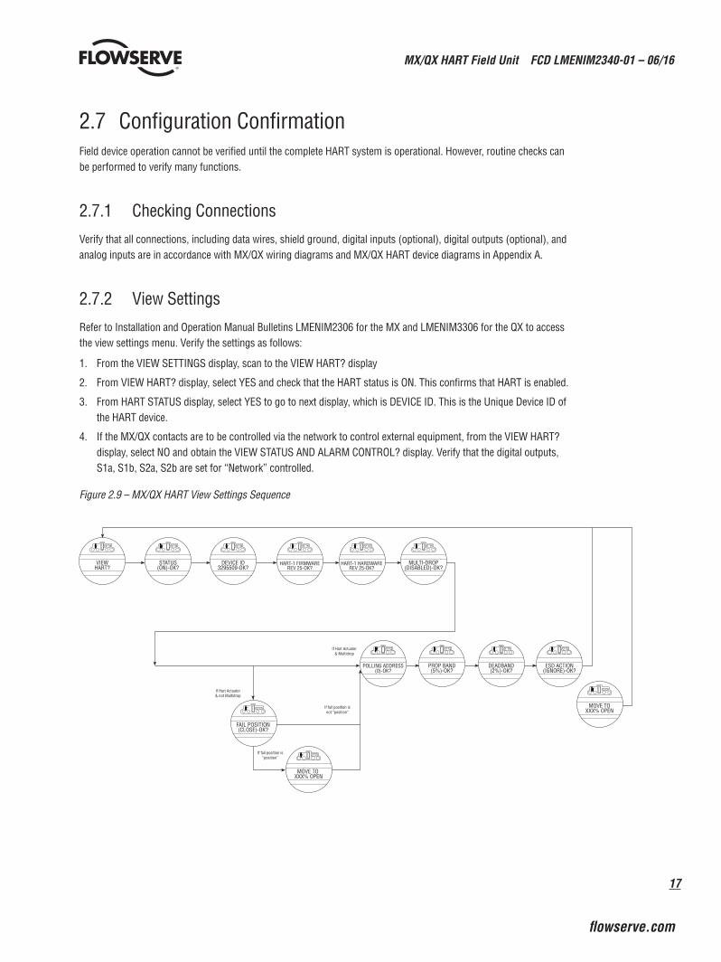
Refer to Installation and Operation Manual Bulletins LMENIM2306 for the MX and LMENIM3306 for the QX to access the view settings menu. Verify the settings as follows:
1. From the VIEW SETTINGS display, scan to the VIEW HART? display
2. From VIEW HART? display, select YES and check that the HART status is ON. This confirms that HART is enabled.
3. From HART STATUS display, select YES to go to next display, which is DEVICE ID. This is the Unique Device ID of the HART device.
4. If the MX/QX contacts are to be controlled via the network to control external equipment, from the VIEW HART? display, select NO and obtain the VIEW STATUS AND ALARM CONTROL? display. Verify that the digital outputs, S1a, S1b, S2a, S2b are set for “Network” controlled.
Figure 2.9 – MX/QX HART View Settings Sequence
If Hart Actuator& Multidrop
If Hart Actuator& not Multidrop
If fail position isnot “position”
If fail position is“position”
VIEWHART?
POLLING ADDRESS(0)-OK?
PROP BAND(5%)-OK?
DEADBAND(2%)-OK?
ESD ACTION(IGNORE)-OK?
MOVE TOXXX% OPEN
FAIL POSITION(CLOSE)-OK?
MOVE TO XXX% OPEN
STATUS(ON)-OK?
DEVICE ID3295509-OK?
HART-1 FIRMWAREREV 25-OK?
HART-1 HARDWAREREV 25-OK?
MULTI-DROP(DISABLED)-OK?
MX/QX HART Field Unit FCD LMENIM2340-01 – 06/16
18
2.7.3 Checking the Normal Display
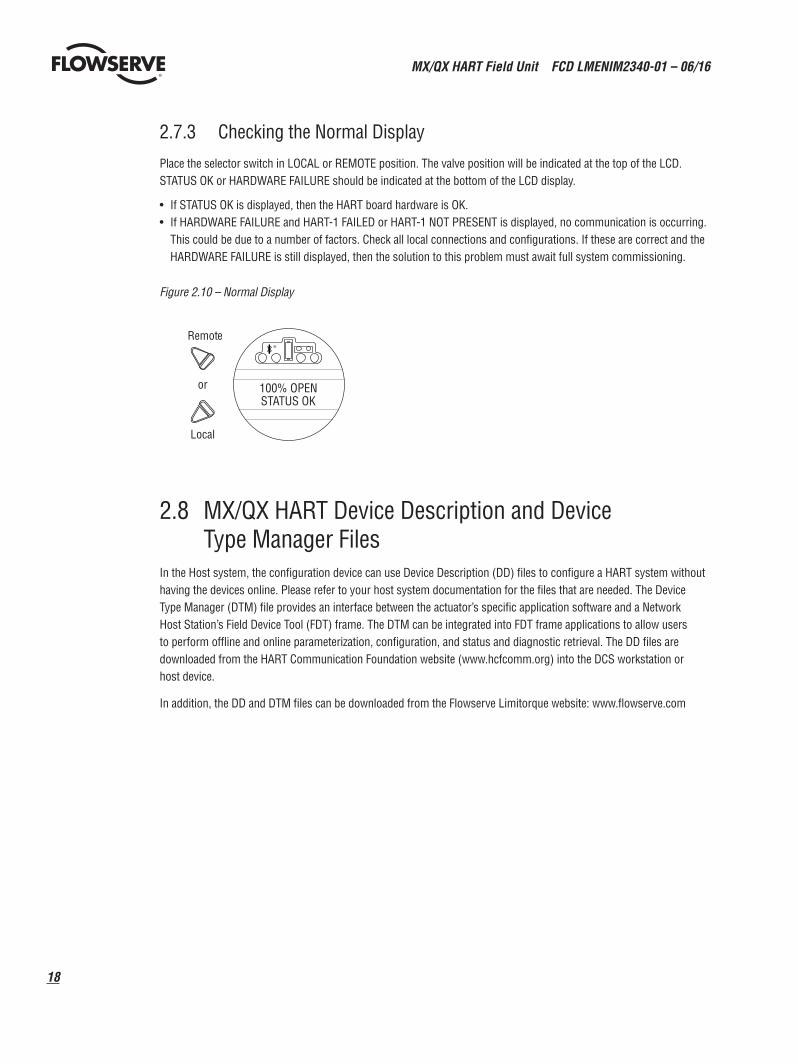
Place the selector switch in LOCAL or REMOTE position. The valve position will be indicated at the top of the LCD. STATUS OK or HARDWARE FAILURE should be indicated at the bottom of the LCD display.
• If STATUS OK is displayed, then the HART board hardware is OK.• If HARDWARE FAILURE and HART-1 FAILED or HART-1 NOT PRESENT is displayed, no communication is occurring.
This could be due to a number of factors. Check all local connections and configurations. If these are correct and the HARDWARE FAILURE is still displayed, then the solution to this problem must await full system commissioning.
Figure 2.10 – Normal Display
100% OPEN STATUS OK
Remot e
Local
or
2.8 MX/QX HART Device Description and Device Type Manager Files
In the Host system, the configuration device can use Device Description (DD) files to configure a HART system without having the devices online. Please refer to your host system documentation for the files that are needed. The Device Type Manager (DTM) file provides an interface between the actuator’s specific application software and a Network Host Station’s Field Device Tool (FDT) frame. The DTM can be integrated into FDT frame applications to allow users to perform offline and online parameterization, configuration, and status and diagnostic retrieval. The DD files are downloaded from the HART Communication Foundation website (www.hcfcomm.org) into the DCS workstation or host device.
In addition, the DD and DTM files can be downloaded from the Flowserve Limitorque website: www.flowserve.com
19
MX/QX HART Field Unit FCD LMENIM2340-01 – 06/16
flowserve.com
3 Software
3.1 HART ProtocolThe system uses the HART protocol to communicate over the HART network with other HART devices. The HART protocol is a master/slave communication service for process control devices. HART digital signaling is an extension of conventional analog signaling allowing the network signal to ride on the 4-20 mADC analog process signal. It uses 1200 bps binary phase-continuous Frequency-Shift-Keying (FSK), where a high frequency current is superimposed on a low-frequency (typically 4-20 mADC) analog current.
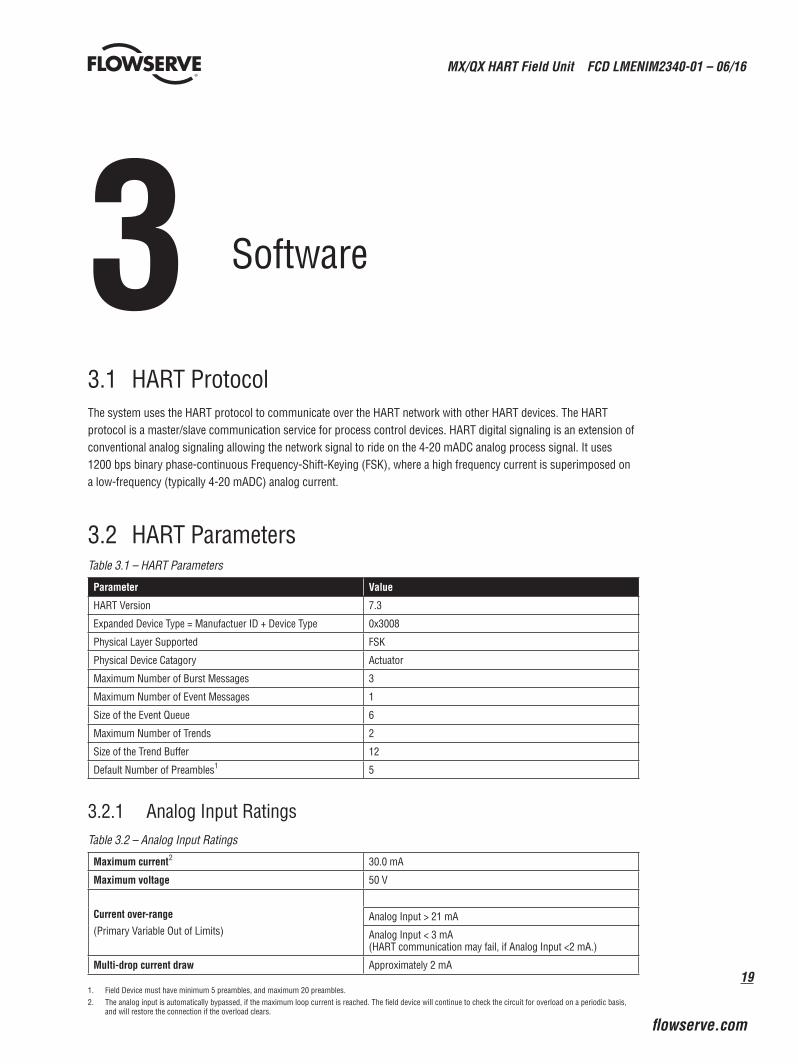
3.2 HART ParametersTable 3.1 – HART Parameters
Parameter Value
HART Version 7.3
Expanded Device Type = Manufactuer ID + Device Type 0x3008
Physical Layer Supported FSK
Physical Device Catagory Actuator
Maximum Number of Burst Messages 3
Maximum Number of Event Messages 1
Size of the Event Queue 6
Maximum Number of Trends 2
Size of the Trend Buffer 12
Default Number of Preambles1 5
3.2.1 Analog Input RatingsTable 3.2 – Analog Input Ratings
Maximum current2 30.0 mA
Maximum voltage 50 V
Current over-range
(Primary Variable Out of Limits)Analog Input > 21 mA
Analog Input < 3 mA (HART communication may fail, if Analog Input <2 mA.)
Multi-drop current draw Approximately 2 mA
1. Field Device must have minimum 5 preambles, and maximum 20 preambles.2. The analog input is automatically bypassed, if the maximum loop current is reached. The field device will continue to check the circuit for overload on a periodic basis,
and will restore the connection if the overload clears.
MX/QX HART Field Unit FCD LMENIM2340-01 – 06/16
20
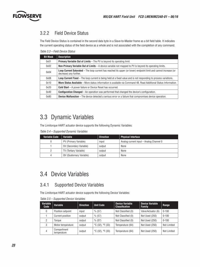
3.2.2 Field Device Status
The Field Device Status is contained in the second data byte in a Slave-to-Master frame as a bit field table. It indicates the current operating status of the field device as a whole and is not associated with the completion of any command.
Table 3.3 – Field Device Status
Bit Mask Description
0x01 Primary Variable Out of Limits – The PV is beyond its operating limit.
0x02 Non-Primary Variable Out of Limits – A device variable not mapped to PV is beyond its operating limits.
0x04 Loop Current Saturated – The loop current has reached its upper (or lower) endpoint limit and cannot increase (or decrease) any further.
0x08 Loop Current Fixed – The loop current is being held at a fixed value and is not responding to process variations.
0x10 More Status Available – More status information is available via Command 48, Read Additional Status Information.
0x20 Cold Start – A power failure or Device Reset has occurred.
0x40 Configuration Changed – An operation was performed that changed the device’s configuration.
0x80 Device Malfunction – The device detected a serious error or a failure that compromises device operation.
3.3 Dynamic VariablesThe Limitorque HART actuator device supports the following Dynamic Variables:
Table 3.4 – Supported Dynamic Variables
Variable Code Variable Direction Physical Interface
0 PV (Primary Variable) input Analog current input – Analog Channel 0
1 SV (Secondary Variable) output None
2 TV (Tertiary Variable) output None
4 QV (Quaternary Variable) output None
3.4 Device Variables
3.4.1 Supported Device Variables
The Limitorque HART actuator device supports the following Device Variables:
Table 3.5 – Supported Device Variables Variable
Code Variable Direction Unit Code Device Variable Classification
Device Variable Family Range
0 Position setpoint input % (57) Not Classified (0) Valve/Actuator (6) 0-100
1 Current position output % (57) Not Classified (0) Not Used (250) 0-100
2 Torque output % (57) Not Classified (0) Not Used (250) 0-100
3 Motor temperature output °C (32), °F (33) Temperature (64) Not Used (250) Not Limited
4 Compartment temperature output °C (32), °F (33) Temperature (64) Not Used (250) Not Limited
21
MX/QX HART Field Unit FCD LMENIM2340-01 – 06/16
flowserve.com
3.4.2 Device Variable Mapping
Device Variables may be mapped to the Dynamic Variables according to the following table:
Table 3.6 – Mapping of Device Variables to Dynamic Variables
Variable Code
Dynamic Variable Direction Default Device Variable Device Variables which may be mapped to the
Dynamic Variable
0 PV input Position Setpoint Position Setpoint
1 SV output Current Position Current Position or Torque
2 TV output Motor Temperature Current Position, Torque, Motor Temperature or Compartment temperature
3 QV output Compartment Temperature Current Position, Torque, Motor Temperature or Compartment temperature
No single Device Variable may be mapped to more than one Dynamic Variable.
For Example:
Valid Mapping: Invalid Mapping:PV = DV0 PV = DV0SV = DV1 SV = DV1TV = DV3 TV = DV1QV = DV4 QV = DV4
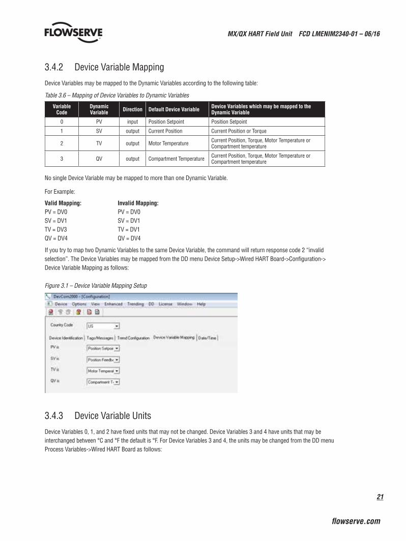
If you try to map two Dynamic Variables to the same Device Variable, the command will return response code 2 “invalid selection”. The Device Variables may be mapped from the DD menu Device Setup->Wired HART Board->Configuration-> Device Variable Mapping as follows:
Figure 3.1 – Device Variable Mapping Setup
3.4.3 Device Variable Units
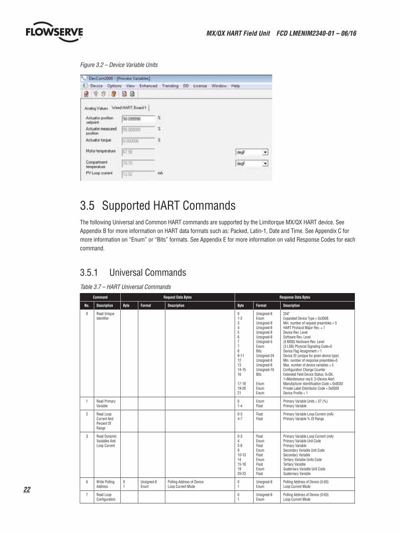
Device Variables 0, 1, and 2 have fixed units that may not be changed. Device Variables 3 and 4 have units that may be interchanged between °C and °F the default is °F. For Device Variables 3 and 4, the units may be changed from the DD menu Process Variables->Wired HART Board as follows:
MX/QX HART Field Unit FCD LMENIM2340-01 – 06/16
22
Figure 3.2 – Device Variable Units
3.5 Supported HART CommandsThe following Universal and Common HART commands are supported by the Limitorque MX/QX HART device. See Appendix B for more information on HART data formats such as: Packed, Latin-1, Date and Time. See Appendix C for more information on “Enum” or “Bits” formats. See Appendix E for more information on valid Response Codes for each command.
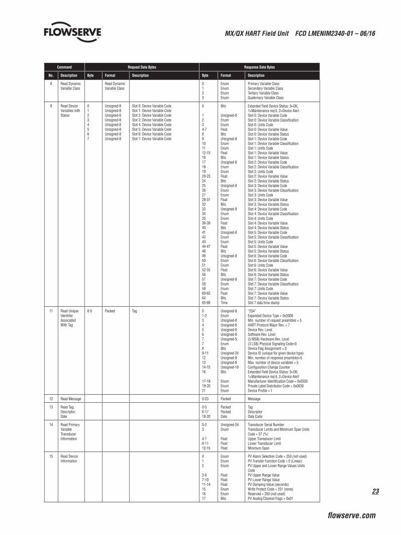
3.5.1 Universal CommandsTable 3.7 – HART Universal Commands
Command Request Data Bytes Response Data Bytes
No. Description Byte Format Description Byte Format Description
0 Read Unique Identifier
01-234567789-11121314-1516
17-1819-2021
Unsigned-8EnumUnsigned-8Unsigned-8Unsigned-8Unsigned-8Unsigned-5EnumBitsUnsigned-24Unsigned-8Unsigned-8Unsigned-16Bits
EnumEnumEnum
254”Expanded Device Type = 0x3008Min. number of request preambles = 5HART Protocol Major Rev. = 7Device Rev. Level Software Rev. Level (5 MSB) Hardware Rev. Level (3 LSB) Physical Signaling Code=0Device Flag Assignment = 1Device ID (unique for given device type)Min. number of response preambles=5Max. number of device variables = 5Configuration Change CounterExtended Field Device Status: 0=OK, 1=Maintenance req’d, 2=Device AlertManufacturer Identification Code = 0x0030Private Label Distributor Code = 0x0030Device Profile = 1
1 Read Primary Variable
01-4
EnumFloat
Primary Variable Units = 57 (%) Primary Variable
2 Read Loop Current And Percent Of Range
0-34-7
FloatFloat
Primary Variable Loop Current (mA)Primary Variable % Of Range
3 Read Dynamic Variables And Loop Current
0-345-8910-131415-181920-23
FloatEnumFloatEnumFloatEnumFloatEnumFloat
Primary Variable Loop Current (mA)Primary Variable Unit Code Primary Variable Secondary Variable Unit Code Secondary VariableTertiary Variable Units Code Tertiary VariableQuaternary Variable Unit Code Quaternary Variable
6 Write Polling Address
01
Unsigned-8Enum
Polling Address of DeviceLoop Current Mode
01
Unsigned-8Enum
Polling Address of Device (0-63)Loop Current Mode
7 Read Loop Configuration
01
Unsigned-8Enum
Polling Address of Device (0-63)Loop Current Mode
23
MX/QX HART Field Unit FCD LMENIM2340-01 – 06/16
flowserve.com
Command Request Data Bytes Response Data Bytes
No. Description Byte Format Description Byte Format Description
8 Read Dynamic Variable Class
Read Dynamic Variable Class
0123
EnumEnumEnumEnum
Primary Variable Class Secondary Variable Class Tertiary Variable Class Quaternary Variable Class
9 Read Device Variables with Status
01234567
Unsigned-8Unsigned-8Unsigned-8Unsigned-8Unsigned-8Unsigned-8Unsigned-8Unsigned-8
Slot 0: Device Variable CodeSlot 1: Device Variable CodeSlot 2: Device Variable CodeSlot 3: Device Variable CodeSlot 4: Device Variable CodeSlot 5: Device Variable CodeSlot 6: Device Variable CodeSlot 7: Device Variable Code
0
1234-789101112-151617181920-232425262728-313233343536-394041424344-474849505152-555657585960-636465-68
Bits
Unsigned-8EnumEnumFloatBitsUnsigned-8EnumEnumFloatBitsUnsigned-8EnumEnumFloatBitsUnsigned-8EnumEnumFloatBitsUnsigned-8EnumEnumFloatBitsUnsigned-8EnumEnumFloatBitsUnsigned-8EnumEnumFloatBitsUnsigned-8EnumEnumFloatBitsTime
Extended Field Device Status: 0=OK, 1=Maintenance req’d, 2=Device AlertSlot 0: Device Variable CodeSlot 0: Device Variable ClassificationSlot 0: Units CodeSlot 0: Device Variable ValueSlot 0: Device Variable StatusSlot 1: Device Variable CodeSlot 1: Device Variable ClassificationSlot 1: Units CodeSlot 1: Device Variable ValueSlot 1: Device Variable StatusSlot 2: Device Variable CodeSlot 2: Device Variable ClassificationSlot 2: Units CodeSlot 2: Device Variable ValueSlot 2: Device Variable StatusSlot 3: Device Variable CodeSlot 3: Device Variable ClassificationSlot 3: Units CodeSlot 3: Device Variable ValueSlot 3: Device Variable StatusSlot 4: Device Variable CodeSlot 4: Device Variable ClassificationSlot 4: Units CodeSlot 4: Device Variable ValueSlot 4: Device Variable StatusSlot 5: Device Variable CodeSlot 5: Device Variable ClassificationSlot 5: Units CodeSlot 5: Device Variable ValueSlot 5: Device Variable StatusSlot 6: Device Variable CodeSlot 6: Device Variable ClassificationSlot 6: Units CodeSlot 6: Device Variable ValueSlot 6: Device Variable StatusSlot 7: Device Variable CodeSlot 7: Device Variable ClassificationSlot 7: Units CodeSlot 7: Device Variable ValueSlot 7: Device Variable StatusSlot 7 data time stamp
11 Read Unique Identifier Associated With Tag
0-5 Packed Tag 01-234567789-11121314-1516
17-1819-2021
Unsigned-8EnumUnsigned-8Unsigned-8Unsigned-8Unsigned-8Unsigned-5EnumBitsUnsigned-24Unsigned-8Unsigned-8Unsigned-16Bits
EnumEnumEnum
“254”Expanded Device Type = 0x3008Min. number of request preambles = 5HART Protocol Major Rev. = 7Device Rev. Level Software Rev. Level (5 MSB) Hardware Rev. Level (3 LSB) Physical Signaling Code=0Device Flag Assignment = 0Device ID (unique for given device type)Min. number of response preambles=5Max. number of device variables = 5Configuration Change CounterExtended Field Device Status: 0=OK, 1=Maintenance req’d, 2=Device AlertManufacturer Identification Code = 0x0030Private Label Distributor Code = 0x0030Device Profile = 1
12 Read Message 0-23 Packed Message
13 Read Tag, Descriptor, Date
0-56-1718-20
PackedPackedDate
TagDescriptorDate Code
14 Read Primary Variable Transducer Information
0-23
4-78-1112-15
Unsigned-24Enum
FloatFloatFloat
Transducer Serial NumberTransducer Limits and Minimum Span Units Code = 57 (%)Upper Transducer LimitLower Transducer LimitMinimum Span
15 Read Device Information
012
3-67-1011-14151617
EnumEnumEnum
FloatFloatFloat EnumEnumBits
PV Alarm Selection Code = 250 (not used)PV Transfer Function Code = 0 (Linear)PV Upper and Lower Range Values Units CodePV Upper Range ValuePV Lower Range ValuePV Damping Value (seconds)Write Protect Code = 251 (none)Reserved = 250 (not used)PV Analog Channel Flags = 0x01
MX/QX HART Field Unit FCD LMENIM2340-01 – 06/16
24
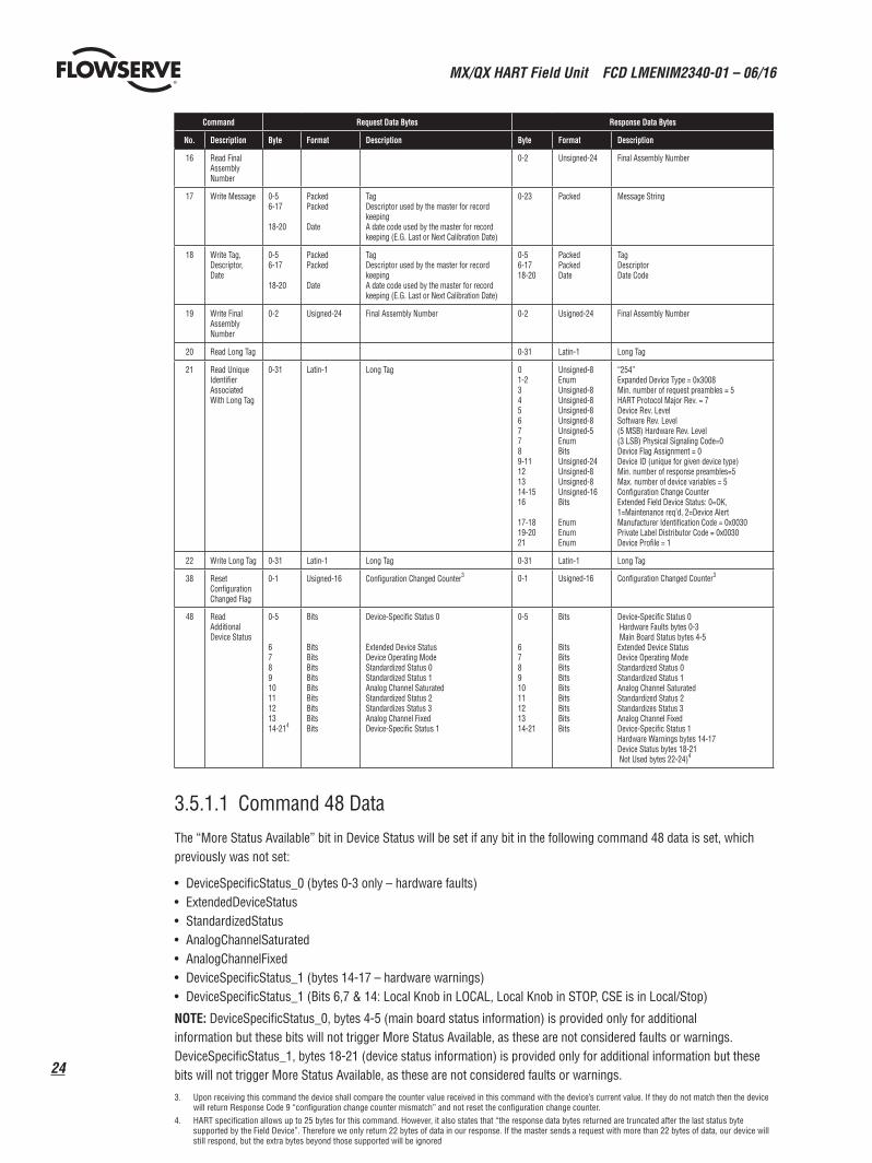
Command Request Data Bytes Response Data Bytes
No. Description Byte Format Description Byte Format Description
16 Read Final Assembly Number
0-2 Unsigned-24 Final Assembly Number
17 Write Message 0-56-17
18-20
PackedPacked
Date
TagDescriptor used by the master for record keepingA date code used by the master for record keeping (E.G. Last or Next Calibration Date)
0-23 Packed Message String
18 Write Tag, Descriptor, Date
0-56-17
18-20
PackedPacked
Date
TagDescriptor used by the master for record keepingA date code used by the master for record keeping (E.G. Last or Next Calibration Date)
0-56-1718-20
PackedPackedDate
TagDescriptor Date Code
19 Write Final Assembly Number
0-2 Usigned-24 Final Assembly Number 0-2 Usigned-24 Final Assembly Number
20 Read Long Tag 0-31 Latin-1 Long Tag
21 Read Unique Identifier Associated With Long Tag
0-31 Latin-1 Long Tag 01-234567789-11121314-1516
17-1819-2021
Unsigned-8EnumUnsigned-8Unsigned-8Unsigned-8Unsigned-8Unsigned-5EnumBitsUnsigned-24Unsigned-8Unsigned-8Unsigned-16Bits
EnumEnumEnum
“254”Expanded Device Type = 0x3008Min. number of request preambles = 5HART Protocol Major Rev. = 7Device Rev. Level Software Rev. Level (5 MSB) Hardware Rev. Level (3 LSB) Physical Signaling Code=0Device Flag Assignment = 0Device ID (unique for given device type)Min. number of response preambles=5Max. number of device variables = 5Configuration Change CounterExtended Field Device Status: 0=OK, 1=Maintenance req’d, 2=Device AlertManufacturer Identification Code = 0x0030Private Label Distributor Code = 0x0030Device Profile = 1
22 Write Long Tag 0-31 Latin-1 Long Tag 0-31 Latin-1 Long Tag
38 Reset Configuration Changed Flag
0-1 Usigned-16 Configuration Changed Counter3 0-1 Usigned-16 Configuration Changed Counter3
48 Read Additional Device Status
0-5
67891011121314-214
Bits
BitsBitsBitsBitsBitsBitsBitsBitsBits
Device-Specific Status 0
Extended Device StatusDevice Operating ModeStandardized Status 0Standardized Status 1Analog Channel SaturatedStandardized Status 2Standardizes Status 3Analog Channel FixedDevice-Specific Status 1
0-5
67891011121314-21
Bits
BitsBitsBitsBitsBitsBitsBitsBitsBits
Device-Specific Status 0 Hardware Faults bytes 0-3 Main Board Status bytes 4-5 Extended Device StatusDevice Operating ModeStandardized Status 0Standardized Status 1Analog Channel SaturatedStandardized Status 2Standardizes Status 3Analog Channel FixedDevice-Specific Status 1Hardware Warnings bytes 14-17Device Status bytes 18-21 Not Used bytes 22-24)4
3.5.1.1 Command 48 Data
The “More Status Available” bit in Device Status will be set if any bit in the following command 48 data is set, which previously was not set:
• DeviceSpecificStatus_0 (bytes 0-3 only – hardware faults)• ExtendedDeviceStatus• StandardizedStatus• AnalogChannelSaturated• AnalogChannelFixed• DeviceSpecificStatus_1 (bytes 14-17 – hardware warnings)• DeviceSpecificStatus_1 (Bits 6,7 & 14: Local Knob in LOCAL, Local Knob in STOP, CSE is in Local/Stop)
NOTE: DeviceSpecificStatus_0, bytes 4-5 (main board status information) is provided only for additional information but these bits will not trigger More Status Available, as these are not considered faults or warnings. DeviceSpecificStatus_1, bytes 18-21 (device status information) is provided only for additional information but these bits will not trigger More Status Available, as these are not considered faults or warnings.
3. Upon receiving this command the device shall compare the counter value received in this command with the device’s current value. If they do not match then the device will return Response Code 9 “configuration change counter mismatch” and not reset the configuration change counter.
4. HART specification allows up to 25 bytes for this command. However, it also states that “the response data bytes returned are truncated after the last status byte supported by the Field Device”. Therefore we only return 22 bytes of data in our response. If the master sends a request with more than 22 bytes of data, our device will still respond, but the extra bytes beyond those supported will be ignored
25
MX/QX HART Field Unit FCD LMENIM2340-01 – 06/16
flowserve.com
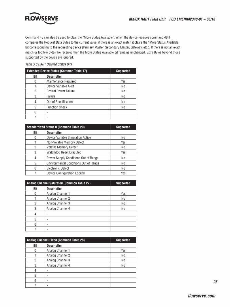
Command 48 can also be used to clear the “More Status Available”. When the device receives command 48 it compares the Request Data Bytes to the current value; if there is an exact match it clears the “More Status Available bit corresponding to the requesting device (Primary Master, Secondary Master, Gateway, etc.). If there is not an exact match or too few bytes are received then the More Status Available bit remains unchanged. Extra Bytes beyond those supported by the device are ignored.
Table 3.8 HART Defined Status Bits
Extended Device Status (Common Table 17) Supported
Bit Description0 Maintenance Required Yes1 Device Variable Alert No2 Critical Power Failure No3 Failure No
4 Out of Specification No
5 Function Check No6 -7 -
Standardized Status 0 (Common Table 29) Supported
Bit Description0 Device Variable Simulation Active No1 Non-Volatile Memory Defect Yes2 Volatile Memory Defect No3 Watchdog Reset Executed Yes
4 Power Supply Conditions Out of Range No
5 Environmental Conditions Out of Range No6 Electronic Defect No7 Device Configuration Locked Yes
Analog Channel Saturated (Common Table 27) Supported
Bit Description0 Analog Channel 1 Yes1 Analog Channel 2 No2 Analog Channel 3 No3 Analog Channel 4 No
4 -
5 -6 -7 -
Analog Channel Fixed (Common Table 28) Supported
Bit Description0 Analog Channel 1 Yes1 Analog Channel 2 No2 Analog Channel 3 No3 Analog Channel 4 No4 -5 -6 -7 -
MX/QX HART Field Unit FCD LMENIM2340-01 – 06/16
26
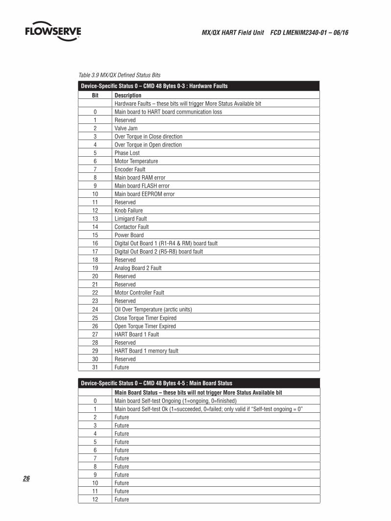
Table 3.9 MX/QX Defined Status Bits
Device-Specific Status 0 – CMD 48 Bytes 0-3 : Hardware Faults
Bit DescriptionHardware Faults – these bits will trigger More Status Available bit
0 Main board to HART board communication loss1 Reserved2 Valve Jam3 Over Torque in Close direction4 Over Torque in Open direction5 Phase Lost6 Motor Temperature7 Encoder Fault8 Main board RAM error9 Main board FLASH error10 Main board EEPROM error11 Reserved12 Knob Failure13 Limigard Fault14 Contactor Fault15 Power Board16 Digital Out Board 1 (R1-R4 & RM) board fault17 Digital Out Board 2 (R5-R8) board fault18 Reserved19 Analog Board 2 Fault20 Reserved21 Reserved22 Motor Controller Fault23 Reserved24 Oil Over Temperature (arctic units)25 Close Torque Timer Expired26 Open Torque Timer Expired27 HART Board 1 Fault28 Reserved29 HART Board 1 memory fault30 Reserved31 Future
Device-Specific Status 0 – CMD 48 Bytes 4-5 : Main Board Status
Main Board Status – these bits will not trigger More Status Available bit0 Main board Self-test Ongoing (1=ongoing, 0=finished)1 Main board Self-test Ok (1=succeeded, 0=failed; only valid if “Self-test ongoing = 0”2 Future3 Future4 Future5 Future6 Future7 Future8 Future9 Future10 Future11 Future12 Future
27
MX/QX HART Field Unit FCD LMENIM2340-01 – 06/16
flowserve.com
13 Future14 Future15 Future
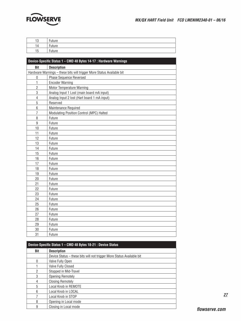
Device-Specific Status 1 – CMD 48 Bytes 14-17 : Hardware Warnings
Bit DescriptionHardware Warnings – these bits will trigger More Status Available bit
0 Phase Sequence Reversed1 Encoder Warning2 Motor Temperature Warning3 Analog Input 1 Lost (main board mA input)4 Analog Input 2 lost (Hart board 1 mA input)5 Reserved6 Maintenance Required7 Modulating Position Control (MPC) Halted8 Future9 Future10 Future11 Future12 Future13 Future14 Future15 Future16 Future17 Future18 Future19 Future20 Future21 Future22 Future23 Future24 Future25 Future26 Future27 Future28 Future29 Future30 Future31 Future
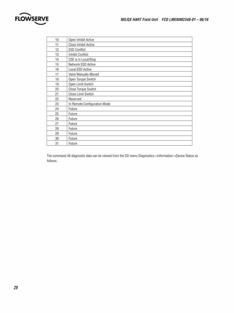
Device-Specific Status 1 – CMD 48 Bytes 18-21 : Device Status
Bit DescriptionDevice Status – these bits will not trigger More Status Available bit
0 Valve Fully Open1 Valve Fully Closed2 Stopped in Mid-Travel3 Opening Remotely4 Closing Remotely5 Local Knob in REMOTE6 Local Knob in LOCAL7 Local Knob in STOP8 Opening in Local mode9 Closing in Local mode
MX/QX HART Field Unit FCD LMENIM2340-01 – 06/16
28
10 Open Inhibit Active11 Close Inhibit Active12 ESD Conflict13 Inhibit Conflict14 CSE is in Local/Stop15 Network ESD Active16 Local ESD Active17 Valve Manually Moved18 Open Torque Switch 19 Open Limit Switch20 Close Torque Switch21 Close Limit Switch22 Reserved23 In Remote Configuration Mode 24 Future25 Future26 Future27 Future28 Future29 Future30 Future31 Future
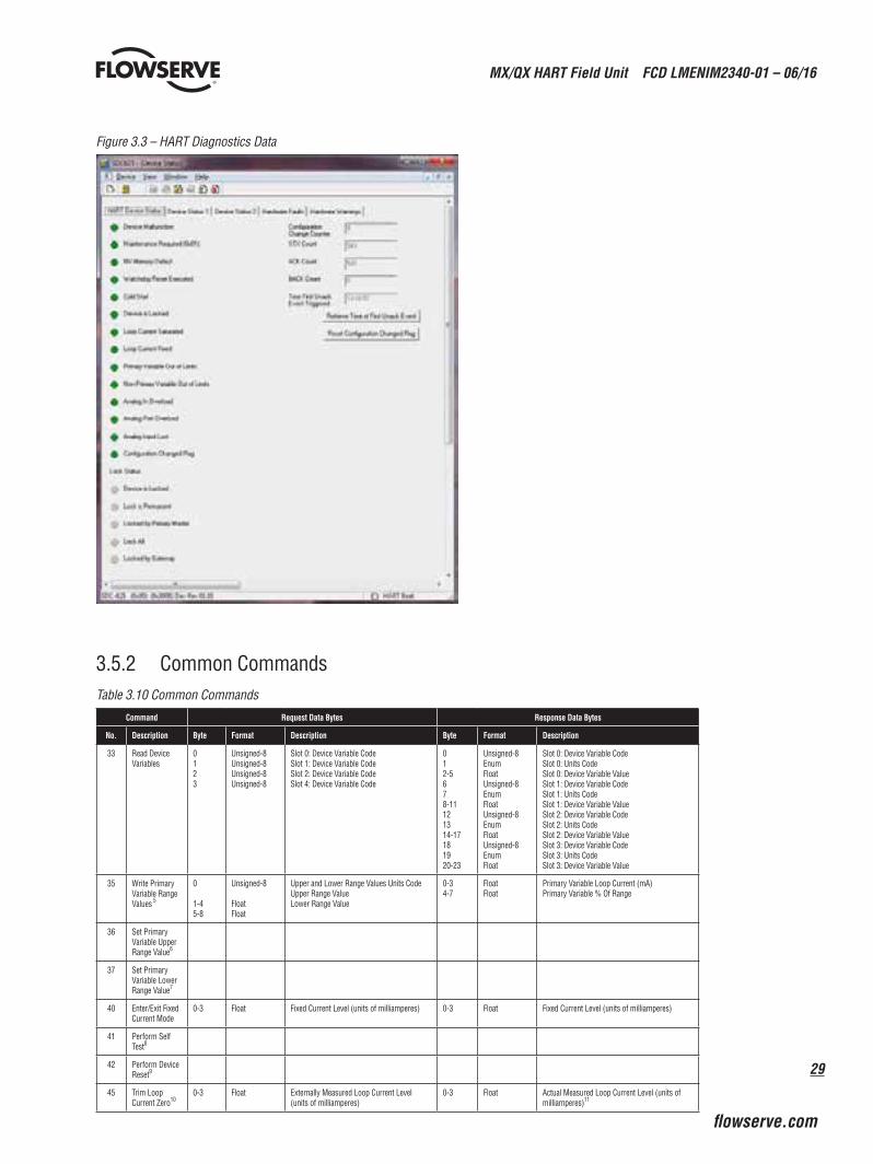
The command 48 diagnostic data can be viewed from the DD menu Diagnostics->Information->Device Status as follows:
29
MX/QX HART Field Unit FCD LMENIM2340-01 – 06/16
flowserve.com
Figure 3.3 – HART Diagnostics Data
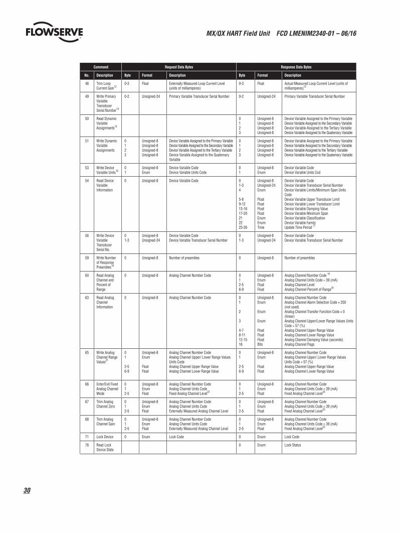
3.5.2 Common CommandsTable 3.10 Common Commands
Command Request Data Bytes Response Data Bytes
No. Description Byte Format Description Byte Format Description
33 Read Device Variables
0123
Unsigned-8Unsigned-8Unsigned-8Unsigned-8
Slot 0: Device Variable CodeSlot 1: Device Variable CodeSlot 2: Device Variable CodeSlot 4: Device Variable Code
012-5678-11121314-17181920-23
Unsigned-8EnumFloatUnsigned-8EnumFloatUnsigned-8EnumFloatUnsigned-8EnumFloat
Slot 0: Device Variable CodeSlot 0: Units CodeSlot 0: Device Variable ValueSlot 1: Device Variable CodeSlot 1: Units CodeSlot 1: Device Variable ValueSlot 2: Device Variable CodeSlot 2: Units CodeSlot 2: Device Variable ValueSlot 3: Device Variable CodeSlot 3: Units CodeSlot 3: Device Variable Value
35 Write Primary Variable Range Values 5
0
1-45-8
Unsigned-8
FloatFloat
Upper and Lower Range Values Units CodeUpper Range ValueLower Range Value
0-34-7
FloatFloat
Primary Variable Loop Current (mA)Primary Variable % Of Range
36 Set Primary Variable Upper Range Value6
37 Set Primary Variable Lower Range Value7
40 Enter/Exit Fixed Current Mode
0-3 Float Fixed Current Level (units of milliamperes) 0-3 Float Fixed Current Level (units of milliamperes)
41 Perform Self Test8
42 Perform Device Reset9
45 Trim Loop Current Zero10
0-3 Float Externally Measured Loop Current Level (units of milliamperes)
0-3 Float Actual Measured Loop Current Level (units of milliamperes)11
MX/QX HART Field Unit FCD LMENIM2340-01 – 06/16
30
Command Request Data Bytes Response Data Bytes
No. Description Byte Format Description Byte Format Description
46 Trim Loop Current Gain12
0-3 Float Externally Measured Loop Current Level (units of milliamperes)
0-3 Float Actual Measured Loop Current Level (units of milliamperes)13
49 Write Primary Variable Transducer Serial Number14
0-2 Unsigned-24 Primary Variable Transducer Serial Number 0-2 Unsigned-24 Primary Variable Transducer Serial Number
50 Read Dynamic Variable Assignments15
0123
Unsigned-8Unsigned-8Unsigned-8Unsigned-8
Device Variable Assigned to the Primary VariableDevice Variable Assigned to the Secondary VariableDevice Variable Assigned to the Tertiary VariableDevice Variable Assigned to the Quaternary Variable
51 Write Dynamic Variable Assignments
0123
Unsigned-8Unsigned-8Unsigned-8Unsigned-8
Device Variable Assigned to the Primary VariableDevice Variable Assigned to the Secondary VariableDevice Variable Assigned to the Tertiary VariableDevice Variable Assigned to the Quaternary Variable
0123
Unsigned-8Unsigned-8Unsigned-8Unsigned-8
Device Variable Assigned to the Primary VariableDevice Variable Assigned to the Secondary VariableDevice Variable Assigned to the Tertiary VariableDevice Variable Assigned to the Quaternary Variable
53 Write Device Variable Units16
01
Unsigned-8Enum
Device Variable CodeDevice Variable Units Code
01
Unsigned-8Enum
Device Variable CodeDevice Variable Units Cod
54 Read Device Variable Information
0 Unsigned-8 Device Variable Code 01-34
5-89-1213-1617-20212223-26
Unsigned-8Unsigned-24Enum
FloatFloatFloatFloatEnumEnumTime
Device Variable CodeDevice Variable Transducer Serial NumberDevice Variable Limits/Minimum Span Units CodeDevice Variable Upper Transducer LimitDevice Variable Lower Transducer LimitDevice Variable Damping ValueDevice Variable Minimum SpanDevice Variable ClassificationDevice Variable FamilyUpdate Time Period 17
56 Write Device Variable Transducer Serial No.
01-3
Unsigned-8Unsigned-24
Device Variable CodeDevice Variable Transducer Serial Number
01-3
Unsigned-8Unsigned-24
Device Variable CodeDevice Variable Transducer Serial Number
59 Write Number of Response Preambles18
0 Unsigned-8 Number of preambles 0 Unsigned-8 Number of preambles
60 Read Analog Channel and Percent of Range
0 Unsigned-8 Analog Channel Number Code 012-56-9
Unsigned-8EnumFloatFloat
Analog Channel Number Code 19
Analog Channel Units Code = 39 (mA)Analog Channel LevelAnalog Channel Percent of Range20
63 Read Analog Channel Information
0 Unsigned-8 Analog Channel Number Code 01
2
3
4-78-1112-1516
Unsigned-8Enum
Enum
Enum
FloatFloatFloatBits
Analog Channel Number CodeAnalog Channel Alarm Selection Code = 250 (not used)Analog Channel Transfer Function Code = 0 (linear)Analog Channel Upper/Lower Range Values Units Code = 57 (%)Analog Channel Upper Range ValueAnalog Channel Lower Range ValueAnalog Channel Damping Value (seconds)Analog Channel Flags
65 Write Analog Channel Range Values21
01
2-56-9
Unsigned-8Enum
FloatFloat
Analog Channel Number CodeAnalog Channel Upper/ Lower Range Values Units CodeAnalog Channel Upper Range ValueAnalog Channel Lower Range Value
01
2-56-9
Unsigned-8Enum
FloatFloat
Analog Channel Number CodeAnalog Channel Upper/ Lower Range Values Units Code = 57 (%)Analog Channel Upper Range ValueAnalog Channel Lower Range Value
66 Enter/Exit Fixed Analog Channel Mode
012-5
Unsigned-8EnumFloat
Analog Channel Number CodeAnalog Channel Units CodeFixed Analog Channel Level22
012-5
Unsigned-8EnumFloat
Analog Channel Number CodeAnalog Channel Units Code = 39 (mA)Fixed Analog Channel Level23
67 Trim Analog Channel Zero
012-5
Unsigned-8EnumFloat
Analog Channel Number CodeAnalog Channel Units CodeExternally Measured Analog Channel Level
012-5
Unsigned-8EnumFloat
Analog Channel Number CodeAnalog Channel Units Code = 39 (mA)Fixed Analog Channel Level23
68 Trim Analog Channel Gain
012-5
Unsigned-8EnumFloat
Analog Channel Number CodeAnalog Channel Units CodeExternally Measured Analog Channel Level
012-5
Unsigned-8EnumFloat
Analog Channel Number CodeAnalog Channel Units Code = 39 (mA)Fixed Analog Channel Level23
71 Lock Device 0 Enum Lock Code 0 Enum Lock Code
76 Read Lock Device State
0 Enum Lock Status
31
MX/QX HART Field Unit FCD LMENIM2340-01 – 06/16
flowserve.com
Command Request Data Bytes Response Data Bytes
No. Description Byte Format Description Byte Format Description
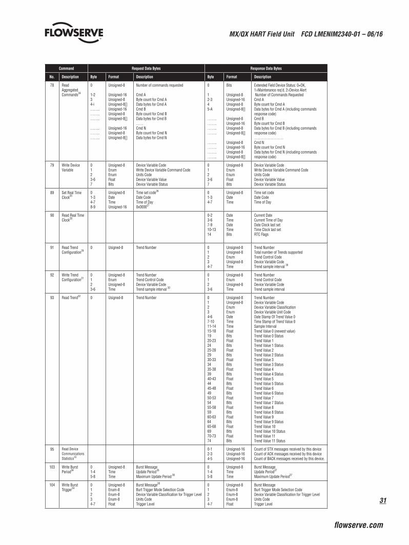
78 Read Aggregated Commands24
0
1-234-i……..……..……..
……..……..……..
Unsigned-8
Unsigned-16Unsigned-8Unsigned-8[]Unsigned-16Unsigned-8Unsigned-8[]
Unsigned-16Unsigned-8Unsigned-8[]
Number of commands requested
Cmd AByte count for Cmd AData bytes for Cmd ACmd BByte count for Cmd BData bytes for Cmd B……Cmd NByte count for Cmd NData bytes for Cmd N
0
12-345-A
……..……..……..……..
……..……..……..……..
Bits
Unsigned-8Unsigned-16Unsigned-8Unsigned-8[]
Unsigned-8Unsigned-16Unsigned-8Unsigned-8[]
Unsigned-8Unsigned-16Unsigned-8Unsigned-8[]
Extended Field Device Status: 0=OK, 1=Maintenance req’d, 2=Device Alert Number of Commands RequestedCmd AByte count for Cmd AData bytes for Cmd A (including commands response code)Cmd BByte count for Cmd BData bytes for Cmd B (including commands response code)……………………Cmd NByte count for Cmd NData bytes for Cmd N (including commands response code)
79 Write Device Variable
0123-67
Unsigned-8EnumEnumFloatBits
Device Variable CodeWrite Device Variable Command CodeUnits CodeDevice Variable ValueDevice Variable Status
0123-67
Unsigned-8EnumEnumFloatBits
Device Variable CodeWrite Device Variable Command CodeUnits CodeDevice Variable ValueDevice Variable Status
89 Set Real Time Clock25
01-34-78-9
Unsigned-8DateTimeUnsigned-16
Time set code26
Date CodeTime of Day0x000027
01-34-7
Unsigned-8DateTime
Time set codeDate CodeTime of Day
90 Read Real Time Clock28
0-23-67-910-1314
DateTimeDateTimeBits
Current DateCurrent Time of DayDate Clock last setTime Clock last setRTC Flags
91 Read Trend Configuration29
0 Usigned-8 Trend Number 01234-7
Unsigned-8Unsigned-8EnumUnsigned-8Time
Trend NumberTotal number of Trends supportedTrend Control CodeDevice Variable CodeTrend sample interval 30
92 Write Trend Configuration31
0123-6
Unsigned-8EnumUnsigned-8Time
Trend NumberTrend Control CodeDevice Variable CodeTrend sample interval 30
0123-6
Unsigned-8EnumUnsigned-8Time
Trend NumberTrend Control CodeDevice Variable CodeTrend sample interval
93 Read Trend32 0 Usigned-8 Trend Number 01234-67-1011-1415-181920-232425-282930-333435-383940-434445-484950-535455-585960-636465-686970-7374
Unsigned-8Unsigned-8EnumEnumDateTimeTimeFloatBitsFloatBitsFloatBitsFloatBitsFloatBits FloatBitsFloatBitsFloatBitsFloatBitsFloatBitsFloatBitsFloatBits
Trend NumberDevice Variable CodeDevice Variable ClassificationDevice Variable Unit CodeDate Stamp Of Trend Value 0Time Stamp of Trend Value 0Sample IntervalTrend Value 0 (newest value)Trend Value 0 StatusTrend Value 1Trend Value 1 StatusTrend Value 2Trend Value 2 StatusTrend Value 3Trend Value 3 StatusTrend Value 4Trend Value 4 StatusTrend Value 5Trend Value 5 StatusTrend Value 6Trend Value 6 StatusTrend Value 7Trend Value 7 StatusTrend Value 8Trend Value 8 StatusTrend Value 9Trend Value 9 StatusTrend Value 10Trend Value 10 StatusTrend Value 11Trend Value 11 Status
95 Read Device CommunicationsStatistics33
0-12-34-5
Unsigned-16Unsigned-16Unsigned-16
Count of STX messages received by this deviceCount of ACK messages received by this deviceCount of BACK messages received by this device.
103 Write Burst Period34
01-45-8
Unsigned-8TimeTime
Burst MessageUpdate Period 35
Maximum Update Period 36
01-45-8
Unsigned-8TimeTime
Burst MessageUpdate Period37 Maximum Update Period37
104 Write Burst Trigger34
01234-7
Unsigned-8Enum-8Enum-8Enum-8Float
Burst Message38
Burt Trigger Mode Selection CodeDevice Variable Classification for Trigger LevelUnits CodeTrigger Level
01234-7
Unsigned-8Enum-8Enum-8Enum-8Float
Burst MessageBurt Trigger Mode Selection CodeDevice Variable Classification for Trigger LevelUnits CodeTrigger Level
MX/QX HART Field Unit FCD LMENIM2340-01 – 06/16
32
Command Request Data Bytes Response Data Bytes
No. Description Byte Format Description Byte Format Description
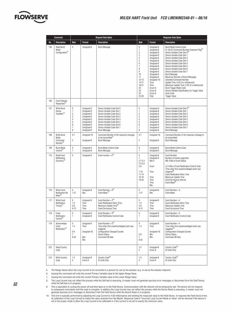
105 Read Burst Mode Configuration34
0 Unsigned-8 Burst Message 0123456789101112-1314-1718-2122232425-28
Unsigned-8Unsigned-8Unsigned-8Unsigned-8Unsigned-8Unsigned-8Unsigned-8Unsigned-8Unsigned-8Unsigned-8Unsigned-8Unsigned-8Unsigned-16TimeTimeEnum-8Enum-8Enum-8Float
Burst Mode Control Code31 (0x1F) Command Number Extension Flag39 Device Variable Code Slot 040 Device Variable Code Slot 1Device Variable Code Slot 2Device Variable Code Slot 3Device Variable Code Slot 4Device Variable Code Slot 5Device Variable Code Slot 6Device Variable Code Slot 7Burst MessageMaximum Number of Burst MessagesExtended Command NumberUpdate Time (1/32 of a millisecond)Maximum Update Time (1/32 of a millisecond)Burst Trigger Mode CodeDevice Variable Classification for Trigger ValueUnits CodeTrigger Value
106 Flush Delayed Responses34
107 Write Burst Device Variables34
012345678
Unsigned-8Unsigned-8Unsigned-8Unsigned-8Unsigned-8Unsigned-8Unsigned-8Unsigned-8Unsigned-8
Device Variable Code Slot 0Device Variable Code Slot 1Device Variable Code Slot 2Device Variable Code Slot 2Device Variable Code Slot 4Device Variable Code Slot 5Device Variable Code Slot 6Device Variable Code Slot 7Burst Message
012345678
Unsigned-8Unsigned-8Unsigned-8Unsigned-8Unsigned-8Unsigned-8Unsigned-8Unsigned-8Unsigned-8
Device Variable Code Slot 040
Device Variable Code Slot 1Device Variable Code Slot 2Device Variable Code Slot 2Device Variable Code Slot 4Device Variable Code Slot 5Device Variable Code Slot 6Device Variable Code Slot 7Burst Message
108 Write Burst Mode Command Number34
0-1
2
Unsigned-16
Unsigned-8
Command Number of the response message to be transmitted41
Burst Message
0-1
2
Unsigned-16
Unsigned-8
Command Number of the response message to be transmittedBurst Message
109 Burst Mode Control42
01
Unsigned-8Unsigned-8
Burst Mode Control CodeBurst Message
01
Unsigned-8Unsigned-8
Burst Mode Control CodeBurst Message
115 Read Event Notification Summary43
0 Unsigned-8 Event number = 044 012.7-2.42.3-2.03-6
7-1011-1415-1819-44
Unsigned-8Unsigned-8Bits-4
Enum
Time
TimeTimeTimeBits
Event NumberNumber of events supportedMS 4 Bits of Event Status
LS 4 Bits of Event Notification Control CodeTime when first unacknowledged event was triggered45
Event Notification Retry TimeMaximum Update TimeEvent De-bounce IntervalEvent Mask46
116 Write Event Notification Bit Mask43
01-27
Unsigned-8Bits
Event Number = 044
Event Mask 4701-27
Unsigned-8Bits
Event Number = 0 Event Mask
117 Write Event Notification Timing43
01-45-89-12
Unsigned-8TimeTimeTime
Event Number = 044
Event Notification Retry Time Maximum Update Time48
Event De-bounce Time
01-45-89-12
Unsigned-8TimeTimeTime
Event Number = 0 Event Notification Retry TimeMaximum Update TimeEvent De-bounce Time
118 Event Notification Control43
01
Unsigned-8Unsigned-8
Event Number = 044
Event Notification Control Code01
Unsigned-8Unsigned-8
Event Number = 0 Event Notification Control Code
119 Acknowledge Event Notification43
01-4
5-678-32
Unsigned-8Time
Unsigned-16
BitsBits
Event Number = 044
Time when first unacknowledged event was triggered Configuration Changed CounterDevice StatusCommand 48 Data
01-4
5-678-32
Unsigned-8Time
Unsigned-16BitsBits
Event Number = 0Time when first unacknowledged event was triggered 49
Configuration Changed CounterDevice StatusCommand 48 Data
512 Read Country Code
1-23
Unsigned-8Enum-8
Country Code50 SI Units Only
513 Write Country Code
1-23
Unsigned-8Enum-8
Country Code50
SI Units Only1-23
Unsigned-8Enum-8
Country Code50
SI Units Only
5. The Range Values allow the Loop Current to be converted to a percent for use by the actuator (e.g. to use as the actuator setpoint).6. Issuing this command will write the current Primary Variable value to the Upper Range Value.7. Issuing this command will write the current Primary Variable value to the Lower Range Value.8. The Loop Current may not reflect the process while the Self test is executing. A master must not generate spurious error messages or disconnect form the Field Device
while the Self test is in progress.9. This is equivalent to cycling the power off and then back on to the Field Device. Communication with the network will be temporarily lost. The device will not respond
to subsequent commands until the reset is complete. In addition the Loop Current may not reflect the process while the Device Reset is executing. A master must not generate spurious error messages or disconnect from the Field Device while the Device Reset is in progress.
10. This trim is typically performed by adjusting the Loop Current to 4.00 milliamperes and sending the measured value to the Field Device. In response the Field Device trims its calibration of the Loop Current to match the value received from the Master. Response Code 9 “Incorrect Loop Current Mode or Value” will be returned if the device is not in the proper mode to allow the Loop Current to be calibrated or if the current is not set to exactly the minimum value.
33
MX/QX HART Field Unit FCD LMENIM2340-01 – 06/16
flowserve.com
11. The value returned in the response data bytes reflects the rounded or truncated value actually used by the device for the Zero value.12. This trim is typically performed by adjusting the Loop Current to 20.00 milliamperes and sending the measured value to the Field Device. In response the Field Device
trims its calibration of the Loop Current to match the value received from the Master. Response Code 9 “Incorrect Loop Current Mode or Value” will be returned if the device is not in the proper mode to allow the Loop Current to be calibrated or if the current is not set to exactly the maximum value.
13. The value returned in the response data bytes reflects the rounded or truncated value actually used by the device for the Gain value.14. Command 56 write device variable transducer serial number can also be used to write the PV transducer serial number if device variable code 0 (position setpoint) is
used.15. See Section 3.4 Device Variables for more information on Device Variables and mapping. Note: the Device Variable Assignment is made by the Device Variable Code
(0-4).16. Note: only Device Variables 3 and 4 may have their units code changed. See 3.4.3 Device Variable Units for more information. Response Code 11 “Invalid Device Variable
Code” will be returned if an invalid Device Variable Code is requested (Device Variable codes 0-4). Response Code 12 “Invalid Units Code” will be returned if the units code is not valid for the given Device Variable Code.
17. The update time period indicates the maximum period between Device Variable updates.18. This command sets the number of asynchronous 0xFF preamble bytes to be sent by a device before the start of a response message. This value may be set to no smaller
than 5 and no greater than 20.19. There is one analog channel with analog channel number code of 0 which is linked to the Primary Variable.20. Percent of Range always follows the Analog Level even if it is set to a value. The Upper and Lower Range Values maps the Analog Level to the percent of Range. As a
result the Percent of Range is not limited to values between 0% and 100%, but tracks the Analog Level to Transducer Limits when they are defined.21 The Upper Range Value may be set lower than the Lower Range Value, enabling the device to be operated with a reversed signaling polarity.22. A level containing NAN or “0x7F, 0xA0, 0x00, 0x00”, with any units code exits the fixed analog channel mode. The device will also exit fixed analog channel mode when
power is removed from the device or the device is reset.23. The value returned in the response data bytes reflects the rounded or truncated value actually used by the device.24. This command can be used to receive multiple read commands in one read for faster command reads.25. Normally a host should send this command multiple times while measuring average latency. Each time the host will adjust the Time of Day value compensating for the
communication latency. This will be repeated until communication latency affects are characterized and its effect on setting the real time clock is minimized.26. See Appendix D for additional details on how this command works dependent upon this code.27. Should be set to 0, Two bytes to ensure request and response take equal amounts of time (compensates for transmission time of Response Code and Device Status in
response).28. Reads the real time clock including the current time as estimated by the device and the last time the clock was set. The device must answer with the internal time at which
the request was received. If the clock has not been set then the last time set must be initialized to midnight (00:00) 01 January, 1900.29. See section “3.2 HART Parameters” for maximum number of trends and trend buffer size. 30. Maximum is 2 hour; one trend per day i.e. 0x0DBBA00031. When a change in configuration is detected (change of Trend Control Code, Device Variable or Update Interval), the device will clear the ring buffer and initialize all values
to NaN (0x7FA00000) and the status set to BAD-Fixed (0x30) before starting the trend.32. When the trend is not enabled the device shall return the data last collected with the corresponding date and time. The Response Code shall be set to 8 – Trend not
Active.33. The communications statistics are volatile and reset to zero only on power-up or board reset. All counts must wrap to zero on overflow.34. Please see sections “3.5.3 Burst Messages” for configuration details of Burst Mode.35. In 1/32 of a millisecond - Update period must not exceed 3600 seconds. The device must publish data at this rate as long as the trigger conditions in command 104 are
met.36. In 1/32 of a millisecond – Maximum update period must not exceed 3600 seconds. The device must publish at this rate when the trigger conditions configured in
command 104 are not met.37. The value returned in the response data bytes reflects the value actually used by the device. If the update time had to be adjusted by the device, the response will reflect
the adjusted value. See section “3.5.3 Burst Messages” for more information about update rates.38. If command 2 “Read Loop Current and Percent of Range” is selected the Device Variable Classification must be 0 and the Engineering Units “Percent” (0x39 or
57 decimal).39. Note: if there are no request data bytes then this byte must return the LS Byte of the burst command number.40. If a slot is not configured to transmit a Device Variable that slot must return “250” not used. If command 9 is to be burst then the slot’s Device Variable Code must meet
the requirements found in command 9.41. See section “3.5.3 Burst Messages” for a list of commands supported for Burst Messaging. Note: if the trigger mode is non-zero in command 104 (not Continuous) and
the trigger source’s Device Variable Classification does not match for the new command number the new command number will be accepted and Response Code 8 “Burst Condition Conflict” will be returned. The HART device shall correct the classification, correct the unit codes, and reset the trigger mode to 0 (Continuous) and publish continuously at the update period until it receives another command 104.
42. See section “3.5.3 Burst Messages” for more information on configuring Burst Messages. Note: This command affects Data Link Layer operation. All Data Link Layer requirements for entering and exiting burst mode must be met.
43. See section “3.5.4 Event Notification” for more information about Event Notifications.44. The MX/QX Hart device supports one Event Notification which is identified as Event Notification Number 0.45. The value shall be set to 0xFFFFFFFF when no events are pending.46. This is the concatenation of the mask for triggering on bits set in Device Status and Command 48 Response. The command can be truncated after the last byte in the
Event Mask. 47. The concatenation of the mask for triggering on bits set in Device Status and Command 48 Response. The request is truncated after the last byte containing a trigger-able
event. Bytes that are truncated assume a bit mask value of zero. Therefore, any byte not included shall not trigger an event notification. Furthermore, the truncated bytes shall not be included in the notification generated using the command 119 response.
48. The return and update times must be selected as specified in section “3.5.4.3 Update Periods”. The retry period must be less than or equal to the maximum update period.
49. Value will be set to -1 when no events are pending.50. The two letter country code in accordance with ISO.
3.5.3 Burst Messages
In this mode, the Limitorque MX/QX field device will publish the response to a command continuously without any further Master or Host action. All masters must arbitrate correctly when a burst-mode field device is present on the loop.
MX/QX HART Field Unit FCD LMENIM2340-01 – 06/16
34
There must be only one burst mode device active on the communication link at any given time. This is because the Master must adapt its operation to ensure correct bus arbitration, because the token passing sequence is fundamentally changed.
3.5.3.1 Update Periods
The host application or control system may set the update periods for the Limitorque MX/QX field device to the following allowed values: 0.5, 1.0, 2.0, 4.0, 8.0, 16.0, 32.0, and 60-3600 seconds.
If a setting is requested that is different from those indicated above, the HART device must correct the setting and send response code 8 “Update Times Adjusted” in its response message. The update time returned in the response message will reflect the adjusted update time the device is using.
When enabling burst messaging, the device takes control of the Token Passing Layer bursting out the default burst message with no less than “Link Grant Time” (approximately 75 ms) between bursts. This Link Grant Time allows another master to take over the bus and transmit a message. If only one burst message is enabled, it is the default burst message. If more than one burst message is enabled, the burst message with the shortest update period is the default burst message.
On a Token Passing Data-Link burst, messages are used both to publish data and to pass the token. Therefore, the default burst message will always burst with approximately 75 ms between bursts, regardless of what value is set for the “Update Period” of the default burst message. If more than one burst message is enabled, the other (not default) burst messages will be burst based on their Update and Max Update Periods.
3.5.3.2 Commands Supported for Burst Message• Command 1 Read Primary Variable• Command 2 Read Loop Current and Percent of Range• Command 3 Read Dynamic Variables and Loop Current• Command 9 Read Device Variables With Status• Command 33 Read Device Variables • Command 48 Read Additional Device Status• Command 93 Read Trend
3.5.3.3 Configuring a Device for Burst Mode Operation
Burst messages can be configured from the DD menu Device Setup->Wired Hart Board->Configuration->Burst Messages as follows:
35
MX/QX HART Field Unit FCD LMENIM2340-01 – 06/16
flowserve.com
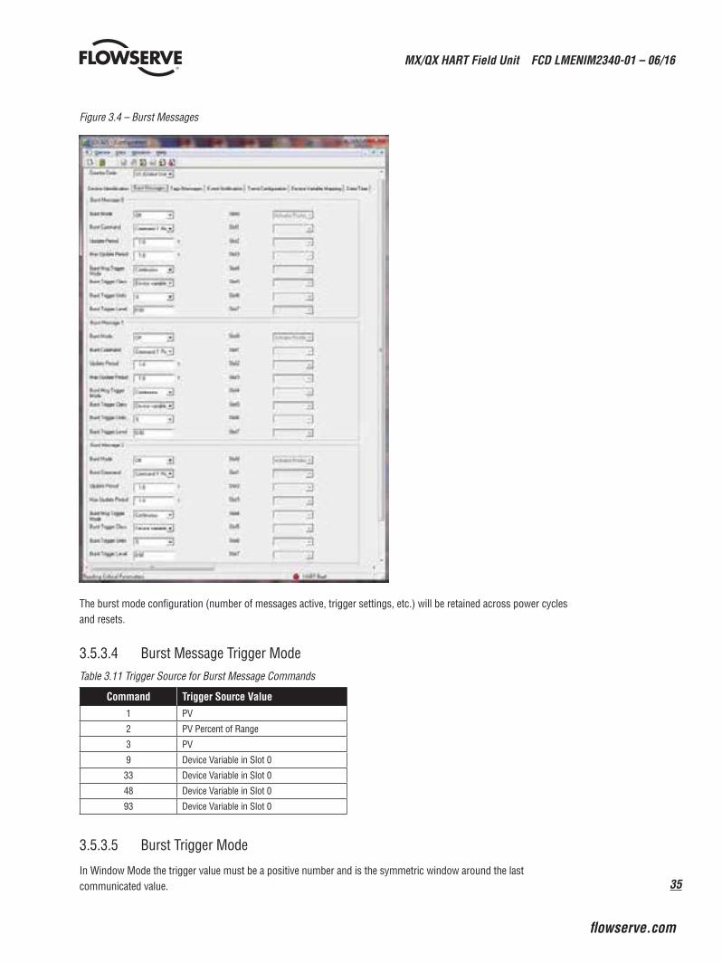
Figure 3.4 – Burst Messages
The burst mode configuration (number of messages active, trigger settings, etc.) will be retained across power cycles and resets.
3.5.3.4 Burst Message Trigger ModeTable 3.11 Trigger Source for Burst Message Commands
Command Trigger Source Value1 PV
2 PV Percent of Range
3 PV
9 Device Variable in Slot 0
33 Device Variable in Slot 0
48 Device Variable in Slot 0
93 Device Variable in Slot 0
3.5.3.5 Burst Trigger Mode
In Window Mode the trigger value must be a positive number and is the symmetric window around the last communicated value.
MX/QX HART Field Unit FCD LMENIM2340-01 – 06/16
36
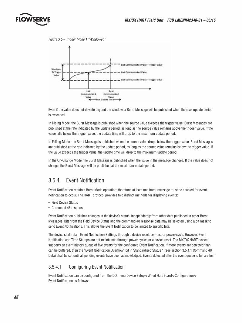
Figure 3.5 – Trigger Mode 1 “Windowed”
Even if the value does not deviate beyond the window, a Burst Message will be published when the max update period is exceeded.
In Rising Mode, the Burst Message is published when the source value exceeds the trigger value. Burst Messages are published at the rate indicated by the update period, as long as the source value remains above the trigger value. If the value falls below the trigger value, the update time will drop to the maximum update period.
In Falling Mode, the Burst Message is published when the source value drops below the trigger value. Burst Messages are published at the rate indicated by the update period, as long as the source value remains below the trigger value. If the value exceeds the trigger value, the update time will drop to the maximum update period.
In the On-Change Mode, the Burst Message is published when the value in the message changes. If the value does not change, the Burst Message will be published at the maximum update period.
3.5.4 Event Notification
Event Notification requires Burst Mode operation; therefore, at least one burst message must be enabled for event notification to occur. The HART protocol provides two distinct methods for displaying events:
• Field Device Status• Command 48 response
Event Notification publishes changes in the device’s status, independently from other data published in other Burst Messages. Bits from the Field Device Status and the command 48 response data may be selected using a bit mask to send Event Notifications. This allows the Event Notification to be limited to specific bits.
The device shall retain Event Notification Settings through a device reset, self-test or power-cycle. However, Event Notification and Time Stamps are not maintained through power cycles or a device reset. The MX/QX HART device supports an event history queue of five events for the configured Event Notification. If more events are detected than can be buffered, then the “Event Notification Overflow” bit in Standardized Status 1 (see section 3.5.1.1 Command 48 Data) shall be set until all pending events have been acknowledged. Events detected after the event queue is full are lost.
3.5.4.1 Configuring Event Notification
Event Notification can be configured from the DD menu Device Setup->Wired Hart Board->Configuration-> Event Notification as follows:
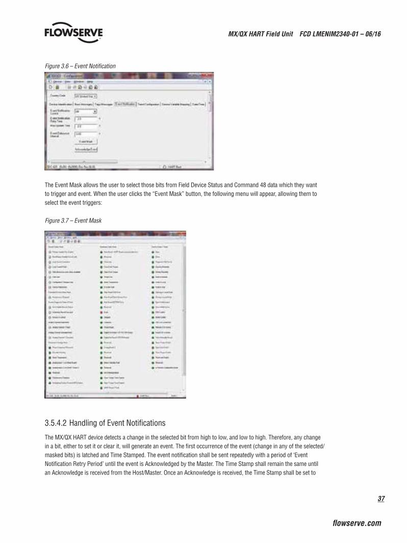
37
MX/QX HART Field Unit FCD LMENIM2340-01 – 06/16
flowserve.com
Figure 3.6 – Event Notification
The Event Mask allows the user to select those bits from Field Device Status and Command 48 data which they want to trigger and event. When the user clicks the “Event Mask” button, the following menu will appear, allowing them to select the event triggers:
Figure 3.7 – Event Mask
3.5.4.2 Handling of Event Notifications
The MX/QX HART device detects a change in the selected bit from high to low, and low to high. Therefore, any change in a bit, either to set it or clear it, will generate an event. The first occurrence of the event (change in any of the selected/masked bits) is latched and Time Stamped. The event notification shall be sent repeatedly with a period of ‘Event Notification Retry Period’ until the event is Acknowledged by the Master. The Time Stamp shall remain the same until an Acknowledge is received from the Host/Master. Once an Acknowledge is received, the Time Stamp shall be set to
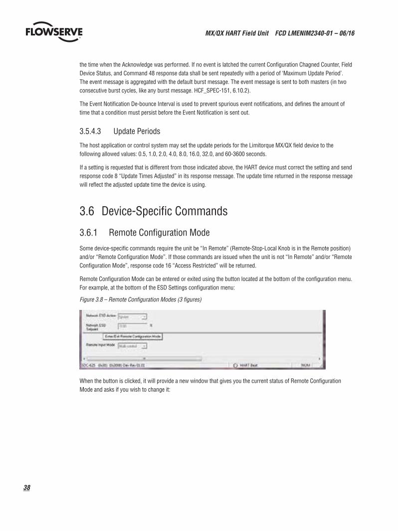
MX/QX HART Field Unit FCD LMENIM2340-01 – 06/16
38
the time when the Acknowledge was performed. If no event is latched the current Configuration Chagned Counter, Field Device Status, and Command 48 response data shall be sent repeatedly with a period of ‘Maximum Update Period’. The event message is aggregated with the default burst message. The event message is sent to both masters (in two consecutive burst cycles, like any burst message. HCF_SPEC-151, 6.10.2).
The Event Notification De-bounce Interval is used to prevent spurious event notifications, and defines the amount of time that a condition must persist before the Event Notification is sent out.
3.5.4.3 Update Periods
The host application or control system may set the update periods for the Limitorque MX/QX field device to the following allowed values: 0.5, 1.0, 2.0, 4.0, 8.0, 16.0, 32.0, and 60-3600 seconds.
If a setting is requested that is different from those indicated above, the HART device must correct the setting and send response code 8 “Update Times Adjusted” in its response message. The update time returned in the response message will reflect the adjusted update time the device is using.
3.6 Device-Specific Commands
3.6.1 Remote Configuration Mode
Some device-specific commands require the unit be “In Remote” (Remote-Stop-Local Knob is in the Remote position) and/or “Remote Configuration Mode”. If those commands are issued when the unit is not “In Remote” and/or “Remote Configuration Mode”, response code 16 “Access Restricted” will be returned.
Remote Configuration Mode can be entered or exited using the button located at the bottom of the configuration menu. For example, at the bottom of the ESD Settings configuration menu:
Figure 3.8 – Remote Configuration Modes (3 figures)
When the button is clicked, it will provide a new window that gives you the current status of Remote Configuration Mode and asks if you wish to change it:
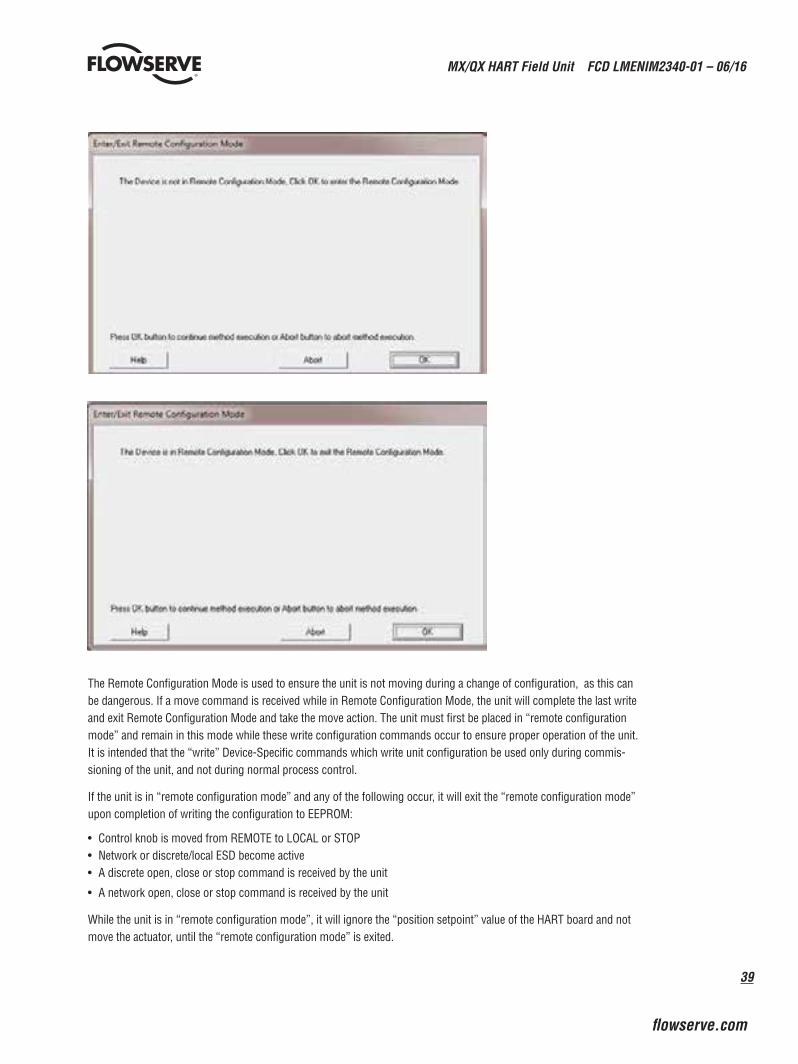
39
MX/QX HART Field Unit FCD LMENIM2340-01 – 06/16
flowserve.com
The Remote Configuration Mode is used to ensure the unit is not moving during a change of configuration, as this can be dangerous. If a move command is received while in Remote Configuration Mode, the unit will complete the last write and exit Remote Configuration Mode and take the move action. The unit must first be placed in “remote configuration mode” and remain in this mode while these write configuration commands occur to ensure proper operation of the unit. It is intended that the “write” Device-Specific commands which write unit configuration be used only during commis-sioning of the unit, and not during normal process control.
If the unit is in “remote configuration mode” and any of the following occur, it will exit the “remote configuration mode” upon completion of writing the configuration to EEPROM:
• Control knob is moved from REMOTE to LOCAL or STOP• Network or discrete/local ESD become active• A discrete open, close or stop command is received by the unit
• A network open, close or stop command is received by the unit
While the unit is in “remote configuration mode”, it will ignore the “position setpoint” value of the HART board and not move the actuator, until the “remote configuration mode” is exited.
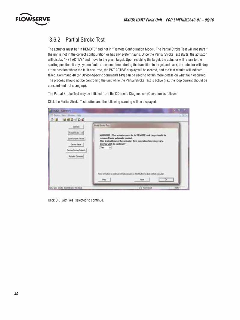
MX/QX HART Field Unit FCD LMENIM2340-01 – 06/16
40
3.6.2 Partial Stroke Test
The actuator must be “in REMOTE” and not in “Remote Configuration Mode”. The Partial Stroke Test will not start if the unit is not in the correct configuration or has any system faults. Once the Partial Stroke Test starts, the actuator will display “PST ACTIVE” and move to the given target. Upon reaching the target, the actuator will return to the starting position. If any system faults are encountered during the transition to target and back, the actuator will stop at the position where the fault occurred, the PST ACTIVE display will be cleared, and the test results will indicate failed. Command 48 (or Device-Specific command 149) can be used to obtain more details on what fault occurred. The process should not be controlling the unit while the Partial Stroke Test is active (i.e., the loop current should be constant and not changing).
The Partial Stroke Test may be initiated from the DD menu Diagnostics->Operation as follows:
Click the Partial Stroke Test button and the following warning will be displayed:
Click OK (with Yes) selected to continue.
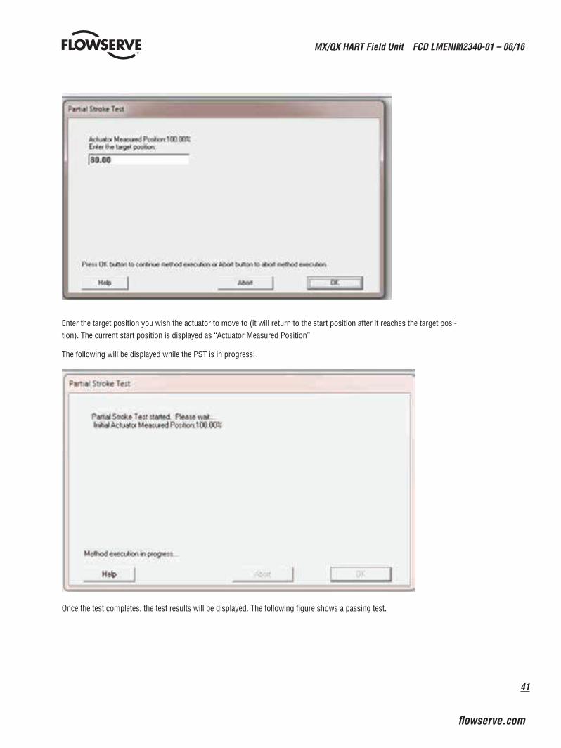
41
MX/QX HART Field Unit FCD LMENIM2340-01 – 06/16
flowserve.com
Enter the target position you wish the actuator to move to (it will return to the start position after it reaches the target posi-tion). The current start position is displayed as “Actuator Measured Position”
The following will be displayed while the PST is in progress:
Once the test completes, the test results will be displayed. The following figure shows a passing test.
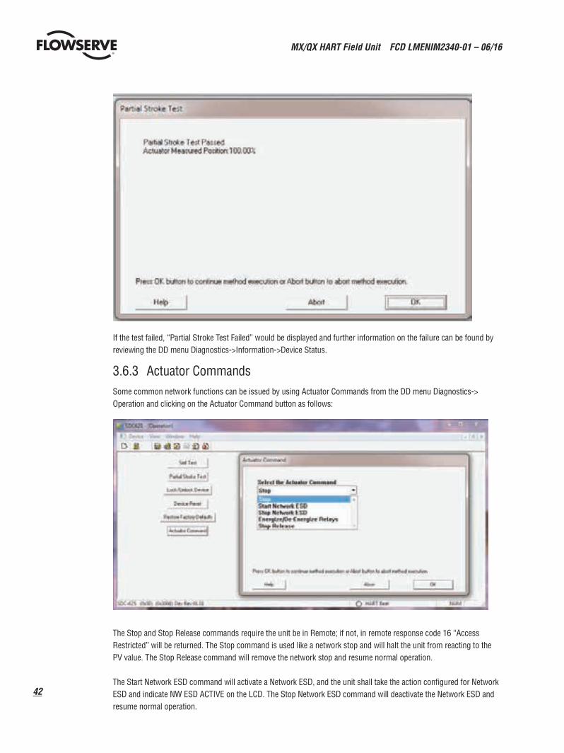
MX/QX HART Field Unit FCD LMENIM2340-01 – 06/16
42
If the test failed, “Partial Stroke Test Failed” would be displayed and further information on the failure can be found by reviewing the DD menu Diagnostics->Information->Device Status.
3.6.3 Actuator CommandsSome common network functions can be issued by using Actuator Commands from the DD menu Diagnostics-> Operation and clicking on the Actuator Command button as follows:
The Stop and Stop Release commands require the unit be in Remote; if not, in remote response code 16 “Access Restricted” will be returned. The Stop command is used like a network stop and will halt the unit from reacting to the PV value. The Stop Release command will remove the network stop and resume normal operation.
The Start Network ESD command will activate a Network ESD, and the unit shall take the action configured for Network ESD and indicate NW ESD ACTIVE on the LCD. The Stop Network ESD command will deactivate the Network ESD and resume normal operation.
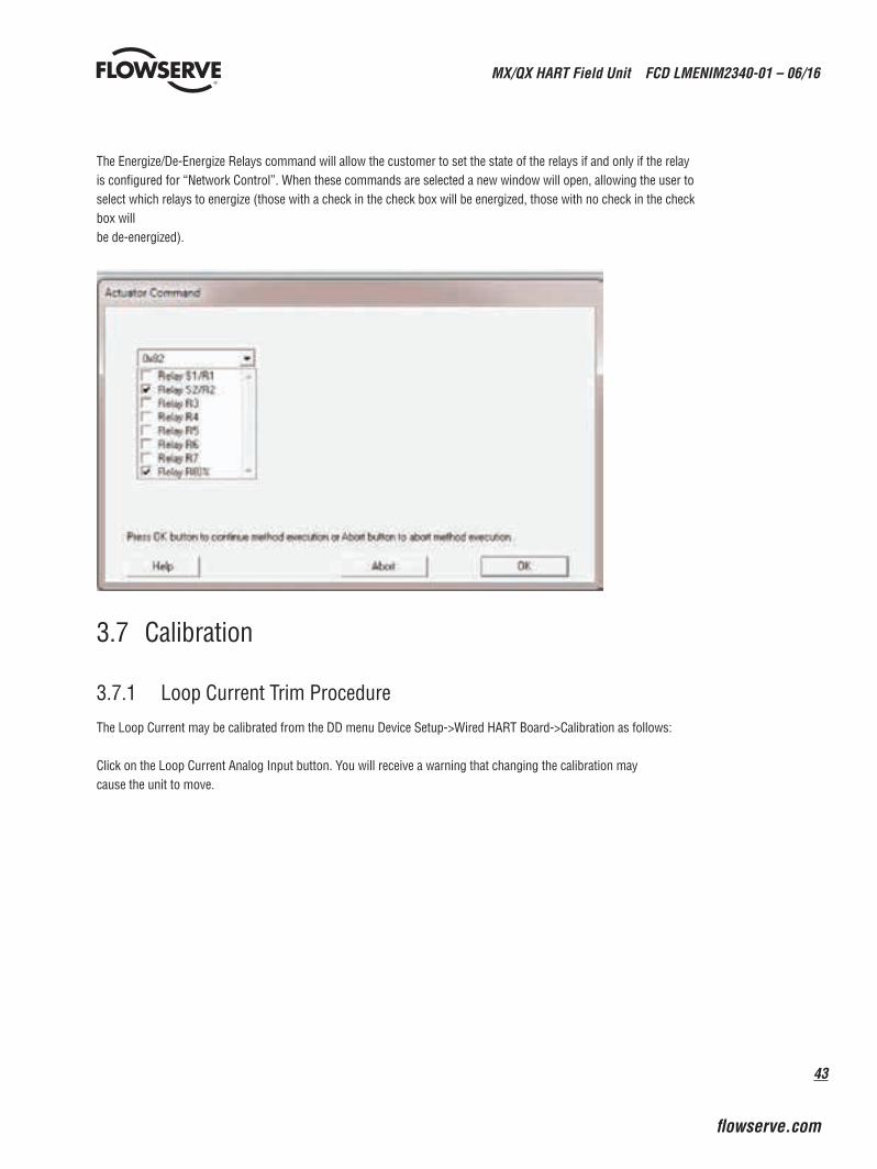
43
MX/QX HART Field Unit FCD LMENIM2340-01 – 06/16
flowserve.com
The Energize/De-Energize Relays command will allow the customer to set the state of the relays if and only if the relay is configured for “Network Control”. When these commands are selected a new window will open, allowing the user to select which relays to energize (those with a check in the check box will be energized, those with no check in the check box will be de-energized).
3.7 Calibration
3.7.1 Loop Current Trim Procedure
The Loop Current may be calibrated from the DD menu Device Setup->Wired HART Board->Calibration as follows:
Click on the Loop Current Analog Input button. You will receive a warning that changing the calibration may cause the unit to move.
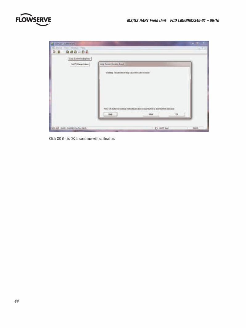
MX/QX HART Field Unit FCD LMENIM2340-01 – 06/16
44
Click OK if it is OK to continue with calibration.
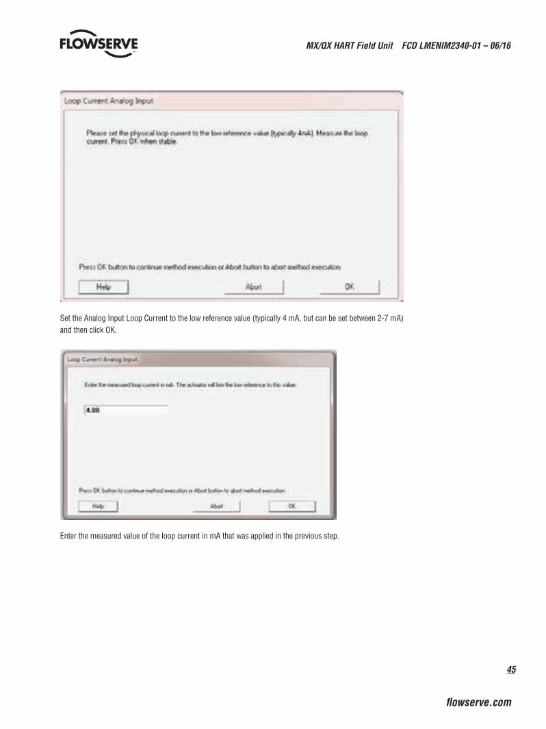
45
MX/QX HART Field Unit FCD LMENIM2340-01 – 06/16
flowserve.com
Set the Analog Input Loop Current to the low reference value (typically 4 mA, but can be set between 2-7 mA) and then click OK.
Enter the measured value of the loop current in mA that was applied in the previous step.
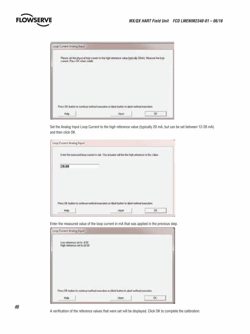
MX/QX HART Field Unit FCD LMENIM2340-01 – 06/16
46
Set the Analog Input Loop Current to the high reference value (typically 20 mA, but can be set between 12-28 mA) and then click OK.
Enter the measured value of the loop current in mA that was applied in the previous step.
A verification of the reference values that were set will be displayed. Click OK to complete the calibration.
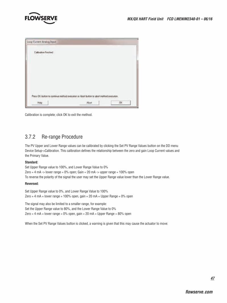
47
MX/QX HART Field Unit FCD LMENIM2340-01 – 06/16
flowserve.com
Calibration is complete; click OK to exit the method.
3.7.2 Re-range Procedure
The PV Upper and Lower Range values can be calibrated by clicking the Set PV Range Values button on the DD menu Device Setup->Calibration. This calibration defines the relationship between the zero and gain Loop Current values and the Primary Value.
Standard:Set Upper Range value to 100%, and Lower Range Value to 0%Zero = 4 mA -> lower range = 0% open; Gain = 20 mA -> upper range = 100% openTo reverse the polarity of the signal the user may set the Upper Range value lower than the Lower Range value.
Reversed:
Set Upper Range value to 0%, and Lower Range Value to 100%Zero = 4 mA = lower range = 100% open, gain = 20 mA = Upper Range = 0% open
The signal may also be limited to a smaller range, for example:Set the Upper Range value to 80%, and the Lower Range Value to 0%Zero = 4 mA = lower range = 0% open, gain = 20 mA = Upper Range = 80% open
When the Set PV Range Values button is clicked, a warning is given that this may cause the actuator to move:
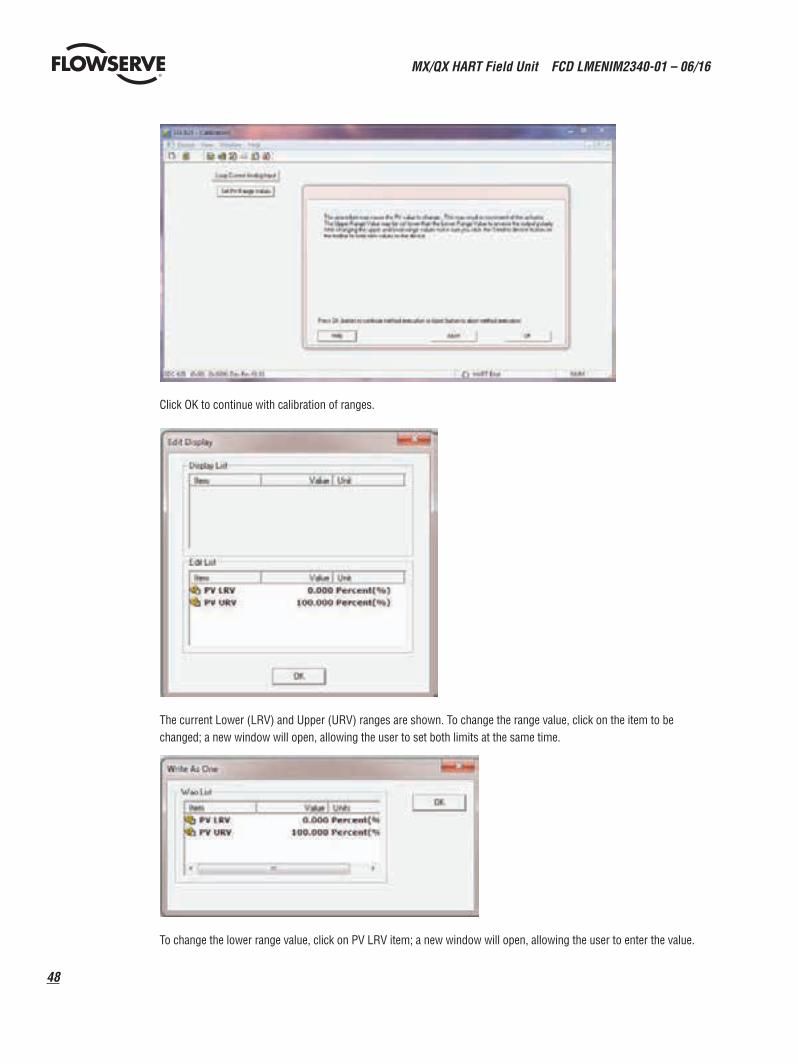
MX/QX HART Field Unit FCD LMENIM2340-01 – 06/16
48
Click OK to continue with calibration of ranges.
The current Lower (LRV) and Upper (URV) ranges are shown. To change the range value, click on the item to be changed; a new window will open, allowing the user to set both limits at the same time.
To change the lower range value, click on PV LRV item; a new window will open, allowing the user to enter the value.
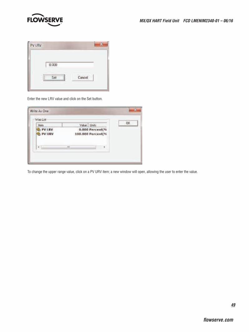
49
MX/QX HART Field Unit FCD LMENIM2340-01 – 06/16
flowserve.com
Enter the new LRV value and click on the Set button.
To change the upper range value, click on a PV URV item; a new window will open, allowing the user to enter the value.
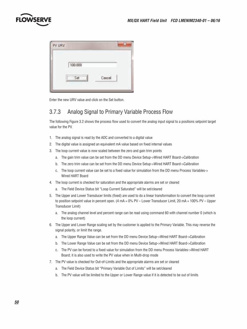
MX/QX HART Field Unit FCD LMENIM2340-01 – 06/16
50
Enter the new URV value and click on the Set button.
3.7.3 Analog Signal to Primary Variable Process Flow
The following Figure 3.2 shows the process flow used to convert the analog input signal to a positions setpoint target value for the PV.
1. The analog signal is read by the ADC and converted to a digital value
2. The digital value is assigned an equivalent mA value based on fixed internal values
3. The loop current value is now scaled between the zero and gain trim points
a. The gain trim value can be set from the DD menu Device Setup->Wired HART Board->Calibration
b. The zero trim value can be set from the DD menu Device Setup->Wired HART Board->Calibration
c. The loop current value can be set to a fixed value for simulation from the DD menu Process Variables-> Wired HART Board
4. The loop current is checked for saturation and the appropriate alarms are set or cleared
a. The Field Device Status bit “Loop Current Saturated” will be set/cleared
5. The Upper and Lower Transducer limits (fixed) are used to do a linear transformation to convert the loop current to position setpoint value in percent open. (4 mA = 0% PV – Lower Transducer Limit, 20 mA = 100% PV – Upper Transducer Limit)
a. The analog channel level and percent range can be read using command 60 with channel number 0 (which is the loop current)
6. The Upper and Lower Range scaling set by the customer is applied to the Primary Variable. This may reverse the signal polarity, or limit the range.
a. The Upper Range Value can be set from the DD menu Device Setup->Wired HART Board->Calibration
b. The Lower Range Value can be set from the DD menu Device Setup->Wired HART Board->Calibration
c. The PV can be forced to a fixed value for simulation from the DD menu Process Variables->Wired HART Board; it is also used to write the PV value when in Multi-drop mode
7. The PV value is checked for Out-of-Limits and the appropriate alarms are set or cleared
a. The Field Device Status bit “Primary Variable Out of Limits” will be set/cleared
b. The PV value will be limited to the Upper or Lower Range value if it is detected to be out of limits

51
MX/QX HART Field Unit FCD LMENIM2340-01 – 06/16
flowserve.com
8. The PV value is now ready to be used in the process
a. Command 1 can be used to read the primary variable
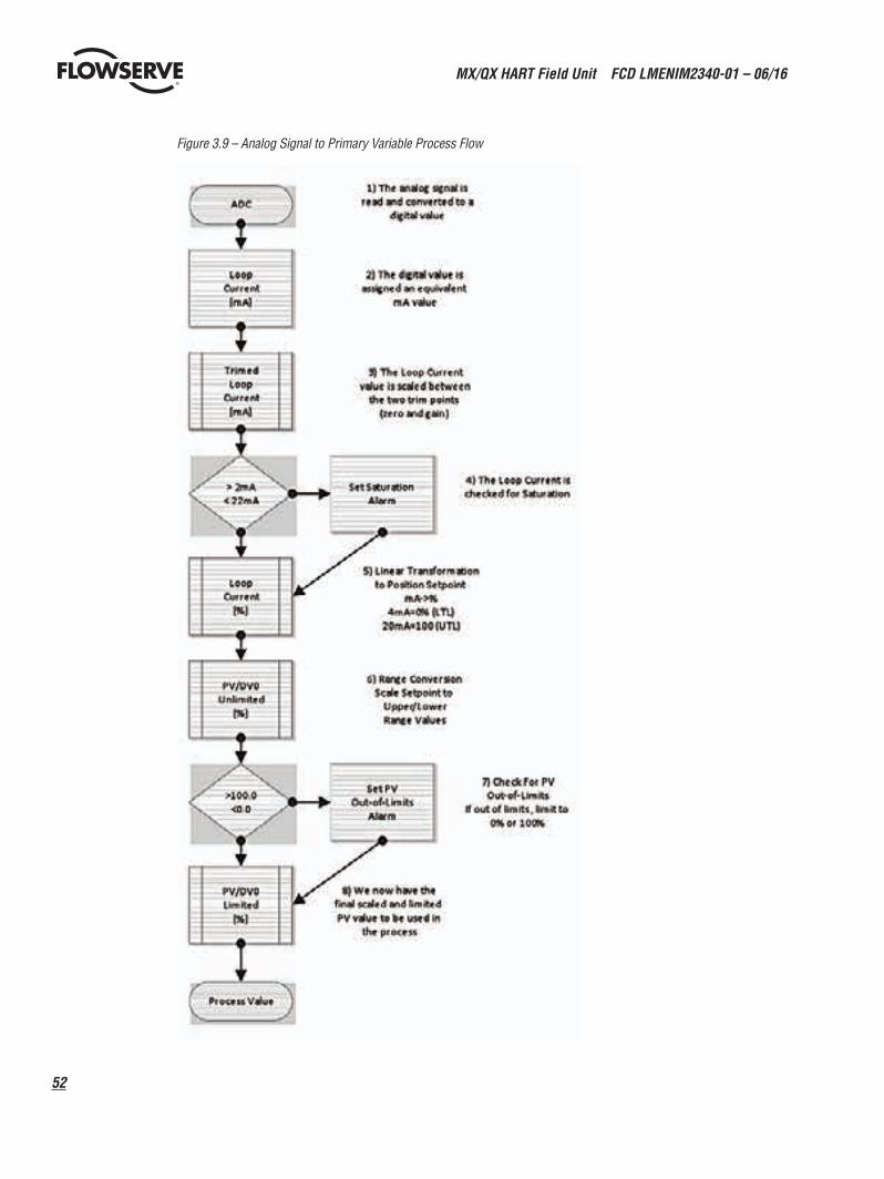
MX/QX HART Field Unit FCD LMENIM2340-01 – 06/16
52
Figure 3.9 – Analog Signal to Primary Variable Process Flow
53
MX/QX HART Field Unit FCD LMENIM2340-01 – 06/16
flowserve.com
4 Associated Documents
MX/QX FOUNDATION Fieldbus Field Unit FCD LMENIM2330-01 – 08/11
40
4 Associated Documents
Additional information can be found in the following documents:
MX Actuator
Quick Start-Up Instructions (MX Actuators) Limitorque Bulletin LMENIM2310
MX Installation and Operation Manual Limitorque Bulletin LMENIM2306
Protection, Control and Monitoring Features of MX Electric Actuators
Limitorque Bulletin LMENTB2300
MX Maintenance and Spare Parts Manual Limitorque Bulletin LMENIM2314
QX Actuator
Quick Start-Up Instructions (QX Actuators) Limitorque Bulletin LMENIM3313
QX Installation and Operation Manual Limitorque Bulletin LMENIM3306
Protection, Control and Monitoring Features of QX Electric Actuator
Limitorque Bulletin LMENIM2300
QX Maintenance and Spare Parts Manual Limitorque Bulletin LMENIM3314
Fieldbus
Foundation fieldbus Technical Overview Foundation fieldbus FD-043
Foundation fieldbus Wiring and Installation 31.25 kbits/s, Voltage Mode, Wire Medium, Application Guide
Foundation fieldbus AG-140
Foundation Specification. Function Block Application Process (Part 1)
Foundation fieldbus FF-890
Foundation Specification. Function Block Application Process (Part 2)
Foundation fieldbus FF-891
Foundation Specification. Transducer Block Application Process (Part 2) Revision PS 3.0, Date: 12 April, 1998
Foundation fieldbus FF-903
FOUNDATION fieldbus documentation is available at http://www.fieldbus.org
5 How to Order Parts
MX/QX HART Field Unit FCD LMENIM2340-01 – 06/16
54
41
MX/QX FOUNDATION Fieldbus Field Unit FCD LMENIM2330-01 – 08/11
flowserve.com
5 How to Order Parts
To order parts or obtain further information about your Limitorque MX/QX HART field unit, contact your local Limitorque distributor sales office, or:
FLOWSERVE CORPORATION FLOW CONTROL DIVISION,
Limitorque Actuation Systems 5114 Woodall Road P.O.Box 11318 Lynchburg, VA 24506-1318
Phone (434) 528-4400 Fax (434) 845-9736
To find the Limitorque distributor or sales office near you, go to http://www.limitorque.com
All inquiries or orders must be accompanied by the following information supplied on the actuator nameplate:
1. Unit size
2. Order number
3. Serial number

55
MX/QX HART Field Unit FCD LMENIM2340-01 – 06/16
flowserve.com
Appendix A – Wiring Diagrams
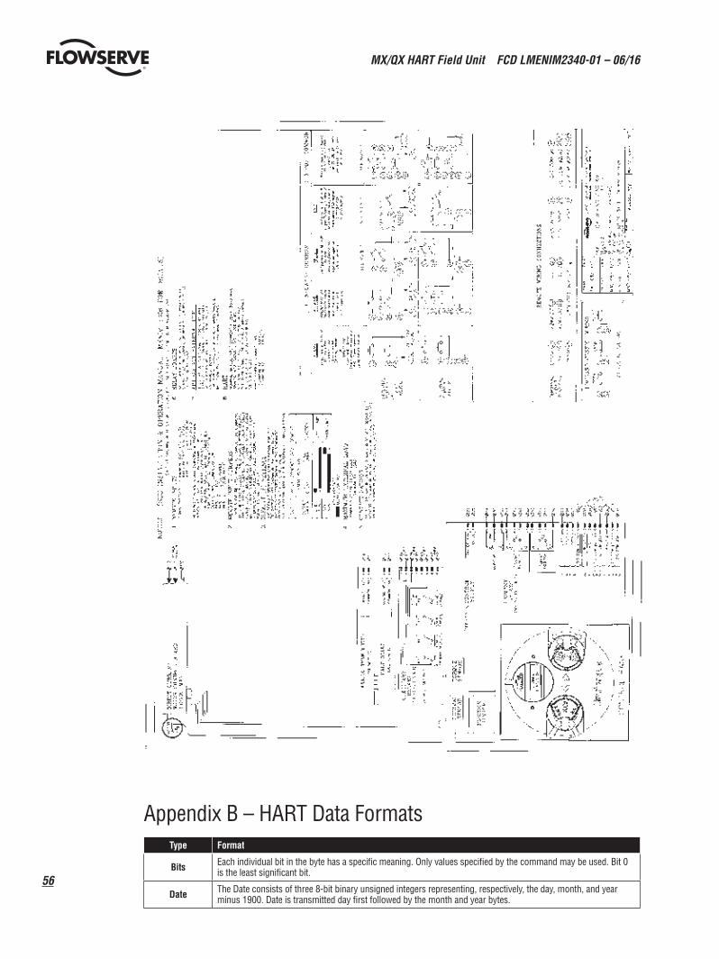
MX/QX HART Field Unit FCD LMENIM2340-01 – 06/16
56
Appendix B – HART Data FormatsType Format
Bits Each individual bit in the byte has a specific meaning. Only values specified by the command may be used. Bit 0 is the least significant bit.
Date The Date consists of three 8-bit binary unsigned integers representing, respectively, the day, month, and year minus 1900. Date is transmitted day first followed by the month and year bytes.
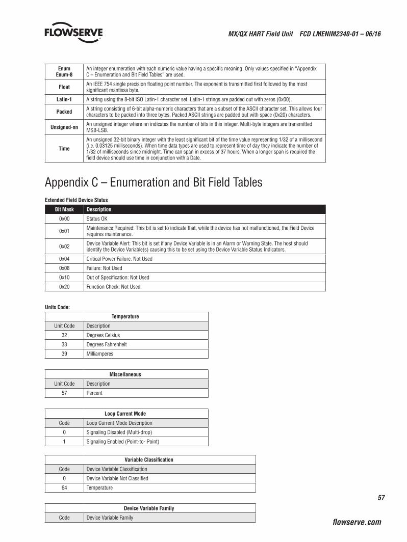
57
MX/QX HART Field Unit FCD LMENIM2340-01 – 06/16
flowserve.com
Enum Enum-8
An integer enumeration with each numeric value having a specific meaning. Only values specified in “Appendix C – Enumeration and Bit Field Tables” are used.
Float An IEEE 754 single precision floating point number. The exponent is transmitted first followed by the most significant mantissa byte.
Latin-1 A string using the 8-bit ISO Latin-1 character set. Latin-1 strings are padded out with zeros (0x00).
Packed A string consisting of 6-bit alpha-numeric characters that are a subset of the ASCII character set. This allows four characters to be packed into three bytes. Packed ASCII strings are padded out with space (0x20) characters.
Unsigned-nn An unsigned integer where nn indicates the number of bits in this integer. Multi-byte integers are transmitted MSB-LSB.
Time
An unsigned 32-bit binary integer with the least significant bit of the time value representing 1/32 of a millisecond (i.e. 0.03125 milliseconds). When time data types are used to represent time of day they indicate the number of 1/32 of milliseconds since midnight. Time can span in excess of 37 hours. When a longer span is required the field device should use time in conjunction with a Date.
Appendix C – Enumeration and Bit Field TablesExtended Field Device Status
Bit Mask Description
0x00 Status OK
0x01 Maintenance Required: This bit is set to indicate that, while the device has not malfunctioned, the Field Device requires maintenance.
0x02 Device Variable Alert: This bit is set if any Device Variable is in an Alarm or Warning State. The host should identify the Device Variable(s) causing this to be set using the Device Variable Status Indicators.
0x04 Critical Power Failure: Not Used
0x08 Failure: Not Used
0x10 Out of Specification: Not Used
0x20 Function Check: Not Used
Units Code:
Temperature
Unit Code Description
32 Degrees Celsius
33 Degrees Fahrenheit
39 Milliamperes
Miscellaneous
Unit Code Description
57 Percent
Loop Current Mode
Code Loop Current Mode Description
0 Signaling Disabled (Multi-drop)
1 Signaling Enabled (Point-to- Point)
Variable Classification
Code Device Variable Classification
0 Device Variable Not Classified
64 Temperature
Device Variable Family
Code Device Variable Family
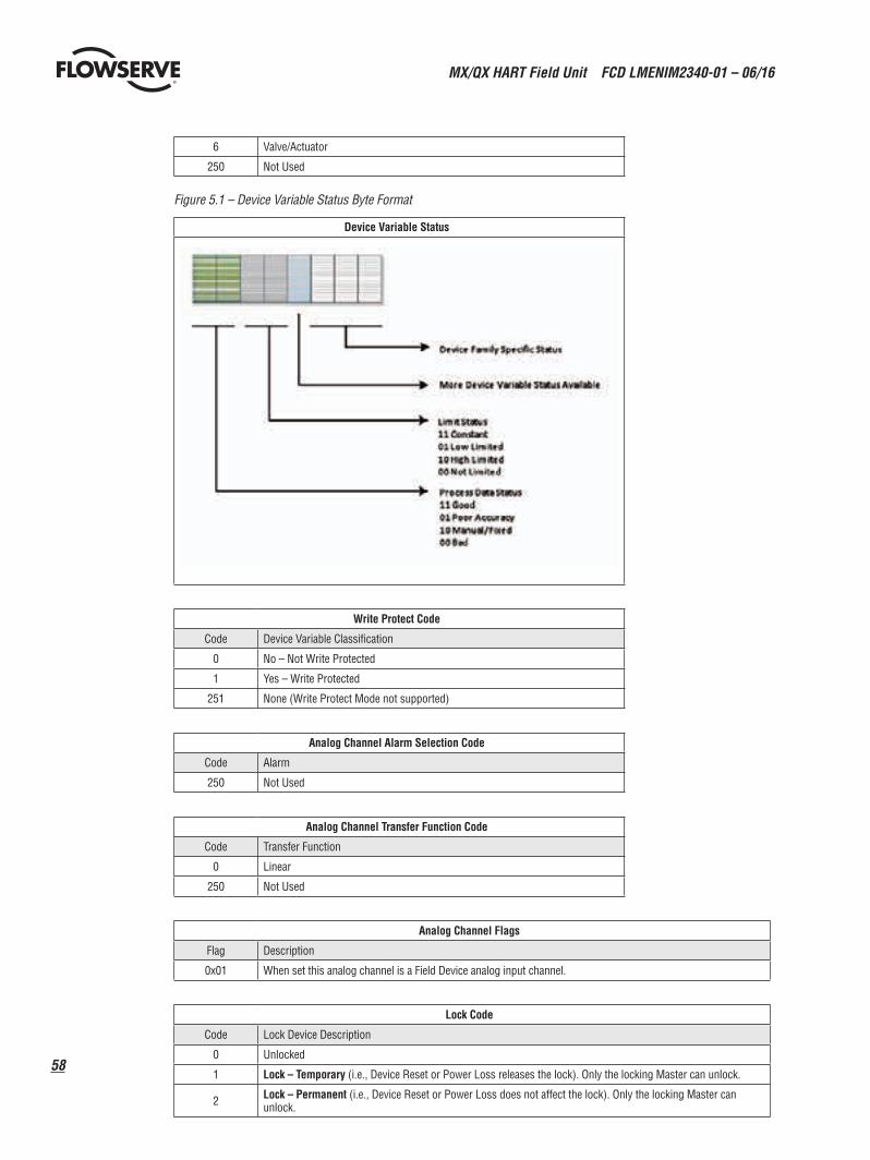
MX/QX HART Field Unit FCD LMENIM2340-01 – 06/16
58
6 Valve/Actuator
250 Not Used
Figure 5.1 – Device Variable Status Byte Format
Device Variable Status
Write Protect Code
Code Device Variable Classification
0 No – Not Write Protected
1 Yes – Write Protected
251 None (Write Protect Mode not supported)
Analog Channel Alarm Selection Code
Code Alarm
250 Not Used
Analog Channel Transfer Function Code
Code Transfer Function
0 Linear
250 Not Used
Analog Channel Flags
Flag Description
0x01 When set this analog channel is a Field Device analog input channel.
Lock Code
Code Lock Device Description
0 Unlocked
1 Lock – Temporary (i.e., Device Reset or Power Loss releases the lock). Only the locking Master can unlock.
2 Lock – Permanent (i.e., Device Reset or Power Loss does not affect the lock). Only the locking Master can unlock.
59
MX/QX HART Field Unit FCD LMENIM2340-01 – 06/16
flowserve.com
3 Lock All – No changes in the device’s configuration, by any master, are allowed. In addition, Device Reset or Power Loss does not affect the lock. Any Master can unlock.
Lock Status
Bit Mask Lock Device Description
0x01 Device Locked. Must be set if any lock is asserted in the Field Device.
0x02 Lock is Permanent. Must be set if lock does not clear on Device Reset or Power Loss.
0x04 Locked by Primary Master (Reset if Secondary Master). Must be set if locked by the Primary Master or Gateway.
0x08 Configuration Locked and cannot be changed by any application. Must be set if “Lock All” code is received.
0x10 Locked by Gateway. Must be set (along with “Locked by Primary Master”) if locked by Gateway.
Device Variable Command Code
These codes indicate whether the Device Variable’s engineering value is forced to a fixed value or is in normal operation.
Code Transfer Function
0 Normal
1 Fixed
RTC Flags
Flag Description
0x01 Non-Volatile Clock. When set the device contains a battery-backed clock. In this case the clock does not need to be reset if there is a power loss.
0x02 Clock Uninitialized. The real-time clock has never been set with the date and time. For example, the clock is volatile and power was removed from and restored to the device.
Trend Control Code
Code Description
0 Disable
1 Enable Single Data Point Trending
2 Enable Filtered Trending – The sample is filtered using a time constant equal to one-third the trend sample period.
3 Enable Average Trending – The value is obtained by dividing the sum of all samples in the period by the total number of samples.
Burst Message Trigger Mode Selection Code
Code Description
0 Continuous – The burst message is published continuously at (worst case) the minimum update period.
1 Window – The burst message is triggered when the source value deviates more than the specified trigger value.
2 Rising – The burst message is triggered when source value rises above the specified trigger value.
3 Falling – The burst message is triggered when the source value falls below the specified trigger value.
4 On-Change – The burst message is triggered when any value in the message changes.
Burst Mode Control Code
Code Description
0 Off
1 Enable Burst on Token-Passing Data Link Layer Only
2 Enable Burst on TDMA Data-Link Layer Only
3 Enable Burst on TDMA and Token-Passing Data Link Layers
250 Reserved
251 Reserved
252 Reserved
MX/QX HART Field Unit FCD LMENIM2340-01 – 06/16
60
253 Reserved
Event Status
Flag Description
0x01 Configuration Changed Event Pending
0x02 Device Status Event Pending
0x04 More Status Available Event Pending
Event Notification Control Code
Code Description
0 Off
1 Enable Event Notification on Token-Passing Data Link Layer Only
2 Enable Event Notification on TDMA Data-Link Layer Only
3 Enable Event Notification on TDMA and Token-Passing Data Link Layers
SI Units Control Code
Code Description
0 No restrictions (default)
1 Unit codes limited to the SI Units only
Appendix D – Setting Data and TimeNormally a host should send command 89 Set Real Time Clock multiple times while measuring average latency. This will be repeated until communication latency affect are characterized and its effect on setting the Real-Time clock is minimized.
The time and date can be set from the DD menu Device Setup->Wired HART Board-> Configuration->Data/Time as follows:
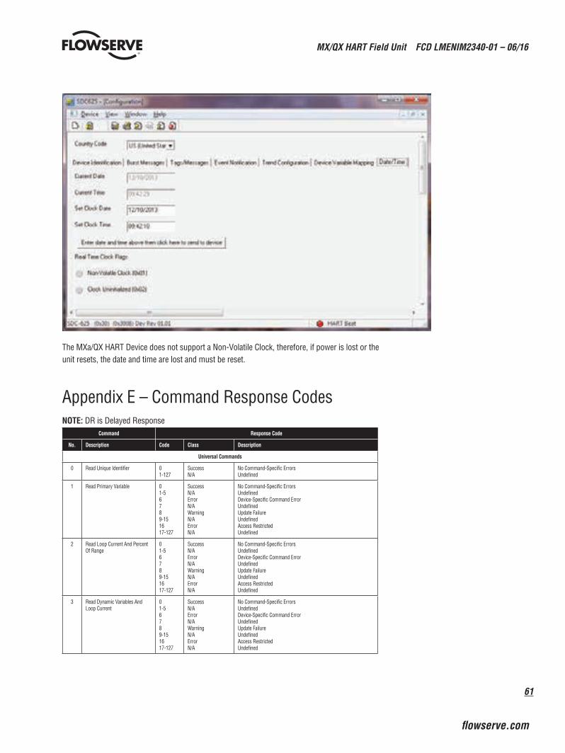
61
MX/QX HART Field Unit FCD LMENIM2340-01 – 06/16
flowserve.com
The MXa/QX HART Device does not support a Non-Volatile Clock, therefore, if power is lost or the unit resets, the date and time are lost and must be reset.
Appendix E – Command Response CodesNOTE: DR is Delayed Response
Command Response Code
No. Description Code Class Description
Universal Commands
0 Read Unique Identifier 01-127
SuccessN/A
No Command-Specific ErrorsUndefined
1 Read Primary Variable 01-56789-151617-127
SuccessN/AErrorN/AWarningN/AErrorN/A
No Command-Specific ErrorsUndefinedDevice-Specific Command ErrorUndefinedUpdate FailureUndefinedAccess RestrictedUndefined
2 Read Loop Current And Percent Of Range
01-56789-151617-127
SuccessN/AErrorN/AWarningN/AErrorN/A
No Command-Specific ErrorsUndefinedDevice-Specific Command ErrorUndefinedUpdate FailureUndefinedAccess RestrictedUndefined
3 Read Dynamic Variables And Loop Current
01-56789-151617-127
SuccessN/AErrorN/AWarningN/AErrorN/A
No Command-Specific ErrorsUndefinedDevice-Specific Command ErrorUndefinedUpdate FailureUndefinedAccess RestrictedUndefined
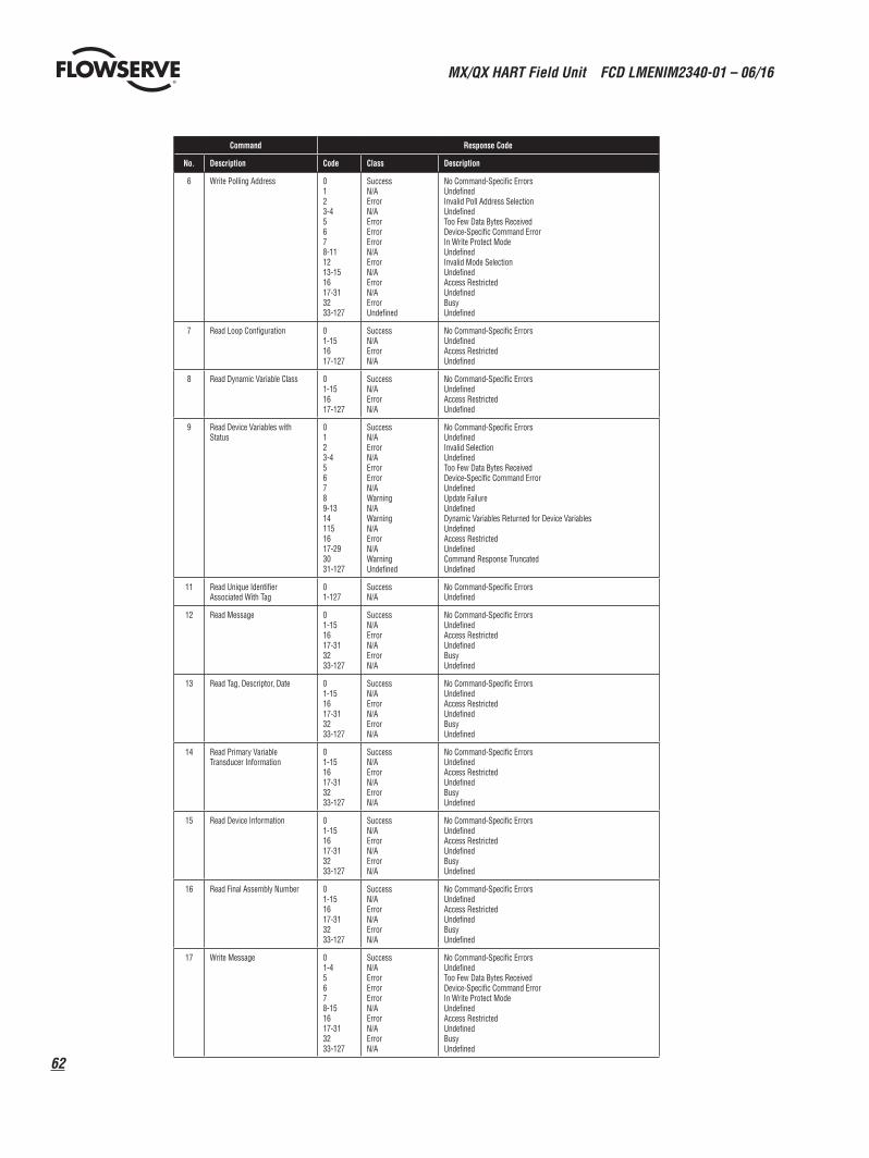
MX/QX HART Field Unit FCD LMENIM2340-01 – 06/16
62
Command Response Code
No. Description Code Class Description
6 Write Polling Address 0123-45678-111213-151617-313233-127
SuccessN/AErrorN/AErrorErrorErrorN/AErrorN/AErrorN/AErrorUndefined
No Command-Specific ErrorsUndefinedInvalid Poll Address SelectionUndefinedToo Few Data Bytes ReceivedDevice-Specific Command ErrorIn Write Protect ModeUndefinedInvalid Mode SelectionUndefinedAccess RestrictedUndefinedBusyUndefined
7 Read Loop Configuration 01-151617-127
SuccessN/AErrorN/A
No Command-Specific ErrorsUndefinedAccess RestrictedUndefined
8 Read Dynamic Variable Class 01-151617-127
SuccessN/AErrorN/A
No Command-Specific ErrorsUndefinedAccess RestrictedUndefined
9 Read Device Variables with Status
0123-456789-13141151617-293031-127
SuccessN/AErrorN/AErrorErrorN/AWarningN/AWarningN/AErrorN/AWarningUndefined
No Command-Specific ErrorsUndefinedInvalid SelectionUndefinedToo Few Data Bytes ReceivedDevice-Specific Command ErrorUndefinedUpdate FailureUndefinedDynamic Variables Returned for Device VariablesUndefinedAccess RestrictedUndefinedCommand Response TruncatedUndefined
11 Read Unique Identifier Associated With Tag
01-127
SuccessN/A
No Command-Specific ErrorsUndefined
12 Read Message 01-151617-313233-127
SuccessN/AErrorN/AErrorN/A
No Command-Specific ErrorsUndefinedAccess RestrictedUndefinedBusyUndefined
13 Read Tag, Descriptor, Date 01-151617-313233-127
SuccessN/AErrorN/AErrorN/A
No Command-Specific ErrorsUndefinedAccess RestrictedUndefinedBusyUndefined
14 Read Primary Variable Transducer Information
01-151617-313233-127
SuccessN/AErrorN/AErrorN/A
No Command-Specific ErrorsUndefinedAccess RestrictedUndefinedBusyUndefined
15 Read Device Information 01-151617-313233-127
SuccessN/AErrorN/AErrorN/A
No Command-Specific ErrorsUndefinedAccess RestrictedUndefinedBusyUndefined
16 Read Final Assembly Number 01-151617-313233-127
SuccessN/AErrorN/AErrorN/A
No Command-Specific ErrorsUndefinedAccess RestrictedUndefinedBusyUndefined
17 Write Message 01-45678-151617-313233-127
SuccessN/AErrorErrorErrorN/AErrorN/AErrorN/A
No Command-Specific ErrorsUndefinedToo Few Data Bytes ReceivedDevice-Specific Command ErrorIn Write Protect ModeUndefinedAccess RestrictedUndefinedBusyUndefined
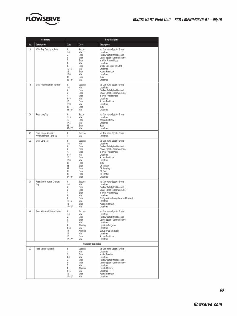
63
MX/QX HART Field Unit FCD LMENIM2340-01 – 06/16
flowserve.com
Command Response Code
No. Description Code Class Description
18 Write Tag, Descriptor, Date 01-45678910-151617-313233-127
SuccessN/AErrorErrorErrorN/AErrorN/AErrorN/AErrorN/A
No Command-Specific ErrorsUndefinedToo Few Data Bytes ReceivedDevice-Specific Command ErrorIn Write Protect ModeUndefinedInvalid Date Code DetectedUndefinedAccess RestrictedUndefinedBusyUndefined
19 Write Final Assembly Number 01-45678-151617-313233-127
SuccessN/AErrorErrorErrorN/AErrorN/AErrorN/A
No Command-Specific ErrorsUndefinedToo Few Data Bytes ReceivedDevice-Specific Command ErrorIn Write Protect ModeUndefinedAccess RestrictedUndefinedBusyUndefined
20 Read Long Tag 01-151617-313233-127
SuccessN/AErrorN/AErrorN/A
No Command-Specific ErrorsUndefinedAccess RestrictedUndefinedBusyUndefined
21 Read Unique Identifier Associated With Long Tag
01
SuccessN/A
No Command-Specific ErrorsUndefined
22 Write Long Tag 01-45678-151617-31323334353637-127
SuccessN/AErrorErrorErrorN/AErrorN/AErrorErrorErrorErrorErrorError
No Command-Specific ErrorsUndefinedToo Few Data Bytes ReceivedDevice-Specific Command ErrorIn Write Protect ModeUndefinedAccess RestrictedUndefinedBusyDR InitiatedDR RunningDR DeadDR ConflictUndefined
38 Reset Configuration Changed Flag
01-45678910-151617-127
SuccessN/AErrorErrorErrorN/AErrorN/AErrorN/A
No Command-Specific ErrorsUndefinedToo Few Data Bytes ReceivedDevice-Specific Command ErrorIn Write Protect ModeUndefinedConfiguration Change Counter MismatchUndefinedAccess RestrictedUndefined
48 Read Additional Device Status 01-456789-1314151617-127
SuccessN/AErrorErrorN/AWarningN/AWarningN/AErrorN/A
No Command-Specific ErrorsUndefinedToo Few Data Bytes ReceivedDevice-Specific Command ErrorUndefinedUpdate in ProgressUndefinedStatus Bytes MismatchUndefinedAccess RestrictedUndefined
Common Commands
33 Read Device Variables 0123-456789-151617-127
SuccessN/AErrorN/AErrorErrorN/AWarningN/AErrorN/A
No Command-Specific ErrorsUndefinedInvalid SelectionUndefinedToo Few Data Bytes ReceivedDevice-Specific Command ErrorUndefinedUpdated FailureUndefinedAccess RestrictedUndefined
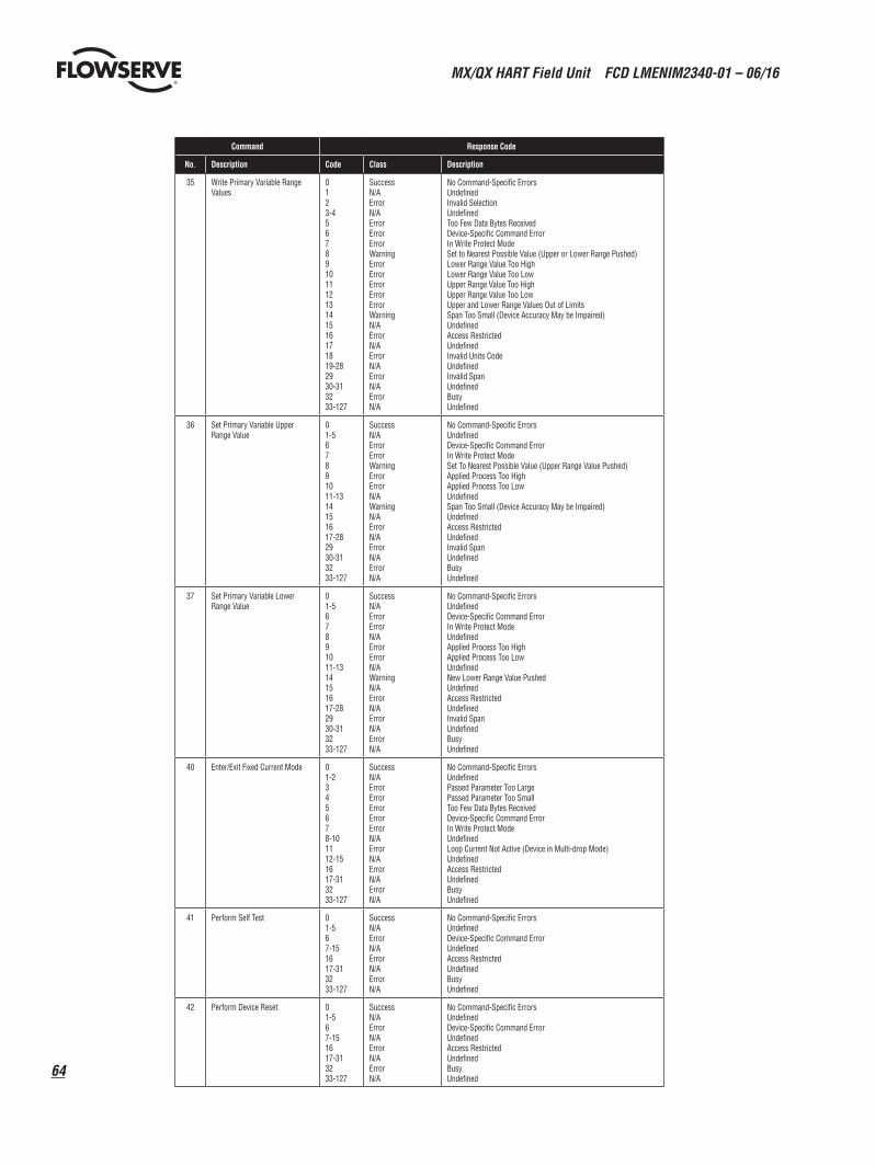
MX/QX HART Field Unit FCD LMENIM2340-01 – 06/16
64
Command Response Code
No. Description Code Class Description
35 Write Primary Variable Range Values
0123-45678910111213141516171819-282930-313233-127
SuccessN/AErrorN/AErrorErrorErrorWarningErrorErrorErrorErrorErrorWarningN/AErrorN/AErrorN/AErrorN/AErrorN/A
No Command-Specific ErrorsUndefinedInvalid SelectionUndefinedToo Few Data Bytes ReceivedDevice-Specific Command ErrorIn Write Protect ModeSet to Nearest Possible Value (Upper or Lower Range Pushed)Lower Range Value Too HighLower Range Value Too LowUpper Range Value Too HighUpper Range Value Too LowUpper and Lower Range Values Out of LimitsSpan Too Small (Device Accuracy May be Impaired)UndefinedAccess RestrictedUndefinedInvalid Units CodeUndefinedInvalid SpanUndefinedBusyUndefined
36 Set Primary Variable Upper Range Value
01-567891011-1314151617-282930-313233-127
SuccessN/AErrorErrorWarningErrorErrorN/AWarningN/AErrorN/AErrorN/AErrorN/A
No Command-Specific ErrorsUndefinedDevice-Specific Command ErrorIn Write Protect ModeSet To Nearest Possible Value (Upper Range Value Pushed)Applied Process Too HighApplied Process Too LowUndefinedSpan Too Small (Device Accuracy May be Impaired)UndefinedAccess RestrictedUndefinedInvalid SpanUndefinedBusyUndefined
37 Set Primary Variable Lower Range Value
01-567891011-1314151617-282930-313233-127
SuccessN/AErrorErrorN/AErrorErrorN/AWarningN/AErrorN/AErrorN/AErrorN/A
No Command-Specific ErrorsUndefinedDevice-Specific Command ErrorIn Write Protect ModeUndefinedApplied Process Too HighApplied Process Too LowUndefinedNew Lower Range Value PushedUndefinedAccess RestrictedUndefinedInvalid SpanUndefinedBusyUndefined
40 Enter/Exit Fixed Current Mode 01-2345678-101112-151617-313233-127
SuccessN/AErrorErrorErrorErrorErrorN/AErrorN/AErrorN/AErrorN/A
No Command-Specific ErrorsUndefinedPassed Parameter Too LargePassed Parameter Too SmallToo Few Data Bytes ReceivedDevice-Specific Command ErrorIn Write Protect ModeUndefinedLoop Current Not Active (Device in Multi-drop Mode)UndefinedAccess RestrictedUndefinedBusyUndefined
41 Perform Self Test 01-567-151617-313233-127
SuccessN/AErrorN/AErrorN/AErrorN/A
No Command-Specific ErrorsUndefinedDevice-Specific Command ErrorUndefinedAccess RestrictedUndefinedBusyUndefined
42 Perform Device Reset 01-567-151617-313233-127
SuccessN/AErrorN/AErrorN/AErrorN/A
No Command-Specific ErrorsUndefinedDevice-Specific Command ErrorUndefinedAccess RestrictedUndefinedBusyUndefined
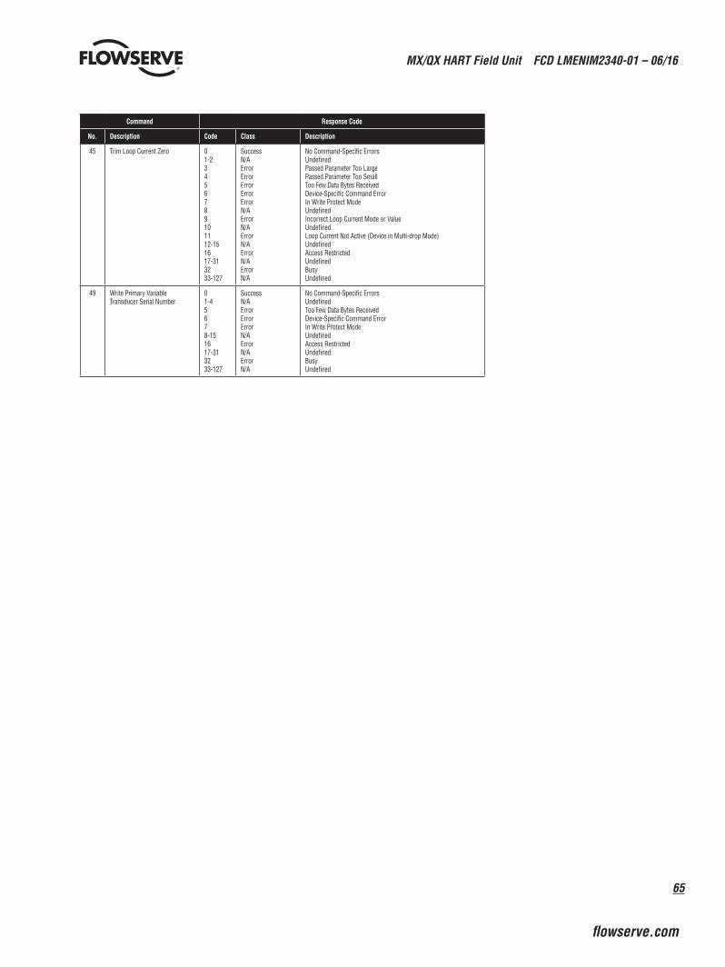
65
MX/QX HART Field Unit FCD LMENIM2340-01 – 06/16
flowserve.com
Command Response Code
No. Description Code Class Description
45 Trim Loop Current Zero 01-23456789101112-151617-313233-127
SuccessN/AErrorErrorErrorErrorErrorN/AErrorN/AErrorN/AErrorN/AErrorN/A
No Command-Specific ErrorsUndefinedPassed Parameter Too LargePassed Parameter Too SmallToo Few Data Bytes ReceivedDevice-Specific Command ErrorIn Write Protect ModeUndefinedIncorrect Loop Current Mode or ValueUndefinedLoop Current Not Active (Device in Multi-drop Mode)UndefinedAccess RestrictedUndefinedBusyUndefined
49 Write Primary Variable Transducer Serial Number
01-45678-151617-313233-127
SuccessN/AErrorErrorErrorN/AErrorN/AErrorN/A
No Command-Specific ErrorsUndefinedToo Few Data Bytes ReceivedDevice-Specific Command ErrorIn Write Protect ModeUndefinedAccess RestrictedUndefinedBusyUndefined
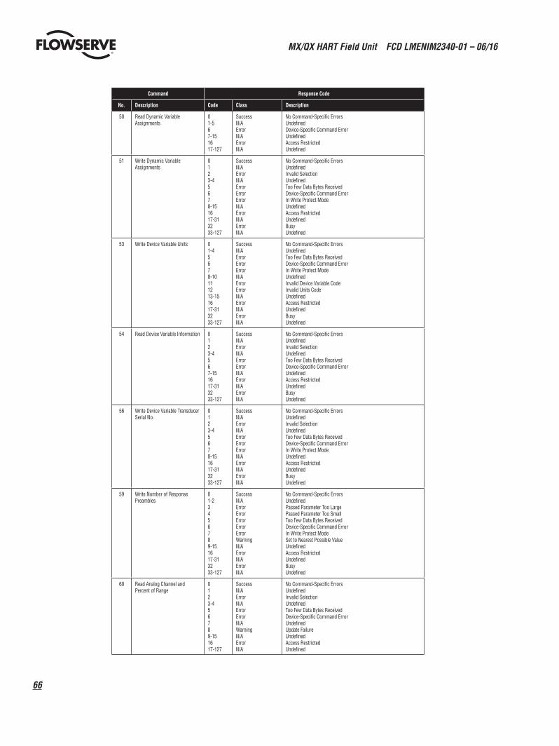
MX/QX HART Field Unit FCD LMENIM2340-01 – 06/16
66
Command Response Code
No. Description Code Class Description
50 Read Dynamic Variable Assignments
01-567-151617-127
SuccessN/AErrorN/AErrorN/A
No Command-Specific ErrorsUndefinedDevice-Specific Command ErrorUndefinedAccess RestrictedUndefined
51 Write Dynamic Variable Assignments
0123-45678-151617-313233-127
SuccessN/AErrorN/AErrorErrorErrorN/AErrorN/AErrorN/A
No Command-Specific ErrorsUndefinedInvalid SelectionUndefinedToo Few Data Bytes ReceivedDevice-Specific Command ErrorIn Write Protect ModeUndefinedAccess RestrictedUndefinedBusyUndefined
53 Write Device Variable Units 01-45678-10111213-151617-313233-127
SuccessN/AErrorErrorErrorN/AErrorErrorN/AErrorN/AErrorN/A
No Command-Specific ErrorsUndefinedToo Few Data Bytes ReceivedDevice-Specific Command ErrorIn Write Protect ModeUndefinedInvalid Device Variable CodeInvalid Units CodeUndefinedAccess RestrictedUndefinedBusyUndefined
54 Read Device Variable Information 0123-4567-151617-313233-127
SuccessN/AErrorN/AErrorErrorN/AErrorN/AErrorN/A
No Command-Specific ErrorsUndefinedInvalid SelectionUndefinedToo Few Data Bytes ReceivedDevice-Specific Command ErrorUndefinedAccess RestrictedUndefinedBusyUndefined
56 Write Device Variable Transducer Serial No.
0123-45678-151617-313233-127
SuccessN/AErrorN/AErrorErrorErrorN/AErrorN/AErrorN/A
No Command-Specific ErrorsUndefinedInvalid SelectionUndefinedToo Few Data Bytes ReceivedDevice-Specific Command ErrorIn Write Protect ModeUndefinedAccess RestrictedUndefinedBusyUndefined
59 Write Number of Response Preambles
01-23456789-151617-313233-127
SuccessN/AErrorErrorErrorErrorErrorWarningN/AErrorN/AErrorN/A
No Command-Specific ErrorsUndefinedPassed Parameter Too LargePassed Parameter Too SmallToo Few Data Bytes ReceivedDevice-Specific Command ErrorIn Write Protect ModeSet to Nearest Possible ValueUndefinedAccess RestrictedUndefinedBusyUndefined
60 Read Analog Channel and Percent of Range
0123-456789-151617-127
SuccessN/AErrorN/AErrorErrorN/AWarningN/AErrorN/A
No Command-Specific ErrorsUndefinedInvalid SelectionUndefinedToo Few Data Bytes ReceivedDevice-Specific Command ErrorUndefinedUpdate FailureUndefinedAccess RestrictedUndefined
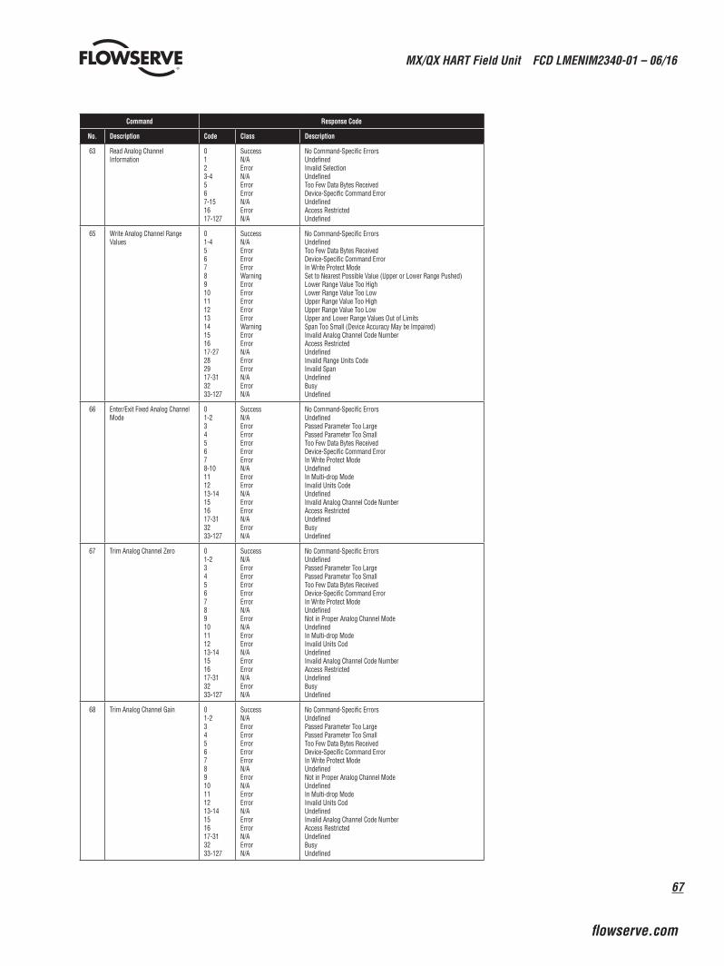
67
MX/QX HART Field Unit FCD LMENIM2340-01 – 06/16
flowserve.com
Command Response Code
No. Description Code Class Description
63 Read Analog Channel Information
0123-4567-151617-127
SuccessN/AErrorN/AErrorErrorN/AErrorN/A
No Command-Specific ErrorsUndefinedInvalid SelectionUndefinedToo Few Data Bytes ReceivedDevice-Specific Command ErrorUndefinedAccess RestrictedUndefined
65 Write Analog Channel Range Values
01-4567891011121314151617-27282917-313233-127
SuccessN/AErrorErrorErrorWarningErrorErrorErrorErrorErrorWarningErrorErrorN/AErrorErrorN/AErrorN/A
No Command-Specific ErrorsUndefinedToo Few Data Bytes ReceivedDevice-Specific Command ErrorIn Write Protect ModeSet to Nearest Possible Value (Upper or Lower Range Pushed)Lower Range Value Too HighLower Range Value Too LowUpper Range Value Too HighUpper Range Value Too LowUpper and Lower Range Values Out of LimitsSpan Too Small (Device Accuracy May be Impaired)Invalid Analog Channel Code NumberAccess RestrictedUndefinedInvalid Range Units CodeInvalid SpanUndefinedBusyUndefined
66 Enter/Exit Fixed Analog Channel Mode
01-2345678-10111213-14151617-313233-127
SuccessN/AErrorErrorErrorErrorErrorN/AErrorErrorN/AErrorErrorN/AErrorN/A
No Command-Specific ErrorsUndefinedPassed Parameter Too LargePassed Parameter Too SmallToo Few Data Bytes ReceivedDevice-Specific Command ErrorIn Write Protect ModeUndefinedIn Multi-drop ModeInvalid Units CodeUndefinedInvalid Analog Channel Code NumberAccess RestrictedUndefinedBusyUndefined
67 Trim Analog Channel Zero 01-2345678910111213-14151617-313233-127
SuccessN/AErrorErrorErrorErrorErrorN/AErrorN/AErrorErrorN/AErrorErrorN/AErrorN/A
No Command-Specific ErrorsUndefinedPassed Parameter Too LargePassed Parameter Too SmallToo Few Data Bytes ReceivedDevice-Specific Command ErrorIn Write Protect ModeUndefinedNot in Proper Analog Channel ModeUndefinedIn Multi-drop ModeInvalid Units CodUndefinedInvalid Analog Channel Code NumberAccess RestrictedUndefinedBusyUndefined
68 Trim Analog Channel Gain 01-2345678910111213-14151617-313233-127
SuccessN/AErrorErrorErrorErrorErrorN/AErrorN/AErrorErrorN/AErrorErrorN/AErrorN/A
No Command-Specific ErrorsUndefinedPassed Parameter Too LargePassed Parameter Too SmallToo Few Data Bytes ReceivedDevice-Specific Command ErrorIn Write Protect ModeUndefinedNot in Proper Analog Channel ModeUndefinedIn Multi-drop ModeInvalid Units CodUndefinedInvalid Analog Channel Code NumberAccess RestrictedUndefinedBusyUndefined
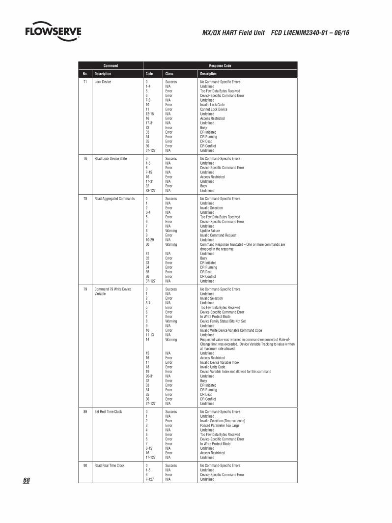
MX/QX HART Field Unit FCD LMENIM2340-01 – 06/16
68
Command Response Code
No. Description Code Class Description
71 Lock Device 01-4567-9101112-151617-31323334353637-127
SuccessN/AErrorErrorN/AErrorErrorN/AErrorN/AErrorErrorErrorErrorErrorN/A
No Command-Specific ErrorsUndefinedToo Few Data Bytes ReceivedDevice-Specific Command ErrorUndefinedInvalid Lock CodeCannot Lock DeviceUndefinedAccess RestrictedUndefinedBusyDR InitiatedDR RunningDR DeadDR ConflictUndefined
76 Read Lock Device State 01-567-151617-313233-127
SuccessN/AErrorN/AErrorN/AErrorN/A
No Command-Specific ErrorsUndefinedDevice-Specific Command ErrorUndefinedAccess RestrictedUndefinedBusyUndefined
78 Read Aggregated Commands 0123-45678910-2930
31323334353637-127
SuccessN/AErrorN/AErrorErrorN/AWarningErrorN/AWarning
N/AErrorErrorErrorErrorErrorN/A
No Command-Specific ErrorsUndefinedInvalid SelectionUndefinedToo Few Data Bytes ReceivedDevice-Specific Command ErrorUndefinedUpdate FailureInvalid Command RequestUndefinedCommand Response Truncated – One or more commands are dropped in the responseUndefinedBusyDR InitiatedDR RunningDR DeadDR ConflictUndefined
79 Command 79 Write Device Variable
0123-4567891011-1314
151617181920-31323334353637-127
SuccessN/AErrorN/AErrorErrorErrorWarningN/AErrorN/AWarning
N/AErrorErrorErrorErrorN/AErrorErrorErrorErrorErrorN/A
No Command-Specific ErrorsUndefinedInvalid SelectionUndefinedToo Few Data Bytes ReceivedDevice-Specific Command ErrorIn Write Protect ModeDevice Family Status Bits Not SetUndefinedInvalid Write Device Variable Command CodeUndefinedRequested value was returned in command response but Rate-of-Change limit was exceeded. Device Variable Tracking to value written at maximum rate allowed.UndefinedAccess RestrictedInvalid Device Variable IndexInvalid Units CodeDevice Variable Index not allowed for this commandUndefinedBusyDR InitiatedDR RunningDR DeadDR ConflictUndefined
89 Set Real Time Clock 012345678-151617-127
SuccessN/AErrorErrorN/AErrorErrorErrorN/AErrorN/A
No Command-Specific ErrorsUndefinedInvalid Selection (Time-set code)Passed Parameter Too LargeUndefinedToo Few Data Bytes ReceivedDevice-Specific Command ErrorIn Write Protect ModeUndefinedAccess RestrictedUndefined
90 Read Real Time Clock 01-567-127
SuccessN/AErrorN/A
No Command-Specific ErrorsUndefinedDevice-Specific Command ErrorUndefined

69
MX/QX HART Field Unit FCD LMENIM2340-01 – 06/16
flowserve.com
Command Response Code
No. Description Code Class Description
91 Read Trend Configuration 01-4567-101112-127
SuccessN/AErrorErrorN/AErrorN/A
No Command-Specific ErrorsUndefinedToo Few Data Bytes ReceivedDevice-Specific Command ErrorUndefinedInvalid Trend NumberUndefined
92 Write Trend Configuration 0123456789-101112-15161718-127
SuccessN/AErrorErrorErrorErrorErrorErrorWarningN/AErrorN/AErrorErrorN/A
No Command-Specific ErrorsUndefinedInvalid SelectionPassed Parameter Too Large (trend update period)Passed Parameter Too Small (trend update period)Too Few Data Bytes ReceivedDevice-Specific Command ErrorIn Write Protect ModeSet to Nearest Possible Value (trend update period)UndefinedInvalid Trend NumberUndefinedAccess RestrictedInvalid Device Variable IndexUndefined
93 Read Trend 01-456789-101112-127
SuccessN/AErrorErrorN/AWarningN/AErrorN/A
No Command-Specific ErrorsUndefinedToo Few Data Bytes ReceivedDevice-Specific Command ErrorUndefinedTrend not ActiveUndefinedInvalid Trend NumberUndefined
95 Read Device Communications Statistics
01-567-127
SuccessN/AErrorN/A
No Command-Specific ErrorsUndefinedDevice-Specific Command ErrorUndefined
103 Write Burst Period 01-45678910-151617-31323334353637-127
SuccessN/AErrorErrorErrorWarningErrorN/AErrorN/AErrorErrorErrorErrorErrorN/A
No Command-Specific ErrorsUndefinedToo Few Data Bytes ReceivedDevice-Specific Command ErrorIn Write Protect ModeUpdate Times AdjustedInvalid Burst MessageUndefinedAccess RestrictedUndefinedBusyDR InitiatedDR RunningDR DeadDR ConflictUndefined
104 Write Burst Trigger 01-234567891011121314-151617-31323334353637-127
SuccessN/AErrorErrorErrorErrorErrorWarningErrorN/AErrorErrorErrorN/AErrorN/AErrorErrorErrorErrorErrorN/A
No Command-Specific ErrorsUndefinedPassed Parameter Too LargePassed Parameter Too SmallToo Few Data Bytes ReceivedDevice-Specific Command ErrorIn Write Protect ModeBurst Condition ConflictInvalid Burst MessageUndefinedInvalid Device Variable ClassificationInvalid Units CodeInvalid Burst Trigger Mode SelectionUndefinedAccess RestrictedUndefinedBusyDR InitiatedDR RunningDR DeadDR ConflictUndefined
105 Read Burst Mode Configuration 01-567-8910-313233-127
SuccessN/AErrorN/A ErrorN/AErrorN/A
No Command-Specific ErrorsUndefinedDevice-Specific Command ErrorUndefinedInvalid Burst MessageUndefinedBusyUndefined
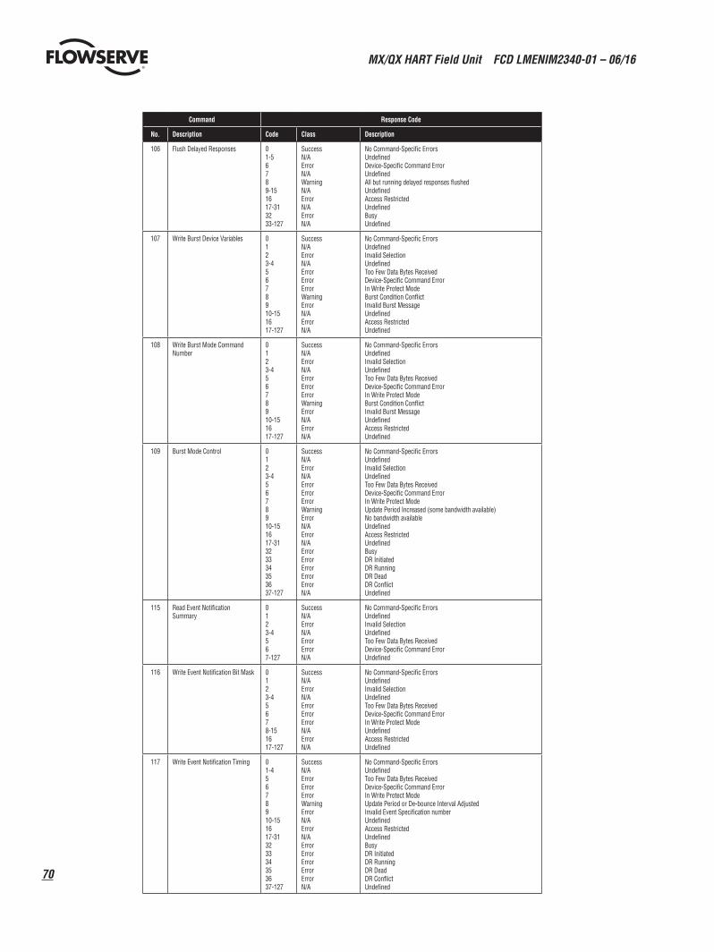
MX/QX HART Field Unit FCD LMENIM2340-01 – 06/16
70
Command Response Code
No. Description Code Class Description
106 Flush Delayed Responses 01-56789-151617-313233-127
SuccessN/AErrorN/AWarningN/AErrorN/AErrorN/A
No Command-Specific ErrorsUndefinedDevice-Specific Command ErrorUndefinedAll but running delayed responses flushedUndefinedAccess RestrictedUndefinedBusyUndefined
107 Write Burst Device Variables 0123-45678910-151617-127
SuccessN/AErrorN/AErrorErrorErrorWarningErrorN/AErrorN/A
No Command-Specific ErrorsUndefinedInvalid SelectionUndefinedToo Few Data Bytes ReceivedDevice-Specific Command ErrorIn Write Protect ModeBurst Condition ConflictInvalid Burst MessageUndefinedAccess RestrictedUndefined
108 Write Burst Mode Command Number
0123-45678910-151617-127
SuccessN/AErrorN/AErrorErrorErrorWarningErrorN/AErrorN/A
No Command-Specific ErrorsUndefinedInvalid SelectionUndefinedToo Few Data Bytes ReceivedDevice-Specific Command ErrorIn Write Protect ModeBurst Condition ConflictInvalid Burst MessageUndefinedAccess RestrictedUndefined
109 Burst Mode Control 0123-45678910-151617-31323334353637-127
SuccessN/AErrorN/AErrorErrorErrorWarningErrorN/AErrorN/AErrorErrorErrorErrorErrorN/A
No Command-Specific ErrorsUndefinedInvalid SelectionUndefinedToo Few Data Bytes ReceivedDevice-Specific Command ErrorIn Write Protect ModeUpdate Period Increased (some bandwidth available)No bandwidth availableUndefinedAccess RestrictedUndefinedBusyDR InitiatedDR RunningDR DeadDR ConflictUndefined
115 Read Event Notification Summary
0123-4567-127
SuccessN/AErrorN/AErrorErrorN/A
No Command-Specific ErrorsUndefinedInvalid SelectionUndefinedToo Few Data Bytes ReceivedDevice-Specific Command ErrorUndefined
116 Write Event Notification Bit Mask 0123-45678-151617-127
SuccessN/AErrorN/AErrorErrorErrorN/AErrorN/A
No Command-Specific ErrorsUndefinedInvalid SelectionUndefinedToo Few Data Bytes ReceivedDevice-Specific Command ErrorIn Write Protect ModeUndefinedAccess RestrictedUndefined
117 Write Event Notification Timing 01-45678910-151617-31323334353637-127
SuccessN/AErrorErrorErrorWarningErrorN/AErrorN/AErrorErrorErrorErrorErrorN/A
No Command-Specific ErrorsUndefinedToo Few Data Bytes ReceivedDevice-Specific Command ErrorIn Write Protect ModeUpdate Period or De-bounce Interval AdjustedInvalid Event Specification numberUndefinedAccess RestrictedUndefinedBusyDR InitiatedDR RunningDR DeadDR ConflictUndefined
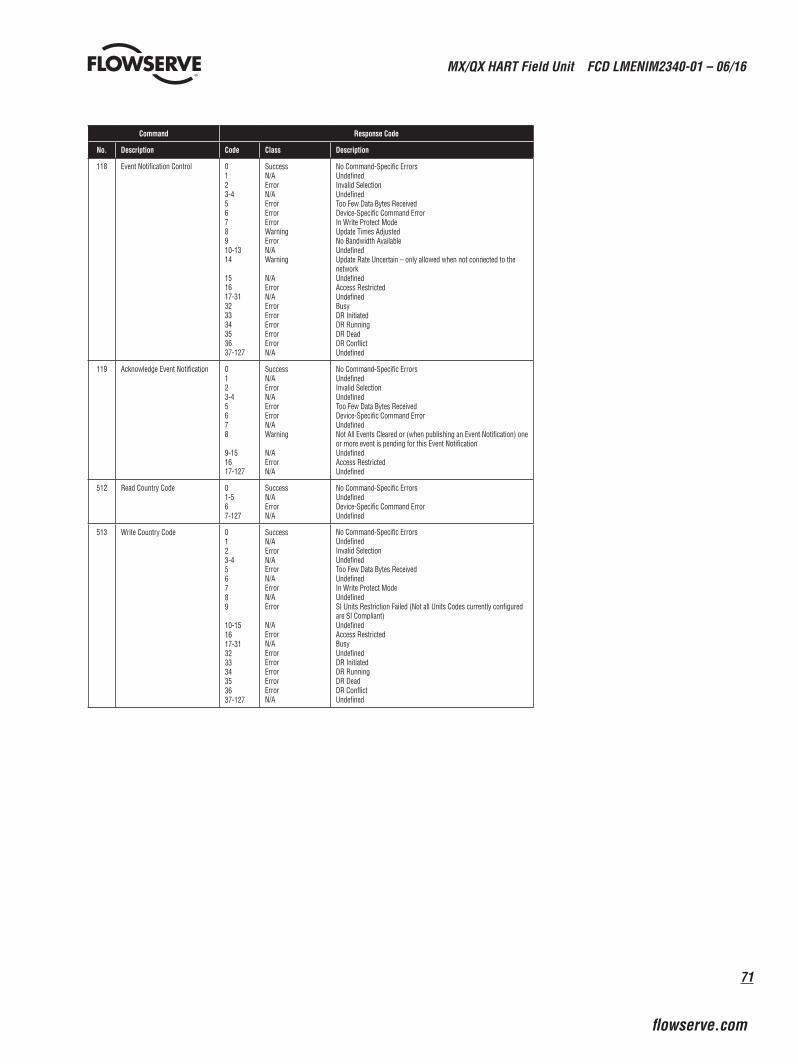
71
MX/QX HART Field Unit FCD LMENIM2340-01 – 06/16
flowserve.com
Command Response Code
No. Description Code Class Description
118 Event Notification Control 0123-45678910-1314
151617-31323334353637-127
SuccessN/AErrorN/AErrorErrorErrorWarningErrorN/AWarning
N/AErrorN/AErrorErrorErrorErrorErrorN/A
No Command-Specific ErrorsUndefinedInvalid SelectionUndefinedToo Few Data Bytes ReceivedDevice-Specific Command ErrorIn Write Protect ModeUpdate Times AdjustedNo Bandwidth AvailableUndefinedUpdate Rate Uncertain – only allowed when not connected to the networkUndefinedAccess RestrictedUndefinedBusyDR InitiatedDR RunningDR DeadDR ConflictUndefined
119 Acknowledge Event Notification 0123-45678
9-151617-127
SuccessN/AErrorN/AErrorErrorN/AWarning
N/AErrorN/A
No Command-Specific ErrorsUndefinedInvalid SelectionUndefinedToo Few Data Bytes ReceivedDevice-Specific Command ErrorUndefinedNot All Events Cleared or (when publishing an Event Notification) one or more event is pending for this Event NotificationUndefinedAccess RestrictedUndefined
512 Read Country Code 01-567-127
SuccessN/AErrorN/A
No Command-Specific ErrorsUndefinedDevice-Specific Command ErrorUndefined
513 Write Country Code 0123-456789
10-151617-31323334353637-127
SuccessN/AErrorN/A ErrorN/AErrorN/AError
N/AErrorN/AErrorErrorErrorErrorErrorN/A
No Command-Specific ErrorsUndefinedInvalid SelectionUndefinedToo Few Data Bytes ReceivedUndefinedIn Write Protect ModeUndefinedSI Units Restriction Failed (Not all Units Codes currently configured are SI Compliant)UndefinedAccess RestrictedBusyUndefinedDR InitiatedDR RunningDR DeadDR ConflictUndefined
To find your local Flowserve representative, visit www.flowserve.com, www.limitorque.com or call USA 1 800 225 6989.
flowserve.com
Flowserve Corporation has established industry leadership in the design and manufacture of its products. When properly selected, this Flowserve product is designed to perform its intended function safely during its useful life. However, the purchaser or user of Flowserve products should be aware that Flowserve products might be used in numerous applications under a wide variety of industrial service conditions. Although Flowserve can (and often does) provide general guidelines, it cannot provide specific data and warnings for all possible applications. The purchaser/user must therefore assume the ultimate responsibility for the proper sizing and selection, installation, operation, and maintenance of Flowserve products. The purchaser/user should read and understand the Installation Operation Maintenance (IOM) instructions included with the product, and train its employees and contractors in the safe use of Flowserve products in connection with the specific application.While the information and specifications contained in this literature are believed to be accurate, they are supplied for informative purposes only and should not be considered certified or as a guarantee of satisfactory results by reliance thereon. Nothing contained herein is to be construed as a warranty or guarantee, express or implied, regarding any matter with respect to this product. Because Flowserve is continually improving and upgrading its product design, the specifications, dimensions and information contained herein are subject to change without notice. Should any question arise concerning these provisions, the purchaser/user should contact Flowserve Corporation at any one of its worldwide operations or offices.© 2013 Flowserve Corporation, Irving, Texas, USA. Flowserve is a registered trademark of Flowserve Corporation.
FCD LMENIM2340-01 (E) 06/16 © 2014 Flowserve Corporation.
Flowserve CorporationFlow Control
United StatesFlowserve Limitorque5114 Woodall Road P.O. Box 11318Lynchburg, VA 24506-1318Phone: 434-528-4400Fax: 434-845-9736
EnglandFlowserve LimitorqueEuro HouseAbex RoadNewburyBerkshire, RG14 5EYUnited KingdomPhone: 44-1-635-46999Fax: 44-1-635-36034
JapanLimitorque – Nippon Gear Co., Ltd.Asahi-Seimei Bldg. 4th Floor1-11-11 Kita-Saiwai, Nishi-KuYokohama-Shi, (220-0004)JapanPhone: 81-45-326-2065Fax: 81-45-320-5962
CanadaFlowserve Limitorque120 Vinyl CourtWoodbridge, Ontario L4L 4A3CanadaPhone: 905-856-4565Fax: 905-856-7905
SingaporeLimitorque Asia, Pte., Ltd.12, Tuas Avenue 20Singapore 638824Phone: 65-6868-4628Fax: 65-6862-4940
ChinaLimitorque Beijing, Pte., Ltd.RM A1/A222/F, East Area, Hanwei PlazaNo. 7 Guanghua Road, Chaoyang DistrictBeijing 100004, Peoples Republic of ChinaPhone: 86-10-5921-0606Fax: 86-10-6561-2702
IndiaFlowserve LimitorqueNo. 10-12, THE OVAL, Third floorVenkatnarayana RoadT. Nagar, Chennai 600 017Phone: 91-44-2432-8755and 91-44-2432-4801Fax: 91-44-2432-8754