user guide tn-sfp-bc55 and tn-sfp-bc55-i - · pdf fileuser guide . tn-sfp-bc55 and...
TRANSCRIPT
33669 Rev. A http://www.transition.com/ Page 1 of 47
User Guide TN-SFP-BC55 and TN-SFP-BC55-I SFP Transceiver Modules
• 1.25Gbps/125Mbps bi-directional data link • Integrated OTDR (Optical Time-Domain Reflectometer) function • Integrated Reflection Immune Operation – any network type • SFF-8472 Digital Diagnostic Function (DMI) • MSA and RoHS Compliant (all models)
Contents Introduction.................................................................................................................................................... 2 Model Numbers ............................................................................................................................................. 2 Functions ....................................................................................................................................................... 2 Features ........................................................................................................................................................ 2 Benefits ......................................................................................................................................................... 3 TN-SFP-BC55/-I Reflection Immune Operation ............................................................................................ 3 Specifications and Standards........................................................................................................................ 6 Optical Specifications .................................................................................................................................... 8 Site Planning ................................................................................................................................................. 8 Related Manuals ........................................................................................................................................... 8 Applications ................................................................................................................................................... 9 SFP Unpacking ........................................................................................................................................... 12 Clean the Optical Fiber Connections .......................................................................................................... 12
Cleaning Process: Inspect, Clean, Re-inspect, Connect ........................................................................ 13 SFP Installation ........................................................................................................................................... 14
Cautions .................................................................................................................................................. 14 Installing an SFP Module ........................................................................................................................ 14 Fiber Cable Physical Characteristics ...................................................................................................... 15 Connecting Fiber Cables ........................................................................................................................ 15 Removing an SFP Module ...................................................................................................................... 15
Prerequisites and Restrictions .................................................................................................................... 16 OTDR SFP Behavior ................................................................................................................................... 16 Configuration via Web Interface .................................................................................................................. 18 Configuration via CLI ................................................................................................................................... 24 Configuration via SNMP .............................................................................................................................. 34 Sample OTDR Reports ............................................................................................................................... 34 OTDR SFP Feature Cross-Reference ........................................................................................................ 38 Troubleshooting .......................................................................................................................................... 39 For More Information ................................................................................................................................... 43 Record Model and System Information ....................................................................................................... 44 Contact Us................................................................................................................................................... 45 Compliance Information .............................................................................................................................. 45 Record of Revisions .................................................................................................................................... 47
Transition Networks TN-SFP-BC55 and TN-SFP-BC55-I User Guide
33669 Rev. A http://www.transition.com/ Page 2 of 47
Introduction The Transition Networks TN-SFP-BC55 and TN-SFP-BC55-I automatically detect, locate and report Optical Fiber Faults. The ODTR data readout requires additional software support from the switch (Transition Networks S4224) or NID (Transition Networks S3290-xx). The TN-SFP-BC55/-I allows fiber integrity checking and fault-reporting from the service providers, to reduce the Opex (cost per install and cost per repair) for network implementation.
The TN-SFP-BC55-I integrates OTDR functionality into the Transition Networks S4224 CE Switch and S3290-xx NID to provide a cost-effective solution for fiber fault determination, localization, cost reduction, and time-to-repair for customer services.
Model Numbers The two models are typically used in pairs (one of each model), but it is not a requirement. Not all features are supported when not used in pairs of one of each model.
TN-SFP-BC55-I SFP w/OTDR 1000Base-LX/100Base-FX / 1550nm single fiber single mode (LC) / [40km/24.9mi.,] Link Budget: 20.0dB
TN-SFP-BC55 SFP w/ Reflection Immune Operation, 1000Base-LX/100Base-FX, 1550nm single fiber single mode (LC) [40km/24.9mi.,] Link Budget: 20.0dB
The OTDR function can be deployed in two configurations: Both end and Single end, but the use of TN-SFP-BC55-I requires software support from the host device and light pulse is only sent from the TN-SFP-BC55-I. The Both end configuration uses a TN-SFP-BC55-I with a TN-SFP-BC55-I. A Single end configuration uses a TN-SFP-BC55-I with a TN-SFP-BC55. See OTDR SFP Feature Cross-Reference on page 38 to compare and contrast model features.
Functions • Monitors optical fiber links providing fault detection • Uses pulses of light to measure distance to reflection of damaged fiber • Uses standards-based protocols for network monitoring and troubleshooting • Provides Gb Ethernet demarc / end-to-end service assurance / reduced MTTR • Captures, saves, and reports on up to 16 refelctions and up to 10 captures via CLI or Web GUI • Lets you create a "birth certificate" to use as a baseline for measurement
Features • Compliant with IEEE 802.3z, 1000Base-LX, and IEEE802.3 100Base-FX • 55 dB Dynamic Range for the OTDR • Dead Zone of 30 meters or less • Resolution of 10 meters or better • Accuracy of 50 meters or better / Absolute accuracy of +/- 100 meters (at full distance) • Class 1 Laser International Safety Standard IEC 60825 Compliant
Dynamic Range is the max fiber cable length that the longest pulse width can reach in dB. Dead Zone is the length of time the detector is temporary blinded by a high amount of reflected light, until it recovers and can read light again. Resolution is the ability to distinguish between two points on the cable, like intermediate patchcords or closely spaced splices. Accuracy is the correctness of the measurement (the difference between the measured value and the true value of the event being measured).
Note: It is important that every fiber connector be inspected and cleaned prior to mating. See Clean the Optical Fiber Connections on page 12.
Transition Networks TN-SFP-BC55 and TN-SFP-BC55-I User Guide
33669 Rev. A http://www.transition.com/ Page 3 of 47
Benefits • Small Footprint with integrated network monitoring • Single Wavelength Operation in Legacy and UPC connector Networks • Physical layer Fault Detection • Distributed remote fiber monitoring • No additional special equipment
TN-SFP-BC55/-I Reflection Immune Operation Single Fiber Single Wavelength (SFSW) Transceivers transmit and receive at the same wavelength, on single fiber, doubling the optical fiber plant capacity. SFSW transceivers offer many potential benefits to the Network Operator (e.g., seamless CWDM integration, half the fiber, half the CWDM passives, and easier fiber management).
Open connectors, fiber faults and intermittent connections which commonly occur in field deployments, create optical reflections of varying intensities. SFSW transceivers can be susceptible to signals generated by these reflections in the optical fiber cable plant. For example, the reflection from an open non-angle polished (PC or UPC - Blue) optical connector is about 15 dB. The reflected signal may return to the receiver section of the originating transceiver at power levels well within the operating sensitivity range of the receiver. This may cause the originating transceiver to detect this false signal, appearing to the network switch (or any host equipment) as though it was receiving a viable signal. But in fact, an optical loopback condition is created in the network, wreaking havoc with network operations.
Since SFSW transceivers suffer such drawbacks in the presence of optical reflections, their application in real-world conditions has been limited compared to that of their two-wavelength single fiber or two-fiber cousins. Because SFSW transceivers offer so many potential benefits to the Network Operator, a comprehensive solution to the reflection sensitivity problems would provide significant benefits.
Transition Network’s TN-SFP-BC55/-I SFPs with Reflection Immune Operation technology solve the SFSW reflection problems. Transition Network’s TN-SFP-BC55/-I SFP Transceivers now incorporate Reflection Immune Operation. This feature lets our TN-SFP-BC55/-I SFPs recognize reflected signals and avoid ever reporting a link based on a false reflected signal.
Integrated into the TN-SFP-BC55/-I SFP Transceiver hardware and firmware, this operation is totally automatic in operation and is transparent to the host network equipment and optical network (PC and UPC Blue or APC Green optical connector types). Now for the first time, TN-SFP-BC55/-I SFP Transceivers may be substituted anywhere a standard two-fiber SFP Optical Link exists.
With Reflection Immune Operation, all of the benefits of SFSW Links are available, without the reflection-induced drawbacks.While the mechanism of is quite sophisticated, the general approach may be understood by the following simple explanations.
Initial Link Start-Up When first plugged in, or powered up, the TN-SFP-BC55/-I Transceivers on either end of the Link initiate a specific sequence. First, the receiver section becomes active, while the transmitter remains off. The receiver listens for an incoming signal. Since its own transmitter is off, if the receiver detects an inbound signal, and knows that it must be legitimate because it can only be coming from the remote transceiver. Then the local transmitter section becomes active and a link is established between the local and remote transceivers.
The remote transceiver goes through the same sequence. Random timing delays and proprietary algorithms are built into the start-up sequences, to guarantee linking (each transceiver ensures that the incoming signal is from an external source). The extra processing guarantees data link, under any circumstances, between two transceivers, within less than 700 mSec. The overall timing delay in such an event is well within the typical delays inherent in network “handshake” protocols, so all of this remains invisible to network operation and the network users.
Transition Networks TN-SFP-BC55 and TN-SFP-BC55-I User Guide
33669 Rev. A http://www.transition.com/ Page 4 of 47
Interruption of Established Link The case where a Link is functioning correctly but then is interrupted is a bit more complex (for the SFP, not for the network operator or users).
The case of a PC or UPC Blue connector being inadvertently opened somewhere in the span of the Link presents a different scenario since the reflected signal can be similar, or identical, in amplitude to the incoming signal from the other side. The SFP deploys sophisticated digital filtering schemes which allow it to distinguish between the original inbound signal from a remote source, and a signal reflected back to the originating local transceiver. Any interruption of the optical Link will cause brief fluctuation in the optical power levels due to temporary interference patterns in the connector. Fast optical power changes below 0.25 dB are detected and processed by the SFP. Following such a brief disruption, the SFP protocol analyzes the signal origin, and distinguishes between a fluctuation in the link (e.g., due to an intermittent change in a patch panel) and an open link with reflection.
Summary The network operator and network users may enjoy the benefits of SFSW operation without any of the drawbacks associated with legacy systems. This operation resolves self-reflection from an open connector and/or other reflectors. Only remote data is transferred into the host equipment. In designing a network, overall ORL (Optical Return Loss) must be accounted for since it may affect the sensitivity of the data receiver. The user must ensure that the supplier tests and guarantees the link budget within the ORL performance of the operational network.
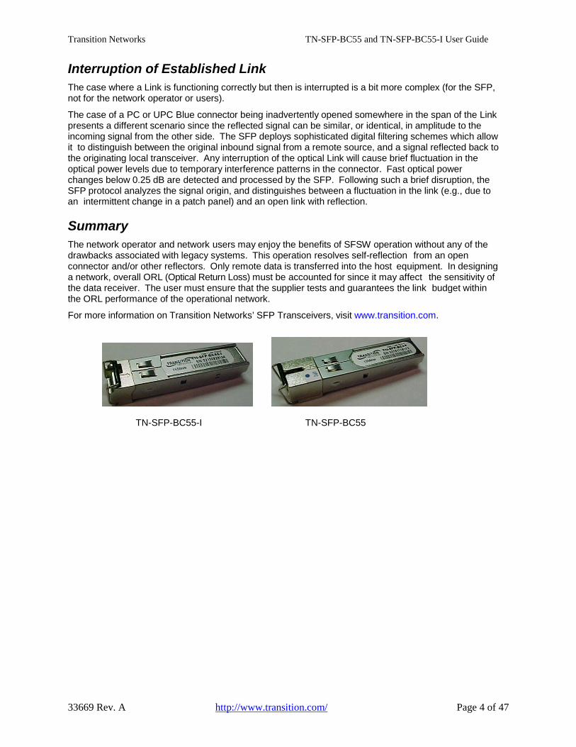
For more information on Transition Networks’ SFP Transceivers, visit www.transition.com.
TN-SFP-BC55-I TN-SFP-BC55
Transition Networks TN-SFP-BC55 and TN-SFP-BC55-I User Guide
33669 Rev. A http://www.transition.com/ Page 5 of 47
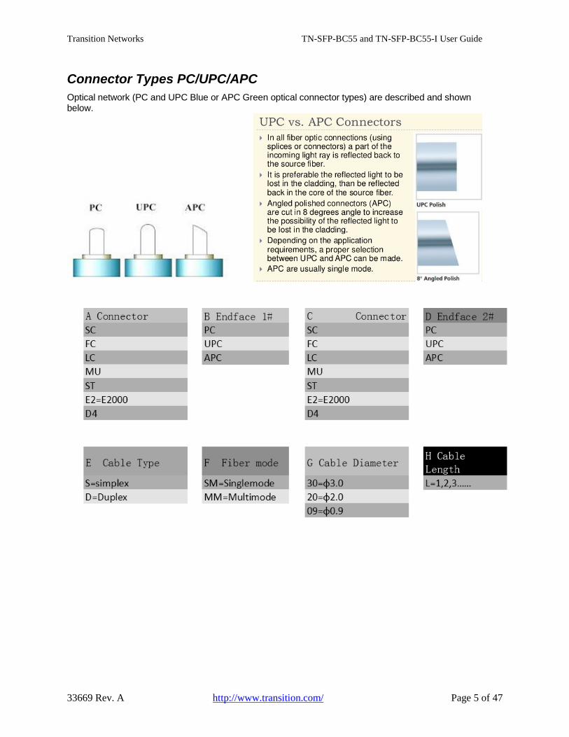
Connector Types PC/UPC/APC Optical network (PC and UPC Blue or APC Green optical connector types) are described and shown below.
Transition Networks TN-SFP-BC55 and TN-SFP-BC55-I User Guide
33669 Rev. A http://www.transition.com/ Page 6 of 47
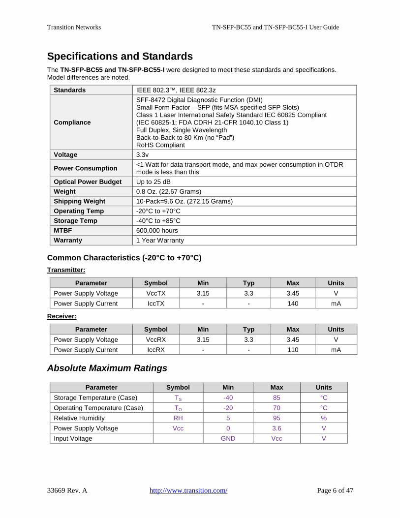
Specifications and Standards The TN-SFP-BC55 and TN-SFP-BC55-I were designed to meet these standards and specifications. Model differences are noted.
Standards IEEE 802.3™, IEEE 802.3z
Compliance
SFF-8472 Digital Diagnostic Function (DMI) Small Form Factor – SFP (fits MSA specified SFP Slots) Class 1 Laser International Safety Standard IEC 60825 Compliant (IEC 60825-1; FDA CDRH 21-CFR 1040.10 Class 1) Full Duplex, Single Wavelength Back-to-Back to 80 Km (no “Pad”) RoHS Compliant
Voltage 3.3v
Power Consumption <1 Watt for data transport mode, and max power consumption in OTDR mode is less than this
Optical Power Budget Up to 25 dB Weight 0.8 Oz. (22.67 Grams) Shipping Weight 10-Pack=9.6 Oz. (272.15 Grams) Operating Temp -20°C to +70°C Storage Temp -40°C to +85°C MTBF 600,000 hours Warranty 1 Year Warranty
Common Characteristics (-20°C to +70°C) Transmitter:
Parameter Symbol Min Typ Max Units Power Supply Voltage VccTX 3.15 3.3 3.45 V Power Supply Current IccTX - - 140 mA
Receiver:
Parameter Symbol Min Typ Max Units Power Supply Voltage VccRX 3.15 3.3 3.45 V Power Supply Current IccRX - - 110 mA
Absolute Maximum Ratings
Parameter Symbol Min Max Units Storage Temperature (Case) TS -40 85 °C Operating Temperature (Case) TO -20 70 °C Relative Humidity RH 5 95 % Power Supply Voltage Vcc 0 3.6 V Input Voltage GND Vcc V

Transition Networks TN-SFP-BC55 and TN-SFP-BC55-I User Guide
33669 Rev. A http://www.transition.com/ Page 7 of 47
Dimensions
SC Receptacle Dimensions (TN-SFP-BC55)

Transition Networks TN-SFP-BC55 and TN-SFP-BC55-I User Guide
33669 Rev. A http://www.transition.com/ Page 8 of 47
LC Receptacle Dimensions (TN-SFP-BC55-I)
Optical Specifications The Optical Specs for all Transition Networks’ SFPs are listed at www.transition.com/sfp.pdf.
Site Planning The Fiber Optic Association, Inc. provides FOA Technical Bulletins that should be used as references for the design and planning of the network. These documents can be downloaded from the FOA Tech Topics website at www.thefoa.org.
Related Manuals The following TN S4224, S3290-xx, and ION manuals are available; other envronments may exist.
□ S3290 Quick Start Guide (33615), Install Guide (33594), Web User Guide (33595), and CLI Reference (33596)
□ S4224 Quick Start Guide (33636), Install Guide (33534), Web User Guide (33535), and CLI Reference (33536)
□ ION System x323x Remotely Managed NID User Guide (33342) □ ION Systems CLI Reference Manual (33461) □ ION x222x & x32xx Multi-port NIDs Installation Guide (33433)
Transition Networks TN-SFP-BC55 and TN-SFP-BC55-I User Guide
33669 Rev. A http://www.transition.com/ Page 9 of 47
Applications TN-SFP-BCxxxx is an intelligent Small Form-Factor Pluggable (SFP) with integrated Optical Time Domain Reflectometer (OTDR) capability. It offers a simple way of assessing or monitoring the status of the physical fiber optic infrastructure and measuring the distance to a fiber break.
The SFPs are Single Fiber, Single Wavelength Transceivers and are intended only for such applications / uses. These SFPs can be used for:
• Network Security / Maintenance • Business Class Service • Metro-Ethernet Direct • Wireless Backhaul • Central Office Cross-Connect • Electrical Power Utilities
Use the TN-SFP-BC55-I OTDR SFP with the S4224 and S3290-xx switches (firmware version 2.2.5 and higher) in a central office connected to either:
• a TN-SFP-BC55 in the SFP slot of a remote Transition Networks media converter, or • a TN-SFP-BC55-I OTDR SFP in an S4224 or S3290-xxx at the remote end.
The TN-SFP-BC55-I works in the S4224 or S3290, and the TN-SFP-BC55 works in an S4224 or S3290, or an ION S3230, S3220, or S2220. The TN-SFP-BC55-I does not work in ION at this time.
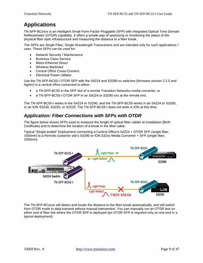
Application: Fiber Connections with SFPs with OTDR The figure below shows SFPs used to measure the length of optical fiber cables at installation (Birth Certificate) and to determine the location of a break in the fiber cable.
Typical “Single-ended” Deployment connecting a Central Office’s S4224 + OTDR SFP (single fiber, 1550nm) to a Remote customer site’s S3290 or ION S32xx Media Converter + SFP (single fiber, 1550nm).
The TN-SFP-BCxxxx will detect and locate the distance to the fiber break automatically, and will switch from OTDR mode to data transmit without manual intervention. You can manually run an OTDR test on either end of fiber link where the OTDR SFP is deployed (an OTDR SFP is required only on one end in a typical deployment).
Transition Networks TN-SFP-BC55 and TN-SFP-BC55-I User Guide
33669 Rev. A http://www.transition.com/ Page 10 of 47
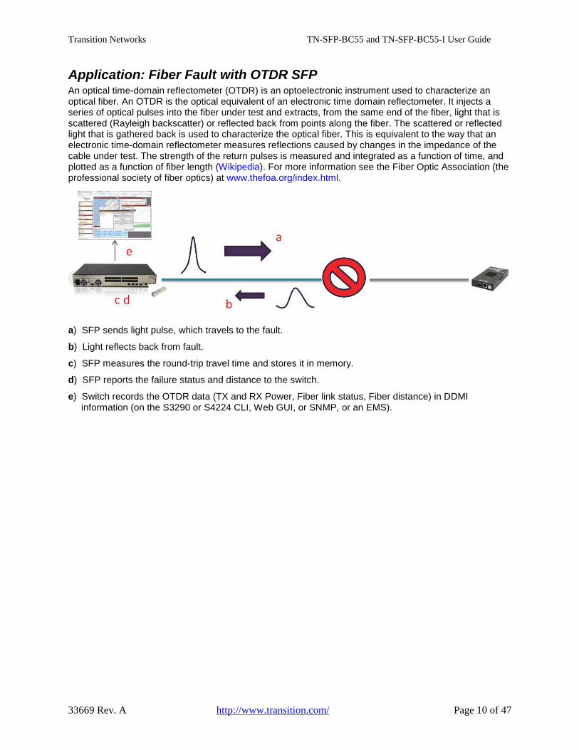
Application: Fiber Fault with OTDR SFP An optical time-domain reflectometer (OTDR) is an optoelectronic instrument used to characterize an optical fiber. An OTDR is the optical equivalent of an electronic time domain reflectometer. It injects a series of optical pulses into the fiber under test and extracts, from the same end of the fiber, light that is scattered (Rayleigh backscatter) or reflected back from points along the fiber. The scattered or reflected light that is gathered back is used to characterize the optical fiber. This is equivalent to the way that an electronic time-domain reflectometer measures reflections caused by changes in the impedance of the cable under test. The strength of the return pulses is measured and integrated as a function of time, and plotted as a function of fiber length (Wikipedia). For more information see the Fiber Optic Association (the professional society of fiber optics) at www.thefoa.org/index.html.
a) SFP sends light pulse, which travels to the fault.
b) Light reflects back from fault.
c) SFP measures the round-trip travel time and stores it in memory.
d) SFP reports the failure status and distance to the switch.
e) Switch records the OTDR data (TX and RX Power, Fiber link status, Fiber distance) in DDMI information (on the S3290 or S4224 CLI, Web GUI, or SNMP, or an EMS).
Transition Networks TN-SFP-BC55 and TN-SFP-BC55-I User Guide
33669 Rev. A http://www.transition.com/ Page 11 of 47
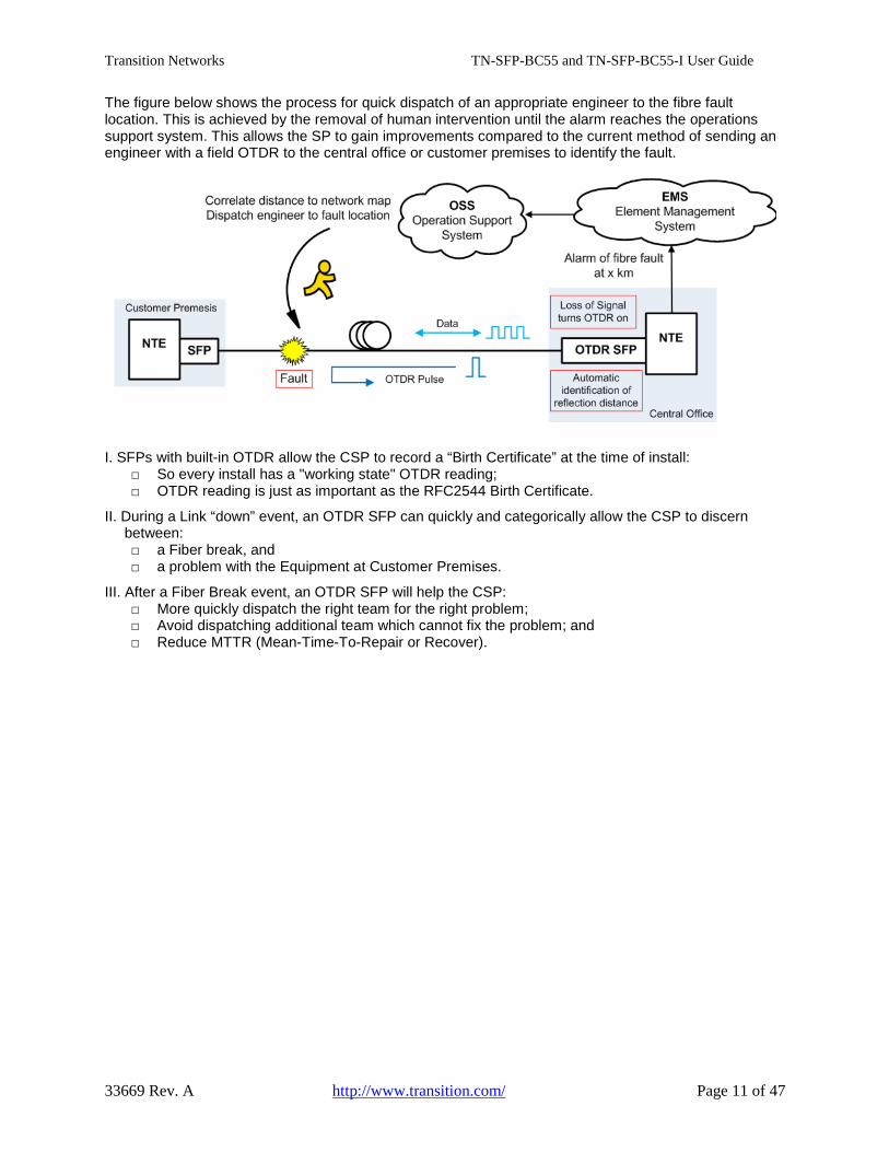
The figure below shows the process for quick dispatch of an appropriate engineer to the fibre fault location. This is achieved by the removal of human intervention until the alarm reaches the operations support system. This allows the SP to gain improvements compared to the current method of sending an engineer with a field OTDR to the central office or customer premises to identify the fault.
I. SFPs with built-in OTDR allow the CSP to record a “Birth Certificate” at the time of install: □ So every install has a "working state" OTDR reading; □ OTDR reading is just as important as the RFC2544 Birth Certificate.
II. During a Link “down” event, an OTDR SFP can quickly and categorically allow the CSP to discern between: □ a Fiber break, and □ a problem with the Equipment at Customer Premises.
III. After a Fiber Break event, an OTDR SFP will help the CSP: □ More quickly dispatch the right team for the right problem; □ Avoid dispatching additional team which cannot fix the problem; and □ Reduce MTTR (Mean-Time-To-Repair or Recover).
Transition Networks TN-SFP-BC55 and TN-SFP-BC55-I User Guide
33669 Rev. A http://www.transition.com/ Page 12 of 47
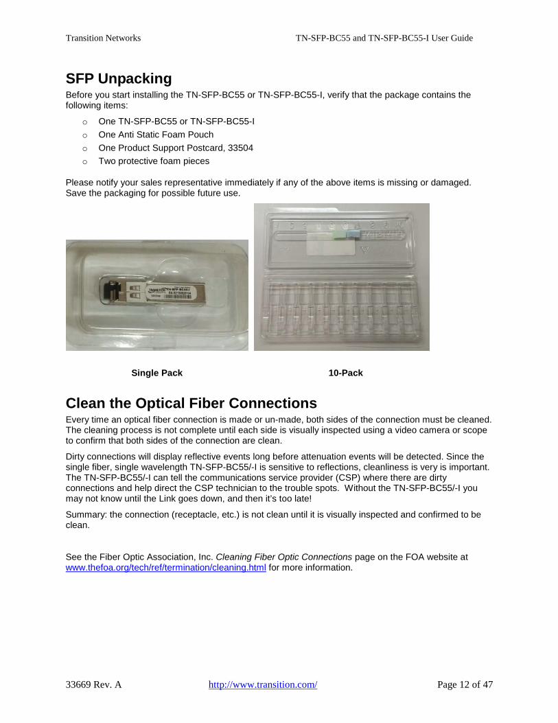
SFP Unpacking Before you start installing the TN-SFP-BC55 or TN-SFP-BC55-I, verify that the package contains the following items:
o One TN-SFP-BC55 or TN-SFP-BC55-I o One Anti Static Foam Pouch o One Product Support Postcard, 33504 o Two protective foam pieces
Please notify your sales representative immediately if any of the above items is missing or damaged. Save the packaging for possible future use.
Single Pack 10-Pack
Clean the Optical Fiber Connections Every time an optical fiber connection is made or un-made, both sides of the connection must be cleaned. The cleaning process is not complete until each side is visually inspected using a video camera or scope to confirm that both sides of the connection are clean.
Dirty connections will display reflective events long before attenuation events will be detected. Since the single fiber, single wavelength TN-SFP-BC55/-I is sensitive to reflections, cleanliness is very is important. The TN-SFP-BC55/-I can tell the communications service provider (CSP) where there are dirty connections and help direct the CSP technician to the trouble spots. Without the TN-SFP-BC55/-I you may not know until the Link goes down, and then it’s too late!
Summary: the connection (receptacle, etc.) is not clean until it is visually inspected and confirmed to be clean.
See the Fiber Optic Association, Inc. Cleaning Fiber Optic Connections page on the FOA website at www.thefoa.org/tech/ref/termination/cleaning.html for more information.

Transition Networks TN-SFP-BC55 and TN-SFP-BC55-I User Guide
33669 Rev. A http://www.transition.com/ Page 13 of 47
Cleaning Process: Inspect, Clean, Re-inspect, Connect Fiber inspection and cleaning are simple steps with immense benefits.
Always inspect both connectors before mating. Mating dirty connectors will cross-contaminate both connectors. Hard contaminates will scratch and pit the ferrule end face. Inspect before mating to prevent permanent damage to connectors, reduce troubleshooting time, reduce material costs, and improve signal quality.
Make fiber optic cleanliness a priority. Develop inspection and cleaning procedures, and train your team regularly on how to inspect and clean your connectors.
Cleaning Best Practices: Many tools exist to clean fiber. Many companies have their own “best practices”. Dry clean first, then try wet cleaning. Always finish with a dry cleaning process.
Important Standards Regarding End Face Quality and Cleaning
• IEC 61300-3-35: Fibre Optic Interconnecting Devices and Passive Components – Basic Test and Measurement Procedures
• IPC 8497-1: Cleaning Methods and Contamination Assessment for Optical Assembly
• IEC 62627 (DTR): Fibre Optic Interconnecting Devices and Passive Components – Fibre Optic Connector Cleaning Methods
• IEC 61300-3-3 has developed zones for setting requirements for connector’s endface quality.
• IEC 62627 – DTR scope is intended to emphasize the need for cleaning fibre optic connectors as well as describing the some of the current tools and methods for proper cleaning.
• IPC-8497-1 scope is intended to describe the methods of inspecting and cleaning all optical interfaces so their interconnectivity does not result in loss of optical signal. (IPC-8497-1 is a summary of both IEC standards (IEC 62627 – DTR and IPC-8497-1).
The IEC Standards are available for download from several sources including the ANSI Standards Store.

Transition Networks TN-SFP-BC55 and TN-SFP-BC55-I User Guide
33669 Rev. A http://www.transition.com/ Page 14 of 47
SFP Installation
Cautions • The SFP tranceiver module is keyed to only be installed one way. However, if forced the wrong way,
damage may occur. See S4224 Note below for SFP port orientation. • Avoid getting dust or other contaminants into the fiber bore of the SFP transceiver module, as this will
cause the optics to not operate properly. • Clean the optic surfaces of the optical fiber before you plug them back in to the optical bores of
another SFP tranceiver module. • Each port must match the wavelength specifications on the other end of the cable, and the cable
must not exceed the specified cable length for reliable communications.
Installing an SFP Module 1. Attach an ESD-preventive wrist strap to your wrist and to the ESD ground connector or a bare metal
surface on your chassis.
2. Remove the SFP transceiver module from its protective packaging. Note: Do not remove the optical bore dust plugs until directed to do so in a later procedure.
3. Check the slot orientation. S4224 Note: odd numbered SFP slots are “upside down” compared to even numbered slots.
4. Position the SFP device at the desired installation slot, with the label facing correctly. 5. Carefully slide the SFP device into the slot, aligning it with the internal installation guides.
Triangle indicates bottom
of SFP cage
SFP Module
Label side top of SFP module
Bale Clasp
Switch
Fully Inserted SFP
Switch
6. Ensure that the SFP device is firmly seated against the internal mating connector. To verify that the
SFP is seated and latched properly. a) Grasp the SFP by the sides and try to remove it without releasing the latch. b) If the SFP can not be removed, it is installed and seated properly. If the SFP can be removed, reinsert it and press harder with your thumb; repeat if necessary until it is latched securely into the socket.
7. Connect the fiber cable to the fiber port connector of the SFP device. Make sure the SFP release
latch is in the up (closed) position when you insert the cable connector into the SFP. 8. Remove the dust plug from the connector. Save the dust plug for future use. 9. Attach an appropriate cable into the SFP module port. 10. Attach the other end of the cable into the other device. 11. Observe the connected device’s status LED(s). See the related manual for details.
Transition Networks TN-SFP-BC55 and TN-SFP-BC55-I User Guide
33669 Rev. A http://www.transition.com/ Page 15 of 47
Fiber Cable Physical Characteristics The fiber cable physical characteristics must meet or exceed IEEE 802.3ae specifications:
• Single mode fiber (recommended): 9 μm • Multimode not recommended
Warning: Visible and invisible laser radiation when open. DO NOT stare into laser beam or view directly with optical instruments. Failure to observe this warning could result in damage to your eyes or blindness.
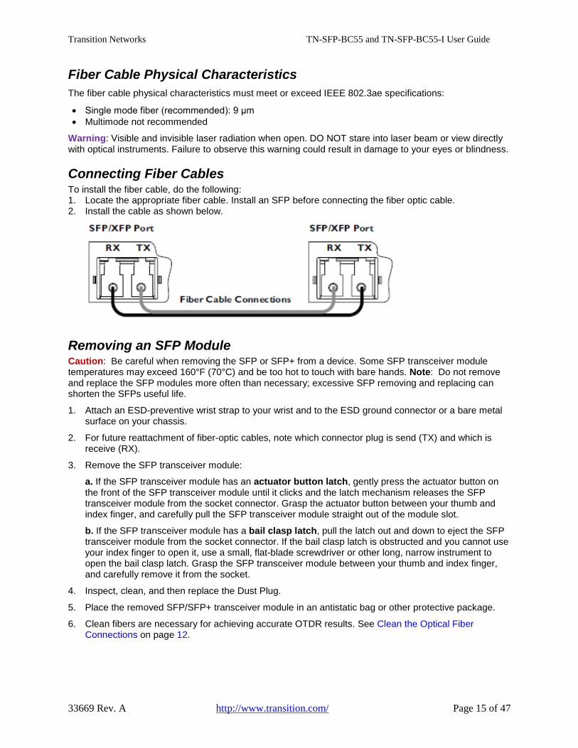
Connecting Fiber Cables To install the fiber cable, do the following: 1. Locate the appropriate fiber cable. Install an SFP before connecting the fiber optic cable. 2. Install the cable as shown below.
Removing an SFP Module Caution: Be careful when removing the SFP or SFP+ from a device. Some SFP transceiver module temperatures may exceed 160°F (70°C) and be too hot to touch with bare hands. Note: Do not remove and replace the SFP modules more often than necessary; excessive SFP removing and replacing can shorten the SFPs useful life.
1. Attach an ESD-preventive wrist strap to your wrist and to the ESD ground connector or a bare metal surface on your chassis.
2. For future reattachment of fiber-optic cables, note which connector plug is send (TX) and which is receive (RX).
3. Remove the SFP transceiver module:
a. If the SFP transceiver module has an actuator button latch, gently press the actuator button on the front of the SFP transceiver module until it clicks and the latch mechanism releases the SFP transceiver module from the socket connector. Grasp the actuator button between your thumb and index finger, and carefully pull the SFP transceiver module straight out of the module slot.
b. If the SFP transceiver module has a bail clasp latch, pull the latch out and down to eject the SFP transceiver module from the socket connector. If the bail clasp latch is obstructed and you cannot use your index finger to open it, use a small, flat-blade screwdriver or other long, narrow instrument to open the bail clasp latch. Grasp the SFP transceiver module between your thumb and index finger, and carefully remove it from the socket.
4. Inspect, clean, and then replace the Dust Plug.
5. Place the removed SFP/SFP+ transceiver module in an antistatic bag or other protective package.
6. Clean fibers are necessary for achieving accurate OTDR results. See Clean the Optical Fiber Connections on page 12.
Transition Networks TN-SFP-BC55 and TN-SFP-BC55-I User Guide
33669 Rev. A http://www.transition.com/ Page 16 of 47
Prerequisites and Restrictions This section provides configuration prerequisites and restrictions. For the latest feature information and caveats, see the release notes for your particular device and software release. The prerequisites and restrictions below apply to both the S3290 and the S4224 unless otherwise noted.
NTP Server An NTP server is required for accurate timestamping. NTP is configurable via the S3290 and the S4224 web GUI and/or CLI.
NTP (Network Time Protocol) is a protocol for synchronizing the clocks of computer systems over packet-switched, variable-latency data networks. The NTP system is used primarily when data transfer is handled via the Internet.
If NTP is not configured, then the Timestamp will be the device default of the year 1970 and the elapsed time since last reboot.
If your S3290 or S4224already has an NTP server, see the S3290 or S4224 Web User Guide or CLI Reference for NTP configuration vuia the web UI or CLI.
If your system does not already have an NTP server, there are several dowload options available:
The NTP Pool Project home page is at http://www.pool.ntp.org/en/.
See the NTP Terms of Service at http://www.pool.ntp.org/tos.html.
Additional Resources The home of the Network Time Protocol project R&D is ntp.org (http://www.ntp.org/).
The United States NTP Pool - us.pool.ntp.org is at http://www.pool.ntp.org/zone/us.
The NIST Internet Time Servers webpage lists the time servers used by the NIST Internet Time Service (ITS) at http://tf.nist.gov/tf-cgi/servers.cgi.
OTDR SFP Behavior The TN-SFP-BCxx-I works in the S4224 and S3290; the TN-SFP-BCxx works in the S4224, S3290, S3230, S3220, and S2220. The TN-SFP-BCxx can work with any SFP slot of the device which complies to the MSA standard (SFF-8472), such as Switches, NID and Media converters.
The OTDR SFP can be identifed in the DMI module of all supported devices.
The OTDR SFP operates at the specified wavelengths per the accepted ITU CWDM wavelengths (1271, 1291, 1311, 1331, 1351, 1371, 1391, 1411, 1431, 1451, 1471, 1491, 1511, 1531, 1551, 1571, 1591, 1611).
The OTDR SFP only accepts SC/UPC or LC/UPC connector types.
An OTDR Test is run every time the supported device is powered up and OTDR is run by the OTDR SFP (warm start/cold start). You can initiate cold start and warm restart and verify the OTDR test result via Web, CLI, and SNMP.
No OTDR Test is run when the link is up, since the OTDR test turns off data transmission.
An OTDR Test is run one time when the link goes down (fiber break, remote SFP pulled, remote device loses power) and the OTDR test is run by the OTDR SFP.
The OTDR information is displayed on the Device per port via Web, CLI, and SNMP (Device ID (system name, Device Serial number IP, MAC address, port #), OTDR SFP Part number, and Serial number, Date and time per OTDR data set, Tx Power, Rx Power, and all reflections).
Transition Networks TN-SFP-BC55 and TN-SFP-BC55-I User Guide
33669 Rev. A http://www.transition.com/ Page 17 of 47
An OTDR Test displays multiple (up to 16) reflections on the supported Device via Web, CLI, and SNMP.
An OTDR Test produces and displays multiple sets (10 data sets plus Birth certificate) of OTDR data per Device port that has an OTDR SFP in it on the supported Device via Web, CLI, and SNMP.
You can view and delete multiple reflections (up to 16) on the supported Device via Web, CLI, and SNMP.
You can view a Timestamp in OTDR data sets via Web, CLI, and SNMP. NTP or another supported timing protocol can be configured so that a timestamp can be viewed on each set of OTDR data.
You can set via Web, CLI, and SNMP one of the data sets as the original “birth certificate” and it will not be overwritten unless you chose to overwrite it.
You can overwrite (change) the “birth certificate” data on the Device via Web, CLI, and SNMP if there is a change in the network configuration.
You can download and store the OTDR information per port as a .PDF file to a local computer via Web, CLI, and SNMP. The content of the download file is the same content as webpage.
The OTDR SFP will send an SNMP trap with OTDR data that you can receive on a trap receiver (EMS/NMS, etc.).
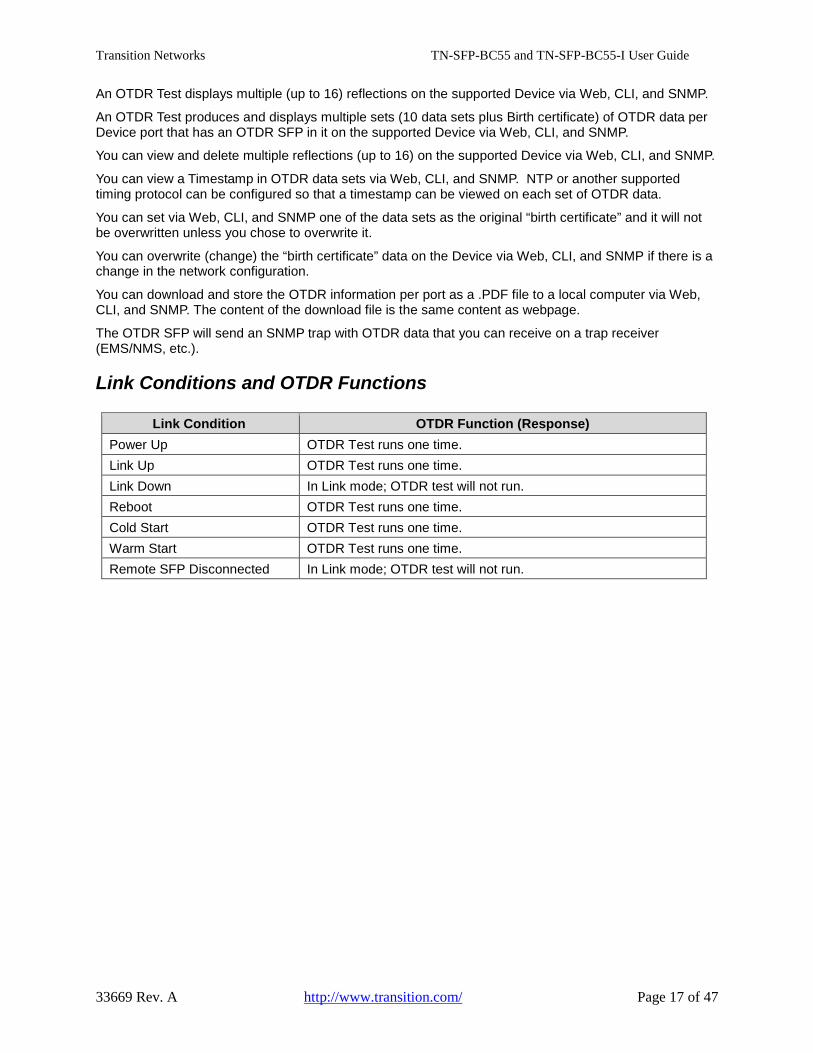
Link Conditions and OTDR Functions
Link Condition OTDR Function (Response) Power Up OTDR Test runs one time. Link Up OTDR Test runs one time. Link Down In Link mode; OTDR test will not run. Reboot OTDR Test runs one time. Cold Start OTDR Test runs one time. Warm Start OTDR Test runs one time. Remote SFP Disconnected In Link mode; OTDR test will not run.
Transition Networks TN-SFP-BC55 and TN-SFP-BC55-I User Guide
33669 Rev. A http://www.transition.com/ Page 18 of 47
Configuration via Web Interface This section shows and describes the S4224 DDMI OTDR web interface. The web interface for the S3290 is nearly identical; differences are noted where they occur.
DDMI (Digital Diagnostic Monitoring Interface) The following DMI port screen and explanation table contains brief definitions of the DMI support offered on some SFP Transceiver Modules. Note: This feature is not available on all devices and may vary between products. Note: S3290 or S4224 firmware version v2.2.5 is required. See the related S3290 or S4224 manual for more information.
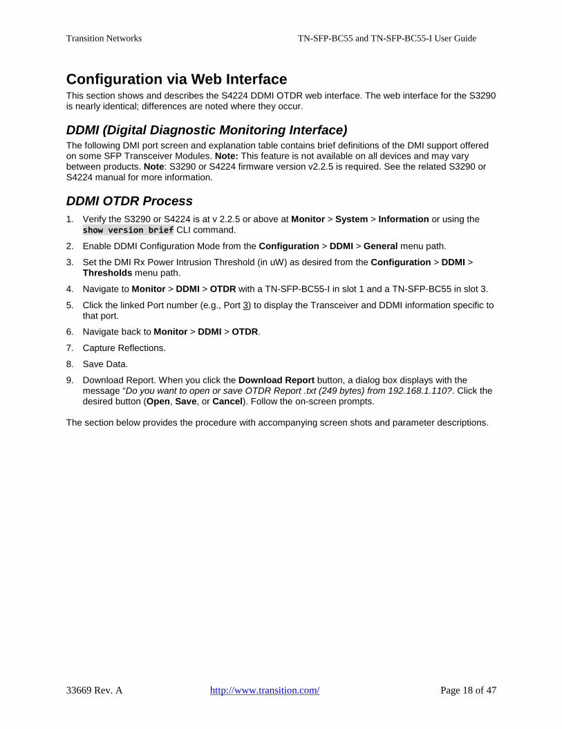
DDMI OTDR Process 1. Verify the S3290 or S4224 is at v 2.2.5 or above at Monitor > System > Information or using the
show version brief CLI command.
2. Enable DDMI Configuration Mode from the Configuration > DDMI > General menu path.
3. Set the DMI Rx Power Intrusion Threshold (in uW) as desired from the Configuration > DDMI > Thresholds menu path.
4. Navigate to Monitor > DDMI > OTDR with a TN-SFP-BC55-I in slot 1 and a TN-SFP-BC55 in slot 3.
5. Click the linked Port number (e.g., Port 3) to display the Transceiver and DDMI information specific to that port.
6. Navigate back to Monitor > DDMI > OTDR.
7. Capture Reflections.
8. Save Data.
9. Download Report. When you click the Download Report button, a dialog box displays with the message “Do you want to open or save OTDR Report .txt (249 bytes) from 192.168.1.110?. Click the desired button (Open, Save, or Cancel). Follow the on-screen prompts.
The section below provides the procedure with accompanying screen shots and parameter descriptions.
Transition Networks TN-SFP-BC55 and TN-SFP-BC55-I User Guide
33669 Rev. A http://www.transition.com/ Page 19 of 47
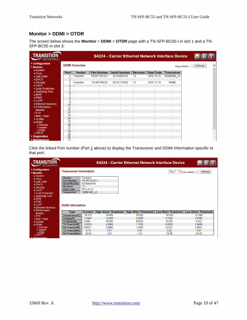
Monitor > DDMI > OTDR The screen below shows the Monitor > DDMI > OTDR page with a TN-SFP-BC55-I in slot 1 and a TN-SFP-BC55 in slot 3:
Click the linked Port number (Port 1 above) to display the Transceiver and DDMI Information specific to that port.
Transition Networks TN-SFP-BC55 and TN-SFP-BC55-I User Guide
33669 Rev. A http://www.transition.com/ Page 20 of 47
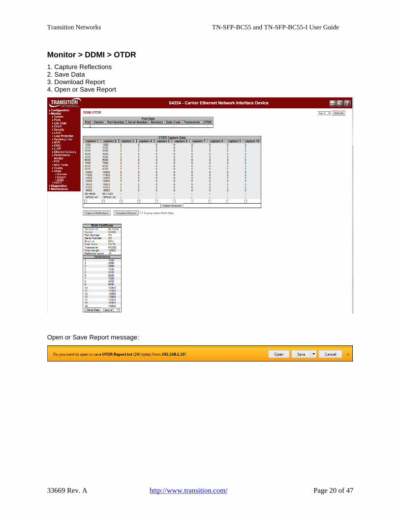
Monitor > DDMI > OTDR 1. Capture Reflections 2. Save Data 3. Download Report 4. Open or Save Report
Open or Save Report message:
Transition Networks TN-SFP-BC55 and TN-SFP-BC55-I User Guide
33669 Rev. A http://www.transition.com/ Page 21 of 47
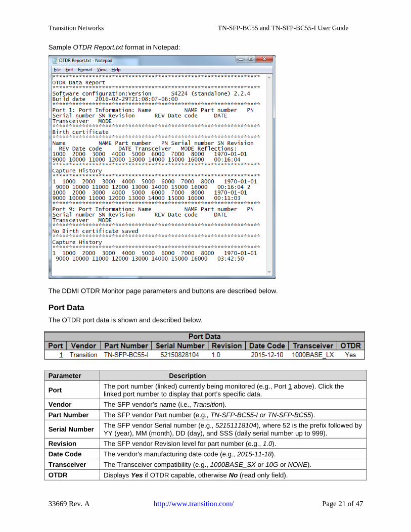
Sample OTDR Report.txt format in Notepad:
The DDMI OTDR Monitor page parameters and buttons are described below.
Port Data The OTDR port data is shown and described below.
Parameter Description
Port The port number (linked) currently being monitored (e.g., Port 1 above). Click the linked port number to display that port’s specific data.
Vendor The SFP vendor’s name (i.e., Transition). Part Number The SFP vendor Part number (e.g., TN-SFP-BC55-I or TN-SFP-BC55).
Serial Number The SFP vendor Serial number (e.g., 52151118104), where 52 is the prefix followed by YY (year), MM (month), DD (day), and SSS (daily serial number up to 999).
Revision The SFP vendor Revision level for part number (e.g., 1.0). Date Code The vendor's manufacturing date code (e.g., 2015-11-18). Transceiver The Transceiver compatibility (e.g., 1000BASE_SX or 10G or NONE). OTDR Displays Yes if OTDR capable, otherwise No (read only field).
Transition Networks TN-SFP-BC55 and TN-SFP-BC55-I User Guide
33669 Rev. A http://www.transition.com/ Page 22 of 47
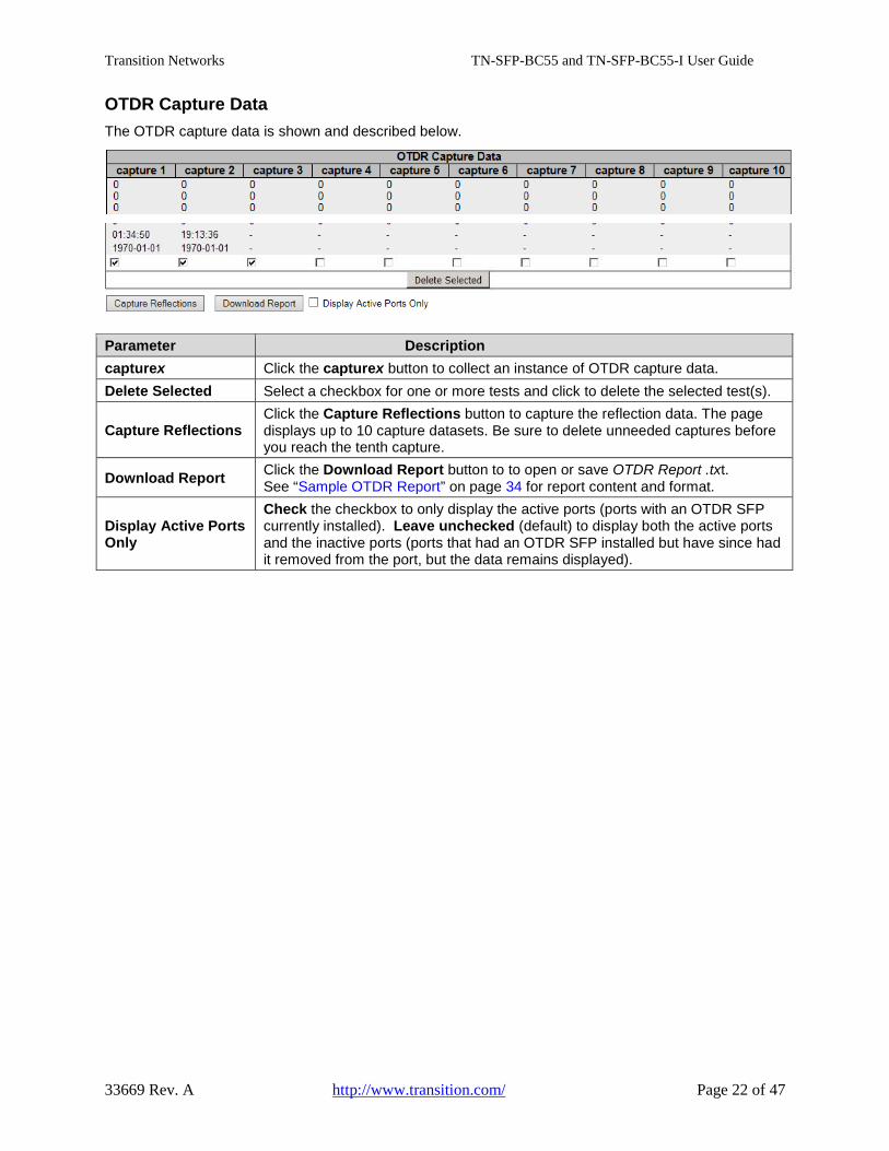
OTDR Capture Data The OTDR capture data is shown and described below.
Parameter Description capturex Click the capturex button to collect an instance of OTDR capture data. Delete Selected Select a checkbox for one or more tests and click to delete the selected test(s).
Capture Reflections Click the Capture Reflections button to capture the reflection data. The page displays up to 10 capture datasets. Be sure to delete unneeded captures before you reach the tenth capture.
Download Report Click the Download Report button to to open or save OTDR Report .txt. See “Sample OTDR Report” on page 34 for report content and format.
Display Active Ports Only
Check the checkbox to only display the active ports (ports with an OTDR SFP currently installed). Leave unchecked (default) to display both the active ports and the inactive ports (ports that had an OTDR SFP installed but have since had it removed from the port, but the data remains displayed).
Transition Networks TN-SFP-BC55 and TN-SFP-BC55-I User Guide
33669 Rev. A http://www.transition.com/ Page 23 of 47
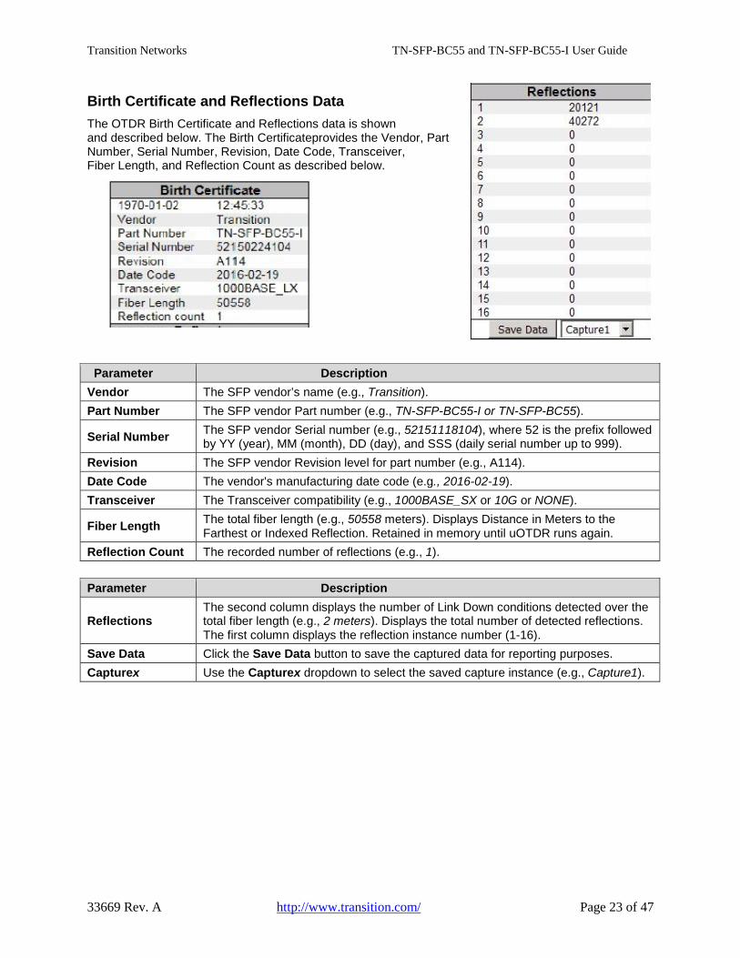
Birth Certificate and Reflections Data The OTDR Birth Certificate and Reflections data is shown and described below. The Birth Certificateprovides the Vendor, Part Number, Serial Number, Revision, Date Code, Transceiver, Fiber Length, and Reflection Count as described below.
Parameter Description Vendor The SFP vendor’s name (e.g., Transition). Part Number The SFP vendor Part number (e.g., TN-SFP-BC55-I or TN-SFP-BC55).
Serial Number The SFP vendor Serial number (e.g., 52151118104), where 52 is the prefix followed by YY (year), MM (month), DD (day), and SSS (daily serial number up to 999).
Revision The SFP vendor Revision level for part number (e.g., A114). Date Code The vendor's manufacturing date code (e.g., 2016-02-19). Transceiver The Transceiver compatibility (e.g., 1000BASE_SX or 10G or NONE).
Fiber Length The total fiber length (e.g., 50558 meters). Displays Distance in Meters to the Farthest or Indexed Reflection. Retained in memory until uOTDR runs again.
Reflection Count The recorded number of reflections (e.g., 1). Parameter Description
Reflections The second column displays the number of Link Down conditions detected over the total fiber length (e.g., 2 meters). Displays the total number of detected reflections. The first column displays the reflection instance number (1-16).
Save Data Click the Save Data button to save the captured data for reporting purposes. Capturex Use the Capturex dropdown to select the saved capture instance (e.g., Capture1).
Transition Networks TN-SFP-BC55 and TN-SFP-BC55-I User Guide
33669 Rev. A http://www.transition.com/ Page 24 of 47
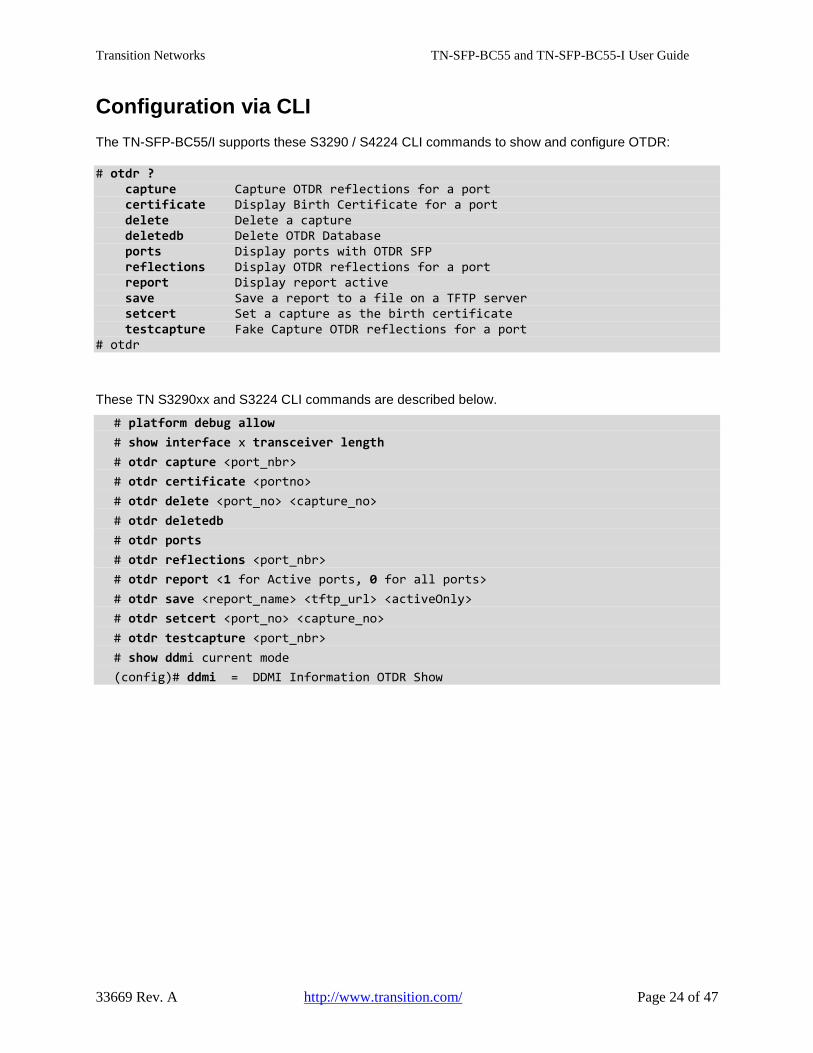
Configuration via CLI The TN-SFP-BC55/I supports these S3290 / S4224 CLI commands to show and configure OTDR:
# otdr ? capture Capture OTDR reflections for a port certificate Display Birth Certificate for a port delete Delete a capture deletedb Delete OTDR Database ports Display ports with OTDR SFP reflections Display OTDR reflections for a port report Display report active save Save a report to a file on a TFTP server setcert Set a capture as the birth certificate testcapture Fake Capture OTDR reflections for a port # otdr
These TN S3290xx and S3224 CLI commands are described below.
# platform debug allow # show interface x transceiver length # otdr capture <port_nbr> # otdr certificate <portno> # otdr delete <port_no> <capture_no> # otdr deletedb # otdr ports # otdr reflections <port_nbr> # otdr report <1 for Active ports, 0 for all ports> # otdr save <report_name> <tftp_url> <activeOnly> # otdr setcert <port_no> <capture_no> # otdr testcapture <port_nbr> # show ddmi current mode (config)# ddmi = DDMI Information OTDR Show
Transition Networks TN-SFP-BC55 and TN-SFP-BC55-I User Guide
33669 Rev. A http://www.transition.com/ Page 25 of 47
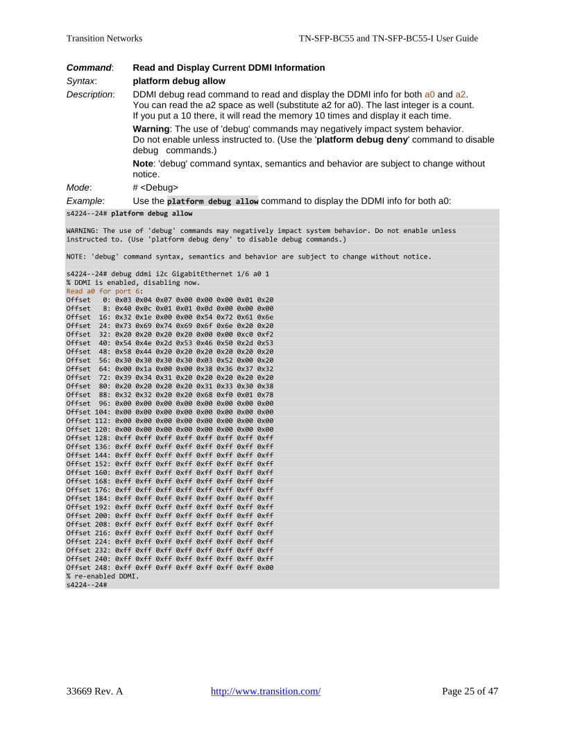
Command: Read and Display Current DDMI Information Syntax: platform debug allow Description: DDMI debug read command to read and display the DDMI info for both a0 and a2. You can read the a2 space as well (substitute a2 for a0). The last integer is a count. If you put a 10 there, it will read the memory 10 times and display it each time. Warning: The use of 'debug' commands may negatively impact system behavior. Do not enable unless instructed to. (Use the 'platform debug deny' command to disable debug commands.) Note: 'debug' command syntax, semantics and behavior are subject to change without notice. Mode: # <Debug> Example: Use the platform debug allow command to display the DDMI info for both a0: s4224--24# platform debug allow WARNING: The use of 'debug' commands may negatively impact system behavior. Do not enable unless instructed to. (Use 'platform debug deny' to disable debug commands.) NOTE: 'debug' command syntax, semantics and behavior are subject to change without notice. s4224--24# debug ddmi i2c GigabitEthernet 1/6 a0 1 % DDMI is enabled, disabling now. Read a0 for port 6: Offset 0: 0x03 0x04 0x07 0x00 0x00 0x00 0x01 0x20 Offset 8: 0x40 0x0c 0x01 0x01 0x0d 0x00 0x00 0x00 Offset 16: 0x32 0x1e 0x00 0x00 0x54 0x72 0x61 0x6e Offset 24: 0x73 0x69 0x74 0x69 0x6f 0x6e 0x20 0x20 Offset 32: 0x20 0x20 0x20 0x20 0x00 0x00 0xc0 0xf2 Offset 40: 0x54 0x4e 0x2d 0x53 0x46 0x50 0x2d 0x53 Offset 48: 0x58 0x44 0x20 0x20 0x20 0x20 0x20 0x20 Offset 56: 0x30 0x30 0x30 0x30 0x03 0x52 0x00 0x20 Offset 64: 0x00 0x1a 0x00 0x00 0x38 0x36 0x37 0x32 Offset 72: 0x39 0x34 0x31 0x20 0x20 0x20 0x20 0x20 Offset 80: 0x20 0x20 0x20 0x20 0x31 0x33 0x30 0x38 Offset 88: 0x32 0x32 0x20 0x20 0x68 0xf0 0x01 0x78 Offset 96: 0x00 0x00 0x00 0x00 0x00 0x00 0x00 0x00 Offset 104: 0x00 0x00 0x00 0x00 0x00 0x00 0x00 0x00 Offset 112: 0x00 0x00 0x00 0x00 0x00 0x00 0x00 0x00 Offset 120: 0x00 0x00 0x00 0x00 0x00 0x00 0x00 0x00 Offset 128: 0xff 0xff 0xff 0xff 0xff 0xff 0xff 0xff Offset 136: 0xff 0xff 0xff 0xff 0xff 0xff 0xff 0xff Offset 144: 0xff 0xff 0xff 0xff 0xff 0xff 0xff 0xff Offset 152: 0xff 0xff 0xff 0xff 0xff 0xff 0xff 0xff Offset 160: 0xff 0xff 0xff 0xff 0xff 0xff 0xff 0xff Offset 168: 0xff 0xff 0xff 0xff 0xff 0xff 0xff 0xff Offset 176: 0xff 0xff 0xff 0xff 0xff 0xff 0xff 0xff Offset 184: 0xff 0xff 0xff 0xff 0xff 0xff 0xff 0xff Offset 192: 0xff 0xff 0xff 0xff 0xff 0xff 0xff 0xff Offset 200: 0xff 0xff 0xff 0xff 0xff 0xff 0xff 0xff Offset 208: 0xff 0xff 0xff 0xff 0xff 0xff 0xff 0xff Offset 216: 0xff 0xff 0xff 0xff 0xff 0xff 0xff 0xff Offset 224: 0xff 0xff 0xff 0xff 0xff 0xff 0xff 0xff Offset 232: 0xff 0xff 0xff 0xff 0xff 0xff 0xff 0xff Offset 240: 0xff 0xff 0xff 0xff 0xff 0xff 0xff 0xff Offset 248: 0xff 0xff 0xff 0xff 0xff 0xff 0xff 0x00 % re-enabled DDMI. s4224--24#
Transition Networks TN-SFP-BC55 and TN-SFP-BC55-I User Guide
33669 Rev. A http://www.transition.com/ Page 26 of 47
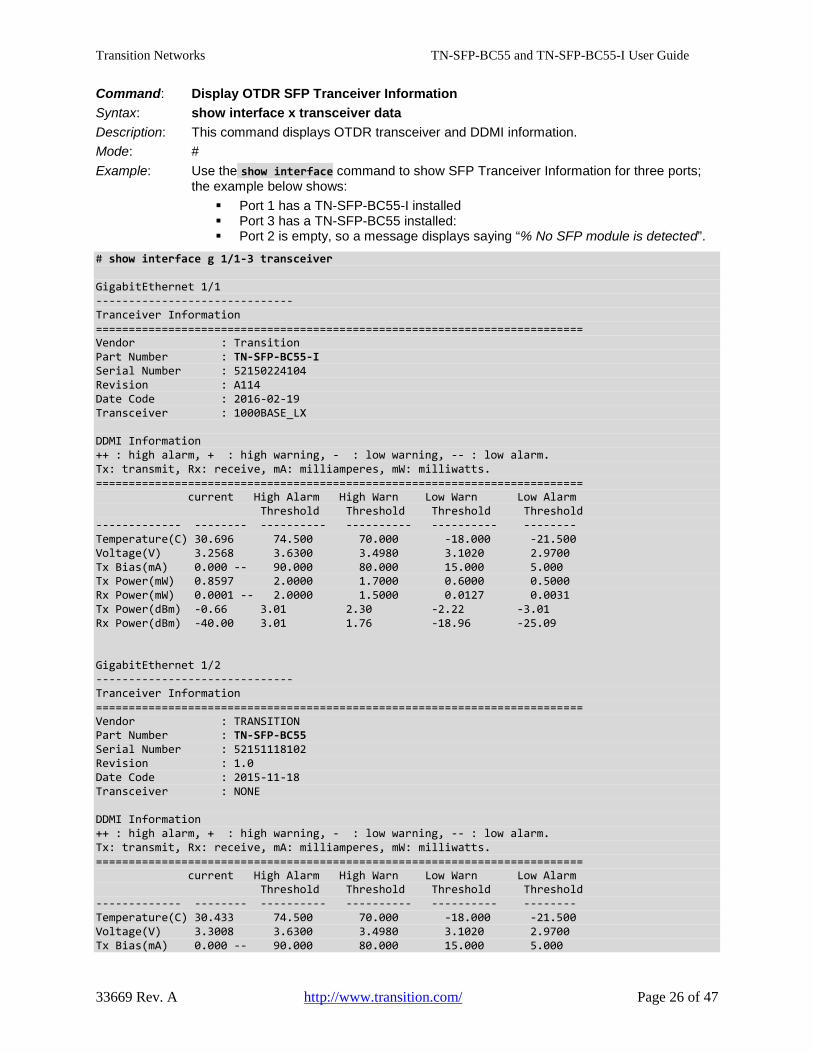
Command: Display OTDR SFP Tranceiver Information Syntax: show interface x transceiver data Description: This command displays OTDR transceiver and DDMI information. Mode: # Example: Use the show interface command to show SFP Tranceiver Information for three ports; the example below shows:
Port 1 has a TN-SFP-BC55-I installed Port 3 has a TN-SFP-BC55 installed: Port 2 is empty, so a message displays saying “% No SFP module is detected”.
# show interface g 1/1-3 transceiver GigabitEthernet 1/1 ------------------------------ Tranceiver Information ========================================================================== Vendor : Transition Part Number : TN-SFP-BC55-I Serial Number : 52150224104 Revision : A114 Date Code : 2016-02-19 Transceiver : 1000BASE_LX DDMI Information ++ : high alarm, + : high warning, - : low warning, -- : low alarm. Tx: transmit, Rx: receive, mA: milliamperes, mW: milliwatts. ========================================================================== current High Alarm High Warn Low Warn Low Alarm Threshold Threshold Threshold Threshold ------------- -------- ---------- ---------- ---------- -------- Temperature(C) 30.696 74.500 70.000 -18.000 -21.500 Voltage(V) 3.2568 3.6300 3.4980 3.1020 2.9700 Tx Bias(mA) 0.000 -- 90.000 80.000 15.000 5.000 Tx Power(mW) 0.8597 2.0000 1.7000 0.6000 0.5000 Rx Power(mW) 0.0001 -- 2.0000 1.5000 0.0127 0.0031 Tx Power(dBm) -0.66 3.01 2.30 -2.22 -3.01 Rx Power(dBm) -40.00 3.01 1.76 -18.96 -25.09 GigabitEthernet 1/2 ------------------------------ Tranceiver Information ========================================================================== Vendor : TRANSITION Part Number : TN-SFP-BC55 Serial Number : 52151118102 Revision : 1.0 Date Code : 2015-11-18 Transceiver : NONE DDMI Information ++ : high alarm, + : high warning, - : low warning, -- : low alarm. Tx: transmit, Rx: receive, mA: milliamperes, mW: milliwatts. ========================================================================== current High Alarm High Warn Low Warn Low Alarm Threshold Threshold Threshold Threshold ------------- -------- ---------- ---------- ---------- -------- Temperature(C) 30.433 74.500 70.000 -18.000 -21.500 Voltage(V) 3.3008 3.6300 3.4980 3.1020 2.9700 Tx Bias(mA) 0.000 -- 90.000 80.000 15.000 5.000
Transition Networks TN-SFP-BC55 and TN-SFP-BC55-I User Guide
33669 Rev. A http://www.transition.com/ Page 27 of 47
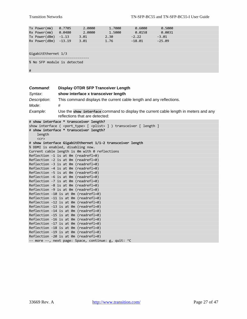
Tx Power(mW) 0.7705 2.0000 1.7000 0.6000 0.5000 Rx Power(mW) 0.0480 2.0000 1.5000 0.0158 0.0031 Tx Power(dBm) -1.13 3.01 2.30 -2.22 -3.01 Rx Power(dBm) -13.19 3.01 1.76 -18.01 -25.09 GigabitEthernet 1/3 ------------------------------ % No SFP module is detected #
Command: Display OTDR SFP Tranceiver Length Syntax: show interface x transceiver length Description: This command displays the current cable length and any reflections. Mode: # Example: Use the show interface command to display the current cable length in meters and any reflections that are detected: # show interface * transceiver length? show interface ( <port_type> [ <plist> ] ) transceiver [ length ] # show interface * transceiver length? length <cr> # show interface GigabitEthernet 1/1-2 transceiver length % DDMI is enabled, disabling now. Current cable length is 0m with 0 reflections Reflection -1 is at 0m (readrefl=0) Reflection -2 is at 0m (readrefl=0) Reflection -3 is at 0m (readrefl=0) Reflection -4 is at 0m (readrefl=0) Reflection -5 is at 0m (readrefl=0) Reflection -6 is at 0m (readrefl=0) Reflection -7 is at 0m (readrefl=0) Reflection -8 is at 0m (readrefl=0) Reflection -9 is at 0m (readrefl=0) Reflection -10 is at 0m (readrefl=0) Reflection -11 is at 0m (readrefl=0) Reflection -12 is at 0m (readrefl=0) Reflection -13 is at 0m (readrefl=0) Reflection -14 is at 0m (readrefl=0) Reflection -15 is at 0m (readrefl=0) Reflection -16 is at 0m (readrefl=0) Reflection -17 is at 0m (readrefl=0) Reflection -18 is at 0m (readrefl=0) Reflection -19 is at 0m (readrefl=0) Reflection -20 is at 0m (readrefl=0) -- more --, next page: Space, continue: g, quit: ^C
Transition Networks TN-SFP-BC55 and TN-SFP-BC55-I User Guide
33669 Rev. A http://www.transition.com/ Page 28 of 47
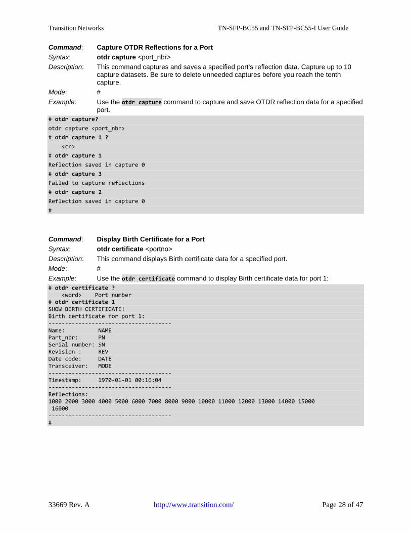
Command: Capture OTDR Reflections for a Port Syntax: otdr capture <port_nbr> Description: This command captures and saves a specified port’s reflection data. Capture up to 10 capture datasets. Be sure to delete unneeded captures before you reach the tenth capture. Mode: # Example: Use the otdr capture command to capture and save OTDR reflection data for a specified port. # otdr capture? otdr capture <port_nbr> # otdr capture 1 ? <cr> # otdr capture 1 Reflection saved in capture 0 # otdr capture 3 Failed to capture reflections # otdr capture 2 Reflection saved in capture 0 #
Command: Display Birth Certificate for a Port Syntax: otdr certificate <portno> Description: This command displays Birth certificate data for a specified port. Mode: # Example: Use the otdr certificate command to display Birth certificate data for port 1: # otdr certificate ? <word> Port number # otdr certificate 1 SHOW BIRTH CERTIFICATE! Birth certificate for port 1: ------------------------------------- Name: NAME Part_nbr: PN Serial number: SN Revision : REV Date code: DATE Transceiver: MODE ------------------------------------- Timestamp: 1970-01-01 00:16:04 ------------------------------------- Reflections: 1000 2000 3000 4000 5000 6000 7000 8000 9000 10000 11000 12000 13000 14000 15000 16000 ------------------------------------- #
Transition Networks TN-SFP-BC55 and TN-SFP-BC55-I User Guide
33669 Rev. A http://www.transition.com/ Page 29 of 47
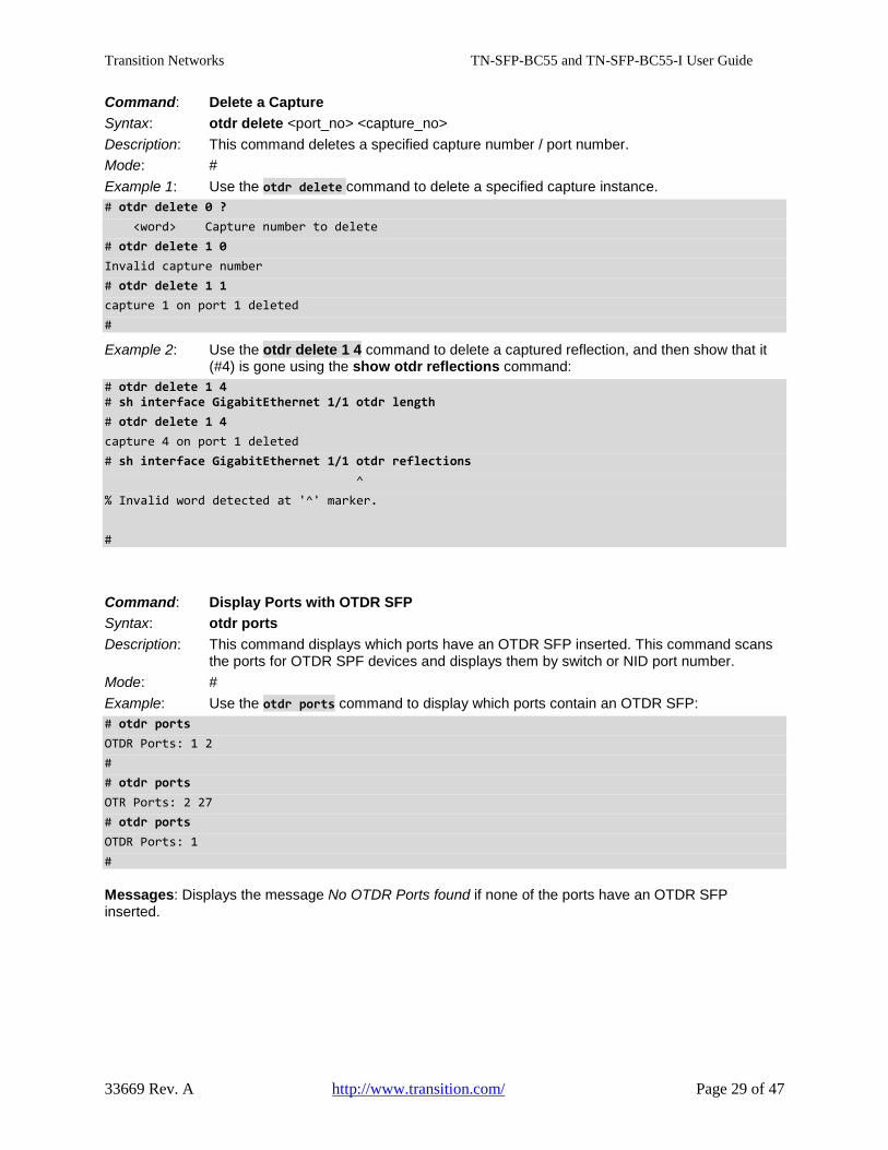
Command: Delete a Capture Syntax: otdr delete <port_no> <capture_no> Description: This command deletes a specified capture number / port number. Mode: # Example 1: Use the otdr delete command to delete a specified capture instance. # otdr delete 0 ? <word> Capture number to delete # otdr delete 1 0 Invalid capture number # otdr delete 1 1 capture 1 on port 1 deleted #
Example 2: Use the otdr delete 1 4 command to delete a captured reflection, and then show that it (#4) is gone using the show otdr reflections command: # otdr delete 1 4 # sh interface GigabitEthernet 1/1 otdr length # otdr delete 1 4 capture 4 on port 1 deleted # sh interface GigabitEthernet 1/1 otdr reflections ^ % Invalid word detected at '^' marker. #
Command: Display Ports with OTDR SFP Syntax: otdr ports Description: This command displays which ports have an OTDR SFP inserted. This command scans the ports for OTDR SPF devices and displays them by switch or NID port number. Mode: # Example: Use the otdr ports command to display which ports contain an OTDR SFP: # otdr ports OTDR Ports: 1 2 # # otdr ports OTR Ports: 2 27 # otdr ports OTDR Ports: 1 #
Messages: Displays the message No OTDR Ports found if none of the ports have an OTDR SFP inserted.
Transition Networks TN-SFP-BC55 and TN-SFP-BC55-I User Guide
33669 Rev. A http://www.transition.com/ Page 30 of 47
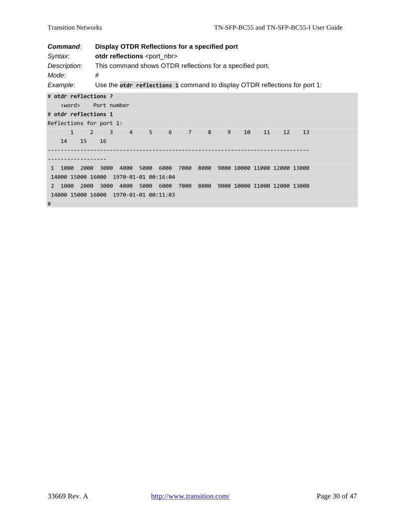
Command: Display OTDR Reflections for a specified port Syntax: otdr reflections <port_nbr> Description: This command shows OTDR reflections for a specified port. Mode: # Example: Use the otdr reflections 1 command to display OTDR reflections for port 1: # otdr reflections ? <word> Port number # otdr reflections 1 Reflections for port 1: 1 2 3 4 5 6 7 8 9 10 11 12 13 14 15 16 -------------------------------------------------------------------------------- ------------------ 1 1000 2000 3000 4000 5000 6000 7000 8000 9000 10000 11000 12000 13000 14000 15000 16000 1970-01-01 00:16:04 2 1000 2000 3000 4000 5000 6000 7000 8000 9000 10000 11000 12000 13000 14000 15000 16000 1970-01-01 00:11:03 #
Transition Networks TN-SFP-BC55 and TN-SFP-BC55-I User Guide
33669 Rev. A http://www.transition.com/ Page 31 of 47
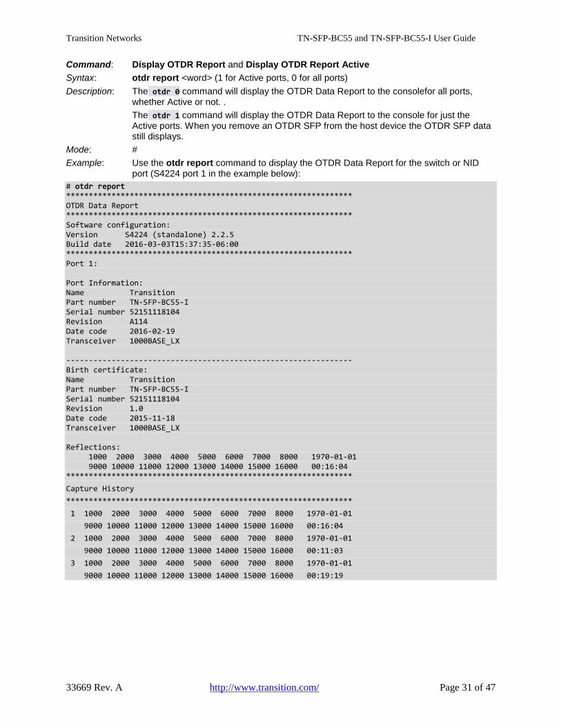
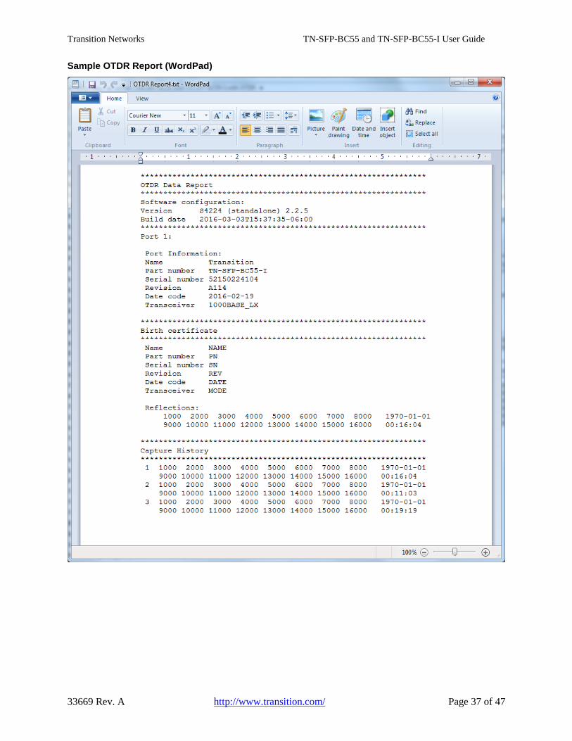
Command: Display OTDR Report and Display OTDR Report Active Syntax: otdr report <word> (1 for Active ports, 0 for all ports) Description: The otdr 0 command will display the OTDR Data Report to the consolefor all ports, whether Active or not. . The otdr 1 command will display the OTDR Data Report to the console for just the Active ports. When you remove an OTDR SFP from the host device the OTDR SFP data still displays. Mode: # Example: Use the otdr report command to display the OTDR Data Report for the switch or NID port (S4224 port 1 in the example below): # otdr report *************************************************************** OTDR Data Report *************************************************************** Software configuration: Version S4224 (standalone) 2.2.5 Build date 2016-03-03T15:37:35-06:00 *************************************************************** Port 1: Port Information: Name Transition Part number TN-SFP-BC55-I Serial number 52151118104 Revision A114 Date code 2016-02-19 Transceiver 1000BASE_LX --------------------------------------------------------------- Birth certificate: Name Transition Part number TN-SFP-BC55-I Serial number 52151118104 Revision 1.0 Date code 2015-11-18 Transceiver 1000BASE_LX Reflections: 1000 2000 3000 4000 5000 6000 7000 8000 1970-01-01 9000 10000 11000 12000 13000 14000 15000 16000 00:16:04 *************************************************************** Capture History *************************************************************** 1 1000 2000 3000 4000 5000 6000 7000 8000 1970-01-01 9000 10000 11000 12000 13000 14000 15000 16000 00:16:04 2 1000 2000 3000 4000 5000 6000 7000 8000 1970-01-01 9000 10000 11000 12000 13000 14000 15000 16000 00:11:03 3 1000 2000 3000 4000 5000 6000 7000 8000 1970-01-01 9000 10000 11000 12000 13000 14000 15000 16000 00:19:19
Transition Networks TN-SFP-BC55 and TN-SFP-BC55-I User Guide
33669 Rev. A http://www.transition.com/ Page 32 of 47
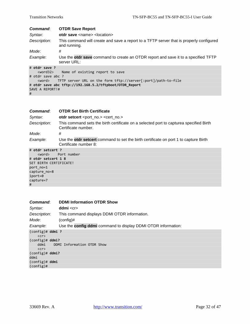
Command: OTDR Save Report Syntax: otdr save <name> <location> Description: This command will create and save a report to a TFTP server that is properly configured and running. Mode: # Example: Use the otdr save command to create an OTDR report and save it to a specified TFTP server URL: # otdr save ? <word32> Name of existing report to save # otdr save abc ? <word> TFTP server URL on the form tftp://server[:port]/path-to-file # otdr save abc tftp://192.168.5.2/tftpboot/OTDR_Report SAVE A REPORT!# #
Command: OTDR Set Birth Certificate Syntax: otdr setcert <port_no.> <cert_no.> Description: This command sets the birth certificate on a selected port to capturea specified Birth Certificate number. Mode: # Example: Use the otdr setcert command to set the birth certificate on port 1 to capture Birth Certificate number 8: # otdr setcert ? <word> Port number # otdr setcert 1 8 SET BIRTH CERTIFICATE! port_no=1 capture_no=8 iport=0 capture=7 #
Command: DDMI Information OTDR Show Syntax: ddmi <cr> Description: This command displays DDMI OTDR information. Mode: (config)# Example: Use the config ddmi command to display DDMI OTDR information: (config)# ddmi ? <cr> (config)# ddmi? ddmi DDMI Information OTDR Show <cr> (config)# ddmi? ddmi (config)# ddmi (config)#
Transition Networks TN-SFP-BC55 and TN-SFP-BC55-I User Guide
33669 Rev. A http://www.transition.com/ Page 33 of 47
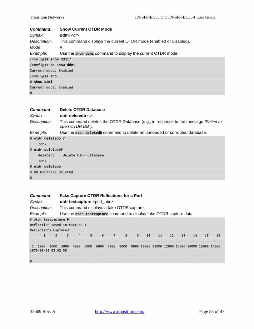
Command: Show Current OTDR Mode Syntax: ddmi <cr> Description: This command displays the current OTDR mode (enabled or disabled). Mode: # Example: Use the show ddmi command to display the current OTDR mode: (config)# show ddmi? (config)# do show ddmi Current mode: Enabled (config)# end # show ddmi Current mode: Enabled #
Command: Delete OTDR Database Syntax: otdr deletedb <> Description: This command deletes the OTDR Database (e.g., in response to the message “Failed to open OTDR DB”). Example: Use the otdr deletedb command to delete an unneeded or corrupted database. # otdr deletedb ? <cr> # otdr deletedb? deletedb Delete OTDR Database <cr> # otdr deletedb OTDR Database deleted #
Command: Fake Capture OTDR Reflections for a Port Syntax: otdr testcapture <port_nbr> Description: This command displays a fake OTDR capture. Example: Use the otdr testcapture command to display fake OTDR capture data: # otdr testcapture 9 Reflection saved in capture 1 Reflections Captured: 1 2 3 4 5 6 7 8 9 10 11 12 13 14 15 16 -------------------------------------------------------------------------------------------------- 1 1000 2000 3000 4000 5000 6000 7000 8000 9000 10000 11000 12000 13000 14000 15000 16000 1970-01-01 03:42:50 -------------------------------------------------------------------------------------------------- #
Transition Networks TN-SFP-BC55 and TN-SFP-BC55-I User Guide
33669 Rev. A http://www.transition.com/ Page 34 of 47
Configuration via SNMP A trap is set whenever a capture is generated with the physical port number of the OTDR SFP. Contact Transition Networks for additional information. See Contact Us on page 45.
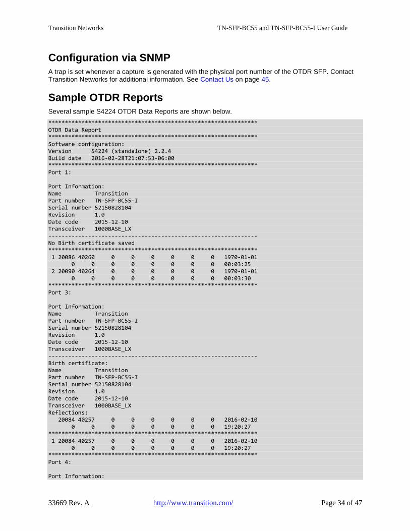
Sample OTDR Reports Several sample S4224 OTDR Data Reports are shown below. *************************************************************** OTDR Data Report *************************************************************** Software configuration: Version S4224 (standalone) 2.2.4 Build date 2016-02-28T21:07:53-06:00 *************************************************************** Port 1: Port Information: Name Transition Part number TN-SFP-BC55-I Serial number 52150828104 Revision 1.0 Date code 2015-12-10 Transceiver 1000BASE_LX --------------------------------------------------------------- No Birth certificate saved *************************************************************** 1 20086 40260 0 0 0 0 0 0 1970-01-01 0 0 0 0 0 0 0 0 00:03:25 2 20090 40264 0 0 0 0 0 0 1970-01-01 0 0 0 0 0 0 0 0 00:03:30 *************************************************************** Port 3: Port Information: Name Transition Part number TN-SFP-BC55-I Serial number 52150828104 Revision 1.0 Date code 2015-12-10 Transceiver 1000BASE_LX --------------------------------------------------------------- Birth certificate: Name Transition Part number TN-SFP-BC55-I Serial number 52150828104 Revision 1.0 Date code 2015-12-10 Transceiver 1000BASE_LX Reflections: 20084 40257 0 0 0 0 0 0 2016-02-10 0 0 0 0 0 0 0 0 19:20:27 *************************************************************** 1 20084 40257 0 0 0 0 0 0 2016-02-10 0 0 0 0 0 0 0 0 19:20:27 *************************************************************** Port 4: Port Information:
Transition Networks TN-SFP-BC55 and TN-SFP-BC55-I User Guide
33669 Rev. A http://www.transition.com/ Page 35 of 47
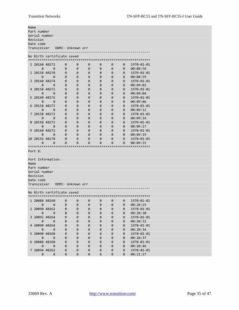
Name Part number Serial number Revision Date code Transceiver DDMI: Unknown err --------------------------------------------------------------- No Birth certificate saved *************************************************************** 1 20160 40272 0 0 0 0 0 0 1970-01-01 0 0 0 0 0 0 0 0 00:08:56 2 20158 40270 0 0 0 0 0 0 1970-01-01 0 0 0 0 0 0 0 0 00:08:59 3 20160 40274 0 0 0 0 0 0 1970-01-01 0 0 0 0 0 0 0 0 00:09:02 4 20158 40272 0 0 0 0 0 0 1970-01-01 0 0 0 0 0 0 0 0 00:09:04 5 20160 40276 0 0 0 0 0 0 1970-01-01 0 0 0 0 0 0 0 0 00:09:06 6 20158 40272 0 0 0 0 0 0 1970-01-01 0 0 0 0 0 0 0 0 00:09:12 7 20158 40272 0 0 0 0 0 0 1970-01-01 0 0 0 0 0 0 0 0 00:09:14 8 20158 40272 0 0 0 0 0 0 1970-01-01 0 0 0 0 0 0 0 0 00:09:17 9 20160 40272 0 0 0 0 0 0 1970-01-01 0 0 0 0 0 0 0 0 00:09:19 10 20156 40270 0 0 0 0 0 0 1970-01-01 0 0 0 0 0 0 0 0 00:09:25 *************************************************************** Port 8: Port Information: Name Part number Serial number Revision Date code Transceiver DDMI: Unknown err --------------------------------------------------------------- No Birth certificate saved *************************************************************** 1 20088 40260 0 0 0 0 0 0 1970-01-01 0 0 0 0 0 0 0 0 00:20:25 2 20090 40262 0 0 0 0 0 0 1970-01-01 0 0 0 0 0 0 0 0 00:20:30 3 20092 40264 0 0 0 0 0 0 1970-01-01 0 0 0 0 0 0 0 0 00:20:32 4 20090 40264 0 0 0 0 0 0 1970-01-01 0 0 0 0 0 0 0 0 00:20:34 5 20090 40260 0 0 0 0 0 0 1970-01-01 0 0 0 0 0 0 0 0 00:20:37 6 20088 40260 0 0 0 0 0 0 1970-01-01 0 0 0 0 0 0 0 0 00:20:46 7 20094 40262 0 0 0 0 0 0 1970-01-01 0 0 0 0 0 0 0 0 00:21:27
Transition Networks TN-SFP-BC55 and TN-SFP-BC55-I User Guide
33669 Rev. A http://www.transition.com/ Page 36 of 47
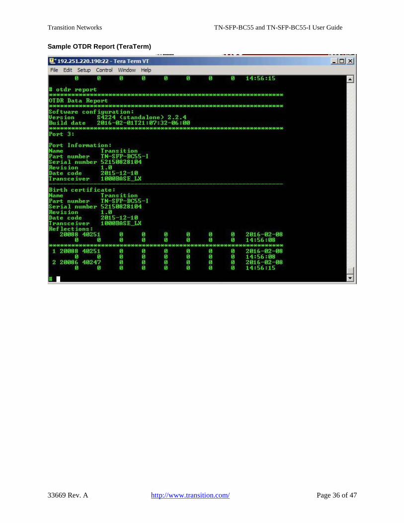
Sample OTDR Report (TeraTerm)
Transition Networks TN-SFP-BC55 and TN-SFP-BC55-I User Guide
33669 Rev. A http://www.transition.com/ Page 37 of 47
Sample OTDR Report (WordPad)
Transition Networks TN-SFP-BC55 and TN-SFP-BC55-I User Guide
33669 Rev. A http://www.transition.com/ Page 38 of 47
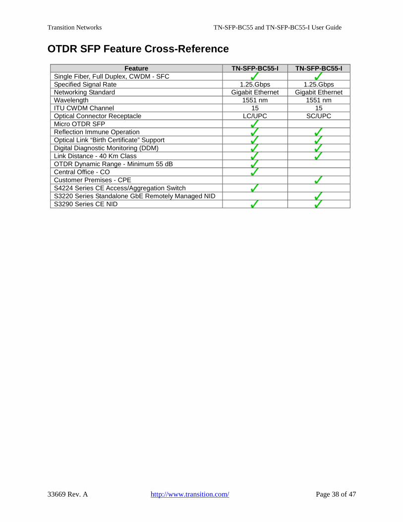
OTDR SFP Feature Cross-Reference
Feature TN-SFP-BC55-I TN-SFP-BC55-I Single Fiber, Full Duplex, CWDM - SFC Specified Signal Rate 1.25.Gbps 1.25.Gbps Networking Standard Gigabit Ethernet Gigabit Ethernet Wavelength 1551 nm 1551 nm ITU CWDM Channel 15 15 Optical Connector Receptacle LC/UPC SC/UPC Micro OTDR SFP Reflection Immune Operation Optical Link “Birth Certificate” Support Digital Diagnostic Monitoring (DDM) Link Distance - 40 Km Class OTDR Dynamic Range - Minimum 55 dB Central Office - CO Customer Premises - CPE S4224 Series CE Access/Aggregation Switch S3220 Series Standalone GbE Remotely Managed NID S3290 Series CE NID
Transition Networks TN-SFP-BC55 and TN-SFP-BC55-I User Guide
33669 Rev. A http://www.transition.com/ Page 39 of 47
Troubleshooting
Cleaning Instructions for the OTDR SFP and Fiber If any errored reflections or inaccurate reflections are recognized this should be the first step in the troubleshooting process. Inspect and clean both connectors in pairs.
It is important that every fiber connector be inspected and cleaned prior to mating.
Numerous tools and cleaning products are available for cleaning with a fiber cleaner for the fiber head as well as for cleaning with a ferrule cleaner. Cleaning products can include cartridge and pocket style cleaners, lint−free wipes, lint−free swabs, lint−free wet wipes, lint−free swabs, manual advance cleaners, etc. from a wide array of vendors.
This section is provided as a general guideline and not as a complete process or procedure, as no known cleaning method is 100% effective. Dirt is the single biggest problem with fiber optics. Inspect and clean connectors. Inspect and clean again until they are perfect. Inspect and clean both ends in pairs. Clean the connectors, the mating adapters, and the transceiver ports. Have a cleaning policy in place including a checklist of items tailored to your specific site requirements. Keep records for future troubleshooting (e.g., where cable is run, splice and termination locations, make and model of components, OTDR data, cleaning performed, etc.).
Follow industry safety precautions! Warning: Invisible laser radiation might be emitted from disconnected fibers or connectors. Do not stare into beams directly or view with optical instruments. Always turn off any laser sources before you inspect fiber connectors, optical components, or bulkheads. Always make sure that the cable is disconnected at both ends or that pluggable transceiver is removed from the device. Always wear the appropriate safety glasses when required for your area. Never look into a fiber with the device lasers on. Always follow proper proper grounding procedures. Never connect a fiber to a fiberscope with the device lasers on. See the FOA video Visual Inspection of Fiber Optic Connectors Using A Microscope at https://www.youtube.com/watch?v=IyumH8CiUPQ&feature=youtube. 1. Inspect the endface with a fiberscope.
a. If the endface is clean, plug it into a clean mating connector. b. If the endface is not clean, dry clean it.
2. Inspect the endface with a fiberscope. a. If the endface is clean, plug it into a clean mating connector. b. If the endface is not clean, dry clean it.
3. Inspect the endface with a fiberscope. a. If the endface is clean, plug it into a clean mating connector. b. If the endface is not clean, wet clean it and then immediately dry clean it.
4. Inspect the endface with a fiberscope. a. If the endface is clean, plug it into a clean mating connector.
Notes:
□ Before wet cleaning, make sure it does not leave a residue on the endface to avoid equipment damage. Wet cleaning is not recommended for bulkheads and receptacles as equipment damage can occur.
□ Follow the directions that came with the tools and cleaning products. □ Always keep a clean protective cap on unplugged fiber connectors and store unused protective
caps in a resealable container to prevent contamination. □ Always discard used cleaning amterials properly.
Transition Networks TN-SFP-BC55 and TN-SFP-BC55-I User Guide
33669 Rev. A http://www.transition.com/ Page 40 of 47
Error Messages and Recovery Procedures Message: Current cable length is x um with d reflections Reflection n is at xum (readrefl=x) Reflection saved in capture x Meaning: The command was successful. Recovery: No action required.
Message: Failed to get DDMI configuration. Failed to set DDMI configuration. Failed to read transceiver ID for port x Failed to read current cable length for port x Failed to capture reflections
Meaning: The DDMI OTDR command failed. Recovery: 1. Verify the SFP is a TN-SFP-BC55 or TN-SFP-BC55-I. 2. Verify that DDMI OTDR is enabled. 3. Make sure the optical fiber connections are clean. 4. Contact TN Support.
Message: Invalid port number Invalid capture number No OTDR Ports found Not OTDR Capable OTDR test failed capture contains no reflection data iport x a2 read fail, first fail occurs at x-th times Read a2 for port x re-enabled DDMI.
Meaning: The DDMI OTDR command failed. Recovery: 1. Verify the correct port number or capture number was entered. 2. Verify the device / port is OTDR capable. 3. Make sure the optical fiber connections are clean. 4. Re-try the capture operation. 5. Contact TN Support.
Message: Transceiver in port x is not supported Meaning: The SFP transceiver in port x is not supported. Recovery: 1. Verify the SFP is a TN-SFP-BC55 or TN-SFP-BC55-I. 2. Verify that DDMI OTDR is enabled. 3. Make sure the optical fiber connections are clean. 4. Contact TN Support. Message: DDMI is enabled, disabling now. DDMI is disabled. Meaning: Informational message. Recovery: None.
Transition Networks TN-SFP-BC55 and TN-SFP-BC55-I User Guide
33669 Rev. A http://www.transition.com/ Page 41 of 47
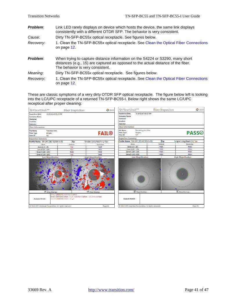
Problem: Link LED rarely displays on device which hosts the device, the same link displays consistently with a different OTDR SFP. The behavior is very consistent. Cause: Dirty TN-SFP-BC55x optical receptacle. See figures below. Recovery: 1. Clean the TN-SFP-BC55x optical receptacle. See Clean the Optical Fiber Connections on page 12.
Problem: When trying to capture distance information on the S4224 or S3290, many short distances (e.g., 15) are captured as opposed to the actual distance of the fiber. The behavior is very consistent. Meaning: Dirty TN-SFP-BC55x optical receptacle. See figures below. Recovery: 1. Clean the TN-SFP-BC55x optical receptacle. See Clean the Optical Fiber Connections on page 12.
These are classic symptoms of a very dirty OTDR SFP optical receptacle. The figure below left is looking into the LC/UPC receptacle of a returned TN-SFP-BC55-I. Below right shows the same LC/UPC receptical after proper cleaning:

Transition Networks TN-SFP-BC55 and TN-SFP-BC55-I User Guide
33669 Rev. A http://www.transition.com/ Page 42 of 47
General Troubleshooting Document the fiber optic network. Good documentation is invaluable in upgrading, troubleshooting or restoring a network. See http://www.thefoa.org/user/index.html.
Many factors can affect OTDR test accuracy. Variations in fiber optic cable structures affect accuracy. Differences between fiber types and manufacturing processes can contribute to differing OTDR results, as can physical issues like cable slack or aerial sag. Understanding that fiber length and cable length are not the same is also important when trying to locate a fault or break.
Fiber that gets rerouted after installation may be subject to macrobends caused by the fiber being moved and then bent. Tie wraps that are too tight can also cause macrobends. Dirty or damaged connectors and poor splices can cause loss in a fiber link, as can bad connectors, kinks in a cable, counterfeit cable, improper pulling techniques, preparation for or actual splicing or termination, bad processes or damage after termination, or fiber break in the back of the connector.
1. Determine if the problem is with one or all the fibers in the cable. 2. For high loss fibers, start with microscope inspection of terminations for proper polish, dirt, scratches
or damage. 3. Check the design specifications and installation documentation. 4. Interview the installer to discover processes that may lead to issues in installation, such as pulling
methods, lubrication, intermediate pulls, splicing or termination methods. 5. Check for patchcord problems (connector problems, caused by damage due to handling or numerous
matings). Note: after completing tests, troubleshooting and repairs, update documentation to reflect procedure changes and any changes to the network. If the fix is to switch to spare fibers and suspect fibers are not fixed, note that on documentation to prevent future problems.
See http://www.thefoa.org/user/index.html for more troubleshooting information.
Transition Networks TN-SFP-BC55 and TN-SFP-BC55-I User Guide
33669 Rev. A http://www.transition.com/ Page 43 of 47
Troubleshooting Procedures 1. Clean the connections; see Clean the Optical Fiber Connections on page 12. 2. Verify the SFP application; see “Applications” on page 9. 3. Verify proper SFP installation; see “SFP Installation” on page 14. 4. Verify the SFP Installation Cautions (e.g., clean the optics, etc.); see Cautions on page 14. 5. Make sure your site meets the Prerequisites and Restrictions on page 16. 6. Verify the SFP configuration. See Configuration via Web Interface on page 16 or Configuration via
CLI on page 21. 7. Verify the related S3290-xx or S4224 device firmware version. Upgrade the S3290-xx or S4224
device firmware if required. See the related Release Notes for firmware upgrade procedures. 8. Verify the related S3290-xx or S4224 device configuration. See “Related Manuals” on page 8. 9. Perform the basic S3290 or S4224 troubleshooting procedures. Refer to the related device’s Install
Guide. 10. If the default timestamp with the year 1970 or 1999 displays, indicating the NTP time server was not
active at device power up, configure an NTP time server. See NTP Server on page 16. 11. Verify that the optical fiber type (manufacturer and specs) matches the SFP calibration. Record your
model and System Information and then contact Transition Networks Tech Support.
For More Information Technical information in this document is subject to change without notice. For more information see the TN SFP Line Card or the SFP/XFP Landing page. The Fiber Optic Association, Inc. provides a Technical Bulletin on “Guidelines For Testing And Troubleshooting Fiber Optic Installations” at http://www.thefoa.org/tech/guides/TT3.pdf. There are other FOA Technical Bulletins that should be used as references for the design and planning of the network. These documents can be downloaded from the FOA Tech Topics website. Related Links
ANSI/TIA/EIA-568-B.3 - TIA/EIA STANDARD for Optical Fiber Cabling Components at http://www.csd.uoc.gr/~hy435/material/TIA-EIA-568-B.3.pdf
American National Standards Institute (ANSI) at www.ansi.org
Canadian Standards Association International (CSA) at www.csa-international.org
The Institute of Electrical and Electronic Engineers, Inc (IEEE) at www.ieee.org
National Electrical Manufacturers Association (NEMA) at www.nema.org
Society of Cable Telecommunications Engineers at www.scte.org
Telcordia Technologies (formerly Bellcore) at www.telcordia.com
Underwriters Laboratories, Inc. (UL) at www.ul.com

Transition Networks TN-SFP-BC55 and TN-SFP-BC55-I User Guide
33669 Rev. A http://www.transition.com/ Page 44 of 47
Record Model and System Information After performing the troubleshooting procedures above, and before calling or emailing Tech Support, record as much information as possible in order to help the Tech Support Specialist.
Model #: _____________________________ Serial #: _____________________________ ________
Your Transition Networks service contract #: ______________________________________________
Describe the problem: ________________________________________________________________ __________________________________________________________________________________ __________________________________________________________________________________ __________________________________________________________________________________ Describe any action(s) already taken to resolve the problem (e.g., changing mode, resetting, etc.): __________________________________________________________________________________ __________________________________________________________________________________ __________________________________________________________________________________
The model # and serial # of all other Transition Networks products in the network: _________________ __________________________________________________________________________________ __________________________________________________________________________________
Describe your network environment (layout, cable type, cable distance, etc.): ____________________ __________________________________________________________________________________ _________________________________________________________________________________ Transition Networks device history (have you returned the device before, is this a recurring problem, etc.): _________________________________________________________________________________ _________________________________________________________________________________ _________________________________________________________________________________
Any previous Return Material Authorization (RMA) numbers: _________________________________ _________________________________________________________________________________
List TN or third party equipment in the network: ____________________________________________ __________________________________________________________________________________ __________________________________________________________________________________
Describe SMF Optical Fiber Type and Manufacturer (e.g., commonly Corning SMF-28 optical fiber, or a different optical fiber, e.g. Sumitomo): ___________________________________________________ _________________________________________________________________________________ _________________________________________________________________________________
Other network, deployment, or operating environment requirements or issues out of the ordinary (e.g., vibrations, tropical humidity, elevations above 5,000M, any special / national conditions, fiber curl, temperature dependence, temp - humidity cycling, water immersion, damp heat, UV light, corrosion, fungus conditions, etc.): ______________________________________________________________ __________________________________________________________________________________ __________________________________________________________________________________ __________________________________________________________________________________ __________________________________________________________________________________ When and how was the last optical fiber cleaning performed? _________________________________ __________________________________________________________________________________

Transition Networks TN-SFP-BC55 and TN-SFP-BC55-I User Guide
33669 Rev. A http://www.transition.com/ Page 45 of 47
Contact Us Technical Support Technical support is available 24-hours a day:
US and Canada: 1-800-260-1312 International: 00-1-952-941-7600
Transition Now Chat live via the Web with Transition Networks Technical Support. Log onto www.transition.com and click the Transition Now link.
Web-based Seminars Log onto www.transition.com and click the Learning Center link.
E-Mail Ask a question by sending an e-mail to our tech support staff at [email protected] .
Address Transition Networks 10900 Red Circle Drive Minnetonka, MN 55343, U.S.A. Telephone: 952-941-7600 Toll free: 800-526-9267 Fax: 952-941-2322
Compliance Information Class I Laser Compliance This product has been tested and found to comply with the limits for FDA Class I laser for IEC60825, EN60825, and 21CFR1040 specifications.
Translated Safety Warnings Warning Class I laser product. Advarsel Laserprodukt av klasse I. Waarschuwing Klasse-I laser produkt. Aviso Produto laser de classe I. Varoitus Luokan I lasertuote. ¡Advertencia! Producto láser Clase I. Attention Produit laser de classe I Varning! Laserprodukt av klass I. Warnung Laserprodukt der Klasse I. Aviso Produto a laser de classe I. Avvertenza Prodotto laser di Classe I. Advarsel Klasse I laserprodukt.
FCC Regulations This equipment has been tested and found to comply with the limits for a Class A digital device, pursuant to Part 15 of the FCC rules. These limits are designed to provide reasonable protection against harmful interference when the equipment is operated in a commercial environment. This equipment generates, uses and can radiate radio frequency energy and, if not installed and used in accordance with the instruction manual, may cause harmful interference to radio communications. Operation of this equipment in a residential area is likely to cause harmful interference, in which case the user will be required to correct the interference at the user's own expense.
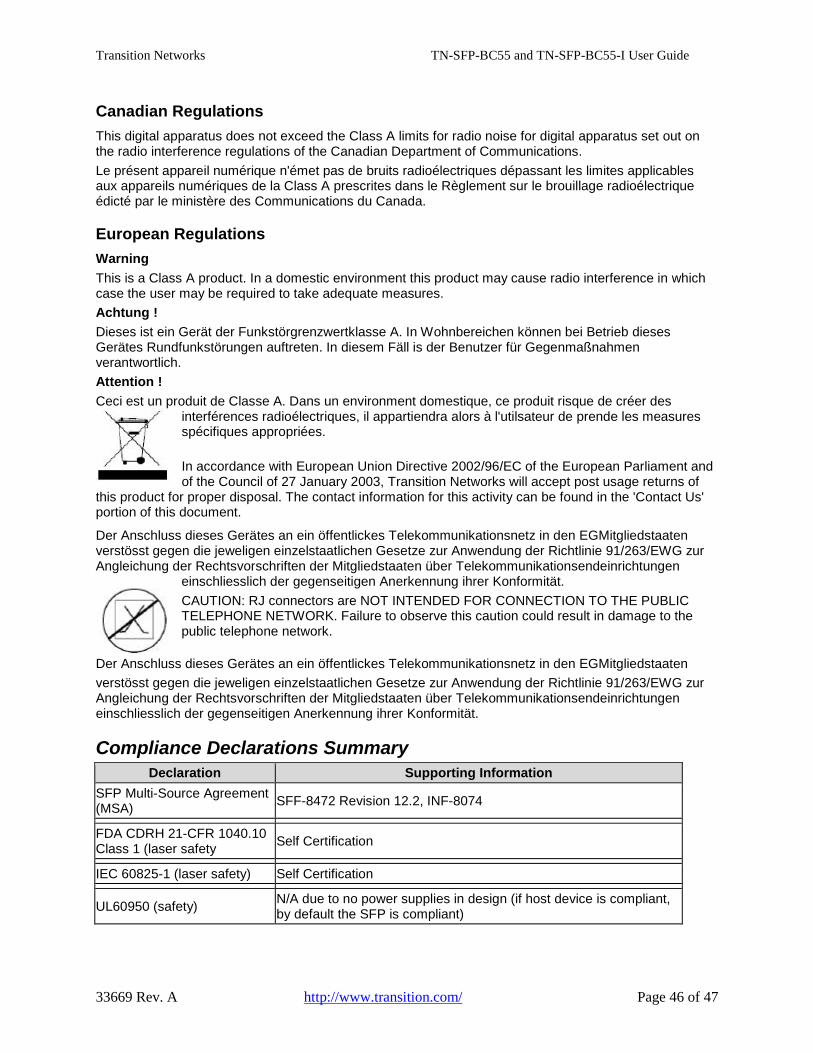
Transition Networks TN-SFP-BC55 and TN-SFP-BC55-I User Guide
33669 Rev. A http://www.transition.com/ Page 46 of 47
Canadian Regulations This digital apparatus does not exceed the Class A limits for radio noise for digital apparatus set out on the radio interference regulations of the Canadian Department of Communications. Le présent appareil numérique n'émet pas de bruits radioélectriques dépassant les limites applicables aux appareils numériques de la Class A prescrites dans le Règlement sur le brouillage radioélectrique édicté par le ministère des Communications du Canada.
European Regulations Warning This is a Class A product. In a domestic environment this product may cause radio interference in which case the user may be required to take adequate measures. Achtung ! Dieses ist ein Gerät der Funkstörgrenzwertklasse A. In Wohnbereichen können bei Betrieb dieses Gerätes Rundfunkstörungen auftreten. In diesem Fäll is der Benutzer für Gegenmaßnahmen verantwortlich. Attention ! Ceci est un produit de Classe A. Dans un environment domestique, ce produit risque de créer des
interférences radioélectriques, il appartiendra alors à l'utilsateur de prende les measures spécifiques appropriées. In accordance with European Union Directive 2002/96/EC of the European Parliament and of the Council of 27 January 2003, Transition Networks will accept post usage returns of
this product for proper disposal. The contact information for this activity can be found in the 'Contact Us' portion of this document.
Der Anschluss dieses Gerätes an ein öffentlickes Telekommunikationsnetz in den EGMitgliedstaaten verstösst gegen die jeweligen einzelstaatlichen Gesetze zur Anwendung der Richtlinie 91/263/EWG zur Angleichung der Rechtsvorschriften der Mitgliedstaaten über Telekommunikationsendeinrichtungen
einschliesslich der gegenseitigen Anerkennung ihrer Konformität. CAUTION: RJ connectors are NOT INTENDED FOR CONNECTION TO THE PUBLIC TELEPHONE NETWORK. Failure to observe this caution could result in damage to the public telephone network.
Der Anschluss dieses Gerätes an ein öffentlickes Telekommunikationsnetz in den EGMitgliedstaaten verstösst gegen die jeweligen einzelstaatlichen Gesetze zur Anwendung der Richtlinie 91/263/EWG zur Angleichung der Rechtsvorschriften der Mitgliedstaaten über Telekommunikationsendeinrichtungen einschliesslich der gegenseitigen Anerkennung ihrer Konformität.
Compliance Declarations Summary Declaration Supporting Information
SFP Multi-Source Agreement (MSA) SFF-8472 Revision 12.2, INF-8074
FDA CDRH 21-CFR 1040.10 Class 1 (laser safety Self Certification
IEC 60825-1 (laser safety) Self Certification UL60950 (safety) N/A due to no power supplies in design (if host device is compliant,
by default the SFP is compliant)

Transition Networks TN-SFP-BC55 and TN-SFP-BC55-I User Guide
33669 Rev. A http://www.transition.com/ Page 47 of 47
Record of Revisions
Rev Date Notes A 3/30/16 Initial production release for TN-SFP-BC55-I and TN-SFP-BC55 at v x114.
Trademarks: All trademarks and registered trademarks are the property of their respective owners.
Some information "Reproduced from the Fiber Optic Association Online Reference Guide. www.thefoa.org". Copyright restrictions: © 2016 Transition Networks. All rights reserved. No part of this work may be reproduced or used in any form or by any means - graphic, electronic or mechanical - without written permission from Transition Networks.