user guide motorized valve controllermotorized valve drive status the drive status of the motorized...
TRANSCRIPT

Motorized Valve Controller
V100
User GuideIM/V100_6

Electrical Safety
This equipment complies with the requirements of CEI/IEC 61010-1:2001-2 "SafetyRequirements for Electrical Equipment for Measurement, Control and Laboratory Use". Ifthe equipment is used in a manner NOT specified by the Company, the protection providedby the equipment may be impaired.
Symbols
One or more of the following symbols may appear on the instrument labelling:
Health and Safety
To ensure that our products are safe and without risk to health, the following pointsmust be noted:
1. The relevant sections of these instructions must be read carefully beforeproceeding.
2. Warning labels on containers and packages must be observed.
3. Installation, operation, maintenance and servicing must only be carried out bysuitably trained personnel and in accordance with the information given.
4. Normal safety precautions must be taken to avoid the possibility of an accidentoccurring when operating in conditions of high pressure and/or temperature.
5. Chemicals must be stored away from heat, protected from temperature extremesand powders kept dry. Normal safe handling procedures must be used.
6. When disposing of chemicals ensure that no two chemicals are mixed.
Safety advice concerning the use of the equipment described in this manual or anyrelevant hazard data sheets (where applicable) may be obtained from the Companyaddress on the back cover, together with servicing and spares information.
Information in this manual is intended only to assist our customers in the efficient operationof our equipment. Use of this manual for any other purpose is specifically prohibited and itscontents are not to be reproduced in full or part without prior approval of the TechnicalPublications Department.
Warning – Refer to the manualfor instructions
Caution – Risk of electric shock
Protective earth (ground) terminal
Earth (ground) terminal
Direct current supply only
Alternating current supply only
Both direct and alternatingcurrent supply
The equipment is protectedthrough double insulation

1
Symbol Identification and Section Contents
GETTING STARTED
This manual is divided into 5 sections which contain all the information needed toinstall, configure, commission and operate the COMMANDER V100. Each sectionis identified clearly by a symbol as shown below.
Displays and Function Keys• Displays and function keys• LED Indication• Error Messages
Operator Mode (Level 1)• Operator menus for:
– Standard controller– Remote Set Point controller– Profile controller– Multiple Fixed Set Points controller
Set Up Mode (Levels 2, 3 and 4)• Level 2 – Tuning• Level 3 – Set Points• Level 4 – Profile
Configuration Mode (Levels 5 and 6)• Level 5 – Basic hardware and control
functions• Level 6 – Ranges and passwords
Installation• Siting• Mounting• Electrical connections
8

2
CONTENTS
Information.The fold-out page inside on the back cover of thismanual shows all the frames in the programminglevels. Space is provided on the page for writing theprogrammed setting or selection for each frame.
1 DISPLAYS AND FUNCTION KEYS .............................................................. 31.1 Introduction ............................................................................................ 31.2 Use of Function Keys ............................................................................ 41.3 LED Alarms and Indicators .................................................................... 51.4 Error Messages ..................................................................................... 6
2 OPERATOR MODE ....................................................................................... 72.1 Introduction ............................................................................................ 72.2 Standard Controller ............................................................................... 82.3 Remote Set Point Controller ............................................................... 102.4 Profile Controller .................................................................................. 122.5 Multiple Fixed Set Points Controller .................................................... 14
3 SET UP MODE ............................................................................................ 163.1 Introduction .......................................................................................... 163.2 Motorized Valve Control ...................................................................... 173.3 Tuning (Level 2) ................................................................................... 193.4 Set Points (Level 3) ............................................................................. 203.5 Profile (Level 4) .................................................................................... 23
4 CONFIGURATION MODE .......................................................................... 264.1 Introduction .......................................................................................... 264.2 Accessing the Configuration Mode ..................................................... 264.3 Basic Hardware and Configuration (Level 5) ...................................... 284.4 Ranges and Passwords (Level 6) ....................................................... 38
5 INSTALLATION .......................................................................................... 415.1 Siting .................................................................................................... 415.2 Mounting .............................................................................................. 435.3 Electrical Connections ......................................................................... 455.4 Relays, Arc Suppression, Inputs and Outputs .................................... 45

3
1 DISPLAYS AND FUNCTION KEYS
Fig. 1.1 Front Panel Displays, Function Keys and Indicators
1.1 Introduction – Fig. 1.1The COMMANDER V100 front panel displays, function keys and LED indicatorsare shown in Fig. 1.1.
Function Keys
Raise
Lower
Auto/Manual
Parameter Advance
8888MRA1 A2
OP1
Alarm LEDs
Upper Display
Lower Display
Remote Set Point LED
Output Valve stateLED (secret-til-lit)
Manual Control LED
8888

4
…1 DISPLAYS AND FUNCTION KEYS
Fig. 1.2 Use of Function Keys
1.2 Use of Function Keys – Fig. 1.2
A – Raise and Lower Keys
LEV1OPEr
LEV2tUnE
B – Parameter Advance Key
LEV2tUnE
Pb100.0
Frame 2
bIAS 50.0 51.0
49.0
+
–
C – Auto/Manual Key
Use to change/set a parameter value… …move between levelsand…
125.2OPEN
125.2125.8
M
Auto
M
ManualIlluminated
Motorized ValveDrive Status
Process Variable
Control Set Point
Process Variable
Use to select Auto or Manual control mode
Frame 1(top of level)
Use to advance to the nextframe within a level…
Press and hold
…select the top (LEVEL) framefrom within a level
Note. This key also stores any changes made in the previous frame
LEVx100110021003
and…
OPENStOPCLSE

5
Fig. 1.3 LED Alarms and Indicators
1.3 LED Alarms and Indicators
LED Status
All • All LED's flashing – controller is in the configuration mode.
A1 • Flashes when Alarm 1 is active (off when inactive).
A2 • Flashes when Alarm 2 is active (off when inactive).
R • On when the controller is operating on the remote set point value.
• Off when the controller is operating using the local set pointvalue or one of the four fixed set points (in multiple set point mode).
• Flashes when a Ramp/Soak profile is running.
M • On when the controller is operating in Manual control mode.
• Off when the controller is operating in Auto control mode.
OPI • Secret-til-lit LED indicates when the output valve state isdisplayed in the lower display.
1 DISPLAYS AND FUNCTION KEYS…
MRA1 A2
OP1
A1
R
OP1
M
A2
6
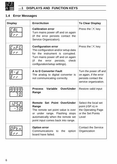
…1 DISPLAYS AND FUNCTION KEYS
Display Error/Action
Calibration errorTurn mains power off and on again(if the error persists contact theService Organization).
Configuration errorThe configuration and/or setup datafor the instrument is corrupted.Turn mains power off and on again(if the error persists, checkconfiguration/setup settings).
A to D Converter FaultThe analog to digital converter isnot communicating correctly.
Process Variable Over/UnderRange
Remote Set Point Over/UnderRangeThe remote set point value is overor under range. Flashing stopsautomatically when the remote setpoint input comes back into range.
Option errorCommunications to the optionboard have failed.
To Clear Display
Press the key
Press the key
Turn the power off andon again, if the errorpersists contact theservice organization.
Restore valid input
Select the local setpoint (rSP.n) inthe Operating Pageor the Set PointsLevel
Contact the ServiceOrganization
1.4 Error Messages
CALErr
CnFGErr
A-dErr
OPtnErr
9999 70
125.2 70

7
2 OPERATOR MODE
2.1 IntroductionOperator Mode (Level 1) is the normal day-to-day mode of the COMMANDER 100.Frames displayed in level 1 are determined by the control strategy which isselected during configuration of the instrument – see Section 4.
Note. Only the operating frames relevant to the configured strategy aredisplayed in Operator Mode.
The four control strategies are:
• Standard controller – page 8
• Remote Set Point controller – page 10
• Profile controller – page 12
• Multiple Fixed Set Points controller – page 14

8
2.2 Standard Controller
Process Variable Value
Control Set Point Value (Local set point)[Set point low limit to set point high limit]
Process Variable Value
Motorized Valve Drive StatusThe drive status of the motorized valve is displayed.OPEN – Valve is opening.StOP – Valve is stopped.CLSE – Valve is closing.
Continued on next page.
…2 OPERATOR MODE
•1 The Valve Drive Status is adjustable in Manual mode only.
Man
Auto
OPEN
OP1
125.2125.8
125.2
SPrP120.5
•1

9
Ramping Set Point Value (Read only)The actual set point value is displayed i.e. theinstantaneous value the controller is working to.
Security Code[0 to 9999]Select the appropriate security code to access:
Set Up mode (Levels 2, 3, 4).
Level 1 (Operator mode)Refer to Section 3 for levels 2, 3 and 4.
…2.2 Standard Controller
2 OPERATOR MODE…
•1 Not displayed if the ramping set point facility is turned off – refer to Section 3.4.
SPrP120.5
CodE 0
OPErLEV4PrFL
LEV1
LEV3SEtPtUnE
LEV2
•1

10
2.3 Remote Set Point Controller
…2 OPERATOR MODE
Process Variable Value
Control Set Point Value[Set point low to set point high limit]Adjustable in local Set Point Mode only.
Process Variable Value
Motorized Valve Drive StatusThe drive status of the motorized valve is displayed.OPEN – Valve is opening.StOP – Valve is stopped.CLSE – Valve is closing.
Remote Set Point SelectionrSPY – Remote Set PointrSPn – Local Set Point
Local or remote set point can also be selected usinga digital input.
The option to change the set point selection at thisframe can be disabled in the configuration level.
Remote Set Point Value (read only)
Continued on next page…
Note.If the remote set point input fails while selected, the controller selects the localset point value automatically. The upper display changes to rSP.F and thelower display flashes. When the fault condition is removed the remote set pointis re-selected automatically. To clear the error condition while the remote setpoint input is still outside its allowed range, select the local set point by pressingthe key (rSP.n is displayed).
•1 The Valve Drive Status is adjustable in Manual mode only.
Man
Auto 125.2125.8
OPEN
OP1
125.2
•1
rSPn123.4rSPn123.4
SPrP120.5

11
2 OPERATOR MODE…
…2.3 Remote Set Point Controller
•1 Not displayed if the ramping set point facility is turned off – refer to Section 3.4.
Ramping Set Point Value (Read only)The actual set point value is displayed i.e. theinstantaneous value the controller is working to.
Security Code
[0 to 9999]Select the appropriate security code to access:
Set Up mode (Levels 2, 3, 4).
Level 1 (Operator mode)See Section 3 for levels 2, 3 and 4.
CodE 0
SPrP120.5
•1
OPErLEV4PrFL
LEV1
LEV3SEtPtUnE
LEV2

12
…2 OPERATOR MODE
2.4 Profile Controller
Process Variable Value
Control Set Point Value[Set point low limit to set point high limit]
Process Variable Value
Motorized Valve Drive StatusThe drive status of the motorized valve is displayed.OPEN – Valve is opening.StOP – Valve is stopped.CLSE – Valve is closing.
Profile Segment Number (1 to 4) currently active
Profile Status
StOP – Profile inactive – the control set pointis equal to the local set point valuewhen the profile is not running.
run – Profile active – currently operating onthe segment indicated.
HOLD – Profile hold – pauses the current profileby putting it into 'Hold' mode. Theguaranteed ramp soak feature can alsobe used to put the profile into a 'Hold'mode until the process variable comesback within the hysteresis band.
Note. The profile status can be changed using adigital input.
Continued on next page…
•1 The Valve Drive Status is adjustable in Manual mode only.
Man
Auto 125.2125.8
OPEN
OP1
125.2
StoPSG 1
120.5SPrP
•1
SG 1HOLd
SG 1StoP
SG 1 run

13
…2.4 Profile Controller
2 OPERATOR MODE…
Ramping Set Point Value (Read only)The actual set point value is displayed i.e. theinstantaneous value the controller is working to.
Security Code[0 to 9999]Select the appropriate security code to access:
Set Up mode (Levels 2, 3, 4).
Level 1 (Operator mode)See Section 3 for levels 2, 3 and 4.
•1 Not displayed if the ramping set point facility is turned off – refer to Section 3.4.
CodE 0
SPrP120.5
•1
LEV4PrFL
LEV1
LEV3SEtPtUnE
LEV2OPEr

14
…2 OPERATOR MODE
2.5 Multiple Fixed Set Points ControllerIf the Multiple Fixed Set Points Controller type is selected during configuration, fourfixed control set points can be set – see Section 4.4.
Process Variable Value
Fixed Control Set Point Selected
Notes.a) The top display momentarily displays the set
point selected before reverting to the displayof the process variable value.
b) A digital input can also be used to select thefixed set points.
Process Variable Value
Motorized Valve Drive StatusThe drive status of the motorized valve is displayed.OPEN – Valve is opening.StOP – Valve is stopped.CLSE – Valve is closing.
Ramping Set Point Value (Read only)The actual set point value is displayed i.e. theinstantaneous value the controller is working to.
Continued on next page…
•1 The Valve Drive Status is adjustable in Manual mode only
•2 Not displayed if the ramping set point facility is turned off – refer to Section 3.4.
Man
Auto 125.2125.8
SP-1100.3
SP-4400.5
SP-2200.1
SP-3300.2
OPEN
OP1
125.2
•1
0
12.05SPrP
CodE
•2

15
2 OPERATOR MODE…
…2.5 Multiple Fixed Set Points Controller
Security Code[0 to 9999]Select the appropriate security code to access:
Set Up Mode (Levels 2, 3, 4).
Level 1 (Operator mode)See Section 3 for Levels 2, 3 and 4.
CodE 0
LEV4PrFL
LEV1
LEV3SEtPtUnE
LEV2OPEr

16
3 SET UP MODE
3.1 IntroductionTo access the Set Up Mode (Levels 2, 3 and 4) the correct password must beentered in the security code frame (the default password code is 0). Refer to thefold-out sheet at the back of this manual for the contents of these levels.
8
LEV1OPEr
CodE 0
LEV2tUnE
Correct Password
SEtPLEV3
Refer to the fold-out sheetfor the contents of each level

17
3 SET UP MODE… 83.2 Motorized Valve Control – Fig. 3.1The V100 is a 'boundless' process controller which provides an output that iseffectively the time derivative of the required regulator position, i.e. the controllersignals the regulator, not where to go to (position derivative), but in which directionto travel and how far to move, by a series of integral action pulses. Thus, thecontroller does not need to know the absolute regulator position and is unaffectedwhen regulator reaches the upper or lower limit, as determined by the regulator'slimit switches (giving rise to the term 'boundless').
When a deviation from set point is introduced the regulator is driven, for a length oftime equivalent to the proportional step. The regulator is then driven by integralaction pulses until the deviation is within the deadband setting.
Fig. 3.1 Boundless Control Action
ProportionalStep
TimeControlDeviation
Raise
Lower
Time
IntegralAction Pulses
ProportionalStep
ProportionalStep
IntegralAction Pulses
+
–

18
…3 SET UP MODE
3.2.1 Calculation for Control Pulses,Steps and Deviation (Boundless Control only)The following calculations, carried out by the instrument, are shown for guidancewhen setting deadband/travel time values. They can be used to check thesuitability of boundless control for a particular application.
Minimum 'ON' time of integral action pulses (for a fixed control deviation).
= Travel Time x Deadband %
% Proportional Band (in seconds)
Minimum (approximate) time between integral action pulses (for a fixed controldeviation)
= Integral Action Time x Deadband %
2 x % Control Deviation (in seconds)
Duration of the proportional step
= 2 x % Control Deviation% Proportional Band x Travel Time in Seconds
% Control Deviation = Set Point – Process Variable
Eng Hi – Eng Lox100
% Deadband = Deadband
Eng Hi – Eng Lox100
8

19
3 SET UP MODE…
3.3 Tuning (Level 2)
Level 2 – Tuning Level
Note. To select this frame from anywhere in thispage, press the key for a few seconds.
Proportional Band
Enter the proportional band value.[0.1% to 999.9%]
Integral Action Time[1 to 7200 seconds or OFF (OFF=0)]
Derivative Action Time[0.1 to 999.9 seconds or OFF (OFF=0)].
Motorized Valve Deadband
1 to 9999 [in engineering units].
Regulator Travel TimeTime taken for the regulator to travel from the fullyopen to the fully closed position.
[10 to 5000 seconds.]
8
1.0dr1U
30Intr
0.0d.bnd
1000r.trU
LEV2tUnE
100.0Pb
Set point Deadband(centred around set point)

20
…3 SET UP MODE
3.4 Set Points (Level 3)
Level 3 – Set Points Level
Note. To select this frame from anywhere in thispage, press the key for a few seconds.
Local Set Point Value[Within set point high and low limits, in engineeringunits]
Remote Set Point SelectionSet Point Type:
rSP.Y – remote set pointrSP.n – local set point
Remote set point value.
Alarm 1 Trip PointAlarm type:
A1.hP = High process alarmA1.LP = Low process alarmA1.hd = High deviation alarmA1.Ld = Low deviation alarm
Trip Point:Process & deviation alarms [in engineering units]
Continued on next page.
•1 Only displayed if the remote set point option is selected.
8
145.8rSP.n
LSPt125.8
800.0A1.hP
LEV3SEtP
270.0
•1
A1.HY

21
3 SET UP MODE…
Alarm 1 Hysteresis Value[in engineering units]
Alarm 2 Trip PointAlarm type:
A2.hP = High process alarmA2.LP = Low process alarmA2.hd = High deviation alarmA2.Ld = Low deviation alarm
Trip Point:Process & deviation alarms [in engineering units]
Alarm 2 Hysteresis Value[in engineering units]
Remote Set Point Input Ratio and BiasThe remote set point value =
ratio x remote set point input + bias.Ratio[0.001 to 9.999]
Bias[in engineering units]
Continued on next page.
…3.4 Set Points (Level 3)
•1 Only displayed if custom alarm hysteresis is selected – see section 4.3.2,
•2 Only displayed if the remote set point option is selected.
8
1.000rAt0
0.0bIAS
200.0A2.hP
r.rtE OFF
•2
•2
162.0A1.HY•1
18.5A2.HY•1

22
…3 SET UP MODE
…3.4 Set Points Level
Ramp Rate (for ramping set point facility)[1 to 9999 engineering units per hour, or OFF]
The ramping set point facility can be used to preventa large disturbance to the control output when the setpoint value is changed. This only applies to the localand multiple fixed set points.
Note. For remote set points, the ramp rate isapplicable only when switching from remote to local,not from local to remote.
Offset AdjustmentAn offset can be applied to the process variable inputto enable spot calibration or the removal of systemerrors.
[±10% of engineering range in engineering units]
8
r.rtE 0FF
O.AdJ 0.3
Actual (Ramping) Set Point Valueused by PID Algorithm*
0
100
200
300
1 Hour
Displayed Local Set Point Value
Time
PV
* e.g. Ramp Rate = 200 Increments/Hour

23
3 SET UP MODE…
3.5 Profile (Level 4)A four segment ramp/soak profile facility is provided. This level can only beaccessed if the profile option is selected in the configuration level. The foursegments are fixed as ramps or soaks as follows:
Level 4 – Profile Level
Note. To select to this frame from anywhere in thispage, press the key for a few seconds.
Start value for 1st Segment (ramp).[Within display range (in engineering units)]
Enter the start value required.
End Value for 1st Segment (ramp).[Within display range (in engineering units)]
Enter the end value required.
Continued on next page.
•1 With the self-seeking set point facility enabled, the first ramp starts at thecurrent process variable value instead of the start value for the 1st segment.
…8
200.0End.1
Str.1100.0
LEV4PrFL
10.0
•1
rtE.1
Set PointValue
1 2 3 4Time
rtE.1
SKt.2
rtE.3
SKt.2
End.3
End.1
Str.1

24
…3 SET UP MODE
…3.5 Profile (Level 4)
Ramp Rate for 1st Segment.[Engineering units* ]
Enter the ramp rate required.* The time option Eng Units/hr or Eng Units/min is
set in the configuration level – see section 4.3.2.
Soak Time for 2nd Segment.[0 to 999.9 minutes or hours]*
End Value for 3rd Segment (ramp).[Within display range (in engineering units)]
Ramp Rate for 3rd Segment.[Engineering units/hour or /minute]*
* Depending on the time option selected in theconfiguration level.
Continued on next page.
•1 The engineering value is shown with an extra decimal place (up to a maximumof 3) for greater accuracy in setting the ramp rate.
8
100.0End.3
20.00rtE.3
60.00SKt.2
40.00rtE.1•1
30.00SKt.4
0Time
Set PointValue
Example. Required Ramp Rate 40°C/minRamp Rate set to 40, Time Option set to 'Min' – see section 4.3.2
2 Min
801st Segment
40

25
3 SET UP MODE
…3.5 Profile (Level 4)
Soak Time for 4th Segment.[0 to 999.9 minutes or hours]** Depending on the time option selected in the
configuration level.
Self Seeking Set Point Enable.YES – enable self seeking set pointNO – disable self seeking set point
When enabled the controller inserts the currentprocess variable value as the starting point oninitiation of the profile (instead of the start value forsegment 1).
Profile Hysteresis for Guaranteed Ramp/Soak.[In engineering units or OFF = 0]
If the process variable deviates from the set point bymore than the value set, the program is suspendedbut continues automatically when the processvariable returns within the set limits. The hysteresisvalue applies above and below set point under allprogram conditions.
Number of Program Repeats[0 to 99 or infinite (InFt> 100]
•2 The engineering value is shown with an extra decimal place (up to a maximumof 3) for greater accuracy in setting the ramp rate.
8
YESS.S.S.P
OFFP.HYS
0rPtS
30.00SKt.4•2

26
4 CONFIGURATION MODE
Fig. 4.1 Accessing the Configuration Mode (Config/Normal Switch)
4.1 IntroductionThe Configuration Mode comprises two levels (5 and 6) as shown in Fig. 4.2.
Level 5 is divided into four frames. For most simple applications it is only necessaryto set up the parameters in the first frame.
Note.When in the configuration level:
• All the l.e.d. indicators flash.
• All relays and logic outputs are turned off.
• The analog output reverts to 0% (4mA) output level.
4.2 Accessing the Configuration Mode – Fig. 4.1To access the Configuration Mode set the security switch to the 'Configure' position(levels 1 to 4 cannot be accessed from this setting). When the configurationparameters are programmed, reset the security switch to the 'Normal' position andthe Operating page is displayed automatically .
Configure
Normal

27
4 CONFIGURATION MODE…
Fig. 4.2 Configuration Frames (Levels 5 and 6)
LEV5CnFG
AbCd----
EFGH----
JKLn----
PrSt----
LEV6CnFG
EnGH100.0
EnGL 0.0
rt.HI100.0
rt.LO 0.0
SP-H100.0
SP-L 0.0
SP-1 10.0
Hardware Assignment andInput Type
Alarms and Set PointTypes
Operator Access andControl Action
Digital Input andSerial Communications
SP-3 30.0
SP-4 40.0
C-OP 0
S.PAS 0
Addr 1
SP-2 20.0

28
…4 CONFIGURATION MODE
4.3 Basic Hardware and Configuration (Level 5)
4.3.1 Hardware Assignment and Input Type – Fig. 4.3
Level 5 –Configuration
Note. To select this frame from anywhere in thispage, press the key for a few seconds.
'ABCD' Settings
The parameter to be changed is indicated by theletter which is flashing. Parameter options are shownin Fig. 4.3.
A = Hardware configurationb = Input type and rangeC = Temperature unitsd = Process variable display decimal places
Notes.Note 1. When the input type (parameter b) ischanged, the range is set automatically to themaximum permissable for the input type selected.
Note 2. For custom settings contact the localdistributor.
Continued on page 30.
AbCd6400
AbCd6400
AbCd6400
AbCd6400
LEV5CnFG
----EFGH
29
4 CONFIGURATION MODE…
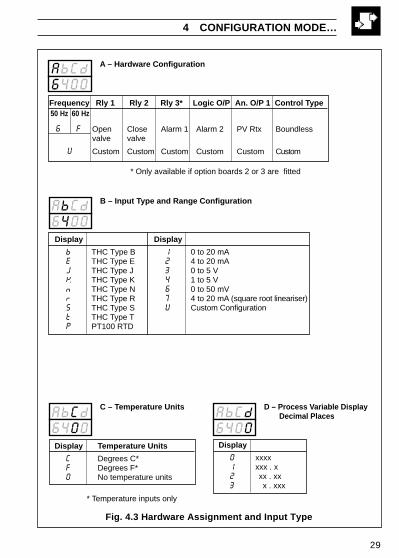
Fig. 4.3 Hardware Assignment and Input Type
Frequency Rly 1 Rly 2 Rly 3* Logic O/P An. O/P 1 Control Type
Open Close Alarm 1 Alarm 2 PV Rtx Boundless valve valve
Custom Custom Custom Custom Custom Custom
A – Hardware Configuration
B – Input Type and Range Configuration
D – Process Variable DisplayDecimal Places
6400AbCd
AbCd6400
AbCd6400
50 Hz 60 Hz
6 F
C – Temperature UnitsAbCd6400
U
* Only available if option boards 2 or 3 are fitted
* Temperature inputs only
Display
b THC Type BE THC Type EJ THC Type JK THC Type Kn THC Type Nr THC Type RS THC Type St THC Type TP PT100 RTD
Display
1 0 to 20 mA2 4 to 20 mA3 0 to 5 V4 1 to 5 V6 0 to 50 mV7 4 to 20 mA (square root lineariser)U Custom Configuration
Display
0 xxxx1 xxx . x2 xx . xx3 x . xxx
Display Temperature Units
C Degrees C*F Degrees F*0 No temperature units

30
…4 CONFIGURATION MODE
'EFGH' Settings
The parameter to be changed is indicated by theletter which is flashing. Parameter options areshown in Fig. 4.4.
E = Alarm 1 typeF = Alarm 2 typeG = Alarm HysteresisH = Set Point type
Note. For custom settings contact the localdistributor.
Continued on page 34.
4.3.2 Alarms and Set Point Types – Fig. 4.4
Note. All relays are de-energised in the alarm state.
EFGH3241
EFGH3241
EFGH3241
EFGH3241
----JKLn

31
Display
0 None1 High Process2 Low Process3 High Deviation4 Low Deviation
F – Alarm 2 Type*
Display
0 None1 0.1%2 0.2%3 0.5%4 1.0%5 2.0%6 5.0%U Custom
G – Alarm Hysteresis
Display
0 Local Set Point Only1 Local + Remote Set Point (no Remote Set Point Tracking)**2 Local + Remote Set Point (with Remote Set Point Tracking)**3 Multiple Fixed Set Points4 Ramp/Soak (Time Units in Minutes)5 Ramp/Soak (Time Units in Hours)
H – Set Point Type
Display
0 None1 High Process2 Low Process3 High Deviation4 Low Deviation
E – Alarm 1 Type*EFGH3241
EFGH3241
3241EFGH
EFGH3241
* Refer to Figs. 4.5 and 4.6 for alarm action
Value in % ofengineeringrange
**Only available if option board is fitted. Remote set point input is 4 to 20 mA
Value in engineering units – see Note 1
See Note 2
4 CONFIGURATION MODE…
Fig. 4.4 Alarms and Set Point Types
Note 1. When custom alarmhysteresis is selected, the alarmhysteresis values are setindividually in the set up level
– see section 3.3
Note 2. With remote set point tracking enabled the local set pointtracks the remote set point when in the remote set point mode.

32
…4 CONFIGURATION MODE
…4.3.2 Alarms and Set Point Types – Fig. 4.4
Note. All relays are de-energised in the alarm state.
Process and Deviation Alarms (High/Low) – Figs 4.5 and 4.6
Fig. 4.5 High and Low Process Alarm Action
Trip point
Alarm on
Alarm off
Alarm on
Alarm off
High Process
Low Process
Hysteresis
Hysteresis
ProcessVariable

33
4 CONFIGURATION MODE…
Fig. 4.6 High and Low Deviation Alarm Action
High Deviation+ve Trip Value
Hysteresis
Alarm on
Alarm off
Control SetPoint
Alarm on
Alarm off
PositiveTrip Value
NegativeTrip Value
High Deviation–ve Trip Value
Alarm on
Alarm offNegativeTrip Value
Positive Trip Value
Low Deviation Alarm
High Deviation Alarm
Control SetPoint
Hysteresis
HysteresisLow Deviation+ve Trip Value
Alarm on
Alarm off
HysteresisLow Deviation–ve Trip Value
ProcessVariable
ProcessVariable

34
…4 CONFIGURATION MODE
4.3.3 Operator Access and Control Action – Fig. 4.7
'JKLN' Settings
The parameter to be changed is indicated by theletter which is flashing. Parameter options are shownin Fig. 4.7.
J = Power recovery modeK = Operator selection enable – control functionsL = Operator selection enable – set point functionsn = Control action
Note. For custom settings contact the localdistributor.
Continued on page 36.
JKLn2110
JKLn2110
JKLn2110
JKLn2110
----PrSt

35
4 CONFIGURATION MODE…
Fig. 4.7 Operator Access and Control Action
2110
2110
JKLn
JKLn
JKLn2110Display Mode
0 Last Mode1 Manual with last Valve position2 Manual with Valve fully closed3 Manual with Valve fully open4 AutoU Custom
J – Power Recovery Mode
Display Auto/Manual
0 Enable Auto/Manual1 Disable Auto/Manual
K – Operator Selection EnableControl Functions
Display Local Set Point Adjustment and Local/Remote Set Point Selection
0 Enable Both Functions1 Disable Set Point Adjust, Enable Local/Remote Selection2 Enable Set Point Adjust, Disable Local Remote Function3 Disable Both Functions
L – Operator Selection Enable – Set Point Functions
Display Action
0 Reverse1 Direct
N – Control Action
2110JKLn

36
…4 CONFIGURATION MODE
4.3.4 Digital Input and Serial Communications – Fig. 4.8
'PRST' Settings
The parameter to be changed is indicated by theletter which is flashing. Parameter options are shownin Fig. 4.8.
P = Digital input functionr = Analog input digital filterS = Serial communications configurationt = Serial communication parity
Note. For custom settings contact the localdistributor.
Information. All digital input functions except 6 are triggered on the risingor falling edges to enable the front panel keys to change the functionwhen the digital input is operational.
Fig. 4.8 Digital Inputs
PrSt2100
PrSt2100
PrSt2100
PrSt2100
CnFGLEV5
Run
Hold
Remote
Local
Manual
Auto
Lock
Unlock
Select nextSet Point
Run
Stop
1 Auto/Manual
2 Local/Remote
4 Ramp/Soak Run-Hold
5 Ramp/Soak Run-Hold
6 Front Panel Lockout
7 Select Fixed Set Points

37
4 CONFIGURATION MODE…
Fig. 4.9 Digital Input and Serial Communications
Display
0 None1 Odd2 Even
Display Baud Rate, 2/4 Wire
0 Off1 2400, 2 Wire2 2400, 4 Wire3 9600, 2 Wire4 9600, 4 Wire
S – Serial CommunicationConfiguration
Display
0 0 seconds1 1 second2 2 seconds5 5 secondsA 10 secondsB 20 secondsC 40 secondsD 60 seconds
R – Analog Input Digital Filter
2100 2100PrSt PrSt
PrSt2100
Input filter averages the process
variable input values over the time set
PrSt2100Display Function
0 None1 Auto/Manual2 Local/Remote4 Ramp/Soak Run-Hold5 Ramp/Soak Run-Stop6 Front Panel Lockout7 Select Fixed Set Points
P – Digital Input Functions
T – Serial CommunicationsParity

38
…4 CONFIGURATION MODE
4.4 Ranges and Passwords (Level 6)
Ranges and Limits
Engineering (Display) Range
High Value[–999 to 9999]
Low Value[–999 to 9999]
Retransmission RangeThe retransmission range defines engineering rangeto be transmitted.
Retransmission High (20mA output)[–999 to 9999 (in engineering units)]
Retransmission Low (4mA output)[–999 to 9999 (in engineering units)]
Continued on next page…
•1 The engineering range high and low values are automatically set to themaximum allowed value when thermocouple or RTD is selected in theconfiguration level – see Section 4.3.1.
•2 Only displayed if the analog output is configured to retransmit the processvariable or control set point value.
0.0EnGL
EnGH100.0
LEV6CnFG
•1
100.0SP-H
100.0rt.HI
0.0rt.LO
•2
•2

39
4 CONFIGURATION MODE…
…4.4 Ranges and Passwords (Level 6)
Set Point LimitThe Set Point Limit defines limits within which thelocal set point can be adjusted (these limits alsoapply to remote set point).
High Limit[–999 to 9999]
Low Limit[–999 to 9999]
Fixed Set Point Values (1 to 4)Select the set point values required in the multiplefixed set point facility.
Fixed Set Point 1[–999 to 9999 (in engineering units)]
Fixed Set Point 4[–999 to 9999 (in engineering units)]
Continued on next page…
•1 This limit applies to the local and remote set point values.
•2 Only displayed if the multiple fixed set point facility is selected.
0.0SP-L
SP-H100.0
OPENC-OP
10.0SP-1
30.0SP-4
•1
•2
•1
•2

40
…4 CONFIGURATION MODE
…4.4 Ranges and Passwords (Level 6)
Configured OutputThis output value is used when:
a) manual control is selected using a digital input, orb) the process variable input fails.
OPEN – Opens the valve fully.CLSE – Closes the valve fully.LASt – Leaves the valve at its current
position.
Setup Password[0 to 9999 (default 0)]
This password enables access to the setup levels(levels 2, 3, and 4) and to the auto tune facility.
Modbus Address[1 to 99]
This frame allows the Modbus address to be set.
0S.PAS
1Addr
C-OPOPEN

41
Fig. 5.1 General Requirements
SensorClose to the Sensor
Avoid Vibration
At Eye Level
5 INSTALLATION
5.1 Siting – Figs. 5.1 and 5.2

42
…5 INSTALLATION
Fig. 5.2 Environmental Requirements
…5.1 Siting – Figs. 5.1 and 5.2
55°CMax.
0°CMin.
0 to 90% RH
+
IP65/NEMA3(front panel)
IP20(rear)
Temperature Limits
Environmental Limits
Humidity Limits
Use Screened Cable

43
5 INSTALLATION…
Fig. 5.3 Overall Dimensions
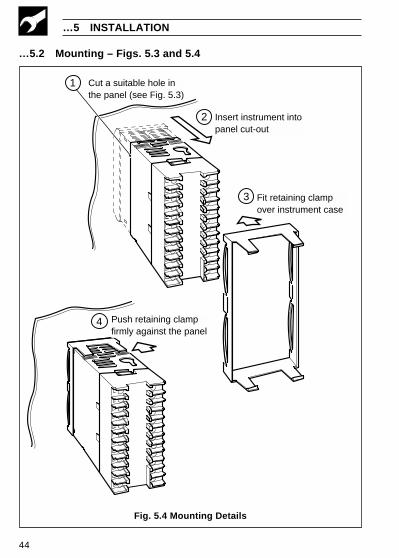
5.2 Mounting – Figs. 5.3 and 5.4The instrument is designed for panel mounting (see Fig. 5.4). Overall dimensionsare shown in Fig. 5.3.
3.54(91)
3.78(96)
1.57(40)
1.89(48)
0.58(14.7)
0.11 (2.7)
Dimensions in inches (mm)
Panelcut-out
4.68 (119)3.11(79)
3.62 + 0.03– 0
(92 )+ 0.8– 0
(45 )+ 0.6– 0
1.77 + 0.02– 0
≥ 0.55(14)
≥ 0.55 (14)
44
…5 INSTALLATION
…5.2 Mounting – Figs. 5.3 and 5.4
Fig. 5.4 Mounting Details
Cut a suitable hole inthe panel (see Fig. 5.3)
Insert instrument intopanel cut-out
Fit retaining clampover instrument case
Push retaining clampfirmly against the panel
1
2
3
4

45
EC Directive 89/336/EEC
In order to meet the requirementsof the EC Directive 89/336/EEC forEMC regulations, this product mustnot be used in a non-industrialenvironment.
5.3 Electrical Connections –Fig. 5.5 (overleaf)
Warning. Before making anyconnections, ensure that the powersupply, any poweredcontrol circuitsand high common mode voltagesare switched off.
Note. If it is not possible to avoidstrong electrical and magneticfields, screened cables withinearthed metal conduit must beused.
5.4 Relays, Arc Suppression,Inputs and Outputs
5.4.1 Relay Contact RatingsRelay contacts are rated at:
115/230V AC at 5A (non-inductive).
250V DC 25W max.
5.4.2 Arc SuppressionArc suppression components are fittedto relay outputs 2 and 3 only. The arcsuppression components suppliedmust be fitted to relay output 1.
5 INSTALLATION…
5.4.3 Logic Output18V DC at 20mA, minimum load900Ω.
Isolated from inputs (not fromanalog O/P),
dielectric strength 500V d.c. for 1minute.
5 . 4 . 4 R e t r a n s m i s s i o nAnalog Output
Max. load 15V (750Ω at 20mA).
Isolated from inputs (not from logicO/P),
dielectric strength 500V d.c. for 1minute.
5.4.5 Digital InputType: Volt-free
Minimum Pulse: 250ms

46
Note. The analog output and logic output use a common positiveterminal, capable of driving both outputs simultaneously.
Fig. 5.5 Electrical Connections
…5 INSTALLATION
AnalogOutput
–
+
THCmillivoltsand volts
RTD –
3rd lead
RTD +
3-leadRTD
–
+
Milliamps
1
2
3
4
–
+
*Milliamps
2-wiretransmitter
RTD –
RTD –
RTD +
2-lead RTDand resistance
C
Valve OpenRelay ***
+
– 1
2
3
4
5
6
7
8
9
10
11
12
13
14
15
16
17
18
19
20
21
22
23
24
–
+
–
L
N
N/C
C
N/O
Valve CloseRelay
N/C
C
N/O
AuxiliaryInput
(Remote Set Point)
DigitalInput
+
–
RS485TX
RS485RX
+
–
RS485
Rel
ay O
utpu
t 3
N/C
C
N/O
+
+
–
–
Analog Input(see below)
RTD1
Transmitter PSU+
+ LogicOutput– seeNote
**100Ω
* Using internal transmitter power supply** Use 100Ω shunt resistor provided with instrument*** Fit the arc suppression component provided with instrument
**100Ω
Tx
1 A fuse
24V d.c.–
+
85 to265V a.c.MainsSupply

8CUSTOMER SETUP LOGCustomer Support
We provide a comprehensive after salesservice via our Worldwide ServiceOrganization. Contact one of the followingoffices for details of your nearest Serviceand Repair Centre.
United KingdomABB LimitedTel: +44 (0)1480 475321Fax: +44 (0)1480 217948
United States of AmericaABB Inc.Tel: +1 215 674 6000Fax: +1 215 674 7183
Client Warranty
Prior to installation, the equipment referred to in this manual must be stored in a clean,dry environment, in accordance with the Company's published specification. Periodicchecks must be made on the equipment's condition.
In the event of a failure under warranty, the following documentation must be providedas substantiation:
1. A listing evidencing process operation and alarm logs at time of failure.
2. Copies of all storage, installation, operating and maintenance records relating to thealleged faulty unit.
LEV1OPEr
CodE 0
LEV2tUnE
Intr 30
LEV3SEtP
LSPt125.8
rsPn145.8
A1hP800.0
A2hP200.0
rAtO1.000
bIAS 0.0
rrtE OFF
OAdJ 0.3
LEV4PrFL
Str1100.0
End1200.0
rtE1 10.0
SKt2 60.0
End3100.0
rtE3 20.0
SKt4 30.0
SSSP YES
PHYS YES
rPt5 0
Company Standard settings areshown in the lower display
Instrument Serial Number:
V 1 0 0 /Product Code: /
drIV 1.0
Pb100.0
d.bnd 0.0
r.trV.1000

IM/V
100
Issu
e 6
The Company’s policy is one of continuous productimprovement and the right is reserved to modify the
information contained herein without notice.
Printed in UK (03.05)
© ABB 2005
ABB LimitedHoward Road, St. NeotsCambridegshirePE19 8EUUKTel: +44 (0)1480 475 321Fax:+44 (0)1480 217948
ABB Inc.125 E. County Line RoadWarminsterPA 18974USATel: +1 215 674 6000Fax:+1 215-674 7183
ABB has Sales & Customer Supportexpertise in over 100 countries worldwide
www.abb.com
CUSTOMER CONFIGURATION LOG
LEV5CnFG
AbCd----
EFGH----
JKLn----
PrSt----
LEV6CnFG
EnGH100.0
EnGL 0.0
SP-H100.0
SP-L 0.0
SP-1 10.0
SP-2 20.0
SP-3 30.0
SP-4 40.0
S.PAS 0
Addr 1
C-OPOPEN
Company Standard settings areshown in the lower display
rt.HI100.0
rt..LO 0.0