use of abaqus explicit for composite sandwich damage … · 2020-02-03 · curved composite...
TRANSCRIPT

2015 SIMULIA Community Conference 1 www.3ds.com/simulia
Use of Abaqus Explicit for Composite Sandwich Damage Prediction during Bird Impact
M. Al-Khalil, E. Kirtil, R. Rigby
Airbus
Abstract: A method development program of testing and simulations was carried out to develop
bird impact NLFEA capabilities of composite sandwich damage prediction and bird dispersion
after penetration of the primary layer using Abaqus Explicit. Curved composite honeycomb panels
(referred to as J-Nose) representing typical composite wing Fixed Leading Edge (FLE) structure
were subjected to bird strike to generate data for method validation. The test campaign was
tailored to produce various levels of damage and modes of failure; from minor localized core/skin
damage to panel perforation. In all tests high speed video were installed to capture the behavior
of the structure during the impact. In some tests, fully instrumented witness panel was installed to
enable measurement of deformation as a measure of bird residual energy and dispersion after
bird penetration of the sandwich panel. FE models were created of the tested structure and
analyzed using ABAQUS Explicit and the results were compared with tests. The analysis
performed used a standard Lagrangian bird model developed and validated at Airbus over many
years. In general, good correlation was obtained between tests and simulations results. It is known
that Lagrangian bird models suffer from numerical instability in case of impacting sharp edges
due to element distortion. To avoid such numerical difficulties, the SPH capability available in
Abaqus/Explicit was used to generate a representative SPH bird model. Test cases were re-
analyzed with the SPH bird model and results compared to the Lagrangian approach. A summary
of bird impact simulations and correlation against tests is presented in this paper.
Keywords: Aircraft, Wing, Leading, Edge, Bird, Damage, Impact, Composites, Sandwich
1. Introduction
Bird impact incidents on aircraft are not uncommon and they can cause structural and system
damage. Although measures have been implemented to prevent bird impacts from occurring, it is
impossible to prevent them totally. Further details regarding statistical reports related to bird
impact incidents can be found in [1-3]. All forward facing components of an aircraft are most
susceptible to bird strike such as leading edges of the wings and empennage, engine fan blades and
inlet, windshield, window frame, radome, landing gear and forward fuselage as illustrated in
Figure 1. The aviation authorities require that all aircraft structures in the vulnerable zones must
be designed to assure capability of continued safe flight and landing of the aircraft after bird
impact (EASA CS 25.631).

2 2015 SIMULIA Community Conference www.3ds.com/simulia
Figure 1 Illustration of aircraft components exposed to the risk of bird impact
Bird impact on aircraft structure is a complex phenomenon because of the high number of
variables involved. Such variables include material characteristics of the impacted structure and
bird behaviour and its interaction with the aircraft structure i.e. accurately predicting the level of
pressure/forces transmitted to the structure. Traditionally, aerospace manufacturers rely heavily on
tests, supported by empirical equations, for design and certification of aircraft subjected to bird
impact. Such methods are not only time-consuming and expensive but they could lead to
conservative design, resulting in weight penalty. In addition, such tests are subject to a degree of
uncertainty due to the lack of consistency in bird impact test results for the same bird strike test
configuration.
With the increase of finite element software tools capabilities and hardware computing power, it is
now becoming more realistic to use such tools to develop finite element methods for predicting the
behaviour of aircraft structures subjected to bird impact. However, it is important to emphasize
that the analysis/numerical techniques must be validated through correlation with tests on
sufficiently representative structure.
For almost two decades, Airbus has been involved in the development of bird strike
methodologies for aircraft structures, (mainly for metallic but more recently for composite) and

2015 SIMULIA Community Conference 3 www.3ds.com/simulia
works closely with other Aerospace partners. A typical example of bird strike simulation and
correlation with test on generic fixed leading structure, shown in Figure 2, was performed in
collaboration with SONACA Aerospace manufacturer.
Figure 2 Simulation (ABAQUS Explicit) and test of bird impact on generic fixed leading edge structure
Composite materials including sandwich construction are increasingly being used for aircraft
structures driven by high stiffness and strength to weight ratios. One of the main challenges of
using composite structure is their susceptibility to impact damage. Therefore, understanding their
behavior and in particular failure mechanisms is critical if the full benefit of using composites is to
be exploited.
Bird impact nonlinear finite element methodology development and validation for composite
sandwich J-Nose structure (situated in the wing leading structure) was performed using ABAQUS
Explicit. Tests were performed to generate data for correlation with simulations. The analysis
performed used a standard Lagrangian bird model developed and validated at Airbus. As part of
ongoing bird modelling enhancement, Smooth Particle Hydrodynamics (SPH) capability within
ABAQUS Explicit V613.3 was used and correlated with tests and Lagrangian approach. This
paper outline a summary of the work performed including bird impact simulations and correlation
with test results.
2. Method Validation
A bird strike test campaign was performed on a number of composite honeycomb panels,
representative of a typical composite Fixed Leading Edge structure referred to a J-Nose. The aim
of the test campaign was to provide test data for correlation with ABAQUS Explicit for method
validation in particular for a) material failure prediction and b) predictive capability for secondary
impact and dispersion after bird penetration of the J-Nose. It is important to note the impact
scenarios considered such as impact angle, bird impact velocities and impact locations do not
represent any specific aircraft flight configuration. The test campaign was tailored to produce
various levels of damage and modes of failure; from minor localised core/skin damage to panel
perforation. In all tests, high speed video cameras were installed at various positions to capture the
behaviour of the structure and bird dispersion during the impact. Bird mass of 4 lb (1.81 kg) was
used for all the test campaign and this is in-line with the certification requirement of wing leading

4 2015 SIMULIA Community Conference www.3ds.com/simulia
edge structure. In some tests, a fully instrumented witness panel was installed to enable
measurement of deformation as a measure of bird residual energy and dispersion after bird
penetration of the J-Nose. Finite element models were created of the tested structure and analysed
using a standard Lagrangian bird. However, SPH bird was also used for the test cases related to
secondary impact and the simulation results are presented in Section 3. It is not possible to present
all the results and therefore a sample of simulations and correlation with tests will be briefly
outlined in this paper.
ABAQUS /CAE 6.12-1 together with ALTAIR Hypermesh were used in preparation of the finite
element model and post-processing of the results. ABAQUS Explicit V6.12-1 was used for the
simulation. However, for the SPH bird, ABAQUS Explicit V6.14-1 was used.
2.1 Finite Element Model
Model and Structure Description: A typical composite sandwich wing fixed leading edge
structure test specimen is shown in Figure 3. It included the J-Nose, ribs, front spar, lower panel,
upper and lower covers. The front spar, ribs were made of aluminium alloys. The J-Nose sandwich
panel was constructed from carbon woven fabric with a honeycomb core. The upper and lower
covers were made of Carbon UD. The J-Nose is supported at the ribs and top & bottom covers and
butt-strap at the lower panel.
Figure 3 FE model/geometry of tested specimen
The J-Nose and Ribs were meshed using elements with edge lengths of approximately 5mm and
further back the covers and spar were meshed with elements with edge lengths of approximately
10mm. The top and bottom covers were modelled as continuum shell element (SC8R) while the
metallic parts ribs and front spar were modelled as shell element S4R, shown in Figure 3. The
fasteners attaching various parts of the components were also included in the model using fastener
modelling capabilities within ABAQUS. For the J-Nose, the skins were modelled with shell
element S4R and the honeycomb was modelled using solid element C3D8R, see Figure 4. It was
Top Cover
Bottom Cover
Front
Spar
J-Nose Lower Panel
Buttstrap Rib
Ribs

2015 SIMULIA Community Conference 5 www.3ds.com/simulia
necessary to use triangular element and wedge element, mainly for mesh transition or corners but
this was kept to a minimum. The honeycomb solid elements should be roughly cubic within
practical limitations. It is assumed that the adhesive interface between skins and honeycomb is
stronger than the honeycomb material which has been borne out by coupon testing. Therefore, a
surface-to-surface tied interface is used to connect the skin shell elements to the solid honeycomb
elements. Also, Surface-to-surface ties are used to connect the top and bottom skins together at the
panel sides and at the edge of the honeycomb ramp.
Figure 4 Modelling of the sandwich panel – J-Nose
The FE model included the full extent of the upper and lower covers, which were fully built-in in
the simulation at the points where they connected to the test rig as shown in Figure 5. It was
judged that these points were sufficiently far from the impact locations and the test rig is
considered to be rigid.
Figure 5 Specimen set up in the test rig
Conventional
shell skin
Solid element
core

6 2015 SIMULIA Community Conference www.3ds.com/simulia
Material Definition: A simple orthotropic material model is used for the honeycomb which has
been found to work reasonably accurately for Non-Linear Finite Element Analyses. This material
model has an orthotropic elastic behaviour by defining the engineering constants and also has a
plastic curve to represent the compression curve of the honeycomb. Element deletion is included.
The compression true stress and true plastic strain values are input as absolute values. It is
important to note that the compression curves should not include the initial peak which can occur
when compressing honeycomb, shown in Figure 6, as ABAQUS cannot cope with the drop in
stress for orthotropic material model. This assumption is reasonable for bird strike where cracking
and/or penetration of the sandwich panel is the dominant phenomenon. However for hail or hard
debris impact a more refined methodology is required and method development work is ongoing
within Airbus to exploit the advanced honeycomb VUMAT capability available within ABAQUS.
This would allow the peak stress in the compression curve to be retained as well as catering for
non-linear shear curves. This will enable a more accurate representation of honeycomb material
behaviour which may be beneficial for hard debris impacts.
Figure 6 Compression curves with and without initial peak
The Fabric material model is used for woven (J-Nose skin) and is available as a built-in VUMAT
user subroutine in Abaqus Explicit. It can be accessed by naming the material such that it begins
with ABQ_PLY_FABRIC string. Non-linear in-plane shear stress-strain properties have been
taken into consideration in the fabric material model. The upper and lower covers were modelled
as a laminate of uni-directional plies with relevant properties in the 1 and 2 directions. True stress-
strain curves up to failure for the relevant aluminium alloy were used in the analysis.

2015 SIMULIA Community Conference 7 www.3ds.com/simulia
Contact Definition: General contact was defined for the whole structure so that all components
can interact with each other and transfer load through the structure. A friction coefficient of 0.3
was used for the interaction between the structural components, though relative movement of these
components was not anticipated.
2.2 Bird Model
Observations from high-speed film recordings have shown that the bird disintegrates upon impact
and that thereafter its behaviour approximates to that of a fluid. The bird model consists of a
cylinder with hemispherical ends and is shown in Figure 7 for a bird of 4 lb (1.81 kg). The length
of the Bird is approximately twice its diameter. The analysis performed used a standard
Lagrangian bird model developed and validated at Airbus over many years. The recommended
element type is the linear hexahedral, reduced integration C3D8R element.
Figure 7 Bird Model
As bird flow commences on impact, the behaviour of the bird is governed by an Equation Of State
which relates the pressure to the density and internal energy. It is necessary to define the failure
criteria that will determine how the bird "flows". It is recommended that a small shear modulus, G,
be defined, along with tensile failure, damage initiation and damage evolution, in order that
elements, and therefore energy, can be removed from the bird material as it flows.
The general contact algorithm is used since it allows for a very simple definition of contact whilst
using sophisticated tracking algorithms to ensure that proper contact conditions are enforced
efficiently. In the analysis, it is allowed the interior of the bird to contact itself as elements erode.
The contact between the bird and the structure is considered as frictionless.

8 2015 SIMULIA Community Conference www.3ds.com/simulia
2.3 Simulation Results and Correlation with Tests – Lagrangian Bird
High speed video cameras were positioned at strategic locations to provide necessary test
parameters such as impact location, bird orientation on initial impact and bird dispersion which
can be used in the simulation and correlation with tests. It is important to note the actual measured
velocity of the bird in the test was used in the simulations. As mentioned earlier, a sample of
results will be presented in this section.
2.3.1 Damage to J-Nose but with no Bird Penetration
The main objective of this test is to produce damage to the J-Nose without penetration. This test
was performed using the configuration shown in Figure 8 with impact energy of 4.4kJ.
Figure 8 Bird strike set up showing the impact location on J-Nose
The NLFEA results correlated very well with the test as shown in the Figure 9. It can be seen that
a through-thickness split which occurred in the test correlates well with that predicted by the
analysis. The analysis captured energy level at onset of failure in panels with good accuracy. No
penetration of bird debris through the panel was either predicted by the analysis or observed in the
test. This impact scenario demonstrates that the analytical methods are able to capture the energy
level at onset of failure in panel with good accuracy.
30°

2015 SIMULIA Community Conference 9 www.3ds.com/simulia
Figure 9 Damage to J-Nose but no bird penetration in both NLFEA and test
2.3.2 Damage to J-Nose but with Bird Penetration
The objective of this test is to produce rupture in honeycomb and monolithic laminate (i.e. bird
penetration). This test was performed using the configuration shown in Figure 10 where the
impact location is between the two ribs, in the middle of the J-Nose. The impact energy of this test
was 12.7kJ.
Figure 10 Bird strike set up showing the impact location on J-Nose
NLFEA predicted bird penetration of the J-Nose as observed in the test, shown in Figure 11. The
simulation also predicted the level of damage severity as seen in the test.
Test: split in the panel
Simulation: Split
in the panel
Core crushing / debonding Permanent deformation
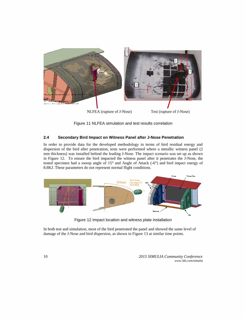
10 2015 SIMULIA Community Conference www.3ds.com/simulia
NLFEA (rupture of J-Nose) Test (rupture of J-Nose)
Figure 11 NLFEA simulation and test results correlation
2.4 Secondary Bird Impact on Witness Panel after J-Nose Penetration
In order to provide data for the developed methodology in terms of bird residual energy and
dispersion of the bird after penetration, tests were performed where a metallic witness panel (2
mm thickness) was installed behind the leading J-Nose. The impact scenario was set up as shown
in Figure 12. To ensure the bird impacted the witness panel after it penetrates the J-Nose, the
tested specimen had a sweep angle of 15° and Angle of Attack (-6°) and bird impact energy of
8.8KJ. These parameters do not represent normal flight conditions.
Figure 12 Impact location and witness plate installation
In both test and simulation, most of the bird penetrated the panel and showed the same level of
damage of the J-Nose and bird dispersion, as shown in Figure 13 at similar time points.

2015 SIMULIA Community Conference 11 www.3ds.com/simulia
1.8 ms 3 ms 4.8 ms
Figure 13 NLFEA results (above) and test (below) results at equivalent time of impact
The energy of the bird debris impacting onto the witness plate was also accurately captured by the
analysis. This is demonstrated by the close correlation of witness plate out of plane permanent
deformation as shown in Figure 14. Simulation predicted maximum out of plane displacement
within 0.7% of the test.
Simulation Test
Figure 14 Predicted and test permanent deformation of witness plate
The dispersion or spread of the bird debris as it penetrated the J-Nose and moved through towards
the witness plate was also captured accurately by the simulation. This is demonstrated in Figure

12 2015 SIMULIA Community Conference www.3ds.com/simulia
14, which shows the bird dispersion in test and simulation at the time the bird first impacts the
witness panel.
Simulation Test
Figure 14 NLFEA and test bird dispersion on impacting witness plate
The overall trend of strains measured at the rear face of the witness plate during the impact
correlated well with the simulations, as shown for a typical gauge in Figure 15. This supports that
the analysis captured accurately the energy and location of debris impacting the witness plate.
Figure 15 Strain correlations (simulation and test)
Figure 16 show the kinetic energies obtained in the simulation. The first drop in energy is caused
mostly by bird impact with the J-Nose panel while the second decrease in energy is mainly due to
the bird impact with the witness plate. From high-speed footage, the time interval between the bird
initial impact of J-Nose and witness plate was estimated to be 8.5ms compared with 8 ms in
simulation. Therefore, the average bird velocity after impact with the J-Nose was predicted well
by the analysis. This coupled with the good correlation of the amount and dispersion of bird
debris penetrated into the J-Nose (shown in Figures 14 and 15) indicates that the kinetic energy of

2015 SIMULIA Community Conference 13 www.3ds.com/simulia
the bird debris passing through the J-Nose, and therefore impacting onto the witness plate, was
accurately captured.
Figure 16 Model, bird and witness panel KE energy
3. Secondary Bird Impact on Witness Panel after J-Nose Penetration - SPH Bird
The new SPH capability in Abaqus/Explicit was used to perform some correlation based on the
available test results. For this purpose a SPH bird model was generated with a particle
arrangement of constant distances based on the Lagrangian bird geometry. Variations in particle
number were carried out to identify the influence on the results. A good compromise in accuracy
and run time on simple targets was found with the configuration shown in Figure 17.
Figure 17 4lb SPH bird model
The material model was not changed and taken from the Lagrangian bird model. The analysis in
section 2.4 was repeated with this SPH bird model.
~2kJ
~5kJ
~8ms
Model Kinetic Energy
Bird Kinetic Energy
Witness Plate Kinetic Energy

14 2015 SIMULIA Community Conference www.3ds.com/simulia
In the SPH bird simulation, localised rupture of the J-Nose is shown in Figure 18 and this
compared well with test and simulations using Lagrangian bird (Figure 13).
Figure 18 Rupture of the J-Nose after impact
Some bird debris deflected at the outer surface of J-Nose as shown in Figure 19, in a similar
manner to Lagrangian bird simulation (Figure 13). The main bird mass travelled inside the J-Nose
towards the witness plate causing it to plastically deform.
1.8 ms 3 ms 4.8 ms
Figure 18 Perforation of J-Nose using SPH bird
Localised rupture of the J-Nose is shown in Figure 19 and this compared well with test (Figure 13)
and simulations using Lagrangian bird (Figure 13).
Using the SPH bird, the permanent out-of-plane displacement was predicted to be 26% less
(Figure 20) compared to the test result. A potential reason identified was the deformed status of
the SPH bird model just before the impact of the witness panel which showed some deviation
compared to the Lagrangian bird model. For the SPH bird simulation, it was not possible to extract
the energy curves as was done for Lagrangian bird (Figure 16) due to the current limitation in the
code. Such correlation would have shed more light on the differences between the SPH and
Lagranian results.

2015 SIMULIA Community Conference 15 www.3ds.com/simulia
Figure 20 Deformation of witness panel in the simulation after impact
Additional test correlation activities to provide a more robust and accurate SPH bird model
concerning bird strike are ongoing. Providing advantages in analysis run time and material
separation the SPH approach can be a candidate to replace the Lagrangian bird model in case of
more complex impact cases.
4. Conclusions
A programme of test and simulation campaign has been briefly outlined in this paper for method
validation of composite sandwich structure damage prediction due to bird strike. The methodology
was able not only to predict the onset of damage but also the penetration of the J-Nose and bird
dispersion. The numerical methods, mainly based on Lagrangian bird, can be used with confidence
for analytical work to support design on similar sandwich panel construction provided the relevant
material data. Simulations were also performed using SPH bird and the results were correlated
with test and Lagrangian simulation results.
5. References
[1] FAA Report, “Wildlife Strikes to Civil Aircraft in the United States 1990–2013”, National
Wildlife Strike Database, July 2014.
[2] http://wildlife.faa.gov
[3] EASA Report, “Bird Strike Damage and Windshield Bird Strike”, EASA.2008.C49, 2009.
6. Acknowledgement
The authors would like to thank the contribution of David Coldbeck of Spirit AeroSystems
(Europe) Ltd in providing the tests data, Richard Gibbon of Frazer-Nash for parts of the
simulations and Etienne Maillard of SONACA for the valuable discussions on the simulations and
providing bird impact tests on generic fixed leading structure for correlation.