u.s. nuclear regulatory commission region ii
TRANSCRIPT
U.S. NUCLEAR REGULATORY COMMISSION
REGION II
Docket Nos: 50-269. 50-270, 50-287, 72-04 License Nos: DPR-38, DPR-47, DPR-55. SNM-2503
Report No: 50-269/97-12. 50-270/97-12, 50-287/97-12
Licensee: Duke Energy Corporation
Facility: Oconee Nuclear Station, Units 1, 2, and 3
Location: 7812B Rochester Highway Seneca, SC 29672
Dates: July 27 - September 6, 1997
Inspectors: M. Scott, Senibr Resident Inspector S. Freeman, Resident Inspector E. Christnot, Resident Inspector D. Billings, Resident Inspector R. Moore, Regional Inspector (Sections E4.2, E8.5 to E8.9) H. Whitener. Regional Inspector (Sections M8.6,.8.7) N. Economos, Regional Inspector (Sections M8.3 to M8.5) W. Stansberry, Regional Inspector (Sections S1 to S5. S8)
Approved by: C. Ogle, Chief, Projects Branch 1 Division of Reactor Projects
Enclosure 2
9710230065 971006 PDR ADOCK 05000269 G PDR
EXECUTIVE SUMMARY
Oconee Nuclear Station, Units 1, 2, and 3 NRC Inspection Report 50-269/97-12,
50-270/97-12, and 50-287/97-12
This integrated inspection included aspects of licensee operations, engineering, maintenance, and plant support. The report covers a six-week period of resident inspection, as well as the results of announced inspections by four regional inspectors.
Doerations
Receipt and storage of the new fuel in the spent fuel pool was conducted with appropriate procedures and good communications. (Section 01.2)
0 During the discovery and evaluation period of increased reactor coolant system leakage from valve 2LP-1, the inspectors concluded that: operators were following the applicable Technical Specifications conservative decision making was evident: and management was involved with the evaluation. The inspectors considered the licensee's actions prudent and well thought out. (Section 01.3)
o The inspectors concluded that the Unit 2 planned shut down and cooldown activities for 2LP-1 work were performed effectively. (Section 01.4)
o A Non-Cited Violation was identified for a motor operated valve design deficiency implementation addressed in licensee event report 50-269/95-08. (Section 08.3)
Maintenance
0 The inspectors concluded that the maintenance activities listed in the general work observation section were completed thoroughly and professionally. (Section M1.1)
o During licensee maintenance activities to determine letdown storage tank reference leg fluid evaporation, the inspectors concluded that the replacement of the Unit 2 instrumentation test tees was performed in accordance with approved procedures with quality control and supervisory oversignt. The inspectors also concluded that no appreciable evaporation occurred. The performance of the personnel invo ved was considered excellent. (Section M1.2)
During the dual Keowee Hydro Plant outage. the inspectors concluded that maintenance activities were accomplished in accordance with approved procedures, personnel were knowledgeable in the systems, practiced good engineering judgement, and had sufficient supervi sory oversight. The inspectors also concluded
Enclosure 2
that the material condition of the equipment observed was good. (Section M2.1)
The failure to detect a potentially unacceptable valve stroke surveillance in a timely fashion is identified as a weakness. However, licensee management's disposition of the issue when identified was good. Corrective items were appropriately addressed or captured by the licensee's corrective action program. (Section M3.1)
O During this period, the licensee increased the normal operating voltage of the Keowee main transformer and the unit startup transformers by altering transformer tap positions. The work was performed on a QA-1 safety-related piece of equipment without using the work order invoked procedure (the procedure was struck through or lined out as allowed under local instructions). An inspector followup item was identified to review the requirements concerning quality assurance with regard to safety related equipment. (Section M3.2)
Engineering
o During a prorammatic review of the Updated Final Safety Analysis Report, the ficensee discovered that a fuel enrichment statement had not been addressed by the 10 CFR 50.59 evaluation. The licensee entered the discrepancy into their corrective action program. 'An Unresolved Item has been opened. (Section E1.1)
o The inspectors concluded that the Keowee Hydro Plant modifications were installed in accordance with app roved packages with supervisory and engineering oversight. The replacement of the voltage regulator motor timer was an example of good engineering activities. (Section E1.2)
o The licensee initiated adequate measures to track and evaluate water hammers in the various piping systems. (Section E2.1)
* The partial discharge test of the Keowee Hydro Plant underground cable was under the control of engineering personnel. The activities were conducted in a deliberate and professional manner. The test was performed without difficulty. (Section E2.2)
O An existing minor body to bonnet leak worsened on a Unit 2 Low Pressure Injection valve that was unisolatable from the RCS. The inspectors concluded that the expected leak repair activities: were discussed with appropriate management involvement: had good engineering input had appropriately developed procedures; and had an approved method for injecting approved sealant with appropriate
Enclosure 2
3
on-line sealing guidance for ASME Class 1 and 2 components. (Section E2.3)
During a degraded grid undervoltage relay setpoint change, workersdid not have as-found set points evaluated due to a potential procedure problem. This test control issue was left as an unresolved item until the licensee completed a corrective action review. The licensee understood the nature of the problem and initiated appropriate corrective evaluation. (Section E3.1)
o Engineering and site management have recently instituted a new focus and direction for the plant through process improvement efforts. Preliminary output from the effort Kos been positive. (Section E4.1)
o The licensee implemented appropriate measures to incorporate lessons learned from the Unit 3 integrated control system modification into the Unit 1 modification. Design and operational deficiencies identified in the Unit 3 modification were adequately addressed for Unit 3 and addressed in the Unit 1 design and modification implementation procedure changes. (Section E4.2)
0 Engineering management has instituted a practice of monthly system engineer tours with non-licensed operators. (Section E4.3)
Plant Support o The inspectors identified a violation for test personnel exiting a
contaminated area without properly removing protective clothing. (Section R4.1)
o1 During an August emergency plan drill, control room drill personnel showed a good questioning attitude and properly used three-way communications. (Section P1.1)
o The licensee used compensatory measures that ensured the reliability of security related equipment and devices. (Section S1i)
o The access controls for vital areas were in compliance with the Physical Security Plin. (Section S2.1)
0 An incident of failure to secure safeguards information properly was a licensee identified, non-repetitive, corrected, non-willful event. Consequently, a Non-Cited Violation was issued. (Section S4.2)
* The security force was being trained according to the Training and Qualification Plan and regulatory requirements. (Section S5.1)
Enclosure 2
* 14
Two incidences of failure to notify security of the termination of personnel in a timely manner were licensee identified, nonrepetitive, corrected, non-willful events. Consequently, a NonCited Violation was issued. (Section S8.1)
* During a fire drill. the inspectors concluded that the method employed for attacking the fire was appropriate, the drill. scenario was good, fire brigade personnel exercised good fire fighting techniques, and the post-fire drill briefing was effective. (Section Fi.1)
Enclosure 2
Reoort Details
SLmmary of Plant Status
Unit 1 began and ended the period at achievable power (73 percent with one reactor coolant pump out-of-service).
Unit 2 began the period at 100 percent power shutting down on September 4, to repair valve 2LP-1. The unit remained shutdown for the rest of the period.
Unit 3 remained at 100 percent power for the entire period.
Review of Uodated Final Safety Analysis Reoort (UFSAR) Commitments
While performing inspections discussed in this report, the inspertors reviewed the applicable portions of the UFSAR that related to the areas ispected. The inspectors verified that the UFSAR wording was consistent with the observed plant practices, procedures, and/or parameters.
I. Operations
01 Conduct of Operations
01.1 General Comments (71707)
Using Inspection Procedure-71707. the inspectors conducted frequent reviews of ongoing plant operations. In general the conduct of operations was professional and safety-conscious: specific events and noteworthy observations are detailed in the sections below.
01.2 Preparation For Refueling
a. Inspection Scope (607051
The inspectors used Inspection Procedure 60705 to verify the adequacy of procedures for the conduct of refueling.
b. Observations and Findings
Unit 1 received new fuel for its upcoming refueling outage scheduled to begin September 18. 1997.
The inspectors observed portions of the receipt, inspection, and storage of new fuel in the spent fuel pool (SFP). Quality Assurance (QA) personnel w.re on hand to verify cleanliness of the fuel and to take receipt. Observations of the movement of spent fuel within the SFP in preparation of the receipt of the new fuel and maintenance activities on the upender were also made. SFP water clarity was excellent.
Enclosure 2
2
c. Conclusions
Receipt and storage of the new fuel in the SFP was conducted with approPriate procedures and good communications.
01.3 Unit 2 Reactor Coolant System (RCS) Leakage from 2LP-1; Low Pressure Injection (LPI) Suction Valve
a. Insoection Scooe (71707. 93702)
Beginning August 27. Unit 2 operators observed a slight increase in RCS leakage. Entry into the reactor building (RB) revealed additional leakage from valve 2LP-1 beyond that which had been identified during a May 22. 1997. startup (0.04 gallons per minute (gpm), see Section 02.1 of Inspection Report (IR) 50-269.270.287/97-05). Operations called the Senior Resident on August 30 keeping him informed. The residents followed the licensee actions through the remainder of the inspection period.
b. Observations and Findings
Several entries into the Unit 2 RB and leak rate checks revealed slowly increasing leakage from the valve 2LP-1 seal ring area. The seal ring provides a gasket-like seal between the body and bonnet of the valve. Fhe valve is the first LPI valve off of the RCS and is unisolatable from the RCS. The unidentified leakage from the Unit 2 RCS increased from 0.17 gpm on July 27, to 0.32 gpm on August 18. and to 0.86 gpm on August 31. 1997.
On August 31, an inspector responded to the site and observed, reviewed. and discussed the leakage with licensee personnel. The amount of identified leakage from the valve pressure seal was determined (from a direct measurement during a RB entry) to be from 0.28 gpm to 0.35 gpm. The possible repair actions.were discussed. Options identified by the licensee included a re-torque of bonnet to body fasteners, an overtorque of these same fasteners, and/or injection with sealing material. The inspectors were informed that the re-torque could be performed by licensee personnel if needed, the over-torque would need approval by the vendor, and the injection of a sealing material would have to be agreed to by the vendor, the sealing material contractor, and licensee engineering personnel. The inspectors were also informed that overall corrective action plan would require management approval. (Additional observations are found in section E2.3 of this report.)
On August 31. the inspectors reviewed the applicable Technical Specifications (TS) and observed that:. TS 3.1, Reactor Coolant System, Section 3.1.6, Leakage, Subsection 3.1.6.1 states, in part, that the reactor must be shut down if the total leakage exceeds 10 gpm. TS Subsection 3.1.6.2 states, in part, that the reactor must be shut down
Enclosure 2
3
if the unidentified leakage exceeds 1 gpm. The inspectors were informed by the licensee that the 0.28 gpm value for measured leakage would be applied as identified leakage.
Based on engineering recommendation, site management reached the * conclusion that the plant was required to be shutdown to effect leak
injection repairs. On September 4 with the valve leakage stabilized * around 0.5 gpm, the unit was brought off line electrically, the reactor
was shutdown, and the RCS partially depressurized. Replacement of the seal ring would have required cold shutdown and core off load.
c. Conclusions
During the discovery and evaluation period of increased RCS leakage from valve 2LP-1, the inspectors concluded that: operators were following the applicable TS: conservative decision making was evident; and management was involved with the evaluation. The inspectors considered the licensee's actions were prudent and well thought out.
01.4 Unit 2 Shutdown Observations
a. Insoection Scope,(71707. 61726)
The inspectors observed shut down and cooldown activities in the Unit 2 control room on September 4 and 5.
b. Observations and Findings
The unit was shutdown and cooled down to 250 degrees Fahrenheit (F) and 350 pounds per square inch gauge (psig). This was done to make repairs to a leaking pressure seal in valve 2LP-1. The plant shutdown and cooldown below hot shutdown conditions was characterized by clear operator communications, effective control by shift supervision, and management oversight. Operators used appropriate procedures, performed a control rod timing test, and maintained close monitoring of the letdown storage tank level. Management on shift was present in the control room. A yet to be approved total RCS leakage computer program was being observed for correctness of function during the shutdown- this program will be utilized as an operator aid as part of a corrective action (EA 97-297, 298) when finally approved. The program operated as expected during the shutdown.
c. Conclusions
The inspectors concluded that the Unit 2 planned shut down and cooldown activities for 2LP-1 work were performed effectively.
Enclosure 2
4
02 Operational Status of Facilities and Equipment
02.1 General Plant Tours
The inspectors used Inspection procedure 71707 to walkdown accessible portions of the following safety-related systems:
o Keowee Hydro Plant 0 Unit 1 and Unit 3 High Pressure Injection (HPI) Pump Areas 0 Unit 1 LPI and Spray Pump Area o Condenser Circulating Water (CCW) Intake Area 0 Unit 1 and 2 Penetration Rooms o Unit 2 Reactor Building o Unit 1, 2. and 3 Low Pressure Service Water (LPSW) Pump Areas
Equipment operability, material condition, and housekeeping were acceptable in all cases. Several minor discre2ancies were brought to the icensee's attention and were corrected. the inspectors identified no substantive concerns as a result of these walkdowns.
08 Miscellaneous Operations Issues (92901, 92700)
08.1 (Closed) Violation (VIO) 50-269.270.287/95-27-01: Inadequate Procedures, Two Examples
This violation addressed two examples of inadequate procedures. The first example was a failure to make a four-hour report as required for having a train of LPI out of service. Nuclear Station Directives (NSD) 202 has been reviewed and revised to prevent recurrence.
The second examole was an inadequate block tag out that allowed the removal of a relief valve which resulted in a spill. The inspector verified that OP/1,2.3/1502/08, Block Tagout Procedure, was revised to designat.e relief valves as boundary valves, if aoplicable. The inspector verified training had been completed for operations shift and staff personnel. The inspector also completed a search of the Problem Investigation Process (PIP) database for other items related to inadequate relief valve tagouts or reportability errors. No items were found that appeared to be related. These items are closed.
08.2 (Closed) Unresolved Item (URI) 50-269.270.287/96-20-01: Standby Shutdown Facility (SSF) Past Operability
During a site-wide review of uncertainties in engineering calculations (started in August, 1996, IR 50-269.270.287/96-16), potential shortcomings in the 1988 revision "0" of SSF Pressurizer Level Instrument .Loop Uncertainty Calculation OSC-2746 were identified. A preliminary review indicated that the SSF pressurizer heaters could potentially be uncovered prior to reaching this heater group's
Enclosure 2
electrical cutoff setpoint. This was based on the fact that the reference leg calculation used a reference leg water temerature of 68F instead of a hypothetical maximum RB temiioerature of 271F. The SSF heaters were located within Group B. Bank 2. of tie pressurizer heaters at a maximum height of 44 inches inside of the pressurizer. Their 126 kilowatts of heat is required to be available within two hours after a loss of offsite power in order to establish and maintain natural circulation. The nine SSF heater elements must be operable for startup. Engineering initiated investigation of the potential problem.
OSC-6847. Revision 0. SSF Pressurizer Level Uncertainty in Support of PIP 97-0273, indicated that post-reactor trip pressurizer water level for the worst case condition would reach a level of 47 inches. Thus, the SSF required unenergized heaters would not be uncovered. Pressurizer and RCS volumes would recover from this level and return to approximately 100 inches prior to the SSF heaters being required on a design basis SSF event. Therefore, with the then existing indication and control system setpoints. the heaters would have been operable. The inspectors reviewed the calculations, discussed the findings with engineering, reviewed the UFSAR sections 7.7.5.2 and 9.6: reviewed TSs 3.18 and 4.20. Further, the inspectors agreed with the conclusions of PIP 97-0273 on the subject. Additionally, the licensee per PIP 97-0273 was enhancing several points in the SSF event scenario documentation and procedures and have redoneOSC-2347 calculation (revision 2) including the new boundary conditions and assumptions. This URI is closed.
08.3 (Closed) Licensee Event Report (LER) 50-269/95-08: Containment Isolation Valve Inoperable Due To Deficient Design Condition (Inclusive of Revision 1)
The substance of the LER is also found in two other documents. IR 50-269,270.287/95-30, Section 3.0 discussed an abnormal/failed November 27. 1995. stroke test of 1RC-6 which is a Unit 1 pressurizer fluid sample valve and RB isolation boundary valve. The failure was discovered when the valve stroked faster than expected. PIP 1-095-1570 addressed past operability finding the valve past technically inoperable since a motor operated valve (MOV) gear and valve type replacement in May 31, 1990. With an incorrect gear ratio installed, the valve would not have closed 'against high (RCS) differential pressure under accident conditions while in a sampling mode of operation. Normally, during sampling, flow is isolated downstream of 1RC-6. The paired series isolation valve. 1RC-7 (springto close pneumatic valve), was operable and would have provided isolation of the sample line. The licensee reviewed other valves on all three units for similar problems. Valve 3RC-5, a pressurizer steam space sample valve which is not routinely used, was also found to be inoperable (January 24. 1996. review, PIP 396-179).
Enclosure 2
6
With the 1995 discovery of the 1RC-6 problem and the subsequent 3RC-5 problem. the licensee took appropriate immediate and long term corrective actions. The valves were aDropriately dispositioned and the licensee submitted a timely LER and followed it with a supplement (revision 1 dated February 19. 1996). An NRC search of the licensee's problem reporting data-base indicated no other examples of similar type events within the two years prior to the time of the event.
The root cause for 1RC-6 problem and the 3RC-5 corrective action review was determined to be deficient design changes. The valves and their operators where changed in 1987 (3RC-5) and 1990 (1RC-6).. During the like-for-like valve operator change.out. the (incorrect) operator gear ratios were not checked on the replacement Limitorque type SMB operators. The design change to the valve operator and valve did not specify the correct gear ratio for either valve. Subsequent valve testing in 1992 of both valves did not identify the gear ratio problems. The licensee's valve testing program was fully implemented in 1993 and the 1995 testing of 1RC-6 did identify the problem. The lack of early (1992 or at installation work package review) problem identification prevented entry into any operationally limiting TS 3.6.3.c limiting condition for operation (LCO) prior to the 1995 discovery date.
Revision 1 of the subject LER indicated that had an accident occurred during Unit 1 pressurizer sampling, the outboard isolation valve. 1RC-7, would have closed to provide necessary isolation. Since 1990. 1RC-7 had no work history or stroke time problems. With only 1RC-7 closed, leakage through this sampling enetration would have been low enough to meet TS 4.4.1.2.3 penetration leakage criteria.
This design deficiency was a violation of 10 CFR 50. Appendix B. Criterion III. Design Control, in that desigp control processes did not ensure that imoortant design aspects were reviewed and controlled. Accordingly, the inspector concluded that this failure to comply n represented a licensee-identified and corrected violation. This nonrepetitive. licensee-identified-and corrected violation is identified as a Non-Cited Violation (NCV). consistent with Section VII.B.1 of the NRC Enforcement Policy. NCV 50-269.287/97-12-01. MOV Design Deficiency Implementation. This LER and Revision 1 to it are closed.
08.4 (Discussed- ODen) VIO 50-269,270.287/96-05-01: Failure to Make Proper 10 CFR 50.72 Notification
Since this subject violation was identified, several other documents have been issued or events occurred that may impact item closure. These are as follows:
On June 19, 1997, a letter from the NRC's Office for Analysis and Evaluation of Operational Data (AEOD) was issued regarding the licensee's reporting practices.
Enclosure 2
7
On July 30. 1997. the Region II NRC office issued Inspection Report 50-269, 270. 287/97-11 that addressed a reporting practice (Section IV) which has vet to be resolved.
o On August 27, 1997. EA97-297. 298 Notice of Violation was issued that included enforcement discretion for a licensee reporting practice (cover letter and enclosure 2).
o On September 4. 1997, the licensee issued a letter responding to the June 19 AEOD letter. In that letter, the licensee .asked for a meeting to discuss reporting practices.
Until the above components are reviewed and discussed, this item shall remain open.
II. Maintenance
M1 Conduct of Maintenance
M1.1 General Comments
a. Insoection Scooe (62707. 61726)
The inspectors observed all or portions of the following maintenance activities.
o IP/0/A/0310/012B Engineered Safeguards System Logic Surveillance Test Online Channel 3
o PT/3/A/.0202/11 High Pressure Injection System Performance Test
o OP/0/A/1102/06 Encl. 3.3 Procedure For Removal From and Return To Service of 6900/4160/600 Volt Breakers
0 MP/OA/1500/008 New Fuel Receipt
o . Work Order (WO) 97052701-13 Replace STAR Modules 3ICSCORC06, 3ICSCORCO7. and 3ICSCORCOS
0 WO 97027649-01 Change Degraded Relay Setpoints
Enclosure 2
8
b. Observations and Findinas
The inspectors found the work performed under these activities to be professional and thorough. All work observed was performed with the work package present and in use. Technicians were experienced and knowledgeable of their assigned tasks. The inspectors frequently observed supervisors and system engineers monitoring job progress. Quality control personnel were present when required by procedure. When applicable, appropriate radiation control measures were in place.
c. Conclusion
The inspectors concluded that the maintenance activities listed above were completed thoroughly and professionally.
M1.2 Evaporation in Reference Legs for Letdown Storage Tank (LDST) (Unit 2)
a. -section _Scooe_627071
The inspectors observed and reviewed the activities involved with the Unit 2 LDST level instrument reference legs. IR 50-296.270,287/97-02. identified concerns involving the instrumentation for the LDSTs in Units 1. 2, and 3. The specific maintenance activities observed were to check for evaporation from the reference legs. IR 50-269.270,287/97-08, an Augmented Inspection Team (AIT) report, also identifies concerns involving compression fittings.
b. Observations and Findings
On July 28. the inspectors observed instrumentation and electrical (I&E) maintenance workers perform a verification test for possible evaporation from both of the LDST reference legs. If evaporation had occurred, the level would have indicated higher than actual.
Prior to the work activities, the inspectors attended a pre-job briefing in the I&E work shop. The pre-job briefing emphasized expectations for items such as safety, questioning attitude, and following procedures. At the work site, the inspectors observed that the test tees, with compression fittings, on the level instruments, 2HPI LT 0033P1 and P2. were replaced with new ones prior to the testing activities. The inspectors noted, from a review of procurement documents. that the tees were Swagelok and were American Society of Mechanical Engineers (ASME). Section III, certified. The inspectors also observed, during the installation, the following: that the threads on the tee's and fittings were inspected the tubing and tee's were inspected for foreign material and the fittings were verified as being snug tight by the use of a template. The inspections and verification were performed by a quality control inspector and the technicians. A leakage test was performed satisfactorily after the installation.
Enclosure 2
The inspectors also reviewed the following documents and procedures:
Procedure IP/0/A/0075/010. Instrument Line, Impulse Line Filling. Revision (Rev) 3;
o Procedure IP/0/A/5090/001, Tube Fitting and Tubing Installation. Rev 1:
W WO 97043780 with tasks 01, 02 and 03; and
o Procedure IP/0/B/0202/001F. High Pressure Injection System Letdown Storage Tank Level Instrument Calibration, Rev 31.
Among the concerns identified in the AIT inspection report. Section M8.1.b. Compression Fitting Issues, were: the mixing of parts from different manufacturers: foreign material exclusion: and the overtightening of fittings. The inspectors observed during the review of procedure IP/0/A/5050/001 the following:
* section 3.1.4.B stated, in part, do not mix or interchange parts of tube fittings from different manufacturers;
o enclosure 4.8. Swagelok Fittings Installation, of the procedure, section 4.8.3 required a check for no foreign material:
o section 4.8.3. of the enclosure, required a check for no scratches, deformations, or damaged threads:
o a note following section 4.8.10. insert tubing with fittings, stated, if resistance is felt when threading nut finger tight the fitting should be replaced; and
o section4.8.11 required that the fittings be tightened to snug tight.
The fittings on the level instruments were changed when it was discovered that resistance was felt when finger tightening the nuts.
The inspectors observed the check for evaporation from the LDST reference legs. An as-found reading for reference leg P2 was taken and indicated 86.72 inches. The reference leg was felled in accordance with procedure IP/0/A/0075/010. An as-left reading was taken and indicated 86.62 inches. The same process was performed on reference leg P1 with the as-found indicating 86.48 inches and the as-left indicating 86.44 inches. This procedure was last performed three months ago. The maximum allowed difference per procedUre IP/0/B/0202/001F was 0.75 . inches. The inspectors noted with the differences in the as-found and the as-left indications being 0.04 inches and 0.10 inches that no appreciable evaporation occurred.
Enclosure 2
10
c. Conclusions
During licensee maintenance activities to determine LDST reference leg fluid evaporation, the inspectors concluded that the replacement of the Unit 2 instrumentation test tee's were performed in accordance with aporoved procedures with Quality Control and supervisory oversight. The performance of the personnel involved was considered excellent.
M2 Maintenance and Material Condition of Facilities and Equipment
M2.1 Maintenance and Material Condition of Keowee Hydroelectric Plant (KHP)
a. Insoection ScoDe (62707)
During a dual KHP outage. the inspectors observed, reviewed, and discussed major maintenance activities on and the material condition of equipment at the KHP. The activities involved the KHP Unit 1 and Unit 2 voltage regulators, batteries, and the hydraulic water turbine governor systems. The material condition included various pumps, air compressors, and fire protection deluge systems.
b. Observations and Findinqs
The major maintenance activities were controlled by maintenance WO and procedures. Among the WOs observed were those listed in section M1.1 of this report. Among the procedures used were the following:
0 IP/0/A/2005/003, Westinghouse Voltage Regulator Test
0 IP/0/A/3000/026, Battery Corrosion and Connector Resistance
0 IP/0/A/0100/001,.Controlling Procedure for Troubleshooting and Corrective Maintenance
0 MP/1(2)/A/2200/001, Keowee Governor Oil Pumps Assemblies Inspection and Maintenance
o MP/1(2)/A/2200/003. Keowee Governor Inspection and Maintenance
o MP/1(2)/A/2200/006, Keowee Permanent Magnet Generator and Speed Switches
o OP/0/A/1107/011, Removal and Restoration of Current Transformer - Reactor Coolant Above 200 Degrees F
The maintenance activities included:
0 disassembling the connectors on 28 KHP battery cells, removing corrosion, reassembling, and checking connector resistance
Enclosure 2
1 checking and adjusting the voltage regulators for proper operation
* disassembling. inspecting, cleaning. and reassembly of components within the governor and the permanent magnet generator assemblies
During the work activities on the components in the governor for KHP Unit 1. maintenance personnel observed that the shutdown solenoid and net head comparator sub-assembly was loose. The mounting bolts had backed out but not far enough for the sub-assembly to fall. The bolts were inspected by the system engineer, reinstalled, and torqued to 30 foot-pounds using thread locking compound. The corresponding Unit 2 sub-assembly was checked immediately but did not appear to be loose. After Unit 1 was returned to service, the Unit 2 subassembly mounting bolts were similarly inspected, reinstalled, and also torqued to 30 foot-pounds with the locking compound present.
The inspectors observed that during the performance on Unit 1. of Section 10.9, Voltage Error Detector Module Test, of procedure IP/0/A/2005/003. the technicians were having difficulty with the Unit 1 module adjustments. The difficulty with the adjustment was because the gain on the card was at the high end of its range: this condition probably had been that way since Keowee unit startup but had not affected unit performance. The inspectors observed that the gain on both the KHP 1 and 2 modules were readjusted to a- more median prescribed (lower) setting. The gain adjustment of the voltage error detector module card was an example of good engineering and supervisory oversight.
c. Conclusions
During the dual Keowee Hydro Plant outage, the inspectors concluded that maintenance activities were accomplished in accordance with approved procedures, personnel were knowledgeable in the systems. practiced good engineering judgement. and had sufficient supervisory oversight. The inspectors also concluded that the material condition of the equipment observed was good.
M3 Maintenance Procedures and Documentation
M3.1 Stroke Time Testinq of Safety Related Valves (Units i 2 and 3
a. Inspection Scooe (61726)
As a result of a supervisory review, licensee personnel discovered that a Unit 2 HPI suction valve potentially did not meet the stroke time acceptance criteria during a surveillance test. The discovery was made six days after the completion of the test.
Enclosure 2
b. Observations and Findinas
Licensee personnel performed a surveillance on July 31 which stroke time tested HPI suction valve 2HP-25. (The valve and 2HP-24 are suction valves in the HPI system.) An approval review of the surveillance was performed on Aug ust 6. During the review, it was discovered that the valve potentially did not meet the stroke time acceptance criteria. The stroke time was recorded as 14 seconds and the acceptance range was 11 to 13 seconds. The UFSAR time limit for this valve was 14 seconds (integer valUe). The valve was declared inoperable, a stroke time test was re-performed, the procedure tester was sought for interview, and a PIP was initiated.
On August 7, the inspectors attended a management meeting at which all HPI suction valve testing for all units was discussed. Among the topics of discussion were the stroke time testing and the lifting of links during engineered safeguards (ES) testing of the valves. The lifting of the links disabled the automatic operation of the suction valves. The rounding off of stroke time testing results was also discussed. The inspectors were informed that the valve was retested and indicated a time of 13.48 seconds that was consistent with the interview debrief of the July 31 procedure tester. During fact finding,.it was found that this particular valve traditionally tested around this stroke time length. The PIP described the problem as a recording error where the tester had mistakenly written down the maximum time as the stroke test time.
.A decision at the management meeting was made to place the ES testing procedures for the suction valves on hold, initiate changes to the applicable procedures, and implement the procedure changes..
The inspectors observed, reviewed, and discussed this issue with the licensee. As a result of observations and discussions four concerns were identified. The first concern involved the stroke time testing review of valve 2HP-25. The second concern involved the lifting of links during testing. The third concern was associated with the second and involved entering an applicable limiting condition for operation (LCO) during the time that the links were lifted. The fourth concern involved Dersonnel performing stroke time testing, and other testing, in that results were rounded off.
Among the items reviewed for the concerns were:
0 Procedure PT/2/A/0152/11, HPI System Stroke Test. Revision 3;
* PIP 2-097-2421, Stroke time of 2HP-25 recorded at 14 seconds:
o Procedure PT/0/A/0310/012A, ES Logic Subsystem 1 On Line Test, Change 26 and Revision 27:
Enclosure 2
13
PIP 0-097-2429. ES testing of HPI suction valves: and
* PPT/0/A/0310/013A. ES Logic Subsystem 2 On Line Test. Revisions 31 and 32.
The inspectors observed from the review the following:
* section 9.0. subsection 9.1, of stroke test procedure directed that times be rounded off up or down to whole numbers;
o section 10.9.5, subsections 10.9.5.b. c. and d of change 26 of the logic subsystem 1 test directed electrical links be lifted and the operators be informed that Unit 1. 2, or 3 HP-24 valve will not be aDle to perform the intended safety function (during this out-of service period):
o section 10.9.5 and subsections 10.9.5.b. c and d of revision 31 of the subsystem 2 test directed the same activities except Unit 1. 2, or 3 HP-25 valve was affected: and
o revisions 27 and 32 respectively removed the requirement to open the electrical links.
The inspectors' review results of the above concerns are as follows:
o The operations staff did not remember such a recording error previously nor had they had a previous problem in the reviewing stroke test data on the shift that it was accomplished. Inspectors reviewed the PIP data base to substantiate this information. As a result of this isolated case, the inspectors observed that unit operations supervisors were directed via written shift guidance to review and verify the results of the operations test group's acceptance criteria.
O The licensee had historically lifted the ES signal links to prevent reactivity changes during ES logic testing in that the orated water storage tank (BWST) head of water could flow into
the suction of HPI pumps. Due to recent operations department agreements and procedure changes LDST pressure has been increased during testing to account for BWST head thereby minimizing reactivity changes. Testing of suction valves have been altered to delete the lifting of the links.
o The inspectors reviewed the historical operator logs for the reriods when suction valve surveillance was performed. Applicable
COs were entered when the links were lifted.
o At the direction of operations management, specific round off requirements have and are being added to the valve stroke
Enclosure -2
14
procedures. Also, as a side issue, although a preliminary overview of their personnel revealed no problems, I&E staff have agreed to review their rounding off methodology in the near future.
The PIP corrective action and other information became available as the investigation proceeded. The management decisions and licensee's preliminary corrective actions determined that: in this case, rounding of stroke time was performed incorrectly and that individual has been counseled; the length of time it took to review the stroke test was excessive but was an isolated case (with procedure changes forthcoming): removal of valve control electrical links was unnecessary and procedurally deleted: and overall valve testing expectations have been clarified.
The licensee revealed additional facts concerning the valves. A valve open position of approximately 17 percent would provide sufficient flow for the HPI pumps. This would occur at 3-4 seconds after start of stroke. One HPI suction valve would provide enough flow for all three HPI pumps.
c. Conclusions
The failure to detect a potentially unacceptable valve stroke surveillance in a timely fashion is identified as a weakness. However, licensee management's disposition of the issue when identified was good. Corrective items were appropriately addressed or captured by the licensee's corrective action program.
M3.2 Startup Transformer Tan Chanoes
a. InsDection Scone (62707)
During this period, the licensee increased the normal operating voltage of the Keowee main transformer and the unit startup transformers by altering transformer tap positions. The inspectors observed portions of this work (see Section P1.2).
b. Observations and Findins
During the startup transformer tap changing activities, maintenance reviewers closing the work package initiated PIP 3-97-2600 on the work covered under the minor modification OE 9370. The PIP identified two questions dealing with (1) the acceptability of reusing aluminum bolts, and, (2) the fact that a WO invoked procedure was not used during the work (the procedure was struck-through or lined-out as allowed under local instructions). Based on their review of this issue and examination of the fasteners, the inspectors have no concerns with the reuse of the fasteners. The rationale in the PIP for the second problem
Enclosure 2
SII
was that the work was being performed on a QA-1 (safety-related) niece of 20Ui pment and the PIP originator felt that the lined out orocedure shoul'd have involved QA inspection on the work. The i nspector.will review the requirements concerning QA with regard to safety-related work. This is identified as Inspector Followup Item (IFI) 50269,270.287/97-12-04. Maintenance Oversight.
M8 Miscellaneous Maintenance Issues (92902)
M8.1 (Closed)_LER 50-287/95-01: Packing Leak Due to Inappropriate Action Results in Unit Shutdown
IR 50-269.270.287/95-17 discussed this event and described the root cause. The licensee has subsequently implemented a corrective action plan (described in PIP 3-095-0923) that included repacking two steam valves which had been packed using the same packing as the failed valve. changing two procedures to provide for better verification of packing follower installation, and purchasing a fiber optic camera to allow for better inspection of valve stuffing boxes.
The inspectors reviewed the plan and determined it was adequate. The insDectors found the corrective actions specified in PIP Report 3-0950923 imolemerted as stated except for the procedure changes'. Corrective Action humber 3 specified three changes to Procedures MP/O/A/1200/001. Valves - Non NRC 89-10 - Adjusting and Packing: and MP/O/A/1200/001D. Valves - NRC 89-10 - Re placing and Adjusting Packing. One of the changes specified a double verification step had been added for technicians to sign that the packinq follower was not cocked. The inscectors found this steD in Procedure MP/O/A/1200/001 but not in Procedure MP /O/A/1200/001b. Procedure MP/O/A/1200/001D only contained a caution on cocked packing followers. The inspectors later determined, after discussions with maintenance manacptment. that procedure changes specified in Action Number 3 were actually implemented by Corrective Action Number 4 to' the PIP report and that maintenance Dersonnel had incorrectly specified the procedure changes in Action Number 3 after Action Number 4 had been completed. The inspectors agreed the corrective actions had been implemented, however, the inspectors also considered the documentation in the PIP report to be poorly done without proper attention to detail.
The inspectors further determined that, at the time of the event. maintenance personnel did not properly follow procedures when repacking Valve 3RC-3, constituting a violation of 10 CFR 50. Appendix B, Criterion V, Procedures. This non-recetitive. licensee-identified, and corrected violation is being treated as a Non-Cited Violation, consistent with Section VII.B.I of the NRC Enforcement Policy, NCV 50287/97-12-08. Failure to Followi Valve Packing Procedure.
Enclosure 2
16
M8.2 (Closed) LER 50-287/95-02: Drop of Control Rod Group Due to Unknown Cause Results in Reactor Trip
This event was discussed in IR 50-269,270.287/95-18. No new issues were revealed by the LER.
M8.3 (Discussed - Open) VIO 50-269.270.287/96-10-03: Weld Procedure Qualifications Welded, Tested, Certified and Approved by Same Individual
This violation was identified when the inspectors determined that the licensee's weld procedure qualification program failed to provide an independent QA review for the qualification process.
The licensee acknowledged the violation on September 11. 1996. The licensee attributed the violation to a lack of sufficient guidance in the Duke Power Welding Program. Procedure L-100 in that it did not reflect the independent QA review requirement of American National Standards Institute (ANSI) N-18.7-76.
Corrective actions taken to address this oroblem included discussion with technical personnel to assure that they understood the QA requirement for independent review of qualification records. Also. the licensee revised the subject document such that it requires that the QA review be performed by an individual other than the one who performed the qualification.
By this review, the inspectors ascertained that the revised procedure. L-100. did not include directly or by reference the applicable QA documents, e.g., Duke's QA Topical Report. Duke- or ANSI 18.7-76. The licensee plans to revise the subject procedure to reference the applicable QA commitments.
The inspectors discussed this observation with the cognizant engineer who agreed to discuss it with management before incorporating it. in the L-100 procedure. The inspectors indicated that this item will remain open until final action had been taken on this matter.
M8.4 Closed) URI 50-269.270.287/96-17-04: Engineering Evaluation for the Replacement of Carbon With Stainless Steel Piping
This item was identified due to a concern over the possibility that large diameter e.g., greater than or equal to 24-inch, carbon steel piping could have been replaced with piping made from stainless steel material without sufficient engineering analysis to verify adequacy as required by Revision 17 of theapp licable pipe specification PS300.4. The licensee's review of data collected during tne pipe branch connection analysis revealed that there was only one location per unit where this substitution could have taken place. This location was identified as a 24-inch diameter pipe section, downstream of the "D
Enclosure 2
SII
17
heater drain tank pumps. This pipe section connects the heater vent/drain system to the condensate system.
Through discussions with the cognizant engineer and review of applicable drawings. the inspector verified that Pipe replacement in the aforementioned location had not taken place. The inspectors concluded that the licensee's investigation and findings were satisfactory.
M8. S-(Discussed - Ooen) VIO 50-269.270.287/96-17-09: LPSW Modification Did Not Meet ASME Code Section Xi Non-Destructive Examination (NDE) Requirements
This violation was identified when the insoectors determined that the licensee had failed to perform Code required examinations on certain newly fabricated welds in the LPSW "B" line header.
The licensee acknowledged the violation on March 12, 1997 and listed the corrective actions taken to fix the problems and the actions taken to preclude their recurrence. Through di scussi ons with cognizant personnel and a review of records, the inspectors verified that the subject welds were successfully hydrostatically tested per code requirements. QA Welding Technical Support and Engineering had been assigned specific responsibilities and were given auoropriate training for implementing special code requirements as applicable. Also, certain process control forms had been revised to address more clearly post-maintenance testing requirements, e.g.. hydro versus an alternate test method. Steps taken to preclude the recurrence of this problem were addressed as near and long term corrective actions in PIP 0-097-1691. These actions were the result of a Quality Improvement Team (QIT) assessment of Oconee's Post Maintenance/Modification Testing (PMT) Program. Previous root cause inspections found that the program was fragmented and that there 'was not sufficient technical support and management oversight to assure that the program served its intended function.
A summary of the major recommendations made by the QIT included: development of a comDrehensive guidance document addressing PMT activities: establish scheduling ties and reporting methods: establish a PMT Working Group: establish a test .coordinator and adequately staff PMT functions: and formalize weld process control and PMT testing requi rements. These recommendations were subsequently evaluated and grouped into short and long term categories in PIP 0-097-1691.
The short term recommendations were to be resolved prior to the upcoming Unit 1 refueling outage. The insoectors stated that this matter would remain ooen until the inspectors had an opportunity to review the identified short term recommendations for adequacy prior to the aforementioned outage.
Enclosure 2
18
M8.6 (Closed) IFI 50-269.270.287/93-20-01: Instrument Impulse Lines and Associated Inservice Inspection (ISI) Requirements
The inspectors had identified instrument impulse lines off of safety related Emergency Core Cooling Systems (ECCS) which were seismic, QA-1, safety related lines up to the first instrument root valve (pressure boundary) and were non-seismic, non-safety related lines from the root valves to the instruments. The inspectors had raised the concern that a loss of inventory or release of radiation could occur if the non-seismic portions of the lines fail since the root valves to.these non-safety related instruments are normally open valves.
The licensee performed an investigation of this situation -and a review of documents to determine the required status of these lines. PIP report No. 0-094-0309 was opened to track actions and document results of this investigation. The inspectors reviewed UFSAR Section 3.9.3.1.3. and a letter dated May 6. 1996, from Duke Power Company (J. W. Hampton) to the NRC formally acknowledging a verbal commitment made to the NRC to upgrade .ECCS instrument lines to QA-1 status. Also, the insoectors reviewed the evaluations and corrective actions described in PIP 0-0940309. reviewed portions of a draft calculation, OSC-6163, which . documented the results of instrument line walk down inspections, and confirmed that plant drawings and instrument details had been upgraded to show the instrument impulse lines as QA-1. QA-1 status assures that these lines will be maintained i.n accordance with 10CFR50. Appendix B. The inspectors also reviewed several walkdown packages. Wal kdown check sheets included items such as the following:
* verify instrument line is flexible enough to absorb the thermal and seismic movements;
0 verify sufficient clearance exist such that seismic interaction with adjacent equipment is not a concern:
o verify instrument line is sufficiently supported to ensure failure will not occur during a seismic event: and.
o verify instrument valve is sufficiently supported to ensure that failure will not occur during a seismic event.
The insoectors concluded that through the corrective actions the licensee has met the coimmitment made to the NRC to upgrade the ECCS instrument impulse lines to QA-1 status.
Enclosure 2
19
M8.7 (Closed) URI 50-269/96-04-04: Root Cause Assessment of Failures to Valves 1MS-77 and 1LPSW-254
This item involved failures of valves in two separate systems which are discussed below.
1MS-77, Second Stage Reheater Al Inlet Valve
1MS-77, a non-QA-1, non-safety related valve, failed to go closed on demand. Troubleshooting showed the valve to be wedged in the backseat with the thermal overloads tripped. When attempting to recycle the valve the breaker tripped instantly. The licenee's investigation determined that the open limit switch was set at 2 percent when the procedure required 5 percent. The licensee concluded that the valve was going into the backseat every time the valve was fully opened. This resulted in requiring an excessive amount of motor torque to pull the valve off of its backseat. This problem then led to the motor on the valve operator failing and causing the breaker to trip.
The licensee concluded that the valve failed because of improper valve set up. The cause was personnel error. The root cause was considered inadequate training. Training and Qualification Guide, ETQS # MOV-QLIMITORQUE, was amended to highlight this condition. The inspectors reviewed the guide and confirmed the revised training instructions.
Additionally, the inspectors reviewed the task completion comments, PIP .1-096-0417, and procedure IP/0/A/3001/010, "Maintenance Of Limitorque Valve Operators." The procedure was considered adequate and this issue was considered resolved.
LPSW Valve 1LPSW 254. LPI Cooler Outlet Isolation
Valve 1LPSW-254 is the Unit 1 train A LPI cooler outlet isolation valve. Valve 1LPSW-251 is the flow control valve for the same cooler and is located immediately upstream of 1LPSW-254. Due to numerous LPSW system component failures in the past, an adverse condition was identified. The licensee's identification, testing, and proposed corrective actions are identified and tracked in PIP 0-095-1491. Because of the similar configurations of the LPSW cooler installations. this PIP is applicable to all three Oconee Units.
A review of the numerous LPSW comoonent failures indicated that vibration problems were principal'contributors. Therefore, the licensee performed extensive vibration testing and component inspections. The results indicated that the excessive LPSW system vibrations were caused by flow induced cavitation through the flow control valves. Based on the vibration study and component inspection, the licensee had developed an Urgent Nuclear Station Modification (NSM) 3022 which will.be implemented on each unit at the next refueling outage. The inspectors
Enclosure 2
20
reviewed portions of the Unit 1 modification package, NSM 13022. This modification will replace flow control valves 1LPSW-251 and 1LPSW-252. and associated downstream isolation valves 1LPSW-254 and 1LPSW-256. with valves designed to reduce the flow induced cavitation and noise. Also, flow control valves will be relocated to increase the distance between flow Control and isolation valves. Carbon steel piping immediately downstream of the flow control valves will be replaced by stainless steel piping.
The inspectors concluded that the licensee had identified the root cause and developed necessary actions to correct the vibration problem. The Unit 1 modification package had been developed and was scheduled for implementation at the next Unit 1 refueling outage (September 1997). Units 2 and 3 will receive the same modification. The licensee stated that these modifications are in the preparation stage and will be implemented at the next refuel-ing outage for each unit.
The inspectors concluded that the licensee had identified the root cause. and taken action to correct the problem and prevent recurrence.
I II. E ngjneerng
El Conduct of Engineering
E1.1 UFSAR Fuel Load Requirements
a. Scooe of Inspection (71707. 37551)
Through Oconee site initiated PIP 0-97-2511. the licensee identified that fuel enrichment had not been as specified in the UFSAR Section 4.3-3.1.4. This was discovered during a recent (August 13, 1997) internal site review of the UFSAR.
b. Findings and Observations
The UFSAR section stated in part that "Each fuel rod is identified by an enrichment code, and the desi gn of the reactor is such that only one enrichment is used Per assembly." This was not the case in all Oconee units (starting in 1994 on Unit 2). There are currently multiple batches of fuel in use at Oconee that have axial blankets (regions of reduced enrichment at the upper and lower ends of the fuel rods). Also, the fuel currently being received for the upcoming Uni't 1 outage contains fuel pins of varying enrichment within the same assembly (this is the first such fuel used at Oconee). The 10 CFR 50.59 review that was generated by the corporate office for this upcoming Unit 1 fuel load change did not address this UFSAR statement. TS 6.9 covered fuel analysis methodology and other NRC - licensee transmittals had
Enclosure 2
21
previously approved fuel design techniques with stringent critical parameter limits.
Previous fuel reload and 10 CFR 50.59 analysis were being reviewed by the licensee and a root cause analysis was on-going to determine how the UFSAR requirement was overlooked. The licensee has stated in the above PIP that the there is no present operability concern. Until the licensee completed their 10 CFR 50.59 and fuel load UFSAR revie,, this item will be identified as URI 50-269,270.287/97-12-02. Fuel Load UFSAR Statements.
c. Conclusions
During a programmatic review of the UFSAR. the licensee discovered that a fue enrichment statement had not been addressed by the 10 CFR 50.59 evaluation. The licensee entered the discrepancy into their corrective action program. An URI has been identified on this issue.
E1.2 Modifications to Startup Transformers and Keowee Voltage Requlators
a. Inspection Scope (37828)
The inspectors observed, reviewed, and discussed the installation of minor modifications (MM) to the startup transformers, the degraded grid relays, the KHP main transformer, and the KHP voltage regulators. The activities started on August 18 and completed on August 22. During this time frame, maintenance activities were also observed and are documented in Sections M2.1 and 3.2 of this report.
b. Observations arid Findings
The MM installations observed were the following:
0 MM. 10264, changed the set point on the degraded grid relays:
o MM 9368, changed the taps on startup transformer CT 1. (similar MMs were performed on startup transformers CT2 and 3 as well as the KHP main transformer);
0 MMs 9323 and 9324, installed a new logic network in the KHP Unit 1 and 2 voltage regulators ; and
a MM 9375, changed the relay settings for the KHP main transformer.
The MM for the voltage regulators were installed in order to return the base and voltage adjusters to a preset level when an emergency start signal is received. When the units are operating to the grid the regulators may be set at a voltage output different from the required emergency start output.
Enclosure 2
22
The ins ectors observed the post modification testing. Durin testing of the Unit 2 KHP regulator, a small electric motor timer failed to meet a time required. The motor was replaced under engineering direction and the MM was successfully tested. The test of the startup transformers and the KHP main transformer indicated adequate output voltages.
c. Conclusions
The inspectors concluded that the Keowee Hydro Plant modifications were installed in accordance with approved packages with supervisory and engineering oversight. The replacement of the voltage regulator motor timer was an example of good engineering activities.
E2 Engineering Support of Facilities and Equipment
E2.1 Water Hammer Status
a. Inspection Scope (37551)
The inspector reviewed engineering evaluations of water hammer issues documented in various PIPs. The licensee had a severe water hammer event in 1996 as discussed in IRs 50-269,270,287/96-13 and 50-269,270.287/96-15.
b. Observations and Findings
Following the heater drain line break in late September 1996. the licensee had become more sensitive to water hammer issues. Since that date, approximately 30 PIPs have been generated to have engineering evaluate water hammers that have been identified. For example, these water hammers have been identified in the main steam reheater drain piping. steam separator reheater drain piping, main feedwater piping, and auxiliary steam piping. Engineering continues to evaluate and monitor water hammers as they occur. No major problems have been identified with water hammers to date.
c. Conclusions
The licensee initiated adequate measures to track and evaluate water hammers in the various piping systems.
E2.2 Partial Discharge Testing of Electrical Power Cables (Keowee)
a. Insoection ScopeL375511.
The inspectors observed, reviewed, and discussed, with the licensee's engineering personnel, the performance of a partial discharge test (PDT). The test was performed on the underground 1.3.8 kilo-volt (kV) power cable feeds from the KHP to the transformer CT.
Enclosure 2
23
b. Observations and Findings
On August 5, 1997, licensee personnel and a vender representative (vender-rep) performed a PDT on the six, two per phase. KHP underground power cables. The cables are each rated at 10 kV phase-to-phase. 8 kV phase-to ground, and operate at 13.8 kV phase-to-phase. The cables are approximately 4000 feet long.
The test equipment used by the vendor-rep was especially fabricated for the licensee. It consisted of a view screen, a computer, an operating keyboard, and a floppy drive. The equipment also had calibration devices.
The inspectors observed the determinating and terminating of the cables, the hook up of the test leads, and the performance of the PDT by the vender-rep. The inspectors observed that the activities were documented in WO 96089265 and procedure IP/0/A/2000/01, Power and Control Cable Inspection and Maintenance, Revision 4. The test set up contained a low power/high voltage alternating current source, a high voltage interface device, hookup wiring, and the special test equipment. The PDT on each cable was performed at rated and at 110 percent of rated phase-to-ground voltage.
The inspectors also observed and concluded from the reviews, observation, and discussions the following:
0 the oversight of determinating and terminating of the power cables and the identifying of the specific cables was performed by onsite engineering personnel;
o personnel from corporate and the McGuire Nuclear Station were at the KHP observing the test and were briefed by the vender-rep and engineering personnel;
* the PDT was performed by the skill of the vendor-rep, with assistance and oversight from engineering personnel;
0 information on how the test equipment functioned and how to operate it was shared by the vendor-rep and site personnel:
o the vender rep established a preset trigger level for detecting partial discharges;
o a step-by-step procedure for the operation of the test equipment was not available;
o however, view screen pictures. with explanations, showing various aspects of the PDT were available; and
Enclosure 2
24
the maximum voltage applied during the test was set by engineering personnel and was from 9.02 to 9.4 kV.
The inspectors were informed and observed that no partial discharges were detected above the preset trigger level at rated voltage and at 110 percent of rated phase to ground voltage. The inspectors were also informed that, based on the results of the PDT, the six cables were in excellent condition.
c. Conclusions
The PDT of the Keowee Hydro Plant underground cable was under the control of engineering personnel. The activities were conducted in a deliberate and professional manner. The test was performed without difficulty.
E2.3 Pressure Seal Leak On Valve 2LP-1 (Unit 2)
a. Inspection Scooe (37551)
The inspectors observed, reviewed, and discussed with licensee management. operations, maintenance, and engineering personnel the corrective action plan for the pressure seal leak in valve 2LP-1. The leak is also discussed in section 01.3 of this report. The inspectors also attended working level and management level meetings at which the leak was discussed.
b. .Observations and Findings
The inspectors used NRC Part 9900 Technical Guidance, On-Line Leak Sealing Guidance for ASME Code Class 1 and 2 Components, dated July 15. 1997, during the observations and reviews of the leak sealing activities. Among the items reviewed were the following:
0 Temporary Modification (TM) 1376, Seal Leak Repa.ir on Valve 2LPI1:
0 procedure TN/1/A/1376/TSM/00M, Installation of TSM-1376:
o 10 CFR 50.59. Unreviewed Safety Question Evaluation, for TSM-1376;
o procedure PT/2/A/0152/12. Stroke Testing: and
a maintenance WO 97076613-01.
The insorctors attended several meetings, with both management and engineering, during which the valve was discussed. The inspectors also attended P ant Operating Review Committee (PORC) meetings which also
Enclosure 2

25
discussed the leak. The inspectors observed during-the meetings and reviews the following:
* Managers, i ncluding senior managers. were actively involved in the assessment, options, and evaluation of the leak;
o engineering personnel stated that the injection would be made into a void above the pressure seal ring of the valve, therefore, the pressure boundary was not involved;
a licensee personnel considered the valve as being operable and would remain capable of performing the required safety function throughout the sealing activity;
o the injection would be performed with the primary system at 360 to 380 psig and at 260 to 300 degrees F;
o following the expected successful injection, with the leak stopped, the valve would be stroked to verify operability;
o the cause of the leak was not specifically discussed (historically, an :ngineering evaluation on this valve had existed since the May 22. 1997 startup):
o the valve fasteners were observed to be intact, by the use of video tape, and they appeared to be covered by the boric acid and water solution escaping from the leak:
o engineering personnel stated that the small amount of sealant to be injected, (20 cubic inches maximum), the number of holes drilled (six maximum), the number of injections allowed (maximum of two), and the location of the holes would not affect 1.e structural integrity of the valve:
o a plan was discussed which directed that should the seal fail during the repair activity personnel were to evacuate the reactor building as quickly as possible: and
o engineering personnel stated that the valve would be disassembled, inspected, and the seal ring would be replaced, possibly with a new type, during the next refueling outage.
The inspectors were informed that the valve was a cast valve and technical information only gave minimum thicknesses and not actual thicknesses. The use of a physical drill stop would not apply under these conditions. The method to be used was.that the holes would be drilled slowly, by hand, and would be stooped as soon as pressurized water was reached. The inspectors were also informed that if the leak
Enclosure 2
26
could not be stoyped the plant would be taken to cold shutdown and defueled for rep acement of the pressure seal.
At the end of this report period Unit 2 was at the planned reoair temperature and pressure. The sealing activity had not started..
c. Conclusions
An existing minor body to bonnet leak worsened on a Unit 2 LPI valve that was unisolatable from the RCS. The inspectors concluded that .the expected leak repair activities: were discussed with appropriate management involvement; had good engineering input; had appropriately developed procedures; and had an aproved method for injecting approved sealant with appropriate on-line sealing guidance for ASME C ass 1 and 2 components.
E3 Engineering Procedures and Documentation
E3.1 Degraded Voltage Relay As-Found Condition
a. Inspection Scope (62707. 37551).
The inspectors observed the performance of WO 97027649-01, Change Degraded Relay Setpoints.
b. Observations and Findings
This work order implemented MM ONOE-10264: 27YBDGX. Y. Z Degraded Grid Relay Set Points, which changed the 230KV degraded grid undervoltage relay setpoints by changing the calibration procedure.and then reca :brating the relays using the revised procedure.
On August 18, 1997 technicians changed the setpoints on Degraded Grid Undervoltage Relays 27YBDGX, 27YBDGY. and 27YBDGZ by recalibrating the relays to the new setpoints specified in the modification. The technicians used Procedure IP/0/A/4980/27G, IPE 27N Relay. Revision 5. which had been revised to incorporate the new setpoints, to perform the setpoint change. When technicians measured as-found setpoint values for the relays, the values were out-of-tolerance from those specified in the procedure. However, the technicians did not notify engineering of the out-of-tolerance as-found condition because Procedure IP/0/A/4980/27G contained a step permitting the option of not reporting an out-oftolerance as-found condition if the condition resulted from a procedure change. The revised procedure did not give any guidance as to whether the relay was actually within the tolerance specified from the previous calibration.
The inspectors discussed this with engineering personnel who stated their expectations were for all out-of-tolerance conditions to be
Enclosure 2
27
reported to engineering who would then determine whether or not the condition warranted further corrective action. The inspectors also reviewed several other relay calibration procedures and found all of them to contain a step permitting the option of not reporting an if the condition resulted from a procedure change. The licensee entered the condition into their PIP 0-097-2796.
The circumstances surrounding this issue will be tracked as URI 50-269.270.287/97-12-03, Relay As-Found Conditions, pending review of: 1) the administrative requirements for documentation and evaluation of as-found test conditions, and 2) the determination of the extent to which the option of not reporting an out-of-tolerance as-found condition existed.
c. Conclusions
During a degraded grid undervoltage relay setpoint change. workers did not have as-found set points evaluated due to a potential procedure problem. This was left as an unresolved test control issue until the licensee completed a corrective action review. The licensee understood the nature of the problem and initiated appropriate corrective evaluation.
E4 Engineering Staff Knowledge and Performance
E4.1 Management Activities
a. Insoection Scooe (37551. 40500)
During the period, the inspector observed manacement activities at the site.
b. Observations and Findings
During this period, the licensee has initiated several new process improvement efforts. The inspectors have observed that engineering operability evaluation progress, plant concerns, and action register items have been added to the agendas of the three main plant meetings. This has been formalized in trackable handouts that are actively discussed at each of the meetings. The increased level of detail and the focus that these provide is noteworthy.
The residents attended engineering daily review meetings that have evaluated: the engineering work in progress to suDDort the plant; plant deficiency closeout progress; and modification package pcogress. PIP backlogs have been reduced and additional engineering support added.
Several plant management requested assessments have been accomplished during tne past several months. These have focused on understanding
Enclosure 2
28
plant interactions and problem areas. The inspectors have attended several of the exit meetings of these assessments and local management has responded well to the negative findings particularly in the areas of welding and post modification and maintenance testing controls. Also, the equipment mispositioning assessment has been on going with recent recommendations delivered in PIP 97-2292. The licensee has a major electrical reliability assessment to be completed by the end of the year.
The Site Vice President has held several meetings to communicate clear expectations. He has met with managers and has held a large plant staff general meeting at a local auditorium to clearly discuss recent plant problems and re-identification of expectations. The senior resident attended a portion of the large general meeting and found the presentation to be informative with the message well defined.
c. Conclusions
Engineering and site management have recently instituted a new focus and direction for the plant through process improvement efforts. Preliminary output from the effort has been positive.
E4.2 Unit 1 Integrated Control System (ICS) Modification
a. Insoection Scope (37550)
The inspector reviewed the licensee's activities to incorporate lessons learned from the Unit 3 ICS modification into the upcoming Unit 1 ICS modification. Applicable regulatory requirements included 10 CFR 50 Appendix B. Updated Final Safety Analysis Report (UFSAR). and American National Standards Institute (ANSI) N45.2.11 - 1974, Quality Assurance Requirements for the Design of Nuclear Power Plants.
b. Observattons and Findings
The licensee identified deficiencies during the Unit 3 ICS post-modification.testing which were entered into the PIP process for tracking and resolution. An ICS design feature which initiated automatic feedwater valve control when the ooerator station was in manual and a steam generator (SG) low level limit was reached caused operator confusion (PIP 3-97-0854). This feature will remain in Unit 3 until the next Unit 3 outage. The design feature was deleted from the Unit 1 design as demonstrated by revision DB to Unit 1 drawing 0.M. 201.H-0183.001. Feedwater Control, Loop A Valves and Low Level Limits. Poor control at low power/low feed flow conditions due to the power/flow error signal inconsistency at this condition was corrected by a square root extractor function in the module code for Unit 3 (PIP 3-97-0858). The Unit 1 design was changed to use the level transmitter in the linear mode which provided a more reliable power/flow error signal.
Enclosure 2
29
Inadvertent shift of the ICS component STAR modules to hand (manual) mode was noted (PIP 3-97-1015). The cause was determined to be a characteristic of the module self-checking circuit which was corrected by requiring three points per self-check rather than one. This modification was being programmed into the individual STAR modules. The program code correction implemented to resolve feedwater valve cycling at ten to fifteen percent power resulted in the inadvertent deletion or overwrite of required program code functions (PIP 3-97-0910). The corrective action added barriers to the process for ICS program code revisions.
c. Conclusion
The licensee implemented appropriate measures to incorporate lessons learned from the Unit 3 ICS modification into the Unit 1 modification. Design and operational deficiencies identified in the Unit 3 modification were adequately addressed for Unit 3 and addressed in the Unit 1 design and modification implementation procedure changes.
E4.3 Expandino Engineerin. Knowledoe Base
a. Insoection Scope (71707.-37551
During the course of this period; inspectors observed engineering personnel in the control room and in the plant making rounds with the non-licensed operators (NLO).
b. Observations and Findings
Engineering management provided direction that their staff become more operationally focused. Part of this philosophy was direction for system engineers to perform monthly walkdowns of systems and to accompany a non-licensed operator on rounds. The inspectors observed this being implemented in several instances.
Site engineers were observed to be in the Unit 1 and 2 common control room at the operations morning briefing. The operations Onshift Manager indicated-that these engineers would be going with the NLO on their plant rounds and should be provided any support and information that they requested.
c. Conclusions
Engineering management has instituted a practice of monthly system engineer tours with non-licensed operators.
Enclosure 2
30
E8 Miscellaneous Engineering Issues (92903)
E8.1 (Discussed - ODen) Deviation (DEV) 50-269.270.287/94-24-04: Design Basis Requirements for the Penetration Room Ventilation System (PRVS)
IR 50-269,270.287/94-24 discussed the issue of leakage from the PRVS. Testing in 1992 had revealed that the PRVS ability to maintain a negative pressure was affected by auxiliary building air handling unit/fan combinations. The licensing basis assumes all leakage into the penetration room will be filtered prior to release. There is no provision for any leakage to bypass the PRVS via leakage into the auxiliary building. The only method to ensure all leakage into the penetration room gets filtered is to have the penetration room airtight or at a negative pressure with respect to its surroundings (i.e. both the atmos here and the auxiliary building) during an accident. The licensee has completed extensive testing and sealing of identified leak paths from the penetration room to other surrounding rooms.
The licensee has decided to pursue a licensing approach by uodating the current off-site dose calculations to presently accepted methodology. This will allow the deletion of the PRVS from TS. Implementation of the TS and UFSAR changes have been assigned due dates of December 31. 1997 and July 5, 1998. respectively.
E8.2 Li.ussed - Op en) IFI 50-29.270.287/95-03-01: Clarification of TS 3.3.1
This item addressed HPI operability requirements below 60 percent power. In November 1990 with their then existing engineering analysis, the licensee identified that below 60 percent power an injection line nozzle break could result in insufficient flow to the reactor core assuming a single failure if only two HPI pumps were operable. The licensee 'has committed to revise TS 3.3.1. The revision was submitted to NRC on March 31. 1997. Due to events involving the HPI pumps in April of 1997, the licensee has committed to conduct an HPI reliability study. This study is due to be submitted to the NRC on December 31. 1997. The TS revision will be completely processed following the review of the reliability study; segments of the revision may be completed earlier, based on a September 4. 1997, licensee docketed request.
E8.3 (Closed) ADarent Violation (EEI 50-269.270.287/96-03-02 (EA 96-090): Inoperability of Containment Hydrogen Control Systems
This item addressed a lack of drainage for condensate that could block flow during operation of the hydrogen recombiner. This issue was closed by letter dated April 16, 1996. granting enforcement discretion.
Enclosure 2
31
E8.4 (Closed) LER 50-270/95-02: Incorrect Timer Setting Due to a Design Deficiency Results in a Reactor Trip
The reactor trip of Unit 2 was discussed in IR 50-269,270.287/95-06. The LER stated that modifications would be installed in each unit to change the timer set points for the loss of excitation relays. The inspectors observed that minor modifications ON0E 8045, 8051. and 8085 were installed on Units 1. 2. and 3. respectively, which changed the set points. The set points were raised from 0.8 to 30 seconds. The LER also stated that a review would be performed so that other protective relay timers would be set as required. The review was completed and processes are in place, such as procedure changes and minor modifications, to ensure that both safety related and non-safety related relays have.adjustment information. Based on the licensee's actions this LER is closed.
E8.5 (Closed) VIO 50-287/97-02-06: Inadequate Control of Purchased Material and Equipment
This item addressed inadequate procurement control activities which contributed to the receipt and installation of a safety related eightinch ball valve (LP-40) which did not meet the Duke Power specification referenced in the purchase order. The incorrect reverse acting valve contributed to a loss of RCS shutdown inventory on February 1. 1997. Additional issues associated with this item included an operation's poor practice for manual valve position verification and maintenanceIs poor communication of the abnormal equipment configuration represented by the reverse acting valve.
The licensee's response to the violation, dated July 2. 1997, specified corrective actions to address performance deficiencies by the procurement, operations, and maintenance organizations. The inspector reviewed a licensee vendor follow up audit, operations and maintenance procedure revisions, and training documentation which documented completion of the corrective actions stated in the licensee's response. The inspector concluded that the procurement, operations. and maintenance performance deficiencies which contributed to the installation of the incorrect safety related valve (LP-40) were adequately resolved.
E8.6 (Closed) VIO 50-269.270.287/97-02-08: Inadequate Corrective Action and Design Control for Reactor Building Cooling Unit (RBCU) Fuses
This item addressed the licensee's inadequate corrective action to resolve an identified incorrect fuse installation in the RBCUs. The corrective action did not adequately evaluate the equipment design to determine the appropriate fuse size and type for the application. Additionally, the corrective action did not identify the operability
Enclosure 2
32
significance of the issue and did not properly categorize the associated PIP.
The licensee response to the violation dated July 2, 1997. specified corrective actions to include a root cause analysis, minor modifications to install the correct fuses, PIP program improvements in screening PIPs for significance, and clarified responsibilities for fuse selection. The root cause analysis was documented in PIP 0-097-1109, dated April 1, 1997. The minor modification to replace the fuses were completed in January. 1997. The PIP screening process was revised in late 1996. which was after the inappropriate categorization of the original RBCU fuse issue PIP. The inspector concluded this item was adequately resolved.
E8.7 Closed) IFI 50-269.270.287/95-14-01: Qualification Extension of Keowee Batteries
This item was initiated to follow up on the licensee's qualification extension of the Keowee batteries from ten to twenty years. The initial qualification extension report reviewed by the inspector in 1995 indicated that several battery cells did not meet the electrical capacity requirement following the seismic test. The test report did not address the failed cells and therefore the qualification was not conclusive. The licensee subsequently contracted with a vender, Nuclear Logistics Incorporated (NLI), to evaluate the battery for qualification extension. The qualification was documented in Keowee Battery Qualification Calculation, C-017-050-1. dated August 22, 1996.
Calculation C-017-050-01 based the ten-year qualification extension on two separate tests conducted at Wyle laboratories on similar batteries. The seismic test which verified the structural/mechanical properties was documented in Wyle test report 44681-2 dated February 1. 1981. This test was performed on a similar but heavier battery which was conservative for the Keowee battery application. The battery was artificially aged.which resulted in loss of cell electrolyte but did not impact the results of the structural/mechanical properties.
Wyle test report No. 45110-1. dated March 21, 1996, for NLI verified the electrical properties of the battery for extension by testing a similar battery which had been naturally aged for 24 years. As in the previous test, the battery was subjected to seismic vibration conditions which enveloped the seismic test response spectra for the Keowee batteries. Electrical testing after the vibration test verified the batteries. exceeded the 80 percent capacity required to establish qualification. The conclusion of qualification calculation C-017-050-01 was that the Keowee batteries were qualified for a total of 20 years, which included
the 10-year extension. The inspector concluded the qualification extension was appropriately supported by testing and analysis.
Enclosure 2
33
E8.8 (Discussed-Ooen) IFI 50-269.270.287/96-03-04: Installation of New Ground Detection System
This item addressed the licensee's planned actions to improve their limited capability to detect vital direct current (DC) system grounds. A 1995 study of the issue recommended several actions to improve the capability to detect grounds. The study established a 500 ohm.critical value for grounds which impact safety related equipment. The present setpoint for the ground detection system is 1500 ohms which would provide detection before impact on safety related equipment. The study indicated that balance of plant equipment could be impacted by less significant grounds, i.e., those greater than 1500 ohms and not detectable by the present ground detection system. This impact could. result in plant transients which could eventually challenge the plant safety systems. The modification to install the more sensitive qround equipment, although tentatively planned, is not currently scheduled or developed. Due to the importance of the new ground detection system this item remains open to track implementation of this modification.
E8.9 (Closed) Deviation 50-269.270.287/95-09-03: Fatigue Analysis for RCS Auxiliary Piping
This item addressed the fact that RCS auxiliary piping had not been inspected. designed, and tested as Class I piping in accordance with USAS B31.7, Code for Pressure Piping, Nuclear Power Piping, dated February, 1968, as stated in the UFSAR. The piping had been designed, tested and inspected as Class II piping. The licensee's response to the deviation dated July 21. 1995, stated that a fatigue analysis of the RCS auxiliary piping would be performed to establish that the Class I Code requirements were met. It further stated that a schedule for the Diping analysis would be developed by March 1, 1996 and all analysis would be completed by August 31. 1999. Additionally, the UFSAR would be updated to reflect the as-built condition until the fatigue analysis was complete.d.
The inspector reviewed the RCS auxiliary piping fatigue analysis schedule which was provided to the NRC by a Duke Power lettor dated, February 22, 1996, and verified the scheduled commitments were being met up to the date of this inspection. These included awarding a vendor contract to perform the analysis and development of the applicable specifications. The UFSAR amendment dated December 31. 1996, stated the Class I piping analysis would be completed on August 31. 1999. Based on completed and scheduled corrective actions, the inspector concluded this item was adequately being addressed and tracked.
Enclosure 2
34
IV. Plant Su port Areas
R4 Staff Knowledge and Performance in Radiological Protection and Control (RP&C)
R4.1 Test Technicians Radioloical Practices
a. Inspection Scope (71750)
The inspectors observed the radiological practices of test technicians performing testing on the Unit 3 HPI System.
b. Observations and Findings
On August 27. 1997 during performance of PT/3/A/0202/11, HPI System Performance Test, technicians made pump pressure readings inside a contaminated area and communicated with the control room via a phone outside the contaminated area. As protective clothing the technicians wore cotton liners and rubber gloves on their hands with cloth booties. and rubber covers on their shoes. Both technicians made readings and talked with the control room. When crossing the contaminated area boundary, the inspectors observed each technician remove shoe covers and rubber gloves, leave them inside the contaminated area boundary, and exit the area wearing the cloth booties and cotton gloves. Upon reentry, the technicians put on the same rubber gloves and shoe covers that had been removed earlier. This practice occurred more than once while the inspectors were watching.
When questioned, the test technicians indicated that they felt the practice to be acceptable based on their past experience, however. licensee radiological personnel indicated this was not an acceptable practice without the direcL assistance of radiation protection personnel. No radiation protection personnel were present at the job and radiQlogical personnel only provided general procedural guidance on the use of the practice.
The licensee has established a System Radiation Protection Manual in order to meet the requirements of 10 CFR Part 20 and the technical specifications. The inspectors reviewed Procedure 1-13. Use of Protective Clothing and Related Equipment. Revision 2 from this manual. Step 5.3 of this procedure described the process for removing protective clothing and instructed users to "Remove booties as you transfer to the step-off pad which is considered clean." The inspectors determined that test technicians failed to follow Procedure 1-13 when removing protective clothing while performing the HPI System Performance Test on August 27. 1997 and this constituted a violation of 1OCFR Part 20.1101(a). This will be identified as Violation 50-287/97-12-05, Failure to Remove Protective Clothing.
Enclosure 2
c. Conclusions
The inspectors identified a violation for test personnel exiting a contLami nated area without properly removing protective clothing.
P1 Conduct of EP Activities
P1.1 Emeroency Planning Drill
a. Insoection Scooe (71750)
The inspectors observed portions of the emergency drill conducted August 26. 199
b. Observations and Findinas
During the scenario, the plant experienced a simulated earthquake with a magnitude of greater than 0.05g. The procedure for damage assessment required an examination of the tendon gallery in order to confirm the earthquake magnitude and directed the plant be taken to cold shutdown if the magnitude was greater than 0.05g. Personnel in the simulated control room challenged the Technical Support Center (TSC) on the length of time taken to assess the earthquake magnitude with the plant in' hot shutdown conditions. Control room personnel also challenged the TSC on the decision to remain in hot shutdown with water present in the LPI pump rooms. Control room personnel felt the plant should be taken to cold shutdown before conditions in the LPI rooms degraded any further. The decision to remain in hot shutdown later proved to be correct. however, the challenges by control room Dersonnel showed a good questioning attitude. Control room personnel also used three-way communications extensively during the scenario, particularly when performing emergency operating procedures.
c. Conclusions
During an August emergency plan drill, control room personnel showed a good questioning attitude and properly used three-way communications.
S1 Conduct of Security and Safeguards Activities
S1.1 Comoensatory Measures
a. Inspection Scone (81700)
The inspector evaluated the licensee's program for compensatory measures of security equipment that was not functioning as committed to in the Physical Security Plan (PSP) and procedures. This was to ensure that the implemented measures were equal or better that the commitments made by the licensee.
Enclosure 2
36
b. Observations and Findings
The three compensatory measures operational during this inspection were reviewed. These measures compensated for inoperable equipment and consisted of the application of specific procedures to assure that the effectiveness of the security system was not reduced.
c. Conclusions
Through observations, interviews. and documentation review, the inspector concluded that the licensee used compensatory measures that ensured the reliability of security related equipment and devices. This evaluation verified that the licensee employed compensatory measures when security equipment fails or its performance was impaired. The inspector found no violations of regulatory requirements in this area.
S2 Status of Security Facilities and Equipment
S2.1 Vital Area Access Controls
a. Inspection Scope (81700)
The inspector evaluated the licensee's program to control access of packages, personnel, and vehicles to the vital areas according to criteria in the PSP.
b. Observations and Findings
The inspector's review was to ensure that the licensee provided appropriate access controls for the vital areas.
Personnel, hand-carried packages or material, delivered packages or material, and vehicles were searched before being admitted to the protected area and, subsequently, the vital areas. Security personnel searched for firearms, explosives, incendiary devices, and other items that could be used for radiological sabotage. These searches were either by physical search or by search equipment. Security personnel searched certain delivered packages and materials, approved by NRC and specifically designated by the licensee, within vital or protected areas. This was for reasons of safety, security, or operational necessity. Vehicle searches included'a search of the cab, engine compartment. undercarriage, and cargo areas.
The inspector found the following circumstances concerning personnel access control. A picture badge identificat.ion system was used for personnel who were authorized unescorted access to protected and vital areas. A coded, numbered badge system was used for personnel authorized unescorted access to vital areas. The code corresponded to vital areas to which individuals authorized access. Picture badges issued to non
Enclosure 2
37
licensee personnel indicated areas and periods of authorized access information magnetically encoded and showed that no escort was required. Personnel displayed their badges while within the vital area, and returned them upon leaving the protected area. Visitors authorized escorted access to the protected area were issued a badge that showed an escort was required, and were escorted by licensee-designated escorts while in the vital area. Unescorted access to vital areas was limited to personnel who required such access to do their duties. Security personnel controlled access to the reactor containment when frequent access was necessary to assure that only authorized personnel and material entered the reactor containment.
Access control program records were available for review and contained sufficient information for identification of persons authorized access to the vital areas. The licensee maintained access records of keys, key cards, key codes, combinations, and other.related equipment during a person's employment or for the duration of use of these items.
The inspector found the following circumstances concerning control of the entry and exit of packages and material to the vital area. Security personnel confirmed the authorization of, and identified packages and material at access control portals before allowing them to be delivered. The licensee used security force personhel to identify and confirm the authorization of material before allowing it to enter reactor containment.
The inspector found the following circumstances concerning vehicle access control. Individuals who controlled the admittance control hardware that allowed vehicle access to vital areas were armed, within the vital area, or had control of the keys that open the vital area. Security force personnel escorted non-designated vehicles while within the protected and vital area.. No vehicle entered licensees' vital areas during this inspection.
c. Conclusions
This evaluation of the vital area access controls for packages, personnel and vehicles revealed that the criteria of tie PSP were carried out. The inspector identified no violations of regulatory requirements in this area.
S4 Security and Safeguards Staff Knowledge and Performance
S4.2 Control of Safeguards Information
a. Insoection Scone (81810)
The inspector reviewed PIP 4-097-2397 concerning an electrical systems engineer's (ESE) Safeguards container that had not been properly
Enclosure 2
38
secured. This review was to determine whether Safeguards Information (SGI), as defined in 10 CFR 73.21. Nuclear Systems Directive 206. "Safeguards and Information Controls." Rev. 5. dated June 16. 1997, and Security Guideline - 17. "Safeguards Workplace Procedures." dated August 7. 1997, had been disclosed or compromised.
b. Observations and Findings
The licensee's investigation revealed the following:
o Between the hours of 5:37 p.m., August 4, 1997 and 5:52 a.m. August 5. 1997 a drawer of an ESE safeguard container was left unsecured in the Engineering Safeguards Work Area (ESWA).
* The safeguard's container was within the protected area.
o The ESWA was monitored by an alarm system. The main entrance door was controlled by an electrical keypad lock. The second door was locked from inside. Review of the annunciator records/logs showed that no entries into the ESWA during the above time were made.
o All documents within the container were accounted for based upon a review of container contents against the containerinventory listing.
The immediate corrective action was the securing of the container and it's content. Intermediate and long term corrective actions were as follows:
0 Corrective action concerning the individual who left the container unsecured had not been completed during this inspection. Counseling was recommended in the PIP.
* A final barrier was added at the egress point from the ESWA to remind personnel to self-check the security of the ESWA.
* Additional signage was added to remind personnel of the need to self-check the area.
o All site "Routine Users" of SGI were made aware of the incident to enhance their security awareness.
o All site "Routine Users" of SGI were reminded of the importance of using self-checking processes to ensure compliance with the SGI control program.
Security Guideline -18, states, "SGI not being utilized, must be secured in designated containers.' This non-repetitive. non- willful, licensee
identified, and corrected violation is being treated as a Non-Cited
Enclosure-2
39
Violation, consistent with Section VII.B.1 of the NRC Enforcement Policy. NCV 50-269,270.287/97-12-06. Failure to Secure a Safeguard Container That Stored Safeguards Information.
c. Conclusions
This incident of failure to secure safeguards information was a licensee identified, non-repetitive, corrected, non-willful event. Consequently, a Non-Cited Violation was issued.
SS Security Safeguards Staff Training and Qualification
S5.1 Security Training and Oualification
a. Insoection Scope (81700)
The inspector interviewed security personnel and reviewed security personnel training and qualification records to ensure that the criteria in the Security Personnel Training and Qualification Plan (T&QP) were
b. Observations and Findings
The inspector interviewed ten security non-supervisor personnel, three supervisors, and witnessed approximately 14 other security personnel in the erformance of their duties. Members of the security force were know edgeable in their responsibilities, plan commitments and procedures. Sixteen randomly selected training records were reviewed by the inspector concerning training, firearms. testing, job/task performance and requalification.
The inspector found that armed response personnel had been instructed in the use of deadly force as required by 10 CFR Part 73. Members of the securityorganization were requalified at least every twelve months in the performance of their assigned tasks, both normal and contingency. This included the conduct of physical exercise requirements and the completion of the firearms' course. Through the records review and interviews with security force personnel, the inspector found that the requirements of 10 CFR 73, Appendix B. Section 1.F. concerning suitability, physical and mental qualification data, test results, and other proficiency requirements were met.
c. Conclusions
The security force was being trained according to the T&QP and regulatory requirements. There were no violations of regulatory requirements identified in this area.
Enclosure 2
40
S8 Miscellaneous Security and Safeguards Issues
S8.1 Protected Area Access Control
a. Inspection SCODe (71750)
The inspector evaluated the licenseeIs program to control access of terminated personnel according to criteria in Chapter .6 of the PSP and appropriate directives and procedures.
b. Observation and Findings
This was to ensure that the licensee had positive access controls of personnel entering and exiting the protected area. During a review of entries in the Safeguards Event Log. the inspector noted two events of orotected area badges of favorably terminated personnel that had not been deactivated in a timely manner. These two events involved two employees, with no instances of gaining access to the protected area after they were terminated from employment and unauthorized to access the protected area. The two events were caused by contractor/vendor management failing to notify security within 24 hours after favorable termination. Dates of the events were both on January 9, 1997. The corrective actions were prompt, comprehensive and effective to prevent recurrence. The licensee's analysis and corrective actions of the two events were documented in PIP 0-97-0136. The cause of the events was human error, not programmatic. These events were violating Nuclear Policy Manual-Volume 2. Nuclear System Directive 218. "Notification Responsibilities for Termination." paragraph B.1, Rev. 0. dated June 27. 1996 that states in effect that for voluntary and involuntary termination, that management shall.be responsible for verbally notifying site security to delete the terminated individuals badge.
Because the events were licensee identified, effective in corrective action, con-repetitive. non-willful, and not a programmatic issue, the violation is being treated as a Non-Ci.ted Violation, consistent with Section VII.B.1 of the NRC Enforcement Policy, NCV 50-269.270.287/9712-07, Failure to Notify Security of Terminated Employees.
c. Conclusion
Two incidences of failure to notify security of the termination of personnel were licensee identified, non-repetitive, corrected, nonwillful events. Consequently, a Non-Cited Violation was issued.
Enclosure 2
41
F1 Control of Fire Protection Activities
F1.1 Fire Drill
a. InSDection Scooe (71750. 92904)
The inspectors observed a fire drill on August 15.
b. Observations and Findings
The area selected for the drill was the maintenance support building located next to the turbine building. Among the items observed were:
*0 Fire Brigade (FB) personnel responded to the assembly area dressed out in appropriate fire gear;
a the FB leader exercised good command and control;
o FB personnel were aware of the location of additional self contained breathing apparatus oxygen bottles:
0 control room personnel provided overall direction during the drill and entered tne applicable emergency classification:
0 the controllers gave clear and precise information to the FB leader and personnel regarding the simulated fire, this included colored photographs: and
* a post-fire drill briefing was conducted.
One noteworthy licensee identified drill deficiency was identified. A person left in the area by the controllers was not found when the Fire rigade leader directed that a search of the area be made. A minor
deficiency was identified in the area of communications which involved fire fighting team identification. Both of these items were discussed at the post-drill briefing.
c. Conclusions
The inspectors concluded that the method employed for attacking the fire was appropriate, the drill scenario was good. fire brigade personnel exercised good fire fighting techniques. and the post-fire drill briefing was effective.
Enclosure 2
42
V. Management Meetings
X1 Exit Meeting Summary
The inspectdrs presented the inspection results to members of licensee management at the conclusion of the inspection on September 10. 1997. The licensee acknowledged the findings presented.
X2 Escalated Enforcement Results
On July 23, 1997, a Predecisional Enforcement Conference for EA Case Nos. 97-297 and 97.298. covered in Inspection Reports. 97-07 and 97-08, respectively, was eld in the Regional Office with the Licensee in attendance. The following apparent violations (EEls) were discussed:
EFI 50-269.270.287/97-07-01 EEI 50-269,270.287/97-07-02 EEI 50-287/97-08-01 EELI 50-287/97-08-02 FEI 50-269.270,287/97-08-03 EE1 50-269.270.287/97-08-04 EEI 50-287/97-08-05
Following the conference,, a Notice of Violation (NOV) was issued on August 27, 1997. Based on the NOV issued, the above EEls are closed and the violations identified in the above Notice of Violation will be tracked as:
VIO EA 97-298 01012 Failure to Adhere to Technical Specification Requirements for the Unit 3 High Pressure Injection System
VIO EA 97-297 02013 Failure to Establish Measures to Assure Cracks in High Pressure Injection Safe End Nozzles Are Promptly Identified and Correc ted
VIO EA 97-297 02023 Failure to Take Corrective Action for Temperature Differentials in the SafetyRelated High Pressure Injection Makeup Piping
VIO EA 97-298 03014 Failure to Follow Operations Procedures During the Unit 3 Cooldown on May 3. 1997
VIO EA 97-298 04014 Failure to Follow Operations Procedures Relating to Low Temperature Overpressure Protection Recuirements
Enclosure 2
43
VIO EA 97-298 05014 Failure to Follow Maintenance Procedures for the Installation of Tubing Caps
VIO EA 97-298 06014 Failure to Assure Design Configuration Control was Maintained for Letdown Storage Tank Level Instrumentation Valves
Partial List of Persons Contacted
Licensee
E. Burchfield, Regulatory Comoliance Manager T. Coutu, Operations Support Ianager D. Coyle, Systems Engineering Manager T. Curtis, Operations Superintendent J. Davis, Engineering Manager B. Dobson, Systems Engineering Manager W. Foster. Safety Assurance Manager J. Ham pton. Vice President, Oconee Site D. Hubbard. Maintenance Superintendent C. Little, Electrical Systems/Equipment Manager B. Peele, Station Manager J. Smith. Regulatory Compliance
NRC D. LaBarge, Project Manager
Inspection Procedures Used
IP37550 Engineering IP37551 Onsite Engineering IP37828 Installation and Testing of Modifications IP40500 Effectiveness of Licensee Controls In Identifying and Preventing
Probl ems IP60705 Prepartion for Pefueling IP61726 Surveillance Observations IP62707 Maintenance Observations IP71707 Plant Operations IP71750 Plant Support Activities IP81700 Physical Security Program For Power Reactors IP81810 Protection of Safeguards Information IP92700 OnsiteFollovup of Written Event Reports IP92901 Followup - Plant Operations IP92902 Followup - Maintenance IP92903 Followup - Engineering IP92904 Followup-Plant Support 1P93702 Prompt Onsite Response to Events
Enclosure 2
44
Items Opened, Closed, and Discussed
Ocened
50-269,287/97-12-01 NCV MOV Design Deficiency Implementation (Section 08.3)
50-269,270,287/97-12-02 URI Fuel Load UFSAR Statements (Section E1.1)
50-269,270.287/97-12-03 URI Relay As-Found Conditions (Section E3.1)
50-269,270,287/97-12-04 IFI Maintenance Oversight (Section M3.2)
50-287/97-12-05 VIO Failure to Remove Protective Clothing (Section R4.1)
50-269,270.287/97-12-06 NCV Failure to Secure a Safeguard Container That Stored Safeguards Information (Section S4.2)
50-269,270,287/97-12-07 NCV Failure to Notify Security of Terminated Employees (Section S8.1)
50-287/97-12-08 NCV Failure to Follow Valve Packing Porcedure (Section M8.1)
EA 97-298-01012 VIO Failure to Adhere to Technical Specification Requirements for the Unit 3 High Pressure Injection System (Section X2)
EA 97-297-02023 VIO Failure to Take Corrective Action for Temnerature Differentials in SafetyRelated High Pressure Injection Makeup Piping (Section X2)
EA 97-297-02013 VIO Failure to Establish Measures to Assure Cracks In High Pressure Injection Safe End Nozzles Are Promptly Identified and Corrected (Section X2)
EA 97-298-03014 VIO Failure to Follow Operations Procedures During the Unit 3 Cooldown on May 3, 1997 (Section X2)
EA 97-298-04014 VIO Failure to Follow Operations Procedures Relating to Low Temperature Overpressure Protection Requirements (Section X2)
Enclosure 2
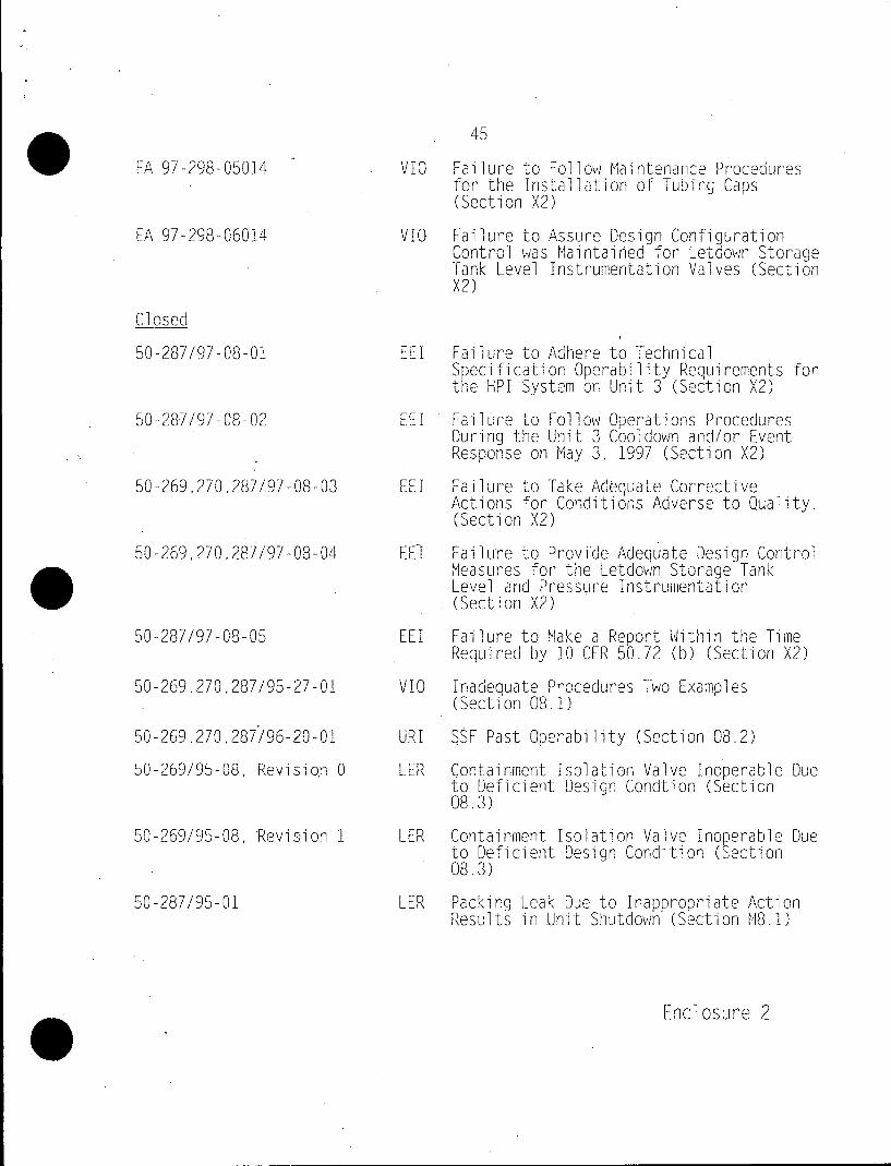
45 . EA 97-298-05014 VIG Failure to Follow Maintenance Procedures for the Installation of Tubing Caps (Section X2)
EA 97-298-06014 VIO Failure to Assure Design Configuration Control was Maintained for Letdown Storage Tank Level Instrumentation Valves (Section X2)
Closed
50-287/97-08-01 EEl Failure to Adhere to Technical Spec ificat ion Operability Requirements for the HPI System on Unit 3 (Section X2)
50-287/97-08-02 EEI Failure to Follow Operations Procedures During the Unit 3 Cooldown and/or Event Response on May 3. 1997 (Section X2)
50-269,270,287/97-08-03 EEl Failure to Take Adequate Corrective Actions for Conditions Adverse to Quality. (Section X2)
50-269,270,287/97-08-04 EEl Failure to Provide Adequate Design Control Measures for, the Letdown Storage Tank, Level and Pressure Instrumentation 0 (Section X2)
50-287/97-08-05 EEI Failure to Make a Report Within the Time Required by 10 CFR 50.72 (b) (Section X2)
50-269.270,287/95-27-01 VID Inadequate Procedures Two Examples (Section 08.1)
50-269,270.287/96-20-01 URI SSF Past Operability (Section 08.2)
50-269/95-08. Revision 0 LER Containment Isolation Valve Inoperable Due to Deficient Design Cond-tion (Section 08.3)
50-269/95-08, Revision 1 LER Containment Isolation Valve Ino erable Due to Deficient Design Condition (ection 08.3)
50-287/95-01 LER Packing Leak Due to Inappropriate Action Results in.Unit Shutdown (Section M8.1)
Enclosure 2
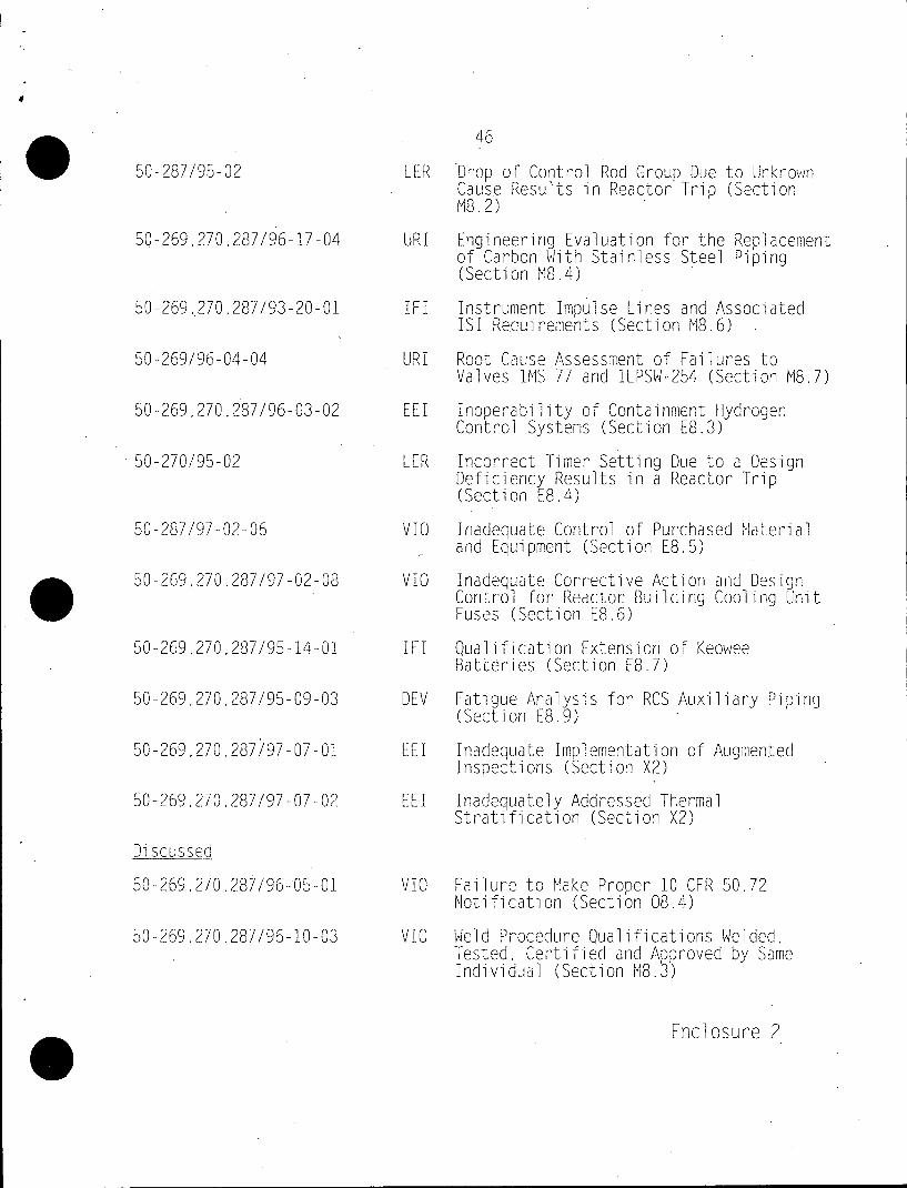
46
50-287/95-02 LER Drop of Control Rod Group Due to Unknown Caus -e Result-LS in Reactor Trip (Section M8.2)
50-269,270,287/96-17-04 URI Engineering Evaluation for the Replacement of Carbon With Stainless Steel Piping (Section M8.4)
50-269,.270,287/93-20-01 IFI Instrument Impulse Lines and Associated ISI Requirements (Section M8.6)
50-269/96-04-04 URI Root Cause Assessment of Failures to Valves 1MS-77 and iLPSW-254 (Section M8.7)
50-269,270,287/96-03-02 El Inoperability of Containment Hydrogen Control Systems (Section E8.3)
50-270/95-02 LER incorrect Timer Setting Due to a Design Deficiency Results in a Reactor Trip (Section E8.4)
50-287/97-02-06 VID inadequate Control of Purchased Material and Equipment (Section E8.5)
50-269,270,287/97-02-08 VID Inadequate Corrective Action and Design Control for Reactor Building Cooling Unit Fuses (Section E8.6)
50-269,270.287/95-14-01 iFI Qualification Extension of Keowee Batteries (Section E8.7)
50-269,270,287/95-09-03 DEV Fatigue Analysis for RCS Auxiliary Piping (Section E8.9)
50-269,270,287/97-07-01 EEl Inadequate Implementation of Augmented inspections (Section X2)
50-269.270,287/97-07-02 EEI Inadequately Addressed Thermal Strati fication (Section X2)
Discussed
50-269,270,287/96-05-01 V/1 Failure to Make Proper 10 CFR 50.72 Notification (Section 08.4)
50-269U270,287/96-10-03 VIO Weld Procedure Qualifications Welded. Tested, Certified and Approved b Same Individl (Section M8.3)
Enclosure 2
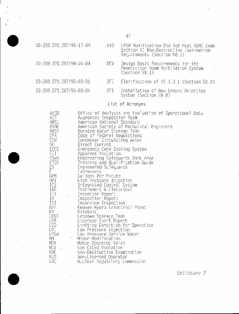
47
50-269.270,287/96-17-09 VIO LPSW Modification Did Not Meet ASME Code Section XI Non-Destructive Examination Requirements (Section M8.5)
50-269,270,287/94-24-04 DEV Design Basis Requirements for the Penetration Room Ventilation System (Section E8.1)
50-269,270,287/95-03-01 IFI Clarification of TS 3.3.1 (Section E8.2)
50-269,270.287/96-03-04 IFI Installation of New Ground Detection System (Section E8.8)
List of Acronyms
AEOD Office of Analysis and Evaluation of Operational Data AIT Augmented Inspection Team ANSI American National Standard ASME Americab Society of Mechanical Engineers BWST Borated Water Storage Tank CFR Code of Federal Regulations CCW Condenser Circulating Water DC Direct Current ECCS Emergency Core Cooling System EE I Apparent Violation ESWA Engineering Safe uards Work Area ETQS Training and Quaiication Guide ES Engineered Safeguards F Fahrenheit GPM Gallons Per Minute HPI High Pressure Injection ICS Integrated Control System I&E Instrument & Electrical IE IFIInspector Report IRInspection Repor ISI Inservice Inspection KHP Keowee Hydro (electric) Plant KV KiloVolt LDST Letdown Storage Tank LER Licensee Event Report LCO Limiting Condition for Operation LPI Low Pressure Injection LPSW Low Pressure Service Water MM Minor Modification MOV Motor Operated Valve NCV Non-Cited Violation NDE Non-Destructive Examination NLO Non-Licensed Operator NRC Nuclear Regulatory Commission
Enclosure 2
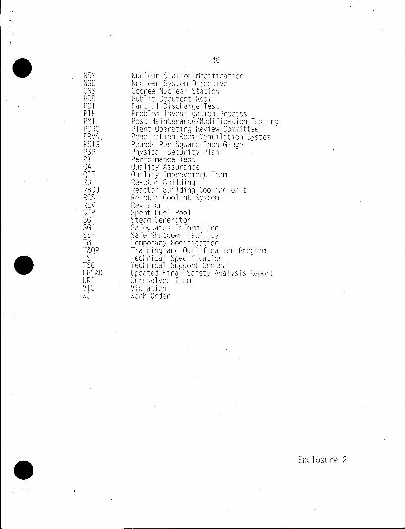
0NSM Nuclear Stati on Mdfcto NSD Nuclear System Directive ONS Oconee Nuclear Station PDR Public Document Room PDT Partial Discharge Test PIP Problem Investigation Process PMT Post Maintenance/Modification Testino 'PORC Plant Operating Review Committee PRVS Penetration Room Ventilation System PSIG Pounds Per Square Inch Gauge PSP Physical Security Plan PT Performance Test QA Quality Assurance QIT Quality improvement Team RB Reactor Building RBCU Reactor Building Cooling Unit RCS Reactor Coolant System REV Revision SFP Spent Fuel Pool SG Steam Generator SGI Safeguards Information SSF Safe Shutdown Facility TM Temporary Modification T&QP Training and Qyalification Program TS Technical Specification TSC Technical SuUSort Center 0 UFSAR Updated FinalV Safety Analysis Report URI Unresolved Item VI Violation
MO Work Order
Enclosure 2