urban highways and streets - illinois department of ... highways and streets can be functionally...
TRANSCRIPT
BUREAU OF DESIGN AND ENVIRONMENT MANUAL
Chapter Forty-eight
URBAN HIGHWAYS AND STREETS (New Construction/Reconstruction)

Illinois URBAN HIGHWAYS AND STREETS September 2010
48-i HARD COPIES UNCONTROLLED
Chapter Forty-eight URBAN HIGHWAYS AND STREETS (New Construction/Reconstruction
Table of Contents
Section Page 48-1 GENERAL ............................................................................................................. 48-1.1
48-1.01 Functional Classification ....................................................................... 48-1.1 48-1.02 Closed and Open Suburban Designations............................................ 48-1.1
48-2 GENERAL DESIGN ELEMENTS ........................................................................... 48-2.1
48-2.01 Design Speed ...................................................................................... 48-2.1 48-2.02 Median Types ...................................................................................... 48-2.1 48-2.03 Typical Sections ................................................................................... 48-2.1 48-2.04 Sidewalks ............................................................................................. 48-2.10 48-2.05 Parking ................................................................................................. 48-2.11
48-3 RAISED-CURB MEDIANS ..................................................................................... 48-3.1
48-3.01 General ................................................................................................ 48-3.1 48-3.02 Four Lanes with Median ....................................................................... 48-3.1 48-3.03 Six Lanes with Median ......................................................................... 48-3.1
48-4 FLUSH OR TRAVERSABLE TYPE MEDIANS ...................................................... 48-4.1
48-4.01 TWLTL Guidelines ............................................................................... 48-4.1 48-4.02 Design Criteria ..................................................................................... 48-4.2
48-4.02(a) Median Width ................................................................ 48-4.2 48-4.02(b) Intersection Treatment .................................................. 48-4.4 48-4.02(c) Curbing ......................................................................... 48-4.4 48-4.02(d) Traversable TWLTL ...................................................... 48-4.4
48-4.03 Railroad Crossings ............................................................................... 48-4.6
48-5 HORIZONTAL ALIGNMENT .................................................................................. 48-5.1
48-5.01 General Application .............................................................................. 48-5.1 48-5.02 General Superelevation Considerations ............................................... 48-5.1 48-5.03 Horizontal Curves ................................................................................. 48-5.3
48-5.03(a) Design Procedures........................................................ 48-5.3 48-5.03(b) Maximum Superelevation Rate ..................................... 48-5.3 48-5.03(c) Minimum Radii .............................................................. 48-5.3 48-5.03(d) Minimum Radii with Retain Normal Crown or
Superelevate at Normal Crown ..................................... 48-5.3
Illinois URBAN HIGHWAYS AND STREETS September 2010
48-ii HARD COPIES UNCONTROLLED
Table of Contents (Continued)
Section Page
48-5.03(e) Superelevated Curves ................................................... 48-5.7 48-5.03(f) Maximum Deflection Without Curve .............................. 48-5.8
48-5.04 Superelevation Development ............................................................... 48-5.8
48-5.04(a) Transition Length .......................................................... 48-5.8 48-5.04(b) Axis of Rotation ............................................................. 48-5.9
48-5.05 Typical Designs .................................................................................... 48-5.10
48-6 TABLES OF DESIGN CRITERIA ........................................................................... 48-6.1 48-7 REFERENCES ...................................................................................................... 48-7.1
Illinois URBAN HIGHWAYS AND STREETS September 2010
48-1.1 HARD COPIES UNCONTROLLED
Chapter Forty-eight URBAN HIGHWAYS AND STREETS (New Construction/Reconstruction)
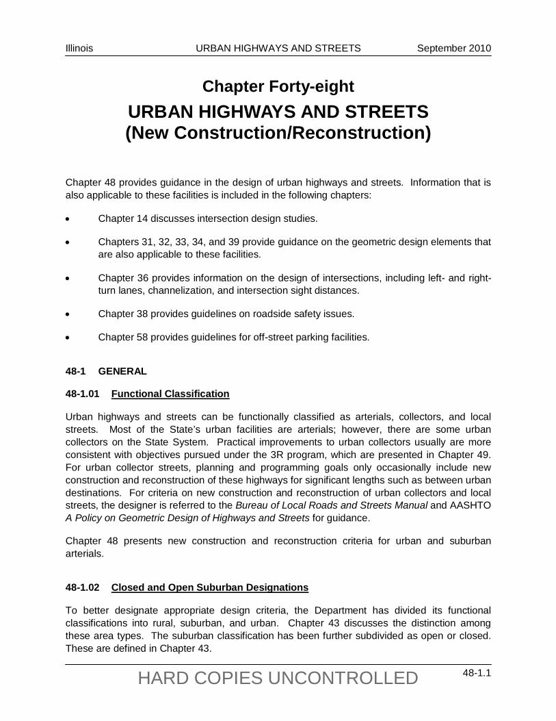
Chapter 48 provides guidance in the design of urban highways and streets. Information that is also applicable to these facilities is included in the following chapters:
• Chapter 14 discusses intersection design studies.
• Chapters 31, 32, 33, 34, and 39 provide guidance on the geometric design elements that are also applicable to these facilities.
• Chapter 36 provides information on the design of intersections, including left- and right-turn lanes, channelization, and intersection sight distances.
• Chapter 38 provides guidelines on roadside safety issues.
• Chapter 58 provides guidelines for off-street parking facilities.
48-1 GENERAL
48-1.01 Functional Classification
Urban highways and streets can be functionally classified as arterials, collectors, and local streets. Most of the State’s urban facilities are arterials; however, there are some urban collectors on the State System. Practical improvements to urban collectors usually are more consistent with objectives pursued under the 3R program, which are presented in Chapter 49. For urban collector streets, planning and programming goals only occasionally include new construction and reconstruction of these highways for significant lengths such as between urban destinations. For criteria on new construction and reconstruction of urban collectors and local streets, the designer is referred to the Bureau of Local Roads and Streets Manual and AASHTO A Policy on Geometric Design of Highways and Streets for guidance.
Chapter 48 presents new construction and reconstruction criteria for urban and suburban arterials.
48-1.02 Closed and Open Suburban Designations
To better designate appropriate design criteria, the Department has divided its functional classifications into rural, suburban, and urban. Chapter 43 discusses the distinction among these area types. The suburban classification has been further subdivided as open or closed. These are defined in Chapter 43.
Illinois URBAN HIGHWAYS AND STREETS September 2010
48-1.2 HARD COPIES UNCONTROLLED
Illinois URBAN HIGHWAYS AND STREETS March 2017
48-2.1 HARD COPIES UNCONTROLLED
48-2 GENERAL DESIGN ELEMENTS
48-2.01 Design Speed
The most common design speed for urban streets is 30 mph (50 km/hr). In relatively undeveloped locations in urban or closed suburban areas and where economics, environmental conditions, and signal spacing permits, consider using a minimum design speed of 40 mph (60 km/hr). Design speeds of 45 mph to 50 mph (70 km/hr to 80 km/hr) are common in open suburban areas.
48-2.02 Median Types
Section 34-3 discusses the various medians that are used in urban and suburban areas and guidelines for selecting medians and widths. In addition, for medians in suburban and urban arterials, the designer should consider the following:
1. Flush/Traversable Medians. These median types may be used in both the urban and suburban areas in conjunction with curb and gutter along the outside edges of the traveled way. For most applications, the flush two-way left-turn lane (TWLTL) should be used. However, in larger metropolitan areas, a traversable TWLTL may be used. Section 48-4 further discusses the use of both types of TWLTL.
2. Depressed Medians. In open suburban areas, a depressed median may be used. This design is typically used with left shoulders and where the design speed is 50 mph (80 km/hr). Section 34-3.03 and Chapter 47 provide further guidance on depressed medians.
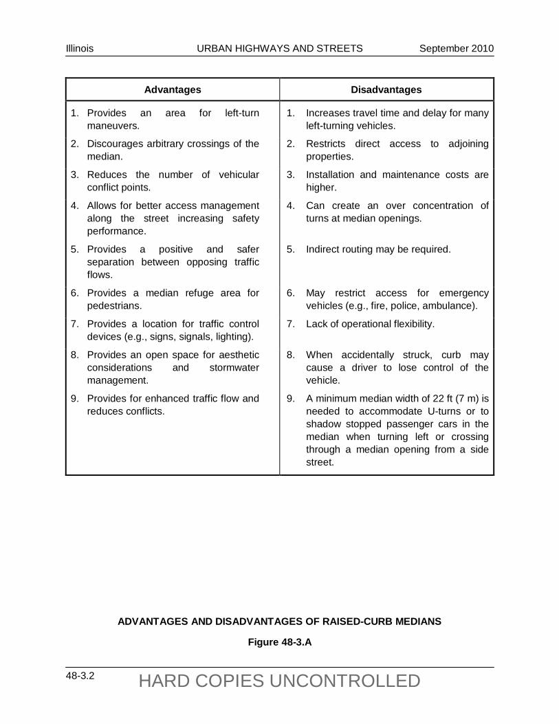
3. Raised-Curb Medians. Usually, a raised-curb median is proposed in suburban and urban areas where managed access to the street and control of left-turn movements are desired. Section 34-3.03 provides guidance on the selection and design of raised-curb medians. Figure 48-3.A discusses the advantages and disadvantages of raised-curb medians as compared to TWLTL medians. Chapter 36 illustrates typical treatments for left-turn lanes within raised-curb medians.
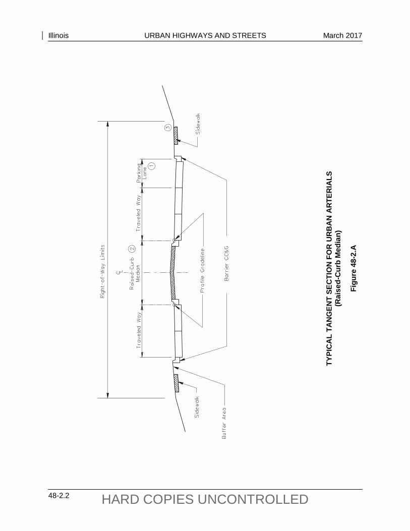
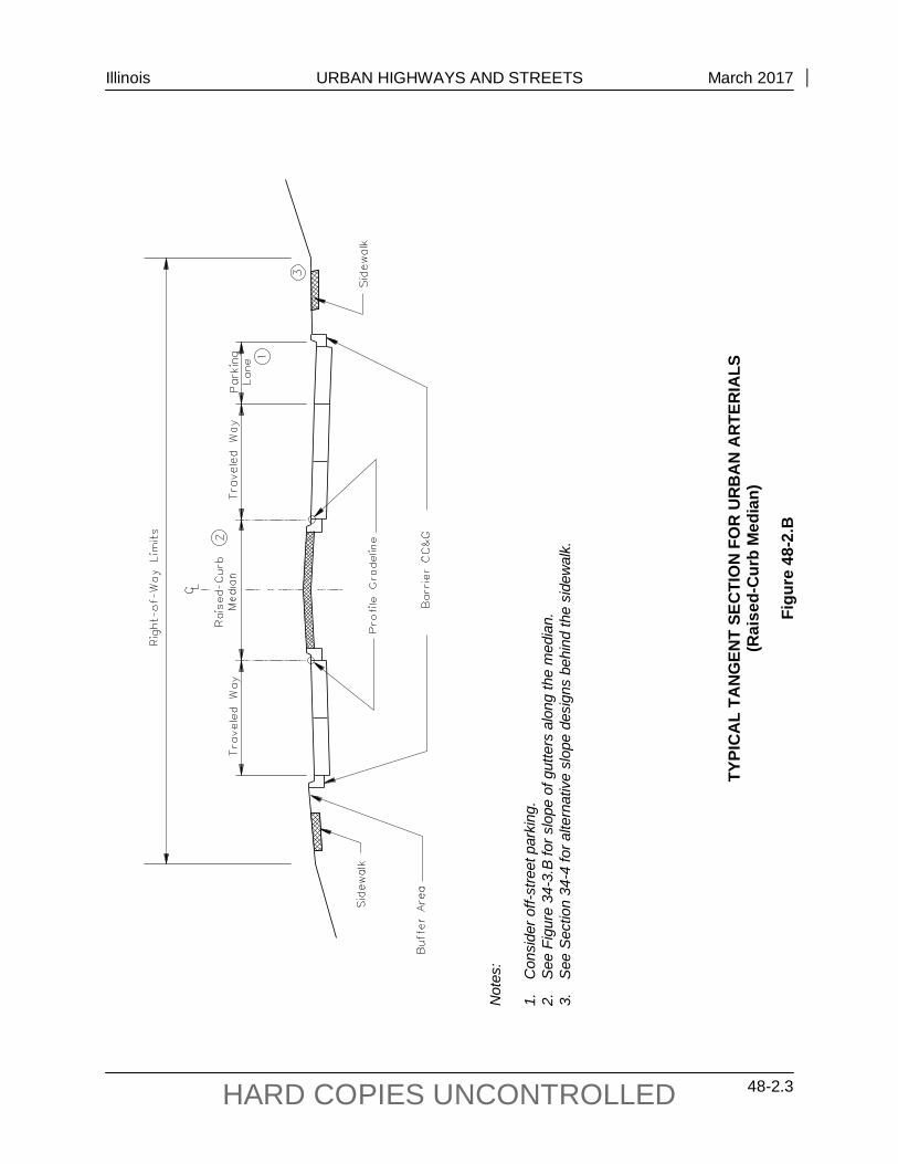
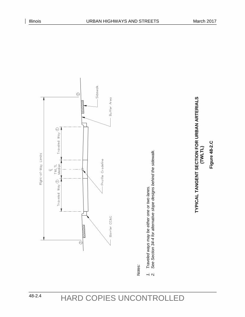
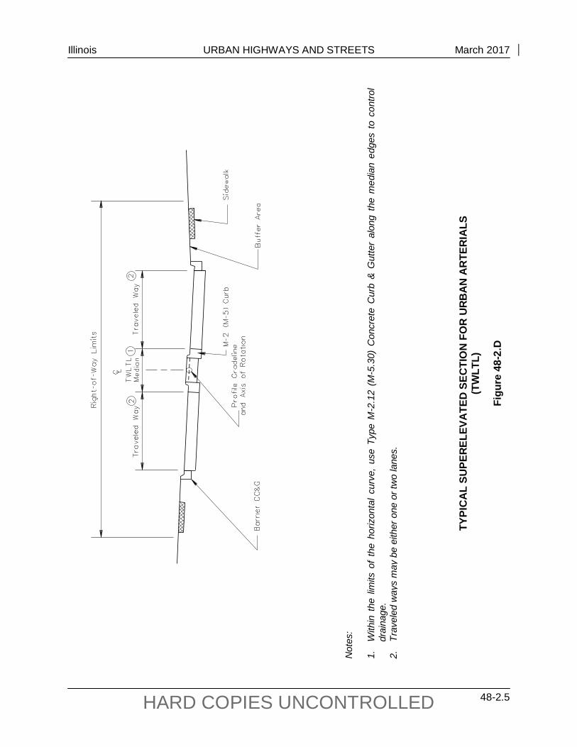
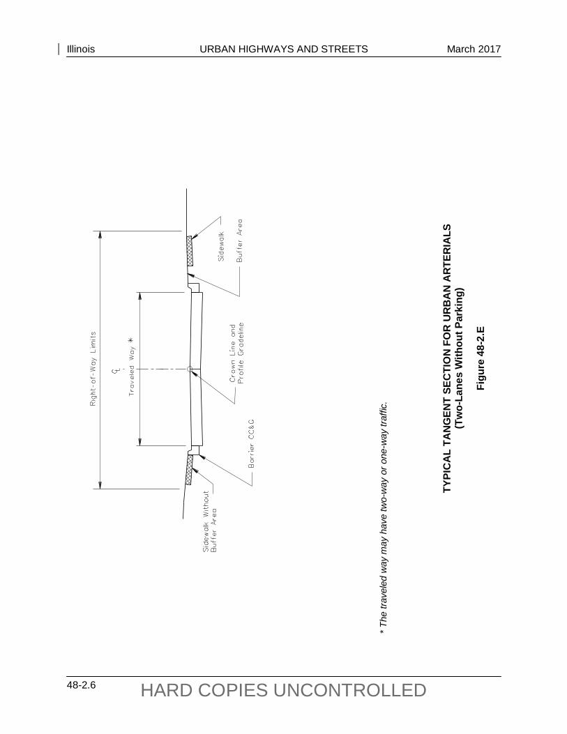
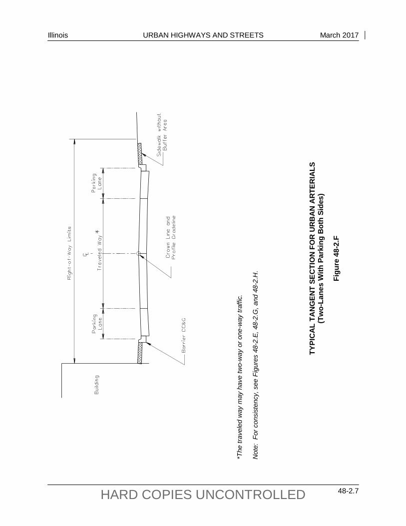
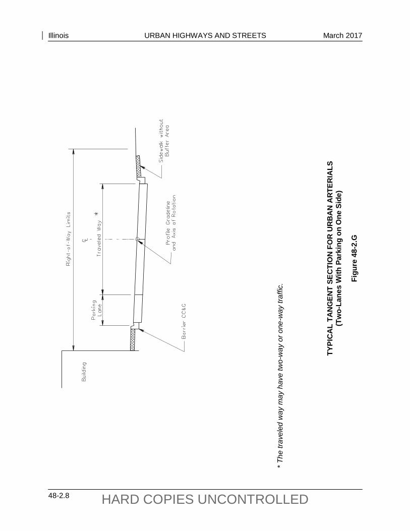
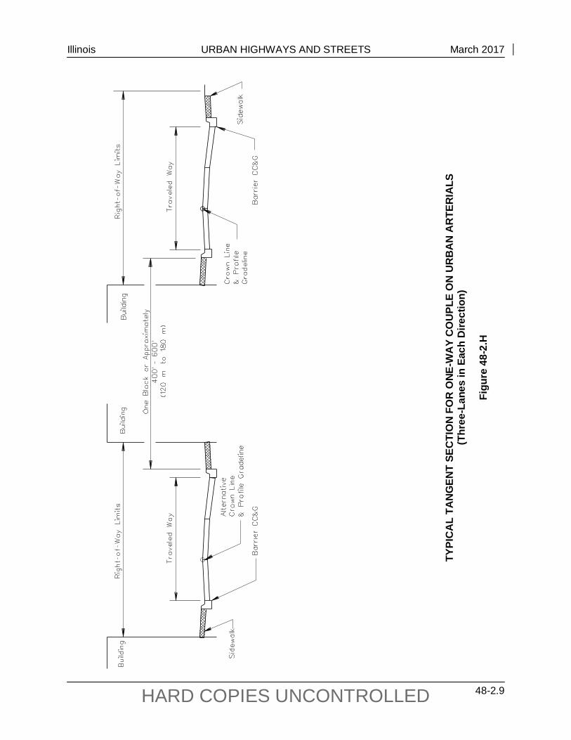
48-2.03 Typical Sections
Figures 48-2.A through 48-2.H present the typical cross sections for the various urban facilities. For a typical six-lane urban arterial with a raised-curb median, see Figure 34-3.B. Give consideration to safe accommodation of pedestrians and bicyclists during the development of the project. Chapter 17 provides detailed guidelines for these issues.
Illinois URBAN HIGHWAYS AND STREETS March 2017
48-2.2 HARD COPIES UNCONTROLLED
TYPI
CA
L TA
NG
ENT
SEC
TIO
N F
OR
UR
BA
N A
RTE
RIA
LS
(Rai
sed-
Cur
b M
edia
n)
Figu
re 4
8-2.
A
Illinois URBAN HIGHWAYS AND STREETS March 2017
48-2.3 HARD COPIES UNCONTROLLED
Not
es:
1.
Con
side
r off-
stre
et p
arki
ng.
2.
See
Fig
ure
34-3
.B fo
r slo
pe o
f gut
ters
alo
ng th
e m
edia
n.
3.
See
Sec
tion
34-4
for a
ltern
ativ
e sl
ope
desi
gns
behi
nd th
e si
dew
alk.
TYPI
CA
L TA
NG
ENT
SEC
TIO
N F
OR
UR
BA
N A
RTE
RIA
LS
(Rai
sed-
Cur
b M
edia
n)
Figu
re 4
8-2.
B
Illinois URBAN HIGHWAYS AND STREETS March 2017
48-2.4 HARD COPIES UNCONTROLLED
Not
es:
1.
Trav
eled
way
s m
ay b
e ei
ther
one
or t
wo
lane
s.
2.
See
Sec
tion
34-4
for a
ltern
ativ
e sl
ope
desi
gns
behi
nd th
e si
dew
alk.
TYPI
CA
L TA
NG
ENT
SEC
TIO
N F
OR
UR
BA
N A
RTE
RIA
LS
(TW
LTL)
Figu
re 4
8-2.
C
Illinois URBAN HIGHWAYS AND STREETS March 2017
48-2.5 HARD COPIES UNCONTROLLED
Not
es:
1.
With
in t
he li
mits
of
the
horiz
onta
l cu
rve,
use
Typ
e M
-2.1
2 (M
-5.3
0) C
oncr
ete
Cur
b &
Gut
ter
alon
g th
e m
edia
n ed
ges
to c
ontro
l dr
aina
ge.
2.
Trav
eled
way
s m
ay b
e ei
ther
one
or t
wo
lane
s.
TYPI
CA
L SU
PER
ELEV
ATE
D S
ECTI
ON
FO
R U
RB
AN
AR
TER
IALS
(T
WLT
L)
Figu
re 4
8-2.
D
Illinois URBAN HIGHWAYS AND STREETS March 2017
48-2.6 HARD COPIES UNCONTROLLED
TYPI
CA
L TA
NG
ENT
SEC
TIO
N F
OR
UR
BA
N A
RTE
RIA
LS
(Tw
o-La
nes
With
out P
arki
ng)
Figu
re 4
8-2.
E
* Th
e tra
vele
d w
ay m
ay h
ave
two-
way
or o
ne-w
ay tr
affic
.
Illinois URBAN HIGHWAYS AND STREETS March 2017
48-2.7 HARD COPIES UNCONTROLLED
*The
trav
eled
way
may
hav
e tw
o-w
ay o
r one
-way
traf
fic.
Not
e: F
or c
onsi
sten
cy, s
ee F
igur
es 4
8-2.
E, 4
8-2.
G, a
nd 4
8-2.
H.
TYPI
CA
L TA
NG
ENT
SEC
TIO
N F
OR
UR
BA
N A
RTE
RIA
LS
(Tw
o-La
nes
With
Par
king
Bot
h Si
des)
Figu
re 4
8-2.
F
Illinois URBAN HIGHWAYS AND STREETS March 2017
48-2.8 HARD COPIES UNCONTROLLED
TYPI
CA
L TA
NG
ENT
SEC
TIO
N F
OR
UR
BA
N A
RTE
RIA
LS
(Tw
o-La
nes
With
Par
king
on
One
Sid
e)
Figu
re 4
8-2.
G
* Th
e tra
vele
d w
ay m
ay h
ave
two-
way
or o
ne-w
ay tr
affic
.
Illinois URBAN HIGHWAYS AND STREETS March 2017
48-2.9 HARD COPIES UNCONTROLLED
TYPI
CA
L TA
NG
ENT
SEC
TIO
N F
OR
ON
E-W
AY
CO
UPL
E O
N U
RB
AN
AR
TER
IALS
(T
hree
-Lan
es in
Eac
h D
irect
ion)
Figu
re 4
8-2.
H
Illinois URBAN HIGHWAYS AND STREETS March 2017
48-2.10 HARD COPIES UNCONTROLLED
48-2.04 Sidewalks
Sidewalks are considered integral parts of the urban environment. In these areas, travelers frequently choose to make their trip on foot, and pedestrians desire to use a paved surface for the trip. When constructing sidewalks, the designer should consider the following:
1. Warrants. In general, if pedestrian activity is anticipated, provide sidewalks along all curbed suburban and urban facilities. Extend all sidewalks to logical termini. If sidewalks are not provided in the initial design, grading should be completed so that sidewalks can be added in the future. If sidewalks will not be installed, the designer should confer with local officials to ensure that sidewalks are not required or desired.
New sidewalks or sidewalks replaced because of deterioration that meet these warrants, will only be constructed if the local agency is willing to participate financially and assume the maintenance responsibility for the sidewalk in accordance with the criteria in Chapter 5.
2. Widths. A typical sidewalk is 5 ft (1.5 m) wide. If no buffer area is provided, the sidewalk should be 7 ft (2.0 m) wide to accommodate any appurtenances that may be included in the sidewalk; see Item #4 below. High pedestrian volumes may warrant greater widths in business areas and school zones. In these cases, a detailed capacity analysis may be required to determine the sidewalk width. Use the Highway Capacity Manual for this analysis.
3. Buffer Areas. If the available right-of-way is sufficient, provide a buffer area between the back of curb and sidewalk. These areas provide space for snow storage, utilities, and allow a greater separation between vehicles and pedestrians. The buffer area should be 2 ft to 3 ft (600 mm to 900 mm) wide to be effective and wider if practical. Buffer areas may also be used for the placement of roadside appurtenances.
4. Appurtenances. Where a buffer area cannot be provided, the designer must consider the impact of roadside appurtenances within the sidewalk (e.g., mailboxes, fire hydrants, parking meters, utility poles) as these elements typically reduce the usable width of the sidewalk and interfere with pedestrian activity. Typically, a 1 ft (300 mm) minimum width is provided between the sidewalk and right-of-way line. Utility poles usually can be located behind the sidewalk in this area providing a clear sidewalk width.
5. CBD Areas. In central business districts, the entire area between the back of curb and the front of buildings is fully paved as a sidewalk.
6. Accessibility. The design of the sidewalk (e.g., sidewalk width, cross slope, longitudinal grade, curb ramps) along public rights-of-way must meet the ADA criteria presented in Chapter 58.
7. Bridges. In general, if there is or expected to be pedestrian activity across a bridge, include sidewalks on both sides of the bridge. On long bridges, it may be more cost effective to provide a single sidewalk on one side. However, a safe crossing must be
Illinois URBAN HIGHWAYS AND STREETS March 2017
48-2.11 HARD COPIES UNCONTROLLED
provided in advance of the bridge if there is evidence of pedestrian activity on both sides of the roadway. See Chapter 39 for typical sections.
48-2.05 Parking
For most urban projects, the designer must evaluate the demand for parking. Desirably, these parking needs will be accommodated by providing off-street parking facilities. Chapter 58 provides information on the design and layout of off-street parking facilities. When providing on-street parking along urban streets, the designer should evaluate the following:
1. Warrants. Do not introduce any new parking lanes along State highways. On-street parking reduces capacity, impedes traffic flow, and may produce undesirable traffic operations or may increase the crash potential. On State reconstruction projects, consider removing parking lanes. Removal of existing or revising existing on-street parking configurations will require coordination and concurrence with local officials and adjacent businesses. Chapter 58 discusses the procedures and guidelines for replacing on-street parking with off-street parking.
2. Local Agreements. Prior to implementation of parking on a project, the State will enter into a joint agreement with the municipality; see Chapter 5. The municipality will be required to maintain the parking lane and adopt and enforce an appropriate parking ordinance or provide copies of an existing ordinance in effect. Attach the ordinance to the joint improvement agreement as an exhibit and make a part thereof prior to execution of the agreement on behalf of the State. Enforcement of the ordinance is understood to include erection and maintenance of any necessary NO PARKING or PARALLEL PARKING ONLY signs.
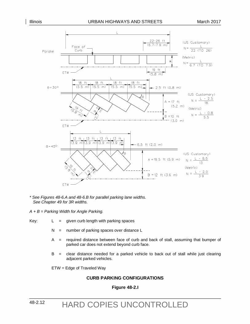
3. Configurations. There are two basic types of on-street parking parallel and angle parking. These are illustrated in Figure 48-2.I.
4. Design Considerations.
a. Department Authority. The Illinois Vehicle Code authorizes the Department to determine the propriety of diagonal parking upon routes under its jurisdiction. Section 11-1304(c) of the Code states:
Local authorities may permit angle parking on any roadway, except that angle parking shall not be permitted on any federal-aid or state highway unless the Department has determined the roadway is of sufficient width to permit angle parking without interfering with the free movement of traffic.
b. Capacity. Parallel parking is the preferred arrangement where street space is
limited and traffic capacity is a major factor. Where angle parking is provided, the overall level of service for the facility preferably should be not less than C.
Illinois URBAN HIGHWAYS AND STREETS March 2017
48-2.12 HARD COPIES UNCONTROLLED
* See Figures 48-6.A and 48-6.B for parallel parking lane widths. See Chapter 49 for 3R widths. A + B = Parking Width for Angle Parking. Key: L = given curb length with parking spaces N = number of parking spaces over distance L A = required distance between face of curb and back of stall, assuming that bumper of
parked car does not extend beyond curb face. B = clear distance needed for a parked vehicle to back out of stall while just clearing
adjacent parked vehicles. ETW = Edge of Traveled Way
CURB PARKING CONFIGURATIONS
Figure 48-2.I
Illinois URBAN HIGHWAYS AND STREETS March 2017
48-2.13 HARD COPIES UNCONTROLLED
c. Number of Spaces. Angle parking provides more spaces per linear foot (meter) than parallel parking, but requires a greater cross street width.
d. Angle. Angle parking should be 45° or less.
e. Backing Maneuver. Angle parking requires the driver to back into the traveled way when sight distance may be restricted by adjacent parked vehicles. This maneuver may surprise an approaching motorist. As indicated in Figure 48-2.I, the parked car will require a certain distance “B” to back out of its stall. Whether or not this is a reasonably safe maneuver will depend upon the number of lanes in each direction, lane widths, operating speeds, traffic volumes during peak hours, parking demand, and turnover rate of parked vehicles.
f. Crashes. After analyzing backing maneuver space, angle parking may be considered to remain if there is no history of crashes relating to the existing angle parking.
g. Trucks. If the truck traffic on the facility is 10% or more of the ADT, angle parking should be removed.
h. Agreement. The agreement with local officials must include provisions for monitoring and maintaining the angle parking after the project is completed to determine if safety or capacity problems develop as traffic volumes increase.
5. Stall Dimensions. Figure 48-2.I provides the width and length criteria for parking stalls of various configurations. The figure also indicates the number of stalls that can be provided for each parking configuration for a given curb length. The surface widths in Figures 48-6.A and 48-6.B assume parallel parking on one or both sides of the street.
6. ADA Requirements. Chapter 58 presents the accessibility requirements for on-street parking for persons with disabilities.
7. Location. When locating parking spaces, the designer should consider the following:
• Parking is prohibited within 20 ft (6.1 m) of any crosswalk.
• Prohibit parking within 10 ft to 16 ft (3 m to 5 m) of the beginning of the curb radius at mid-block driveway entrances.
• Parking is prohibited within 50 ft (15.2 m) of the nearest rail of a highway/railroad crossing.
• Parking is prohibited within 15 ft (4.6 m) of a fire hydrant.
• Parking is prohibited within 30 ft (9.1 m) on the approach leg to any intersection with a flashing beacon, stop sign, or traffic control signal.
• Parking is prohibited on bridges or within a highway tunnel.
Illinois URBAN HIGHWAYS AND STREETS March 2017
48-2.14 HARD COPIES UNCONTROLLED
• Prohibit parking from areas designated by local traffic and enforcement regulations (e.g., near school zones, loading zones, bus stops). See local ordinances for additional information on parking restrictions.
• Check intersection sight distance to side roads.
• Eliminate parking across from a T intersection.

Illinois URBAN HIGHWAYS AND STREETS September 2010
48-3.1 HARD COPIES UNCONTROLLED
48-3 RAISED-CURB MEDIANS
48-3.01 General
Figure 48-3.A presents advantages and disadvantages of raised-curb medians as compared to TWLTL medians. Section 34-3.03 provides guidance on the selection and design of raised-curb medians.
48-3.02 Four Lanes with Median
The most common typical section with raised-curb medians is two lanes in each direction separated by the curbed median; see Figures 48-2.A and 48-2.B.
48-3.03 Six Lanes with Median
Where traffic volumes indicate a need for three lanes in each direction, the recommended median design is a raised-curb. See Figure 34-3.B for a typical cross section design. Where there is a need for dual left turns, the minimum width of the median is 30 ft (9.5 m). Where major intersections are closely spaced and there is a need for dual lefts at most intersections, provide the 30 ft (9.5 m) median width along the entire street.
Where a five-lane facility exists and traffic volumes (ADT > 40,000) and/or capacity analysis warrants a six-lane design, consider providing a traversable type median with M-2 (M-5) curb. Prior to incorporating the M-2 (M-5) curb median into the design, evaluate the following:
1. Concentrated Left-Turn Movements. With raised-curb medians, left-turn movements are concentrated at the intersections, thereby reducing the overall conflict areas of the facility. However, drivers are forced to make all left turns at the intersections, which may overload the capacity of the intersections, increase driver travel time, and may create the need for U-turns at intersections.
2. Businesses. Business owners may perceive an adverse effect when a raised-curb median is proposed. See NCHRP 395 Capacity and Operations Effects of Midblock Left-Turn Lanes for guidance on the effects of curbed medians.
3. Opposing Gaps. Six-lane facilities contain high-traffic volumes that limit opportunities for left-turns across the opposing traffic. NCHRP 395 discusses the consequences of these movements on the facility.
4. Merging Gaps. Entering a six-lane facility with an M-2 (M-5) curbed median from a non-signalized side access point provides a considerable challenge for the driver. Upwards of nine different movements may need to be observed by the driver at any given time. Where M-2 (M-5) curbed facilities are justified, the TWLTL can be used as a waiting area before a gap occurs and a merge can take place. For additional concerns, see NCHRP 330 Effective Utilization of Street Width on Urban Arterials.
Illinois URBAN HIGHWAYS AND STREETS September 2010
48-3.2 HARD COPIES UNCONTROLLED
Advantages Disadvantages
1. Provides an area for left-turn maneuvers.
1. Increases travel time and delay for many left-turning vehicles.
2. Discourages arbitrary crossings of the median.
2. Restricts direct access to adjoining properties.
3. Reduces the number of vehicular conflict points.
3. Installation and maintenance costs are higher.
4. Allows for better access management along the street increasing safety performance.
4. Can create an over concentration of turns at median openings.
5. Provides a positive and safer separation between opposing traffic flows.
5. Indirect routing may be required.
6. Provides a median refuge area for pedestrians.
6. May restrict access for emergency vehicles (e.g., fire, police, ambulance).
7. Provides a location for traffic control devices (e.g., signs, signals, lighting).
7. Lack of operational flexibility.
8. Provides an open space for aesthetic considerations and stormwater management.
8. When accidentally struck, curb may cause a driver to lose control of the vehicle.
9. Provides for enhanced traffic flow and reduces conflicts.
9. A minimum median width of 22 ft (7 m) is needed to accommodate U-turns or to shadow stopped passenger cars in the median when turning left or crossing through a median opening from a side street.
ADVANTAGES AND DISADVANTAGES OF RAISED-CURB MEDIANS
Figure 48-3.A
Illinois URBAN HIGHWAYS AND STREETS October 2015
48-4.1 HARD COPIES UNCONTROLLED
48-4 FLUSH OR TRAVERSABLE TYPE MEDIANS
48-4.01 Two Way Left Turn Lane Guidelines
The applicability of a two-way left-turn lane (TWLTL) is a function of the traffic conditions that result from the adjacent land use. Evaluate the area to determine the relative attractiveness of a flush median as compared to a raised-curb median. For example, a TWLTL may perpetuate more strip development. When this is not desirable, use a raised-curb median. For additional information on the use of a TWLTL design or flush alternating left-turn lanes along a street, see NCHRP 395 Capacity and Operational Effects of Midblock Left-Turn Lanes and Figures 34-3.C and 34-3.D. Also consider the following guidelines:
1. General. Only provide TWLTL in:
• areas with a high number of existing driveways per mile (km) (e.g., 30-60 driveways total per mile (20-40 driveways total per km) on both sides of street);
• areas of existing high-density commercial development;
• areas with substantial mid-block left turns; and/or
• areas where space is not available for raised-curb median widths and a need for left-turn lanes exists.
2. Highway Type. Two-lane and four-lane undivided urban or suburban arterials are the most common candidates for the implementation of a TWLTL design. Once these streets are reconstructed, they are commonly referred to as three-lane and five-lane facilities, respectively.
3. Traffic Volumes. Traffic volumes and the percent of left turns in each direction are a significant factor in the consideration of a TWLTL. Use a 20-year design for traffic volumes. As general guidance, consider the following:
a. Two-Lane Facilities. On existing two-lane roadways, a TWLTL design will often be advantageous for traffic volumes between 5,000 and 14,000 ADT.
b. Four-Lane Facilities. On existing four-lane undivided highways, a TWLTL will often be advantageous for traffic volumes between 10,000 and 40,000 ADT. The 40,000 ADT value assumes left-turn percentages less than or equal to 30%.
c. Six-Lane Facilities. The decision on whether to provide a TWLTL or a raised-curb median will be determined on a case-by-case basis. See Section 48-3.03 for guidance.
d. Pedestrians. Pedestrian crossing volumes are also a consideration because of the large paved area that must be traversed when a TWLTL is present (i.e., no pedestrian refuge exists). There may be significant delays for vehicles at signalized intersections to accommodate pedestrians having to cross the
Illinois URBAN HIGHWAYS AND STREETS October 2015
48-4.2 HARD COPIES UNCONTROLLED
highway in one movement. A raised-curb median may provide a refuge area for pedestrians to cross the highway in two movements.
4. Speed. The design speed of an urban street is a major factor in TWLTL applications. Experience indicates that design speeds from 25 mph to 45 mph (40 km/hr to 70 km/hr) will properly accommodate TWLTL operations. For design speeds higher than 45 mph (70 km/hr), the use of TWLTL is not recommended.
5. Crash History. On urban or suburban arterials without medians, traffic conflicts often result because of a significant number of mid-block left turns combined with significant opposing traffic volumes. This may lead to a disproportionate number of mid-block, rear-end, and/or sideswipe crashes. The inclusion of a median for left turns is likely to reduce these types of crashes. Review and evaluate the available crash data to determine if disproportionately high numbers of these crashes are occurring.
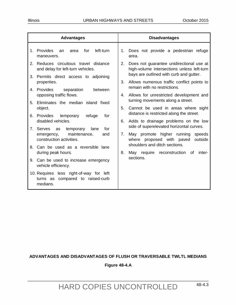
6. Advantages and Disadvantages. Figure 48-4.A summarizes some of the advantages and disadvantages of a TWLTL median design.
48-4.02 Design Criteria
48-4.02(a) Median Width
Existing highways that warrant the installation of a TWLTL are often located in areas of restricted right-of-way, and conversion of the existing cross section may be difficult. To obtain the TWLTL width, the designer may have to consider the following:
• reducing the width of existing through lanes and analyzing side road radius returns,
• eliminating existing parking lanes and reconstructing curb and gutter and sidewalks,
• eliminating existing shoulders and ditches,
• eliminating existing buffer areas behind curbs and reconstructing curb and gutter and existing sidewalks,
• acquiring additional right-of-way to expand the pavement width by the amount needed for the TWLTL and sidewalks, and/or
• removing an existing raised-curb median.
See Sections 34-3.03 and 34-3.04 for further guidance on medians.
Illinois URBAN HIGHWAYS AND STREETS October 2015
48-4.3 HARD COPIES UNCONTROLLED
Advantages
Disadvantages
1. Provides an area for left-turn
maneuvers.
2. Reduces circuitous travel distance and delay for left-turn vehicles.
3. Permits direct access to adjoining properties.
4. Provides separation between opposing traffic flows.
5. Eliminates the median island fixed object.
6. Provides temporary refuge for disabled vehicles.
7. Serves as temporary lane for emergency, maintenance, and construction activities.
8. Can be used as a reversible lane during peak hours.
9. Can be used to increase emergency vehicle efficiency.
10. Requires less right-of-way for left turns as compared to raised-curb medians.
1. Does not provide a pedestrian refuge
area.
2. Does not guarantee unidirectional use at high-volume intersections unless left-turn bays are outlined with curb and gutter.
3. Allows numerous traffic conflict points to remain with no restrictions.
4. Allows for unrestricted development and turning movements along a street.
5. Cannot be used in areas where sight distance is restricted along the street.
6. Adds to drainage problems on the low side of superelevated horizontal curves.
7. May promote higher running speeds where proposed with paved outside shoulders and ditch sections.
8. May require reconstruction of inter-sections.
ADVANTAGES AND DISADVANTAGES OF FLUSH OR TRAVERSABLE TWLTL MEDIANS
Figure 48-4.A
Illinois URBAN HIGHWAYS AND STREETS October 2015
48-4.4 HARD COPIES UNCONTROLLED
48-4.02(b) Intersection Treatment
At intersections with public roads, consider the following:
1. Side Streets/Major Entrances. At intersections, convert the TWLTL to an exclusive left-turn lane and omit the pavement markings through the intersection. However, where turning volumes to minor streets are low, it will not be necessary to convert the TWLTL markings to an exclusive left-turn lane.
2. Turning Volumes. The left-turn demand into intersecting side streets is a factor in determining the appropriate length of the left-turn lane. As a general rule in urban areas, the minimum storage length will govern the length of left-turn lanes; see Section 36-3.02.
3. Minimum Length of TWLTL. The TWLTL should have sufficient length to operate properly, and the type of intersection treatments will determine the length of the TWLTL. Typically, the minimum length will be 650 ft to 1000 ft (200 m to 300 m) (one block long). The final decision on the length of the TWLTL will be based on site conditions.
4. Operational/Safety Factors. Provide proper signing and stopping sight distance at the beginning and end of each TWLTL. Where a number of turning movements are expected into and out of entrances located close to a major intersection, it is desirable to design a raised-curb median (M-6 (M-15)) into the segment of the exclusive left-turn lane; see Figure 34-3.D.
48-4.02(c) Curbing
In urban and suburban areas where a TWLTL is used, provide curb and gutter along the outside edges of the traveled way.
48-4.02(d) Traversable TWLTL
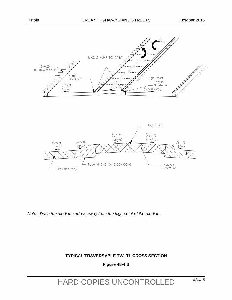
On most highways and streets, the TWLTL will be a flush design with the adjacent travel lanes. See Figures 34-3.D and 48-2.C. Where traffic volumes and mid-block left turns are unusually high, a traversable TWLTL median with a Type M-2.12 (M-5.30) Concrete Curb and Gutter may be a more appropriate design option. Figure 48-4.B illustrates the typical design for a traversable TWLTL. The M-2 (M-5) curb is used to delineate the edges of the TWLTL and traffic is allowed to turn left across the median. Also, where a horizontal curve with superelevation is proposed along a street with a flush TWLTL, use the Type M2.12 (M-5.30) Concrete Curb and Gutter along the median edges of the curve to improve drainage; see Figure 48-2.D.
Illinois URBAN HIGHWAYS AND STREETS October 2015
48-4.5 HARD COPIES UNCONTROLLED
Note: Drain the median surface away from the high point of the median.
TYPICAL TRAVERSABLE TWLTL CROSS SECTION
Figure 48-4.B
Illinois URBAN HIGHWAYS AND STREETS October 2015
48-4.6 HARD COPIES UNCONTROLLED
48-4.03 Railroad Crossings
TWLTLs are not extended across a highway/railroad grade crossing. Terminate the TWLTL 150 ft to 200 ft (45 m to 60 m) in advance of the crossing and provide a raised-curb median adjacent to the railroad; see Figure 7-3.E. In addition, the designer should coordinate the design with the Bureau of Operations.
Illinois URBAN HIGHWAYS AND STREETS February 2016
48-5.1 HARD COPIES UNCONTROLLED
48-5 HORIZONTAL ALIGNMENT
48-5.01 General Application
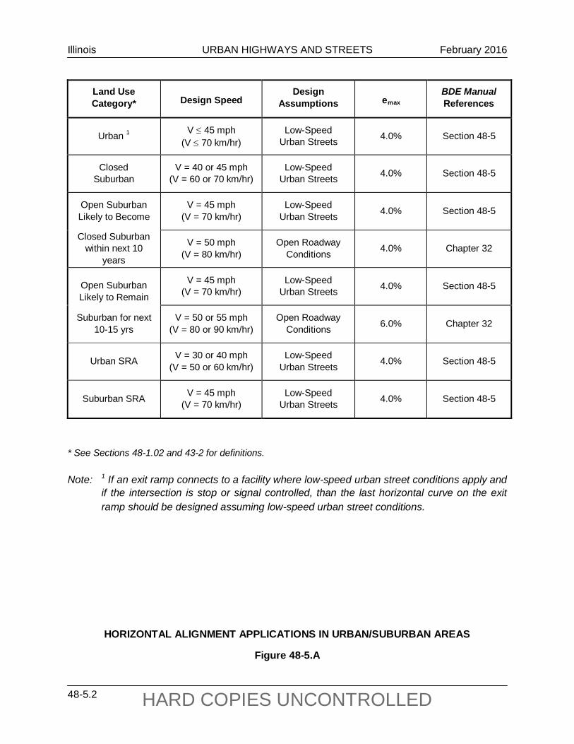
For urban and suburban streets and highways, the application of horizontal alignment criteria will depend on several factors. Figure 48-5.A summarizes the application of horizontal alignment criteria to urban facilities. The remainder of Section 48-5 specifically discusses the application to low-speed urban streets (V ≤ 45 mph (70 km/hr)).
48-5.02 General Superelevation Considerations
For low-speed urban streets, the operational conditions and physical constraints are significantly different than those on rural highways and high-speed urban highways. The following lists some of the characteristics of low-speed urban streets that often complicate superelevation development:
1. Roadside Development/Intersections/Driveways. Built-up roadside development is common adjacent to low-speed urban streets. Matching superelevated curves with many driveways, intersections, sidewalks, etc., creates considerable complications. For example, this may require reconstructing the profile on side streets, and re-grading parking lots, lawns, etc., to compensate for the higher elevation on the high side of the superelevated curve.
2. Non-Uniform Travel Speeds. On low-speed urban streets, travel speeds are often non-uniform because of frequent signalization, stop signs, vehicular conflicts, etc. It is undesirable for traffic to stop on a superelevated curve, especially when snow or ice is present.
3. Limited Right-of-Way. Superelevated curves often result in more right-of-way impacts than would otherwise be necessary. Right-of-way is often restricted along low-speed urban streets.
4. Wide Pavement Areas. Many low-speed urban streets have wide pavement areas because of the number of traffic lanes, the use of a flush-type median, or the presence of parking lanes. In general, the wider the pavement area, the more complicated is the development of superelevation.
5. Surface Drainage. Proper cross slope drainage on low-speed urban streets can be difficult even on sections with a normal crown. The minimum longitudinal gradient on a street with curb and gutter is 0.30%. A curve with superelevation (or remove crown) and/or where a flush-type median is proposed introduces another complicating factor unless special features are designed into the median. See Figure 48-2.D, which illustrates the use of Type M-2.12 (M-5.30) Concrete Curb and Gutter to control drainage.
Illinois URBAN HIGHWAYS AND STREETS February 2016
48-5.2 HARD COPIES UNCONTROLLED
Land Use Category* Design Speed
Design Assumptions emax
BDE Manual References
Urban 1 V ≤ 45 mph (V ≤ 70 km/hr)
Low-Speed Urban Streets 4.0% Section 48-5
Closed Suburban
V = 40 or 45 mph (V = 60 or 70 km/hr)
Low-Speed Urban Streets 4.0% Section 48-5
Open Suburban Likely to Become
V = 45 mph (V = 70 km/hr)
Low-Speed Urban Streets 4.0% Section 48-5
Closed Suburban within next 10
years
V = 50 mph (V = 80 km/hr)
Open Roadway Conditions 4.0% Chapter 32
Open Suburban Likely to Remain
V = 45 mph (V = 70 km/hr)
Low-Speed Urban Streets 4.0% Section 48-5
Suburban for next 10-15 yrs
V = 50 or 55 mph (V = 80 or 90 km/hr)
Open Roadway Conditions 6.0% Chapter 32
Urban SRA V = 30 or 40 mph (V = 50 or 60 km/hr)
Low-Speed Urban Streets 4.0% Section 48-5
Suburban SRA V = 45 mph (V = 70 km/hr)
Low-Speed Urban Streets 4.0% Section 48-5
* See Sections 48-1.02 and 43-2 for definitions. Note: 1 If an exit ramp connects to a facility where low-speed urban street conditions apply and
if the intersection is stop or signal controlled, than the last horizontal curve on the exit ramp should be designed assuming low-speed urban street conditions.
HORIZONTAL ALIGNMENT APPLICATIONS IN URBAN/SUBURBAN AREAS
Figure 48-5.A
Illinois URBAN HIGHWAYS AND STREETS February 2016
48-5.3 HARD COPIES UNCONTROLLED
48-5.03 Horizontal Curves
48-5.03(a) Design Procedures
Because of the unique operational conditions for low-speed urban streets, it is appropriate to use a modified theoretical basis for horizontal alignment criteria when compared to open-roadway conditions. Specifically, the use of AASHTO Method 2 to distribute superelevation and side friction. This Method assumes maximum design side friction is used before any superelevation is introduced. The practical benefit is that most horizontal curves can be designed with little or no superelevation on low-speed urban streets when compared to the criteria for open roadway conditions in Chapter 32. See the AASHTO publication A Policy on Geometric Design of Highways and Streets for a further discussion on Method 2.
48-5.03(b) Maximum Superelevation Rate
For new construction projects, use emax = 4.0% for low-speed urban streets. For urban reconstruction projects, existing horizontal curves can remain in place with a superelevation rate up to 6%. However, the use of 6% on a low-speed urban street is a Level Two design exception as discussed in Section 31-7. See Section 36-1.05(b) for a discussion on superelevation for intersections on curves.
48-5.03(c) Minimum Radii
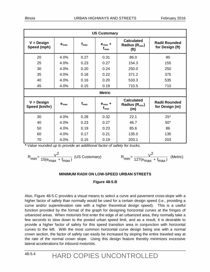
Figure 48-5.B presents the minimum radii for various design speeds for low-speed urban streets. These values should only be used where highly restricted right-of-way conditions exist.
48-5.03(d) Minimum Radii with Retain Normal Crown or Superelevate at Normal Crown
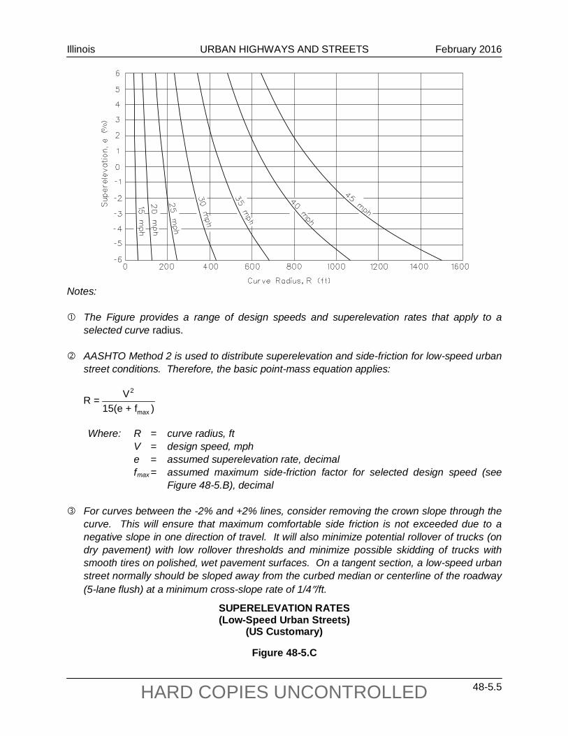
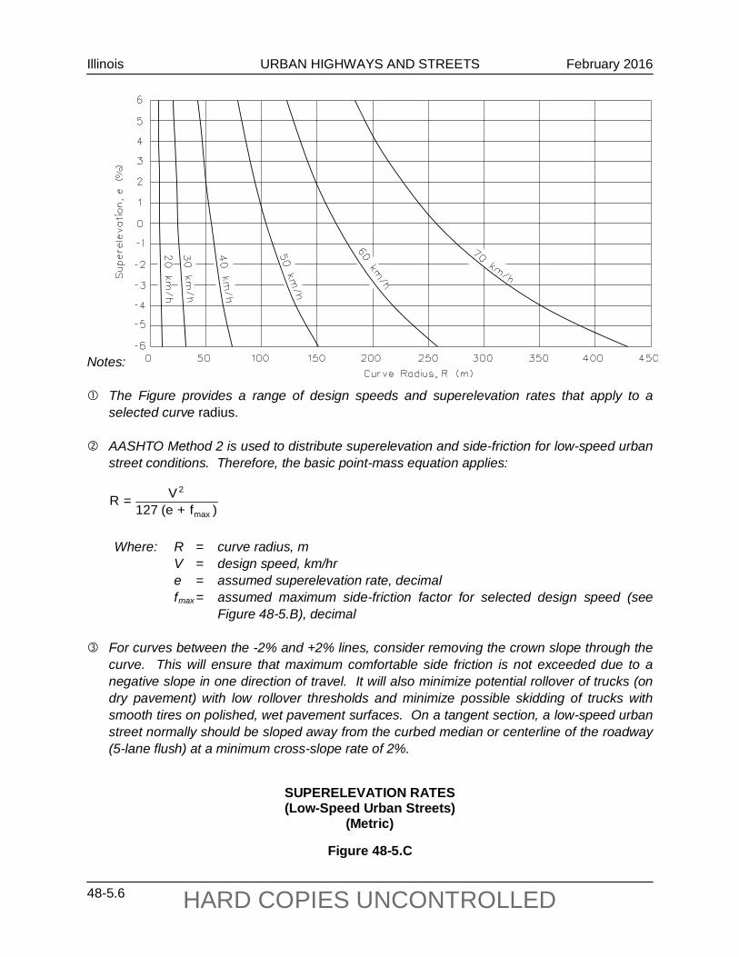
In urban areas, restricted right-of-way conditions usually exist. The radii for superelevation rates of -6% to +6% are shown in Figure 48-5.C. The -2% line provides the minimum curve radii for which a normal crown of ¼ in/ft (2%) should be retained. For radii and design speeds between the -2% line and +2% line, provide a superelevation of 2.0%. For radii and design speeds above the +2% line, superelevate at the indicated rate.
Illinois URBAN HIGHWAYS AND STREETS February 2016
48-5.4 HARD COPIES UNCONTROLLED
)maxf+max15(e2V=minR
US Customary
V = Design Speed (mph)
emax
fmax
emax +
fmax
Calculated Radius (Rmin)
(ft)
Radii Rounded for Design (ft)
20 25 30 35 40 45
4.0% 4.0% 4.0% 4.0% 4.0% 4.0%
0.27 0.23 0.20 0.18 0.16 0.15
0.31 0.27 0.24 0.22 0.20 0.19
86.0 154.3 250.0 371.2 533.3 710.5
90 155 250 375 535 710
Metric
V = Design Speed (km/hr)
emax
fmax
emax +
fmax
Calculated Radius (Rmin)
(m)
Radii Rounded for Design (m)
30 40 50 60 70
4.0% 4.0% 4.0% 4.0% 4.0%
0.28 0.23 0.19 0.17 0.15
0.32 0.27 0.23 0.21 0.19
22.1 46.7 85.6
135.0 203.1
25* 50* 86
135 203
* Value rounded up to provide an additional factor of safety for trucks.
(US Customary) (Metric)
MINIMUM RADII ON LOW-SPEED URBAN STREETS
Figure 48-5.B Also, Figure 48-5.C provides a visual means to select a curve and pavement cross-slope with a higher factor of safety than normally would be used for a certain design speed (i.e., providing a curve and/or superelevation rate with a higher theoretical design speed). This is a useful function provided by the format of the graph for designing horizontal curves at the fringes of urbanized areas. When motorists first enter the edge of an urbanized area, they normally take a few seconds to slow down to the posted urban speed limit, and as a result, it is desirable to provide a higher factor of safety for this speed transition area in conjunction with horizontal curves to the left. With the most common horizontal curve design being one with a normal crown section, the factor of safety can easily be increased by sloping the entire traveled way at the rate of the normal crown slope. Using this design feature thereby minimizes excessive lateral accelerations for inbound motorists.
)maxf+max127(e2V=minR
Illinois URBAN HIGHWAYS AND STREETS February 2016
48-5.5 HARD COPIES UNCONTROLLED
Notes: The Figure provides a range of design speeds and superelevation rates that apply to a
selected curve radius. AASHTO Method 2 is used to distribute superelevation and side-friction for low-speed urban
street conditions. Therefore, the basic point-mass equation applies:
Where: R = curve radius, ft V = design speed, mph e = assumed superelevation rate, decimal fmax = assumed maximum side-friction factor for selected design speed (see
Figure 48-5.B), decimal For curves between the -2% and +2% lines, consider removing the crown slope through the
curve. This will ensure that maximum comfortable side friction is not exceeded due to a negative slope in one direction of travel. It will also minimize potential rollover of trucks (on dry pavement) with low rollover thresholds and minimize possible skidding of trucks with smooth tires on polished, wet pavement surfaces. On a tangent section, a low-speed urban street normally should be sloped away from the curbed median or centerline of the roadway (5-lane flush) at a minimum cross-slope rate of 1/4″/ft.
SUPERELEVATION RATES (Low-Speed Urban Streets)
(US Customary)
Figure 48-5.C
)f+15(eV=R
max
2
Illinois URBAN HIGHWAYS AND STREETS February 2016
48-5.6 HARD COPIES UNCONTROLLED
Notes: The Figure provides a range of design speeds and superelevation rates that apply to a
selected curve radius. AASHTO Method 2 is used to distribute superelevation and side-friction for low-speed urban
street conditions. Therefore, the basic point-mass equation applies:
Where: R = curve radius, m V = design speed, km/hr e = assumed superelevation rate, decimal fmax = assumed maximum side-friction factor for selected design speed (see
Figure 48-5.B), decimal For curves between the -2% and +2% lines, consider removing the crown slope through the
curve. This will ensure that maximum comfortable side friction is not exceeded due to a negative slope in one direction of travel. It will also minimize potential rollover of trucks (on dry pavement) with low rollover thresholds and minimize possible skidding of trucks with smooth tires on polished, wet pavement surfaces. On a tangent section, a low-speed urban street normally should be sloped away from the curbed median or centerline of the roadway (5-lane flush) at a minimum cross-slope rate of 2%.
SUPERELEVATION RATES (Low-Speed Urban Streets)
(Metric)
Figure 48-5.C
)f+(e127V=R
max
2
Illinois URBAN HIGHWAYS AND STREETS February 2016
48-5.7 HARD COPIES UNCONTROLLED
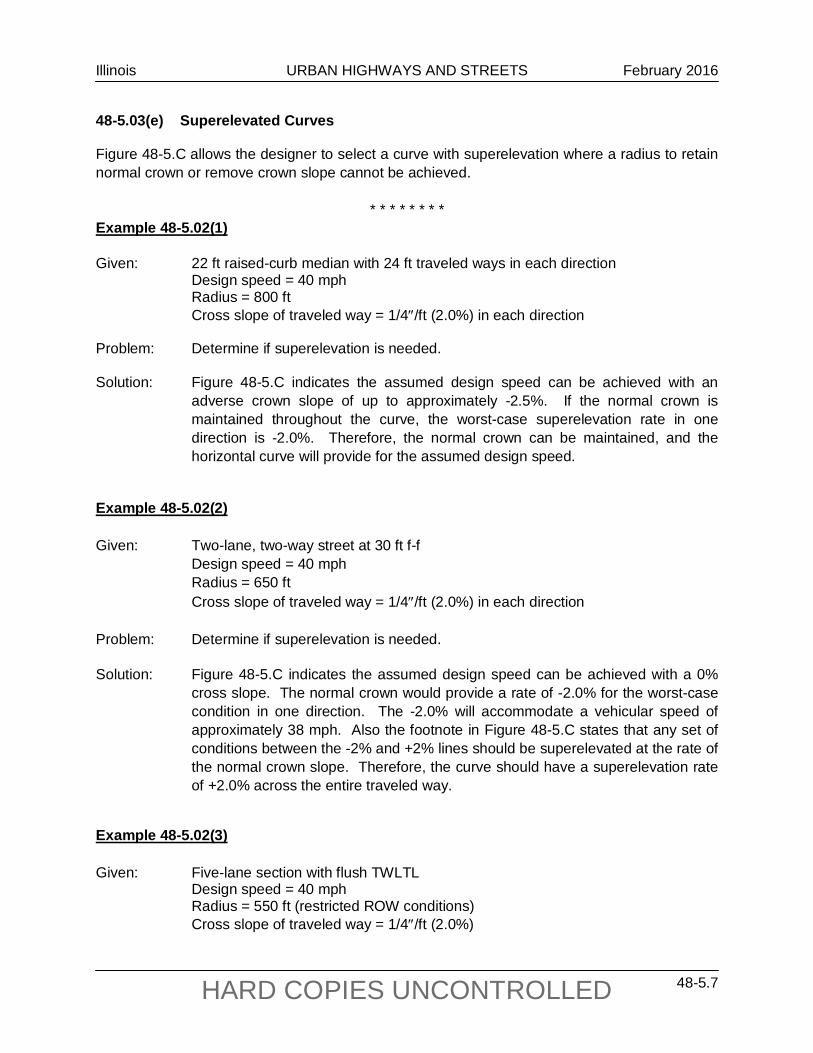
48-5.03(e) Superelevated Curves
Figure 48-5.C allows the designer to select a curve with superelevation where a radius to retain normal crown or remove crown slope cannot be achieved.
* * * * * * * *
Example 48-5.02(1) Given: 22 ft raised-curb median with 24 ft traveled ways in each direction Design speed = 40 mph Radius = 800 ft Cross slope of traveled way = 1/4″/ft (2.0%) in each direction Problem: Determine if superelevation is needed. Solution: Figure 48-5.C indicates the assumed design speed can be achieved with an
adverse crown slope of up to approximately -2.5%. If the normal crown is maintained throughout the curve, the worst-case superelevation rate in one direction is -2.0%. Therefore, the normal crown can be maintained, and the horizontal curve will provide for the assumed design speed.
Example 48-5.02(2) Given: Two-lane, two-way street at 30 ft f-f Design speed = 40 mph Radius = 650 ft Cross slope of traveled way = 1/4″/ft (2.0%) in each direction Problem: Determine if superelevation is needed. Solution: Figure 48-5.C indicates the assumed design speed can be achieved with a 0%
cross slope. The normal crown would provide a rate of -2.0% for the worst-case condition in one direction. The -2.0% will accommodate a vehicular speed of approximately 38 mph. Also the footnote in Figure 48-5.C states that any set of conditions between the -2% and +2% lines should be superelevated at the rate of the normal crown slope. Therefore, the curve should have a superelevation rate of +2.0% across the entire traveled way.
Example 48-5.02(3) Given: Five-lane section with flush TWLTL Design speed = 40 mph
Radius = 550 ft (restricted ROW conditions) Cross slope of traveled way = 1/4″/ft (2.0%)
Illinois URBAN HIGHWAYS AND STREETS February 2016
48-5.8 HARD COPIES UNCONTROLLED
Problem: Determine if superelevation is needed. Solution: Figure 48-5.C yields a rate of 4.0%, which is the maximum allowable rate for new
construction. Therefore, the entire traveled way should be transitioned and superelevated at this rate. Because this is a five-lane section, use Type M-2.12 Concrete Curb and Gutter on both median edges of the horizontal curve for improved drainage.
* * * * * * * *
48-5.03(f) Maximum Deflection Without Curve
It may be appropriate to omit a horizontal curve where very small deflection angles are present. As a guide, the designer may retain deflection angles of about 1° or less on low-speed urban streets. For these angles, the absence of a horizontal curve should not affect aesthetics.
48-5.04 Superelevation Development
48-5.04(a) Transition Length
The superelevation transition length is the distance required to transition the traveled way from a normal crown section to the full design superelevated section. The superelevation transition length is the sum of the tangent runout distance and superelevation runoff length. See Section 32-3. The following applies to low-speed urban streets:
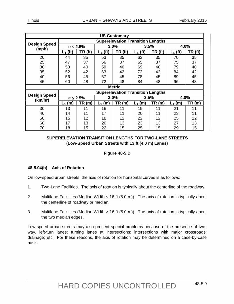
1. Calculation. Section 32-3 presents the methodology for calculating the superelevation runoff and tangent runout for open roadway conditions. This methodology also applies to superelevation transition lengths on low-speed urban streets. Figure 48-5.D presents superelevation runoff lengths (L1) and tangent runout lengths (TR) for a two-lane urban street, assuming the axis of rotation is about the roadway centerline; i.e., the width of rotation is one travel lane (13 ft (4.0 m)). See Section 32-3 for guidelines on determining modifications to the superelevation transition distance where the width of rotation is more than one travel lane. Include the plot of the pavement edges in the construction plans to ensure a smooth profile design. See Section 63-4.07(b).
2. Portion of Superelevation Runoff Prior to Curve. Typically, 67% of the superelevation runoff length will be placed on tangent and 33% on curve. Exceptions to this practice may be necessary to meet field conditions. Generally, the accepted range is 60%-80% on tangent and 40%-20% on curve.
Illinois URBAN HIGHWAYS AND STREETS February 2016
48-5.9 HARD COPIES UNCONTROLLED
US Customary
Design Speed (mph)
Superelevation Transition Lengths e ≤ 2.5% 3.0% 3.5% 4.0%
L1 (ft) TR (ft) L1 (ft) TR (ft) L1 (ft) TR (ft) L1 (ft) TR (ft) 20 25 30 35 40 45
44 47 50 52 56 60
35 37 40 42 45 48
53 56 59 63 67 72
35 37 40 42 45 48
62 65 69 73 78 84
35 37 40 42 45 48
70 75 79 84 89 96
35 37 40 42 45 48
Metric
Design Speed (km/hr)
Superelevation Transition Lengths e ≤ 2.5% 3.0% 3.5% 4.0%
L1 (m) TR (m) L1 (m) TR (m) L1 (m) TR (m) L1 (m) TR (m) 30 40 50 60 70
13 14 15 17 18
11 11 12 13 15
16 17 18 20 22
11 11 12 13 15
19 20 22 23 25
11 11 12 13 15
21 23 25 27 29
11 11 12 13 15
SUPERELEVATION TRANSITION LENGTHS FOR TWO-LANE STREETS (Low-Speed Urban Streets with 13 ft (4.0 m) Lanes)
Figure 48-5.D 48-5.04(b) Axis of Rotation
On low-speed urban streets, the axis of rotation for horizontal curves is as follows:
1. Two-Lane Facilities. The axis of rotation is typically about the centerline of the roadway.
2. Multilane Facilities (Median Width ≤ 16 ft (5.0 m)). The axis of rotation is typically about the centerline of roadway or median.
3. Multilane Facilities (Median Width > 16 ft (5.0 m)). The axis of rotation is typically about the two median edges.
Low-speed urban streets may also present special problems because of the presence of two-way, left-turn lanes; turning lanes at intersections; intersections with major crossroads; drainage; etc. For these reasons, the axis of rotation may be determined on a case-by-case basis.
Illinois URBAN HIGHWAYS AND STREETS February 2016
48-5.10 HARD COPIES UNCONTROLLED
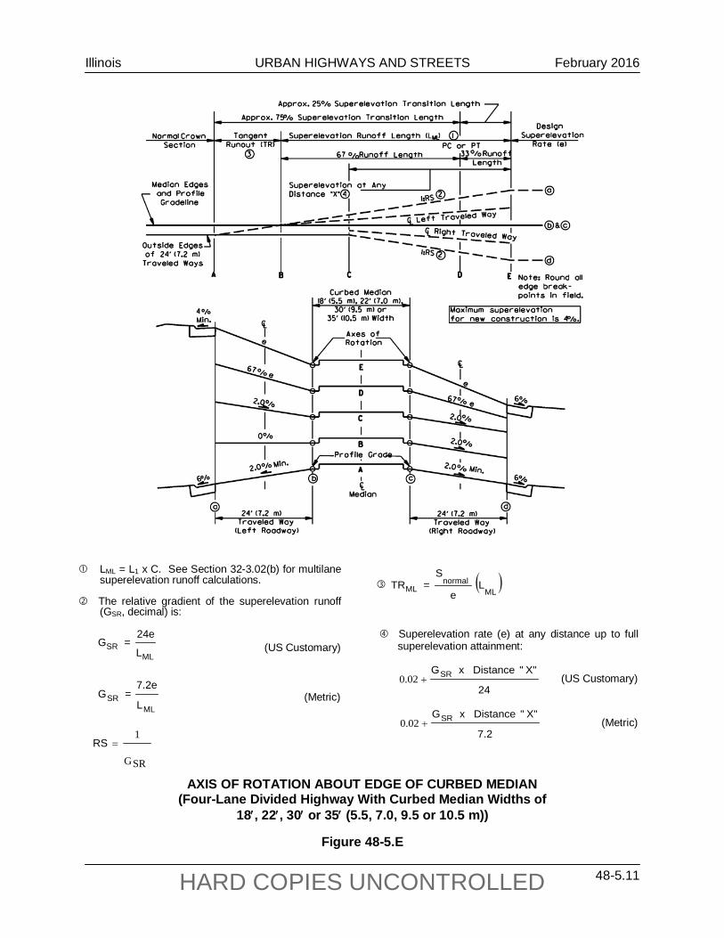
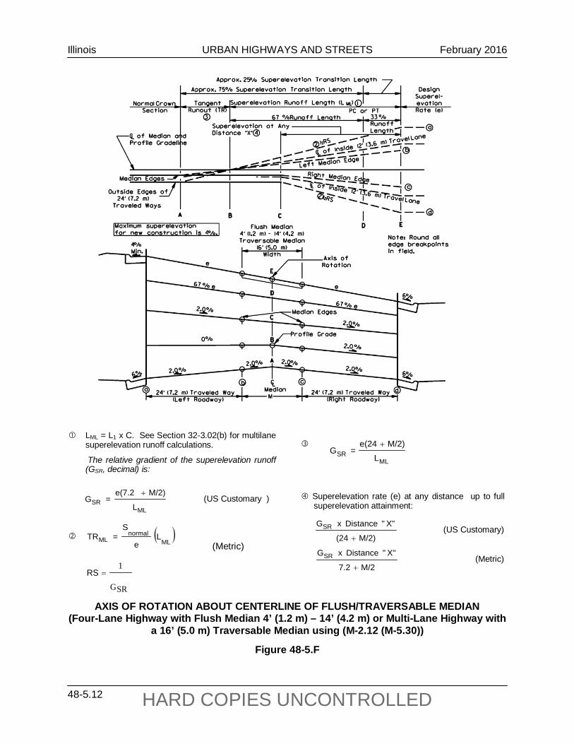
48-5.05 Typical Designs
See Figures 48-5.E and 48-5.F for typical multilane designs on low-speed urban streets that illustrate the superelevation transitions. See Figure 32-3.J for superelevation transitions on two-lane streets.
Illinois URBAN HIGHWAYS AND STREETS February 2016
48-5.11 HARD COPIES UNCONTROLLED
MLSR
L
24e=G
MLSR
L
7.2e=G
LML = L1 x C. See Section 32-3.02(b) for multilane superelevation runoff calculations.
The relative gradient of the superelevation runoff (GSR, decimal) is:
(US Customary) (Metric)
AXIS OF ROTATION ABOUT EDGE OF CURBED MEDIAN (Four-Lane Divided Highway With Curbed Median Widths of
18′, 22′, 30′ or 35′ (5.5, 7.0, 9.5 or 10.5 m))
Figure 48-5.E
GSR
1=RS
( )ML
normalML L
e
S=TR
Superelevation rate (e) at any distance up to full superelevation attainment:
24
X""DistancexGSR+02.0 (US Customary)
7.2
X""DistancexGSR+02.0 (Metric)
Illinois URBAN HIGHWAYS AND STREETS February 2016
48-5.12 HARD COPIES UNCONTROLLED
LML = L1 x C. See Section 32-3.02(b) for multilane superelevation runoff calculations.
The relative gradient of the superelevation runoff (GSR, decimal) is:
MLSR
L
M/2)e(7.2=G
+ (US Customary )
( )ML
normalML L
e
S=TR
(Metric)
GSR
1=RS
AXIS OF ROTATION ABOUT CENTERLINE OF FLUSH/TRAVERSABLE MEDIAN (Four-Lane Highway with Flush Median 4’ (1.2 m) – 14’ (4.2 m) or Multi-Lane Highway with
a 16’ (5.0 m) Traversable Median using (M-2.12 (M-5.30))
Figure 48-5.F
Superelevation rate (e) at any distance up to full superelevation attainment:
M/2)(24
X""DistancexGSR
+ (US Customary)
M/27.2
X""DistancexGSR
+ (Metric)
MLSR L
M/2)e(24=G
+
Illinois URBAN HIGHWAYS AND STREETS October 2015
48-6.1 HARD COPIES UNCONTROLLED
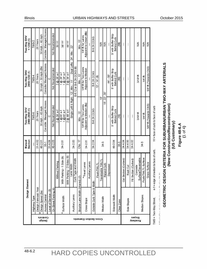
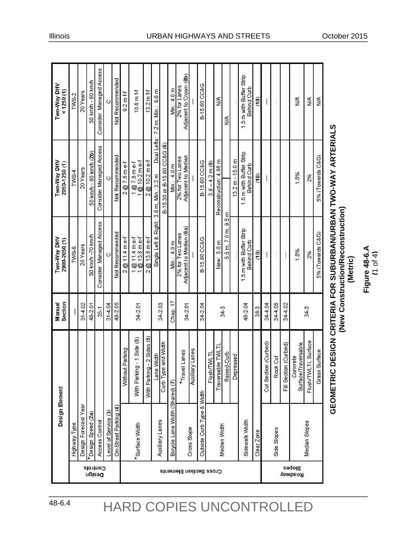
48-6 TABLES OF DESIGN CRITERIA
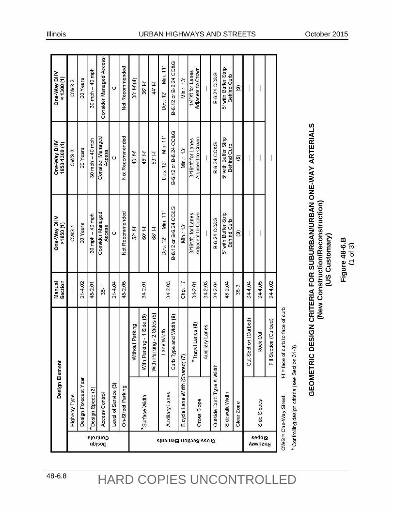
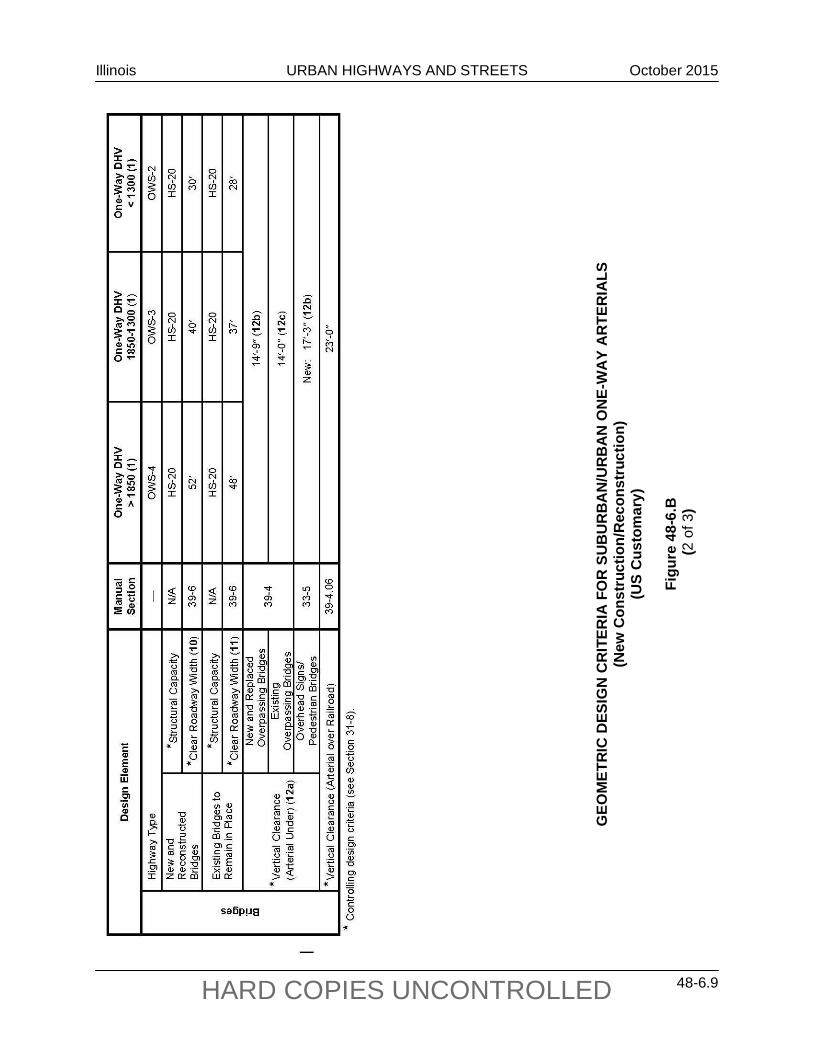
Figures 48-6.A, 48-6.B, and 48-6.C provide the criteria for urban streets with raised-curb medians, two-way left-turn lane medians, and one-way streets. Where it has been decided that the cross section design should be a depressed median with outside shoulders (i.e., open suburban area), use the criteria presented in Chapter 47 for rural four-lane arterials.
The designer should realize that some of the cross section elements included in the figures (e.g., TWLTL) are not automatically warranted in the project design. The values in the figures only apply after the decision has been made to include the element in the highway cross section.
Illinois URBAN HIGHWAYS AND STREETS October 2015
48-6.2 HARD COPIES UNCONTROLLED
GEO
MET
RIC
DES
IGN
CR
ITER
IA F
OR
SU
BU
RB
AN
/UR
BA
N T
WO
-WA
Y A
RTE
RIA
LS
(New
Con
stru
ctio
n/R
econ
stru
ctio
n)
(US
Cus
tom
ary)
Fi
gure
48-
6.A
(1
of 4
)
Illinois URBAN HIGHWAYS AND STREETS October 2015
48-6.3 HARD COPIES UNCONTROLLED
GEO
MET
RIC
DES
IGN
CR
ITER
IA F
OR
SU
BU
RB
AN
/UR
BA
N T
WO
-WA
Y A
RTE
RIA
LS
(New
Con
stru
ctio
n/R
econ
stru
ctio
n)
(US
Cus
tom
ary)
FI
GU
RE
48-6
.A
(2 o
f 4)
Illinois URBAN HIGHWAYS AND STREETS October 2015
48-6.4 HARD COPIES UNCONTROLLED
GEO
MET
RIC
DES
IGN
CR
ITER
IA F
OR
SU
BU
RB
AN
/UR
BA
N T
WO
-WA
Y A
RTE
RIA
LS
(New
Con
stru
ctio
n/R
econ
stru
ctio
n)
(Met
ric)
Figu
re 4
8-6.
A
(1 o
f 4)
Illinois URBAN HIGHWAYS AND STREETS October 2015
48-6.5 HARD COPIES UNCONTROLLED
G
EOM
ETR
IC D
ESIG
N C
RIT
ERIA
FOR
SU
BU
RB
AN
/UR
BA
N T
WO
-WA
Y A
RTE
RIA
LS
(New
Con
stru
ctio
n/R
econ
stru
ctio
n)
(Met
ric)
FIG
UR
E 48
-6.A
(2
of 4
)
Illinois URBAN HIGHWAYS AND STREETS October 2015
48-6.6 HARD COPIES UNCONTROLLED
GEO
MET
RIC
DES
IGN
CR
ITER
IA F
OR
SU
BU
RB
AN
/UR
BA
N T
WO
-WA
Y A
RTE
RIA
LS
(New
Con
stru
ctio
n/R
econ
stru
ctio
n)
Foot
note
s fo
r Fig
ure
48-6
.A
(3 o
f 4)
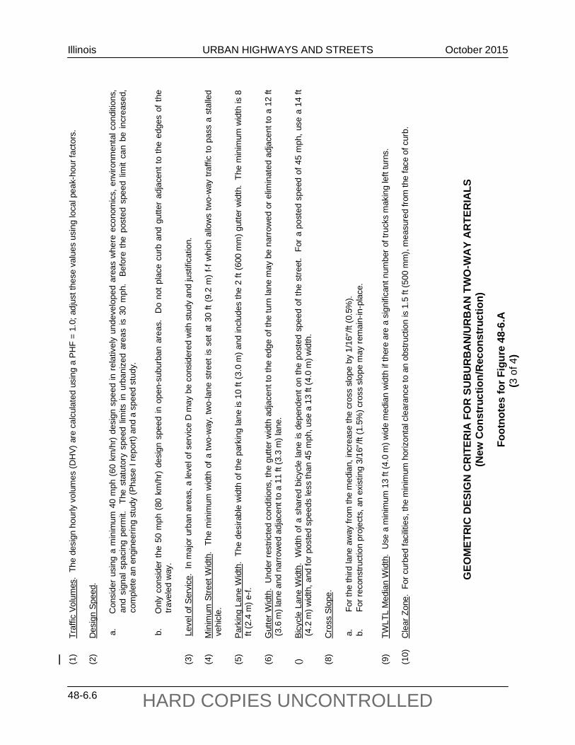
(1)
Traf
fic V
olum
es.
The
desi
gn h
ourly
vol
umes
(DH
V) a
re c
alcu
late
d us
ing
a PH
F =
1.0;
adj
ust t
hese
val
ues
usin
g lo
cal p
eak-
hour
fact
ors.
(2
) D
esig
n Sp
eed.
a.
Con
side
r us
ing
a m
inim
um 4
0 m
ph (
60 k
m/h
r) de
sign
spe
ed in
rel
ativ
ely
unde
velo
ped
area
s w
here
eco
nom
ics,
env
ironm
enta
l con
ditio
ns,
and
sign
al s
paci
ng p
erm
it.
The
stat
utor
y sp
eed
limits
in u
rban
ized
are
as is
30
mph
. B
efor
e th
e po
sted
spe
ed li
mit
can
be in
crea
sed,
co
mpl
ete
an e
ngin
eerin
g st
udy
(Pha
se I
repo
rt) a
nd a
spe
ed s
tudy
.
b.
Onl
y co
nsid
er th
e 50
mph
(80
km
/hr)
des
ign
spee
d in
ope
n-su
burb
an a
reas
. D
o no
t pla
ce c
urb
and
gutte
r ad
jace
nt to
the
edge
s of
the
trave
led
way
. (3
) L
evel
of S
ervi
ce.
In m
ajor
urb
an a
reas
, a le
vel o
f ser
vice
D m
ay b
e co
nsid
ered
with
stu
dy a
nd ju
stifi
catio
n.
(4)
Min
imum
Stre
et W
idth
. Th
e m
inim
um w
idth
of a
two-
way
, tw
o-la
ne s
treet
is s
et a
t 30
ft (9
.2 m
) f-f
whi
ch a
llow
s tw
o-w
ay tr
affic
to p
ass
a st
alle
d ve
hicl
e.
(5)
Park
ing
Lane
Wid
th.
The
desi
rabl
e w
idth
of t
he p
arki
ng la
ne is
10
ft (3
.0 m
) and
incl
udes
the
2 ft
(600
mm
) gut
ter w
idth
. Th
e m
inim
um w
idth
is 8
ft
(2.4
m) e
-f.
(6)
Gut
ter W
idth
. U
nder
rest
ricte
d co
nditi
ons,
the
gutte
r wid
th a
djac
ent t
o th
e ed
ge o
f the
turn
lane
may
be
narro
wed
or e
limin
ated
adj
acen
t to
a 12
ft
(3.6
m) l
ane
and
narro
wed
adj
acen
t to
a 11
ft (3
.3 m
) lan
e.
() Bi
cycl
e La
ne W
idth
. W
idth
of a
sha
red
bicy
cle
lane
is d
epen
dent
on
the
post
ed s
peed
of t
he s
treet
. Fo
r a
post
ed s
peed
of 4
5 m
ph, u
se a
14
ft (4
.2 m
) wid
th, a
nd fo
r pos
ted
spee
ds le
ss th
an 4
5 m
ph, u
se a
13
ft (4
.0 m
) wid
th.
(8)
Cro
ss S
lope
.
a.
Fo
r the
third
lane
aw
ay fr
om th
e m
edia
n, in
crea
se th
e cr
oss
slop
e by
1/1
6″/ft
(0.5
%).
b.
For r
econ
stru
ctio
n pr
ojec
ts, a
n ex
istin
g 3/
16″/
ft (1
.5%
) cro
ss s
lope
may
rem
ain-
in-p
lace
.
(9)
TWLT
L M
edia
n W
idth
. U
se a
min
imum
13
ft (4
.0 m
) wid
e m
edia
n w
idth
if th
ere
are
a si
gnifi
cant
num
ber o
f tru
cks
mak
ing
left
turn
s.
(10)
C
lear
Zon
e. F
or c
urbe
d fa
cilit
ies,
the
min
imum
hor
izon
tal c
lear
ance
to a
n ob
stru
ctio
n is
1.5
ft (5
00 m
m),
mea
sure
d fro
m th
e fa
ce o
f cur
b.
Illinois URBAN HIGHWAYS AND STREETS October 2015
48-6.7 HARD COPIES UNCONTROLLED
GEO
MET
RIC
DES
IGN
CR
ITER
IA F
OR
SU
BU
RB
AN
/UR
BA
N T
WO
-WA
Y A
RTE
RIA
LS
(New
Con
stru
ctio
n/R
econ
stru
ctio
n)
Foot
note
s fo
r Fig
ure
48-6
.A
(4 o
f 4)
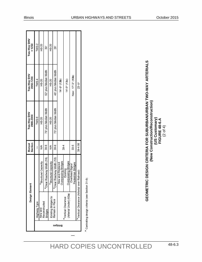
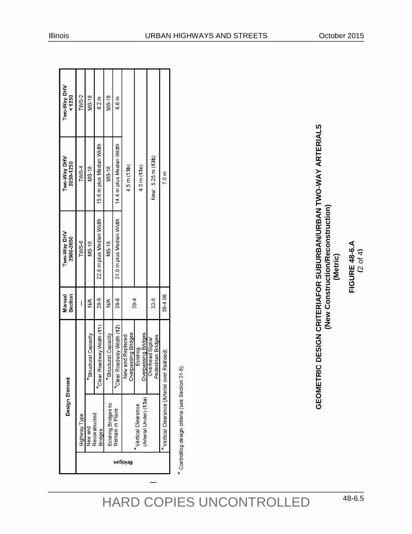
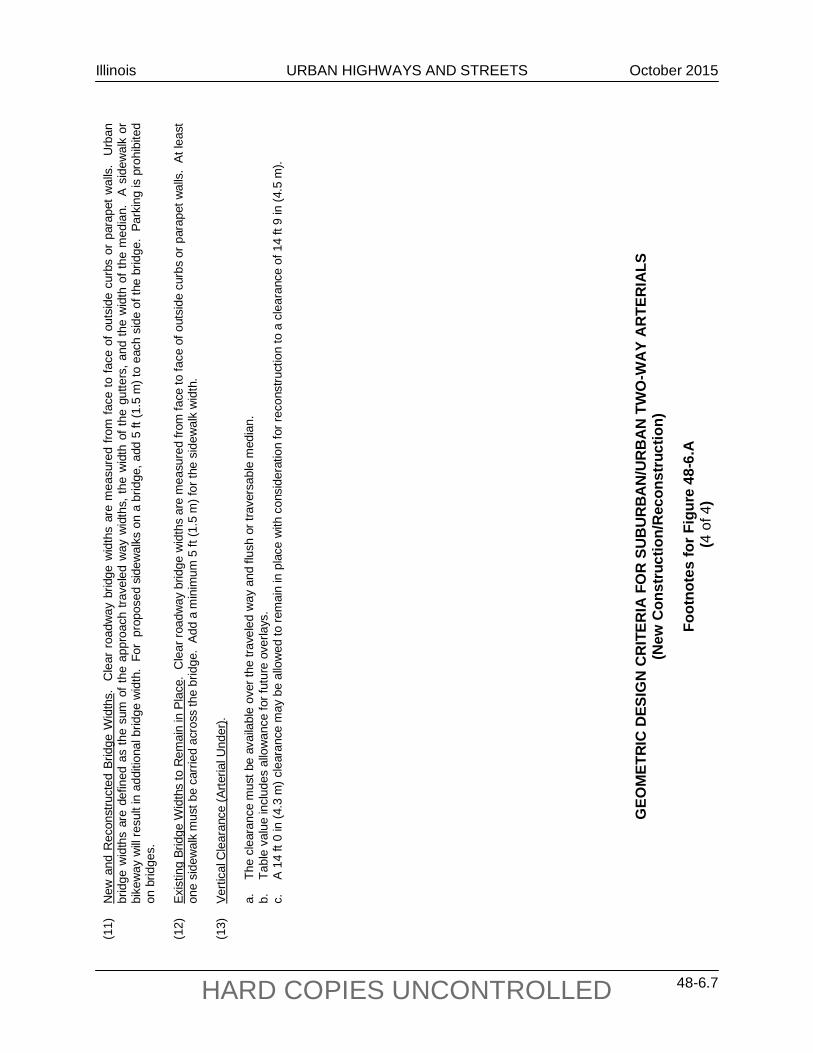
(11)
N
ew a
nd R
econ
stru
cted
Brid
ge W
idth
s.
Cle
ar r
oadw
ay b
ridge
wid
ths
are
mea
sure
d fro
m fa
ce to
face
of o
utsi
de c
urbs
or
para
pet w
alls
. U
rban
br
idge
wid
ths
are
defin
ed a
s th
e su
m o
f the
app
roac
h tra
vele
d w
ay w
idth
s, th
e w
idth
of t
he g
utte
rs, a
nd th
e w
idth
of t
he m
edia
n.
A si
dew
alk
or
bike
way
will
resu
lt in
add
ition
al b
ridge
wid
th.
For
prop
osed
sid
ewal
ks o
n a
brid
ge, a
dd 5
ft (1
.5 m
) to
each
sid
e of
the
brid
ge.
Park
ing
is p
rohi
bite
d on
brid
ges.
(1
2)
Exis
ting
Brid
ge W
idth
s to
Rem
ain
in P
lace
. C
lear
road
way
brid
ge w
idth
s ar
e m
easu
red
from
face
to fa
ce o
f out
side
cur
bs o
r par
apet
wal
ls.
At le
ast
one
side
wal
k m
ust b
e ca
rrie
d ac
ross
the
brid
ge.
Add
a m
inim
um 5
ft (1
.5 m
) for
the
side
wal
k w
idth
. (1
3)
Verti
cal C
lear
ance
(Arte
rial U
nder
).
a.
The
clea
ranc
e m
ust b
e av
aila
ble
over
the
trave
led
way
and
flus
h or
trav
ersa
ble
med
ian.
b.
Ta
ble
valu
e in
clud
es a
llow
ance
for f
utur
e ov
erla
ys.
c.
A 14
ft 0
in (4
.3 m
) cle
aran
ce m
ay b
e al
low
ed to
rem
ain
in p
lace
with
con
side
ratio
n fo
r rec
onst
ruct
ion
to a
cle
aran
ce o
f 14
ft 9
in (4
.5 m
).
Illinois URBAN HIGHWAYS AND STREETS October 2015
48-6.8 HARD COPIES UNCONTROLLED
GEO
MET
RIC
DES
IGN
CR
ITER
IA F
OR
SU
BU
RB
AN
/UR
BA
N O
NE-
WA
Y A
RTE
RIA
LS
(New
Con
stru
ctio
n/R
econ
stru
ctio
n)
(US
Cus
tom
ary)
Figu
re 4
8-6.
B
(1 o
f 3)
Illinois URBAN HIGHWAYS AND STREETS October 2015
48-6.9 HARD COPIES UNCONTROLLED
GEO
MET
RIC
DES
IGN
CR
ITER
IA F
OR
SU
BU
RB
AN
/UR
BA
N O
NE-
WA
Y A
RTE
RIA
LS
(New
Con
stru
ctio
n/R
econ
stru
ctio
n)
(US
Cus
tom
ary)
(C
ontin
ued)
Figu
re 4
8-6.
B
GEO
MET
RIC
DES
IGN
CR
ITER
IA F
OR
SU
BU
RB
AN
/UR
BA
N O
NE-
WA
Y A
RTE
RIA
LS
(New
Con
stru
ctio
n/R
econ
stru
ctio
n)
(US
Cus
tom
ary)
Figu
re 4
8-6.
B
(2 o
f 3)
Illinois URBAN HIGHWAYS AND STREETS October 2015
48-6.10 HARD COPIES UNCONTROLLED
GEO
MET
RIC
DES
IGN
CR
ITER
IA F
OR
SU
BU
RB
AN
/UR
BA
N O
NE-
WA
Y A
RTE
RIA
LS
(New
Con
stru
ctio
n/R
econ
stru
ctio
n)
(Met
ric)
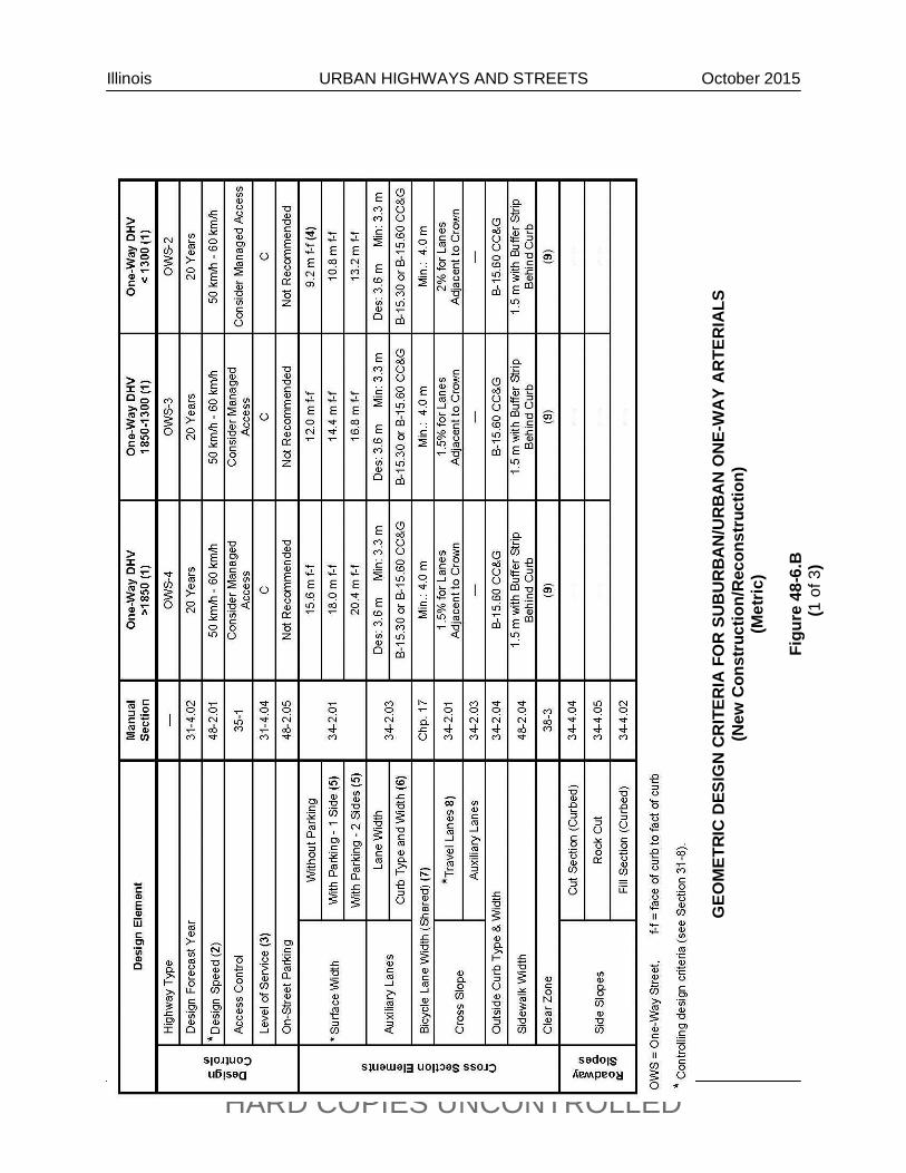
Fi
gure
48-
6.B
(1
of 3
)
Illinois URBAN HIGHWAYS AND STREETS October 2015
48-6.11 HARD COPIES UNCONTROLLED
GEO
MET
RIC
DES
IGN
CR
ITER
IA F
OR
SU
BU
RB
AN
/UR
BA
N O
NE-
WA
Y A
RTE
RIA
LS
(New
Con
stru
ctio
n/R
econ
stru
ctio
n)
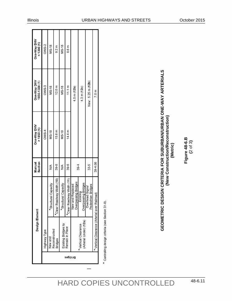
(Met
ric)
Figu
re 4
8-6.
B
(2 o
f 3)
Illinois URBAN HIGHWAYS AND STREETS October 2015
48-6.12 HARD COPIES UNCONTROLLED
GEO
MET
RIC
DES
IGN
CR
ITER
IA F
OR
SU
BU
RB
AN
/UR
BA
N O
NE-
WA
Y A
RTE
RIA
LS
(New
Con
stru
ctio
n/R
econ
stru
ctio
n)
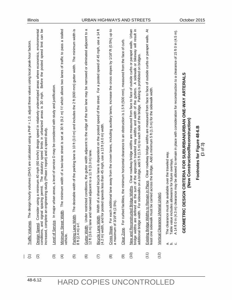
Foot
note
s fo
r Fig
ure
48-6
.B
(3 o
f 3)
(1)
Traf
fic V
olum
es.
The
desi
gn h
ourly
vol
umes
(DH
V) a
re c
alcu
late
d us
ing
a PH
F =
1.0;
adj
ust t
hese
val
ues
usin
g lo
cal p
eak-
hour
fact
ors.
(2
) D
esig
n Sp
eed.
Con
side
r usi
ng a
min
imum
40
mph
(60
km/h
r) d
esig
n sp
eed
in re
lativ
ely
unde
velo
ped
area
s w
here
eco
nom
ics,
env
ironm
enta
l co
nditi
ons,
and
sig
nal
spac
ing
perm
it.
The
stat
utor
y sp
eed
limits
in
urba
nize
d ar
eas
is 3
0 m
ph.
Bef
ore
the
post
ed s
peed
lim
it ca
n be
in
crea
sed,
com
plet
e an
eng
inee
ring
stud
y (P
hase
I re
port)
and
a s
peed
stu
dy.
(3)
Leve
l of S
ervi
ce.
In m
ajor
urb
an a
reas
, a le
vel o
f ser
vice
D m
ay b
e co
nsid
ered
with
stu
dy a
nd ju
stifi
catio
n.
(4)
Min
imum
Stre
et W
idth
. Th
e m
inim
um w
idth
of a
two-
lane
stre
et is
set
at 3
0 ft
(9.2
m)
f-f w
hich
allo
ws
two
lane
s of
traf
fic to
pas
s a
stal
led
vehi
cle.
(5
) Pa
rkin
g La
ne W
idth
. Th
e de
sira
ble
wid
th o
f the
par
king
lane
is 1
0 ft
(3.0
m) a
nd in
clud
es th
e 2
ft (6
00 m
m) g
utte
r wid
th.
The
min
imum
wid
th is
8
ft (2
.4 m
) e-f.
(6
) G
utte
r Wid
th.
Und
er re
stric
ted
cond
ition
s, th
e gu
tter w
idth
adj
acen
t to
the
edge
of t
he tu
rn la
ne m
ay b
e na
rrow
ed o
r elim
inat
ed a
djac
ent t
o a
12 ft
(3.6
m) l
ane
and
narro
wed
adj
acen
t to
a 11
ft (3
.3 m
) lan
e.
(7)
Bicy
cle
Lane
Wid
th.
Wid
th o
f a s
hare
d bi
cycl
e la
ne is
dep
ende
nt o
n th
e po
sted
spe
ed o
f the
stre
et.
For a
pos
ted
spee
d of
45
mph
, use
a 1
4 ft
(4.2
m) w
idth
, and
for p
oste
d sp
eeds
less
than
45
mph
, use
a 1
3 ft
(4.0
m) w
idth
. (8
) C
ross
Slo
pe.
For e
ach
addi
tiona
l lan
e aw
ay fr
om th
e cr
own
lane
s, in
clud
ing
auxi
liary
lane
s, in
crea
se th
e cr
oss
slop
es b
y 1/
16″/
ft (0
.5%
) up
to
a m
axim
um o
f 3/1
6″/ft
(2.5
%).
(9)
Cle
ar Z
one.
For
cur
bed
faci
litie
s, th
e m
inim
um h
oriz
onta
l cle
aran
ce to
an
obst
ruct
ion
is 1
.5 ft
(500
mm
), m
easu
red
from
the
face
of c
urb.
(1
0)
New
and
Rec
onst
ruct
ed B
ridge
Wid
ths.
Cle
ar ro
adw
ay b
ridge
wid
ths
are
mea
sure
d fro
m fa
ce to
face
of o
utsi
de c
urbs
or p
arap
et w
alls
. U
rban
br
idge
wid
ths
are
defin
ed a
s th
e su
m o
f th
e ap
proa
ch t
rave
led
way
wid
ths
and
wid
th o
f th
e gu
tters
. A
sid
ewal
k or
bik
eway
will
resu
lt in
ad
ditio
nal b
ridge
wid
th.
For s
idew
alks
on
a br
idge
, add
5 ft
(1.5
m) t
o ea
ch s
ide
of th
e br
idge
. Pa
rkin
g is
pro
hibi
ted
on b
ridge
s.
(11)
Ex
istin
g Br
idge
Wid
ths
to R
emai
n in
Pla
ce.
Cle
ar ro
adw
ay b
ridge
wid
ths
are
mea
sure
d fro
m fa
ce to
face
of o
utsi
de c
urbs
or p
arap
et w
alls
. At
le
ast o
ne s
idew
alk
mus
t be
carri
ed a
cros
s th
e br
idge
. Ad
d a
min
imum
5 ft
(1.5
m) f
or th
e si
dew
alk
wid
th.
(12)
Ve
rtica
l Cle
aran
ce (A
rteria
l Und
er).
a.
Th
e cl
eara
nce
mus
t be
avai
labl
e ov
er th
e tra
vele
d w
ay.
b.
Tabl
e va
lue
incl
udes
allo
wan
ce fo
r fut
ure
over
lays
.
c.
A 14
ft 0
in (4
.3 m
) cle
aran
ce m
ay b
e al
low
ed to
rem
ain
in p
lace
with
con
side
ratio
n fo
r rec
onst
ruct
ion
to a
cle
aran
ce o
f 15
ft 0
in (4
.5 m
).

Illinois URBAN HIGHWAYS AND STREETS October 2015
48-6.13 HARD COPIES UNCONTROLLED
ALI
GN
MEN
T C
RIT
ERIA
FO
R S
UB
UR
BA
N/U
RB
AN
AR
TER
IALS
(N
ew C
onst
ruct
ion/
Rec
onst
ruct
ion)
(U
S C
usto
mar
y)
Figu
re 4
8-6.
C
Illinois URBAN HIGHWAYS AND STREETS October 2015
48-6.14 HARD COPIES UNCONTROLLED
ALI
GN
MEN
T C
RIT
ERIA
FO
R S
UB
UR
BA
N/U
RB
AN
AR
TER
IALS
(N
ew C
onst
ruct
ion/
Rec
onst
ruct
ion)
(M
etric
)
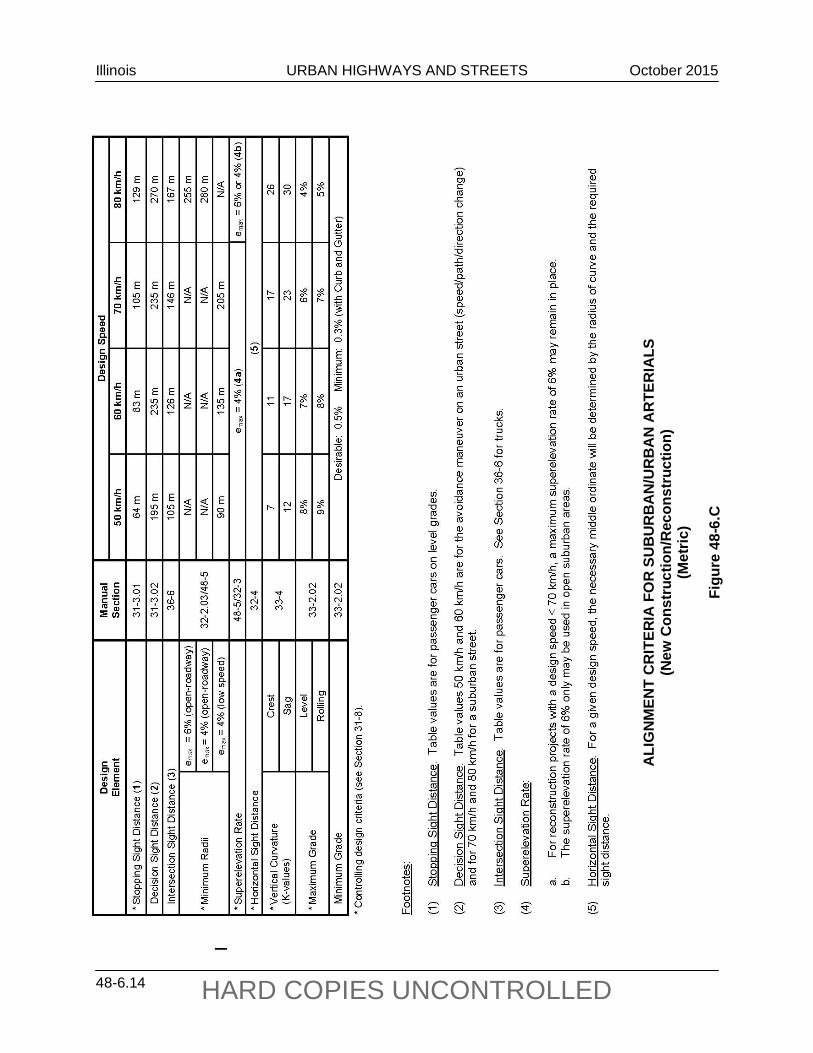
Figu
re 4
8-6.
C
Illinois URBAN HIGHWAYS AND STREETS September 2012
48-7.1 HARD COPIES UNCONTROLLED
48-7 REFERENCES
1. A Policy on Geometric Design of Highways and Streets, AASHTO, 2011.
2. Highway Capacity Manual 2010, Transportation Research Board, 2010.
3. Parking Principles, Special Report No. 125, Highway Research Board, 1971.
4. “Two-Way Left-Turn Lanes: State-of-the-Art Overview and Implementation Guide,” Transportation Research Record 681, TRB, 1978.
5. Effective Utilization of Street Width on Urban Arterials, NCHRP Report 330, 1990.
6. “Accident Comparison of Raised Median and Two-Way Left-Turn Lane Median Treatments,” Transportation Research Board 1239, TRB, 1989.
7. “Are Raised Medians Safer Than Two-Way Left-Turn Lanes?” ITE Journal, December 1994.
8. Multilane Design Alternatives for Improving Suburban Highways, NCHRP Report 282, 1986.
9. Median Intersection Design, NCHRP 375, 1995.
10. Capacity and Operational Effects of Midblock Left-Turn Lanes, NCHRP Report 395, September 1997.
11. Relationship of Operating Speed to Roadway Geometric Design Speed, FHWA RD-96-024, FHWA, December 1996.
12. Highway Standards, current edition.

Illinois URBAN HIGHWAYS AND STREETS September 2012
48-7.2 HARD COPIES UNCONTROLLED