upfc performance analysis in transmission line under ...ijplsjournal.com/issues...
TRANSCRIPT
Research Article Alam & Khan, 9(Spec. Issue), 2018:200-211]
ISSN: 0976-7126
© Sakun Publishing House (SPH) 200
Int. J. of P. & Life Sci. (Special Issue Engg. Tech.)
UPFC performance analysis in transmission line under unsymmetrical
faults condition 1Sharique Alam, 2Shadab Khan
1ME Scholar
Department of Electrical Engineering
Radharaman Engineering College, Bhopal, MP (India), 2Asst. Prof.
Department of Electrical Engineering
Radharaman Engineering College, Bhopal, MP (India)
Abstract
This paper deals with unified power flow controller (UPFC) for the transmission line under the pre fault and post
fault condition using the Simulink model of UPFC. Unified power flow controller is the type of flexible ac
transmission system (facts) having very important role in aiding for the stability of transmission line with an
interconnected system. Here in this paper the study of load bus under different unsymmetrical fault condition will be
studied along with effect in flow of power. The effect of connecting UPFC on the voltage profile along with flow of
power. Here a versatile model is used for simulation of UPFC with inherent order to improve transient stability and
damp oscillation. The entire system is designed and analysed using MATLAB/SIMULINK.
Key words: FACTS, UPFC, Series and Shunt compensators.
Introduction:-
Power system is nothing but the interconnection of generating units to the load consuming units through high
voltage capacity transmission line which is generally under control. It can be divided into 3 subsystems: generating
subsystem, transmission subsystem and distributing subsystem. In the late 1980s the Electric Power Research
Institute (EPRI) has introduced a new technology program known as Flexible AC Transmission System (FATCS).
The main idea behind this program is to increase controllability and optimize the utilization of the existing power
system capacities by replacing mechanical controllers by reliable and high-speed power electronic devices. In
present scenario, most of the power system in large developing countries with large inter connected network share
the generation reserve to increase the reliability of power system [1] this increases complexity and hence instability
of system.
The unified power flow control originally proposed by Gyugi in 1991. The unified power flow controller was
proposed for real time dynamic and controlling of power transmission system, along with providing flexibility of
solving many problems faced by power industry delivery authority within the bounds of traditional power
transmission concepts. Unified power flow controller along with aiding for an improved stability of system reduces
losses by damping of the oscillation due to harmonics. It does so by controlling all the parameters involve in the
control of power transfer like impedance, phase angle along with voltage while controlling the reactive power flow
into the circuit. Thus with variation in ‘x’ active power and reactive power can be varied. [4]Two important
Research Article Alam & Khan, 9(Spec. Issue), 2018:200-211]
ISSN: 0976-7126
© Sakun Publishing House (SPH) 201
parameters are taken in to consideration ability of system to maximise the load upto stability margin and reduce
active power losses. This experiment suggests the increase in the sustainability of power grid. The MATLAB results
is the proof of the capability of UPFC on effectiveness of controller and power flow while operating on different
modes.
A UPFC offers advantages for dynamic as well as static operation of power system. A transient stability and power
flowmodel of it, and a slightly different control strategy explains a efficient and simple control. Proposed model
represents the behavior of the controller in quasi-steady state operating conditions and it is adequate for transient,
steady state stability and analysis of power systems. The UPFC can enhance the performance of system under
abnormal conditions. There is a concern of optimal location of it to be selected. Because of the sizable length of
transmission lines the risk of angular instability is unescapable. The fast increase of demand load results in huge
amount of power transmitted through these lines. The angular stability can be studied in detail, to ensure a secure
and safe operation and in order to find the solutions, to improve the stability of the system. Strategies are developed
to attain optimum improvement in transient stability along with damping the oscillation of rotor using UPFC which
finally maximize and minimize the power flow in the line. In abstract it provides with the solution to constrained
optimization problem at each step of determining the voltage and current injected by it.Makobe and jenkin
experimentally proved that a UPFC can control the three control parameters either individually or in appropriate
combination of series-connected output while maintaining reactive power support at its shunt connected input device
[2] The model for Current injection is used to follow its effect on load flow.UPFC cannot control real power in
steady state except during losses, the STATCOM (Static synchronous Compensator) maintains constant bus voltage
thereby providing energy for DC link of SSSC and also maintain voltage of capacitor at the DC link.
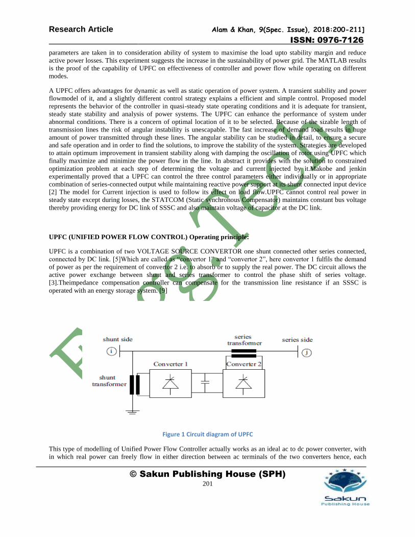
UPFC (UNIFIED POWER FLOW CONTROL) Operating principle:
UPFC is a combination of two VOLTAGE SOURCE CONVERTOR one shunt connected other series connected,
connected by DC link. [5]Which are called as “convertor 1” and “convertor 2”, here convertor 1 fulfils the demand
of power as per the requirement of convertor 2 i.e. to absorb or to supply the real power. The DC circuit allows the
active power exchange between shunt and series transformer to control the phase shift of series voltage.
[3].Theimpedance compensation controller can compensate for the transmission line resistance if an SSSC is
operated with an energy storage system. [9]
Figure 1 Circuit diagram of UPFC
This type of modelling of Unified Power Flow Controller actually works as an ideal ac to dc power converter, with
in which real power can freely flow in either direction between ac terminals of the two converters hence, each
Research Article Alam & Khan, 9(Spec. Issue), 2018:200-211]
ISSN: 0976-7126
© Sakun Publishing House (SPH) 202
converter can independently be generating or absorbing reactive power at its own AC output terminal.UPFC improves the voltage profile of the system and thus increase the load ability margin of the power system.[6].the UPFC can be commanded to force an appropriately varying power level that will effectively damp the power oscillation in the line.[7]
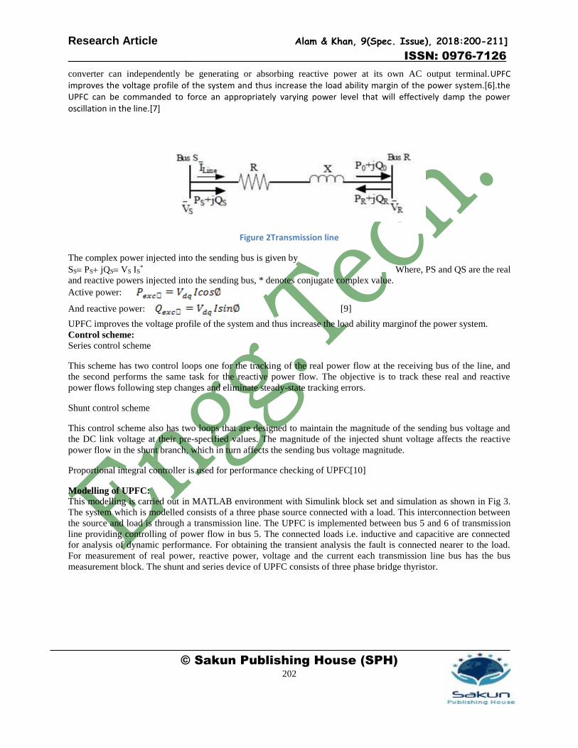
Figure 2Transmission line
The complex power injected into the sending bus is given by
SSPSjQSVS IS* Where, PS and QS are the real
and reactive powers injected into the sending bus, * denotes conjugate complex value.
Active power:
And reactive power: [9]
UPFC improves the voltage profile of the system and thus increase the load ability marginof the power system.
Control scheme:
Series control scheme
This scheme has two control loops one for the tracking of the real power flow at the receiving bus of the line, and
the second performs the same task for the reactive power flow. The objective is to track these real and reactive
power flows following step changes and eliminate steady-state tracking errors.
Shunt control scheme
This control scheme also has two loops that are designed to maintain the magnitude of the sending bus voltage and
the DC link voltage at their pre-specified values. The magnitude of the injected shunt voltage affects the reactive
power flow in the shunt branch, which in turn affects the sending bus voltage magnitude.
Proportional integral controller is used for performance checking of UPFC[10]
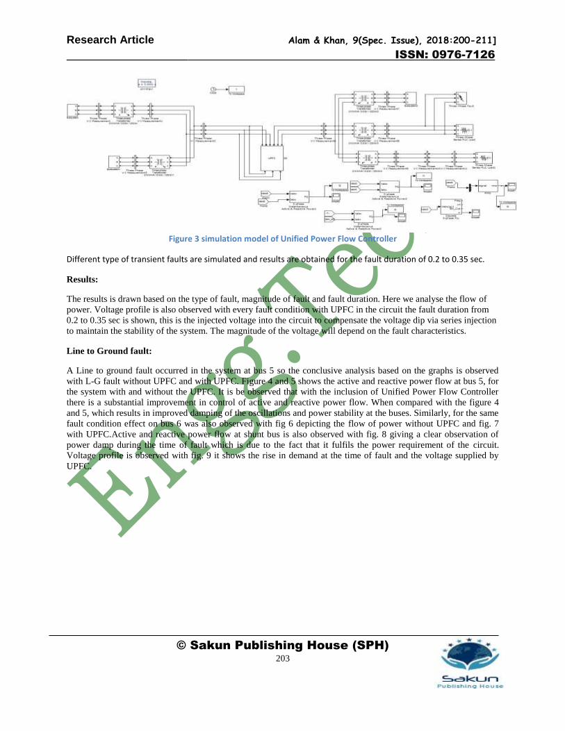
Modelling of UPFC:
This modelling is carried out in MATLAB environment with Simulink block set and simulation as shown in Fig 3.
The system which is modelled consists of a three phase source connected with a load. This interconnection between
the source and load is through a transmission line. The UPFC is implemented between bus 5 and 6 of transmission
line providing controlling of power flow in bus 5. The connected loads i.e. inductive and capacitive are connected
for analysis of dynamic performance. For obtaining the transient analysis the fault is connected nearer to the load.
For measurement of real power, reactive power, voltage and the current each transmission line bus has the bus
measurement block. The shunt and series device of UPFC consists of three phase bridge thyristor.
Research Article Alam & Khan, 9(Spec. Issue), 2018:200-211]
ISSN: 0976-7126
© Sakun Publishing House (SPH) 203
Figure 3 simulation model of Unified Power Flow Controller
Different type of transient faults are simulated and results are obtained for the fault duration of 0.2 to 0.35 sec.
Results:
The results is drawn based on the type of fault, magnitude of fault and fault duration. Here we analyse the flow of
power. Voltage profile is also observed with every fault condition with UPFC in the circuit the fault duration from
0.2 to 0.35 sec is shown, this is the injected voltage into the circuit to compensate the voltage dip via series injection
to maintain the stability of the system. The magnitude of the voltage will depend on the fault characteristics.
Line to Ground fault:
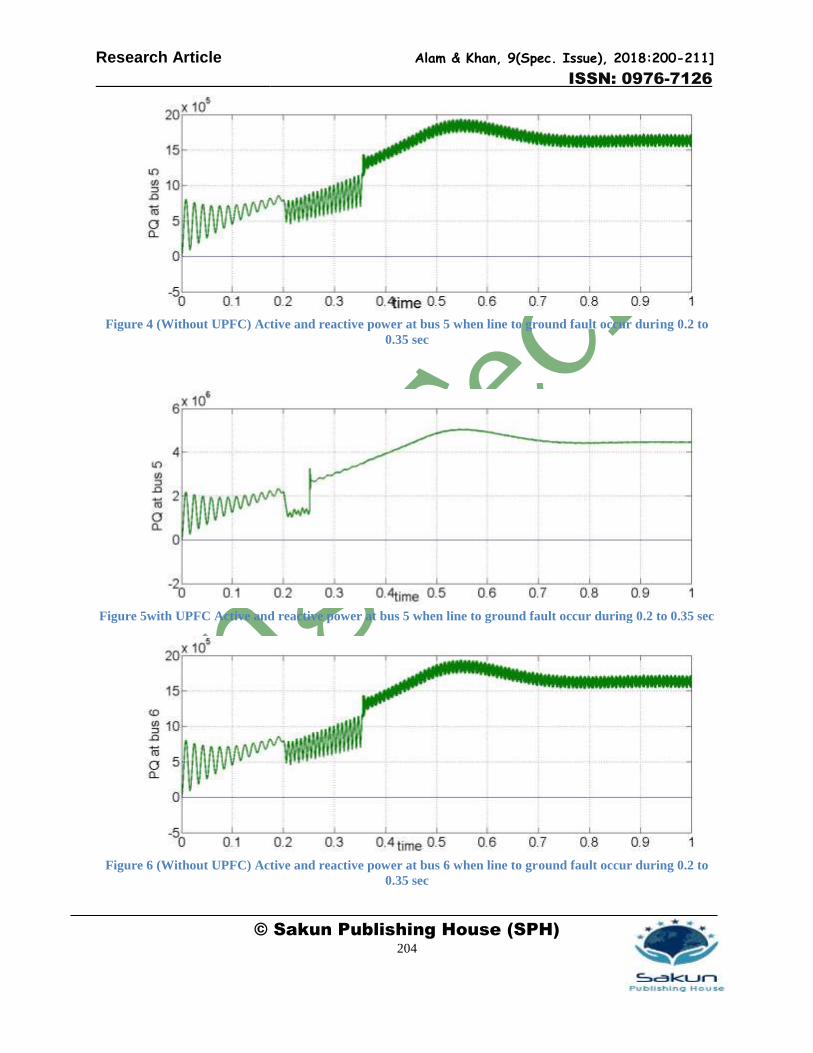
A Line to ground fault occurred in the system at bus 5 so the conclusive analysis based on the graphs is observed
with L-G fault without UPFC and with UPFC. Figure 4 and 5 shows the active and reactive power flow at bus 5, for
the system with and without the UPFC. It is be observed that with the inclusion of Unified Power Flow Controller
there is a substantial improvement in control of active and reactive power flow. When compared with the figure 4
and 5, which results in improved damping of the oscillations and power stability at the buses. Similarly, for the same
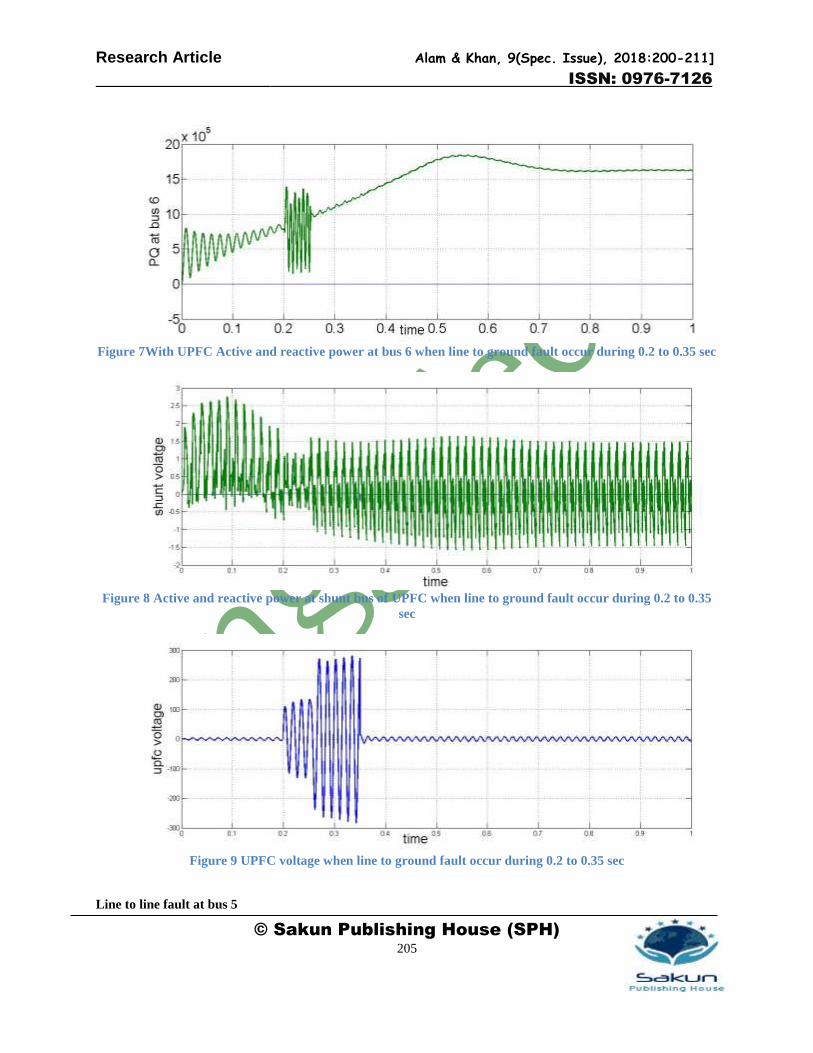
fault condition effect on bus 6 was also observed with fig 6 depicting the flow of power without UPFC and fig. 7
with UPFC.Active and reactive power flow at shunt bus is also observed with fig. 8 giving a clear observation of
power damp during the time of fault which is due to the fact that it fulfils the power requirement of the circuit.
Voltage profile is observed with fig. 9 it shows the rise in demand at the time of fault and the voltage supplied by
UPFC.
Research Article Alam & Khan, 9(Spec. Issue), 2018:200-211]
ISSN: 0976-7126
© Sakun Publishing House (SPH) 204
Figure 4 (Without UPFC) Active and reactive power at bus 5 when line to ground fault occur during 0.2 to
0.35 sec
Figure 5with UPFC Active and reactive power at bus 5 when line to ground fault occur during 0.2 to 0.35 sec
Figure 6 (Without UPFC) Active and reactive power at bus 6 when line to ground fault occur during 0.2 to
0.35 sec
Research Article Alam & Khan, 9(Spec. Issue), 2018:200-211]
ISSN: 0976-7126
© Sakun Publishing House (SPH) 205
Figure 7With UPFC Active and reactive power at bus 6 when line to ground fault occur during 0.2 to 0.35 sec
Figure 8 Active and reactive power at shunt bus of UPFC when line to ground fault occur during 0.2 to 0.35
sec
Figure 9 UPFC voltage when line to ground fault occur during 0.2 to 0.35 sec
Line to line fault at bus 5
Research Article Alam & Khan, 9(Spec. Issue), 2018:200-211]
ISSN: 0976-7126
© Sakun Publishing House (SPH) 206
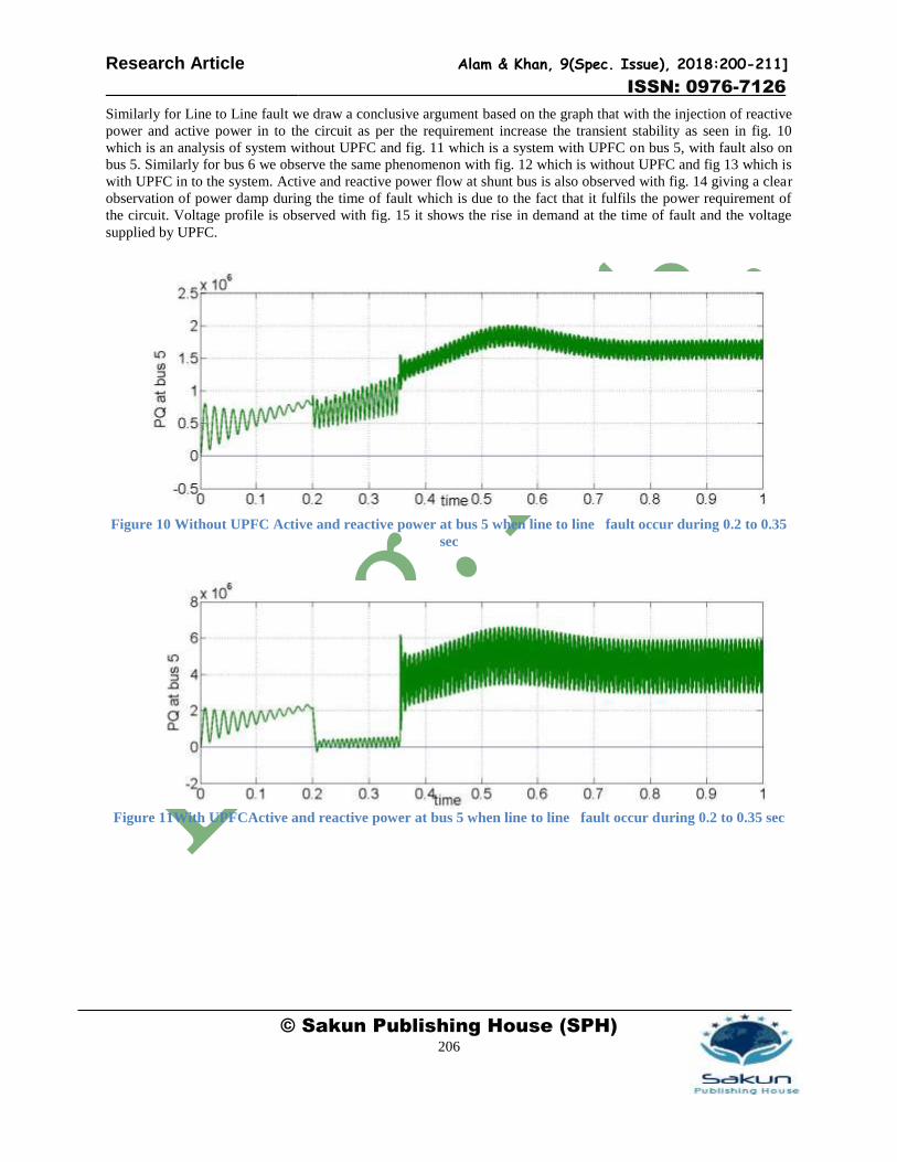
Similarly for Line to Line fault we draw a conclusive argument based on the graph that with the injection of reactive
power and active power in to the circuit as per the requirement increase the transient stability as seen in fig. 10
which is an analysis of system without UPFC and fig. 11 which is a system with UPFC on bus 5, with fault also on
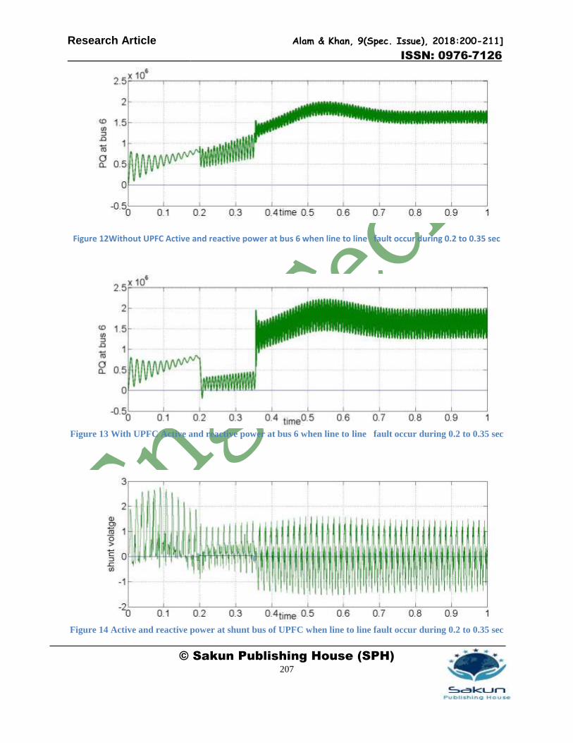
bus 5. Similarly for bus 6 we observe the same phenomenon with fig. 12 which is without UPFC and fig 13 which is
with UPFC in to the system. Active and reactive power flow at shunt bus is also observed with fig. 14 giving a clear
observation of power damp during the time of fault which is due to the fact that it fulfils the power requirement of
the circuit. Voltage profile is observed with fig. 15 it shows the rise in demand at the time of fault and the voltage
supplied by UPFC.
Figure 10 Without UPFC Active and reactive power at bus 5 when line to line fault occur during 0.2 to 0.35
sec
Figure 11With UPFCActive and reactive power at bus 5 when line to line fault occur during 0.2 to 0.35 sec
Research Article Alam & Khan, 9(Spec. Issue), 2018:200-211]
ISSN: 0976-7126
© Sakun Publishing House (SPH) 207
Figure 12Without UPFC Active and reactive power at bus 6 when line to line fault occur during 0.2 to 0.35 sec
Figure 13 With UPFC Active and reactive power at bus 6 when line to line fault occur during 0.2 to 0.35 sec
Figure 14 Active and reactive power at shunt bus of UPFC when line to line fault occur during 0.2 to 0.35 sec
Research Article Alam & Khan, 9(Spec. Issue), 2018:200-211]
ISSN: 0976-7126
© Sakun Publishing House (SPH) 208
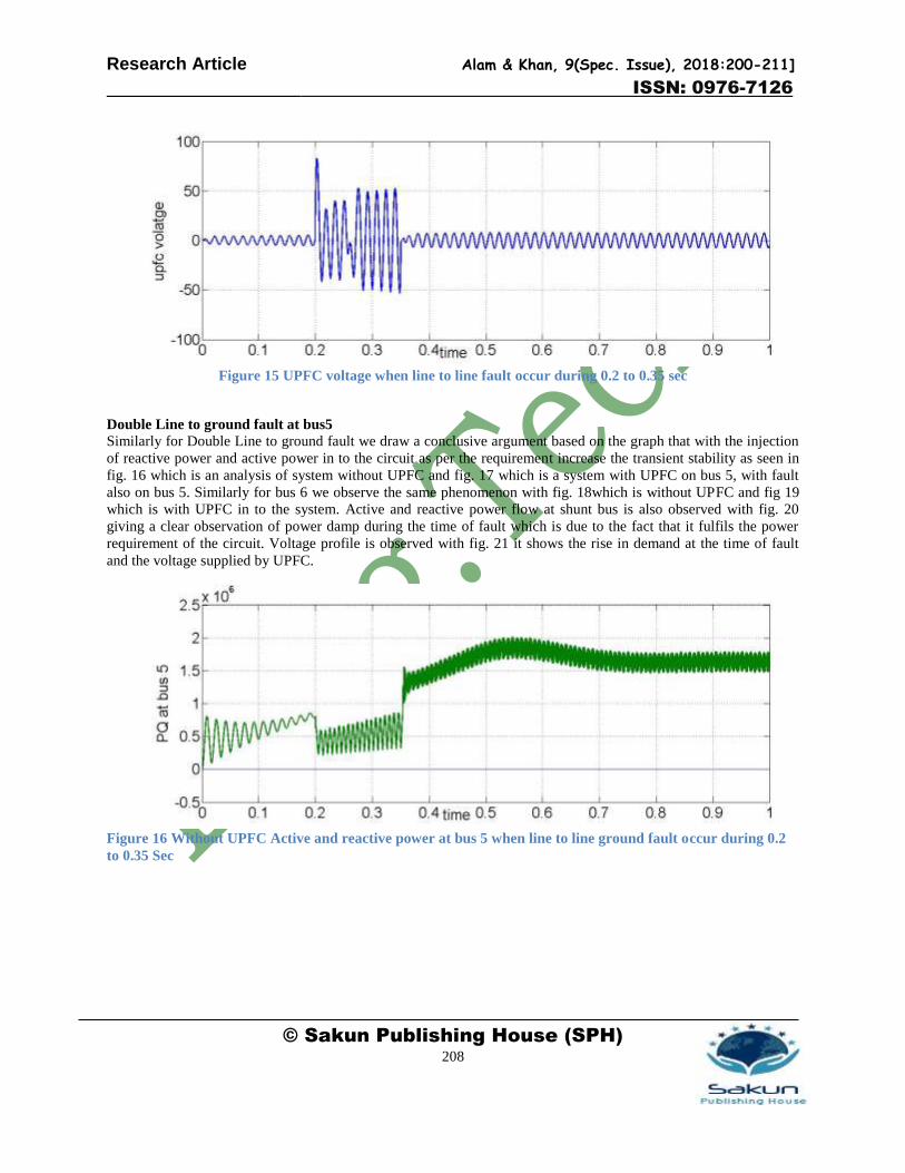
Figure 15 UPFC voltage when line to line fault occur during 0.2 to 0.35 sec
Double Line to ground fault at bus5
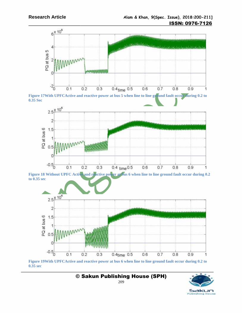
Similarly for Double Line to ground fault we draw a conclusive argument based on the graph that with the injection
of reactive power and active power in to the circuit as per the requirement increase the transient stability as seen in
fig. 16 which is an analysis of system without UPFC and fig. 17 which is a system with UPFC on bus 5, with fault
also on bus 5. Similarly for bus 6 we observe the same phenomenon with fig. 18which is without UPFC and fig 19
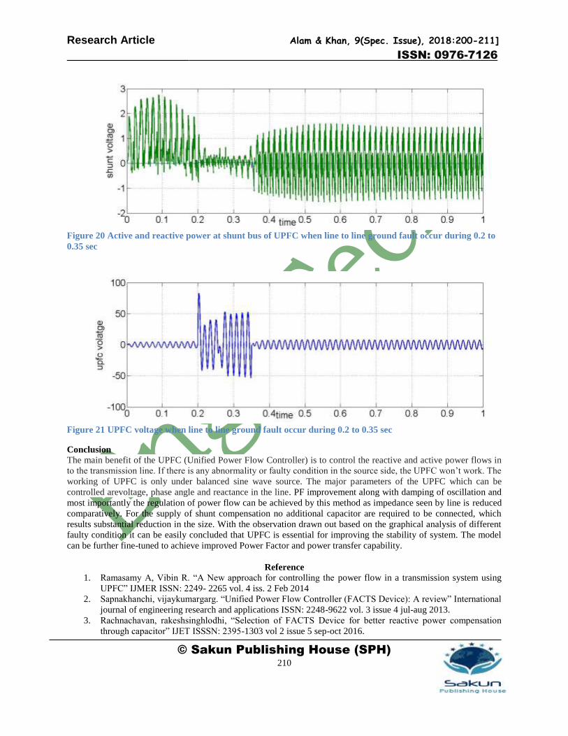
which is with UPFC in to the system. Active and reactive power flow at shunt bus is also observed with fig. 20
giving a clear observation of power damp during the time of fault which is due to the fact that it fulfils the power
requirement of the circuit. Voltage profile is observed with fig. 21 it shows the rise in demand at the time of fault
and the voltage supplied by UPFC.
Figure 16 Without UPFC Active and reactive power at bus 5 when line to line ground fault occur during 0.2
to 0.35 Sec
Research Article Alam & Khan, 9(Spec. Issue), 2018:200-211]
ISSN: 0976-7126
© Sakun Publishing House (SPH) 209
Figure 17With UPFCActive and reactive power at bus 5 when line to line ground fault occur during 0.2 to
0.35 Sec
Figure 18 Without UPFC Active and reactive power at bus 6 when line to line ground fault occur during 0.2
to 0.35 sec
Figure 19With UPFCActive and reactive power at bus 6 when line to line ground fault occur during 0.2 to
0.35 sec
Research Article Alam & Khan, 9(Spec. Issue), 2018:200-211]
ISSN: 0976-7126
© Sakun Publishing House (SPH) 210
Figure 20 Active and reactive power at shunt bus of UPFC when line to line ground fault occur during 0.2 to
0.35 sec
Figure 21 UPFC voltage when line to line ground fault occur during 0.2 to 0.35 sec
Conclusion
The main benefit of the UPFC (Unified Power Flow Controller) is to control the reactive and active power flows in
to the transmission line. If there is any abnormality or faulty condition in the source side, the UPFC won’t work. The
working of UPFC is only under balanced sine wave source. The major parameters of the UPFC which can be
controlled arevoltage, phase angle and reactance in the line. PF improvement along with damping of oscillation and
most importantly the regulation of power flow can be achieved by this method as impedance seen by line is reduced
comparatively. For the supply of shunt compensation no additional capacitor are required to be connected, which
results substantial reduction in the size. With the observation drawn out based on the graphical analysis of different
faulty condition it can be easily concluded that UPFC is essential for improving the stability of system. The model
can be further fine-tuned to achieve improved Power Factor and power transfer capability.
Reference
1. Ramasamy A, Vibin R. “A New approach for controlling the power flow in a transmission system using
UPFC” IJMER ISSN: 2249- 2265 vol. 4 iss. 2 Feb 2014
2. Sapnakhanchi, vijaykumargarg. “Unified Power Flow Controller (FACTS Device): A review” International
journal of engineering research and applications ISSN: 2248-9622 vol. 3 issue 4 jul-aug 2013.
3. Rachnachavan, rakeshsinghlodhi, “Selection of FACTS Device for better reactive power compensation
through capacitor” IJET ISSSN: 2395-1303 vol 2 issue 5 sep-oct 2016.

Research Article Alam & Khan, 9(Spec. Issue), 2018:200-211]
ISSN: 0976-7126
© Sakun Publishing House (SPH) 211
4. Hingorani“Understanding FACTS concept and technology- Flow and Stability Considerations of a
Transmission Interconnection” ISBN 0-7803-3455-8 IEEE Order No. PC571-3
5. K.R.PADIYAR “FACTS Controllers in Power transmission and distribution system”- Unified power flow
convertor and other multi-convertor device- pg no.-243.
6. MehrdadAhmadiKamarposhti and Hamid Lesani; Effects of STATCOM, TCSC, SSSC and UPFC on static
voltage stability”, 6 nov 2010 in Springer-Verlag.
7. Narain G Hingorani, Lazlo Gyugyi “Understanding FACTS- concept and technology of flexible AC
transmission system” – combined compensator UPFC and IPFC-Pg no. 324,” ISBN 0-7803-3455-8 IEEE
Order No. PC571-3.
8. Static Synchronous Series Compensator: A Solid-state Approach to the Series Compensation of
Transmission Lines, L. Gyugyi, C. D. Schauder and K. K. Sen, 96 WM 120-6 PWRD, IEEE PES Winter
Meeting, 1996.
9. P. Hari Krishnan, P. j. Ragu “Controlling power flow losses in UPFC system using Adaptive neuro- fuzzy
controller” IJRET eISSN: 2319-1163 pISSN: 2321- 7308 vol 3 may 2014.
10. Mihirrathod, IJIRST –International Journal for Innovative Research in Science & Technology| Volume 2 |
Issue 12 | May 2016 ISSN (online): 2349-6010.