up1/2/3/4/5/6/7 universal pneumatic rotary actuator
TRANSCRIPT
M
Hp
W—
—
Ea—
Co—
Su—
easurement made
Data sheet DS/A/UP–EN Rev K
Models UP1/2/3/4Universal pneuma
easy
/5/6/7tic rotary actuators
igh performance actuators for recision damper control
ide range of torque ratingsSeven actuator sizes available in ratings from 122 to 7320 Newton meter (90 to 5400 foot-pounds).12745 Newton meter (9400 foot-pounds) with Master-slave solution.
sy and flexible installationPlace in convenient locations and connect to driven device by standard linkage components.
ntrol modes for safe operationOptions available for fail-safe or fail-in-place on loss of control input and air supply.
itable for high temperature environmentsUse in ambient temperatures up to 85 ºC (185 ºF), depending on control input.
Ash—
C—
M—
W—
djustable relationship between control signal and output aft positionAdjusts easily with use of standard positioner characteristics: linear, square and square root relationship or custom-characteristics.
onventional or digital positioner optionsComplete range of control signal options including EDP300 and TZIDC digital positioner with HART© communications.
anual operationQuick and smooth transfer shifts easily from automatic to manual control.
ide range of options availableFactory installed IP66 (NEMA 4X) enclosure, pneumatic or electric position transmitter, alarm/travel switches, air failure lock option and heated enclosures available.
Models UP1/2/3/4/5/6/7Universal pneumatic rotary actuators
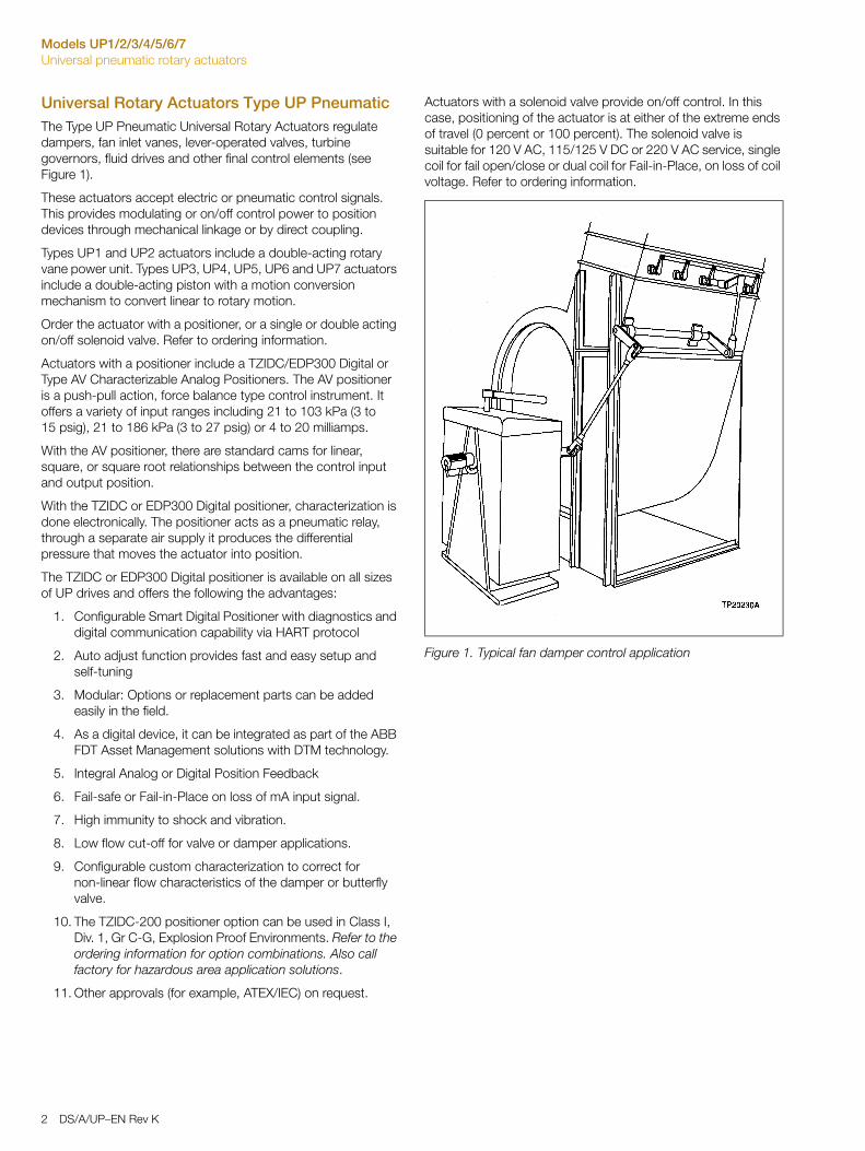
Universal Rotary Actuators Type UP PneumaticThe Type UP Pneumatic Universal Rotary Actuators regulate dampers, fan inlet vanes, lever-operated valves, turbine governors, fluid drives and other final control elements (see Figure 1).
These actuators accept electric or pneumatic control signals. This provides modulating or on/off control power to position devices through mechanical linkage or by direct coupling.
Types UP1 and UP2 actuators include a double-acting rotary vane power unit. Types UP3, UP4, UP5, UP6 and UP7 actuators include a double-acting piston with a motion conversion mechanism to convert linear to rotary motion.
Order the actuator with a positioner, or a single or double acting on/off solenoid valve. Refer to ordering information.
Actuators with a positioner include a TZIDC/EDP300 Digital or Type AV Characterizable Analog Positioners. The AV positioner is a push-pull action, force balance type control instrument. It offers a variety of input ranges including 21 to 103 kPa (3 to 15 psig), 21 to 186 kPa (3 to 27 psig) or 4 to 20 milliamps.
With the AV positioner, there are standard cams for linear, square, or square root relationships between the control input and output position.
With the TZIDC or EDP300 Digital positioner, characterization is done electronically. The positioner acts as a pneumatic relay, through a separate air supply it produces the differential pressure that moves the actuator into position.
The TZIDC or EDP300 Digital positioner is available on all sizes of UP drives and offers the following the advantages:
1. Configurable Smart Digital Positioner with diagnostics and digital communication capability via HART protocol
2. Auto adjust function provides fast and easy setup and self-tuning
3. Modular: Options or replacement parts can be added easily in the field.
4. As a digital device, it can be integrated as part of the ABB FDT Asset Management solutions with DTM technology.
5. Integral Analog or Digital Position Feedback
6. Fail-safe or Fail-in-Place on loss of mA input signal.
7. High immunity to shock and vibration.
8. Low flow cut-off for valve or damper applications.
9. Configurable custom characterization to correct for non-linear flow characteristics of the damper or butterfly valve.
10. The TZIDC-200 positioner option can be used in Class I, Div. 1, Gr C-G, Explosion Proof Environments. Refer to the ordering information for option combinations. Also call factory for hazardous area application solutions.
11. Other approvals (for example, ATEX/IEC) on request.
Actuators with a solenoid valve provide on/off control. In this case, positioning of the actuator is at either of the extreme ends of travel (0 percent or 100 percent). The solenoid valve is suitable for 120 V AC, 115/125 V DC or 220 V AC service, single coil for fail open/close or dual coil for Fail-in-Place, on loss of coil voltage. Refer to ordering information.
Figure 1. Typical fan damper control application
2 DS/A/UP–EN Rev K
Models UP1/2/3/4/5/6/7Universal pneumatic rotary actuators
Engineering Specifications
Supply Pressure (minimum and maximum)276 to 690 kPa (40 to 100 psig) with EDP300 and AV Positioners
276 to 621 kPa (40 to 90 psig) with TZIDC Positioners
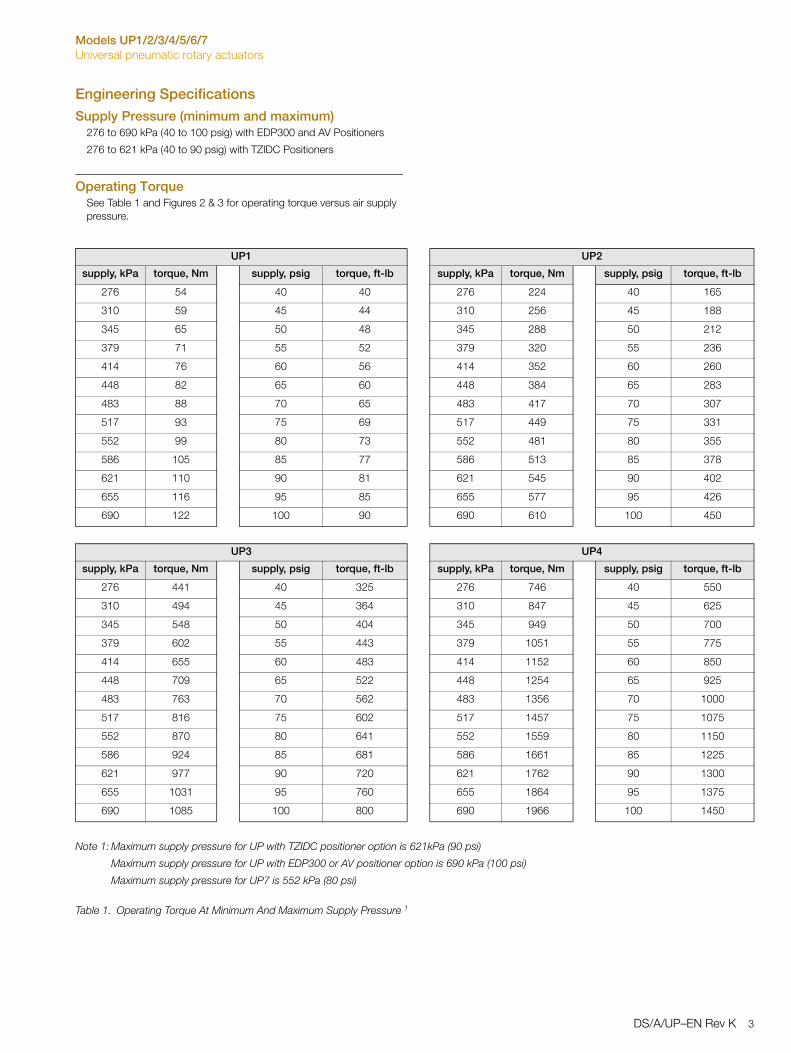
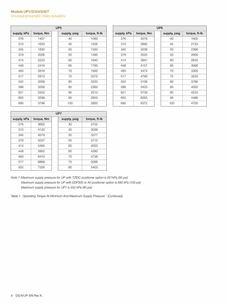
Operating TorqueSee Table 1 and Figures 2 & 3 for operating torque versus air supply pressure.
UP1 UP2
supply, kPa torque, Nm supply, psig torque, ft-lb supply, kPa torque, Nm supply, psig torque, ft-lb
276 54 40 40 276 224 40 165
310 59 45 44 310 256 45 188
345 65 50 48 345 288 50 212
379 71 55 52 379 320 55 236
414 76 60 56 414 352 60 260
448 82 65 60 448 384 65 283
483 88 70 65 483 417 70 307
517 93 75 69 517 449 75 331
552 99 80 73 552 481 80 355
586 105 85 77 586 513 85 378
621 110 90 81 621 545 90 402
655 116 95 85 655 577 95 426
690 122 100 90 690 610 100 450
UP3 UP4
supply, kPa torque, Nm supply, psig torque, ft-lb supply, kPa torque, Nm supply, psig torque, ft-lb
276 441 40 325 276 746 40 550
310 494 45 364 310 847 45 625
345 548 50 404 345 949 50 700
379 602 55 443 379 1051 55 775
414 655 60 483 414 1152 60 850
448 709 65 522 448 1254 65 925
483 763 70 562 483 1356 70 1000
517 816 75 602 517 1457 75 1075
552 870 80 641 552 1559 80 1150
586 924 85 681 586 1661 85 1225
621 977 90 720 621 1762 90 1300
655 1031 95 760 655 1864 95 1375
690 1085 100 800 690 1966 100 1450
Note 1: Maximum supply pressure for UP with TZIDC positioner option is 621kPa (90 psi)
Maximum supply pressure for UP with EDP300 or AV positioner option is 690 kPa (100 psi)
Maximum supply pressure for UP7 is 552 kPa (80 psi)
Table 1. Operating Torque At Minimum And Maximum Supply Pressure 1
DS/A/UP–EN Rev K 3
Models UP1/2/3/4/5/6/7Universal pneumatic rotary actuators
UP5 UP6
supply, kPa torque, Nm supply, psig torque, ft-lb supply, kPa torque, Nm supply, psig torque, ft-lb
276 1437 40 1060 276 2576 40 1900
310 1633 45 1205 310 2892 45 2133
345 1830 50 1350 345 3208 50 2366
379 2026 55 1495 379 3525 55 2600
414 2223 60 1640 414 3841 60 2833
448 2419 65 1785 448 4157 65 3066
483 2616 70 1930 483 4474 70 3300
517 2813 75 2075 517 4790 75 3533
552 3009 80 2220 552 5106 80 3766
586 3206 85 2365 586 5423 85 4000
621 3402 90 2510 621 5739 90 4233
655 3599 95 2655 655 6055 95 4466
690 3796 100 2800 690 6372 100 4700
UP7
supply, kPa torque, Nm supply, psig torque, ft-lb
276 3663 40 2702
310 4120 45 3039
345 4579 50 3377
379 5037 55 3715
414 5495 60 4053
448 5952 65 4390
483 6410 70 4728
517 6869 75 5066
552 7326 80 5403
Note 1: Maximum supply pressure for UP with TZIDC positioner option is 621kPa (90 psi)
Maximum supply pressure for UP with EDP300 or AV positioner option is 690 kPa (100 psi)
Maximum supply pressure for UP7 is 552 kPa (80 psi)
Table 1. Operating Torque At Minimum And Maximum Supply Pressure 1 (Continued)
4 DS/A/UP–EN Rev K

Models UP1/2/3/4/5/6/7Universal pneumatic rotary actuators
Figure 2. Operating Torque Versus Supply Pressure for Type UP1 & UP2 Actuators
Figure 3. Operating Torque Versus Supply Pressure for Types UP3 thru UP6 Actuators
DS/A/UP–EN Rev K 5
Models UP1/2/3/4/5/6/7Universal pneumatic rotary actuators
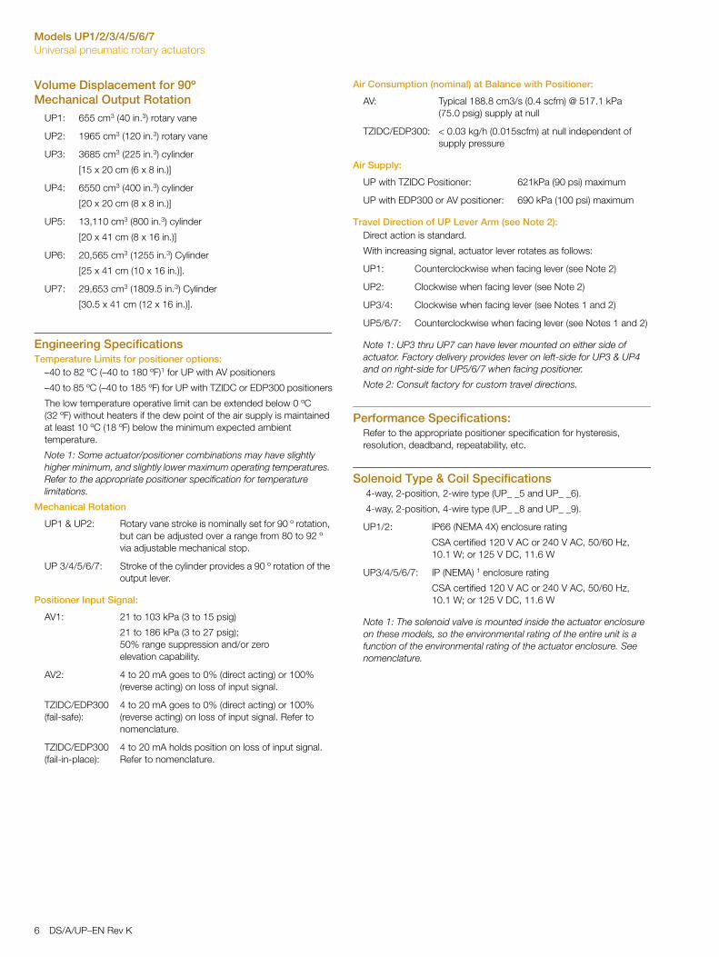
Volume Displacement for 90º Mechanical Output Rotation
Engineering SpecificationsTemperature Limits for positioner options:
–40 to 82 ºC (–40 to 180 ºF)1 for UP with AV positioners
–40 to 85 ºC (–40 to 185 ºF) for UP with TZIDC or EDP300 positioners
The low temperature operative limit can be extended below 0 ºC (32 ºF) without heaters if the dew point of the air supply is maintained at least 10 ºC (18 ºF) below the minimum expected ambient temperature.
Note 1: Some actuator/positioner combinations may have slightly higher minimum, and slightly lower maximum operating temperatures. Refer to the appropriate positioner specification for temperature limitations.
Mechanical Rotation
Positioner Input Signal:
Air Consumption (nominal) at Balance with Positioner:
Air Supply:
Travel Direction of UP Lever Arm (see Note 2):Direct action is standard.
With increasing signal, actuator lever rotates as follows:
Note 1: UP3 thru UP7 can have lever mounted on either side of actuator. Factory delivery provides lever on left-side for UP3 & UP4 and on right-side for UP5/6/7 when facing positioner.
Note 2: Consult factory for custom travel directions.
Performance Specifications:Refer to the appropriate positioner specification for hysteresis, resolution, deadband, repeatability, etc.
Solenoid Type & Coil Specifications 4-way, 2-position, 2-wire type (UP_ _5 and UP_ _6).
4-way, 2-position, 4-wire type (UP_ _8 and UP_ _9).
Note 1: The solenoid valve is mounted inside the actuator enclosure on these models, so the environmental rating of the entire unit is a function of the environmental rating of the actuator enclosure. See nomenclature.
UP1: 655 cm3 (40 in.3) rotary vane
UP2: 1965 cm3 (120 in.3) rotary vane
UP3: 3685 cm3 (225 in.3) cylinder
[15 x 20 cm (6 x 8 in.)]
UP4: 6550 cm3 (400 in.3) cylinder
[20 x 20 cm (8 x 8 in.)]
UP5: 13,110 cm3 (800 in.3) cylinder
[20 x 41 cm (8 x 16 in.)]
UP6: 20,565 cm3 (1255 in.3) Cylinder
[25 x 41 cm (10 x 16 in.)].
UP7: 29,653 cm3 (1809.5 in.3) Cylinder
[30.5 x 41 cm (12 x 16 in.)].
UP1 & UP2: Rotary vane stroke is nominally set for 90 º rotation, but can be adjusted over a range from 80 to 92 º via adjustable mechanical stop.
UP 3/4/5/6/7: Stroke of the cylinder provides a 90 º rotation of the output lever.
AV1: 21 to 103 kPa (3 to 15 psig)
21 to 186 kPa (3 to 27 psig); 50% range suppression and/or zero elevation capability.
AV2: 4 to 20 mA goes to 0% (direct acting) or 100% (reverse acting) on loss of input signal.
TZIDC/EDP300 (fail-safe):
4 to 20 mA goes to 0% (direct acting) or 100% (reverse acting) on loss of input signal. Refer to nomenclature.
TZIDC/EDP300 (fail-in-place):
4 to 20 mA holds position on loss of input signal. Refer to nomenclature.
AV: Typical 188.8 cm3/s (0.4 scfm) @ 517.1 kPa (75.0 psig) supply at null
TZIDC/EDP300: < 0.03 kg/h (0.015scfm) at null independent of supply pressure
UP with TZIDC Positioner: 621kPa (90 psi) maximum
UP with EDP300 or AV positioner: 690 kPa (100 psi) maximum
UP1: Counterclockwise when facing lever (see Note 2)
UP2: Clockwise when facing lever (see Note 2)
UP3/4: Clockwise when facing lever (see Notes 1 and 2)
UP5/6/7: Counterclockwise when facing lever (see Notes 1 and 2)
UP1/2: IP66 (NEMA 4X) enclosure rating
CSA certified 120 V AC or 240 V AC, 50/60 Hz,10.1 W; or 125 V DC, 11.6 W
UP3/4/5/6/7: IP (NEMA) 1 enclosure rating
CSA certified 120 V AC or 240 V AC, 50/60 Hz, 10.1 W; or 125 V DC, 11.6 W
6 DS/A/UP–EN Rev K
Models UP1/2/3/4/5/6/7Universal pneumatic rotary actuators
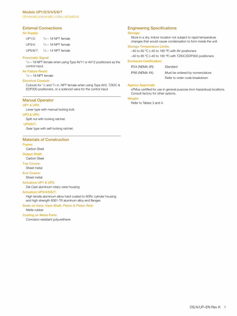
External ConnectionsAir Supply:
Pneumatic Signal:1/4 – 18 NPT female when using Type AV11 or AV12 positioners as the control input.
Air Failure Reset:1/4 – 18 NPT female
Electrical Conduit:Cutouts for 1/2 and 3/4 in. NPT female when using Type AV2, TZIDC & EDP300 positioners, or a solenoid valve for the control input
Manual OperatorUP1 & UP2:
Lever type with manual locking bolt.
UP3 & UP4:Split nut with locking ratchet.
UP5/6/7:Gear type with self-locking ratchet.
Materials of ConstructionFrame:
Carbon Steel
Output Shaft:Carbon Steel
Top Covers:Sheet metal
End Covers:Sheet metal
Actuators UP1 & UP2: Die Cast aluminum rotary vane housing
Actuators UP3/4/5/6/7:High tensile aluminum allow hard coated to 60Rc cylinder housing and high strength 6061-T6 aluminum alloy end flanges
Seals on Vane, Vane Shaft, Piston & Piston Rod:Nitrile rubber
Coating on Metal Parts:Corrosion-resistant polyurethane
Engineering Specifications Storage:
Store in a dry, indoor location not subject to rapid temperature changes that would cause condensation to form inside the unit.
Storage Temperature Limits:–40 to 82 ºC (–40 to 180 ºF) with AV positioners
–40 to 85 ºC (–40 to 185 ºF) with TZIDC/EDP300 positioners
Enclosure Certification:
Agency Approvals: cFMus certified for use in general purpose (non-hazardous) locations. Consult factory for other options.
Weight:Refer to Tables 3 and 4.
UP1/2: 1/4 – 18 NPT female
UP3/4: 1/4 – 18 NPT female
UP5/6/7: 1/2 – 14 NPT female
IP24 (NEMA 3R): Standard
IP66 (NEMA 4X): Must be ordered by nomenclature
Refer to order code breakdown
DS/A/UP–EN Rev K 7
Models UP1/2/3/4/5/6/7Universal pneumatic rotary actuators
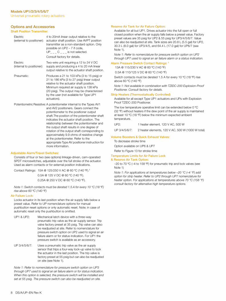
Options and Accessories Shaft Position Transmitter:
Adjustable Alarm/Travel Switches:Consists of four or two (see options) linkage-driven, cam-operated SPDT microswitches, adjustable over the full stroke of the actuator. Used as alarm contacts or for external position indications.
Note 1: Switch contacts must be derated 1.5 A for every 10 °C (18 ºF) rise above 60 ºC (140 ºF)
Air Failure Lock:Locks actuator in its last position when the air supply falls below a preset value. Refer to UP nomenclature options for manual pushbutton reset options or only automatic reset. Note; in case of automatic reset only the pushbutton is omitted.
Note 1: Refer to nomenclature for pressure switch option on UP3 through UP7 used to signal an air failure alarm or for status indication. When this option is selected, the pressure switch will be installed and set at 55 psig. The pressure switch can also be readjusted on site.
Reserve Air Tank for Air Failure Option: Available for all but UP1. Drives actuator into the full open or full closed position when the air supply falls below a preset value. Factory preset values are 35 psig for UP2 & 55 psig for UP3/4/5/6/7. Value can also be readjusted at site. Tank sizes are 20.8 L (5.5 gal) for UP2, 30.3 L (8.0 gal) for UP3/4/5, and 64.4 L (17.0 gal) for UP6/7 (see Note 1).
Note 1: Refer to nomenclature for pressure switch option on UP2 through UP7 used to signal an air failure alarm or a status indication.
Alarm Pressure Switch Contact Ratings: 1
13A @ 115/230 V AC @ 60 ºC (140 ºF)
0.5A @ 110/125 V DC @ 60 ºC (140 ºF)
Switch contacts must be derated 1.5 A for every 10 ºC (18 ºF) rise above 60 ºC (140 ºF)
Note 1: Not available in combination with TZIDC-200 Explosion-Proof Positioner. Consult factory for details.
Strip Heaters (Thermostatically Controlled)Available for all except Type UP1 actuators and UPs with Explosion Proof TZIDC-200 Positioner.
The low temperature operative limit can be extended below 0 ºC (32 ºF) without heaters if the dew point of the air supply is maintained at least 10 ºC (18 ºF) below the minimum expected ambient temperature.
Volume Boosters & Quick Exhaust Valves:To decrease stroke time
Option available on UP6 & UP7
Refer to Figure 13 for stroke time
Temperature Limits for Air Failure Lock & Reserve Air Tank Option:
–20 to 70 ºC (–4 to 158 ºF) for pneumatic trip and lock valves (see Note 1)
Note 1: For applications at temperatures below –20 °C (–4 °F) add option for strip heater. Refer to UP2 through UP7 nomenclature for heater option. For applications at temperatures above 70 °C (158 °F) consult factory for alternative high temperature options.
Electric (external to positioner):
4 to 20mA linear output relative to the actuator shaft position. Use AVPT position transmitter as a non-standard option. Only possible on UP2 – 7 if code, UP_ _ _ C _ _ _ is not selected.
Consult factory for details.
Electric (internal to positioner):
Two-wire unit requiring a 12 to 24 V DC supply and producing a 4 to 20 mA linear output relative to the actuator shaft position.
Pneumatic: Produces a 21 to 103 kPa (3 to 15 psig) or 21 to 186 kPa (3 to 27 psig) linear output relative to the actuator shaft position. Minimum required air supply is 138 kPa (20 psig). The output may be characterized by the user (not available for Type UP1 actuators).
Potentiometric Resistive: A potentiometer internal to the Types AV1 and AV2 positioners. Gears connect the potentiometer to the positioner output shaft.The position of the potentiometer shaft indicates the actuator shaft position. The relationship between the potentiometer and the output shaft results in one degree of rotation of the output shaft corresponding to approximately 9.9 ohms of resistive change at the potentiometer. Refer to the appropriate Type AV positioner instruction for more information.
Contact Ratings: 15A @ 125/250 V AC @ 60 ºC (140 ºF).1
0.5A @ 125 V DC @ 60 ºC (140 ºF).
0.25A @ 250 V DC @ 60 ºC (140 ºF).
UP1 & UP2: Mechanical latch device with a three-way pneumatic trip valve as the air supply sensor. Trip valve factory preset at 35 psig. Trip valve can also be readjusted at site. Refer to nomenclature for pressure switch option on UP2 used to signal an air failure alarm or for status indication. For UP1 the pressure switch is available as an accessory.
UP 3/4/5/6/7: Uses a pneumatic trip valve as the air supply sensor that trips a four-way lock-up valve to lock the actuator in the last position. The trip valve is factory preset at 55 psig but can also be readjusted on site (see Note 1).
UP2: 1 heater element, 120 V AC, 500 W
UP 3/4/5/6/7: 2 heater elements, 120 V AC, 500 W (1000 W total)
8 DS/A/UP–EN Rev K
Models UP1/2/3/4/5/6/7Universal pneumatic rotary actuators
AccessoriesCoalescing Filter/Regulator for UP3/4/5/6/7:
Part No. 1951439D1
Parker No. 12E37E18AA & PS807P
Auto float drain1/2 in. NPT connections
1132 l/m (40 scfm) capacity
17 barg (250 psig) maximum inlet
8.6 barg (125 psig) maximum outlet
with mounting bracket
Coalescing Filter for UP1 & UP2: Part No. 5328563D2
Parker No. 11F18EC
Auto float drain1/4 in. NPT connections
1274 l/m (45 scfm) capacity
17 barg (250 psig) maximum inlet
Regulator with Gage for UP1 & UP2:Part No. 1951029D5
Parker No. 06R118AC1/4 in. NPT connection
1500 l/m (53 scfm) capacity
17 barg (250 psig) maximum inlet
8.6 barg (125 psig) maximum outlet
Pressure Switch:Part No. 1941099A2
Pressure Gages:Instrument signal (3 to 15 psi) for AV1 positioner
Output pressure for AV, TZIDC & EDP300
Part No. 5326605A4 (Instrument one required)
Part No. 5326605A6 (Output, two required).
Speed Control:Regulates time constant of positioner and final control element. Orifices installed directly into the positioner output ports (only for AV positioners).
Part No. 5327327A1: 1 mm (0.04 in.).
Part No. 5327327A2: Blank – Drill to suit.
For TZIDC & EDP300 positioners the speed control is electronically adjustable.
(Refer to TZIDC & EDP300 configuration)
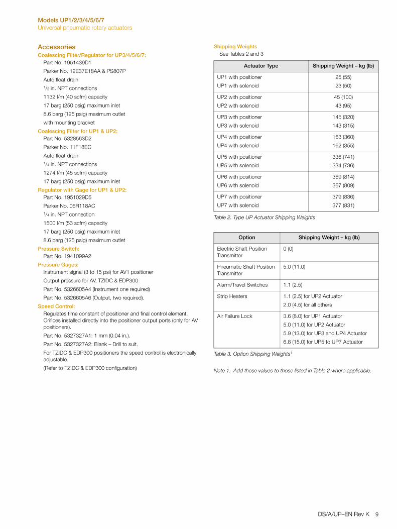
Shipping WeightsSee Tables 2 and 3
Note 1: Add these values to those listed in Table 2 where applicable.
Actuator Type Shipping Weight – kg (lb)
UP1 with positioner
UP1 with solenoid
25 (55)
23 (50)
UP2 with positioner
UP2 with solenoid
45 (100)
43 (95)
UP3 with positioner
UP3 with solenoid
145 (320)
143 (315)
UP4 with positioner
UP4 with solenoid
163 (360)
162 (355)
UP5 with positioner
UP5 with solenoid
336 (741)
334 (736)
UP6 with positioner
UP6 with solenoid
369 (814)
367 (809)
UP7 with positioner
UP7 with solenoid
379 (836)
377 (831)
Table 2. Type UP Actuator Shipping Weights
Option Shipping Weight – kg (lb)
Electric Shaft Position Transmitter
0 (0)
Pneumatic Shaft Position Transmitter
5.0 (11.0)
Alarm/Travel Switches 1.1 (2.5)
Strip Heaters 1.1 (2.5) for UP2 Actuator
2.0 (4.5) for all others
Air Failure Lock 3.6 (8.0) for UP1 Actuator
5.0 (11.0) for UP2 Actuator
5.9 (13.0) for UP3 and UP4 Actuator
6.8 (15.0) for UP5 to UP7 Actuator
Table 3. Option Shipping Weights1
DS/A/UP–EN Rev K 9
Models UP1/2/3/4/5/6/7Universal pneumatic rotary actuators
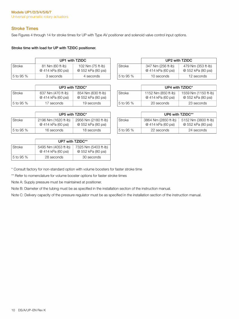
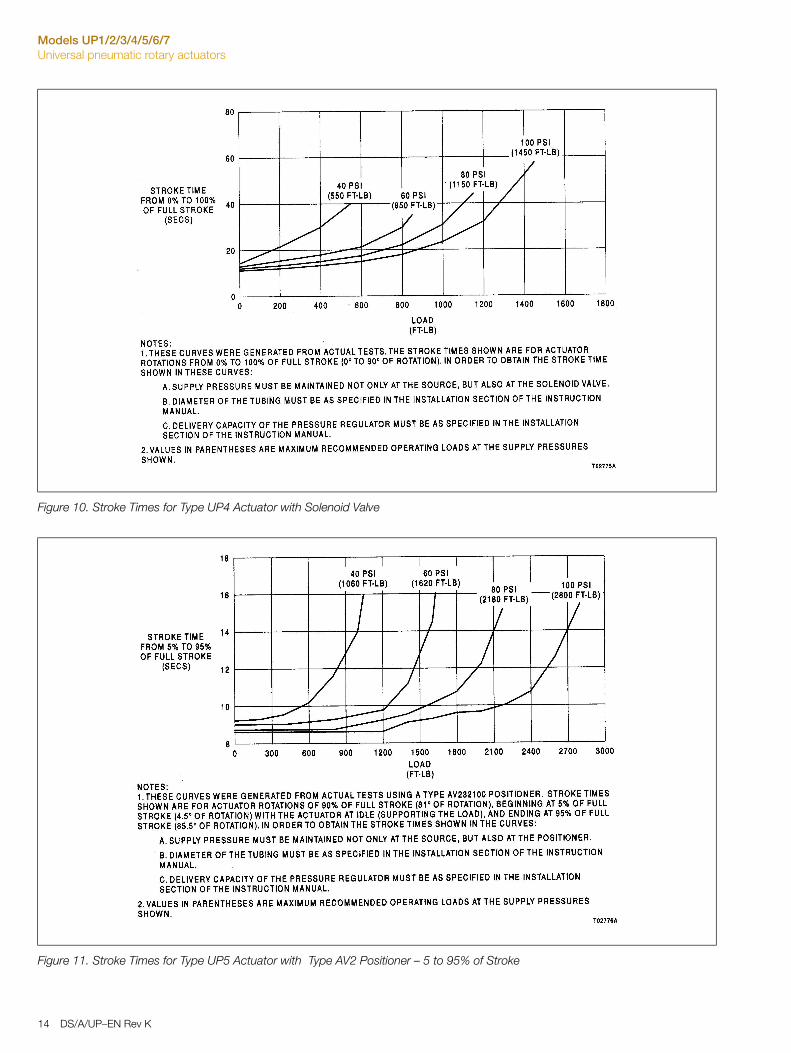
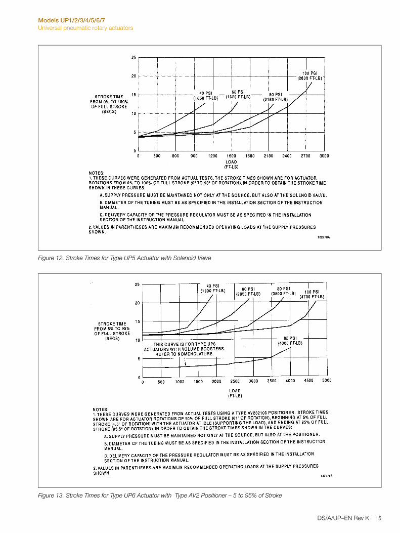
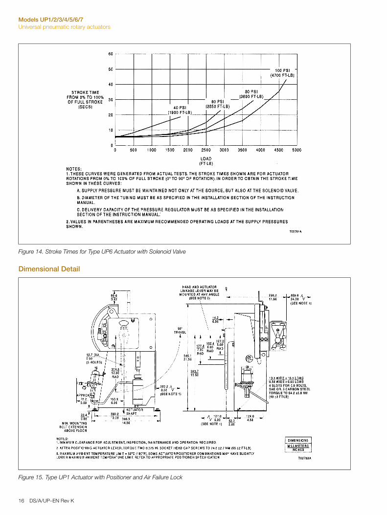
Stroke TimesSee Figures 4 through 14 for stroke times for UP with Type AV positioner and solenoid valve control input options.
Stroke time with load for UP with TZIDC positioner.
* Consult factory for non-standard option with volume boosters for faster stroke time
** Refer to nomenclature for volume booster options for faster stroke times
Note A: Supply pressure must be maintained at positioner.
Note B: Diameter of the tubing must be as specified in the installation section of the instruction manual.
Note C: Delivery capacity of the pressure regulator must be as specified in the installation section of the instruction manual.
UP1 with TZIDC UP2 with TZIDC
Stroke 81 Nm (60 ft-lb) @ 414 kPa (60 psi)
102 Nm (75 ft-lb) @ 552 kPa (80 psi)
Stroke 347 Nm (256 ft-lb) @ 414 kPa (60 psi)
479 Nm (353 ft-lb) @ 552 kPa (80 psi)
5 to 95 % 3 seconds 4 seconds 5 to 95 % 10 seconds 12 seconds
UP3 with TZIDC* UP4 with TZIDC*
Stroke 637 Nm (470 ft-lb) @ 414 kPa (60 psi)
854 Nm (630 ft-lb) @ 552 kPa (80 psi)
Stroke 1152 Nm (850 ft-lb) @ 414 kPa (60 psi)
1559 Nm (1150 ft-lb) @ 552 kPa (80 psi)
5 to 95 % 17 seconds 19 seconds 5 to 95 % 20 seconds 23 seconds
UP5 with TZIDC* UP6 with TZIDC**
Stroke 2196 Nm (1620 ft-lb) @ 414 kPa (60 psi)
2956 Nm (2180 ft-lb) @ 552 kPa (80 psi)
Stroke 3864 Nm (2850 ft-lb) @ 414 kPa (60 psi)
5152 Nm (3800 ft-lb) @ 552 kPa (80 psi)
5 to 95 % 16 seconds 18 seconds 5 to 95 % 22 seconds 24 seconds
UP7 with TZIDC**
Stroke 5495 Nm (4053 ft-lb) @ 414 kPa (60 psi)
7325 Nm (5403 ft-lb) @ 552 kPa (80 psi)
5 to 95 % 28 seconds 30 seconds
10 DS/A/UP–EN Rev K
Models UP1/2/3/4/5/6/7Universal pneumatic rotary actuators
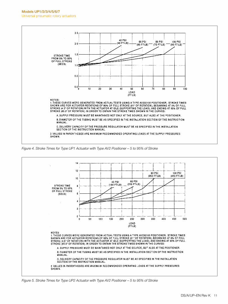
Figure 4. Stroke Times for Type UP1 Actuator with Type AV2 Positioner – 5 to 95% of Stroke
Figure 5. Stroke Times for Type UP2 Actuator with Type AV2 Positioner – 5 to 95% of Stroke
DS/A/UP–EN Rev K 11
Models UP1/2/3/4/5/6/7Universal pneumatic rotary actuators
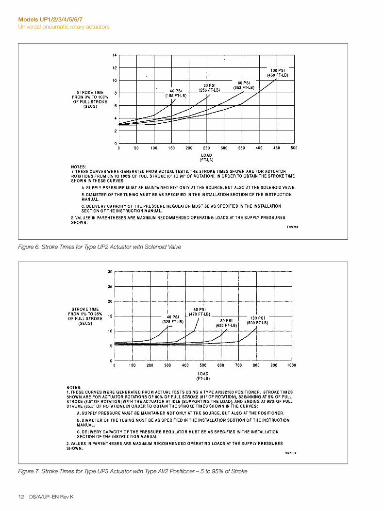
Figure 6. Stroke Times for Type UP2 Actuator with Solenoid Valve
Figure 7. Stroke Times for Type UP3 Actuator with Type AV2 Positioner – 5 to 95% of Stroke
12 DS/A/UP–EN Rev K
Models UP1/2/3/4/5/6/7Universal pneumatic rotary actuators
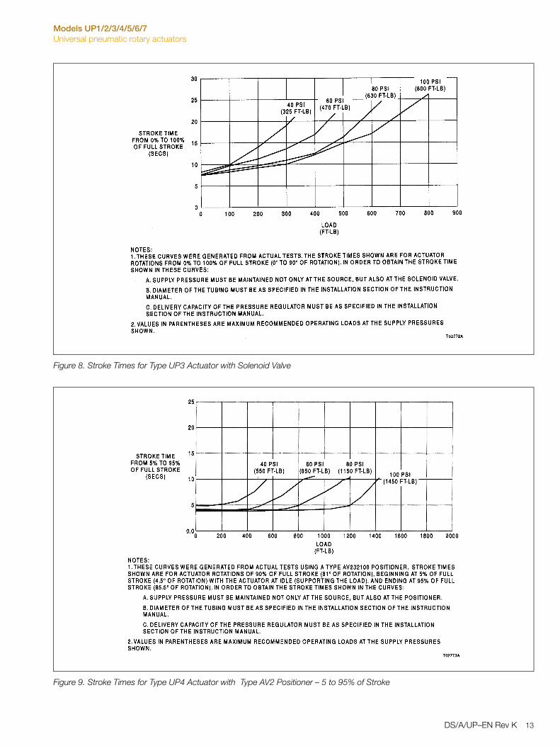
Figure 8. Stroke Times for Type UP3 Actuator with Solenoid Valve
Figure 9. Stroke Times for Type UP4 Actuator with Type AV2 Positioner – 5 to 95% of Stroke
DS/A/UP–EN Rev K 13
Models UP1/2/3/4/5/6/7Universal pneumatic rotary actuators
Figure 10. Stroke Times for Type UP4 Actuator with Solenoid Valve
Figure 11. Stroke Times for Type UP5 Actuator with Type AV2 Positioner – 5 to 95% of Stroke
14 DS/A/UP–EN Rev K
Models UP1/2/3/4/5/6/7Universal pneumatic rotary actuators
Figure 12. Stroke Times for Type UP5 Actuator with Solenoid Valve
Figure 13. Stroke Times for Type UP6 Actuator with Type AV2 Positioner – 5 to 95% of Stroke
DS/A/UP–EN Rev K 15
Models UP1/2/3/4/5/6/7Universal pneumatic rotary actuators
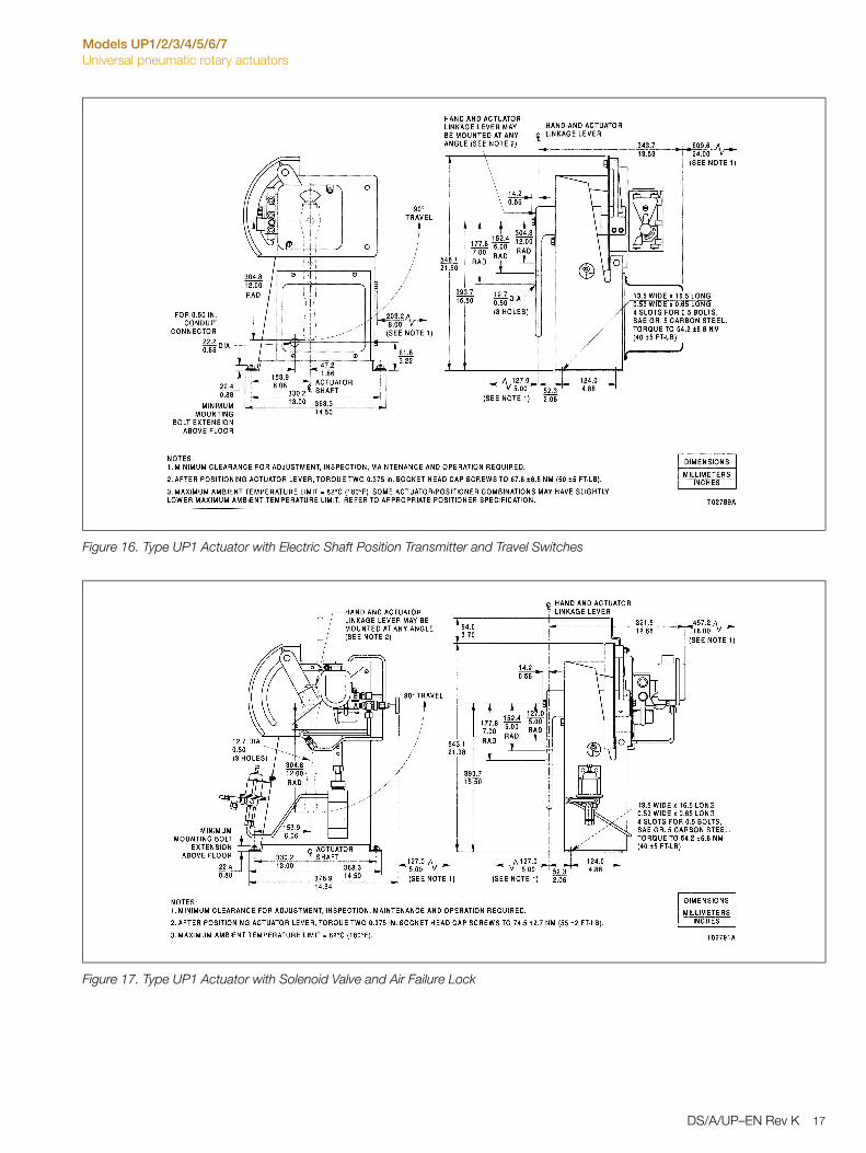
Dimensional Detail
Figure 14. Stroke Times for Type UP6 Actuator with Solenoid Valve
Figure 15. Type UP1 Actuator with Positioner and Air Failure Lock
16 DS/A/UP–EN Rev K
Models UP1/2/3/4/5/6/7Universal pneumatic rotary actuators
Figure 16. Type UP1 Actuator with Electric Shaft Position Transmitter and Travel Switches
Figure 17. Type UP1 Actuator with Solenoid Valve and Air Failure Lock
DS/A/UP–EN Rev K 17
Models UP1/2/3/4/5/6/7Universal pneumatic rotary actuators
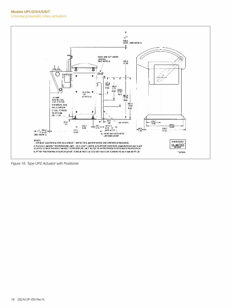
Figure 18. Type UP2 Actuator with Positioner
18 DS/A/UP–EN Rev K
Models UP1/2/3/4/5/6/7Universal pneumatic rotary actuators
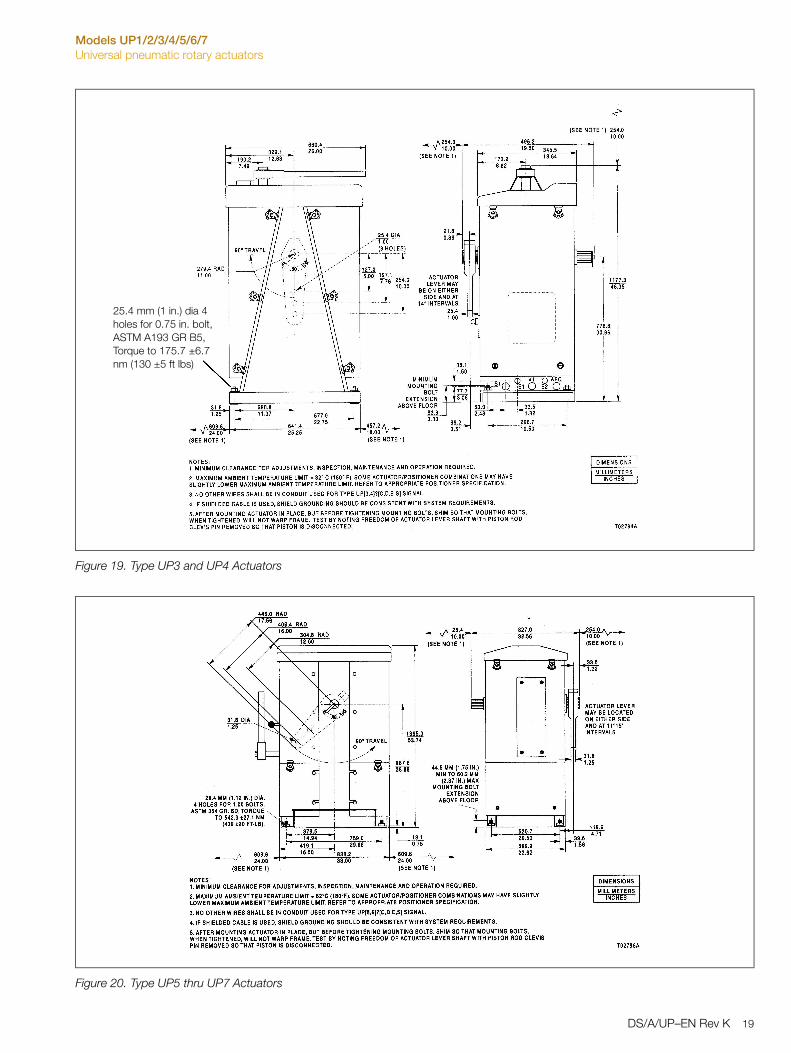
Figure 19. Type UP3 and UP4 Actuators
Figure 20. Type UP5 thru UP7 Actuators
25.4 mm (1 in.) dia 4 holes for 0.75 in. bolt, ASTM A193 GR B5, Torque to 175.7 ±6.7 nm (130 ±5 ft lbs)
DS/A/UP–EN Rev K 19
Models UP1/2/3/4/5/6/7Universal pneumatic rotary actuators
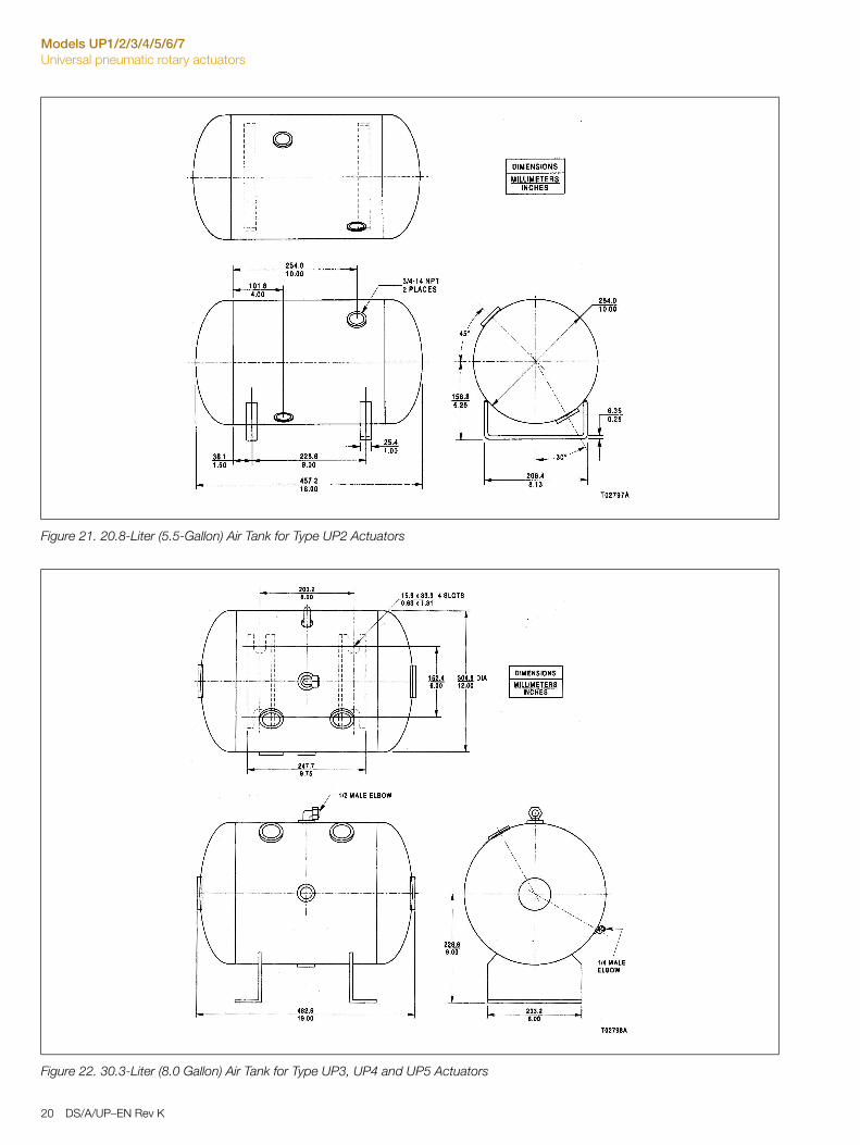
Figure 21. 20.8-Liter (5.5-Gallon) Air Tank for Type UP2 Actuators
Figure 22. 30.3-Liter (8.0 Gallon) Air Tank for Type UP3, UP4 and UP5 Actuators
20 DS/A/UP–EN Rev K
Models UP1/2/3/4/5/6/7Universal pneumatic rotary actuators
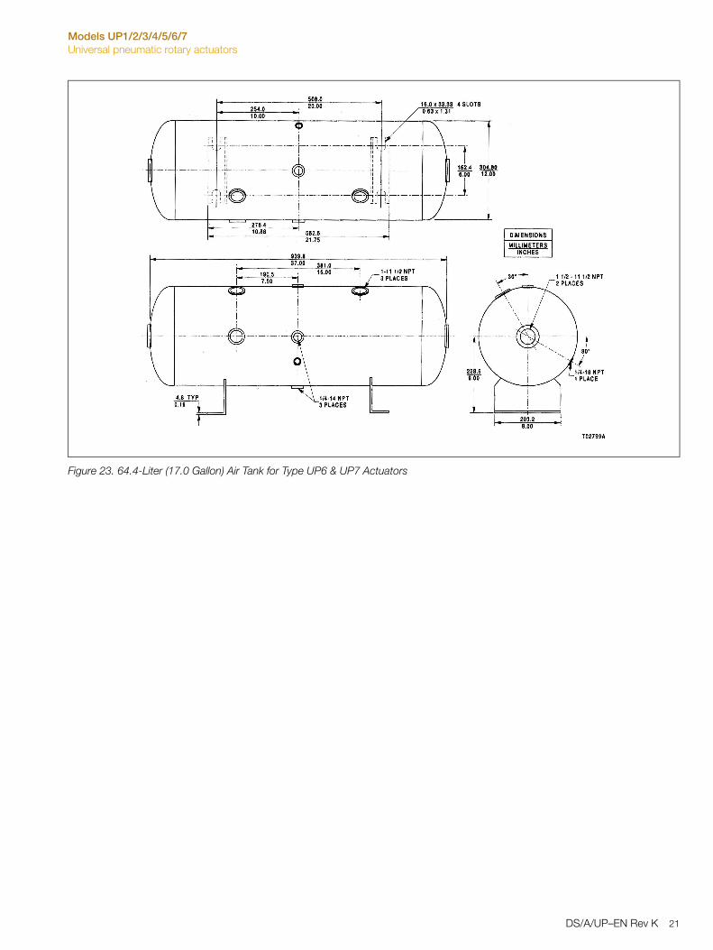
Figure 23. 64.4-Liter (17.0 Gallon) Air Tank for Type UP6 & UP7 Actuators
DS/A/UP–EN Rev K 21
Models UP1/2/3/4/5/6/7Universal pneumatic rotary actuators
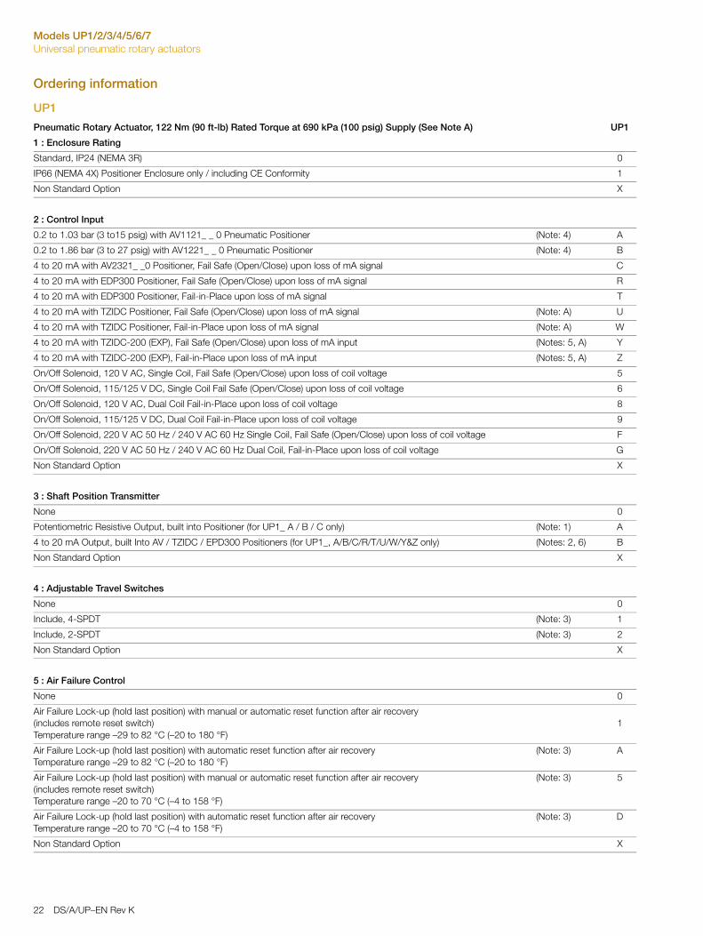
Ordering information
UP1
Pneumatic Rotary Actuator, 122 Nm (90 ft-lb) Rated Torque at 690 kPa (100 psig) Supply (See Note A) UP1
1 : Enclosure Rating
Standard, IP24 (NEMA 3R) 0
IP66 (NEMA 4X) Positioner Enclosure only / including CE Conformity 1
Non Standard Option X
2 : Control Input
0.2 to 1.03 bar (3 to15 psig) with AV1121_ _ 0 Pneumatic Positioner (Note: 4) A
0.2 to 1.86 bar (3 to 27 psig) with AV1221_ _ 0 Pneumatic Positioner (Note: 4) B
4 to 20 mA with AV2321_ _0 Positioner, Fail Safe (Open/Close) upon loss of mA signal C
4 to 20 mA with EDP300 Positioner, Fail Safe (Open/Close) upon loss of mA signal R
4 to 20 mA with EDP300 Positioner, Fail-in-Place upon loss of mA signal T
4 to 20 mA with TZIDC Positioner, Fail Safe (Open/Close) upon loss of mA signal (Note: A) U
4 to 20 mA with TZIDC Positioner, Fail-in-Place upon loss of mA signal (Note: A) W
4 to 20 mA with TZIDC-200 (EXP), Fail Safe (Open/Close) upon loss of mA input (Notes: 5, A) Y
4 to 20 mA with TZIDC-200 (EXP), Fail-in-Place upon loss of mA input (Notes: 5, A) Z
On/Off Solenoid, 120 V AC, Single Coil, Fail Safe (Open/Close) upon loss of coil voltage 5
On/Off Solenoid, 115/125 V DC, Single Coil Fail Safe (Open/Close) upon loss of coil voltage 6
On/Off Solenoid, 120 V AC, Dual Coil Fail-in-Place upon loss of coil voltage 8
On/Off Solenoid, 115/125 V DC, Dual Coil Fail-in-Place upon loss of coil voltage 9
On/Off Solenoid, 220 V AC 50 Hz / 240 V AC 60 Hz Single Coil, Fail Safe (Open/Close) upon loss of coil voltage F
On/Off Solenoid, 220 V AC 50 Hz / 240 V AC 60 Hz Dual Coil, Fail-in-Place upon loss of coil voltage G
Non Standard Option X
3 : Shaft Position Transmitter
None 0
Potentiometric Resistive Output, built into Positioner (for UP1_ A / B / C only) (Note: 1) A
4 to 20 mA Output, built Into AV / TZIDC / EPD300 Positioners (for UP1_, A/B/C/R/T/U/W/Y&Z only) (Notes: 2, 6) B
Non Standard Option X
4 : Adjustable Travel Switches
None 0
Include, 4-SPDT (Note: 3) 1
Include, 2-SPDT (Note: 3) 2
Non Standard Option X
5 : Air Failure Control
None 0
Air Failure Lock-up (hold last position) with manual or automatic reset function after air recovery (includes remote reset switch)Temperature range –29 to 82 °C (–20 to 180 °F)
1
Air Failure Lock-up (hold last position) with automatic reset function after air recovery Temperature range –29 to 82 °C (–20 to 180 °F)
(Note: 3) A
Air Failure Lock-up (hold last position) with manual or automatic reset function after air recovery (includes remote reset switch)Temperature range –20 to 70 °C (–4 to 158 °F)
(Note: 3) 5
Air Failure Lock-up (hold last position) with automatic reset function after air recovery Temperature range –20 to 70 °C (–4 to 158 °F)
(Note: 3) D
Non Standard Option X
22 DS/A/UP–EN Rev K
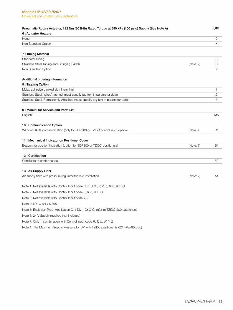
Models UP1/2/3/4/5/6/7Universal pneumatic rotary actuators
6 : Actuator Heaters
None 0
Non Standard Option X
7 : Tubing Material
Standard Tubing 0
Stainless Steel Tubing and Fittings (304SS) (Note: 2) S
Non Standard Option X
Additional ordering information
8 : Tagging Option
Mylar, adhesive backed aluminum finish 1
Stainless Steel, Wire Attached (must specify tag text in parameter data) 2
Stainless Steel, Permanently Attached (must specify tag text in parameter data) 3
9 : Manual for Service and Parts List
English M5
10 : Communication Option
Without HART communication (only for EDP300 or TZIDC control input option) (Note: 7) C1
11 : Mechanical Indicator on Positioner Cover
Beacon for position indication (option for EDP300 or TZIDC positioners) (Note: 7) B1
12 : Certification
Certificate of conformance F2
13 : Air Supply Filter
Air supply filter with pressure regulator for field installation (Note: 2) A1
Note 1: Not available with Control Input code R, T, U, W, Y, Z, 5, 6, 8, 9, F, G
Note 2: Not available with Control Input code 5, 6, 8, 9, F, G
Note 3: Not available with Control Input code Y, Z
Note 4: kPa = psi x 6.895
Note 5: Explosion Proof Application Cl 1 Div 1 Gr C-G, refer to TZIDC-200 data sheet
Note 6: 24 V Supply required (not included)
Note 7: Only in combination with Control Input code R, T, U, W, Y, Z
Note A: The Maximum Supply Pressure for UP with TZIDC positioner is 621 kPa (90 psig)
Pneumatic Rotary Actuator, 122 Nm (90 ft-lb) Rated Torque at 690 kPa (100 psig) Supply (See Note A) UP1
DS/A/UP–EN Rev K 23
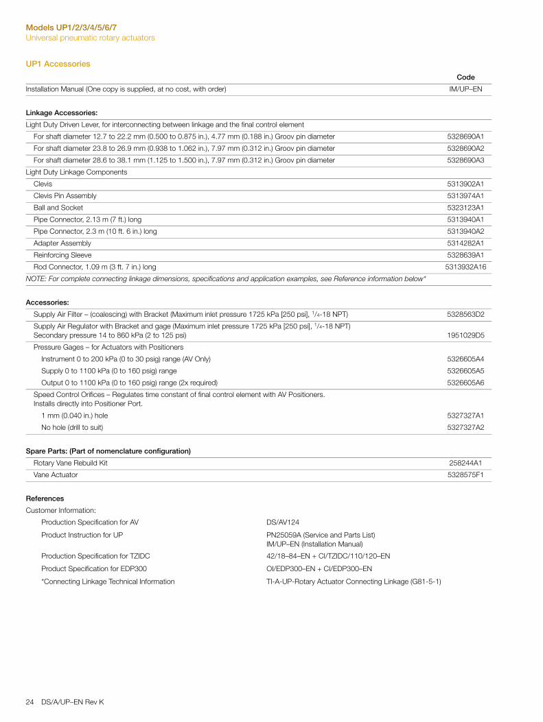
Models UP1/2/3/4/5/6/7Universal pneumatic rotary actuators
UP1 Accessories
Code
Installation Manual (One copy is supplied, at no cost, with order) IM/UP–EN
Linkage Accessories:
Light Duty Driven Lever, for interconnecting between linkage and the final control element
For shaft diameter 12.7 to 22.2 mm (0.500 to 0.875 in.), 4.77 mm (0.188 in.) Groov pin diameter 5328690A1
For shaft diameter 23.8 to 26.9 mm (0.938 to 1.062 in.), 7.97 mm (0.312 in.) Groov pin diameter 5328690A2
For shaft diameter 28.6 to 38.1 mm (1.125 to 1.500 in.), 7.97 mm (0.312 in.) Groov pin diameter 5328690A3
Light Duty Linkage Components
Clevis 5313902A1
Clevis Pin Assembly 5313974A1
Ball and Socket 5323123A1
Pipe Connector, 2.13 m (7 ft.) long 5313940A1
Pipe Connector, 2.3 m (10 ft. 6 in.) long 5313940A2
Adapter Assembly 5314282A1
Reinforcing Sleeve 5328639A1
Rod Connector, 1.09 m (3 ft. 7 in.) long 5313932A16
NOTE: For complete connecting linkage dimensions, specifications and application examples, see Reference information below*
Accessories:
Supply Air Filter – (coalescing) with Bracket (Maximum inlet pressure 1725 kPa [250 psi], 1/4-18 NPT) 5328563D2
Supply Air Regulator with Bracket and gage (Maximum inlet pressure 1725 kPa [250 psi], 1/4-18 NPT)Secondary pressure 14 to 860 kPa (2 to 125 psi) 1951029D5
Pressure Gages – for Actuators with Positioners
Instrument 0 to 200 kPa (0 to 30 psig) range (AV Only) 5326605A4
Supply 0 to 1100 kPa (0 to 160 psig) range 5326605A5
Output 0 to 1100 kPa (0 to 160 psig) range (2x required) 5326605A6
Speed Control Orifices – Regulates time constant of final control element with AV Positioners.Installs directly into Positioner Port.
1 mm (0.040 in.) hole 5327327A1
No hole (drill to suit) 5327327A2
Spare Parts: (Part of nomenclature configuration)
Rotary Vane Rebuild Kit 258244A1
Vane Actuator 5328575F1
References
Customer Information:
Production Specification for AV DS/AV124
Product Instruction for UP PN25059A (Service and Parts List)IM/UP–EN (Installation Manual)
Production Specification for TZIDC 42/18–84–EN + CI/TZIDC/110/120–EN
Product Specification for EDP300 OI/EDP300–EN + CI/EDP300–EN
*Connecting Linkage Technical Information TI-A-UP-Rotary Actuator Connecting Linkage (G81-5-1)
24 DS/A/UP–EN Rev K
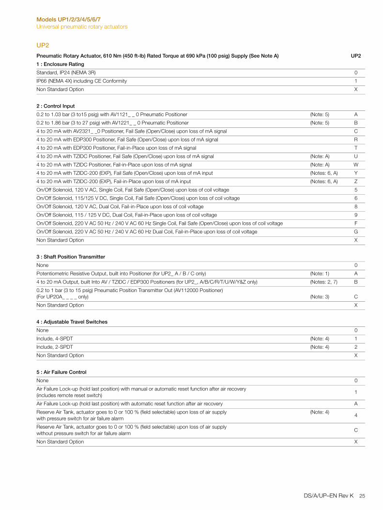
Models UP1/2/3/4/5/6/7Universal pneumatic rotary actuators
UP2
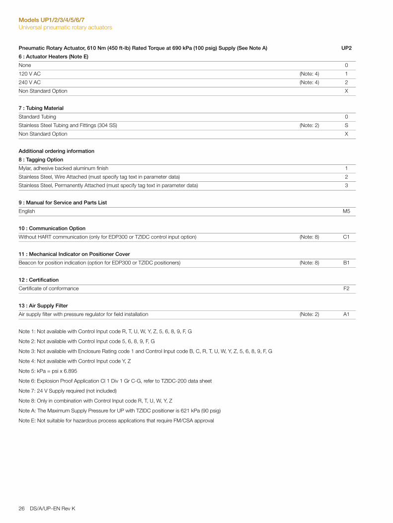
Pneumatic Rotary Actuator, 610 Nm (450 ft-lb) Rated Torque at 690 kPa (100 psig) Supply (See Note A) UP2
1 : Enclosure Rating
Standard, IP24 (NEMA 3R) 0
IP66 (NEMA 4X) including CE Conformity 1
Non Standard Option X
2 : Control Input
0.2 to 1.03 bar (3 to15 psig) with AV1121_ _ 0 Pneumatic Positioner (Note: 5) A
0.2 to 1.86 bar (3 to 27 psig) with AV1221_ _ 0 Pneumatic Positioner (Note: 5) B
4 to 20 mA with AV2321_ _0 Positioner, Fail Safe (Open/Close) upon loss of mA signal C
4 to 20 mA with EDP300 Positioner, Fail Safe (Open/Close) upon loss of mA signal R
4 to 20 mA with EDP300 Positioner, Fail-in-Place upon loss of mA signal T
4 to 20 mA with TZIDC Positioner, Fail Safe (Open/Close) upon loss of mA signal (Note: A) U
4 to 20 mA with TZIDC Positioner, Fail-in-Place upon loss of mA signal (Note: A) W
4 to 20 mA with TZIDC-200 (EXP), Fail Safe (Open/Close) upon loss of mA input (Notes: 6, A) Y
4 to 20 mA with TZIDC-200 (EXP), Fail-in-Place upon loss of mA input (Notes: 6, A) Z
On/Off Solenoid, 120 V AC, Single Coil, Fail Safe (Open/Close) upon loss of coil voltage 5
On/Off Solenoid, 115/125 V DC, Single Coil, Fail Safe (Open/Close) upon loss of coil voltage 6
On/Off Solenoid, 120 V AC, Dual Coil, Fail-in-Place upon loss of coil voltage 8
On/Off Solenoid, 115 / 125 V DC, Dual Coil, Fail-in-Place upon loss of coil voltage 9
On/Off Solenoid, 220 V AC 50 Hz / 240 V AC 60 Hz Single Coil, Fail Safe (Open/Close) upon loss of coil voltage F
On/Off Solenoid, 220 V AC 50 Hz / 240 V AC 60 Hz Dual Coil, Fail-in-Place upon loss of coil voltage G
Non Standard Option X
3 : Shaft Position Transmitter
None 0
Potentiometric Resistive Output, built into Positioner (for UP2_ A / B / C only) (Note: 1) A
4 to 20 mA Output, built Into AV / TZIDC / EDP300 Positioners (for UP2_, A/B/C/R/T/U/W/Y&Z only) (Notes: 2, 7) B
0.2 to 1 bar (3 to 15 psig) Pneumatic Position Transmitter Out (AV112000 Positioner)(For UP20A_ _ _ _ only) (Note: 3) C
Non Standard Option X
4 : Adjustable Travel Switches
None 0
Include, 4-SPDT (Note: 4) 1
Include, 2-SPDT (Note: 4) 2
Non Standard Option X
5 : Air Failure Control
None 0
Air Failure Lock-up (hold last position) with manual or automatic reset function after air recovery (includes remote reset switch)
1
Air Failure Lock-up (hold last position) with automatic reset function after air recovery A
Reserve Air Tank, actuator goes to 0 or 100 % (field selectable) upon loss of air supply with pressure switch for air failure alarm
(Note: 4)4
Reserve Air Tank, actuator goes to 0 or 100 % (field selectable) upon loss of air supply without pressure switch for air failure alarm
C
Non Standard Option X
DS/A/UP–EN Rev K 25
Models UP1/2/3/4/5/6/7Universal pneumatic rotary actuators
6 : Actuator Heaters (Note E)
None 0
120 V AC (Note: 4) 1
240 V AC (Note: 4) 2
Non Standard Option X
7 : Tubing Material
Standard Tubing 0
Stainless Steel Tubing and Fittings (304 SS) (Note: 2) S
Non Standard Option X
Additional ordering information
8 : Tagging Option
Mylar, adhesive backed aluminum finish 1
Stainless Steel, Wire Attached (must specify tag text in parameter data) 2
Stainless Steel, Permanently Attached (must specify tag text in parameter data) 3
9 : Manual for Service and Parts List
English M5
10 : Communication Option
Without HART communication (only for EDP300 or TZIDC control input option) (Note: 8) C1
11 : Mechanical Indicator on Positioner Cover
Beacon for position indication (option for EDP300 or TZIDC positioners) (Note: 8) B1
12 : Certification
Certificate of conformance F2
13 : Air Supply Filter
Air supply filter with pressure regulator for field installation (Note: 2) A1
Note 1: Not available with Control Input code R, T, U, W, Y, Z, 5, 6, 8, 9, F, G
Note 2: Not available with Control Input code 5, 6, 8, 9, F, G
Note 3: Not available with Enclosure Rating code 1 and Control Input code B, C, R, T, U, W, Y, Z, 5, 6, 8, 9, F, G
Note 4: Not available with Control Input code Y, Z
Note 5: kPa = psi x 6.895
Note 6: Explosion Proof Application Cl 1 Div 1 Gr C-G, refer to TZIDC-200 data sheet
Note 7: 24 V Supply required (not included)
Note 8: Only in combination with Control Input code R, T, U, W, Y, Z
Note A: The Maximum Supply Pressure for UP with TZIDC positioner is 621 kPa (90 psig)
Note E: Not suitable for hazardous process applications that require FM/CSA approval
Pneumatic Rotary Actuator, 610 Nm (450 ft-lb) Rated Torque at 690 kPa (100 psig) Supply (See Note A) UP2
26 DS/A/UP–EN Rev K
Models UP1/2/3/4/5/6/7Universal pneumatic rotary actuators
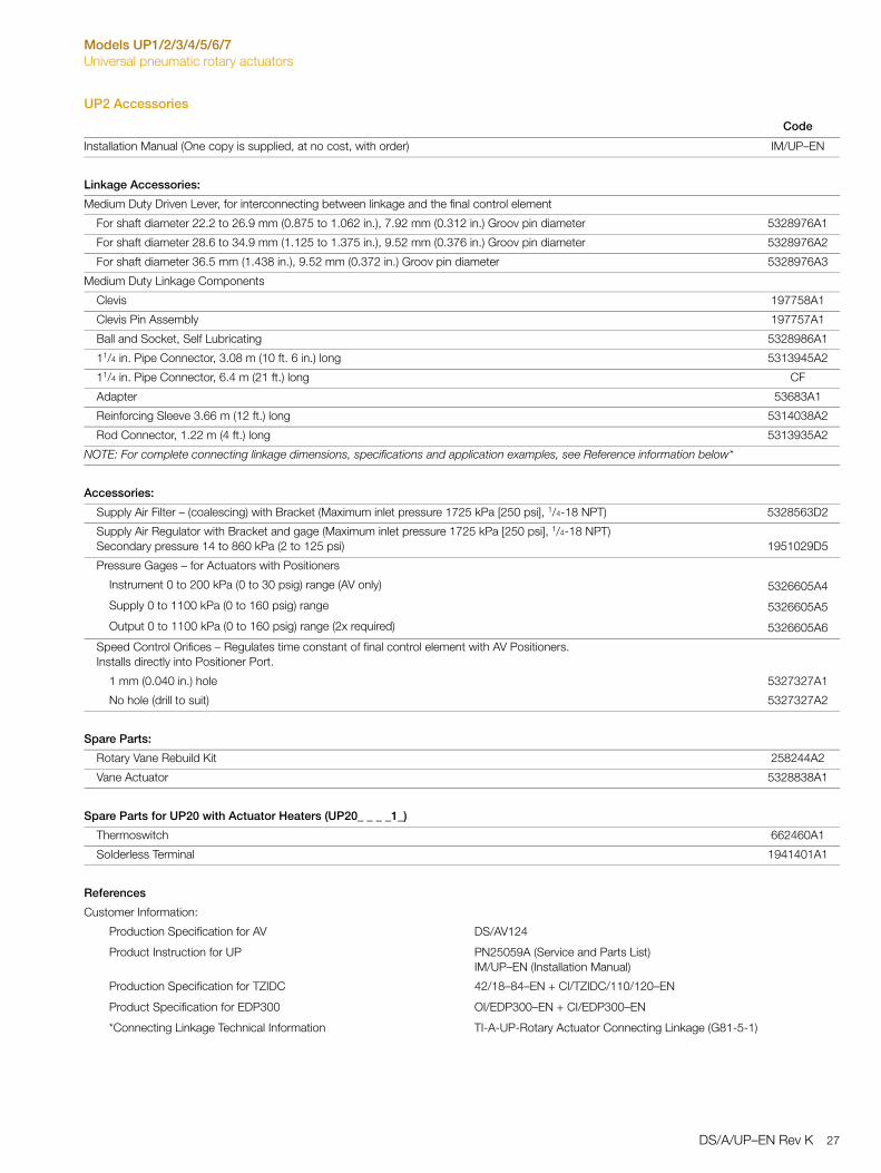
UP2 Accessories
Code
Installation Manual (One copy is supplied, at no cost, with order) IM/UP–EN
Linkage Accessories:
Medium Duty Driven Lever, for interconnecting between linkage and the final control element
For shaft diameter 22.2 to 26.9 mm (0.875 to 1.062 in.), 7.92 mm (0.312 in.) Groov pin diameter 5328976A1
For shaft diameter 28.6 to 34.9 mm (1.125 to 1.375 in.), 9.52 mm (0.376 in.) Groov pin diameter 5328976A2
For shaft diameter 36.5 mm (1.438 in.), 9.52 mm (0.372 in.) Groov pin diameter 5328976A3
Medium Duty Linkage Components
Clevis 197758A1
Clevis Pin Assembly 197757A1
Ball and Socket, Self Lubricating 5328986A1
11/4 in. Pipe Connector, 3.08 m (10 ft. 6 in.) long 5313945A2
11/4 in. Pipe Connector, 6.4 m (21 ft.) long CF
Adapter 53683A1
Reinforcing Sleeve 3.66 m (12 ft.) long 5314038A2
Rod Connector, 1.22 m (4 ft.) long 5313935A2
NOTE: For complete connecting linkage dimensions, specifications and application examples, see Reference information below*
Accessories:
Supply Air Filter – (coalescing) with Bracket (Maximum inlet pressure 1725 kPa [250 psi], 1/4-18 NPT) 5328563D2
Supply Air Regulator with Bracket and gage (Maximum inlet pressure 1725 kPa [250 psi], 1/4-18 NPT)Secondary pressure 14 to 860 kPa (2 to 125 psi) 1951029D5
Pressure Gages – for Actuators with Positioners
Instrument 0 to 200 kPa (0 to 30 psig) range (AV only) 5326605A4
Supply 0 to 1100 kPa (0 to 160 psig) range 5326605A5
Output 0 to 1100 kPa (0 to 160 psig) range (2x required) 5326605A6
Speed Control Orifices – Regulates time constant of final control element with AV Positioners.Installs directly into Positioner Port.
1 mm (0.040 in.) hole 5327327A1
No hole (drill to suit) 5327327A2
Spare Parts:
Rotary Vane Rebuild Kit 258244A2
Vane Actuator 5328838A1
Spare Parts for UP20 with Actuator Heaters (UP20_ _ _ _1_)
Thermoswitch 662460A1
Solderless Terminal 1941401A1
References
Customer Information:
Production Specification for AV DS/AV124
Product Instruction for UP PN25059A (Service and Parts List)IM/UP–EN (Installation Manual)
Production Specification for TZIDC 42/18–84–EN + CI/TZIDC/110/120–EN
Product Specification for EDP300 OI/EDP300–EN + CI/EDP300–EN
*Connecting Linkage Technical Information TI-A-UP-Rotary Actuator Connecting Linkage (G81-5-1)
DS/A/UP–EN Rev K 27

Models UP1/2/3/4/5/6/7Universal pneumatic rotary actuators
UP3
Pneumatic Rotary Actuator, 1085 Nm (800 ft-lb) Rated Torque at 690 kPa (100 psig) Supply (See Note A) UP3
1 : Enclosure Rating
Standard, IP24 (NEMA 3R) 0
IP66 (NEMA 4X) including CE Conformity 1
Non Standard Option X
2 : Control Input
0.2 to 1.03 bar (3 to15 psig) with AV1121_ _ 0 Pneumatic Positioner (Note: 5) A
0.2 to 1.86 bar (3 to 27 psig) with AV1221_ _ 0 Pneumatic Positioner (Note: 5) B
4 to 20 mA with AV2321_ _0 Positioner, Fail Safe (Open/Close) upon loss of mA signal C
4 to 20 mA with EDP300 Positioner, Fail Safe (Open/Close) upon loss of mA signal R
4 to 20 mA with EDP300 Positioner, Fail-in-Place upon loss of mA signal T
4 to 20 mA with TZIDC Positioner, Fail Safe (Open/Close) upon loss of mA signal (Note: A) U
4 to 20 mA with TZIDC Positioner, Fail-in-Place upon loss of mA signal (Note: A) W
4 to 20 mA with TZIDC-200 (EXP), Fail Safe (Open/Close) upon loss of mA input (Notes: 6, A) Y
4 to 20 mA with TZIDC-200 (EXP), Fail-in-Place upon loss of mA input (Notes: 6, A) Z
On/Off Solenoid, 120 V AC, Single Coil, Fail Safe (Open/Close) upon loss of coil voltage 5
On/Off Solenoid, 115/125 V DC, Single Coil, Fail Safe (Open/Close) upon loss of coil voltage 6
On/Off Solenoid, 120 V AC, Dual Coil, Fail-in-Place upon loss of coil voltage 8
On/Off Solenoid, 115 / 125 V DC, Dual Coil, Fail-in-Place upon loss of coil voltage 9
On/Off Solenoid, 220 V AC 50 Hz / 240 V AC 60 Hz Single Coil, Fail Safe (Open/Close) upon loss of coil voltage F
On/Off Solenoid, 220 V AC 50 Hz / 240 V AC 60 Hz Dual Coil, Fail-in-Place upon loss of coil voltage G
Non Standard Option X
3 : Shaft Position Transmitter
None 0
Potentiometric Resistive Output, built into Positioner (for UP3_ A / B / C only) (Note: 1) A
4 to 20 mA Output, built into AV / TZIDC / EDP300 Positioners (for UP3_A/B/C/R/T/U/W/Y&Z only) (Notes: 2, 7) B
0.2 to 1 bar (3 to 15 psig) Pneumatic Position Transmitter (AV112000)(for UP30A_ _ _ _only) (Note: 3) C
Non Standard Option X
4 : Adjustable Travel Switches
None 0
Include, 4-SPDT (Note: 4) 1
Include, 2-SPDT (Note: 4) 2
Non Standard Option X
5 : Air Failure Control
None 0
Air Failure Lock-up (hold last position) with manual or automatic reset function after air recovery (includes remote reset switch and pressure switch)
(Note: 4)1
Air Failure Lock-up (hold last position) with automatic reset function after air recovery without pressure switch for air failure alarm
A
Reserve Air Tank, actuator goes to 0 or 100 % (field selectable) upon loss of air supply with pressure switch for air failure alarm
(Note: 4)4
Reserve Air Tank, actuator goes to 0 or 100 % (field selectable) upon loss of air supply without pressure switch for air failure alarm
C
Non Standard Option X
28 DS/A/UP–EN Rev K

Models UP1/2/3/4/5/6/7Universal pneumatic rotary actuators
6 : Actuator Heaters (Note E)
None 0
120 V AC (Note: 4) 1
240 V AC (Note: 4) 2
Non Standard Option X
7 : Tubing Material
Standard Tubing 0
Stainless Steel Tubing and Fittings (304 SS) (Note: 2) S
Non Standard Option X
Additional ordering information
8 : Tagging Option
Mylar, adhesive backed aluminum finish 1
Stainless Steel, Wire Attached (must specify tag text in parameter data) 2
Stainless Steel, Permanently Attached (must specify tag text in parameter data) 3
9 : Manual for Service and Parts List
English M5
10 : Communication Option
Without HART communication (only for EDP300 or TZIDC control input option) (Note: 8) C1
11 : Mechanical Indicator on Positioner Cover
Beacon for position indication (option for EDP300 or TZIDC positioners) (Note: 8) B1
12 : Certification
Certificate of conformance F2
13 : Air Supply Filter
Air supply filter with pressure regulator for field installation (Note: 2) A1
Note 1: Not available with Control Input code R, T, U, W, Y, Z, 5, 6, 8, 9, F, G
Note 2: Not available with Control Input code 5, 6, 8, 9, F, G
Note 3: Not available with Control Input code B, C, R, T, U, W, Y, Z, 5, 6, 8, 9, F, G
Note 4: Not available with Control Input code Y, Z
Note 5: kPa = psi x 6.895
Note 6: Explosion Proof Application Cl 1 Div 1 Gr C-G, refer to TZIDC-200 data sheet
Note 7: 24 V Supply required (not included)
Note 8: Only in combination with Control Input code R, T, U, W, Y, Z
Note A: The Maximum Supply Pressure for UP with TZIDC positioner is 621 kPa (90 psig)
Note E: Not suitable for hazardous process applications that require FM/CSA approval
Pneumatic Rotary Actuator, 1085 Nm (800 ft-lb) Rated Torque at 690 kPa (100 psig) Supply (See Note A) UP3
DS/A/UP–EN Rev K 29
Models UP1/2/3/4/5/6/7Universal pneumatic rotary actuators
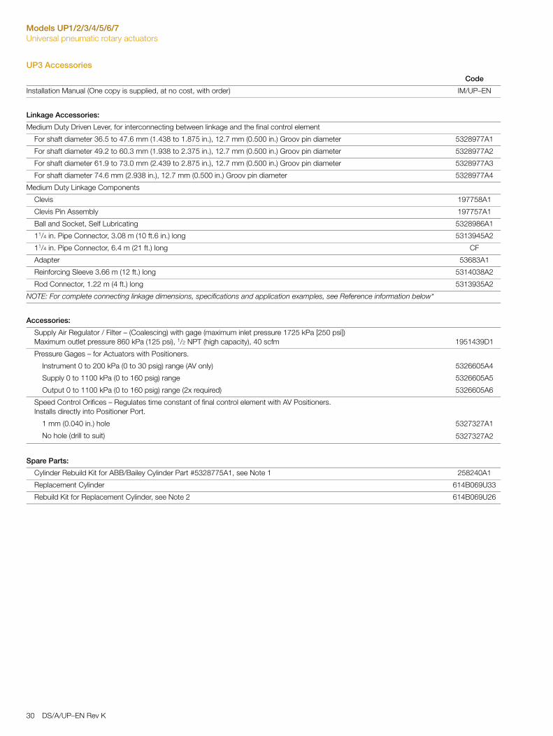
UP3 Accessories
Code
Installation Manual (One copy is supplied, at no cost, with order) IM/UP–EN
Linkage Accessories:
Medium Duty Driven Lever, for interconnecting between linkage and the final control element
For shaft diameter 36.5 to 47.6 mm (1.438 to 1.875 in.), 12.7 mm (0.500 in.) Groov pin diameter 5328977A1
For shaft diameter 49.2 to 60.3 mm (1.938 to 2.375 in.), 12.7 mm (0.500 in.) Groov pin diameter 5328977A2
For shaft diameter 61.9 to 73.0 mm (2.439 to 2.875 in.), 12.7 mm (0.500 in.) Groov pin diameter 5328977A3
For shaft diameter 74.6 mm (2.938 in.), 12.7 mm (0.500 in.) Groov pin diameter 5328977A4
Medium Duty Linkage Components
Clevis 197758A1
Clevis Pin Assembly 197757A1
Ball and Socket, Self Lubricating 5328986A1
11/4 in. Pipe Connector, 3.08 m (10 ft.6 in.) long 5313945A2
11/4 in. Pipe Connector, 6.4 m (21 ft.) long CF
Adapter 53683A1
Reinforcing Sleeve 3.66 m (12 ft.) long 5314038A2
Rod Connector, 1.22 m (4 ft.) long 5313935A2
NOTE: For complete connecting linkage dimensions, specifications and application examples, see Reference information below*
Accessories:
Supply Air Regulator / Filter – (Coalescing) with gage (maximum inlet pressure 1725 kPa [250 psi])Maximum outlet pressure 860 kPa (125 psi), 1/2 NPT (high capacity), 40 scfm 1951439D1
Pressure Gages – for Actuators with Positioners.
Instrument 0 to 200 kPa (0 to 30 psig) range (AV only) 5326605A4
Supply 0 to 1100 kPa (0 to 160 psig) range 5326605A5
Output 0 to 1100 kPa (0 to 160 psig) range (2x required) 5326605A6
Speed Control Orifices – Regulates time constant of final control element with AV Positioners.Installs directly into Positioner Port.
1 mm (0.040 in.) hole 5327327A1
No hole (drill to suit) 5327327A2
Spare Parts:
Cylinder Rebuild Kit for ABB/Bailey Cylinder Part #5328775A1, see Note 1 258240A1
Replacement Cylinder 614B069U33
Rebuild Kit for Replacement Cylinder, see Note 2 614B069U26
30 DS/A/UP–EN Rev K
Models UP1/2/3/4/5/6/7Universal pneumatic rotary actuators
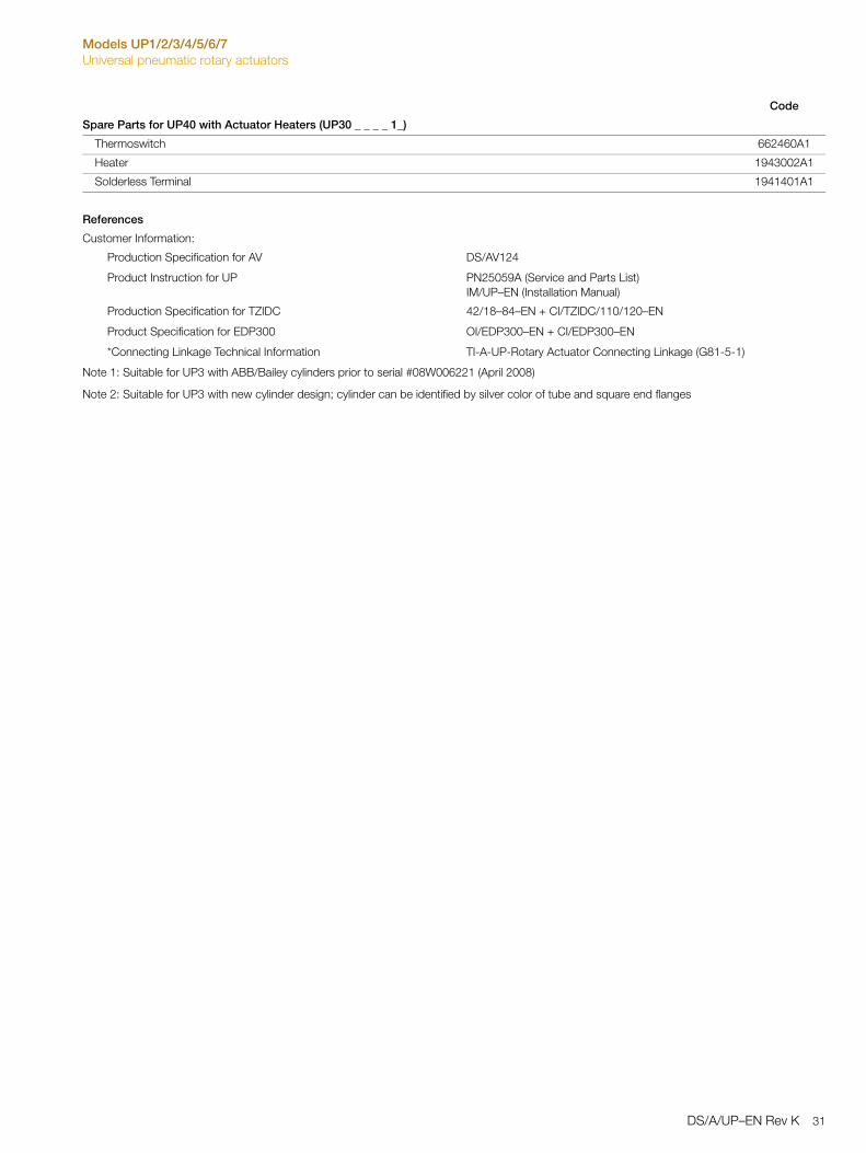
Spare Parts for UP40 with Actuator Heaters (UP30 _ _ _ _ 1_)
Thermoswitch 662460A1
Heater 1943002A1
Solderless Terminal 1941401A1
References
Customer Information:
Production Specification for AV DS/AV124
Product Instruction for UP PN25059A (Service and Parts List)IM/UP–EN (Installation Manual)
Production Specification for TZIDC 42/18–84–EN + CI/TZIDC/110/120–EN
Product Specification for EDP300 OI/EDP300–EN + CI/EDP300–EN
*Connecting Linkage Technical Information TI-A-UP-Rotary Actuator Connecting Linkage (G81-5-1)
Note 1: Suitable for UP3 with ABB/Bailey cylinders prior to serial #08W006221 (April 2008)
Note 2: Suitable for UP3 with new cylinder design; cylinder can be identified by silver color of tube and square end flanges
Code
DS/A/UP–EN Rev K 31
Models UP1/2/3/4/5/6/7Universal pneumatic rotary actuators
UP4
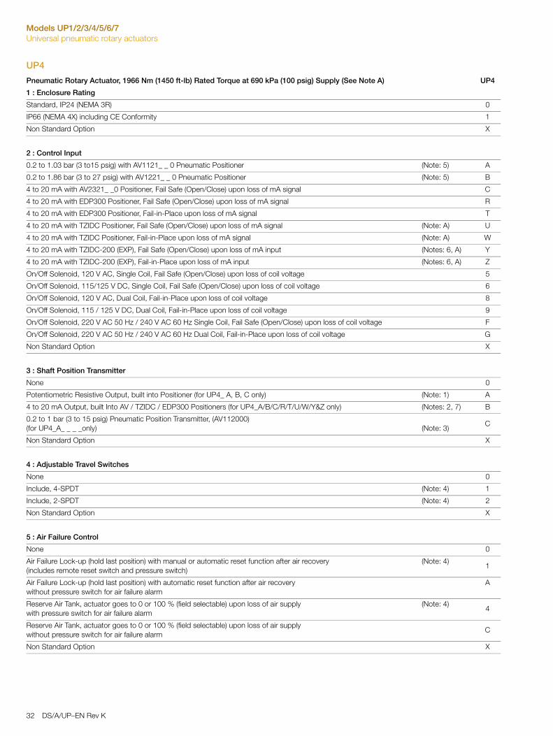
Pneumatic Rotary Actuator, 1966 Nm (1450 ft-lb) Rated Torque at 690 kPa (100 psig) Supply (See Note A) UP4
1 : Enclosure Rating
Standard, IP24 (NEMA 3R) 0
IP66 (NEMA 4X) including CE Conformity 1
Non Standard Option X
2 : Control Input
0.2 to 1.03 bar (3 to15 psig) with AV1121_ _ 0 Pneumatic Positioner (Note: 5) A
0.2 to 1.86 bar (3 to 27 psig) with AV1221_ _ 0 Pneumatic Positioner (Note: 5) B
4 to 20 mA with AV2321_ _0 Positioner, Fail Safe (Open/Close) upon loss of mA signal C
4 to 20 mA with EDP300 Positioner, Fail Safe (Open/Close) upon loss of mA signal R
4 to 20 mA with EDP300 Positioner, Fail-in-Place upon loss of mA signal T
4 to 20 mA with TZIDC Positioner, Fail Safe (Open/Close) upon loss of mA signal (Note: A) U
4 to 20 mA with TZIDC Positioner, Fail-in-Place upon loss of mA signal (Note: A) W
4 to 20 mA with TZIDC-200 (EXP), Fail Safe (Open/Close) upon loss of mA input (Notes: 6, A) Y
4 to 20 mA with TZIDC-200 (EXP), Fail-in-Place upon loss of mA input (Notes: 6, A) Z
On/Off Solenoid, 120 V AC, Single Coil, Fail Safe (Open/Close) upon loss of coil voltage 5
On/Off Solenoid, 115/125 V DC, Single Coil, Fail Safe (Open/Close) upon loss of coil voltage 6
On/Off Solenoid, 120 V AC, Dual Coil, Fail-in-Place upon loss of coil voltage 8
On/Off Solenoid, 115 / 125 V DC, Dual Coil, Fail-in-Place upon loss of coil voltage 9
On/Off Solenoid, 220 V AC 50 Hz / 240 V AC 60 Hz Single Coil, Fail Safe (Open/Close) upon loss of coil voltage F
On/Off Solenoid, 220 V AC 50 Hz / 240 V AC 60 Hz Dual Coil, Fail-in-Place upon loss of coil voltage G
Non Standard Option X
3 : Shaft Position Transmitter
None 0
Potentiometric Resistive Output, built into Positioner (for UP4_ A, B, C only) (Note: 1) A
4 to 20 mA Output, built Into AV / TZIDC / EDP300 Positioners (for UP4_A/B/C/R/T/U/W/Y&Z only) (Notes: 2, 7) B
0.2 to 1 bar (3 to 15 psig) Pneumatic Position Transmitter, (AV112000)(for UP4_A_ _ _ _only) (Note: 3)
C
Non Standard Option X
4 : Adjustable Travel Switches
None 0
Include, 4-SPDT (Note: 4) 1
Include, 2-SPDT (Note: 4) 2
Non Standard Option X
5 : Air Failure Control
None 0
Air Failure Lock-up (hold last position) with manual or automatic reset function after air recovery (includes remote reset switch and pressure switch)
(Note: 4)1
Air Failure Lock-up (hold last position) with automatic reset function after air recovery without pressure switch for air failure alarm
A
Reserve Air Tank, actuator goes to 0 or 100 % (field selectable) upon loss of air supply with pressure switch for air failure alarm
(Note: 4)4
Reserve Air Tank, actuator goes to 0 or 100 % (field selectable) upon loss of air supply without pressure switch for air failure alarm
C
Non Standard Option X
32 DS/A/UP–EN Rev K
Models UP1/2/3/4/5/6/7Universal pneumatic rotary actuators
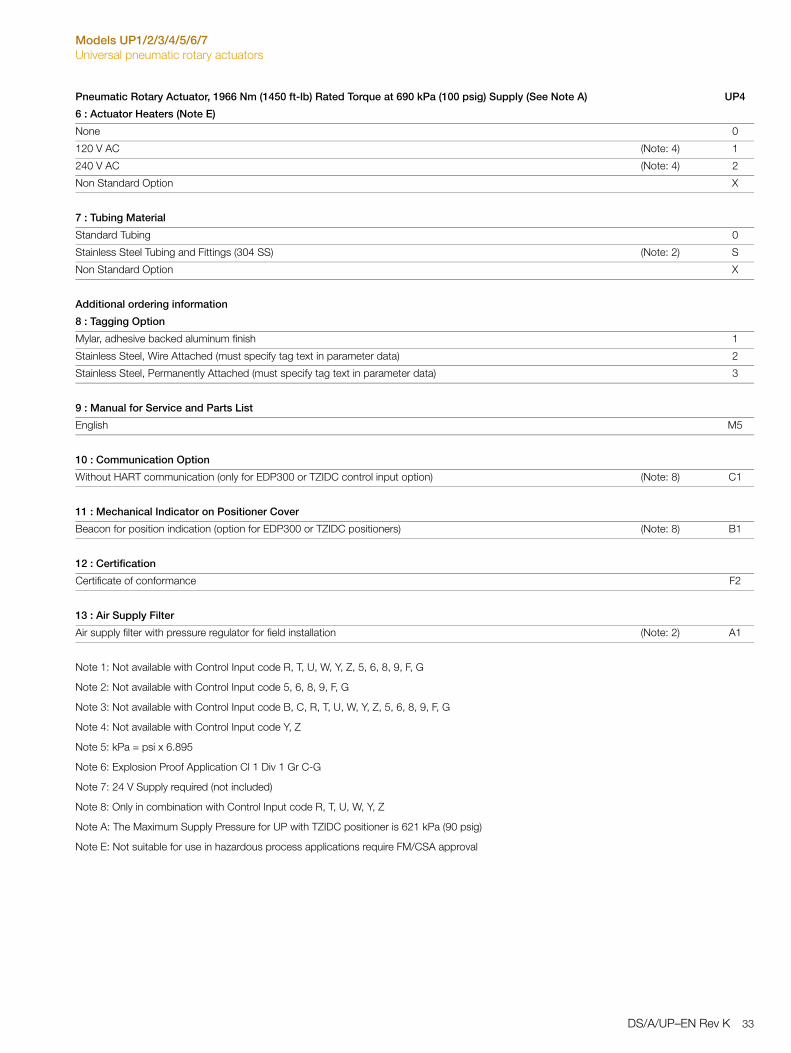
6 : Actuator Heaters (Note E)
None 0
120 V AC (Note: 4) 1
240 V AC (Note: 4) 2
Non Standard Option X
7 : Tubing Material
Standard Tubing 0
Stainless Steel Tubing and Fittings (304 SS) (Note: 2) S
Non Standard Option X
Additional ordering information
8 : Tagging Option
Mylar, adhesive backed aluminum finish 1
Stainless Steel, Wire Attached (must specify tag text in parameter data) 2
Stainless Steel, Permanently Attached (must specify tag text in parameter data) 3
9 : Manual for Service and Parts List
English M5
10 : Communication Option
Without HART communication (only for EDP300 or TZIDC control input option) (Note: 8) C1
11 : Mechanical Indicator on Positioner Cover
Beacon for position indication (option for EDP300 or TZIDC positioners) (Note: 8) B1
12 : Certification
Certificate of conformance F2
13 : Air Supply Filter
Air supply filter with pressure regulator for field installation (Note: 2) A1
Note 1: Not available with Control Input code R, T, U, W, Y, Z, 5, 6, 8, 9, F, G
Note 2: Not available with Control Input code 5, 6, 8, 9, F, G
Note 3: Not available with Control Input code B, C, R, T, U, W, Y, Z, 5, 6, 8, 9, F, G
Note 4: Not available with Control Input code Y, Z
Note 5: kPa = psi x 6.895
Note 6: Explosion Proof Application Cl 1 Div 1 Gr C-G
Note 7: 24 V Supply required (not included)
Note 8: Only in combination with Control Input code R, T, U, W, Y, Z
Note A: The Maximum Supply Pressure for UP with TZIDC positioner is 621 kPa (90 psig)
Note E: Not suitable for use in hazardous process applications require FM/CSA approval
Pneumatic Rotary Actuator, 1966 Nm (1450 ft-lb) Rated Torque at 690 kPa (100 psig) Supply (See Note A) UP4
DS/A/UP–EN Rev K 33
Models UP1/2/3/4/5/6/7Universal pneumatic rotary actuators
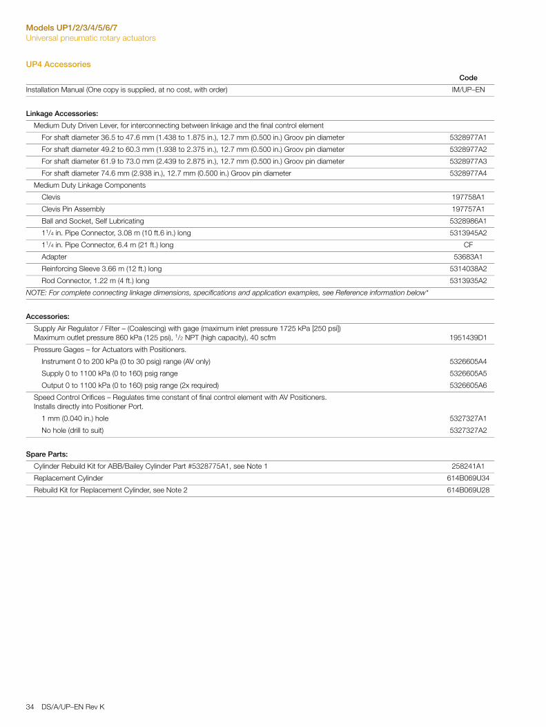
UP4 Accessories
Code
Installation Manual (One copy is supplied, at no cost, with order) IM/UP–EN
Linkage Accessories:
Medium Duty Driven Lever, for interconnecting between linkage and the final control element
For shaft diameter 36.5 to 47.6 mm (1.438 to 1.875 in.), 12.7 mm (0.500 in.) Groov pin diameter 5328977A1
For shaft diameter 49.2 to 60.3 mm (1.938 to 2.375 in.), 12.7 mm (0.500 in.) Groov pin diameter 5328977A2
For shaft diameter 61.9 to 73.0 mm (2.439 to 2.875 in.), 12.7 mm (0.500 in.) Groov pin diameter 5328977A3
For shaft diameter 74.6 mm (2.938 in.), 12.7 mm (0.500 in.) Groov pin diameter 5328977A4
Medium Duty Linkage Components
Clevis 197758A1
Clevis Pin Assembly 197757A1
Ball and Socket, Self Lubricating 5328986A1
11/4 in. Pipe Connector, 3.08 m (10 ft.6 in.) long 5313945A2
11/4 in. Pipe Connector, 6.4 m (21 ft.) long CF
Adapter 53683A1
Reinforcing Sleeve 3.66 m (12 ft.) long 5314038A2
Rod Connector, 1.22 m (4 ft.) long 5313935A2
NOTE: For complete connecting linkage dimensions, specifications and application examples, see Reference information below*
Accessories:
Supply Air Regulator / Filter – (Coalescing) with gage (maximum inlet pressure 1725 kPa [250 psi])Maximum outlet pressure 860 kPa (125 psi), 1/2 NPT (high capacity), 40 scfm 1951439D1
Pressure Gages – for Actuators with Positioners.
Instrument 0 to 200 kPa (0 to 30 psig) range (AV only) 5326605A4
Supply 0 to 1100 kPa (0 to 160) psig range 5326605A5
Output 0 to 1100 kPa (0 to 160) psig range (2x required) 5326605A6
Speed Control Orifices – Regulates time constant of final control element with AV Positioners.Installs directly into Positioner Port.
1 mm (0.040 in.) hole 5327327A1
No hole (drill to suit) 5327327A2
Spare Parts:
Cylinder Rebuild Kit for ABB/Bailey Cylinder Part #5328775A1, see Note 1 258241A1
Replacement Cylinder 614B069U34
Rebuild Kit for Replacement Cylinder, see Note 2 614B069U28
34 DS/A/UP–EN Rev K
Models UP1/2/3/4/5/6/7Universal pneumatic rotary actuators
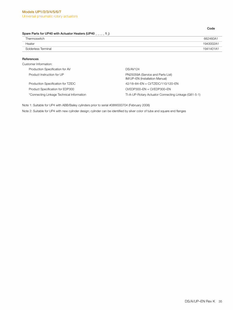
Spare Parts for UP40 with Actuator Heaters (UP40 _ _ _ _ 1_)
Thermoswitch 662460A1
Heater 1943002A1
Solderless Terminal 1941401A1
References
Customer Information:
Production Specification for AV DS/AV124
Product Instruction for UP PN25059A (Service and Parts List)IM/UP–EN (Installation Manual)
Production Specification for TZIDC 42/18–84–EN + CI/TZIDC/110/120–EN
Product Specification for EDP300 OI/EDP300–EN + CI/EDP300–EN
*Connecting Linkage Technical Information TI-A-UP-Rotary Actuator Connecting Linkage (G81-5-1)
Note 1: Suitable for UP4 with ABB/Bailey cylinders prior to serial #08W000704 (February 2008)
Note 2: Suitable for UP4 with new cylinder design; cylinder can be identified by silver color of tube and square end flanges
Code
DS/A/UP–EN Rev K 35
Models UP1/2/3/4/5/6/7Universal pneumatic rotary actuators
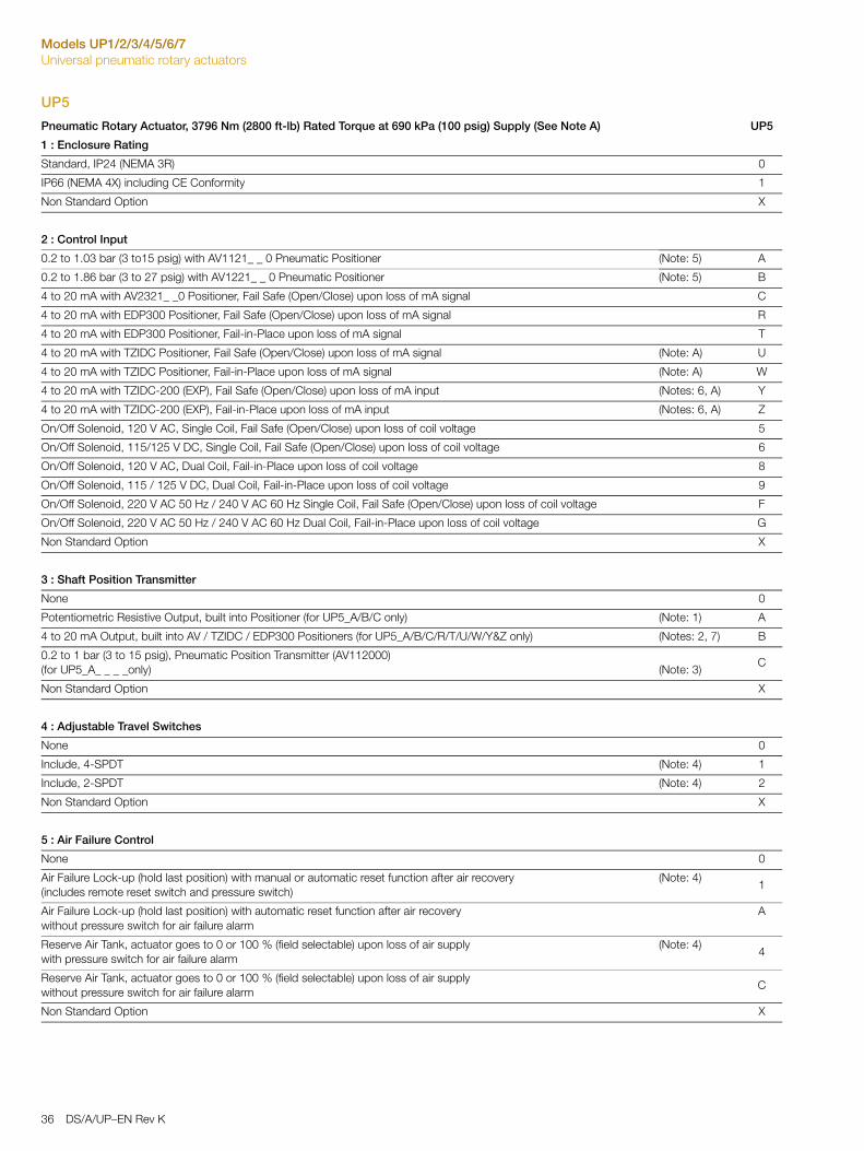
UP5
Pneumatic Rotary Actuator, 3796 Nm (2800 ft-lb) Rated Torque at 690 kPa (100 psig) Supply (See Note A) UP5
1 : Enclosure Rating
Standard, IP24 (NEMA 3R) 0
IP66 (NEMA 4X) including CE Conformity 1
Non Standard Option X
2 : Control Input
0.2 to 1.03 bar (3 to15 psig) with AV1121_ _ 0 Pneumatic Positioner (Note: 5) A
0.2 to 1.86 bar (3 to 27 psig) with AV1221_ _ 0 Pneumatic Positioner (Note: 5) B
4 to 20 mA with AV2321_ _0 Positioner, Fail Safe (Open/Close) upon loss of mA signal C
4 to 20 mA with EDP300 Positioner, Fail Safe (Open/Close) upon loss of mA signal R
4 to 20 mA with EDP300 Positioner, Fail-in-Place upon loss of mA signal T
4 to 20 mA with TZIDC Positioner, Fail Safe (Open/Close) upon loss of mA signal (Note: A) U
4 to 20 mA with TZIDC Positioner, Fail-in-Place upon loss of mA signal (Note: A) W
4 to 20 mA with TZIDC-200 (EXP), Fail Safe (Open/Close) upon loss of mA input (Notes: 6, A) Y
4 to 20 mA with TZIDC-200 (EXP), Fail-in-Place upon loss of mA input (Notes: 6, A) Z
On/Off Solenoid, 120 V AC, Single Coil, Fail Safe (Open/Close) upon loss of coil voltage 5
On/Off Solenoid, 115/125 V DC, Single Coil, Fail Safe (Open/Close) upon loss of coil voltage 6
On/Off Solenoid, 120 V AC, Dual Coil, Fail-in-Place upon loss of coil voltage 8
On/Off Solenoid, 115 / 125 V DC, Dual Coil, Fail-in-Place upon loss of coil voltage 9
On/Off Solenoid, 220 V AC 50 Hz / 240 V AC 60 Hz Single Coil, Fail Safe (Open/Close) upon loss of coil voltage F
On/Off Solenoid, 220 V AC 50 Hz / 240 V AC 60 Hz Dual Coil, Fail-in-Place upon loss of coil voltage G
Non Standard Option X
3 : Shaft Position Transmitter
None 0
Potentiometric Resistive Output, built into Positioner (for UP5_A/B/C only) (Note: 1) A
4 to 20 mA Output, built into AV / TZIDC / EDP300 Positioners (for UP5_A/B/C/R/T/U/W/Y&Z only) (Notes: 2, 7) B
0.2 to 1 bar (3 to 15 psig), Pneumatic Position Transmitter (AV112000)(for UP5_A_ _ _ _only) (Note: 3)
C
Non Standard Option X
4 : Adjustable Travel Switches
None 0
Include, 4-SPDT (Note: 4) 1
Include, 2-SPDT (Note: 4) 2
Non Standard Option X
5 : Air Failure Control
None 0
Air Failure Lock-up (hold last position) with manual or automatic reset function after air recovery (includes remote reset switch and pressure switch)
(Note: 4)1
Air Failure Lock-up (hold last position) with automatic reset function after air recovery without pressure switch for air failure alarm
A
Reserve Air Tank, actuator goes to 0 or 100 % (field selectable) upon loss of air supply with pressure switch for air failure alarm
(Note: 4)4
Reserve Air Tank, actuator goes to 0 or 100 % (field selectable) upon loss of air supply without pressure switch for air failure alarm
C
Non Standard Option X
36 DS/A/UP–EN Rev K
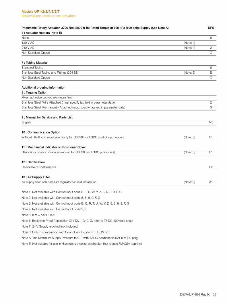
Models UP1/2/3/4/5/6/7Universal pneumatic rotary actuators
6 : Actuator Heaters (Note E)
None 0
120 V AC (Note: 4) 1
240 V AC (Note: 4) 2
Non Standard Option X
7 : Tubing Material
Standard Tubing 0
Stainless Steel Tubing and Fittings (304 SS) (Note: 2) S
Non Standard Option X
Additional ordering information
8 : Tagging Option
Mylar, adhesive backed aluminum finish 1
Stainless Steel, Wire Attached (must specify tag text in parameter data) 2
Stainless Steel, Permanently Attached (must specify tag text in parameter data) 3
9 : Manual for Service and Parts List
English M5
10 : Communication Option
Without HART communication (only for EDP300 or TZIDC control input option) (Note: 8) C1
11 : Mechanical Indicator on Positioner Cover
Beacon for position indication (option for EDP300 or TZIDC positioners) (Note: 8) B1
12 : Certification
Certificate of conformance F2
13 : Air Supply Filter
Air supply filter with pressure regulator for field installation (Note: 2) A1
Note 1: Not available with Control Input code R, T, U, W, Y, Z, 5, 6, 8, 9, F, G
Note 2: Not available with Control Input code 5, 6, 8, 9, F, G
Note 3: Not available with Control Input code B, C, R, T, U, W, Y, Z, 5, 6, 8, 9, F, G
Note 4: Not available with Control Input code Y, Z
Note 5: kPa = psi x 6.895
Note 6: Explosion Proof Application Cl 1 Div 1 Gr C-G, refer to TZIDC-200 data sheet
Note 7: 24 V Supply required (not included)
Note 8: Only in combination with Control Input code R, T, U, W, Y, Z
Note A: The Maximum Supply Pressure for UP with TZIDC positioner is 621 kPa (90 psig)
Note E: Not suitable for use in Hazardous process application that require FM/CSA approval
Pneumatic Rotary Actuator, 3796 Nm (2800 ft-lb) Rated Torque at 690 kPa (100 psig) Supply (See Note A) UP5
DS/A/UP–EN Rev K 37
Models UP1/2/3/4/5/6/7Universal pneumatic rotary actuators
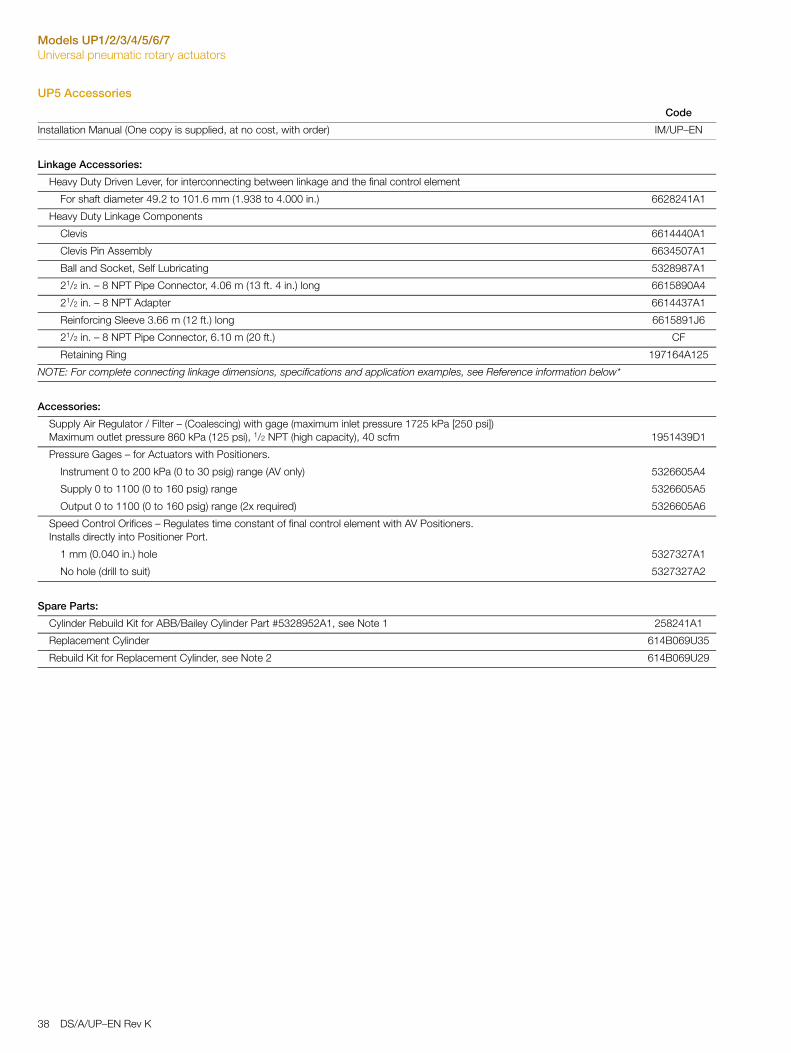
UP5 Accessories
Code
Installation Manual (One copy is supplied, at no cost, with order) IM/UP–EN
Linkage Accessories:
Heavy Duty Driven Lever, for interconnecting between linkage and the final control element
For shaft diameter 49.2 to 101.6 mm (1.938 to 4.000 in.) 6628241A1
Heavy Duty Linkage Components
Clevis 6614440A1
Clevis Pin Assembly 6634507A1
Ball and Socket, Self Lubricating 5328987A1
21/2 in. – 8 NPT Pipe Connector, 4.06 m (13 ft. 4 in.) long 6615890A4
21/2 in. – 8 NPT Adapter 6614437A1
Reinforcing Sleeve 3.66 m (12 ft.) long 6615891J6
21/2 in. – 8 NPT Pipe Connector, 6.10 m (20 ft.) CF
Retaining Ring 197164A125
NOTE: For complete connecting linkage dimensions, specifications and application examples, see Reference information below*
Accessories:
Supply Air Regulator / Filter – (Coalescing) with gage (maximum inlet pressure 1725 kPa [250 psi])Maximum outlet pressure 860 kPa (125 psi), 1/2 NPT (high capacity), 40 scfm 1951439D1
Pressure Gages – for Actuators with Positioners.
Instrument 0 to 200 kPa (0 to 30 psig) range (AV only) 5326605A4
Supply 0 to 1100 (0 to 160 psig) range 5326605A5
Output 0 to 1100 (0 to 160 psig) range (2x required) 5326605A6
Speed Control Orifices – Regulates time constant of final control element with AV Positioners.Installs directly into Positioner Port.
1 mm (0.040 in.) hole 5327327A1
No hole (drill to suit) 5327327A2
Spare Parts:
Cylinder Rebuild Kit for ABB/Bailey Cylinder Part #5328952A1, see Note 1 258241A1
Replacement Cylinder 614B069U35
Rebuild Kit for Replacement Cylinder, see Note 2 614B069U29
38 DS/A/UP–EN Rev K
Models UP1/2/3/4/5/6/7Universal pneumatic rotary actuators
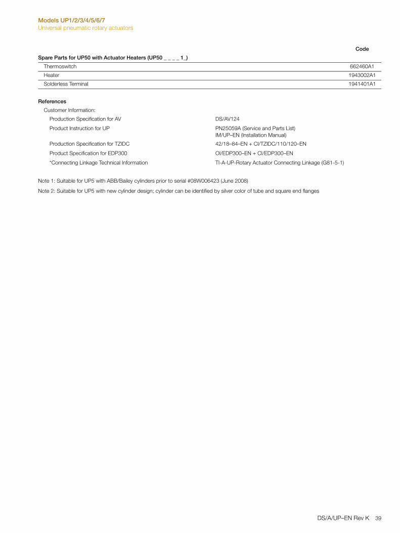
Spare Parts for UP50 with Actuator Heaters (UP50 _ _ _ _ 1_)
Thermoswitch 662460A1
Heater 1943002A1
Solderless Terminal 1941401A1
References
Customer Information:
Production Specification for AV DS/AV124
Product Instruction for UP PN25059A (Service and Parts List)IM/UP–EN (Installation Manual)
Production Specification for TZIDC 42/18–84–EN + CI/TZIDC/110/120–EN
Product Specification for EDP300 OI/EDP300–EN + CI/EDP300–EN
*Connecting Linkage Technical Information TI-A-UP-Rotary Actuator Connecting Linkage (G81-5-1)
Note 1: Suitable for UP5 with ABB/Bailey cylinders prior to serial #08W006423 (June 2008)
Note 2: Suitable for UP5 with new cylinder design; cylinder can be identified by silver color of tube and square end flanges
Code
DS/A/UP–EN Rev K 39
Models UP1/2/3/4/5/6/7Universal pneumatic rotary actuators
UP6
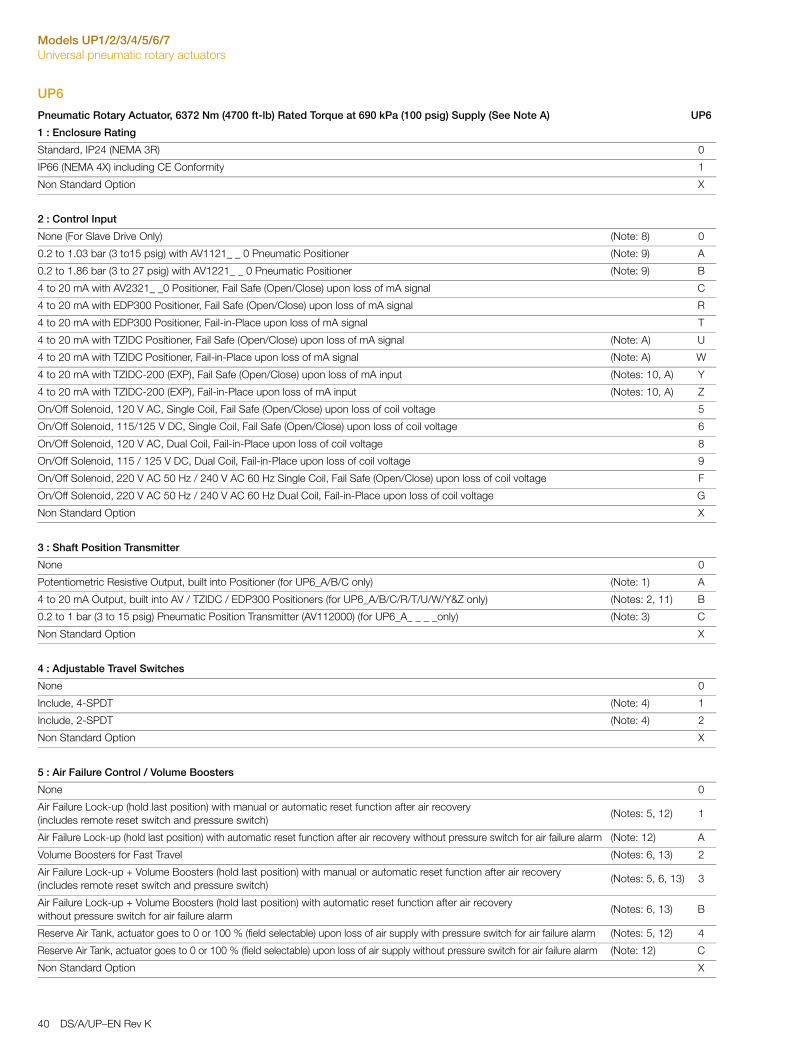
Pneumatic Rotary Actuator, 6372 Nm (4700 ft-lb) Rated Torque at 690 kPa (100 psig) Supply (See Note A) UP6
1 : Enclosure Rating
Standard, IP24 (NEMA 3R) 0
IP66 (NEMA 4X) including CE Conformity 1
Non Standard Option X
2 : Control Input
None (For Slave Drive Only) (Note: 8) 0
0.2 to 1.03 bar (3 to15 psig) with AV1121_ _ 0 Pneumatic Positioner (Note: 9) A
0.2 to 1.86 bar (3 to 27 psig) with AV1221_ _ 0 Pneumatic Positioner (Note: 9) B
4 to 20 mA with AV2321_ _0 Positioner, Fail Safe (Open/Close) upon loss of mA signal C
4 to 20 mA with EDP300 Positioner, Fail Safe (Open/Close) upon loss of mA signal R
4 to 20 mA with EDP300 Positioner, Fail-in-Place upon loss of mA signal T
4 to 20 mA with TZIDC Positioner, Fail Safe (Open/Close) upon loss of mA signal (Note: A) U
4 to 20 mA with TZIDC Positioner, Fail-in-Place upon loss of mA signal (Note: A) W
4 to 20 mA with TZIDC-200 (EXP), Fail Safe (Open/Close) upon loss of mA input (Notes: 10, A) Y
4 to 20 mA with TZIDC-200 (EXP), Fail-in-Place upon loss of mA input (Notes: 10, A) Z
On/Off Solenoid, 120 V AC, Single Coil, Fail Safe (Open/Close) upon loss of coil voltage 5
On/Off Solenoid, 115/125 V DC, Single Coil, Fail Safe (Open/Close) upon loss of coil voltage 6
On/Off Solenoid, 120 V AC, Dual Coil, Fail-in-Place upon loss of coil voltage 8
On/Off Solenoid, 115 / 125 V DC, Dual Coil, Fail-in-Place upon loss of coil voltage 9
On/Off Solenoid, 220 V AC 50 Hz / 240 V AC 60 Hz Single Coil, Fail Safe (Open/Close) upon loss of coil voltage F
On/Off Solenoid, 220 V AC 50 Hz / 240 V AC 60 Hz Dual Coil, Fail-in-Place upon loss of coil voltage G
Non Standard Option X
3 : Shaft Position Transmitter
None 0
Potentiometric Resistive Output, built into Positioner (for UP6_A/B/C only) (Note: 1) A
4 to 20 mA Output, built into AV / TZIDC / EDP300 Positioners (for UP6_A/B/C/R/T/U/W/Y&Z only) (Notes: 2, 11) B
0.2 to 1 bar (3 to 15 psig) Pneumatic Position Transmitter (AV112000) (for UP6_A_ _ _ _only) (Note: 3) C
Non Standard Option X
4 : Adjustable Travel Switches
None 0
Include, 4-SPDT (Note: 4) 1
Include, 2-SPDT (Note: 4) 2
Non Standard Option X
5 : Air Failure Control / Volume Boosters
None 0
Air Failure Lock-up (hold last position) with manual or automatic reset function after air recovery (includes remote reset switch and pressure switch)
(Notes: 5, 12) 1
Air Failure Lock-up (hold last position) with automatic reset function after air recovery without pressure switch for air failure alarm (Note: 12) A
Volume Boosters for Fast Travel (Notes: 6, 13) 2
Air Failure Lock-up + Volume Boosters (hold last position) with manual or automatic reset function after air recovery (includes remote reset switch and pressure switch)
(Notes: 5, 6, 13) 3
Air Failure Lock-up + Volume Boosters (hold last position) with automatic reset function after air recovery without pressure switch for air failure alarm
(Notes: 6, 13) B
Reserve Air Tank, actuator goes to 0 or 100 % (field selectable) upon loss of air supply with pressure switch for air failure alarm (Notes: 5, 12) 4
Reserve Air Tank, actuator goes to 0 or 100 % (field selectable) upon loss of air supply without pressure switch for air failure alarm (Note: 12) C
Non Standard Option X
40 DS/A/UP–EN Rev K

Models UP1/2/3/4/5/6/7Universal pneumatic rotary actuators
6 : Actuator Heaters (Note E)
None 0
120 V AC (Note: 4) 1
240 V AC (Note: 4) 2
Non Standard Option X
7 : Tubing Material
Standard Tubing 0
Stainless Steel Tubing and Fittings (304 SS) (Note: 7) S
Non Standard Option X
Additional ordering information
8 : Tagging Options (Each tag may have 4 lines each consisting of 25 characters)
Mylar, adhesive backed aluminum finish 1
Stainless Steel, Wire Attached (must specify tag text in parameter data) 2
Stainless Steel, Permanently Attached (must specify tag text in parameter data) 3
9 : Manual for Service and Parts List
English M5
10 : Communication Option
Without HART communication (only for EDP300 or TZIDC control input option) (Note: 14) C1
11 : Mechanical Indicator on Positioner Cover
Beacon for position indication (option for EDP300 or TZIDC positioners) (Note: 14) B1
12 : Certification
Certificate of conformance F2
13 : Air Supply Filter
Air supply filter with pressure regulator for field installation (Note: 2) A1
Note 1: Not available with Control Input code R, T, U, W, Y, Z, 5, 6, 8, 9, F, G, 0
Note 2: Not available with Control Input code 5, 6, 8, 9, F, G, 0
Note 3: Not available with Control Input code B, C, R, T, U, W, Y, Z, 5, 6, 8, 9, F, G, 0
Note 4: Not available with Control Input code Y, Z
Note 5: Not available with Control Input code 0, Y, Z
Note 6: Not available with Control Input code 5, 6, 8, 9, F, G, 0, Y, Z
Note 7: Not available with Control Input code 5, 6, 8, 9, F, G
Note 8: Includes Master / Slave Installation Kit, P/N 258458_1
Note 9: kPa = psi x 6.895
Note 10: Explosion Proof Application Cl 1 Div 1 Gr C-G, refer to TZIDC-200 data sheet
Note 11: 24 V Supply required (not included)
Note 12: Not available on UP6_0_ _ _ _ _
Note 13: Not available on UP6_0_ _ _ _ _, Volume Boosters available on UP6_A, B, C, U, W, Y, & Z only
Note 14: Only in combination with Control Input code R, T, U, W, Y, Z
Note A: The Maximum Supply Pressure for UP with TZIDC positioner is 621 kPa (90 psig)
Note E: Not suitable for use in Hazardous process application that require FM/CSA approval
Pneumatic Rotary Actuator, 6372 Nm (4700 ft-lb) Rated Torque at 690 kPa (100 psig) Supply (See Note A) UP6
DS/A/UP–EN Rev K 41
Models UP1/2/3/4/5/6/7Universal pneumatic rotary actuators
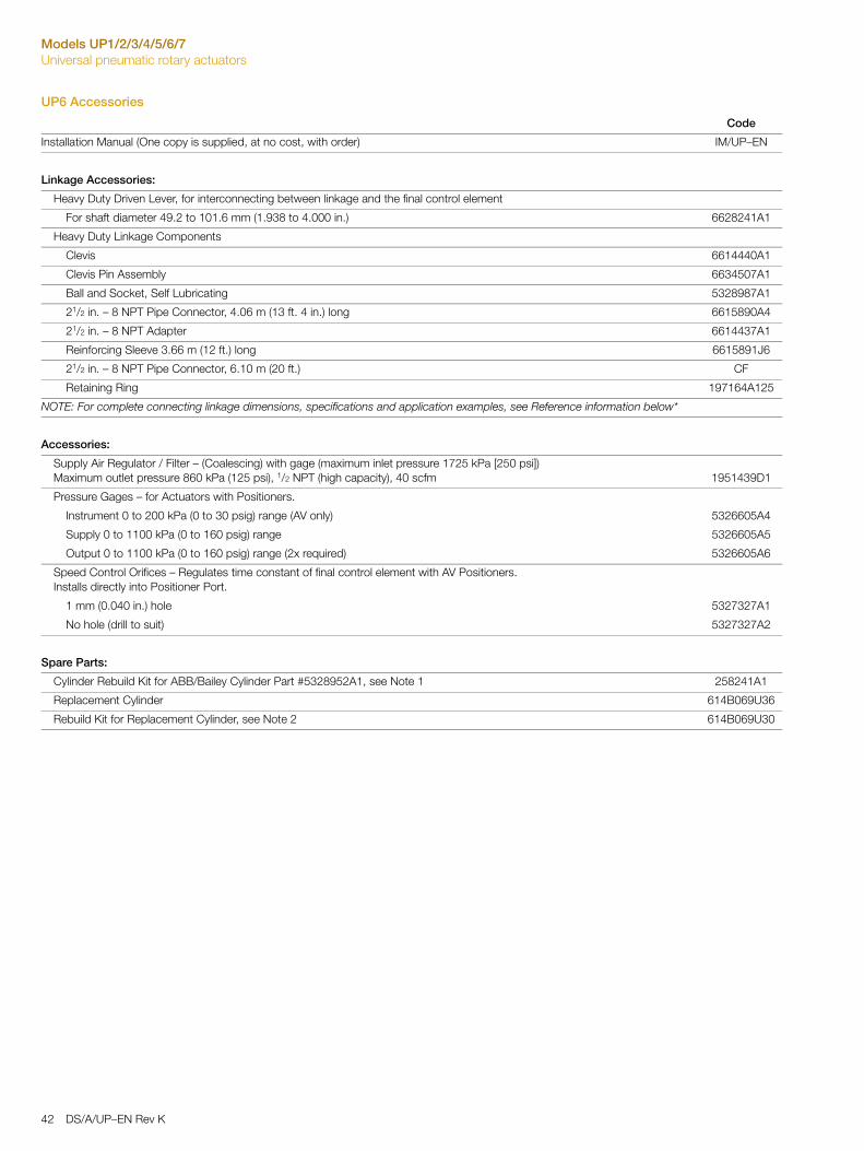
UP6 Accessories
Code
Installation Manual (One copy is supplied, at no cost, with order) IM/UP–EN
Linkage Accessories:
Heavy Duty Driven Lever, for interconnecting between linkage and the final control element
For shaft diameter 49.2 to 101.6 mm (1.938 to 4.000 in.) 6628241A1
Heavy Duty Linkage Components
Clevis 6614440A1
Clevis Pin Assembly 6634507A1
Ball and Socket, Self Lubricating 5328987A1
21/2 in. – 8 NPT Pipe Connector, 4.06 m (13 ft. 4 in.) long 6615890A4
21/2 in. – 8 NPT Adapter 6614437A1
Reinforcing Sleeve 3.66 m (12 ft.) long 6615891J6
21/2 in. – 8 NPT Pipe Connector, 6.10 m (20 ft.) CF
Retaining Ring 197164A125
NOTE: For complete connecting linkage dimensions, specifications and application examples, see Reference information below*
Accessories:
Supply Air Regulator / Filter – (Coalescing) with gage (maximum inlet pressure 1725 kPa [250 psi])Maximum outlet pressure 860 kPa (125 psi), 1/2 NPT (high capacity), 40 scfm 1951439D1
Pressure Gages – for Actuators with Positioners.
Instrument 0 to 200 kPa (0 to 30 psig) range (AV only) 5326605A4
Supply 0 to 1100 kPa (0 to 160 psig) range 5326605A5
Output 0 to 1100 kPa (0 to 160 psig) range (2x required) 5326605A6
Speed Control Orifices – Regulates time constant of final control element with AV Positioners.Installs directly into Positioner Port.
1 mm (0.040 in.) hole 5327327A1
No hole (drill to suit) 5327327A2
Spare Parts:
Cylinder Rebuild Kit for ABB/Bailey Cylinder Part #5328952A1, see Note 1 258241A1
Replacement Cylinder 614B069U36
Rebuild Kit for Replacement Cylinder, see Note 2 614B069U30
42 DS/A/UP–EN Rev K

Models UP1/2/3/4/5/6/7Universal pneumatic rotary actuators
Spare Parts for UP60 with Actuator Heaters (UP60_ _ _ _ 1_)
Thermoswitch 662460A1
Heater 1943002A1
Solderless Terminal 1941401A1
References
Customer Information:
Production Specification for AV DS/AV124
Product Instruction for UP PN25059A (Service and Parts List)IM/UP–EN (Installation Manual)
Production Specification for TZIDC 42/18–84–EN + CI/TZIDC/110/120–EN
Product Specification for EDP300 OI/EDP300–EN + CI/EDP300–EN
*Connecting Linkage Technical Information TI-A-UP-Rotary Actuator Connecting Linkage (G81-5-1)
Note 1: Suitable for UP6; with ABB/Bailey cylinder prior to serial #08W000564 (March 2008)
Note 2: Suitable for UP5 with new cylinder design; cylinder can be identified by silver color of tube and square end flanges
Code
DS/A/UP–EN Rev K 43
Models UP1/2/3/4/5/6/7Universal pneumatic rotary actuators
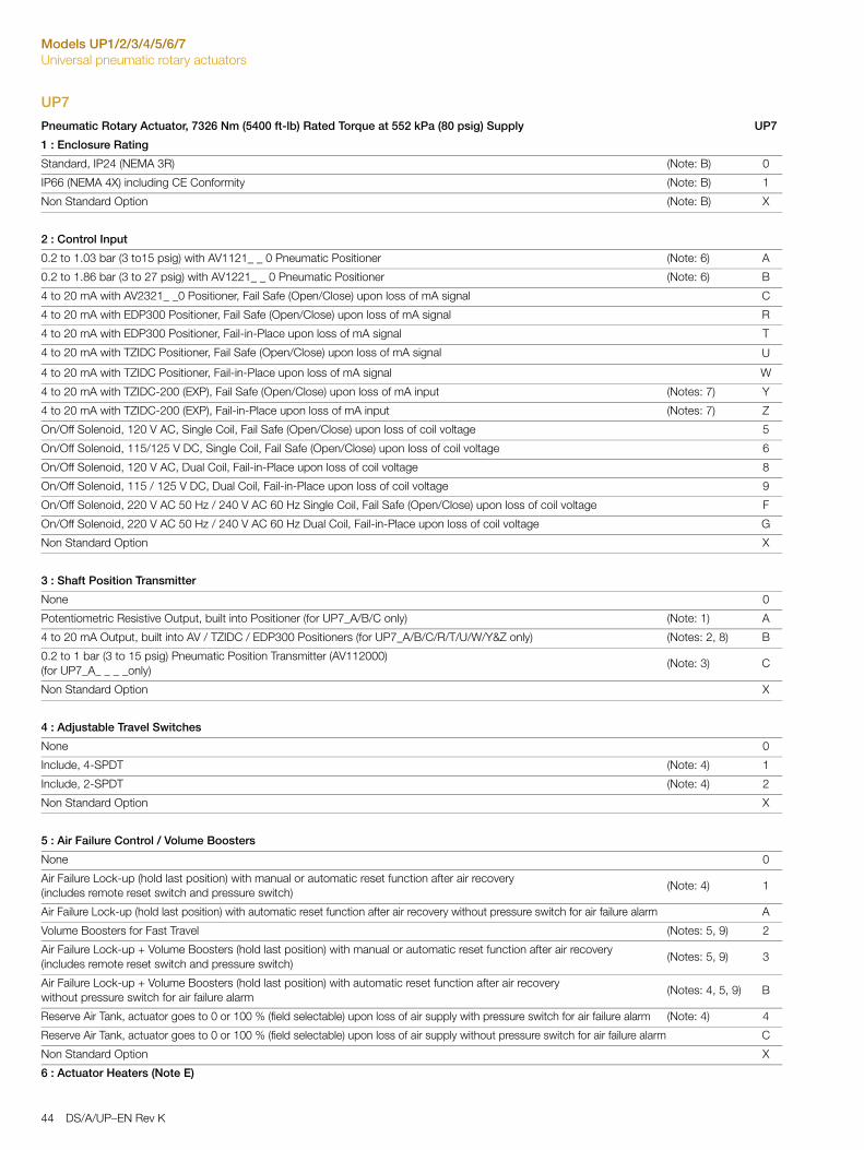
UP7
Pneumatic Rotary Actuator, 7326 Nm (5400 ft-lb) Rated Torque at 552 kPa (80 psig) Supply UP7
1 : Enclosure Rating
Standard, IP24 (NEMA 3R) (Note: B) 0
IP66 (NEMA 4X) including CE Conformity (Note: B) 1
Non Standard Option (Note: B) X
2 : Control Input
0.2 to 1.03 bar (3 to15 psig) with AV1121_ _ 0 Pneumatic Positioner (Note: 6) A
0.2 to 1.86 bar (3 to 27 psig) with AV1221_ _ 0 Pneumatic Positioner (Note: 6) B
4 to 20 mA with AV2321_ _0 Positioner, Fail Safe (Open/Close) upon loss of mA signal C
4 to 20 mA with EDP300 Positioner, Fail Safe (Open/Close) upon loss of mA signal R
4 to 20 mA with EDP300 Positioner, Fail-in-Place upon loss of mA signal T
4 to 20 mA with TZIDC Positioner, Fail Safe (Open/Close) upon loss of mA signal U
4 to 20 mA with TZIDC Positioner, Fail-in-Place upon loss of mA signal W
4 to 20 mA with TZIDC-200 (EXP), Fail Safe (Open/Close) upon loss of mA input (Notes: 7) Y
4 to 20 mA with TZIDC-200 (EXP), Fail-in-Place upon loss of mA input (Notes: 7) Z
On/Off Solenoid, 120 V AC, Single Coil, Fail Safe (Open/Close) upon loss of coil voltage 5
On/Off Solenoid, 115/125 V DC, Single Coil, Fail Safe (Open/Close) upon loss of coil voltage 6
On/Off Solenoid, 120 V AC, Dual Coil, Fail-in-Place upon loss of coil voltage 8
On/Off Solenoid, 115 / 125 V DC, Dual Coil, Fail-in-Place upon loss of coil voltage 9
On/Off Solenoid, 220 V AC 50 Hz / 240 V AC 60 Hz Single Coil, Fail Safe (Open/Close) upon loss of coil voltage F
On/Off Solenoid, 220 V AC 50 Hz / 240 V AC 60 Hz Dual Coil, Fail-in-Place upon loss of coil voltage G
Non Standard Option X
3 : Shaft Position Transmitter
None 0
Potentiometric Resistive Output, built into Positioner (for UP7_A/B/C only) (Note: 1) A
4 to 20 mA Output, built into AV / TZIDC / EDP300 Positioners (for UP7_A/B/C/R/T/U/W/Y&Z only) (Notes: 2, 8) B
0.2 to 1 bar (3 to 15 psig) Pneumatic Position Transmitter (AV112000) (for UP7_A_ _ _ _only)
(Note: 3) C
Non Standard Option X
4 : Adjustable Travel Switches
None 0
Include, 4-SPDT (Note: 4) 1
Include, 2-SPDT (Note: 4) 2
Non Standard Option X
5 : Air Failure Control / Volume Boosters
None 0
Air Failure Lock-up (hold last position) with manual or automatic reset function after air recovery (includes remote reset switch and pressure switch)
(Note: 4) 1
Air Failure Lock-up (hold last position) with automatic reset function after air recovery without pressure switch for air failure alarm A
Volume Boosters for Fast Travel (Notes: 5, 9) 2
Air Failure Lock-up + Volume Boosters (hold last position) with manual or automatic reset function after air recovery(includes remote reset switch and pressure switch)
(Notes: 5, 9) 3
Air Failure Lock-up + Volume Boosters (hold last position) with automatic reset function after air recovery without pressure switch for air failure alarm
(Notes: 4, 5, 9) B
Reserve Air Tank, actuator goes to 0 or 100 % (field selectable) upon loss of air supply with pressure switch for air failure alarm (Note: 4) 4
Reserve Air Tank, actuator goes to 0 or 100 % (field selectable) upon loss of air supply without pressure switch for air failure alarm C
Non Standard Option X
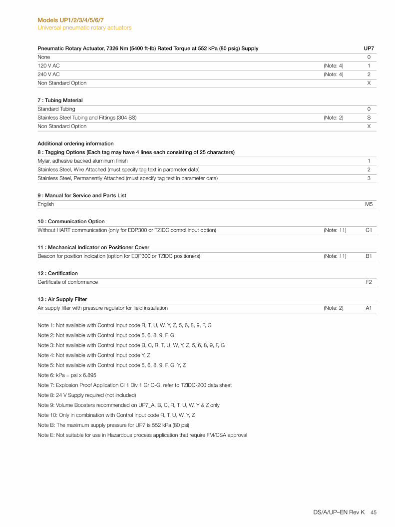
6 : Actuator Heaters (Note E)
44 DS/A/UP–EN Rev K
Models UP1/2/3/4/5/6/7Universal pneumatic rotary actuators
None 0
120 V AC (Note: 4) 1
240 V AC (Note: 4) 2
Non Standard Option X
7 : Tubing Material
Standard Tubing 0
Stainless Steel Tubing and Fittings (304 SS) (Note: 2) S
Non Standard Option X
Additional ordering information
8 : Tagging Options (Each tag may have 4 lines each consisting of 25 characters)
Mylar, adhesive backed aluminum finish 1
Stainless Steel, Wire Attached (must specify tag text in parameter data) 2
Stainless Steel, Permanently Attached (must specify tag text in parameter data) 3
9 : Manual for Service and Parts List
English M5
10 : Communication Option
Without HART communication (only for EDP300 or TZIDC control input option) (Note: 11) C1
11 : Mechanical Indicator on Positioner Cover
Beacon for position indication (option for EDP300 or TZIDC positioners) (Note: 11) B1
12 : Certification
Certificate of conformance F2
13 : Air Supply Filter
Air supply filter with pressure regulator for field installation (Note: 2) A1
Note 1: Not available with Control Input code R, T, U, W, Y, Z, 5, 6, 8, 9, F, G
Note 2: Not available with Control Input code 5, 6, 8, 9, F, G
Note 3: Not available with Control Input code B, C, R, T, U, W, Y, Z, 5, 6, 8, 9, F, G
Note 4: Not available with Control Input code Y, Z
Note 5: Not available with Control Input code 5, 6, 8, 9, F, G, Y, Z
Note 6: kPa = psi x 6.895
Note 7: Explosion Proof Application Cl 1 Div 1 Gr C-G, refer to TZIDC-200 data sheet
Note 8: 24 V Supply required (not included)
Note 9: Volume Boosters recommended on UP7_A, B, C, R, T, U, W, Y & Z only
Note 10: Only in combination with Control Input code R, T, U, W, Y, Z
Note B: The maximum supply pressure for UP7 is 552 kPa (80 psi)
Note E: Not suitable for use in Hazardous process application that require FM/CSA approval
Pneumatic Rotary Actuator, 7326 Nm (5400 ft-lb) Rated Torque at 552 kPa (80 psig) Supply UP7
DS/A/UP–EN Rev K 45
Models UP1/2/3/4/5/6/7Universal pneumatic rotary actuators
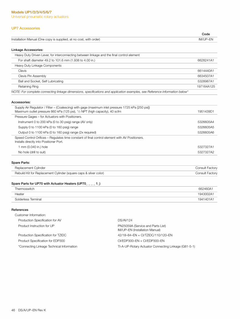
UP7 Accessories
Code
Installation Manual (One copy is supplied, at no cost, with order) IM/UP–EN
Linkage Accessories:
Heavy Duty Driven Lever, for interconnecting between linkage and the final control element
For shaft diameter 49.2 to 101.6 mm (1.938 to 4.00 in.) 6628241A1
Heavy Duty Linkage Components
Clevis 6614440A1
Clevis Pin Assembly 6634507A1
Ball and Socket, Self Lubricating 5328987A1
Retaining Ring 197164A125
NOTE: For complete connecting linkage dimensions, specifications and application examples, see Reference information below*
Accessories:
Supply Air Regulator / Filter – (Coalescing) with gage (maximum inlet pressure 1725 kPa [250 psi])Maximum outlet pressure 860 kPa (125 psi), 1/2 NPT (high capacity), 40 scfm 1951439D1
Pressure Gages – for Actuators with Positioners.
Instrument 0 to 200 kPa (0 to 30 psig) range (AV only) 5326605A4
Supply 0 to 1100 kPa (0 to 160 psig) range 5326605A5
Output 0 to 1100 kPa (0 to 160 psig) range (2x required) 5326605A6
Speed Control Orifices – Regulates time constant of final control element with AV Positioners.Installs directly into Positioner Port.
1 mm (0.040 in.) hole 5327327A1
No hole (drill to suit) 5327327A2
Spare Parts:
Replacement Cylinder Consult Factory
Rebuild Kit for Replacement Cylinder (square caps & silver color) Consult Factory
Spare Parts for UP70 with Actuator Heaters (UP70_ _ _ _ 1_)
Thermoswitch 662460A1
Heater 1943002A1
Solderless Terminal 1941401A1
References
Customer Information:
Production Specification for AV DS/AV124
Product Instruction for UP PN25059A (Service and Parts List)IM/UP–EN (Installation Manual)
Production Specification for TZIDC 42/18–84–EN + CI/TZIDC/110/120–EN
Product Specification for EDP300 OI/EDP300–EN + CI/EDP300–EN
*Connecting Linkage Technical Information TI-A-UP-Rotary Actuator Connecting Linkage (G81-5-1)
46 DS/A/UP–EN Rev K

Models UP1/2/3/4/5/6/7Universal pneumatic rotary actuators
Notes
DS/A/UP–EN Rev K 47
Contact us
DS
/A/U
P–E
N R
ev K
12.2
015
ABB Inc.Process Automation125 E. County Line RoadWarminsterPA 18974USATel: +1 215 674 6000Fax: +1 215 674 7183
ABB Automation Products GmbHProcess AutomationSchillerstr. 7232425MindenGermanyTel: +49 551 905 534Fax: +49 551 905 555
ABB LimitedProcess AutomationSalterbeck Trading EstateWorkingtonCumbria CA14 5DSUKTel: +44 (0)1946 830 611Fax: +44 (0)1946 832 661
www.abb.com
NoteWe reserve the right to make technical changes or modify the contents of this document without prior notice. With regard to purchase orders, the agreed particulars shall prevail. ABB does not accept any responsibility whatsoever for potential errors or possible lack of information in this document.
We reserve all rights in this document and in the subject matter and illustrations contained therein. Any reproduction, disclosure to third parties or utilization of its contents in whole or in parts – is forbidden without prior written consent of ABB.
Copyright© 2015 ABBAll rights reserved
3KXE171201R2001
Sales
Service