universiteit leiden opleiding...
TRANSCRIPT
Universiteit Leiden
Opleiding Informatica
Virtual Machine
for Secure Embedded Systems
Name: Manuel Spierenburg
Date: 05/08/2017
1st supervisor: Dr. ir. Todor Stefanov2nd supervisor: Dr. Teddy Zhai2nd reader: Dr. Kristian Rietveld
MASTER’S THESIS
Leiden Institute of Advanced Computer Science (LIACS)Leiden UniversityNiels Bohrweg 12333 CA LeidenThe Netherlands
Acknowledgments
First of all I want to thank Teddy Zhai who helped and supported my throughout the work of this thesis.Even after he already left the company, where I was working on this project, he guided me and helped meto finish. Without him this would not have been possible.
Also I want to thank Vladimir Zivkovic for giving me this project which gave me the opportunity to finishmy master program. Further I want to thank Irdeto B.V. for giving me the time and equipment, especiallythe access to the ST platform, which allowed me to conduct the experiments for this thesis.
Last but not least I want to thank Todor Stefanov and Kristian Rietveld for giving my advice and fortheir patience.
1
Abstract
In the Broadcasting and Over-The-Top media-service industries, video content which is delivered to thecustomer needs to be secured by encrypting or scrambling the content. The content then needs to bedecrypted or unscrambled at the end-users location. A common technique is to use a hardware devicewhich includes a secret key for the cryptographic operations. Many television providers use a Set-top Box(STB) which is installed at the end-users home to execute this task. The security of the decryption ordescrambling method is enforced in the Set-top box by a Secure Chipset which resides on a System ona Chip (SoC) in the Set-top box. In the market of Digital Video Broadcasting (DVB) or HTTP LiveStreaming (HLS) many different chip vendors compete. The vendors develop their own framework andApplication Programming Interface (API) which have to be used by the Conditional Access System (CAS)and Digital Rights Management (DRM) vendors. The hardware design and implementation decisions are leftwith the Silicon Vendor. This leads to fragmentation and the CAS and DRM vendors need to integrate withmany different solutions. Often broadcasting companies have many different Set-top Boxes with differentChips deployed in the field. Updates for the program which runs on the Secure Chipset therefore have to bedeveloped and tested for the different chip types. This leads to raising costs as, for each chip type, a differentimage has to be produced. Further in the world of Satellite communication it is not possible to unicast animage to a specific STB. All images are broadcast to all the STBs and the STB itself decides which image touse. It is not uncommon that six to ten different images have to be broadcast to all the STBs which leadsto a significant increase of bandwidth. In the case of satellite communication this bandwidth usage is veryexpensive and undesired. In this thesis we propose a solution to decrease this bandwidth by creating anabstraction layer between the Secure Chip and the image running on the chip. We created a Virtual Machine(VM) which can interpret a suitable instruction set. This VM has to be integrated with the different chipvendors only once during production of the chip. The image which runs then on the VM can be deployed inlater stages. The benefit is that only one image has to be produced and broadcast to the STBs which leadsto decrease of the used bandwidth. In this thesis we analyze the code size and performance penalty of theVM compared to a native application running on a secure chip.
Contents
Abbreviations 3
1 Introduction 51.1 Broadcasting Service . . . . . . . . . . . . . . . . . . . . . . . . . . . . . . . . . . . . . . . . . 51.2 Television Encryption . . . . . . . . . . . . . . . . . . . . . . . . . . . . . . . . . . . . . . . . 51.3 Conditional Access Systems . . . . . . . . . . . . . . . . . . . . . . . . . . . . . . . . . . . . . 6
1.3.1 Scrambling . . . . . . . . . . . . . . . . . . . . . . . . . . . . . . . . . . . . . . . . . . 61.3.2 Transmitting Control World . . . . . . . . . . . . . . . . . . . . . . . . . . . . . . . . . 61.3.3 Transmitting Access Information . . . . . . . . . . . . . . . . . . . . . . . . . . . . . . 71.3.4 Protection of ECM and EMM . . . . . . . . . . . . . . . . . . . . . . . . . . . . . . . . 81.3.5 Set-top Box Architecture . . . . . . . . . . . . . . . . . . . . . . . . . . . . . . . . . . 8
1.4 Secure Chip Design . . . . . . . . . . . . . . . . . . . . . . . . . . . . . . . . . . . . . . . . . . 111.5 Problem Description . . . . . . . . . . . . . . . . . . . . . . . . . . . . . . . . . . . . . . . . . 111.6 Solution Approach . . . . . . . . . . . . . . . . . . . . . . . . . . . . . . . . . . . . . . . . . . 111.7 Thesis Contribution . . . . . . . . . . . . . . . . . . . . . . . . . . . . . . . . . . . . . . . . . 121.8 Related Work . . . . . . . . . . . . . . . . . . . . . . . . . . . . . . . . . . . . . . . . . . . . . 12
1.8.1 Self Protecting Digital Content . . . . . . . . . . . . . . . . . . . . . . . . . . . . . . . 121.8.2 Terra Trusted Virtual Machine . . . . . . . . . . . . . . . . . . . . . . . . . . . . . . . 141.8.3 Virtual Machine for Microcontrollers . . . . . . . . . . . . . . . . . . . . . . . . . . . . 141.8.4 Tiny Virtual Machine for Sensor Networks . . . . . . . . . . . . . . . . . . . . . . . . . 151.8.5 ARM TrustZone . . . . . . . . . . . . . . . . . . . . . . . . . . . . . . . . . . . . . . . 16
2 Background 182.1 Virtual Machines . . . . . . . . . . . . . . . . . . . . . . . . . . . . . . . . . . . . . . . . . . . 18
2.1.1 Process And System VMs . . . . . . . . . . . . . . . . . . . . . . . . . . . . . . . . . . 192.2 Instruction Sets . . . . . . . . . . . . . . . . . . . . . . . . . . . . . . . . . . . . . . . . . . . . 20
2.2.1 MIPS Instruction Set . . . . . . . . . . . . . . . . . . . . . . . . . . . . . . . . . . . . 222.2.2 ARM Instruction Set . . . . . . . . . . . . . . . . . . . . . . . . . . . . . . . . . . . . . 25
2.3 Comparison between MIPS and ARM Instruction Sets . . . . . . . . . . . . . . . . . . . . . . 302.4 Security of Embedded Systems . . . . . . . . . . . . . . . . . . . . . . . . . . . . . . . . . . . 30
3 Design and Implementation 353.1 VM Software Design . . . . . . . . . . . . . . . . . . . . . . . . . . . . . . . . . . . . . . . . . 35
3.1.1 VM Data Model . . . . . . . . . . . . . . . . . . . . . . . . . . . . . . . . . . . . . . . 363.1.2 VM Image Loader . . . . . . . . . . . . . . . . . . . . . . . . . . . . . . . . . . . . . . 363.1.3 VM Encoder . . . . . . . . . . . . . . . . . . . . . . . . . . . . . . . . . . . . . . . . . 373.1.4 VM Emulator . . . . . . . . . . . . . . . . . . . . . . . . . . . . . . . . . . . . . . . . . 383.1.5 System Calls . . . . . . . . . . . . . . . . . . . . . . . . . . . . . . . . . . . . . . . . . 38
3.2 Additional Instruction Sets . . . . . . . . . . . . . . . . . . . . . . . . . . . . . . . . . . . . . 393.3 Virtual Machine Runtime . . . . . . . . . . . . . . . . . . . . . . . . . . . . . . . . . . . . . . 39
1
3.3.1 MIPS Virtual Machine Runtime . . . . . . . . . . . . . . . . . . . . . . . . . . . . . . 403.3.2 ARM Virtual Machine Runtime . . . . . . . . . . . . . . . . . . . . . . . . . . . . . . . 42
3.4 Application Image . . . . . . . . . . . . . . . . . . . . . . . . . . . . . . . . . . . . . . . . . . 43
4 Case Studies And Experimental Setup 444.1 Experimental Applications . . . . . . . . . . . . . . . . . . . . . . . . . . . . . . . . . . . . . . 44
4.1.1 Application with Hardware Crypto Module . . . . . . . . . . . . . . . . . . . . . . . . 444.1.2 Application with Software Crypto . . . . . . . . . . . . . . . . . . . . . . . . . . . . . 45
4.2 Experimental Platforms . . . . . . . . . . . . . . . . . . . . . . . . . . . . . . . . . . . . . . . 464.2.1 Arduino Platform . . . . . . . . . . . . . . . . . . . . . . . . . . . . . . . . . . . . . . 464.2.2 ST Platform . . . . . . . . . . . . . . . . . . . . . . . . . . . . . . . . . . . . . . . . . 48
4.3 Create Application Image and Virtual Machine . . . . . . . . . . . . . . . . . . . . . . . . . . 494.3.1 Compile and Link Application Image . . . . . . . . . . . . . . . . . . . . . . . . . . . . 504.3.2 Compile Virtual Machine . . . . . . . . . . . . . . . . . . . . . . . . . . . . . . . . . . 51
5 Experiments and Results 535.1 Code Size Overhead of VM . . . . . . . . . . . . . . . . . . . . . . . . . . . . . . . . . . . . . 53
5.1.1 Application 1 . . . . . . . . . . . . . . . . . . . . . . . . . . . . . . . . . . . . . . . . . 535.1.2 Application 2 . . . . . . . . . . . . . . . . . . . . . . . . . . . . . . . . . . . . . . . . . 55
5.2 Execution Time Slowdown . . . . . . . . . . . . . . . . . . . . . . . . . . . . . . . . . . . . . . 575.2.1 Application 1 . . . . . . . . . . . . . . . . . . . . . . . . . . . . . . . . . . . . . . . . . 575.2.2 Application 2 . . . . . . . . . . . . . . . . . . . . . . . . . . . . . . . . . . . . . . . . . 58
5.3 Executed Instructions Analysis . . . . . . . . . . . . . . . . . . . . . . . . . . . . . . . . . . . 60
6 Conclusion 61
7 Future Work 62
Bibliography 63
A MIPS 1 Instructions 65
B MIPS 1 Encoding 68
C ARMv6 Cortex-M0 Instructions 70
D ARM Encoding 73
2
Abbreviations
ABI Application Binary Interface.
ACPU Application Central Processing Unit.
ALU Arithmetic Logic Unit.
AM amplitude modulation.
API Application Programming Interface.
APRS Applicatoin Program Status Register.
ARM Advanced RISC Machine.
CAS Conditional Access System.
CISC Complex Instruction Set Computing.
CPU Central Processing Unit.
DBS Direct-broadcast Satellite.
DRM Digital Rights Management.
DVB Digital Video Broadcasting.
DVB-CI DVB Common Interface.
ECM Entitled Control Word Message.
EMM Entitled Management Messages.
FM frequency modulation.
HLS HTTP Live Streaming.
ISA Instruction Set Architecture.
OTA Over The Air Broadcasting.
PC Program Counter.
RISC Reduced Instruction Set Computing.
3
SCPU Secure Central Processing Unit.
SoC System on a Chip.
STB Set-top Box.
TA Trusted Application.
TEE Trusted Execution Environment.
TVMM Trusted Virtual Machine Monitor.
VLIW Very Long Instruction Word.
VM Virtual Machine.
VMM Virtual Machine Monitor.
4
Chapter 1
Introduction
In this chapter we provide background information about broadcasting of video content and how it is secured.Further in Section 1.5 we discuss the problem and the research questions. In the following section the solutionapproach is described. In addition we present some related work in the field and compare it to our approachin Section 1.8.
1.1 Broadcasting Service
Broadcasting describes the distribution of media content such as audio or video to customers in a one to manymodel. For the distribution of the content, different communication systems were used over the years. Thefirst broadcast system used radio transmitter and receivers to transmit content via radio signals over the air.This kind of broadcasting is also called Over The Air Broadcasting (OTA) or terrestrial transmission. Thesignal transmitted thereby was an analog signal. In analog broadcasting, all channels are broadcast at thesame time. The receiver then has to filter the signal to enable the end user to consume the desired channel.The separation of the different channels is achieved by modulation, either frequency modulation (FM) oramplitude modulation (AM). For example with frequency modulation, the signal of a channel is encoded intothe radio signal with a dedicated frequency. The receiver then can receive the specific channel by separatingout the signal on the dedicated frequency. Later on cable transmission was introduced which allowed tobroadcast more channels with less interference. Often the cable providers use local satellite stations anddistribute the signal from there over cables to the customers. Another possibility is when the customer hasa satellite receiver and directly connects to the broadcast satellite. This kind of transmission is also calledDirect-broadcast Satellite (DBS). This new broadcasting techniques allowed to enable new business modelswhere the customers pay for subscription. This in return introduced new requirements on the security ofthe broadcast signal. To prevent users without subscription stealing the signal, new security measures hadto be implemented.
1.2 Television Encryption
The access to television services is secured by encrypting the signal. In television this method is oftenalso called “scrambling”. In the beginning television encryption involved filtering out channels to userswithout subscription. With more channels available and more users with subscription, this system becameunmanageable. Newer systems introduced interference signals to channels and users with subscription neededa set-top box to descramble the signal. But these analog encryption systems were all broken. With the riseof digital television more sophisticated encryption mechanisms were introduced.
5
1.3 Conditional Access Systems
Conditional Access System (CAS) describe a whole system which is used in digital television to protectcontent. The system can control subscriber access to services, programmes and events. Generally a CASsystem consist of two subsystems. A scrambling subsystem which scrambles and descrambles the mediacontent for only subscribed users, and an access control system which determines if descrambling of thecontent is allowed. An international standard for conditional access systems (DVB-CA) has been introducedwhich includes a Common Scrambling Algorithm (DVB-CSA) and a Common Interface (DVB-CI) for accesscontrol. The content in the standard is secured with a control word key of 128 bits. The encryption algorithmitself is based on a two block cipher where the first algorithm is a variation of the AES128 cipher called AES’and the second algorithm is a confidential cipher called eXtended emulation Resistant Cipher (XRC). Thecontrol word itself is derived from another key and changes several times per minute.
1.3.1 Scrambling
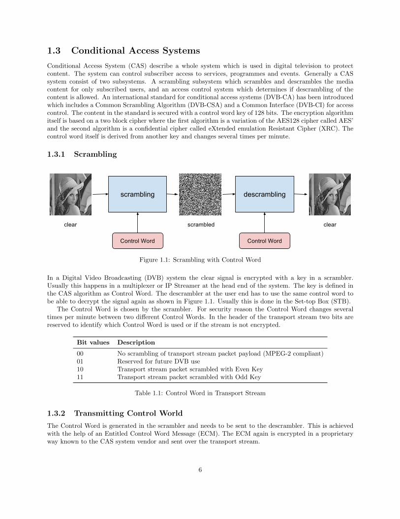
Figure 1.1: Scrambling with Control Word
In a Digital Video Broadcasting (DVB) system the clear signal is encrypted with a key in a scrambler.Usually this happens in a multiplexer or IP Streamer at the head end of the system. The key is defined inthe CAS algorithm as Control Word. The descrambler at the user end has to use the same control word tobe able to decrypt the signal again as shown in Figure 1.1. Usually this is done in the Set-top Box (STB).
The Control Word is chosen by the scrambler. For security reason the Control Word changes severaltimes per minute between two different Control Words. In the header of the transport stream two bits arereserved to identify which Control Word is used or if the stream is not encrypted.
Bit values Description
00 No scrambling of transport stream packet payload (MPEG-2 compliant)01 Reserved for future DVB use10 Transport stream packet scrambled with Even Key11 Transport stream packet scrambled with Odd Key
Table 1.1: Control Word in Transport Stream
1.3.2 Transmitting Control World
The Control Word is generated in the scrambler and needs to be sent to the descrambler. This is achievedwith the help of an Entitled Control Word Message (ECM). The ECM again is encrypted in a proprietaryway known to the CAS system vendor and sent over the transport stream.
6
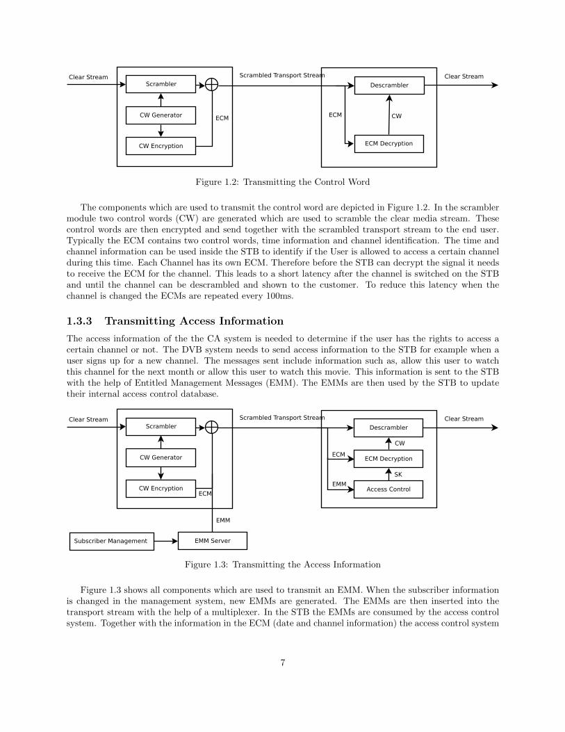
Figure 1.2: Transmitting the Control Word
The components which are used to transmit the control word are depicted in Figure 1.2. In the scramblermodule two control words (CW) are generated which are used to scramble the clear media stream. Thesecontrol words are then encrypted and send together with the scrambled transport stream to the end user.Typically the ECM contains two control words, time information and channel identification. The time andchannel information can be used inside the STB to identify if the User is allowed to access a certain channelduring this time. Each Channel has its own ECM. Therefore before the STB can decrypt the signal it needsto receive the ECM for the channel. This leads to a short latency after the channel is switched on the STBand until the channel can be descrambled and shown to the customer. To reduce this latency when thechannel is changed the ECMs are repeated every 100ms.
1.3.3 Transmitting Access Information
The access information of the the CA system is needed to determine if the user has the rights to access acertain channel or not. The DVB system needs to send access information to the STB for example when auser signs up for a new channel. The messages sent include information such as, allow this user to watchthis channel for the next month or allow this user to watch this movie. This information is sent to the STBwith the help of Entitled Management Messages (EMM). The EMMs are then used by the STB to updatetheir internal access control database.
Figure 1.3: Transmitting the Access Information
Figure 1.3 shows all components which are used to transmit an EMM. When the subscriber informationis changed in the management system, new EMMs are generated. The EMMs are then inserted into thetransport stream with the help of a multiplexer. In the STB the EMMs are consumed by the access controlsystem. Together with the information in the ECM (date and channel information) the access control system
7
decides if the user is allowed to descramble this content. The content of the EMM is proprietary and differsby CAS vendor.
1.3.4 Protection of ECM and EMM
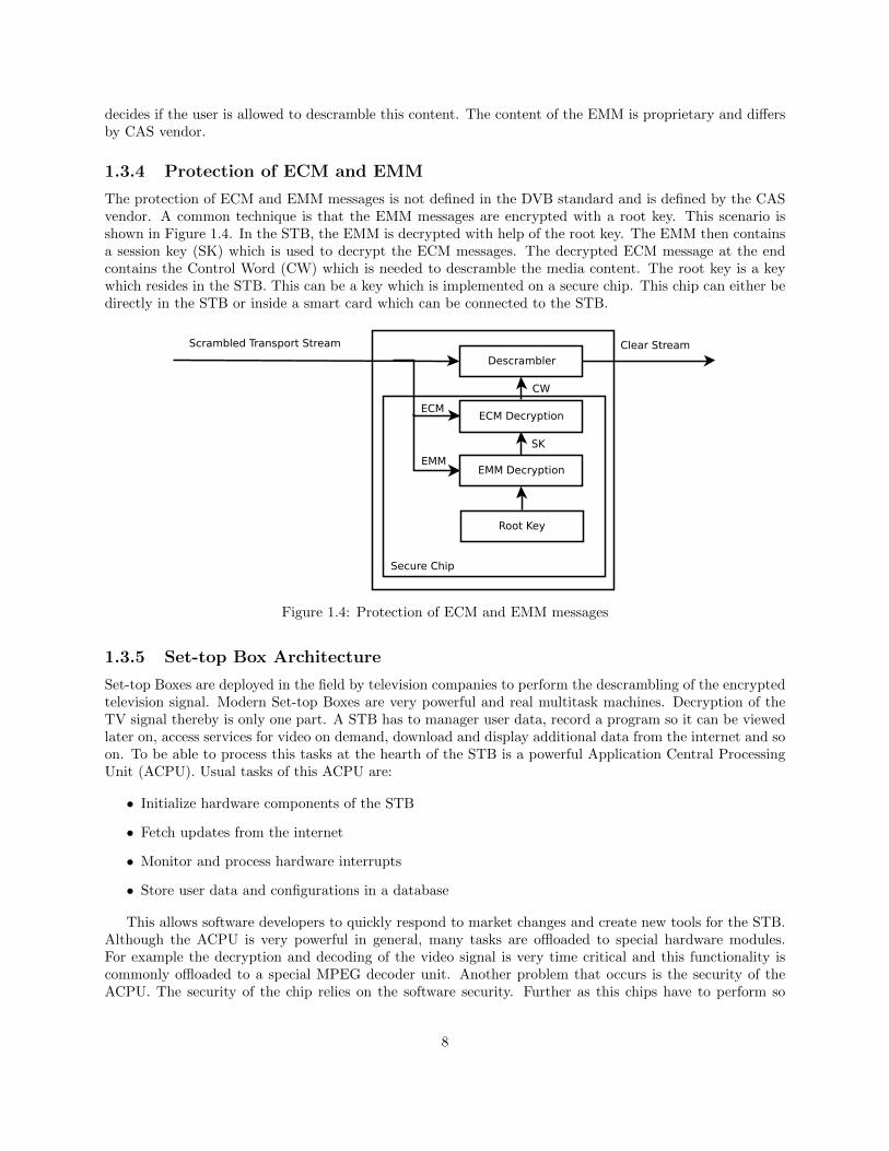
The protection of ECM and EMM messages is not defined in the DVB standard and is defined by the CASvendor. A common technique is that the EMM messages are encrypted with a root key. This scenario isshown in Figure 1.4. In the STB, the EMM is decrypted with help of the root key. The EMM then containsa session key (SK) which is used to decrypt the ECM messages. The decrypted ECM message at the endcontains the Control Word (CW) which is needed to descramble the media content. The root key is a keywhich resides in the STB. This can be a key which is implemented on a secure chip. This chip can either bedirectly in the STB or inside a smart card which can be connected to the STB.
Figure 1.4: Protection of ECM and EMM messages
1.3.5 Set-top Box Architecture
Set-top Boxes are deployed in the field by television companies to perform the descrambling of the encryptedtelevision signal. Modern Set-top Boxes are very powerful and real multitask machines. Decryption of theTV signal thereby is only one part. A STB has to manager user data, record a program so it can be viewedlater on, access services for video on demand, download and display additional data from the internet and soon. To be able to process this tasks at the hearth of the STB is a powerful Application Central ProcessingUnit (ACPU). Usual tasks of this ACPU are:
• Initialize hardware components of the STB
• Fetch updates from the internet
• Monitor and process hardware interrupts
• Store user data and configurations in a database
This allows software developers to quickly respond to market changes and create new tools for the STB.Although the ACPU is very powerful in general, many tasks are offloaded to special hardware modules.For example the decryption and decoding of the video signal is very time critical and this functionality iscommonly offloaded to a special MPEG decoder unit. Another problem that occurs is the security of theACPU. The security of the chip relies on the software security. Further as this chips have to perform so
8

many tasks, they have mostly access to various components such as a database, file system and a networkcard. These factors increase the vulnerability and make these units not suitable for secure implementationof the conditional access system. Therefore, a Secure Central Processing Unit (SCPU) is introduced whichcan be accessed from the ACPU with a defined protocol. The separation of the components is depicted inFigure 1.5. The ACPU is considered to be non secure and has access to all resources. The encoder and theSCPU are segregated from other resources for security reason.
Figure 1.5: Set-top Box Components
In terms of software we can define two main components in a STB, the operating system and theconditional access system. The operating system includes the main system including a kernel which is startupwhen the STB is powered on. This OS manages different resources, interacts with hardware components liketv tuner, displays a graphical user interface and processes commands sent via the remote control. At themoment no standard STB OS exists. Broadcasters and STB manufacturers build their own operating systemwhich are often based on either Linux or Windows. These systems are generally hard to secure and are notsuitable for the conditional access system. The CA system itself resides on the secure chip which providesprotection against attacks and tampering. The DVB Common Interface (DVB-CI) defines the connectionbetween the operating system and the CA system. This standard enables the interoperability of STB modelsbetween different CAS vendors. A television company can choose between different STB models and combineit with the CAS system of choice if they follow the standard.
9
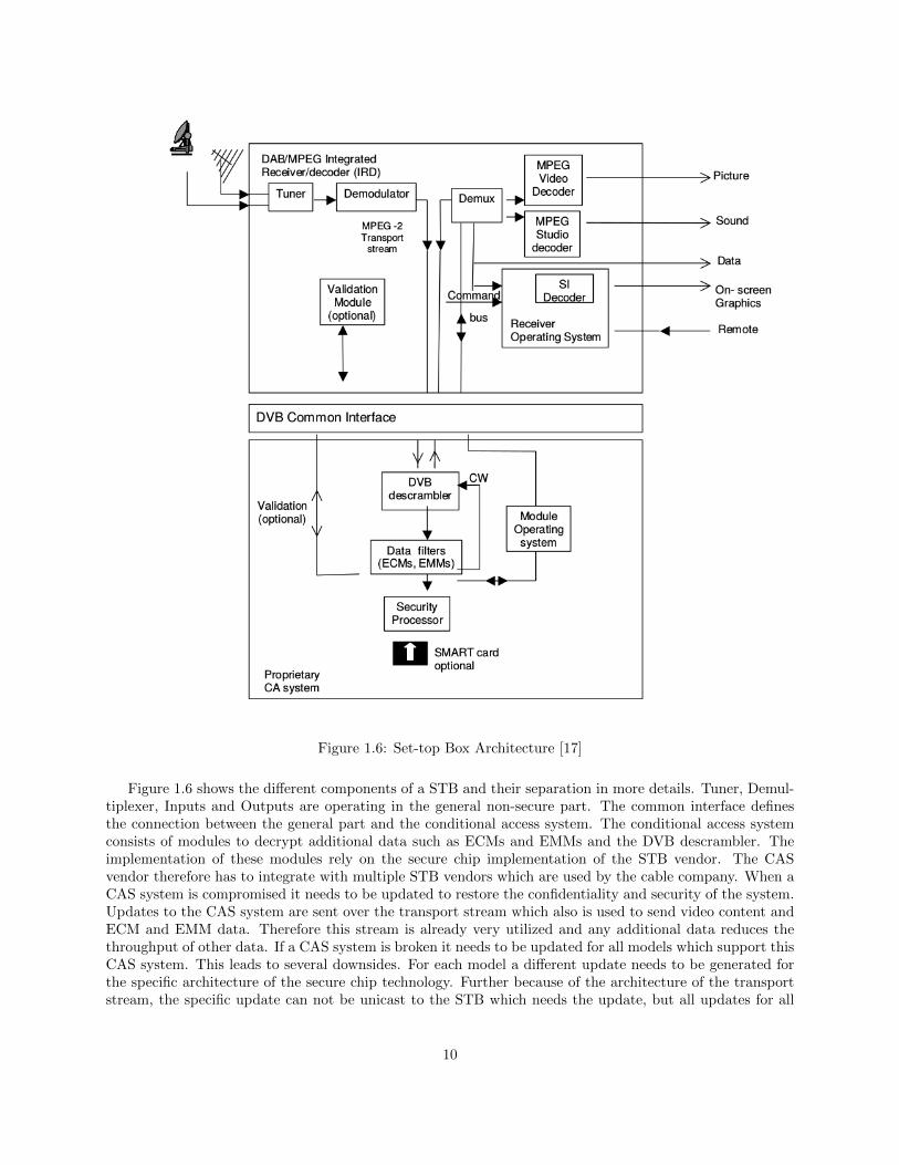
Figure 1.6: Set-top Box Architecture [17]
Figure 1.6 shows the different components of a STB and their separation in more details. Tuner, Demul-tiplexer, Inputs and Outputs are operating in the general non-secure part. The common interface definesthe connection between the general part and the conditional access system. The conditional access systemconsists of modules to decrypt additional data such as ECMs and EMMs and the DVB descrambler. Theimplementation of these modules rely on the secure chip implementation of the STB vendor. The CASvendor therefore has to integrate with multiple STB vendors which are used by the cable company. When aCAS system is compromised it needs to be updated to restore the confidentiality and security of the system.Updates to the CAS system are sent over the transport stream which also is used to send video content andECM and EMM data. Therefore this stream is already very utilized and any additional data reduces thethroughput of other data. If a CAS system is broken it needs to be updated for all models which support thisCAS system. This leads to several downsides. For each model a different update needs to be generated forthe specific architecture of the secure chip technology. Further because of the architecture of the transportstream, the specific update can not be unicast to the STB which needs the update, but all updates for all
10
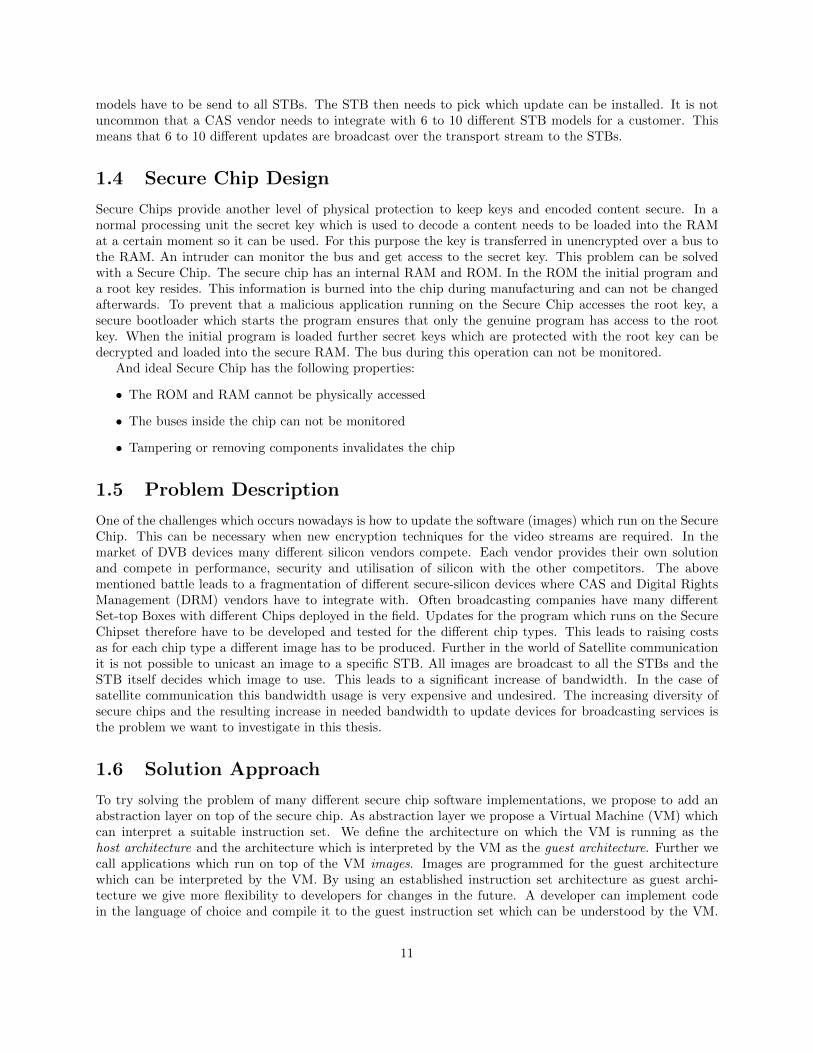
models have to be send to all STBs. The STB then needs to pick which update can be installed. It is notuncommon that a CAS vendor needs to integrate with 6 to 10 different STB models for a customer. Thismeans that 6 to 10 different updates are broadcast over the transport stream to the STBs.
1.4 Secure Chip Design
Secure Chips provide another level of physical protection to keep keys and encoded content secure. In anormal processing unit the secret key which is used to decode a content needs to be loaded into the RAMat a certain moment so it can be used. For this purpose the key is transferred in unencrypted over a bus tothe RAM. An intruder can monitor the bus and get access to the secret key. This problem can be solvedwith a Secure Chip. The secure chip has an internal RAM and ROM. In the ROM the initial program anda root key resides. This information is burned into the chip during manufacturing and can not be changedafterwards. To prevent that a malicious application running on the Secure Chip accesses the root key, asecure bootloader which starts the program ensures that only the genuine program has access to the rootkey. When the initial program is loaded further secret keys which are protected with the root key can bedecrypted and loaded into the secure RAM. The bus during this operation can not be monitored.
And ideal Secure Chip has the following properties:
• The ROM and RAM cannot be physically accessed
• The buses inside the chip can not be monitored
• Tampering or removing components invalidates the chip
1.5 Problem Description
One of the challenges which occurs nowadays is how to update the software (images) which run on the SecureChip. This can be necessary when new encryption techniques for the video streams are required. In themarket of DVB devices many different silicon vendors compete. Each vendor provides their own solutionand compete in performance, security and utilisation of silicon with the other competitors. The abovementioned battle leads to a fragmentation of different secure-silicon devices where CAS and Digital RightsManagement (DRM) vendors have to integrate with. Often broadcasting companies have many differentSet-top Boxes with different Chips deployed in the field. Updates for the program which runs on the SecureChipset therefore have to be developed and tested for the different chip types. This leads to raising costsas for each chip type a different image has to be produced. Further in the world of Satellite communicationit is not possible to unicast an image to a specific STB. All images are broadcast to all the STBs and theSTB itself decides which image to use. This leads to a significant increase of bandwidth. In the case ofsatellite communication this bandwidth usage is very expensive and undesired. The increasing diversity ofsecure chips and the resulting increase in needed bandwidth to update devices for broadcasting services isthe problem we want to investigate in this thesis.
1.6 Solution Approach
To try solving the problem of many different secure chip software implementations, we propose to add anabstraction layer on top of the secure chip. As abstraction layer we propose a Virtual Machine (VM) whichcan interpret a suitable instruction set. We define the architecture on which the VM is running as thehost architecture and the architecture which is interpreted by the VM as the guest architecture. Further wecall applications which run on top of the VM images. Images are programmed for the guest architecturewhich can be interpreted by the VM. By using an established instruction set architecture as guest archi-tecture we give more flexibility to developers for changes in the future. A developer can implement codein the language of choice and compile it to the guest instruction set which can be understood by the VM.
11
Further, by using already established instruction sets, common tools can be used to execute these tasks.As the virtual machine needs to be ported to several different host architectures, we decided to create anemulation VM written in C. This allows fast porting of the VM by just compiling it to the desired hostarchitecture. This will cause performance decrease, but the advantage of this solution is the portability ofthe VM to other secure chip architectures. Another advantage of the emulation approach is that it allowsto add further security measures. For example we added another encryption of the instructions of the imagewhich is running on the secure chip. With this approach the image can be loaded over an insecure channelto the secure chip and only the VM on the secure chip can decrypt and interpret the instructions of the image.
To evaluate the above described solution approach we want to answer the following research questions.
• Is it feasible to create an abstraction layer for Secure Chips to run applications on?
• What guest instruction set is suitable for the abstraction layer?
• How large is the code size overhead of the abstraction layer?
• How large is the execution time overhead of the abstraction layer?
For comparison we choose two guest instruction sets which can be intepreted by the VM. We decided touse two established Reduced Instruction Set Computing (RISC) architectures which allow us to use availabletools to create the images for the VM.
• MIPS (Microprocessor without Interlocked Pipeline Stages)
• ARM (Advanced RISC Machine)
1.7 Thesis Contribution
In this thesis we developed and run a virtual machine on top of a secure chip. We proved that it is possibleto run a virtual machine, as an abstraction layer, on a secure chip. To evaluate the execution time slowdownwe used the two platforms, Arduino and ST. Additionally we compared two different instruction sets, ARMand MIPS, from which the ARM instruction set proved to be more suitable. During the analysis of thecode size overhead, we discovered that the image size of ARM images are substantially smaller than nativeimages, which would lead to a drastic decrease of bandwidth usage. For example if a broadcaster uses theARM VM instead of four native applications, up to 80% of bandwidth usage for an application update canbe saved.
1.8 Related Work
In this section, we present related work in the field of media protection and virtual machines.
1.8.1 Self Protecting Digital Content
Self-Protecting Digital Content [8] was an architecture developed to secure digital content on optical discs andled to Blue-Ray Digital Right Management system BD+. In the time when optical drives were most popularfor content distribution, protecting and securing the content faced several problems. One of the problemswas the long live time of the devices and mediums and that the security measures which were for exampleimplemented for DVD were in the hardware and not updatable. When the security was compromised it wasnot possible to just easy install a new security measure. Another problem was that the device manufacturerswere not merely interested in creating the most secure devices as if the content was compromised it did notlead to less revenue for the device manufacturer but alone for the content provider. Moreover, less securedevices which were able to play DVD disregarding of the country code were more attractive for customers
12
to buy than more restrictive one. The content provider should have taken control to develop a securearchitecture. The above mentioned not ideal condition led to the not very successful DRM system for DVDscalled Content Scramble System (CSS). The system was introduced in 1996 and was first compromisedin 1999. CSS was implemented in the player with a fixed security policy for all content. With a validkey all media could be decrypted. To achieve this, the keys were preloaded in the device. One of thedesign flaws in CSS was that a proprietary cryptographic algorithm was used which proved to be trivial tobreak. But even though if a strong unbreakable known cryptographic algorithm would have been used oftenpoorly implemented key management allowed attackers to extract the keys without the need of breaking thecryptographic algorithm.
After the failure of CSS, a study proposed the solution of Self-Protecting Digital Content [8]. The ideais to include the security in the content itself and not implement it in the device. This would allow contentproviders to react to new threats. If a security system is compromised it would be only compromised for thespecific content. New content could include updated security measures without updating the player.
Figure 1.7: DVD protection [8]
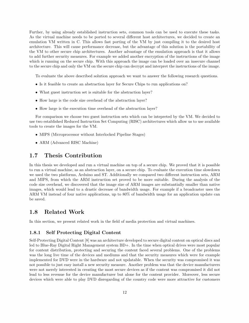
The proposed implementation consist of a virtual machine, as seen in Figure 1.7, which has access tocryptographic modules with keys. Further the virtual machine has an interface to the control unit and cancontrol how the content is decrypted and played to the output of the system. The code which determineshow the video content is decrypted is also on the disc and loaded in advance in a secure way to the ROMof the VM. This decrypting code resides on the VM and loads the content, decrypts it and sends it to theoutput of the device.
Even though this technology was developed for content on optical discs which are a little bit outdatednowadays, similar techniques can be adopted to the over the top content distribution. A VM on a device orin a software player can preload descramble information which is included in the content which is send tothe customer. The preloaded code includes the security measures which allow the user to see the content.
13
This technology also provided a virtual machine with many special system calls which allowed the de-velopers of the DRM software to access other components of the STB. The developed virtual machine wasdesigned for a special chip and was not designed for portability. The main goal was not to emulate a differentinstruction set but to offer a platform to content providers to secure their content.
The goal of our VM on the other hand is to emulate a guest instruction set and to allow the VM to beported to different hosts architectures easily.
1.8.2 Terra Trusted Virtual Machine
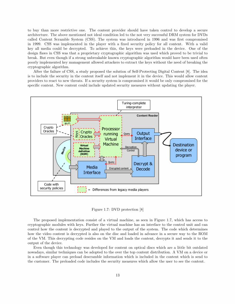
Terra [6] is a trusted virtual machine which solved the problem of how applications are secured on a modernoperating system. Operating systems usually contain millions of lines of code and applications built on tophave to rely on the security of the operating system. Further applications running on these systems areoften not securely isolated from each other. Another problem addressed by Terra is how applications canbe authenticated to verify the identity of the program. At the heart of Terra is a Trusted Virtual MachineMonitor (TVMM), which partitions a single tamper-resistant, general-purpose platform in multiple isolatedvirtual machines. Terra provides the property to authenticate the software running in the VM to remoteparties, hence the name trusted virtual machine monitor.
Figure 1.8: Terra [6]
As shown in the figure the TVMM runs directly on the hardware and each application can run on his ownoperating system. This offers much freedom to the developers. The applications are then authenticated bythe TVMM and can communicated to other applications running on the TVMM in a secure way. Althoughthis approach offers interesting security features, the concept relies on powerful hardware and seems not tobe an appropriate solution to run on secure chipsets.
1.8.3 Virtual Machine for Microcontrollers
Virtual machines were also considered for microcontrollers [5]. To find a suitable virtual machine for micro-contollers is not that trivial though. Therefore several small virtual machines were evaluated for this task.Microcontrollers have very small capacities, usually about 128-256K of flash memory and 128K of RAM.Therefore a virtual machine which performs well on a microcontroller would also be a good candidate as avirtual machine for secure chips. In the paper several VMs are evaluated.
14
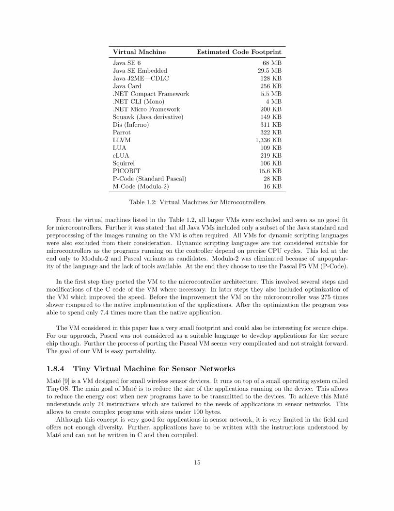
Virtual Machine Estimated Code Footprint
Java SE 6 68 MBJava SE Embedded 29.5 MBJava J2ME—CDLC 128 KBJava Card 256 KB.NET Compact Framework 5.5 MB.NET CLI (Mono) 4 MB.NET Micro Framework 200 KBSquawk (Java derivative) 149 KBDis (Inferno) 311 KBParrot 322 KBLLVM 1,336 KBLUA 109 KBeLUA 219 KBSquirrel 106 KBPICOBIT 15.6 KBP-Code (Standard Pascal) 28 KBM-Code (Modula-2) 16 KB
Table 1.2: Virtual Machines for Microcontrollers
From the virtual machines listed in the Table 1.2, all larger VMs were excluded and seen as no good fitfor microcontrollers. Further it was stated that all Java VMs included only a subset of the Java standard andpreprocessing of the images running on the VM is often required. All VMs for dynamic scripting languageswere also excluded from their consideration. Dynamic scripting languages are not considered suitable formicrocontrollers as the programs running on the controller depend on precise CPU cycles. This led at theend only to Modula-2 and Pascal variants as candidates. Modula-2 was eliminated because of unpopular-ity of the language and the lack of tools available. At the end they choose to use the Pascal P5 VM (P-Code).
In the first step they ported the VM to the microcontroller architecture. This involved several steps andmodifications of the C code of the VM where necessary. In later steps they also included optimization ofthe VM which improved the speed. Before the improvement the VM on the microcontroller was 275 timesslower compared to the native implementation of the applications. After the optimization the program wasable to spend only 7.4 times more than the native application.
The VM considered in this paper has a very small footprint and could also be interesting for secure chips.For our approach, Pascal was not considered as a suitable language to develop applications for the securechip though. Further the process of porting the Pascal VM seems very complicated and not straight forward.The goal of our VM is easy portability.
1.8.4 Tiny Virtual Machine for Sensor Networks
Mate [9] is a VM designed for small wireless sensor devices. It runs on top of a small operating system calledTinyOS. The main goal of Mate is to reduce the size of the applications running on the device. This allowsto reduce the energy cost when new programs have to be transmitted to the devices. To achieve this Mateunderstands only 24 instructions which are tailored to the needs of applications in sensor networks. Thisallows to create complex programs with sizes under 100 bytes.
Although this concept is very good for applications in sensor network, it is very limited in the field andoffers not enough diversity. Further, applications have to be written with the instructions understood byMate and can not be written in C and then compiled.
15
1.8.5 ARM TrustZone
ARM defined an approach how security can be implemented on a System on a Chip (SoC). ARM TrustZoneis part of version 8 of the ARM instruction set and provides a Trusted Execution Environment (TEE). TEEis discussed in Section 2.4. SoC vendors and OEMs can implement the framework according to a referenceimplementation which is provided open source by ARM.
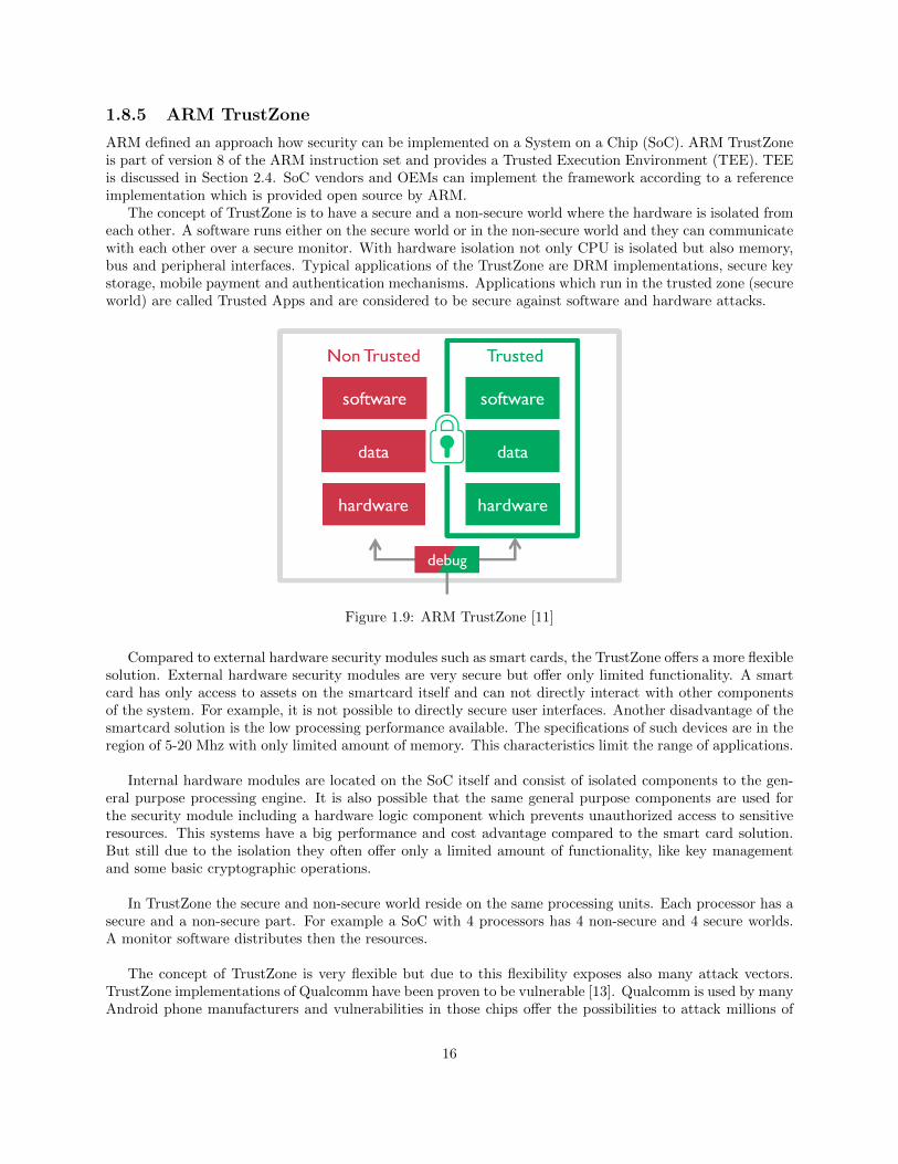
The concept of TrustZone is to have a secure and a non-secure world where the hardware is isolated fromeach other. A software runs either on the secure world or in the non-secure world and they can communicatewith each other over a secure monitor. With hardware isolation not only CPU is isolated but also memory,bus and peripheral interfaces. Typical applications of the TrustZone are DRM implementations, secure keystorage, mobile payment and authentication mechanisms. Applications which run in the trusted zone (secureworld) are called Trusted Apps and are considered to be secure against software and hardware attacks.
Figure 1.9: ARM TrustZone [11]
Compared to external hardware security modules such as smart cards, the TrustZone offers a more flexiblesolution. External hardware security modules are very secure but offer only limited functionality. A smartcard has only access to assets on the smartcard itself and can not directly interact with other componentsof the system. For example, it is not possible to directly secure user interfaces. Another disadvantage of thesmartcard solution is the low processing performance available. The specifications of such devices are in theregion of 5-20 Mhz with only limited amount of memory. This characteristics limit the range of applications.
Internal hardware modules are located on the SoC itself and consist of isolated components to the gen-eral purpose processing engine. It is also possible that the same general purpose components are used forthe security module including a hardware logic component which prevents unauthorized access to sensitiveresources. This systems have a big performance and cost advantage compared to the smart card solution.But still due to the isolation they often offer only a limited amount of functionality, like key managementand some basic cryptographic operations.
In TrustZone the secure and non-secure world reside on the same processing units. Each processor has asecure and a non-secure part. For example a SoC with 4 processors has 4 non-secure and 4 secure worlds.A monitor software distributes then the resources.
The concept of TrustZone is very flexible but due to this flexibility exposes also many attack vectors.TrustZone implementations of Qualcomm have been proven to be vulnerable [13]. Qualcomm is used by manyAndroid phone manufacturers and vulnerabilities in those chips offer the possibilities to attack millions of
16
phones.A further problem of the Qualcomm solution was that the images for the secure world are not encrypted.
This allowed researchers to reverse engineer the code and find attack vectors in the code.
ARM TrustZone is an interesting concept for secure applications but are limited to ARM Architecturechips. In the world of STBs many different chip vendors are present. The CAS vendor would rely that eachchip vendor implements ARM TrustZone. Our solution on the other hand tries exactly to cicrumvent thisproblem. Moreover, our virtual machine could be used as abstraction layer on top of the ARM Trustzone.
17
Chapter 2
Background
For the abstraction layer between the secure chip and the application running on the chip we will create avirtual machine. The concept of virtual machines is closer discussed in this chapter. Further we discuss theinstruction sets we considered for our virtual machine. Additionally, we also give some detailed informationabout Trusted Execution Environment (TEE). Some secure chip manufacturers, for example ST, implementthe TEE standard to provide an interface between unsecure applications and secure applications running onthe secure chip.
2.1 Virtual Machines
In early stages of computer development, the hardware was designed first and the software was later devel-oped specifically for the hardware. These programs where quite simple but could not be interchanged toother hardware architectures. Quickly, it became evident that software compatibility and portability is veryimportant. To accomplish this, the Instruction Set Architecture (ISA) was introduced. The ISA defined theinterface between hardware and software precisely and allowed to run programs on different hardware if thesame architecture was supported. This was already a big improvement. The problem still existed thoughthat different ISAs emerged and programs compiled for one ISA could not be run on hardware of anotherarchitecture. In addition, operating systems were developed which manage the hardware resources and allowsimplification of writing applications which run on top of the operating system. The operating system there-fore exposes interfaces to the application developers. This added another problem that programs written forone operating system can not be used on a different operating system. This limitation can be circumventedwith the help of a Virtual Machine (VM) [14]. The VM adds another layer between the underlying platformand the software to be executed. The VM thereby appears to the software as the platform required to runthe program. This can either be a specific ISA or a full operating system.
In Figure 2.1 such a layer is shown between the hardware and the operating system and application. Weshall name this layer virtualizing software or Virtual Machine Monitor (VMM). As shown in the figure theapplication which needs to be executed either uses the Application Binary Interface (ABI) interface of theoperating system or an privileged instructions to access hardware resources. The VMM intercepts privilegedinstructions to manage shared access to hardware resources. For the guest application it seems a direct callto the hardware resource was performed. Additionally the VMM virtualizes the ISA which is expected bythe operating system and the application. We define the platform on which the VMM runs the host platformwhich provides the host ISA. The operating system or application which runs on top of the VMM we defineas the guest system. Guest applications therefore expect the guest ISA.
18
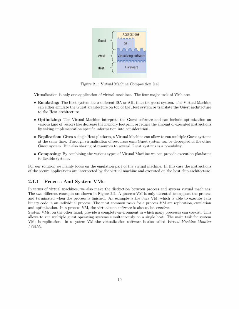
Figure 2.1: Virtual Machine Composition [14]
Virtualisation is only one application of virtual machines. The four major task of VMs are:
• Emulating: The Host system has a different ISA or ABI than the guest system. The Virtual Machinecan either emulate the Guest architecture on top of the Host system or translate the Guest architectureto the Host architecture.
• Optimizing: The Virtual Machine interprets the Guest software and can include optimization onvarious kind of vectors like decrease the memory footprint or reduce the amount of executed instructionsby taking implementation specific information into consideration.
• Replication: Given a single Host platform, a Virtual Machine can allow to run multiple Guest systemsat the same time. Through virtualisation of resources each Guest system can be decoupled of the otherGuest system. But also sharing of resources to several Guest systems is a possibility.
• Composing: By combining the various types of Virtual Machine we can provide execution platformsto flexible systems.
For our solution we mainly focus on the emulation part of the virtual machine. In this case the instructionsof the secure applications are interpreted by the virtual machine and executed on the host chip architecture.
2.1.1 Process And System VMs
In terms of virtual machines, we also make the distinction between process and system virtual machines.The two different concepts are shown in Figure 2.2. A process VM is only executed to support the processand terminated when the process is finished. An example is the Java VM, which is able to execute Javabinary code in an individual process. The most common tasks for a process VM are replication, emulationand optimization. In a process VM, the virtualizion software is also called runtime.System VMs, on the other hand, provide a complete environment in which many processes can coexist. Thisallows to run multiple guest operating systems simultaneously on a single host. The main task for systemVMs is replication. In a system VM the virtualization software is also called Virtual Machine Monitor(VMM).
19
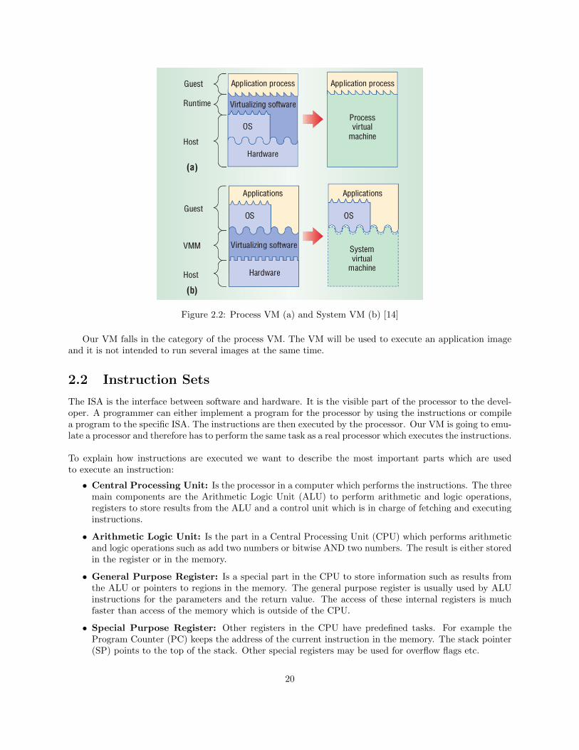
Figure 2.2: Process VM (a) and System VM (b) [14]
Our VM falls in the category of the process VM. The VM will be used to execute an application imageand it is not intended to run several images at the same time.
2.2 Instruction Sets
The ISA is the interface between software and hardware. It is the visible part of the processor to the devel-oper. A programmer can either implement a program for the processor by using the instructions or compilea program to the specific ISA. The instructions are then executed by the processor. Our VM is going to emu-late a processor and therefore has to perform the same task as a real processor which executes the instructions.
To explain how instructions are executed we want to describe the most important parts which are usedto execute an instruction:
• Central Processing Unit: Is the processor in a computer which performs the instructions. The threemain components are the Arithmetic Logic Unit (ALU) to perform arithmetic and logic operations,registers to store results from the ALU and a control unit which is in charge of fetching and executinginstructions.
• Arithmetic Logic Unit: Is the part in a Central Processing Unit (CPU) which performs arithmeticand logic operations such as add two numbers or bitwise AND two numbers. The result is either storedin the register or in the memory.
• General Purpose Register: Is a special part in the CPU to store information such as results fromthe ALU or pointers to regions in the memory. The general purpose register is usually used by ALUinstructions for the parameters and the return value. The access of these internal registers is muchfaster than access of the memory which is outside of the CPU.
• Special Purpose Register: Other registers in the CPU have predefined tasks. For example theProgram Counter (PC) keeps the address of the current instruction in the memory. The stack pointer(SP) points to the top of the stack. Other special registers may be used for overflow flags etc.
20
• Stack: Is a special region in the memory which is used to keep information about subroutines. Forexample when a function is called the parameters of the function and the return address, from wherethe function is called are pushed to the stack. The subroutine can then read the parameters from thestack and when it is finished use the return address to go back from the caller. As the name indicatesthe stack uses LIFO (last in first out) data structure. Usually the stack is initialized by the operatingsystem and has a limit. A stack overflow happens when the stack limit is exceeded, for example whentoo many subroutines are called.
• Heap: Is a region in the memory which can be used by a program but is not structured. To usememory in the heap the program needs to allocate memory and free it when it is not used anymore.A memory leak is the situation when a program forgets to free the unused memory and therefore theregion will not be available for other programs. These can lead that the whole memory is exceededand the computer may crash.
The main tasks of the processor are fetching an instruction from the memory, decoding the instructionand executing the instruction. To perform all these tasks the registers, the ALU and the stack are utilized.Our VM emulates a processor and therefore has to perform the same tasks with a virtual register and stack.Where the input operands have to be stored to execute an ALU instruction is defined by the ISA type. Overtime different versions where developed which used different components for calculations. The three mostcommon types are:
• Stack ISA: The operands for the ALU are implicitly pushed to the stack. The ALU then performsthe operations directly with the values from the stack.
• Accumulator ISA: Uses a special register, the accumulator, in the CPU to store one operand implicit.The ALU then can use this accumulator and another input value to perform operations.
• General Purpose Register ISA: All operands are mentioned in the instruction explicitly. They arestored either in the memory or on the register beforehand. The CPU offers for this several generalpurpose register which can be used. An architecture which allows that the operand is in memory orregister is also called register memory architecture. An architecture which only allows operands to bein register is called register register architecture.
From the three above mentioned architectures the general purpose register architecture is the mostsuccessful one and is used almost exclusively in modern computers. Beside of differences where the operandsare stored for the ALU, architectures also differ by instruction design. Two main architectures with differentinstruction designs are known today.
• Complex Instruction Set Computing (CISC): Is a processor design where a single instructioncan execute several low level instructions at the same time. The design principle was to reduce theamount of instructions which the processor has to perform and support higher level programmingconstructs directly on instruction level. This has the advantage that less instructions are needed andthe resulting program is smaller. These type of instructions sets have a large amount of instructionswhereby instructions are added over time and have variable length. Further complex instructionscan use several clock cycles in this architecture. This makes it difficult to optimize the order of theexecution of instructions.
• Reduced Instruction Set Computing (RISC): Follows a different design principle than CISC. Itwas suggested that a smaller instruction set, where each instruction uses only one clock cycle, can easierbe optimized and at the end achieves a better performance than a processor with CISC architecture.Therefore, the reduced instruction set was developed, whereby ”reduced” does not refer to lesserinstructions but the amount of work a processor has to perform compared to complex instructions.Another feature is that commonly RISC instructions have a fixed length which simplifies fetch, decodeand execution logic on the processor. This allows to produce processors with less transistors compared
21
to CISC but more registers and increase internal parallelism. One drawback of the RISC architectureis that usually more instructions are needed to complete the same task as one complex instructionwhich results in larger application sizes.
As RISC instructions are in general smaller and simpler to decode, we decided to use this architecturefor our VM. This will also help to keep the VM implementation small enough for our target processor.
2.2.1 MIPS Instruction Set
MIPS stands for Microprocessor without Interlocked Pipeline Stages and is a reduced instruction set com-puter architecture (RISC) originally developed by researchers from the Stanford University which later onfounded the company MIPS Technologies. MIPS is a register-register architecture in which operands haveto be stored explicitly in the registers before they can be used by the ALU. To access the memory, load andstore operations are needed. Over the years several versions were developed from MIPS I until MIPS V andlater on MIPS 32 and MIPS 64. The original MIPS ISA I to V has been extended in a backward compatiblefashion. That means all MIPS I instructions where also valid in MIPS II to V. This had the advantage thatprograms which run on a MIPS I processor, run also on a MIPS V processor. 64-bit integers and addresseswere added in MIPS III. MIPS was first intended for computer like environments but later on had moresuccess in the embedded market. Embedded systems have different requirements in regard to memory usageand performance. MIPS 32 and MIPS 64 are intended to address this needs. MIPS 32 was then based onMIPS II, which did not support any 64 bit instructions, and MIPS 64 on MIPS V.
For simplicity reasons we decided to implement MIPS I ISA in our VM which consists of 61 instructions.For this reason when a program for the VM is compiled, we have to specify that only MIPS I instructionsare allowed. The MIPS I instructions are defined in the reference manual [7] from MIPS. All instructionswhich are included in MIPS I and are implemented in the MIPS VM are listed in appendix A.
MIPS Registers
MIPS has 32 registers. The registers are used by the current executed instruction to store parameters andreturn values, but also to store pointers to the stack etc.
Number Name Usage
0 $zero constant value 01 $at reserved for the assembler2-3 $v0-$v1 values for results and expressions4-7 $a0-$a3 arguments (procedures / functions)8-15 $t0-$t7 temporaries76-23 $s0-$s7 saved24-25 $t8-$t9 more temporaries26-27 $k0-$k1 reserved for the operating system28 $gp global pointer29 $sp stack pointer30 $fp frame pointer31 $ra return address
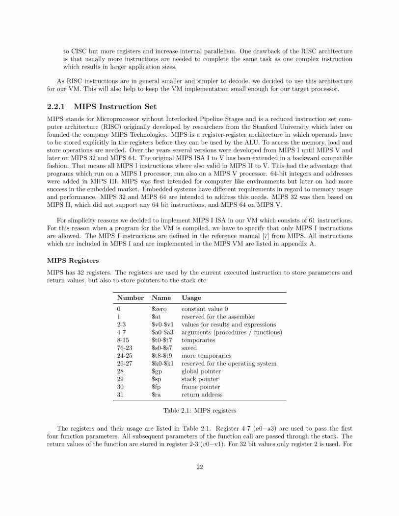
Table 2.1: MIPS registers
The registers and their usage are listed in Table 2.1. Register 4-7 (a0−a3) are used to pass the firstfour function parameters. All subsequent parameters of the function call are passed through the stack. Thereturn values of the function are stored in register 2-3 (v0−v1). For 32 bit values only register 2 is used. For
22
64 bit return values, both return registers are used. The stack pointer is set to the top of the stack at thebeginning of a program and grows down when values are added to the stack.
MIPS Instructions
MIPS I includes 61 instructions which we can be divided in four categories. Load and store instructions,arithmetic and logic operations, jump and branch instructions and miscellaneous instructions.
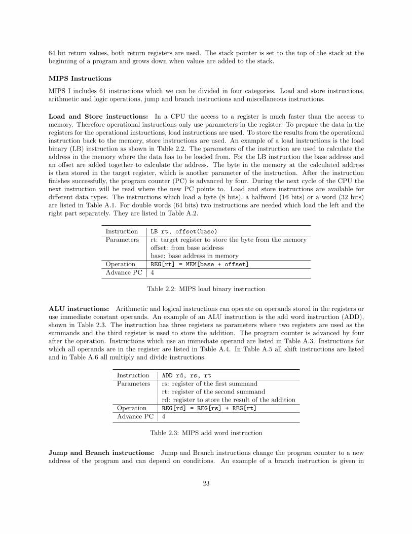
Load and Store instructions: In a CPU the access to a register is much faster than the access tomemory. Therefore operational instructions only use parameters in the register. To prepare the data in theregisters for the operational instructions, load instructions are used. To store the results from the operationalinstruction back to the memory, store instructions are used. An example of a load instructions is the loadbinary (LB) instruction as shown in Table 2.2. The parameters of the instruction are used to calculate theaddress in the memory where the data has to be loaded from. For the LB instruction the base address andan offset are added together to calculate the address. The byte in the memory at the calculated addressis then stored in the target register, which is another parameter of the instruction. After the instructionfinishes successfully, the program counter (PC) is advanced by four. During the next cycle of the CPU thenext instruction will be read where the new PC points to. Load and store instructions are available fordifferent data types. The instructions which load a byte (8 bits), a halfword (16 bits) or a word (32 bits)are listed in Table A.1. For double words (64 bits) two instructions are needed which load the left and theright part separately. They are listed in Table A.2.
Instruction LB rt, offset(base)
Parameters rt: target register to store the byte from the memoryoffset: from base addressbase: base address in memory
Operation REG[rt] = MEM[base + offset]
Advance PC 4
Table 2.2: MIPS load binary instruction
ALU instructions: Arithmetic and logical instructions can operate on operands stored in the registers oruse immediate constant operands. An example of an ALU instruction is the add word instruction (ADD),shown in Table 2.3. The instruction has three registers as parameters where two registers are used as thesummands and the third register is used to store the addition. The program counter is advanced by fourafter the operation. Instructions which use an immediate operand are listed in Table A.3. Instructions forwhich all operands are in the register are listed in Table A.4. In Table A.5 all shift instructions are listedand in Table A.6 all multiply and divide instructions.
Instruction ADD rd, rs, rt
Parameters rs: register of the first summandrt: register of the second summandrd: register to store the result of the addition
Operation REG[rd] = REG[rs] + REG[rt]
Advance PC 4
Table 2.3: MIPS add word instruction
Jump and Branch instructions: Jump and Branch instructions change the program counter to a newaddress of the program and can depend on conditions. An example of a branch instruction is given in
23
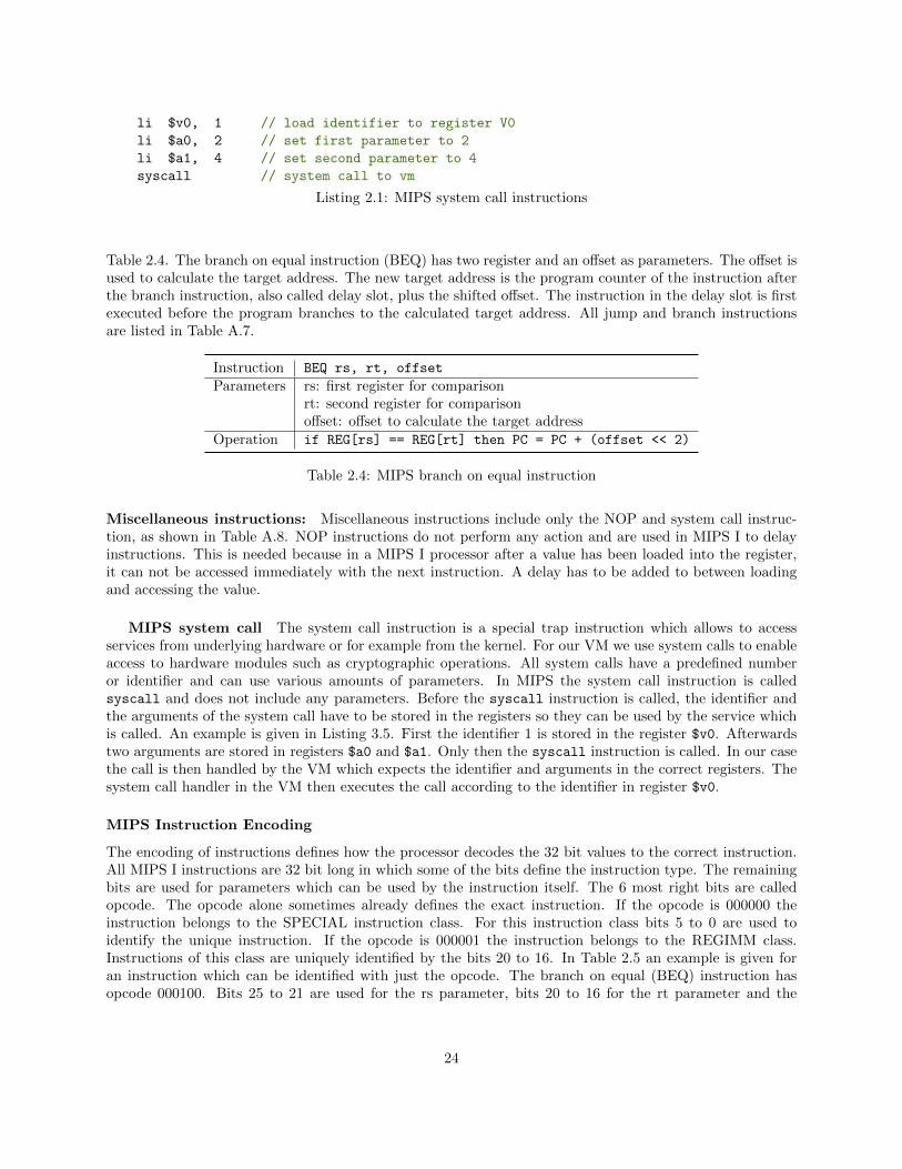
li $v0, 1 // load identifier to register V0
li $a0, 2 // set first parameter to 2
li $a1, 4 // set second parameter to 4
syscall // system call to vm
Listing 2.1: MIPS system call instructions
Table 2.4. The branch on equal instruction (BEQ) has two register and an offset as parameters. The offset isused to calculate the target address. The new target address is the program counter of the instruction afterthe branch instruction, also called delay slot, plus the shifted offset. The instruction in the delay slot is firstexecuted before the program branches to the calculated target address. All jump and branch instructionsare listed in Table A.7.
Instruction BEQ rs, rt, offset
Parameters rs: first register for comparisonrt: second register for comparisonoffset: offset to calculate the target address
Operation if REG[rs] == REG[rt] then PC = PC + (offset << 2)
Table 2.4: MIPS branch on equal instruction
Miscellaneous instructions: Miscellaneous instructions include only the NOP and system call instruc-tion, as shown in Table A.8. NOP instructions do not perform any action and are used in MIPS I to delayinstructions. This is needed because in a MIPS I processor after a value has been loaded into the register,it can not be accessed immediately with the next instruction. A delay has to be added to between loadingand accessing the value.
MIPS system call The system call instruction is a special trap instruction which allows to accessservices from underlying hardware or for example from the kernel. For our VM we use system calls to enableaccess to hardware modules such as cryptographic operations. All system calls have a predefined numberor identifier and can use various amounts of parameters. In MIPS the system call instruction is calledsyscall and does not include any parameters. Before the syscall instruction is called, the identifier andthe arguments of the system call have to be stored in the registers so they can be used by the service whichis called. An example is given in Listing 3.5. First the identifier 1 is stored in the register $v0. Afterwardstwo arguments are stored in registers $a0 and $a1. Only then the syscall instruction is called. In our casethe call is then handled by the VM which expects the identifier and arguments in the correct registers. Thesystem call handler in the VM then executes the call according to the identifier in register $v0.
MIPS Instruction Encoding
The encoding of instructions defines how the processor decodes the 32 bit values to the correct instruction.All MIPS I instructions are 32 bit long in which some of the bits define the instruction type. The remainingbits are used for parameters which can be used by the instruction itself. The 6 most right bits are calledopcode. The opcode alone sometimes already defines the exact instruction. If the opcode is 000000 theinstruction belongs to the SPECIAL instruction class. For this instruction class bits 5 to 0 are used toidentify the unique instruction. If the opcode is 000001 the instruction belongs to the REGIMM class.Instructions of this class are uniquely identified by the bits 20 to 16. In Table 2.5 an example is given foran instruction which can be identified with just the opcode. The branch on equal (BEQ) instruction hasopcode 000100. Bits 25 to 21 are used for the rs parameter, bits 20 to 16 for the rt parameter and the
24
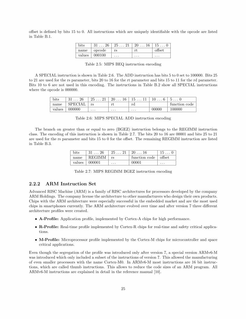
offset is defined by bits 15 to 0. All instructions which are uniquely identifiable with the opcode are listedin Table B.1.
bits 31 . . . 26 25 . . . 21 20 . . . 16 15 . . . 0name opcode rs rt offsetvalues 000100 . . . . . . . . .
Table 2.5: MIPS BEQ instruction encoding
A SPECIAL instruction is shown in Table 2.6. The ADD instruction has bits 5 to 0 set to 100000. Bits 25to 21 are used for the rs parameter, bits 20 to 16 for the rt parameter and bits 15 to 11 for the rd parameter.Bits 10 to 6 are not used in this encoding. The instructions in Table B.2 show all SPECIAL instructionswhere the opcode is 000000.
bits 31 . . . 26 25 . . . 21 20 . . . 16 15 . . . 11 10 . . . 6 5 . . . 0name SPECIAL rs rt rd function codevalues 000000 . . . . . . . . . 00000 100000
Table 2.6: MIPS SPECIAL ADD instruction encoding
The branch on greater than or equal to zero (BGEZ) instruction belongs to the REGIMM instructionclass. The encoding of this instruction is shown in Table 2.7. The bits 20 to 16 are 00001 and bits 25 to 21are used for the rs parameter and bits 15 to 0 for the offset. The remaining REGIMM instruction are listedin Table B.3.
bits 31 . . . 26 25 . . . 21 20 . . . 16 15 . . . 0name REGIMM rs function code offsetvalues 000001 . . . 00001 . . .
Table 2.7: MIPS REGIMM BGEZ instruction encoding
2.2.2 ARM Instruction Set
Advanced RISC Machine (ARM) is a family of RISC architectures for processors developed by the companyARM Holdings. The company license the architecture to other manufacturers who design their own products.Chips with the ARM architecture were especially successful in the embedded market and are the most usedchips in smartphones currently. The ARM architecture evolved over time and after version 7 three differentarchitecture profiles were created.
• A-Profile: Application profile, implemented by Cortex-A chips for high performance.
• R-Profile: Real-time profile implemented by Cortex-R chips for real-time and safety critical applica-tions.
• M-Profile: Microprocessor profile implemented by the Cortex-M chips for microcontroller and spacecritical applications.
Even though the segregation of the profile was introduced only after version 7, a special version ARMv6-Mwas introduced which only included a subset of the instructions of version 7. This allowed the manufacturingof even smaller processors with the name Cortex-M0. In ARMv6-M most instructions are 16 bit instruc-tions, which are called thumb instructions. This allows to reduce the code sizes of an ARM program. AllARMv6-M instructions are explained in detail in the reference manual [10].
25
We choose to implement the ARMv6-M instruction set for our VM which will allow to create smallerimages. For simplicity reasons our VM will support the same instructions as the Cortex-M0 chip. All ARMinstructions which are implemented in our VM are listed in Appendix C.
ARM Register
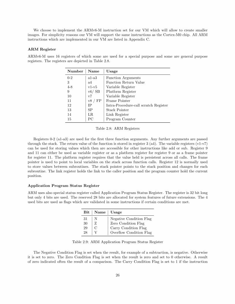
ARMv6-M uses 16 registers of which some are used for a special purpose and some are general purposeregisters. The registers are depicted in Table 2.8.
Number Name Usage
0-2 a1-a3 Function Arguments3 a4 Function Return Value4-8 v1-v5 Variable Register9 v6/ SB Platform Register10 v7 Variable Register11 v8 / FP Frame Pointer12 IP Intra-Procedure-call scratch Register13 SP Stack Pointer14 LR Link Register15 PC Program Counter
Table 2.8: ARM Registers
Registers 0-2 (a1-a3) are used for the first three function arguments. Any further arguments are passedthrough the stack. The return value of the function is stored in register 3 (a4). The variable registers (v1-v7)can be used for storing values which then are accessible for other instructions like add or sub. Register 9and 11 can either be used as variable register or as a platform register for register 9 or as a frame pointerfor register 11. The platform register requires that the value held is persistent across all calls. The framepointer is used to point to local variables on the stack across function calls. Register 12 is normally usedto store values between subroutines. The stack pointer points to the stack position and changes for eachsubroutine. The link register holds the link to the caller position and the program counter hold the currentposition.
Application Program Status Register
ARM uses also special status register called Application Program Status Register. The register is 32 bit longbut only 4 bits are used. The reserved 28 bits are allocated for system features of future extensions. The 4used bits are used as flags which are validated in some instructions if certain conditions are met.
Bit Name Usage
31 N Negative Condition Flag30 Z Zero Condition Flag29 C Carry Condition Flag28 V Overflow Condition Flag
Table 2.9: ARM Application Program Status Register
The Negative Condition Flag is set when the result, for example of a subtraction, is negative. Otherwiseit is set to zero. The Zero Condition Flag is set when the result is zero and set to 0 otherwise. A resultof zero indicated often the result of a comparison. The Carry Condition Flag is set to 1 if the instruction
26
results in a carry condition, for example an unsigned overflow on an addition. The Overflow Condition Flagis set to 1 if the instruction results in an overflow condition, for example a signed overflow on an addition.
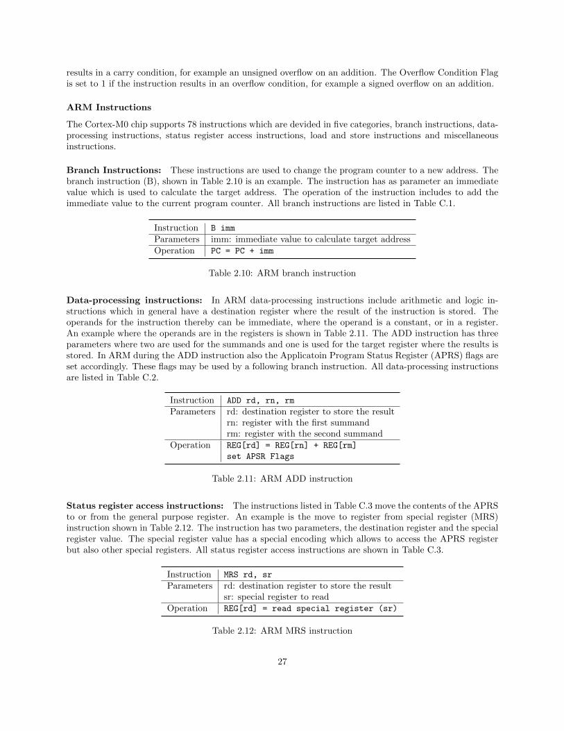
ARM Instructions
The Cortex-M0 chip supports 78 instructions which are devided in five categories, branch instructions, data-processing instructions, status register access instructions, load and store instructions and miscellaneousinstructions.
Branch Instructions: These instructions are used to change the program counter to a new address. Thebranch instruction (B), shown in Table 2.10 is an example. The instruction has as parameter an immediatevalue which is used to calculate the target address. The operation of the instruction includes to add theimmediate value to the current program counter. All branch instructions are listed in Table C.1.
Instruction B imm
Parameters imm: immediate value to calculate target addressOperation PC = PC + imm
Table 2.10: ARM branch instruction
Data-processing instructions: In ARM data-processing instructions include arithmetic and logic in-structions which in general have a destination register where the result of the instruction is stored. Theoperands for the instruction thereby can be immediate, where the operand is a constant, or in a register.An example where the operands are in the registers is shown in Table 2.11. The ADD instruction has threeparameters where two are used for the summands and one is used for the target register where the results isstored. In ARM during the ADD instruction also the Applicatoin Program Status Register (APRS) flags areset accordingly. These flags may be used by a following branch instruction. All data-processing instructionsare listed in Table C.2.
Instruction ADD rd, rn, rm
Parameters rd: destination register to store the resultrn: register with the first summandrm: register with the second summand
Operation REG[rd] = REG[rn] + REG[rm]
set APSR Flags
Table 2.11: ARM ADD instruction
Status register access instructions: The instructions listed in Table C.3 move the contents of the APRSto or from the general purpose register. An example is the move to register from special register (MRS)instruction shown in Table 2.12. The instruction has two parameters, the destination register and the specialregister value. The special register value has a special encoding which allows to access the APRS registerbut also other special registers. All status register access instructions are shown in Table C.3.
Instruction MRS rd, sr
Parameters rd: destination register to store the resultsr: special register to read
Operation REG[rd] = read special register (sr)
Table 2.12: ARM MRS instruction
27
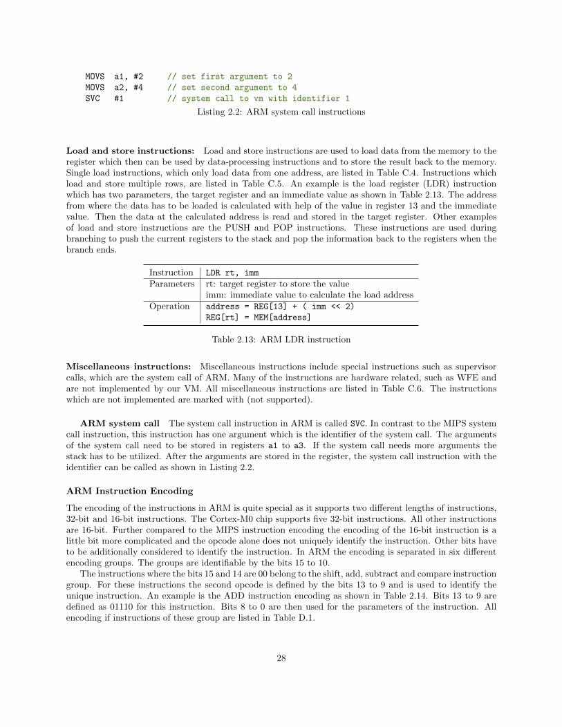
MOVS a1, #2 // set first argument to 2
MOVS a2, #4 // set second argument to 4
SVC #1 // system call to vm with identifier 1
Listing 2.2: ARM system call instructions
Load and store instructions: Load and store instructions are used to load data from the memory to theregister which then can be used by data-processing instructions and to store the result back to the memory.Single load instructions, which only load data from one address, are listed in Table C.4. Instructions whichload and store multiple rows, are listed in Table C.5. An example is the load register (LDR) instructionwhich has two parameters, the target register and an immediate value as shown in Table 2.13. The addressfrom where the data has to be loaded is calculated with help of the value in register 13 and the immediatevalue. Then the data at the calculated address is read and stored in the target register. Other examplesof load and store instructions are the PUSH and POP instructions. These instructions are used duringbranching to push the current registers to the stack and pop the information back to the registers when thebranch ends.
Instruction LDR rt, imm
Parameters rt: target register to store the valueimm: immediate value to calculate the load address
Operation address = REG[13] + ( imm << 2)
REG[rt] = MEM[address]
Table 2.13: ARM LDR instruction
Miscellaneous instructions: Miscellaneous instructions include special instructions such as supervisorcalls, which are the system call of ARM. Many of the instructions are hardware related, such as WFE andare not implemented by our VM. All miscellaneous instructions are listed in Table C.6. The instructionswhich are not implemented are marked with (not supported).
ARM system call The system call instruction in ARM is called SVC. In contrast to the MIPS systemcall instruction, this instruction has one argument which is the identifier of the system call. The argumentsof the system call need to be stored in registers a1 to a3. If the system call needs more arguments thestack has to be utilized. After the arguments are stored in the register, the system call instruction with theidentifier can be called as shown in Listing 2.2.
ARM Instruction Encoding
The encoding of the instructions in ARM is quite special as it supports two different lengths of instructions,32-bit and 16-bit instructions. The Cortex-M0 chip supports five 32-bit instructions. All other instructionsare 16-bit. Further compared to the MIPS instruction encoding the encoding of the 16-bit instruction is alittle bit more complicated and the opcode alone does not uniquely identify the instruction. Other bits haveto be additionally considered to identify the instruction. In ARM the encoding is separated in six differentencoding groups. The groups are identifiable by the bits 15 to 10.
The instructions where the bits 15 and 14 are 00 belong to the shift, add, subtract and compare instructiongroup. For these instructions the second opcode is defined by the bits 13 to 9 and is used to identify theunique instruction. An example is the ADD instruction encoding as shown in Table 2.14. Bits 13 to 9 aredefined as 01110 for this instruction. Bits 8 to 0 are then used for the parameters of the instruction. Allencoding if instructions of these group are listed in Table D.1.
28
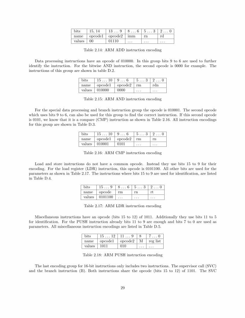
bits 15, 14 13 . . . 9 8 . . . 6 5 . . . 3 2 . . . 0name opcode1 opcode2 imm rn rdvalues 00 01110 . . . . . . . . .
Table 2.14: ARM ADD instruction encoding
Data processing instructions have an opcode of 010000. In this group bits 9 to 6 are used to furtheridentify the instruction. For the bitwise AND instruction, the second opcode is 0000 for example. Theinstructions of this group are shown in table D.2.
bits 15 . . . 10 9 . . . 6 5 . . . 3 2 . . . 0name opcode1 opcode2 rm rdnvalues 010000 0000 . . . . . .
Table 2.15: ARM AND instruction encoding
For the special data processing and branch instruction group the opcode is 010001. The second opcodewhich uses bits 9 to 6, can also be used for this group to find the correct instruction. If this second opcodeis 0101, we know that it is a compare (CMP) instruction as shown in Table 2.16. All instruction encodingsfor this group are shown in Table D.3.
bits 15 . . . 10 9 . . . 6 5 . . . 3 2 . . . 0name opcode1 opcode2 rm rnvalues 010001 0101 . . . . . .
Table 2.16: ARM CMP instruction encoding
Load and store instructions do not have a common opcode. Instead they use bits 15 to 9 for theirencoding. For the load register (LDR) instruction, this opcode is 0101100. All other bits are used for theparameters as shown in Table 2.17. The instructions where bits 15 to 9 are used for identification, are listedin Table D.4.
bits 15 . . . 9 8 . . . 6 5 . . . 3 2 . . . 0name opcode rm rn rtvalues 0101100 . . . . . . . . .
Table 2.17: ARM LDR instruction encoding
Miscellaneous instructions have an opcode (bits 15 to 12) of 1011. Additionally they use bits 11 to 5for identification. For the PUSH instruction already bits 11 to 9 are enough and bits 7 to 0 are used asparameters. All miscellaneous instruction encodings are listed in Table D.5.
bits 15 . . . 12 11 . . . 9 8 7 . . . 0name opcode1 opcode2 M reg listvalues 1011 010 . . . . . .
Table 2.18: ARM PUSH instruction encoding
The last encoding group for 16-bit instructions only includes two instructions. The supervisor call (SVC)and the branch instruction (B). Both instructions share the opcode (bits 15 to 12) of 1101. The SVC
29
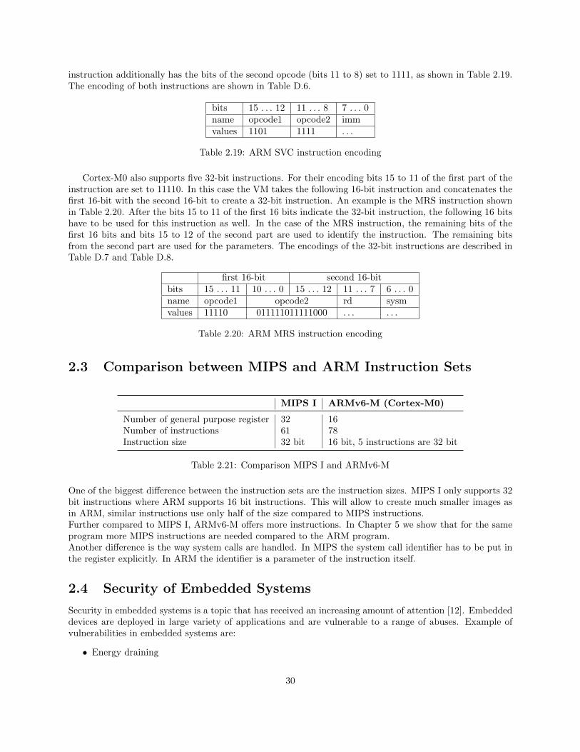
instruction additionally has the bits of the second opcode (bits 11 to 8) set to 1111, as shown in Table 2.19.The encoding of both instructions are shown in Table D.6.
bits 15 . . . 12 11 . . . 8 7 . . . 0name opcode1 opcode2 immvalues 1101 1111 . . .
Table 2.19: ARM SVC instruction encoding
Cortex-M0 also supports five 32-bit instructions. For their encoding bits 15 to 11 of the first part of theinstruction are set to 11110. In this case the VM takes the following 16-bit instruction and concatenates thefirst 16-bit with the second 16-bit to create a 32-bit instruction. An example is the MRS instruction shownin Table 2.20. After the bits 15 to 11 of the first 16 bits indicate the 32-bit instruction, the following 16 bitshave to be used for this instruction as well. In the case of the MRS instruction, the remaining bits of thefirst 16 bits and bits 15 to 12 of the second part are used to identify the instruction. The remaining bitsfrom the second part are used for the parameters. The encodings of the 32-bit instructions are described inTable D.7 and Table D.8.
first 16-bit second 16-bitbits 15 . . . 11 10 . . . 0 15 . . . 12 11 . . . 7 6 . . . 0name opcode1 opcode2 rd sysmvalues 11110 011111011111000 . . . . . .
Table 2.20: ARM MRS instruction encoding
2.3 Comparison between MIPS and ARM Instruction Sets
MIPS I ARMv6-M (Cortex-M0)
Number of general purpose register 32 16Number of instructions 61 78Instruction size 32 bit 16 bit, 5 instructions are 32 bit
Table 2.21: Comparison MIPS I and ARMv6-M
One of the biggest difference between the instruction sets are the instruction sizes. MIPS I only supports 32bit instructions where ARM supports 16 bit instructions. This will allow to create much smaller images asin ARM, similar instructions use only half of the size compared to MIPS instructions.Further compared to MIPS I, ARMv6-M offers more instructions. In Chapter 5 we show that for the sameprogram more MIPS instructions are needed compared to the ARM program.Another difference is the way system calls are handled. In MIPS the system call identifier has to be put inthe register explicitly. In ARM the identifier is a parameter of the instruction itself.
2.4 Security of Embedded Systems
Security in embedded systems is a topic that has received an increasing amount of attention [12]. Embeddeddevices are deployed in large variety of applications and are vulnerable to a range of abuses. Example ofvulnerabilities in embedded systems are:
• Energy draining
30
• Physical intrusion
• Network intrusion
• Information theft
• Introduction of forged information
• Reprogramming of the system for other purposes
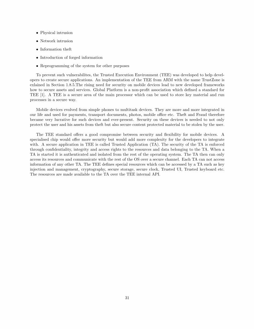
To prevent such vulnerabilites, the Trusted Execution Environment (TEE) was developed to help devel-opers to create secure applications. An implementation of the TEE from ARM with the name TrustZone isexlained in Section 1.8.5.The rising need for security on mobile devices lead to new developed frameworkshow to secure assets and services. Global Platform is a non-profit association which defined a standard forTEE [1]. A TEE is a secure area of the main processor which can be used to store key material and runprocesses in a secure way.
Mobile devices evolved from simple phones to multitask devices. They are more and more integrated inour life and used for payments, transport documents, photos, mobile office etc. Theft and Fraud thereforebecame very lucrative for such devices and ever-present. Security on these devices is needed to not onlyprotect the user and his assets from theft but also secure content protected material to be stolen by the user.
The TEE standard offers a good compromise between security and flexibility for mobile devices. Aspecialised chip would offer more security but would add more complexity for the developers to integratewith. A secure application in TEE is called Trusted Application (TA). The security of the TA is enforcedthrough confidentiality, integrity and access rights to the resources and data belonging to the TA. When aTA is started it is authenticated and isolated from the rest of the operating system. The TA then can onlyaccess its resources and communicate with the rest of the OS over a secure channel. Each TA can not accessinformation of any other TA. The TEE defines special resources which can be accessed by a TA such as keyinjection and management, cryptography, secure storage, secure clock, Trusted UI, Trusted keyboard etc.The resources are made available to the TA over the TEE internal API.
31
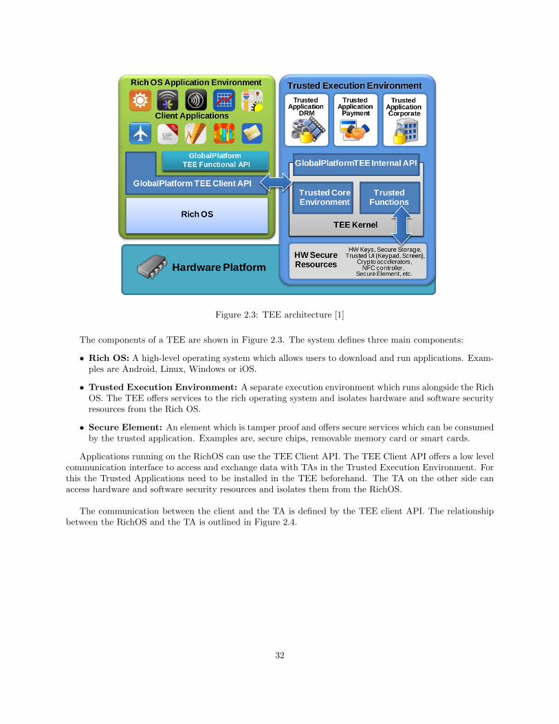
Figure 2.3: TEE architecture [1]
The components of a TEE are shown in Figure 2.3. The system defines three main components:
• Rich OS: A high-level operating system which allows users to download and run applications. Exam-ples are Android, Linux, Windows or iOS.
• Trusted Execution Environment: A separate execution environment which runs alongside the RichOS. The TEE offers services to the rich operating system and isolates hardware and software securityresources from the Rich OS.
• Secure Element: An element which is tamper proof and offers secure services which can be consumedby the trusted application. Examples are, secure chips, removable memory card or smart cards.
Applications running on the RichOS can use the TEE Client API. The TEE Client API offers a low levelcommunication interface to access and exchange data with TAs in the Trusted Execution Environment. Forthis the Trusted Applications need to be installed in the TEE beforehand. The TA on the other side canaccess hardware and software security resources and isolates them from the RichOS.
The communication between the client and the TA is defined by the TEE client API. The relationshipbetween the RichOS and the TA is outlined in Figure 2.4.
32
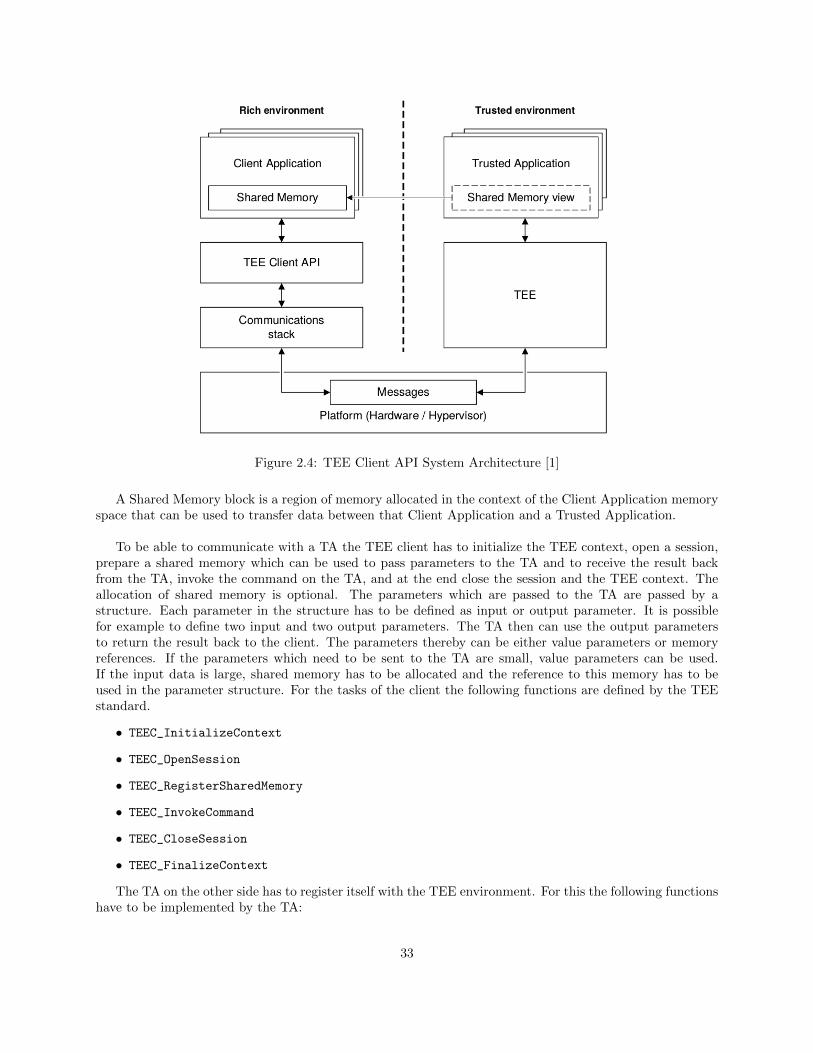
Figure 2.4: TEE Client API System Architecture [1]
A Shared Memory block is a region of memory allocated in the context of the Client Application memoryspace that can be used to transfer data between that Client Application and a Trusted Application.
To be able to communicate with a TA the TEE client has to initialize the TEE context, open a session,prepare a shared memory which can be used to pass parameters to the TA and to receive the result backfrom the TA, invoke the command on the TA, and at the end close the session and the TEE context. Theallocation of shared memory is optional. The parameters which are passed to the TA are passed by astructure. Each parameter in the structure has to be defined as input or output parameter. It is possiblefor example to define two input and two output parameters. The TA then can use the output parametersto return the result back to the client. The parameters thereby can be either value parameters or memoryreferences. If the parameters which need to be sent to the TA are small, value parameters can be used.If the input data is large, shared memory has to be allocated and the reference to this memory has to beused in the parameter structure. For the tasks of the client the following functions are defined by the TEEstandard.
• TEEC_InitializeContext
• TEEC_OpenSession
• TEEC_RegisterSharedMemory
• TEEC_InvokeCommand
• TEEC_CloseSession
• TEEC_FinalizeContext
The TA on the other side has to register itself with the TEE environment. For this the following functionshave to be implemented by the TA:
33
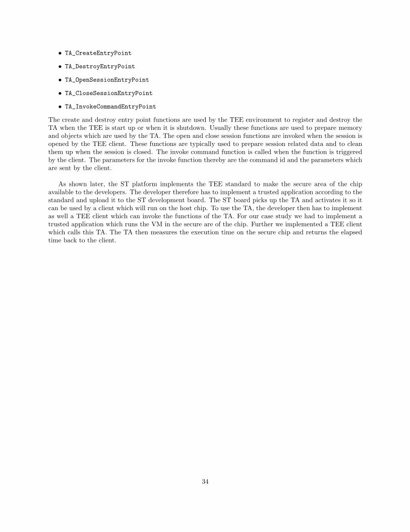
• TA_CreateEntryPoint
• TA_DestroyEntryPoint
• TA_OpenSessionEntryPoint
• TA_CloseSessionEntryPoint
• TA_InvokeCommandEntryPoint
The create and destroy entry point functions are used by the TEE environment to register and destroy theTA when the TEE is start up or when it is shutdown. Usually these functions are used to prepare memoryand objects which are used by the TA. The open and close session functions are invoked when the session isopened by the TEE client. These functions are typically used to prepare session related data and to cleanthem up when the session is closed. The invoke command function is called when the function is triggeredby the client. The parameters for the invoke function thereby are the command id and the parameters whichare sent by the client.
As shown later, the ST platform implements the TEE standard to make the secure area of the chipavailable to the developers. The developer therefore has to implement a trusted application according to thestandard and upload it to the ST development board. The ST board picks up the TA and activates it so itcan be used by a client which will run on the host chip. To use the TA, the developer then has to implementas well a TEE client which can invoke the functions of the TA. For our case study we had to implement atrusted application which runs the VM in the secure are of the chip. Further we implemented a TEE clientwhich calls this TA. The TA then measures the execution time on the secure chip and returns the elapsedtime back to the client.
34
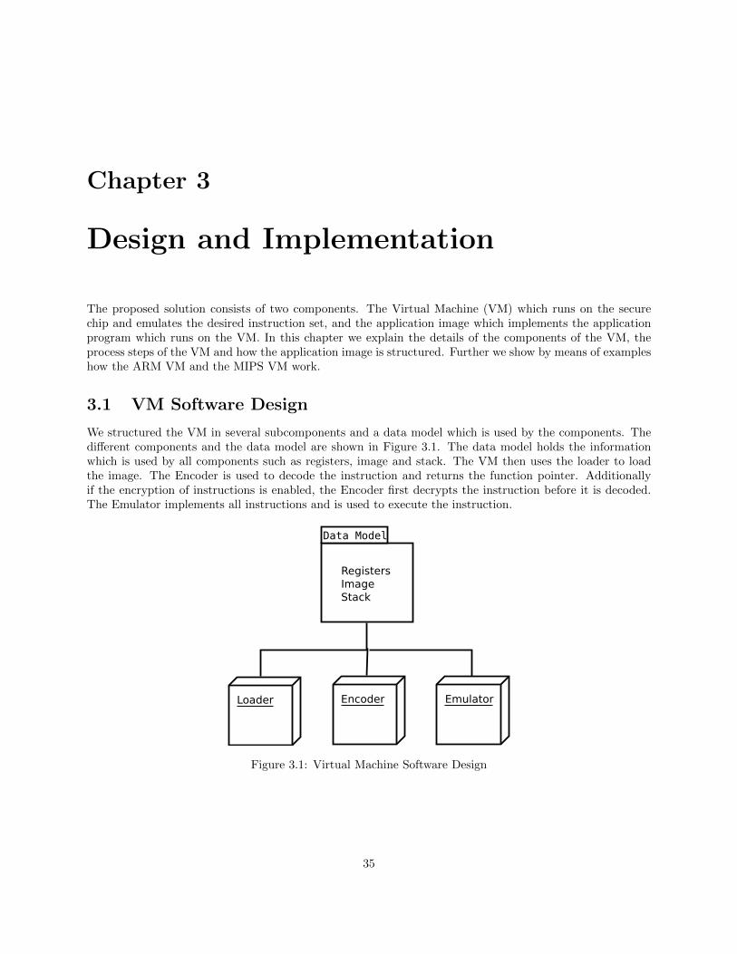
Chapter 3
Design and Implementation
The proposed solution consists of two components. The Virtual Machine (VM) which runs on the securechip and emulates the desired instruction set, and the application image which implements the applicationprogram which runs on the VM. In this chapter we explain the details of the components of the VM, theprocess steps of the VM and how the application image is structured. Further we show by means of exampleshow the ARM VM and the MIPS VM work.
3.1 VM Software Design
We structured the VM in several subcomponents and a data model which is used by the components. Thedifferent components and the data model are shown in Figure 3.1. The data model holds the informationwhich is used by all components such as registers, image and stack. The VM then uses the loader to loadthe image. The Encoder is used to decode the instruction and returns the function pointer. Additionallyif the encryption of instructions is enabled, the Encoder first decrypts the instruction before it is decoded.The Emulator implements all instructions and is used to execute the instruction.
Figure 3.1: Virtual Machine Software Design
35
3.1.1 VM Data Model
The Data Model is implemented by means of a struct, as presented in Listing 3.1, which holds the informationwhich are used by the VM and all subcomponents. The model is initialized once at the beginning and apointer to the model is passed to the different subcomponents. The application image and the stack use thesame array. The size of this array is statically initialized and needs to be adjusted so that the whole imagefits in the array and that enough space is free for the stack. When the stack is filled, it is checked that itdoes not overflow in the application image space. If this happens an error is raised and the application VMexits with an error. For our VM we used an array of 4096 bytes which was big enough for our experiments.The amount of registers depends on the Instruction Set Architecture (ISA). For ARM only 16 registers areallocated and for MIPS 20 registers.
typedef union
{
uint8_t bytes [MEMSIZEBYTES];
uint16_t hwords[MEMSIZEHWORDS];
uint32_t words [MEMSIZEWORDS];
} memory_t;
typedef struct {
/* vm data model */
uint32_t insn; /* current instruction */
uint32_t REG [MAXREG]; /* registers */
uint32_t PC; /* program counter */
memory_t img; /* image data and stack */
/* image information */
uint32_t code_entry;
uint32_t code_end;
uint32_t data_end;
uint32_t img_size;
} context_t;
Listing 3.1: VM Data Model Structure
3.1.2 VM Image Loader
The Loader is responsible for loading the application image into the data model and initializing the registersand program counter. For our experiments, the loader includes a header file which holds an array with theapplication image. From the application image the first three bytes hold the information where the codesection section ends, where the data section ends and where the first instruction is found. This informationis stored in the data model. After the offset is read from the image, the rest of the image is loaded into theimage array of the data model. Afterwards the registers are prepared and the program counter is set to theentry point. And excerpt of the code is shown in Listing 3.2. Depending on which instruction set is used,different registers have to be set.
/* pointer to data model */
context_t *ctx;
/* example application image from header file */
int img_size = 512;
static const unsigned char img[512] = {0x30,0x00,0x00,...,0x01};
/* read offsets */
36
memcpy (&ctx->code_end, img[0], 4);
memcpy (&ctx->img_size, img[4], 4);
memcpy (&ctx->code_entry, img[8], 4);
/* load image after offsets */
memcpy (&ctx->img.bytes[0], &img[12], img_size - 12);
/* set registers (stack pointer, frame pointer, program counter) */
ctx->REG[SP] = sizeof(ctx->img.bytes);
ctx->REG[FP] = sizeof(ctx->img.bytes);
ctx->PC = ctx->code_entry;
Listing 3.2: VM Loader Excerpt
3.1.3 VM Encoder
The Encoder takes as input the data model. The VM has to make sure that in the data model the currentinstruction is stored in the insn variable of the data model. If encryption of instructions is enabled, theencoder then first decrypts the instruction with a hardcoded key. After decryption the Encoder uses a lookuptable to check which instruction has to executed by the Emulator. The lookup table has pointers to functionswhich are implemented in the Emulator. For ARM the lookup table uses bits 15 to 6 of the instruction to getthe correct instruction. If the Encoder can not find a function in the lookup table for the current instruction,the current instruction uses more bits than 15 to 6 for the encoding. For example the NOP instruction needsall 16 bits for full identification. Therefore if the Encoder can not identify the instruction with help of thelookup table, a small switch block is used to identify the remaining instructions. As shown in Listing 3.3,the Loader returns the function pointer which is used by the VM to execute the correct instruction.
/* pointer to data model */
context_t *ctx;
/* lookup table with pointers to functions */
typedef int (*insn_func)(context_t *);
insn_func table[1024] = {[0x0000]=&arm_movs_reg,[0x0001]=&arm_lsls_imm,
..,[0x039f]=&arm_b_t2};
/* use bits 15 to 6 and check in lookup table */
uint16_t bits15_6 = ctx->insn >> 6;
insn_func f = table[bits15_6];
if(f != NULL){
return
}
/* if not in lookup table check here */
switch((uint16_t)ctx->insn){
case ARM_NOP:
return &arm_nop(ctx);
...
}
Listing 3.3: VM Encoder Excerpt
37
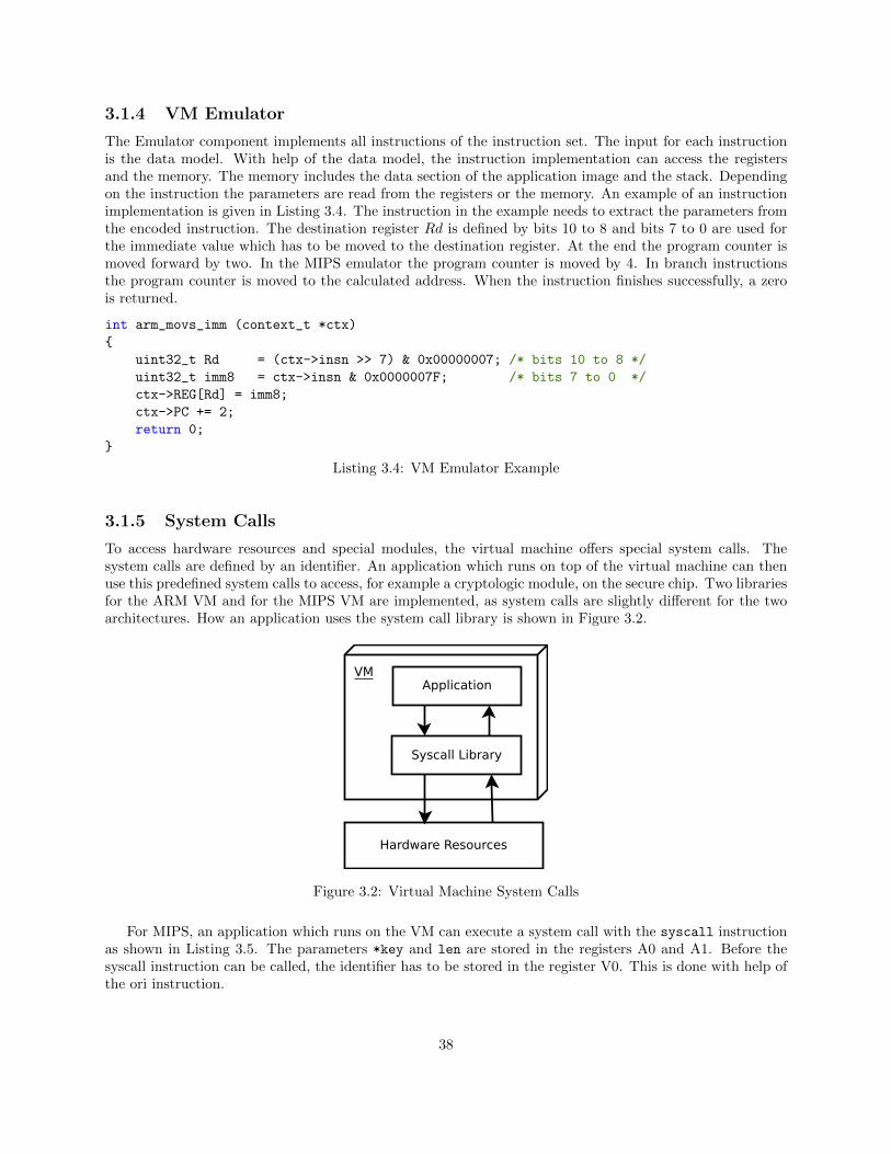
3.1.4 VM Emulator
The Emulator component implements all instructions of the instruction set. The input for each instructionis the data model. With help of the data model, the instruction implementation can access the registersand the memory. The memory includes the data section of the application image and the stack. Dependingon the instruction the parameters are read from the registers or the memory. An example of an instructionimplementation is given in Listing 3.4. The instruction in the example needs to extract the parameters fromthe encoded instruction. The destination register Rd is defined by bits 10 to 8 and bits 7 to 0 are used forthe immediate value which has to be moved to the destination register. At the end the program counter ismoved forward by two. In the MIPS emulator the program counter is moved by 4. In branch instructionsthe program counter is moved to the calculated address. When the instruction finishes successfully, a zerois returned.
int arm_movs_imm (context_t *ctx)
{
uint32_t Rd = (ctx->insn >> 7) & 0x00000007; /* bits 10 to 8 */
uint32_t imm8 = ctx->insn & 0x0000007F; /* bits 7 to 0 */
ctx->REG[Rd] = imm8;
ctx->PC += 2;
return 0;
}
Listing 3.4: VM Emulator Example
3.1.5 System Calls
To access hardware resources and special modules, the virtual machine offers special system calls. Thesystem calls are defined by an identifier. An application which runs on top of the virtual machine can thenuse this predefined system calls to access, for example a cryptologic module, on the secure chip. Two librariesfor the ARM VM and for the MIPS VM are implemented, as system calls are slightly different for the twoarchitectures. How an application uses the system call library is shown in Figure 3.2.
Figure 3.2: Virtual Machine System Calls
For MIPS, an application which runs on the VM can execute a system call with the syscall instructionas shown in Listing 3.5. The parameters *key and len are stored in the registers A0 and A1. Before thesyscall instruction can be called, the identifier has to be stored in the register V0. This is done with help ofthe ori instruction.
38
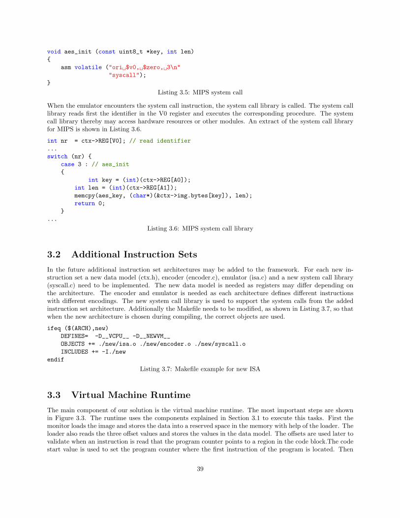
void aes_init (const uint8_t *key, int len)
{
asm volatile ("ori $v0, $zero, 3\n"
"syscall");
}
Listing 3.5: MIPS system call
When the emulator encounters the system call instruction, the system call library is called. The system calllibrary reads first the identifier in the V0 register and executes the corresponding procedure. The systemcall library thereby may access hardware resources or other modules. An extract of the system call libraryfor MIPS is shown in Listing 3.6.
int nr = ctx->REG[V0]; // read identifier
...
switch (nr) {
case 3 : // aes_init
{
int key = (int)(ctx->REG[A0]);
int len = (int)(ctx->REG[A1]);
memcpy(aes_key, (char*)(&ctx->img.bytes[key]), len);
return 0;
}
...
Listing 3.6: MIPS system call library
3.2 Additional Instruction Sets
In the future additional instruction set architectures may be added to the framework. For each new in-struction set a new data model (ctx.h), encoder (encoder.c), emulator (isa.c) and a new system call library(syscall.c) need to be implemented. The new data model is needed as registers may differ depending onthe architecture. The encoder and emulator is needed as each architecture defines different instructionswith different encodings. The new system call library is used to support the system calls from the addedinstruction set architecture. Additionally the Makefile needs to be modified, as shown in Listing 3.7, so thatwhen the new architecture is chosen during compiling, the correct objects are used.
ifeq ($(ARCH),new)
DEFINES= -D__VCPU__ -D__NEWVM__
OBJECTS += ./new/isa.o ./new/encoder.o ./new/syscall.o
INCLUDES += -I./new
endif
Listing 3.7: Makefile example for new ISA
3.3 Virtual Machine Runtime
The main component of our solution is the virtual machine runtime. The most important steps are shownin Figure 3.3. The runtime uses the components explained in Section 3.1 to execute this tasks. First themonitor loads the image and stores the data into a reserved space in the memory with help of the loader. Theloader also reads the three offset values and stores the values in the data model. The offsets are used later tovalidate when an instruction is read that the program counter points to a region in the code block.The codestart value is used to set the program counter where the first instruction of the program is located. Then
39
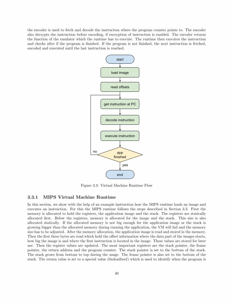
the encoder is used to fetch and decode the instruction where the program counter points to. The encoderalso decrypts the instruction before encoding, if encryption of instruction is enabled. The encoder returnsthe function of the emulator which the runtime has to execute. The runtime then executes the instructionand checks after if the program is finished. If the program is not finished, the next instruction is fetched,encoded and executed until the last instruction is reached.
Figure 3.3: Virtual Machine Runtime Flow
3.3.1 MIPS Virtual Machine Runtime
In this section, we show with the help of an example instruction how the MIPS runtime loads an image andexecutes an instruction. For this the MIPS runtime follows the steps described in Section 3.3. First thememory is allocated to hold the registers, the application image and the stack. The registers are staticallyallocated first. Below the registers, memory is allocated for the image and the stack. This size is alsoallocated statically. If the allocated memory is not big enough for the application image or the stack isgrowing bigger than the allocated memory during running the application, the VM will fail and the memorysize has to be adjusted. After the memory allocation, the application image is read and stored in the memory.Then the first three bytes are read which hold the offset information where the data part of the images starts,how big the image is and where the first instruction is located in the image. These values are stored for lateruse. Then the register values are updated. The most important registers are the stack pointer, the framepointer, the return address and the program counter. The stack pointer is set to the bottom of the stack.The stack grows from bottom to top during the usage. The frame pointer is also set to the bottom of thestack. The return value is set to a special value (0xdeadbeef) which is used to identify when the program is
40
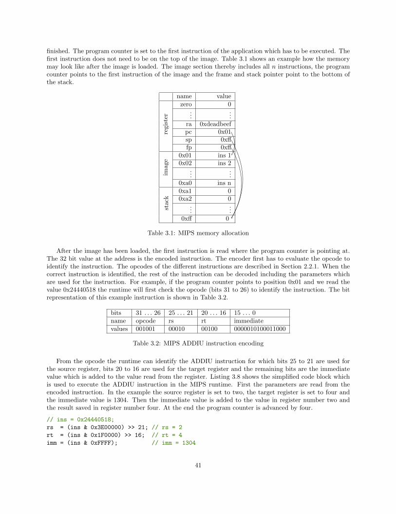
finished. The program counter is set to the first instruction of the application which has to be executed. Thefirst instruction does not need to be on the top of the image. Table 3.1 shows an example how the memorymay look like after the image is loaded. The image section thereby includes all n instructions, the programcounter points to the first instruction of the image and the frame and stack pointer point to the bottom ofthe stack.
name value
regis
ter
zero 0...
...ra 0xdeadbeefpc 0x01sp 0xfffp 0xff
image
0x01 ins 10x02 ins 2
......
0xa0 ins n
stac
k
0xa1 00xa2 0
......
0xff 0
Table 3.1: MIPS memory allocation
After the image has been loaded, the first instruction is read where the program counter is pointing at.The 32 bit value at the address is the encoded instruction. The encoder first has to evaluate the opcode toidentify the instruction. The opcodes of the different instructions are described in Section 2.2.1. When thecorrect instruction is identified, the rest of the instruction can be decoded including the parameters whichare used for the instruction. For example, if the program counter points to position 0x01 and we read thevalue 0x24440518 the runtime will first check the opcode (bits 31 to 26) to identify the instruction. The bitrepresentation of this example instruction is shown in Table 3.2.
bits 31 . . . 26 25 . . . 21 20 . . . 16 15 . . . 0name opcode rs rt immediatevalues 001001 00010 00100 0000010100011000
Table 3.2: MIPS ADDIU instruction encoding
From the opcode the runtime can identify the ADDIU instruction for which bits 25 to 21 are used forthe source register, bits 20 to 16 are used for the target register and the remaining bits are the immediatevalue which is added to the value read from the register. Listing 3.8 shows the simplified code block whichis used to execute the ADDIU instruction in the MIPS runtime. First the parameters are read from theencoded instruction. In the example the source register is set to two, the target register is set to four andthe immediate value is 1304. Then the immediate value is added to the value in register number two andthe result saved in register number four. At the end the program counter is advanced by four.
// ins = 0x24440518;
rs = (ins & 0x3E00000) >> 21; // rs = 2
rt = (ins & 0x1F0000) >> 16; // rt = 4
imm = (ins & 0xFFFF); // imm = 1304
41
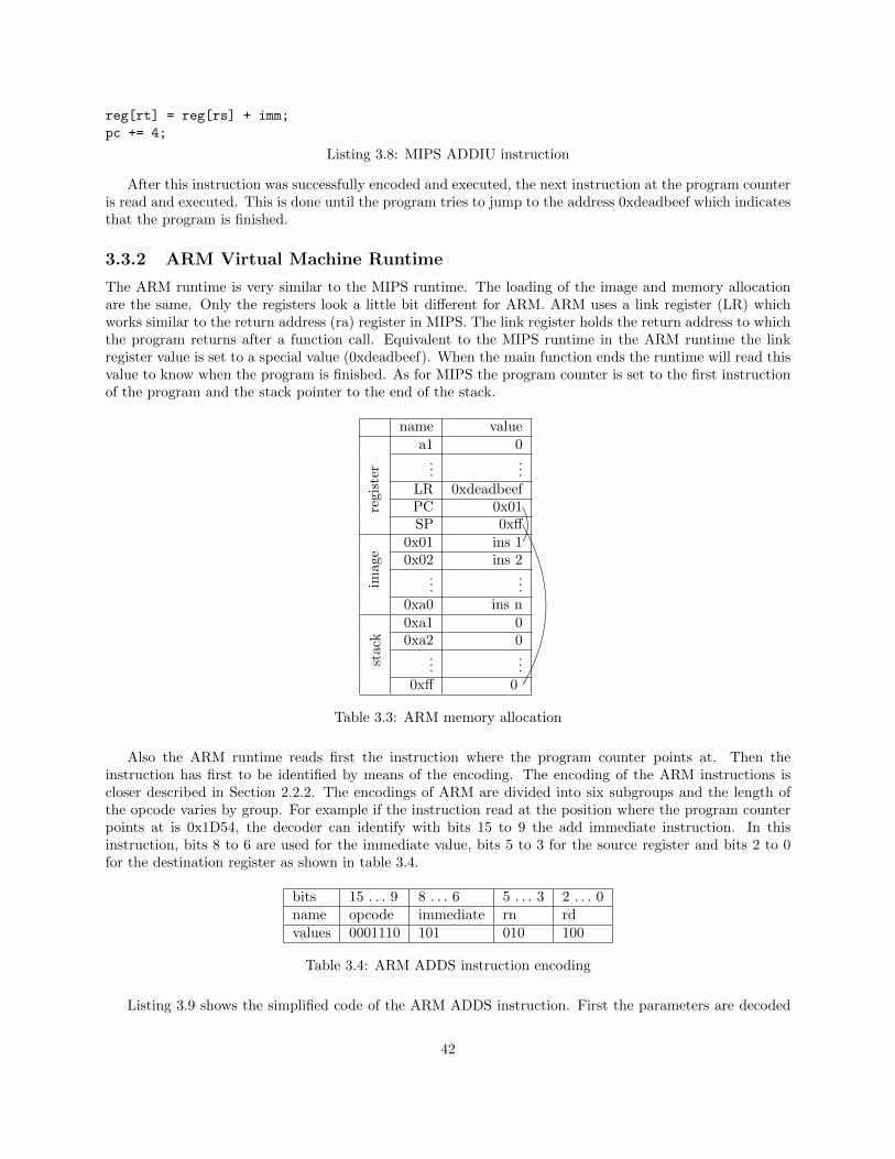
reg[rt] = reg[rs] + imm;
pc += 4;
Listing 3.8: MIPS ADDIU instruction
After this instruction was successfully encoded and executed, the next instruction at the program counteris read and executed. This is done until the program tries to jump to the address 0xdeadbeef which indicatesthat the program is finished.
3.3.2 ARM Virtual Machine Runtime
The ARM runtime is very similar to the MIPS runtime. The loading of the image and memory allocationare the same. Only the registers look a little bit different for ARM. ARM uses a link register (LR) whichworks similar to the return address (ra) register in MIPS. The link register holds the return address to whichthe program returns after a function call. Equivalent to the MIPS runtime in the ARM runtime the linkregister value is set to a special value (0xdeadbeef). When the main function ends the runtime will read thisvalue to know when the program is finished. As for MIPS the program counter is set to the first instructionof the program and the stack pointer to the end of the stack.
name value
regi
ster
a1 0...
...LR 0xdeadbeefPC 0x01SP 0xff
imag
e
0x01 ins 10x02 ins 2
......
0xa0 ins n
stac
k
0xa1 00xa2 0
......
0xff 0
Table 3.3: ARM memory allocation
Also the ARM runtime reads first the instruction where the program counter points at. Then theinstruction has first to be identified by means of the encoding. The encoding of the ARM instructions iscloser described in Section 2.2.2. The encodings of ARM are divided into six subgroups and the length ofthe opcode varies by group. For example if the instruction read at the position where the program counterpoints at is 0x1D54, the decoder can identify with bits 15 to 9 the add immediate instruction. In thisinstruction, bits 8 to 6 are used for the immediate value, bits 5 to 3 for the source register and bits 2 to 0for the destination register as shown in table 3.4.
bits 15 . . . 9 8 . . . 6 5 . . . 3 2 . . . 0name opcode immediate rn rdvalues 0001110 101 010 100
Table 3.4: ARM ADDS instruction encoding
Listing 3.9 shows the simplified code of the ARM ADDS instruction. First the parameters are decoded
42
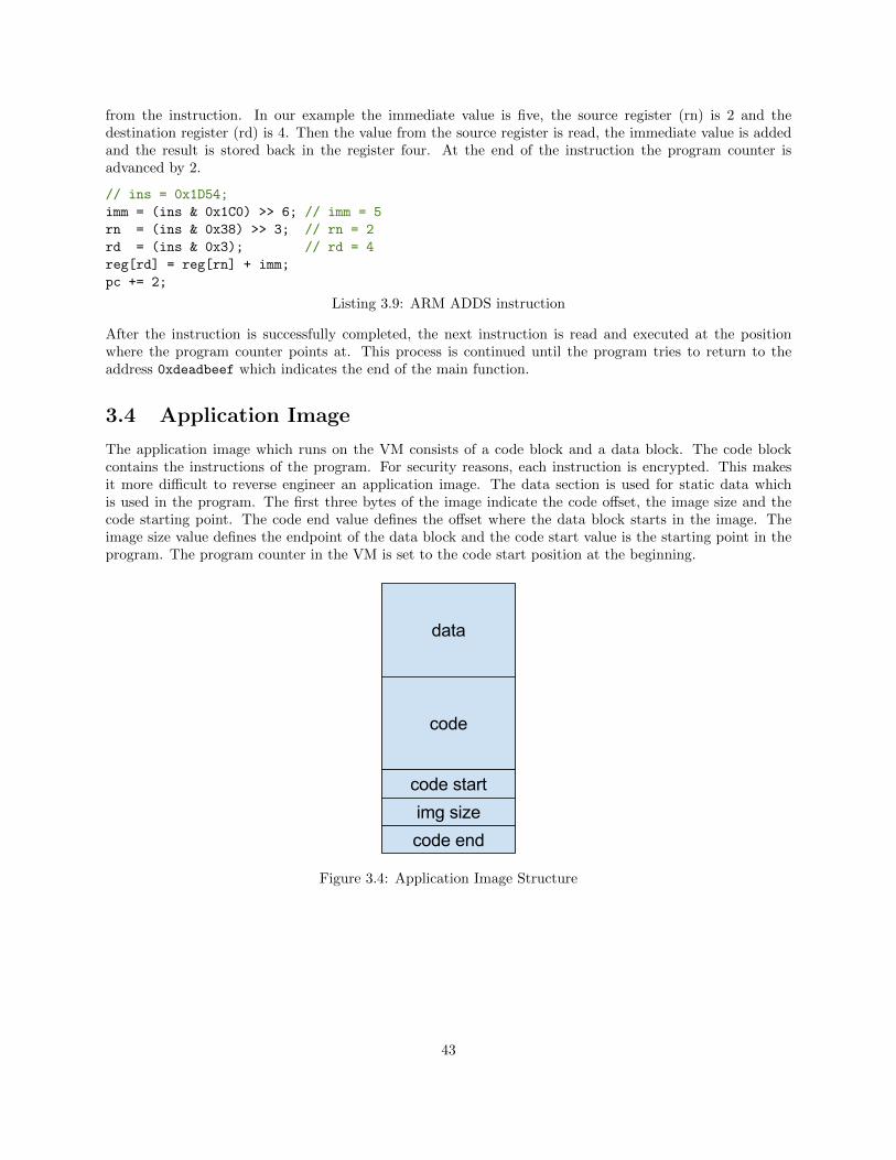
from the instruction. In our example the immediate value is five, the source register (rn) is 2 and thedestination register (rd) is 4. Then the value from the source register is read, the immediate value is addedand the result is stored back in the register four. At the end of the instruction the program counter isadvanced by 2.
// ins = 0x1D54;
imm = (ins & 0x1C0) >> 6; // imm = 5
rn = (ins & 0x38) >> 3; // rn = 2
rd = (ins & 0x3); // rd = 4
reg[rd] = reg[rn] + imm;
pc += 2;
Listing 3.9: ARM ADDS instruction
After the instruction is successfully completed, the next instruction is read and executed at the positionwhere the program counter points at. This process is continued until the program tries to return to theaddress 0xdeadbeef which indicates the end of the main function.
3.4 Application Image
The application image which runs on the VM consists of a code block and a data block. The code blockcontains the instructions of the program. For security reasons, each instruction is encrypted. This makesit more difficult to reverse engineer an application image. The data section is used for static data whichis used in the program. The first three bytes of the image indicate the code offset, the image size and thecode starting point. The code end value defines the offset where the data block starts in the image. Theimage size value defines the endpoint of the data block and the code start value is the starting point in theprogram. The program counter in the VM is set to the code start position at the beginning.
Figure 3.4: Application Image Structure
43
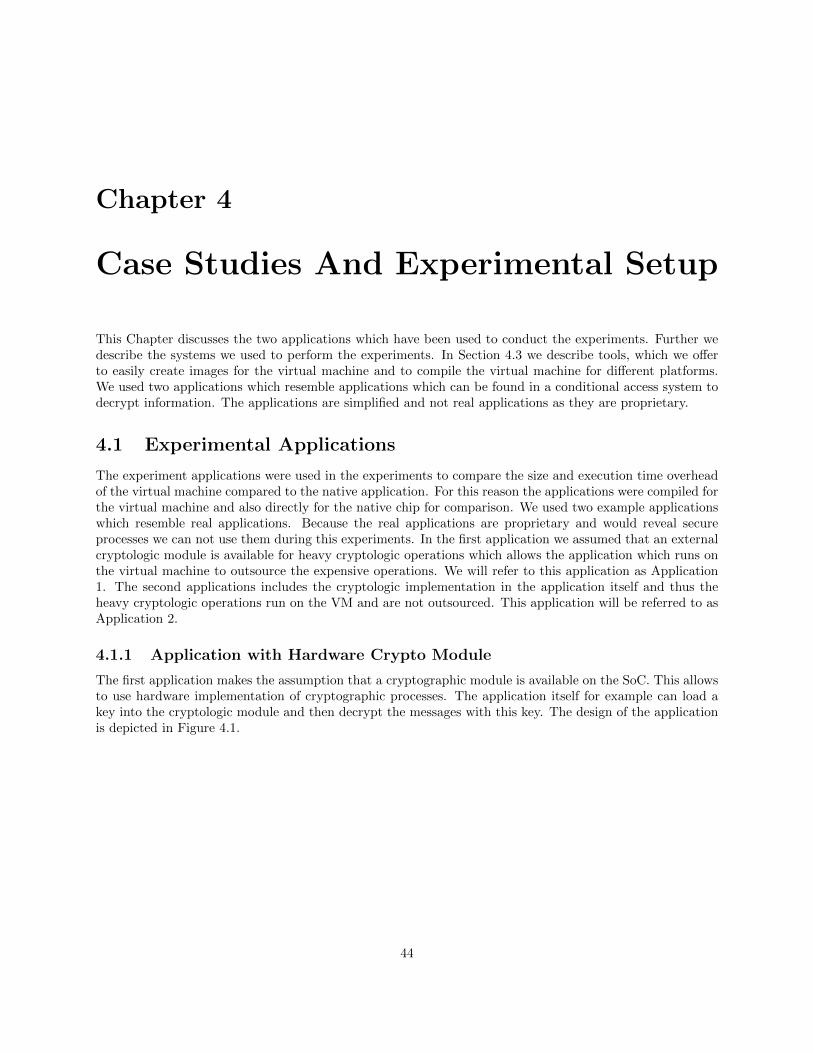
Chapter 4
Case Studies And Experimental Setup
This Chapter discusses the two applications which have been used to conduct the experiments. Further wedescribe the systems we used to perform the experiments. In Section 4.3 we describe tools, which we offerto easily create images for the virtual machine and to compile the virtual machine for different platforms.We used two applications which resemble applications which can be found in a conditional access system todecrypt information. The applications are simplified and not real applications as they are proprietary.
4.1 Experimental Applications
The experiment applications were used in the experiments to compare the size and execution time overheadof the virtual machine compared to the native application. For this reason the applications were compiled forthe virtual machine and also directly for the native chip for comparison. We used two example applicationswhich resemble real applications. Because the real applications are proprietary and would reveal secureprocesses we can not use them during this experiments. In the first application we assumed that an externalcryptologic module is available for heavy cryptologic operations which allows the application which runs onthe virtual machine to outsource the expensive operations. We will refer to this application as Application1. The second applications includes the cryptologic implementation in the application itself and thus theheavy cryptologic operations run on the VM and are not outsourced. This application will be referred to asApplication 2.
4.1.1 Application with Hardware Crypto Module
The first application makes the assumption that a cryptographic module is available on the SoC. This allowsto use hardware implementation of cryptographic processes. The application itself for example can load akey into the cryptologic module and then decrypt the messages with this key. The design of the applicationis depicted in Figure 4.1.
44
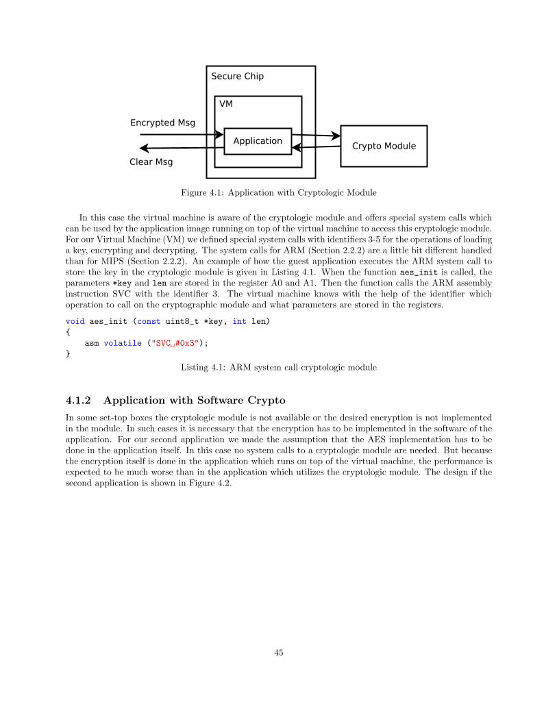
Figure 4.1: Application with Cryptologic Module
In this case the virtual machine is aware of the cryptologic module and offers special system calls whichcan be used by the application image running on top of the virtual machine to access this cryptologic module.For our Virtual Machine (VM) we defined special system calls with identifiers 3-5 for the operations of loadinga key, encrypting and decrypting. The system calls for ARM (Section 2.2.2) are a little bit different handledthan for MIPS (Section 2.2.2). An example of how the guest application executes the ARM system call tostore the key in the cryptologic module is given in Listing 4.1. When the function aes_init is called, theparameters *key and len are stored in the register A0 and A1. Then the function calls the ARM assemblyinstruction SVC with the identifier 3. The virtual machine knows with the help of the identifier whichoperation to call on the cryptographic module and what parameters are stored in the registers.
void aes_init (const uint8_t *key, int len)
{
asm volatile ("SVC #0x3");
}
Listing 4.1: ARM system call cryptologic module
4.1.2 Application with Software Crypto
In some set-top boxes the cryptologic module is not available or the desired encryption is not implementedin the module. In such cases it is necessary that the encryption has to be implemented in the software of theapplication. For our second application we made the assumption that the AES implementation has to bedone in the application itself. In this case no system calls to a cryptologic module are needed. But becausethe encryption itself is done in the application which runs on top of the virtual machine, the performance isexpected to be much worse than in the application which utilizes the cryptologic module. The design if thesecond application is shown in Figure 4.2.
45
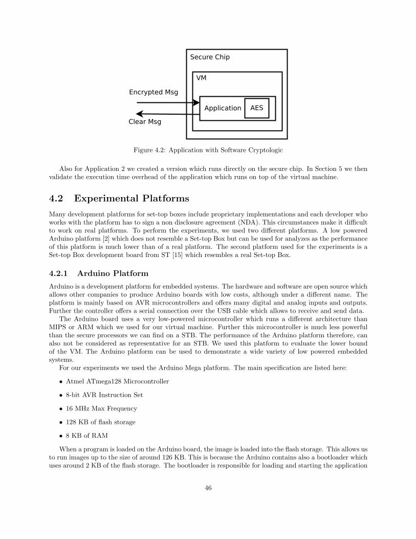
Figure 4.2: Application with Software Cryptologic
Also for Application 2 we created a version which runs directly on the secure chip. In Section 5 we thenvalidate the execution time overhead of the application which runs on top of the virtual machine.
4.2 Experimental Platforms
Many development platforms for set-top boxes include proprietary implementations and each developer whoworks with the platform has to sign a non disclosure agreement (NDA). This circumstances make it difficultto work on real platforms. To perform the experiments, we used two different platforms. A low poweredArduino platform [2] which does not resemble a Set-top Box but can be used for analyzes as the performanceof this platform is much lower than of a real platform. The second platform used for the experiments is aSet-top Box development board from ST [15] which resembles a real Set-top Box.
4.2.1 Arduino Platform
Arduino is a development platform for embedded systems. The hardware and software are open source whichallows other companies to produce Arduino boards with low costs, although under a different name. Theplatform is mainly based on AVR microcontrollers and offers many digital and analog inputs and outputs.Further the controller offers a serial connection over the USB cable which allows to receive and send data.
The Arduino board uses a very low-powered microcontroller which runs a different architecture thanMIPS or ARM which we used for our virtual machine. Further this microcontroller is much less powerfulthan the secure processors we can find on a STB. The performance of the Arduino platform therefore, canalso not be considered as representative for an STB. We used this platform to evaluate the lower boundof the VM. The Arduino platform can be used to demonstrate a wide variety of low powered embeddedsystems.
For our experiments we used the Arduino Mega platform. The main specification are listed here:
• Atmel ATmega128 Microcontroller
• 8-bit AVR Instruction Set
• 16 MHz Max Frequency
• 128 KB of flash storage
• 8 KB of RAM
When a program is loaded on the Arduino board, the image is loaded into the flash storage. This allows usto run images up to the size of around 126 KB. This is because the Arduino contains also a bootloader whichuses around 2 KB of the flash storage. The bootloader is responsible for loading and starting the application
46
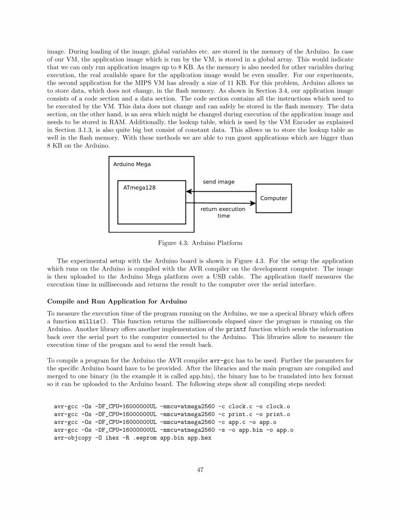
image. During loading of the image, global variables etc. are stored in the memory of the Arduino. In caseof our VM, the application image which is run by the VM, is stored in a global array. This would indicatethat we can only run application images up to 8 KB. As the memory is also needed for other variables duringexecution, the real available space for the application image would be even smaller. For our experiments,the second application for the MIPS VM has already a size of 11 KB. For this problem, Arduino allows usto store data, which does not change, in the flash memory. As shown in Section 3.4, our application imageconsists of a code section and a data section. The code section contains all the instructions which need tobe executed by the VM. This data does not change and can safely be stored in the flash memory. The datasection, on the other hand, is an area which might be changed during execution of the application image andneeds to be stored in RAM. Additionally, the lookup table, which is used by the VM Encoder as explainedin Section 3.1.3, is also quite big but consist of constant data. This allows us to store the lookup table aswell in the flash memory. With these methods we are able to run guest applications which are bigger than8 KB on the Arduino.
Figure 4.3: Arduino Platform
The experimental setup with the Arduino board is shown in Figure 4.3. For the setup the applicationwhich runs on the Arduino is compiled with the AVR compiler on the development computer. The imageis then uploaded to the Arduino Mega platform over a USB cable. The application itself measures theexecution time in milliseconds and returns the result to the computer over the serial interface.
Compile and Run Application for Arduino
To measure the execution time of the program running on the Arduino, we use a specical library which offersa function millis(). This function returns the milliseconds elapsed since the program is running on theArduino. Another library offers another implementation of the printf function which sends the informationback over the serial port to the computer connected to the Arduino. This libraries allow to measure theexecution time of the progam and to send the result back.
To compile a program for the Arduino the AVR compiler avr-gcc has to be used. Further the paramters forthe specific Arduino board have to be provided. After the libraries and the main program are compiled andmerged to one binary (in the example it is called app.bin), the binary has to be translated into hex formatso it can be uploaded to the Arduino board. The following steps show all compiling steps needed:
avr-gcc -Os -DF_CPU=16000000UL -mmcu=atmega2560 -c clock.c -o clock.o
avr-gcc -Os -DF_CPU=16000000UL -mmcu=atmega2560 -c print.c -o print.o
avr-gcc -Os -DF_CPU=16000000UL -mmcu=atmega2560 -c app.c -o app.o
avr-gcc -Os -DF_CPU=16000000UL -mmcu=atmega2560 -s -o app.bin -o app.o
avr-objcopy -O ihex -R .eeprom app.bin app.hex
47
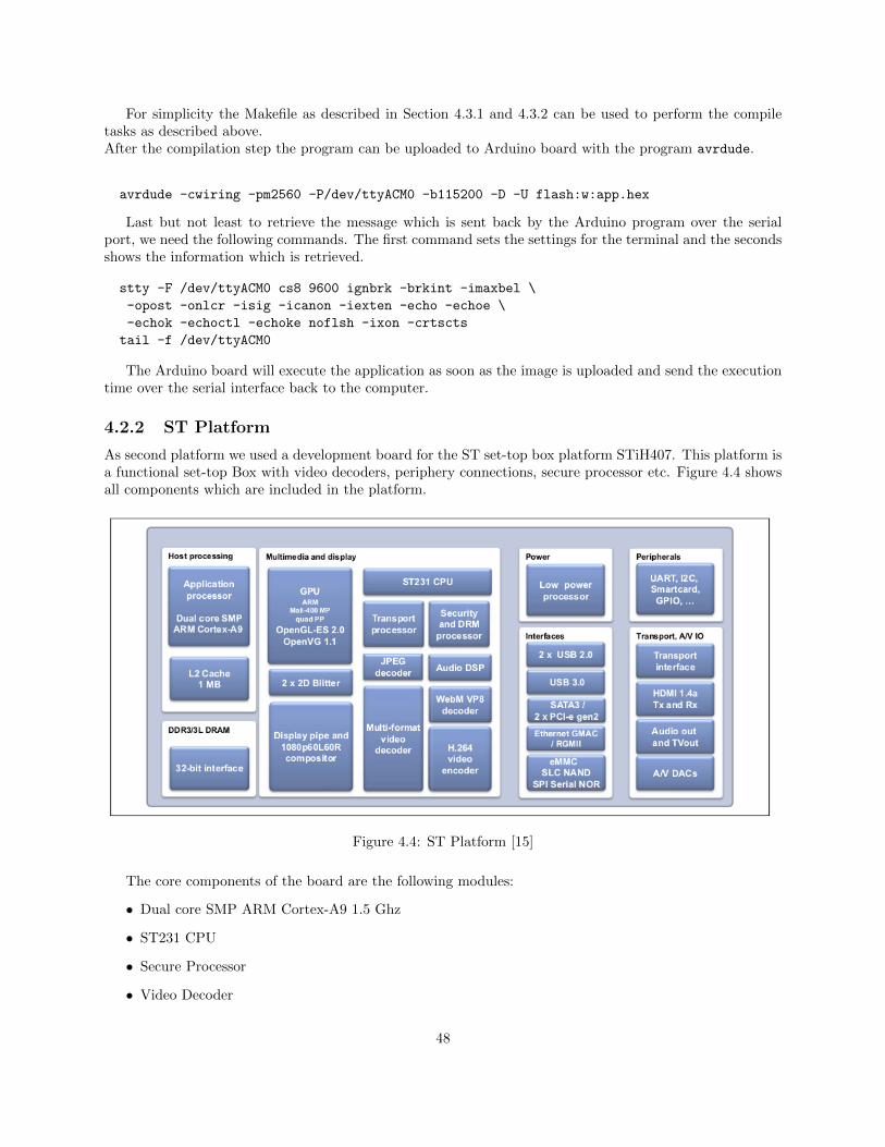
For simplicity the Makefile as described in Section 4.3.1 and 4.3.2 can be used to perform the compiletasks as described above.After the compilation step the program can be uploaded to Arduino board with the program avrdude.
avrdude -cwiring -pm2560 -P/dev/ttyACM0 -b115200 -D -U flash:w:app.hex
Last but not least to retrieve the message which is sent back by the Arduino program over the serialport, we need the following commands. The first command sets the settings for the terminal and the secondsshows the information which is retrieved.
stty -F /dev/ttyACM0 cs8 9600 ignbrk -brkint -imaxbel \
-opost -onlcr -isig -icanon -iexten -echo -echoe \
-echok -echoctl -echoke noflsh -ixon -crtscts
tail -f /dev/ttyACM0
The Arduino board will execute the application as soon as the image is uploaded and send the executiontime over the serial interface back to the computer.
4.2.2 ST Platform
As second platform we used a development board for the ST set-top box platform STiH407. This platform isa functional set-top Box with video decoders, periphery connections, secure processor etc. Figure 4.4 showsall components which are included in the platform.
Figure 4.4: ST Platform [15]
The core components of the board are the following modules:
• Dual core SMP ARM Cortex-A9 1.5 Ghz
• ST231 CPU
• Secure Processor
• Video Decoder
48
The ST231 CPU and the secure processor are both processors of the ST200 family. The ST200 family areprocessor for the Very Long Instruction Word (VLIW) architecture.
To utilize the secure processor, ST offers an implementation of the Trusted Execution Environment(TEE) standard. This way a client has to be implemented which runs on the host ST231 CPU and aTrusted Application (TA) which can be loaded on the secure processor. The client can then call and run theTA application. The communication thereby is defined by the TEE standard as described in Section 2.4.
Compile and Run Trusted Application for ST
To be able to run the VM on ST, we need to create a trusted application and a client which calls the TAwhich runs on the secure chip. For the TA we have to compile the VM with the ST compiler. This canbe done with the Makefile and the target ST as described in Section 4.3.2. The output of the Makefile isa library which then can be integrated with the TA. The TA implements the functions according to theTEE standard as described in Section 2.4. In the invoke command function the TA then runs the VM andmeasures the execution time. The elapsed time is then sent back to the client. We offer a Makefile to createthe TA which takes VM library as parameter.
make ta VMLIB=vm.a
Additionally we have to create a firmware file which dynamically links the TA. The firmware file is usedby the ST platform to run the TA. This file again can be created with the Makefile.
make fw
Last we also have to create the client which will call the TA. The client has to create the session andinvoke the function of the TA as described in the Section 2.4. The client is compiled with the Makefile asfollow:
make ca
The output of the three Makefile commands are three files which have to be uploaded to the ST platform.The ST platform runs a special Linux version which takes care of running the trusted applications. To installthe TA we just have to copy it to the correct location on the platform.
# copy the trusted application
cp ddccbbaa-4624-4897-80dd91cce44c9c57.ta /lib/optee_st231
# copy the firmware
cd tee_firmware-stih407_gp0.elf /lib/firmware
# copy the client
cp tee_apptest /opt/local/bin
After this steps, we can run the client which runs the TA and receives the execution time back from theTA. The execution time is measured with a library offered by the ST platform which measures the time inclicks. The client outputs then the elapsed time on the console.
tee_apptest
4.3 Create Application Image and Virtual Machine
In this section we describe how the application image for the virtual machine can be created and how thevirtual machine can be compiled for different platforms. We have developed tools to simplify this process.
49
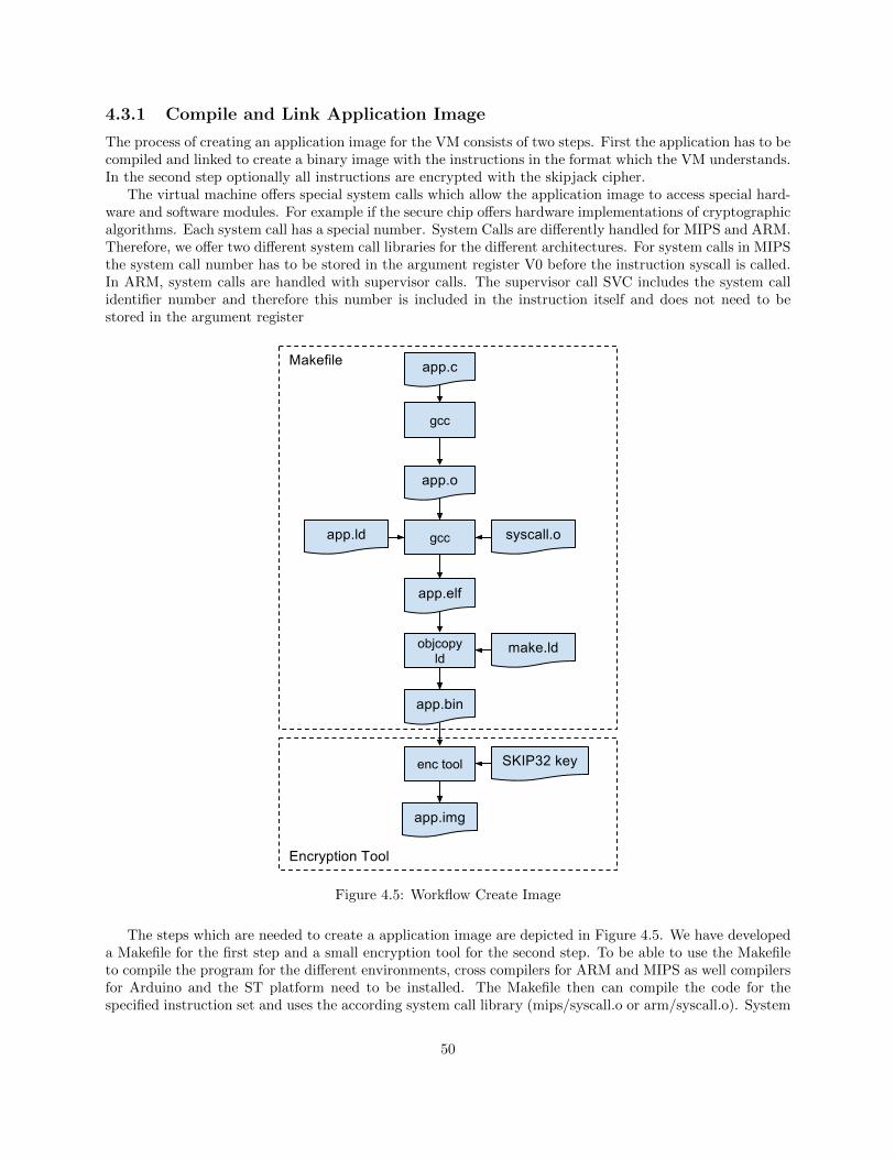
4.3.1 Compile and Link Application Image
The process of creating an application image for the VM consists of two steps. First the application has to becompiled and linked to create a binary image with the instructions in the format which the VM understands.In the second step optionally all instructions are encrypted with the skipjack cipher.
The virtual machine offers special system calls which allow the application image to access special hard-ware and software modules. For example if the secure chip offers hardware implementations of cryptographicalgorithms. Each system call has a special number. System Calls are differently handled for MIPS and ARM.Therefore, we offer two different system call libraries for the different architectures. For system calls in MIPSthe system call number has to be stored in the argument register V0 before the instruction syscall is called.In ARM, system calls are handled with supervisor calls. The supervisor call SVC includes the system callidentifier number and therefore this number is included in the instruction itself and does not need to bestored in the argument register
Figure 4.5: Workflow Create Image
The steps which are needed to create a application image are depicted in Figure 4.5. We have developeda Makefile for the first step and a small encryption tool for the second step. To be able to use the Makefileto compile the program for the different environments, cross compilers for ARM and MIPS as well compilersfor Arduino and the ST platform need to be installed. The Makefile then can compile the code for thespecified instruction set and uses the according system call library (mips/syscall.o or arm/syscall.o). System
50
calls are differently handled for ARM and MIPS and therefore needs different libraries. Further we also offera AES library with a software AES implementation which can be used by the application program. TheAES library can be added with a parameter when running the Makefile. The Makefile can also be used togenerate the native executables for x86 systems, Arduino Mega or the ST platform. Examples of how to usethe Makefile are as follow:
# build app for ARM VM
make ARCH=arm app.bin
# build app for MIPS VM
make ARCH=mips app.bin
# build app for Arduino Mega
make ARCH=mega app.bin
# build app for ST platform
make ARCH=st app.bin
# build app for x86 system
make ARCH=x86 app.bin
# build app including AES library
make ARCH=arm LIB=aes app.bin
Optionally the instructions in the images for the VM can also be encrypted for additional security. Forthe native images this step is not needed. To be able to use the encrypted images with the VM, the VMneeds to enable encryption mode. During the experiments we evaluated if the encryption of the instructionsadds significant overhead. For the encryption we have developed a tool vm-tool-enc.
# encrypt instructoins of app
vm-tool-enc -i app.bin -o app_enc.img
The images, encrypted or not, can not yet directly be used by our VM. For simplicity, the images aredirectly integrated together with the VM. That allows us to create executables of the VM which include theimages already. This way the execution of the VM on the Arduino or ST platform is much simpler. We justhave to run the executable which includes the VM and the application image. To be able to integrate theapplication image with the VM we have to create a header file which includes an array with the data of theapplication image. For this we created a tool vm-tool-header. The resulting header files can be used whenthe VM is compiled.
# create header file from application image
vm-tool-header -i app.bin -o app.h
# create header file from encrypted application image
vm-tool-header -i app_end.img -o app_enc.h
4.3.2 Compile Virtual Machine
After the image is compiled for the VM, we can compiler the VM which will include the images. For thisstep we also developed a Makefile. Again this Makefile can be used to compile the VM for the Arduino,for the ST platform, or an x86 system. Also here we need the necessary compilers pre installed. For theMakefile we need to specify which architecture the image uses, MIPS or ARM, if the image is encrypted ornot, and for which target platform the VM needs to be compiled. Different examples are shown here:
# create ARM VM for ST with application image
make ARCH=arm ENC=0 TARGET=st IMG=app.h
# create ARM VM for Arduino with application image
make ARCH=arm ENC=0 TARGET=mega IMG=app.h
# create ARM VM for x86 with application image
51
make ARCH=arm ENC=0 TARGET=x86 IMG=app.h
# create MIPS VM for ST with application image
make ARCH=mips ENC=0 TARGET=x86 IMG=app.h
# create MIPS VM for ST with encypted application image
make ARCH=mips ENC=1 TARGET=x86 IMG=app.h
The output of the Makefile with x86 target is an executable which can be run on the computer. For theArduino target, the output is a hex file which can be uploaded to the Arduino board. For ST, the outputis a library which has to be integrated with a trusted application which runs on the ST platform. How theArduino file is uploaded and executed is described in Section 4.2.1. How the ST library is used with the STplatform is described in Section 4.2.2.
52
Chapter 5
Experiments and Results
In this chapter, we discuss the experiments and the results. In the first experiment we evaluate the code sizeoverhead which the virtual machine adds compared to the native application. In the second experiment, wecompare the execution time slowdown of running the application natively on the secure chip or on top ofthe virtual machine.
5.1 Code Size Overhead of VM
For the size overhead analysis we compiled the example applications, described in Section 4, for differentplatforms. Further we compiled the application once for the ARM virtual machine and once for the MIPSvirtual machine. Also, we distinguished between encryption mode on and off in the VM. Encryption modemeans that each instruction of the application running on the VM is encrypted with a hardcoded key inthe VM. Before the VM can execute the instruction it needs to decrypt the instruction. This adds anotherlayer of security but also increases the VM size as the decryption algorithm needs to be included in the VM.For the size overhead we used four different platforms. Arduino [2], ST [15], R2 [4] and Neotion [3]. R2and Neotion are another Set-top Box (STB) platforms for which we had the compilers available but not theexecution platform.
5.1.1 Application 1
First, we compare the code size overhead of the first application for the different platforms. The results foreach platform are shown in Table 5.1 to 5.4. The numbers shown in the table are the sizes in bytes. Thenative application has no VM layer and therefore only has the image size itself. For the VMs we show theimage sizes of the guest images running on the VM and the size of the VM including the guest application.This is because for our experiments we included the guest application directly into the VM. The overheadcolumn shows the overhead of the VM including the guest application compared to the native application.For the Arduino platform the output file is a hex file which can be uploaded to the Arduino board. For theother platforms we created library files with the archive tool (ar) of the specific platform. The results showthat the VM size for MIPS is smaller than for ARM for all platforms. Further, we do not see a big differencein the VM size with encryption mode enabled or not.
53
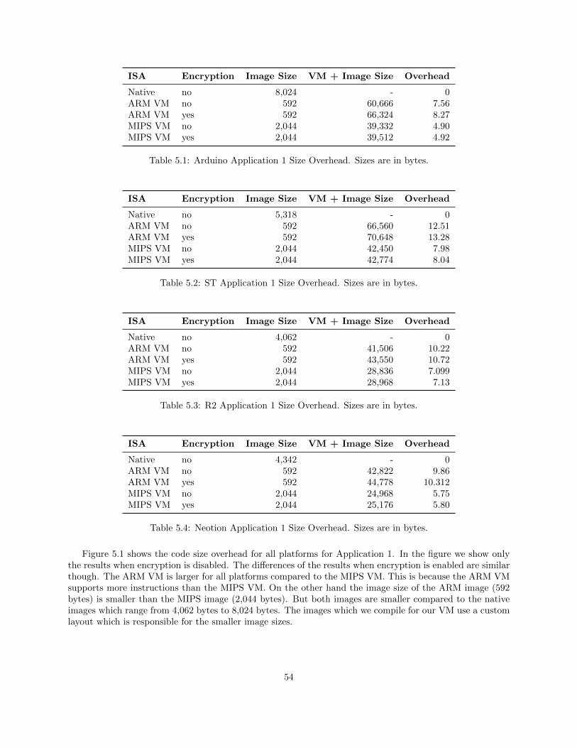
ISA Encryption Image Size VM + Image Size Overhead
Native no 8,024 - 0ARM VM no 592 60,666 7.56ARM VM yes 592 66,324 8.27MIPS VM no 2,044 39,332 4.90MIPS VM yes 2,044 39,512 4.92
Table 5.1: Arduino Application 1 Size Overhead. Sizes are in bytes.
ISA Encryption Image Size VM + Image Size Overhead
Native no 5,318 - 0ARM VM no 592 66,560 12.51ARM VM yes 592 70,648 13.28MIPS VM no 2,044 42,450 7.98MIPS VM yes 2,044 42,774 8.04
Table 5.2: ST Application 1 Size Overhead. Sizes are in bytes.
ISA Encryption Image Size VM + Image Size Overhead
Native no 4,062 - 0ARM VM no 592 41,506 10.22ARM VM yes 592 43,550 10.72MIPS VM no 2,044 28,836 7.099MIPS VM yes 2,044 28,968 7.13
Table 5.3: R2 Application 1 Size Overhead. Sizes are in bytes.
ISA Encryption Image Size VM + Image Size Overhead
Native no 4,342 - 0ARM VM no 592 42,822 9.86ARM VM yes 592 44,778 10.312MIPS VM no 2,044 24,968 5.75MIPS VM yes 2,044 25,176 5.80
Table 5.4: Neotion Application 1 Size Overhead. Sizes are in bytes.
Figure 5.1 shows the code size overhead for all platforms for Application 1. In the figure we show onlythe results when encryption is disabled. The differences of the results when encryption is enabled are similarthough. The ARM VM is larger for all platforms compared to the MIPS VM. This is because the ARM VMsupports more instructions than the MIPS VM. On the other hand the image size of the ARM image (592bytes) is smaller than the MIPS image (2,044 bytes). But both images are smaller compared to the nativeimages which range from 4,062 bytes to 8,024 bytes. The images which we compile for our VM use a customlayout which is responsible for the smaller image sizes.
54
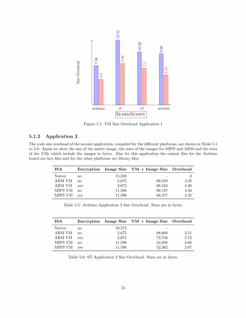
arduino st r2 neotion
7.56
12.51
10.22
9.86
4.9
7.98
7.1
5.75
SizeOverhead
ARM MIPS
Figure 5.1: VM Size Overhead Application 1
5.1.2 Application 2
The code size overhead of the second application, compiled for the different platforms, are shown in Table 5.5to 5.8. Again we show the size of the native image, the sizes of the images for MIPS and ARM and the sizesof the VMs which include the images in bytes. Also for this application the output files for the Arduinoboard are hex files and for the other platforms are library files.
ISA Encryption Image Size VM + Image Size Overhead
Native no 15,248 - 0ARM VM no 2,675 66,348 4.35ARM VM yes 2,675 66,524 4.36MIPS VM no 11,596 66,197 4.34MIPS VM yes 11,596 66,377 4.35
Table 5.5: Arduino Application 2 Size Overhead. Sizes are in bytes.
ISA Encryption Image Size VM + Image Size Overhead
Native no 19,572 -ARM VM no 2,675 68,668 3.51ARM VM yes 2,675 72,756 3.72MIPS VM no 11,596 52,038 2.66MIPS VM yes 11,596 52,362 2.67
Table 5.6: ST Application 2 Size Overhead. Sizes are in bytes.
55
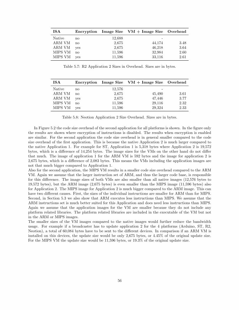
ISA Encryption Image Size VM + Image Size Overhead
Native no 12,688 -ARM VM no 2,675 44,174 3.48ARM VM yes 2,675 46,218 3.64MIPS VM no 11,596 32,984 2.60MIPS VM yes 11,596 33,116 2.61
Table 5.7: R2 Application 2 Sizes in Overhead. Sizes are in bytes.
ISA Encryption Image Size VM + Image Size Overhead
Native no 12,576 -ARM VM no 2,675 45,490 3.61ARM VM yes 2,675 47,446 3.77MIPS VM no 11,596 29,116 2.32MIPS VM yes 11,596 29,324 2.33
Table 5.8: Neotion Application 2 Size Overhead. Sizes are in bytes.
In Figure 5.2 the code size overhead of the second application for all platforms is shown. In the figure onlythe results are shown where encryption of instructions is disabled. The results when encryption is enabledare similar. For the second application the code size overhead is in general smaller compared to the codesize overhead of the first application. This is because the native Application 2 is much larger compared tothe native Application 1. For example for ST, Application 1 is 5,318 bytes where Application 2 is 19,572bytes, which is a difference of 14,254 bytes. The image sizes for the VMs on the other hand do not differthat much. The image of application 1 for the ARM VM is 592 bytes and the image for application 2 is2,675 bytes, which is a difference of 2,083 bytes. This means the VMs including the application images arenot that much bigger compared to Application 1.Also for the second application, the MIPS VM results in a smaller code size overhead compared to the ARMVM. Again we assume that the larger instruction set of ARM, and thus the larger code base, is responsiblefor this difference. The image sizes of both VMs are also smaller than all native images (12,576 bytes to19,572 bytes), but the ARM image (2,675 bytes) is even smaller than the MIPS image (11,596 bytes) alsofor Application 2. The MIPS image for Application 2 is much bigger compared to the ARM image. This canhave two different causes. First, the sizes of the individual instructions are smaller for ARM than for MIPS.Second, in Section 5.3 we also show that ARM executes less instructions than MIPS. We assume that theARM instructions set is much better suited for this Application and does need less instructions than MIPS.Again we assume that the application images for the VM are smaller because they do not include anyplatform related libraries. The platform related libraries are included in the executable of the VM but notin the ARM or MIPS images.The smaller sizes of the VM images compared to the native images would further reduce the bandwidthusage. For example if a broadcaster has to update application 2 for the 4 platforms (Arduino, ST, R2,Neotion), a total of 60,084 bytes have to be sent to the different devices. In comparison if an ARM VM isinstalled on this devices, the update size would be only 2,675 bytes, or 4.45% of the original update size.For the MIPS VM the update size would be 11,596 bytes, or 19.3% of the original update size.
56
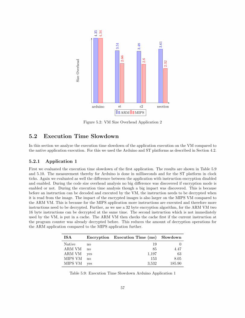
arduino st r2 neotion
4.35
3.51
3.48
3.61
4.34
2.66
2.6
2.32
SizeOverhead
ARM MIPS
Figure 5.2: VM Size Overhead Application 2
5.2 Execution Time Slowdown
In this section we analyze the execution time slowdown of the application execution on the VM compared tothe native application execution. For this we used the Arduino and ST platforms as described in Section 4.2.
5.2.1 Application 1
First we evaluated the execution time slowdown of the first application. The results are shown in Table 5.9and 5.10. The measurement thereby for Arduino is done in milliseconds and for the ST platform in clockticks. Again we evaluated as well the difference between the application with instruction encryption disabledand enabled. During the code size overhead analysis no big difference was discovered if encryption mode isenabled or not. During the execution time analysis though a big impact was discovered. This is becausebefore an instruction can be decoded and executed by the VM, the instruction needs to be decrypted whenit is read from the image. The impact of the encrypted images is also larger on the MIPS VM compared tothe ARM VM. This is because for the MIPS application more instructions are executed and therefore moreinstructions need to be decrypted. Further, as we use a 32 byte encryption algorithm, for the ARM VM two16 byte instructions can be decrypted at the same time. The second instruction which is not immediatelyused by the VM, is put in a cache. The ARM VM then checks the cache first if the current instruction atthe program counter was already decrypted before. This reduces the amount of decryption operations forthe ARM application compared to the MIPS application further.
ISA Encryption Execution Time (ms) Slowdown
Native no 19 0ARM VM no 85 4.47ARM VM yes 1,197 63MIPS VM no 153 8.05MIPS VM yes 3,532 185.90
Table 5.9: Execution Time Slowdown Arduino Application 1
57
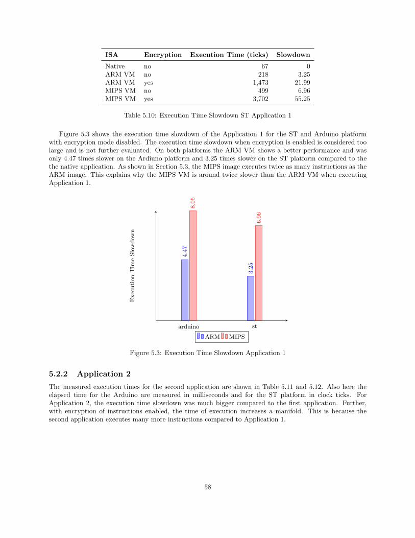
ISA Encryption Execution Time (ticks) Slowdown
Native no 67 0ARM VM no 218 3.25ARM VM yes 1,473 21.99MIPS VM no 499 6.96MIPS VM yes 3,702 55.25
Table 5.10: Execution Time Slowdown ST Application 1
Figure 5.3 shows the execution time slowdown of the Application 1 for the ST and Arduino platformwith encryption mode disabled. The execution time slowdown when encryption is enabled is considered toolarge and is not further evaluated. On both platforms the ARM VM shows a better performance and wasonly 4.47 times slower on the Ardiuno platform and 3.25 times slower on the ST platform compared to thethe native application. As shown in Section 5.3, the MIPS image executes twice as many instructions as theARM image. This explains why the MIPS VM is around twice slower than the ARM VM when executingApplication 1.
arduino st
4.47
3.25
8.05
6.96
ExecutionTim
eSlowdow
n
ARM MIPS
Figure 5.3: Execution Time Slowdown Application 1
5.2.2 Application 2
The measured execution times for the second application are shown in Table 5.11 and 5.12. Also here theelapsed time for the Arduino are measured in milliseconds and for the ST platform in clock ticks. ForApplication 2, the execution time slowdown was much bigger compared to the first application. Further,with encryption of instructions enabled, the time of execution increases a manifold. This is because thesecond application executes many more instructions compared to Application 1.
58
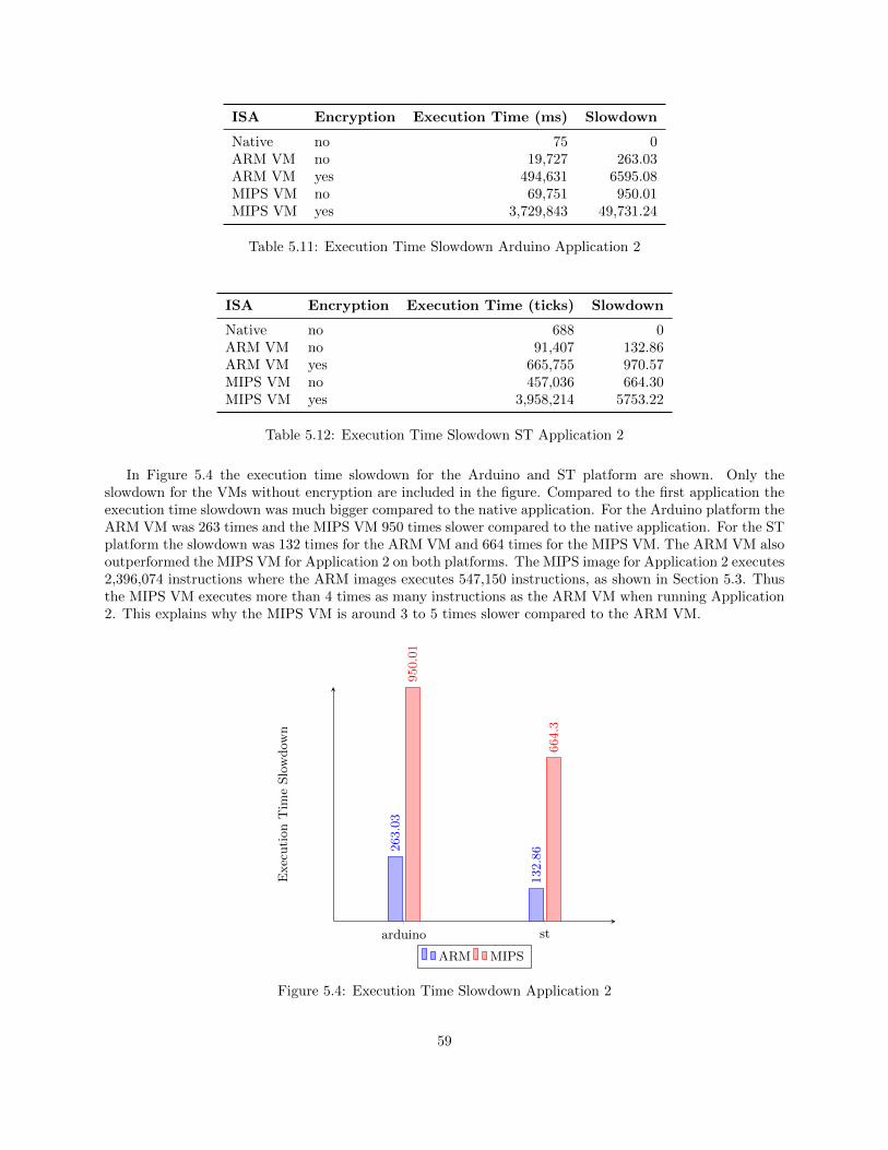
ISA Encryption Execution Time (ms) Slowdown
Native no 75 0ARM VM no 19,727 263.03ARM VM yes 494,631 6595.08MIPS VM no 69,751 950.01MIPS VM yes 3,729,843 49,731.24
Table 5.11: Execution Time Slowdown Arduino Application 2
ISA Encryption Execution Time (ticks) Slowdown
Native no 688 0ARM VM no 91,407 132.86ARM VM yes 665,755 970.57MIPS VM no 457,036 664.30MIPS VM yes 3,958,214 5753.22
Table 5.12: Execution Time Slowdown ST Application 2
In Figure 5.4 the execution time slowdown for the Arduino and ST platform are shown. Only theslowdown for the VMs without encryption are included in the figure. Compared to the first application theexecution time slowdown was much bigger compared to the native application. For the Arduino platform theARM VM was 263 times and the MIPS VM 950 times slower compared to the native application. For the STplatform the slowdown was 132 times for the ARM VM and 664 times for the MIPS VM. The ARM VM alsooutperformed the MIPS VM for Application 2 on both platforms. The MIPS image for Application 2 executes2,396,074 instructions where the ARM images executes 547,150 instructions, as shown in Section 5.3. Thusthe MIPS VM executes more than 4 times as many instructions as the ARM VM when running Application2. This explains why the MIPS VM is around 3 to 5 times slower compared to the ARM VM.
arduino st
263.03
132.86
950.01
664.3
ExecutionTim
eSlowdow
n
ARM MIPS
Figure 5.4: Execution Time Slowdown Application 2
59
5.3 Executed Instructions Analysis
During the execution time slowdown analysis we discovered that the ARM VM is faster than the MIPS VMand that the slowdown of the simpler application was much smaller compared to the second application. Inthis section we give some explanations what the reasons for this are. For this we compare the amount ofguest instructions which are executed for each application for the different VMs.
Application Virtual Machine Number of Guest Instructions
Application 1 ARM 1,032Application 1 MIPS 2,211Application 2 ARM 547,150Application 2 MIPS 2,396,074
Table 5.13: Number of Guest Instructions
From Table 5.13 we can see that the ARM image executes less instructions than the MIPS image forboth applications. This could be as for the ARM VM more instructions are available and less instructionsare needed for the same tasks. Also the MIPS compiler might optimize the code differently compared to theARM compiler. The amount of guest instructions executed for the different VMs, explains the differenceof the execution time between the VMs. The MIPS VM performs around 4 times more instructions andis around 3 to 5 times slower compared to the ARM VM. Further performance difference can be explainedwith the different complexities of instructions.Unfortunately it is very difficult to inspect the number of host instructions which are executed on the differ-ent platforms. Of course we can evaluate the assembly code of the native applications, but it is not easy toextract the information of how many host instructions are executed eventually. This inspection is necessaryto get better insights why the VM performs so much slower than the native application. We assume differentreasons for the slower performance of the VM.First, unfortunately we were not able to compile the VM applications with compile options for speed opti-mization. We suspect that these options make use of features in the instruction set which are not implementedby our VM. Applications which were compiled with this options did not run successfully on our VM. Furtherinvestigation and improvement could enabled the VM to run speed optimized applications. On the otherhand, the native applications and the VM as well, were compiled with speed optimization 02.Further, we can conclude that the native application runs less instructions than the ARM or MIPS applica-tions on the VM. From the ST231 instruction set manual [16], we see that the ST231 includes 170 instructionswhich is more than the instruction sets we implemented. This means it is quite possible that the native STapplication is able to use less instructions than the VM applications. This would already make a differenceof the amount of instructions which are used by the application.Additionally, the second application relies heavily on mathematic calculations for the software AES imple-mentation. We suspect that the ST compiler is able to create optimizations which allow the native applicationto perform such operations much faster than our VM.
60
Chapter 6
Conclusion
In this thesis we created a very small virtual machine which can be used for secure processors in the field ofmedia security. We have proven that it is possible to run the VM on a secure chip and to run applicationson top of it. Further we were even able to use the VM on a much less powerful microcontroller. This VMenables Conditional Access System (CAS) and Digital Rights Management (DRM) vendors to create a singleapplication image for different STBs with different secure chips.The size analysis showed that the size overhead of the VM including the application image is between 2.32to 13.28 times larger than the native application. The size of the VMs thereby ranged from 39 KB to 66 KBfor the Arduino board which was small enough to run the VM on Arduino. For the ST platform the VMsize ranged from 42 KB to 72 KB, which is a feasible size for running on secure chips. No other VM whichsupports MIPS or ARM was discovered which allows such small sizes.Also compared to the native image, the images for the ARM and MIPS VM are smaller. That means furtherbandwidth can be saved by not only reducing the amount of images which have to be sent to the STBs butalso the images size itself. The image for the ARM VM for the second application is only 2.7 KB where thenative images are between 12 KB and 20 KB. This is about 5 times smaller compared to the native images.For example if a broadcaster has four different STBs deployed in the field, similar to the platforms we usedin our analysis, four native images have to be broadcast. In our example of Application 2 this would use60 KB of data to update the application on the platforms. If ARM VMs are deployed on this STBs onlyone image of 2.7 KB has to be sent which is less than 20% of the original data size. In general even moredifferent platforms are deployed in the field, which would allow to save even more bandwidth.The analysis of the execution time overhead showed that encryption of each instruction introduced a bigperformance impact and other security measures should be considered. For a simple application, whichrelies on hardware implementation of cryptographic algorithms, the execution time overhead was between4 and 8 times slower for the Arduino board and 3 to 7 times slower for the ST platform, compared to anative application. This considered the instructions of the applications are not encrypted. This performancelies in the acceptable range. Applications like this could be run on top of a VM in production. For morecomplicated applications, which use software implementations of cryptographic algorithms, the executiontime overhead was much bigger. For the Arduino platform the slowdown was between 263 and 950 times andthe ST platform needed 132 to 664 times longer compared to the native application. These results renderthe VM solution, without further optimization, not feasible for more complicated applications.
61
Chapter 7
Future Work
Our work proved that it is possible to create a very small VM which can be used for less powerful processorsand microcontrollers. The execution time slowdown though is a big issue and could make this solution notpractical for applications with many instructions.One of the biggest challenges, which we were not able to solve, is to make the VM work for speed optimizedimages. Guest images which are compiled with speed optimization will use less instructions and will increasethe speed. Especially for the more complicated second application we assume that with optimization thedifference will be significant.Further analysis and profiling of the VM is also needed to detect other areas where the execution time couldbe improved.In our experiments the MIPS images used more space than the ARM images. As image size is crucial to savebandwidth to update STB images, the compressed MIPS instruction set MicroMIPS could be considered forthe MIPS VM. This would allow to use 16 bit instructions, comparable to the thumb instructions in ARM.We expect that MicroMIPS would allow similar image sizes as the ARM images.The VM we implemented always emulates the guest instruction set. In our case MIPS and ARM. It isalso possible though that the host hardware even supports the guest instructions or a subset of the guestinstructions. For example if a secure chip is based on the ARM architecture. In this case ARM instructionswhich are available on the host platform can directly be performed on the host platform. Further, mostguest architectures have similar instructions as the host architecture which have the same intended effect.In this case the guest instruction can be translated into the host instruction with help of binary translation.The combination of direct instruction execution and binary translation is expected to result in much betterperformance compared to the only emulated approach.One of the big advantages of our VM is the size of the VM. This makes it possible to run the VM onembedded systems or microcontrollers with only limited resources. In this thesis the ST platform and theArduino microcontroller are evaluated. Many different platforms can be evaluated and for example used torun ARM or MIPS applications.A nice feature of the emulation of the instruction set architecture in our VM, is that it allows to inspectdifferent areas of the virtual process during execution of the application image. For example during theexecution of an instruction of the application image, the registers and the stack can be inspected. This canbe useful to debug and inspect ARM or MIPS images. It could be considered to integrate the VM with anuser interface which allows to stop the execution of the application image and is able to display the registersand stack.
62
Bibliography
[1] Global Platform Trusted Excecution Environment. http://www.globalplatform.org/
specificationsdevice.asp. Accessed: 2017-02-11.
[2] Arduino. Arduino Platform. https://www.arduino.cc/. Accessed: 2017-06-15.
[3] NEOTION Company. Neotion Satellite Gateway. http://www.neotion.com/products/
neotion-ott-satellite-gateway.php. Accessed: 2017-06-15.
[4] ALi Corporation. Alitech Set-Top Box Solution. http://www.alitech.com/index.php/en/products.Accessed: 2017-06-15.
[5] W. Roger Davis, Phillip A. Laplante, and Bo I. Sanden. A real-time virtual machine implementationfor small microcontrollers. Innovations in Systems and Software Engineering, 8(3):223–241, 2012.
[6] Tal Garfinkel, Ben Pfaff, Jim Chow, Mendel Rosenblum, and Dan Boneh. Terra: A virtual machine-based platform for trusted computing. In Proceedings of the Nineteenth ACM Symposium on OperatingSystems Principles, SOSP ’03, pages 193–206, New York, NY, USA, 2003. ACM.
[7] MIPS Technologies Inc. MIPS IV Instruction Set Reference. http://math-atlas.sourceforge.net/
devel/assembly/mips-iv.pdf. Accessed: 2017-02-11.
[8] P.C. Kocher, J.M. Jaffe, B.C.M. Jun, C.C. Laren, P.K. Pearson, and N.J. Lawson. Self-protecting digitalcontent, August 9 2011. US Patent 7,996,913.
[9] Philip Levis and David Culler. Mate: A Tiny Virtual Machine for Sensor Networks. In Proceedings ofthe 10th International Conference on Architectural Support for Programming Languages and OperatingSystems (ASPLOS X), October 2002.
[10] ARM Limited. ARMv6-M Architecture Reference Manual. http://infocenter.arm.com/help/index.jsp?topic=/com.arm.doc.ddi0419c/index.html. Accessed: 2017-02-11.
[11] ARM Ltd. ARM TrustZone. https://www.arm.com/products/security-on-arm/trustzone. Ac-cessed: 2017-02-11.
[12] Sri Parameswaran and Tilman Wolf. Embedded systems security—an overview. Design Automation forEmbedded Systems, 12(3):173–183, 2008.
[13] Dan Rosenberg. QSEE TrustZone Kernel Integer Overflow Vulnerability. https://www.blackhat.com/docs/us-14/materials/us-14-Rosenberg-Reflections-On-Trusting-TrustZone-WP.pdf. Ac-cessed: 2017-02-11.
[14] James E. Smith and Ravi Nair. The architecture of virtual machines. Computer, 38(5):32–38, May2005.
[15] STMicroelectronics. ST Digital Set-Top Box Platform. http://www.st.com/en/
digital-set-top-box-ics.html. Accessed: 2017-06-15.
63
[16] STMicroelectronics. ST231 Core and Instruction Set Architecture Manual. http://www.st.
com/content/ccc/resource/technical/document/reference_manual/68/71/ba/97/fc/59/42/
65/CD17645929.pdf/files/CD17645929.pdf/jcr:content/translations/en.CD17645929.pdf.Accessed: 2017-06-15.
[17] Balaji Sundareshan. Digital Set Top Box (STB) -Open Architecture/Interoperability Is-sues. https://www.researchgate.net/publication/267828490_Digital_Set_Top_Box_STB_-Open_ArchitectureInteroperability_Issues. Accessed: 2017-06-15.
64
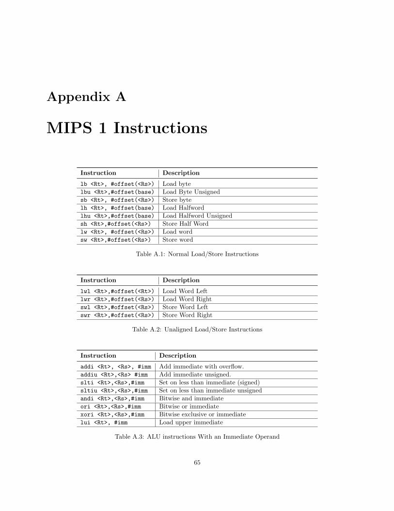
Appendix A
MIPS 1 Instructions
Instruction Description
lb <Rt>, #offset(<Rs>) Load bytelbu <Rt>,#offset(base) Load Byte Unsignedsb <Rt>, #offset(<Rs>) Store bytelh <Rt>, #offset(base) Load Halfwordlhu <Rt>,#offset(base) Load Halfword Unsignedsh <Rt>,#offset(<Rs>) Store Half Wordlw <Rt>, #offset(<Rs>) Load wordsw <Rt>,#offset(<Rs>) Store word
Table A.1: Normal Load/Store Instructions
Instruction Description
lwl <Rt>,#offset(<Rt>) Load Word Leftlwr <Rt>,#offset(<Rs>) Load Word Rightswl <Rt>,#offset(<Rs>) Store Word Leftswr <Rt>,#offset(<Rs>) Store Word Right
Table A.2: Unaligned Load/Store Instructions
Instruction Description
addi <Rt>, <Rs>, #imm Add immediate with overflow.addiu <Rt>,<Rs> #imm Add immediate unsigned.slti <Rt>,<Rs>,#imm Set on less than immediate (signed)sltiu <Rt>,<Rs>,#imm Set on less than immediate unsignedandi <Rt>,<Rs>,#imm Bitwise and immediateori <Rt>,<Rs>,#imm Bitwise or immediatexori <Rt>,<Rs>,#imm Bitwise exclusive or immediatelui <Rt>, #imm Load upper immediate
Table A.3: ALU instructions With an Immediate Operand
65
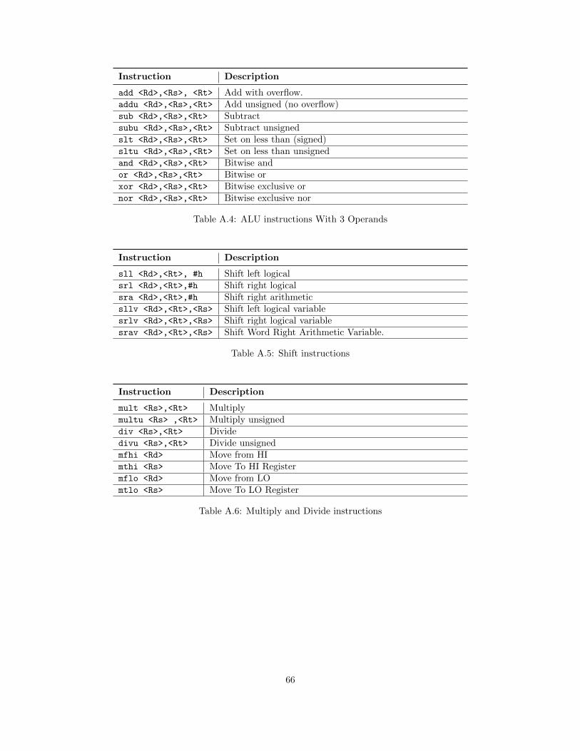
Instruction Description
add <Rd>,<Rs>, <Rt> Add with overflow.addu <Rd>,<Rs>,<Rt> Add unsigned (no overflow)sub <Rd>,<Rs>,<Rt> Subtractsubu <Rd>,<Rs>,<Rt> Subtract unsignedslt <Rd>,<Rs>,<Rt> Set on less than (signed)sltu <Rd>,<Rs>,<Rt> Set on less than unsignedand <Rd>,<Rs>,<Rt> Bitwise andor <Rd>,<Rs>,<Rt> Bitwise orxor <Rd>,<Rs>,<Rt> Bitwise exclusive ornor <Rd>,<Rs>,<Rt> Bitwise exclusive nor
Table A.4: ALU instructions With 3 Operands
Instruction Description
sll <Rd>,<Rt>, #h Shift left logicalsrl <Rd>,<Rt>,#h Shift right logicalsra <Rd>,<Rt>,#h Shift right arithmeticsllv <Rd>,<Rt>,<Rs> Shift left logical variablesrlv <Rd>,<Rt>,<Rs> Shift right logical variablesrav <Rd>,<Rt>,<Rs> Shift Word Right Arithmetic Variable.
Table A.5: Shift instructions
Instruction Description
mult <Rs>,<Rt> Multiplymultu <Rs> ,<Rt> Multiply unsigneddiv <Rs>,<Rt> Dividedivu <Rs>,<Rt> Divide unsignedmfhi <Rd> Move from HImthi <Rs> Move To HI Registermflo <Rd> Move from LOmtlo <Rs> Move To LO Register
Table A.6: Multiply and Divide instructions
66
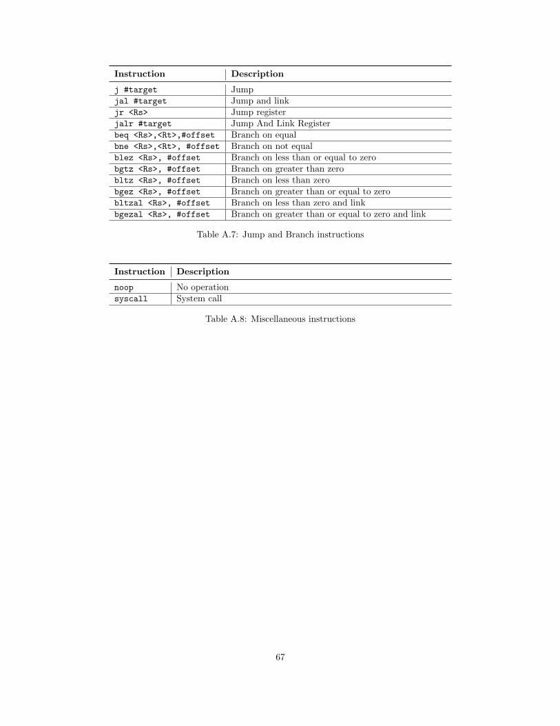
Instruction Description
j #target Jumpjal #target Jump and linkjr <Rs> Jump registerjalr #target Jump And Link Registerbeq <Rs>,<Rt>,#offset Branch on equalbne <Rs>,<Rt>, #offset Branch on not equalblez <Rs>, #offset Branch on less than or equal to zerobgtz <Rs>, #offset Branch on greater than zerobltz <Rs>, #offset Branch on less than zerobgez <Rs>, #offset Branch on greater than or equal to zerobltzal <Rs>, #offset Branch on less than zero and linkbgezal <Rs>, #offset Branch on greater than or equal to zero and link
Table A.7: Jump and Branch instructions
Instruction Description
noop No operationsyscall System call
Table A.8: Miscellaneous instructions
67
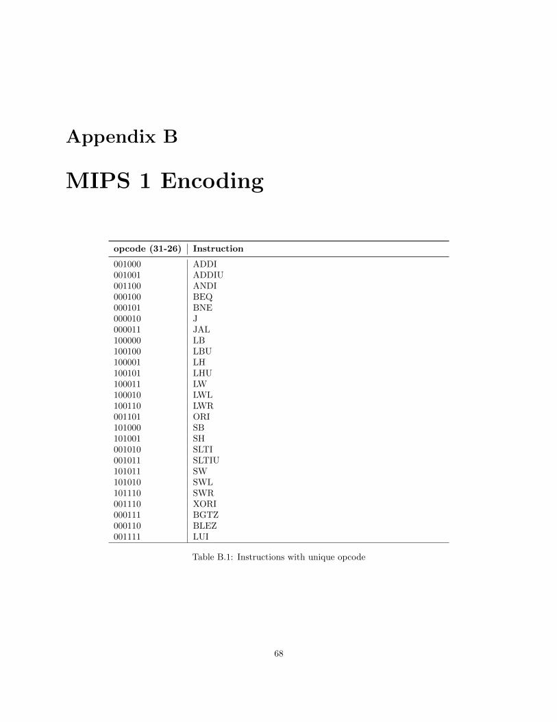
Appendix B
MIPS 1 Encoding
opcode (31-26) Instruction
001000 ADDI001001 ADDIU001100 ANDI000100 BEQ000101 BNE000010 J000011 JAL100000 LB100100 LBU100001 LH100101 LHU100011 LW100010 LWL100110 LWR001101 ORI101000 SB101001 SH001010 SLTI001011 SLTIU101011 SW101010 SWL101110 SWR001110 XORI000111 BGTZ000110 BLEZ001111 LUI
Table B.1: Instructions with unique opcode
68
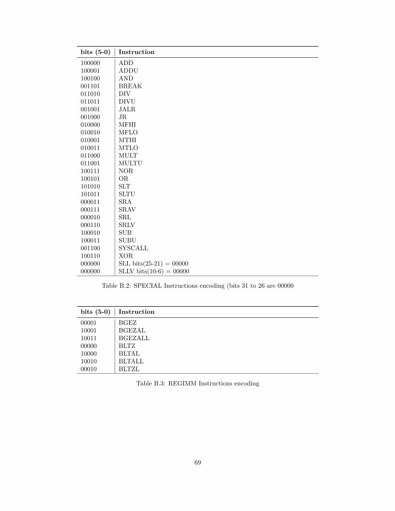
bits (5-0) Instruction
100000 ADD100001 ADDU100100 AND001101 BREAK011010 DIV011011 DIVU001001 JALR001000 JR010000 MFHI010010 MFLO010001 MTHI010011 MTLO011000 MULT011001 MULTU100111 NOR100101 OR101010 SLT101011 SLTU000011 SRA000111 SRAV000010 SRL000110 SRLV100010 SUB100011 SUBU001100 SYSCALL100110 XOR000000 SLL bits(25-21) = 00000000000 SLLV bits(10-6) = 00000
Table B.2: SPECIAL Instructions encoding (bits 31 to 26 are 00000
bits (5-0) Instruction
00001 BGEZ10001 BGEZAL10011 BGEZALL00000 BLTZ10000 BLTAL10010 BLTALL00010 BLTZL
Table B.3: REGIMM Instructions encoding
69
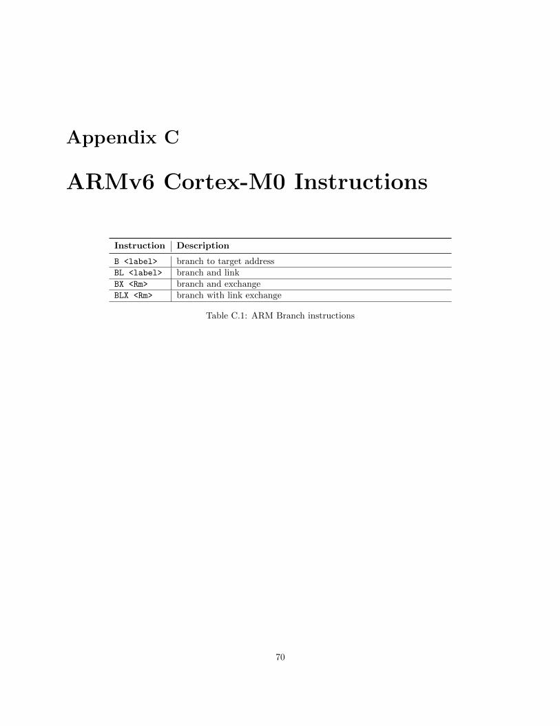
Appendix C
ARMv6 Cortex-M0 Instructions
Instruction Description
B <label> branch to target addressBL <label> branch and linkBX <Rm> branch and exchangeBLX <Rm> branch with link exchange
Table C.1: ARM Branch instructions
70
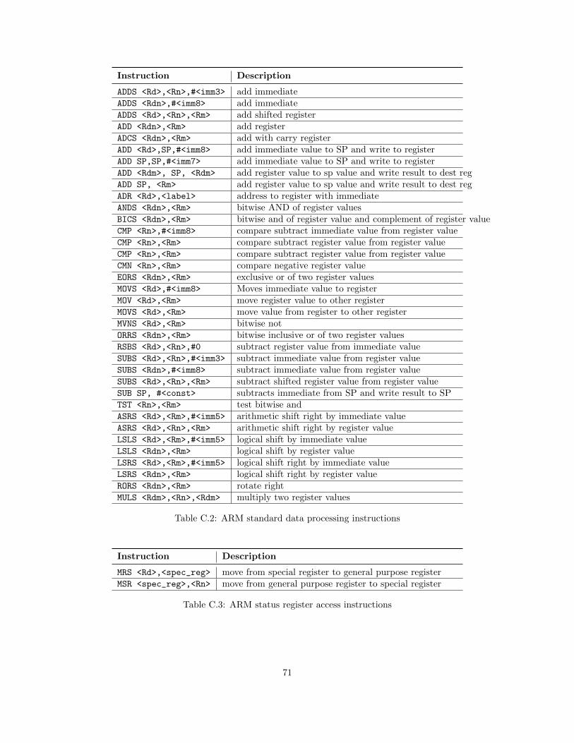
Instruction Description
ADDS <Rd>,<Rn>,#<imm3> add immediateADDS <Rdn>,#<imm8> add immediateADDS <Rd>,<Rn>,<Rm> add shifted registerADD <Rdn>,<Rm> add registerADCS <Rdn>,<Rm> add with carry registerADD <Rd>,SP,#<imm8> add immediate value to SP and write to registerADD SP,SP,#<imm7> add immediate value to SP and write to registerADD <Rdm>, SP, <Rdm> add register value to sp value and write result to dest regADD SP, <Rm> add register value to sp value and write result to dest regADR <Rd>,<label> address to register with immediateANDS <Rdn>,<Rm> bitwise AND of register valuesBICS <Rdn>,<Rm> bitwise and of register value and complement of register valueCMP <Rn>,#<imm8> compare subtract immediate value from register valueCMP <Rn>,<Rm> compare subtract register value from register valueCMP <Rn>,<Rm> compare subtract register value from register valueCMN <Rn>,<Rm> compare negative register valueEORS <Rdn>,<Rm> exclusive or of two register valuesMOVS <Rd>,#<imm8> Moves immediate value to registerMOV <Rd>,<Rm> move register value to other registerMOVS <Rd>,<Rm> move value from register to other registerMVNS <Rd>,<Rm> bitwise notORRS <Rdn>,<Rm> bitwise inclusive or of two register valuesRSBS <Rd>,<Rn>,#0 subtract register value from immediate valueSUBS <Rd>,<Rn>,#<imm3> subtract immediate value from register valueSUBS <Rdn>,#<imm8> subtract immediate value from register valueSUBS <Rd>,<Rn>,<Rm> subtract shifted register value from register valueSUB SP, #<const> subtracts immediate from SP and write result to SPTST <Rn>,<Rm> test bitwise andASRS <Rd>,<Rm>,#<imm5> arithmetic shift right by immediate valueASRS <Rd>,<Rn>,<Rm> arithmetic shift right by register valueLSLS <Rd>,<Rm>,#<imm5> logical shift by immediate valueLSLS <Rdn>,<Rm> logical shift by register valueLSRS <Rd>,<Rm>,#<imm5> logical shift right by immediate valueLSRS <Rdn>,<Rm> logical shift right by register valueRORS <Rdn>,<Rm> rotate rightMULS <Rdm>,<Rn>,<Rdm> multiply two register values
Table C.2: ARM standard data processing instructions
Instruction Description
MRS <Rd>,<spec_reg> move from special register to general purpose registerMSR <spec_reg>,<Rn> move from general purpose register to special register
Table C.3: ARM status register access instructions
71
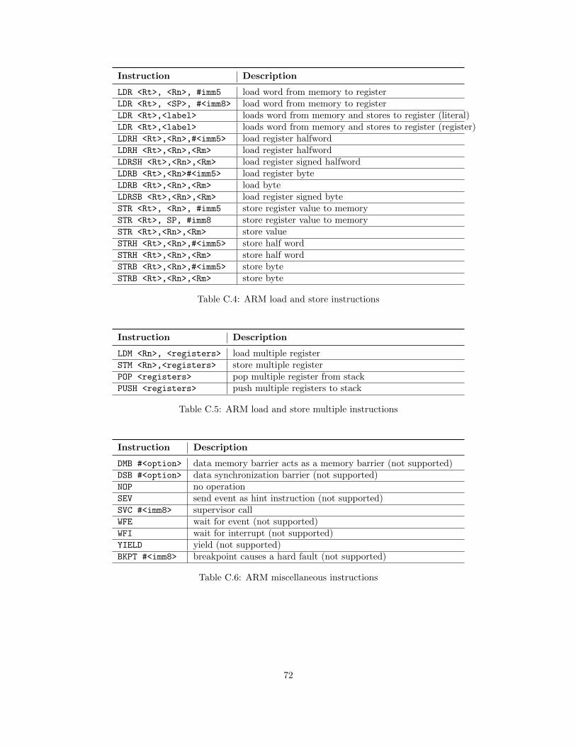
Instruction Description
LDR <Rt>, <Rn>, #imm5 load word from memory to registerLDR <Rt>, <SP>, #<imm8> load word from memory to registerLDR <Rt>,<label> loads word from memory and stores to register (literal)LDR <Rt>,<label> loads word from memory and stores to register (register)LDRH <Rt>,<Rn>,#<imm5> load register halfwordLDRH <Rt>,<Rn>,<Rm> load register halfwordLDRSH <Rt>,<Rn>,<Rm> load register signed halfwordLDRB <Rt>,<Rn>#<imm5> load register byteLDRB <Rt>,<Rn>,<Rm> load byteLDRSB <Rt>,<Rn>,<Rm> load register signed byteSTR <Rt>, <Rn>, #imm5 store register value to memorySTR <Rt>, SP, #imm8 store register value to memorySTR <Rt>,<Rn>,<Rm> store valueSTRH <Rt>,<Rn>,#<imm5> store half wordSTRH <Rt>,<Rn>,<Rm> store half wordSTRB <Rt>,<Rn>,#<imm5> store byteSTRB <Rt>,<Rn>,<Rm> store byte
Table C.4: ARM load and store instructions
Instruction Description
LDM <Rn>, <registers> load multiple registerSTM <Rn>,<registers> store multiple registerPOP <registers> pop multiple register from stackPUSH <registers> push multiple registers to stack
Table C.5: ARM load and store multiple instructions
Instruction Description
DMB #<option> data memory barrier acts as a memory barrier (not supported)DSB #<option> data synchronization barrier (not supported)NOP no operationSEV send event as hint instruction (not supported)SVC #<imm8> supervisor callWFE wait for event (not supported)WFI wait for interrupt (not supported)YIELD yield (not supported)BKPT #<imm8> breakpoint causes a hard fault (not supported)
Table C.6: ARM miscellaneous instructions
72
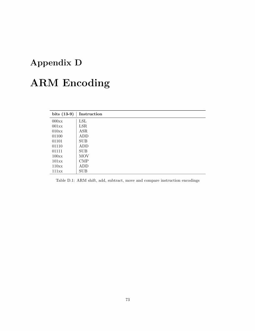
Appendix D
ARM Encoding
bits (13-9) Instruction
000xx LSL001xx LSR010xx ASR01100 ADD01101 SUB01110 ADD01111 SUB100xx MOV101xx CMP110xx ADD111xx SUB
Table D.1: ARM shift, add, subtract, move and compare instruction encodings
73
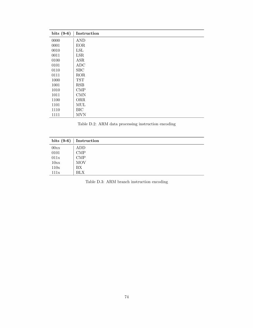
bits (9-6) Instruction
0000 AND0001 EOR0010 LSL0011 LSR0100 ASR0101 ADC0110 SBC0111 ROR1000 TST1001 RSB1010 CMP1011 CMN1100 ORR1101 MUL1110 BIC1111 MVN
Table D.2: ARM data processing instruction encoding
bits (9-6) Instruction
00xx ADD0101 CMP011x CMP10xx MOV110x BX111x BLX
Table D.3: ARM branch instruction encoding
74
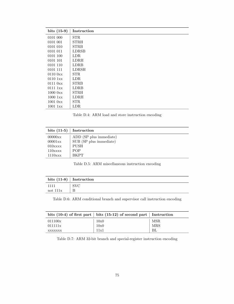
bits (15-9) Instruction
0101 000 STR0101 001 STRH0101 010 STRB0101 011 LDRSB0101 100 LDR0101 101 LDRH0101 110 LDRB0101 111 LDRSH0110 0xx STR0110 1xx LDR0111 0xx STRB0111 1xx LDRB1000 0xx STRH1000 1xx LDRH1001 0xx STR1001 1xx LDR
Table D.4: ARM load and store instruction encoding
bits (11-5) Instruction
00000xx ADD (SP plus immediate)00001xx SUB (SP plus immediate)010xxxx PUSH110xxxx POP1110xxx BKPT
Table D.5: ARM miscellaneous instruction encoding
bits (11-8) Instruction
1111 SVCnot 111x B
Table D.6: ARM conditional branch and supervisor call instruction encoding
bits (10-4) of first part bits (15-12) of second part Instruction
011100x 10x0 MSR011111x 10x0 MRSxxxxxxx 11x1 BL
Table D.7: ARM 32-bit branch and special-register instruction encoding
75
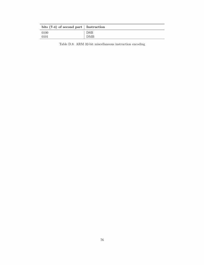
bits (7-4) of second part Instruction
0100 DSB0101 DMB
Table D.8: ARM 32-bit miscellaneous instruction encoding
76