universal vectored space combat main rulebookcoldinfinity.wdfiles.com/local--files/start/main...
TRANSCRIPT

Cold InfinityUvSc
Universal VectoredSpace Combat
Main Rulebook
by Kevin A. Muñoz{Beta Version 01.08.2013}

1.0 IntroductionCold Infinity is a tabletop ship-to-ship space combat
game, focusing on small engagements at the tactical level. The Main Rulebook and the Ship Systems Book
(abbreviated SSB) provide all the rules and tables required to create and play in virtually any space-faring science fiction universe you can imagine.
The Campaign Rulebook adds additional layers to the standard game, providing rules for conducting long-term
campaign games and fleet-level combat.The Universe Book contains a whole background
universe (and ships) that you can use in your games. If you
don’t wish to use the supplied background, you are welcome to develop your own ships: the ship design
options are presented at the end of the Main Rulebook.Many of the rules presented in this rulebook are
considered “advanced” rules. The headings for these rules
are indicated in red, as opposed to the blue headings for the basic rules. Once you have gotten a few games under
your belt and feel confident that you understand the basic structure of the game, begin adding advanced rules to your play so that you can experience the full range of
possibilities. If you are an experienced tabletop space combat gamer, feel free to dive right into the “red” rules.
1.1 What You Will NeedIn addition to the three books (Main, SSB and
Campaign), you will also need the following:
• Dice: You will need at least one 4-sided die (d4), three six-sided dice (d6), one eight-sided die (d8) and one ten-sided die (d10). It will be worthwhile to have at least three of each—preferably one full set for each player!—but this is not required. You could even make do with a single d6, but since a large number of the die rolls in the game require 3d6 (three six-sided dice rolled together), it makes the most sense to have at least three of these dice.
• Playing space: Any large tabletop surface will do. You will also need a large hex map with either 1” hexes (preferred) or 1/2” hexes (in a pinch). A map with 1” hexes is preferred mainly due to the fact that the larger versions of the game’s pieces are more easily handled. But if you are pressed for space, or if you want to have a much larger map area, 1/2” hexes will do just fine.
• Space ship counter cubes: Printable counter cubes are available for all of the ships in the Universe Book. Generic counter cube sheets are also available in the SSB for use with your own creations. Counter cubes designed to be printed on 8.5” x 11” card stock, then cut out and folded into cubes. Although miniatures may be used instead, you will need to find some visual way to indicate ship tumbles and rolls (if you allow them in your game). Counter
cubes are provided for 1” hexes and 1/2” hexes. As noted above, the 1” cubes are much easier to handle; they are also a lot harder to crush accidentally.
• Paper and pencils: Each player will need scratch paper and printouts of the ship designation silhouette sheet for each ship in play, as well as turn-by-turn control sheets for each ship. You may also wish to print out copies of the various data sheets found in the SSB.
• Firing arc cubes and section selection cubes: These are found at the back of the SSB and, like the counter cubes, should be printed on card stock, cut out and folded into cubes. FA cubes and SS cubes are needed only when playing with advanced rules, as they are needed primarily for games that use three dimensional movement.
1.2 Ship DesignBecause Cold Infinity is a universal system, you are
free and encouraged to design your own ships—perhaps ships from an existing roleplaying universe, video game,
television show or movie. Ship and weapon design assumes that you are using the advanced rules, so you should understand how the full set of rules works before
diving into the ship and weapon design instructions.Prefabricated ships (both Basic and Advanced) can be
found in the Universe Book, which includes a narrative history that you may wish to use as the basis of your games. The Universe Book also contains a collection of
weapon systems designed for that universe, which you may use to build your own ships inside or outside the Cold
Infinity Universe.
1.3 TerminologyThe following terms are used throughout the rulebook.
Additional terms will be defined as they appear.
• DRM: Die roll modifier. A DRM is a positive or negative number that is applied to the result of a roll of one or more dice.
• Facing: The direction in which a line passes between the center of a hex and an adjacent hex. Each hex has six facings, numbered 1 through 6 in a clockwise fashion. The term also refers to the boundary line between a unit’s hex and an adjacent hex (called a hex side).
• Hex: A single “space” on the hex map.• Ship: A unit with thrusters (i.e., not a stationary
structure) capable of movement from one hex to another. Starships and small vessels are all considered ships.
• Small Vessel: A fighter or shuttle.• Starship: A unit with thrusters that is larger than a
fighter or shuttle. The largest of these are often called First Rates, Capital Ships or Ships of the Line.

• Stationary Structure: A unit without thrusters that cannot move outside its original hex. Stationary structures are not part of the Basic game.
• Unit: A fighter, shuttle, stationary structure or starship.
1.4 Map and Time ScaleThe units of distance and time in Cold Infinity are
arbitrary, in order to preserve the universality of the game. Different “universes” may have thrusters and weapons with
different base speeds, and designating the size of a hex beforehand may limit players’ ability to simulate their favorite universes.
However, in the absence of a predetermined map and time scale, players may wish to treat the distance across
one hex to be 1 kilometer and the time scale of a single turn to be 15 seconds. Using this scale, accelerating from zero velocity to a Speed of 1 is equivalent to an
acceleration of 1 g (9.8 m/s2).For most purposes, the exact map and time scales used
will not matter for the mechanics of the game. If your Cold Infinity game is part of a larger roleplaying campaign, however, it may matter to know how long the various
characters have between turns.For exceptionally long turn lengths (such as the 7.5
minute turns of a minimum-1g game with 1,000km hexes), it may be worthwhile to think of each turn of combat as consisting of dozens if not hundreds of short maneuvers
and firing volleys. Each game turn, therefore, only represents the “meaningful” events during each period.
Some baseline options are presented below:
MinimumAcceleration
HexSize
TurnLength
1g
1km 15 seconds
1g10km 45 seconds
1g100km 2.5 minutes
1g
1,000km 7.5 minutes
5g
1km 7 seconds
5g10km 20 seconds
5g100km 1 minute
5g
1,000km 3.5 minutes
10g
1km 4.5 seconds
10g10km 15 seconds
10g100km 45 seconds
10g
1,000km 140 seconds
20g
1km 3 seconds
20g10km 10 seconds
20g100km 32 seconds
20g
1,000km 100 seconds
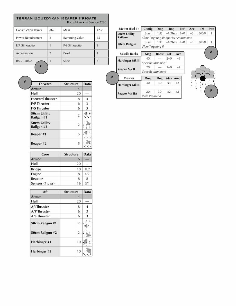
1.5 Ship Designation SilhouetteEvery unit in the game uses a ship designation
silhouette (SDS) as a way to identify and record the systems operated by the unit. The SDS of a unit is a collection of data that describes how the unit moves, detects objects and
inflicts or reacts to damage. An example SDS appears on the next page.
• 1: Information block including construction point cost , uni t Mass , general maneuverabi l i ty (acceleration, pivot, etc.) and power requirements.
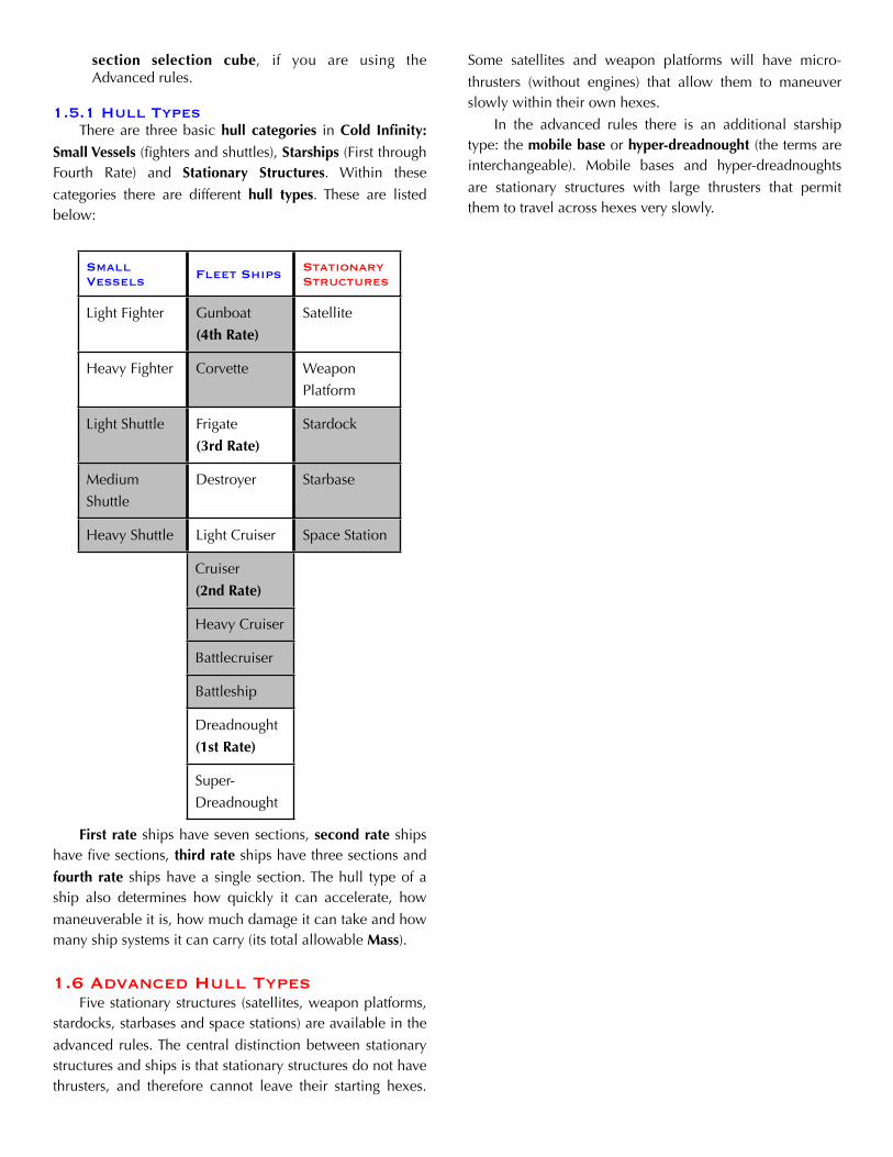
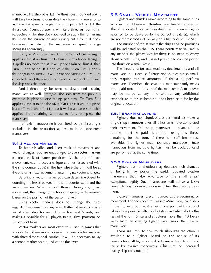
• 2 and 3: Weapon information tables (three), reflecting the details of the weapons mounted on the unit.
• 4: System information for each section of the unit. This ship has three sections (forward, aft, port, starboard and core). Each system is named and shown with the total amount of structure for each. Next to this box is the empty scratch box for marking down lost structure. Weapon firing arcs are given, as well as information specific to certain systems (such as Sensors and Forward Thrusters). At the top of each section is the information for armor and hull structure.
• 5: Hex grid layout for section selection during combat. This diagram is repeated on the relevant
Forward StructureStructure DataArmorHull
Forward ThrusterF/P ThrusterF/S Thruster50cm Utility Railgun #1
50cm Utility Railgun #2
Reaper #1
Reaper #2
4 —20 —
8 46 36 3
2
2
5
5
Terran Bouzdykan Reaper FrigateBouzdykan • In Service 2220
Terran Bouzdykan Reaper FrigateBouzdykan • In Service 2220
Terran Bouzdykan Reaper FrigateBouzdykan • In Service 2220
Terran Bouzdykan Reaper FrigateBouzdykan • In Service 2220
Construction Points 862 Mass 12.7
Power Requirement 8 Ramming Value 25
F/A Silhouette 1 P/S Silhouette 3
Acceleration 2 Pivot 1
Roll/Tumble 1 Slide 3
Matter (Spd 1) Config Dmg Rng RoF Acc DF Pwr
50cm Utility Railgun50cm Utility Railgun
50cm Railgun50cm Railgun
Burst 1d6 –1/2hex 3+0 +3 0/0/0 1Slow Targeting II; Special AmmunitionSlow Targeting II; Special AmmunitionSlow Targeting II; Special AmmunitionSlow Targeting II; Special AmmunitionSlow Targeting II; Special AmmunitionSlow Targeting II; Special AmmunitionSlow Targeting II; Special Ammunition
Burst 1d6 –1/2hex 3+0 +3 0/0/0 1Slow Targeting IISlow Targeting IISlow Targeting IISlow Targeting IISlow Targeting IISlow Targeting IISlow Targeting II
Missiles Dmg Rng Max Amp
Harbinger Mk IIIHarbinger Mk III
Reaper Mk IIAReaper Mk IIA
30 30 x3 +2
20 30 x2 +2Wild Weasel IIWild Weasel IIWild Weasel IIWild Weasel II
Missile Racks Mag Boost RoF Acc
Harbinger Mk IIIHarbinger Mk III
Reaper Mk IIReaper Mk II
40 — 2+0 +3Specific MunitionsSpecific MunitionsSpecific MunitionsSpecific Munitions
20 — 1+0 +2Specific MunitionsSpecific MunitionsSpecific MunitionsSpecific Munitions
1
2
34
5
Aft StructureStructure DataArmorHull
Aft ThrusterA/P ThrusterA/S Thruster
50cm Railgun #1
50cm Railgun #2
Harbinger #1
Harbinger #2
4 —20 —
8 46 36 3
2
2
10
10
Core StructureStructure DataArmorHull
BridgeEngineReactorSensors (4 pwr)
6 —20 –
10 TL28 4/28 816 8/4
section selection cube, if you are using the Advanced rules.
1.5.1 Hull TypesThere are three basic hull categories in Cold Infinity:
Small Vessels (fighters and shuttles), Starships (First through Fourth Rate) and Stationary Structures. Within these
categories there are different hull types. These are listed below:
Small Vessels Fleet Ships Stationary
Structures
Light Fighter Gunboat
(4th Rate)
Satellite
Heavy Fighter Corvette Weapon
Platform
Light Shuttle Frigate
(3rd Rate)
Stardock
Medium
Shuttle
Destroyer Starbase
Heavy Shuttle Light Cruiser Space Station
Cruiser
(2nd Rate)
Heavy Cruiser
Battlecruiser
Battleship
Dreadnought
(1st Rate)
Super-
Dreadnought
First rate ships have seven sections, second rate ships have five sections, third rate ships have three sections and
fourth rate ships have a single section. The hull type of a ship also determines how quickly it can accelerate, how
maneuverable it is, how much damage it can take and how many ship systems it can carry (its total allowable Mass).
1.6 Advanced Hull TypesFive stationary structures (satellites, weapon platforms,
stardocks, starbases and space stations) are available in the
advanced rules. The central distinction between stationary structures and ships is that stationary structures do not have thrusters, and therefore cannot leave their starting hexes.
Some satellites and weapon platforms will have micro-
thrusters (without engines) that allow them to maneuver slowly within their own hexes.
In the advanced rules there is an additional starship type: the mobile base or hyper-dreadnought (the terms are interchangeable). Mobile bases and hyper-dreadnoughts
are stationary structures with large thrusters that permit them to travel across hexes very slowly.

2.0 The Turn SequenceCold Infinity is turn based. Movement, weapons fire
and other operations occur at various points during each turn, as specified by the Turn Sequence Outline. Every
operation in the game has a place in the Turn Sequence, and cannot be performed outside its place in the sequence.
The Basic Turn Sequence is used for games that do not
use the advanced “red” rules. The Advanced Turn Sequence Outline is also found on SSB32.
What follows is a brief overview of the Turn Sequence. More detail will be provided in subsequent sections. Many of the terms used here will be defined and described later
in the Rulebook.Many of the terms used here will be defined and
described later in the Rulebook.
2.1 Preliminary Actions StepDuring the Preliminary Actions Step, players prepare
their ships for movement and weapons fire by allocating power, determining play order (initiative) and assigning
electronic warfare points. Guided weapons are also launched during this step (and then strike their targets during the Weapons Fire Step).
2.1.1 Power Allocation PhaseDuring this phase, starships allocate power from their
power plants, making sure to cover shortages by deactivating systems. They may also add power to systems that can receive extra power for extended or improved
operation.
Small vessels (fighters and shuttles) are not involved in
the power allocation phase.
2.1.1.1 Trans-Light DrivesIn addition to standard power allocation, players may
activate one or more trans-light drives on their ships during this phase. Trans-light drives that are activated in this phase
do not engage until later in the turn (during the Final Actions Step).
2.1.2 Initiative Determination PhaseDuring this phase, every ship on the map determines
initiative order. Initiative is used to determine the order in
which ships move. Initiative is an abstraction of a variety
of different aspects of ship operation, including speed and maneuverability.
Lower Initiative ratings are better. Initiative is
determined for each ship, not once per side. Base initiative (the initiative a ship possesses at the start of the battle) is
equal to the ship’s Mass (rounded to the nearest whole number), as indicated on the ship’s SDS, which will in most cases be a number between 1 and 50. Subtract from this
number half of the ship’s speed, up to a maximum of 10 (speed 20), rounded up. Then roll 1d6. Add the resulting
number to get the ship’s current initiative. For small vessels, initial base initiative is equal to the Mass of the vessel multiplied by the number of vessels in the group.
On every turn after the first, treat the previous turn’s initiative as the Base Initiative and apply the speed and die
roll modifiers described above. It is possible for a ship’s initiative rating to go below zero, but initiative may not
Preliminary Actions Step Power Allocation Phase Resolve power deficiencies Announce deactivations Initiative Determination Phase Initiative determined and declared Electronic Warfare Phase Players secretly determine EW levels Weapon Launch Phase Guided weapon launch
Movement Step Move in initiative order Accelerate, Decelerate, Maneuver Continuing Maneuvers Movement Snap maneuvers
Weapons Fire Step Fire Determination Phase Players secretly determine attacks Players secretly determine DF Players declare attacks and DF Players switch and declare SDF modes Players switch and declare EDF DF allocated against specific shots EW levels announced Guided Weapons Phase Starship Weapons Phase Small Vessel Weapons Phase First systems failure check Fighter vs. fighter Fighter vs. other units
Damage Effects Step Second systems failure check Destroyed sections detach Fighters/shuttles attempt escape
Final Actions Step Hangar operations Cargo operations Reload rack operations
Basic Turn Sequence Outline

Preliminary Actions Step Power Allocation Phase Resolve power deficiencies Power plants recharge Announce deactivations Announce high-density sensor activation Trans-light drive activation In-shifting ships begin to appear In-warping ships begin to appear Initiative Determination Phase Bridge control transfers Electronic Warfare Phase Players secretly determine: EW levels Adaptive armor assignments ESS functions announced Masking sensors toggled Weapon Launch Phase Guided weapon launch Stationary weapon announcement
Movement Step Derelict units move Move in initiative order Partial shifting begins Accelerate, Decelerate, Maneuver Continuing Maneuvers Movement Mid-Step Acceleration Mine activation Drones move Barnstorming resolution Weapon-induced movement Snap maneuvers Rotating sections rotate
Boarding Actions Step (see Campaign Book) Deck Combat resolution Teleporters activate Ramming resolution Entanglement established Attached boarding torpedoes unload Breaching/assault shuttles unload Breaching shuttles attach Assault shuttles attempt landing Voluntary transfers initiated Derelicts captured Escape pods recovered
Weapons Fire Step Fire Determination Phase Players secretly determine attacks, intercept Players secretly determine DF Players declare attacks and DF Players declare guided intercept attempts Players switch and declare SDF modes Players switch and declare EDF DF allocated against specific shots AMRS, Chaff and Flares declared EW levels announced EW Detectors resolved Guided Weapons Phase Intercept attempts made Anti-Missile Rocket Systems fire Chaff and Flares deployed Surviving guided weapons roll to hit Stationary Weapons Phase Docks, bases, stations fire Satellites/weapon platforms fire Stationary weapons deployment Starship Weapons Phase Small Vessel Weapons Phase First systems failure check Fighter vs. fighter Fighter vs. capital/stationary
Damage Effects Step Second systems failure check Special system damage recorded Hyper Drive meltdown/explosion Reactor detonation Ongoing catastrophic effects applied Catastrophic damage rolled Destroyed sections detach Armor reduction Fighters/shuttles attempt escape
Final Actions Step Trans-light drive resolution Hyperspace Tunnels open/close Ships shift/warp Partial shifting ends Ships snap Hangar operations Cargo operations Reload rack operations Docking operations Docked operations Ship Adjustments Phase Repair systems resolution HSR systems accumulate heat Overheating checked HSR capacity checked HSR systems radiate heat Melting HSR systems do damage (Melting HSR systems jettisoned) Hacking attempts resolved
Advanced Turn Sequence Outline

vary by more than 20 points above or below the ship’s
Mass.If two ships are determined to have the same Initiative,
the one with the higher Mass will move before the other. If both have the same Mass, the one with the higher Initiative on the previous turn will move before the other. If the result
is still a tie (or in the case of the first turn, there was no previous Initiative), both ships roll 1d6 and whichever
result is higher moves before the other.It will be clear fairly early that ships that continue to
move (and move quickly) will tend to have lower initiative
scores over time.The results of Initiative determination must be
announced to all players.
2.1.2.1 Fighter Base InitiativeFighters, which are grouped as vanguards, flights and
strike forces (see Rule 12), determine their Base Initiative differently. Multiply the Mass of one fighter by the total
number of fighters in the group (3, 6 or 12) to determine Base Initiative.
2.1.2.2 Bridge Control TransferBefore initiative is determined, players may choose to
transfer ship control from one bridge to another, if their
ships have more than one bridge. (If control of a ship has not been transferred from a destroyed bridge, that ship becomes derelict.)
Bridge control transfers increase the current initiative of the transferring ship by +5. This penalty is not applied on
subsequent turns, although the penalty is included in determining base initiative on the following turn.
2.1.3 Electronic Warfare PhaseDuring this phase, units assign electronic warfare
points to EW shrouds and amplification. This is done in
secret: declaration of the assignment is not done until the Weapons Fire Step.
2.1.3.1 Adaptive Armor and ESS FunctionsAdaptive armor points are assigned during this phase,
after EW points are assigned. Adaptive armor assignments
are not declared until a weapon strikes the adaptive armor.Electronic Support System (ESS) functions are
determined and announced during this phase, and Masking
Sensors may be toggled on or off.
2.1.4 Weapon Launch PhaseUnits firing guided weapons (missiles and torpedoes)
mark their launch instructions. The instructions are kept
secret, only revealed later in the turn, but guided weapon
markers are placed in the hexes where they are launched.
2.1.4.1 Stationary Weapon LaunchUnits deploying stationary weapons (mines, beacons
and weapon platforms) begin to do so at this point, after guided weapon launch. The actual deployment does not
occur until the Final Actions Step. (Stationary weapon counters are not placed at this time.)
2.2 Movement StepIn this step, every unit on the map moves in initiative
order (highest to lowest). Movement is covered in Rule 5.
2.2.1 Simultaneous Movement (Optional Rule)
For added realism, players may choose to ignore
Initiative and simultaneously plot the movements of their vessels. During this step, each player writes down the maneuvers and accelerations/decelerations that he intends
to make, then reveals the movement plot simultaneously with the other players.
All movement plots are final (with the exception of Snap Maneuvers, Rule 5.5.1), and all vessels move at the same time. No changes to a movement plot may be made
after the initial reveal. However, in the event that two or more vessels enter the same hex during the same turn, one
or more players may choose to ram the other unit(s). If this occurs, immediately suspend movement and complete the actions in Rule 15.4. Once the ramming situation has been
resolved, continue resolving movement.
2.2.1.1 Nimble Small Vessels OptionTo preserve the game’s assumption that small vessels
are more agile and maneuverable than starships, players wishing to use simultaneous movement may choose to
have all starships move first, then all small vessels. Movement plots for all starships are revealed before small
vessel movement plots are written down, and once small vessel movement plots are revealed, all vessels move.
2.3 Weapons Fire StepUnlike movement, weapons fire for each unit type
occurs at the same time. Guided weapons strike first,
followed by starships and small vessels.
2.3.1 Fire Determination PhaseDuring this phase, all players secretly determine the
direct fire (non-guided) attacks that they are going to make. They also secretly determine which weapons are
going to be assigned to defensive fire (DF) duties.

After attacks and DF are declared, units may switch
from offensive to defensive fire (if they have that capability). Then, defensive fire is allocated against specific
incoming shots.Finally, all players announce how their electronic
warfare points were assigned during the Preliminary
Actions Step.
2.3.1.1 Other Announcements and EffectsAfter defensive fire allocation, players may announce
that they are using anti-missile rockets, chaff or flares against specific guided weapons.
After EW points are declared, units fielding EW Detectors may activate their effects.
2.3.2 Guided Weapons PhaseGuided weapons launched earlier in the turn attempt
to hit their targets.
2.3.2.1 Guided Weapon InterceptBefore guided weapons make their to-hit roll, target
units may attempt to intercept the weapons using their Defensive Fire-capable systems. In addition, units may fire anti-missile rockets or deploy chaff and flares that were
declared during the Fire Determination Phase.Once the effects of these systems have been
determined, any surviving guided weapons make their to-hit roll attempts.
2.3.3 Stationary Weapon PhaseBefore starships fire their weapons, all weapons from
stationary units (weapon platforms, docks, bases and
stations) fire on their targets. Weapon platforms being deployed complete that operation at this point, though they cannot fire until the next turn.
2.3.4 Starship Weapon PhaseAll direct fire weapons fire from starships is
resolved at this point. Starships may fire on any target.
2.3.5 SMall Vessel Weapons PhaseBefore small vessel weapons can be fired, players must
determine whether any of their small vessels’ systems have
failed due to incoming fire from previous phases. All previously declared weapons that are still functioning may
now be fired.Fighter and shuttle weapons are resolved in two stages:Fighter vs. Fighter: Fighters and shuttles resolve
weapons fire against one another.Fighter vs. Other: Fighters and shuttles resolve
weapons fire against starships and stationary structures.
2.4 Damage Effects StepVarious special effects from damage are resolved in
this step, such as section loss (due to destroyed hull
structure) and system destruction.
2.4.1 Additional EffectsCatastrophic damage is applied to hull structure
during this step, as well as any trans-light drive and power plant detonations. Weapons that cause armor reduction
resolve their effects during this step as well.
2.5 Final Actions StepTrans-light drives complete their operations:
hyperspace tunnels open or close, ships shift or warp, partial shifting ends and snap-ships engage their drives.
Hangar, cargo hold and reload rack operations occur next.
After hangar, cargo and reload rack operations complete, docking operations complete. Transfers of materiel and other docked operation occur last.
2.5.1 Ship Adjustments PhaseDuring this phase, repair systems resolve their effects.
Heat sinks and radiators (HSRs) accumulate heat, and overheating is checked. HSRs then check for capacity overload and radiate heat if possible. HSRs that are melting
down do damage and can then be jettisoned.Finally, any hacking attempts are resolved.

3.0 Power AllocationEvery unit requires a power source in order to provide
the necessary energy to perform combat and other tasks. Different fleets use different types of power sources, but
most starships and stationary structures are designed with enough power to manage the basic operations of every onboard system.
Small vessels do not require power allocation.
3.1 Power PlantsThe power plant of a unit (which may have more than
one) is the source of that unit’s energy. Every system that requires power (which includes most systems) draws from
the unit’s power plant(s). For each point of power required, the system draws one point from the power plant. Some
systems may have additional power allocated to them beyond their minimum operating requirements. In most cases, if you wish to use extra power for one system, you
must deactivate another system to make up the difference. Some units, however, have power plants that provide
excess power, such that systems may be boosted without requiring the deactivation of other systems.
3.1.1 ReactorsA reactor generates a number of points of power each
turn equal to its Rating. Its structure is also equal to its
Rating, and damage to the structure will reduce the reactor’s power output at a 1:1 ratio, one damaged structure point removing one point of power.
Reactors “fill up” completely at the beginning of each turn, to the limits of their Rating (and accounting for power
reduction due to damage). This means that they can provide as much power as their Rating allows on every turn, regardless of how much power was used on previous
turns.
3.1.2 CapacitorsCapacitors hold significantly more power than
reactors, but they recharge at a slower rate. This recharge rate is indicated in their Rating, after the slash. Example: a
capacitor with a Rating of 30/10 holds a maximum of thirty points of power and recharges at a rate of ten points per
turn.Typically, a capacitor’s recharge rate will at least equal
the amount of power required each turn by a unit’s basic,
non-combat systems. Since capacitors have significantly more power available at peak capacity than is necessary to
operate basic systems, units using them will often have considerably more powerful weapons. However, since weapons require power to activate, firing them repeatedly
over many turns will quickly drain a capacitor’s charge.
Use of weapons on a unit with a capacitor that has a recharge rate equal to the power requirement of its basic
systems will require the deactivation of at least one of those systems in order to fully recharge the capacitor.
Example: Consider a unit with a capacitor rated at
30/10 that has basic systems requiring a total of 10 power per turn. This means that at the end of each turn, the
capacitor is holding 20 points of power, and at the beginning of the next turn will recharge to 30 (ten of which will be used again for the basic systems.) If the unit then
fires a weapon that requires 4 power to operate, at the end of the turn the unit will have 16 power, which recharges to
26 at the beginning of the next turn. If the unit fires this weapon once every turn for four more turns, the capacitor will drain to zero points of power—just enough to power
basic systems, since it will have 10 points at the beginning of each turn.
If the unit needs to fire the weapon again, it will have to deactivate 4 points’ worth of basic systems (such as sensors) for a full turn in order to have 14 points at the
beginning of the next, which would allow basic systems and the weapon to be powered.
Damaged capacitors lose power output at a rate of 2 points for every point of damage suffered. Capacitors and reactors cannot be installed together on one unit.
3.1.3 BatteriesBatteries are short-term power sources that do not
recharge themselves. Batteries may only be installed on units that already have self-charging power plants. On any given turn, the unit may divert some of its power from a
self-charging power plant (a reactor or capacitor, for example) into a battery. The battery receives the amount of
power diverted to it, and stores that power for later use.On any future turn, a battery’s power may be used to
activate or boost a system, in place of another power
plant’s energy. The capacity Rating of a battery indicates the total number of points it may store. The convert Rating
reflects how many points of power must be sent to the battery to store one point of power in that battery.
Example: A battery with a capacity Rating of 20 and a
convert Rating of 2 (listed as 20/2) may hold up to 20 points of power, and two points of power from a reactor or
capacitor will convert to one point of battery power. This means that in order to fill the battery, a reactor would need to send 40 points of power to it.
Damaged batteries lose maximum capacity at a rate of 1 battery point for every point of damage suffered.

3.1.4 System BatteriesSystem batteries are, essentially, small batteries
designed to work with only one system each. The power they store may only be used to power the systems to which
they are attached. System batteries will either be extremely efficient but have low capacity (e.g., a Rating of 5/1) or be highly inefficient with great capacity (e.g., a Rating of
50/5).A system battery may power one system only. On any
given turn, that system may be powered by the system battery or another power plant, at the player’s discretion. Because system batteries are housed with their systems and
are extremely volatile (due to either their high efficiency or high capacity), they are instantly destroyed on the first hit
to the attached system, taking one point of damage. System batteries cannot be targeted separately from their systems, and cannot be destroyed by any other means.
3.1.5 Collector PanelsCollector panels generate power by gathering energy
sources such as solar particles, psychic energy or ambient hydrogen. They do not store power on their own; they must transfer it immediately to batteries (or system batteries).
Most are also very inefficient, collecting no more than one point of power each turn. (The sole exception is the
weapon collector panel.)Damaged collectors lose capacity at a rate of 2
collector points for every point of damage suffered. In most
cases this means that a single penetrating hit of any strength will destroy the collector. The advantage to
collector panels, however, is that they are highly redundant: an array of panels can function as well as a reactor, but damage to a single panel will not adversely
affect the rest of the array.
3.2 Activating and Deactivating Systems
Most units will have enough power plant energy to keep every system activated at minimum power. However, there are two circumstances where that will not be the
case:
• Power Plant Damage: If a power plant is damaged, its power output will be reduced.
• Boosting Power: Some systems may have extra power allocated to them to boost their performance or engage certain abilities.
Systems may be activated or deactivated during the
Power Allocation step. A deactivated system cannot be used on the turn during which it is deactivated, or on any subsequent turn, until it is activated again. A system that
has been activated at the Power Allocation step is
immediately available for use (or, in the case of weapons,
can be armed). Weapons that require an arming period may begin the arming procedure on that turn. Weapons
may only fire on their activation turn if they have a rate of fire of at least 1+0.
Weapons that are activated but not armed still draw
power. If they are deactivated, the arming sequence is reset and must begin again once the weapon is reactivated.
If there is not enough power available to the unit to keep all of its systems activated, you must immediately deactivate systems until the power imbalance is corrected.
A unit may never have systems activated that cannot be given power by the unit’s power plants. If a unit loses all of
its power, all systems that require power are immediately deactivated.
Players must announce the deactivation and activation
of systems during the Preliminary Actions Step.
3.2.1 Fighters and ShuttlesFighters and shuttles cannot deactivate their systems,
as their electronics have been simplified to fit within the hull size. A fighter’s or shuttle’s power requirements are not
calculated or tracked.
3.2.2 Forced DeactivationSome weapons can force a unit’s systems to be
deactivated for one or more turns. Forcibly deactivated systems return their power to general availability just as
voluntarily deactivated systems do.Zero-power systems may be forcibly deactivated.
Unpowered systems cannot be forcibly deactivated.
3.3 Zero Power and Unpowered Systems
Some systems are listed as requiring zero power. If
there is no power available from any power plants (as in the case of the complete destruction of a unit’s power
plants), zero-power systems are also deactivated. Voluntarily deactivating a zero-power system does not return any power to general availability.
Although zero power systems do not draw significant power from power plants, if a battery is powering a zero
power system, it consumes 1 point of power every 10 turns. System batteries may not be attached to zero power systems.
Some systems are listed as being unpowered. Unlike zero-power systems, unpowered systems do not draw
power from power plants. They do not need to be deactivated, and will not return power to general availability if they are deactivated.

3.4 Destroyed SystemsIf an activated system is destroyed, it will continue to
draw its standard operating power for a number of turns
equal to its standard operating power requirement. After this interval, the destroyed system no longer draws power. A system cannot be deactivated after it has been destroyed.
Example: A ship is fielding a weapon that requires 3 power. If the weapon is destroyed, it will continue to draw power
for 3 more turns, after which the power returns to general availability.
If an activated system is employing extra power during
the turn on which it is destroyed, that extra power is not drawn by the destroyed system. If a deactivated system is
destroyed, it does not continue to draw power from the power plant(s).
3.5 Application of Extra PowerAll powered systems have a minimum power
requirement. Some may have additional power applied to
them to produce increased or special effects. If the unit has extra power available (due to other deactivations, previously destroyed systems or excess generally available
power), it may be applied to such a system.The specific effects of applied extra power are
described with the system, but there are three basic types of extra power effects:
• Improved Weapon Effects: Many weapons may have extra power applied to add strength to their attacks.
• Improved Sensor Output: Sensor systems may be enhanced to increase their EW capabilities (Rule 4.4).
• Engine Enrichment: Most engines can be boosted with extra power to provide additional thrust energy (Rule 5.3.2).
3.6 OverheatingSome power plants will have the Overheating
limitation (SSB9). An overheating power plant generates
one point of heat for every two points of power used, every turn.
Example: If a power plant with an output Rating of 25
uses 20 of those points for 2 turns, it will generate 10 points of heat per turn, for a total of 20 points of heat.
Once a power plant generates as many points of heat as it has points of power, it automatically shuts down during the Final Actions step. Once the power plant is shut
down, it dissipates two points of heat per turn.Units with overheating power plants may use heat
sinks and radiators, as described in Rule 16.8.2, to mitigate the effect. It is recommended that only advanced players
use the Overheating limitation, as it adds considerably to
the bookkeeping of the game.

4.0 Electronic WarfareElectronic Warfare or EW involves the use of sensor
suites and jamming equipment to defend against enemy weapons and punch through the defenses of enemy units.
The primary source of EW is a unit’s sensor suite (which includes rudimentary jamming equipment), represented as EW points. The first part of a sensor’s Rating
indicates how many EW points may be spent by a starship or stationary structure on any given turn. A unit may spend
its EW points to create EW shrouds or create electronic interference against enemy shrouds.
Small vessels do not normally use electronic warfare;
see Rule 4.3.1 for the exception.
4.1 EW ShroudsAn EW shroud is an “envelope” of space surrounding a
unit that has been “painted” by the unit’s sensors, so that it can identify and track targets in real time.
If an EW shroud is active, the unit is automatically locked onto all enemy units within the shroud’s range. To
activate an EW shroud, apply 1 point of EW for every 10 hexes of shroud range. Thus, 3 points would be required to generate a 30-hex shroud. The shroud covers every hex
within its range, including the hex in which the unit is currently situated. If a shroud is kept active from turn to
turn, it moves with the unit. A unit may change the range of its shroud on each turn, or turn it off completely.
Additional EW points can be assigned to the shroud, as
many as the unit has available. Each EW point adds one level of target amplification against every enemy unit that
is within the shroud during the Weapons Fire Step. Each level of target amplification gives a +1 DRM to hit.
Example: A ship generates a shroud using 3 points,
extending it to 30 hexes. This gives a lock-on to every enemy unit within 30 hexes. The ship then expends 2 more
points, which provides +2 target amplification (+2 DRM) against every enemy unit within the shroud.
Units that are outside the range of the EW shroud
cannot be locked onto or amplified. Against units that are not locked onto, all weapons double their range penalty.
4.2 Electronic CountermeasuresUnits may allocate some of their (unused) EW points to
attempt to jam enemy targeting. They cannot prevent a
lock-on, but every point of EW used for electronic counter-measures (ECM) gives a –1 DRM to hit for most weapons
aimed at the defending unit.
4.3 Small Vessel TargetingFighters and shuttles have simplified sensor suites,
augmented by the pilot’s or gunner’s skill at “eyeballing”
targets. Small vessels do not require lock-ons to avoid increased range penalties, and they do not have EW points. Fighter and shuttle weapons (more specifically, the pilots
and gunners) are able to ignore ECM: they are not penalized by an enemy unit’s ECM allocation.
4.3.1 High-Density SensorsSome fighters will include high-density sensors that
function according to the same rules as the sensors of other units. A fighter may switch between the high-density sensors and visual targeting once per turn.
When a fighter is using high-density sensors, it does require a lock-on to avoid increased range penalties, and
its weapons cannot ignore ECM.Fighters using high-density sensors may use EW points
for ECM, as per the rules for other units. High-density
sensors may not be boosted with extra power (Rule 4.4).Activation of high-density sensors is announced during
the Preliminary Actions Step, but EW levels are announced during the Weapons Fire Step (as normal).
Any weapon that targets sensor systems will affect
high-density sensors when the weapon successfully hits an equipped fighter, along with any other effects of the
weapon.
4.4 Boosting EW with Extra PowerA unit’s sensors may be enhanced on any given turn by
applying extra power to the system. The cost for an additional point of EW is indicated by the second part of
the sensor’s Rating. Example: A sensor with a Rating of 6/4 will have 6 EW points available under normal conditions, and each additional EW point will cost 4 points of power.
4.5 Destroyed and Damaged Sensors
Destroyed sensors may not provide EW points. Extra
power may not be allocated to destroyed sensors, but it may be allocated to damaged sensors.

4.6 Ship Signatures (Optional Rule)
For increased challenge, and to make the game feel
more like a “naval” battle, players may agree to use ship signatures.
Under this rule, every unit has a signature of electronic noise that it produces equal to the amount of power it used for all systems (including weapons and extra power
allocation) on the previous turn. This signature value is applied as a bonus on all attempts to hit the unit.
When using this rule, units should be built with considerably more powerful sensor suites, or with multiple sensor systems, in order to allow for greater ECM
allocation. Alternatively, players may choose to use standard sensor suites but double their sensor Ratings (and
possibly cut their boost Ratings in half).ECM allocation will become significantly more
important, as it must now also mask the unit’s power
output from enemy sensors. (The alternative is to run “silent,” i.e., with reduced power output.)
4.7 Electronic Support SystemsUnits that are equipped with ESS devices are able to
lend targeting and ECM support to friendly units.
ESS devices are similar to sensors. Each ESS device has an ESS Rating that indicates how many ESS points it can
apply. Unlike sensors, however, ESS points cannot be used by the unit to provide its own lock-ons, amplify its own targeting or generate ECM for itself.
ESS devices cannot be boosted by power from the unit’s power plant.
4.7.1 ESS ShroudsAn ESS unit may use its ESS EW points to create a
shroud similar to a standard sensor’s EW shroud. For every
point spent, the ESS shroud extends 8 hexes/layers out from the unit. Thus, they are more expensive to maintain than
EW shrouds.All friendly units within the ESS shroud (except for
small vessels) automatically gain lock-ons to all enemy
units that are also within the ESS shroud.ESS shrouds are a prerequisite for all other ESS
functions. Because of this, ESS units tend to be flag ships or flag escorts, operating at the center of their respective task force.
4.7.2 ESS AmplificationAn ESS unit may use its ESS points to target-amplify
specific enemy units. All friendly units within the ESS unit’s ESS shroud (except for small vessels) may use this target
amplification as if it were their own, in addition to any
target amplification they generate themselves. The enemy unit being amplified must be within the ESS shroud.
4.7.3 ESS CountermeasuresAn ESS unit may use its points to generate ECM for
friendly units. For every 3 ESS points spent, every friendly
unit within the unit’s ESS shroud (including small vessels) receives a point of ECM (–1 DRM to hit).
4.7.4 ESS JammingAn ESS unit may use its points to prevent enemy units
from locking onto other units. It can only do so on a unit-
by-unit basis, however. It requires 3 ESS points to jam one enemy unit (which cannot be a fighter or shuttle) within the
ESS shroud. The enemy unit may continue to use target amplification, but it loses all lock-ons (regardless of source).
4.7.5 ESS NegationAn ESS unit may use its points to negate an enemy
unit’s ESS functions. The enemy unit must be within the ESS unit’s ESS shroud. It requires 5 ESS points to negate one enemy ESS unit.
A negated ESS unit cannot provide ESS amplification, countermeasures or jamming. A negated ESS unit’s ESS
shroud remains active but does not provide lock-on.The only function an ESS unit can operate while
negated is its own ESS negation. If two ESS units are
negating each other, the functions cancel each other out. So long as both ESS units are negating each other, both can
continue to operate as if they were not being negated.
4.7.6 ESS BeaconsESS beacons are mine-sized stationary units that
provide ESS functions. For the purposes of ESS they function as standard ESS units. Computers on board a
beacon will use sophisticated artificial intelligence to operate its functions in an appropriate fashion (at the player’s command).
4.7.7 Multiple ESS UnitsIf two or more ESS units are being used on one side,
only the strongest effect is applied to any given ship (friend or foe).
ESS negation does not cancel out unless the two ESS
units are negating each other. Example: If ESS A is negating ESS B and ESS B is negating ESS C, ESS A may operate all of
its other ESS functions but ESSs B and C may only operate their negation functions. If ESS B shifts its negation points

to ESS A, all three units will be able to operate the full suite
of ESS functions.
4.8 Specialized SensorsIn addition to standard sensors and ESS, there are two
additional electronic warfare systems available: EW Detectors and Masking Sensors.
4.8.1 EW DetectorsEW detectors are special sensor systems that permit
the detecting unit to identify enemy EW allocation. During the Electronic Warfare Phase, a unit with an EW detector may choose to withhold allocation of up to half of its
sensor’s EW points. Then, after EW levels are announced during the Fire Determination Phase, the detecting unit
may allocate the reserved points to EW as desired.
4.8.2 Masking SensorsMasking sensors transmit false sensor data to enemy
units, preventing them from fully determining the unit’s combat stance. Operation of a masking sensor requires two
EW points (allocated from basic sensors). While the sensor is operating, the unit is not required to declare system activations/deactivations during Power Allocation. In
addition, enemies must allocate 1 more point of EW to piercing attacks against the unit than normally required.
4.9 Unit Identification (Optional Rule)
For added realism and tactical complexity, you may wish to limit the amount of information players may
receive about enemy units. If an enemy unit is not within EW shroud range of any allied units, its identity cannot be
determined apart from the number of sections it has. If an enemy unit is within EW shroud range of any allied units but no EW amplification is applied to the shrouds that
contain it, the unit’s Mass is known, but no other details. If any EW amplification is applied to any of the shrouds that
contain the enemy unit, its silhouette is known, and it can be fully identified.
In some games, information may be limited about
enemy units more generally. If no allied faction has encountered the enemy unit before, its silhouette is known
but information about that silhouette is unknown: the best the allies can determine is whether or not the enemy unit matches any it has seen before.
If the unit identification rule is used, the counter cubes used on the map board should be generic until all sides of
the engagement are able to identify the units involved.
It should be noted that the unit identification rule is
relatively unrealistic for any maps with hex diameters less than 1,000 km. Simple telescopes not much more powerful
than those owned by 21st century amateur astronomers would suffice to fully identify ships only a few hundred kilometers away!

5.0 MovementIn the Movement Step, all ships move in Initiative
order, highest to lowest. Because movement in space is unimpeded by atmosphere, ships will continue along their
current trajectories indefinitely until thrust is applied in another direction. Also, ships do not turn in the manner of cars or airplanes: they pivot, tumble and roll instead, and
accelerating thrust is applied afterwards to change the direction of travel. As a result of this, players should make a
habit of planning their maneuvers well ahead of time, as it will usually take at least two turns to make drastic direction changes.
A ship’s Speed determines how many hexes it may travel each turn. The Speed of a ship may be changed by
accelerating and decelerating. A ship’s direction of travel determines the direction it will travel when it moves. Together, Speed and direction of travel constitute the ship’s
vector. The ship’s vector may be changed by maneuvering the ship (usually by pivoting) and then accelerating or
decelerating.
5.1 ThrustersShips are fitted with two kinds of thrusters:
acceleration thrusters and maneuvering thrusters. Acceleration thrusters are generally larger and more
powerful, but cannot be used to change direction. Maneuvering thrusters are used mainly to rotate a ship around one of its axes. They can be used to accelerate, but
they do so much less efficiently.Acceleration thrusters are typically fitted fore and aft
on a ship’s hull, making it possible to accelerate and decelerate. Maneuvering thrusters are typically fitted at multiple points. Under the Basic rules, maneuvering
thrusters will be placed on the port and starboard sides of the ship. This will allow the ship to pivot (“turn” clockwise
or counter-clockwise) or roll (“spin” like an American football).
Thrusters are rated in thrust points. The thrust channel
Rating of a thruster indicates how many points of thrust may be safely channeled from the ship’s engine(s) through
the thruster on each turn.(For games using the three-dimensional rules, ships
should have at least four maneuvering thrusters: forward/
port, forward/starboard, aft/port and aft/starboard. This will permit pivots, rolls and tumbles, as well as slides along the
Z axis. See Rule 5.1.2.5 and Rule 5.4.2.)
5.1.1 Acceleration ThrustTo accelerate or decelerate, a ship channels thrust
though one or more acceleration thrusters. Example: if a
ship channels thrust through an aft acceleration thruster,
the ship will begin to move forward. If it then channels thrust through a forward acceleration thruster, the ship will
slow down.The number of thrust points needed to add (or subtract)
one hex of speed depends on the ship’s hull type. The cost
chart is found on SSB2.If a ship has more than one acceleration thruster on a
side, the player may distribute the required thrust points among them. The distribution does not have to be balanced. Example: An application of 6 thrust through
paired thrusters could be distributed 3-3, but also 4-2, 5-1 or even 6-0, as long as the thruster(s) can handle that
amount of thrust.
5.1.1.1 Deflection VanesDeflection vanes allow an acceleration thruster to be
used as a maneuvering thruster. If an acceleration thruster (or thruster group) is fitted with deflection vanes, the ship
may pivot, roll or tumble using those thrusters, using the thrust cost of a slide. Forward acceleration thrusters may function as forward/port or forward/starboard maneuvering
thrusters. Aft acceleration thrusters may function as aft/port or aft/starboard maneuvering thrusters.
5.1.2 Maneuvering ThrustAs with acceleration thrusters, banks of maneuvering
thrusters may receive distributed thrust.
See Rule 5.4.2 for more on pivots, rolls and tumbles.
5.1.2.1 PivotsThe number of thrust points needed to pivot one facing
per turn also depends on the ship’s hull type. See SSB2 for the cost chart.
To stop the pivot, the ship must apply equal maneuvering thrust in the opposite direction. Most ships
use port maneuvering thrusters to pivot clockwise and starboard maneuvering thrusters to pivot counter-clockwise (and the opposite thrusters to stop the pivot).
Example: A cruiser wishing to pivot clockwise to a reverse facing (pivoting across 3 facings) over three turns
will apply 2 points of thrust to the port maneuvering thruster at the beginning of the pivot. At the beginning of the fourth turn, the ship will apply 2 points of thrust to the
starboard thruster to stop the pivot. (If the ship does not choose or is unable to fire the starboard thruster, the ship
will continue to pivot one facing clockwise each turn.) If the same ship instead wishes to pivot 3 facings over one turn, it will apply 6 points of thrust to port on turn 1 and 6
points of thrust starboard on turn 2.

5.1.2.2 RollsA ship may also use its maneuvering thrusters to roll
along its Y-axis. Port or starboard thrusters (or both) may be
used to start or stop a roll in either direction. The cost to roll 90° per turn is found on the chart on SSB2.
5.1.2.3 SlidesA ship may use its maneuvering thrusters to slide
forward or aft and to port or starboard at the same time.
See Rule 5.4.2.3 for more detail. The costs to increase “sideways” acceleration by 1 hex per turn is found on the chart on SSB2.
5.1.2.4 TumblesWith correctly placed maneuvering thrusters, it is
possible to tumble (“pitch”) along the X axis. The thrust cost for tumbles is the same as the thrust cost for rolls.
5.1.2.5 Maneuvering Thruster PlacementManeuvering thrusters may be placed in a number of
different locations. The most basic solution is to place one
maneuvering thruster each on the port and starboard sides. The port thrusters would pivot clockwise (and could roll port or starboard). The starboard thrusters would pivot
counterclockwise (and could roll port or starboard).An alternative solution, adding redundancy, places two
maneuvering thrusters on either side: one pair forward, one pair aft. The fore/port thruster pivots clockwise. The fore/starboard thruster pivots counterclockwise. The aft thrusters
pivot in opposite directions. A combination of both port thrusters or both starboard thrusters permits rolling (in
either direction). A combination of both forward thrusters or both aft thrusters permits tumbling (in either direction).
If tumbling is permitted in the game but the ship has
only single port and starboard maneuvering thrusters, the ship will also need fore and aft maneuvering thrusters to be
able to tumble.See the chart on SSB35 for a complete list of the
maneuvers available to each thruster. Dark gray blocks
indicate that the thruster can perform the maneuver on its own. Light gray blocks indicate that the thruster can only
perform the maneuver in conjunction with the other thruster(s) with the same letter code.
Example: On the SSB35 chart, the G block under
Tumble Fore indicates that the forward tumble maneuver may be performed by a combination of fore/port and fore/
starboard maneuvering thrusters. The two C blocks under Roll Port indicate that the maneuver may be performed by a combination of fore/port and aft/port maneuvering
thrusters.
5.1.2.6 Maneuvered AccelerationIt is possible to use maneuvering thrusters to accelerate
or decelerate. This is treated as a slide (see Rule 5.4.2.3) for
thrust cost purposes, even though the ship’s acceleration is along its Y axis (and not to the side).
5.2 EnginesThrust points are not generated by thrusters themselves.
They are generated instead by the ship’s engines. The first
portion of an engine system’s Rating indicates how many thrust points it generates on each turn. Thrusters regularly are able to channel far more thrust than their engines
output, and a ship’s movements are usually limited significantly by the Ratings of its engines.
The number of thrust points an engine can produce may be affected by damage to the system. For every two structure points lost, the engine loses one point of thrust
production.Engines may provide thrust to any number of thrusters
on the ship. Any given thruster may receive thrust points from one or more engines.
Example: Consider a cruiser with four aft thrusters,
each with a thrust channel Rating of 3, and an engine with a Rating of 10. Although the set of aft thrusters can receive
a total of 12 thrust points (4 x 3), since the engine only has a Rating of 10, the cruiser (which requires 3 points of thrust to accelerate by one hex) can only accelerate at most 3
hexes on one turn (3 x 3 = 9).
5.3 Extended ThrustA ship’s thrusters and engines may be pushed beyond
their normal limits in two ways.
5.3.1 OverthrustingIf necessary, a player may channel more thrust through
a given thruster than it can normally take; this is called
overthrusting. Overthrusting may be desirable in cases where a ship needs to make an emergency acceleration, or when a ship has lost one or more of the thrusters needed to
perform a maneuver.Doing this creates significant strain on the thruster.
During the Damage Effects Step, roll 2d6 and add the amount of overthrust used. If the result is 10-12, the thruster takes 1 point of damage to structure. If the result is
13 or higher, the thruster takes 2 points of damage.
5.3.2 Engine EnrichmentA ship’s power plant(s) may channel power through an
engine to temporarily increase its output, so long as the

engine has not been destroyed. The second portion of an
engine’s Rating indicates how many points of power convert to one point of thrust.
Example: An engine Rating of 6/2 will generate 6 points of thrust per turn, and 2 points of extra power channeled from a power plant through the engine will
create an additional point of thrust, for a total of 7.Other than the power plant’s output, there is no limit to
the amount of power that may be converted to thrust.
5.4 Moving and ManeuveringAfter a player has assigned thrust points to various
thrusters and once the ship’s turn has come up in the Initiative order, it will move and maneuver according to the
assigned thrust.
5.4.1 MovingIf a ship is stationary or moving in the direction of its
forward facing, acceleration thrust applied forward or aft will either increase or decrease the ship’s speed. (If a ship
is stationary and applies thrust to the forward thrusters, it will begin to move in reverse.) Move the ship in the appropriate direction a number of hexes equal to the ship’s
speed. Example: If a ship has accelerated to speed 5, the player will move the ship counter five hexes in its forward
direction.In many cases, a ship will not be facing its direction of
travel. A ship will always move across the map according to its direction of travel, regardless of the orientation of the ship’s nose. The vector of a ship is how far it will travel on
each turn (its Speed) combined with the direction in which it will travel. The notation of a ship’s vector is Direction
+Speed.A ship may apply acceleration thrust while it is not
facing its vector or the reverse of its vector (facing 180º
away from its direction of travel). In such a case, an additional step is necessary to determine its new vector.
First, locate the hex to which the ship would have traveled if it had not applied the new acceleration thrust. This is Target A. Next, starting from the Target A hex, locate the
hex to which the ship would travel based solely on the new acceleration thrust. This is Target B.
The ship’s new vector is now the line between its current position and Target B. For the purposes of record-keeping, the vector can be understood as the shortest hex
path between the current position and Target B, and can be recorded as a combination of two speeds and directions.
No matter how many times a ship thrusts, the resulting notation will never be more complicated than two directions and two speeds.
The Speed of the new vector is the sum of the Speeds
indicated by the notation.Example: In the diagram below, the ship is traveling at
Speed 4 in direction 2. The ship’s vector notation would be written as 2+4 (direction+speed).
If the ship turns two facings counter-clockwise at the
start of its turn, it will reach its destination four hexes away with its new facing:
If, however, the ship turns two facings counter-clockwise and accelerates by 3, its vector will change:
At the end of its turn, the ship’s new vector will be
1+3,2+1:
(The new vector could also be identified as 2+1,1+3:
direction 2 for one hex, direction 1 for three hexes.)

On subsequent turns, until another vector or facing
change, the ship will be traveling along vector 1+3,2+1 and facing in direction 6. Its speed is the sum of its vector
speeds, i.e, speed 4.
5.4.2 ManeuveringIf a ship’s maneuvering thrusters are activated, the ship
will rotate around one of its axes.
5.4.2.1 PivotsThe most common rotation is a pivot around the Z-axis
(a vertical line perpendicular to the table, going through the center of the counter cube), spinning the ship’s counter
cube clockwise or counter-clockwise a number of facings. As long as a ship has not applied opposite maneuvering
thrust to stop a pivot, it will continue to spin in that direction each turn.
5.4.2.2 RollsRolls are made in 90º increments, spinning the ship
around the Y-axis (a center line down the middle of the
counter cube, front to back), like a thrown American football. To indicate that a unit is rolling, flip the counter cube onto the appropriate side.
Under the Basic rules, it is not permitted to pivot a ship while it is rolling, and a ship may not pivot unless it is face
up or exactly 180° flipped over. (In the latter case, a pivot is possible, but would require maneuvering thrusters opposite the usual ones). However, a ship that is already
pivoting may roll, so long as it does not attempt to stop or increase the pivot until it has rolled through 180º (or 360°)
and ended the roll.Because port and starboard maneuvering thrusters may
be used for either roll direction, it is possible to use a roll
to stop a pivot when the usual maneuvering thrusters needed to stop that pivot have been destroyed. To do this,
the ship uses the remaining maneuvering thrusters to roll through 180º (over one turn or multiple turns—though in the latter case the pivot will continue while the roll is in
progress). Then, those thrusters are used to stop the pivot (since now the pivot’s angle of motion is reversed relative
to the ship’s thrusters). Finally, another roll is applied, through 180º, to bring the ship back to its original roll state.
Ships may accelerate or decelerate while rolling, as normal.
5.4.2.3 SlidesIt is possible for a ship to use its maneuvering thrusters
as if they were acceleration thrusters. This also permits a
ship to accelerate into a hex different from the one toward
which it is facing. This is called sliding.In many cases, slides will only be possible with
considerable overthrusting. The maneuvering thrusters used are those opposite the facing toward which the ship is sliding, just as with acceleration thrusters. Acceleration to
starboard (along the map plane) may move the ship through facing 2 or 3, at the player’s discretion.
Acceleration to port may move the ship through facing 5 or 6.
Slides have the same effect on a ship’s vector as
acceleration away from the direction of travel.
5.4.2.4 TumblesIf a ship has the necessary maneuvering thrusters, it
may tumble forward or aft in the same manner that it rolls. Thrust may be applied through either the forward or aft
maneuvering thrusters, just as with rolls.A ship may not pivot or roll unless it is either face up
or 180º flipped over and no longer tumbling. A ship that is already pivoting may tumble, but a ship that is already rolling may not tumble unless it is face up or 180º flipped
over.Unless the optional three-dimensional movement rules
are being used, a ship may not accelerate or decelerate while it is tumbling unless it is face up or 180º flipped over. If the three-dimensional rules are being used, a ship may
accelerate or decelerate “up” or “down” while in a tumbled position 90º away from the plane of the map.
5.2.2.5 Mid-Step Acceleration (Optional Rule)In the standard rules, acceleration thrust may only be
applied at the start of the Movement Step. However, this
prevents ships from changing vectors more than once per turn, and players must plan the changes well in advance.
Optionally, acceleration thrust may be applied at up to two points during movement (at the beginning and at one other point in the step).
This optional rule adds complexity to the game. Players must mark the ship’s starting hex at the beginning of each
movement step and keep the marker on the map until the end of movement.
To perform a mid-step acceleration, decide (in hexes)
how far along the initial path the ship will be before it makes its turn. Count partial hexes or hex boundaries as
full hexes. Now do a new vector calculation using the ship’s
current (partially moved) location. This determines the
ship’s new vector for subsequent turns. However, since the current movement is already partially completed, a

separate vector must be determined for this turn only. To do
this, subtract the distance the ship has already traveled from its new vector, subtracting one hex and/or hex
boundary (even partial ones) for each hex of previously completed movement.
If this temporary vector lands the ship on a hex
boundary instead of a hex, the player may choose which hex to use as the endpoint for the current turn. This
selection has no effect on subsequent turns, or on the ship’s new vector.
Because all movement takes place on a hex grid but
the movement vectors themselves are not on the hex grid, a ship making a mid-step acceleration may end up in a hex
that is only “glanced” by the vector (see the example below). This is normal and to be expected. Good players will find ways to take advantage of these hex shifts.
Example: A ship is traveling along vector 1+3,2+1, facing direction 6, moving at speed 4, as shown below:
The player decides to move two hexes (out of four)
along the ship’s path before accelerating by 2 along direction 6:
The player determines the new vector based on the
ship’s current location. This new vector is 1+4,6+1:
Finally, the player subtracts the two hexes of prior
movement from the new vector to determine the ship’s endpoint for the current turn:
The ship is now traveling along vector 1+4,6+1 at
speed 5.
5.2.2.6 Off-Axis Maneuvering (Optional Rule)The standard rules do not permit maneuvering while
rolled or tumbled. Adding this advanced optional rule increases complexity but also increases tactical flexibility.
Any maneuver can be made while the ship is in any orientation. Maneuvers that spin the ship along the map
plane use the pivot cost for thrusting. Maneuvers that spin the ship off the map plane use the roll/tumble cost for thrusting. One maneuver must be halted before the next
maneuver can begin.Example: A ship rolls to port and halts the roll, leaving
it in a rolled state. It may “tumble” across facings for the cost it would pay to pivot the same distance under normal conditions.
Example: A ship is tumbled forward. It may “roll” across facings for the cost it would pay to pivot.
5.2.2.7 Partial Thrusting (Optional Rule)If a ship cannot fully apply the necessary thrust for a
maneuver or acceleration/deceleration, it may apply a
portion of the necessary thrust in exchange for a slower
maneuver. If a ship pays 1/2 the thrust cost (rounded up), it
will take two turns to complete the chosen maneuver or to achieve the speed change. If a ship pays 1/3 or 1/4 the
thrust cost (rounded up), it will take three or four turns, respectively. The ship does not need to apply the remaining thrust on the current or any subsequent turn. If it does,
however, the rate of the maneuver or speed change increases accordingly.
Example: A ship requires 4 thrust to pivot one facing. It applies 2 thrust on Turn 1. On Turn 2, it pivots one facing. If it applies no more thrust, it will pivot again on Turn 4, then
Turn 6, and so on. If it applies 2 thrust on Turn 1 and 2 thrust again on Turn 2, it will pivot one facing on Turn 2 (as
expected), and then again on every subsequent turn until the ship ends the pivot.
Partial thrust may be used to slowly end existing
maneuvers as well. Example: The ship from the previous example is pivoting one facing per turn. On Turn 5 it
applies 2 thrust to end the pivot. On Turn 6 it will not pivot, but on Turn 7 (then 9, 11, etc.) it will pivot unless the ship applies the remaining 2 thrust to fully complete the
maneuver.If off-axis maneuvering is permitted, partial thrusting is
included in the restriction against multiple concurrent maneuvers.
5.4.3 Vector MarkersTo help visualize and keep track of movement and
vector changes, you are encouraged to use vector markers
to keep track of future positions. At the end of each movement, each places a unique counter (associated with the ship counter cube) in the hex where the unit will be at
the end of its next movement, assuming no vector changes.By using a vector marker, you can determine Speed by
counting the hexes between the ship counter cube and the vector marker. When a unit thrusts during any given movement, the change (direction and speed) is determined
based on the position of the vector marker.Using vector markers does not change the rules
regarding movement in any way. Rather, it functions as a visual alternative for recording vectors and Speeds, and makes it possible for all players to visualize positions on
subsequent turns. Vector markers are most effectively used in games that
involve two dimensional combat. To use vector markers with three dimensional combat, it will be necessary to lay a second marker on top, indicating the layer.
5.5 Small Vessel MovementFighters and shuttles move according to the same rules
as starships. However, thrusters are treated abstractly. Thrust allocated for acceleration or maneuvering is
assumed to be delivered to the correct thruster(s), which are not represented individually on a fighter or shuttle SDS.
The number of thrust points the ship’s engine produces
will be indicated on the SDS. These points may be used in any manner the player sees fit; there is no need to worry
about overthrusting, and it is not possible to convert power into thrust on a small vessel.
The thrust cost for accelerations, decelerations and all
maneuvers is 1. Because fighters and shuttles are so small, they require minute amounts of thrust to perform
maneuvers. Therefore, the cost of a maneuver only needs to be paid once, at the start of the maneuver. A maneuver may be halted at any time without any additional
expenditure of thrust (because it has been paid for by the original allocation).
5.5.1 Snap ManeuversFighters (but not shuttles) are permitted to make a
single snap maneuver after all other units have completed
their movement. This snap maneuver—a pivot, roll or tumble—must be paid as normal, using any thrust
remaining for the turn. If there is insufficient thrust available, the fighter may not snap maneuver. Snap maneuvers from multiple fighters must be declared (and
are performed) at the same time.
5.5.2 Evasive ManeuversFighters (but not shuttles) may decrease their chances
of being hit by performing rapid, repeated evasive maneuvers that take advantage of the small ships’
exceptional agility. Such maneuvers will act as a DRM penalty to any incoming fire on each turn that the ship uses
them.Evasive maneuvers are announced at the beginning of
movement. For each point of Evasive Maneuvers, each ship
in the fighter group must expend one point of thrust and takes a one point penalty to all of its own to-hit rolls for the
rest of the turn. Ships and structures more than 10 hexes away from an evading fighter may ignore the evasive maneuvers.
There are limits to how much silhouette reduction is available to a fighter, based on the nature of its
construction. All fighters are able to use at least 4 points of thrust for evasive maneuvers. (This may be increased during ship construction.)

Note that thrust used for evasive maneuvers is not
available for acceleration or other maneuvers, and a ship may not use more thrust for evasive maneuvers than is
available to it.
5.5.3 Barnstorming ManeuversSmall vessels and gunboats are able to perform
barnstorming maneuvers against any dreadnought or larger hull type (super-dreadnoughts and the larger stationary
structures). The small units will fly so close to the large unit that it cannot be fired upon, skimming the surface of the ship or structure.
To attempt a barnstorming maneuver, the smaller vessel or vessels must end movement in the same hex as
the larger unit. Then roll 3d6 and apply the following modifiers:
Barnstormer’s Speed 6-10: +2
Speed 11-15: +3Speed 16-20: +5
Speed 21 or greater: +8Barnstormer is facing off vector: +5Target unit is facing off vector: +5
Per lost thruster on barnstormer: +2Evasive maneuvers: +3 per level used
If the result (after modifiers) is 15 or below, the barnstorming is successful and the following take effect:
• The barnstormer(s) may not fire on any other targets using forward weapons. Exception: if opposing units are barnstorming the same larger unit, they may fire at one another with any weapons at their disposal.
• Attempts to hit the barnstormer(s) with a direct fire weapon suffer a called shot penalty (–6). If the weapon misses, the larger unit being barnstormed will take a full hull structure hit instead, automatically.
• Guided weapons launched against the barnstormer(s) before movement will attempt to hit, but if the weapon misses, the larger unit being barnstormed will take a full hull structure hit instead, automatically, with no roll required.
• Forward-facing weapons fire from the barnstormer(s) aimed at the barnstormed unit will automatically hit. The barnstormed unit may not fire defensively against these attacks. (This does not include guided weapons fired earlier in the turn.)
• The barnstormer(s) may not guide guided weapons for the remainder of the turn. Guided weapons fired by the barnstormer(s) earlier in the turn may still attempt to hit their targets, but do not gain any guidance bonus.
On a result of 16-20, the barnstorming is unsuccessful
but successfully disengaged. The above effects do not apply and the units attempting to barnstorm are considered
sufficiently far away from their target that they can be fired
upon without limitation.On any other result (21 or higher), the barnstorming is
unsuccessful and unsuccessfully disengaged. If the barnstormer is a single ship, it automatically rams the larger unit. (See Rule 15.4.) If the barnstormer is a fighter
group, one fighter rams the larger unit for every 5 points of failure above 20, rounded up (21-25, one fighter; 26-30,
two fighters; etc.). The surviving fighters successfully disengage but cannot fire for the rest of the turn. Any guided weapons being guided by the disengaged fighters
automatically miss their targets.
5.6 Cinematic Motion (Optional Rule)
Under the standard rules, there are no limits to the maximum acceleration, deceleration and maneuvering a ship may apply in a single turn, apart from the ship’s
thruster and engine capabilities. This means that, with sufficiently powerful engines and thrusters, super-
dreadnoughts can match fighters in speed and agility. This is realistic, but does not fit well with most science fiction ideas about space combat.
As an optional rule, players may limit a ship’s acceleration, deceleration and maneuvers to a number of
hexes (acceleration/deceleration), facings (pivot) and 90º increments (roll/tumble) per turn as follows:
• Fighter/Shuttle: no limit• Gunboat/Corvette: 5• Frigate/Destroyer/Light Cruiser: 4• Cruiser/Heavy Cruiser/Battlecruiser/Battleship: 3• Dreadnought/Super-Dreadnought: 2• Mobile Base/Hyper-Dreadnought: 1Example: A frigate may accelerate up to 3 hexes per
turn, or pivot up to 3 facings per turn, or accelerate 2 and pivot 1 on the same turn.
5.6.1 Alternative SolutionA better solution for simulating cinematic motion
would be to design larger starships with engine output and/
or thruster channels that are similar to those of smaller starships. A gunboat with an engine Rating of 10/10 will be
much more maneuverable than a super-dreadnought with the same engine, given the thrust costs imposed on those hull types. The most effective way to mandate this is to
permit only a single engine Rating across every ship in the campaign (such as 10/10).

5.7 Disabled and Derelict Ship Movement
If a ship in motion has been disabled due to engine
failure or a loss of thrusters, or has become derelict due to a destruction of its active bridge, it will continue to travel
along its current vector until it impacts something or is able to restore its thrust capability. If the ship is not in a continuous maneuver (pivoting, rolling or tumbling), roll
1d10 on every turn that it has no thrust capability. On a roll of 1, roll 1d6. On a roll of 1-2, it begins to pivot. On a roll
of 3-4, it begins to roll. On a roll of 5-6, it begins to tumble. Roll a third time to determine the direction of the maneuver. Do not perform the 1d10 maneuver check on
subsequent turns. This involuntary maneuver is the result of a failure to perform the micro-thrusting adjustments
necessary to maintain position.
5.8 Special Thruster SystemsSome ships may have engines and thrusters that do not
use exhaust thrust in the manner that is assumed by the preceding rules.
5.8.1 Non-Inertial Engines and Thrusters
Non-inertial thrusters permit significantly smoother maneuvers and, overall, require less thrust (but usually
more power) to operate. Ships with non-inertial engines and thrusters can combine a pivot and vector change in
one maneuver. If desired, a player may announce that s/he is turning the non-inertial ship. The ship then pivots as normal (using maneuvering thrusters) and additionally
expends half the required thrust to accelerate by one hex per turn (rounded up), channeled through any of the ship’s
acceleration thrusters. (This expenditure does not accelerate the ship.) The direction of travel immediately changes by the same number of facings as the pivot. So, for
example, a ship traveling along vector 1+4 that turns one facing to starboard will now be traveling along vector 2+4,
and will not need a Target A-Target B calculation to determine its new vector.
This vector change takes significantly less thrust and
time than an identical vector change on inertial ships. However, there is a tradeoff: low engine efficiency prevents
a ship from making as many or as drastic (high thrust) maneuvers, and any energy conversions allocated by the player will require significant amounts of power for
minimal thrust results. A non-inertial engine will typically have a low Rating for thrust generation and a high Rating
for energy conversion, adapted to its thrust efficiency but reflecting its power-hungry technology.
Beginners who are not yet familiar with most of the
rules should consider playing only with ships carrying non-inertial engines and thrusters until they understand the rest
of the game, or treating all engines and thrusters as if they were non-inertial.
5.8.2 Omni-Directional ThrustersSome ships have omni-directional thrusters, which
may apply thrust in any one direction per turn. These
thrusters are always found in the ship’s core section, but otherwise function like standard thrusters. If a ship has more than one ODT, it may use them independently (i.e.,
more than one direction per turn).For thrust point requirements, omni-directional
thrusters are treated like acceleration thrusters when being used to accelerate and like maneuvering thrusters when being used to pivot, roll or tumble.
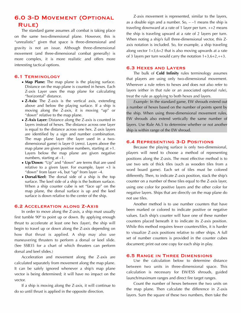
6.0 3-D Movement (Optional Rule)
The standard game assumes all combat is taking place
on the same two-dimensional plane. However, this is “unrealistic” given that space is three-dimensional and
gravity is not an issue. Although three-dimensional movement (and three-dimensional combat generally) is more complex, it is more realistic and offers more
interesting tactical options.
6.1 Terminology• Map Plane: The map plane is the playing surface.
Distance on the map plane is counted in hexes. Each Z-axis Layer uses the map plane for calculating “horizontal” distance.
• Z-Axis: The Z-axis is the vertical axis, extending above and below the playing surface. If a ship is moving along the Z-axis, it is moving “up” or “down” relative to the map plane.
• Z-Axis Layer: Distance along the Z-axis is counted in layers instead of hexes. The distance across one layer is equal to the distance across one hex. Z-axis layers are identified by a sign and number combination. The map plane layer (the layer used in a two-dimensional game) is layer 0 (zero). Layers above the map plane are given positive numbers, starting at +1. Layers below the map plane are given negative numbers, starting at –1.
• Up/Down: “Up” and “down” are terms that are used relative to a given layer. For example, layer +3 is “down” from layer +6, but “up” from layer –4.
• Dorsal/Keel: The dorsal side of a ship is the top surface. The keel side of a ship is the bottom surface. When a ship counter cube is set “face up” on the map plane, the dorsal surface is up and the keel surface is down relative to the center of the ship.
6.2 Acceleration along Z-AxisIn order to move along the Z-axis, a ship must usually
first tumble 90º to point up or down. By applying enough
thrust to accelerate at least one hex (layer), the ship will begin to travel up or down along the Z-axis depending on
how that thrust is applied. A ship may also use maneuvering thrusters to perform a dorsal or keel slide. (See SSB35 for a chart of which thrusters can perform
dorsal and keel slides.)Acceleration and movement along the Z-axis are
calculated separately from movement along the map plane. It can be safely ignored whenever a ship’s map plane vector is being determined; it will have no impact on the
vector.If a ship is moving along the Z-axis, it will continue to
do so until thrust is applied in the opposite direction.
Z-axis movement is represented, similar to the layers,
as a double sign and a number. So, – –1 means the ship is traveling downward at a rate of 1 layer per turn. ++2 means
the ship is traveling upward at a rate of 2 layers per turn. When noting a ship’s full three-dimensional vector, this Z-axis notation is included. So, for example, a ship traveling
along vector 1+3,6+2 that is also moving upwards at a rate of 3 layers per turn would carry the notation 1+3,6+2,++3.
6.3 Hexes and LayersThe bulk of Cold Infinity rules terminology assumes
that players are using only two-dimensional movement.
Wherever a rule refers to hexes and does not also refer to layers (either in that rule or an associated optional rule),
treat the rule as applying to both hexes and layers.Example: In the standard game, EW shrouds extend out
a number of hexes based on the number of points spent by
the ship. When using three-dimensional movement rules, EW shrouds also extend vertically the same number of
layers. Use Rule A6.5 to determine whether or not another ship is within range of the EW shroud.
6.4 Representing 3-D PositionsBecause the playing surface is only two-dimensional,
players will need to choose a method of representing
positions along the Z-axis. The most effective method is to use two sets of thick tiles (such as wooden tiles from a word board game). Each set of tiles must be colored
differently. Then, to indicate Z-axis position, stack the ship’s counter on a number of these tiles equal to the Z-axis layer,
using one color for positive layers and the other color for negative layers. Ships that are directly on the map plane do not use tiles.
Another method is to use number counters that have been marked or colored to indicate positive or negative
values. Each ship’s counter will have one of these number counters placed beneath it to indicate its Z-axis position. While this method requires fewer counters/tiles, it is harder
to visualize Z-axis positions relative to other ships. A full set of number counters is provided in the counter cubes
document; print out one copy for each ship in play.
6.5 Range in Three DimensionsUse the calculation below to determine distance
between two units in three-dimensional space. This calculation is necessary for EW/ESS shrouds, guided
launch/maximum ranges and direct fire target ranges.Count the number of hexes between the two units on
the map plane. Then calculate the difference in Z-axis
layers. Sum the square of these two numbers, then take the

square root of the sum. Round to the nearest whole
number. This is the range to the target.For easier calculation, consult the table on SSB34.
Range 1 is the shorter distance (either map plane or Z-axis). Range 2 is the longer distance. Range 3 is equal to Range 2 plus the number listed. Use Range 3 as the final
calculation.Example: Ship A is 14 hexes away from Ship B. Ship A
is at Z-axis layer +4 and Ship B is at Z-axis layer –6. The difference in Z-axis levels is 10. Therefore R1 is 10 and R2 is 14. Consulting the table, the result for R3 is R2+3, or 17.
Thus, the range between the two ships is 17.In a friendly game, players may choose to calculate
three-dimensional range more simply, by summing the distances (in hexes and layers). However, this will tend to produce exaggerated distances (in the above example, the
result would be 24). It will significantly reduce the range of weapons and EW/ESS shrouds.
7.0 Weapons FireThere are two major types of weapons fire: direct fire
and guided. Rules relevant to both types are found in this section. Rules specific to each type are found in Rule 8 and
Rule 9. Stationary weapon rules (mines, micro-platforms, etc.) are treated in Rule 10.
The application of defensive fire is treated in Rule 11
and the rules for small vessel combat are covered in Rule 12.
7.1 PreparationIn order to be able to fire a weapon during the
Weapons Fire Step, it must meet the following criteria:
• The weapon is activated (Rule 7.1.1)• The weapon is powered (Rule 7.1.2)• The weapon is armed (Rule 7.1.3)• The weapon’s target is within its firing arc (Rule
7.1.4)• The weapon’s target is in line of sight (Rule 7.1.5)If any one of these criteria is not met, the weapon
cannot fire on the current turn. In the case of a guided
weapon, it must have been activated, powered and armed at the Guided Weapon Launch point of the Preliminary Actions Step.
7.1.1 Weapon ActivationA weapon is considered activated if a player has
determined that the weapon is “on.” Deactivated weapons may divert their power requirement to other ship systems; activated weapons may not.
7.1.1.1 CooldownSome weapons must be deactivated between shots;
others must be deactivated after being used for special purposes. Such weapons are said to have a cooldown period.
7.1.2 Weapon PowerWeapon power and activation are directly related to
one another. An activated weapon must also be powered; a powered weapon is automatically activated.
If a ship does not have sufficient power to keep a
weapon activated, the weapon will immediately become deactivated unless power can be diverted to the weapon
from another system.Weapons are powered (and activated) during the
Power Allocation Step. In most cases, players will only
need to keep track of which weapons are powered.

7.1.2.1 CooldownWeapons with cooldown periods cannot be powered
during cooldown; for this reason they must be deactivated.
7.1.2.2 Space TerrainSome space terrain features (Rule CXXX) may interfere
with a ship’s systems, occasionally deactivating weapons without returning power to the ship’s available pool. Under
these conditions, it is possible for a ship to enter such terrain during the Movement Step and as a result have the
weapon be deactivated (after the Power Allocation Step).
7.1.3 Weapon ArmingEvery weapon has a Rate of Fire, indicated by X+Y. X
is the number of shots that can be fired on a turn, and Y is the number of turns the weapon must wait before it can fire
again. A rate of fire of 1+0 indicates that the weapon can fire once every turn. A RoF of 1+1 means the weapon can fire every other turn. A RoF of 2+0 means the weapon can
fire twice every turn.During the turns that a weapon is unable to fire, it is
said to be arming. A weapon will begin arming immediately after being fired, and will continue to arm (until it can fire again) as long as it is activated and
powered. If it becomes deactivated or loses power, the arming sequence is aborted and must be started from
scratch once the weapon is activated and powered again.At the beginning of an engagement during wartime,
every activated and powered weapon is assumed to have
been armed prior to the engagement. Thus, every weapon is capable of being fired on the first turn of the
engagement.
Examples
A weapon is listed as 1+2. If it is fired on Turn 1, it will take two two turns to arm (Turns 2 and 3) and be available
to fire again on Turn 4. If on either Turn 2 or Turn 3 the weapon is deactivated and/or de-powered, the arming cycle is reset. On the turn that the weapon is activated and
powered again, it will begin arming again. If the weapon in this example is deactivated on Turns 3, 4 and 5 and
activated again on Turn 6, it will go through its arming cycle on Turns 6 and 7. It will be capable of firing on Turn 8.
A weapon is listed as 1+2 C-1. If it is fired on Turn 1, it must be deactivated and unpowered on Turn 2 to satisfy the
cooldown period. On Turn 3 it may be activated and powered again, beginning the arming cycle. It will arm on Turns 3 and 4, becoming available for fire on Turn 5.
A weapon is listed as 1+3. If it is fired on Turn 1, it will
take three turns to arm (Turns 2, 3 and 4) and be available to fire again on Turn 4. Unlike the 1+2 C-1 weapon, it must
remain activated and powered during the entire arming cycle. It cannot deactivate on one of the turns to divert power to another system without resetting the arming
cycle.
7.1.3.1 Cooldown vs. ArmingWeapon arming and weapon cooldown are not
identical. A weapon that is in cooldown (deactivated and unpowered) is not arming; a weapon that is arming
(activated and powered) is not in cooldown.Some weapons may have the Emergency Arming
enhancement. This permits the weapon to rapidly arm faster than its regular Rate of Fire, at a damage or Accuracy penalty.
Example: A weapon is listed as 1+2 C-1. If it is fired on Turn 1, it must be deactivated and unpowered on Turn 2 to
satisfy the cooldown period. On Turn 3 it may be activated and powered again, beginning the arming cycle. It will arm on Turns 3 and 4, becoming available for fire on Turn 5.
7.1.4 Firing ArcsEvery weapon has a firing arc, which refers to the
facings out of which the weapon is permitted to fire (facing) and the hexes into which the weapon is permitted to fire (shape).
Under the advanced rules, there are four firing arc shapes: fixed, narrow, standard and wide. The diagrams
below show each of these shapes, using facing 1 for the example. The hexes that are shaded (in whole or in part) can be fired into by weapons using that shape. Note that
the shapes extend beyond the edges of the diagrams.
Fixed Narrow
Standard Wide
There is also a Turret shape, which can target any hex around the ship. On SDS sheets these are indicated as DT
(Dorsal Turret) or KT (Keel Turret). (The distinction between

dorsal and keel turrets is not relevant for two-dimensional
combat. Treat all turrets as dorsal turrets.)
7.1.4.1 Rolling or Tumbling ShipsVisual aids are available to help determine the firing
arcs of rolling or tumbling ships. The full set of firing arc cubes can be found on SSB51-58. If you are only using
two-dimensional combat, print the two-dimensional firing arc cubes at the back of the Advanced Ship Systems Book
(preferably onto card stock), cut them out and fold them into cubes.
Consult the firing arc cubes to determine the firing arcs
of rolled or tumbled ships. To use the cubes, place the appropriate cube in the same orientation as the firing ship
(i.e., tumbled or rolled) and use the firing arc diagram shown on the upper face.
If a ship is rolled to port, all dorsal turrets become
Firing Arc 5/6 Wide (i.e, a Wide arc pointing to the left). If a ship is rolled to starboard, they become Firing Arc 2/3
Wide (pointing to the right). If tumbled forward, turrets become Firing Arc 1 Wide. If tumbled aft, turrets become Firing Arc 4 Wide. The opposite is the case for keel turrets.
7.1.4.2 Abstracted Firing Arcs (Optional Rule)For a faster game, players may wish to use an
abstracted firing arc system instead of the full set of firing arc cubes. Note that these two abstracted systems will change the effectiveness of various tactics that are
dependent on precise firing arc information. Use only one system at a time; they are not compatible with one another.
Abstracted System 1. For the purposes of determining whether or not a weapon may fire at its target, treat every firing arc for every weapon as a Wide arc. If the weapon’s
actual firing arc is Standard, apply a -1 DRM to hit. If the weapons arc is Narrow, apply a -2 DRM to hit. If the
weapon arc is Fixed, apply a -3 DRM to hit.Abstracted System 2. Individual weapons do not use
firing arcs and do not have facings. Using the Standard
firing arc cube, determine which weapon facing can be used to attack the target. If the facing is 1, every weapon
may fire at the target without penalty. For all other facings, use the following table:
Facing To HitDRM Facing
Facing 1/2 or 2 -1 Facing 6 or 6/1
Facing 2/3 -2 Facing 5/6
Facing 3 or 3/4 -3 Facing 4/5 or 5
Facing 4 -4
7.1.4.3 Three-Dimensional Firing Arcs (Optional Rule)
If the optional three-dimensional rules are being used,
print out the three-dimensional firing arc cubes, using the following key:
Gray: ship’s current layerLight blue: one layer downBright blue: two layers down
Green: four layers downOrange: one layer up
Red: two layers upPurple: four layers upBrown: region from one layer down to one layer up
Black: region from two layers down to two layers up0: region from ship’s layer to color layer
+: color layer and all layers up–: color layer and all layers down+ –: all layers
The progressions continue past the edges of the diagrams.
Facings 1 and 2 are marked for guidance purposes. The Port (P) and Starboard (S) sides of the ship are also indicated, and the gray arrow indicates the ship’s nose
facing. If a panel only shows the P indicator, the port side of the ship is facing “up” from the panel. If it only shows
the S indicator, the starboard side of the ship is facing “up.” If a panel indicates (Fore), then the ship’s nose is facing “up” from the panel. If a panel indicates (Aft), then the
ship’s nose is facing “down” from the panel.To use the cubes, place the appropriate cube in the
same orientation as the firing ship and use the firing arc diagram shown on the upper panel.
Examples
Consider the 3D Narrow firing arc 2/3 (pointing directly to starboard). If the ship is in a starting position (no
roll or tumble), use the following panel on the firing arc cube:

Note that the port side of the ship is to the left and the
nose is pointing forward (toward the top). Facing 1 is at the top and facing 2 is two arcs clockwise from facing 1. Firing
arc 2/3 Narrow is on the right side, in the middle.One hex out from the ship’s hex, a weapon with firing
arc 2/3 Narrow can strike targets on the same layer, in the
two hexes partially filled in with gray. Two hexes out from the ship’s hex, the weapon can strike targets on the same
layer and one layer up and one layer down, in the three hexes partially or fully filled in with brown. Following this progression, at three hexes out, the weapon can strike
targets between two layers up and two layers down, in the four hexes that would be partially or fully filled in.
Now consider the same ship rolled 90° to starboard, using the following panel on the same firing arc cube:
On this panel, the P in the center indicates that the port side of the ship is pointing up out of the panel. The nose of the ship is facing the top of the panel. Although the
ship’s weapons are now rolled 90°, the panel displays them as they would be seen from above the ship.
Looking again at firing arc 2/3 Narrow: the display now shows gray, green and bright blue hexes, with negative (–) signs in each hex. The center gray hex with the – sign
indicates that the weapon can strike any target in the same hex and layer, as well as any target in the same hex but in
layers below the firing ship.One hex out, the hexes are bright blue with – signs.
This indicates that the weapon can strike any target in
those hexes as long as it is at least two layers below the ship. Two hexes out, the hexes are green with – signs. This
indicates that the weapon can strike any target in those
hexes as long as it is at least four layers below the ship.Following the progression, three hexes out, the
weapon can strike any target that is at least six layers below the ship.
Rotating the firing arc cube again to show a “flipped
over” position, notice that the panel is a mirror image of the first. Weapon location is therefore reversed: facing 2 is
on the left side of the panel.Turret shapes can fire at targets at any level above or
below the ship, but not both. If a turret normally fires
above the ship (dorsal turret), it follows the rules in 7.1.4.1 for determining shifts from rolling and tumbling. If a turret
normally fires below the ship (keel turret), the arc facings listed there are mirrored (facing 1 becomes facing 4, facings 2-3 become facings 5-6).
7.1.5 Line of SightGiven the vastness of space, most targets will be visible
to the firing unit. However, there are a few exceptions:
• If a straight line between the firing ship and its target passes through any object that is at least half the Mass of the target and closer to the firing ship than the target, line of sight is blocked.
• If the same straight line passes through any object that has a Mass equal to or greater than the target’s Mass, line of sight is blocked, regardless of range.
7.1.5.1 Three Dimensional Line of SightIf three-dimensional movement is being used,
determination of line of sight is slightly more complex. In order to block line of sight, a unit must fit two conditions:
• A straight line along the map plane passes through the potentially blocking unit (according to Rule 7.1.5).
• The Z-axis level of the potentially blocking unit is between the Z-axis levels of the firing unit and the target.
Optionally, the second condition may be made more complex to improve realism. Divide the straight line
between ship and target into two or more segments. Also divide the Z-axis difference between the firing unit and the target into the same number of segments. (For example, if
unit A is at Z +10 and unit B is at Z +4 and there are three segments, the segments are Z +10 to Z +8, Z +8 to Z +6, Z
+6 to Z +4.) If the potentially blocking unit is in the same segment of both the map plane line and the Z-axis line, it blocks line of sight. Otherwise it does not block line of
sight.If the line of sight to the target is blocked, the weapon
may not fire at the target.

7.2 Fire DeterminationDuring the Fire Determination Phase, every player
writes down which weapons will fire and at which targets, as well as any defensive fire settings. Once all players have
marked their weapons, targets and defensive fire, the information is revealed and weapons fire is resolved.
7.2.1 Determine AttacksThe first step of fire determination is to mark down the
attacks you intend to make: which weapons are going to
fire, and at which targets. This information should not be revealed yet.
Use the Turn-By-Turn Control Sheet associated with
each of your ships to mark intended weapons fire. It is suggested that you draw a circle in the turn boxes
associated with the weapons you are firing, and X marks on subsequent turn boxes if those weapons must take time to arm before firing again. (Once a weapon has been fired,
fill in the circle so that you don’t accidentally fire it again!)
7.2.2 Determine Guided InterceptsAfter attacks are determined but before Defensive Fire
is assigned, players may choose to set certain weapons to intercept guided weapons that were fired at the beginning
of the turn. See Rule 11.1.4.
7.2.3 Determine Defensive FireOnce you have determined the attacks you are going
to make, you may set any unused weapons to defensive fire, if they are capable of it. See Rule 11 for more
information on how defensive fire works.On the Turn-By-Turn Control Sheet, mark S for
Standard Defensive Fire and AH for Ad Hoc Defensive Fire.
7.2.4 Declaration of FireOnce everyone has written down their attacks and
defensive fire assignments, all players reveal what they
have marked.
7.2.5 Declare Guided InterceptsDuring this step, all guided intercept attempts are
revealed.
7.2.6 Defensive Fire Mode SwitchingSome weapons (with SDF Ratings) can be switched
from offensive to defensive mode at this point. Weapons that can be used for Emergency Defensive Fire may be
switched to EDF mode now as well.Weapons that have been switched to defensive fire
modes cannot be fired offensively on the current turn.
7.2.7 Allocate Defensive FireNext, all weapons that have been committed to
defensive fire modes must be assigned to specific incoming
attacks. If there are DF mode weapons left over (without attacks to defend), they do nothing on the current turn.
7.2.8 Declare Special Defensive SystemsDuring this step, players may determine and then
declare any uses of anti-missile rocket systems, chaff or
flares. (See Rule 11.5.)
7.2.9 Announce EW LevelsFinally, every player announces their EW point
assignments for the current turn.
7.2.9.1 Resolve EW Detector UsesActivated EW Detectors (see Rule 4.8.1) are declared
and resolved after all players have revealed their EW point assignments.
7.3 Weapons Fire ResolutionAfter fire determination is complete, each attacking
weapon rolls to hit and weapons fire is resolved. Weapons fire is resolved in phases. Within each phase, weapons fire is simultaneous (not resolved in initiative order), but the
phases follow one another in succession. Therefore, if a fighter is attacked and destroyed during the starship
weapons resolution phase, it will be unable to fire during the fighter/shuttle weapons resolution phase. The phases are as follows:
Guided Weapons Phase: This is treated in Rule 9. All damage scored by guided weapons is applied at the end of
this phase.Stationary Weapons Phase: This is treated in Rule 10.
All damage scored by stationary weapons is applied at the
end of this phase.Starship Weapons Phase: All starship units may fire at
any other unit on the map. All damage scored by starships is applied at the end of this phase.
Fighter/Shuttle Weapons Phase: This phase is divided
into two phases. First, fighters and shuttles resolve weapons fire against one another. Damage to fighters and shuttles
(scored by fighters and shuttles) is applied at the end of this sub-phase. Second, fighters and shuttles resolve weapons fire against all other units. Damage to those units scored by
fighters and shuttles is applied at the end of this sub-phase.
7.3.1 Hit ResolutionDuring each weapons fire phase, every player in turn
rolls to hit with his or her weapons, choosing the order in

which to fire multiple weapons if more than one are being
fired. First, determine the target’s dice roll modifier (DRM).The DRM is determined as follows:
• Add the target’s silhouette Rating (Rule 7.3.1.1)• Apply EW points (positive and negative) (Rule 4)• Apply Accuracy modifiers (Rule 7.5)• Apply Range penalties (Rule 7.5)• Apply Evasive Maneuver effects (Rule 5.5.2)• Apply Defensive Fire from the target or any assisting
units (Rule 11)• Apply all relevant Terrain Effect modifiers (Rule
CXXX)
Once the DRM is determined, roll 3d6 and add (or subtract) the DRM. If the result is 10 or below, the weapon
misses.The average result of a 3d6 roll is 10.5. This means that
a DRM of zero or greater produces a greater than 50% chance of hitting the target. A DRM less than zero produces a less than 50% chance of hitting the target.
7.3.1.1 Silhouette RatingEach ship has two silhouette Ratings: Forward/Aft (F/
A) and Port/Starboard (P/S). These ratings indicate how much of the ship is exposed to the attacker’s weapon.
Use the diagrams below to determine the Rating used
during hit resolution. (Treat the black hex as the target unit’s hex.) For targets with a P/S Rating larger than the F/A
Rating, use the diagram on the left. For targets with a F/A Rating larger than the P/S Rating, use the diagram on the right. Fire incoming through the white hexes uses the P/S
Rating. Fire incoming through the gray hexes uses the F/A Rating. The attacker may select which Rating to use if the
fire is coming from a hex that is mixed white and gray.
If the target’s silhouette Ratings are identical, the attacker may choose which of the two diagrams to use for
determining the applicable Rating.For rolled or tumbled targets, use the following chart to
determine the silhouette Rating to use:
Target Status
Tumbled Use P/S RatingDetermine as if not
tumbled
RolledDetermine as if
not rolledUse F/A Rating
When determining whether a guided weapon hits its
target, the silhouette Rating used is based on the line of sight between the weapon’s launch point and the target,
not the current line of sight between the firing ship and the target.
7.3.1.2 Three-Dimensional Silhouette SelectionFor three-dimensional combat, determine the
silhouette Rating based on the table below. If the attacker
and target units are on the same Z-axis layer, treat the attack as two-dimensional.
Target Status
Z-axis Distance >Map Plane Distance
Map Plane Distance > Z-Axis Distance
Not Rolledor Tumbled
Greater ofF/A and P/S
Determine as if 2-D
Tumbled F/A Rating P/S Rating
Rolled P/S Rating F/A Rating
7.4 Damage ResolutionOnce it has been determined that a weapon hit its
target, it does damage to that target. Roll for damage
according to the rules for the weapon being fired (see Rule 8 and Rule 9). If the roll to hit was 11 or 12, divide the damage roll result in half before applying it to the target
(rounding up). Weapons that do half damage to structure will do
quarter damage on a roll of 11 or 12. Weapons that do double damage to structure will do normal (full) damage on a roll of 11 or 12.

7.4.1 Hit LocationMost ships are divided into three or more sections,
with ship systems arranged within these sections. Fighters and shuttles take damage differently. (See Rule 12.)
7.4.1.1 Unit SectionsFourth Rate ships have a single section, which will
take damage from any direction.
Third Rate ships have three sections, usually forward, aft and core. Weapons fire originating from in front of the
center of the ship will strike the forward section. Weapons fire originating from behind the center of the ship will strike the aft section. The core section will be hit either due
to a very good shot (Rule 7.5.1.3) or due to the loss of one of the outer sections. Some Third Rate ships will have port
and starboard sections instead of forward and aft.Second Rate ships have five sections: forward, aft, port,
starboard and core. If weapons fire used the F/S silhouette
for the to-hit roll, the damage affects the forward or aft section. If it used the P/S silhouette, the damage affects the
port or starboard section.First Rate ships have seven sections. The first six are
labeled (clockwise) forward, forward starboard, aft
starboard, aft, aft port and forward port. These sections correspond to facings 1 through 6, respectively. The
seventh section is the core section.Large stationary structures have nine or eleven
sections: three or five core sections with six outer facing
sections. A unit with nine sections has a core of three sections configured like a third rate ship. A unit with eleven
sections has a core of five sections configured like a second rate ship.
7.4.1.2A Basic Section SelectionUse the section selection diagrams below for the target
ship to determine which section is struck by weapons fire.
Weapons that strike the “seam” between sections will strike whichever of the two sections the attacker chooses.
Ships with five or seven sections that are rolled 90° are
treated like ships with three sections: fire originating from the front will strike the forward section (or section #1),
while fire originating from the rear will strike the aft section (or section #4).
Note that the diagram used for ships with five sections
will depend on their Silhouette Ratings, as in Rule 7.3.1.1.
3 Sections 5 Sections 7 Sections
7.4.1.2B Advanced Section SelectionVisual aids are available to help determine which
section is hit by incoming fire. Print the three section selection cubes at the back of the Advanced Ship Systems
Book (preferably onto card stock), cut them out and fold them into cubes.
The first cube reflects attacks on a ship with three
sections. In the “upright” position (the ship is not rolled or tumbled), attacks originating from the front of the ship hit
the forward section. Attacks originating from the rear of the ship hit the aft section. Tip the counter cube to the left or right to show the effects of being rolled to port (Roll P) or
starboard (Roll S). In the case of a ship with three sections, there is no change. The same is true for rolls or tumbles
that leave the ship at at 180º position relative to “upright.” As with firing arcs, attacks from hexes that are partly shaded and partly unshaded may choose the target section.
If the ship is tumbled forward (tip the counter forward), attackers on the same Z-axis layer as the defending ship
may select which section to hit. In three-dimensional combat, attacks coming from below the ship will hit the forward section, while attacks coming from above will hit
the aft section. If the ship is tumbled aft (Tumble A), the sections are reversed.
The section selection cube for ships with five sections is slightly more complex. The upright and 180º section hits depend on the overall shape of the defending ship (whether
the F/A silhouette is greater than the P/S silhouette, or the reverse). The effects of rolls to port or starboard depend on
whether or not the attacker is above or below the ship. If the attacker is on the same Z-axis layer, either the forward or aft section will be hit. If the attacker is above or below,
weapons will strike either the port or aft section.If the defending ship is tumbled forward or aft and the
attacker is above or below, calculate the vertical and horizontal distances between the two units. Resolve the
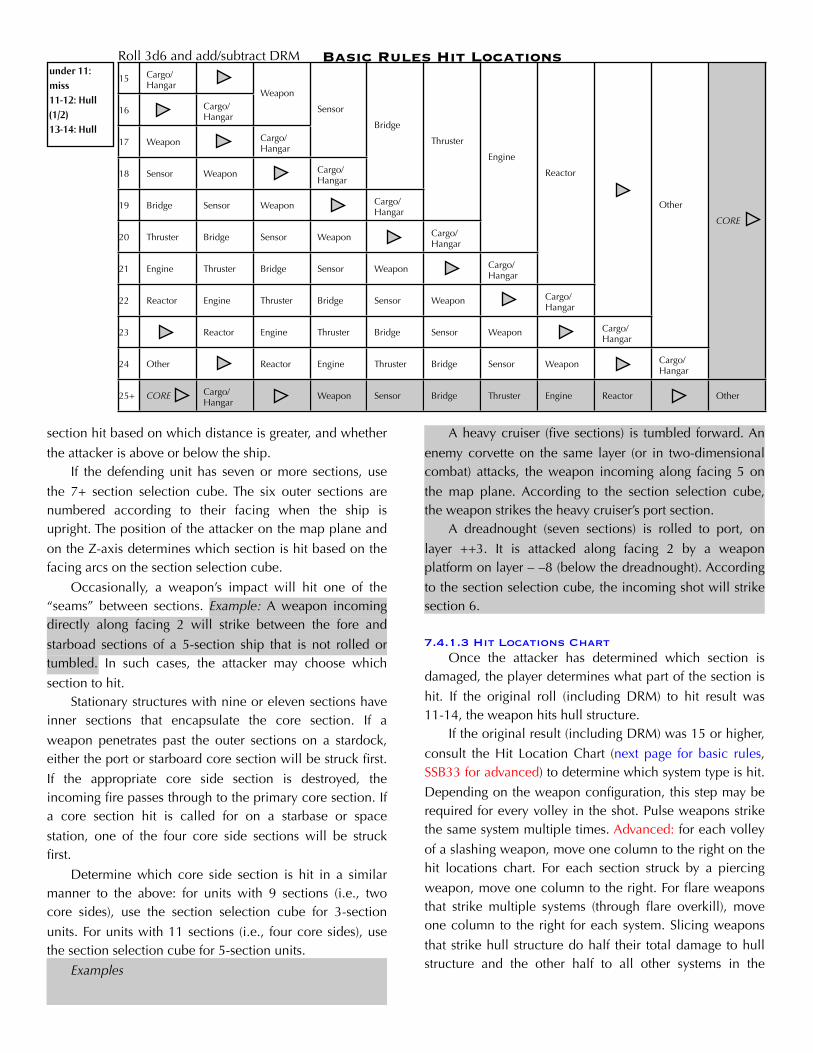
section hit based on which distance is greater, and whether
the attacker is above or below the ship.If the defending unit has seven or more sections, use
the 7+ section selection cube. The six outer sections are numbered according to their facing when the ship is upright. The position of the attacker on the map plane and
on the Z-axis determines which section is hit based on the facing arcs on the section selection cube.
Occasionally, a weapon’s impact will hit one of the “seams” between sections. Example: A weapon incoming directly along facing 2 will strike between the fore and
starboad sections of a 5-section ship that is not rolled or tumbled. In such cases, the attacker may choose which
section to hit.Stationary structures with nine or eleven sections have
inner sections that encapsulate the core section. If a
weapon penetrates past the outer sections on a stardock, either the port or starboard core section will be struck first.
If the appropriate core side section is destroyed, the incoming fire passes through to the primary core section. If a core section hit is called for on a starbase or space
station, one of the four core side sections will be struck first.
Determine which core side section is hit in a similar manner to the above: for units with 9 sections (i.e., two core sides), use the section selection cube for 3-section
units. For units with 11 sections (i.e., four core sides), use the section selection cube for 5-section units.
Examples
A heavy cruiser (five sections) is tumbled forward. An
enemy corvette on the same layer (or in two-dimensional combat) attacks, the weapon incoming along facing 5 on
the map plane. According to the section selection cube, the weapon strikes the heavy cruiser’s port section.
A dreadnought (seven sections) is rolled to port, on
layer ++3. It is attacked along facing 2 by a weapon platform on layer – –8 (below the dreadnought). According
to the section selection cube, the incoming shot will strike section 6.
7.4.1.3 Hit Locations ChartOnce the attacker has determined which section is
damaged, the player determines what part of the section is
hit. If the original roll (including DRM) to hit result was 11-14, the weapon hits hull structure.
If the original result (including DRM) was 15 or higher,
consult the Hit Location Chart (next page for basic rules, SSB33 for advanced) to determine which system type is hit.
Depending on the weapon configuration, this step may be required for every volley in the shot. Pulse weapons strike the same system multiple times. Advanced: for each volley
of a slashing weapon, move one column to the right on the hit locations chart. For each section struck by a piercing
weapon, move one column to the right. For flare weapons that strike multiple systems (through flare overkill), move one column to the right for each system. Slicing weapons
that strike hull structure do half their total damage to hull structure and the other half to all other systems in the
15 Cargo/Hangar
Weapon
Sensor
Bridge
Thruster
Engine
Reactor
Other
CORE
16 Cargo/Hangar
Weapon
Sensor
Bridge
Thruster
Engine
Reactor
Other
CORE
17 Weapon Cargo/Hangar
Sensor
Bridge
Thruster
Engine
Reactor
Other
CORE
18 Sensor Weapon Cargo/Hangar
Bridge
Thruster
Engine
Reactor
Other
CORE
19 Bridge Sensor Weapon Cargo/Hangar
Thruster
Engine
Reactor
Other
CORE
20 Thruster Bridge Sensor Weapon Cargo/Hangar
Engine
Reactor
Other
CORE
21 Engine Thruster Bridge Sensor Weapon Cargo/Hangar
Reactor
Other
CORE
22 Reactor Engine Thruster Bridge Sensor Weapon Cargo/Hangar
Other
CORE
23 Reactor Engine Thruster Bridge Sensor Weapon Cargo/Hangar
Other
CORE
24 Other Reactor Engine Thruster Bridge Sensor Weapon Cargo/Hangar
CORE
25+ CORE Cargo/Hangar
Weapon Sensor Bridge Thruster Engine Reactor Other
Basic Rules Hit Locationsunder 11: miss11-12: Hull (1/2)13-14: Hull
Roll 3d6 and add/subtract DRM

section. For each turn of a tracking weapon, move one
column to the right on the hit locations chart.If the resulting system type does not exist on the target
section, move to the right on the chart until an existing system is reached. If the section contains no systems (only hull structure), the damage goes to the core section (or to
core hull structure, if the core was initially hit). Use the same roll result against the core section.
If the resulting system type exists (whether resulting from the initial roll or from moving along the chart) but all such systems in the section have been destroyed, damage
passes immediately through to the nearest core section. (There are exceptions to this, found in Rule 8.1.) Use the
same roll result against the core section. If the system type exists in the core section as well but all such systems have been destroyed, the damage passes to core hull structure.
(If the core section was struck initially, the damage passes directly to core hull structure.)
If there are multiple systems of the same type, the defender chooses which system is hit.
If the roll (including DRM) was 25 or higher, the
weapon penetrates immediately to the (nearest) core section and proceeds as normal, to the right on the hit
locations chart.ExamplesA burst weapon rolls 8 to hit. Since this is below 11,
the weapon misses its target.A burst weapon rolls 12 to hit. The weapon strikes the
target’s hull structure but only does half damage.A slashing weapon with a slashing Rating of 10 rolls
20 to hit. The damage roll results in 32. The first volley of
10 damage points hits the target’s thruster. The second volley of 10 hits the target’s bridge. The third volley of 10
hits the target’s sensors or ESS. The final volley of 2 points hits a weapon.
A burst weapon rolls 16 to hit. The target does not have
a trans-light drive in the section hit by the burst; it also does not have a cargo hold or hangar. It does have a
weapon, however, so the weapon system takes the damage.
A slicing weapon rolls 23 to hit. Because slicing
weapons affect all systems in the section, the hit locations chart is ignored and damage is applied evenly to the
section’s systems. Damage to destroyed systems is lost (damage does not pass through to the nearest core).
A burst weapon rolls 20 to hit. There are three thrusters
in the struck section, but all have been previously destroyed. The damage therefore passes to the nearest core
section, which happens to be the port core section. There are no cargo or hangar systems in the port core section, or
a trans-light drive or weapons. The weapon would strike
the sensors but these have been destroyed. Since this is a core section, damage does not pass through; instead, the
damage hits the port core hull structure.
7.4.1 MitigationBefore damage can penetrate to the struck system or
hull structure, it must pass through a series of mitigators in an order of impact. Not all ships will have every mitigator;
most will at least have defensive fire and armor.Once hit location has been determined, the order of
impact is as follows:
• Ablative Defensive Fire• Shield(s)• Collector Panel(s)• Armor• System/Hull Structure
At each level along the order of impact, the damage that passes through to the next level is reduced. If the target does not have one or more of the mitigators in the order of
impact (shields, panels, armor), the damage passes through that level without interference.
7.4.1.1 Ablative Defensive FireRule 11.1.5 covers ablative defensive fire.
7.4.1.2 ShieldsSome ships are equipped with shields that deflect,
absorb or otherwise prevent weapons from striking the ship itself. These are described in more detail in Rule 11.2. If a ship has shields and at least one shield is active where the
weapon intends to strike, the weapon strikes the shield first. Any excess damage that gets past the shield will then
continue down the order of impact.Shields can be assigned in three ways, depending on
their type. They can be assigned to individual systems, in
which case they will only intercept incoming fire if the systems they are protecting are the target of the weapon.
They can be assigned to sections (called a shield arc), in which case they will only intercept incoming fire if the section they are protecting is hit by the weapon. Last, they
can be assigned to the entire ship (“encapsulating”), and will intercept all incoming fire regardless of direction.
Shields mitigate incoming fire on a per-volley basis (Rule 7.4.2.1).
7.4.1.3 Collector PanelsIf the target ship has no functioning shields, or its
shields have been penetrated by the weapon’s damage, the

attack hits its collector panels next (if it has any). See Rule
11.3.If the target ship has extended heat sinks and radiators,
they are struck in the same order as collector panels (Rule 16.8.2). If a ship has both collectors and an extended HSR system, the HSR system is struck first. It is not protected by
armor.
7.4.1.4 ArmorAfter shields and panels are penetrated, the damage
passes to the armor installed in the section. See Rule 11.4 for more information.
Each section is protected by an armor value (though in some cases that armor value is zero). Subtract the armor
value from the amount of damage rolled to determine the amount of damage that reaches the underlying system(s) or hull structure.
Some weapons ignore or otherwise alter the armor values that are used against those weapons. This
information is listed with the relevant weapons.Armor mitigates incoming fire on a per-volley basis
(Rule 7.5.3.1).
7.4.1.5 Enveloping and Wave AttacksEnveloping and wave attacks will usually strike more
than one section. The damage effects of these attacks will be reduced by shields and/or armor only when damage to those protected sections is calculated. Sections that are not
protected by shields and/or armor do not have their damage reduced even if other sections subject to the attack
are protected by shields and/or armor.
7.4.2 Marking DamageOnce the target system or hull structure has been
determined, damage is applied according to the rules for the weapon being used.
7.4.2.1 VolleysBy default, a single weapon hit will constitute a single
damage volley. Some weapons, however, are able to strike
with multiple volleys in the same hit.Each volley has its own damage value, and each volley
strikes armor (and shields) independently of the other volleys, as follows:
• Burst and Flare: Reduce the total amount of damage from the hit (all damage is a single volley).
• Pulse: Reduce the damage done by each pulse independently.
• Slicing and Slashing: Reduce the damage done by each damage group independently.
• Piercing: Reduce the damage done to the line-of-sight section only.
• Enveloping and Wave: Reduce the damage done to each system or hull structure hit (each system/hull hit is a separate volley).
7.4.3 System DamageOnce a weapon’s volleys have penetrated armor, the
volley values are combined into a single damage value and
applied to the underlying system or hull structure.Every ship system has a system structure value that
indicates how much damage it can take before being
destroyed. Some systems will suffer reduced effectiveness as a result of lost structure. Others will continue to function
fully until they are destroyed. See Rule 13 for more details on specific system types.
If a system is destroyed but there are still damage
points remaining, the weapon causes overkill damage. See Rule 7.5.6.
7.4.4 Hull StructureHull structure may be damaged by weapons fire under
three conditions:
• The hit location result indicates hull structure damage
• A ship’s system is destroyed but damage points remain to be allocated (Rule 7.4.5)
• The hit location result indicates a ship’s system that has already been destroyed and the weapon is striking the core section (Rule 7.4.1.3)
In the latter two cases, damage is applied to the hull structure in the same section as the destroyed system. If all
hull structure points in a single section are lost, that entire section is destroyed. All systems in the section are destroyed as well.
If the core hull structure is destroyed, the entire ship is destroyed.
7.4.4.1 RepairsRepairs are not possible on any system in a destroyed
section.
7.4.5 Overkill DamageIf a system is destroyed with damage points remaining
to allocate, the damage will usually cause overkill. The excess, unallocated damage is applied to the hull structure in the same section as the destroyed system. If that section’s
hull structure is destroyed, any remaining overkill damage is lost (and that section is destroyed).
7.4.5.1 ExceptionsSome weapons (such as those in a slicing
configuration) do not produce overkill damage. A few
weapons will produce a variant form of overkill damage, in

which a new hit location is identified to apply the
remaining damage (as in the case of flare weapons).
7.5 Range and AccuracyRange and Accuracy Ratings affect the overall
likelihood that a weapon will strike its target.
7.5.1 Range RatingsDirect fire weapons have range Ratings that determine
how accurate their shots are over long distances. Range
Ratings will be listed as two numbers separated by a slash. A Rating of –1/1 means that the chance to hit is reduced by 1 per hex of distance between attacker and target. A Rating
of –1/2 means that the chance to hit is reduced by 1 for every 2 hexes of distance. Other Ratings, handled similarly,
are also possible.Ranges are always rounded up when determining the
range penalty. Example: If the range to target is 13 for a
weapon with a range Rating of –1/2, the range penalty would be –7 (that is, a full –1 per 2 hexes for 12 hexes,
then one more –1 for the remaining hex). Note therefore that the minimum range penalty for every weapon will always be –1.
7.5.2 Lock-OnsIf a unit does not have a lock-on to its target (via
an EW or ESS shroud), all range penalties are doubled against that target.
7.5.3 Accuracy RatingsEach weapon has an accuracy Rating. Most accuracy
Ratings will consist of a number (positive or negative) and one or more signs (positive or negative). Some will consist
only of a number.Accuracy Ratings that are just a number will add that
Rating to the weapon’s chance to hit regardless of the kind of target.
If an accuracy Rating has a sign after the number, the
Rating will change based on the size of the target. If a Rating is listed as +, add the number of sections on the
target unit to the Rating. Treat fighters and shuttles as having no sections (nothing added to the Rating). If a Rating is listed as –, subtract the number of sections. If a
Rating has more than one sign (++ or – –, for example), add or subtract the number of sections as many times as
there are signs.Example: A Rating of –4 ++ would add 10 against a
battleship (with 5 sections), for a final rating of +6 against
that target. A Rating of +3 – against the same target would result in a –2 final Rating.
Positive accuracy Ratings with negative signs (such as
+3 –) are usually found only on anti-fighter weapons. Negative accuracy Ratings with positive signs (such as –4
+) are usually found only on anti-base weapons.
7.5.3.1 Missile AccuracyMissile racks have accuracy Ratings like other
weapons. However, the accuracy Rating of a missile rack is added to the chance to hit only if the target is within the
rack’s firing arc and line of sight during the Guided Weapons Phase. (The launch hex of the missile itself has no bearing on this.)
7.5.3.2 Fighter/Shuttle AccuracySmall vessel weapons will always have an unsigned
accuracy Rating. Small vessel missile racks add their accuracy Rating if the target is in the vessel’s line of sight during the Guided Weapons Phase. The target does not
need to be within the rack’s firing arc at that time.
7.6 Called ShotsUnits firing direct fire weapons in a burst or pulse
configuration may make called shots. A called shot is an attack that targets a specific system (or hull structure) on
the enemy unit. The chance to hit with that shot receives a –6 penalty. If the weapon hits at all, the weapon hits the
system that was called, regardless of hit location result.Called shots may not be made against systems in a
section that is not in the weapon’s line of sight. Called
shots may not be made against systems in a target’s core section, even if the core section is in the weapon’s line of
sight (due to the absence or loss of a surrounding section).
7.6.1 Discovery (Optional Rule)If this optional rule is used, units may only target
systems that have been made known to the attacker’s side of the battle. These include such systems as weapons that
have been fired on previous turns and shields that have deflected/absorbed on previous turns. It is always possible to make a called shot against hull structure.
7.7 Same-Hex CombatUnder normal circumstances, one unit may enter the
same hex as another without ramming. (See Rule 15.4 for ramming rules.) Calculate firing arcs and section selection based on the relative positions of the two units just prior to
their arrival in the same hex/layer. Due to initiative order, one unit will arrive in the hex after the other: backtrack one
hex along that unit’s vector to determine relative position. If
two units remain in the same hex across multiple turns,
continue to use the same relative positions.The range of same-hex combat is always zero.
When using three-dimensional combat, note that two units will only be in the “same hex” if they are also on the same Z-axis layer.
7.7.1 FightersDue to their greater maneuverability, fighters may
choose which enemy unit section to attack when firing in the same hex. Units attacking fighters must target them based on standard same-hex combat rules.
Fighter vs. fighter combat is considered dogfighting. Both sides roll 1d6 and add their current initiative Ratings.
The group with the lower result may choose its angle of attack (forward, aft, port or starboard) and the angle of attack that its opponent may use. This dogfighting roll is
required on every turn that the two fighter groups are in the same hex.
7.8 Hex-Targeting WeaponsSome weapon enhancements cause a weapon to aim
at a target hex instead of a target unit. Because the space
contained in a hex is considerable, it is impossible for a weapon to miss a targeted hex: consider the to-hit roll to
be an automatic success.The most common hex-targeting weapon enhancement
is the wave detonation enhancement for missiles and
torpedoes. Once the missile or torpedo has reached the target hex, it explodes in a wave configuration. At this stage
it is treated as a direct fire turret weapon centered on the targeted hex, using a direct fire range modifier and wave range limit assigned to the munition.
7.9 Setting to Eleven (Optional Rule)
If all players agree, EW points may be used to set
weapons to eleven during the Electronic Warfare phase. This rule accelerates combat resolution but reduces the “luck” factor considerably.
One point of EW can be used to set eleven on a single weapon. Players may apply as much EW as they wish,
setting eleven on each weapon they select. Weapons that have been set to eleven are revealed during the Fire Determination phase, along with EW levels for other
purposes.When fire is resolved for any weapon set to eleven,
first determine the DRM as usual. If the DRM is zero or higher, the to-hit die roll is automatically assumed to be a
roll of 11 (plus DRM). If the DRM is less than zero, roll 3d6
as normal.Other rolls that rely on the to-hit DRM (such as pulse
count determination) are not affected by the setting to eleven rule.
Use of this optional rule means that players can
guarantee weapon hits if they can place themselves in tactical positions where their DRMs are zero or positive
(usually through small range penalties and high EW amplification), and are not as subject to the effects of bad rolls when the DRM is small or zero. The drawback is that
EW is tied up for each weapon that is set to eleven, and cannot be used for shrouds or amplification.
The setting to eleven rule, if it is used frequently, can greatly accelerate the pace of combat. However, it strongly favors units that have large sensors and weapons with low
range penalties, and can become unbalanced if used during games where the sides are not evenly matched in
this regard.
7.9.1 Rate of Fire VariantUnder the standard optional rule, any weapon can be
set to eleven with 1 point of EW, and that point will guarantee an 11 for all shots made by the weapon on the
current turn. This greatly advantages weapons with high rates of fire.
To mitigate this advantage, this variant of the setting to
eleven rule requires that 1 point of EW be applied per shot rather than per weapon. The EW must still be applied to
specific weapons, but weapons with high rates of fire (greater than 1+0) must have multiple EW points assigned in order to set all shots to eleven.
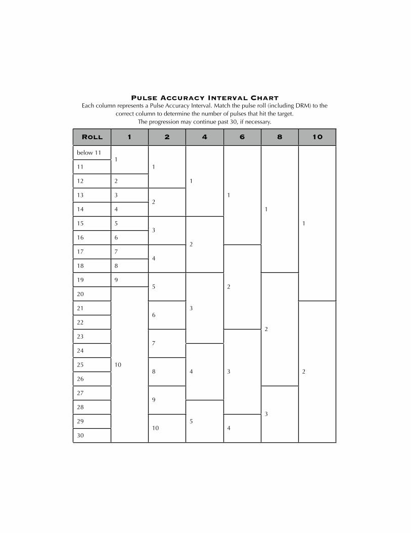
Pulse Accuracy Interval ChartEach column represents a Pulse Accuracy Interval. Match the pulse roll (including DRM) to the
correct column to determine the number of pulses that hit the target.The progression may continue past 30, if necessary.
Pulse Accuracy Interval ChartEach column represents a Pulse Accuracy Interval. Match the pulse roll (including DRM) to the
correct column to determine the number of pulses that hit the target.The progression may continue past 30, if necessary.
Pulse Accuracy Interval ChartEach column represents a Pulse Accuracy Interval. Match the pulse roll (including DRM) to the
correct column to determine the number of pulses that hit the target.The progression may continue past 30, if necessary.
Pulse Accuracy Interval ChartEach column represents a Pulse Accuracy Interval. Match the pulse roll (including DRM) to the
correct column to determine the number of pulses that hit the target.The progression may continue past 30, if necessary.
Pulse Accuracy Interval ChartEach column represents a Pulse Accuracy Interval. Match the pulse roll (including DRM) to the
correct column to determine the number of pulses that hit the target.The progression may continue past 30, if necessary.
Pulse Accuracy Interval ChartEach column represents a Pulse Accuracy Interval. Match the pulse roll (including DRM) to the
correct column to determine the number of pulses that hit the target.The progression may continue past 30, if necessary.
Pulse Accuracy Interval ChartEach column represents a Pulse Accuracy Interval. Match the pulse roll (including DRM) to the
correct column to determine the number of pulses that hit the target.The progression may continue past 30, if necessary.
Roll 1 2 4 6 8 10
below 111
1
1
1
1
1
111
1
1
1
1
1
12 2
1
1
1
1
1
13 32
1
1
1
1
14 42
1
1
1
115 53
2
1
1
1
16 63
2
1
1
1
17 74
2
2
1
1
18 84
2
2
1
1
19 95
3
2
2
1
20
10
5
3
2
2
1
21
10
63
2
2
2
22
10
63
2
2
2
23
10
7
3
3
2
2
24
10
7
4 3
2
225 10
8 4 3
2
226
108 4 3
2
2
27
10
9
4 3
3
2
28
10
9
5
3
3
2
29
10
105
4
3
2
30
10
105
4
3
2
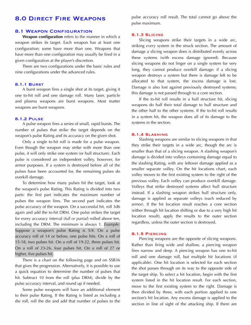
8.0 Direct Fire Weapons
8.1 Weapon ConfigurationWeapon configuration refers to the manner in which a
weapon strikes its target. Each weapon has at least one
configuration; some have more than one. Weapons that have more than one configuration may usually be fired in a
given configuration at the player’s discretion.There are two configurations under the basic rules and
nine configurations under the advanced rules.
8.1.1 BurstA burst weapon fires a single shot at its target, giving it
one to-hit roll and one damage roll. Many laser, particle and plasma weapons are burst weapons. Most matter
weapons are burst weapons.
8.1.2 PulseA pulse weapon fires a series of small, rapid bursts. The
number of pulses that strike the target depends on the weapon’s pulse Rating and its accuracy on the given shot.
Only a single to-hit roll is made for a pulse weapon. Even though the weapon may strike with more than one pulse, it will only strike one system (or hull structure). Each
pulse is considered an independent volley, however, for armor purposes. If a system is destroyed before all of the
pulses have been accounted for, the remaining pulses do overkill damage.
To determine how many pulses hit the target, look at
the weapon’s pulse Rating. This Rating is divided into two parts: the first part indicates the maximum number of
pulses the weapon fires. The second part indicates the pulse accuracy of the weapon. On a successful hit, roll 3d6 again and add the to-hit DRM. One pulse strikes the target
for every accuracy interval (full or partial) rolled above ten, including the DRM. The minimum is always 1. Example:
Suppose a weapon’s pulse Rating is 5/4. On a pulse accuracy roll of 14 or below, one pulse hits. On a roll of 15-18, two pulses hit. On a roll of 19-22, three pulses hit.
On a roll of 23-26, four pulses hit. On a roll of 27 or higher, five pulses hit.
There is a chart on the following page and on SSB36 that gives the progression. Alternatively, it is possible to use a quick equation to determine the number of pulses that
hit. Subtract 10 from the roll (plus DRM), divide by the pulse accuracy interval, and round up if needed.
Some pulse weapons will have an additional element to their pulse Rating. If the Rating is listed as including a die roll, roll the die and add that number of pulses to the
pulse accuracy roll result. The total cannot go above the
pulse maximum.
8.1.3 SlicingSlicing weapons strike their targets in a wide arc,
striking every system in the struck section. The amount of damage a slicing weapon does is distributed evenly across
these systems (with excess damage ignored). Because slicing weapons do not linger on a single system for very
long, they cannot produce overkill damage: if a slicing weapon destroys a system but there is damage left to be allocated to that system, the excess damage is lost.
Damage is also lost against previously destroyed systems; this damage is not passed through to a core section.
If the to-hit roll results in a hull structure hit, slicing weapons do half their total damage to hull structure and the other half to the other systems. If the to-hit roll results
in a system hit, the weapon does all of its damage to the systems in the section.
8.1.4 SlashingSlashing weapons are similar to slicing weapons in that
they strike their targets in a wide arc, though the arc is
smaller than that of a slicing weapon. A slashing weapon’s damage is divided into volleys containing damage equal to
the slashing Rating, with any leftover damage applied as a smaller separate volley. On the hit locations chart, each volley moves to the first existing system to the right of the
previous volley. Each volley can produce overkill damage. Volleys that strike destroyed systems affect hull structure
instead. If a slashing weapon strikes hull structure only, damage is applied as separate volleys (each reduced by armor). If the hit location result reaches a core section
(either through hit location shifting or due to a very high hit location result), apply the results to the outer section
regardless, unless the outer section is destroyed.
8.1.5 PiercingPiercing weapons are the opposite of slicing weapons.
Rather than firing wide and shallow, a piercing weapon fires narrow and deep. A piercing weapon has one to-hit
roll and one damage roll, but multiple hit locations (if applicable). One hit location is selected for each section the shot passes through on its way to the opposite side of
the target ship. To select a hit location, begin with the first system listed in the hit location result. For each section,
move to the first existing system to the right. Damage is then divided by three, with each portion applied to one section’s hit location. Any excess damage is applied to the
section in line of sight of the attacking ship. If there are

fewer than three sections being hit (either due to the ship’s
hull type or the earlier destruction of a section), the damage applied to the “missing” sections is lost. If there
are more than three sections within the path of the piercing weapon, the weapon only penetrates the nearest three sections.
The resulting hits are treated as individual volleys. Piercing weapons do not cause overkill damage; they are
too tightly focused. Overkill damage is lost. If one of the struck ship sections is already destroyed, the damage applied to that section is lost. If the weapon strikes an
existing but destroyed ship system, the damage to that system is lost (not applied to hull structure).
Piercing weapons cannot be used against fighters or shuttles.
To use a piercing weapon, the ship must assign two
EW points to the weapon. These EW points must not have been allocated during the Electronic Warfare Phase; they
cannot be used for ECM or EW shrouds. If the EW points are not assigned, the piercing weapon cannot be fired on the target.
8.1.6 FlareFlare weapons do not penetrate very deeply, but they
affect multiple systems at once. A flare weapon cannot produce overkill damage. Instead, excess damage is applied to the first existing, intact system to the right of the
initial hit on the hit locations chart; the damage is considered a separate volley. This process continues until
there is no excess damage remaining.If a flare hits hull structure, treat the hit as a burst
configuration.
If a flare’s hit location would produce core damage (by hitting a destroyed system) and there are still intact systems
and structure in the hit section, shift the hit location (according to the normal rules) until an intact system is hit. If no intact system is available, the flare hits hull structure.
Only once there are no systems or structure points left on the struck side will a flare be able to penetrate to the core
of a ship.
8.1.7 EnvelopingEnveloping weapons are expensive to build and
activate. Enveloping weapons are the only configuration that can directly strike targets on sides other than the one
in line of sight. Enveloping weapons are treated as slicing weapons that affect every facing ship section (that is, excluding the core sections). Damage is divided evenly
among all sections, with excess damage lost.
Defensive Fire cannot be used against enveloping
weapons.
8.1.8 WaveWave-based weapons are capable of striking any and
all ships within its range and firing arc. Beginning with the attacker’s hex and moving outward along the firing arc, the
attacker rolls to hit once for each ship (friend or foe) in the weapon’s path. (Note that, as with other direct fire
weapons, the Range DRM will worsen as the distance from the firing unit increases.) This continues for each hex distance until the attacker’s modified to-hit roll results in a
miss, or the weapon’s maximum range is reached.If the weapon misses at a given range and there are
other units at the same range that have not yet been checked for a hit, the attacker may roll to hit against those units (but not against any units at a greater distance from
the firing unit).For the purposes of damage allocation, treat the wave
weapon as a slicing weapon against each ship that it successfully hits.
Defensive Fire cannot be used against wave weapons.
8.1.9 TrackingTracking weapons fire over multiple turns. In order for
a tracking weapon to fire in its tracking configuration, it must be armed at double power for the duration of its attack. This extra power must have been assigned during
the Power Allocation Phase.Roll to-hit as normal. To determine the number of turns
the weapon will hit its target (assuming the weapon maintains line of sight, firing arc and viable range), roll 3d6 again and add the to-hit DRM.
Consult the following chart:
Roll Result Number of Turns
11-13 1
14-16 2
17-19 3
20+ 4
If the weapon’s tracking Rating is lower than the
resulting number of turns, use the tracking Rating.The tracking weapon will stop firing if line of sight is
broken or the target ship moves out of the weapon’s firing

arc. The weapon will also stop firing if it is unpowered or
takes any damage during its firing period.For all other purposes a tracking weapon is considered
a burst weapon unless otherwise specified. Damage is rolled on each turn that the tracking weapon hits its target, using the hit location result from the initial to-hit roll. If the
result was a system hit, move one column to the right on each turn.
Tracking weapons may be fired as standard weapons (using a burst configuration unless otherwise specified), but do not benefit from multi-turn tracking. Tracking weapons
cannot track in a wave configuration.
8.2 Weapon TechnologiesEvery weapon system is based on a single weapon
technology. The standard rules include a “default” set of seven options (matter, laser, particle, radiation,
electromagnetic, plasma and gravitic). However, it is possible to create new technologies if these seven are not
appropriate (see Rule 17.5).The first three technologies are available under the
basic rules. The remaining four are found in the advanced
rules.
8.2.1 MatterMatter weapons fire material projectiles of various
sizes. Matter weapons that fire small projectiles are usually treated as pulse or flare weapons. Larger weapons that fire
large-caliber shells usually use the rules for burst weapons.Special Rules: Matter weapons ignore armor, but do
not cause overkill. Matter weapons cannot be used for Defensive Fire except with the addition of certain enhancements.
8.2.2 LaserLaser weapons fire bursts of focused photons.
Special Rules: Because laser weapons take a moment to charge, they cannot be used as Defensive Fire weapons and rate of fire construction costs for lasers are doubled.
8.2.3 ParticleParticle weapons fire dense bursts of atoms at sub-light
speeds; they are frequently called “atom lasers.” Because they are slower (but more agile) than true lasers, they can be intercepted by Defensive Fire and can be used as
Defensive Fire weapons.Special Rules: Particle weapons do not have special
rules.
8.2.4 RadiationRadiation-based weapons (sometimes called “nuclear
weapons”) are highly effective against living crews (and living ships). They are most commonly configured as flare,
enveloping or wave weapons.Some missiles are fitted with nuclear warheads.
Contrary to popular belief, a nuclear warhead explosion in
space does not produce a massive fireball like the mushroom clouds of a thermonuclear detonation in
atmosphere. (The firestorm of a nuclear explosion requires air to fuel it.) However, a space-bound guided nuclear weapon can still cause significant radiation damage to its
targets.Special Rules: Radiation weapons do not have special
rules.
8.2.5 ElectromagneticEM weapons create strong discharges of electricity—
essentially bolts of lightning over long distances. Although the physical damage caused by EM is relatively low,
numerous special effects are possible with these weapons.Special Rules: EM weapons may only use d4 dice for
damage rolls. EM weapons treat EM shields as if the shields
were at half strength.
8.2.6 PlasmaPlasma weapons rely on superheating quarks and
gluons and then aiming them at a target. Most torpedoes are treated as plasma weapons.
Special Rules: Plasma weapons (not including most plasma-based torpedoes) tend to have very short ranges,
and their damage decreases the farther they must travel to the target. However, they inflict double damage to hull structure. They also treat armor as having half its value
(rounded up). A plasma weapon’s Rating indicates how much damage is lost per hex.
8.2.7 GraviticGravitic weapons manipulate the molecules of their
targets by forcing them to bend and distort. Some gravitic
weapons are able to attract or repel entire ships.Special Rules: Many gravitic weapons can be used to
produce shields, in addition to their use in offensive and defensive fire. A gravitic weapon capable of functioning as a shield may not be used as a weapon in the same turn. A
gravitic weapon being used for Emergency Defensive Fire can be converted to shield mode (if capable) in exchange
for incurring a point of damage.Gravitic weapons treat Gravitic shields as if the shields
were at half strength.
9.0 Guided WeaponsGuided weapons are launched prior to movement,
during the Preliminary Actions Step. A guided weapon travels more slowly than other weapons, under its own
power.In order to launch a guided weapon, a unit’s guided
weapon launcher (the weapon rack) must meet all of the
requirements listed in Rule 7.1 at the time of launch. For missile systems, the weapon rack must have missiles
remaining and available to fire.A unit that has fired guided weapons is not required to
maintain these requirements past the Preliminary Actions
Step of that turn. A guided weapon will still be able to roll to hit even if the firing unit has pivoted away from the
target, bringing the target out of arc of the firing rack. However, during the Weapons Fire Step, the guided weapon itself must have line of sight to its target.
Missiles do not use the launching ship’s target amplification: the missiles themselves receive a flat +2 EW
target amplification from their own sensors. (This can be increased using a special missile enhancement.) The firing ship does not need to be locked onto its target to fire a
missile. Torpedoes use the launching ship’s EW target amplification, and require a lock-on to fire.
There are two additional requirements for guided weapons, both involving range. During the Preliminary Actions Step, the target must be within the launch range of
the firing unit’s guided weapon. If it is not, the weapon may not fire at that target. During the Weapons Fire Step, the
target must be within the maximum range of the guided weapon. If not, it deactivates and does not strike its target.
9.1 Guided Weapon Fire ProcedureWhen a guided weapon is launched at the appropriate
point in the turn, place a guided weapon marker on the
firing unit’s hex. This represents the launch point of that guided weapon.
At the Guided Weapons Phase of the Weapons Fire
Step, check the necessary conditions for the guided weapon to attempt to hit:
• The target’s counter is within the maximum range of the guided weapon’s counter
• The target is within line of sight of the guided weapon.
If both conditions are true, the weapon may roll to hit. If one or both conditions are false, the guided weapon fails to reach its target. If the weapon does not have line of sight
because it is blocked by an enemy unit, the weapon will change targets and lock onto the blocking unit instead. If
this occurs, for the purposes of hit and damage
determination treat the guided weapon as if the new target
were the original target.
9.2 Guided Weapon Types
9.2.1 Missile RacksMissile weapon systems are called missile racks. Each
rack may carry a limited number of missiles (usually 20),
which are fed from the magazine into the missile launcher one at a time. It is possible to mix the types of missiles
found in a rack, and any missile in the rack may be fired in any sequence. If a reload rack is available, missiles may be offloaded from the magazine to the reload rack.
9.2.2 TorpedoesTorpedoes are ad hoc guided weapons: the
ammunition for a single shot is created by the system when the weapon is fired. For this reason, torpedoes do not have racks (and do not use reload racks). The main advantage of
this feature is that a torpedo system will never run out of ammunition. The main drawback is that the torpedo
system’s weapons are of a fixed type: alternative torpedoes may not be “loaded” onto the system the way missiles can be loaded into a missile rack.
9.2.3 DronesDrones are low-speed missiles. Instead of striking on
the same turn they are fired, they travel across the map, taking the shortest route to their targets. Drones have a speed Rating that determines the maximum number of
hexes (and levels, if three-dimensional movement is used) they may travel each turn. Drones move at the end of the
Movement Step. They can move in any direction, and it is not necessary to keep track of a drone’s facing.
A drone will continue to move toward its target on
each turn, until it has expended its maximum range. If the drone enters its target’s hex during its movement, it rolls to
hit like a guided weapon.Because of their slow speed, drones do not need to
maintain line of sight to their targets after they have been
launched; they do not attempt to target new ships if line of sight is lost. If a drone loses line of sight to its target, it will
continue to move toward the hex in which its target last “appeared” to its tracking computer. If it does not regain line of sight by the time it reaches that hex, it will
deactivate and fail to detonate.
9.2.3.1 Weapon AttachmentsSome drones are built with direct fire weapon
attachments. These weapons are standard small vessel

weapons and are powered by the drone’s own power
source. They are always mounted as Turrets and are treated as being both on dorsal and keel sides of the drone. That is,
they can fire out of every facing.Drone weapon attachments may be fired at any target,
not only the target of the drone itself. Unlike small vessel
weapons, drone weapon attachments are subject to ECM. Against a drone’s target, a weapon attachment has an target
Amplification of +1. Against all other targets it has no Amplification.
Weapon attachments are fired after small vessel direct
fire. On the turn after a weapon attachment has fired, any weapon targeting the drone gains a +1 to hit, per shot fired.
9.2.4 Reload RacksSome ships are equipped with missile reload racks. A
reload rack can supply any missile rack on the ship. Reload rack operations occur during Final Actions.
A reload rack will always load missiles from the top of its magazine. It may also unload missiles from a missile
rack, placing the unloaded missile at the bottom of its magazine.
Reload rack loading and unloading is limited by the
number of operations it may perform each turn.
10.0 Stationary WeaponsSome units are capable of deploying stationary
weapons. This category includes mines, weapon platforms and ESS beacons, among other devices. There are two ways
that stationary weapons may be deployed, depending on the system (called a drum) that releases them: ejected or deposited. Both deployments occur during the Final Action
Step of the turn, but must be announced during the Preliminary Actions step. Direction and distance do not
have to be announced, only the fact that the weapon is being deployed. Once deployed, a stationary weapon will become “live” (activated and powered) on the following
turn.An ejected stationary weapon is fired from its weapon
drum through the drum’s firing arc. Once fired, it will travel to up to its maximum range, at the player’s discretion, then fire small stabilizing thrusters (useful only for keeping the
weapon in position). The ejecting unit must have line of sight to the location on the map where the weapon is being
deployed. Place the appropriate stationary weapon counter on the map at that point.
A deposited stationary weapon is fired from its weapon
drum directly onto the center of the firing unit’s counter, where it remains. A depositing drum has no firing arc and
cannot propel the weapon.Drums carry a limited number of munitions, usually
between 1 and 5, although the drums aboard minelayer
ships tend to be considerably larger.
10.1 MinesMines detonate when enemy units come within range
of their rudimentary sensor suite. When playing with the three-dimensional movement option, players should keep
in mind that creating barriers with minefields is significantly more time-consuming and requires
considerably more mines. Occasionally, superior fleet commanders will find ways to herd enemy ships into a minefield by knocking out the thrusters needed to evade
the mines as the ships are chased into the seeded region of space.
Mines activate during the Movement Step, as soon as they are triggered by an enemy’s presence.
10.1.1 Proximity MinesA proximity mine detonates as soon as an enemy target
enters its range, which by default is 1 hex. All proximity
mines do damage as wave weapons with a maximum range of 1 hex. Defensive Fire cannot be used against proximity mines.

If an enemy ship passes within range of a proximity
mine during its movement, the mine detonates and the attack is resolved immediately, before the ship completes
its movement. Determine which section is struck based on the ship’s approach.
10.1.2 Swarm MinesA swarm mine activates as soon as an enemy target
enters its range, which by default is 2 hexes. Upon
activation, a swarm mine becomes a cluster of guided weapons: it tracks its target and detonates on impact. All swarm mines do damage as pulse weapons.
Any Defensive Fire that can be used against guided weapons may be used against swarm mines. Swarm mine
attacks are resolved during the guided weapons phase and are treated as guided weapons fired from the hex into which the swarm mine was deployed. They have unlimited
range once they begin to swarm, and are not affected by any range penalties.
10.2 Micro-PlatformsMicro-platforms are treated like weapon platforms
(Rule 10.4) with a single weapon installed. A micro-
platform activates as soon as an enemy target enters its range, which by default is 2 hexes. The micro-platform
resolves its fire during the Weapons Fire Step, along with weapon platforms.
After a micro-platform has fired once, its weapon
system’s power source expires and it is destroyed.Defenders may use any Defensive Fire that can be used
against the weapon installed on the micro-platform.
10.3 ESS BeaconsESS beacons are mine-sized devices with somewhat
more complex sensor suites and ESS functions. They last for a number of turns equal to the power requirement of their
ESS system.
10.4 Weapon PlatformsWeapon platforms are independent, computer-
controlled units that do not move but are able to fire like ships. Typically, they have two or three weapons mounted
on turrets. Weapon platforms will fire at any and all possible enemy targets.
10.5 Detecting and TargetingWeapon platforms are large enough that they do not
need to be detected before they can be targeted. ESS
beacons, because they are constantly emitting signals, also do not need to be detected before targeting.
All types of mines are too small to be detected
automatically. To attempt to detect a mine, a ship must activate an EW or ESS shroud and select a hex within the
shroud’s range. The base chance to detect a mine within the hex (if there is one present) is 6 if using an EW shroud. The base chance is 9 if using an ESS shroud. Roll 3d6. On
a roll equal to or less than the chance to detect, any mine(s) in the target hex are detected.
Once a mine is detected, treat its silhouette Rating and total section count as zero. They cannot use ECM (not even the ESS beacons) or DF of any kind.
11.0 Defensive SystemsA ship’s defensive systems give modifiers to an
incoming weapon’s chance to hit.
11.1 Defensive FireDefensive Fire, or DF, is weapons fire directed at
incoming attacks. The energy or material of most types of weapons fire can be deflected, diminished or absorbed by
Defensive Fire. Lasers are the major exception: they cannot be intercepted by Defensive Fire, and they cannot be used
for Defensive Fire.When an attack is made against a player’s unit, s/he
may attempt to use one or more weapons to reduce the
enemy’s chance to hit a vital location by deflecting the incoming fire. In order to use a given weapon, all of the
following criteria must be met:
• The attacking unit is within the defending weapon’s firing arc.
• The defending weapon has not and will not fire offensively on the current turn.
• The defending weapon is activated and able to fire.• The defending weapon has a Rating that permits it to
provide Defensive Fire.• The attacking weapon is of a type that can be
intercepted. (Lasers are the major exception.)• The defending weapon has not fired defensively on
the current turn.• The defending weapon’s Speed Rating is equal to or
greater than the attacking weapon’s Speed Rating.There are three types of Defensive Fire: standard, ad
hoc and emergency. Every weapon will have a three-part
Defensive Fire Rating corresponding to each of these types.
11.1.1 Standard Defensive FireStandard Defensive Fire is available to weapons that
are designed specifically to act as DF interceptors. Most weapons have an SDF Rating of zero, which means they
cannot be used for Standard Defensive Fire.If a weapon can be used for SDF, apply its SDF Rating
as a negative modifier to the enemy’s chance to hit. Any number of SDF weapons may be applied as negative modifiers, as long as each one meets the criteria listed
above.Some SDF weapons can be used offensively as well.
During the Fire Determination Phase, after all players have announced their attacks and DF, SDF weapons that were declared as offensive may be switched to their SDF modes
freely. This switch must be declared immediately.
11.1.2 Ad Hoc Defensive FireAd Hoc Defensive Fire (AHDF) is available to many
weapons that are not designed to act as interceptors. In
most cases, a weapon’s AHDF Rating will be lower than a
similar interceptor’s SDF Rating.In addition to the standard criteria, two additional
restrictions limit the usefulness of Ad Hoc Defensive Fire. First, any weapon that is going to be used for AHDF must be declared as such during the Fire Determination Phase.
AHDF weapons being fired offensively may not be switched to AHDF after declaration. Second, while any
number of weapons may be used for AHDF, the total modifier from AHDF against a single incoming attack cannot exceed four times the lowest AHDF Rating among
those weapons being used to deflect the attack.
11.1.3 Emergency Defensive FireEmergency Defensive Fire is similar to Ad Hoc
Defensive Fire in that it is used by weapons that do not have SDF Ratings. Most weapons that have AHDF Ratings
will have EDF Ratings as well.If an AHDF weapon is able to defend against an
incoming attack but was declared to be in offensive mode during the Fire Determination Phase, it may attempt Emergency Defensive Fire. The standard criteria apply,
including the requirement that the weapon not be fired offensively on the same turn. The total modifier from EDF
cannot exceed four times the lowest EDF Rating in the group.
EDF is possible even if the weapon is currently being
armed and is not yet able to fire under normal conditions. If an unarmed weapon uses EDF, on the next turn it is
forced into a cooldown period equal to the length of its arming cycle (whether or not the weapon normally requires cooldown). A weapon that is deactivated or in cooldown
mode may not be used for EDF.Emergency Defensive Fire is stressful on the weapon
system. Every EDF weapon involved in defense against the attack automatically suffers one point of damage (ignoring armor). Fighters and shuttles that use EDF suffer the
damage directly (to structure).
11.1.4 Weapon Speed RatingEvery weapon technology type has a Speed Rating,
which indicates how quickly the weapon’s shot reaches its target after it has been fired. Guided weapons are the
slowest; laser weapons are the fastest. A weapon may not fire defensively against weapon technologies that are faster
than its own Speed Rating. Note that Speed Ratings are not related to Rate of Fire, which is a separate element.
11.1.5 Ablative Defensive FireSome weapons will be capable of ablative defensive
fire. This form of defensive fire (available only to SDF and AHDF) does not reduce the chance to hit. Rather, if an
incoming direct fire weapon successfully strikes, all engaged ablative DF weapons reduce the resulting damage by ten percent of the total damage rolled per –1 of DF,
rounded up.Example: A weapon with –2 SDF against a weapon
doing 12 points of damage will reduce the damage by 4 points: 10% of 12 is 1.2, rounded up to 2. Since the SDF is –2, reduction is twice the 2 points, for a total of 4 points of
reduction. The resulting damage is 8 points.Against guided weapons, ablative defensive fire
functions as normal defensive fire (to-hit DRM penalty).
11.1.6 Guided Weapon InterceptIn addition to normal defensive fire (SDF, AHDF or
EDF) against guided weapons, it is possible to attempt to shoot down (intercept) the missile or torpedo before it
strikes its target. This is attempted during the Guided Weapons Phase, prior to regular direct fire attacks.
To make the attempt, the guided weapon’s launch hex
must be within the firing arc (and range) of the defending weapon. The weapon must be a direct fire system and it
must be able to fire on the current turn. Any unit (not only the target) may attempt to intercept any missile or torpedo,
as long as its weapon fits the requirements. The intercept attempt must be declared during the Fire Determination Phase, and is completed during the Guided Weapons
Phase. The weapon may not target any other unit during the current turn.
Treat the guided weapon as having a Silhouette of zero and a total section count of zero. Apply any EW amplification (or the missile’s built-in EW) as a negative
DRM, as well as any Accuracy bonus that the guided weapon receives from its launcher. The attacking unit does
not lend its ECM to the guided weapon. The intercepting unit may use any available EW amplification, and will suffer the doubled range penalty if its EW shroud does not
extend to the guided weapon’s launch hex. For the purposes of determining the range penalty, use a range of 4
hexes or the range to the launch hex, whichever is lower.A weapon with a RoF of 2+0 or greater may attempt
more than one intercept. On the second attempt, treat the range to the guided weapon as 2 hexes (or less, if the launch hex is nearer than 2 hexes). On a third or fourth
attempt, treat the range as 1 hex.If the intercept is successful, the guided weapon is
destroyed before it strikes its intended target. If the attack is
unsuccessful, the guided weapon may then roll to hit its
target.
11.1.6.1 Weapon RestrictionsIf a weapon is being used for normal Defensive Fire, it
cannot attempt an intercept. If a weapon is unable to target small vessels, it may not target a guided weapon. Wave-
configured weapons may not attempt intercepts. Weapons that do no damage may not attempt intercepts.
11.1.6.2 Intercepting DronesDrones may be shot down at any point during their
travel to the target. Treat the drone as a standard guided
weapon, except for its range: use its current distance from the intercepting weapon.
11.1.7 Screening Defensive FireWeapons belonging to units that are not the current
target may be used to defend against incoming attacks
(against the current target) under certain circumstances. This is called screening.
In order for a unit to use one or more of its weapons as defensive fire to protect another unit, the following conditions must be met:
• The weapon must have an SDF Rating.• The weapon must be assigned to SDF on the current
turn (and must be allocated to the correct incoming attack during fire determination).
• The range penalty of the defending weapon (between the defending unit and the targeted unit) must be no greater than –1 for each point of weapon Speed (e.g., a Plasma weapon, which has a Speed of 2, may have a range penalty up to –2).
• The weapon’s firing arc must include the target unit or the attacking unit (or both).
• The range between the defending unit and the attacking unit must be less than the range between the target unit and the attacking unit. (That is, the screening defender must be closer to the attacker than the target.)
Screening DF is resolved according to the normal rules for Defensive Fire, at the time that the attack is resolved. Screening weapons may implement ablative DF if the
option is available to them.Note that the range penalty check has no bearing on
the effectiveness of the screening DF. It is only used to determine whether or not the weapon is permitted to screen for the target unit.

11.1.7.1 Guardian EnhancementThe Guardian enhancement increases the maximum
range penalty per point of weapon Speed to –2.
11.2 ShieldsShields offer two kinds of protection against incoming
fire. Some shield types only use one kind; others use both.The first kind of protection is active, generating a
negative modifier to the enemy’s to-hit roll. This is called deflection. The second kind of protection is passive: once
an opponent has successfully rolled to hit, the incoming shot will strike any applicable shield before it can reach the ship itself. This is called absorption.
Shields come in three different configurations: arc, point defense and encapsulating. Arc shields protect
individual sections. Point defense shields protect individual systems. Encapsulating shields protect the entire ship, in all directions.
Shields require considerable amounts of power. Some shields can offer partial protection while under partial
power; others must be fully powered in order to offer any protection.
11.2.1 Deflection ShieldsEvery deflection shield has a deflection Rating. When
the shield is powered, it applies its deflection Rating
against the to-hit chance of incoming fire (as a negative DRM).
If a deflection shield is capable of and currently
operating under partial power, it will provide only half of its Rating as a modifier (rounded down).
11.2.2 Absorption ShieldsAbsorption shields function like armor. If an incoming
shot successfully hits the section or facing that an
absorption shield is protecting, reduce the total damage of each volley by an amount equal to the shield’s absorption
Rating.If an absorption shield is capable of and currently
operating under partial power, it will reduce damage by
only half of its Rating.
11.2.2.1 Buffering ShieldsA subtype of the absorption shield exists, called a
buffering shield. Buffering shields absorb damage like standard absorption shields, but lose an amount of
protection equal to the amount of damage absorbed. Buffering shields recharge over time, returning eventually
to their maximum strength.As with standard absorption shields, against weapons
with the Anti-Shield enhancement, treat the absorption
Rating at half its current strength. A buffering shield cannot
lose more than half of its current strength to an Anti-Shield weapon.
Example: A weapon with the Anti-Shield enhancement does 50 points of damage against a buffering shield that currently holds 80 absorption points. 40 points of damage
are absorbed by the shield (reducing it to 40 points) and 10 points of damage pass through the shield and strike the
unit.
11.2.3 Hybrid ShieldsSome shields are able to provide both deflection and
absorption effects. These shields will have a dual Rating, with the deflection Rating appearing before the slash.
Incoming fire will be adjusted by both Ratings (to-hit chance and volley damage).
Some hybrid shields can shift their effectiveness
between the two functions. If a hybrid shield is capable of doing this, its Rating will appear as a single number. The
player can assign the points of the Rating to deflection and absorption as s/he chooses during the Power Allocation step. This assignment cannot be changed until the next
turn.A few high technology hybrid shields can shift point
assignments more rapidly, and do not need to wait until Power Allocation. Point assignment is selected after all weapons fire has been declared but before any rolls are
resolved. Once the points are assigned (at the beginning of the Weapons Fire Step) they cannot be changed until the
next Weapons Fire Step.
11.2.4 Arc ShieldsArc shields protect against fire striking the section in
which the arc shield resides. Arc shields cannot protect core sections. Arc shields can only protect a single section.
11.2.5 Point Defense ShieldsPoint defense shields are small, low-powered shields
that protect individual ship systems. Point defense shields
are always absorption shields; they are never capable of deflection. There are two types of point defense shields:
stationary and roaming.Stationary point defense shields are assigned to a
single ship system. They will not have any defensive effect
on any system other than the one to which they have been assigned. Stationary point defense shields are able to
protect core systems under all circumstances.Roaming point defense shields are not assigned to
individual ship systems. Instead, they travel across a given
ship section to protect all systems in that section. Once an

incoming shot has rolled for hit location, the defender rolls
3d6. If this roll is equal to or less than the roaming point defense shield’s speed Rating, it successfully travels to the
hit system and applies its absoption Rating. If the roll is higher than the speed Rating, the incoming shot strikes the system without interference from the shield.
Although point defense shields require very little power, their small size allows for concentrated effect: they
tend to be far more effective than larger arc shields. As with arc shields, they may not protect systems in core sections.
11.2.6 Encapsulating ShieldsEncapsulating shields require considerable amounts of
power, but protect the ship from fire incoming from any
direction: they protect all outer sections at once.Encapsulating shields do not protect core sections.
11.2.7 Layering ShieldsMost shields cannot be used in conjunction with other
shields. Only one shield will deflect or absorb any given
incoming shot. If more than one shield is capable of defending against the shot, the defending player must choose which shield does so.
The defending player may select which shield is to be used on a shot-by-shot basis; s/he is not required to declare
which shield is in effect prior to weapons fire declaration.Some shields can be enhanced to work together with
other shields. If all shields capable of defense against a shot
are enhanced in this way, then all of these shields act against the incoming shot. If even one of the shields is not
enhanced to work in tandem, the player must select only one of the (non-enhanced) shields to function against the attack.
11.2.8 Shield Over-Loading (Advanced Rule)
Some shields may be over-loaded to provide additional
protection against incoming attacks. If a ship’s shield can be over-loaded, applying 1 point of additional power during Power Allocation will increase its Ratings by 50%
(rounded down) for the current turn.
11.2.9 Shield-Related EffectsElectromagnetic weapons are especially effective
against EM shields, and Gravitic weapons likewise against Gravitic shields. When a weapon of the same type strikes a
shield, treat the shield as if it were at half strength (absorption and deflection Ratings are at 1/2 value). This
effect is similar to but not identical with the Anti-Shield enhancement.
11.3 Collector PanelsCollector panels are a form of power plant technology
(see Rule 3.1.5). Although most collector panels generate
power by sifting through ambient energies around the ship, some panels use the energy generated by incoming weapon strikes.
Each time a weapon strikes the section in which a collector panel is installed, one point of damage (after
shields) is diverted into the panel. The panel must then transfer this point of energy directly into a battery.
If no batteries are available to receive the energy, or all
batteries are currently full, the collector panel disengages and does not divert the weapon damage.
Collector panels cannot divert weapon damage that would otherwise strike the panel.
11.4 ArmorUnlike other systems, sectional armor does not appear
on the hit locations chart. Instead, it is always the first
system struck by incoming fire (after shields have applied their defensive capabilities).
There are three kinds of armor: standard, ablative and
adaptive. In addition, specialized armor is effective against certain weapon technologies. Standard armor works
according to the basic rules for armor.
11.4.1 Ablative ArmorThe effectiveness of ablative armor is reduced by one
point each time it is hit. Once the armor’s Rating has dropped to zero, the system is destroyed and no longer
protects the section.Weapons that affect armor in special ways affect
ablative armor in the same ways. The 1-point reduction in
armor effectiveness is not altered by such weapons.Some but not all forms of ablative armor can be
repaired. Because ablative armor does not use structure points, repair systems that are used to restore structure have no effect on ablative armor.
Ablative armor protects only the section in which it has been installed. It can be installed in core sections.
Individual system armor works as normal: incoming fire must penetrate both types of armor before it can affect the underlying system.
11.4.2 Adaptive ArmorThe effectiveness of adaptive armor changes based on
the amount and type of damage the ship receives during battle.
Each weapon technology (matter, plasma, etc.) is listed
on the adaptive armor Control Panel. Each time a weapon strikes the section being protected by the adaptive armor
and does at least 1 point of damage, one point of defense is added to that weapon technology’s row on the Control Panel. If a shield absorbs all of an attack’s damage, the
adaptive armor does not gain a point. If a system’s armor absorbs all of an attack’s damage, the adaptive armor will
still receive 1 defense point.The next time the section being protected by the
adaptive armor is struck with the same weapon technology,
the armor’s defense points against that technology are used as standard armor to mitigate the damage. After damage
has been reduced, the adaptive armor then gains another point of defense against that weapon technology. (Incoming shots are not mitigated by the point of defense
that they themselves give to the adaptive armor.)Adaptive armor points dissipate after a battle has
ended. In some scenarios a ship’s adaptive armor will enter battle with an existing configuration of defense points, but this is not a common occurrence.
Adaptive armor will have a maximum number of points that can be added to each technology and a
maximum number that can be used overall, listed as its Rating.
Some forms of adaptive armor are linked. Each linked
adaptive armor system will gain a point of defense whenever another adaptive armor system to which it is
linked receives a point.Collective adaptive armor is a more advanced form of
adaptive armor. Instead of receiving defense points against
specific weapon technologies, it receives all defense points into a general pool. The player may then assign these points
to individual weapon technologies as s/he chooses. Once a point has been assigned, it cannot be re-assigned until all of the adaptive armor’s points have dissipated (after battle).
When an adaptive armor point is generated, this information is made public during the next EW allocation
step. Players may choose to store the adaptive armor point rather than apply it as armor. If the armor point is stored, its existence is not made public. Once a stored point is
converted to actual adaptive armor, it cannot be removed except by the normal dissipation process.
Stealth adaptive armor can create adaptive armor points (or convert stored points) without revealing their existence to other ships.
Adaptive armor systems are limited in the total number of adaptive armor points they can produce, and in the
number of points that can be applied against each weapon technology.
If a ship with adaptive armor uses specialized armor,
the effects are the same as with other armor types. Each point of adaptive armor against a given attack is adjusted, if
applicable, by the relevant specialization.Individual weapons that ignore armor do not ignore
adaptive armor that has been assigned to the weapon’s
technology. However, if an entire weapon technology ignores armor, it also ignores adaptive armor unless that
armor has been specialized.
11.4.3 Specialized ArmorSome forms of armor are specialized. Specialized
armor is made from specific materials geared toward better defense against a specific weapon technology or
configuration.Armor specialization gives all armor in the ship a 50%
increase against the designated weapon type (rounded up).
Example: A ship with armor specialized against Radiation weapons is attacked by that technology. The
weapon strikes a system with 3 points of armor. Against this weapon, the armor is treated as having 5 points (50% of 3 points is 1.5, rounded up to 2).
Exceptions: Specialized armor that is effective against Matter weapons removes their ability to ignore armor. Treat
the armor Rating as 1/2 its normal value. Additional specializations function as per the above rule. Specialized armor effective against Plasma weapons removes their
ability to treat armor at 1/2 value. Use the armor’s true Rating instead.
11.5 Specialized DefensesThree defensive systems may be used against incoming
guided weapons: anti-missile rockets, chaff and flares. All
three may be used against missiles and torpedoes (despite the name of the first).
These specialized defenses are declared during the Fire Determination Phase and deployed during the Guided Weapons Phase.
11.5.1 Anti-Missile RocketsAnti-missile rocket systems (AMRS) fire small, high-
velocity rockets against incoming guided weapons. They may be used to defend the unit fielding the AMRS, or any other unit up to 4 hexes away.
The standard Rate of Fire of an AMRS is 1+0, but this may be increased during ship construction. The target
missile’s launch hex and the missile’s target must both be within the AMRS’s firing arc.
To determine whether the AMRS intercepts the missile or torpedo, roll to hit as if it were attempting a guided

weapon intercept (Rule 11.1.4). The AMRS has no range
DRM penalty, but it also may not use the fielding unit’s EW amplification as a DRM bonus. (The AMRS does not
require an EW shroud to operate.) The AMRS has an accuracy Rating of 0.
On a roll of 11 or higher (including DRM), the missile
or torpedo is destroyed.
11.5.2 ChaffChaff provides a DRM penalty to hit for any guided
weapon fired against any targets in the chaff-deploying unit’s hex. The standard DRM penalty is –1, but this may be
increased during ship construction.
11.5.3 FlaresFlares, like chaff, provide a DRM penalty to hit.
However, they are directed only against a single incoming weapon, and may be used to defend the unit fielding the
flare or any other unit up to 1 hex away.The standard DRM penalty is –2, but this may be
increased during ship construction.
12.0 Small Vessel Combat
12.1 Vanguards, Flights and Strike Forces
Fighters enter combat in groups of 3, 6 or 12. A group of 1-3 fighters is called a vanguard. A group of 4-6 fighters
is called a flight. A group of 7-12 fighters is called a strike force.
Fighter groups are treated as one unit for the purposes of ESS allocation, no matter how many fighters are in the group. They are also treated as one unit when enemies are
rolling to hit them.
12.1.1 Group Size ShiftsIf a fighter strike force drops to 6 ships, it becomes a
flight. If a flight drops to 3 ships, it becomes a vanguard.Two vanguards can combine to become a flight. Two
flights or four vanguards (or one flight and one vanguard) can combine to become a strike force.
12.1.2 ShuttlesShuttles are always represented individually on the
map, unlike fighters. However, for the purposes of the
rules, they are treated as vanguards with two fighters missing.
12.2 Fighter Group Weapons FireAll fighters of a single fighter group fire their weapons
simultaneously, at the same target. The fighter group rolls
once to hit for each weapon system.If the hit is successful, damage is rolled once and
applied a number of times equal to the number of fighters in the group. Damage is not combined into a single volley: each fighter fires its own volley.
6.2.1 Accuracy RatingsThe accuracy Ratings for fighter weapons assume that
they are being fired by a vanguard. If a weapon is being fired by a flight, the accuracy value goes up by 2. If a weapon is being fired by a strike force, the accuracy value
goes up by 4. Fighters may not have signed accuracy Ratings.
12.2.2 Linked WeaponsLinked weapons are partially controlled by a computer
network that links together the fighters of a single group. If
a fighter group of at least 3 fighters fires a linked weapon, its chance to hit gains a +2 bonus.

12.2.3 Guided WeaponsGuided weapons fire from fighter groups is handled
according to the rules for ships. Each shot rolls to hit separately, and damage is rolled independently for each
shot.
12.2.4 Defensive FireIf a fighter group’s target uses DF against its attack, the
DF value is modified based on the size of the group. Against fighter vanguards, the DF is not reduced. Against
fighter flights, the DF is reduced by 1. Against fighter strike forces, the DF is reduced by 2.
12.2.5 Formation FlyingAt the player’s discretion, a fighter group may fly in
formation if there are at least three fighters in the group. A
fighter group flying in formation gains +1 to its accuracy Rating. However, the value of Defensive Fire against the fighter group’s weapons increases by 1.
If a fighter group barnstorms a target while in formation, apply a –2 modifier to the barnstorming die roll.
12.3 Attacking Fighters/ShuttlesThe silhouette Rating of a fighter group is equal to one
third the total Mass of all fighters in the group, rounded
down (minimum zero). This Rating applies in all directions.Because fighters and shuttles do not have sections or
distinct systems, they react differently to damage. Slicing, slashing and piercing weapons cannot target fighters or shuttles unless otherwise specified on the weapon’s Control
Panel.
12.3.1 Fighter SelectionUnless otherwise specified, if a fighter group has at
least two fighters, the defending player chooses which fighter is struck by successful incoming fire. Some weapon
enhancements may permit the attacker to select a specific fighter target.
Wave-configured attacks hit every fighter in a group, with the damage divided among the fighters as they would be divided among ship sections (not entire ships).
Any weapon that normally strikes a single ship’s section (including weapons that fire multiple volleys that
strike the same section) will only target a single fighter. If that fighter is destroyed before all of the damage is applied, the remainder is lost. Weapons cannot do overkill damage
of any kind against fighters. Weapons that strike multiple ship sections will continue to hit fighters (as if each one
were a ship’s section) until all damage is applied or all fighters are destroyed.
12.3.2 ArmorFighters and shuttles have four armor Ratings: fore, aft,
port and starboard. Determine the direction of incoming
fire to identify which armor side is hit, using the section selection cube for 5 sections, according to the rules for starships.
12.3.3 Hull StructureIf any damage penetrates armor, it passes through to
the fighter or shuttle’s hull structure. If a fighter or shuttle’s hull structure is fully destroyed, the individual fighter or shuttle is destroyed.
12.4 HangarsShuttle and fighter bays, collectively called hangars,
carry a total Mass of shuttles or fighters equal to the amount of structure on the system. Each structure point represents one bay. Example: A fighter hangar with 6 bays
could carry 6 light fighters, 3 heavy fighters or 2 light fighters + 2 heavy fighters. If a hangar takes damage to its
structure, any fighter or shuttle in the destroyed bay(s) is destroyed along with the structure point. Fighters and shuttles with a Mass greater than 1 occupy more than one
bay, and are destroyed when any one of the bays in which they are housed is destroyed.
A hangar’s Rating indicates how many hangar operations it may perform each turn. There are four hangar operations:
• Launch one fighter/shuttle• Land one fighter/shuttle• Load one missile/mine onto fighter/shuttle• Unload one missile/mine from fighter/shuttle
12.4.1 Launch/LandA ship may only launch or receive a fighter or shuttle if
it has not pivoted, rolled or tumbled on the current turn. The maneuvers of the fighter or shuttle do not affect its ability to land.
Launched units appear in the same hex as the launching ship. If the hangar’s arc is fixed, the unit will
appear facing in the direction of the arc. If the arc is wider than a fixed arc, the unit may appear facing in any direction covered by the arc. The launched unit’s vector
(Speed and direction of travel) is the same as the launching ship’s vector, regardless of facing.
Landing units must end their movement in the same hex as the ship on which they are landing. They must be traveling at the same speed as the ship or greater, and they
must enter the hex through a facing accessible by the hangar’s arc.
If the landing unit’s speed is greater than the ship’s
speed by an amount equal to its thrust Rating or more, it receives one point of damage as it lands.
If a shuttle or fighter attempts to land in a hangar that is full, it and one of the units in the hanger are destroyed. If a shuttle or fighter attempts to land in a hangar that does not
carry units of its type, the landing unit is destroyed.
12.4.1.1 Initiative EffectsOn the turn after a shuttle/fighter launch, the launched
vessel’s initiative is increased by 10 and the launching unit’s initiative increases by 5.
12.4.2 External LaunchersExternal launchers may launch shuttles and fighters.
Most launchers may not receive landing units. No external launcher may load or unload ordnance.
External launchers cause no initiative penalty to the
launched unit or the launching ship. However, each time a launcher receives a unit (if it is capable of doing so), the
ship’s initiative increases by 3 on the subsequent turn.Shuttles and fighters may be transferred from a hangar
to an external launcher, but not from a launcher to a
hangar. This process requires 1 operation per vessel for three turns.
12.4.3 Hangar Launch TubesUnder normal circumstances, hangars may only be
mounted to an outer section (non-core). Hangar launch
tubes (HLTs) permit hangars to be placed in the unit’s interior, though there are tradeoffs.
HLTs must be located in an outer section nearest to the hangar to which it is attached. The arc of an HLT is always Fixed. Multiple launch tubes may be attached to a single
hangar.If all of a hangar’s launch tubes are destroyed, the
hangar may not launch or land any units. Each time a launch tube is used, the action counts as two hangar operations. Hangars that only permit one operation per
turn cannot launch or land vessels via launch tubes.
12.4.4 EscapeUpon the destruction of a section in which a hangar is
installed, fighters and shuttles currently landed in the hangar may attempt to escape.
In order of Mass (low to high), roll 3d6 for each fighter and shuttle attempting to escape. Add 1 to the roll for each
fighter/shuttle after the first. If the result is equal to or less than 8, the fighter or shuttle successfully escapes. This counts as a launch for the purposes of initiative on the next
turn. If the result is 9 or higher, the fighter or shuttle fails to
escape and is destroyed. All remaining fighters/shuttles are also destroyed. (No further escape attempts may be made.)
For hangars with launch tubes, escape is permissible under two conditions. If at least one launch tube is operational, escape may be attempted. If all launch tubes
are destroyed but the hangar is currently exposed to space (i.e., an adjacent outer section has been destroyed), escape
may be attempted. Under no other circumstances may vessels escape from a hangar with destroyed launch tubes.
13.0 Damage Effects
13.1 Special System Damage
13.1.1 SensorsA sensor’s EW Rating is equal to half the undamaged
structure in the system, rounded down.
13.1.2 ThrustersA thruster’s Rating is equal to half the undamaged
structure in the system, rounded down.
13.1.3 EnginesAn engine’s Rating is equal to half the undamaged
structure in the system, rounded down.
13.1.4 Power PlantsThe Rating of a reactor, battery or collector is equal to
the undamaged structure in the system. The Rating of a
capacitor is equal to twice the undamaged structure in the system.
If a reactor has lost more than half of its structure
points, it becomes unstable. On each turn that the reactor provides power, roll 2d10 and add 1 for each turn that the
reactor has been half-destroyed. On a result of 15 or higher, the reactor detonates and the ship is destroyed.
13.1.4.1 ExceptionsBatteries, collectors and capacitors cannot detonate in
this fashion.
13.1.5 ESS DevicesAn ESS device’s Rating is equal to three times the
undamaged structure in the system.
13.1.6 Trans-light Drives
13.1.6.1 Hyper DrivesIf a ship attempts to open a hyperspace tunnel using a
damaged hyper drive, the player must roll a number of d10 dice equal to the number of destroyed structure points. This
roll is made on each turn that the drive is attempting to open the hyperspace tunnel, if the drive’s hyper Rating is
greater than zero. This roll is not required while a hyper drive is maintaining a hyperspace tunnel, or during a control transfer attempt.
If one of the dice shows a 1, the hyper drive’s power allocation falters and the drive is reset to zero power.
If two of the dice show a 1, the hyper drive becomes disabled. The drive is reset to zero power and it cannot be activated and powered until it has been repaired.
If three of the dice show a 1, the hyper drive melts
down. Roll 2d10 and destroy that amount of structure in the section where the hyper drive is installed, ignoring
armor. The hyper drive is destroyed and cannot be repaired.
If four or more of the dice show a 1, the hyper drive
explodes, destroying the ship.
13.1.6.2 Shift and Snap DrivesTreat shift and snap drives as hyper drives for purposes
of damage effects.
13.1.6.3 Warp DrivesTreat warp drives as hyper drives for purposes of
damage effects. The roll is also required on each turn that a
warp bubble is maintained.
13.1.7 Hangars and Cargo HoldsAny fighter or shuttle stored in a destroyed bay is also
destroyed. Any unit of cargo stored in a destroyed container is also destroyed.
13.1.8 BridgeIf the bridge is reduced to 0 structure, the unit is
removed from play.
13.1.8.1 Advanced Bridge RulesIf the active bridge loses one third of its structure
(rounded down), the accuracy Rating of every weapon on the ship is reduced by 1. If the active bridge loses one half
of its structure (rounded down), the ship’s total sensor Rating is reduced by 1, regardless of the state of the sensor system(s).
If the bridge is completely destroyed, the ship becomes derelict. If the ship has more than one bridge, control of
the ship may be transferred to that bridge at any time prior to the total destruction of the first bridge. Weapon accuracy and sensor Rating penalties are always applied based on
damage to the currently active bridge.
13.1.9 Direct Fire WeaponsOnce a direct fire weapon has lost half its structure
(rounded up), either the damage Rating is reduced by 1
row (on all schedules) or the range is reduced by 1 row. The defender chooses which reduction to apply. Power requirements for the weapon are not adjusted.
If no reduction is possible (i.e., damage is already zero and range is already –3/hex), the weapon system is
destroyed. For fixed damage schedules less than +5, reduction will result in no fixed damage. Otherwise, the reduction is –5. Example: A weapon that does 3d6+3 will
be reduced to 2d6. A weapon that does 2d10+16 will be
reduced to 1d10+11.
13.1.10 Missile and Reload RacksEach point of structure can hold 4 missiles. For every
point of damage taken by a missile rack or reload rack, the capacity of the rack drops by 4. Roll 1d6. On a roll of 1,
the entire rack is destroyed immediately.
13.1.11 Automatic Repair SystemsAn automatic repair system’s repair Rating is equal to
its undamaged structure.
13.1.12 Docking ClampsFor every point of damage to a docking clamp, docking
operations (attaching and detaching) takes one additional
turn.
13.1.13 Docking Bays and Dry DocksDocking bays and dry docks can house a total Mass of
ships equal to the number of undamaged structure points.
13.2 Catastrophic DamageHull structure can suffer catastrophic damage. If the
original roll to hit (not including DRM) was 15 or higher
but the hull structure block took damage (penetrating armor), the hull structure takes catastrophic damage as well. Catastrophic damage does not occur if the hull
structure was hit due to overkill.Catastrophic damage comes in two forms: fires and
explosive decompression. If the hull structure is in one of the ship’s core sections, it suffers from fire. If the hull structure is in another section, it suffers explosive
decompression.
13.2.1 FiresRoll 1d10. For a number of turns equal to the result,
the hull structure block that suffered catastrophic damage is considered to be on fire. One point of structure is
destroyed each turn until the fire goes out. The hull structure block—and the ship—can be destroyed as a
result.Repair systems can extinguish fires.
13.2.2 Explosive DecompressionRoll 1d3. If the section has armor, permanently reduce
its armor Rating by the rolled amount. Any excess is
ignored. If the section does not have armor, or all of its armor is destroyed, mark off an amount of structure equal to the rolled amount. The hull structure block can be
destroyed as a result.
13.2.3 Called Shot Catastrophic DamageIf the attacker makes a successful called shot against
hull structure, it suffers catastrophic damage regardless of
roll result.
13.3 Systems FailureFighters and shuttles can suffer systems failure. If the
original roll to hit (not including DRM) was 17 or 18, roll 3d6. Add to this roll the amount of destroyed hull structure
on the fighter or shuttle. If the result is greater than 18, the fighter or shuttle suffers systems failure. It is not destroyed, but it is immediately removed from play, left to tumble
helplessly in space waiting for rescue.Fighters and shuttles that have suffered systems failure
can be retrieved after the battle ends, by whichever side takes the field.
13.4 Artificial Trans-Light GatesFor every 10% of total hull structure that is damaged
(full or partial), an artificial trans-light gate’s failure Rating
goes up by 1. Example: An ATLG has 80 points of hull structure, 26 of which have been damaged (32.5%) Its
failure Rating is 4.If a damaged trans-light gate is used, roll 1d10. If the
roll is equal to or less than the failure Rating, the gate
breaks down and becomes inoperative until it is repaired. If the roll is equal to or less than half the failure Rating, the
gate explodes, immediately destroying any and all vessels attempting to use the gate.

14.0 Trans-Light DrivesTrans-light drives of various kinds permit ships to travel
faster than the speed of light. There are four types of trans-light drive.
Hyper drives create hyperspace tunnels in space that can be entered by one or more ships (none of which are required to be equipped with a dimensional drive). These
hyperspace tunnels lead to a parallel dimension (such as hyperspace) that is much “smaller” than normal space.
Shift drives are similar to hyper drives in that they lead to a parallel dimension. However, only the ship that activates a shift drive is able to make the transition: the shift
drive “swallows” the ship without creating an independent hyperspace tunnel.
Warp drives warp spacetime around the activating ship. The ship does not shift or hyper-transition to a different dimension.
Snap drives, based on wormhole physics, provide nearly instantaneous travel between points.
14.1 Hyper DrivesTo open a hyperspace tunnel in space, a hyper-capable
ship declares that it is opening the hyperspace tunnel
during the Power Allocation Phase. At the end of the turn (or a subsequent turn, depending on the drive’s speed),
during Final Actions, the hyperspace tunnel opens if no intervening catastrophes have prevented it. The hyper drive must be fully powered and activated in order to be able to
open a hyperspace tunnel. Hyper drives take a certain number of turns to fully activate and open a hyperspace
tunnel. This is the hyper Rating. A hyper Rating of zero means that the hyperspace tunnel may be created on the same turn that it is declared.
If a hyper drive is deactivated and unpowered, it cannot open a hyperspace tunnel. Activating and powering
a hyper drive takes longer than for most systems: the drive can receive only one point of power on each turn, until it has reached its total. If the ship does not have enough free
power available, it will need to deactivate other systems. A hyper drive may be maintained in a partially powered state,
but it cannot open a hyperspace tunnel. If at any time the amount of power available to the hyper drive drops, it immediately resets to zero power.
Once a hyperspace tunnel is permitted, it appears during Final Actions in a hex chosen by the player, at a
maximum range specified by the drive’s distance Rating. A hyperspace tunnel may not be opened in a non-empty hex. At this time the player must also select the hyperspace
tunnel’s hex facing. Ships may enter and exit a hyperspace
tunnel only by passing through the hyperspace tunnel’s hex
facing. Ships entering a hyperspace tunnel hex are not required to enter the hyperspace tunnel. Once a ship has
entered a hyperspace tunnel, it is removed from the board for the remainder of the battle.
14.1.1 Hyperspace Tunnel MaintenanceA hyper drive may maintain a hyperspace tunnel to
keep it open for more than one turn. To keep a hyperspace
tunnel open, the ship that opened the point must adhere to the following restrictions:
• It cannot enter the hyperspace tunnel.• It must remain within range of the hyperspace
tunnel.• It must maintain the hyper drive at full power.• It must not receive hyper drive structure damage.If any one of these conditions is not met, the
hyperspace tunnel immediately closes and the hyper drive powers down to zero. Note that the ship maintaining the
hyperspace tunnel is not required to be stationary.
14.1.2 Transferable Hyperspace TunnelsHyper Drives with the transferable hyperspace tunnels
enhancement may transfer control of a hyperspace tunnel to another hyper drive with the same enhancement (on
another ship). The second ship must meet the necessary conditions to begin opening a hyperspace tunnel of its own, and must be within range of the existing hyperspace
tunnel. The second drive must not already be in the process of opening or maintaining a hyperspace tunnel.
Control transfer is announced and attempted during the Power Allocation Phase. If successful, transfer is immediate.
To attempt to transfer control, roll a number of d10 dice equal to the second drive’s hyper Rating. If the total is
7 or less, the transfer fails. Both hyper drives reset to zero power and the hyperspace tunnel closes during Final Actions. If the total is greater than 7, the transfer is
successful. The first hyper drive remains active and fully powered, but no longer controls the hyperspace tunnel. It
is free to open another hyperspace tunnel (by the normal rules).
14.2 Shift DrivesShift drives follow the activation rules for hyper drives.
However, instead of opening a hyperspace tunnel at a
distance from the ship, the shift drive transfers the ship directly into the parallel dimension space. No other ship may follow, and a shift drive cannot maintain a hyperspace
tunnel.

14.2.1 Partial ShiftingPartial shifting is only possible using shift drives with a
shift Rating of zero. The drive must also have the partial shifting enhancement. By applying added power equal to
20% of the drive’s normal power requirement, the ship may attempt to partially shift for the duration of the turn.
A ship may not attempt partial shifting if its shift drive
is damaged in any way.Partial shifting begins when the ship begins its
movement. The ship cannot be targeted or attacked while it is partially shifted. Guided weapons that were previously targeted on the ship automatically miss. (Drones targeted
on the ship will halt movement for the duration of the partial shifting, but lose range equal to their Speed.) A
partially shifting vessel cannot launch fighters or shuttles or use its weapons. It may ram other partially shifted ships, but it may not ram or be rammed by non-shifted ships.
Partial shifting ends during Final Actions. It cannot be sustained past this point (but it may be attempted again on
the next turn). If the ship ends its partial shifting in the same hex as any unit of Mass 500 or higher, it is destroyed (but the other unit is not harmed).
14.3 Warp DrivesTo create a warp bubble around a ship, the ship
declares that it is doing so during the Power Allocation Phase. At the end of the turn (or a subsequent turn, depending on the drive’s speed), during Final Actions, the
warp bubble is created if no intervening catastrophes have prevented it. The warp drive must be fully powered and
activated in order to be able to create a bubble. Warp drives take a certain number of turns to fully activate and create a bubble. This is the warp Rating. A warp Rating of
zero means that the bubble may be created on the same turn that it is declared.
If a warp drive is deactivated and unpowered, it cannot create a bubble. Activating and powering a warp drive takes longer than for most systems: the drive can receive
only one point of power on each turn, until it has reached its total. If the ship does not have enough free power
available, it will need to deactivate other systems. A warp drive may be maintained in a partially powered state, but it cannot create a bubble. If at any time the amount of power
available to the warp drive drops, it immediately resets to zero power.
Once a warp bubble is permitted, it is created during Final Actions. If a ship is stationary when the bubble is created, it remains on the board. However, it may not
interact with other non-warped units in any way. If a ship is in motion when the bubble is created, it is removed from
the board for the remainder of the battle. If a ship is
stationary when the bubble is created but accelerates to any speed, it is removed from the board.
If more than one unit on the board is within a warp bubble, they may interact with one another as normal (as long as they do not move).
Ships within warp bubbles can be detected by non-warped ships, but cannot be locked onto, targeted,
jammed or attacked (among other things).If all units on the board are within warp bubbles, treat
the combat as a normal un-warped battle. If any ship
powers down its warp bubble, it is removed from the board.
14.3.1 Non-Inertial Warp DrivesA non-inertial warp drive uses technology similar to
that found in non-inertial engines and thrusters. Non-
inertial warp drives can be found on ships that do not have non-inertial engines or thrusters. While a ship is within a
non-inertial warp bubble, its movement becomes non-inertial, as per the rules in Rule 5.5.1, regardless of its engine/thruster technology.
14.4 Snap DrivesFor rules purposes, snap drives are functionally
identical to shift drives. However, snap drives do not transfer ships into parallel dimensions; instead, the ship is immediately transferred to its destination. This is important
only in scenarios and campaigns where parallel dimension space combat is possible.
14.5 Artificial Trans-Light GatesAn artificial trans-light gate (ATLG) is a special
stardock stationary structure that maintains either a
hyperspace tunnel in its own hex or a snap field that instantly moves any ship passing through the gate’s hex
facing.
14.5.1 WormholesWormholes are naturally occurring snap fields.
14.6 Entering CombatIf a ship is transitioning from parallel dimension space
to normal space (or from normal space into a parallel dimension battle), its hyperspace tunnel will appear during Final Actions. The ship itself will not appear until the
following turn, during Final Actions. When it appears, it will be in motion (along the vector it used to enter the
hyperspace tunnel). The ship may launch fighters/shuttles during Hangar operations on the same turn that it appears.

If a ship is shifting into combat, it will begin to appear
during the Power Allocation Phase and fully arrive during Final Actions. It cannot interact with any units and no units
may interact with it during the turn on which it is shifting into combat.
If a ship is warping into combat (by creating or
removing a warp bubble, as appropriate), it will appear in the same fashion as a shifting ship. Ships that are snapping
into combat appear during Final Actions, but their incoming presence is not announced during Power Allocation.
14.7 Trans-Light SpeedThe trans-light speed of a trans-light drive is important
only during campaign games (see Rule C27.5.2).
15.0 Advanced Systems and Procedures
This Rule covers a number of systems and procedures
that are available to players of the advanced rules. It can be skipped by those playing with the basic rules.
15.1 BridgeThe bridge of a vessel is its command center. If the
ship is operated by officers, they will be located on the bridge. Some ships have more than one bridge, only one of
which will be active at any given time. If a bridge is destroyed while it is active, the ship becomes derelict. Active control may be transferred from one bridge to
another during the Initiative Determination Phase at an initiative penalty of +5.
15.1.1 Flag BridgeSome bridges are categorized as flag bridges. Only
flagship vessels have flag bridges. A flag bridge increases
the accuracy of all weapons on the ship by +1 and increases the ship’s total sensor Rating by +1. In addition, a
flag bridge automatically provides an EW shroud out to 4 hexes. This shroud does not require EW allocation to produce. EW points allocated to a shroud will add to this
range.
15.2 Cargo HoldsEach structure point of a cargo hold is a single
container, and can carry 1 unit of goods, weapons, passengers or some other type of cargo. The definition of a
single unit varies, but some good approximations follow:Goods: 1 unit has the value of 1 CP
Weapons: 1 unit has the value of 10 CPEquipment: 1 unit has the value of 5 CPPassengers: 1 unit holds 10 passengers
Cargo hold unit containers may be ejected from a ship at a rate of 1 container per turn.
15.2.1 Optional Mass RuleIf all players agree, occupied cargo holds can add to
the Mass of the ship. For every container containing cargo,
the Mass of the ship increases by 0.5. This increase has no effect on ship hull type, but does affect thrust requirements.
15.3 Rotating SectionsIn combat, ships with rotating sections will shut down
the rotation systems in order to increase their
maneuverability. Rotating stationary structures, however,

do not maneuver, and so even in combat they continue to
rotate.A single structure may rotate around one axis, at most.
Z-axis rotation is called saucer rotation. X- and Y-axis rotation is called barrel rotation.
15.3.1 Saucer RotationA structure’s saucer rotation Rating indicates the speed
at which it rotates around the Z-axis. Saucer rotation is
indicated by a sign and a number, usually a fraction (unless the rotation is extremely rapid). The number indicates how many facings the structure rotates on each turn, and the
sign indicates the direction: – for counter-clockwise, + for clockwise. Treat saucer rotation as a straightforward,
recurring pivot maneuver that does not require thrust. Example: A structure with a saucer rotation Rating of –1/2 will rotate (pivot) counter-clockwise one facing every two
turns.
15.3.2 Barrel RotationBarrel rotation functions similarly to saucer rotation. A
structure’s barrel rotation Rating indicates the speed at which it rotates around either the X-axis (tumbling) or Y-
axis (rolling). Barrel rotation is indicated by a letter, sign and number. The letter (X or Y) indicates a tumble or roll.
The sign indicates direction: – indicates port or aft; + indicates starboard or forward. Example: A structure with a barrel rotation Rating of X+1/3 will rotate (tumble forward)
90º every three turns.
15.3.3 Partial Structure RotationSome rotating stationary structures do not rotate every
section, instead rotating an outer or inner shell while leaving the other sections stabilized.
15.3.3.1 Outer Section RotationFor Y-axis partial barrel rotation, only the sections
situated at facings 2, 3, 5 and 6 will rotate. The core sections and the sections at facings 1 and 4 do not rotate, and are not affected by the resulting roll maneuvers. For X-
axis partial barrel rotation, only the sections situated at facings 1 and 4 will rotate. For Z-axis partial saucer
rotation, only the outer sections will rotate. The core sections do not rotate.
15.3.3.2 Inner Section RotationPartial rotation of a stardock’s two inner sections may
be either Z-axis saucer rotation or Y-axis barrel rotation.
Partial rotation of a starbase or space station inner section group may be of any type.
15.4 RammingThe volume of a single hex/layer is considerably
greater than the space taken up by even the largest capital ship. Only starbases and space stations are large enough to
fill an entire hex (with space stations usually filling two hexes).
Fighters, shuttles and starships may attempt to ram
enemy targets. The target must have at least the same number of sections as the ramming unit. To make the
attempt, the ramming vessel must be moving at a speed of at least 1 and end its movement in the target’s hex (and layer). Rams are resolved during the Boarding Actions Step.
Roll 3d6. Add twice the difference in the number of sections of both units. Then subtract the difference in the
speeds of both units. If both units involved are attempting to ram one another, double the result. Consult the following chart to determine the results:
< 6Ships do damage to each other equal to half their ramming values. Ships do not entangle.
6-12Ships do damage to each other equal to their ramming values. Ships may entangle.
13-18Ships do damage to each other equal to twice their ramming values. Ships may entangle.
19+Ships do damage to each other equal to three times their ramming values. Ships may entangle.
Damage is applied as a matter attack. The larger ship receives the damage in a burst configuration; the smaller
ship receives the damage in a flare configuration. If both ships have the same number of sections, both receive the
damage in flare configuration.Fighters may attack as a group or as individual fighters.
In either event, each fighter resolves its ram attempt
separately. Fighters ramming another fighter group may choose their targets within the group.
All ram attacks on a given turn are resolved simultaneously.
15.4.1 EntanglementIf both vessels involved in a ram survive the impact
and the ramming roll result was 6 or above, the vessels
may become entangled. Roll 3d6 again, using the same DRM. On a result of 6 or above, the vessels become entangled.

Both vessels receive a new vector, calculated as the
combination of both vectors. Example: Vessel A traveling along vector 1+2, 2+4 rams Vessel B, traveling along vector
4+1, 5+3. The combination vector for both vessels is 1+1, 2+1.
Entangled vessels become attached to one another for
the remainder of combat and cannot alter their speed or direction of travel. The two vessels are attached at an
entanglement point: the sections of each unit that first impacted the other unit. Entanglement points can be used for marine boarding; see the Campaign Book.
15.5 Repair SystemsAll units are capable of repairing damage after combat
ends. Some units are equipped with automatic repair systems that are capable of repairing damage during combat as well. Most units are also able to attempt ad hoc
repairs during combat.
15.5.1 Automatic RepairAn automatic repair system (ARS) is capable of
repairing systems and hull structure on the same unit. The repair Rating of a repair system indicates how many
structure points can be repaired on each turn. One point of automatic repair may be used to halt a hull structure fire.
Automatic repair systems require considerable power resources, and are usually not figured into the unit’s basic power requirement. This means that in order to perform
repairs, a unit must usually deactivate one or more systems to provide the necessary power for the ARS. An ARS
requires only as much power as is demanded by the number of repair points being spent on a given turn. Example: An ARS has 4 repair points available. To use 1
point during a turn would require 3 Power. To use all 4 points would require 12 power.
Automatic repair systems cannot repair armor. They cannot repair destroyed systems or hull structure. They cannot repair their own structure. They may not repair
systems with a technology level (Rule 16.2) greater than their own.
15.5.2 Ad Hoc RepairAd hoc repair does not require a specialized system,
relying instead on the ingenuity of the crew. If the player
wishes, s/he may roll 3d6 once each turn for each unit. On a roll of 3 or 4, one structure point in one undestroyed
system is restored. On a roll of 5 or 6, one structure point in one undestroyed system is restored, but one hull structure point in the same section is lost (cannibalized for
parts). If this would result in the loss of the section, the
repair attempt is aborted. On a roll of 7 or 8, one structure
point is restored in exchange for two hull structure points.
15.5.3 Fire BrigadesA fire brigade is a specialized crew team used to put
out hull structure fires and perform ad hoc repairs. For every fire brigade on board a unit, one additional ad hoc
repair (of either type) may be attempted on each turn. All ad hoc repair attempts on the same turn must be attempted
in the same section but may not be attempted on the same system.
15.6 HackingUsing their sensors offensively, ships may attempt to
hack the bridge computers controlling the systems of
enemy ships. To do so, the hacker must have a lock-on to the target. The hacker must target a specific system on the enemy vessel. Any system with a technology level (Rule
16.2) can be hacked. (If a system does not have a technology level, it is immune to hacking attempts.)
Hacking attempts are resolved during Final Actions. Calculate the hacking attempt value as follows:
• Start with the hacker’s target amplification on the target (including points gained from ESS)
• Add the bridge technology level of the hacker ship• Subtract the target’s ECM (including points gained
from ESS)• Subtract the target’s bridge technology level
Roll a number of d6 dice equal to the hacking attempt
value. (If the hacking attempt value is zero or below, the attempt is an automatic failure.) For every die roll of 1, the target system is disabled for one turn. If any die roll is 6,
the hacker may not attempt to hack the target ship again for the remainder of the battle. (If both 1 and 6 come up, the
current attempt is successful but no further attempts may be made for the remainder of the battle.)
Each ship may attempt to hack at most one system per turn. Ships with a bridge technology level of 1 may attempt to hack enemies once every 4 turns (a “rate of fire” of 1+3).
Ships with a bridge technology level of 2 may attempt once every 3 turns (RoF 1+2). Ships with a tech level of 3 may
attempt once every 2 turns (1+1). Ships with a tech level of 4 or higher may attempt once every turn (1+0).
15.7 Docking
15.7.1 Docking ClampsA docking clamp is similar to an external launcher, but
designed for starships. A docking clamp can be used to

dock one ship at a time, regardless of the ship’s Mass. To
attach a ship to a stationary structure’s docking clamp, the ship must enter the structure’s hex going no faster than
speed 1. At the end of the turn (during Final Actions), the ship becomes docked to the structure’s clamp.
Detaching from a docking clamp takes one full turn. At
the end of the turn (during Final Actions), the ship becomes undocked and on the next turn may accelerate away from
the structure’s hex.If a ship is currently using a docking clamp, any
incoming fire that would hit the clamp hits the ship
instead.
15.7.2 Docking BaysA docking bay is a partial hangar built for vessels larger
than shuttles. Like standard hangars, a docking bay may house one or more vessels with a total Mass up to the
docking bay’s total undamaged structure. Docking bays have arcs like hangars, and can only be entered/exited
through that arc.Docking into a docking bay takes one full turn after the
ship has entered the structure’s hex. During the docking
procedure it can still be targeted by enemy fire. Once a ship has docked, it is protected by the dry dock’s armor on
all sides except one (forward or aft). If weapon fire from outside hits the docking bay from an angle that would strike the exposed side of the docked ship if that ship were
not docked, the ship takes damage instead of the stationary structure. If weapon fire from outside hits the docking bay
from an angle that does not strike the exposed side (or if there is no currently docked ship), the docking bay is
treated as a standard hangar for purposes of damage allocation.
If more than one ship is docked, determine randomly
which ship is hit by fire incoming through the exposed side. Note that since docking bays can contain more than
one ship and may have more than one entrance, determination of the exposed side is not based on the docking bay itself.
ExamplesIf Ship A approaches a stationary structure’s docking
bay by entering its hex along a vector direction 1, the exposed side will be at facing 4. Incoming fire directed at the stationary structure that crosses facing 4 will (if it hits
the docking bay) strike the docked ship on its exposed side.If Ship B approaches the same structure’s docking bay
by entering its hex along vector direction 3, the exposed side will be at facing 6. Incoming fire directed at the stationary structure that crosses facing 6 and hits the
docking bay will strike Ship B on its exposed side.
Incoming fire that crosses facing 4 will hit Ship A.If a third ship, Ship C, docks in the same bay by
approaching along vector direction 1, its exposed side will be at facing 4 (as with Ship A). If incoming fire striking the bocking bay crosses facing 4, the attacking player must
randomly determine (using a die roll) whether Ship A or Ship C is struck.
Exiting a docking bay takes one full turn. The ship must move no faster than speed 1. The ship is considered to be un-docked as soon as it leaves the structure’s hex.
15.7.3 Dry DocksA dry dock is a massive hangar that completely
removes the docked ship from exposure to space. Where a docking bay is like a parking lot, a dry dock is like a parking deck. Dry docks have arcs like hangars, and can
only be entered/exited through that arc.Docking into a dry dock (a process called enclosure)
takes two full turns. Once a ship has been enclosed, it is fully protected by the dry dock’s armor. As with docking bays, any damage that penetrates the dry dock’s armor
strikes the enclosed vessel. In the absence of an enclosed vessel, the dry dock takes damage as a standard hangar.
During the docking procedure (for the two full turns before the ship is completely enclosed), one facing must remain exposed, according to the rules for docking bays.
The vessel cannot be directly targeted by enemy fire.Exiting a docking bay takes two full turns. On the first
turn, the ship must not move. On the second turn, the ship must move no faster than speed 1. The ship is considered to be un-docked as soon as it leaves the structure’s hex.
15.7.4 Docked OperationsShips that are docked to stationary structures may
perform the following operations:
• Transfer of crew to/from the structure• Transfer of munitions to/from the structure (special
ammunition, missile rack munitions and reload rack munitions)
• Transfer of fighters/shuttles to/from the structure
Stationary structures may use their own automatic repair systems, ad hoc repair and fire brigades to repair
docked ships.Docking clamps are limited to one docked operation
per turn. Docking bays and dry docks are not limited in this way.

15.8 Stealth CapabilitySome ships are stealth-capable. Stealth capability is
not the same as invisibility or cloaking (see Expansion B). If a ship has stealth capability, its hull is designed in such a
way as to make the ship more difficult to detect at long ranges.
In order for a stealth ship to remain undetected, it must
power down all sensors (including ESS and specialized sensors), weapons and trans-light drives. If any such system
is powered, the ship loses its stealth capability while the system has power.
Ships that are in stealth mode do not appear on the
map. Instead, stealth ship players must keep a private record of their movement in the event that another player
wishes to contest it.Stealth ships are detected at the end of the Movement
Step once they enter an enemy unit’s EW shroud range,
and must be placed on the map on the next turn after EW allocation. A stealth ship may enter stealth mode again
only if it is outside all enemy EW shrouds and no enemy units have line-of-sight to it.
Even when a stealth ship is detected, it continues to
benefit from its hull configuration. Enemy ships may not lock onto a stealth ship until it is closer than half the range
of the enemy’s EW shroud. (Enemy small vessels, which do not require lock-ons, are not affected by this.)
16.0 Ship Construction
16.1 Construction PointsEvery unit in the game is built using construction
points. Construction points are an abstraction of the
material and financial cost of producing the unit being designed.
In a friendly, non-campaign game, the construction
point value of a ship can be used to approximate its relative strength against other ships. It is only an
approximation, however, since construction points are used for offensive, defensive and neutral ship systems—so a heavy transport may require the same number of
construction points as a flight of heavy fighters, but it is unlikely that the transport could ever beat the fighters in
combat.The construction point value of any system is always
rounded to the nearest whole number.
16.2 Technology LevelsEvery ship system has a technology level. In order for a
faction (empire, race, nation) to build a given system, its own technology level must meet or exceed that of the system being built. A repair system can only repair other
systems that have a technology level equal to or below its own.
Technology levels are largely relevant only if players are using repair systems and hacking rules, or are involved in campaigns that use technology levels to determine
relative advancement among factions. If none of the rules involving technology levels are being used by the players,
restrictions involving technology levels may be ignored when designing ships and weapons.
16.3 Mass and HullsEvery unit (except for the smaller fighters) has Mass.
The Mass of a unit determines how much thrust is required
to pivot, roll or tumble, and how much is required to accelerate or decelerate.
The Mass of a ship determines its hull type. The hull
types are listed on SSB2. Fighter and shuttle construction rules appear in Rule 16.5.
When designing a ship, players should begin by selecting a hull type. This is not strictly necessary—a ship’s hull type can be determined after construction—but it
helps to guide the design.The number of sections on a ship is determined by its
Mass (see also 5.5.2.1 and SSB2):Mass 5-9.9: one section

Mass 10-19.9: three sections
Mass 20-39.9: five sectionsMass 40-50: seven sections
Stationary structures of Mass 50 and higher usually have 6 facing sections and a core section, but not always.
When adding a system to a ship, it will be placed into
one of the ship’s sections.
16.4 Building SequenceAlthough the system building procedure is presented in
a sequence, it is likely that designers will need to repeat some steps during the course of ship construction. This is
the normal process of design. The table on SSB3-4 lists the basic cost, power, structure, tech level and Mass
information for each system. (The information contained in this table is reproduced on subsequent pages, for each system.)
The total CP cost of any system can never go below 1.
16.4.1 Weapon SystemsSince weapons will likely take up the bulk of the
power and mass of the ship, they are the first system type that should be fitted to a new hull.
Use the pre-generated weapon systems from the Weapon Systems Book or design new ones using the rules
in Rule 17. Once a weapon system has been selected, an additional firing arc cost must be paid. The firing arc cost is not listed as part of the system cost for pre-generated
weapons.Fixed: –50%
Narrow: –25%Standard: No additional cost.Wide: +25%
Turret: +50%If the weapon system uses special ammunition or
requires guided weapons munitions, these must be paid for separately. Weapon systems may not be placed in the core sections of a unit.
Example: A 10cm cannon (a matter weapon from the Weapon Systems Book) with a wide firing arc is added to a
ship as follows. The base cost for the cannon is 56 CP. The cost is increased by 10% for the wide firing arc, bringing the total to 61.6 CP, rounded up to 62 CP.
16.4.2 ShieldsIf the ship is to have shields, use the charts and
schedules on SSB5. Begin by selecting which type of shield will appear on the ship, using the chart in the upper left corner of SSB5. The basic shield will have no deflection or
absorption Rating. To add these Ratings, use the Standard
Shield Schedules, adding the construction point cost to the
base cost of the system.If the shield is to be a hybrid system (Rule 11.2.4), use
the hybrid shield enhancement shown on the lower left chart. If the shield is to be a buffering shield system (Rule 11.2.2), use the buffering shield schedules on the upper
right chart and add either the buffering I or buffering II enhancement. Buffering shields do not use the standard
absorption shield schedule. Apply the enhancement cost increase after all other CP costs have been applied.
When the system is designed, shield type must be
specified. There are two default options: gravitic (G Shield) and electromagnetic (EM Shield). This list may be
expanded through the creation of new weapon and shield technologies (Rule 17.5).
Shields may not be placed in the core sections of a
unit. Arc shields must be placed in the section that it is intended to protect. Encapsulating shields must be placed
in a non-core section.Units with one section may be fully encapsulated by a
single arc shield. Units with three sections may be fully
encapsulated by two arc shields. Beyond this, encapsulating shields are more cost-effective than multiple
arc shields. However, encapsulating shields have a single system location and are therefore more easily destroyed than an array of arc shields.
16.4.2.2 Additional Power RequirementThe power requirement of an encapsulating shield
system increases based on the type of unit to which it is attached. Once the base power requirement is determined, determine the final power requirement by adding half the
number of sections in the unit (rounded up).This additional power requirement does not apply to
Point Defense or Arc shields.
16.4.3 ArmorIf the ship is to have armor, use the charts and
schedules on SSB6. Select the type of armor from the chart on the left. The cost of standard and ablative armor
depends on the overall size (number of sections) of the unit. For larger units, ablative armor is considerably cheaper than standard armor.
The Ratings for adaptive armor (per-technology adaptive armor points and total adaptive armor points) can
be increased using the adaptive armor schedules.Armor Mass is 0.1 per point of armor.Two enhancements are available for armor, applied
after all other CP costs are calculated.
16.4.4 Sensors and Special SensorsThe basic sensor has a Rating of 1/16 (1 EW point
available, 16 power to boost EW by 1). Use the sensor schedules on SSB7 to modify the basic sensor.
16.4.4.1 ESS DevicesThe basic ESS device has a Rating of 9. See SSB7 for
the modification schedule.
16.4.4.2 Specialized SensorsThe Specialized Sensors entry in the chart on SSB3
contain all the necessary information for EW Detectors and Masking Sensors.
16.4.5 Hangars, Cargo Holds
16.4.5.1 HangarsThe maximum number of bays (structure points) a
hangar may have is equal to twice the number of sections on the ship. The base hangar can perform no hangar operations. A hangar’s operations may be increased for 3
CP per operation. Use the firing arc costs in Rule 16.4.1 to calculate the cost for the hangar’s launch arc.
Unless the unit includes hangar launch tubes (Rule 16.4.5.5), hangars must be located in outer sections (non-core). Cargo holds may be located in any section, but if
they are located in a core section they may not receive or unload cargo during combat.
A16.4.5.2 External LaunchersExternal launchers have the same quantity limitations
as hangars.
The base launcher can perform no hangar operations. A hangar’s operations may be increased for 3 CP per
operation. Use the firing arc costs in Rule 16.4.1 to calculate the cost for the launcher’s launch arc. External launchers must be located in outer sections (non-core).
External launchers may not normally receive landing vessels. An additional cost of 20 CP allows a launcher to
land as well as launch.
16.4.5.3 Cargo HoldsThe maximum number of cargo containers (structure
points) a cargo hold may have is equal to three times the number of sections on the ship.
16.4.5.4 PlacementHangars, external launchers and cargo holds may not
be placed in the core sections of a unit.
16.4.5.5 Hangar Launch TubesThe arc of a hangar to which an HLT is attached is
Fixed, but paid for as if it were a Standard arc (i.e., no modifier).
HLTs are considered “Hangar” systems on the hit locations chart. An HLT has the following statistics:
Structure: 1
Tech Level: 1Mass: None
Cost: 1 CPHangars may have multiple launch tubes attached,
with the addition of a Turret arc on the hangar (paid for
fully). The launch tubes will have their own Fixed arcs (no cost adjustment). There may be multiple tubes for the same
arc, or each tube may have its own arc. Each additional tube (for each hangar) costs an additional 1 CP (e.g., three launch tubes will cost a total of 6 CP).
Even if all launch tubes are using the same Fixed arc, the attached hangar must use a Turret arc (though it may
only launch through the tubes).
16.4.6 BridgeBridges do not require power from the reactor; they are
powered by their own integrated system. The technology level of a bridge is always (automatically) minimally equal
to the highest technology level on the ship. It may be increased for 50 CP per level.
16.4.7 Repair Systems and Specialized Defenses
16.4.7.1 Automatic Repair SystemsAutomatic repair systems cost 50 CP, +25 CP for each
point of automatic repair. They require 3 Power for every point in use. The base ARS has a technology level of 1. It costs 5 CP per level to increase this.
16.4.7.1 Fire BrigadesFire brigades do not constitute true systems, as they are
entirely crew based. One fire brigade costs 50 CP. A ship may have a number of fire brigades equal to its bridge’s technology level. Units that do not have a bridge may not
have fire brigades.
16.4.7.2 Anti-Missile Rocket SystemsAn AMRS costs 50 CP for a Rate of Fire of 1+0 and a
magazine size of 20 rocket salvos. The Rate of Fire may be increased to 2+0 for an additional 25 CP, or to 4+0 for 50
CP.An AMRS has a power requirement of zero, 1 point of
structure and a Mass of 0.5.

16.4.7.3 ChaffA chaff deployment system costs 50 CP for a DRM of –
1. Each additional –1 costs 25 CP, to a maximum of –4. The
magazine size of a chaff deployment system is 20.A chaff deployment system has 1 point of structure and
a Mass of 0.5.
16.4.7.4 FlaresA flare deployment system costs 50 CP for a DRM of –
2. Each additional –2 costs 25 CP, to a maximum of –6. The magazine size of a flare deployment system is 20.
A flare deployment system has 1 point of structure and
a Mass of 0.5.
16.4.8 Trans-Light DrivesThe trans-light drive schedules are on SSB8.
16.4.9 Hull StructureIn addition to the various systems, a ship will also
include hull structure. Hull structure is more than just excess space: it comprises everything from crew quarters to
ventilation shafts to waste disposal containers. Hull structure is not critical for the operation of a ship’s systems, but it is necessary for the continued survival of the ship and
its crew.Hull structure can be added to any section. Each point
costs 0.5 construction point and has a Mass of 0.05 (so that twenty structure points count as a Mass of 1). Hull structure points are always collected into a single group for each
section. Each section must have at least one hull structure point.
Although it is possible to design a ship that has only one hull structure point per section, this is not considered a good idea. Hull structure keeps a ship intact: once it is
destroyed, its associated section is sliced off the ship.
16.4.10 Power PlantsThe power plants are listed on SSB9. See Rule 3.1 for a
description of each type.The starting power plant has a maximum capacity of
zero (regardless of type). The base convert Rating for batteries, system batteries and collectors is 10. The base
recharge Rating for capacitors is 1/turn.The Capacitor Recharge Rate Schedule is used only for
Capacitor power plants. The basic Capacitor has a recharge
rate of 1 per turn; this can be increased using the schedule on SSB9.
The convert rate of batteries, system batteries and collectors can be decreased (improved) by 1 point per 4 CP, to a minimum of 1.
Collectors have a collection Rating of 1/turn; this
cannot be modified unless the collector has the Weapon Collector enhancement. If the collector does not have this
enhancement, it is not worthwhile to increase its maximum capacity beyond 1.
16.4.11 EnginesThe engine charts are listed on SSB10. The basic
engine has a thrust output of 0 and a power-to-thrust
conversion rate of 10 power per 1 point of thrust. Thrust output, conversion rate and tech level can be adjusted using the engine customizations table. Engines are zero-
power systems (requiring a functional power plant).Note that increasing the thrust output or decreasing the
conversion rate of a non-inertial engine costs double the usual amount.
The maximum size of an engine is 30 points of
structure. If a ship requires more than 15 points of thrust (as is often necessary for first rate ships), it should be fitted
with additional engines. The Mass of a single engine is 1, regardless of its size.
16.4.12 ThrustersThe thruster charts are listed on SSB10. There are two
types of thruster: acceleration and maneuvering, as
described in Rule 5.1. The thrust channel Rating indicates how much thrust can be sent from the engines through the thruster without overthrusting. There is no intrinsic limit to
the number of thrusters of either kind that can appear in one section. The Mass of a thruster is negligible; treat it as
Mass 0. Basic thrusters have a channel Rating of 0, which can be increased by 1 point for every 4 CP spent.
Note that increasing the thrust channel Rating of a
non-inertial thruster costs double the usual amount.See Rule 5.1.2.1 for thruster placement options.
If the ship being designed is a conversion from a system that does not permit three-dimensional movement, the thruster placement will likely not permit such
movement. If all players agree, the converted ship’s acceleration thrusters may double as maneuvering thrusters
without additional cost. This should only be permitted if every ship being used in the game shares this feature (otherwise construction point costs will not be
comparable).
16.4.13 Ship-Wide AdjustmentsA number of adjustments and enhancements may be
added to a ship after all systems, structure and armor have been assigned. The CP costs for these adjustments are
based on the total current CP cost of the unit.

See SSB11 for a table listing the options and their
costs. If more than one adjustment is applied, the percentage increases in CP are additive.
Example: A ship’s Mass is decreased by 0.3 and its armor is specialized against laser weapons. The Mass adjustment cost is +3% and the armor specialization cost is
+5%, for a total adjustment cost of +9%.
16.4.13.1 Mass AdjustmentThe final Mass of a ship may be slightly increased or
decreased. For an increase or decrease of 0.1, increase the total cost of the ship by 1%. The maximum increase or
decrease in Mass is 2.5 (+25%).
16.4.13.2 Armor SpecializationA ship may have one armor specialization per
Technology Level. The ship must have a Technology Level sufficient to field the weapon technology against which the
armor is specialized (e.g., anti-Gravitic armor requires TL 4).
Each specialization adds 5% to the overall CP cost of the unit.
16.4.14 Silhouette RatingsThe total silhouette Rating for each hull can be found
on SSB2. The Rating is then divided into two parts: Fore/Aft
and Port/Starboard.If the ship is longer on its Y-axis (like a sailing ship), the
Port/Starboard Rating will be higher. If the ship is longer on
its X-axis, the Fore/Aft Rating will be higher. If the ship is roughly the same length on both axes, the Ratings will be
roughly the same.
16.4.15 Ramming ValueThe ramming value of a ship is equal to twice its Mass,
rounded up.
16.5 Fighters and ShuttlesThe systems aboard fighters and shuttles are smaller,
more compact versions of those found on starships.
16.5.1 Fighter ThrustThrust (which can be channeled in any direction) costs
3 CP per point. Fighters of Mass 1 may have up to 24
points of thrust. Fighters of Mass 2 may have up to 12 points of thrust.
Fighters may use non-inertial engines and thrusters,
which adds 50 CP to the cost of the fighter and increases the thrust cost to 6 CP per point. In addition, fighters with
non-inertial thrusters may only have up to 18 (Mass 1) or 9 (Mass 2) points of thrust.
16.5.1.1 Evasive ManeuversFighters automatically gain the ability to use up to 4
points of thrust for evasive maneuvers. This may be
enhanced. The cost per level depends on the fighter size: 3 CP for light fighters, 5 CP for heavy fighters.
Example: A heavy fighter with 15 CP spent on evasive
maneuver capability will be able to use up to 7 points of thrust for evasive maneuvers (4+3). A light fighter with 15
CP spent will be able to use up to 9 points of thrust (4+5).
16.5.2 Fighter ArmorFighter armor is assigned to each of the four “sections”
on a fighter (forward, aft, port and starboard). Armor costs 5 CP per point. Light fighters may have up to 5 points of
armor on each section, while heavy fighters may have up to 10 points of armor on each section. Fighters may only use standard armor.
The ramming value of a fighter is equal to twice its forward armor value plus twice its Mass.
16.5.3 Hull StructureFighters and shuttles may have hull structure up to
fifteen times their Mass (so, for example, a medium shuttle
could have 30 points of hull structure). The cost is 1 CP per point.
16.5.4 ShuttlesShuttles may only field a single weapon, but they may
carry special systems such as ESS devices. Such systems do
not have structure. (Shuttle systems are destroyed when the shuttle is destroyed.)
Shuttle armor is assigned to each of the four sections on a shuttle. Armor costs 5 CP per point. Shuttles may have at most 5 points of armor on each section, regardless of
Mass. Shuttles may only use standard armor. The ramming value of a shuttle is equal to twice its forward armor value.
Thrust costs 3 CP per point. Shuttles may mount thrust equal to 6 minus their Mass (so, for example, a shuttle with Mass 3 could mount 3 points of thrust). Non-inertial
shuttles cost an additional 50 CP, with a thrust cost of 6 CP per point.
Shuttles may carry a number of systems equal to their Mass. Shuttles do not require bridge or sensor systems. They may not carry trans-light drives or hangars. They may
field at most one weapon system.
16.5.5 Small Vessel EnhancementsThe chart on SSB29 lists the enhancements that may be
added to small vessels (as a whole—not to individual

weapons). Small vessels are permitted one enhancement
per point of Mass.
16.6 Stationary StructuresStationary structures are designed by the same method
that starships are designed. Stationary structures cannot use engines or thrusters. (Although ESS satellites have attitude
thrusters that make it possible for them to remain in their orbits, these thrusters are not strong enough to move a
satellite outside of its hex/layer during the scope of a battle.)
16.6.1 ESS SatellitesESS Satellites have a single (core) section and contain,
at minimum, a power plant and an ESS device. They may
also carry shields and armor. ESS satellites may not carry any other systems. They must have at least one point of hull structure.
16.6.2 Weapon PlatformsWeapon platforms have a single (core) section and
contain, at minimum, a power plant and sensors. They may also carry shields, armor and weapons (except weapon drums). They must have at least one point of hull structure.
16.6.3 Stardocks, Starbases and Space Stations
Stardocks have nine sections: six facing sections, an
inner port section, an inner starboard section and a core section. Starbases and space stations have eleven sections: six facing sections, inner sections forward, aft, port and
starboard, and a core section.Most systems may be attached to a stardock, starbase
or space station. Engines and thrusters may not be attached. Weapons may be attached either to the outer facing sections or to the inner sections, but not both.
16.6.3.1 Docking ClampsStardocks, starbases and space stations may have
docking clamps.
16.6.3.2 Docking BaysDocking bays may house a total Mass of ships equal to
their structure, which costs 2 CP per point. The maximum structure permitted is 1/3 the total Mass of the stationary
structure not including the Mass of the docking bay, rounded up. Example: A stardock with a Mass of 80 may
have a docking bay with 27 structure points. Since a 27-point docking bay has a Mass of 4.5, this increases the overall Mass of the stardock to 84.5.
A structure may have more than one docking bay, but
the total structure across all bays cannot exceed the 1/3 Mass limitation.
Docking bays must have docking arcs, using the firing arc costs (like hangars). Only starbases and space stations may have docking bays.
16.6.3.3 Dry DocksDry docks may house a total Mass of ships equal to
their structure, which costs 2 CP per point. The maximum structure permitted is 1/3 the total Mass of the stationary structure not including the Mass of the dry dock, rounded
up. A structure may have more than one dry dock, but the total structure across all docks cannot exceed the 1/3 Mass
limitation.Dry docks must have have docking arcs, using the
firing arc costs (like hangars). Only space stations may have
dry docks.
16.6.3.4 Rotating SectionsSection rotation is permitted for any stationary
structure larger than a weapon platform. There is no additional cost associated with section rotation (the
advantages and disadvantages more or less cancel out). Select a rotation Rating for the unit based on Rule 15.3.
16.6.6 Artificial Trans-Light GatesATLGs (Rule 14.5) are specialized stardock stationary
structures. However, they are treated abstractly in Cold
Infinity and are considered stationary units with one section and no systems (only hull structure).
ATLGs cost 500 CP plus 1 CP per point of hull structure. Armor may be added according to the standard rules.
Regardless of structure, all ATLGs have a Mass of 60 and a total Silhouette of 24.
16.7 Mission-Specific Vessels
16.7.1 Suicide ShuttlesA suicide shuttle is a shuttle that has been set to an
automatic pilot mode and aimed at a target ship, configured to ram. Some suicide shuttles are specifically
designed for this purpose. When designing a suicide shuttle, ignore the usual armor limitations: a suicide shuttle may have up to 20 points of armor distributed in any
fashion around the ship (usually all in the forward section, leaving the other sections unprotected).
A specialized suicide shuttle may be equipped with a suicide detonation pack. This system costs 25 CP and,

upon impact with the target, triples the shuttle’s ramming
value.
16.7.3 ESS ShuttlesESS shuttles are fitted with compact but powerful ESS
devices. Their primary objective is to maneuver along the front line of a battle, providing ESS functions and negating
enemy ESS devices.The cost of an ESS device mounted in a shuttle is the
same as the cost for a starship; see SSB7. Power and structure values for ESS systems are not relevant on an ESS shuttle.
16.7.4 Breaching ShuttlesThe use of breaching shuttles is treated in the
Campaign Rulebook. Breaching shuttles require a special system: the breach cutter. Breach cutters cost 20 CP per Tech Level.
16.7.5 Assault ShuttlesThe use of assault shuttles is treated in the Campaign
Rulebook. Assault shuttles are designed like specialized suicide shuttles: 20 points of armor distributed primarily into the forward armor section.
16.7.6 Mobile Bases and Hyper-Dreadnoughts
Stardocks, starbases and space stations may be
permitted to carry thrusters. Such units are called mobile bases or hyper-dreadnoughts. (The two terms are interchangeable, used only as a conceptual distinction.)
In addition to the cost of the thrusters, the overall CP cost of the unit increases by 5% (after any Mass
adjustment). Thruster output requirements are based directly on the total Mass of the mobile base. See SSB2 for the calculations.
16.7.7 Stealth CapabilityAny ship may be given stealth capability (Rule 15.8).
The construction point cost for this is equal to twenty times the total silhouette Rating of the ship.
16.8 Non-Combat SystemsMost of the non-combat systems found on a ship are
represented as abstractions, as hull structure. Such systems
include barracks, kitchens, life support and research laboratories. Some systems, however, may be crucial for a campaign or scenario and will need to be specifically
described on the SDS.
16.8.1 Solar SailSolar sails are essentially low-power engine/thruster
combinations. They are generally not used during combat, as their maximum acceleration is 1 hex per 100 turns, and
they cannot be used for maneuvering.Solar sails have little mass but are extremely large. If a
solar sail is deployed (unfurled) when combat begins, any
weapon hit will damage the sail before striking the rest of the ship. A deployed solar sail has 1 point of structure, and
is immediately destroyed upon impact. The weapon’s remaining damage is then applied to the ship normally (to the hull structure or another system). Shields and armor
cannot protect an unfurled solar sail.It takes three turns to completely secure a solar sail. If
a ship is hit by a weapon on the first turn, roll 1d6. On a roll of 1-5, the sail is struck first (as above). On the second turn, the sail is struck on a roll of 1-3. On the third turn, the
sail is struck on a roll of 1. It takes three turns to unfurl a sail, with the same chances to hit on each turn, in reverse.
Solar sails are stowed within a solar sail deployment casing. The casing is treated as an “Other” system on the hit locations chart. The casing may be hit whether or not
the sail is stowed.If a ship is equipped with a solar sail, the casing has
the following statistics:Structure: 5Tech Level: 1
Mass: 0.2Cost: 1 CP
16.8.2 Heat Sinks and RadiatorsHeat sinks and radiators may be used to offset some of
the heat generated by an overheating power plant (Rule
3.7). A heat sink and radiator system (HSR) consists of heat-absorbing plates that can be extended outside the ship
to radiate the heat off into space.While an HSR is retracted, it can receive heat from
one or more power plants, up to the total number of
structure points in the HSR. That received heat is not counted against the total for the power plant when
determining whether or not the power plant must shut down. If an HSR is “full” with heat, it cannot receive more heat until some or all of the existing heat has dissipated.
Heat dissipates from an HSR at a rate of 1 point of heat for every 4 full points of structure, during Final Actions.
To dissipate heat more rapidly, the HSR must be extended. It takes one full turn to extend an HSR (and one full turn to retract it). Once extended, the HSR loses heat at
a rate of 1 point of heat for every 2 full points of structure, during Final Actions. While an HSR is extended, it is not
protected by armor. It can still be protected by shields. In
the order of impact, an extended HSR is struck at the same time as collector panels (Rule 7.5.2).
Example: An HSR with 10 points of structure has a Rating of 2/5: two points per turn retracted, five points per turn extended.
If an HSR is kept at full heat capacity for ten consecutive turns (checked during the Final Actions step), it
begins to boil and melt down, destroying one point of hull structure in its section on each subsequent turn. This is an irreversible process and will continue even if the HSR is no
longer at full capacity. An HSR may be jettisoned from the ship during Final Actions to prevent further damage.
HSRs are considered “Other” systems on the hit locations chart. An HSR has the following statistics:
Structure: varies
Tech Level: 1Mass: 0.05 per point of structure
Cost: 1 CP per point of structureA ship may have more than one HSR on board, and
may extend or retract each HSR independently. All HSRs
must be located on outer (non-core) sections.
16.8.3 Teleporter SystemsTeleporters are devices that transfer crew and
equipment from one unit to another instantaneously, using technology similar to that found in trans-light systems.
Teleporter rules are found in the Campaign Rulebook, Rule 24.2.3.
Teleporter systems are only available at Technology Level 4. There are two types of teleporter: standard and shield-penetrating.
Standard teleporter systems cost 250 CP. Shield-penetrating teleporters cost 500 CP. Teleporters are capable
of a single operation per turn, which can be increased for 100 CP per operation.
The baseline teleporter Rating (boarding contact
distance) of a teleporter system is 1 hex. This can be increased for 50 CP per hex.
A teleporter system has the following statistics:Structure: 20Tech Level: 4
Mass: 1.0
17.0 Weapon ConstructionAlthough players are welcome to build ships using the
weapons provided in the Universe Book, it is also possible to design new weapons from scratch.
17.1 Direct Fire WeaponsEach non-guided weapon technology is limited to a
subset of the various weapon configurations, as indicated
by the permitted configurations tables for each technology (SSB12).
The basic weapon system is as follows:
Damage: 0Range: –1/hexRate of Fire: 1+3Accuracy: +0Defensive Fire: 0/0/0Minimum Tech Level: Matter/Radiation: 1; Particle/Plasma: 2; EM/Laser: 3; Gravitic: 4Cost: 10 CP
If:Pulse: 1/10Plasma: –3/hexSlashing: 4Tracking: 2 turnsWave: 0 hexes
Each statistic can be improved by using the various weapon schedules. Begin by selecting a configuration.
More than one configuration is allowed, but each additional configuration adds +50% to the system cost. If
the system’s base configuration is Tracking, it must also take the add configuration enhancement in order to acquire a Tracking subtype (without which the weapon will not fire).
Weapon damage can be adjusted using the weapon damage schedules. There are five schedules: d4, d6, d8,
d10 and Fixed. Systems at Tech Level 1 may only use the d4, d6 and Fixed schedules. Systems at Tech Level 2 or higher may use the d8 schedules. Systems at Tech Level 3
may use the d10 schedule. To determine the cost for each schedule, use the number in parentheses. The cost for the
Fixed schedule is the Fixed value itself. (Strictly speaking, the CP cost is the average die roll, rounded down. So, the CP cost of 3d6 is 10, since the average result of 3d6 is
10.5.)Although most basic weapons will only use one
schedule, it is possible to add damage schedules to create combination damage (for example, 1d10+5).
It is acceptable to subdivide the Fixed damage
schedule into 1-point increments, each of which is a +1 differential. However, any fixed damage above one of the
+5 increments counts as the subsequent row for purposes

of power/structure requirements. See Rule 17.1.2. Example:
Fixed damage +10 requires 1 power and 2 structure points. Fixed damage +12 requires 2 power and 4 structure points.
Enhancements and limitations may be applied to a weapon as well, using the charts available to the weapon technology and configuration. The percentage increase or
decrease from all enhancements and limitations are combined and then applied to the total CP cost of the
weapon system. The combination of enhancements and limitations may never result in a modifier below –80%: any excess limitation value is ignored.
Some campaign universes may assume certain enhancements or limitations apply to all weapon systems.
In such cases, players may choose not to charge the cost of these enhancements (or reclaim construction points from these limitations). A common example of this would be the
use of the Guardian enhancement, which allows ships to more frequently use defensive fire in support of other
friendly ships. Default enhancements and limitations do not count toward the enhancement limit (Rule 17.1.1).
Technology enhancements and limitations may only be
applied to specific technology types, based on whether they are considered matter-based weapons, energy-based
weapons or special weapons. These broad categories are identified for each default technology type on SSB30.
Some enhancements and limitations will not be
available to a weapon system due to its existing technology design limitations (Rule 17.5).
17.1.1 Enhancement LimitWeapon systems may have a number of enhancements
equal to their technology level. Limitations count as –1
against that total. In other words, if the total number of enhancements minus the total number of limitations is
greater than the base technology level of the weapon system, the true technology level of the weapon system is equal to that calculation. Example: A particle weapon
system with a base technology level of 2 has four enhancements and one limitation. This results in a
minimum technology level of 3 (4 - 1 = 3, which is greater than the base tech level of 2).
For players who are not using rules that require strict
adherence to technology levels, such as hacking or campaign rules, this enhancement limit may be ignored.
17.1.2 Power and StructureA weapon’s base power and structure requirement is
listed on the weapon damage schedules chart, to the left of
the schedules. If a system uses more than one damage schedule, add all power and structure requirements for
each schedule. A weapon’s structure can be increased or
decreased by 1 point per CP. A weapon’s power requirement can be decreased by one point per +3, and
increased by one point per –3.
17.1.2.1 Power MultipliersIf a weapon’s Rate of Fire is greater than 1+0, the final
power requirement for the weapon increases via a multiplier, as indicated on SSB13.
If a weapon’s Maximum Pulse Rating is 4 or higher, the final power requirement for the weapon increases via a multiplier, as indicated on SSB12.
If a weapon’s Wave Rating is 5 hexes or greater, the final power requirement for the weapon increases via a
multiplier, as indicated on SSB12.It is possible to apply both the RoF and Pulse or Wave
power multipliers. The multipliers are not additive (a
multiplier of x2 and a multiplier of x3 becomes x6, not x5.)The same calculation should be made for Enveloping
weapons with high range Ratings, as indicated on SSB13.The optional power requirement adjustment described
in 17.1.2 is applied after any power multipliers.
17.1.2.2 Enhancement IncreasesFor every +100% in enhancements, the power
requirement of the system goes up by 1 and the amount of structure goes up by 2. Enhancement power adjustment is
applied after any Pulse, Wave or Rate of Fire multipliers.
17.1.3 Weapon System MassThe Mass of a weapon system is equal to 1/10 its
power requirement or 1/10 its structure, whichever is greater. Thus, a weapon with 8 structure and requiring 12
power would have a Mass of 1.2.
17.2 Guided WeaponsGuided weapon systems are designed in a manner
different from that of direct fire, non-guided weapons. There are two kinds of guided weapons: missiles and
torpedoes.
17.2.1 MissilesEach missile weapon system consists of two parts: the
missile rack and the missile type. Missiles (of any type) are loaded into missile racks before battle. If more than one
type are loaded into a rack, the player must record the quantity and order of each missile type in the rack. Missiles cannot be fired out of order.
Missile racks begin with a cost of zero construction points. Consult the missile rack schedules on SSB24 to
determine the final cost of the missile rack.
Magazine capacity refers to the maximum number of
missiles that may be loaded into the rack. If a rack is given range boosting capabilities, the launch range of the missile
(and its maximum range, by extension) is increased. A missile rack may be given an accuracy bonus as well, which will improve its missiles’ accuracy Rating values.
Missile racks may not have signed accuracy Ratings. The base RoF of a missile rack is 1+4.
The base construction point cost of an individual missile type is 5 CP. Missile types begin with a damage Rating of zero, a launch range of zero and a max range of
x1. Use the missile schedules to improve the damage, launch range and max ranges.
The construction point cost of a missile type reflects the CP cost for 20 missiles of that type.
Missile types can be given enhancements by the same
method that direct fire weapons use. Only one enhancement may be used per type.
The standard missile weapon technology is Matter. An enhancement may be added (+30%) to a missile type to change its weapon technology to Electromagnetic,
Radiation or Plasma. Target armor, hull and the like will react to a missile according to its technology type. (Plasma
missiles do not have reduced strength over range.) This enhancement does not count toward the single enhancement allowance.
The technology level of a missile or missile rack is equal to 1/30 its construction point cost (rounded down, to
a minimum of 1). If a missile’s damage type is other than Matter, the minimum technology level minimum depends on the technology type.
Missile rack firing arcs are determined when they are placed onto a specific ship, as per Rule 16.4.1. All missile
racks have 0 point power requirements (they must be powered and activated, but do not require points from the power plant).
Missile racks always have a Mass equal to 1/20 the magazine size. Missile racks have structure equal to 1/4
their magazine size (rounded up).
17.2.1.1 DronesMissile types can be converted to drones according to
the drone modification chart. The reduction in CP cost from drone modification is calculated after all differentials
and enhancements are calculated.Drones may be fitted with a single weapon attachment,
which has the same CP cost as the equivalent small vessel
direct fire weapon. Drones may only be fitted with small vessel direct fire weapons, and may not be fitted with
weapons that require ammunition (such as Matter
weapons). There is no cost increase for the Turret mounting.
17.2.2 TorpedoesTorpedoes do not require solid ammunition like
missiles, and as such only consist of the firing system.Torpedo systems begin with a cost of zero construction
points.Damage: Use the weapon damage schedules on
SSB13. Decide which schedule to use when the system is designed: only one is permitted. Torpedoes normally fire in a burst configuration. A special kind of torpedo—the
swarm torpedo—fires in a pulse configuration. In all other ways the swarm torpedo functions like a standard torpedo
(and has the same base cost).Rate of Fire: Use the missile rack RoF schedule on
SSB24.
Launch Range: Use the missile Launch Range schedule on SSB24. The maximum range of a torpedo is always
equal to its launch range (there is no multiplier).Accuracy: Use the value/sign customizations on
SSB13.
Defensive Fire: DF is not possible with torpedoes.Torpedo systems are considered Radiation weapons,
but may be enhanced to shift technologies (+30% to shift to Electromagnetic, Plasma or Gravitic). Target armor, hull and the like will react to a torpedo according to its
technology type. (Plasma torpedoes do not have reduced strength over range unless they have the Weak Casing
limitation.) Torpedo systems can be enhanced or limited using the chart on SSB26. Torpedoes may have one enhancement and one limitation each, not including the
technology shift enhancement.Torpedo power and structure may be modified in the
same manner as direct fire weapons, using the chart on SSB13. This modification is applied after the current construction point cost is determined (which determines
preliminary power and structure).The technology level of a torpedo system is equal to
1/30 the total CP cost, rounded down, to a minimum of 1. If a torpedo system’s damage type is other than Radiation, the minimum technology level minimum depends on the
technology type. This calculation is made after power and structure modification costs are determined.
17.2.3 Reload RacksReload racks cost 18 CP plus 2 CP per reload
operation per turn. Multiply this by 1/20 the number of
missiles the rack can hold. Reload racks have structure equal to 1/4 their magazine size (rounded up) and Mass
equal to 1/20 their magazine size. Reload racks require
zero power.
17.3 Small Vessel WeaponsFighter weapons use the schedules on SSB28 in
addition to the charts for each weapon technology and configuration (SSB14-24). They may not use enhancements
or limitations that require or affect power consumption. Fighters may not mount weapons with tracking,
enveloping, piercing or wave configurations. They may not mount weapon drums or torpedoes. Fighter weapons cannot have signed accuracy Ratings.
The base cost of a small vessel weapon is 2 CP.Fighters with Mass 1 may mount one or two weapon
systems. Fighters with Mass 2 may mount up to four weapon systems.
16.5.1.1 EnhancementsFighter weapons may be linked, for an enhancement
cost of +100%. See Rule 12.2.2. Fighter weapon systems
may have a maximum of one enhancement (not including the link enhancement).
17.4 Stationary Weapons
17.4.1 Weapon DrumsThere are three categories of stationary weapon drum:
minelayers, beacon launchers and weapon platform deployment systems (WPDS).
The basic weapon drum has a drum size of 1, a Rate of
Fire of 1+3 and a Tech Level of 1. The base cost of a minelayer is 10 CP. The base cost of a beacon launcher is
15 CP. The base cost of a weapon platform deployment system is 20 CP.
Use the schedules and charts on SSB27. The drum size
schedule for WPDS drums reflects the Mass of the platform it carries; a WPDS can only carry one platform at a time.
A weapon drum has structure equal to the number of munitions it can carry. (Exception: in the case of a WPDS, equal to the Mass of the weapon platform it carries.)
The Mass of a minelayer is equal to 1/10 the number of munitions it can carry, rounded up. The Mass of a beacon
launcher is equal to 1/5 the number of munitions it can carry, rounded up.
The Mass of a WPDS is equal to the Mass of the
weapon platform it carries.Basic weapon drums are depositing drums. A weapon
drum may be enhanced to an ejecting drum type for a cost of +50% per hex of range. WPDS drums may only be enhanced to 1-hex ejection.
Weapon drums that deposit are zero-power systems.
Ejecting minelayers and beacon launchers require 1 point of power per hex of range. Ejecting WPDS drums require
power equal to 1/3 the platform’s Mass, rounded up.When attached to a ship, ejecting drums use the firing
arc costs in Rule 16.4.1.
17.4.2 MunitionsUse the schedules on SSB27.
The basic proximity mine does 1d6 Wave damage with a wave range of 1 hex, with an activation range of 1 hex. The wave range cannot be less than the activation range.
15 construction points per mine.The basic swarm mine does 1d6 Pulse 4/1 damage
with an activation range of 1 hex. 10 construction points per mine.
Micro-platforms may be constructed from any weapon
system that requires less than 4 points of power. The cost of a micro-platform is 1/10 the cost of the weapon system,
rounded up. Use the swarm mine activation range schedule.
ESS beacons may be constructed from any ESS system
that requires less than 11 points of power. The cost of an ESS beacon is 1/10 the cost of the ESS system, rounded up.
See Rule 16.6.2 for rules on designing weapon platforms.
17.5 New Technology DesignThere are seven standard weapon technologies
available in Cold Infinity: Matter, Laser, Particle, Radiation,
Electromagnetic, Plasma and Gravitic. However, it is possible to add new technologies or change existing ones to suit the players’ game or campaign universe. To do this,
use the chart on SSB30.The default cost for any direct fire weapon is normally
7 CP. This may be increased or decreased by attaching the enhancements and limitations found on SSB30 to create new technologies or change existing ones.
The options selected for the seven default technologies are listed on the chart. The default technologies were
designed so that their enhancements and limitations would balance out, allowing the 10 CP final base cost to exist across the board. This is not a requirement for new or
changed weapon technologies.Once the default CP cost has been determined,
determine the technology category for the new design: matter, energy or special. The category will determine which technology enhancements and limitations are
available.

Availability of new/changed technologies for guided
weapons (missiles and torpedoes) does not affect cost.Expansions to the main ruleset will include new
technologies as well as new enhancements and limitations. Some of these enhancements and limitations will be designated as available for the seven standard
technologies.
17.5.1 Shield TechnologiesCold Infinity has two basic shield technologies:
Electromagnetic and Gravitic. They are effectively identical in their function, except for their interactions with their
matching weapon technologies. New or changed technologies may have matching shield technologies, if
desired, although some concepts (such as matter-based shields) may not make sense.
There is no cost associated with making a new/
changed technology available for shields. The minimum technology level of a shield system is the same as that of
the equivalent weapon system.
17.5.2 Specialized ArmorFor each new weapon technology, a new specialized
armor type will need to be created. Armor that is specialized against a technology that ignores armor is
treated as half armor against that technology. Armor that is specialized against a technology that treats armor at half value is treated as full armor against that technology.