united states patent (19) 11 patent number: 4,805,224 feb ... · united states patent (19) koezuka...
TRANSCRIPT
United States Patent (19) Koezuka et al.
54 PATTERN MATCHING METHOD AND APPARATUS
Tetsuo Koezuka, Tokyo; Hiroyuki Tsukahara, Atsugi; Masato Nakashima, Yokohama, all of Japan
75 Inventors:
73 Assignee: 21 Appl. No.: 20,201 (22 Filed: Feb. 27, 1987
Fujitsu Limited, Kawasaki, Japan
Related U.S. Application Data 63 Continuation of Ser. No. 617,583, Jun. 5, 1984, aban
doned.
(30) Foreign Application Priority Data Jun. 8, 1983 JP Japan ................................ 58-100962
51) Int. Cl." ............................................... G06K 9/62 52 U.S. Cl. .......................................... 382/8; 382/14;
382/30; 382/34 58 Field of Search ....................... 358/101, 106, 107;
382/8, 14, 30, 34, 42, 48 (56) References Cited
U.S. PATENT DOCUMENTS
3,898,617 8/1975 Kashioka et al. ....................... 382/8 4,200,861 4/1980 Hubach et al. ..... ... 382/48 4,435,835 3/1984 Sakow et al. ... 358/101 4,442,205 4/1984 Beritin et al. ........................... 382/8
4,805,224 Feb. 14, 1989
11 Patent Number: 45 Date of Patent:
OTHER PUBLICATIONS
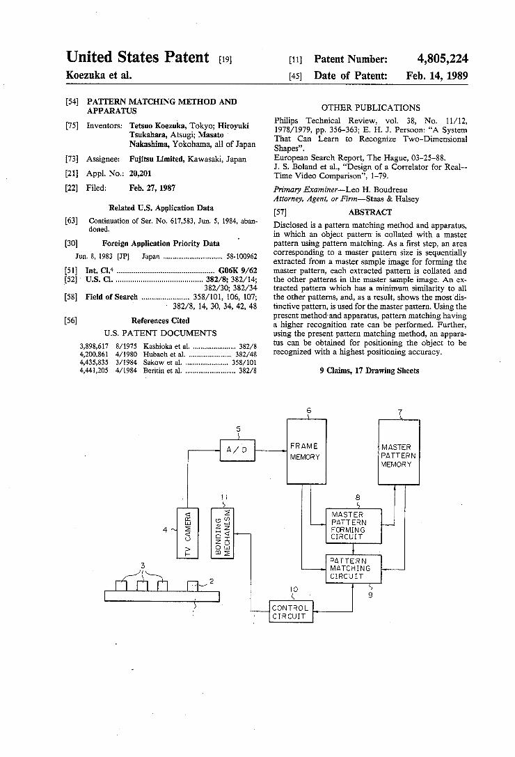
Philips Technical Review, vol. 38, No. 11/12, 1978/1979, pp. 356-363; E. H. J. Persoon: "A System That Can Learn to Recognize Two-Dimensional Shapes”. European Search Report, The Hague, 03-25-88. J. S. Boland et al., “Design of a Correlator for Real Time Video Comparison', 1-79. Primary Examiner-Leo H. Boudreau Attorney, Agent, or Firm-Staas & Halsey (57) ABSTRACT Disclosed is a pattern matching method and apparatus, in which an object pattern is collated with a master pattern using pattern matching. As a first step, an area corresponding to a master pattern size is sequentially extracted from a master sample image for forming the master pattern, each extracted pattern is collated and the other patterns in the master sample image. An ex tracted pattern which has a minimum similarity to all the other patterns, and, as a result, shows the most dis tinctive pattern, is used for the master pattern. Using the present method and apparatus, pattern matching having a higher recognition rate can be performed. Further, using the present pattern matching method, an appara tus can be obtained for positioning the object to be recognized with a highest positioning accuracy.
9 Claims, 17 Drawing Sheets
FRAME MEMORY
MASTER PATTERN MEMORY
MASTER PATTERN FORMING CIRCUIT
PATTERN MATCHING CIRCUIT
CONTROL CIRCUIT

U.S. Patent
FRAME MEMORY
Feb. 14, 1989 Sheet 2 of 17
Fig. 2
MASTER PATTERN MEMORY
EXTRACTION CIRCUIT
PATTERN MATCHING CONTROL CIRCUIT
SIMILAR PATTERN DETECTION CIRCUIT
PATTERN MATCHING CIRCUIT
4,805,224
4,805,224 Sheet 3 of 17 Feb. 14, 1989 U.S. Patent
U.S. Patent Feb. 14, 1989 Sheet 4 of 17 4,805,224
Fig. 4A 2 (3 M2(O,O)
(O,O) 5 tool sis z t ES 5. (OO) POSITION ( m, n)
Fig. 4B () 2 g H M2 (x1, y1)
Y 5 to <-
2 >SS 2 Ég ES w
I (x,y)(x2, y2) POSITION (m, n)
Fig. 4C 2 g
E2 too 4. 1 SSS M2(X3, y3)
7 2
2 is - CD 5. (X3,y3) POSITION ( m, n)
U.S. Patent Feb. 14, 1989 Sheet 5 of 17 4,805,224
Fig. 5 8
E. EXTRACTION SIZE COMMAND CIRCUIT
MASTER FRAME EXTRACTION MEMORY CIRCUIT PATTERN
MEMORY
PATTERN MATCHING CONTROL CIRCUIT
82
EXTRACTION
CIRCUIT
SLMLAR PATTERN DETECTION - 83 CIRCUIT
S(92)
PATTERN MATCHING CIRCUIT
4,805,224 Sheet 6 of 17 Feb. 14, 1989 U.S. Patent
N Q N NJ
N
NJ NJ R] R]
U.S. Patent Feb. 14, 1989 Sheet 7 of 17 4,805,224
Fig. 7
OO
M2 min
A LOWABLE VALUE d 6 %
OPTIMUM EXTRACTION SIZE --
EXT RACTION PICTURE SIZE SIZE
U.S. Patent Feb. 14, 1989 Sheet 8 of 17 4,805,224
Fig. 8 6 9 s 7 81 -,
FRAME EXTRACTION MASTER PATTERN MEMORY
CIRCUIT MEMORY
PATTERN MATCH ING CONTROL CIRCUIT
82
PEAK INTERVAL CHECKING CIRCUIT
87
2ND ORDER
DIFFERENTIAL-se CIRCUIT
SMAR PATTERN DETECTION CIRCUIT
83
PATTERN MATCHING CIRCUIT
4,805,224 Sheet 9 of 17 Feb. 14, 1989 U.S. Patent
NO I LISOCH
MATCHING PATTERN
DEGREE
POSITION

U.S. Patent Feb. 14, 1989 Sheet 10 of 17 4,805,224
Fig. IO
77
CD 2 5
76 Y PATTERN
a MATCHING - CD DEGREE CL Cl C)
POSITION
U.S. Patent Feb. 14, 1989 Sheet 11 of 17 4,805,224
Fig.11
CD 2 H
s PATTERN
5ul MATCHING DEGREE
s 5. POSITION
U.S. Patent Feb. 14, 1989 Sheet 12 of 17 4,805,224
Fig. 2A -/-
Fig. 12B
Aa
Fig. I2C
—ll
U.S. Patent Feb. 14, 1989 Sheet 13 of 17 4,805,224
Fig. 13A u/N
Fig. 13B
Ab
Fig. 13C
-4-
U.S. Patent
6 s
FRAME r ADDRESS COUNTER
815
X SIZE | | | REGISTER
MEMORY
Feb. 14, 1989 Sheet 14 of 17
Fig. 14 8
8
X EXTRACTIO REGISTER
813
84
X SIZE COUNTER
812
Y EXTRACTION REGISTER
814
Y ADDRESS COUNTER
Y SIZE REGISTER
PATTERN MATCHING CIRCUIT
9 82t
START CK
4,805,224
MASTER MEMORY
-- 842
Y SIZE - 84 COUNTER
U.S. Patent Feb. 14, 1989 Sheet 15 of 17 4,805,224
Fig. 15
Molx REGISTER
COMPARATOR COMPARATOR
834
S (92)
U.S. Patent Feb. 14, 1989 Sheet 16 of 17 4,805,224
Fig. 16 Fig. 16 A
PATTERN MEMORY
U.S. Patent Feb. 14, 1989 Sheet 17 of 17 4,805,224
Fig. 16B 9
93 94 CORRELATOR-1 CORRELATOR-2
93 h 932 || --------|| || --------1942
; Ele ---------- TRI
ET is - - e 4 3
952
9C)
A DDER
96 ND
DATA MEMORY
ATA REGISTER MEMORY
9 O
4,805,224 1.
PATTERN MATCHING METHOD AND APPARATUS
This is a continuation of co-pending application Ser. No. 617,583 filed on June 5, 1985 now abandoned.
BACKGROUND OF THE INVENTION
(1) Field of the Invention The present invention relates to a pattern recognition
apparatus, more particularly to a pattern matching method and apparatus wherein the optimum master pattern can be selected quantitatively when the pattern matching method is performed.
(2) Description of the Prior Art The inventors of the present application have already
disclosed a Master Pattern Pick Up Method in Japanese unexamined patent publication (Kokai) No. 59-4130. This publication discloses a method of forming a master pattern using a pattern matching. In this method, only the appropriateness of the master pattern indicated by an operator is checked, and the best method of forming a master pattern is not always provided. That is, the master pattern indicated by the operator is checked only for whether it has similar patterns or not in the image picture. The most appropriate master pattern or the master pattern having the most distinctive features, which has a minimum similarity to the other patterns in the image, is not selected. Also, since this must be deter
10
15
20
25
mined by the operator, there is little or no reduction of 30 the work load on the operator.
SUMMARY OF THE INVENTION
An object of the present invention is to provide a pattern matching method and apparatus based on a concept of picking up a master sample that includes a master pattern and automatically detecting a pattern having the most distinctive features, wherein operation by the operator is not necessary as the most appropriate master pattern is automatically obtained. That is, the master pattern in the image picture having the most distinctive features i.e., having the minimum matching degree to the other patterns, is selected and memorized, and pattern recognition having a high recognition rate and highly accurate positioning through the use of pat tern recognition is carried out using the master pattern. According to an aspect of the present invention, there
is provided a pattern matching method comprising the steps of, sequentially extracting a pattern with a prede termined size from an image in order to form a master pattern, mutually comparing each extracted pattern with all the other patterns in the image, registering the extracted pattern which has the minimum similarity to the other patterns, as a master pattern, and identifying the object pattern by a pattern matching procedure between the image including the object pattern and the master pattern. According to another aspect of the present invention,
there is provided a pattern matching apparatus having an image pickup system for picking up an image of a sample put on a sample feed mechanism; an analog to digital (A/D) converter circuit converts an analog pickup signal from the image pickup system to a digital signal. After conversion, an object pattern memory receives the output of the A/D converter circuit. Also included are a master pattern forming circuit, con nected to the object pattern memory; a master pattern memory, connected to the master pattern forming cir
35
45
50
55
60
65
2 cuit; and a pattern matching circuit connected to the object pattern memory and the master pattern memory; The master pattern forming circuit includes a distinc tive pattern detection circuit for detecting the most distinctive pattern portion in the object pattern memory and for storing the detected pattern portion into the master pattern memory.
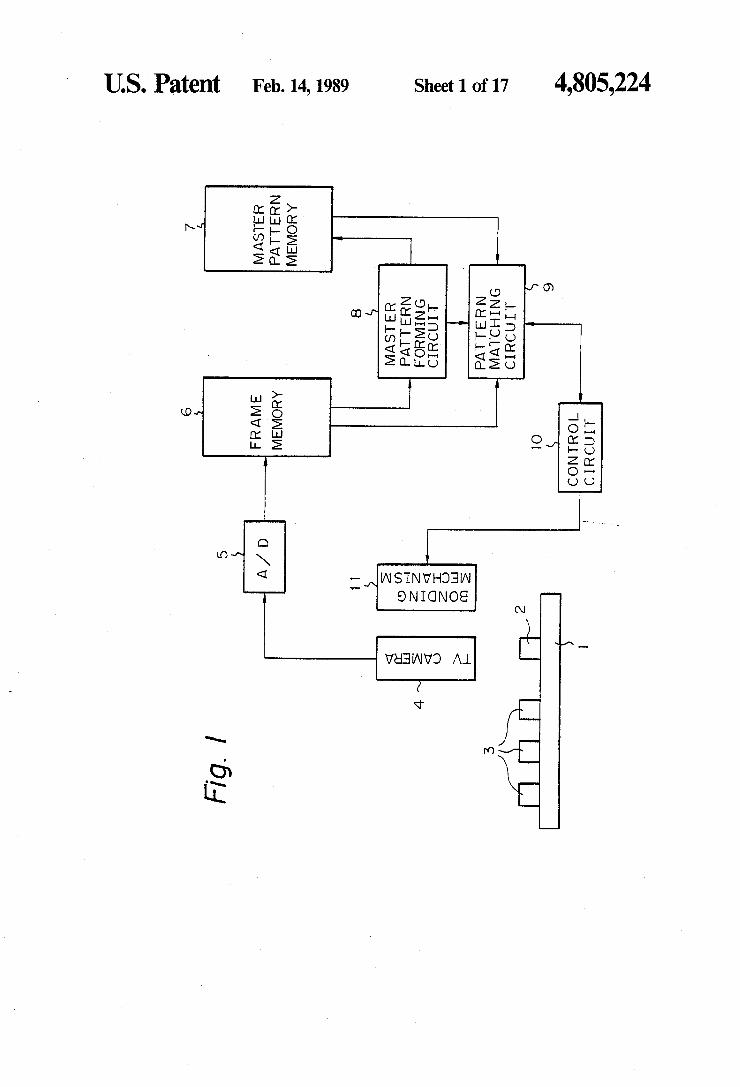
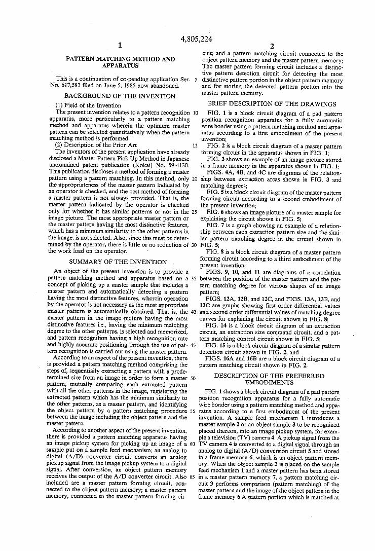
BRIEF DESCRIPTION OF THE DRAWINGS FIG. 1 is a block circuit diagram of a pad pattern
position recognition apparatus for a fully automatic wire bonder using a pattern matching method and appa ratus according to a first embodiment of the present invention; FIG. 2 is a block circuit diagram of a master pattern
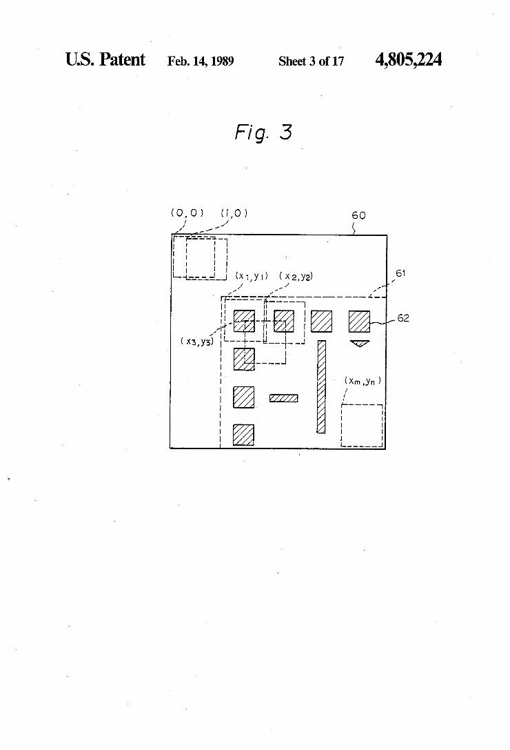
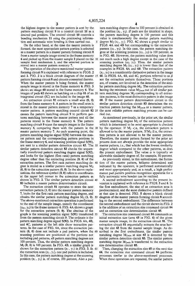
forming circuit in the apparatus shown in FIG. 1; FIG. 3 shows an example of an image picture stored
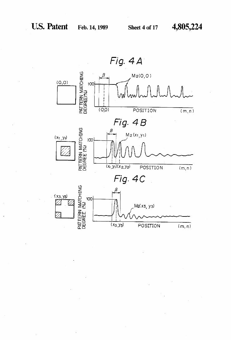
in a frame memory in the apparatus shown in FIG. 1; FIGS. 4A, 4B, and 4C are diagrams of the relation
ship between extraction areas shown in FIG. 3 and matching degrees;
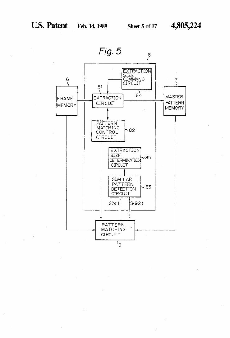
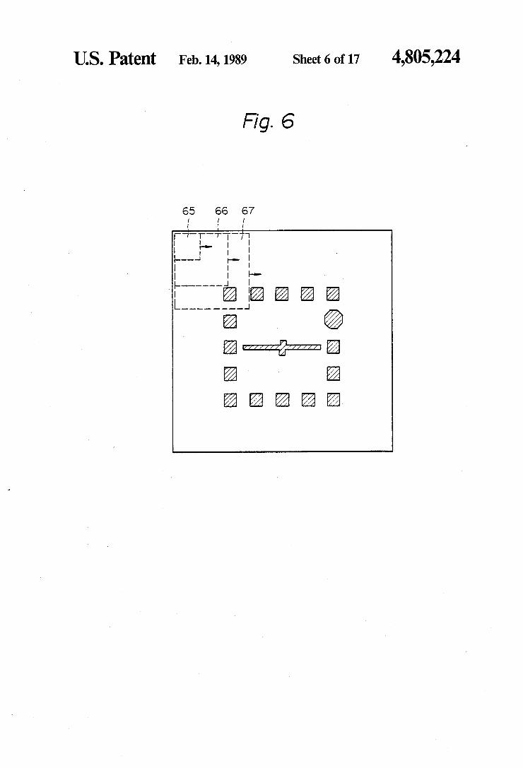
FIG. 5 is a block circuit diagram of the master pattern forming circuit according to a second embodiment of the present invention; FIG. 6 shows an image picture of a master sample for
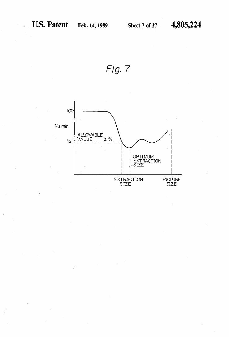
explaining the circuit shown in FIG. 5; FIG. 7 is a graph showing an example of a relation
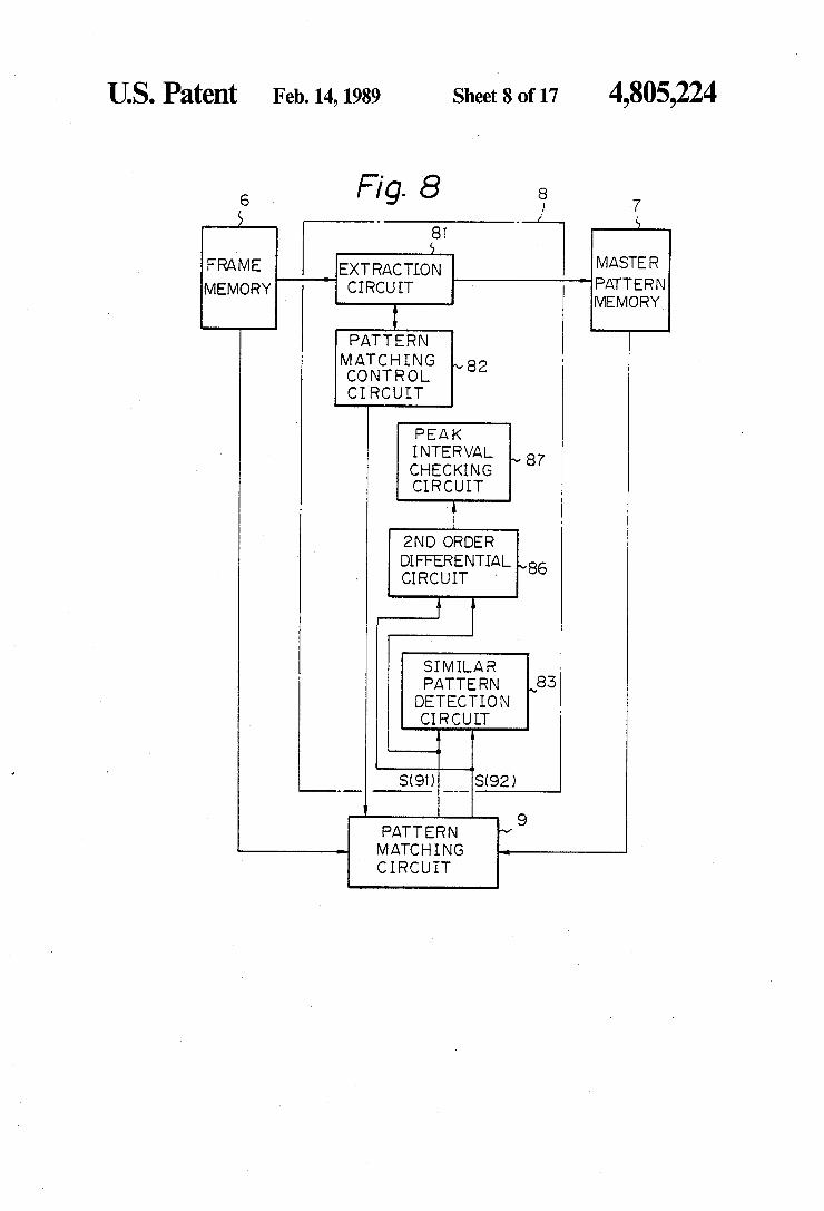
ship between each extraction pattern size and the simi lar pattern matching degree in the circuit shown in FIG. 5; FIG. 8 is a block circuit diagram of a master pattern
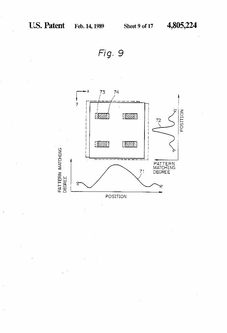
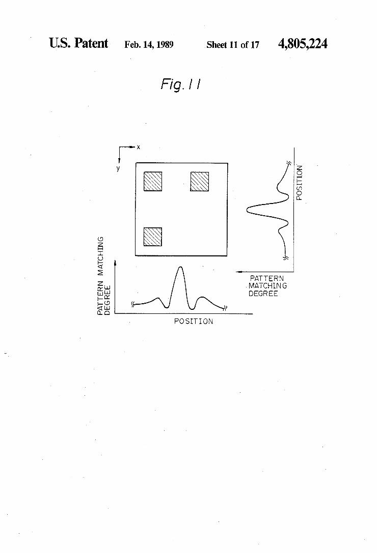
forming circuit according to a third embodiment of the present invention; FIGS. 9, 10, and 11 are diagrams of a correlation
between the position of the master pattern and the pat tern matching degree for various shapes of an image pattern;
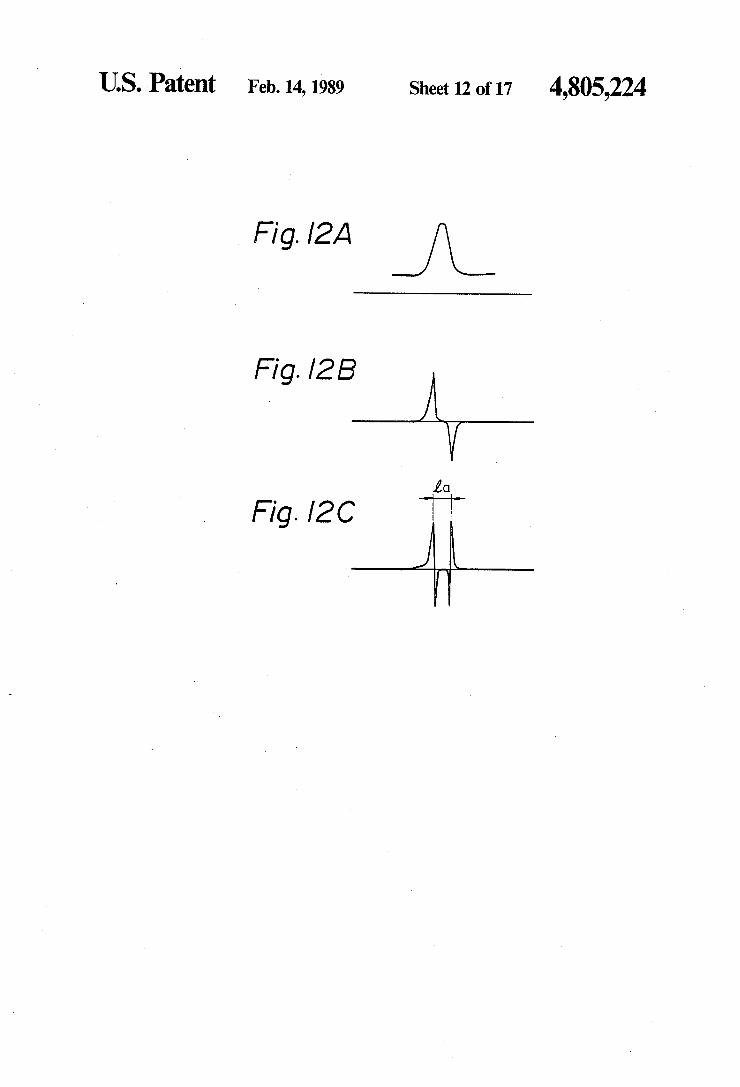
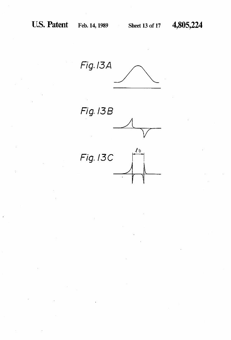
FIGS. 12A, 12B, and 12C, and FIGS. 13A, 13B, and 13C are graphs showing first order differential values and second order differential values of matching degree curves for explaining the circuit shown in FIG. 8; FIG. 14 is a block circuit diagram of an extraction
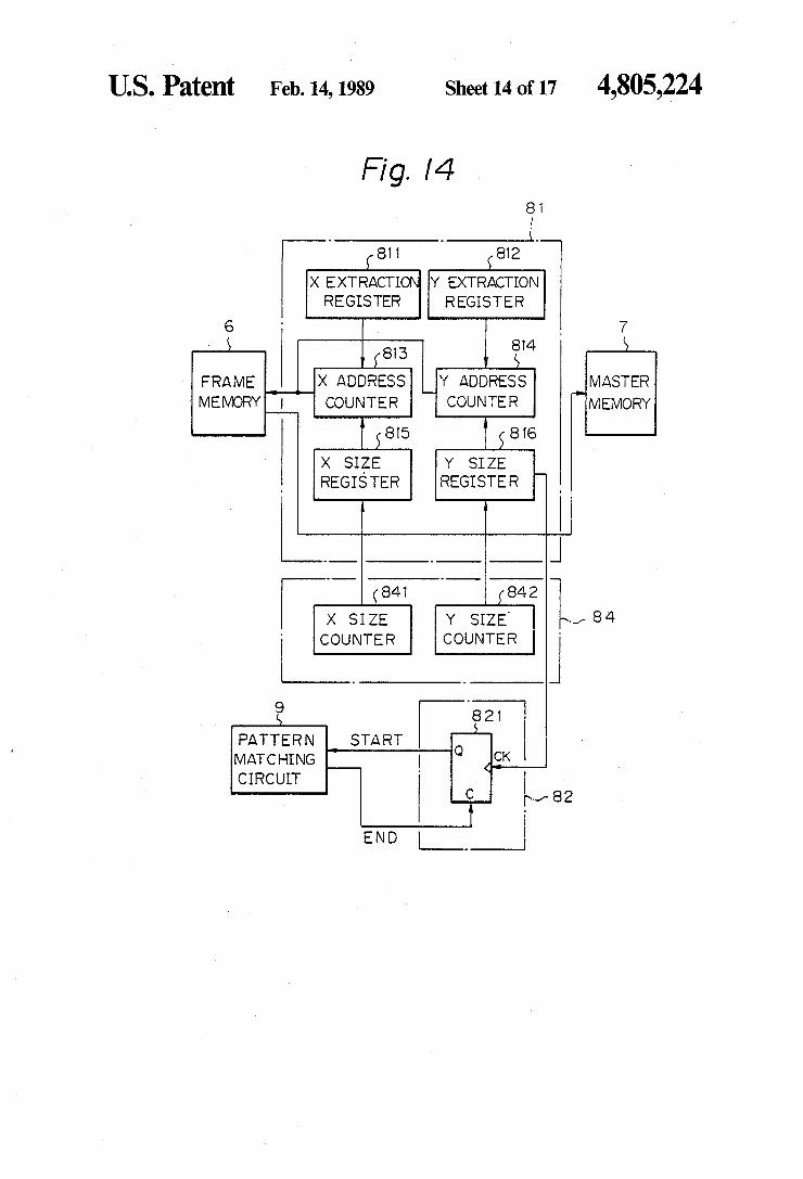
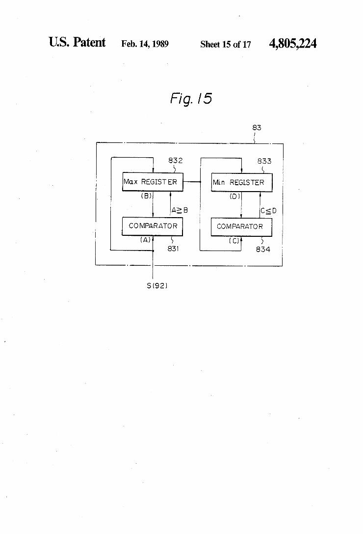
circuit, an extraction size command circuit, and a pat tern matching control circuit shown in FIG. 5; FIG. 15 is a block circuit diagram of a similar pattern
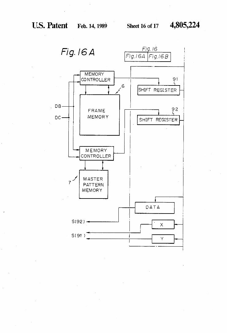
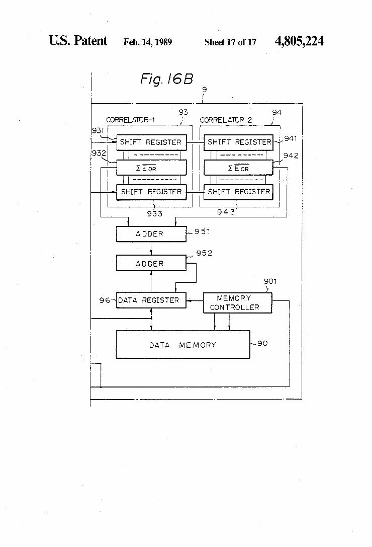
detection circuit shown in FIG. 2; and FIGS. 16A and 16B are a block circuit diagram of a
pattern matching circuit shown in FIG. 2. DESCRIPTION OF THE PREFERRED
EMBODIMENTS
FIG. 1 shows a block circuit diagram of a pad pattern position recognition apparatus for a fully automatic wire bonder using a pattern matching method and appa ratus according to a first embodiment of the present invention. A sample feed mechanism 1 introduces a master sample 2 or an object sample 3 to be recognized placed thereon, into an image pickup system, for exam ple a television (TV) camera 4. A pickup signal from the TV camera 4 is converted to a digital signal through an analog to digital (A/D) conversion circuit 5 and stored in a frame memory 6, which is an object pattern mem ory. When the object sample 3 is placed on the sample feed mechanism 1 and a master pattern has been stored in a master pattern memory 7, a pattern matching cir cuit 9 performs comparison (pattern matching) of the master pattern and the image of the object pattern in the frame memory 6 A pattern portion which is matched at
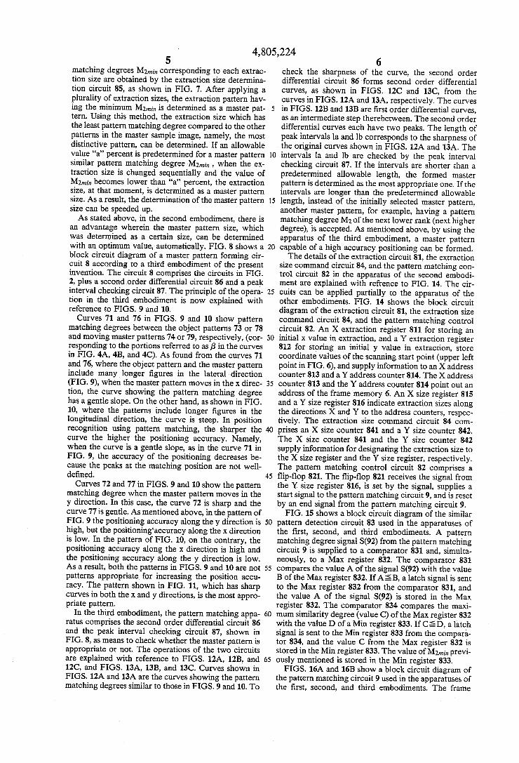
4,805,224 3
the highest degree to the master pattern is sent by the pattern matching circuit 9 to a control circuit 10 as a desired pad position. The control circuit 10 controls a bonding mechanism 11 using the positioning informa tion and automatic wire bonding is then carried out. On the other hand, at the time the master pattern is
formed, the most appropriate pattern portion is selected as a master pattern in a master pattern forming circuit 8 from a master sample image stored in the frame memory 6 and picked up from the master sample 2 placed on the sample feed mechanism 1, and the selected portion is stored into a master pattern memory 7. The operation of the above-mentioned master pattern
forming circuit 8 is explained with reference to FIGS. 2 and 3. FIG. 2 is a block circuit diagram of the master pattern forming circuit 8 and circuits connected thereto. When the master pattern is being formed, the master sample image is stored in the frame memory 6. FIG. 3 shows an image 60 stored in the frame memory 6. The images of pads 62 shown as hatching on a chip 61 of an integrated circuit (IC) are included in the image 60. An extraction circuit 81 extracts a small area (0, 0)
from the frame memory 6. A pattern in the small area is
15
stored in the master pattern memory 7 as a temporary master pattern. A pattern matching control circuit 82 causes the pattern matching circuit 9 to perform pat terns matching between the master pattern and all the patterns stored in the frame memory 6. The pattern matching circuit 9 scans the sample images in the frame memory 6, comparing them with the pattern in the master pattern memory 7. At each scanning point, the pattern matching degree signal S(92) between the mas ter pattern and the corresponding pattern portions in the frame memory 6, and scanning position signal S(91), are sent to a similar pattern detection circuit 83. The similar pattern detection circuit 83 checks the sequen tially transferred pattern matching degree signal S(92), and looks for the highest (first rank) pattern matching degree other than the extracting position (0, 0) of the extraction pattern. The first rank pattern matching de gree is stored as a similar pattern matching degree M2 (0, 0) to the extraction pattern (0, 0). In the above expla nations, the reference symbol (0, 0) refers to coordinates at the upper left corner in the extraction pattern as shown in FIG. 2. The similar pattern detection circuit 83 includes a master pattern determination circuit. The extraction circuit 81 operates to store the next
extraction pattern (1,0) into the master pattern memory 7, looks for the first rank pattern matching degree, and obtains the similar pattern matching degree M2 (1, 0). The above-mentioned extraction operation is performed to the end of the sample image, namely the coordinates (xn, yn) in the frame memory 6. FIG. 4A shows a graph for the extraction pattern (0, 0). The abscissa of the graph is the scanning position signal S(91) transferred from the pattern matching circuit 9. The ordinate is the pattern matching degree signal S(92). In FIGS. 4A, 4B, and 4C, patterns at the left side show extraction pat terns. In the case of FIG. 4A, since the extraction pat tern (0, 0) does not include a pad pattern, when the scanning positions are positioned at the portions not including pad patterns, all pattern matching degrees are 100 percent. Thus, the similar pattern matching degree M2 (0, 0) is 100 percent. In FIG. 4B, a similar graph is shown for the extraction pattern (x, y) in FIG. 3. In the extraction area (x, y1), one pad pattern is included. In this case, the pattern matching degree at the scanning position (x1, y1) is, of course, 100 percent, Also a pat
25
30
35
45
50
55
60
65
4. tern matching degree close to 100 percent is obtained at the position (x2, y2). If pads are the identical in shape, the pattern matching degree is 100 percent and this value is simultaneously the similar pattern matching degree M2 (x1, y1). FIG. 4C shows a graph similar to FIGS. 4A and 4B but corresponding to the extraction pattern (x3, y3). In this case, the pattern matching de gree at the scanning position (X3, y3) is 100 percent, as in FIG. 4B. However, the pattern matching value does not reach such a high degree except in the case of the scanning position (x3, y3). Thus, the similar pattern matching degree M2 (x3, y3) is lower than that of the examples in FIGS. 4A and 4B, The extraction pattern (x3, y3) is a considerably distinctive pattern in the image 60. In FIGS. 4A, 4B, and 4C, portions referred to as g are the extraction pattern themselves. These portions are, of course, not involved in the detection of the simi lar pattern matching degree M2. The extraction pattern having the minimum value M2nin out of all similar pat tern matching degrees M2 corresponding to all extrac tion patterns, is the most distinctive pattern in the image 60. If the master pattern determination circuit in the similar pattern detection circuit 83 determines the ex traction pattern having the M2nin as a master pattern, the most reliable pattern matching process can be car ried out. As mentioned previously, in the prior art, the similar
pattern matching degree M2 of the extraction pattern which is determined to be most appropriate is checked by the operator. If M2 < c, the extraction pattern is allowed to be the master pattern. If M22 a, the extrac tion pattern is not allowed to be the master pattern. Therefore, the master pattern formed by the prior art process does not always provide the most appropriate master pattern, i.e., that which has the lowest similarity degree which compared to the other patterns, as does the present embodiment. The value a is typically an allowable similarity degree of, for example, 80 percent. As previously stated, in this embodiment, the forma
tion of the master pattern, hitherto determined and indicated by the operator, is performed automatically and most appropriately and, as a result, a high perfor mance pad pattern position recognition apparatus for a fully automatic wire bonder can be realized. A second embodiment according to the present in
vention is explained with reference to FIGS. 5 and 6. In the first embodiment, the size of an extraction area is predetermined, and the most distinctive pattern defined at that size is detected. FIG. 5 shows a block circuit diagram of the master pattern forming circuit 8 accord ing to the second embodiment. The difference between the second embodiment and the circuit shown in FIG. 2 is the addition of an extraction size command circuit 84 and an extraction size determination circuit 85. The extraction size command circuit 84 commands an
initial extraction size (area 65 in FIG. 6) of the given master sample image, to the extraction circuit 81. The extraction circuit 81 sequentially extracts the area hav ing the size 65 from the master sample image. As de scribed in the first embodiment, the similar pattern matching degree M2nin at size 65 is detected by the similar pattern detection circuit 83. The similar pattern matching degree M2nin is transferred to the extraction size determination circuit 85. Then, changing the extraction size 65 to the next size
66, the extraction size command circuit 84 performs processes similar to the above-mentioned processes. When these operations are repeated, the similar pattern
4,805,224 5
matching degrees M2min corresponding to each extrac tion size are obtained by the extraction size determina tion circuit 85, as shown in FIG. 7. After applying a plurality of extraction sizes, the extraction pattern hav ing the minimum M2nin is determined as a master pat tern. Using this method, the extraction size which has the least pattern matching degree compared to the other patterns in the master sample image, namely, the most distinctive pattern, can be determined. If an allowable value "a' percent is predetermined for a master pattern similar pattern matching degree M2nin, when the ex traction size is changed sequentially and the value of M2in becomes lower than 'a' percent, the extraction size, at that moment, is determined as a master pattern size. As a result, the determination of the master pattern size can be speeded up. As stated above, in the second embodiment, there is
an advantage wherein the master pattern size, which was determined as a certain size, can be determined with an optimum value, automatically. FIG. 8 shows a block circuit diagram of a master pattern forming cir cuit 8 according to a third embodiment of the present invention. The circuit 8 comprises the circuits in FIG. 2, plus a second order differential circuit 86 and a peak interval checking circuit 87. The principle of the opera tion in the third embodiment is now explained with reference to FIGS. 9 and 10. Curves 71 and 76 in FIGS. 9 and 10 show pattern
matching degrees between the object patterns 73 or 78 and moving master patterns 74 or 79, respectively, (cor responding to the portions referred to as 6 in the curves in FIG. 4A, 4B, and 4C). As found from the curves 71 and 76, where the object pattern and the master pattern include many longer figures in the lateral direction (FIG. 9), when the master pattern moves in the x direc tion, the curve showing the pattern matching degree has a gentle slope. On the other hand, as shown in FIG. 10, where the patterns include longer figures in the longitudinal direction, the curve is steep. In position recognition using pattern matching, the sharper the curve the higher the positioning accuracy. Namely, when the curve is a gentle slope, as in the curve 71 in FIG. 9, the accuracy of the positioning decreases be cause the peaks at the matching position are not well defined. Curves 72 and 77 in FIGS. 9 and 10 show the pattern
matching degree when the master pattern moves in the y direction. In this case, the curve 72 is sharp and the curve 77 is gentle. As mentioned above, in the pattern of FIG. 9 the positioning accuracy along they direction is high, but the positioning'accuracy along the X direction is low. In the pattern of FIG. 10, on the contrary, the positioning accuracy along the X direction is high and the positioning accuracy along they direction is low. As a result, both the patterns in FIGS. 9 and 10 are not patterns appropriate for increasing the position accu racy. The pattern shown in FIG. 11, which has sharp curves in both the x and y directions, is the most appro priate pattern.
In the third embodiment, the pattern matching appa ratus comprises the second order differential circuit 86 and the peak interval checking circuit 87, shown in FIG. 8, as means to check whether the master pattern is appropriate or not. The operations of the two circuits are explained with reference to FIGS. 12A, 12B, and 12C, and FIGS. 13A, 13B, and 13C. Curves shown in FIGS. 12A and 13A are the curves showing the pattern matching degrees similar to those in FIGS. 9 and 10. To
10
15
20
25
30
35
40
45
50
55
60
65
6 check the sharpness of the curve, the second order differential circuit 86 forms second order differential curves, as shown in FIGS. 12C and 13C, from the curves in FIGS. 12A and 13A, respectively. The curves in FIGS. 12B and 13B are first order differential curves, as an intermediate step therebetween. The second order differential curves each have two peaks. The length of peak intervals la and lb corresponds to the sharpness of the original curves shown in FIGS. 12A and 13A. The intervals la and lb are checked by the peak interval checking circuit 87. If the intervals are shorter than a predetermined allowable length, the formed master pattern is determined as the most appropriate one. If the intervals are longer than the predetermined allowable length, instead of the initially selected master pattern, another master pattern, for example, having a pattern matching degree M2 of the next lower rank (next higher degree), is accepted. As mentioned above, by using the apparatus of the third embodiment, a master pattern capable of a high accuracy positioning can be formed. The details of the extraction circuit 81, the extraction
size command circuit 84, and the pattern matching con trol circuit 82 in the apparatus of the second embodi ment are explained with refrence to FIG. 14. The cir cuits can be applied partially to the apparatus of the other embodiments. FIG. 14 shows the block circuit diagram of the extraction circuit 81, the extraction size command circuit 84, and the pattern matching control circuit 82. An X extraction register 811 for storing an initial x value in extraction, and a Y extraction register 812 for storing an initial y value in extraction, store coordinate values of the scanning start point (upper left point in FIG. 6), and supply information to an X address counter 813 and a Yaddress counter 814. The X address counter 813 and the Yaddress counter 814 point out an address of the frame memory 6. An X size register 815 and a Y size register 816 indicate extraction sizes along the directions X and Y to the address counters, respec tively. The extraction size command circuit 84 com prises an X size counter 841 and a Y size counter 842. The X size counter 841 and the Y size counter 842 supply information for designating the extraction size to the X size register and the Y size register, respectively. The pattern matching control circuit 82 comprises a flip-flop 821. The flip-flop 821 receives the signal from the Y size register 816, is set by the signal, supplies a start signal to the pattern matching circuit 9, and is reset by an end signal from the pattern matching circuit 9. FIG. 15 shows a block circuit diagram of the similar
pattern detection circuit 83 used in the apparatuses of the first, second, and third embodiments. A pattern matching degree signal S(92) from the pattern matching circuit 9 is supplied to a comparator 831 and, simulta neously, to a Max register 832. The comparator 831 compares the value A of the signal S(92) with the value B of the Max register 832. If ASB, a latch signal is sent to the Max register 832 from the comparator 831, and the value A of the signal S(92) is stored in the Max register 832. The comparator 834 compares the maxi mum similarity degree (value C) of the Max register 832 with the value D of a Min register 833. If CSD, a latch signal is sent to the Min register 833 from the compara tor 834, and the value C from the Max register 832 is stored in the Min register 833. The value of M2nin previ ously mentioned is stored in the Min register 833. FIGS. 16A and 16B show a block circuit diagram of
the pattern matching circuit 9 used in the apparatuses of the first, second, and third embodiments. The frame
4,805,224 7
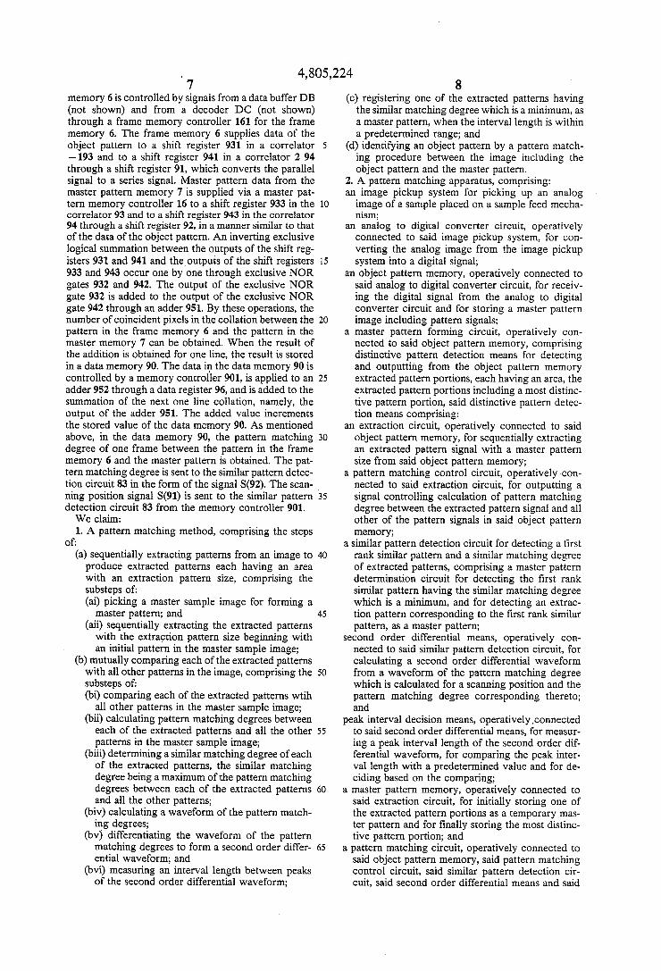
memory 6 is controlled by signals from a data buffer DB (not shown) and from a decoder DC (not shown) through a frame memory controller 161 for the frame memory 6. The frame memory 6 supplies data of the object pattern to a shift register 931 in a correlator -193 and to a shift register 941 in a correlator 294 through a shift register 91, which converts the parallel signal to a series signal. Master pattern data from the master pattern memory 7 is supplied via a master pat tern memory controller 16 to a shift register 933 in the correlator 93 and to a shift register 943 in the correlator 94 through a shift register 92, in a manner similar to that of the data of the object pattern. An inverting exclusive logical summation between the outputs of the shift reg isters 931 and 941 and the outputs of the shift registers 933 and 943 occur one by one through exclusive NOR gates 932 and 942. The output of the exclusive NOR gate 932 is added to the output of the exclusive NOR gate 942 through an adder 951. By these operations, the number of coincident pixels in the collation between the pattern in the frame memory 6 and the pattern in the master memory 7 can be obtained. When the result of the addition is obtained for one line, the result is stored in a data memory 90. The data in the data memory 90 is controlled by a memory controller 901, is applied to an adder 952 through a data register 96, and is added to the Summation of the next one line collation, namely, the output of the adder 951. The added value increments the stored value of the data memory 90. As mentioned above, in the data memory 90, the pattern matching degree of one frame between the pattern in the frame memory 6 and the master pattern is obtained. The pat tern matching degree is sent to the similar pattern detec tion circuit 83 in the form of the signal S(92). The scan ning position signal S(91) is sent to the similar pattern detection circuit 83 from the memory controller 901. We claim: 1. A pattern matching method, comprising the steps
of: (a) sequentially extracting patterns from an image to produce extracted patterns each having an area with an extraction pattern size, comprising the substeps of: (ai) picking a master sample image for forming a
master pattern; and (aii) sequentially extracting the extracted patterns
with the extraction pattern size beginning with an initial pattern in the master sample image;
(b) mutually comparing each of the extracted patterns with all other patterns in the image, comprising the substeps of: (bi) comparing each of the extracted patterns wtih
all other patterns in the master sample image; (bii) calculating pattern matching degrees between
each of the extracted patterns and all the other patterns in the master sample image;
(biii) determining a similar matching degree of each of the extracted patterns, the similar matching degree being a maximum of the pattern matching degrees between each of the extracted patterns and all the other patterns;
(biv) calculating a waveform of the pattern match ing degrees;
(bv) differentiating the waveform of the pattern matching degrees to form a second order differ ential waveform; and
(bvi) measuring an interval length between peaks of the second order differential waveform;
5
10
5
20
25
30
35
40
45
50
55
60
65
8 (c) registering one of the extracted patterns having
the similar matching degree which is a minimum, as a master pattern, when the interval length is within a predetermined range; and
(d) identifying an object pattern by a pattern match ing procedure between the image including the object pattern and the master pattern.
2. A pattern matching apparatus, comprising: an image pickup system for picking up an analog image of a sample placed on a sample feed mecha nSn;
an analog to digital converter circuit, operatively connected to said image pickup system, for con verting the analog image from the image pickup System into a digital signal;
an object pattern memory, operatively connected to said analog to digital converter circuit, for receiv ing the digital signal from the analog to digital converter circuit and for storing a master pattern image including pattern signals;
a master pattern forming circuit, operatively con nected to said object pattern memory, comprising distinctive pattern detection means for detecting and outputting from the object pattern memory extracted pattern portions, each having an area, the extracted pattern portions including a most distinc tive pattern portion, said distinctive pattern detec tion means comprising:
an extraction circuit, operatively connected to said object pattern memory, for sequentially extracting an extracted pattern signal with a master pattern size from said object pattern memory;
a pattern matching control circuit, operatively con nected to said extraction circuit, for outputting a signal controlling calculation of pattern matching degree between the extracted pattern signal and all other of the pattern signals in said object pattern memory;
a similar pattern detection circuit for detecting a first rank similar pattern and a similar matching degree of extracted patterns, comprising a master pattern determination circuit for detecting the first rank similar pattern having the similar matching degree which is a minimum, and for detecting an extrac tion pattern corresponding to the first rank similar pattern, as a master pattern;
second order differential means, operatively con nected to said similar pattern detection circuit, for calculating a second order differential waveform from a waveform of the pattern matching degree which is calculated for a scanning position and the pattern matching degree corresponding thereto; and
peak interval decision means, operatively.connected to said second order differential means, for measur ing a peak interval length of the second order dif ferential waveform, for comparing the peak inter vallength with a predetermined value and for de ciding based on the comparing;
a master pattern memory, operatively connected to said extraction circuit, for initially storing one of the extracted pattern portions as a temporary mas ter pattern and for finally storing the most distinc tive pattern portion; and
a pattern matching circuit, operatively connected to said object pattern memory, said pattern matching control circuit, said similar pattern detection cir cuit, said second order differential means and said
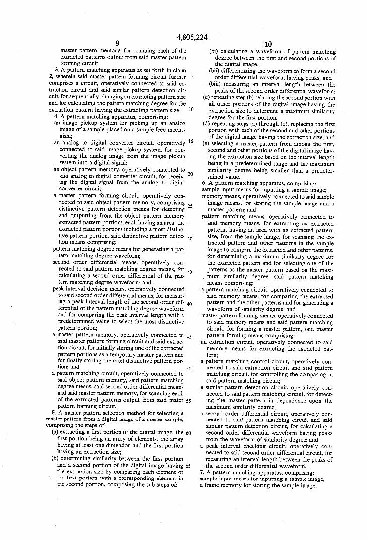
4,805,224 master pattern memory, for scanning each of the extracted patterns output from said master pattern forming circuit.
3. A pattern matching apparatus as set forth in claim 2, wherein said master pattern forming circuit further 5 comprises a circuit, operatively connected to said ex traction circuit and said similar pattern detection cir cuit, for sequentially changing an extracting pattern size and for calculating the pattern matching degree for the extraction pattern having the extracting pattern size.
4. A pattern matching apparatus, comprising: an image pickup system for picking up an analog image of a sample placed on a sample feed mecha nism;
an analog to digital converter circuit, operatively connected to said image pickup system, for con verting the analog image from the image pickup system into a digital signal;
an object pattern memory, operatively connected to said analog to digital converter circuit, for receiv ing the digital signal from the analog to digital converter circuit;
a master pattern forming circuit, operatively con nected to said object pattern memory, comprising distinctive pattern detection means for detecting and outputting from the object pattern memory
10
15
20
25
extracted pattern portions, each having an area, the extracted pattern portions including a most distinc tive pattern portion, said distinctive pattern detec tion means comprising:
pattern matching degree means for generating a pat tern matching degree waveform;
second order differential means, operatively con nected to said pattern matching degree means, for calculating a second order differential of the pat tern matching degree waveform; and
peak interval decision means, operatively connected to said second order differential means, for measur ing a peak interval length of the second order dif ferential of the pattern matching degree waveform and for comparing the peak interval length with a predetermined value to select the most distinctive pattern portion;
a master pattern memory, operatively connected to said master pattern forming circuit and said extrac tion circuit, for initially storing one of the extracted pattern portions as a temporary master pattern and for finally storing the most distinctive pattern por tion; and
a pattern matching circuit, operatively connected to said object pattern memory, said pattern matching degree means, said second order differential means and said master pattern memory, for scanning each of the extracted patterns output from said mater pattern forming circuit.
5. A master pattern selection method for selecting a master pattern from a digital image of a master sample, comprising the steps of:
(a) extracting a first portion of the digital image, the first portion being an array of elements, the array having at least one dimension and the first portion having an extraction size;
(b) determining similarity between the first portion and a second portion of the digital image having the extraction size by comparing each element of the first portion with a corresponding element in the second portion, comprising the sub steps of:
30
35
40
45
50
55
60
65
10 (bi) calculating a waveform of pattern matching
degree between the first and second portions of the digital image;
(bii) differentiating the waveform to form a second order differential waveform having peaks; and
(biii) measuring an interval length between the peaks of the second order differential waveform;
(c) repeating step (b) relacing the second portion with all other portions of the digital image having the extraction size to determine a maximum similarity degree for the first portion;
(d) repeating steps (a) through (c), replacing the first portion with each of the second and other portions of the digital image having the extraction size; and
(e) selecting a master pattern from among the first, second and other portions of the digital image hav ing the extraction size based on the interval length being in a predetermined range and the maximum similarity degree being smaller than a predeter mined value.
6. A pattern matching apparatus, comprising: sample input means for inputting a sample image; memory means, operatively connected to said sample image means, for storing the sample image and a master pattern; and
pattern matching means, operatively connected to said memory means, for extracting an extracted pattern, having an area with an extracted pattern size, from the sample image, for scanning the ex tracted pattern and other patterns in the sample image to compare the extracted and other patterns, for determining a maximum similarity degree for the extracted pattern and for selecting one of the patterns as the master pattern based on the maxi mum similarity degree, said pattern matching means comprising:
a pattern matching circuit, operatively connected to said memory means, for comparing the extracted pattern and the other patterns and for generating a waveform of similarity degree; and
master pattern forming means, operatively connected to said memory means and said pattern matching circuit, for forming a master pattern, said master pattern forming means comprising:
an extraction circuit, operatively connected to said memory means, for extracting the extracted pat tern;
a pattern matching control circuit, operatively con nected to said extraction circuit and said pattern matching circuit, for controlling the comparing in said pattern matching circuit;
a similar pattern detection circuit, operatively con nected to said pattern matching circuit, for detect ing the master pattern in dependence upon the maximum similarity degree;
a second order differential circuit, operatively con nected to said pattern matching circuit and said similar pattern detection circuit, for calculating a second order differential waveform having peaks from the waveform of similarity degree; and
a peak interval checking circuit, operatively con nected to said second order differential circuit, for measuring an interval length between the peaks of the second order differential waveform.
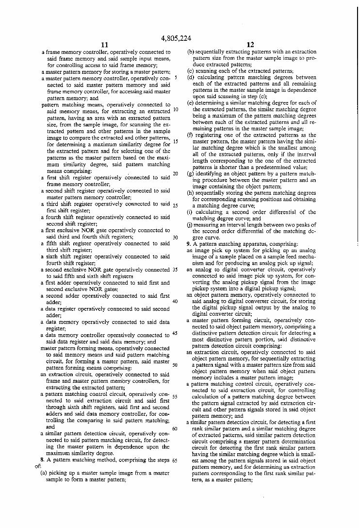
7. A pattern matching apparatus, comprising: sample input means for inputting a sample image; a frame memory for storing the sample image;
4,805,224 11
a frame memory controller, operatively connected to said frame memory and said sample input means, for controlling access to said frame memory;
a master pattern memory for storing a master pattern; a master pattern memory controller, operatively con
nected to said master pattern memory and said frame memory controller, for accessing said master pattern memory; and
pattern matching means, operatively connected to said memory means, for extracting an extracted pattern, having an area with an extracted pattern size, from the sample image, for Scanning the ex tracted pattern and other patterns in the sample image to compare the extracted and other patterns, for determining a maximum similarity degree for the extracted pattern and for selecting one of the patterns as the master pattern based on the maxi mum similarity degree, said pattern matching means comprising:
a first shift register operatively connected to said frame memory controller;
a second shift register operatively connected to said master pattern memory controller;
a third shift register operatively connected to said first shift register;
a fourth shift register operatively connected to said second shift register;
a first exclusive NOR gate operatively connected to said third and fourth shift registers;
a fifth shift register operatively connected to said third shift register;
a sixth shift register operatively connected to said fourth shift register;
a second exclusive NOR gate operatively connected to said fifth and sixth shift registers
a first adder operatively connected to said first and second exclusive NOR gates;
a second adder operatively connected to said first adder;
a data register operatively connected to said second adder;
a data memory operatively connected to said data register;
a data memory controller operatively connected to said data register and said data memory; and
master pattern forming means, operatively connected to said memory means and said pattern matching circuit, for forming a master pattern, said master pattern forming means comprising:
an extraction circuit, operatively connected to said frame and master pattern memory controllers, for extracting the extracted pattern;
a pattern matching control circuit, operatively con nected to said extraction circuit and said first through sixth shift registers, said first and second adders and said data memory controller, for con trolling the comparing in said pattern matching; and
a similar pattern detection circuit, operatively con nected to said pattern matching circuit, for detect ing the master pattern in dependence upon the maximum similarity degree.
8. A pattern matching method, comprising the steps of:
(a) picking up a master sample image from a master sample to form a master pattern;
5
10
15
20
25
30
35
45
50
55
60
65
12 (b) sequentially extracting patterns with an extraction
pattern size from the master sample image to pro duce extracted patterns;
(c) scanning each of the extracted patterns; (d) calculating pattern matching degrees between each of the extracted patterns and all remaining patterns in the master sample image in dependence upon said scanning in step (c);
(e) determining a similar matching degree for each of the extracted patterns, the similar matching degree being a maximum of the pattern matching degrees between each of the extracted patterns and all re maining patterns in the master sample image;
(f) registering one of the extracted patterns as the master pattern, the master pattern having the simi lar matching degree which is the smallest among all of the extracted patterns, only if the interval length corresponding to the one of the extracted patterns is shorter than a predetermined value;
(g) identifying an object pattern by a pattern match ing procedure between the master pattern and an image containing the object pattern;
(h) sequentially storing the pattern matching degrees for corresponding scanning positions and obtaining a matching degree curve;
(i) calculating a second order differential of the matching degree curve; and
(j) measuring an interval length between two peaks of the second order differential of the matching de gree curve.
9. A pattern matching apparatus, comprising: an image pick up system for picking up an analog image of a sample placed on a sample feed mecha nism and for producing an analog pick up signal;
an analog to digital converter circuit, operatively connected to said image pick up system, for con verting the analog pickup signal from the image pickup system into a digital pickup signal;
an object pattern memory, operatively connected to said analog to digital converter circuit, for storing the digital pickup signal output by the analog to digital converter circuit;
a master pattern forming circuit, operatively con nected to said object pattern memory, comprising a distinctive pattern detection circuit for detecting a most distinctive pattern portion, said distinctive pattern detection circuit comprising:
an extraction circuit, operatively connected to said object pattern memory, for sequentially extracting a pattern signal with a master pattern size from said object pattern memory when said object pattern memory includes a master pattern image;
a pattern matching control circuit, operatively con nected to said extraction circuit, for controlling calculation of a pattern matching degree between the pattern signal extracted by said extraction cir cuit and other pattern signals stored in said object pattern memory; and
a similar pattern detection circuit, for detecting a first rank similar pattern and a similar matching degree of extracted patterns, said similar pattern detection circuit comprising a master pattern determination circuit for detecting the first rank similar pattern having the similar matching degree which is small est among the pattern signals stored in said object pattern memory, and for determining an extraction pattern corresponding to the first rank similar pat tern, as a master pattern;
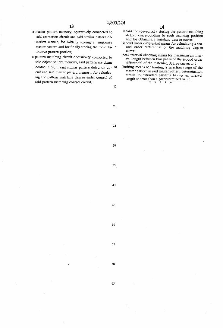
4,805,224 13
a master pattern memory, operatively connected to said extraction circuit and said similar pattern de tection circuit, for initially storing a temporary master pattern and for finally storing the most dis tinctive pattern portion;
a pattern matching circuit operatively connected to said object pattern memory, said pattern matching control circuit, said similar pattern detection cir cuit and said master pattern memory, for calculat ing the pattern matching degree under control of said pattern matching control circuit;
5
10
15
20
25
30
35
45
50
55
60
65
14 means for sequentially storing the pattern matching degree corresponding to each scanning position and for obtaining a matching degree curve;
second order differential means for calculating a sec ond order differential of the matching degree curve;
peak interval checking means for measuring an inter vallength between two peaks of the second order differential of the matching degree curve; and
limiting means for limiting a selection range of the master pattern in said master pattern determination circuit to extracted patterns having an interval length shorter than a predetermined value.
k k :k *k
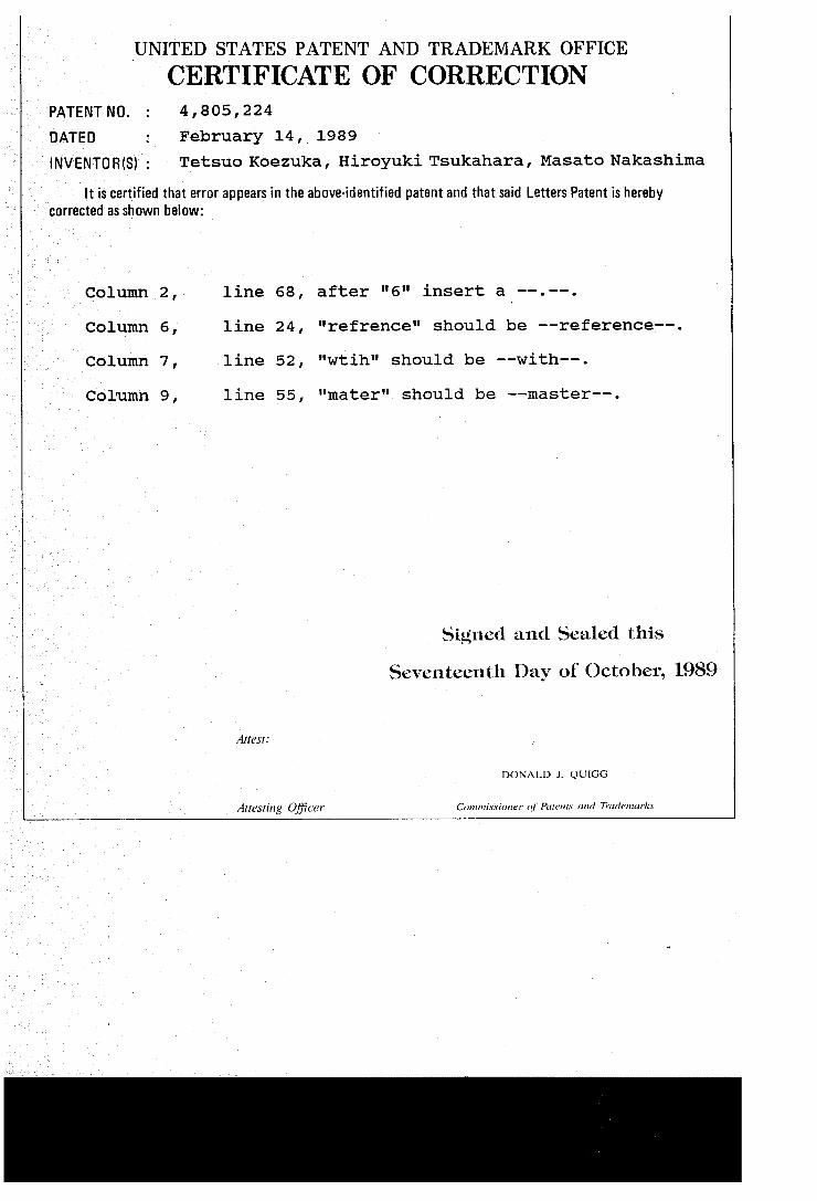
UNITED STATES PATENT AND TRADEMARK OFFICE
CERTIFICATE OF CORRECTION PATENT NO. : 4, 805, 224 DATED February 14, 1989 INVENTOR(S) : Tetsuo Koezuka, Hiroyuki Tsukahara, Masato Nakashima
It is certified that error appears in the above-identified patent and that said Letters Patent is hereby corrected as shown below:
Column 2, line 68, after "6" insert a -----.
Column 6, line 24, "refrence" should be --reference--.
Column 7, line 52, "wtih" should be --with--.
column 9, line 55, "mater" should be --master--.
Signed and Sealed this
Seventeenth Day of October, 1989
DONALD J. QUIGG
Attesting Officer Contnissioner of Pottents and Truciencirks