uniform plumbing code 2000
DESCRIPTION
Uniform plumbing code /sanitary design/ waterline design/ specifications of pipes/TRANSCRIPT

INFORMATION ABOUT THE COVER
IAPMO and its industry partners have long promoted the benefits of industry developed codesand standards. With this issue, IAPMO and the Western Fire Chiefs Association (WFCA)introduces a new design for the Uniform Codes. The design ensures that Uniform Codes willhave a distinctive and meaningful appearance. The new design contains various features thatwe hope will add to the value of these tried and tested codes.
The “rainbow” is called the Uniform Code Spectrum and represents that the Uniform Codefamily will cover the entire spectrum of construction codes, all maintained under a cohesiveumbrella and all providing for cross-representation and correlation between industryprofessionals and interested participants. The Uniform Code Spectrum extends onto the spineof the book and distinctively allows these books to be immediately located among hundreds ofother titles.
Each individual code has a distinctive color which will allow users through the years to findtheir own book among a shelf full of Uniform Codes. For example, the plumbing code is blue,the mechanical code is green and the fire code is red. This color is reflected both as thepredominant background of the book and is also contained as one of the color bands in thespectrum.
The Uniform Code cover also contains an embedded graphic which evokes scenes from thecode professional’s experience. This graphic is itself subdivided, with one portion beingidentical among all the Uniform Codes and another portion being unique to the particular code.Please join us in celebrating the new millennium by supporting the continued development andmaintenance of the Uniform Codes.
FAMILY OF CONSENSUS CODESAt IAPMO’s 70th Annual Education and Business Conference, held in Washington, DC, theInternational Association of Plumbing and Mechanical Officials and the National FireProtection Association executed an historic agreement. This agreement will provide for anintegrated family of consensus codes to be published and maintained by IAPMO and NFPA foruse in all sectors of the construction industry including, but not limited to plumbing,mechanical, fire, electrical and life safety. These codes will be developed and maintained toprotect our world community from harmful diseases passed by unsanitary conditions.
This agreement signifies a commitment by IAPMO and NFPA to ensure the safe installation ofsystems to protect our nations citizens. In national and international arenas, both IAPMO andNFPA will work side-by-side to promote the most inclusive and globally respected codes for allmankind. This family of integrated consensus codes will be available with the printing of the2003 editions.


UNIFORMPLUMBINGCODE™
2000 EDITION
Adopted at the Seventieth Annual Conference
September, 1999
INTERNATIONAL ASSOCIATION OF PLUMBING AND
MECHANICAL OFFICIALS
A Nonprofit Association
Copyright © 1999by
INTERNATIONAL ASSOCIATION OF PLUMBING AND MECHANICAL OFFICIALS
All Rights Reserved
No part of this work may be reproduced or recorded in any form or by any means, except as may be expresslypermitted in writing by the publisher.
Twenty-Second Edition
First Printing, October 1999
ISSN 0733-2335
Published by the International Association of Plumbing and Mechanical Officials
20001 Walnut Drive South, Walnut, CA, 91789-2825
REVISION MARKINGS
Code changes from the 1997 edition are marked in the margins as follows.
An arrow denotes a deletion
A vertical line denotes a change
Reprinted with permission from NFPA 54, National Fuel Gas Code, Copyright©1996, National Fire Protection Association, Quincy, MA 02269. This reprintedmaterial is not the complete and official position of the National Fire ProtectionAssociation, on the referenced subject which is represented only by the standard inits entirety.
NFPANFPA
The advantages of a uniform plumbing code adoptedby various local jurisdictions have long beenrecognized. Disorder in the industry as a result ofwidely divergent plumbing practices and the use ofmany different, often conflicting, plumbing codes bylocal jurisdictions influenced the Western PlumbingOfficials Association (now the InternationalAssociation of Plumbing and Mechanical Officials[IAPMO]) to form a committee of plumbinginspectors, master and journeyman plumbers,sanitary and mechanical engineers, assisted bypublic utility companies, and the plumbing industry tocreate a basic plumbing document for general use.The product of this effort, the first edition of theUniform Plumbing Code™ (UPC™) was officiallyadopted by IAPMO in 1945. The widespread use ofthis code over the past five decades by jurisdictionsthroughout the United States is testimony to its merit.
With the publication of the 1997 edition of theUPC, for the first time in history, a plumbing codehas been created which is the result of acollaboration of industry-wide entities. The NationalAssociation of Plumbing-Heating-CoolingContractors (NAPHCC) and the MechanicalContractors Association of America (MCAA) joinedforces with IAPMO to create this amalgamation ofthe most desirable aspects of the three mostrespected plumbing codes in existence. The 1994Uniform Plumbing Code published by IAPMO, the1993 ANSI A40 Safety Requirements for Plumbing™published by the MCAA and NAPHCC Joint TaskForce, and the National Standard Plumbing Code™published by NAPHCC were scrupulously dissectedand reassembled into this, the finest plumbing codedocument ever published.
With the publication of this 2000 edition of theUPC another signif icant milestone has beenreached. The American Society of SanitaryEngineers (ASSE), United Association ofJourneyman and Apprentices of the Plumbing andPipe Fitting Industry of the United States (UA), andthe Western Fire Chiefs Association (WFCA) haveendorsed the use of the UPC as the nationalplumbing for use in this county and internationally.
IAPMO and the National Fire ProtectionAssociation (NFPA) announced at the September,1999 IAPMO Conference they will work jointly todevelop IAPMO codes and standards using the
NFPA/ANSI consensus model. The 2003 edition ofthe IAPMO UPC and UMC will be coordinated andharmonized with all NFPA Standards.
The memberships of the aforementionedassociations are composed of representatives of allfacets of the plumbing industry. They includeplumbing contractors, installers, inspectors, buildingofficials, engineers, architects, designers,manufacturers, wholesalers and consumers.
The UPC is designed to provide consumers withsafe and sanitary plumbing systems, while, at thesame time, allowing latitude for innovation and newtechnologies. The users of the UPC are continuouslyencouraged to update and to submit changes toimprove the code. Amendments adopted by theIAPMO membership are incorporated into the code,which is published every three years. It is thisprocess that keeps the code current with the latesttechnological advances in the industry.
The Uniform Plumbing Code is dedicated to allthose who, in working to achieve “the ultimateplumbing code,” have unselfishly devoted their time,effort, and personal funds to create and maintainthis, the finest plumbing code in existence.
The 2000 Uniform Plumbing Code is sponsoredby ASSE, NAPHCC, MCAA, UA and WFCA. Thepresence of these logos, while reflecting support,does not imply any ownership of the copyright to theUPC which is held exclusively by IAPMO. The ASSE“service mark and logo” on the cover of thisdocument indicates ASSE’s support of the voluntary,open, consensus process being used by IAPMO andNFPA to develop their codes and standards.
The addresses of endorsers and sponsors areas follows:
ASSE—28901 Clemens Road, Suite 100, Westlake,Ohio 44145, 440-835-3040.
NAPHCC—P.O. Box 6808, Falls Church, Virginia22046, 800-533-7694.
NFPA—1 Batterymarch Park, Quincy,Massachusetts 02269, 617-770-3000.
MCAA—1385 Piccard Drive, Rockville, Maryland20850, 301-869-5800.
UA — 901 Massachusetts Avenue NW, WashingtonD.C. 20001, 202-628-5823
WFCA–300 North Main Street, Suite 25, Fallbrook,California 92028, 760-723-6911.
iii
FOREWORD
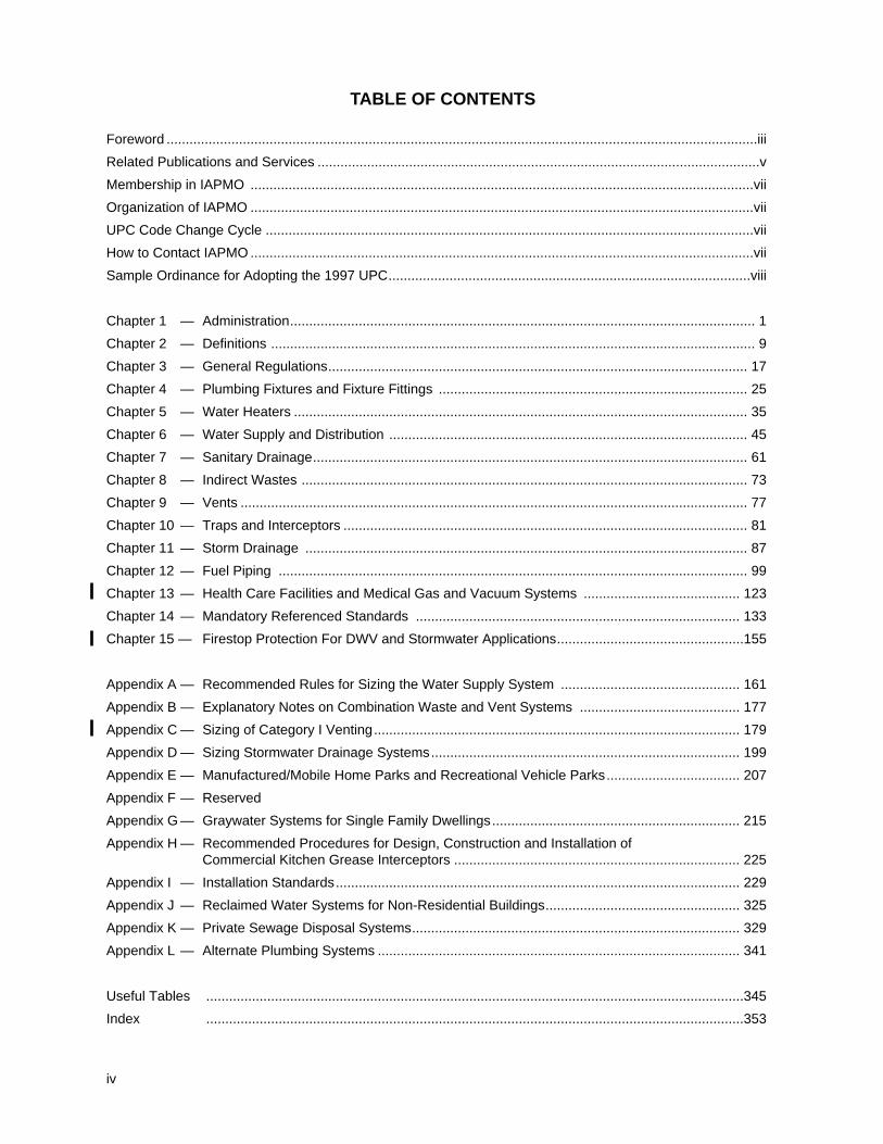
TABLE OF CONTENTS
Foreword ...........................................................................................................................................................iii
Related Publications and Services ....................................................................................................................v
Membership in IAPMO ....................................................................................................................................vii
Organization of IAPMO ....................................................................................................................................vii
UPC Code Change Cycle ................................................................................................................................vii
How to Contact IAPMO ....................................................................................................................................vii
Sample Ordinance for Adopting the 1997 UPC...............................................................................................viii
Chapter 1 — Administration.......................................................................................................................... 1
Chapter 2 — Definitions ............................................................................................................................... 9
Chapter 3 — General Regulations.............................................................................................................. 17
Chapter 4 — Plumbing Fixtures and Fixture Fittings ................................................................................. 25
Chapter 5 — Water Heaters ....................................................................................................................... 35
Chapter 6 — Water Supply and Distribution .............................................................................................. 45
Chapter 7 — Sanitary Drainage.................................................................................................................. 61
Chapter 8 — Indirect Wastes ..................................................................................................................... 73
Chapter 9 — Vents ..................................................................................................................................... 77
Chapter 10 — Traps and Interceptors .......................................................................................................... 81
Chapter 11 — Storm Drainage .................................................................................................................... 87
Chapter 12 — Fuel Piping ........................................................................................................................... 99
Chapter 13 — Health Care Facilities and Medical Gas and Vacuum Systems ......................................... 123
Chapter 14 — Mandatory Referenced Standards ..................................................................................... 133
Chapter 15 — Firestop Protection For DWV and Stormwater Applications.................................................155
Appendix A — Recommended Rules for Sizing the Water Supply System ............................................... 161
Appendix B — Explanatory Notes on Combination Waste and Vent Systems .......................................... 177
Appendix C — Sizing of Category I Venting................................................................................................ 179
Appendix D — Sizing Stormwater Drainage Systems................................................................................. 199
Appendix E — Manufactured/Mobile Home Parks and Recreational Vehicle Parks................................... 207
Appendix F — Reserved
Appendix G — Graywater Systems for Single Family Dwellings................................................................. 215
Appendix H — Recommended Procedures for Design, Construction and Installation ofCommercial Kitchen Grease Interceptors ........................................................................... 225
Appendix I — Installation Standards.......................................................................................................... 229
Appendix J — Reclaimed Water Systems for Non-Residential Buildings................................................... 325
Appendix K — Private Sewage Disposal Systems...................................................................................... 329
Appendix L — Alternate Plumbing Systems ............................................................................................... 341
Useful Tables .............................................................................................................................................345
Index .............................................................................................................................................353
iv
RELATED PUBLICATIONS AND SERVICESIAPMO provides a variety of other products which are useful for inspectors, building officials, architects,engineers, manufacturers, contractors, plumbers, and apprentices.
IAPMO ORDER DESK20001 WALNUT DRIVE SOUTH
WALNUT, CA 91789-2825PHONE: 909-595-8449, EXT. 113, FAX: 909-594-3690
FOR PUBLICATIONS ORDERS: 800-85-IAPMO
Uniform Plumbing Code — Spanish Edition:This UPC will assist the Spanish-speaking community in its utilization of the most widely adopted plumbingcode in the world. The UPC was translated in response to numerous requests from jurisdictionsthroughout the US with large Spanish-speaking populations.
Uniform Plumbing Code on CD Rom:With this CD, the Code is fully indexed and searchable, making it easy to get to the critical information youneed without leafing through bulky books or dealing with torn pages.
Uniform Plumbing Code Interpretations Manual:This increasingly popular manual is the result of ongoing work by IAPMO’s Code InterpretationsCommittee. Updated annually, it contains hundreds of questions and answers. Many of these questionsarise in the daily administration and enforcement of the code. Interpretation requests are accepted fromactive IAPMO members. Interpretation Request Forms are available in Official magazine or from IAPMO.
Uniform Plumbing Code Illustrated Training Manual:The UPC Illustrated Training Manual is an excellent reference for anyone involved in the plumbingindustry. It has an extensive definitions section and several hundred comprehensive technical diagramsand illustrations. It serves as a textbook, and it also is useful as a valuable tool for explaining the intentand use of the Code.
Uniform Plumbing Code Study Guide:This book is the perfect complement to the UPC Illustrated Training Manual. Alone, it constitutes a completechapter-by-chapter self-study course for learning the UPC. It has hundreds of questions, general practiceexams, a section on plumbing math, numerous pipe sizing exercises, and a section on fitting identification.The questions and answers in the UPC Study Guide are kept current by IAPMO’s Education Committee.
Dwelling Requirements of the Uniform Plumbing Code:This books contains the UPC requirements which apply to one and two family dwellings only. Its illustrationsand photographs make it especially useful for combination dwelling inspectors and the do-it-yourselfer.
Cumulative Analysis of Uniform Plumbing Code Changes:An excellent reference for learning and understanding plumbing code changes adopted at the AnnualEducation and Business Conferences. It is also useful for parties preparing proposed code changes.
Uniform Mechanical CodeThe Uniform Mechanical Code contains complete requirements for the installation and maintenance ofheating, ventilating, cooling, and refrigeration systems.
Uniform Mechanical Code Study Guide:Similar in design to the Uniform Plumbing Code Study Guide, the Uniform Mechanical Code Study Guidecovers all aspects of the UMC in detail.
Handbook to the Uniform Mechanical CodeAn indispensable tool for understanding the provisions of the Uniform Mechanical Code.
v
Uniform Solar Energy Code:Provides a complete set of regulations for the use of solar energy in both plumbing and mechanical systems.
Uniform Swimming Pool, Spa, and Hot Tub Code:Contains complete and current guidelines for piping systems serving these increasingly popular amenities.
IAPMO Installation Standards:IAPMO standards committees have formulated installation standards for a wide variety of commonly usedplumbing materials and systems. The IAPMO installation standards are included after the text of theUniform Plumbing Code. Separate printed copies are also available.
Material and Property Standards:Although IAPMO does not generally develop material and property standards, when it becomes apparentthat necessary standards are nonexistent, IAPMO has exercised leadership by developing them. IAPMO’sstandards are always subject to modifications and improvements, and are withdrawn when acceptablenationally-recognized consensus standards are formulated.
Manufactured Home and Recreational Vehicle Standards:Similar to the material and property standards, IAPMO has developed a number of standards for specialtyproducts used in manufactured homes and recreational vehicles. These standards are availableindividually, or they may be purchased as a set.
ANSI Z 124 Standards:These standards are written to specifically address a variety of plastic plumbing fixtures and components.They are available individually, or may be grouped for quantity discounts.
Directory of Listed Plumbing Products:The IAPMO R&T Listing Program was primarily created to benefit the building and plumbing officials in thegrowing number of jurisdictions that adopt and use the UPC. For a product to be listed by IAPMO R&T, itmust be found to be in conformance with an accepted standard or criteria and must not be in conflict withthe UPC. IAPMO R&T administers a listing compliance program with unannounced inspections ofmanufacturing facilities, conducted to verify compliance with listing requirements.
This directory contains information on several thousand IAPMO R&T listed plumbing products and isupdated monthly.
Directory of Listed Plumbing Products for Manufactured Housing and Recreational Vehicles:This directory contains information on several hundred IAPMO R&T listed plumbing products used inmanufactured housing and recreational vehicles and is updated bi-monthly.
Official Magazine:IAPMO’s bimonthly publication features informative articles on plumbing, local chapter proceedings andevents, and plumbing industry updates. All IAPMO members receive a free subscription.
Drain Waste and Vent Calculator:This calculator provides quick and simple access to the fixture unit and sizing tables of Chapter 7 of the UPC.
Water Sizing Calculator:Sizing water systems becomes a much simpler task with the use of this handy calculator.
Natural Gas Pipe Sizing Calculator:Designed for systems with a supply pressure of six to eight inches of water column, all pipe capacities aregiven in cubic feet per hour.
vi
MEMBERSHIP IN IAPMOIAPMO is an open association. Membership categories have annual dues from $10.00 to $300.00. Memberbenefits include discounted prices on most IAPMO publications, a subscription to Official magazine, and theopportunity to participate in updating and improving the most comprehensive plumbing code available.
Some membership categories include additional benefits. For additional information, contact IAPMO’sMembership Department.
ORGANIZATION OF IAPMOIAPMO is a nonprofit association governed by a Board of Directors, consisting of a President, Vice President,Immediate Past President, and nine Directors. The Board of Directors is elected by the active members at theAnnual Education and Business Conference. The President and Vice President serve one year terms. TheDirectors serve for three years. A Secretary and Treasurer are appointed annually from the active membershipby the Board of Directors.
The daily business of the association is conducted by IAPMO’s staff, in coordination with IAPMO’sstanding and ad hoc committees.
UPC CODE CHANGE CYCLEFor the first time in IAPMO’s long history, the 2003 edition of the Uniform Plumbing Code (UPC) will bedeveloped utilizing a consensus process. The UPC will be harmonized with the Uniform Mechanical Code(UMC) and with the National Fire Protection Associations’ National Electrical Code, Life Safety Code and FireCode.
HOW TO CONTACT IAPMOMailing Address: Phone Numbers: Office Hours:
20001 Walnut Drive South 909-595-8449 Monday through FridayWalnut, CA 91789-2825 Fax: 909-594-3690 8:00 am to 5:00 pm Pacific time
Publications orders: Closed weekends and holidaysInternet Information: 1-800-85-IAPMO
Web Site: http://www.iapmo.orgE-Mail Address: [email protected]
vii
Sample Ordinance for Adoption of the 2000 Uniform Plumbing CodeOrdinance No.
An ordinance of the (jurisdiction) adopting the 2000 edition of the “Uniform Plumbing Code", includingIAPMO Installations Standards contained in Appendix I, regulating and controlling the design, construction,quality of materials, erection, installation, alteration, repair, location, relocation, replacement, addition to, use ormaintenance of any plumbing system in the (jurisdiction) ; providing for the issuance of permits andcollection of fees therefore; repealing Ordinance No. _____ of the (jurisdiction) and all other ordinancesand parts of the ordinances in conflict therewith.
The (governing body) of the (jurisdiction) does ordain as follows:
Section 1. That certain documents, three (3) copies of which are on file in the office of the (jurisdiction’skeeper of records) and the (jurisdiction) , being marked and designated as “Uniform Plumbing Code”,(including Appendix chapters (fill in the applicable Appendix chapters) be and are hereby adopted as thecode of the (jurisdiction) for regulating the design, construction, quality of materials, erection, installation,alteration, repair, location, relocation, replacement, addition to, use or maintenance of plumbing systems in the(jurisdiction) providing for the issuance of permits and collection of fees therefore; and each and all of theregulations, provisions, conditions and terms of such “Uniform Plumbing Code”, 2000 edition, and Appendix Ipublished by the International Association of Plumbing and Mechanical Officials, on file in the office of the(jurisdiction) are hereby referred to, adopted and made a part hereof as if fully set out in this ordinance.
Section 2. (Incorporate penalties for violations. See Section 102.3.2.)
Section 3. That Ordinance No. of (jurisdiction) entitled (fill in here the complete title of the presentplumbing ordinance or ordinances in effect at the present time so that they will be repealed by definitemention) and all other ordinances or parts of ordinances in conflict herewith are hereby repealed.
Section 4. That if any section, subsection, sentence, clause or phrase of this ordinance is, for any reason, heldto be unconstitutional, such decision shall not affect the validity of the remaining portions of this ordinance. The(governing body) hereby declares that it would have passed this ordinance, each section, subsection, clauseor phrase thereof, irrespective of the fact that any one or more sections, subsections, sentences, clauses andphrases be declared unconstitutional.
Section 5. That the (jurisdiction’s keeper of records) is hereby ordered and directed to cause thisordinance to be published. (An additional provision may be required to direct the number of times theordinance is to be published and to specify that it is to be in a newspaper in general circulation. Posting mayalso be required.)
Section 6. That this ordinance and the rules, regulations, provisions, requirements, orders and mattersestablished and adopted hereby shall take effect and be in full force and effect (time period) from andafter the date of its final passage and adoption.
viii
101.0 Title, Scope and General
101.1 Title
This document shall be known as the “UniformPlumbing Code,’’ may be cited as such, and will bereferred to herein as “this Code.’’
101.2 Purpose
This Code is an ordinance providing minimumrequirements and standards for the protection of thepublic health, safety, and welfare.
101.3 Plans Required
The Administrative Authority may require thesubmission of plans, specifications, drawings, andsuch other information as the AdministrativeAuthority may deem necessary, prior to thecommencement of, and at any time during theprogress of any work regulated by this Code.
The issuance of a permit upon plans andspecifications shall not prevent the AdministrativeAuthority from thereafter requiring the correction oferrors in said plans and specifications or frompreventing construction operations being carried onthereunder when in violation of this Code or of anyother pertinent ordinance or from revoking anycertificate of approval when issued in error.
101.4 Scope
101.4.1 The provisions of this Code shall applyto the erection, installation, alteration, repair,relocation, replacement, addition to, use ormaintenance of plumbing systems within thisjurisdiction.
101.4.1.1 Repairs and Alterations
101.4.1.1.1 In existing buildings orpremises in which plumbinginstallations are to be altered, repaired,or renovated, deviations from theprovisions of this Code are permitted,provided such deviations are found tobe necessary and are first approved bythe Administrative Authority.
101.4.1.1.2 Existing building sewersand building drains may be used inconnection with new buildings or newplumbing and drainage work onlywhen they are found on examinationand test to conform in all respects to therequirements governing new work, andthe proper Administrative Authorityshall notify the owner to make any
changes necessary to conform to thisCode. No building or part thereof, shallbe erected or placed over any part of adrainage system which is constructed ofmaterials other than those approvedelsewhere in this Code for use under orwithin a building.
101.4.1.1.3 All openings into adrainage or vent system, exceptingthose openings to which plumbingfixtures are properly connected orwhich constitute vent terminals, shall bepermanently plugged or capped in anapproved manner, using theappropriate materials required by thisCode.
101.4.1.2 Maintenance. The plumbing anddrainage system of any premises under thejurisdiction of the Administrative Authorityshall be maintained in a sanitary and safeoperating condition by the owner or theowner’s agent.
101.4.1.3 Existing Construction. Noprovision of this Code shall be deemed torequire a change in any portion of aplumbing or drainage system or any otherwork regulated by this Code in or on anexisting building or lot when such work wasinstalled and is maintained in accordancewith law in effect prior to the effective dateof this Code, except when any suchplumbing or drainage system or other workregulated by this Code is determined by theAdministrative Authority to be in factdangerous, unsafe, insanitary, or a nuisanceand a menace to life, health, or property.
101.4.1.4 Conflicts Between Codes.When the requirements within thejurisdiction of this plumbing code conflictwith the requirements of the mechanicalcode, this code shall prevail.
101.4.2 Additions, alterations, repairs andreplacement of plumbing systems shall complywith the provisions for new systems except asotherwise provided in Section 101.5.
101.4.3 The provisions in the appendices areintended to supplement the requirements of thisCode and shall not be considered part of thisCode unless formally adopted as such.
1
CHAPTER 1
ADMINISTRATION
101.5 Application to Existing Plumbing System
101.5.1 Additions, Alterations or Repairs.Additions, alterations or repairs may be made toany plumbing system without requiring theexisting plumbing system to comply with all therequirements of this Code, provided the addition,alteration or repair conforms to that required for anew plumbing system. Additions, alterations orrepairs shall not cause an existing system tobecome unsafe, insanitary or overloaded.101.5.2 Health and Safety. Whenevercompliance with all the provisions of this Codefails to eliminate or alleviate a nuisance, or anyother dangerous or insanitary condition whichmay involve health or safety hazards, the owneror the owner's agent shall install such additionalplumbing and drainage facilities or shall makesuch repairs or alterations as may be ordered bythe Administrative Authority.101.5.3 Existing Installation. Plumbingsystems lawfully in existence at the time of theadoption of this Code may have their use,maintenance or repair continued if the use,maintenance or repair is in accordance with theoriginal design and location and no hazard tolife, health or property has been created by suchplumbing system.101.5.4 Changes in Building Occupancy.Plumbing systems which are a part of any buildingor structure undergoing a change in use oroccupancy, as defined in the Building Code, shallcomply to all requirements of this Code whichmay be applicable to the new use or occupancy.101.5.5 Maintenance. All plumbing systems,materials and appurtenances, both existing andnew, and all parts thereof shall be maintained inproper operating condition. All devices orsafeguards required by this Code shall bemaintained in conformance with the Codeedition under which installed. The owner or theowner’s designated agent shall be responsiblefor maintenance of plumbing systems. Todetermine compliance with this subsection, theAdministrative Authority may cause anyplumbing system to be reinspected.101.5.6 Moved Buildings. Plumbing systemswhich are part of buildings or structures movedinto this jurisdiction shall comply with theprovisions of this Code for new installationsexcept as provided for in Section 103.5.5.2.
102.0 Organization and Enforcement102.1 Administrative AuthorityThe Administrative Authority shall be the Authorityduly appointed to enforce this Code.
102.2 Duties and Powers of the AdministrativeAuthority
102.2.1 The Administrative Authority mayappoint such assistants, deputies, inspectors, orother employees as are necessary to carry out thefunctions of the department and this Code.
102.2.2 Right of Entry. Whenever it isnecessary to make an inspection to enforce theprovisions of this Code, or whenever theAdministrative Authority has reasonable causeto believe that there exists in any building orupon any premises, any condition or violation ofthis Code which make the building or premisesunsafe, insanitary, dangerous or hazardous, theAdministrative Authority may enter the buildingor premises at all reasonable times to inspect orto perform the duties imposed upon theAdministrative Authority by this Code, providedthat if such building or premises is occupied, theAdministrative Authority shall presentcredentials to the occupant and request entry. Ifsuch building or premises is unoccupied, theAdministrative Authority shall first make areasonable effort to locate the owner or otherperson having charge or control of the buildingor premises and request entry. If entry is refused,the Administrative Authority has recourse toevery remedy provided by law to secure entry.
When the Administrative Authority shallhave first obtained a proper inspection warrantor other remedy provided by law to secureentry, no owner, occupant, or person havingcharge, care, or control of any building orpremises shall fail or neglect, after properrequest is made as herein provided, to promptlypermit entry herein by the AdministrativeAuthority for the purpose of inspection andexamination pursuant to this Code.
102.2.3 Stop Orders. Whenever any work isbeing done contrary to the provisions of thisCode, the Administrative Authority may orderthe work stopped by notice in writing served onany persons engaged in the doing or causingsuch work to be done, and any such personsshall forthwith stop work until authorized bythe Administrative Authority to proceed withthe work.
102.2.4 Authority to Disconnect Utilities inEmergencies. The Administrative Authorityshall have the authority to disconnect aplumbing system to a building, structure orequipment regulated by this Code in case ofemergency where necessary to eliminate animmediate hazard to life or property.
UNIFORM PLUMBING CODE
2
101.5 – 102.2
102.2.5 Authority to Condemn. Whenever theAdministrative Authority ascertains that anyplumbing system or portion thereof, regulatedby this Code, has become hazardous to life,health, property, or has become insanitary, theAdministrative Authority shall order in writingthat such plumbing either be removed or placedin a safe or sanitary condition, as appropriate.The order shall fix a reasonable time limit forcompliance. No person shall use or maintaindefective plumbing after receiving such notice.
When such plumbing system is to bedisconnected, written notice shall be given. Incases of immediate danger to life or property,such disconnection may be made immediatelywithout such notice.
102.2.6 Liability. The Administrative Authoritycharged with the enforcement of this Code,acting in good faith and without malice in thedischarge of the Administrative Authority’sduties, shall not thereby be rendered personallyliable for any damage that may accrue to personsor property as a result of any act or by reason ofany act or omission in the discharge of duties. Asuit brought against the AdministrativeAuthority or employee because of such act oromission performed in the enforcement of anyprovision of this Code shall be defended by legalcounsel provided by this jurisdiction until finaltermination of such proceedings.
102.3 Violations and Penalties
102.3.1 Violations. It shall be unlawful for anyperson, firm or corporation to erect, construct,enlarge, alter, repair, move, improve, remove,convert, demolish, equip, use, or maintain anyplumbing or permit the same to be done inviolation of this Code.
102.3.2 Penalties. Any person, firm, orcorporation violating any provision of this Codeshall be deemed guilty of a misdemeanor, andupon conviction thereof, shall be punishable bya fine and/or imprisonment set forth by thegoverning laws of the jurisdiction. Each separateday or any portion thereof, during which anyviolation of this Code occurs or continues, shallbe deemed to constitute a separate offense.
103.0 Permits and Inspections
103.1 Permits
103.1.1 Permits Required. It shall be unlawfulfor any person, firm or corporation to make anyinstallation, alteration, repair, replacement orremodel any plumbing system regulated by thisCode except as permitted in Section 103.1.2, or to
cause the same to be done without firstobtaining a separate plumbing permit for eachseparate building or structure.
103.1.2 Exempt Work. A permit shall not berequired for the following:
103.1.2.1 The stopping of leaks in drains,soil, waste or vent pipe, provided, however,that should any trap, drainpipe, soil, wasteor vent pipe become defective and itbecomes necessary to remove and replacethe same with new material, the same shallbe considered as new work and a permitshall be procured and inspection made asprovided in this Code.
103.1.2.2 (1) The clearing of stoppages,including the removal and reinstallation ofwater closets or;
(2) the repairing of leaks in pipes, valves orfixtures, provided such repairs do notinvolve or require the replacement orrearrangement of valves, pipes, or fixtures.
Exemption from the permitrequirements of this Code shall not bedeemed to grant authorization for any workto be done in violation of the provisions ofthe Code or any other laws or ordinances ofthis jurisdiction.
103.1.3 Licensing. As a result of an agreementbetween the Department of Housing and UrbanDevelopment (HUD) and IAPMO the requirementsfor licensing have been removed from this sectionof the UPC. Provision for l icensing shall bedetermined by the Administrative Authority.
103.2 Application For Permit
103.2.1 Application. To obtain a permit, theapplicant shall first file an application therefor inwriting on a form furnished by theAdministrative Authority for that purpose.Every such application shall:
103.2.1.1 Identify and describe the work tobe covered by the permit for whichapplication is made.
103.2.1.2 Describe the land upon whichthe proposed work is to be done by legaldescription, street address or similardescription that will readily identify anddefinitely locate the proposed building orwork.
103.2.1.3 Indicate the use or occupancy forwhich the proposed work is intended.
103.2.1.4 Be accompanied by plans,diagrams, computations and other data asrequired in Section 103.2.2.
ADMINISTRATION 102.2 – 103.2
3
103.2.1.5 Be signed by permittee or thepermittee’s authorized agent, who may berequired to submit evidence to indicate suchauthority.103.2.1.6 Give such other data andinformation as may be required by theAdministrative Authority.
103.2.2 Plans and Specifications. Plans,engineering calculations, diagrams and otherdata shall be submitted in one or more sets witheach application for a permit. The AdministrativeAuthority may require plans, computations andspecifications to be prepared by and theplumbing designed by an engineer and/orarchitect licensed by the state to practice as such.
Exception: The Administrative Authoritymay waive the submission of plans,calculations or other data if theAdministrative Authority finds that thenature of the work applied for is such thatreviewing of plans is not necessary to obtaincompliance within the Code.
103.2.3 Information on Plans andSpecifications. Plans and specifications shall bedrawn to scale upon substantial paper or clothand shall be of sufficient clarity to indicate thelocation, nature and extent of the work proposedand show in detail that it will conform to theprovisions of this Code and relevant laws,ordinances, rules and regulations.
103.3 Permit Issuance
103.3.1 Issuance. The application, plans andspecifications and other data filed by anapplicant for a permit shall be reviewed by theAdministrative Authority. Such plans may bereviewed by other departments of thisjurisdiction to verify compliance with applicablelaws under their jurisdiction. If theAdministrative Authority finds that the workdescribed in an application for permit and theplans, specifications and other data filedtherewith conform to the requirements of thecode and other pertinent laws and ordinances,and that the fees specified in Section 103.4 havebeen paid, the Administrative Authority shallissue a permit therefor to the applicant.
When the Administrative Authority issuesthe permit where plans are required, theAdministrative Authority shall endorse inwriting or stamp the plans and specifications“APPROVED”. Such approved plans andspecifications shall not be changed, modified oraltered without authorization from theAdministrative Authority and all work shall bedone in accordance with approved plans.
The Administrative Authority may issue apermit for the construction of a part of aplumbing system before the entire plans andspecifications for the whole system have beensubmitted or approved, provided adequateinformation and detailed statements have beenfiled complying with all pertinent requirementsof this Code. The holder of such permit mayproceed at the holder’s risk without assurancethat the permit for the entire building, structureor plumbing system will be granted.103.3.2 Retention of Plans. One set ofapproved plans, specifications and computationsshall be retained by the AdministrativeAuthority until final approval of the workcovered therein. One set of approved plans andspecifications shall be returned to the applicant,and said set shall be kept on the site of thebuilding or work at all times during which thework authorized thereby is in progress.103.3.3 Validity of Permit. The issuance of apermit or approval of plans and specificationsshall not be construed to be a permit for, or anapproval of, any violation of any of theprovisions of this Code or of any otherordinance of the jurisdiction. No permitpresuming to give authority to violate or cancelthe provisions of this Code shall be valid.
The issuance of a permit based upon plans,specifications or other data shall not prevent theAdministrative Authority from thereafterrequiring the correction of errors in said plans,specifications and other data or from preventingbuilding operations being carried on thereunderwhen in violation of this Code or of otherordinances of this jurisdiction.103.3.4 Expiration. Every permit issued by theAdministrative Authority under the provisionsof this Code shall expire by limitation andbecome null and void if the work authorized bysuch permit is not commenced within onehundred eighty (180) days from the date of suchpermit, or if the work authorized by such permitis suspended or abandoned at any time after thework is commenced for a period of one hundredeighty (180) days. Before such work can berecommenced, a new permit shall first beobtained to do so, and the fee therefor shall beone-half the amount required for a new permitfor such work, provided no changes have beenmade or will be made in the original plans andspecifications for such work, and providedfurther, that such suspensions or abandonmenthas not exceeded one year.
Any permittee holding an unexpired permit
UNIFORM PLUMBING CODE
4
103.2 – 103.3
may apply for an extension of the time withinwhich work may commence under that permitwhen the permittee is unable to commence workwithin the time required by this section for goodand satisfactory reasons. The AdministrativeAuthority may extend the time for action by thepermittee for a period not exceeding onehundred eighty (180) days upon written requestby the permittee showing that circumstancesbeyond the control of the permittee haveprevented action from being taken. No permitshall be extended more than once. In order torenew action on a permit after expiration, thepermittee shall pay a new full permit fee.103.3.5 Suspension or Revocation. TheAdministrative Authority may, in writing,suspend or revoke a permit issued under theprovisions of this Code whenever the permit isissued in error or on the basis of incorrectinformation supplied or in violation of otherordinance or regulation of the jurisdiction.
103.4 Fees
103.4.1 Permit Fees. Fees shall be assessed inaccordance with the provisions of this sectionand as set forth in the fee schedule Table 1-1. Thefees are to be determined and adopted by thisjurisdiction.103.4.2 Plan Review Fees. When a plan orother data is required to be submitted by 103.2.2,a plan review fee shall be paid at the time ofsubmitting plans and specifications for review.The plan review fees for plumbing work shall bedetermined and adopted by this jurisdiction.
The plan review fees specified in thissubsection are separate fees from the permit feesspecified in this section and are in addition tothe permit fees.
When plans are incomplete or changed so asto require additional review, a fee shall becharged at the rate shown in Table 1-1.103.4.3 Expiration of Plan Review.Applications for which no permit is issuedwithin one hundred eighty (180) days followingthe date of application shall expire by limitationand plans and other data submitted for reviewmay thereafter be returned to the applicant ordestroyed by the Administrative Authority. TheAdministrative Authority may exceed the timefor action by the applicant for a period not toexceed one hundred eighty (180) days uponrequest by the applicant showing thatcircumstances beyond the control of theapplicant have prevented action from beingtaken. No application shall be extended morethan once. In order to renew action on an
application after expiration, the applicant shallresubmit plans and pay a new plan review fee.103.4.4 Investigation Fees: Work Without aPermit
103.4.4.1 Whenever any work for which apermit is required by this Code has beencommenced without first obtaining saidpermit, a special investigation shall be madebefore a permit may be issued for such work.103.4.4.2 An investigation fee, in additionto the permit fee, shall be collected whetheror not a permit is then or subsequentlyissued. The investigation fee shall be equalto the amount of the permit fee that wouldbe required by this Code if a permit were tobe issued. The payment of suchinvestigation fee shall not exempt anyperson from compliance with all otherprovisions of this Code, nor from anypenalty prescribed by law.
103.4.5 Fee Refunds
103.4.5.1 The Administrative Authoritymay authorize the refunding of any fee paidhereunder which was erroneously paid orcollected.103.4.5.2 The Administrative Authoritymay authorize the refunding of not morethan a percentage, as determined by thisjurisdiction when no work has been doneunder a permit issued in accordance withthis Code.103.4.5.3 The Administrative Authority mayauthorize the refunding of not more than apercentage, as determined by this jurisdictionwhen no work has been done under a permitissued in accordance with this Code.
The Administrative Authority shall notauthorize the refunding of any fee paidexcept upon written application filed by theoriginal permittee not later than onehundred eighty (180) days after the date offee payment.
103.5 Inspections
103.5.1 General. All plumbing systems forwhich a permit is required by this Code shall beinspected by the Administrative Authority. Noportion of any plumbing system shall beconcealed until inspected and approved. Neitherthe Administrative Authority nor thejurisdiction shall be liable for expense entailed inthe removal or replacement of material requiredto permit inspection. When the installation of aplumbing system is complete, an additional andfinal inspection shall be made. Plumbing
ADMINISTRATION 103.3 – 103.5
5
systems regulated by this Code shall not beconnected to the water, energy fuel supply, orthe sewer system until authorized by theAdministrative Authority.
103.5.1.1 Inspection. No water supplysystem or portion thereof, shall be coveredor concealed until it first has been tested,inspected, and approved.103.5.1.2 Scope. All new plumbing workand such portions of existing systems asmay be affected by new work, or anychanges, shall be inspected by theAdministrative Authority to insurecompliance with all the requirements of thisCode and to assure that the installation andconstruction of the plumbing system is inaccordance with approved plans.103.5.1.3 Covering or Using. Noplumbing or drainage system, buildingsewer, private sewer disposal system or partthereof, shall be covered, concealed, or putinto use until it has been tested, inspected,and accepted as prescribed in this Code.103.5.1.4 Uncovering. Any drainage orplumbing system, building sewer, privatesewage disposal system, or part thereof,which is installed, altered, or repaired iscovered or concealed before being inspected,tested, and approved as prescribed in thisCode, it shall be uncovered for inspectionafter notice to uncover the work has beenissued to the responsible person by theAdministrative Authority.
103.5.2 Operation of Plumbing Equipment.The requirements of this section shall not beconsidered to prohibit the operation of anyplumbing installed to replace existingequipment or fixtures serving an occupiedportion of the building in the event a request forinspection of such equipment or fixture has beenfiled with the Administrative Authority notmore than seventy-two (72) hours after suchreplacement work is completed, and before anyportion of such plumbing system is concealed byany permanent portion of the building.103.5.3 Testing of Systems. All plumbingsystems shall be tested and approved as requiredby this Code or the Administrative Authority.
103.5.3.1 Test. Tests shall be conducted inthe presence of the AdministrativeAuthority or the Administrative Authority'sduly appointed representative.103.5.3.2 Test Waived. No test orinspection shall be required where a
plumbing system, or part thereof, is set upfor exhibition purposes and has noconnection with a water or drainage system.103.5.3.3 Exceptions. In cases where itwould be impractical to provide therequired water or air tests, or for minorinstallations and repairs, the AdministrativeAuthority may make such inspection asdeemed advisable in order to be assuredthat the work has been performed inaccordance with the intent of this Code.103.5.3.4 Protectively Coated Pipe.Protectively coated pipe shall be inspectedand tested, and any visible void, damage orimperfection to the pipe coating shall berepaired to comply with Section 313.0 (seeIAPMO IS-13, listed in Appendix I).103.5.3.5 Tightness. Joints andconnections in the plumbing system shall begastight and watertight for the pressuresrequired by test.
103.5.4 Inspection Requests. It shall be theduty of the person doing the work authorized bya permit to notify the Administrative Authoritythat such work is ready for inspection. TheAdministrative Authority may require thatevery request for inspection be filed at least oneworking day before such inspection is desired.Such request may be in writing or by telephone,at the option of the Administrative Authority.
It shall be the duty of the person requestinginspections required by this Code to provideaccess to and means for proper inspection ofsuch work.
103.5.4.1 Advance Notice. It shall be theduty of the person doing the workauthorized by the permit to notify theAdministrative Authority, orally or inwriting, that said work is ready forinspection. Such notification shall be givennot less than twenty-four (24) hours beforethe work is to be inspected.103.5.4.2 Responsibility. It shall be theduty of the holder of a permit to make surethat the work will stand the test prescribedbefore giving the notification.
The equipment, material, and labornecessary for inspection or tests shall befurnished by the person to whom the permitis issued or by whom inspection isrequested.
103.5.5 Other Inspections. In addition to theinspections required by this Code, theAdministrative Authority may require other
UNIFORM PLUMBING CODE
6
103.5
inspections of any plumbing work to ascertaincompliance with the provisions of this Code andother laws which are enforced by theAdministrative Authority.
103.5.5.1 Defective Systems. An air testshall be used in testing the sanitarycondition of the drainage or plumbingsystem of any building premises when thereis reason to believe that it has becomedefective. In buildings or premisescondemned by the proper AdministrativeAuthority because of an insanitary conditionof the plumbing system or part thereof, thealterations in such system shall conform tothe requirements of this Code.103.5.5.2 Moved Structures. All parts ofthe plumbing systems of any building orpart thereof that is moved from onefoundation to another, or from one locationto another, shall be completely tested asprescribed elsewhere in this section for newwork, except that walls or floors need not beremoved during such test when otherequivalent means of inspection acceptable tothe Administrative Authority are provided.
103.5.6 Reinspections. A reinspection fee maybe assessed for each inspection or reinspectionwhen such portion of work for which inspectionis called is not complete or when requiredcorrections have not been made.
This provision is not to be interpreted asrequiring reinspection fees the first time a job isrejected for failure to comply with therequirements of this Code, but as controlling thepractice of calling for inspections before the jobis ready for inspection or reinspection.
Reinspection fees may be assessed when theapproved plans are not readily available to theinspector, for failure to provide access on thedate for which the inspection is requested, or fordeviating from plans requiring the approval ofthe Administrative Authority.
To obtain reinspection, the applicant shallfile an application therefor in writing upon aform furnished for that purpose and pay thereinspection fee in accordance with Table 1-1.
In instances where reinspection fees havebeen assessed, no additional inspection of thework will be performed until the required feeshave been paid.
103.5.6.1 Corrections. Notices ofcorrection or violation shall be written bythe Administrative Authority and may beposted at the site of the work or mailed or
delivered to the permittee or his authorizedrepresentative. Refusal, failure, or neglect tocomply with any such notice or order withinten (10) days of receipt thereof, shall beconsidered a violation of this Code, andshall be subject to the penalties set forthelsewhere in this Code for violations.103.5.6.2 Retesting. If the AdministrativeAuthority finds that the work will not passthe test, necessary corrections shall be madeand the work shall then be resubmitted fortest or inspection.103.5.6.3 Approval. Upon the satisfactorycompletion and final test of the plumbingsystem, a certificate of approval shall beissued by the Administrative Authority tothe permittee on demand.
103.6 Connection Approval
103.6.1 Energy Connections. No person shallmake connections from a source of energy or fuelto any plumbing system or equipment regulatedby this Code and for which a permit is requireduntil approved by the Administrative Authority.103.6.2 Other Connections. No person shallmake connection from any water-supply line norshall connect to any sewer system regulated bythis Code and for which a permit is requireduntil approved by the Administrative Authority.103.6.3 Temporary Connections. TheAdministrative Authority may authorizetemporary connection of the plumbingequipment to the source of energy or fuel for thepurpose of testing the equipment.
103.7 Unconstitutionality
103.7.1 If any section, subsection, sentence,clause, or phrase of this Code is, for any reason,held to be unconstitutional, such decision shallnot affect the validity of the remaining portions ofthis Code. The Legislative Body hereby declaresthat it would have passed this Code, and eachsection, subsection, sentence, clause, or phrasethereof, irrespective of the fact that any one ormore sections, subsections, sentences, clauses,and phrases be declared unconstitutional.
103.8 Validity
103.8.1 If any provision of this Code, or theapplication thereof to any person orcircumstance, is held invalid, the remainder ofthe Code, or the application of such provision toother persons or circumstances, shall not beaffected thereby.103.8.2 Wherever in this Code reference is madeto an appendix, the provisions in the appendixshall not apply unless specifically adopted.
ADMINISTRATION 103.5 – 103.8
7
UNIFORM PLUMBING CODE
8
Table 1-1
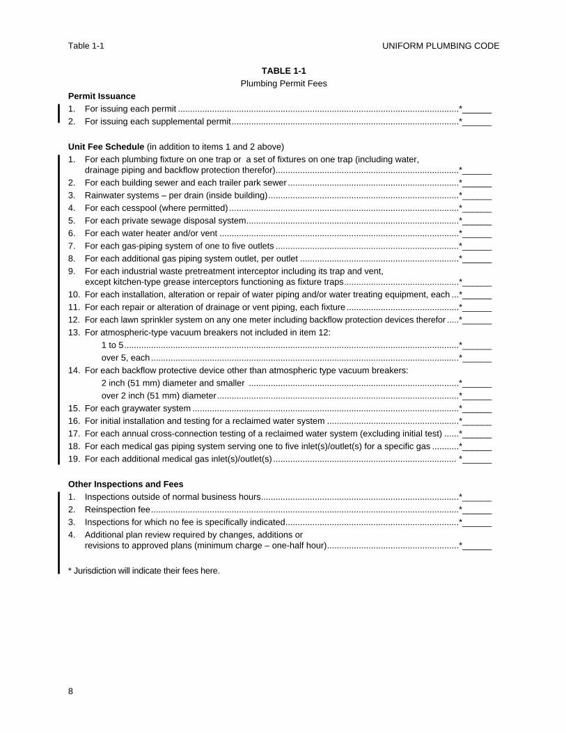
TABLE 1-1Plumbing Permit Fees
Permit Issuance1. For issuing each permit ...................................................................................................................*______2. For issuing each supplemental permit.............................................................................................*______
Unit Fee Schedule (in addition to items 1 and 2 above)1. For each plumbing fixture on one trap or a set of fixtures on one trap (including water,
drainage piping and backflow protection therefor)...........................................................................*______2. For each building sewer and each trailer park sewer ......................................................................*______3. Rainwater systems – per drain (inside building)..............................................................................*______4. For each cesspool (where permitted) ..............................................................................................*______5. For each private sewage disposal system.......................................................................................*______6. For each water heater and/or vent ..................................................................................................*______7. For each gas-piping system of one to five outlets ...........................................................................*______8. For each additional gas piping system outlet, per outlet .................................................................*______9. For each industrial waste pretreatment interceptor including its trap and vent,
except kitchen-type grease interceptors functioning as fixture traps...............................................*______10. For each installation, alteration or repair of water piping and/or water treating equipment, each ...*______11. For each repair or alteration of drainage or vent piping, each fixture ..............................................*______12. For each lawn sprinkler system on any one meter including backflow protection devices therefor .....*______13. For atmospheric-type vacuum breakers not included in item 12:
1 to 5.........................................................................................................................................*______over 5, each ..............................................................................................................................*______
14. For each backflow protective device other than atmospheric type vacuum breakers:2 inch (51 mm) diameter and smaller ......................................................................................*______over 2 inch (51 mm) diameter...................................................................................................*______
15. For each graywater system .............................................................................................................*______16. For initial installation and testing for a reclaimed water system ......................................................*______17. For each annual cross-connection testing of a reclaimed water system (excluding initial test) ......*______18. For each medical gas piping system serving one to five inlet(s)/outlet(s) for a specific gas ...........*______19. For each additional medical gas inlet(s)/outlet(s) ........................................................................... *______
Other Inspections and Fees1. Inspections outside of normal business hours.................................................................................*______2. Reinspection fee..............................................................................................................................*______3. Inspections for which no fee is specifically indicated.......................................................................*______4. Additional plan review required by changes, additions or
revisions to approved plans (minimum charge – one-half hour)......................................................*______
* Jurisdiction will indicate their fees here.
201.0 General
For the purpose of this Code, the following termshave the meanings indicated in this chapter.
No attempt is made to define ordinary wordswhich are used in accordance with their establisheddictionary meanings, except where a word has beenused loosely and it is necessary to define its meaningas used in this Code to avoid misunderstanding.
The definitions of terms are arrangedalphabetically according to the first word of theterm.
202.0 Definition of Terms
203.0 – A –
ABS – Acrylonitrile-Butadiene-Styrene.
Accessible – When applied to a fixture, connection,appliance, or equipment, “accessible” means havingaccess thereto, but which first may require theremoval of an access panel, door, or similarobstruction. “Readily accessible” means direct accesswithout the necessity of removing any panel, door,or similar obstruction.
Administrative Authority – The individual official,board, department, or agency established andauthorized by a state, county, city, or other politicalsubdivision created by law to administer and enforcethe provisions of the plumbing code as adopted oramended. This definition shall include theAdministrative Authority’s duly authorizedrepresentative.
Airbreak – A physical separation which may be alow inlet into the indirect waste receptor from thefixture, appliance, or device indirectly connected.
Air Chamber – A pressure surge-absorbing deviceoperating through the compressibility of air.
Airgap, Drainage – The unobstructed verticaldistance through the free atmosphere between thelowest opening from any pipe, plumbing fixture,appliance or appurtenance conveying waste to theflood level rim of the receptor.
Airgap, Water Distribution – The unobstructedvertical distance through the free atmospherebetween the lowest opening from any pipe or faucetconveying potable water to the flood level rim of anytank, vat or fixture.
Anchors – See Supports.
Approved – Accepted or acceptable under anapplicable specification or standard stated or cited inthis Code, or accepted as suitable for the proposeduse under procedures and authority of theAdministrative Authority.
Approved Testing Agency – An organizationprimarily established for purposes of testing toapproved standards and approved by theAdministrative Authority.
Area Drain – A receptor designed to collect surfaceor storm water from an open area.
Aspirator – A fitting or device supplied with wateror other fluid under positive pressure which passesthrough an integral orifice or constriction, causing avacuum.
204.0 – B –
Backflow – The flow of water or other liquids,mixtures, or substances into the distributing pipes ofa potable supply of water from any sources otherthan its intended source. See Back-Siphonage, Back-Pressure Backflow.
Backflow Connection – Any arrangement wherebybackflow can occur.
Back-Pressure Backflow – Backflow due to anincreased pressure above the supply pressure, whichmay be due to pumps, boilers, gravity or othersources of pressure.
Backflow Preventer – A device or means to preventbackflow into the potable water system.
Back-Siphonage – The flowing back of used,contaminated, or polluted water from a plumbingfixture or vessel into a water supply pipe due to apressure less than atmospheric in such pipe. SeeBackflow.
Backwater Valve – A device installed in a drainagesystem to prevent reverse flow.
Bathroom – A room equipped with a shower orbathtub.
Battery of Fixtures – Any group of two (2) or moresimilar, adjacent fixtures which discharge into acommon horizontal waste or soil branch.
Boiler Blowoff – An outlet on a boiler to permitemptying or discharge of sediment.
Branch – Any part of the piping system other than amain, riser, or stack.
Branch, Fixture – See Fixture Branch.
9
CHAPTER 2
DEFINITIONS
Branch, Horizontal – See Horizontal Branch.
Branch Vent – A vent connecting one or moreindividual vents with a vent stack or stack vent.
Building – A structure built, erected, and framed ofcomponent structural parts designed for the housing,shelter, enclosure, or support of persons, animals, orproperty of any kind.
Building Drain – That part of the lowest piping of adrainage system which receives the discharge fromsoil, waste, and other drainage pipes inside the wallsof the building and conveys it to the building sewerbeginning two (2) feet (610 mm) outside the buildingwall.
Building Drain (Sanitary) – A building drain whichconveys sewage only.
Building Drain (Storm) – A building drain whichconveys storm water or other drainage, but nosewage.
Building Sewer – That part of the horizontal pipingof a drainage system which extends from the end ofthe building drain and which receives the dischargeof the building drain and conveys it to a publicsewer, private sewer, private sewage disposalsystem, or other point of disposal.
Building Sewer (Combined) – A building sewerwhich conveys both sewage and storm water orother drainage.
Building Sewer (Sanitary) – A building sewerwhich conveys sewage only.
Building Sewer (Storm) – A building sewer whichconveys storm water or other drainage, but nosewage.
Building Subdrain – That portion of a drainagesystem which does not drain by gravity into thebuilding sewer.
Building Supply – The pipe carrying potable waterfrom the water meter or other source of water supplyto a building or other point of use or distribution onthe lot. Building supply shall also mean waterservice.
205.0 – C –
Certified Backflow Assembly Tester – A personwho has shown competence to test and maintainbackflow assemblies to the satisfaction of theAdministrative Authority having jurisdiction.
Cesspool – A lined excavation in the ground whichreceives the discharge of a drainage system or partthereof, so designed as to retain the organic matterand solids discharging therein, but permitting theliquids to seep through the bottom and sides.
Chemical Waste – See Special Wastes.
Clarifier – See Interceptor.
Clear Water Waste – Cooling water and condensatedrainage from refrigeration and air-conditioningequipment; cooled condensate from steam heatingsystems; cooled boiler blowdown water.
Clinic Sink – A sink designed primarily to receivewastes from bedpans and having a flush rim, anintegral trap with a visible trap seal, and the sameflushing and cleansing characteristics as a watercloset.
Code – This publication: Uniform Plumbing Code.
Combination Thermostatic/Pressure BalancingValve – A mixing valve which senses outlettemperature and incoming hot and cold waterpressure and compensates for fluctuations inincoming hot and cold water temperatures and/orpressures to stabilize outlet temperatures.
Combination Waste and Vent System – A speciallydesigned system of waste piping embodying thehorizontal wet venting of one or more sinks or floordrains by means of a common waste and vent pipe,adequately sized to provide free movement of airabove the flow line of the drain.
Combined Building Sewer – See Building Sewer,(Combined).
Common – That part of a plumbing system which isso designed and installed as to serve more than one(1) appliance, fixture, building, or system.
Conductor – A pipe inside the building whichconveys storm water from the roof to a storm drain,combined building sewer, or other approved point ofdisposal.
Confined Space – A room or space having a volumeless than fifty (50) cubic feet per 1000 Btu/h (1.4m3/293W) of the aggregate input rating of all fuelburning appliances installed in that space.
Contamination – An impairment of the quality ofthe potable water which creates an actual hazard tothe public health through poisoning or through thespread of disease by sewage, industrial fluids orwaste. Also defined as High Hazard.
Continuous Vent – A vertical vent that is acontinuation of the drain to which it connects.
Continuous Waste – A drain connecting thecompartments of a set of fixtures to a trap orconnecting other permitted fixtures to a common trap.
CPVC – Chlorinated Poly (Vinyl Chloride).
Critical Level – The critical level (C-L or C/L)marking on a backflow prevention device or vacuumbreaker is a point conforming to approved standardsand established by the testing laboratory (usually
UNIFORM PLUMBING CODE
10
204.0 – 205.0
stamped on the device by the manufacturer) whichdetermines the minimum elevation above the floodlevel rim of the fixture or receptor served at whichthe device may be installed. When a backflowprevention device does not bear a critical levelmarking, the bottom of the vacuum breaker,combination valve, or the bottom of any suchapproved device shall constitute the critical level.
Cross-Connection – Any connection orarrangement, physical or otherwise, between apotable water supply system and any plumbingfixture or any tank, receptor, equipment or device,through which it may be possible for non-potable,used, unclean, polluted and contaminated water, orother substances, to enter into any part of suchpotable water system under any condition.
206.0 – D –
Department Having Jurisdiction – TheAdministrative Authority, including any other lawenforcement agency affected by any provision of thisCode, whether such agency is specifically named ornot.
Developed Length – The length along the centerline of a pipe and fittings.
Diameter – Unless specifically stated, “diameter” isthe nominal diameter as designated commercially.
Domestic Sewage – The liquid and water-bornewastes derived from the ordinary living processes,free from industrial wastes, and of such character asto permit satisfactory disposal, without specialtreatment, into the public sewer or by means of aprivate sewage disposal system.
Downspout – The rainleader from the roof to thebuilding storm drain, combined building sewer, orother means of disposal located outside of thebuilding. See Conductor and Leader.
Drain – Any pipe which carries waste or water-bornewastes in a building drainage system.
Drainage System – Includes all the piping withinpublic or private premises, which conveys sewage orother liquid wastes to a legal point of disposal, butdoes not include the mains of a public sewer systemor a public sewage treatment or disposal plant.
Durham System – A soil or waste system in whichall piping is threaded pipe, tubing, or other suchrigid construction, using recessed drainage fittings tocorrespond to the types of piping.
207.0 – E –
Effective Opening – The minimum cross-sectionalarea at the point of water supply discharge measured
or expressed in terms of: (1) diameter of a circle, or(2) if the opening is not circular, or the diameter of acircle of equivalent cross-sectional area. (This isapplicable also to airgap.)
Existing Work – A plumbing system or any partthereof which has been installed prior to the effectivedate of this Code.
208.0 – F –
Fixture Branch – A water supply pipe between thefixture supply pipe and the water distributing pipe.
Fixture Drain – The drain from the trap of a fixtureto the junction of that drain with any other drainpipe.
Fixture Supply – A water supply pipe connectingthe fixture with the fixture branch.
Fixture Unit – A quantity in terms of which the load-producing effects on the plumbing system ofdifferent kinds of plumbing fixtures are expressed onsome arbitrarily chosen scale.
Flammable Vapor or Fumes is the concentration offlammable constituents in air that exceeds 25 percentof its lower flammability limit (LFL).
Flood Level – See Flooded.
Flood Level Rim – The top edge of a receptor fromwhich water overflows.
Flooded – A fixture is flooded when the liquidtherein rises to the flood level rim.
Flush Tank – A tank located above or integral withwater closets, urinals, or similar fixtures for thepurpose of flushing the usable portion of the fixture.
Flush Valve – A valve located at the bottom of atank for the purpose of flushing water closets andsimilar fixtures.
Flushometer Tank – A tank integrated within an airaccumulator vessel which is designed to discharge apredetermined quantity of water to fixtures forflushing purposes.
Flushometer Valve – A valve which discharges apredetermined quantity of water to fixtures forflushing purposes and is actuated by direct waterpressure.
209.0 – G –
Gang or Group Shower – Two or more showers in acommon area.
Grade – The slope or fall of a line of pipe inreference to a horizontal plane. In drainage, it isusually expressed as the fall in a fraction of an inch(mm) or percentage slope per foot (meter) length ofpipe.
DEFINITIONS
11
205.0 – 209.0
UNIFORM PLUMBING CODE
12
Grease Interceptor – An interceptor of at least 750gallon (2839 L) capacity to serve one (1) or morefixtures and which shall be remotely located.
Grease Trap – A device designed to retain greasefrom one (1) to a maximum of four (4) fixtures.
210.0 – H –
Hangers – See Supports.
High Hazard – See Contamination.
Horizontal Branch – A drain pipe extendinglaterally from a soil or waste stack or building drainwith or without vertical sections or branches, whichreceives the discharge from one or more fixturedrains and conducts it to the soil or waste stack or tothe building drain.
Horizontal Pipe – Any pipe or fitting which isinstalled in a horizontal position or which makes anangle of less than forty-five (45) degrees with thehorizontal.
House Drain – See Building Drain.
House Sewer – See Building Sewer.
211.0 – I –
Indirect Waste Pipe – A pipe that does not connectdirectly with the drainage system but conveys liquidwastes by discharging into a plumbing fixture,interceptor, or receptacle which is directly connectedto the drainage system.
Individual Vent – A pipe installed to vent a fixturetrap and which connects with the vent system abovethe fixture served or terminates in the open air.
Industrial Waste – Any and all liquid or water-borne waste from industrial or commercialprocesses, except domestic sewage.
Insanitary – A condition which is contrary tosanitary principles or is injurious to health.
Conditions to which “insanitary” shall applyinclude the following:
(1) Any trap which does not maintain a propertrap seal.
(2) Any opening in a drainage system, exceptwhere lawful, which is not provided with anapproved water-sealed trap.
(3) Any plumbing fixture or other wastedischarging receptor or device, which is notsupplied with water sufficient to flush andmaintain the fixture or receptor in a cleancondition.
(4) Any defective fixture, trap, pipe, or fitting.
(5) Any trap, except where in this Codeexempted, directly connected to a drainage
system, the seal of which is not protected againstsiphonage and back-pressure by a vent pipe.
(6) Any connection, cross-connection,construction or condition, temporary orpermanent, which would permit or makepossible by any means whatsoever, for anyunapproved foreign matter to enter a waterdistribution system used for domestic purposes.
(7) The foregoing enumeration of conditions towhich the term “insanitary” shall apply, shallnot preclude the application of that term toconditions that are, in fact, insanitary.
Interceptor (Clarifier) – A device designed andinstalled so as to separate and retain deleterious,hazardous, or undesirable matter from normalwastes and permit normal sewage or liquid wastes todischarge into the disposal terminal by gravity.
Invert – The lowest portion of the inside of ahorizontal pipe.
212.0 – J –
Joint, Brazed – Any joint obtained by joining ofmetal parts with alloys which melt at temperatureshigher than 840°F (449°C), but lower than themelting temperature of the parts to be joined.
Joint, Soldered – A joint obtained by the joining ofmetal parts with metallic mixtures or alloys whichmelt at a temperature up to and including 840°F(449°C).
213.0 – K –
No definitions
214.0 – L –
Labeled – Equipment or materials bearing a label ofa listing agency. See Listed.
Lavatories in Sets – Two (2) or three (3) lavatoriesthat are served by one (1) trap.
Leader – An exterior vertical drainage pipe forconveying storm water from roof or gutter drains.See Downspout.
Liquid Waste – The discharge from any fixture,appliance, or appurtenance in connection with aplumbing system which does not receive fecal matter.
Listed – Equipment or materials included in a listpublished by a listing agency that maintains periodicinspection on current production of listed equipmentor materials and whose listing states either that theequipment or material complies with approvedstandards or has been tested and found suitable foruse in a specified manner.
209.0 – 214.0
Listing Agency – An agency accepted by theAdministrative Authority which is in the business oflisting or labeling and which maintains a periodicinspection program on current production of listedproducts, and which makes available a publishedreport of such listing in which specific information isincluded that the product has been tested toapproved standards and found safe for use in aspecific manner.
Lot – A single or individual parcel or area of landlegally recorded or validated by other meansacceptable to the Administrative Authority on whichis situated a building or which is the site of any workregulated by this Code, together with the yards,courts, and unoccupied spaces legally required forthe building or works, and which is owned by or isin the lawful possession of the owner of the buildingor works.
Low Hazard – See Pollution.
215.0 – M –
Macerating Toilet System – A system comprised ofa sump with macerating pump and with connectionsfor a water closet and other plumbing fixtures, whichis designed to accept, grind and pump wastes to anapproved point of discharge.
Main – The principal artery of any system ofcontinuous piping to which branches may beconnected.
Main Sewer – See Public Sewer.
Main Vent – The principal artery of the ventingsystem to which vent branches may be connected.
May – A permissive term.
Mobile Home Park Sewer – That part of thehorizontal piping of a drainage system which beginstwo (2) feet (610 mm) downstream from the lastmobile home site and conveys it to a public sewer,private sewer, private sewage disposal system, orother point of disposal
216.0 – N –
Nuisance – Includes, but is not limited to:
(1) Any public nuisance known at common lawor in equity jurisprudence.
(2) Whenever any work regulated by this Codeis dangerous to human life or is detrimental tohealth and property.
(3) Inadequate or unsafe water supply orsewage disposal system.
217.0 – O –
Offset – A combination of elbows or bends in a lineof piping which brings one section of the pipe out ofline but into a line parallel with the other section.
Oil Interceptor – See Interceptor.
218.0 – P –
PB – Polybutylene.
PE – Polyethylene.
PEX – Cross-linked Polyethylene.
Person – A natural person, his heirs, executor,administrators, or assigns and shall also include afirm, corporation, municipal or quasi-municipalcorporation, or governmental agency. Singularincludes plural, male includes female.
Pipe – A cylindrical conduit or conductor,conforming to the particular dimensions commonlyknown as “pipe size”.
Plumbing – The business, trade, or work having todo with the installation, removal, alteration, or repairof plumbing systems or parts thereof.
Plumbing Appliance – Any one of a special class ofdevice or equipment which is intended to perform aspecial plumbing function. Its operation and/orcontrol may be dependent upon one or moreenergized components, such as motors, controls,heating elements, or pressure or temperature-sensingelements. Such device or equipment may operateautomatically through one or more of the followingactions: a time cycle, a temperature range, a pressurerange, a measured volume or weight; or the deviceor equipment may be manually adjusted orcontrolled by the user or operator.
Plumbing Appurtenance – A manufactured device,or a prefabricated assembly, or an on-the-jobassembly of component parts, and which is anadjunct to the basic piping system and plumbingfixtures. An appurtenance demands no additionalwater supply, nor does it add any discharge load to afixture or the drainage system. It performs someuseful function in the operation, maintenance,servicing, economy, or safety of the plumbingsystem.
Plumbing Fixture – An approved type installedreceptacle, device, or appliance which is suppliedwith water or which receives liquid or liquid-bornewastes and discharges such wastes into the drainagesystem to which it may be directly or indirectlyconnected. Industrial or commercial tanks, vats, andsimilar processing equipment are not plumbingfixtures, but may be connected to or discharged intoapproved traps or plumbing fixtures when and asotherwise provided for elsewhere in this Code.
DEFINITIONS
13
214.0 – 218.0
Plumbing Official – See Administrative Authority.
Plumbing System – Includes all potable waterbuilding supply and distribution pipes, all plumbingfixtures and traps, all drainage and vent pipe(s), andall building drains and building sewers, includingtheir respective joints and connection, devices,receptors, and appurtenances within the propertylines of the premises and shall include potable waterpiping, potable water treating or using equipment,medical gas and medical vacuum systems, fuel gaspiping, water heaters and vents for same.
Pollution – An impairment of the quality of thepotable water to a degree which does not create ahazard to the public health but which does adverselyand unreasonably affect the aesthetic qualities ofsuch potable waters for domestic use. Also definedas Low Hazard.
Potable Water – Water which is satisfactory fordrinking, culinary, and domestic purposes and meetsthe requirements of the health authority havingjurisdiction.
PP – Polypropylene.
Pressure – The normal force exerted by ahomogeneous liquid or gas, per unit of area, on thewall of the container.
(1) Static Pressure – The pressure existingwithout any flow.
(2) Residual Pressure – The pressure availableat the fixture or water outlet after allowance ismade for pressure drop due to friction loss,head, meter, and other losses in the systemduring maximum demand periods.
Pressure Balancing Valve – A mixing valve whichsenses incoming hot and cold water pressures andcompensates for fluctuations in either, to stabilizeoutlet temperature.
Private or Private Use – Applies to plumbingfixtures in residences and apartments, to privatebathrooms in hotels and hospitals, and to restroomsin commercial establishments where the fixtures areintended for the use of a family or an individual.
Private Sewage Disposal System – A septic tankwith the effluent discharging into a subsurfacedisposal field, into one or more seepage pits or into acombination of subsurface disposal field and seepagepit or of such other facilities as may be permittedunder the procedures set forth elsewhere in this Code.
Private Sewer – A building sewer which receivesthe discharge from more than one (1) building drainand conveys it to a public sewer, private sewagedisposal system, or other point of disposal.
Public or Public Use – All buildings or structuresthat are not defined as private or private use.
Public Sewer – A common sewer directly controlledby public authority.
PVC – Polyvinyl Chloride.
219.0 – Q –
No definitions.
220.0 – R –
Receptor – An approved plumbing fixture or deviceof such material, shape, and capacity as toadequately receive the discharge from indirect wastepipes, so constructed and located as to be readilycleaned.
Regulating Equipment – Includes all valves andcontrols used in a plumbing system which arerequired to be accessible or readily accessible.
Relief Vent – A vent, the primary function of whichis to provide circulation of air between drainage andvent systems or to act as an auxiliary vent on aspecially designed system.
Remote Outlet – When used for sizing water piping,it is the furthest outlet dimension, measuring fromthe meter, either the developed length of the coldwater piping or through the water heater to thefurthest outlet on the hot water piping.
Rim – See Flood Level Rim.
Riser – A water supply pipe which extendsvertically one (1) full story or more to convey waterto branches or fixtures.
Roof Drain – A drain installed to receive watercollecting on the surface of a roof and to discharge itinto a leader, downspout, or conductor.
Roughing-In – The installation of all parts of theplumbing system which can be completed prior tothe installation of fixtures. This includes drainage,water supply, gas piping, and vent piping and thenecessary fixture supports.
221.0 – S –
Sand Interceptor – See Interceptor.
SDR – An abbreviation for “standard dimensionalratio,” which is the specific ratio of the averagespecified outside diameter to the minimum wallthickness for outside controlled diameter plasticpipe.
Seepage Pit – A lined excavation in the groundwhich receives the discharge of a septic tank sodesigned as to permit the effluent from the septictank to seep through its bottom and sides.
Septic Tank – A watertight receptacle whichreceives the discharge of a drainage system or part
UNIFORM PLUMBING CODE
14
218.0 – 221.0
thereof, designed and constructed so as to retainsolids, digest organic matter through a period ofdetention and allow the liquids to discharge into thesoil outside of the tank through a system of openjoint piping or a seepage pit meeting therequirements of this Code.
Sewage – Any liquid waste containing animal orvegetable matter in suspension or solution and mayinclude liquids containing chemicals in solution.
Sewage Ejector – A device for lifting sewage byentertaining it in a high-velocity jet of steam, air orwater.
Sewage Pump – A permanently installedmechanical device, other than an ejector, forremoving sewage or liquid waste from a sump.
Shall – A mandatory term.
Shielded Coupling – An approved elastomericsealing gasket with an approved outer shield and atightening mechanism.
Shock Arrestor – See Water Hammer Arrestor.
Single Family Dwelling – A building designed to beused as a home by the owner of such building, whichshall be the only dwelling located on a parcel ofground with the usual accessory buildings.
Size and Type of Tubing – See Diameter.
Slip Joint – An adjustable tubing connection,consisting of a compression nut, a friction ring, and acompression washer, designed to fit a threadedadapter fitting, or a standard taper pipe thread.
Slope – See Grade.
Soil Pipe – Any pipe which conveys the discharge ofwater closets, urinals, clinic sinks or fixtures havingsimilar functions of collection and removal ofdomestic sewage, with or without the discharge fromother fixtures to the building drain or building sewer.
Special Wastes – Wastes which require somespecial method of handling such as the use ofindirect waste piping and receptors, corrosionresistant piping, sand, oil or grease interceptors,condensers, or other pretreatment facilities.
Stack – The vertical main of a system of soil, wasteor vent piping extending through one or morestories.
Stack Vent – The extension of a soil or waste stackabove the highest horizontal drain connected to thestack.
Storm Drain – See Building Drain (Storm).
Storm Sewer – A sewer used for conveyingrainwater, surface water, condensate, cooling water,or similar liquid wastes.
Subsoil Drain – A drain which collects subsurface orseepage water and conveys it to a place of disposal.
Sump – An approved tank or pit which receivessewage or liquid waste and which is located belowthe normal grade of the gravity system and whichmust be emptied by mechanical means.Supports – Supports, hangers, and anchors aredevices for properly supporting and securing pipe,fixtures, and equipment.
222.0 – T –
Tailpiece – The pipe or tubing that connects theoutlet of a plumbing fixture to a trap.Thermostatic (Temperature Control) Valve – Amixing valve which senses outlet temperature andcompensates for fluctuations in incoming hot or coldwater temperatures. Trap – A fitting or device so designed andconstructed as to provide, when properly vented, aliquid seal which will prevent the back passage of airwithout materially affecting the flow of sewage orwaste water through it.Trap Arm – That portion of a fixture drain between atrap and the vent.Trap Primer – A device and system of piping thatmaintains a water seal in a remote trap.Trap Seal – The vertical distance between the crownweir and the top dip of the trap.
Crown Weir (Trap Weir) –the lowest point inthe cross section of the horizontal waterway atthe exit of the trap.Top Dip (of Trap) – the highest point in theinternal cross section of the trap at the lowestpart of the bend (inverted siphon). By contrast,the bottom dip is the lowest point in the internalcross section.
223.0 – U –
Unconfined Space – A room or space having avolume equal to at least 50 cubic feet per 1000 Btu/h(1.4 m3/293W) of the aggregate input rating of allfuel-burning appliances installed in that space.Rooms communicating directly with the space inwhich the appliances are installed, through openingsnot furnished with doors, are considered a part ofthe unconfined space.Unsanitary (Insanitary) – See Insanitary.
224.0 – V –
Vacuum – Any pressure less than that exerted by theatmosphere.Vacuum Breaker – See Backflow Preventer.Vacuum Relief Valve – A device that preventsexcessive vacuum in a pressure vessel.
DEFINITIONS
15
221.0 – 224.0
Vent – Any pipe provided to ventilate a plumbingsystem, to prevent trap siphonage and back pressure,or to equalize the air pressure within the drainagesystem.
Vented Appliance Categories
Category I is an appliance which operates with anon-positive vent static pressure and with a ventgas temperature that avoids excessivecondensate production in the vent.
Category II is an appliance which operates witha non-positive vent static pressure and with avent gas temperature that may cause excessivecondensate production in the vent.
Category III is an appliance which operates witha positive vent static pressure and with a ventgas temperature that avoids excessivecondensate production in the vent.
Category IV is an appliance which operates witha positive vent static pressure and with a ventgas temperature that may cause excessivecondensate production in the vent.
Vent Pipe – See Vent.
Vent Stack – The vertical vent pipe installedprimarily for the purpose of providing circulation ofair to and from any part of the drainage system.
Vent System – A pipe or pipes installed to provide aflow of air to or from a drainage system or toprovide a circulation of air within such system toprotect trap seals from siphonage and back-pressure.
Vertical Pipe – Any pipe or fitting which is installedin a vertical position or which makes an angle of notmore than forty-five (45) degrees with the vertical.
225.0 – W –
Wall-Hung Water Closet – A water closet installedin such a way that no part of the water closet touchesthe floor.
Waste – See Liquid Waste and Industrial Waste.
Waste Pipe – A pipe which conveys only liquidwaste, free of fecal matter.
Water Conditioning or Treating Device – A devicewhich conditions or treats a water supply so as tochange its chemical content or remove suspendedsolids by filtration.
Water-Distributing Pipe – In a building or premises,a pipe which conveys potable water from thebuilding supply pipe to the plumbing fixtures andother water outlets.
Water Hammer Arrestor – A device to absorbhydraulic shock, either of the air chamber ormechanical device design.
Water Main (Street Main) – A water-supply pipe forpublic or community use.
Water Supply System – The building supply pipe,the water distributing pipes and the necessaryconnecting pipes, fittings, control valves, backflowprevention devices and all appurtenances carryingor supplying potable water in or adjacent to thebuilding or premises.
Welded Joint or Seam – Any joint or seam obtainedby the joining of metal parts in the plastic moltenstate.
Welder, Pipe – A person who specializes in weldingof pipes and holds a valid certificate of competencyfrom a recognized testing laboratory, based on therequirements of the A.S.M.E. Boiler and PressureVessels Code, Section IX.
Wet Vent – A vent which also serves as a drain.
Whirlpool Bathtub – A bathtub fixture equippedand fitted with a circulating piping system designedto accept, circulate and discharge bathtub waterupon each use.
226.0 – X –
No definitions.
227.0 – Y –
Yoke Vent – A pipe connecting upward from a soilor waste stack to a vent stack for the purpose ofpreventing pressure changes in the stacks.
228.0 – Z –
No definitions.
UNIFORM PLUMBING CODE
16
224.0 – 228.0
301.0 Materials – Standards and Alternates
301.1 Minimum Standards
301.1.1 Approvals. Unless otherwise providedfor in this Code, all materials, fixtures, or devicesused or entering into the construction ofplumbing systems, or parts thereof, shall besubmitted to the Administrative Authority forapproval and shall conform to approvedapplicable recognized standards and shall befree from defects. All pipe, pipe fittings, traps,fixtures, material, and devices used in aplumbing system shall be listed or labeled by alisting agency.
301.1.2 Marking. Each length of pipe and eachpipe fitting, trap, fixture, material, and deviceused in a plumbing system shall have cast,stamped, or indelibly marked on it, the maker'smark or name, the weight and the quality of theproduct, when such marking is required by theapproved standard that applies. All materials anddevices used or entering into the construction ofplumbing and drainage systems, or parts thereof,shall be marked and identified in a mannersatisfactory to the Administrative Authority. Allsuch marking shall be done by the manufacturer.Field marking shall not be acceptable.
301.1.3 Standards. Standards listed or referredto in this chapter or other chapters covermaterials which will conform to the requirementsof this Code, when used in accordance with thelimitations imposed in this or other chaptersthereof and their listing. Where a standard coversmaterials of various grades, weights, quality, orconfigurations, there may be only a portion of thelisted standard which is applicable. Design andmaterials for special conditions or materials notprovided for herein may be used only by specialpermission of the Administrative Authority afterthe Administrative Authority has been satisfiedas to their adequacy. A list of accepted plumbingmaterials standards is included in Table 14-1. AllIAPMO Installation Standards are included inAppendix I.
301.1.4 Existing Buildings. In existing buildingsor premises in which plumbing installations are tobe altered, repaired, or renovated, theAdministrative Authority has discretionarypowers to permit deviation from the provisions ofthis Code, provided that such a proposal todeviate is first submitted for proper determination
in order that health and safety requirements, asthey pertain to plumbing, shall be observed.
301.2 Alternate Materials and Methods
301.2.1 Intent. The provisions of this Code arenot intended to prevent the use of any alternatematerial or method of construction provided anysuch alternate has been first approved and itsuse authorized by the Administrative Authority.
However, the exercise of this discretionaryapproval by the Administrative Authority shallhave no effect beyond the jurisdictionalboundaries of said Administrative Authority.Any alternate material or method ofconstruction so approved shall not beconsidered as conforming to the requirementsand/or intent of this Code for any purpose otherthan installation or use within the jurisdictiongranting the exception.
301.2.2 Compliance. The AdministrativeAuthority may approve any such alternateprovided that the Administrative Authority findsthat the proposed design is satisfactory andcomplies with the intent of this Code and thematerial offered is for the purpose intended, atleast the equivalent of that prescribed in thisCode, in quality, strength, effectiveness,durability, and safety or that the methods ofinstallation proposed conform to other acceptablenationally recognized plumbing standards.
301.2.3 Requirements. The AdministrativeAuthority shall require that sufficient evidenceor proof be submitted to substantiate any claimsthat may be made regarding the sufficiency ofany proposed material or type of construction.
301.2.4 Testing. When there is insufficientevidence to substantiate claims for alternates, theAdministrative Authority may require tests, asproof of compliance, to be made by an approvedtesting agency at the expense of the applicant.
301.2.4.1 Tests shall be made in accordancewith approved standards, but in the absenceof such standards, the AdministrativeAuthority shall specify the test procedure.
301.2.4.2 The Administrative Authoritymay require tests to be made or repeated if,at any time, there is reason to believe thatany material or device no longer conformsto the requirements on which its approvalwas based.
17
CHAPTER 3
GENERAL REGULATIONS
302.0 Iron Pipe Size (I.P.S.) Pipe
Iron, steel, brass, and copper pipe shall be standardweight iron pipe size (I.P.S.) pipe.
303.0 Disposal of Liquid Waste
It shall be unlawful for any person to cause, suffer, orpermit the disposal of sewage, human excrement, orother liquid wastes, in any place or manner, exceptthrough and by means of an approved drainagesystem, installed and maintained in accordance withthe provisions of this Code.
304.0 Connections to Plumbing SystemRequired
All plumbing fixtures, drains, appurtenances andappliances, used to receive or discharge liquidwastes or sewage, shall be connected properly to thedrainage system of the building or premises, inaccordance with the requirements of this Code.
305.0 Sewers Required
305.1 Every building in which plumbing fixturesare installed shall have a connection to a public orprivate sewer except as provided in Section 305.2.
305.2 When a public sewer is not available for use,drainage piping from buildings and premises shallbe connected to an approved private sewagedisposal system.
305.3 In cities and/or counties, where theinstallation of building sewers is under thejurisdiction of a department other than theAdministrative Authority, the provisions of thisCode relating to building sewers need not apply.
306.0 Damage to Drainage System or PublicSewer
306.1 It shall be unlawful for any person to deposit,by any means whatsoever, into any plumbingfixture, floor drain, interceptor, sump, receptor, ordevice, which is connected to any drainage system,public sewer, private sewer, septic tank, or cesspool,any ashes, cinders, solids, rags, inflammable,poisonous or explosive liquids or gases, oils, grease,or any other thing whatsoever which would, orcould cause, damage to the drainage system orpublic sewer.
306.2 Roofs, inner courts, vent shafts, light wells orsimilar areas having rain water drain, shall dischargeto the outside of the building or to the gutter andshall not be connected to the sanitary drainagesystem unless first approved by the AdministrativeAuthority.
307.0 Industrial Wastes
307.1 Wastes detrimental to the public sewersystem or detrimental to the functioning of thesewage treatment plant shall be treated and disposedof as found necessary and directed by theAdministrative Authority or other authority havingjurisdiction.
307.2 Sewage or other waste from a plumbingsystem which may be deleterious to surface orsubsurface waters, shall not be discharged into theground or into any waterway unless it has first beenrendered safe by some acceptable form of treatmentas required by the Administrative Authority.
308.0 Location
308.1 Except as otherwise provided in this Code, noplumbing system, drainage system, building sewer,private sewage disposal system or parts thereof,shall be located in any lot other than the lot which isthe site of the building, structure, or premises servedby such facilities.
308.2 No subdivision, sale, or transfer of ownershipof existing property shall be made in such mannerthat the area, clearance, and access requirements ofthis Code are decreased.
309.0 Improper Location
Piping, fixtures, or equipment shall not be so locatedas to interfere with the normal use thereof or withthe normal operation and use of windows, doors, orother required facilities.
310.0 Workmanship
310.1 All design, construction, and workmanshipshall be in conformity with accepted engineeringpractices and shall be of such character as to securethe results sought to be obtained by this Code.
310.2 It is unlawful to conceal cracks, holes, or otherimperfections in materials by welding, brazing, orsoldering or by using therein or thereon any paint,wax, tar, or other leak-sealing or repair agent.
310.3 Burred ends of all pipe and tubing shall bereamed to the full bore of the pipe or tube and allchips shall be removed.
310.4 Installation Practices. Plumbing systemsshall be installed in a manner conforming to thisCode, applicable standards and the manufacturer’sinstallation instructions. In instances where theCode, applicable standards or the manufacturer’sinstructions conflict, the more stringent provisionsshall prevail.
UNIFORM PLUMBING CODE
18
302.0 – 310.4
311.0 Prohibited Fittings and Practices
311.1 No double hub fitting, single or double teebranch, single or double tapped tee branch, side inletquarter bend, running thread, band, or saddle shallbe used as a drainage fitting, except that a doublehub sanitary tapped tee may be used on a verticalline as a fixture connection.
311.2 No drainage or vent piping shall be drilledand tapped for the purpose of making connectionsthereto, and no cast iron soil pipe shall be threaded.
311.3 No waste connection shall be made to a closetbend or stub of a water closet or similar fixture.
311.4 Except as hereinafter provided in Sections908.0, 909.0 and 910.0, no vent pipe shall be used as asoil or waste pipe, nor shall any soil or waste pipe beused as a vent. Also, single stack drainage andventing systems, with unvented branch lines areprohibited.
311.5 No fitting, fixture and piping connection,appliance, device or method of installation whichobstructs or retards the flow of water, wastes,sewage or air in the drainage or venting systems inan amount greater than the normal frictionalresistance to flow, shall be used unless it is indicatedas acceptable in this Code or is approved by theAdministrative Authority as having a desirable andacceptable function and of ultimate benefit to theproper and continuing functioning of the plumbingsystem. The enlargement of a three (3) inch (80 mm)closet bend or stub to four (4) inches (100 mm) shallnot be considered an obstruction.
311.6 Except for necessary valves, whereintermembering or mixing of dissimilar metalsoccur, the point of connection shall be confined toexposed or accessible locations.
311.7 All valves, pipes, and fittings shall beinstalled in correct relationship to the direction offlow.
311.8 Screwed Fittings. Screwed fittings shall beABS, cast iron, copper, copper alloy, malleable iron,PVC, steel, or other approved materials. Threadsshall be tapped out of solid metal or molded in solidABS or PVC.
312.0 Independent Systems
The drainage system of each new building and ofnew work installed in any existing building shall beseparate and independent from that of any otherbuilding and when available, every building shallhave an independent connection with a public orprivate sewer.
Exception: Where one building stands in therear of another building on an interior lot, and
no private sewer is available or can beconstructed to the rear building through anadjoining court, yard, or driveway, the buildingdrain from the front building may be extendedto the rear building.
313.0 Protection of Piping, Materials, andStructures
313.1 All piping passing under or through wallsshall be protected from breakage. All piping passingthrough or under cinders or other corrosivematerials shall be protected from external corrosionin an approved manner. Approved provisions shallbe made for expansion of hot water piping. Voidsaround piping passing through concrete floors onthe ground shall be appropriately sealed.
313.2 All piping in connection with a plumbingsystem shall be so installed that piping orconnections will not be subject to undue strains orstresses, and provisions shall be made for expansion,contraction, and structural settlement. No pipingshall be directly embedded in concrete or masonry.No structural member shall be seriously weakenedor impaired by cutting, notching or otherwise, asdefined in the Building Code.
313.3 All trenches deeper than the footing of anybuilding or structure and paralleling the sameshall be at least forty-five (45) degrees (0.79 rad)therefrom, unless permission be otherwise grantedby the Administrative Authority.
313.4 No building sewer or other drainage pipingor part thereof, constructed of materials other thanthose approved for use under or within a building,shall be installed under or within two (2) feet (610mm) of any building or structure, or less than one (1)foot (305 mm) below the surface of the ground.
313.5 Piping subject to undue corrosion, erosion, ormechanical damage shall be protected in anapproved manner.
313.6 No water, soil, or waste pipe shall be installedor permitted outside of a building or in an exteriorwall unless, where necessary, adequate provision ismade to protect such pipe from freezing.
313.7 All piping penetrations of fire resistance ratedwalls, partitions, floors, floor/ceiling assembliesroof/ceiling assemblies, or shaft enclosures shall beprotected in accordance with the requirements of theBuilding Code, IAPMO Installation Standards andChapter 15 “Firestop Protection for DWV andStormwater Applications.
313.8 Waterproofing of Openings. Joints at theroof around pipes, ducts, or other appurtenancesshall be made watertight by the use of lead, copper,
GENERAL REGULATIONS
19
311.0 – 313.8
UNIFORM PLUMBING CODE
20
galvanized iron, or other approved flashings orflashing material. Exterior wall openings shall bemade watertight. Counterflashing shall not restrictthe required internal cross-sectional area of the vent.
313.9 Plastic and copper piping run throughframing members to within one (1) inch (25.4 mm) ofthe exposed framing shall be protected by steel nailplates not less than 18 gauge.
Exception: See Section 1211.8.
313.10 Sleeves
313.10.1 Sleeves shall be provided to protect allpiping through concrete and masonry walls.
313.10.2 Piping through concrete or masonrywalls shall not be subject to any load frombuilding construction.
313.10.3 In exterior walls, annular spacebetween sleeves and pipes shall be sealed andmade watertight as approved by theAdministrative Authority. Any penetrationthrough fire resistive construction shall be inaccordance with Section 313.7.
313.10.4 Any pipe sleeve through a firewallshall have the space around the pipe completelysealed with an approved fire-resistive materialin accordance with all other codes.
313.11 Any structural member weakened orimpaired by cutting, notching, or otherwise shall bereinforced, repaired or replaced so as to be left in asafe structural condition in accordance with therequirements of the Building Code or as required bythe proper Administrative Authority.
313.12 Ratproofing
313.12.1 Strainer plates on drain inlets shall bedesigned and installed so that no opening isgreater than one-half (1/2) inch (12.7 mm) in theleast dimension.
313.12.2 Meter boxes shall be constructed insuch a manner that rats cannot enter a buildingby following the service pipes from the box intothe building.
313.12.3 In or on buildings where openingshave been made in walls, floors, or ceilings forthe passage of pipes, such openings shall beclosed and protected by the installation ofapproved metal collars securely fastened to theadjoining structure.
314.0 Hangers and Supports
314.1 Suspended piping shall be supported atintervals not to exceed those shown in Table 3-2.
314.2 All piping shall be supported in such a manneras to maintain its alignment, and prevent sagging.
314.3 Piping in the ground shall be laid on a firmbed for its entire length. Where support is otherwiseprovided, it shall be acceptable to the AdministrativeAuthority.
314.4 Hangers and anchors shall be of sufficientstrength to support the weight of the pipe and itscontents. Piping shall be isolated from incompatiblematerials.
314.5 All piping, fixtures, appliances, andappurtenances shall be adequately supported inaccordance with this Code, and the manufacturer’sinstallation instructions and as approved by theAdministrative Authority.
314.5.1 In seismic zones 3 and 4 hubless castiron piping in sizes five (5) inches (125 mm) andlarger suspended in exposed locations overpublic or high traffic areas, pipe over four (4)feet (1219 mm) in length shall be provided withsupport on both sides of the coupling.
314.6 Hanger rod sizes shall be no smaller thanthose shown in Table 3-1.
314.7 All gas piping shall be supported by metalstraps or hooks at intervals not to exceed thoseshown in Table 3-2.
TABLE 3-1
Pipe and Tube Size Rod Size
Inches mm Inches mm1/2 – 4 12.7 – 102 3/8 9.5
5 – 8 127 – 203 1/2 12.7
10 – 12 254 – 305 5/8 15.9
315.0 Trenching, Excavation, and Backfill
315.1 All trenches deeper than the footing of anybuilding or structure and paralleling the same shallbe at least forty-five (45) degrees (0.79 rad)therefrom, unless permission is otherwise granted bythe Administrative Authority.
315.2 Tunneling and driving may be done in yards,courts, or driveways of any building site. Wheresufficient depth is available to permit, tunnels maybe used between open cut trenches. Tunnels shallhave a clear height of two (2) feet (610 mm) abovethe pipe and shall be limited in length to one-half(1/2) the depth of the trench, with a maximumlength of eight (8) feet (2438 mm). When pipes aredriven, the drive pipe shall be at least one (1) sizelarger than the pipe to be laid.
315.3 Open Trenches. All excavations required to bemade for the installation of a building-drainage systemor any part thereof, within the walls of a building, shallbe open trench work and shall be kept open until thepiping has been inspected, tested, and accepted.
313.8 – 315.3
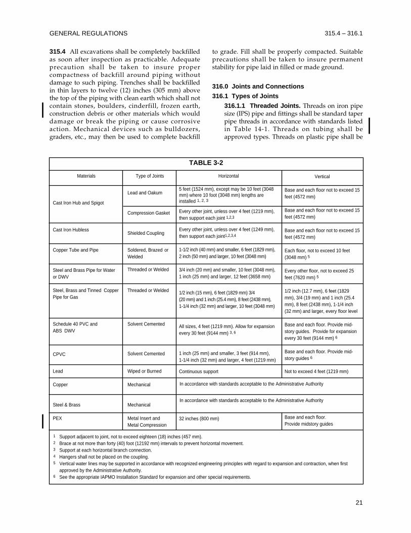
GENERAL REGULATIONS
21
315.4 All excavations shall be completely backfilledas soon after inspection as practicable. Adequateprecaution shall be taken to insure propercompactness of backfill around piping withoutdamage to such piping. Trenches shall be backfilledin thin layers to twelve (12) inches (305 mm) abovethe top of the piping with clean earth which shall notcontain stones, boulders, cinderfill, frozen earth,construction debris or other materials which woulddamage or break the piping or cause corrosiveaction. Mechanical devices such as bulldozers,graders, etc., may then be used to complete backfill
to grade. Fill shall be properly compacted. Suitableprecautions shall be taken to insure permanentstability for pipe laid in filled or made ground.
316.0 Joints and Connections
316.1 Types of Joints
316.1.1 Threaded Joints. Threads on iron pipesize (IPS) pipe and fittings shall be standard taperpipe threads in accordance with standards listedin Table 14-1. Threads on tubing shall beapproved types. Threads on plastic pipe shall be
315.4 – 316.1
TABLE 3-2
Materials
Cast Iron Hub and Spigot
Cast Iron Hubless
Copper Tube and Pipe
Steel and Brass Pipe for Wateror DWV
Steel, Brass and Tinned CopperPipe for Gas
Schedule 40 PVC and ABS DWV
CPVC
Lead
Copper
Steel & Brass
PEX
Type of Joints
Lead and Oakum
Compression Gasket
Shielded Coupling
Soldered, Brazed orWelded
Threaded or Welded
Threaded or Welded
Solvent Cemented
Solvent Cemented
Wiped or Burned
Mechanical
Mechanical
Metal Insert andMetal Compression
Horizontal
5 feet (1524 mm), except may be 10 feet (3048mm) where 10 foot (3048 mm) lengths areinstalled 1, 2, 3
Every other joint, unless over 4 feet (1219 mm),then support each joint 1,2,3
Every other joint, unless over 4 feet (1249 mm),then support each joint1,2,3,4
1-1/2 inch (40 mm) and smaller, 6 feet (1829 mm),2 inch (50 mm) and larger, 10 feet (3048 mm)
3/4 inch (20 mm) and smaller, 10 feet (3048 mm),1 inch (25 mm) and larger, 12 feet (3658 mm)
1/2 inch (15 mm), 6 feet (1829 mm) 3/4 (20 mm) and 1 inch (25.4 mm), 8 feet (2438 mm), 1-1/4 inch (32 mm) and larger, 10 feet (3048 mm)
All sizes, 4 feet (1219 mm). Allow for expansionevery 30 feet (9144 mm) 3, 6
1 inch (25 mm) and smaller, 3 feet (914 mm), 1-1/4 inch (32 mm) and larger, 4 feet (1219 mm)
Continuous support
32 inches (800 mm)
Vertical
Base and each floor not to exceed 15feet (4572 mm)
Base and each floor not to exceed 15feet (4572 mm)
Base and each floor not to exceed 15feet (4572 mm)
Each floor, not to exceed 10 feet(3048 mm) 5
Every other floor, not to exceed 25feet (7620 mm) 5
1/2 inch (12.7 mm), 6 feet (1829mm), 3/4 (19 mm) and 1 inch (25.4mm), 8 feet (2438 mm), 1-1/4 inch(32 mm) and larger, every floor level
Base and each floor. Provide mid-story guides. Provide for expansionevery 30 feet (9144 mm) 6
Base and each floor. Provide mid-story guides 6
Not to exceed 4 feet (1219 mm)
Base and each floor. Provide midstory guides
1 Support adjacent to joint, not to exceed eighteen (18) inches (457 mm).2 Brace at not more than forty (40) foot (12192 mm) intervals to prevent horizontal movement.3 Support at each horizontal branch connection.4 Hangers shall not be placed on the coupling.5 Vertical water lines may be supported in accordance with recognized engineering principles with regard to expansion and contraction, when first
approved by the Administrative Authority.6 See the appropriate IAPMO Installation Standard for expansion and other special requirements.
In accordance with standards acceptable to the Administrative Authority
In accordance with standards acceptable to the Administrative Authority
factory cut or molded. Threaded plastic pipe shallbe Schedule 80 minimum wall thickness. Tubingthreads shall conform to fine tubing threadstandards. When a pipe joint material is used, itshall be applied only on male threads and suchmaterials shall be approved types, insoluble inwater and nontoxic. Cleanout plugs and capsshall be lubricated with water-insoluble, non-hardening material or tape. Only listed threadtape or thread lubricants and sealants specificallyintended for use with plastics shall be used onplastic threads. Conventional pipe threadcompounds, putty, linseed oil base products andunknown lubricants and sealants shall not beused on plastic threads.
316.1.2 Wiped Joints. Joints in lead pipe orfittings or between lead pipe or fittings andbrass or copper pipe, ferrules, solder nipples ortraps, shall be full-wiped joints. Wiped jointsshall have an exposed surface on each side of ajoint not less than three-fourths (3/4) inch (19.1mm) and at least as thick as the material beingjoined. Wall or floor flange lead-wiped jointsshall be made by using a lead ring or flangeplaced behind the joint at wall or floor. Jointsbetween lead pipe and cast iron, steel orwrought iron shall be made by means of acaulking ferrule or soldering nipple.
316.1.3 Soldered Joints. Joints in coppertubing shall be made by the appropriate use ofapproved copper or copper alloy fittings.Surfaces to be joined by soldering shall becleaned bright by manual or mechanical means.The joints shall be properly fluxed with anapproved type flux, and made up withapproved solder. All solder and fluxes shall bemanufactured to approved standards. Soldersand fluxes with a lead content which exceedstwo-tenths (0.20) of one (1) percent shall beprohibited in piping systems used to conveypotable water.
316.1.4 Flared Joints. Flared joints for softcopper tubing shall be made with fittingsmeeting approved standards. The tubing shallbe reamed to the full inside diameter, resized toround and expanded with a proper flaring tool.
316.1.5 Flexible Compression Factory-Fabricated Joints. When pipe is joined bymeans of flexible compression joints, such jointsshall conform to approved standards and shallnot be considered as slip joints.
316.1.6 Solvent Cement Plastic Pipe Joints.Plastic pipe and fittings designed to be joined bysolvent cementing shall comply withappropriate IAPMO Installation Standards.
ABS pipe and fittings shall be cleaned andthen joined with listed solvent cement(s).
CPVC and PVC pipe and fittings shall becleaned and joined with listed primer(s) andsolvent cement(s).
316.1.7 Brazing and Welding. Brazing andwelding shall conform to the applicablestandard(s) in Table 14-1. All brazing on medicalgas systems shall be performed by certifiedinstallers meeting the requirements ofANSI/ASME Boiler and Pressure Vessel Code,Section IX, Welding and Brazing Qualificationsor AWS B2.2, Standard for Brazing Procedureand Performance Qualifications.
316.1.8 Pressure-Lock Type Connection. Amechanical connection which depends on aninternal retention device to prevent pipe ortubing separation. Connection is made byinserting the pipe or tubing into the fitting to aprescribed depth.
316.2 Special Joints
316.2.1 Copper Tubing to Screw Pipe Joints.Joints from copper tubing to threaded pipe shallbe made by the use of brass adapter fittings. Thejoint between the copper tubing and the fittingshall be properly soldered, and the connectionbetween the threaded pipe and the fitting shallbe made with a standard pipe size screw joint.Solder shall conform to the requirements ofSection 316.1.3.
316.2.2 Unions. Approved unions may be usedin drainage work when accessibly located in thetrap seal or between a fixture and its trap; in thevent system, except underground or in wet vents;at any point in the water supply system and ingas piping as permitted by Section 1211.12.
316.2.3 Plastic Pipe to Other Materials. Whenconnecting plastic pipe to other types of piping,only approved types of fittings and adaptersdesigned for the specific transition intendedshall be used.
316.3 Flanged Fixture Connections
316.3.1 Fixture connections between drainagepipes and water closets and floor outlet servicesinks and urinals shall be made by means ofapproved brass, hard lead, ABS, PVC, or ironflanges caulked, soldered, solvent cemented, orscrewed to the drainage pipe. The connectionshall be bolted with an approved gasket, washer,or setting compound between the fixture and theconnection. The bottom of the flange shall be seton an approved firm base.
UNIFORM PLUMBING CODE
22
316.1 – 316.3
316.3.2 Closet bends or stubs shall be cut off so asto present a smooth surface even with the top ofthe closet ring before rough inspection is called.
316.3.3 Wall-mounted water closet fixturesshall be securely bolted to an approved carrierfitting. The connecting piping between thecarrier fitting and the fixture shall be anapproved material and designed toaccommodate an adequately sized gasket.Gasket material shall be neoprene, felt, or similarapproved types.
316.4 Prohibited Joints and Connections
316.4.1 Drainage System. Any fitting orconnection which has an enlargement, chamberor recess with a ledge, shoulder or reduction ofpipe area, that offers an obstruction to flowthrough the drain shall be prohibited.
316.4.2 No fitting or connection that offersabnormal obstruction to flow shall be used. Theenlargement of a three (3) inch (80 mm) closetbend or stub to four (4) inches (100 mm) shallnot be considered an obstruction.
317.0 Increasers and Reducers
Where different sizes of pipes or pipes and fittingsare to be connected, the proper size increasers orreducers or reducing fittings shall be used betweenthe two sizes. Brass or cast iron body cleanouts shallnot be used as a reducer or adapter from cast irondrainage pipe to iron pipe size (IPS) pipe.
318.0 Food Handling Establishments
Food or drink shall not be stored, prepared ordisplayed beneath soil or drain pipes, unless thoseareas are protected against leakage or condensationfrom such pipes reaching the food or drink asdescribed below. Where building design requiresthat soil or drain pipes be located over such areas,the installation shall be made with the least possiblenumber of joints and shall be installed so as toconnect to the nearest adequately sized vertical stackwith the provisions as follows:
318.1 All openings through floors over suchareas shall be sealed watertight to the floorconstruction.
318.2 Floor and shower drains installed abovesuch areas shall be equipped with integralseepage pans.
318.3 All other soil or drain pipes shall be of anapproved material as listed in Table 14-1 andSection 701.0. All materials shall conform toestablished standards. Cleanouts shall beextended through the floor construction above.
318.4 Soil and drain pipes located above suchareas shall be subjected to a standing water testof not less than twenty-five (25) feet (7620 mm).
318.5 Piping subject to operation attemperatures that will form condensation on theexterior of the pipe shall be thermally insulated.
318.6 Where pipes are installed in ceilings abovesuch areas, the ceiling shall be of the removabletype, or shall be provided with access panels inorder to form a ready access for inspection ofpiping.
318.7 In lieu of the above, any other methodmay be approved by the AdministrativeAuthority.
319.0 Test Gauges. Tests required by this Code,which are performed utilizing dial gauges, shall belimited to gauges having the following pressuregraduations or incrementations.
319.1 Required pressure tests of ten (10) psi (69kPa) or less shall be performed with gauges of1/10 pound (0.7 kPa) incrementation or less.
319.2 Required pressure tests exceeding ten (10)pounds (69 kPa) but less than one hundred (100)psi (689 kPa) shall be performed with gauges ofone (1) psi (6.9 kPa) incrementation or less.
319.3 Required pressure tests exceeding onehundred (100) psi (689 kPa) shall be performedwith gauges incremented for two (2) percent orless of the required test pressure.
319.4 Test gauges shall have a pressure rangenot greater than twice the test pressure applied.
GENERAL REGULATIONS
23
316.3 – 319.4

UNIFORM PLUMBING CODE
24
401.0 Materials – General Requirements
401.1 Quality of Fixtures. Plumbing fixtures shallbe constructed of dense, durable, non-absorbentmaterials and shall have smooth, impervioussurfaces, free from unnecessary concealed foulingsurfaces. Except as permitted elsewhere in this Code,all fixtures shall conform in quality and design tonationally recognized applicable standards or toother approved standards acceptable to theAdministrative Authority. A list of acceptedplumbing fixture standards is included in Table 14-1.
401.2 Lead. See Table 14-1. Sheet lead shall be notless than the following:
For safe pans – not less than four (4) pounds persquare foot (19.5 kg/m2) or 1/16 inch (1.6 mm) thick.
402.0 Water-Conserving Fixtures and Fittings
402.1 The maximum discharge flow rates forplumbing fixture fittings shall be in accordance withapplicable standards referenced in Chapter 3 andlisted in Table 14-1.
402.2 Flush volumes for low consumption andwater saver water closets and urinals shall be inaccordance with applicable standards referenced inChapter 3 and listed in Table 14-1.
402.3 Water Closets. Water closets, either flushtank, flushometer tank, or flushometer valveoperated, shall have an average consumption of notmore than 1.6 gallons (6.1 liters) of water per flush.
402.4 Urinals. Urinals shall have an average waterconsumption of not more than 1.0 gallon (3.8 liters)of water per flush.
Exception: If approved by the AdministrativeAuthority, blowout urinals may be installed forpublic use in stadiums, race courses,fairgrounds, and other structures used foroutdoor assembly and for similar uses.
402.5 Non-Metered Faucets. Lavatory faucets shallbe designed and manufactured so that they will notexceed a water flow rate of 2.2 gallons (8.4 liters) perminute.
402.6 Metered Faucets. Self-closing or self-closingmetering faucets shall be installed on lavatoriesintended to serve the transient public, such as thosein, but not limited to, service stations, train stations,airports, restaurants and convention halls. Meteredfaucets shall deliver not more than 0.25 gallons (1.0liter) of water per use.
402.7 Kitchen Faucets. Faucets for kitchen sinksshall be designed and manufactured so that they willnot exceed a water flow rate of 2.2 gallons (8.4 liters)per minute.402.8 Shower Heads. Shower heads shall bedesigned and manufactured so that they will notexceed a water supply flow rate of 2.5 gallons (9.5liters) per minute.
Exception: Emergency safety showers.402.9 Installation. Water-conserving fixtures shall beinstalled in strict accordance with the manufacturers’instructions to maintain their rated performance.
403.0 Materials – Alternates
Special use fixtures may be made of soapstone,chemical stoneware, or may be lined with lead,copper base alloy, nickel-copper alloy, corrosion-resisting steel, or other materials especially suited forthe use for which the fixture is intended.403.1 Zinc Alloy Components. Zinc alloycomponents shall meet the applicable nationallyrecognized standards and shall be used inaccordance with their listing.
404.0 Overflows
When any fixture is provided with an overflow, thewaste shall be so arranged that the standing water inthe fixture cannot rise in the overflow when thestopper is closed or remain in the overflow when thefixture is empty. The overflow pipe from a fixtureshall be connected on the house or inlet side of thefixture trap, except that overflow on flush tanks maydischarge into the water closets or urinals served bythem, but it shall be unlawful to connect suchoverflows with any other part of the drainage system.
405.0 Strainers and Connections
405.1 Strainers. All plumbing fixtures, other thanwater closets and urinals, shall be equipped withapproved strainers having an approved waterwayarea. Strainers serving shower drains shall have awaterway equivalent to the area of the tailpiece.405.2 Connections. Fixtures having concealed slipjoint connections shall be provided with an accesspanel or utility space at least twelve (12) inches (305mm) in its least dimension and so arranged withoutobstructions as to make such connections accessiblefor inspection and repair.
25
CHAPTER 4
PLUMBING FIXTURES AND FIXTURE FITTINGS
405.3 Continuous wastes and fixture tailpieces shallbe constructed from the materials specified inSection 701.0 for drainage piping, provided,however, that such connections where exposed oraccessible may be of seamless drawn brass not lessthan No. 20 B&S Gauge (0.032 inches) (0.8 mm). Eachsuch tailpiece, continuous waste, or waste andoverflow shall not be less than one and one-half (1-1/2) inches (40 mm) O.D. for sinks, dishwashers,laundry tubs, bathtubs, urinals and similar fixtures,and not less than one and one-quarter (1-1/4) inches(32 mm) for lavatories, drinking fountains, andsimilar small fixtures.
405.4 Approved wye or other directional typebranch fittings shall be installed in all continuouswastes connecting or receiving the discharge fromfood waste disposal units, dishwashers,clotheswashers, or other force discharge fixtures orappliances. No dishwasher drain shall be connectedto a sink tailpiece, continuous waste or trap on thedischarge side of a food waste disposal unit.
406.0 Prohibited Fixtures
406.1 Water closets having an invisible seal or anunventilated space or having walls which are notthoroughly washed at each discharge shall beprohibited. Any water closet which might permitsiphonage of the contents of the bowl back into thetank shall be prohibited. Drinking fountains shall notbe installed in public toilet rooms.
406.2 Prohibited Urinals. Floor-type and wall-hung-type trough urinals shall be prohibited. Urinalswhich have an invisible seal or which have anunventilated space or wall which is not thoroughlywashed at each discharge shall be prohibited.
406.3 Fixed wooden, concrete, cement, or tile washtrays or sinks for domestic use shall not be installedin any building designed or used for humanhabitation. No sheet metal lined wooden bathtubshall be installed or reconnected. No dry or chemicalcloset (toilet) shall be installed in any building usedfor human habitation, unless first approved by theHealth Officer.
406.4 Concealed Fouling Surfaces. Fixtures shallbe so designed that they are free from concealedfouling surfaces.
407.0 Special Fixtures and Specialties
407.1 Water Connections. Baptisteries, ornamentaland lily ponds, aquaria, ornamental fountain basins,and similar constructions when provided with watersupplies shall be protected from back-siphonage.
407.2 Restaurant kitchen and other special use sinks
may be made of approved type bonderized andgalvanized sheet steel of not less than No. 16 U.S.Gauge (0.0625 inches) (1.6 mm). All sheet metalplumbing fixtures shall be adequately designed,constructed, and braced in an approved manner tosatisfactorily accomplish their intended purpose.
407.3 Approved. Specialties requiring water andwaste connections shall be submitted for approval ofthe Administrative Authority.
408.0 Installation
408.1 Cleaning. Plumbing fixtures shall be installedin a manner to afford easy access for repairs andcleaning. Where practical, all pipes from fixturesshall be run to the nearest wall.
408.2 Joints. Where a fixture comes in contact withthe wall or floor, the joint between the fixture andthe wall or floor shall be made watertight.
408.3 Securing Fixtures. Floor outlet or floormounted fixtures shall be rigidly secured to thedrainage connection and to the floor when sodesigned, by screws or bolts of copper, brass, orother equally corrosion resistant material.
408.4 Wall-Hung Fixtures. Wall-hung fixtures shallbe rigidly supported by metal supporting membersso that no strain is transmitted to the connections.Flush tanks and similar appurtenances shall besecured by approved non-corrosive screws or bolts.
408.5 Securing Floor-Mounted, Back-OutletWater Closet Bowls. Floor-mounted, back-outletwater closet bowls shall be set level with an angle ofninety (90) degrees (1.58 rad) between the floor andwall at the centerline of the fixture outlet. The floorand wall shall have a flat mounting surface for atleast five (5) inches (127 mm) to the right and left ofthe fixture outlet centerline. The fixture shall besecured to the wall outlet flange or drainageconnection, and to the floor by corrosion-resistantscrews or bolts. The closet flange shall be secured toa firm base.
Where floor-mounted, back-outlet water closetsare used, the soil pipe shall not be less than three (3)inches (80 mm) in diameter. Offset, eccentric, orreducing floor flanges shall not be used.
408.6 Setting. Fixtures shall be set level and inproper alignment with reference to adjacent walls.No water closet or bidet shall be set closer thanfifteen (15) inches (381mm) from its center to anyside wall or obstruction nor closer than thirty (30)inches (762 mm) center to center to any similarfixture. The clear space in front of any water closet orbidet shall not be less than twenty-four (24) inches(610 mm). No urinal shall be set closer than twelve
UNIFORM PLUMBING CODE
26
405.3 – 408.6
(12) inches (305 mm) from its center to any side wallor partition nor closer than twenty-four (24) inches(610 mm) center to center.
408.7 Installations for the Handicapped. Wherefacilities for the handicapped are required inapplicable building regulations, the facilities shall beinstalled in accordance with those regulations.
408.8 Supply Fittings. The supply lines or fittingsfor every plumbing fixture shall be so installed as toprevent backflow as required in Chapter 6.
409.0 Water Closets
409.1 Water closet bowls for public use shall be ofthe elongated type. In nurseries, schools, and othersimilar places where plumbing fixtures are providedfor the use of children under six (6) years of age,water closets shall be of a size and height suitable forchildren’s use. All water closets shall be equippedwith seats as required below.
409.2 Water Closet Seats
409.2.1 Water closet seats shall be of smoothnon-absorbent material.
409.2.2 All water closet seats, except thosewithin dwelling units, shall be of the open fronttype.
409.2.3 Water closet seats shall be properlysized for the water closet bowl type.
409.2.4 Seats for use in public buildings shallconform to the standard listed in Table 14-1.
410.0 Urinals
Every water supply to a urinal shall be protected byan approved type vacuum breaker or otherapproved backflow prevention device as describedin Section 603.3.
411.0 Flushing Devices for Water Closets andUrinals
411.1 Flushing Devices Required. Each watercloset, urinal, clinic sink, or other plumbing fixturewhich depends on trap siphonage to discharge itswaste contents shall be provided with a flushometervalve, flushometer tank or flush tank designed andinstalled so as to supply water in sufficient quantityand rate of flow to flush the contents of the fixture towhich it is connected, to cleanse the fixture, and torefill the fixture trap, without excessive water use.Flushing devices shall meet anti-siphonrequirements required in Chapter 6.
411.2 Automatic Flushing Tanks. Tanks flushingmore than one (1) urinal shall be automatic inoperation and of sufficient capacity to provide the
necessary volume to flush and properly cleanse allurinals simultaneously. Automatically controlledflushometer valves may be substituted for flushtanks.
411.3 Flushometer Valves. No manuallycontrolled flushometer valve shall be used to flushmore than one (1) urinal and each such urinalflushometer valve shall be an approved, self-closingtype discharging a predetermined quantity of water.Flushometers shall be installed so that they will beaccessible for repair. Flushometer valves shall not beused where the water pressure is insufficient toproperly operate them. When the valve is operated,it shall complete the cycle of operation automatically,opening fully and closing positively under the linewater pressure. Each flushometer shall be providedwith a means for regulating the flow through it.
411.4 Water Supply for Flush Tanks. An adequatequantity of water shall be provided to flush and cleanthe fixture served. The water supply for flushingtanks and flushometer tanks equipped for manualflushing shall be controlled by a float valve or otherautomatic device designed to refill the tank after eachdischarge and to completely shut off the water flowto the tank when the tank is filled to operationalcapacity. Provision shall be made to automaticallysupply water to the fixture so as to refill the trap sealafter each flushing. The water supply to flush tanksequipped for automatic flushing shall be controlledby a suitable timing device.
411.5 Flush Valves in Flush Tanks. Flush valveseats in tanks for flushing water closets shall be at leastone (1) inch (25.4 mm) above the flood level rim of thebowl connected thereto, except in approved watercloset and flush tank combinations designed so thatwhen the tank is flushed and the fixture is clogged orpartially clogged, the flush valve closes tightly so thatwater does not spill continuously over the rim of thebowl or backflow from the bowl to the tank.
411.6 Overflows in Flush Tanks. Flush tanks shallbe provided with overflows discharging into thewater closet or urinal connected thereto and shall beof sufficient size to prevent tank flooding at themaximum rate at which the tank is supplied withwater under normal operating conditions.
412.0 Floor Drains and Shower Stalls
412.1 Floor drains shall be considered plumbingfixtures and each such drain shall be provided withan approved type strainer having a waterwayequivalent to the area of the tailpiece. Floor drains,floor receptors, and shower drains shall be of anapproved type, suitably flanged to provide awatertight joint in the floor.
PLUMBING FIXTURES AND FIXTURE FITTINGS 408.6 – 412.1
27
UNIFORM PLUMBING CODE
28
412.2 Location of Floor Drains. Floor drains shallbe installed in the following areas:
412.2.1 Toilet rooms containing two (2) or morewater closets or a combination of one (1) watercloset and one (1) urinal, except in a dwellingunit. The floor shall slope toward the floordrains.
412.2.2 Commercial kitchens.
412.2.3 Laundry rooms in commercialbuildings and common laundry facilities inmulti-family dwelling buildings.
412.3 Food Storage Areas. If drains are providedin storerooms, walk-in freezers, walk-in coolers,refrigerated equipment, or other locations wherefood is stored, such drains shall have indirect wastepiping. Separate waste pipes shall be run from eachfood storage area, each with an indirect connectionto the building sanitary drainage system. Traps shallbe provided if required under Section 801.2.2 of thisCode and shall be vented.
Indirect drains may be located in freezers orother spaces where freezing temperatures aremaintained, provided that traps, when provided, arelocated where the seal will not freeze. Otherwise, thefloor of the freezer shall be sloped to a floor drainlocated outside of the storage compartment.
412.4 Floor Slope. Floors shall be sloped to floordrains where drainage occurs on a regular orfrequent basis, or as otherwise required by theAdministrative Authority.
412.5 Shower receptors are plumbing fixtures andshall conform to the general requirements thereforcontained in Section 401.0. Each such showerreceptor shall be constructed of vitrified china orearthenware, ceramic tile, porcelain enameled metalor of such other material as may be acceptable to theAdministrative Authority. No shower receptor shallbe installed unless it conforms to acceptablestandards as referenced in Chapter 3 and listed inTable 14-1 or until a specification or a prototype orboth of such receptor has first been submitted to andapproval obtained from the AdministrativeAuthority.
412.6 Each shower receptor shall be an approvedtype and be so constructed as to have a finisheddam, curb, or threshold which is at least one (1) inch(25.4 mm) lower than the sides and back of suchreceptor. In no case shall any dam or threshold beless than two (2) inches (51 mm) or more than nine(9) inches (229 mm) in depth when measured fromthe top of the dam or threshold to the top of thedrain. Each such receptor shall be provided with anintegral nailing flange to be located where the
receptor meets the vertical surface of the finishedinterior of the shower compartment. The flange shallbe watertight and extend vertically a minimum ofone (1) inch (25.4 mm) above the top of the sides ofthe receptor. The finished floor of the receptor shallslope uniformly from the sides toward the drain notless than one-quarter (1/4) inch per foot (20.9mm/m), nor more than one-half (1/2) inch per foot(41.8 mm/m). Thresholds shall be of sufficient widthto accommodate a minimum twenty-two (22) inch(559 mm) door. Shower doors shall open so as tomaintain a minimum twenty-two (22) inch (559 mm)unobstructed opening for egress.
Exception: Showers which are designed tocomply with the accessibility standards listed inTable 14-1.
412.7 All shower compartments, regardless ofshape, shall have a minimum finished interior of onethousand twenty-four (1024) square inches (0.66 m2)and shall also be capable of encompassing a thirty(30) inch (750 mm) circle. The minimum requiredarea and dimensions shall be measured at a heightequal to the top of the threshold and at a pointtangent to its centerline. The minimum area anddimensions shall be maintained to a point seventy(70) inches (1778 mm) above the shower drain outletwith no protrusions other than the fixture valve orvalves, shower head, soap dishes, shelves and safetygrab bars or rails. Fold-down seats in accessibleshower stalls shall be permitted to protrude into thethirty (30) inch (750 mm) circle.
Exception: Showers which are designed tocomply with the accessibility standards listed inTable 14-1.
412.8 When the construction of on-site built-upshower receptors is permitted by the AdministrativeAuthority, one of the following means shall beemployed:
(1) Shower receptors built directly on theground:
Shower receptors built directly on the groundshall be watertight and shall be constructed fromapproved type dense, non-absorbent and non-corrosive materials. Each such receptor shall beadequately reinforced, shall be provided with anapproved flanged floor drain designed to makea watertight joint in the floor, and shall havesmooth, impervious, and durable surfaces.
(2) Shower receptors built above ground:
When shower receptors are built above ground thesub-floor and rough side of walls to a height of notless than three (3) inches (76 mm) above the top ofthe finished dam or threshold shall be first lined
412.2 – 412.8
with sheet plastic*, lead* or copper* or shall belined with other durable and watertight materials.
All lining materials shall be pitched one-quarter(1/4) inch per foot (20.9 mm/m) to weep holes in thesubdrain of a smooth and solidly formed sub-base.All such lining materials shall extend upward on therough jambs of the shower opening to a point no less
than three (3) inches (76 mm) above the top of thefinished dam or threshold and shall extend outwardover the top of the rough threshold and be turnedover and fastened on the outside face of both therough threshold and the jambs.
Non-metallic shower sub-pans or linings may bebuilt-up on the job site of not less than three (3)layers of standard grade fifteen (15) pound (6.8 kg)asphalt impregnated roofing felt. The bottom layershall be fitted to the formed sub-base and eachsucceeding layer thoroughly hot mopped to thatbelow. All corners shall be carefully fitted and shallbe made strong and watertight by folding or lapping,and each corner shall be reinforced with suitablewebbing hot-mopped in place. All folds, laps, andreinforcing webbing shall extend at least four (4)inches (102 mm) in all directions from the corner andall webbing shall be of approved type and mesh,producing a tensile strength of not less than fifty (50)psi (344.5 kPa) in either direction. Non-metallicshower sub-pans or linings may also consist of multi-layers of other approved equivalent materialssuitably reinforced and carefully fitted in place onthe job site as elsewhere required in this section.
Linings shall be properly recessed and fastenedto approved backing so as not to occupy the spacerequired for the wall covering and shall not be nailedor perforated at any point which may be less thanone (1) inch (25.4 mm) above the finished dam orthreshold. An approved type sub-drain shall beinstalled with every shower sub-pan or lining. Eachsuch sub-drain shall be of the type that sets flushwith the sub-base and shall be equipped with aclamping ring or other device to make a tightconnection between the lining and the drain. Thesub-drain shall have weep holes into the waste line.The weep holes located in the subdrain clampingring shall be protected from clogging.
All shower lining materials shall conform toapproved standards acceptable to the AdministrativeAuthority.
412.8.1 Tests for Shower Receptors. Showerreceptors shall be tested for watertightness byfilling with water to the level of the roughthreshold. The test plug shall be so placed thatboth upper and under sides of the sub-pan shallbe subjected to the test at the point where it isclamped to the drain.
412.9 Floors of public shower rooms shall have anon-skid surface and shall be drained in such amanner that waste water from one bather will notpass over areas occupied by other bathers. Gutters inpublic or gang shower rooms shall have roundedcorners for easy cleaning and shall be sloped not lessthan two (2) percent toward drains. Drains in guttersshall be spaced not more than eight (8) feet (2438mm) from side walls nor more than sixteen (16) feet(4879 mm) apart.412.10 DELETED
412.11 Location of Valves and Heads. Controlvalves and shower heads shall be located on thesidewall of shower compartments or be otherwisearranged so that the showerhead does not dischargedirectly at the entrance to the compartment and thebather can adjust the valves prior to stepping intothe shower spray.412.12 Water Supply Riser. Every water supplyriser from the shower valve to the shower headoutlet, whether exposed or not, shall be securelyattached to the structure.
413.0 Minimum Number of Required Fixtures
413.1 Fixture Count. Plumbing fixtures shall beprovided for the type of building occupancy and inthe minimum number shown in Table 4-1.413.2 Access to Fixtures
413.2.1 In multi-story buildings, accessibility tothe required fixtures shall not exceed one (1)vertical story.413.2.2 Fixtures accessible only to privateoffices shall not be counted to determinecompliance with this section.
413.3 Separate Facilities
Separate toilet facilities shall be provided for each sex.Exceptions:
(1) Residential installations.(2) In occupancies serving ten (10) or fewerpeople, one (1) toilet facility, designed for use byno more than one (1) person at a time, shall bepermitted for use by both sexes.
PLUMBING FIXTURES AND FIXTURE FITTINGS 412.8 – 413.3
29
___________
*Lead and copper sub-pans or linings shall be insulated fromall conducting substances other than their connecting drain byfifteen (15) pound (6.8 kg) asphalt felt or its equivalent and nolead pan or liner shall be constructed of material weighing lessthan four (4) pounds per square foot (19.5 kg/m2). Copperpans or liners shall be at least No. 24 B & S Gauge (0.02inches) (0.5 mm). Joints in lead pans or liners shall be burned.Joints in copper pans or liners shall be soldered or brazed.Plastic pans shall not be coated with asphalt based materials.
(3) In business and mercantile occupancies witha total floor area of fifteen hundred (1500) squarefeet (139.5 m2) or less, one (1) toilet facility,designed for use by no more than one (1) personat a time, shall satisfy the requirements forserving customers and employees of both sexes.
413.4 Fixture Requirements for SpecialOccupancies
413.4.1 Additional fixtures may be requiredwhen unusual environmental conditions orspecial activities are encountered.413.4.2 In food preparation areas, fixturerequirements may be dictated by health codes.413.4.3 Types of occupancy not shown in Table4-1 shall be considered individually by theAdministrative Authority.
413.5 Facilities in Mercantile and BusinessOccupancies Serving Customers
413.5.1 Requirements for customers andemployees shall be permitted to be met with asingle set of restrooms accessible to both groups.The required number of fixtures shall be thegreater of the required number for employees orthe required number for customers.413.5.2 Fixtures for customer use shall bepermitted to be met by providing a centrallylocated facility accessible to several stores. Themaximum distance from entry to any store tothis facility shall not exceed five hundred (500)feet (152.4 m).413.5.3 In stores with a floor area of onehundred fifty (150) square feet (13.9 m2) or less,the requirement to provide facilities foremployees shall be permitted to be met byproviding a centrally located facility accessibleto several stores. The maximum distance fromentry to any store to this facility shall not exceedthree hundred (300) feet (91.4 m).
413.6 Food Service Establishments. Food serviceestablishments with an occupant load of onehundred (100) or more shall be provided withseparate facilities for employees and customers.Customer and employee facilities may be combinedfor occupant loads less than one hundred (100).413.7 Toilet Facilities for Workers
Suitable toilet facilities shall be provided andmaintained in a sanitary condition for the use ofworkers during construction.
414.0 Fixtures and Fixture Fittings for Personswith Disabilities
Plumbing fixtures and fixture fittings for personswith disabilities shall conform to the appropriatestandards referenced in Table 14-1 of this Code.
415.0 Whirlpool Bathtubs
Unless otherwise listed, all whirlpool bathtubs shallcomply with the following requirements:415.1 A removable panel of sufficient dimensionshall be provided to access the pump.415.2 The circulation pump shall be located abovethe crown weir of the trap.415.3 The pump and the circulation piping shall beself-draining to minimize water retention inaccordance with standards referenced in Table 14-1.415.4 Suction fittings on whirlpool bathtubs shallcomply with the listed standards.
416.0 Installation of Fixture Fittings
Faucets and diverters shall be installed and adjustedso that the flow of hot water from the fittingscorresponds to the left hand side of the fitting duringfixture operation.
Exception: In single handle mixing valves, theflow of hot water shall correspond to themarkings on the fitting.
417.0 Bidets
417.1 Materials. Bidets shall conform to thestandards listed in Table 14-1.417.2 Backflow Protection. The water supply tothe bidet shall be protected according to Chapter 6,which allows for an airgap or vacuum breaker.
418.0 DELETED
419.0 Future Fixtures
When provision is made for the future installation offixtures, those provided for shall be considered indetermining the required sizes of drain pipes.Construction for future installations shall beterminated with a plugged fitting or fittings. Wherethe plugged fitting is at the point where the trap of afixture may be installed, the plumbing system forsuch fixture shall be complete and conform with allplumbing requirements of this Code.
420.0 Shower and Tub/Shower CombinationControl Valves
Showers and tub-shower combinations in allbuildings shall be provided with individual controlvalves of the pressure balance or the thermostaticmixing valve type. Gang showers, when suppliedwith a single temperature controlled water supplypipe, may be controlled by a master thermostaticmixing valve in lieu of individually controlled
UNIFORM PLUMBING CODE
30
413.3 – 420.0
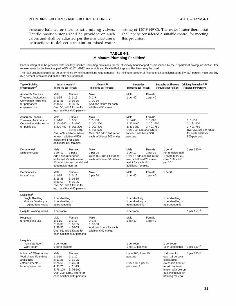
PLUMBING FIXTURES AND FIXTURE FITTINGS 420.0 – Table 4-1
31
pressure balance or thermostatic mixing valves.Handle position stops shall be provided on suchvalves and shall be adjusted per the manufacturer’sinstructions to deliver a maximum mixed water
setting of 120°F (49°C). The water heater thermostatshall not be considered a suitable control for meetingthis provision.
TABLE 4-1Minimum Plumbing Facilities1
Each building shall be provided with sanitary facilities, including provisions for the physically handicapped as prescribed by the Department having jurisdiction. Forrequirements for the handicapped, ANSI A117.1-1992, Accessible and Usable Buildings and Facilities, may be used.
The total occupant load shall be determined by minimum exiting requirements. The minimum number of fixtures shall be calculated at fifty (50) percent male and fifty(50) percent female based on the total occupant load.
Type of Building Water Closets14 Urinals5, 10 Lavatories Bathtubs or Showers Drinking Fountains3, 13
or Occupancy2 (Fixtures per Person) (Fixtures per Person) (Fixtures per Person) (Fixtures per Person) (Fixtures per Person)
Assembly Places – Male Female Male Male FemaleTheatres, Auditoriums, 1: 1-15 1: 1-15 0: 1-9 1 per 40 1 per 40Convention Halls, etc. – 2: 16-35 3: 16-35 1: 10-50for permanent 3: 36-55 4: 36-55 Add one fixture for eachemployee use Over 55, add 1 fixture for additional 50 males.
each additional 40 persons.
Assembly Places – Male Female Male Male FemaleTheatres, Auditoriums, 1: 1-100 3: 1-50 1: 1-100 1: 1-200 1: 1-200 1: 1-150Convention Halls, etc. – 2: 101-200 4: 51-100 2: 101-200 2: 201-400 2: 201-400 2: 151-400for public use 3: 201-400 8: 101-200 3: 201-400 3: 401-750 3: 401-750 3: 401-750
11: 201-400 4: 401-600 Over 750, add one fixture Over 750, add one fixtureOver 400, add one fixture Over 600 add 1 fixture for for each additional 500 for each additional for each additional 500 each additional 300 males. persons. 500 persons.males and 1 for each additional 125 females.
Dormitories9 Male Female Male Male Female 1 per 8 1 per 15012
School or Labor 1 per 10 1 per 8 1 per 25 1 per 12 1 per 12 For females, addAdd 1 fixture for each Over 150, add 1 fixture for Over 12 add one fixture for 1 bathtub per 30.additional 25 males (over each additional 50 males. each additional 20 males Over 150, add 110) and 1 for each additional and 1 for each 15 per 20.20 females (over 8). additional females.
Dormitories – Male Female Male Male Female 1 per 8for staff use 1: 1-15 1: 1-15 1 per 50 1 per 40 1 per 40
2: 16-35 3: 16-353: 36-55 4: 36-55Over 55, add 1 fixture foreach additional 40 persons.
Dwellings4
Single Dwelling 1 per dwelling 1 per dwelling 1 per dwellingMultiple Dwelling or 1 per dwelling or 1 per dwelling or 1 per dwelling or
Apartment House apartment unit apartment unit apartment unit
Hospital Waiting rooms 1 per room 1 per room 1 per 15012
Hospitals – Male Female Male Male Femalefor employee use 1: 1-15 1: 1-15 0: 1-9 1 per 40 1 per 40
2: 16-35 3: 16-35 1: 10-503: 36-55 4: 36-55 Add one fixture for eachOver 55, add 1 fixture for additional 50 males.each additional 40 persons.
HospitalsIndividual Room 1 per room 1 per room 1 per roomWard Room 1 per 8 patients 1 per 10 patients 1per 20 patients 1 per 15012
Industrial6 Warehouses Male Female Up to 100, 1 per 10 1 shower for 1 per 15012
Workshops, Foundries 1: 1-10 1: 1-10 persons each 15 personsand similar 2: 11-25 2: 11-25 exposed toestablishments – 3: 26-50 3: 26-50 Over 100, 1 per 15 excessive heat orfor employee use 4: 51-75 4: 51-75 persons7, 8 to skin contam-
5: 76-100 5: 76-100 ination with poison-Over 100, add 1 fixture for ous, infectious, oreach additional 30 persons irritating material
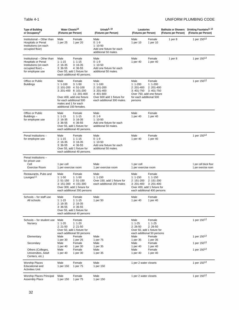
UNIFORM PLUMBING CODE
32
Table 4-1
Type of Building Water Closets14 Urinals5, 10 Lavatories Bathtubs or Showers Drinking Fountains3, 13
or Occupancy2 (Fixtures per Person) (Fixtures per Person) (Fixtures per Person) (Fixtures per Person) (Fixtures per Person)
Institutional – Other than Male Female Male Male Female 1 per 8 1 per 15012
Hospitals or Penal 1 per 25 1 per 20 0: 1-9 1 per 10 1 per 10Institutions (on each 1: 10-50occupied floor) Add one fixture for each
additional 50 males.
Institutional – Other than Male Female Male Male Female 1 per 8 1 per 15012
Hospitals or Penal 1: 1-15 1: 1-15 0: 1-9 1 per 40 1 per 40Institutions (on each 2: 16-35 3: 16-35 1: 10-50occupied floor) – 3: 36-55 4: 36-55 Add one fixture for eachfor employee use Over 55, add 1 fixture for additional 50 males.
each additional 40 persons.
Office or Public Male Female Male Male Female 1 per 15012
Buildings 1: 1-100 3: 1-50 1: 1-100 1: 1-200 1: 1-2002: 101-200 4: 51-100 2: 101-200 2: 201-400 2: 201-4003: 201-400 8: 101-200 3: 201-400 3: 401-750 3: 401-750
11: 201-400 4: 401-600 Over 750, add one fixtureOver 400, add one fixture Over 600 add 1 fixture for for each additional 500for each additional 500 each additional 300 males. personsmales and 1 for each additional 150 females.
Office or Public Male Female Male Male FemaleBuildings – 1: 1-15 1: 1-15 0: 1-9 1 per 40 1 per 40for employee use 2: 16-35 3: 16-35 1: 10-50
3: 36-55 4: 36-55 Add one fixture for eachOver 55, add 1 fixture for additional 50 males.each additional 40 persons.
Penal Institutions – Male Female Male Male Female 1 per 15012
for employee use 1: 1-15 1: 1-15 0: 1-9 1 per 40 1 per 402: 16-35 3: 16-35 1: 10-503: 36-55 4: 36-55 Add one fixture for eachOver 55, add 1 fixture for additional 50 males.each additional 40 persons.
Penal Institutions –for prison use
Cell 1 per cell Male 1 per cell 1 per cell block floorExercise Room 1 per exercise room 1 per exercise room 1 per exercise room 1 per exercise room
Restaurants, Pubs and Male Female Male Male FemaleLounges11 1: 1-50 1: 1-50 1: 1-150 1: 1-150 1: 1-150
2: 51-150 2: 51-150 Over 150, add 1 fixture for 2: 151-200 2: 151-2003: 151-300 4: 151-300 each additional 150 males 3: 201-400 3: 201-400Over 300, add 1 fixture for Over 400, add 1 fixture foreach additional 200 persons each additional 400 persons
Schools – for staff use Male Female Male Male FemaleAll schools 1: 1-15 1: 1-15 1 per 50 1 per 40 1 per 40
2: 16-35 2: 16-353: 36-55 3: 36-55Over 55, add 1 fixture for each additional 40 persons
Schools – for student use Male Female Male Female 1 per 15012
Nursery 1: 1-20 1: 1-20 1: 1-25 1: 1-252: 21-50 2: 21-50 2: 26-50 2: 26-50Over 50, add 1 fixture for Over 50, add 1 fixture foreach additional 50 persons each additional 50 persons
Elementary Male Female Male Male Female 1 per 15012
1 per 30 1 per 25 1 per 75 1 per 35 1 per 35Secondary Male Female Male Male Female 1 per 15012
1 per 40 1 per 30 1 per 35 1 per 40 1 per 40Others (Colleges, Male Female Male Male Female 1 per 15012
Universities, Adult 1 per 40 1 per 30 1 per 35 1 per 40 1 per 40Centers, etc.)
Worship Places Male Female Male 1 per 2 water closets 1 per 15012
Educational and 1 per 150 1 per 75 1 per 150Activities Unit
Worship Places Principal Male Female Male 1 per 2 water closets 1 per 15012
Assembly Place 1 per 150 1 per 75 1 per 150
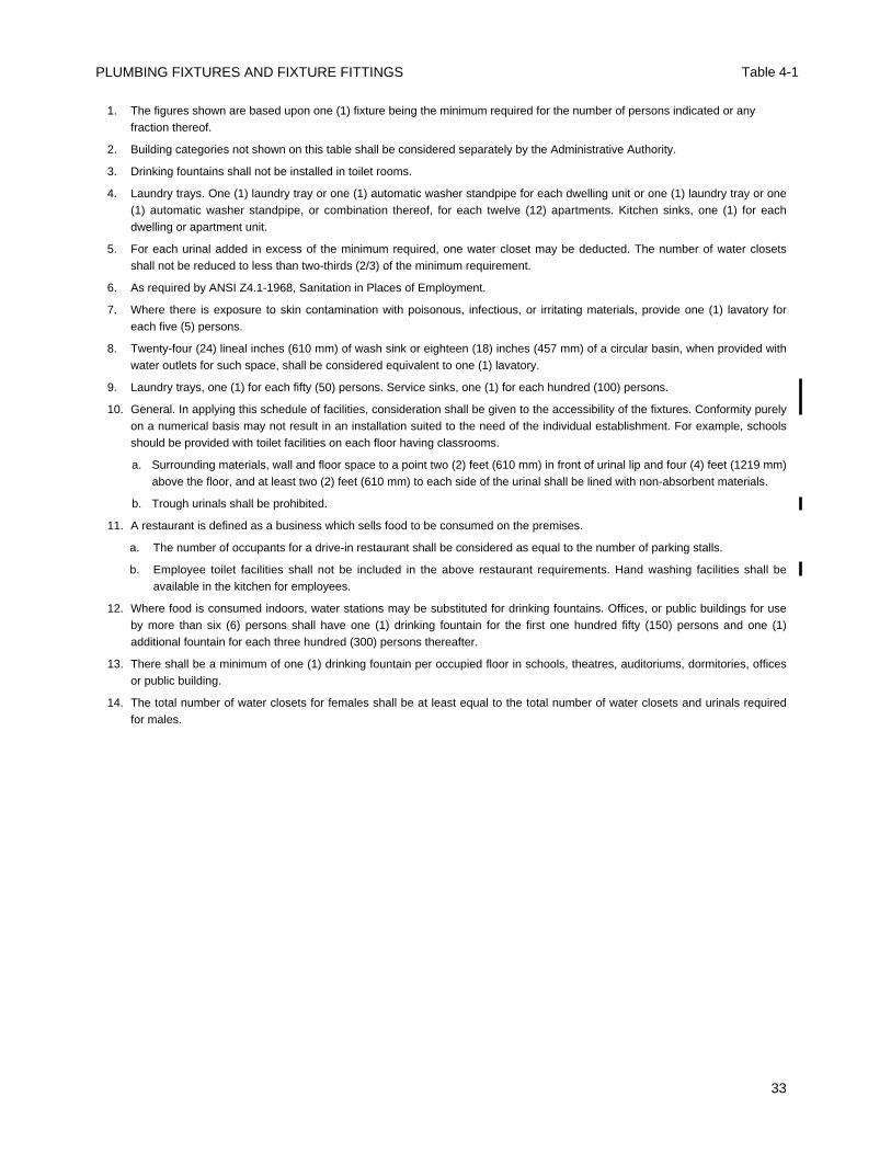
PLUMBING FIXTURES AND FIXTURE FITTINGS Table 4-1
33
1. The figures shown are based upon one (1) fixture being the minimum required for the number of persons indicated or anyfraction thereof.
2. Building categories not shown on this table shall be considered separately by the Administrative Authority.
3. Drinking fountains shall not be installed in toilet rooms.
4. Laundry trays. One (1) laundry tray or one (1) automatic washer standpipe for each dwelling unit or one (1) laundry tray or one(1) automatic washer standpipe, or combination thereof, for each twelve (12) apartments. Kitchen sinks, one (1) for eachdwelling or apartment unit.
5. For each urinal added in excess of the minimum required, one water closet may be deducted. The number of water closetsshall not be reduced to less than two-thirds (2/3) of the minimum requirement.
6. As required by ANSI Z4.1-1968, Sanitation in Places of Employment.
7. Where there is exposure to skin contamination with poisonous, infectious, or irritating materials, provide one (1) lavatory foreach five (5) persons.
8. Twenty-four (24) lineal inches (610 mm) of wash sink or eighteen (18) inches (457 mm) of a circular basin, when provided withwater outlets for such space, shall be considered equivalent to one (1) lavatory.
9. Laundry trays, one (1) for each fifty (50) persons. Service sinks, one (1) for each hundred (100) persons.
10. General. In applying this schedule of facilities, consideration shall be given to the accessibility of the fixtures. Conformity purelyon a numerical basis may not result in an installation suited to the need of the individual establishment. For example, schoolsshould be provided with toilet facilities on each floor having classrooms.
a. Surrounding materials, wall and floor space to a point two (2) feet (610 mm) in front of urinal lip and four (4) feet (1219 mm)above the floor, and at least two (2) feet (610 mm) to each side of the urinal shall be lined with non-absorbent materials.
b. Trough urinals shall be prohibited.
11. A restaurant is defined as a business which sells food to be consumed on the premises.
a. The number of occupants for a drive-in restaurant shall be considered as equal to the number of parking stalls.
b. Employee toilet facilities shall not be included in the above restaurant requirements. Hand washing facilities shall beavailable in the kitchen for employees.
12. Where food is consumed indoors, water stations may be substituted for drinking fountains. Offices, or public buildings for useby more than six (6) persons shall have one (1) drinking fountain for the first one hundred fifty (150) persons and one (1)additional fountain for each three hundred (300) persons thereafter.
13. There shall be a minimum of one (1) drinking fountain per occupied floor in schools, theatres, auditoriums, dormitories, officesor public building.
14. The total number of water closets for females shall be at least equal to the total number of water closets and urinals requiredfor males.

UNIFORM PLUMBING CODE
34
501.0 General
The regulations of this chapter shall govern theconstruction, location, and installation of fuelburning and other water heaters heating potablewater, together with all chimneys, vents, and theirconnectors. The minimum capacity for water heatersshall be in accordance with the first hour rating listedin Table 5-1. All design, construction, andworkmanship shall be in conformity with acceptedengineering practices, manufacturer’s installationinstructions, and applicable standards and shall be ofsuch character as to secure the results sought to beobtained by this Code. No water heater shall behereinafter installed which does not comply in allrespects with the type and model of each size thereofapproved by the Administrative Authority. A list ofaccepted gas equipment standards is included inTable 14-1.
502.0 Definitions
502.1 Chimney – A vertical shaft enclosing one ormore flues for conveying flue gases to the outsideatmosphere.
502.2 Chimney Connector – The pipe whichconnects a fuel-burning appliance to a chimney.
502.3 Combustible Material – Walls, floors,ceilings, shelves, or other parts of a buildingconstructed of wood, wood lath and plaster,composition or paper.
502.4 Dielectric Insulator – A device used as a non-conductor.
502.5 Direct Vent Appliance – Applianceconstructed and installed so that all air forcombustion is derived directly from the outsideatmosphere and all flue gases are discharged directlyto the outside atmosphere.
502.6 Direct Vent Water Heater – A water heaterwhich is constructed and installed so that all air for
combustion is derived directly from the outsideatmosphere and all flue gases are discharged directlyto the outside atmosphere.
502.7 Unusually Tight Construction – Constructionwhere:
(1) Walls and ceiling exposed to the outsideatmosphere have a continuous water vaporretarder with a rating of one perm or less withany openings gasketed or sealed, and
(2) Weatherstripping on openable windowsand doors, and
(3) Caulking or sealants are applied to areassuch as joints around window and door frames,between sole plates and floors, between wall-ceiling joints, between wall panels and atpenetrations for plumbing, electrical and gaslines and at other openings.
502.8 Vent – Listed factory-made vent pipe andvent fittings for conveying products of combustionto the outside atmosphere.
502.9 Vent Collar – The outlet opening of anappliance provided for connection of the ventsystem.
502.10 Vent Connector – That portion of a ventingsystem which connects an appliance to a vent.
502.11 Venting System – The vent or chimney, itsconnectors assembled to form a continuous openpassageway from an appliance to the outsideatmosphere for the purpose of removing products ofcombustion. This definition shall also include theventing assembly which is an integral part of theappliance.
502.12 Venting Systems – Types
(1) Chimneys or vents of masonry, reinforcedconcrete or metal; and factory-built chimneysapproved or listed for products of combustion attemperatures in excess of five hundred fiftydegrees (550°F) (288°C).
35
CHAPTER 5
WATER HEATERS
TABLE 5-11
Notes:1The first hour rating is found on the “Energy Guide” label.2Non-storage and solar water heaters shall be sized to meet the appropriate first hour rating as shown in the table.
Number of Bathrooms 1 to 1.5 2 to 2.5 3 to 3.5Number of Bedrooms 1 2 3 2 3 4 5 3 4 5 6
First Hour Rating2, Gallons 42 54 54 54 67 67 80 67 80 80 80
(2) Type B – Factory-made gas vents listed by anationally recognized testing agency for ventinglisted or approved appliances equipped to burnonly gas.
(3) Type L – A venting system consisting oflisted vent piping and fittings for use with oil-burning appliances listed for use with Type L orwith listed gas appliances.
502.13 Water Heater – An appliance designedprimarily to supply hot water and is equipped withautomatic controls limiting water temperature to amaximum of two hundred ten degrees (210°F) (99°C).
503.0 Permits
It shall be unlawful for any person to install, remove,or replace, or cause to be installed, removed, orreplaced any water heater without first obtaining apermit from the Administrative Authority to do so.
504.0 Inspection
504.1 Inspection of Chimneys or Vents. Thisinspection shall be made after all chimneys, vents, orparts thereof, authorized by the permit, have beeninstalled and before any such vent or part thereof hasbeen covered or concealed.
504.2 Final Water Heater Inspection. Thisinspection shall be made after all work authorized bythe permit has been installed. The AdministrativeAuthority will make such inspection as deemednecessary to be assured that the work has beeninstalled in accordance with the intent of this Code.No equipment or part thereof shall be covered orconcealed until the same has been inspected andapproved by the Administrative Authority.
505.0 Gas-Fired Water Heater ApprovalRequirements
505.1 Gas fired water heaters and gas fired hotwater boilers shall conform to approved recognizedapplicable standards or to other standards acceptableto the Administrative Authority. Each such waterheater or boiler shall bear the label of an approvedtesting agency, certifying and attesting that suchequipment has been tested and inspected and meetsthe requirements of applicable standards.
505.2 Except when reconditioned by themanufacturer or the manufacturer's approved agentin accordance with its original approvalrequirements and reinstalled at its original location,each reconditioned water heater or hot water boilershall be tested for safety and conformity to approvedstandards, and shall bear the label of an approvedtesting agency certifying and attesting that such
equipment has been tested and inspected and meetsthe requirements of applicable standards. Such labelshall also state clearly that the water heater has beenreconditioned, and shall give the name and addressof the reconditioner. Every person applying for apermit to install a used or reconditioned waterheater shall clearly state on the application forpermit that such equipment is used or reconditioned.
505.3 Gas storage-type water heaters and hot waterboilers shall be provided with, in addition to theprimary temperature controls, an over-temperaturesafety protection device constructed, listed, andinstalled in accordance with nationally recognizedapplicable standards for such devices and acombination temperature and pressure relief valve.
506.0 Oil-Burning and Other Water Heaters
506.1 Water heaters deriving heat from fuels ortypes of energy other than gas shall be constructedand installed in accordance with approved standardsin a manner satisfactory to the AdministrativeAuthority. Vents or chimneys for such appliancesshall be approved or listed types and shall be madefor an adequate supply of air for combustion and foradequate ventilation of heater rooms orcompartments. Each such appliance shall be installedin an approved location satisfactory to theAdministrative Authority and to local and State fireprevention agencies.
506.2 All storage-type water heaters and hot waterboilers deriving heat from fuels or types of energyother than gas, shall be provided with, in addition tothe primary temperature controls, an over-temperature safety protection device constructed,listed, and installed in accordance with nationallyrecognized applicable standards for such devices anda combination temperature and pressure relief valve.
507.0 Combustion Air
507.1 Fuel burning water heaters shall be assured asufficient supply of air for proper fuel combustionand ventilation.
507.2 In buildings of unusually tight construction,combustion air shall be obtained from outside. Inbuildings of ordinary tightness insofar as infiltrationis concerned, all or a portion of the combustion airfor fuel burning water heaters may be obtained frominfiltration if the enclosure volume equals at leastfifty (50) cubic feet per 1000 Btu/h input of the waterheater.
507.3 Methods of Supplying Air. The net free areaof openings, ducts or plenums supplyingcombustion air to an area containing fuel burning
UNIFORM PLUMBING CODE
36
502.12 – 507.3
water heaters shall be as specified in Table 5-2. Whengrilles, screens or louvers are inserted in combustionair openings, the provisions of Section 507.4 apply.
507.3.1 Openings shall be located so that onecombustion air opening extends within theupper twelve (12) inches (305 mm) of theappliance enclosure and one combustion airopening extends within the lower twelve (12)inches (305 mm) of the enclosure. Requiredcombustion air ducts shall not be less than three(3) inches (76 mm) in the least dimension.
507.3.2 Openings shall terminate in a space atleast three (3) inches (76 mm) in depth open tothe front or side of the appliance. Such spaceshall extend from the floor to the ceiling of theappliance enclosure.
507.3.3 Openings shall have the same cross-sectional area as the free area of the openings towhich they connect.
507.3.4 Openings shall serve a single enclosure.
507.3.5 Openings shall serve only upper orlower combustion air openings. The separationbetween ducts serving upper and lowercombustion air openings shall be maintained tothe source of combustion air.
507.3.6 Dampers. Combustion air ducts shallnot be installed so as to pass throughconstruction where fire dampers are required.Volume dampers shall not be installed incombustion air ducts.
507.3.7 Screens. Neither end of ducts whichterminate in an attic shall be screened.
507.4 Louvers and Grilles. In calculating free areaof all louvers and grilles, consideration shall be givento the blocking effect of louvers, grilles or screensprotecting openings. Screens used shall not besmaller than one-fourth (1/4) inch (6.4 mm) mesh.The free area through a design of louver or grilleshall be used in calculating the size opening requiredto provide the free area specified.
507.5 Alternate Methods of SupplyingCombustion Air. In lieu of the requirements ofTable 5-2, combustion air supply may be designed inaccordance with recognized engineering principleswhen first approved by the AdministrativeAuthority.
508.0 Clearances
Clearances of listed appliances from combustiblematerials shall be as specified in the listing or on therating plate.
509.0 Prohibited Locations
Water heaters which depend on the combustion offuel for heat shall not be installed in a room used ordesigned to be used for sleeping purposes,bathroom, clothes closets or in a closet or otherconfined space opening into a bath or bedroom.
Exception: Direct vent water heaters.Where not prohibited by other regulations, waterheaters may be located under a stairway or landing.
510.0 Protection From Damage
510.1 Water heaters generating a glow, spark orflame capable of igniting flammable vapors may beinstalled in a garage, provided the pilots, burners orheating elements and switches are at least eighteen(18) inches (457 mm) above the floor level.510.2 Where such water heaters installed within agarage are enclosed in a separate, approvedcompartment having access only from outside of thegarage, such water heaters may be installed at floorlevel provided the required combustion air is alsotaken from the exterior of the garage. Fuel burningwater heaters having sealed combustion chambersneed not be elevated.510.3 All water heaters installed in areas where theymay be subjected to mechanical damage shall besuitably guarded against such damage by beinginstalled behind adequate barriers or by beingelevated or located out of the normal path of avehicle using any such garage.510.4 The Administrative Authority may requirethe use of an approved dielectric insulator on thewater piping connections of water heaters andrelated water heating equipment.510.5 In seismic zones 3 and 4, water heaters shallbe anchored or strapped to resist horizontaldisplacement due to earthquake motion. Strappingshall be at points within the upper one-third (1/3)and lower one-third (1/3) of its vertical dimensions.At the lower point, a minimum distance of four (4)inches (102 mm) shall be maintained above thecontrols with the strapping.510.6 A water heater supported from the groundshall rest on level concrete or other approved baseextending not less than three (3) inches (76 mm)above the adjoining ground level.510.7 When a water heater is located in an attic,attic-ceiling assembly, floor-ceiling assembly, orfloor-subfloor assembly where damage may resultfrom a leaking water heater, a watertight pan ofcorrosion resistant materials shall be installedbeneath the water heater with a minimum three-quarter (3/4) inch (20 mm) diameter drain to anapproved location.
WATER HEATERS 507.3 - 510.7
37
510.8 Relief Valve Discharge
Discharge from a relief valve into a water heater panshall be prohibited.
511.0 Access and Working Space
Every water heater installation shall be accessible forinspection, repair, or replacement. The appliancespace shall be provided with an opening or doorwayof sufficient size to remove the water heater. In nocase shall such opening or doorway be less thantwenty-four (24) inches (610 mm) in width. Suchaccess shall be continuous and shall be one or anycombination of the following means:
511.1 By an opening or door, and passageway notless than two (2) feet (610 mm) in width and largeenough to permit removal of the water heater, butnot less than thirty (30) inches (762 mm) in height.
Stairways and ramps leading to or part of suchpassageways shall comply with the Building Code.
511.2 Every attic, roof, mezzanine, or platform morethan eight (8) feet (2438 mm) above the ground orfloor level shall be made accessible by a stairway orladder permanently fastened to the building. Such aladder or stairway shall not be more than eighteen(18) feet (5486 mm) in length between landings andnot less than fourteen (14) inches (355 mm) in width.Such a ladder shall have rungs spaced not more thanfourteen (14) inches (355 mm) center to center andnot less than six (6) inches (152.4 mm) from the faceof the wall. Each stile is to extend thirty (30) inches(762 mm) above the surface to be reached, or as highas possible, if height is limited. Permanent laddersfor water heater access need not be provided atparapets or walls less than thirty (30) inches (762mm) in height.
UNIFORM PLUMBING CODE
38
510.8 - 511.2
TABLE 5-2Size of Combustion Air Openings or Ducts1 for Gas- or Liquid-Burning Water Heaters
Column 1 Column 2Buildings of Ordinary Tightness Buildings of Unusually Tight Construction
Condition
Appliance in unconfined2
space
Appliance in confined4 space1. All air from inside building
2. Part of air from insidebuilding
3. All air from outdoors:Obtain from outdoors orfrom space freelycommunicating withoutdoors.
Size of Opening or Duct
May rely on infiltration alone.
Provide two openings intoenclosure each having 1sq.in. (645 mm2) per 1,000 Btu/hinput freely communicatingwith other unconfined interiorspaces.Minimum 100 sq. in. (0.06m2) each opening.
Provide 2 openings intoenclosure3 from other freelycommunicating unconfined2
interior spaces, each havingan area of 100 sq. in. (0.06m2) plus one duct or plenumopening to outdoors havingan area of 1 sq. in. (645mm2) per 5,000 Btu/h inputrating.
Use any of the methods listedfor confined space inunusually tight constructionas indicated in Column 2.
Condition
Appliance in unconfined2
space: Obtain combustion air fromoutdoors or from space freelycommunicating with outdoors.
Appliance in confined4 space:Obtain combustion air fromoutdoors or from space freelycommunicating with outdoors.
Size of Opening or Duct
Provide 2 openings, each having1 sq. in. (645 mm2) per 5,000Btu/h input.
1. Provide two vertical ducts orplenums: 1 sq. in. (645 mm2) per 4,000Btu/h input each duct orplenum.
2. Provide two horizontal ducts orplenums: 1 sq. in. (645 mm2)per 2,000 Btu/h input each ductor plenum.
3. Provide two openings in anexterior wall of the enclosure:each opening 1 sq. in. (645mm2) per 4,000 Btu/h input.
4. Provide 1 ceiling opening toventilated attic and 1 verticalduct to attic: each opening 1sq. in. (645 mm2) per 4,000Btu/h input.
5. Provide 1 opening in enclosureceiling to ventilated attic and 1opening in enclosure floor toventilated crawl space: eachopening 1 sq. in. (645 mm2) per4,000 Btu/h input.
1 For location of opening, see Section 507.3.2 As defined in Section 223.0.3 When the total input rating of appliances in enclosure exceeds 100,000 Btu/h, the area of each opening
into the enclosure shall be increased 1 sq. in. (645 mm2) for each 1,000 Btu/h over 100,000 Bth/h.4 As defined in Section 205.0.
Btu watts1000 2932000 5864000 11725000 1465
100,000 29,300
Exception: A portable ladder may be used foraccess for water heaters in attics on the single-story portion of a Group U, Division 1 or ROccupancy.
511.3 By a trap door or opening and passageway notless than thirty (30) inches (762 mm) by thirty (30)inches (762 mm), but in no case smaller than thewater heater. The passageway shall be continuousfrom the trap door or opening to the water heater.The trap door or opening shall be located not morethan twenty (20) feet (508 mm) from the water heater.
511.4 Every passageway to an attic water heatershall have an unobstructed solid continuous flooringnot less than twenty-four (24) inches (610 mm) widefrom the trap door or opening to the water heater. Ifthe trap door or opening is more than eight (8) feet(2438 mm) above the floor, a stairway or ladderpermanently fastened to the building shall beprovided. Such stairway or ladder shall lead directlyto the edge of the trap door or opening and shallcomply with the provisions of this section.
Exception: A portable ladder may be used foraccess for water heaters in attics on the single-story portion of a Group U, Division 1 or ROccupancy.
511.5 By an unobstructed a catwalk not less thantwenty-four (24) inches (610 mm) wide. Access to thecatwalk shall be by ladder or stairs complying withthe provisions of this section.
Attic and underfloor water heater locations shallbe provided with an electric outlet and lightingfixture at or near the water heater. The lightingfixture shall be controlled by a switch locatedadjacent to the opening or trap door.
An unobstructed solidly floored working spacenot less than thirty (30) inches (762 mm) in depthand width shall be provided immediately in front ofthe firebox access opening. A door opening into suchspace shall not be considered as an obstruction.
512.0 Venting of Water Heaters – General
512.1 Every water heater designed to be ventedshall be connected to a venting system and suchsystem shall comply with the provisions of thischapter, except as provided in this section.
512.2 Venting systems shall consist of approvedchimneys, Type B vents, Type L vents, plastic piperecommended by the manufacturer of listedcondensing water heaters for use with specifiedmodels, or a venting assembly which is an integralpart of a listed water heater.
512.3 Venting systems shall be so designed andconstructed as to develop a positive flow adequate to
convey all products of combustion to the outsideatmosphere.
512.4 Venting systems may be designed inaccordance with the accepted engineering methodswhen such design method has been approved by theAdministrative Authority.
512.5 A venting system which is an integral part ofthe vented water heater and plastic piperecommended by the manufacturer in installationinstructions as suitable for use with listedcondensing water heaters shall be installed inaccordance with the water heater listing,manufacturer’s installation instructions and waterheater requirements of this code.
512.6 Every factory-built chimney, Type B gas vent,or Type L vent shall be installed in accordance withthe manufacturer's instructions, the terms of its listingand to the applicable requirements of this Code.
512.7 Every metal chimney shall be installedaccording to the applicable requirements of thischapter.
512.8 Vents serving Category I fan-assistedappliances shall be installed in accordance with theappliance manufacturer’s instructions and AppendixC or other approved engineering methods.
The sizing of gas vents serving Category II,Category III and Category IV appliances shall be inaccordance with the equipment manufacturer’sinstructions.
512.9 Condensing appliances which cool flue gasesnearly to the dewpoint within the applianceresulting in low vent gas temperatures may useplastic venting materials and vent configurationsunsuitable for non-condensing appliances. Listedcondensing appliances shall be considered properlyvented when installed in accordance with the termsof listing and the manufacturer’s installationinstructions.
512.10 Any unused opening in any venting systemshall be closed or capped to the satisfaction of theAdministrative Authority.
513.0 Limitations
513.1 Type B vents shall not be used for venting thefollowing:
(1) Water heaters which may be convertedreadily to the use of solid or liquid fuels.
(2) Water heaters listed for use with chimneysonly.
513.2 Dampers. Manually operated dampers shallnot be placed in chimneys, vents, chimney or ventconnectors of fuel burning water heaters.
WATER HEATERS 511.2 – 513.2
39
Exception: Automatically operated ventdampers shall be listed and installed inaccordance with the manufacturer's installationinstructions.
Fixed baffles on the water heater side of draft hoodsand draft regulators shall not be classified asdampers.
514.0 Vent Connectors
514.1 Connectors used for gas water heaters havingdraft hoods may be constructed of noncombustiblematerials having resistance to corrosion not less thanthat of galvanized sheet steel and be of a thicknessnot less than that specified in Section 523.2 or theymay be of Type B or Type L vent material.
514.2 Single wall metal vent connectors shall besecurely supported and joints fastened with sheetmetal screws, rivets, or other approved means.
514.3 Single wall metal pipe used as a connectorshall not originate in an unoccupied attic orconcealed space and shall not pass through any attic,inside wall, floor, or concealed space and shall belocated in the same room or space as the fuel burningwater heater.
515.0 Location and Support of Venting Systems
Combustion products vents, vent connectors,exhaust ducts from ventilating hoods as described inSection 525.0, chimneys, or chimney connectors shallnot extend into or through any air duct or plenum.
Exception: A venting system may pass througha combustion air duct.
The base of every vent supported from theground shall rest on a solid masonry or concrete baseextending not less than two (2) inches (51 mm) abovethe adjoining ground level. The base of every ventwhich is not supported from the ground and is notself-supporting, shall rest on a firm metal or masonrysupport.
No water heater shall be vented into a fireplaceor into a chimney serving a fireplace.
All venting systems shall be adequatelysupported for the weight and the design of thematerial used.
516.0 Length, Pitch, and Clearance
516.1 Vent Offsets. Except as provided for inSection 512.4, gravity vents shall extend in agenerally vertical direction with offsets notexceeding forty-five (45) degrees (0.79 rad). A gravityvent may also have one (1) horizontal offset of notmore than sixty (60) degrees (1.05 rad).
516.2 Every offset shall be supported for its weightand shall be installed to maintain proper clearance,to prevent physical damage and to preventseparation of the joints.
516.3 Any angle greater than forty-five (45) degrees(0.79 rad) from the vertical is considered horizontal.The total horizontal run of a vent, as described inSection 516.1 above, plus the horizontal ventconnector, shall be not greater than seventy-five (75)percent of the vertical height of the vent.
516.4 Rise. Every vent connector which is a part ofa gravity-type venting system shall have acontinuous rise of not less than one-fourth (1/4) inchper foot (20.9 mm/m) of length measured from theappliance vent collar to the vent.
516.5 Clearance. Single wall metal vent connectors,where permitted to be used by Section 514.0, shall beprovided with clearances from combustible materialof not less than six (6) inches (152 mm).
517.0 Vent Termination
517.1 General. Vents shall extend above the roofsurface, through a flashing, and terminate in anapproved or listed vent cap which shall be installedaccording to its listing and manufacturer'sinstructions.
Exception: A direct vent or mechanical draftappliance shall be acceptable when installedaccording to its listing and manufacturer'sinstructions.
517.2 Gravity-Type. No gravity-type ventingsystem, other than a venting system which is anintegral part of a listed water heater shall terminateless than five (5) feet (1524 mm) above the highestvent collar which it serves.
517.3 Type B. Type B gas vents with listed ventcaps twelve (12) inches (305 mm) in size or smallershall be permitted to be terminated in accordancewith Table 5-3, provided they are located at leasteight (8) feet (2438 mm) from a vertical wall orsimilar obstruction. All other Type B gas vents shallterminate not less than two (2) feet (610 mm) abovethe highest point where they pass through the roofand at least two (2) feet (610 mm) higher than anyportion of a building within ten (10) feet (3048 mm).
517.4 Type L. No Type L venting system shallterminate less than two (2) feet (610 mm) above theroof through which it passes, nor less than four (4)feet (1219 mm) from any portion of the buildingwhich extends at an angle of more than forty-five(45) degrees (0.79 rad) upward from the horizontal.
517.5 Venting Termination. No vent system shallterminate less than four (4) feet (1219 mm) below or
UNIFORM PLUMBING CODE
40
513.2 - 517.5
four (4) feet (1219 mm) horizontally from, nor lessthan one (1) foot (305 mm) above any door, openablewindow, or gravity air inlet into any building.
Exception: Vent terminals of direct ventappliances with inputs of 50,000 Btu/h (14.65 kW)or less shall be located at least 9 inches (229 mm)from an opening through which combustionproducts could enter a building. Applianceswith inputs exceeding 50,000 Btu/h (14.65 kW),but not exceeding 65,000 Btu/h (19.1 kW) shallrequire 12 inch (305 mm) vent terminationclearances. The bottom of the vent terminal andthe air intake shall be located at least 12 inches(305 mm) above grade.
517.6 Venting systems shall terminate at least 3 feet(914 mm) above an outside- or makeup-air inletlocated within 10 feet (3048 mm) and at least 4 feet(1219 mm) from a property line, except a public way.
518.0 Area of Venting System
Every venting system shall have an internal cross-sectional area of not less than the area of the ventcollar on the water heater unless the venting systemhas been designed in accordance with Section 512.4.In no case shall such area be less than seven (7)square inches (4516.1 mm2), unless the ventingsystem is an integral part of a listed water heater.
519.0 Multiple Appliance Venting
Two (2) or more oil or listed gas-burning appliancesmay be connected to one common gravity-typeventing system provided the appliances areequipped with an approved primary safety controlcapable of shutting off the burners and the ventingsystem is designed to conform with Section 512.4 orcomplies with the following requirements:
519.1 Appliances which are connected to a commonventing system shall be located within the samestory of the building, excepting engineered ventingsystems as provided in Section 512.4.
519.2 Two (2) or more connectors shall not enter acommon venting system unless the inlets are offsetin such a manner that no portion of any inlet isopposite the other inlets.
519.3 Where two (2) or more appliances areconnected to one venting system, the venting systemarea shall be not less than the area of the largest ventconnector plus fifty (50) percent of the areas of theadditional vent connectors. An oval vent may beused, provided its area is not less than the area of theround pipe for which it is substituted.
519.4 Each vent connector of a multiple ventingsystem shall have the greatest possible rise consistentwith the headroom available between the draft hoodoutlet, the barometric damper or the flue collar andthe point of interconnection to a manifold, to acommon vent, or to a chimney.
520.0 Existing Venting System
An existing venting system shall not be connected toa replaced water heater unless the venting systemcomplies with all the following requirements:
520.1 The venting system shall have been lawfullyinstalled in compliance with the Code in effect at thetime of its installation and shall be in a safecondition.
520.2 The internal area of the venting system shallcomply with Section 518.0 and Section 519.0 formultiple-appliance venting systems.
520.3 The venting system shall be connected to thewater heater in a safe manner.
WATER HEATERS 517.5 - 520.3
41
TABLE 5-3
Minimum Height from Roofto Lowest Discharge Opening
Roof Slope, Inches Feet – Inches Meters Roof Slope, mm
Flat to 6/12 1 – 0 0.3 Flat to 152/305Over 6/12 to 7/12 1 – 3 0.4 152/305 to 178/305Over 7/12 to 8/12 1 – 6 0.5 178/305 to 203/305Over 8/12 to 9/12 2 – 0 0.6 203/305 to 229/305Over 9/12 to 10/12 2 – 6 0.8 229/305 to 254/305Over 10/12 to 11/12 3 – 3 1.0 254/305 to 279/305Over 11/12 to 12/12 4 – 0 1.2 279/305 to 305/305Over 12/12 to 14/12 5 – 0 1.5 305/305 to 356/305Over 14/12 to 16/12 6 – 0 1.8 356/305 to 406/305Over 16/12 to 18/12 7 – 0 2.1 406/305 to 457/305Over 18/12 to 20/12 7 – 6 2.3 457/305 to 508/305Over 20/12 to 21/12 8 – 0 2.4 508/305 to 533/305
521.0 Draft Hoods
Every water heater draft hood shall be located in thesame room or space as the combustion air opening ofthe water heater.
Every draft hood shall be installed in theposition for which it was designed and shall belocated so that the draft hood relief opening is notless than six (6) inches (152 mm) from any surfaceother than the water heater it serves, measured in adirection ninety (90) degrees (1.58 rad) to the planeof the relief opening. When a greater clearance isindicated by the water heater approval, as shown onthe water heater label, this greater clearance shall beprovided.
522.0 Gas Venting Into Existing MasonryChimneys
522.1 Existing lined masonry chimneys and unlinedchimneys with not more than one (1) side exposed tothe outside may be used to vent a gas water heaterprovided:
522.1.1 Approved liner shall be installed in anexisting unlined masonry chimney whendeemed necessary by the AdministrativeAuthority considering local problems of vent gascondensation.
522.1.2 The effective cross-sectional area is notmore than four (4) times the cross-sectional areaof the vent and chimney connectors entering thechimney.
522.1.3 The effective area of the chimney whenconnected to more than one (1) appliance shallnot be less than the area of the largest vent orchimney connector plus fifty (50) percent of thearea of the additional vent or chimneyconnectors.
522.1.4 Automatically controlled gas waterheaters connected to a chimney which alsoserves equipment burning liquid fuel shall beequipped with an automatic pilot. A gas waterheater chimney connector and a chimneyconnector from an appliance burning liquid fuelmay be connected into the same chimneythrough separate openings providing the gaswater heater is vented above the other fuel-burning appliance or both may be connectedthrough a single opening if joined by a suitablefitting located at the chimney. If two (2) or moreopenings are provided into one (1) chimney,they shall be at different levels so that no portionof one (1) inlet is in the same horizontal plane ofanother inlet.
522.1.5 The chimney passage way shall be
examined to ascertain that it is clear and free ofobstruction and shall be cleaned if previouslyused for venting solid or liquid fuel-burningappliances.
522.1.6 The vent or chimney connector shallenter the chimney not less than six (6) inches(152 mm) from the bottom of the chimney. Thechimney shall be provided with a cleanout. If six(6) inches (152 mm) are not available, a cleanoutshall be provided by installing a capped tee inthe vent connector next to the chimney.
522.2 Unlined chimneys with more than one (1) sideexposed to the outside shall be lined with anapproved liner unless otherwise approved by theAdministrative Authority.
522.3 When inspection reveals that an existingchimney is not safe for the intended application, itshall be rebuilt in a manner acceptable to theAdministrative Authority or replaced with anapproved gas vent or factory built chimney.
523.0 Chimney Connectors
523.1 Materials. Chimney connectors shall beconstructed of single wall metal conforming withSection 523.2 or of other materials approved for theuse intended.
523.2 Single Wall Steel. Chimney connectors madeof single wall steel pipe and serving low-heatappliances shall be of not less than the followinggauges.
Diameter of Connector Galvanized SheetInches mm Gauge No.
5 or less 125 or less 28Over 5 to 9 Over 125 to 225 26Over 9 to 12 Over 225 to 300 22Over 12 to 16 Over 300 to 400 20Over 16 Over 400 16
523.3 Installation
523.3.1 Two (2) or more chimney connectorsshall not be joined unless the common connector,the manifold, and the chimney are sized properlyto serve the appliances connected thereto andadequate draft is available to remove all productsof combustion to the outdoors.
Connectors serving gravity vent-type waterheaters shall not be connected to a ventingsystem served by a power exhauster unless theconnection is made on the negative pressure sideof the power exhauster.
523.3.2 Single wall metal chimney connectorsshall be installed with clearance to combustiblesof not less than six (6) inches (152 mm).
UNIFORM PLUMBING CODE
42
521.0 - 523.3
523.3.3 All connectors shall be as short andstraight as possible. A water heater shall belocated as close as practicable to the ventingsystem. The connector shall be not longer thanseventy-five (75) percent of the portion of theventing system above the inlet connection unlessa part of an approved engineered ventingsystem.
523.3.4 A connector to a masonry chimney shallextend through the wall to the inner face of linerbut not beyond and shall be firmly cemented tomasonry. A thimble may be used to facilitateremoval of the connector for cleaning, in whichcase the thimble shall be permanently cementedin place. Connectors shall not pass through anyfloor or ceiling.
523.3.5 A draft regulator shall be installed inthe connector serving a liquid fuel-burningwater heater unless the water heater is approvedfor use without a draft regulator. A draftregulator, when used, shall be installed in thesame room or enclosure as the water heater insuch a manner that no difference in pressurebetween air in the vicinity of the regulator andthe combustion air supply will be permitted.
524.0 Mechanical Draft Systems
524.1 Forced or Induced Draft Systems. Waterheaters may be vented by means of a mechanicaldraft system of either forced or induced draft design.
524.2 Positive Pressure Systems. Forced draftsystems and all portions of induced draft systemsunder pressure during operation shall be designedand installed so as to be gastight or as to preventleakage of combustion products into a building.
524.3 Interconnected Systems. Vent connectorsserving gas appliances vented by natural draft shallnot be connected into any portion of a mechanicaldraft system operating under positive pressure.
524.4 Interlock Controls. When a mechanical draftsystem is employed, provisions shall be made toprevent the flow of gas to the main burners when thedraft system is not performing so as to satisfy theoperating requirements of the water heater for safeperformance.
524.5 Exit Terminals. The exit terminals ofmechanical draft systems shall be located not lessthan twelve (12) inches (305 mm) from any openingthrough which combustion products could enter thebuilding, nor less than two (2) feet (610 mm) from anadjacent building, and not less than seven (7) feet(2134 mm) above grade when located adjacent topublic walkways.
525.0 Venting Through Ventilating Hoods andExhaust Systems
525.1 Commercial Applications. Ventilating hoodsand exhaust systems may be used to vent gas-burning water heaters installed in commercialapplications.
525.2 Dampers Prohibited. When automaticallyoperated water heaters are vented through naturaldraft ventilating hoods, dampers shall not beinstalled in the ventilating system.
525.3 Interlock Controls. When the ventilatinghood or exhaust system is equipped with powermeans of exhaust, the water heater control systemshall be interlocked so as to permit water heateroperation only when the power means of exhaust isin operation.
WATER HEATERS 523.3 - 525.3
43

UNIFORM PLUMBING CODE
44
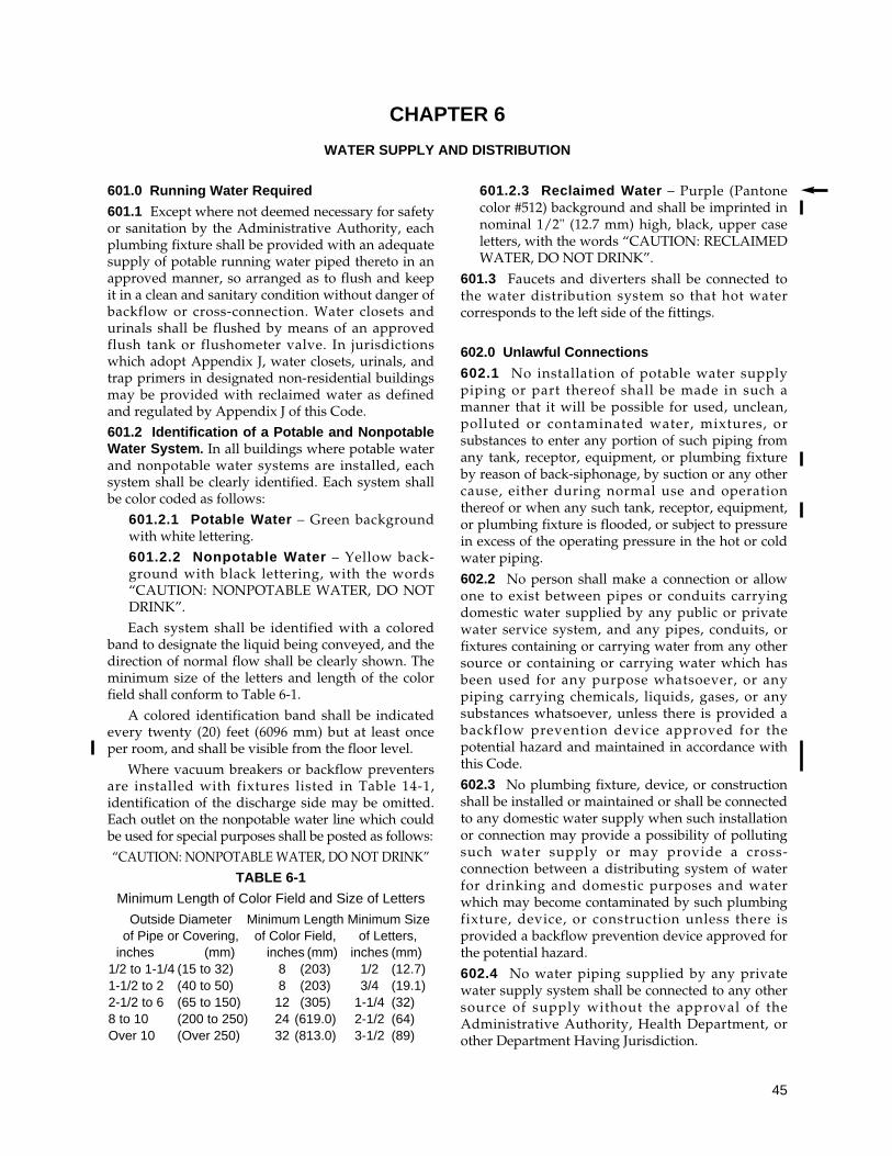
601.0 Running Water Required
601.1 Except where not deemed necessary for safetyor sanitation by the Administrative Authority, eachplumbing fixture shall be provided with an adequatesupply of potable running water piped thereto in anapproved manner, so arranged as to flush and keepit in a clean and sanitary condition without danger ofbackflow or cross-connection. Water closets andurinals shall be flushed by means of an approvedflush tank or flushometer valve. In jurisdictionswhich adopt Appendix J, water closets, urinals, andtrap primers in designated non-residential buildingsmay be provided with reclaimed water as definedand regulated by Appendix J of this Code.601.2 Identification of a Potable and NonpotableWater System. In all buildings where potable waterand nonpotable water systems are installed, eachsystem shall be clearly identified. Each system shallbe color coded as follows:
601.2.1 Potable Water – Green backgroundwith white lettering.601.2.2 Nonpotable Water – Yellow back-ground with black lettering, with the words“CAUTION: NONPOTABLE WATER, DO NOTDRINK”.Each system shall be identified with a colored
band to designate the liquid being conveyed, and thedirection of normal flow shall be clearly shown. Theminimum size of the letters and length of the colorfield shall conform to Table 6-1.
A colored identification band shall be indicatedevery twenty (20) feet (6096 mm) but at least onceper room, and shall be visible from the floor level.
Where vacuum breakers or backflow preventersare installed with fixtures listed in Table 14-1,identification of the discharge side may be omitted.Each outlet on the nonpotable water line which couldbe used for special purposes shall be posted as follows:“CAUTION: NONPOTABLE WATER, DO NOT DRINK”
TABLE 6-1
Minimum Length of Color Field and Size of Letters
Outside Diameter Minimum Length Minimum Sizeof Pipe or Covering, of Color Field, of Letters,
inches (mm) inches (mm) inches (mm)1/2 to 1-1/4 (15 to 32) 8 (203) 1/2 (12.7)1-1/2 to 2 (40 to 50) 8 (203) 3/4 (19.1)2-1/2 to 6 (65 to 150) 12 (305) 1-1/4 (32)8 to 10 (200 to 250) 24 (619.0) 2-1/2 (64)Over 10 (Over 250) 32 (813.0) 3-1/2 (89)
601.2.3 Reclaimed Water – Purple (Pantonecolor #512) background and shall be imprinted innominal 1/2" (12.7 mm) high, black, upper caseletters, with the words “CAUTION: RECLAIMEDWATER, DO NOT DRINK”.
601.3 Faucets and diverters shall be connected tothe water distribution system so that hot watercorresponds to the left side of the fittings.
602.0 Unlawful Connections
602.1 No installation of potable water supplypiping or part thereof shall be made in such amanner that it will be possible for used, unclean,polluted or contaminated water, mixtures, orsubstances to enter any portion of such piping fromany tank, receptor, equipment, or plumbing fixtureby reason of back-siphonage, by suction or any othercause, either during normal use and operationthereof or when any such tank, receptor, equipment,or plumbing fixture is flooded, or subject to pressurein excess of the operating pressure in the hot or coldwater piping.
602.2 No person shall make a connection or allowone to exist between pipes or conduits carryingdomestic water supplied by any public or privatewater service system, and any pipes, conduits, orfixtures containing or carrying water from any othersource or containing or carrying water which hasbeen used for any purpose whatsoever, or anypiping carrying chemicals, liquids, gases, or anysubstances whatsoever, unless there is provided abackflow prevention device approved for thepotential hazard and maintained in accordance withthis Code.
602.3 No plumbing fixture, device, or constructionshall be installed or maintained or shall be connectedto any domestic water supply when such installationor connection may provide a possibility of pollutingsuch water supply or may provide a cross-connection between a distributing system of waterfor drinking and domestic purposes and waterwhich may become contaminated by such plumbingfixture, device, or construction unless there isprovided a backflow prevention device approved forthe potential hazard.
602.4 No water piping supplied by any privatewater supply system shall be connected to any othersource of supply without the approval of theAdministrative Authority, Health Department, orother Department Having Jurisdiction.
45
CHAPTER 6
WATER SUPPLY AND DISTRIBUTION
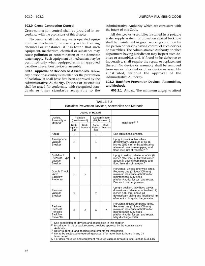
603.0 Cross-Connection Control
Cross-connection control shall be provided in ac-cordance with the provisions of this chapter.
No person shall install any water operated equip-ment or mechanism, or use any water treatingchemical or substance, if it is found that suchequipment, mechanism, chemical or substance maycause pollution or contamination of the domesticwater supply. Such equipment or mechanism may bepermitted only when equipped with an approvedbackflow prevention device or assembly.
603.1 Approval of Devices or Assemblies. Beforeany device or assembly is installed for the preventionof backflow, it shall have first been approved by theAdministrative Authority. Devices or assembliesshall be tested for conformity with recognized stan-dards or other standards acceptable to the
Administrative Authority which are consistent withthe intent of this Code.
All devices or assemblies installed in a potablewater supply system for protection against backflowshall be maintained in good working condition bythe person or persons having control of such devicesor assemblies. The Administrative Authority or otherdepartment having jurisdiction may inspect such de-vices or assemblies and, if found to be defective orinoperative, shall require the repair or replacementthereof. No device or assembly shall be removedfrom use or relocated or other device or assemblysubstituted, without the approval of theAdministrative Authority.
603.2 Backflow Prevention Devices, Assemblies,and Methods
603.2.1 Airgap. The minimum airgap to afford
UNIFORM PLUMBING CODE603.0 – 603.2
Device,Assembly orMethod1
Airgap
AtmosphericVacuumBreaker
Spill-ProofPressure-TypeVacuumBreaker
Double CheckValveBackflowPreventer
PressureVacuumBreaker
ReducedPressurePrincipleBackflowPreventer
1 See description of devices and assemblies in this chapter.2 Installation in pit or vault requires previous approval by the Administrative Authority.3 Refer to general and specific requirements for installation.4 Not to be subjected to operating pressure for more than 12 hours in any 24 hour period.5 For deck-mounted and equipment-mounted vacuum breakers, see Section 603.4.16.
TABLE 6-2Backflow Prevention Devices, Assemblies and Methods
See table in this chapter.
Upright position. No valvesdownstream. Minimum of six (6)inches (152 mm) or listed distanceabove all downstream piping andflood level rim of receptor.4, 5
Upright position. Minimum of six (6)inches (152 mm) or listed distanceabove all downstream piping andflood level rim of receptor.5
Horizontal, unless otherwise listed.Requires one (1) foot (305 mm)minimum clearance at bottom formaintenance. May needplatform/ladder for test and repair.Does not discharge water.
Upright position. May have valvesdownstream. Minimum of twelve (12)inches (305 mm) above alldownstream piping and flood level rimof receptor. May discharge water.
Horizontal unless otherwise listed.Requires one (1) foot (305 mm)minimum clearance at bottom formaintenance. May needplatform/ladder for test and repair.May discharge water.
Degree of Hazard
Pollution(Low Hazard)
Contamination(High Hazard)
Back-Siphon-
age
X
X
X
X
X
X
Back-Pressure
X
X
Back-Siphon-
age
X
X
X
X
X
Back-Pressure
X
Installation2, 3
46
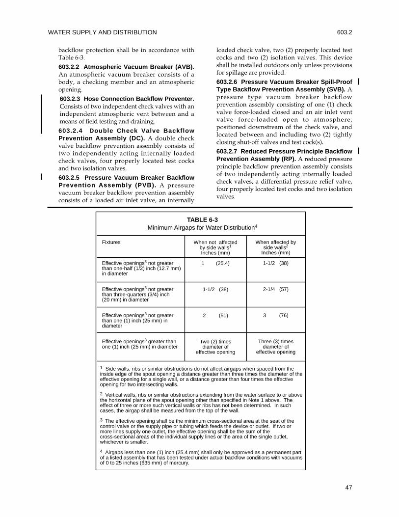
backflow protection shall be in accordance withTable 6-3.
603.2.2 Atmospheric Vacuum Breaker (AVB).An atmospheric vacuum breaker consists of abody, a checking member and an atmosphericopening.
603.2.3 Hose Connection Backflow Preventer.Consists of two independent check valves with anindependent atmospheric vent between and ameans of field testing and draining.
603.2.4 Double Check Valve BackflowPrevention Assembly (DC). A double checkvalve backflow prevention assembly consists oftwo independently acting internally loadedcheck valves, four properly located test cocksand two isolation valves.
603.2.5 Pressure Vacuum Breaker BackflowPrevention Assembly (PVB). A pressurevacuum breaker backflow prevention assemblyconsists of a loaded air inlet valve, an internally
loaded check valve, two (2) properly located testcocks and two (2) isolation valves. This deviceshall be installed outdoors only unless provisionsfor spillage are provided.
603.2.6 Pressure Vacuum Breaker Spill-ProofType Backflow Prevention Assembly (SVB). Apressure type vacuum breaker backflowprevention assembly consisting of one (1) checkvalve force-loaded closed and an air inlet ventvalve force-loaded open to atmosphere,positioned downstream of the check valve, andlocated between and including two (2) tightlyclosing shut-off valves and test cock(s).
603.2.7 Reduced Pressure Principle BackflowPrevention Assembly (RP). A reduced pressureprinciple backflow prevention assembly consistsof two independently acting internally loadedcheck valves, a differential pressure relief valve,four properly located test cocks and two isolationvalves.
WATER SUPPLY AND DISTRIBUTION 603.2
47
Fixtures
Effective openings3 not greaterthan one-half (1/2) inch (12.7 mm)in diameter
Effective openings3 not greaterthan three-quarters (3/4) inch(20 mm) in diameter
Effective openings3 not greaterthan one (1) inch (25 mm) indiameter
Effective openings3 greater thanone (1) inch (25 mm) in diameter
When not affectedby side walls1
Inches (mm)
1 (25.4)
1-1/2 (38)
2 (51)
Two (2) timesdiameter of
effective opening
When affected byside walls2
Inches (mm)
1-1/2 (38)
2-1/4 (57)
3 (76)
Three (3) timesdiameter of
effective opening
1 Side walls, ribs or similar obstructions do not affect airgaps when spaced from theinside edge of the spout opening a distance greater than three times the diameter of theeffective opening for a single wall, or a distance greater than four times the effectiveopening for two intersecting walls.
2 Vertical walls, ribs or similar obstructions extending from the water surface to or abovethe horizontal plane of the spout opening other than specified in Note 1 above. Theeffect of three or more such vertical walls or ribs has not been determined. In suchcases, the airgap shall be measured from the top of the wall.
3 The effective opening shall be the minimum cross-sectional area at the seat of thecontrol valve or the supply pipe or tubing which feeds the device or outlet. If two ormore lines supply one outlet, the effective opening shall be the sum of thecross-sectional areas of the individual supply lines or the area of the single outlet,whichever is smaller.
4 Airgaps less than one (1) inch (25.4 mm) shall only be approved as a permanent partof a listed assembly that has been tested under actual backflow conditions with vacuumsof 0 to 25 inches (635 mm) of mercury.
TABLE 6-3Minimum Airgaps for Water Distribution4
UNIFORM PLUMBING CODE
48
603.3 General Requirements
603.3.1 All assemblies shall conform to listedstandards and be acceptable to theAdministrative Authority having jurisdictionover the selection and installation of backflowprevention assemblies.
603.3.2 Where more than one (1) backflowprevention valve is installed on a single premise,and they are installed in one location, eachseparate valve shall be permanently identifiedby the permittee in a manner satisfactory to theAdministrative Authority.
603.3.3 The premise owner or responsibleperson shall have the backflow preventionassembly tested by a certified backflow assemblytester at the time of installation, repair, orrelocation and at least on an annual schedulethereafter or more often when required by theAdministrative Authority. The periodic testingshall be performed in accordance with theprocedures referenced in Table 14-1 by a testerqualified in accordance with those standards.
603.3.4 Access and clearance shall be providedfor the required testing, maintenance and repair.Access and clearance shall require a minimum ofone (1) foot (305 mm) between the lowestportion of the assembly and grade, floor orplatform. Installations elevated more than five(5) feet (1524 mm) above the floor or grade shallbe provided with a permanent platform capableof supporting a tester or maintenance person.
603.3.5 Direct connections between potablewater piping and sewer connected wastes shallnot exist under any condition with or withoutbackflow protection. Where potable water isdischarged to the drainage system it shall be bymeans of an approved airgap of two (2) pipediameters of the supply inlet, but in no case shallthe gap be less than one (1) inch (25 mm).Connection may be made to the inlet side of atrap provided that an approved vacuum breakeris installed not less than six (6) inches (152 mm)or the distance according to the device’s listing,above the flood level rim of such trapped fixture,so that at no time will any such device besubjected to any back-pressure.
603.3.6 Backflow preventers for hot water over110°F (43.3°C) shall be a listed type designed tooperate at temperatures of 110°F (43.3°C) ormore without rendering any portion of theassembly inoperative.
603.3.7 Fixtures, appliances or appurtenanceswith integral backflow preventers or integralairgaps manufactured as a unit shall be installed
in accordance with their listing requirementsand the manufacturers’ instructions.
603.3.8 In cold climate areas, backflowassemblies and devices shall be protected fromfreezing by a method acceptable to theAdministrative Authority.
603.4 Specific Requirements
603.4.1 Water Closet and Urinal FlushometerValves shall be equipped with a listedatmospheric vacuum breaker. The vacuumbreaker shall be installed on the discharge sideof the flushometer valve with the critical level atleast six (6) inches (152 mm) or the distance ac-cording to its listing above the overflow rim of awater closet bowl or the highest part of a urinal.
603.4.2 Water Closet and Urinal Tanks shall beequipped with a listed ballcock. The ballcockshall be installed with the critical level at leastone (1) inch (25.4 mm) above the full opening ofthe overflow pipe. In cases where the ballcockhas no hush tube, the bottom of the water supplyinlet shall be installed one (1) inch (25.4 mm)above the full opening of the overflow pipe.
603.4.3 Water Closet Flushometer Tanks shallbe protected against backflow by an approvedbackflow prevention assembly, device ormethod.
603.4.4 Heat Exchangers
603.4.4.1 Heat exchangers used for heattransfer, heat recovery, or solar heating shallprotect the potable water system from beingcontaminated by the heat transfer medium.Double-wall heat exchangers shall separatethe potable water from the heat transfermedium by providing a space between thetwo walls which is vented to the atmosphere.
603.4.4.2 For alternate design seeAppendix L.
603.4.5 Water supply inlets to tanks, vats,sumps, swimming pools and other receptorsshall be protected by one of the followingmeans:
1. An approved airgap;
2. A listed vacuum breaker installed on thedischarge side of the last valve with thecritical level not less than six (6) inches(152 mm) or in accordance with itslisting;
3. A backflow preventer suitable for thecontamination or pollution, installed inaccordance with the requirements forthat type of device or assembly as setforth in this chapter.
603.3 – 603.4
603.4.6 Protection from Lawn Sprinklers andIrrigation Systems
603.4.6.1 Potable water supplies to systemshaving no pumps or connections forpumping equipment, and no chemicalinjection or provisions for chemicalinjection, shall be protected from backflowby one of the following devices:
1. Atmospheric vacuum breaker
2. Pressure vacuum breaker
3. Reduced pressure backflow preventor
603.4.6.2 Where sprinkler and irrigationsystems have pumps, connections forpumping equipment, auxiliary air tanks orare otherwise capable of creating back-pressure, the potable water supply shall beprotected by the following type of device ifthe backflow device is located upstreamfrom the source of back-pressure.
1. Reduced pressure backflow preventor
603.4.6.3 Where systems have a backflowdevice installed downstream from a potablewater supply pump or a potable watersupply pump connection, the device shall beone of the following:
1. Atmospheric vacuum breaker
2. Pressure vacuum breaker
3. Reduced pressure backflow preventor
603.4.6.4 Where systems include achemical injector or any provisions forchemical injection, the potable water supplyshall be protected by the following:
1. Reduced pressure backflow preventor
603.4.7 Potable Water Outlets with HoseAttachments, other than water heater drains,boiler drains, and clothes washer connections,shall be protected by a listed non-removablehose bibb type backflow preventer, a listed non-removable hose bibb type vacuum breaker or bya listed atmospheric vacuum breaker installed atleast six (6) inches (152 mm) above the highestpoint of usage located on the discharge side ofthe last valve. In climates where freezingtemperatures occur, a listed self-draining frostproof hose bibb with an integral backflowpreventer or vacuum breaker shall be used.
603.4.8 Faucets with Pull-Out Spouts shall bein compliance with the appropriate standardslisted in Table 14-1 that include these specifictypes of faucets and require an atmosphericvacuum breaker or vent to atmosphere to protectthe water supply.
603.4.9 Water Cooled Compressors, De-greasers or any other water cooled equipmentshall be protected by a listed backflow preventerinstalled in accordance with the requirements ofthis chapter.
Note: Water cooled equipment whichproduces back-pressure shall be equippedwith the appropriate protection.
603.4.10 Water Inlets to Water SuppliedAspirators shall be equipped with a listedvacuum breaker installed in accordance with itslisting requirements and this chapter. Thedischarge shall drain through an airgap. Whenusing the tailpiece of a fixture to receive thedischarge of an aspirator, the airgap shall belocated above the flood level rim of the fixture.
603.4.11 Potable Water Make Up Connectionsto Steam or Hot Water Boilers shall be providedwith a listed backflow protection assembly.
603.4.12 Non-potable Water Piping. In caseswhere it is impractical to correct individual cross-connections on the domestic water line, the linesupplying such outlets shall be considered a non-potable water line. No drinking or domestic wateroutlets shall be connected to the non-potablewater line. Whenever possible, all portions of thenon-potable water line shall be exposed and allexposed portions shall be properly identified in amanner satisfactory to the AdministrativeAuthority. Each outlet on the non-potable waterline which may be used for drinking or domesticpurposes shall be posted: “CAUTION: NON-POTABLE WATER, DO NOT DRINK”.
603.4.13 Potable Water Supply to Carbonatorsshall be protected by either an airgap or a ventedbackflow preventer for carbonated beveragedispensers installed within the carbonatedbeverage dispenser. The carbonated beveragedispenser shall bear the label of an approvedtesting agency, certifying and attesting that suchequipment has been tested and inspected, andmeets the requirements of the approvedapplicable standard. Carbonated beveragedispensers without an approved internal airgapor vented backflow preventer for carbonatedbeverage dispensers and carbonated beveragedispensing systems shall have the water supplyprotected with a vented backflow preventer forcarbonated beverage dispensers.
603.4.14 Water Treatment Units. Reverseosmosis drinking water treatment units shallmeet the requirements of the appropriatestandard(s) referenced in Table 14-1. Waste ordischarge from reverse osmosis or other types of
WATER SUPPLY AND DISTRIBUTION 603.4
49
water treatment units shall enter the drainagesystem through an airgap.
603.4.15 Backflow Preventers shall not belocated in any area containing fumes that aretoxic, poisonous or corrosive.
603.4.16 Deck-Mounted or Equipment-Mounted Vacuum Breakers shall be installed inaccordance with their listing and themanufacturer's instructions, with the criticallevel not less than one (1) inch (25.4 mm) abovethe flood level rim.
603.4.17 Faucets with Hose-Attached Spraysshall vent to atmosphere under backsiphonageconditions.
603.4.18 Protection from Fire Systems
603.4.18.1 Except as provided underSections 603.4.18.2 and 603.4.18.3, potablewater supplies to fire protection systemsthat are normally under pressure, includingbut not limited to standpipes and automaticsprinkler systems, except in one or twofamily residential sprinkler systems piped inmaterials approved for potable waterdistribution systems, shall be protected fromback-pressure and back-siphonage by one ofthe following testable devices:
1. Double check valve assembly
2. Double check detector assembly
3. Reduced pressure backflow preventor
4. Reduced pressure detector assembly
Potable water supplies to fire protectionsystems that are not normally under pressureshall be protected from backflow and shallmeet the requirements of the appropriatestandard(s) referenced in Table 14-1.
603.4.18.2 Where fire protection systemssupplied from a potable water systeminclude a fire department (siamese)connection which is located less thanseventeen hundred (1700) feet (518.2 m)from a non-potable water source that couldbe used by the fire department as asecondary water supply, the potable watersupply shall be protected by one of thefollowing:
1. Reduced pressure backflow preventor
2. Reduced pressure detector assembly
Note: Non-potable water sources includefire department vehicles carrying water ofquestionable quality or water that is treatedwith antifreeze, corrosion inhibitors, orextinguishing agents.
603.4.18.3 Where antifreeze, corrosioninhibitors, or other chemicals are added to afire protection system supplied from apotable water supply, the potable watersystem shall be protected by one of thefollowing:
1. Reduced pressure backflow preventor
2. Reduced pressure detector assembly
603.4.18.4 Whenever a backflow device isinstalled in the potable water supply to afire protection system, the hydraulic designof the system shall account for the pressuredrop through the backflow device. If suchdevices are retrofitted for an existing fireprotection system, the hydraulics of thesprinkler system design shall be checked toverify that there will be sufficient waterpressure available for satisfactory operationof the fire sprinklers.
603.4.18.5 Residential SprinklerSystems. When residential sprinklersystems are installed using the potablewater system they shall be installed inaccordance with the standards listed inTable 14-1.
603.4.19 Special Equipment, Water SupplyProtection. Vacuum breakers for washer-hosebedpans shall be located not less than five (5)feet (1524 mm) above the floor. Hoseconnections in health care or laboratory areasshall not be less than six (6) feet (1829 mm)above the floor.
603.4.20 Portable cleaning equipment, dentalvacuum pumps and chemical dispensers shallbe protected from backflow by an airgap, anatmospheric vacuum breaker, a spill-proofvacuum breaker, or a reduced pressure principlebackflow preventer.
603.4.21 Water Heater Connectors. Flexiblemetallic water heater connectors or reinforcedflexible water heater connectors connectingwater heaters to the piping system shall be incompliance with the appropriate standardslisted in Table 14-1.
603.4.22 Combination stop-and-waste valves orcocks shall not be installed underground.
604.0 Materials
604.1 Water distribution pipe, building supplywater pipe and fittings shall be of brass, copper, castiron, galvanized malleable iron, galvanized wroughtiron, galvanized steel, or other approved materials.Asbestos-cement, CPVC, PE, PVC, or PEX water pipe
UNIFORM PLUMBING CODE
50
603.4 – 604.1
manufactured to recognized standards may be usedfor cold water distribution systems outside abuilding. CPVC, PEX water pipe, tubing, andfittings, manufactured to recognized standards maybe used for hot and cold water distribution systemswithin a building. All materials used in the watersupply system, except valves and similar devicesshall be of a like material, except where otherwiseapproved by the Administrative Authority.
604.2 Copper tube for water piping shall have aweight of not less than Type L.
Exception: Type M copper tubing may be usedfor water piping when piping is above groundin, or on, a building or underground outside ofstructures.
604.3 In addition to the required incised marking,all hard drawn copper tubing shall be marked bymeans of a continuous and indelibly colored stripe atleast one quarter (1/4) inch (6.4 mm) in width, asfollows: Type K, green; Type L, blue; Type M, red;Type DWV, yellow.
604.4 Listed flexible copper water connectors shallbe installed in readily accessible locations, unlessotherwise listed.
604.5 Cast iron fittings up to and including two (2)inches (51 mm) in size, when used in connectionwith potable water piping shall be galvanized.
604.6 All malleable iron water fittings shall begalvanized.
604.7 Piping and tubing which has previously beenused for any purpose other than for potable watersystems shall not be used.
604.8 Approved plastic materials may be used inwater service piping, provided that where metalwater service piping is used for electrical groundingpurposes, replacement piping therefore shall be oflike materials.
Exception: Where a grounding system,acceptable to the Administrative Authority isinstalled, inspected, and approved, metallic pipemay be replaced with non-metallic pipe.
604.9 Solder shall conform to the requirements ofSection 316.1.3.
604.10 Water pipe and fittings with a lead contentwhich exceeds eight (8) percent shall be prohibited inpiping systems used to convey potable water.
604.11 PEX. Cross-linked polyethylene (PEX)tubing shall be marked with the appropriatestandard designation(s) listed in Table 14-1 for whichthe tubing has been listed or approved. Pex tubingshall be installed in compliance with the provisionsof this section.
604.11.1 PEX Fittings. Metal Insert Fittingsand Metal Compression Fittings used with PEXtubing shall be manufactured to and marked inaccordance with the standards for the fittings inTable 14-1.
604.11.2 Water Heater Connections. PEXtubing shall not be installed within the firsteighteen (18) inches (457 mm) of pipingconnected to a water heater.
604.12 Flexible Corrugated Connectors. Flexiblecorrugated connectors of copper or stainless steelshall be limited to the following connector lengths:
Water Heater Connectors – twenty-four (24)inches (609 mm).
Fixture Connectors – thirty (30) inches (762 mm).
Washing Machine Connectors – seventy-two(72) inches (1827 mm).
Dishwasher and Icemaker Connectors – onehundred twenty (120) inches (3048 mm).
605.0 Valves
605.1 Valves up to and including two (2) inches (51mm) in size shall be brass or other approvedmaterial. Sizes over two (2) inches (51 mm) may havecast iron or brass bodies. Each gate or ball valve shallbe a fullway type with working parts of non-corrosive material.
605.2 A fullway valve controlling all outlets shall beinstalled on the discharge side of each water meter andon each unmetered water supply. Water pipingsupplying more than one building on any one premisesshall be equipped with a separate fullway valve to eachbuilding, so arranged that the water supply can beturned on or off to any individual or separate building;provided however, that supply piping to a singlefamily residence and building accessory thereto, maybe controlled on one valve. Such shutoff valves shall beaccessible at all times. A fullway valve shall be installedon the discharge piping from water supply tanks at ornear the tank. A fullway valve shall be installed on thecold water supply pipe to each water heater at or nearthe water heater.
605.3 In multi-dwelling units, one (1) or moreshutoff valves shall be provided in each dwellingunit so that the water supply to any plumbing fixtureor group of fixtures in that dwelling unit can be shutoff without stopping water supply to fixtures inother dwelling units. These valves shall be accessiblein the dwelling unit that they control.
605.4 All valves used to control two (2) or moreopenings shall be fullway gate valves, ball valves orother approved valves designed and approved forthe service intended.
WATER SUPPLY AND DISTRIBUTION
51
604.1 – 605.4
605.5 A control valve shall be installed immediatelyahead of each water supplied appliance andimmediately ahead of each slip joint or non-metallicfixture supply or appliance supply.
605.6 All required shutoff or control valves shall beaccessible.
605.7 A single control valve shall be installed on awater supply line ahead of any automatic meteringvalve which supplies a battery of fixtures.
606.0 Joints and Connections
606.1 Types of Joints
606.1.1 Flared Joints. Flared joints for softcopper water tubing shall be made with fittingsmeeting approved standards. The tubing shallbe reamed to the full bore, resized to round andexpanded with a proper flaring tool.
606.1.2 Mechanical Joints. Mechanical jointsfor cast iron water pipe shall conform tonationally recognized standards.
606.1.3 Mechanically Formed Tee Fittings.Mechanically extracted collars shall be formed ina continuous operation consisting of drilling apilot hole and drawing out the tube surface toform a collar having a height not less than three(3) times the thickness of the branch tube wall.
The branch tube shall be notched to conformwith the inner curve of the run tube and shallhave two (2) dimple/depth stops to insure thatpenetration of the branch tube into the collar is ofsufficient depth for brazing and that the branchtube does not obstruct the flow in the main linetube. Dimple/depth stops shall be in line withthe run of the tube. The second dimple shall beone quarter (1/4) inch (6.35 mm) above the firstand shall serve as a visual point of inspection.
All joints shall be brazed in accordance withSection 316.1.7. Soft soldered joints shall not beallowed.
606.2 Use of Joints
606.2.1 Copper Water Tube. Joints in coppertubing shall be made by the appropriate use ofapproved fittings properly soldered or brazedtogether as provided in Section 316.1.3 or 316.1.7or by means of approved flared or compressionfittings in Section 606.1.1 or 606.1.3. Solder andsoldering flux shall conform to the requirementsof Section 316.1.3. Mechanically formed teefittings shall be made by brazing only and shallconform to the requirements of Section 316.1.7.
606.2.2 Plastic Fittings. Female PVC screwedfittings for water piping shall be used with plasticmale fittings and plastic male threads only.
606.2.3 Slip Joints. In water piping, slip jointsmay be used only on the exposed fixture supply.
607.0 Gravity Supply Tanks
Gravity tanks for potable water shall be tightlycovered, and have not less than a sixteen (16) squareinch (10,323 mm2) overflow screened with copperscreen having not less than fourteen (14) nor morethan eighteen (18) openings per linear inch (25.4 mm).
608.0 Water Pressure, Pressure Regulators,Pressure Relief Valves, and Vacuum Relief Valves
608.1 Inadequate Water Pressure. Whenever thewater pressure in the main or other source of supplywill not provide a residual water pressure of at leastfifteen (15) pounds per square inch (103.4 kPa), afterallowing for friction and other pressure losses, a tankand a pump or other means which will provide saidfifteen (15) pound (103.4 kPa) pressure shall beinstalled. Whenever fixtures and/or fixture fittingsare installed, which require residual pressure higherthan fifteen (15) pounds per square inch (103.4 kPa),that minimum residual pressure shall be provided.
608.2 Excessive Water Pressure. Where localstatic water pressure is in excess of eighty (80)pounds per square inch (552 kPa), an approved typepressure regulator preceded by an adequate strainershall be installed and the static pressure reduced toeighty (80) pounds per square inch (552 kPa) or less.For potable water services up to and including oneand one-half (1-1/2) inch (40 mm) regulators,provision shall be made to prevent pressure on thebuilding side of the regulator from exceeding mainsupply pressure. Approved regulators with integralbypasses shall be acceptable. Each such regulatorand strainer shall be accessibly located and shallhave the strainer readily accessible for cleaningwithout removing the regulator or strainer body ordisconnecting the supply piping. All pipe sizedeterminations shall be based on eighty (80) percentof the reduced pressure when using Table 6-5.
608.3 Any water system provided with a checkvalve, backflow preventer or a pressure regulatingdevice which does not have a bypass feature at itssource shall be provided with an approved, listed,adequately sized pressure relief valve or a means tocontrol expansion.
Any water system containing storage waterheating equipment shall be provided with anapproved, listed, adequately sized combinationpressure and temperature relief valve, except forlisted non-storage instantaneous heaters having aninside diameter of not more than three (3) inches (80mm). Each such approved combination temperature
UNIFORM PLUMBING CODE
52
605.5 – 608.3
and pressure relief valve shall be installed on thewater heating device in an approved location basedon its listing requirements and the manufacturer'sinstructions. Each such combination temperatureand pressure relief valve shall be provided with adrain as required in Section 608.5.
In addition to the required pressure orcombination pressure and temperature relief valve, anapproved, listed expansion tank or other devicedesigned for intermittent operation for thermalexpansion control shall be installed whenever thebuilding supply pressure is greater than the requiredrelief valve pressure setting or when any device isinstalled that prevents pressure relief through thebuilding supply. The tank or device shall be sized inaccordance with the manufacturer’s recommendation.
608.4 Each pressure relief valve shall be anapproved automatic type with drain, and each suchrelief valve shall be set at a pressure of not more thanone hundred fifty (150) pounds per square inch (1035kPa). No shutoff valve shall be installed between therelief valve and the system or in the drain line.
608.5 Relief valves located inside a building shall beprovided with a drain, not smaller than the reliefvalve outlet, of galvanized steel, hard drawn copperpiping and fittings, CPVC, or listed relief valve draintube with fittings which will not reduce the internalbore of the pipe or tubing (straight lengths asopposed to coils) and shall extend from the valve tothe outside of the building with the end of the pipenot more than two (2) feet (610 mm) nor less than six(6) inches (152 mm) above the ground or the floodlevel of the area receiving the discharge and pointingdownward. Such drains may terminate at otherapproved locations. No part of such drain pipe shallbe trapped or subject to freezing. The terminal end ofthe drain pipe shall not be threaded.
608.6 Any water heating device connected to aseparate storage tank and having valves betweensaid heater and tank shall be provided with anapproved water pressure relief valve.
608.7 Vacuum Relief Valves. Where a hot waterstorage tank or an indirect water heater is located atan elevation above the fixture outlets in the hotwater system, a vacuum relief valve shall be installedon the storage tank or heater.
609.0 Installation, Testing, Unions, and Location
609.1 Installation. All water piping shall beadequately supported to the satisfaction of theAdministrative Authority. Burred ends shall bereamed to the full bore of the pipe or tube. Changesin direction shall be made by the appropriate use offittings, except that changes in direction in copper
tubing may be made with bends, provided that suchbends are made with bending equipment which doesnot deform or create a loss in the cross-sectional areaof the tubing. Changes in direction are allowed withflexible pipe and tubing without fittings inaccordance with the manufacturer's installationinstructions. Provisions shall be made for expansionin hot water piping. All piping, equipment,appurtenances, and devices shall be installed in aworkman-like manner in conformity with theprovisions and intent of the Code. All water serviceyard piping shall be at least twelve (12) inches (305mm) below the average local frost depth. Theminimum cover shall be twelve (12) inches (305 mm)below finish grade.
609.2 Water pipes shall not be run or laid in thesame trench as building sewer or drainage pipingconstructed of clay or materials which are notapproved for use within a building unless both ofthe following conditions are met:
609.2.1 The bottom of the water pipe, at allpoints, shall be at least twelve (12) inches (305mm) above the top of the sewer or drain line.
609.2.2 The water pipe shall be placed on asolid shelf excavated at one side of the commontrench with a minimum clear horizontal distanceof at least twelve (12) inches (305 mm) from thesewer or drain line.
Water pipes crossing sewer or drainage pipingconstructed of clay or materials which are notapproved for use within a building shall be laid aminimum of twelve (12) inches (305 mm) above thesewer or drain pipe.
609.3 Water piping installed within a building andin or under a concrete floor slab resting on theground shall be installed in accordance with thefollowing requirements:
609.3.1 Ferrous piping shall have a protectivecoating of an approved type, machine appliedand conforming to recognized standards. Fieldwrapping shall provide equivalent protectionand shall be restricted to those short sectionsand fittings necessarily stripped for threading.Zinc coating (galvanizing) shall not be deemedadequate protection for piping or fittings.Approved non-ferrous piping shall not berequired to be wrapped.
609.3.2 Copper tubing shall be installedwithout joints where possible. Where joints arepermitted, they shall be brazed and fittings shallbe wrought copper.
Note: For the purpose of this section, “within thebuilding” shall mean within the fixed limits ofthe building foundation.
WATER SUPPLY AND DISTRIBUTION
53
608.3 – 609.3
609.4 Testing. Upon completion of a section or ofthe entire hot and cold water supply system, it shallbe tested and proved tight under a water pressurenot less than the working pressure under which it isto be used. The water used for tests shall be obtainedfrom a potable source of supply. A fifty (50) poundper square inch (344.5 kPa) air pressure may besubstituted for the water test. In either method oftest, the piping shall withstand the test withoutleaking for a period of not less than fifteen (15)minutes.
609.5 Unions. Unions shall be installed in the watersupply piping within twelve (12) inches (305 mm) ofregulating equipment, water heating, conditioningtanks, and similar equipment which may requireservice by removal or replacement in a mannerwhich will facilitate its ready removal.
609.6 Location. Except as provided in Section 609.7,no building supply shall be located in any lot otherthan the lot which is the site of the building orstructure served by such building supply.
609.7 Nothing contained in this Code shall beconstrued to prohibit the use of all or part of anabutting lot to:
609.7.1 Provide access to connect a buildingsupply to an available public water service,when proper cause and legal easement not inviolation of other requirements have been firstestablished to the satisfaction of theAdministrative Authority.
609.7.2 Provide additional space for a buildingsupply when proper cause, transfer ofownership, or change of boundary not inviolation of other requirements have been firstestablished to the satisfaction of theAdministrative Authority. The instrumentrecording such action shall constitute anagreement with the Administrative Authority,which shall clearly state and show that the areasso joined or used shall be maintained as a unitduring the time they are so used. Such anagreement shall be recorded in the office of theCounty Recorder as a part of the conditions ofownership of said properties, and shall bebinding on all heirs, successors, and assigns tosuch properties. A copy of the instrumentrecording such proceedings shall be filed withthe Administrative Authority.
609.8 Low Pressure Cutoff Required on BoosterPumps for Water Distribution Systems. When abooster pump – excluding a fire pump – is connectedto a water service or underground water pipe, a low-pressure cutoff switch on the inlet side of the pumpshall be installed within five (5) feet (1524 mm) of the
inlet. The cutoff switch shall be set for not less thanten (10) psi (68.9 kPa) or as required by theAdministrative Authority. A pressure gauge shall beinstalled between the shutoff valve and the pump.
609.9 Disinfection of Potable Water System.New or repaired potable water systems shall bedisinfected prior to use whenever required by theAdministrative Authority. The method to befollowed shall be that prescribed by the healthauthority or, in case no method is prescribed bythem, the following:
609.9.1 The pipe system shall be flushed withclean, potable water until only potable waterappears at the points of outlet.
609.9.2 The system or parts thereof shall befilled with a water-chlorine solution containingat least fifty (50) parts per million of chlorine,and the system or part thereof shall be valved-off and allowed to stand for twenty-four (24)hours; or, the system or part thereof shall befilled with a water-chlorine solution containingat least two hundred (200) parts per million ofchlorine and allowed to stand for three (3) hours.
609.9.3 Following the allowed standing time,the system shall be flushed with clean, potablewater until the chlorine residual in the watercoming from the system does not exceed thechlorine residual in the flushing water.
609.9.4 The procedure shall be repeated if it isshown by bacteriological examination made byan approved agency that contamination persistsin the system.
609.10 Water Hammer. All building water supplysystems in which quick-acting valves are installedshall be provided with devices to absorb the hammercaused by high pressures resulting from the quickclosing of these valves. These pressure-absorbingdevices shall be either air chambers or approvedmechanical devices. Water pressure absorbingdevices shall be installed as close as possible toquick-acting valves.
609.10.1 Air Chambers. When air chambersare installed, they shall be in an accessible place,and each air chamber shall be provided with anaccessible means for restoring the air in theevent that the chamber becomes waterlogged.Air chambers shall be sized in accordance withTable 6-6.
609.10.2 Mechanical Devices. When listedmechanical devices are used, the manufacturer’sspecifications as to location and method ofinstallation shall be followed. Such mechanicaldevices shall be accessible.
UNIFORM PLUMBING CODE
54
609.4 – 609.10
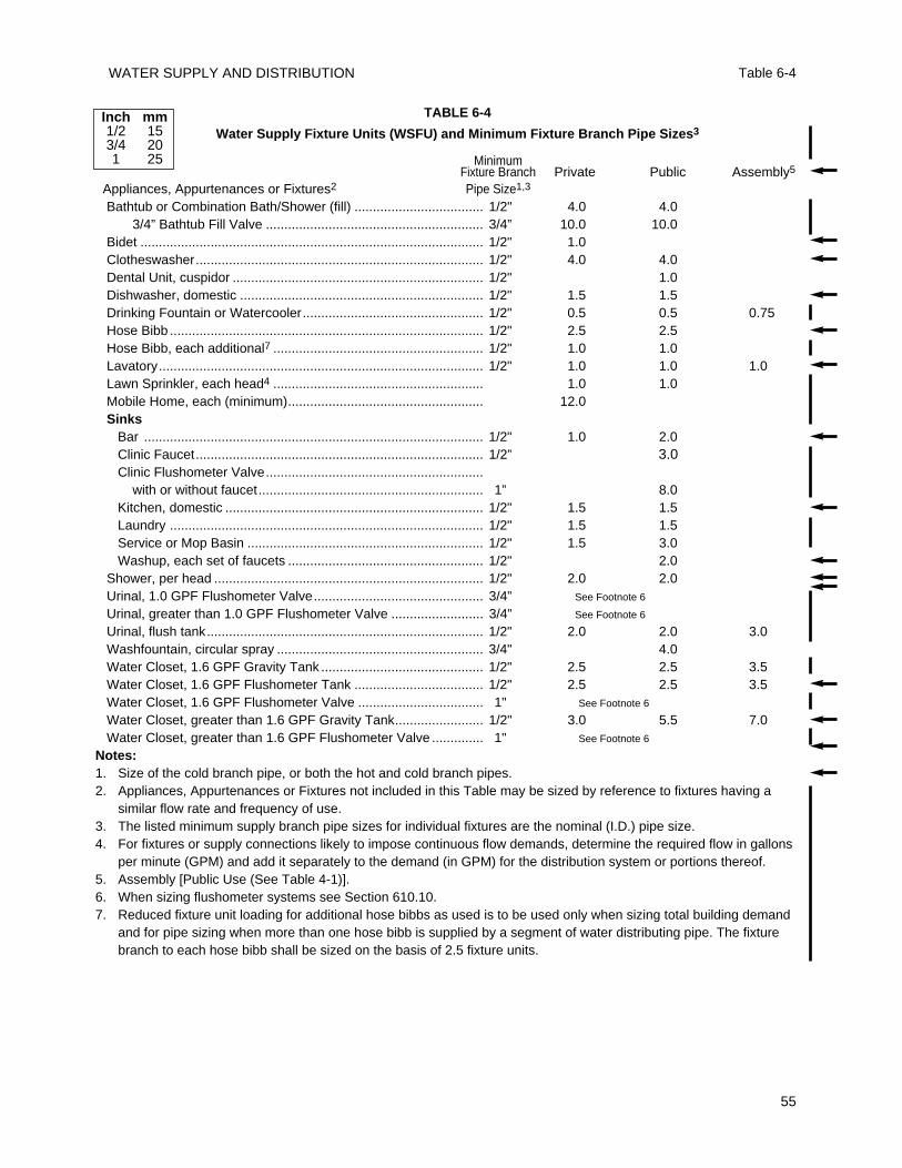
WATER SUPPLY AND DISTRIBUTION Table 6-4
55
TABLE 6-4
Water Supply Fixture Units (WSFU) and Minimum Fixture Branch Pipe Sizes3
MinimumFixture Branch Private Public Assembly5
Appliances, Appurtenances or Fixtures2 Pipe Size1,3
Bathtub or Combination Bath/Shower (fill) ................................... 1/2" 4.0 4.03/4” Bathtub Fill Valve ........................................................... 3/4” 10.0 10.0
Bidet ............................................................................................. 1/2" 1.0Clotheswasher.............................................................................. 1/2" 4.0 4.0Dental Unit, cuspidor .................................................................... 1/2" 1.0Dishwasher, domestic .................................................................. 1/2" 1.5 1.5Drinking Fountain or Watercooler................................................. 1/2" 0.5 0.5 0.75Hose Bibb ..................................................................................... 1/2" 2.5 2.5Hose Bibb, each additional7 ......................................................... 1/2" 1.0 1.0Lavatory........................................................................................ 1/2" 1.0 1.0 1.0Lawn Sprinkler, each head4 ......................................................... 1.0 1.0Mobile Home, each (minimum)..................................................... 12.0Sinks
Bar ............................................................................................ 1/2" 1.0 2.0Clinic Faucet.............................................................................. 1/2” 3.0Clinic Flushometer Valve...........................................................
with or without faucet............................................................. 1” 8.0Kitchen, domestic ...................................................................... 1/2" 1.5 1.5Laundry ..................................................................................... 1/2" 1.5 1.5Service or Mop Basin ................................................................ 1/2" 1.5 3.0Washup, each set of faucets ..................................................... 1/2" 2.0
Shower, per head ......................................................................... 1/2" 2.0 2.0Urinal, 1.0 GPF Flushometer Valve.............................................. 3/4” See Footnote 6
Urinal, greater than 1.0 GPF Flushometer Valve ......................... 3/4” See Footnote 6
Urinal, flush tank........................................................................... 1/2" 2.0 2.0 3.0Washfountain, circular spray ........................................................ 3/4" 4.0Water Closet, 1.6 GPF Gravity Tank ............................................ 1/2" 2.5 2.5 3.5Water Closet, 1.6 GPF Flushometer Tank ................................... 1/2" 2.5 2.5 3.5Water Closet, 1.6 GPF Flushometer Valve .................................. 1" See Footnote 6
Water Closet, greater than 1.6 GPF Gravity Tank........................ 1/2" 3.0 5.5 7.0Water Closet, greater than 1.6 GPF Flushometer Valve .............. 1" See Footnote 6
Notes:1. Size of the cold branch pipe, or both the hot and cold branch pipes.2. Appliances, Appurtenances or Fixtures not included in this Table may be sized by reference to fixtures having a
similar flow rate and frequency of use.3. The listed minimum supply branch pipe sizes for individual fixtures are the nominal (I.D.) pipe size.4. For fixtures or supply connections likely to impose continuous flow demands, determine the required flow in gallons
per minute (GPM) and add it separately to the demand (in GPM) for the distribution system or portions thereof.5. Assembly [Public Use (See Table 4-1)].6. When sizing flushometer systems see Section 610.10.7. Reduced fixture unit loading for additional hose bibbs as used is to be used only when sizing total building demand
and for pipe sizing when more than one hose bibb is supplied by a segment of water distributing pipe. The fixturebranch to each hose bibb shall be sized on the basis of 2.5 fixture units.
Inch mm1/2 153/4 201 25
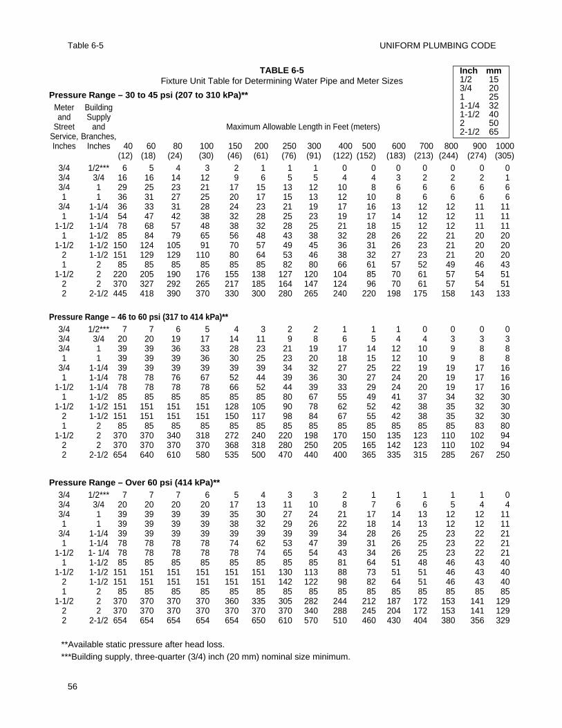
UNIFORM PLUMBING CODE
56
Table 6-5
TABLE 6-5Fixture Unit Table for Determining Water Pipe and Meter Sizes
Pressure Range – 30 to 45 psi (207 to 310 kPa)**Meter Buildingand Supply
Street and Maximum Allowable Length in Feet (meters)Service, Branches,Inches Inches 40 60 80 100 150 200 250 300 400 500 600 700 800 900 1000
(12) (18) (24) (30) (46) (61) (76) (91) (122) (152) (183) (213) (244) (274) (305)3/4 1/2*** 6 5 4 3 2 1 1 1 0 0 0 0 0 0 03/4 3/4 16 16 14 12 9 6 5 5 4 4 3 2 2 2 13/4 1 29 25 23 21 17 15 13 12 10 8 6 6 6 6 61 1 36 31 27 25 20 17 15 13 12 10 8 6 6 6 6
3/4 1-1/4 36 33 31 28 24 23 21 19 17 16 13 12 12 11 111 1-1/4 54 47 42 38 32 28 25 23 19 17 14 12 12 11 11
1-1/2 1-1/4 78 68 57 48 38 32 28 25 21 18 15 12 12 11 111 1-1/2 85 84 79 65 56 48 43 38 32 28 26 22 21 20 20
1-1/2 1-1/2 150 124 105 91 70 57 49 45 36 31 26 23 21 20 202 1-1/2 151 129 129 110 80 64 53 46 38 32 27 23 21 20 201 2 85 85 85 85 85 85 82 80 66 61 57 52 49 46 43
1-1/2 2 220 205 190 176 155 138 127 120 104 85 70 61 57 54 512 2 370 327 292 265 217 185 164 147 124 96 70 61 57 54 512 2-1/2 445 418 390 370 330 300 280 265 240 220 198 175 158 143 133
Pressure Range – 46 to 60 psi (317 to 414 kPa)**3/4 1/2*** 7 7 6 5 4 3 2 2 1 1 1 0 0 0 03/4 3/4 20 20 19 17 14 11 9 8 6 5 4 4 3 3 33/4 1 39 39 36 33 28 23 21 19 17 14 12 10 9 8 81 1 39 39 39 36 30 25 23 20 18 15 12 10 9 8 8
3/4 1-1/4 39 39 39 39 39 39 34 32 27 25 22 19 19 17 161 1-1/4 78 78 76 67 52 44 39 36 30 27 24 20 19 17 16
1-1/2 1-1/4 78 78 78 78 66 52 44 39 33 29 24 20 19 17 161 1-1/2 85 85 85 85 85 85 80 67 55 49 41 37 34 32 30
1-1/2 1-1/2 151 151 151 151 128 105 90 78 62 52 42 38 35 32 302 1-1/2 151 151 151 151 150 117 98 84 67 55 42 38 35 32 301 2 85 85 85 85 85 85 85 85 85 85 85 85 85 83 80
1-1/2 2 370 370 340 318 272 240 220 198 170 150 135 123 110 102 942 2 370 370 370 370 368 318 280 250 205 165 142 123 110 102 942 2-1/2 654 640 610 580 535 500 470 440 400 365 335 315 285 267 250
Pressure Range – Over 60 psi (414 kPa)**3/4 1/2*** 7 7 7 6 5 4 3 3 2 1 1 1 1 1 03/4 3/4 20 20 20 20 17 13 11 10 8 7 6 6 5 4 43/4 1 39 39 39 39 35 30 27 24 21 17 14 13 12 12 111 1 39 39 39 39 38 32 29 26 22 18 14 13 12 12 11
3/4 1-1/4 39 39 39 39 39 39 39 39 34 28 26 25 23 22 211 1-1/4 78 78 78 78 74 62 53 47 39 31 26 25 23 22 21
1-1/2 1- 1/4 78 78 78 78 78 74 65 54 43 34 26 25 23 22 211 1-1/2 85 85 85 85 85 85 85 85 81 64 51 48 46 43 40
1-1/2 1-1/2 151 151 151 151 151 151 130 113 88 73 51 51 46 43 402 1-1/2 151 151 151 151 151 151 142 122 98 82 64 51 46 43 401 2 85 85 85 85 85 85 85 85 85 85 85 85 85 85 85
1-1/2 2 370 370 370 370 360 335 305 282 244 212 187 172 153 141 1292 2 370 370 370 370 370 370 370 340 288 245 204 172 153 141 1292 2-1/2 654 654 654 654 654 650 610 570 510 460 430 404 380 356 329
**Available static pressure after head loss.***Building supply, three-quarter (3/4) inch (20 mm) nominal size minimum.
Inch mm1/2 153/4 201 251-1/4 321-1/2 402 502-1/2 65
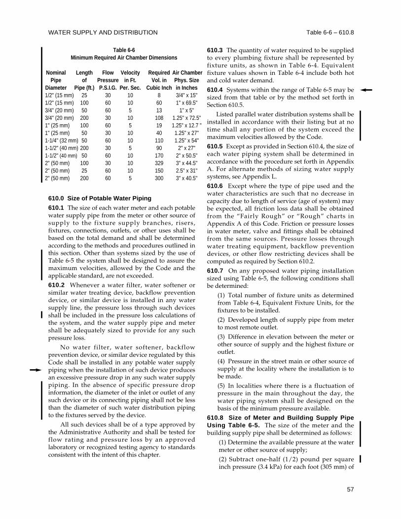
610.0 Size of Potable Water Piping
610.1 The size of each water meter and each potablewater supply pipe from the meter or other source ofsupply to the fixture supply branches, risers,fixtures, connections, outlets, or other uses shall bebased on the total demand and shall be determinedaccording to the methods and procedures outlined inthis section. Other than systems sized by the use ofTable 6-5 the system shall be designed to assure themaximum velocities, allowed by the Code and theapplicable standard, are not exceeded.
610.2 Whenever a water filter, water softener orsimilar water treating device, backflow preventiondevice, or similar device is installed in any watersupply line, the pressure loss through such devicesshall be included in the pressure loss calculations ofthe system, and the water supply pipe and metershall be adequately sized to provide for any suchpressure loss.
No water filter, water softener, backflowprevention device, or similar device regulated by thisCode shall be installed in any potable water supplypiping when the installation of such device producesan excessive pressure drop in any such water supplypiping. In the absence of specific pressure dropinformation, the diameter of the inlet or outlet of anysuch device or its connecting piping shall not be lessthan the diameter of such water distribution pipingto the fixtures served by the device.
All such devices shall be of a type approved bythe Administrative Authority and shall be tested forflow rating and pressure loss by an approvedlaboratory or recognized testing agency to standardsconsistent with the intent of this chapter.
610.3 The quantity of water required to be suppliedto every plumbing fixture shall be represented byfixture units, as shown in Table 6-4. Equivalentfixture values shown in Table 6-4 include both hotand cold water demand.
610.4 Systems within the range of Table 6-5 may besized from that table or by the method set forth inSection 610.5.
Listed parallel water distribution systems shall beinstalled in accordance with their listing but at notime shall any portion of the system exceed themaximum velocities allowed by the Code.
610.5 Except as provided in Section 610.4, the size ofeach water piping system shall be determined inaccordance with the procedure set forth in AppendixA. For alternate methods of sizing water supplysystems, see Appendix L.
610.6 Except where the type of pipe used and thewater characteristics are such that no decrease incapacity due to length of service (age of system) maybe expected, all friction loss data shall be obtainedfrom the “Fairly Rough” or “Rough” charts inAppendix A of this Code. Friction or pressure lossesin water meter, valve and fittings shall be obtainedfrom the same sources. Pressure losses throughwater treating equipment, backflow preventiondevices, or other flow restricting devices shall becomputed as required by Section 610.2.
610.7 On any proposed water piping installationsized using Table 6-5, the following conditions shallbe determined:
(1) Total number of fixture units as determinedfrom Table 6-4, Equivalent Fixture Units, for thefixtures to be installed.
(2) Developed length of supply pipe from meterto most remote outlet.
(3) Difference in elevation between the meter orother source of supply and the highest fixture oroutlet.
(4) Pressure in the street main or other source ofsupply at the locality where the installation is tobe made.
(5) In localities where there is a fluctuation ofpressure in the main throughout the day, thewater piping system shall be designed on thebasis of the minimum pressure available.
610.8 Size of Meter and Building Supply PipeUsing Table 6-5. The size of the meter and thebuilding supply pipe shall be determined as follows:
(1) Determine the available pressure at the watermeter or other source of supply;
(2) Subtract one-half (1/2) pound per squareinch pressure (3.4 kPa) for each foot (305 mm) of
WATER SUPPLY AND DISTRIBUTION Table 6-6 – 610.8
57
Table 6-6Minimum Required Air Chamber Dimensions
Nominal Length Flow Velocity Required Air ChamberPipe of Pressure in Ft. Vol. in Phys. Size
Diameter Pipe (ft.) P.S.I.G. Per. Sec. Cubic Inch in Inches1/2" (15 mm) 25 30 10 8 3/4" x 15"1/2" (15 mm) 100 60 10 60 1" x 69.5"3/4" (20 mm) 50 60 5 13 1" x 5"3/4" (20 mm) 200 30 10 108 1.25" x 72.5"1" (25 mm) 100 60 5 19 1.25" x 12.7 "1" (25 mm) 50 30 10 40 1.25" x 27"1-1/4" (32 mm) 50 60 10 110 1.25" x 54"1-1/2" (40 mm) 200 30 5 90 2" x 27"1-1/2" (40 mm) 50 60 10 170 2" x 50.5"2" (50 mm) 100 30 10 329 3" x 44.5"2" (50 mm) 25 60 10 150 2.5" x 31"2" (50 mm) 200 60 5 300 3" x 40.5"
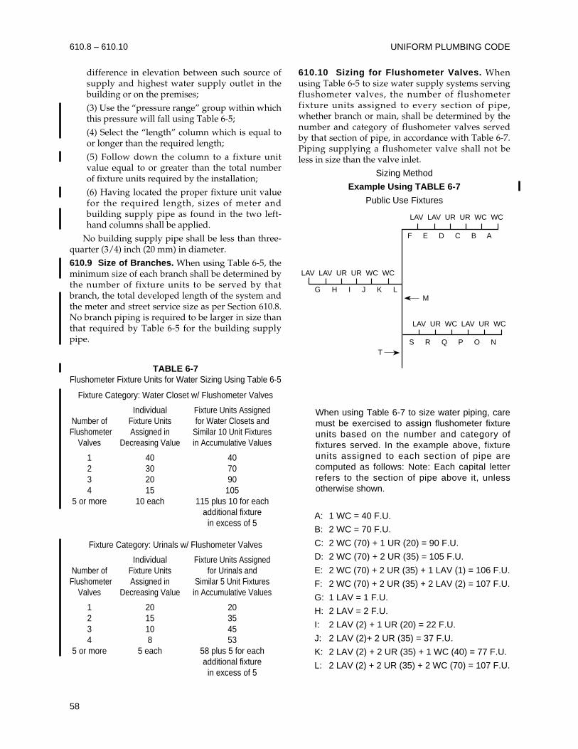
difference in elevation between such source ofsupply and highest water supply outlet in thebuilding or on the premises;
(3) Use the “pressure range” group within whichthis pressure will fall using Table 6-5;
(4) Select the “length” column which is equal toor longer than the required length;
(5) Follow down the column to a fixture unitvalue equal to or greater than the total numberof fixture units required by the installation;
(6) Having located the proper fixture unit valuefor the required length, sizes of meter andbuilding supply pipe as found in the two left-hand columns shall be applied.
No building supply pipe shall be less than three-quarter (3/4) inch (20 mm) in diameter.
610.9 Size of Branches. When using Table 6-5, theminimum size of each branch shall be determined bythe number of fixture units to be served by thatbranch, the total developed length of the system andthe meter and street service size as per Section 610.8.No branch piping is required to be larger in size thanthat required by Table 6-5 for the building supplypipe.
610.10 Sizing for Flushometer Valves. Whenusing Table 6-5 to size water supply systems servingflushometer valves, the number of flushometerfixture units assigned to every section of pipe,whether branch or main, shall be determined by thenumber and category of flushometer valves servedby that section of pipe, in accordance with Table 6-7.Piping supplying a flushometer valve shall not beless in size than the valve inlet.
Sizing Method
Example Using TABLE 6-7
Public Use Fixtures
When using Table 6-7 to size water piping, caremust be exercised to assign flushometer fixtureunits based on the number and category offixtures served. In the example above, fixtureunits assigned to each section of pipe arecomputed as follows: Note: Each capital letterrefers to the section of pipe above it, unlessotherwise shown.
A: 1 WC = 40 F.U.
B: 2 WC = 70 F.U.
C: 2 WC (70) + 1 UR (20) = 90 F.U.
D: 2 WC (70) + 2 UR (35) = 105 F.U.
E: 2 WC (70) + 2 UR (35) + 1 LAV (1) = 106 F.U.
F: 2 WC (70) + 2 UR (35) + 2 LAV (2) = 107 F.U.
G: 1 LAV = 1 F.U.
H: 2 LAV = 2 F.U.
I: 2 LAV (2) + 1 UR (20) = 22 F.U.
J: 2 LAV (2)+ 2 UR (35) = 37 F.U.
K: 2 LAV (2) + 2 UR (35) + 1 WC (40) = 77 F.U.
L: 2 LAV (2) + 2 UR (35) + 2 WC (70) = 107 F.U.
LAV LAV UR UR WC WC
LAV LAV UR UR WC WC
LAV UR WC LAV UR WC
T
M
F E D C B A
S R Q P O N
G H I J K L
UNIFORM PLUMBING CODE
58
610.8 – 610.10
TABLE 6-7Flushometer Fixture Units for Water Sizing Using Table 6-5
Fixture Category: Water Closet w/ Flushometer Valves
Individual Fixture Units AssignedNumber of Fixture Units for Water Closets andFlushometer Assigned in Similar 10 Unit Fixtures
Valves Decreasing Value in Accumulative Values
1 40 402 30 703 20 904 15 105
5 or more 10 each 115 plus 10 for eachadditional fixture
in excess of 5
Fixture Category: Urinals w/ Flushometer Valves
Individual Fixture Units AssignedNumber of Fixture Units for Urinals and Flushometer Assigned in Similar 5 Unit Fixtures
Valves Decreasing Value in Accumulative Values
1 20 202 15 353 10 454 8 53
5 or more 5 each 58 plus 5 for eachadditional fixture
in excess of 5
M: 4 WC (105) + 4 UR (53) + 4 LAV (4) = 162 F.U.
N: 1 WC = 40 F.U.
O: 1 WC (40) + 1 UR (20) = 60 F.U.
P: 1 WC (40) + 1 UR (20) + 1 LAV (1) = 61 F.U.
Q: 2 WC (70) + 1 UR (20) + 1 LAV (1) = 91 F.U.
R: 2 WC (70) + 2 UR (35) + 1 LAV (1) = 106 F.U.
S: 2 WC (70) + 2 UR (35) + 2 LAV (2) = 107 F.U.
T: 6 WC (125) + 6 UR (63) + 6 LAV (6) = 194 F.U.
610.11 Sizing Systems for Flushometer Tanks.The size of branches and mains serving flushometertanks shall be consistent with the sizing proceduresfor flush tank water closets.
610.12 Sizing for Velocity. Water piping systemsshall not exceed the maximum velocities listed in thissection or Appendix A.
610.12.1 Copper Tube Systems. Maximumvelocities in copper and copper alloy tube andfitting systems shall be limited to a maximum ofeight (8) feet per second (fps) (2.4 mps) in coldwater and five (5) fps in hot water (1.52 mps).
610.12.2 Tubing Systems Using CopperAlloy Fittings. Maximum velocities throughcopper alloy fittings in tubing other than coppershall be limited to a maximum of eight (8) feetper second (fps) (2.4 mps) in cold water and five(5) fps in hot water (1.52 mps).
610.13 Exceptions. The provisions of this sectionrelative to size of water piping shall not apply to thefollowing:
(1) Water supply piping systems designed inaccordance with recognized engineeringprocedures acceptable to the AdministrativeAuthority.
(2) Alteration of or minor additions to existinginstallations, provided the AdministrativeAuthority finds that there will be an adequatesupply of water to operate all fixtures.
(3) Replacement of existing fixtures orappliances.
(4) Piping which is part of fixture equipment.
(5) Unusual conditions where, in the judgementof the Administrative Authority, an adequatesupply of water is provided to operate fixturesand equipment.
(6) Non-potable water lines as defined inSections 601.2.2 and 601.2.3.
(7) The size and material of irrigation waterpiping installed outside of any building orstructure and separated from the potable watersupply by means of an approved airgap orbackflow prevention device is not regulated by
this Code. The potable water piping systemsupplying each such irrigation system shall beadequately sized as required elsewhere in thischapter to deliver the full connected demand ofboth the domestic use and the irrigation systems.
611.0 Drinking Water Treatment Units
611.1 Compliance with Standard. Drinking watertreatment units shall meet the requirements of theappropriate standard referenced in Table 14-1.
611.2 Airgap Discharge. Discharge from alldrinking water treatment units shall enter thedrainage system through an airgap or an airgapdevice which meets the requirements of theappropriate standards referenced in Table 14-1.
611.3 Connection Tubing. The tubing to and fromdrinking water treatment units shall be of a size andmaterial as recommended by the manufacturer. Thetubing shall comply with the requirements of theappropriate standards referenced in Table 14-1.
See also Appendix A, Recommended Rules forSizing the Water Supply System, and Appendix L,Alternate Plumbing Systems, for alternate methodsof sizing water supply systems.
WATER SUPPLY AND DISTRIBUTION 610.11 – 611.3
59

UNIFORM PLUMBING CODE
60
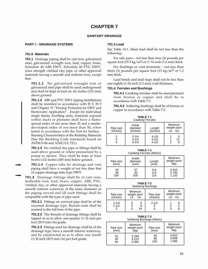
PART I – DRAINAGE SYSTEMS
701.0 Materials
701.1 Drainage piping shall be cast iron, galvanizedsteel, galvanized wrought iron, lead, copper, brass,Schedule 40 ABS DWV, Schedule 40 PVC DWV,extra strength vitrified clay pipe, or other approvedmaterials having a smooth and uniform bore, exceptthat:
701.1.1 No galvanized wrought iron orgalvanized steel pipe shall be used undergroundand shall be kept at least six (6) inches (152 mm)above ground.
701.1.2 ABS and PVC DWV piping installationsshall be installed in accordance with IS 5, IS 9and Chapter 15 “Firestop Protection for DWV andStormwater Application”. Except for individualsingle family dwelling units, materials exposedwithin ducts or plenums shall have a flame-spread index of not more then 25 and a smoke-developed index of not more than 50, whentested in accordance with the Test for Surface -Burning Characteristics of the Building Materials(See the Building Code standards based onASTM E-84 and ANSI/UL 723.).
701.1.3 No vitrified clay pipe or fittings shall beused above ground or where pressurized by apump or ejector. They shall be kept at leasttwelve (12) inches (305 mm) below ground.
701.1.4 Copper tube for drainage and ventpiping shall have a weight of not less than thatof copper drainage tube type DWV.
701.2 Drainage fittings shall be of cast iron,malleable iron, lead, brass, copper, ABS, PVC,vitrified clay, or other approved materials having asmooth interior waterway of the same diameter asthe piping served and all such fittings shall becompatible with the type of pipe used.
701.2.1 Fittings on screwed pipe shall be of therecessed drainage type. Burred ends shall bereamed to the full bore of the pipe.
701.2.2 The threads of drainage fittings shall betapped so as to allow one-quarter (1/4) inch perfoot (20.9 mm/m) grade.
701.2.3 Fittings used for drainage shall be of thedrainage type, have a smooth interior waterway,and be constructed so as to allow one fourth(1/4) inch (20.9 mm/m) per foot grade.
701.3 Lead
See Table 14-1. Sheet lead shall be not less than thefollowing:
For safe pans – not less than four (4) pounds persquare foot (19.5 kg/m2) or 1/16 inch (1.6 mm) thick.
For flashings or vent terminals – not less thanthree (3) pounds per square foot (15 kg/m2) or 1.2mm thick.
Lead bends and lead traps shall not be less thanone-eighth (1/8) inch (3.2 mm) wall thickness.
701.4 Ferrules and Bushings
701.4.1 Caulking ferrules shall be manufacturedfrom bronze or copper and shall be inaccordance with Table 7-1.
701.4.2 Soldering bushings shall be of bronze orcopper in accordance with Table 7-2.
61
CHAPTER 7
SANITARY DRAINAGE
TABLE 7-1Caulking Ferrules
TABLE 7-1Caulking Ferrules (Metric)
TABLE 7-2Soldering Bushings
TABLE 7-2Soldering Bushings (Metric)
Pipe size(inches)
234
Insidediameter(inches)
2-1/43-1/44-1/4
Length(inches)
4-1/24-1/24-1/2
Lb.
112
Oz.
012
8
Pipe size(mm)
Insidediameter
(mm)Length(mm)
114114114
Minimumweight each
(kg)
Pipe size(inches)
1-1/41-1/2
2
Minimumweight each Pipe size
(inches)
2-1/234
Minimumweight each
Lb.
123
Oz.
608
Pipe size(mm)
324050
Minimumweight each
(kg)
0.1680.2240.392
Pipe size(mm)
Minimumweight each
(kg)
Lb.
000
Oz.
68
14
6580
100
0.6220.9081.586
0.4540.7901.132
5783
108
5080
100
Minimumweight each
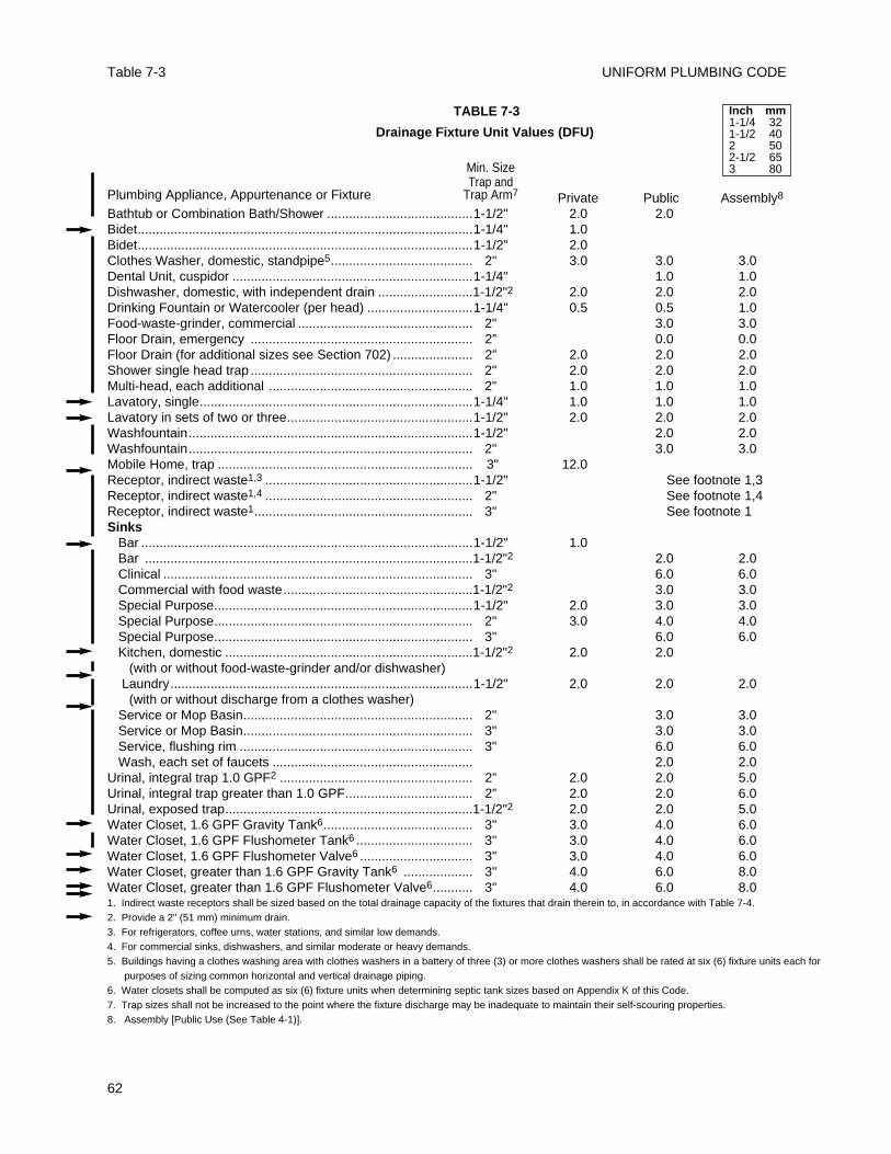
UNIFORM PLUMBING CODETable 7-3
62
TABLE 7-3
Drainage Fixture Unit Values (DFU)
Min. SizeTrap and
Plumbing Appliance, Appurtenance or Fixture Trap Arm7 Private Public Assembly8
Bathtub or Combination Bath/Shower ........................................1-1/2" 2.0 2.0Bidet............................................................................................1-1/4" 1.0Bidet............................................................................................1-1/2” 2.0Clothes Washer, domestic, standpipe5....................................... 2" 3.0 3.0 3.0Dental Unit, cuspidor ..................................................................1-1/4" 1.0 1.0Dishwasher, domestic, with independent drain ..........................1-1/2"2 2.0 2.0 2.0Drinking Fountain or Watercooler (per head) .............................1-1/4" 0.5 0.5 1.0Food-waste-grinder, commercial ................................................ 2" 3.0 3.0Floor Drain, emergency ............................................................. 2” 0.0 0.0Floor Drain (for additional sizes see Section 702) ...................... 2” 2.0 2.0 2.0Shower single head trap ............................................................. 2" 2.0 2.0 2.0Multi-head, each additional ........................................................ 2" 1.0 1.0 1.0Lavatory, single...........................................................................1-1/4" 1.0 1.0 1.0Lavatory in sets of two or three...................................................1-1/2" 2.0 2.0 2.0Washfountain..............................................................................1-1/2" 2.0 2.0Washfountain.............................................................................. 2" 3.0 3.0Mobile Home, trap ...................................................................... 3" 12.0Receptor, indirect waste1,3 .........................................................1-1/2" See footnote 1,3Receptor, indirect waste1,4 ......................................................... 2" See footnote 1,4 Receptor, indirect waste1............................................................ 3" See footnote 1Sinks
Bar ...........................................................................................1-1/2" 1.0Bar ..........................................................................................1-1/2"2 2.0 2.0Clinical ..................................................................................... 3" 6.0 6.0Commercial with food waste....................................................1-1/2"2 3.0 3.0Special Purpose.......................................................................1-1/2" 2.0 3.0 3.0Special Purpose....................................................................... 2" 3.0 4.0 4.0Special Purpose....................................................................... 3" 6.0 6.0Kitchen, domestic ....................................................................1-1/2"2 2.0 2.0
(with or without food-waste-grinder and/or dishwasher) Laundry...................................................................................1-1/2" 2.0 2.0 2.0(with or without discharge from a clothes washer)
Service or Mop Basin............................................................... 2" 3.0 3.0Service or Mop Basin............................................................... 3" 3.0 3.0Service, flushing rim ................................................................ 3" 6.0 6.0Wash, each set of faucets ....................................................... 2.0 2.0
Urinal, integral trap 1.0 GPF2 ..................................................... 2” 2.0 2.0 5.0Urinal, integral trap greater than 1.0 GPF................................... 2” 2.0 2.0 6.0Urinal, exposed trap....................................................................1-1/2"2 2.0 2.0 5.0Water Closet, 1.6 GPF Gravity Tank6......................................... 3" 3.0 4.0 6.0Water Closet, 1.6 GPF Flushometer Tank6 ................................ 3" 3.0 4.0 6.0Water Closet, 1.6 GPF Flushometer Valve6 ............................... 3" 3.0 4.0 6.0Water Closet, greater than 1.6 GPF Gravity Tank6 ................... 3" 4.0 6.0 8.0Water Closet, greater than 1.6 GPF Flushometer Valve6........... 3" 4.0 6.0 8.01. Indirect waste receptors shall be sized based on the total drainage capacity of the fixtures that drain therein to, in accordance with Table 7-4.2. Provide a 2" (51 mm) minimum drain.3. For refrigerators, coffee urns, water stations, and similar low demands.4. For commercial sinks, dishwashers, and similar moderate or heavy demands.5. Buildings having a clothes washing area with clothes washers in a battery of three (3) or more clothes washers shall be rated at six (6) fixture units each for
purposes of sizing common horizontal and vertical drainage piping.6. Water closets shall be computed as six (6) fixture units when determining septic tank sizes based on Appendix K of this Code.7. Trap sizes shall not be increased to the point where the fixture discharge may be inadequate to maintain their self-scouring properties.8. Assembly [Public Use (See Table 4-1)].
Inch mm1-1/4 321-1/2 402 502-1/2 653 80
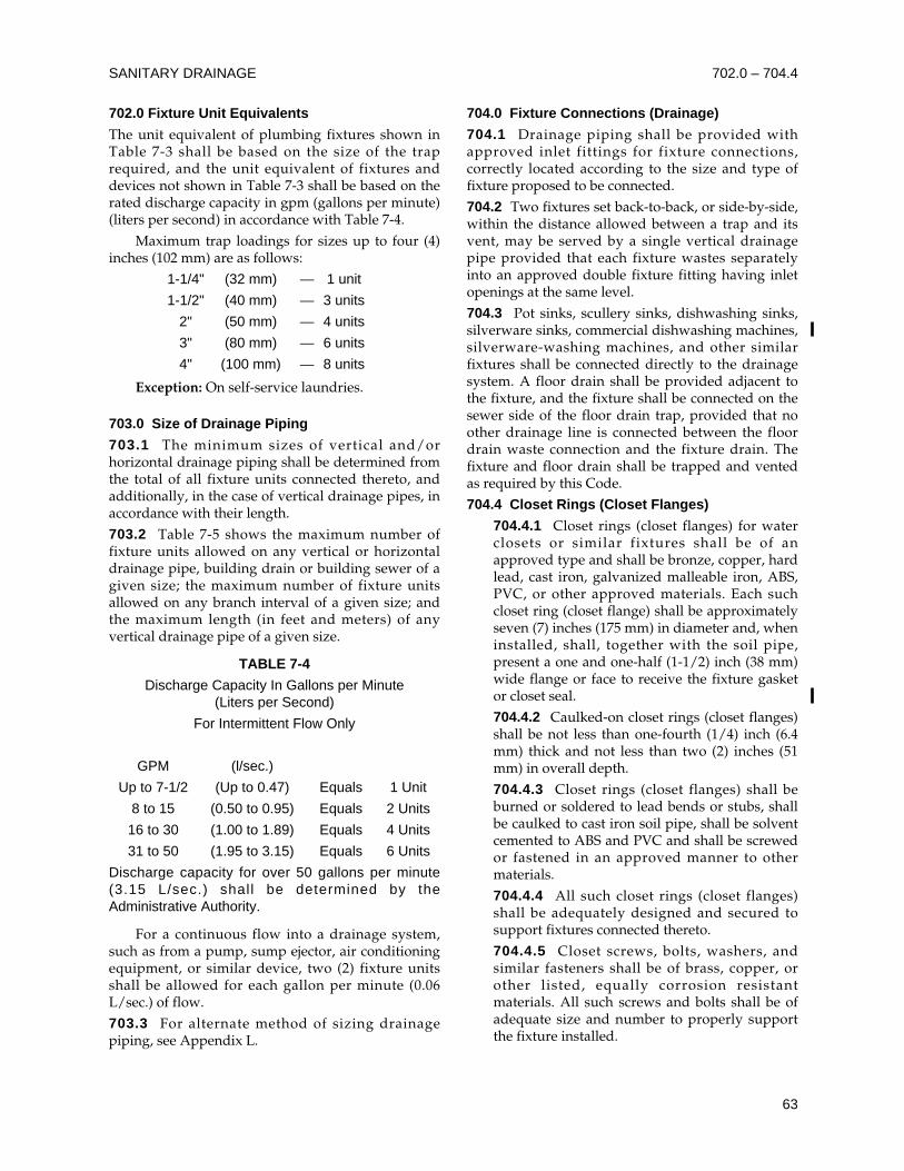
702.0 Fixture Unit Equivalents
The unit equivalent of plumbing fixtures shown inTable 7-3 shall be based on the size of the traprequired, and the unit equivalent of fixtures anddevices not shown in Table 7-3 shall be based on therated discharge capacity in gpm (gallons per minute)(liters per second) in accordance with Table 7-4.
Maximum trap loadings for sizes up to four (4)inches (102 mm) are as follows:
1-1/4" (32 mm) — 1 unit
1-1/2" (40 mm) — 3 units
2" (50 mm) — 4 units
3" (80 mm) — 6 units
4" (100 mm) — 8 units
Exception: On self-service laundries.
703.0 Size of Drainage Piping
703.1 The minimum sizes of vertical and/orhorizontal drainage piping shall be determined fromthe total of all fixture units connected thereto, andadditionally, in the case of vertical drainage pipes, inaccordance with their length.
703.2 Table 7-5 shows the maximum number offixture units allowed on any vertical or horizontaldrainage pipe, building drain or building sewer of agiven size; the maximum number of fixture unitsallowed on any branch interval of a given size; andthe maximum length (in feet and meters) of anyvertical drainage pipe of a given size.
TABLE 7-4
Discharge Capacity In Gallons per Minute (Liters per Second)
For Intermittent Flow Only
GPM (l/sec.)
Up to 7-1/2 (Up to 0.47) Equals 1 Unit
8 to 15 (0.50 to 0.95) Equals 2 Units
16 to 30 (1.00 to 1.89) Equals 4 Units
31 to 50 (1.95 to 3.15) Equals 6 Units
Discharge capacity for over 50 gallons per minute(3.15 L/sec.) shall be determined by theAdministrative Authority.
For a continuous flow into a drainage system,such as from a pump, sump ejector, air conditioningequipment, or similar device, two (2) fixture unitsshall be allowed for each gallon per minute (0.06L/sec.) of flow.
703.3 For alternate method of sizing drainagepiping, see Appendix L.
704.0 Fixture Connections (Drainage)
704.1 Drainage piping shall be provided withapproved inlet fittings for fixture connections,correctly located according to the size and type offixture proposed to be connected.
704.2 Two fixtures set back-to-back, or side-by-side,within the distance allowed between a trap and itsvent, may be served by a single vertical drainagepipe provided that each fixture wastes separatelyinto an approved double fixture fitting having inletopenings at the same level.
704.3 Pot sinks, scullery sinks, dishwashing sinks,silverware sinks, commercial dishwashing machines,silverware-washing machines, and other similarfixtures shall be connected directly to the drainagesystem. A floor drain shall be provided adjacent tothe fixture, and the fixture shall be connected on thesewer side of the floor drain trap, provided that noother drainage line is connected between the floordrain waste connection and the fixture drain. Thefixture and floor drain shall be trapped and ventedas required by this Code.
704.4 Closet Rings (Closet Flanges)
704.4.1 Closet rings (closet flanges) for waterclosets or similar fixtures shall be of anapproved type and shall be bronze, copper, hardlead, cast iron, galvanized malleable iron, ABS,PVC, or other approved materials. Each suchcloset ring (closet flange) shall be approximatelyseven (7) inches (175 mm) in diameter and, wheninstalled, shall, together with the soil pipe,present a one and one-half (1-1/2) inch (38 mm)wide flange or face to receive the fixture gasketor closet seal.
704.4.2 Caulked-on closet rings (closet flanges)shall be not less than one-fourth (1/4) inch (6.4mm) thick and not less than two (2) inches (51mm) in overall depth.
704.4.3 Closet rings (closet flanges) shall beburned or soldered to lead bends or stubs, shallbe caulked to cast iron soil pipe, shall be solventcemented to ABS and PVC and shall be screwedor fastened in an approved manner to othermaterials.
704.4.4 All such closet rings (closet flanges)shall be adequately designed and secured tosupport fixtures connected thereto.
704.4.5 Closet screws, bolts, washers, andsimilar fasteners shall be of brass, copper, orother listed, equally corrosion resistantmaterials. All such screws and bolts shall be ofadequate size and number to properly supportthe fixture installed.
SANITARY DRAINAGE 702.0 – 704.4
63
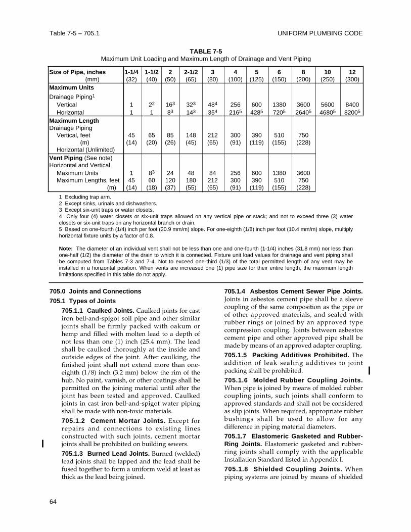
UNIFORM PLUMBING CODETable 7-5 – 705.1
64
705.0 Joints and Connections
705.1 Types of Joints
705.1.1 Caulked Joints. Caulked joints for castiron bell-and-spigot soil pipe and other similarjoints shall be firmly packed with oakum orhemp and filled with molten lead to a depth ofnot less than one (1) inch (25.4 mm). The leadshall be caulked thoroughly at the inside andoutside edges of the joint. After caulking, thefinished joint shall not extend more than one-eighth (1/8) inch (3.2 mm) below the rim of thehub. No paint, varnish, or other coatings shall bepermitted on the joining material until after thejoint has been tested and approved. Caulkedjoints in cast iron bell-and-spigot water pipingshall be made with non-toxic materials.
705.1.2 Cement Mortar Joints. Except forrepairs and connections to existing linesconstructed with such joints, cement mortarjoints shall be prohibited on building sewers.
705.1.3 Burned Lead Joints. Burned (welded)lead joints shall be lapped and the lead shall befused together to form a uniform weld at least asthick as the lead being joined.
705.1.4 Asbestos Cement Sewer Pipe Joints.Joints in asbestos cement pipe shall be a sleevecoupling of the same composition as the pipe orof other approved materials, and sealed withrubber rings or joined by an approved typecompression coupling. Joints between asbestoscement pipe and other approved pipe shall bemade by means of an approved adapter coupling.
705.1.5 Packing Additives Prohibited. Theaddition of leak sealing additives to jointpacking shall be prohibited.
705.1.6 Molded Rubber Coupling Joints.When pipe is joined by means of molded rubbercoupling joints, such joints shall conform toapproved standards and shall not be consideredas slip joints. When required, appropriate rubberbushings shall be used to allow for anydifference in piping material diameters.
705.1.7 Elastomeric Gasketed and Rubber-Ring Joints. Elastomeric gasketed and rubber-ring joints shall comply with the applicableInstallation Standard listed in Appendix I.
705.1.8 Shielded Coupling Joints. Whenpiping systems are joined by means of shielded
TABLE 7-5Maximum Unit Loading and Maximum Length of Drainage and Vent Piping
Size of Pipe, inches 1-1/4 1-1/2 2 2-1/2 3 4 5 6 8 10 12(mm) (32) (40) (50) (65) (80) (100) (125) (150) (200) (250) (300)
Maximum Units
Drainage Piping1
Vertical 1 22 163 323 484 256 600 1380 3600 5600 8400Horizontal 1 1 83 143 354 2165 4285 7205 26405 46805 82005
Maximum LengthDrainage Piping
Vertical, feet 45 65 85 148 212 300 390 510 750(m) (14) (20) (26) (45) (65) (91) (119) (155) (228)
Horizontal (Unlimited)Vent Piping (See note)Horizontal and Vertical
Maximum Units 1 83 24 48 84 256 600 1380 3600Maximum Lengths, feet 45 60 120 180 212 300 390 510 750
(m) (14) (18) (37) (55) (65) (91) (119) (155) (228)
1 Excluding trap arm.2 Except sinks, urinals and dishwashers.3 Except six-unit traps or water closets.4 Only four (4) water closets or six-unit traps allowed on any vertical pipe or stack; and not to exceed three (3) waterclosets or six-unit traps on any horizontal branch or drain.5 Based on one-fourth (1/4) inch per foot (20.9 mm/m) slope. For one-eighth (1/8) inch per foot (10.4 mm/m) slope, multiplyhorizontal fixture units by a factor of 0.8.
Note: The diameter of an individual vent shall not be less than one and one-fourth (1-1/4) inches (31.8 mm) nor less thanone-half (1/2) the diameter of the drain to which it is connected. Fixture unit load values for drainage and vent piping shallbe computed from Tables 7-3 and 7-4. Not to exceed one-third (1/3) of the total permitted length of any vent may beinstalled in a horizontal position. When vents are increased one (1) pipe size for their entire length, the maximum lengthlimitations specified in this table do not apply.
couplings, such couplings shall conform toapproved standards and shall not be consideredas slip joints.
705.1.9 Hubless Cast Iron Pipe Joints. Jointsfor hubless cast iron soil pipe and fittings shallconform to appropriate Installation Standardslisted in Appendix I and shall not be consideredas slip joints.
705.2 Use of Joints
705.2.1 Clay and Sewer Pipe. Joints in vitrifiedclay pipe or between such pipe and metal pipeshall be made as provided in Section 316.1.5,705.1.2, 705.1.6, or 705.1.8.
705.2.2 Cast Iron Pipe. Joints in cast iron pipeshall be made as provided in Section 316.1.1,316.1.5, 606.1.2, 705.1.1, 705.1.8 or 705.1.9.
705.2.3 Screw Pipe to Cast Iron. Jointsbetween wrought iron, steel, brass or copperpipe, and cast iron pipe shall be either caulkedor threaded joints made as provided in Section316.1.1 or 705.1.1, or shall be made withapproved adapter fittings.
705.2.4 Lead to Cast Iron, Wrought Iron orSteel. Joints between lead and cast iron,wrought iron or steel pipe shall be made bymeans of wiped joints to a caulking ferrule,soldering nipple or bushing as provided inSection 316.1.2.
705.3 Special Joints
705.3.1 Slip Joints. In fixture drains and traps,slip joints of approved materials may be used inaccordance with their approvals.
705.3.2 Expansion Joints. Expansion jointsshall be accessible, except when in vent pipingor drainage stacks, and may be used wherenecessary to provide for expansion andcontraction of the pipes.
705.3.3 Ground Joint, Flared or FerruleConnections. Brass or copper ground joint,flared or ferrule type connections which allowadjustment of tubing, but provide a rigid jointwhen made up, shall not be considered as slipjoints.
706.0 Changes in Direction of Drainage Flow
706.1 Changes in direction of drainage piping shallbe made by the appropriate use of approved fittingsand shall be of the angles presented by a one-sixteenth (1/16) bend, one-eighth (1/8) bend, or one-sixth (1/6) bend, or other approved fittings ofequivalent sweep.
706.2 Horizontal drainage lines, connecting with avertical stack, shall enter through forty-five (45)
degree (0.79 rad) wye branches, sixty (60) degree(1.05 rad) wye branches, combination wye and 1/8bend branches, sanitary tee or sanitary tapped teebranches, or other approved fittings of equivalentsweep. No fitting having more than one (1) inlet atthe same level shall be used unless such fitting isconstructed so that the discharge from one (1) inletcannot readily enter any other inlet. Double sanitarytees may be used when the barrel of the fitting is atleast two (2) pipe sizes larger than the largest inlet,(pipe sizes recognized for this purpose are 2", 2-1/2",3", 3-1/2", 4", 4-1/2", 5", 6", etc.) (50, 65, 80, 90, 100,115, 125, 150 mm, etc.).
706.3 Horizontal drainage lines connecting withother horizontal drainage lines shall enter throughforty-five (45) degree (0.79 rad) wye branches,combination wye and one-eighth (1/8) bend branches,or other approved fittings of equivalent sweep.
706.4 Vertical drainage lines connecting withhorizontal drainage lines shall enter through forty-five (45) degree (0.79 rad) wye branches,combination wye and one-eighth (1/8) bendbranches, or other approved fittings of equivalentsweep. Sixty (60) degree (1.05 rad) branches oroffsets may be used only when installed in a truevertical position.
707.0 Cleanouts
707.1 Each cleanout fitting for cast iron pipe shallconsist of a cast iron or brass body, and an approvedplug. Each cleanout for galvanized wrought iron,galvanized steel, copper, or brass pipe shall consistof a brass plug as specified in Table 7-6, or astandard weight brass cap, or an approved ABS orPVC plastic plug. Plugs shall have raised squareheads or approved counter-sunk rectangular slots.
707.2 Each cleanout fitting and each cleanout plugor cap shall be of an approved type. Materials usedfor cleanouts shall conform to approved standardsacceptable to the Administrative Authority.
707.3 Cleanouts shall be designed to be gas andwatertight.
707.4 Each horizontal drainage pipe shall beprovided with a cleanout at its upper terminal andeach run of piping, which is more than one hundred(100) feet (30480 mm) in total developed length, shallbe provided with a cleanout for each one hundred(100) feet (30480 mm), or fraction thereof, in length ofsuch piping.
Exceptions:
(1) Cleanouts may be omitted on a horizontaldrain line less than five (5) feet (1524 mm) inlength unless such line is serving sinks or urinals.
SANITARY DRAINAGE
65
705.1 – 707.4
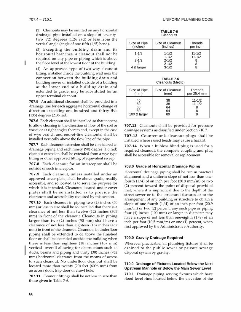
(2) Cleanouts may be omitted on any horizontaldrainage pipe installed on a slope of seventy-two (72) degrees (1.26 rad) or less from thevertical angle (angle of one-fifth (1/5) bend).
(3) Excepting the building drain and itshorizontal branches, a cleanout shall not berequired on any pipe or piping which is abovethe floor level of the lowest floor of the building.
(4) An approved type of two-way cleanoutfitting, installed inside the building wall near theconnection between the building drain andbuilding sewer or installed outside of a buildingat the lower end of a building drain andextended to grade, may be substituted for anupper terminal cleanout.
707.5 An additional cleanout shall be provided in adrainage line for each aggregate horizontal change ofdirection exceeding one hundred and thirty-five(135) degrees (2.36 rad).
707.6 Each cleanout shall be installed so that it opensto allow cleaning in the direction of flow of the soil orwaste or at right angles thereto and, except in the caseof wye branch and end-of-line cleanouts, shall beinstalled vertically above the flow line of the pipe.
707.7 Each cleanout extension shall be considered asdrainage piping and each ninety (90) degree (1.6 rad)cleanout extension shall be extended from a wye typefitting or other approved fitting of equivalent sweep.
707.8 Each cleanout for an interceptor shall beoutside of such interceptor.
707.9 Each cleanout, unless installed under anapproved cover plate, shall be above grade, readilyaccessible, and so located as to serve the purpose forwhich it is intended. Cleanouts located under coverplates shall be so installed as to provide theclearances and accessibility required by this section.
707.10 Each cleanout in piping two (2) inches (50mm) or less in size shall be so installed that there is aclearance of not less than twelve (12) inches (305mm) in front of the cleanout. Cleanouts in pipinglarger than two (2) inches (50 mm) shall have aclearance of not less than eighteen (18) inches (457mm) in front of the cleanout. Cleanouts in underfloorpiping shall be extended to or above the finishedfloor or shall be extended outside the building whenthere is less than eighteen (18) inches (457 mm)vertical overall allowing for obstructions such asducts, beams and piping and thirty (30) inches (762mm) horizontal clearance from the means of accessto such cleanout. No underfloor cleanout shall belocated more than twenty (20) feet (6096 mm) froman access door, trap door or crawl hole.
707.11 Cleanout fittings shall be not less in size thanthose given in Table 7-6.
707.12 Cleanouts shall be provided for pressuredrainage systems as classified under Section 710.7.
707.13 Countersunk cleanout plugs shall beinstalled where raised heads may cause a hazard.
707.14 When a hubless blind plug is used for arequired cleanout, the complete coupling and plugshall be accessible for removal or replacement.
708.0 Grade of Horizontal Drainage Piping
Horizontal drainage piping shall be run in practicalalignment and a uniform slope of not less than one-fourth (1/4) of an inch per foot (20.9 mm/m) or two(2) percent toward the point of disposal providedthat, where it is impractical due to the depth of thestreet sewer or to the structural features or to thearrangement of any building or structure to obtain aslope of one-fourth (1/4) of an inch per foot (20.9mm/m) or two (2) percent, any such pipe or pipingfour (4) inches (100 mm) or larger in diameter mayhave a slope of not less than one-eighth (1/8) of aninch per foot (10.5 mm/m) or one (1) percent, whenfirst approved by the Administrative Authority.
709.0 Gravity Drainage Required
Wherever practicable, all plumbing fixtures shall bedrained to the public sewer or private sewagedisposal system by gravity.
710.0 Drainage of Fixtures Located Below the NextUpstream Manhole or Below the Main Sewer Level
710.1 Drainage piping serving fixtures which haveflood level rims located below the elevation of the
TABLE 7-6Cleanouts
TABLE 7-6Cleanouts (Metric)
Size of Pipe(inches)
1-1/22
2-1/23
4 & larger
Size of Cleanout(inches)
1-1/21-1/22-1/22-1/23-1/2
Threadsper inch
11-1/211-1/2
888
Size of Pipe(mm)
40506580
100 & larger
Size of Cleanout(mm)
3838646489
Threadsper 25.4 mm
11-1/211-1/2
888
UNIFORM PLUMBING CODE
66
707.4 – 710.1
next upstream manhole cover of the public or privatesewer serving such drainage piping shall beprotected from backflow of sewage by installing anapproved type backwater valve. Fixtures above suchelevation shall not discharge through the backwatervalve.
710.2 Drainage piping serving fixtures that arelocated below the crown level of the main sewershall discharge into an approved watertight sump orreceiving tank, so located as to receive the sewage orwastes by gravity. From such sump or receivingtank, the sewage or other liquid wastes shall be liftedand discharged into the building drain or buildingsewer by approved ejectors, pumps, or other equallyefficient approved mechanical device.
710.3 A sewage ejector or sewage pump receivingthe discharge of water closets or urinals:
710.3.1 Shall have a minimum dischargecapacity of twenty (20) gallons (75.7 liters) perminute.
710.3.2 In single dwelling units, the ejector orpump shall be capable of passing a one and one-half (1-1/2) inch (38 mm) diameter solid ball,and the discharge piping of each ejector orpump shall have a backwater valve and gatevalve, and be a minimum of two (2) inches (51mm) in diameter.
710.3.3 In other than single dwelling units, theejector or pump shall be capable of passing atwo (2) inches (51 mm) diameter solid ball, andthe discharge piping of each ejector or pumpshall have a backwater valve and gate valve, andbe a minimum of three (3) inches (80 mm) indiameter.
710.4 The discharge line from such ejector, pump,or other mechanical device shall be provided with anaccessible backwater or swing check valve and gateor ball valve. If the gravity drainage line to whichsuch discharge line connects is horizontal, themethod of connection shall be from the top througha wye branch fitting. The gate or ball valve shall belocated on the discharge side of the backwater orcheck valve.
Gate or ball valves, when used on drainagework, shall be full way type with working parts ofcorrosion resistant metal. Sizes four (4) inches(100mm) or more in diameter shall have cast ironbodies, and sizes less than four (4) inches (100 mm),cast iron or brass bodies.
710.5 Building drains or building sewers receivingdischarge from any pump or ejector shall beadequately sized to prevent overloading. Two (2)fixture units shall be allowed for each gallon perminute (0.06 L/s) of flow.
710.6 Backwater valves, gate valves, fullway ballvalves, unions, motors, compressors, air tanks, andother mechanical devices required by this sectionshall be located where they will be accessible forinspection and repair at all times and, unlesscontinuously exposed, shall be enclosed in amasonry pit fitted with an adequately sizedremovable cover.
Backwater valves shall have bodies of cast iron,plastic, brass, or other approved materials, non-corrosive bearings, seats and self-aligning discs, andshall be so constructed as to insure a positivemechanical seal. Such backwater valves shall remainsufficiently open during periods of low flows toavoid screening of solids and shall not restrictcapacities or cause excessive turbulence during peakloads. Unless otherwise listed, valve access coversshall be bolted type with gasket and each valve shallbear the manufacturer's name cast into body andcover.
710.7 The drainage and venting systems inconnection with fixtures, sumps, receiving tanks, andmechanical waste lifting devices, shall be installedunder the same requirements as provided for in thisCode for gravity systems.
710.8 Sumps and receiving tanks shall be watertightand shall be constructed of concrete, metal, or otherapproved materials. If constructed of pouredconcrete, the walls and bottom shall be adequatelyreinforced and designed to recognized acceptablestandards. Metal sumps or tanks shall be of suchthickness as to serve their intended purpose andshall be treated internally and externally to resistcorrosion.
710.9 All such sumps and receiving tanks shall beautomatically discharged and, when in any “publicuse” occupancy, shall be provided with dual pumpsor ejectors arranged to function independently incase of overload or mechanical failure. The lowestinlet shall have a minimum clearance of two (2)inches (51 mm) from the high water or “starting”level of the sump.
710.10 Sumps and receiving tanks shall be providedwith substantial covers having a bolt and gasket typemanhole or equivalent opening to permit access forinspection, repairs, and cleaning. The top shall beprovided with a vent pipe which shall extendseparately through the roof, or when permitted, maybe combined with other vent pipes. Such vent shallbe large enough to maintain atmospheric pressurewithin the sump under all normal operatingconditions and, in no case, shall be less in size thanthat required by Table 7-5 for the number and typeof fixtures discharging into the sump, nor less thanone and one-half (1-1/2) inches (40 mm) in diameter.
SANITARY DRAINAGE
67
710.1 – 710.10
UNIFORM PLUMBING CODE710.10 – 713.1
68
When the foregoing requirements are met and thevent, after leaving the sump, is combined with ventsfrom fixtures discharging into the sump, the size ofthe combined vent need not exceed that required forthe total number of fixtures discharging into thesump. No vent from an air-operating sewage ejectorshall combine with other vents.
710.11 Air tanks shall be so proportioned as to be ofequal cubical capacity to the ejectors connectedtherewith in which there shall be maintained an airpressure of not less than two (2) pounds for each foot(3 kg for each m) of height the sewage is to be raised.No water operated ejectors shall be permitted.
710.12 When subsoil drainage systems are installed,such systems shall be discharged into an approvedsump or receiving tank and shall be discharged in amanner satisfactory to the Administrative Authority.
710.13 Grinder Pump Ejector. With the approvalof the Administrative Authority, a grinder pumpmay be used.
710.14 Macerating Toilet Systems. Listedmacerating toilet systems shall be permitted as analternate to a sewage pump system for singlebathrooms for private use when approved by theAdministrative Authority.
710.14.1 Sumps. The sump shall be water andgas tight.
710.14.2 Discharge Piping. The dischargepiping shall be sized per manufacturer’sinstructions and shall be not less than 3/4" (20mm) in diameter. The developed length of thedischarge piping shall not exceed manufacturer’srecommendations. A check valve and fullwaytype shutoff valve shall be located within thedischarge line or internally within the device.
710.14.3 Venting. The plumbing fixtures whichdischarge into the macerating device shall bevented per this code. The sump shall be ventedper manufacturer’s instructions and such ventshall be permitted to connect to the fixtureventing.
711.0 Suds Relief
Drainage connections shall not be made into adrainage piping system within eight (8) feet (2438mm) of any vertical to horizontal change of directionof a stack containing suds-producing fixtures.Bathtubs, laundries, washing machine stand pipes,kitchen sinks and dishwashers shall be consideredsuds-producing fixtures. Where parallel vent stacksare required, they shall connect to the drainage stackat a point eight (8) feet (2438 mm) above the lowestpoint of the drainage stack.
Exceptions:
(1) Single family residences.
(2) Stacks receiving the discharge from less thanthree (3) stories of plumbing fixtures.
712.0 Testing
712.1 Media. The piping of the plumbing, drainage,and venting systems shall be tested with water or air.The Administrative Authority may require theremoval of any cleanouts, etc., to ascertain if thepressure has reached all parts of the system. Afterthe plumbing fixtures have been set and their trapsfilled with water, they shall be submitted to a finaltest.
712.2 Water Test. The water test shall be applied tothe drainage and vent systems either in its entirety orin sections. If applied to the entire system, allopenings in the piping shall be tightly closed, exceptthe highest opening, and the system filled with waterto point of overflow. If the system is tested insections, each opening shall be tightly pluggedexcept the highest opening of the section under test,and each section shall be filled with water, but nosection shall be tested with less than a ten (10) foot(3048 mm) head of water. In testing successivesections, at least the upper ten (10) feet (3048 mm) ofthe next preceding section shall be tested, so that nojoint or pipe in the building (except the uppermostten (10) feet (3048 mm) of the system) shall havebeen submitted to a test of less than a ten (10) foot(3048 mm) head of water. The water shall be kept inthe system, or in the portion under test, for at leastfifteen (15) minutes before inspection starts. Thesystem shall then be tight at all points.
712.3 Air Test. The air test shall be made byattaching an air compressor testing apparatus to anysuitable opening, and, after closing all other inletsand outlets to the system, forcing air into the systemuntil there is a uniform gage pressure of five (5)pounds per square inch (34.5 kPa) or sufficient tobalance a column of mercury ten (10) inches (254mm) in height. The pressure shall be held withoutintroduction of additional air for a period of at leastfifteen (15) minutes.
PART II – BUILDING SEWERS
713.0 Sewer Required
713.1 Every building in which plumbing fixturesare installed and every premises having drainagepiping thereon, shall have a connection to a public orprivate sewer, except as provided in Sections101.4.1.3, 713.2 and 713.4.
713.2 When no public sewer, intended to serve anylot or premises, is available in any thoroughfare orright of way abutting such lot or premises, drainagepiping from any building or works shall beconnected to an approved private sewage disposalsystem.
713.3 Within the limits prescribed by Section 713.4hereof, the rearrangement or subdivision intosmaller parcels of a lot which abuts and is served bya public sewer shall not be deemed cause to permitthe construction of a private sewage disposal system,and all plumbing or drainage systems on any suchsmaller parcel or parcels shall connect to the publicsewer.
713.4 The public sewer may be considered as notbeing available when such public sewer or anybuilding or any exterior drainage facility connectedthereto, is located more than two hundred (200) feet(60.8 m) from any proposed building or exteriordrainage facility on any lot or premises which abutsand is served by such public sewer.
713.5 No permit shall be issued for the installation,alteration, or repair of any private sewage disposalsystem, or part thereof, on any lot for which aconnection with a public sewer is available.
713.6 On every lot or premises hereafter connectedto public sewer, all plumbing and drainage systemsor parts thereof, on such lot or premises shall beconnected with such public sewer.
Exception: Single family dwellings andbuildings or structures accessory thereto,existing and connected to an approved privatesewage disposal system prior to the time ofconnecting the premises to public sewer may,when no hazard, nuisance, or insanitarycondition is evidenced and written permissionhas been obtained from the AdministrativeAuthority, remain connected to such properlymaintained private sewage disposal systemwhen there is insufficient grade or fall to permitdrainage to the sewer by gravity.
714.0 Damage to Public Sewer or Private SewageDisposal System
714.1 It shall be unlawful for any person to deposit,by any means whatsoever, into any plumbingfixture, floor drain, interceptor, sump, receptor ordevice which is connected to any drainage system,public sewer, private sewer, septic tank, or cesspool,any ashes, cinders, solids, rags, flammable,poisonous, or explosive liquids or gases, oils, grease,and any other thing whatsoever which would orcould cause damage to the public sewer, privatesewer, or private sewage disposal system.
714.2 No rain, surface, or subsurface water shall beconnected to or discharged into any drainagesystem, unless first approved by the AdministrativeAuthority.
714.3 No cesspool, septic tank, seepage pit, ordrainfield shall be connected to any public sewer orto any building sewer leading to such public sewer.
714.4 No commercial food waste grinder shall beconnected to a private sewage disposal systemunless permission has first been obtained from theAdministrative Authority.
714.5 An approved type watertight sewage or wastewater holding tank, the contents of which, due totheir character, must be periodically removed anddisposed of at some approved off-site location, shallbe installed only when required by theAdministrative Authority or the Health Officer toprevent anticipated surface or subsurfacecontamination or pollution, damage to the publicsewer, or other hazardous or nuisance condition.
715.0 Building Sewer Materials
715.1 The building sewer, beginning two (2) feet(610 mm) from any building or structure, shall be ofsuch materials as may be approved by theAdministrative Authority under the approvalprocedures set forth in Chapter 3 of this Code.
715.2 Joining methods and materials shall be asprescribed in this Code.
716.0 Markings
All pipe, brick, block, prefabricated septic tanks,prefabricated septic tank or seepage pit covers orother parts or appurtenances incidental to theinstallation of building sewers or private sewagedisposal systems, shall conform to the approvalrequirements of Chapter 3 of this Code and shall bemarked and identified in a manner satisfactory to theAdministrative Authority.
717.0 Size of Building Sewers
The minimum size of any building sewer shall bedetermined on the basis of the total number offixture units drained by such sewer, in accordancewith Table 7-8. No building sewer shall be smallerthan the building drain.
For alternate methods of sizing building sewers,see Appendix L.
718.0 Grade, Support, and Protection of BuildingSewers
718.1 Building sewers shall be run in practical
SANITARY DRAINAGE 713.2 – 718.1
69
alignment and at a uniform slope of not less thanone-fourth (1/4) of an inch per foot (20.9 mm/m)toward the point of disposal.
Exception: When approved by theAdministrative Authority and where it isimpractical, due to the depth of the street seweror to the structural features or to thearrangement of any building or structure, toobtain a slope of one-fourth (1/4) of an inch perfoot (20.9 mm/ m), any such pipe or piping four(4) inches (100 mm) through six (6) inches (150mm) may have a slope of not less than one-eighth (1/8) of an inch per foot (10.5 mm/m)and any such piping eight (8) inches (200 mm)and larger may have a slope of not less than one-sixteenth (1/16) of an inch per foot (5.3 mm/m).
718.2 Building sewer piping shall be laid on a firmbed throughout its entire length, and any suchpiping laid in made or filled-in ground shall be laidon a bed of approved materials and shall beadequately supported to the satisfaction of theAdministrative Authority.
718.3 No building sewer or other drainage pipingor part thereof, which is constructed of materialsother than those approved for use under or within abuilding, shall be installed under or within two (2)feet (610 mm) of any building or structure, or partthereof, nor less than one (1) foot (305 mm) below thesurface of the ground. The provisions of thissubsection include structures such as porches andsteps, whether covered or uncovered, breezeways,roofed porte-cocheres, roofed patios, carports,covered walks, covered driveways, and similarstructures or appurtenances.
719.0 Cleanouts
719.1 Cleanouts shall be placed inside the buildingnear the connection between the building drain and thebuilding sewer or installed outside the building at thelower end of the building drain and extended to grade.
Additional building sewer cleanouts shall beinstalled at intervals not to exceed one hundred (100)feet (30480 mm) in straight runs and for eachaggregate horizontal change in direction exceedingone hundred thirty-five (135) degrees (2.36 rad).
719.2 When a building sewer or a branch thereofdoes not exceed ten (10) feet (3048 mm) in length andis a straight line projection from a building drainwhich is provided with a cleanout, no cleanout willbe required at its point of connection to the buildingdrain.
719.3 All required building sewer cleanouts shall beextended to grade and shall comply with allappropriate sections of Cleanouts, Section 707.0, for
sizing, construction and materials. When buildingsewers are located under buildings, the cleanoutrequirements of Section 707.0 shall apply.
719.4 Each cleanout shall be installed so that it opensto allow cleaning in the direction of flow of the soil orwaste or at right angles thereto, and except in the caseof wye branch and end-of-line cleanouts, shall beinstalled vertically above the flow line of the pipe.
719.5 Cleanouts installed under concrete or asphaltpaving shall be made accessible by yard boxes, orextending flush with paving with approvedmaterials and be adequately protected.
719.6 Approved manholes may be installed in lieuof cleanouts when first approved by theAdministrative Authority. The maximum distancebetween manholes shall not exceed three hundred(300) feet (91.4 m).
The inlet and outlet connections shall be made bythe use of a flexible compression joint no closer thantwelve (12) inches (305 mm) to, and not farther thanthree (3) feet (914 mm) from the manhole. No flexiblecompression joints shall be embedded in themanhole base.
720.0 Sewer and Water Pipes
Building sewers or drainage piping of clay or materi-als which are not approved for use within a buildingshall not be run or laid in the same trench as thewater pipes unless both of the followingrequirements are met:
(1) The bottom of the water pipe, at all points,shall be at least twelve (12) inches (305 mm)above the top of the sewer or drain line.
(2) The water pipe shall be placed on a solidshelf excavated at one side of the commontrench with a minimum clear horizontal distanceof at least twelve (12) inches (305 mm) from thesewer or drain line.
Water pipes crossing sewer or drainage pipingconstructed of clay or materials which are notapproved for use within a building shall be laid aminimum of twelve (12) inches (305 mm) above thatsewer or drain pipe.
Note: For the purpose of this section, “within thebuilding” shall mean within the fixed limits ofthe building foundation.
721.0 Location
721.1 Except as provided in Section 721.2, nobuilding sewer shall be located in any lot other thanthe lot which is the site of the building or structureserved by such sewer; nor shall any building sewer
UNIFORM PLUMBING CODE
70
718.1 – 721.1
be located at any point having less than theminimum distances indicated in Table 7-7.
721.2 Nothing contained in this Code shall beconstrued to prohibit the use of all or part of anabutting lot to:
(1) Provide access to connect a building sewerto an available public sewer, when proper causeand legal easement not in violation of otherrequirements has been first established to thesatisfaction of the Administrative Authority.
(2) Provide additional space for a buildingsewer when proper cause, transfer of ownership,or change of boundary not in violation of otherrequirements has been first established to thesatisfaction of the Administrative Authority. Theinstrument recording such action shall constitutean agreement with the Administrative Authoritywhich shall clearly state and show that the areas
so joined or used shall be maintained as a unitduring the time they are so used. Such anagreement shall be recorded in the office of theCounty Recorder as part of the conditions ofownership of said properties, and shall bebinding on all heirs, successors, and assigns tosuch properties. A copy of the instrumentrecording such proceedings shall be filed withthe Administrative Authority.
722.0 Abandoned Sewers and Sewage DisposalFacilities
722.1 Every abandoned building (house) sewer, orpart thereof, shall be plugged or capped in anapproved manner within five (5) feet (1524 mm) ofthe property line.
722.2 Every cesspool, septic tank, and seepage pitwhich has been abandoned or has been discontinued
SANITARY DRAINAGE
71
721.1 – 722.2
TABLE 7-7Minimum Horizontal Distance Required From Building Sewer
Buildings or structures1 .................................. 2 feet (610 mm)Property line adjoining private
property...................................................... Clear2
Water supply wells......................................... 50 feet3 (15240 mm)Streams ......................................................... 50 feet (15240 mm)On-site domestic water service line..................................................... 1 foot4 (305 mm)Public water main .......................................... 10 feet5,6 (3048 mm)
Note:1. Including porches and steps, whether covered or uncovered, breezeways, roofed porte-cocheres, roofed patios, carports,covered walks, covered driveways, and similar structures or appurtenances.
2. See also Section 313.3.
3. All drainage piping shall clear domestic water supply wells by at least fifty (50) feet (15240 mm). This distance may be reducedto not less than twenty-five (25) feet (7620 mm) when the drainage piping is constructed of materials approved for use within abuilding.
4. See Section 720.0.
5. For parallel construction.
6. For crossings, approval by the Health Department or Administrative Authority shall be required.
TABLE 7-8Maximum/Minimum Fixture Unit Loading On Building Sewer Piping
Size of Pipe, Slope, Inches per Foot (mm/m)Inches (mm) 1/16 (5.3) 1/8 (10.5) 1/4 (20.9)
6 and smaller (150) (As specified in Table 7-5/No minimum loading)8 (200) 1,950/1,500 2,800/625 3,900/275
10 (250) 3,400/1,600 4,900/675 6,800/30012 (300) 5,600/1,700 8,000/725 11,200/325
See also Appendix K, Private Sewage Disposal Systems. For alternate methods of sizing drainage piping, seeAppendix L.
otherwise from further use or to which no waste orsoil pipe from a plumbing fixture is connected, shallhave the sewage removed therefrom and becompletely filled with earth, sand, gravel, concrete,or other approved material.
722.3 The top cover or arch over the cesspool, septictank, or seepage pit shall be removed before fillingand the filling shall not extend above the top of thevertical portions of the sidewalls or above the levelof any outlet pipe until inspection has been calledand the cesspool, septic tank, or seepage pit has beeninspected. After such inspection, the cesspool, septictank, or seepage pit shall be filled to the level of thetop of the ground.
722.4 No person owning or controlling anycesspool, septic tank, or seepage pit on the premisesof such person or in that portion of any public street,alley, or other public property abutting suchpremises, shall fail, refuse, or neglect to comply withthe provisions of this section or upon receipt ofnotice so to comply from the AdministrativeAuthority.
722.5 Where disposal facilities are abandonedconsequent to connecting any premises with thepublic sewer, the permittee making the connectionshall fill all abandoned facilities as required by theAdministrative Authority within thirty (30) daysfrom the time of connecting to the public sewer.
723.0 Building Sewer Test
Building sewers shall be tested by plugging the endof the building sewer at its points of connection withthe public sewer or private sewage disposal systemand completely filling the building sewer with waterfrom the lowest to the highest point thereof, or byapproved equivalent low pressure air test, or by suchother test as may be prescribed by theAdministrative Authority. The building sewer shallbe watertight at all points.
UNIFORM PLUMBING CODE722.2 – 723.0
72
801.0 Indirect Wastes
801.1 Airgap or Airbreak Required. All indirectwaste piping shall discharge into the buildingdrainage system through an airgap or airbreak as setforth in this Code. Where a drainage airgap isrequired by this Code, the minimum verticaldistance as measured from the lowest point of theindirect waste pipe or the fixture outlet to the floodlevel rim of the receptor shall be not less than one (1)inch (25.4 mm).
801.2 Food and Beverage Handling Establish-ments. Establishments engaged in the storage,preparation, selling, serving, processing, or otherhandling of food and beverage involving thefollowing equipment which requires drainage shallprovide indirect waste piping for refrigerators,refrigeration coils, freezers, walk-in coolers, iceboxes,ice-making machines, steam tables, egg boilers,coffee urns and brewers, hot and cold drinkdispensers, and similar equipment.
801.2.1 Except for refrigeration coils and ice-making machines, the minimum size of theindirect waste pipe shall not be smaller than thedrain on the unit, but shall not be smaller thanone (1) inch (25 mm), and the maximumdeveloped length shall not exceed fifteen (15)feet (4572 mm). Indirect waste pipe for ice-making machines shall not be less than the drainon the unit, but shall not be less than three-quarters (3/4) inch (20 mm).
801.2.2 For walk-in coolers, floor drains may beconnected to a separate drainage linedischarging into an outside receptor. The floodlevel rim of the receptor shall be a minimum ofsix (6) inches (152 mm) lower than the lowestfloor drain. Such floor drains shall be trappedand individually vented. Cleanouts shall beprovided at every ninety (90) degree (1.6 rad)turn and shall be accessibly located. Such wasteshall discharge through an airgap or airbreakinto a trapped and vented receptor, except that afull-size airgap is required where the indirectwaste pipe may be under vacuum.
801.2.3 Food preparation sinks, steam kettles,potato peelers, ice cream dipper wells, andsimilar equipment shall be indirectly connected tothe drainage system by means of an airgap. Thepiping from the equipment to the receptor shallnot be smaller than the drain on the unit, but itshall not be smaller than one (1) inch (25.4 mm).
801.3 Bar and Fountain Sink Traps. Where thesink in a bar, soda fountain, or counter is so locatedthat the trap serving the sink cannot be vented, thesink drain shall discharge through an airgap orairbreak (see Section 801.2.3) into an approvedreceptor which is vented. The developed length fromthe fixture outlet to the receptor shall not exceed five(5) feet (1524 mm).
801.4 Connections from Water DistributionSystem. Indirect waste connections shall beprovided for drains, overflows, or relief pipes frompotable water pressure tanks, water heaters, boilers,and similar equipment which is connected to thewater distribution system by means of an airgap.
801.5 Sterilizers. Lines, devices, or apparatus such asstills, sterilizers, and similar equipment requiringwaste connections and used for sterile materials shallbe indirectly connected by means of an airgap. Eachsuch indirect waste pipe shall be separately piped tothe receptor and shall not exceed fifteen (15) feet (4572mm). Such receptors shall be located in the same room.
801.6 Drip or Drainage Outlets. Appliances,devices, or apparatus not regularly classed asplumbing fixtures, but which have drip or drainageoutlets, may be drained by indirect waste pipesdischarging into an open receptor through either anairgap or airbreak (see Section 801.2.1).
802.0 Approvals
No plumbing fixtures served by indirect waste pipesor receiving discharge therefrom shall be installeduntil first approved by the Administrative Authority.
803.0 Indirect Waste Piping
Except as hereinafter provided, the size andconstruction of indirect waste piping shall be inaccordance with other sections of this Codeapplicable to drainage and vent piping. No ventfrom indirect waste piping shall combine with anysewer connected vent, but shall extend separately tothe outside air. Indirect waste pipes exceeding five(5) feet (1524 mm), but less than fifteen (15) feet (4572mm) in length shall be directly trapped, but suchtraps need not be vented.
Indirect waste pipes less than fifteen (15) feet(4572 mm) in length shall not be less than thediameter of the drain outlet or tailpiece of the fixture,appliance, or equipment served, and in no case lessthan one-half (1/2) inch (15 mm) in size. Angles and
73
CHAPTER 8
INDIRECT WASTES
changes of direction in such indirect waste pipesshall be provided with cleanouts so as to permitflushing and cleaning.
804.0 Indirect Waste Receptors
804.1 All plumbing fixtures or other receptorsreceiving the discharge of indirect waste pipes shall beapproved for the use proposed and shall be of suchshape and capacity as to prevent splashing or floodingand shall be located where they are readily accessiblefor inspection and cleaning. No standpipe receptor forany clotheswasher shall extend more than thirty (30)inches (762 mm), nor less than eighteen (18) inches(457 mm) above its trap. No trap for any clotheswasherstandpipe receptor shall be installed below the floor,but shall be roughed in not less than six (6) inches (152mm) and not more than eighteen (18) inches (457 mm)above the floor. No indirect waste receptor shall beinstalled in any toilet room, closet, cupboard, orstoreroom, nor in any other portion of a building notin general use by the occupants thereof; exceptstandpipes for clotheswashers may be installed intoilet and bathroom areas when the clotheswasher isinstalled in the same room.804.2 Where water service connections are installedfor a clotheswasher, an approved method of wastedisposal shall be provided.
805.0 Pressure Drainage Connections
Indirect waste connections shall be provided fordrains, overflows or relief vents from the watersupply system, and no piping or equipment carryingwastes or producing wastes or other dischargesunder pressure shall be directly connected to anypart of the drainage system.
The foregoing shall not apply to any approvedsump pump or to any approved pressure-wastingplumbing fixture or device when the AdministrativeAuthority has been satisfied that the drainage systemis adequately sized to accommodate the anticipateddischarge thereof.
806.0 Sterile Equipment
Appliances, devices, or apparatus such as stills,sterilizers, and similar equipment requiring waterand waste and used for sterile materials shall bedrained through an airgap.
807.0 Appliances
807.1 Appliances, devices, equipment, or otherapparatus not regularly classed as plumbing fixtureswhich are equipped with pumps, drips, or drainageoutlets may be drained by indirect waste pipesdischarging into an approved type open receptor.
807.2 When the condensate waste from airconditioning coils discharges by direct connection toa lavatory tailpiece or to an approved accessible inleton a bathtub overflow, the connection shall belocated in the area controlled by the same personcontrolling the air-conditioned space.807.3 When undiluted condensate waste from a fuelburning condensing appliance is discharged into thedrainage system, the material in the drainage systemshall be cast iron, galvanized iron, plastic, or othermaterials approved for this use.
Exceptions:
(1) When the above condensate is discharged toan exposed fixture tailpiece and trap, suchtailpiece and trap may be brass.(2) Any materials approved in Section 701.0may be used when, in the opinion of theAdministrative Authority, condensate wastefrom a fuel burning condensing appliance isdiluted either before or after discharge into thedrainage system.
807.4 No domestic dishwashing machine shall bedirectly connected to a drainage system or foodwaste disposer without the use of an approveddishwasher airgap fitting on the discharge side of thedishwashing machine. Listed airgaps shall beinstalled with the flood level (FL) marking at orabove the flood level of the sink or drainboard,whichever is higher.
808.0 Cooling Water
When permitted by the Administrative Authority,clean running water used exclusively as a coolingmedium in an appliance, device or apparatus, maydischarge into the drainage system through the inletside of a fixture trap in the event that a suitablefixture is not available to receive such discharge. Suchtrap connection shall be by means of a pipe connectedto the inlet side of an approved fixture trap, theupper end terminating in a funnel shaped receptacleset adjacent, and not less than six (6) inches (152 mm)above the overflow rim of the fixture.
809.0 Drinking Fountains
Drinking fountains may be installed with indirectwastes.
810.0 Steam and Hot Water DrainageCondensers and Sumps
810.1 No steam pipe shall be directly connected to anypart of a plumbing or drainage system, nor shall anywater having a temperature above one hundred andforty (140)°F (60°C) be discharged under pressuredirectly into any part of a drainage system. Pipes from
UNIFORM PLUMBING CODE
74
803.0 – 810.1
boilers shall discharge by means of indirect wastepiping, as determined by the AdministrativeAuthority or the boiler manufacturer’srecommendations. Such pipes may be indirectlyconnected by discharging into an open or closedcondenser, or intercepting sump of approved type,that will prevent the entrance of steam or such waterunder pressure into the drainage system. All closedcondensers or sumps shall be provided with a ventwhich shall be taken off the top and extendedseparately, full size above the roof. All condensers andsumps shall be properly trapped at the outlet with adeep seal trap extending to within six (6) inches (152mm) of the bottom of the tank. The top of the deep sealtrap shall have a three-fourths (3/4) inch (19.1 mm)opening located at the highest point of the trap toserve as a siphon breaker. Outlets shall be taken offfrom the side in such a manner as to allow a water lineto be maintained that will permanently occupy not lessthan one-half (1/2) the capacity of the condenser orsump. All inlets shall enter above the water line.Wearing plates or baffles shall be installed in the tankto protect the shell. The sizes of the blowoff line inlet,the water outlets, and the vent shall be as shown inTable 8-1. The contents of condensers receiving steamor hot water under pressure must pass through anopen sump before entering the drainage system.810.2 Sumps, condensers, or intercepting tanks whichare constructed of concrete shall have walls andbottom not less than four (4) inches (102 mm) inthickness, and the inside shall be cement plastered notless than one-half (1/2) inch (12.7 mm) in thickness.Condensers constructed of metal shall be not less thanNo. 12 U.S. Standard gauge (0.109 inch) (2.77 mm) andall such metal condensers shall be protected fromexternal corrosion by an approved bituminous coating.810.3 Sumps and condensers shall be provided withsuitable means of access for cleaning and shallcontain a volume of not less than twice the volumeof water removed from the boiler or boilersconnected thereto when the normal water level ofsuch boiler or boilers is reduced not less than four (4)inches (102 mm).
TABLE 8-1
Pipe Connections in Blowoff Condensers and Sumps
Boiler Blowoff Water Outlet Vent*3/4" (20 mm) *3/4" (20 mm) 2" (50 mm)
1" (25 mm) 1" (25 mm) 2-1/2" (65 mm)
1-1/4" (32 mm) 1-1/4" (32 mm) 3" (80 mm)
1-1/2" (40 mm) 1-1/2" (40 mm) 4" (100 mm)
2" (50 mm) 2" (50 mm) 5" (125 mm)
2-1/2" (65 mm) 2-1/2" (65 mm) 6" (150 mm)
*To be used only with boilers of 100 square feet(9.29 m2) of heating surface or less.
810.4 Strainers. Every indirect waste interceptorreceiving discharge containing particles that wouldclog the receptor drain shall have a readilyremovable beehive strainer.
811.0 Chemical Wastes
811.1 Chemical or industrial liquid wastes whichare likely to damage or increase maintenance costson the sanitary sewer system, detrimentally affectsewage treatment, or contaminate surface orsubsurface waters, shall be pretreated to render theminnocuous prior to discharge into a drainage system.Detailed plans and specifications of the pretreatmentfacilities shall be required by the AdministrativeAuthority.
Piping conveying industrial, chemical, or processwastes from their point of origin to sewer-connectedpretreatment facilities shall be of such material anddesign as to adequately perform its intendedfunction to the satisfaction of the AdministrativeAuthority. Drainage discharge piping frompretreatment facilities or interceptors shall conformto standard drainage installation procedure.
Copper tube shall not be used for chemical orindustrial wastes as defined in this section.
811.2 Each waste pipe receiving or intended toreceive the discharge of any fixture into which acidor corrosive chemical is placed and each vent pipeconnected thereto, shall be constructed of chemicalresistant glass, high silicon iron pipe, or lead pipenot less than one-eighth (1/8) inch (3.2 mm) wallthickness, an approved type of ceramic glazed orunglazed vitrified clay, or other approved corrosionresistant materials.
811.3 All jointing materials shall be of approvedtype and quality.
811.4 Wherever practicable, all piping shall bereadily accessible and installed with the maximum ofclearance from other services.
811.5 The owner shall make and keep a permanentrecord of the location of all piping and ventingcarrying chemical waste.
811.6 No chemical vent shall intersect vents forother services.
811.7 No chemical wastes shall be discharged intothe ground, local sewer, or other means withoutapproval of the local Administrative Authority.
811.8 The provisions in this section relative tomaterials and methods of construction, shall notapply to installations such as photographic or x-raydark rooms or research or control laboratories whereminor amounts of adequately diluted chemicals aredischarged.
INDIRECT WASTES
75
810.1 – 811.8
812.0 Clear Water Wastes
Water lifts, expansion tanks, cooling jackets,sprinkler systems, drip or overflow pans, or similardevices which discharge clear wastewater into thebuilding drainage system shall discharge through anindirect waste.
813.0 Swimming Pools
Pipes carrying wastewater from swimming orwading pools, including pool drainage andbackwash from filters, shall be installed as anindirect waste. Where a pump is used to dischargewaste pool water to the drainage system, the pumpdischarge shall be installed as an indirect waste.
814.0 RESERVED
815.0 Condensate Wastes and Control
815.1 Condensate Disposal. Condensate from airwashers, air cooling coils, fuel-burning condensingappliances, the overflow from evaporative coolersand similar water supplied equipment or similar airconditioning equipment shall be collected anddischarged to an approved plumbing fixture ordisposal area. If discharged into the drainage systemequipment shall drain by means of an indirect wastepipe. The waste pipe shall have a slope of not lessthan 1/8 inch per foot (10.5 mm/m) or one percentslope and shall be of approved corrosion-resistantmaterial not smaller than the outlet size as requiredin either Section 310.3 or 310.4 below for air-coolingcoils or condensing fuel-burning appliances,respectively. Condensate or waste water shall notdrain over a public way.
815.2 Size. Air-conditioning condensate wastepipes shall be independent of any drainage andwaste system and shall not be smaller than shown inTable 8-2.
TABLE 8-2
Equipment Capacity Minimum Condensatein Tons of Pipe Diameter
Refrigeration (kW) in Inches (mm)
Through 3 (Through 10.56) 3/4 (20)
Through 20 (Through 70.33) 1 (25)
Through 90 (Through 316.48) 1-1/4 (32)
Through 125 (Through 439.6) 1-1/2 (40)
Through 250 (Through 879.2) 2 (50)
The size of condensate waste pipes may be forone unit or a combination of units, or asrecommended by the manufacturer. The capacity of
waste pipes assumes a one-eighth (1/8) inch per foot(10.5 mm/m) or one percent slope, with the piperunning three-quarter (3/4) full at the followingconditions:
Outside Air – 20% Room Air – 80%
DB WB DB WB
90°F 73°F 75°F 62.5°F
(32°C) (23°C) (24°C) (17°)
Condensate drain sizing for other slopes orother conditions shall be approved by theAdministrative Authority.
Air conditioning waste pipes shall beconstructed of materials specified in Chapter 7.
815.3 Point of Discharge. Air-conditioningcondensate waste pipes shall connect indirectly to thedrainage system through an airgap or airbreak to:
815.3.1 A properly trapped receptor; or
815.3.2 Other points of discharge acceptable tothe Administrative Authority, including drywells, leach pits, the tailpiece of plumbingfixtures, etc.
815.3.3 Condensate or waste water shall notdrain over a public way.
UNIFORM PLUMBING CODE
76
812.0 – 815.3
901.0 Vents Required
Each plumbing fixture trap, except as otherwiseprovided in this Code, shall be protected againstsiphonage and back-pressure, and air circulationshall be assured throughout all parts of the drainagesystem by means of vent pipes installed inaccordance with the requirements of this chapter andas otherwise required by this Code.
902.0 Vents Not Required
902.1 Where permitted by the AdministrativeAuthority, vent piping may be omitted on aninterceptor when such interceptor acts as a primarysettling tank and discharges through a horizontalindirect waste pipe into a secondary interceptor. Thesecond interceptor shall be properly trapped andvented.
902.2 Traps serving sinks which are part of theequipment of bars, soda fountains, and counters,need not be vented when the location andconstruction of such bars, soda fountains, andcounters is such as to make it impossible to do so.When such conditions exist, said sinks shalldischarge by means of approved indirect waste pipesinto a floor sink or other approved type receptor.
903.0 Materials
903.1 Vent pipe shall be cast iron, galvanized steel,galvanized wrought iron, copper, brass, Schedule 40ABS DWV, Schedule 40 PVC DWV or otherapproved materials having a smooth and uniformbore except that:
903.1.1 No galvanized wrought iron orgalvanized steel pipe shall be used undergroundand shall be kept at least six (6) inches (152 mm)above ground.
903.1.2 ABS and PVC DWV piping installationsshall be installed in accordance with IS 5, IS 9and Chapter 15 “Firestop Protection for DWV andStormwater Application”. Except for individualsingle family dwelling units, materials exposedwithin ducts or plenums shall have a flame-spread index of not more then 25 and a smoke-developed index of not more than 50, whentested in accordance with the Test for Surface -Burning Characteristics of the Building Materials(See the Building Code standards based onASTM E-84 and ANSI/UL 723.).
903.2 Use of Copper Tubing
903.2.1 Copper tube for underground drainageand vent piping shall have a weight of not lessthan that of copper drainage tube type DWV.
903.2.2 Copper tube for above ground drainageand vent piping shall have a weight of not lessthan that of copper drainage tube type DWV.
903.2.3 Copper tube shall not be used forchemical or industrial wastes as defined inSection 811.0.
903.2.4 In addition to the required incisedmarking, all hard drawn copper tubing shall bemarked by means of a continuous and indeliblycolored stripe at least one quarter (1/4) inch (6.4mm) in width, as follows: Type K, green; Type L,blue; Type M, red; Type DWV, yellow.
903.3 Vent fittings shall be cast iron, galvanizedmalleable iron or galvanized steel, copper, brass,ABS, PVC, or other approved materials, except thatno galvanized malleable iron or galvanized steelfittings shall be used underground and shall be keptat least six (6) inches (152 mm) above ground.
903.4 Changes in direction of vent piping shall bemade by the appropriate use of approved fittingsand no such pipe shall be strained or bent. Burredends shall be reamed to the full bore of the pipe.
904.0 Size of Vents
904.1 The size of vent piping shall be determinedfrom its length and the total number of fixture unitsconnected thereto, as set forth in Table 7-5. Thediameter of an individual vent shall not be less thanone and one-fourth (1-1/4) inches (32 mm) nor lessthan one-half (1/2) the diameter of the drain to whichit is connected. In addition, the drainage piping ofeach building and each connection to a public seweror a private sewage disposal system shall be ventedby means of one or more vent pipes, the aggregatecross-sectional area of which shall not be less thanthat of the largest required building sewer, asdetermined from Table 7-5.
Exception: When connected to a commonbuilding sewer, the drainage piping of two (2) ormore buildings located on the same lot andunder one (1) ownership may be vented bymeans of piping sized in accordance with Table7-5, provided the aggregate cross-sectional areaof all vents is not less than that of the largestrequired common building sewer.
77
CHAPTER 9
VENTS
904.2 No more than one-third (1/3) of the totalpermitted length, per Table 7-5, of any minimumsized vent shall be installed in a horizontal position.
Exception: When a minimum sized vent isincreased one (1) pipe size for its entire length,the maximum length limitation does not apply.
905.0 Vent Pipe Grades and Connections
905.1 All vent and branch vent pipes shall be freefrom drops or sags and each such vent shall be levelor shall be so graded and connected as to drip backby gravity to the drainage pipe it serves.
905.2 Where vents connect to a horizontal drainagepipe, each vent pipe shall have its invert taken offabove the drainage center line of such pipedownstream of the trap being served.
905.3 Unless prohibited by structural conditions,each vent shall rise vertically to a point not less thansix (6) inches (152 mm) above the flood level rim ofthe fixture served before offsetting horizontally, andwhenever two or more vent pipes converge, eachsuch vent pipe shall rise to a point at least six (6)inches (152 mm) in height above the flood level rimof the plumbing fixture it serves before beingconnected to any other vent. Vents less than six (6)inches (152 mm) above the flood level rim of thefixture shall be installed with approved drainagefittings, material and grade to the drain.
905.4 All vent pipes shall extend undiminished insize above the roof, or shall be reconnected with asoil or waste vent of proper size.
905.5 The vent pipe opening from a soil or wastepipe, except for water closets and similar fixtures,shall not be below the weir of the trap.
905.6 Two (2) fixtures may be served by a commonvertical pipe when each such fixture wastesseparately into an approved double fitting havinginlet openings at the same level.
906.0 Vent Termination
906.1 Each vent pipe or stack shall extend throughits flashing and shall terminate vertically not lessthan six (6) inches (152 mm) above the roof nor lessthan one (1) foot (305 mm) from any vertical surface.
906.2 Each vent shall terminate not less than ten(10) feet (3048 mm) from, or at least three (3) feet (914mm) above any openable window, door, opening, airintake, or vent shaft, nor less than three (3) feet (914mm) in every direction from any lot line; alley andstreet excepted.
906.3 Vent pipes shall be extended separately orcombined, of full required size, not less than six (6)
inches (152 mm) above the roof or fire wall.Flagpoling of vents shall be prohibited except wherethe roof is used for purposes other than weatherprotection. All vents within ten (10) feet (3048 mm) ofany part of the roof that is used for such otherpurposes shall extend not less than seven (7) feet (2134mm) above such roof and shall be securely stayed.
906.4 Vent pipes for outdoor installations shallextend at least ten (10) feet (3048 mm) above thesurrounding ground and shall be securelysupported.
906.5 Joints at the roof around vent pipes shall bemade watertight by the use of approved flashings orflashing material.
906.6 Lead. See Table 14-1. Sheet lead shall be notless than the following:
For safe pans – not less than four (4) pounds persquare foot (19.5 kg/m2) or 1/16 inch (1.6 mm) thick.
For flashings or vent terminals – not less thanthree (3) pounds per square foot (14.7 kg/m2) or 1.2mm thick.
Lead bends and lead traps shall not be less thanone-eighth (1/8) inch (3.2 mm) wall thickness.
906.7 Frost or Snow Closure. Where frost or snowclosure is likely to occur in locations having minimumdesign temperature below 0°F (-17.8°C), ventterminals shall be a minimum of two (2) inches (51mm) in diameter but in no event smaller than therequired vent pipe. The change in diameter shall bemade inside the building at least one (1) foot (305 mm)below the roof in an insulated space and terminate notless than ten (10) inches (254 mm) above the roof, or asrequired by the Administrative Authority.
907.0 Vent Stacks and Relief Vents
907.1 Each drainage stack which extends ten (10) ormore stories above the building drain or otherhorizontal drain, shall be served by a parallel ventstack which shall extend undiminished in size from itsupper terminal and connect to the drainage stack at orimmediately below the lowest fixture drain. Each suchvent stack shall also be connected to the drainagestack at each fifth floor, counting down from theuppermost fixture drain by means of a yoke vent, thesize of which shall be not less in diameter than eitherthe drainage or the vent stack, whichever is smaller.
907.2 The yoke vent intersection with the vent stackshall be placed not less than forty-two (42) inches(1067 mm) above the floor level, and the yoke ventintersection with the drainage stack shall be bymeans of a wye branch fitting placed below thefixture branch serving that floor.
UNIFORM PLUMBING CODE
78
904.2 – 907.2
908.0 Vertical Wet Venting
908.1 Wet venting is limited to vertical drainagepiping receiving the discharge from the trap arm ofone (1) and two (2) fixture unit fixtures that alsoserves as a vent for not to exceed four (4) fixtures. Allwet vented fixtures shall be within the same story;provided, further, that fixtures with a continuousvent discharging into a wet vent shall be within thesame story as the wet vented fixtures. No wet ventshall exceed six (6) feet (1829 mm) in developedlength.
908.2 The vertical piping between any two (2)consecutive inlet levels shall be considered a wetvented section. Each wet vented section shall be aminimum of one (1) pipe size larger than therequired minimum waste pipe size of the upperfixture or shall be one (1) pipe size larger than therequired minimum pipe size for the sum of thefixture units served by such wet vented section,whichever is larger, but in no case less than two (2)inches (51 mm).
908.3 Common vent sizing shall be the sum of thefixture units served but in no case smaller than theminimum vent pipe size required for any fixtureserved, or by Section 904.0.
909.0 Special Venting for Island Fixtures
Traps for island sinks and similar equipment shall beroughed in above the floor and may be vented byextending the vent as high as possible, but not lessthan the drainboard height and then returning itdownward and connecting it to the horizontal sinkdrain immediately downstream from the verticalfixture drain. The return vent shall be connected to thehorizontal drain through a wye-branch fitting andshall, in addition, be provided with a foot vent takenoff the vertical fixture vent by means of a wye-branchimmediately below the floor and extending to thenearest partition and then through the roof to theopen air or may be connected to other vents at a pointnot less than six (6) inches (152 mm) above the floodlevel rim of the fixtures served. Drainage fittings shallbe used on all parts of the vent below the floor leveland a minimum slope of one-quarter (1/4) inch perfoot (20.9 mm/m) back to the drain shall bemaintained. The return bend used under thedrainboard shall be a one (1) piece fitting or anassembly of a forty-five (45) degree (0.79 rad), a ninety(90) degree (1.6 rad) and a forty-five (45) degree (0.79rad) elbow in the order named. Pipe sizing shall be aselsewhere required in this Code. The island sinkdrain, upstream of the returned vent, shall serve noother fixtures. An accessible cleanout shall be installedin the vertical portion of the foot vent.
910.0 Combination Waste and Vent Systems
910.1 Combination waste and vent systems shall bepermitted only where structural conditions precludethe installation of conventional systems as otherwiseprescribed by this Code.910.2 Plans and specifications for each combinationwaste and vent system shall first be approved by theAdministrative Authority before any portion of anysuch system is installed.910.3 Each combination waste and vent system, asdefined in Chapter 2, shall be provided with a ventor vents adequate to assure free circulation of air.Any branch more than fifteen (15) feet (4572 mm) inlength shall be separately vented in an approvedmanner. The minimum area of any vent installed in acombination waste and vent system shall be at leastone-half (1/2) the inside cross-sectional area of thedrain pipe served. The vent connection shall bedownstream of the uppermost fixture.910.4 Each waste pipe and each trap in any suchsystem shall be at least two (2) pipe sizes larger thanthe sizes required by Chapter 7 of this Code, and atleast two (2) pipe sizes larger than any fixturetailpiece or connection.910.5 Unless specifically required or permitted bythe Administrative Authority, no vertical waste pipeshall be used in any such system, except the tailpieceor connection between the outlet of a plumbingfixture and the trap therefor. Such tailpieces orconnections shall be as short as possible, and in nocase shall exceed two (2) feet (610 mm).
Exception: Branch lines may have forty-five (45)degree (0.79 rad) vertical offsets.
910.6 Cleanouts may not be required on any wetvented branch serving a single trap when the fixturetailpiece or connection is not less than two (2) inches(50 mm) in diameter and provides ready access forcleaning through the trap. An accessible cleanoutshall be installed in each vent for the combinationwaste and vent system.910.7 No water closet or urinal shall be installed onany such system. Other one (1), two (2), or three (3)unit fixtures remotely located from the sanitarysystem and adjacent to a combination waste andvent system may be connected to such system in theconventional manner by means of waste and ventpipes of regular sizes, providing that the two (2) pipesize increase required in Section 910.4 is based on thetotal fixture unit load connected to the system.
Note: See Appendix B of this Code forexplanatory notes on the design of combinationwaste and vent systems.
See also Appendix L, Alternate Plumbing Systems,for sizing vent piping systems.
VENTS 908.0 – 910.7
79

UNIFORM PLUMBING CODE
80
1001.0 Traps Required
1001.1 Each plumbing fixture, excepting thosehaving integral traps or as permitted in Section1001.2, shall be separately trapped by an approvedtype waterseal trap. Not more than one (1) trap shallbe permitted on a trap arm.
1001.2 One (1) trap may serve a set of not more thanthree (3) single compartment sinks or laundry tubs ofthe same depth or three (3) lavatories immediatelyadjacent to each other and in the same room if thewaste outlets are not more than thirty (30) inches(762 mm) apart and the trap is centrally locatedwhen three (3) compartments are installed.
1001.3 No food waste disposal unit shall beinstalled with any set of restaurant, commercial, orindustrial sinks served by a single trap; each suchfood waste disposal unit shall be connected to aseparate trap. Each domestic clotheswasher and eachlaundry tub shall be connected to a separate andindependent trap; except that a trap serving alaundry tub may also receive the waste from aclotheswasher set adjacent thereto. No clotheswasheror laundry tub shall be connected to any trap for akitchen sink.
1001.4 The vertical distance between a fixture outletand the trap weir shall be as short as practicable, butin no case shall the tailpiece from any fixture exceedtwenty-four (24) inches (610 mm) in length.
1002.0 Traps Protected by Vent Pipes
1002.1 Each plumbing fixture trap, except asotherwise provided in this Code, shall be protectedagainst siphonage and back-pressure, and aircirculation assured throughout all parts of thedrainage system by means of a vent pipe installed inaccordance with the requirements of this Code.
1002.2 Each fixture trap shall have a protecting ventso located that the developed length of the trap armfrom the trap weir to the inner edge of the vent shallbe within the distance given in Table 10-1, but in nocase less than two (2) times the diameter of the traparm.
1002.3 A trap arm may change direction withoutthe use of a cleanout when such change of directiondoes not exceed ninety (90) degree (1.6 rad). Allhorizontal changes in direction of trap arms shallcomply with Section 706.3.
Exception: For trap arms three (3) inches (80mm) in diameter and larger, the change of
direction shall not exceed one hundred andthirty-five (135) degrees (2.36 rad) without theuse of a cleanout.
1002.4 The vent pipe opening from a soil or wastepipe, except for water closets and similar fixtures,shall not be below the weir of the trap.
TABLE 10-1
Horizontal Distance of Trap Arms(Except for water closets and similar fixtures)*
Distance DistanceTrap Arm Trap to Vent Trap Arm Trap to VentInches Feet Inches mm mm
1-1/4 2 6 32 7621-1/2 3 6 40 1067
2 5 0 50 15243 6 0 80 1829
4 & larger 10 0 100 & larger 3048
Slope one-fourth (1/4) inch per foot (20.9 mm/m)*The developed length between the trap of a watercloset or similar fixture (measured from the top ofthe closet ring [closet flange] to the inner edge ofthe vent) and its vent shall not exceed six (6) feet(1829 mm).
1003.0 Traps – Described
1003.1 Each trap, except for traps within aninterceptor or similar device shall be self-cleaning.Traps for bathtubs, showers, lavatories, sinks,laundry tubs, floor drains, urinals, drinkingfountains, dental units, and similar fixtures shall beof standard design and weight and shall be of ABS,cast brass, cast iron, lead, PP, PVC, or otherapproved material. An exposed and readilyaccessible drawn brass tubing trap, not less than 17B&S Gauge (0.045 inch) (1.1 mm), may be used onfixtures discharging domestic sewage. Exception:Drawn brass tubing traps shall not be used forurinals. Each trap shall have the manufacturer'sname stamped legibly in the metal of the trap andeach tubing trap shall have the gauge of the tubing inaddition to the manufacturer's name. Every trapshall have a smooth and uniform interior waterway.
1003.2 No more than one (1) approved slip jointfitting may be used on the outlet side of a trap, andno tubing trap shall be installed without a listedtubing trap adapter.
1003.3 The size (nominal diameter) of a trap for agiven fixture shall be sufficient to drain the fixture
81
CHAPTER 10
TRAPS AND INTERCEPTORS
rapidly, but in no case less than nor more than one(1) pipe size larger than given in Table 7-3. The trapshall be the same size as the trap arm to which it isconnected.
1004.0 Traps – Prohibited
No form of trap which depends for its seal upon theaction of movable parts shall be used. No trap whichhas concealed interior partitions, except those ofplastic, glass or similar corrosion resisting material,shall be used. "S" traps, bell traps, and crown-ventedtraps shall be prohibited. No fixture shall be doubletrapped. Drum and bottle traps may be installedonly when permitted by the AdministrativeAuthority for special conditions. No trap shall beinstalled without a vent, except as otherwiseprovided in this Code.
1005.0 Trap Seals
Each fixture trap shall have a water seal of not lessthan two (2) inches (51 mm) and not more than four(4) inches (102 mm) except where a deeper seal isfound necessary by the Administrative Authority forspecial conditions or for special designs relating tohandicapped accessible fixtures. Traps shall be settrue with respect to their water seals and, wherenecessary, they shall be protected from freezing.
1006.0 Floor Drain Traps
Floor drains shall connect into a trap so constructedthat it can be readily cleaned and of a size to serveefficiently the purpose for which it is intended. Thedrain inlet shall be so located that it is at all times infull view. When subject to reverse flow of sewage orliquid waste, such drains shall be equipped with anapproved backwater valve.
1007.0 Trap Seal Protection
Floor drain or similar traps directly connected to thedrainage system and subject to infrequent use shallbe provided with an approved automatic means ofmaintaining their water seals, except where notdeemed necessary for safety or sanitation by theAdministrative Authority. When automatic trappriming devices are installed, they shall be accessiblefor maintenance.
1008.0 Building Traps
Building traps shall not be installed except whererequired by the Administrative Authority. Eachbuilding trap when installed shall be provided witha cleanout and with a relieving vent or fresh air
intake on the inlet side of the trap which need not belarger than one-half the diameter of the drain towhich it connects. Such relieving vent or fresh airintake shall be carried above grade and terminate ina screened outlet located outside the building.
1009.0 Industrial Interceptors (Clarifiers) andSeparators
1009.1 When Required. Interceptors (clarifiers)(including grease, oil, and sand interceptors(clarifiers), etc.) shall be provided when, in thejudgment of the Administrative Authority, they arenecessary for the proper handling of liquid wastescontaining grease, flammable wastes, sand, solids,acid or alkaline substances, or other ingredientsharmful to the building drainage system, the public orprivate sewer or to public or private sewage disposal.
1009.2 Approval. The size, type, and location ofeach interceptor (clarifier) or separator shall beapproved by the Administrative Authority, inaccordance with its standards. Except whereotherwise specifically permitted, no wastes otherthan those requiring treatment or separation shall bedischarged into any interceptor (clarifier).
1009.3 Design. Interceptors (clarifiers) for sand andsimilar heavy solids shall be so designed and locatedas to be readily accessible for cleaning and shall havea water seal of not less than six (6) inches (152 mm).
1009.4 Relief Vent. Interceptors (clarifiers) shall beso designed that they will not become air bound ifclosed covers are used. Each interceptor (clarifier)shall be properly vented.
1009.5 Location. Each interceptor (clarifier) covershall be readily accessible for servicing andmaintaining the interceptor (clarifier) in working andoperating condition. The use of ladders or theremoval of bulky equipment in order to serviceinterceptors (clarifiers) shall constitute a violation ofaccessibility. Location of all interceptors (clarifiers)shall be shown on the approved building plan.
1009.6 Maintenance of Interceptors. Interceptorsshall be maintained in efficient operating conditionby periodic removal of accumulated grease, scum,oil, or other floating substances, and solids depositedin the interceptor.
1009.7 Discharge. The waste pipe from oil andsand interceptors shall discharge as approved by theAdministrative Authority.
1010.0 Slaughter Houses, Packing Establish-ments, etc.
Every fish, fowl, and animal slaughter house orestablishment and every fish, fowl, and meat
UNIFORM PLUMBING CODE1003.3 – 1010.0
82
packing or curing establishment and every soapfactory, tallow rendering, fat rendering and hidecuring establishment, or any other establishmentfrom which considerable amounts of grease arelikely to be discharged into any plumbing system,sewer system, or private sewage disposal system,shall be connected to and shall drain or dischargeinto a grease interceptor (clarifier) of an approveddesign for this use.
1011.0 Minimum Requirements for Auto WashRacks
Every private or public wash rack and/or floor orslab used for cleaning machinery or machine partsshall be adequately protected against storm orsurface water and shall drain or discharge into aninterceptor (clarifier) of an approved design for thisuse.
1012.0 Commercial and Industrial Laundries.Laundry equipment in commercial and industrialbuildings that does not have integral strainers shalldischarge into an interceptor having a wire basket orsimilar device, that is removable for cleaning andthat will prevent passage into the drainage system ofsolids one-half (1/2) inch (12.7 mm) or larger inmaximum dimension, such as string, rags, buttons,or other solid materials detrimental to the publicsewerage system.
1013.0 Bottling Establishments. Bottling plantsshall discharge their process wastes into aninterceptor which will provide for the separation ofbroken glass or other solids, before dischargingliquid wastes into the drainage system.
1014.0 Grease Traps and Grease Interceptors
1014.1 When, in the judgment of the AdministrativeAuthority, waste pretreatment is required, anapproved type grease trap complying with theprovisions of this section shall be installed in thewaste line leading from sinks, drains, and otherfixtures or equipment in establishments such asrestaurants, cafes, lunch counters, cafeterias, bars andclubs, hotel, hospital, sanitarium, factory or schoolkitchens, or other establishments where grease maybe introduced into the drainage or sewage system inquantities that can effect line stoppage or hindersewage treatment or private sewage disposal. Agrease trap is not required for individual dwellingunits or for any private living quarters.
1014.2 No grease trap shall be installed which hasan approved rate of flow of more than fifty-five (55)
gallons per minute (3.5 L/s), nor less than twenty(20) gallons per minute (1.3 L/s), except whenspecially approved by the Administrative Authority.
1014.3 Each plumbing fixture or piece of equipmentconnected to a grease trap shall be provided with anapproved type vented flow control installed in areadily accessible and visible location. Flow controldevices shall be so designed that the flow throughsuch device or devices shall at no time be greaterthan the rated capacity of the grease trap. No flowcontrol device having adjustable or removable partsshall be approved. The vented flow control deviceshall be located such that no system vent shall bebetween the flow control and the grease trap inlet.The vent or air inlet of the flow control device shallconnect with the sanitary drainage vent system aselsewhere required by this Code or shall terminatethrough the roof of the building and shall notterminate to the free atmosphere inside the building.
Exception: Listed grease traps with approvedtype flow controls or restricting devices may beinstalled in an accessible location in accordancewith the manufacturer’s instructions.
1014.4 Each grease trap required by this sectionshall have an approved rate of flow which is not lessthan that given in Table 10-2 for the total number ofconnected fixtures. The total capacity in gallons (L)of fixtures discharging into any such grease trapshall not exceed two and one-half (2-1/2) times thecertified gpm (L/s) flow rate of the grease trap as perTable 10-2.
Not more than four (4) separate fixtures shall beconnected to or discharged into any one (1) greasetrap.
For the purpose of this section, the term“fixture” shall mean and include each plumbingfixture, appliance, apparatus, or other equipmentrequired to be connected to or discharged into agrease trap by any provision of this section.
1014.5 Each fixture discharging into a grease trapshall be individually trapped and vented in anapproved manner.
1014.6 Grease traps shall be maintained in efficientoperating condition by periodic removal of theaccumulated grease. No such collected grease shallbe introduced into any drainage piping, or public orprivate sewer.
1014.7 No water jacketed grease trap or greaseinterceptor shall be approved or installed.
1014.8 Grease Interceptors for CommercialKitchens. Required grease interceptors, installedoutdoors, shall comply with the provisions ofAppendix H.
TRAPS AND INTERCEPTORS 1010.0 – 1014.8
83
1015.0 Food Waste Disposal and DishwasherProhibited
Unless specifically required or permitted by theAdministrative Authority, no food waste disposalunit or dishwasher shall be connected to or dischargeinto any grease trap.
TABLE 10-2
Grease Traps
TABLE 10-2
Grease Traps (Metric)
Note: For installations with more than four (4)fixtures, the Administrative Authority may permit theuse of larger grease traps designed not to exceedthe parameters of Section 1014.4, but not to exceedseventy-five (75) GPM (284 liters per minute).
1016.0 Sand Interceptors
1016.1 Where Required
1016.1.1 Whenever the discharge of a fixture ordrain may contain solids or semi-solids heavierthan water that would be harmful to a drainagesystem or cause a stoppage within the system,the discharge shall be through a sandinterceptor. Multiple floor drains may dischargeinto one sand interceptor.
1016.1.2 Sand interceptors are requiredwhenever the Administrative Authority deems itadvisable to have a sand interceptor to protectthe drainage system.
1016.2 Construction and Size
Sand interceptors shall be built of brick or concrete,prefabricated coated steel or other watertightmaterial. The interceptor shall have an interior baffle
for full separation of the interceptor into two (2)sections. The outlet pipe shall be the same size as theinlet size of the oil interceptor, the minimum beingthree (3) inches (80 mm), and the baffle shall havetwo (2) openings of the same diameter as the outletpipe and at the same invert as the outlet pipe. Theseopenings shall be staggered so that there cannot be astraight line flow between any inlet pipe and theoutlet pipe. The invert of the inlet pipe shall be nolower than the invert of the outlet pipe.
The sand interceptor shall have a minimumdimension of two (2) feet square (0.2 m2) for the netfree opening of the inlet section and a minimumdepth under the invert of the outlet pipe of two (2)feet (610 mm).
For each five (5) gallons (18.9 L) per minute flowor fraction thereof over twenty (20) gallons (75.7 L)per minute, the area of the sand interceptor inletsection is to be increased by one (1) square foot (0.09m2). The outlet section shall at all times have aminimum area of fifty (50) percent of the inlet section.
The outlet section shall be covered by a solidremovable cover set flush with the finished floor,and the inlet section shall have an open grating setflush with the finished floor and suitable for thetraffic in the area in which it is located.1016.3 Separate Use. Sand and similar interceptorsfor every solid shall be so designed and located as tobe readily accessible for cleaning, shall have a waterseal of not less than six (6) inches (152 mm), and shallbe vented.1016.4 Alternate Design. Alternate designs forconstruction or baffling of sand interceptorscomplying with the intent of this Code may besubmitted to the Administrative Authority forapproval.
1017.0 Oil and Flammable Liquids Interceptors
1017.1 Interceptors Required. All repair garagesand gasoline stations with grease racks or greasepits, and all factories which have oily, flammable, orboth types of wastes as a result of manufacturing,storage, maintenance, repair, or testing processes,shall be provided with an oil or flammable liquidinterceptor which shall be connected to all necessaryfloor drains. The separation or vapor compartmentshall be independently vented to the outer air. If two(2) or more separation or vapor compartments areused, each shall be vented to the outer air or mayconnect to a header which is installed at a minimumof six (6) inches (152 mm) above the spill line of thelowest floor drain and vented independently to theouter air. The minimum size of a flammable vaporvent shall not be less than two (2) inches (50 mm),and when vented through a sidewall, the vent shall
UNIFORM PLUMBING CODE1015.0 – 1017.1
84
Total Number Required Rate of Grease Retentionof Fixtures Flow per Minute, Capacity,Connected Gallons Pounds
1 20 402 25 503 35 704 50 100
Total Number Required Rate of Grease Retentionof Fixtures Flow per Minute, Capacity,Connected Liters kg
1 76 182 95 223 132 314 189 45
not be less than ten (10) feet (3048 mm) above theadjacent level at an approved location. Theinterceptor shall be vented on the sewer side andshall not connect to a flammable vapor vent. All oiland flammable interceptors shall be provided withgastight cleanout covers which shall be readilyaccessible. The waste line shall not be less than three(3) inches (80 mm) in diameter with a full-sizecleanout to grade. When an interceptor is providedwith an overflow, it shall be provided with anoverflow line (not less than two (2) inches (50 mm) indiameter) to an approved waste oil tank having aminimum capacity of five hundred fifty (550) gallons(2080 L) and meeting the requirements of theAdministrative Authority. The waste oil from theseparator shall flow by gravity or shall be pumped toa higher elevation by an automatic pump. Pumpsshall be adequately sized and accessible. Waste oiltanks shall have a two (2) inch (50 mm) minimumpump-out connection at grade and a one and one-half (1-1/2) inch (40 mm) minimum vent toatmosphere at an approved location at least ten (10)feet (3048 mm) above grade.1017.2 Design of Interceptors. Each manufacturedinterceptor that is rated shall be stamped or labeledby the manufacturer with an indication of its fulldischarge rate in gpm (L/s). The full discharge rate tosuch an interceptor shall be determined at full flow.Each interceptor shall be rated equal to or greaterthan the incoming flow and shall be provided with anoverflow line to an underground tank.
Interceptors not rated by the manufacturer shallhave a depth of not less than two (2) feet (610 mm)below the invert of the discharge drain. The outletopening shall have not less than an eighteen (18) inch(457 mm) water seal and shall have a minimumcapacity as follows: where not more than three (3)motor vehicles are serviced and/or stored,interceptors shall have a minimum capacity of six (6)cubic feet (0.2 m3), and one (1) cubic foot (0.03 m3) ofcapacity shall be added for each vehicle up to ten(10) vehicles. Above ten (10) vehicles, theAdministrative Authority shall determine the size ofthe interceptor required. Where vehicles are servicedonly and not stored, interceptor capacity shall bebased on a net capacity of one (1) cubic foot (0.03 m3)for each one hundred (100) square feet (9.3 m2) ofsurface to be drained into the interceptor, with aminimum of six (6) cubic feet (0.2 m3).1017.3 Combination Oil and Sand Interceptor. Acombination oil and sand interceptor may beinstalled when the design is approved in writing bythe Administrative Authority.See also Appendix H, Procedures for SizingCommercial Kitchen Grease Interceptors.
TRAPS AND INTERCEPTORS 1017.1 – 1017.3
85

UNIFORM PLUMBING CODE
86
1101.0 General
1101.1 Where Required. All roofs, paved areas,yards, courts, and courtyards shall be drained into aseparate storm sewer system, or into a combinedsewer system where a separate storm sewer systemis not available, or to some other place of disposalsatisfactory to the Administrative Authority. In thecase of one- and two-family dwellings, storm watermay be discharged on flat areas such as streets orlawns so long as the storm water shall flow awayfrom the building and away from adjoiningproperty, and shall not create a nuisance.
1101.2 Storm Water Drainage to Sanitary SewerProhibited. Storm water shall not be drained intosewers intended for sanitary drainage only.
1101.3 Material Uses. Rainwater piping placedwithin the interior of a building or run within a ventor shaft shall be of cast iron, galvanized steel,wrought iron, brass, copper, lead, Schedule 40 ABSDWV, Schedule 40 PVC DWV, or other approvedmaterials, and changes in direction shall conform tothe requirements of Section 706.0. ABS and PVCDWV piping installations shall be installed inaccordance with IS 5, IS 9 and Chapter 15 “FirestopProtection for DWV and Stormwater Application”.Except for individual single family dwelling units,materials exposed within ducts or plenums shallhave a flame-spread index of not more then 25 and asmoke-developed index of not more than 50, whentested in accordance with the Test for Surface -Burning Characteristics of the Building Materials(See the Building Code standards based on ASTM E-84 and ANSI/UL 723.).
1101.4 Expansion Joints Required. Expansionjoints or sleeves shall be provided where warrantedby temperature variations or physical conditions.
1101.5 Subsoil Drains
1101.5.1 Subsoil drains shall be provided aroundthe perimeter of buildings having basements,cellars, or crawl spaces or floors below grade. Suchsubsoil drains may be positioned inside or outsideof the footing, shall be of perforated, or open-jointed approved drain tile or pipe not less thanthree (3) inches (80 mm) in diameter, and shall belaid in gravel, slag, crushed rock, approved three-quarter (3/4) inch (19.1 mm) crushed recycledglass aggregate, or other approved porous materialwith a minimum of four (4) inches (102 mm)surrounding the pipe on all sides. Filter mediashall be provided for exterior subsoil piping.
1101.5.2 Subsoil drains shall be piped to a stormdrain, to an approved water course, to the frontstreet curb or gutter, or to an alley; or thedischarge from the subsoil drains shall beconveyed to the alley by a concrete gutter. Wherea continuously flowing spring or groundwater isencountered, subsoil drains shall be piped to astorm drain or an approved water course.
1101.5.3 Where it is not possible to convey thedrainage by gravity, subsoil drains shalldischarge to an accessible sump provided withan approved automatic electric pump. The sumpshall be at least fifteen (15) inches (375 mm) indiameter, eighteen (18) inches (457 mm) indepth, and provided with a fitted cover. Thesump pump shall have an adequate capacity todischarge all water coming into the sump as itaccumulates to the required discharge point, andthe capacity of the pump shall not be less thanfifteen (15) gpm (1.0 L/s). The discharge pipingfrom the sump pump shall be a minimum of oneand one-half (1-1/2) inches (40 mm) in diameterand have a union or other approved quickdisconnect assembly to make the pumpaccessible for servicing.
1101.5.4 For separate dwellings not servingcontinuously flowing springs or groundwater,the sump discharge pipe may discharge onto aconcrete splash block with a minimum length oftwenty-four (24) inches (610 mm). This pipe shallbe within four (4) inches (102 mm) of the splashblock and positioned to direct the flow parallelto the recessed line of the splash block.
1101.5.5 Subsoil drains subject to backflow whendischarging into a storm drain shall be providedwith a backwater valve in the drain line so locatedas to be accessible for inspection and maintenance.
1101.5.6 Nothing in Section 1101.5 shallprevent drains that serve either subsoil drains orareaways of a detached building fromdischarging to a properly graded open area,provided that:
(1) They do not serve continuously flowingsprings or groundwater;
(2) The point of discharge is at least ten (10)feet (3048 mm) from any property line; and
(3) It is impracticable to discharge suchdrains to a storm drain, to an approvedwater course, to the front street curb orgutter, or to an alley.
87
CHAPTER 11
STORM DRAINAGE
1101.6 Building Subdrains. Building subdrainslocated below the public sewer level shall dischargeinto a sump or receiving tank, the contents of whichshall be automatically lifted and discharged into thedrainage system as required for building sumps.
1101.7 Areaway Drains. All open subsurface spaceadjacent to a building, serving as an entrance to thebasement or cellar of a building, shall be providedwith a drain or drains. Such areaway drains shall betwo (2) inches (50 mm) minimum diameter forareaways not exceeding one hundred (100) squarefeet (9.3 m2) in area, and shall be discharged in themanner provided for subsoil drains not servingcontinuously flowing springs or ground water (seeSection 1101.5.2). Areaways in excess of one hundred(100) square feet (9.3 m2) shall not drain into subsoil.Areaway drains for areaways exceeding onehundred (100) square feet (9.3 m2) shall be sizedaccording to Table 11-2.
1101.8 Window Areaway Drains. Windowareaways not exceeding ten (10) square feet (0.9 m2)in area may discharge to the subsoil drains through atwo (2) inch (50 mm) pipe. However, windowareaways exceeding ten (10) square feet (0.9 m2) inarea shall be handled in the manner provided forentrance areaways (see Section 1101.7).
1101.9 Filling Stations and Motor VehicleWashing Establishments. Public filling stationsand motor vehicle washing establishments shall havethe paved area sloped toward sumps or gratingswithin the property lines. Curbs not less than six (6)inches (152 mm) high shall be placed where requiredto direct water to gratings or sumps.
1101.10 Paved Areas. Where the occupant createssurface water drainage, the sumps, gratings or floordrains shall be piped to a storm drain or anapproved water course.
1101.11 Roof Drainage
1101.11.1 Primary Roof Drainage. Roof areasof a building shall be drained by roof drains orgutters. The location and sizing of drains andgutters shall be coordinated with the structuraldesign and pitch of the roof. Unless otherwiserequired by the Administrative Authority, roofdrains, gutters, vertical conductors or leaders,and horizontal storm drains for primarydrainage shall be sized based on a storm of sixty(60) minutes duration and 100-year returnperiod (see Appendix D).
1101.11.2 Secondary Roof Drainage
1101.11.2.1 Where parapet walls or otherconstruction extend above the roof andcreate areas where storm water wouldbecome trapped if the primary roof drainage
system failed to provide sufficient drainage,an independent secondary roof drainagesystem consisting of scuppers, standpipes,or roof drains shall be provided. Secondaryroof drainage systems shall be sized inaccordance with Section 1101.11.1 of thisCode. Overflow drains shall be the samesize as the roof drains with the inlet flowline two (2) inches (51 mm) above the lowpoint of the roof and shall be installedindependent from the roof drains.
1101.11.2.2 Where secondary roof drainageis provided by means of roof drains orstandpipes, the secondary system shall beseparate from the primary system and shalldischarge independently at grade or otherapproved point of discharge.
1101.11.2.3 Where secondary roof drainageis provided, the overflow level(s) into thesecondary system shall be determined bythe structural design of the roof, includingroof deflection, at a level not less than two(2) inches (51 mm) above the level of theprimary drain. An allowance shall be madeto account for the required overflow head ofwater above the secondary inlets. Theelevation of the secondary inlet plus therequired overflow head shall not exceed themaximum allowable water level on the roof.
1101.11.2.4 Scuppers shall be sized asrectangular weirs, using hydraulicprinciples to determine the required lengthand resulting overflow head (see AppendixD). Secondary roof drains and standpipesshall be sized according to Table 11-1.Where standpipes are used, the headallowance required under section 1101.11.2.3shall be not less than one and one-half (1-1/2) inches (38 mm).
1101.11.3 Equivalent Systems. Whenapproved by the Administrative Authority, therequirements of Sections 1101.11.1 and 1101.11.2shall not preclude the installation of anengineered roof drainage system that hassufficient capacity to prevent water fromponding on the roof in excess of that allowed inthe roof structural design with a rainfall rate ofat least twice that for a 100-year, 60-minutestorm and with a blockage in any single point inthe storm drainage system.
1101.12 Cleanouts
1101.12.1 Cleanouts for building storm drainsshall comply with the requirements of Section719.0 of this Code.
UNIFORM PLUMBING CODE
88
1101.6 – 1101.12
1101.12.2 Rain leaders and conductorsconnected to a building storm sewer shall have acleanout installed at the base of the outsideleader or outside conductor before it connects tothe horizontal drain.
1101.13 All rainwater sumps serving “public use”occupancy buildings shall be provided with dualpumps arranged to function alternately in case ofoverload of mechanical failure.
1102.0 Materials
1102.1 Conductors
1102.1.1 Conductors installed aboveground inbuildings shall be constructed of materialsspecified in Table 14-1.1102.1.2 The inside of conductors installedabove ground level shall be of seamless copperwater tube, Type K, L or M; Schedule 40 copperpipe or Schedule 40 copper alloy pipe; Type DWVcopper drainage tube; service weight cast iron soilpipe or hubless cast iron soil pipe; standardweight galvanized steel pipe; or Schedule 40 ABSor Schedule 40 PVC plastic pipe.
1102.2 Leaders
1102.2.1 Leaders shall be constructed ofmaterials specified in Table 14-1.1102.2.2 Leaders shall be of seamless copperwater tube, Type K, L or M; Schedule 40 copperpipe; Schedule 40 copper alloy pipe; type DWVcopper drainage tube; service weight cast ironsoil pipe or hubless cast iron soil pipe; aluminumsheet metal, galvanized steel sheet metal orcopper sheet metal; standard weight galvanizedsteel pipe; Class DL or XL lead pipe; or Schedule40 ABS or Schedule 40 PVC plastic pipe.
1102.3 Underground Building Storm Drains. Allunderground building storm drains shall beconstructed of materials specified in Table 14-1.1102.4 Building Storm Sewers. Building stormsewers shall be constructed of materials specified inTable 14-1.1102.5 Subsoil Drains
1102.5.1 Subsoil drains shall be constructed ofmaterials specified in Table 14-1.1102.5.2 Subsoil drains shall be open-jointed orof perforated pipe, vitrified clay, plastic, castiron, or porous concrete.
1103.0 Traps on Storm Drains and Leaders
1103.1 Where Required. Leaders and storm drains,when connected to a combined sewer, shall betrapped. Floor and area drains connected to a stormdrain shall be trapped.
Exception: Traps shall not be required whereroof drains, rain leaders and other inlets are atlocations allowed under Section 906.0, VentTerminals.
1103.2 Where Not Required. No trap shall berequired for a leader(s) or conductor(s) which isconnected to a sewer carrying storm water exclusively.
1103.3 Trap Size. Traps, when installed forindividual conductors, shall be the same size as thehorizontal drain to which they are connected.
1103.4 Method of Installation of CombinedSewer. Individual storm-water traps shall beinstalled on the storm-water drain branch servingeach storm-water inlet, or a single trap shall beinstalled in the main storm drain just before itsconnection with the combined building sewer. Suchtraps shall be provided with an accessible cleanouton the outlet side of the trap.
1104.0 Leaders, Conductors, and Connections
1104.1 Improper Use. Leaders or conductors shallnot be used as soil, waste, or vent pipes, nor shall soil,waste, or vent pipes be used as leaders or conductors.
1104.2 Protection of Leaders. Leaders installedalong alleyways, driveways, or other locations wherethey may be exposed to damage shall be protectedby metal guards, recessed into the wall, orconstructed from ferrous pipe.
1104.3 Combining Storm with Sanitary Drainage.The sanitary and storm drainage system of abuilding shall be entirely separate, except where acombined sewer is used, in which case the buildingstorm drain shall be connected in the samehorizontal plane through single wye fittings to thecombined building sewer at least ten (10) feet (3048mm) downstream from any soil stack.
1105.0 Roof Drains
1105.1 Material
1105.1.1 Roof drains shall be constructed ofmaterials specified in Table 14-1.
1105.1.2 Roof drains shall be of cast iron,copper or copper alloy, lead or plastic.
1105.2 Dome or Strainer for General Use. All roofdrains and overflow drains, except those draining tohanging gutters, shall be equipped with strainersextending not less than four (4) inches (102 mm)above the surface of the roof immediately adjacent tothe drain. Strainers shall have a minimum inlet areaabove the roof level of not less than one and one-half(1-1/2) times the area of the conductor or leader towhich the drain is connected.
STORM DRAINAGE 1101.12 – 1105.2
89
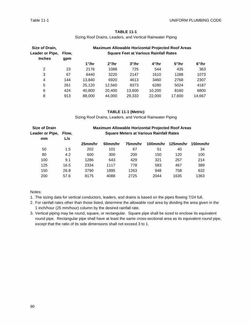
UNIFORM PLUMBING CODE
90
Table 11-1
TABLE 11-1Sizing Roof Drains, Leaders, and Vertical Rainwater Piping
Size of Drain, Maximum Allowable Horizontal Projected Roof AreasLeader or Pipe, Flow, Square Feet at Various Rainfall Rates
Inches gpm1"/hr 2"/hr 3"/hr 4"/hr 5"/hr 6"/hr
2 23 2176 1088 725 544 435 3633 67 6440 3220 2147 1610 1288 10734 144 13,840 6920 4613 3460 2768 23075 261 25,120 12,560 8373 6280 5024 41876 424 40,800 20,400 13,600 10,200 8160 68008 913 88,000 44,000 29,333 22,000 17,600 14,667
TABLE 11-1 (Metric)Sizing Roof Drains, Leaders, and Vertical Rainwater Piping
Size of Drain Maximum Allowable Horizontal Projected Roof AreasLeader or Pipe, Flow, Square Meters at Various Rainfall Rates
mm L/s25mm/hr 50mm/hr 75mm/hr 100mm/hr 125mm/hr 150mm/hr
50 1.5 202 101 67 51 40 3480 4.2 600 300 200 150 120 100100 9.1 1286 643 429 321 257 214125 16.5 2334 1117 778 583 467 389150 26.8 3790 1895 1263 948 758 632200 57.6 8175 4088 2725 2044 1635 1363
Notes:1. The sizing data for vertical conductors, leaders, and drains is based on the pipes flowing 7/24 full.2. For rainfall rates other than those listed, determine the allowable roof area by dividing the area given in the
1 inch/hour (25 mm/hour) column by the desired rainfall rate.3. Vertical piping may be round, square, or rectangular. Square pipe shall be sized to enclose its equivalent
round pipe. Rectangular pipe shall have at least the same cross-sectional area as its equivalent round pipe,except that the ratio of its side dimensions shall not exceed 3 to 1.
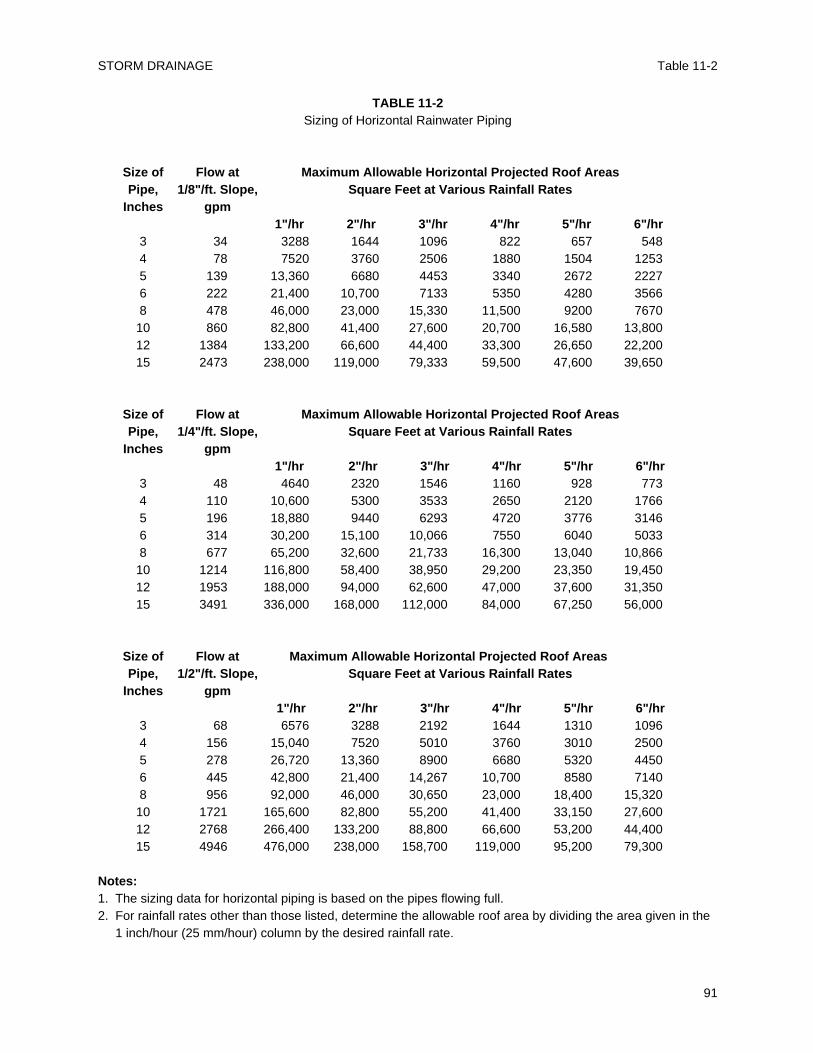
STORM DRAINAGE Table 11-2
91
TABLE 11-2Sizing of Horizontal Rainwater Piping
Size of Flow at Maximum Allowable Horizontal Projected Roof AreasPipe, 1/8"/ft. Slope, Square Feet at Various Rainfall Rates
Inches gpm1"/hr 2"/hr 3"/hr 4"/hr 5"/hr 6"/hr
3 34 3288 1644 1096 822 657 5484 78 7520 3760 2506 1880 1504 12535 139 13,360 6680 4453 3340 2672 22276 222 21,400 10,700 7133 5350 4280 35668 478 46,000 23,000 15,330 11,500 9200 767010 860 82,800 41,400 27,600 20,700 16,580 13,80012 1384 133,200 66,600 44,400 33,300 26,650 22,20015 2473 238,000 119,000 79,333 59,500 47,600 39,650
Size of Flow at Maximum Allowable Horizontal Projected Roof AreasPipe, 1/4"/ft. Slope, Square Feet at Various Rainfall Rates
Inches gpm1"/hr 2"/hr 3"/hr 4"/hr 5"/hr 6"/hr
3 48 4640 2320 1546 1160 928 7734 110 10,600 5300 3533 2650 2120 17665 196 18,880 9440 6293 4720 3776 31466 314 30,200 15,100 10,066 7550 6040 50338 677 65,200 32,600 21,733 16,300 13,040 10,86610 1214 116,800 58,400 38,950 29,200 23,350 19,45012 1953 188,000 94,000 62,600 47,000 37,600 31,35015 3491 336,000 168,000 112,000 84,000 67,250 56,000
Size of Flow at Maximum Allowable Horizontal Projected Roof AreasPipe, 1/2"/ft. Slope, Square Feet at Various Rainfall Rates
Inches gpm1"/hr 2"/hr 3"/hr 4"/hr 5"/hr 6"/hr
3 68 6576 3288 2192 1644 1310 10964 156 15,040 7520 5010 3760 3010 25005 278 26,720 13,360 8900 6680 5320 44506 445 42,800 21,400 14,267 10,700 8580 71408 956 92,000 46,000 30,650 23,000 18,400 15,32010 1721 165,600 82,800 55,200 41,400 33,150 27,60012 2768 266,400 133,200 88,800 66,600 53,200 44,40015 4946 476,000 238,000 158,700 119,000 95,200 79,300
Notes:1. The sizing data for horizontal piping is based on the pipes flowing full.2. For rainfall rates other than those listed, determine the allowable roof area by dividing the area given in the
1 inch/hour (25 mm/hour) column by the desired rainfall rate.
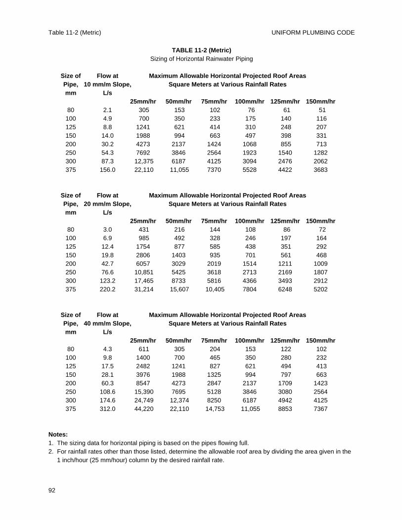
UNIFORM PLUMBING CODE
92
Table 11-2 (Metric)
TABLE 11-2 (Metric)Sizing of Horizontal Rainwater Piping
Size of Flow at Maximum Allowable Horizontal Projected Roof AreasPipe, 10 mm/m Slope, Square Meters at Various Rainfall Ratesmm L/s
25mm/hr 50mm/hr 75mm/hr 100mm/hr 125mm/hr 150mm/hr80 2.1 305 153 102 76 61 51100 4.9 700 350 233 175 140 116125 8.8 1241 621 414 310 248 207150 14.0 1988 994 663 497 398 331200 30.2 4273 2137 1424 1068 855 713250 54.3 7692 3846 2564 1923 1540 1282300 87.3 12,375 6187 4125 3094 2476 2062375 156.0 22,110 11,055 7370 5528 4422 3683
Size of Flow at Maximum Allowable Horizontal Projected Roof AreasPipe, 20 mm/m Slope, Square Meters at Various Rainfall Ratesmm L/s
25mm/hr 50mm/hr 75mm/hr 100mm/hr 125mm/hr 150mm/hr80 3.0 431 216 144 108 86 72100 6.9 985 492 328 246 197 164125 12.4 1754 877 585 438 351 292150 19.8 2806 1403 935 701 561 468200 42.7 6057 3029 2019 1514 1211 1009250 76.6 10,851 5425 3618 2713 2169 1807300 123.2 17,465 8733 5816 4366 3493 2912375 220.2 31,214 15,607 10,405 7804 6248 5202
Size of Flow at Maximum Allowable Horizontal Projected Roof AreasPipe, 40 mm/m Slope, Square Meters at Various Rainfall Ratesmm L/s
25mm/hr 50mm/hr 75mm/hr 100mm/hr 125mm/hr 150mm/hr80 4.3 611 305 204 153 122 102100 9.8 1400 700 465 350 280 232125 17.5 2482 1241 827 621 494 413150 28.1 3976 1988 1325 994 797 663200 60.3 8547 4273 2847 2137 1709 1423250 108.6 15,390 7695 5128 3846 3080 2564300 174.6 24,749 12,374 8250 6187 4942 4125375 312.0 44,220 22,110 14,753 11,055 8853 7367
Notes:1. The sizing data for horizontal piping is based on the pipes flowing full.2. For rainfall rates other than those listed, determine the allowable roof area by dividing the area given in the
1 inch/hour (25 mm/hour) column by the desired rainfall rate.
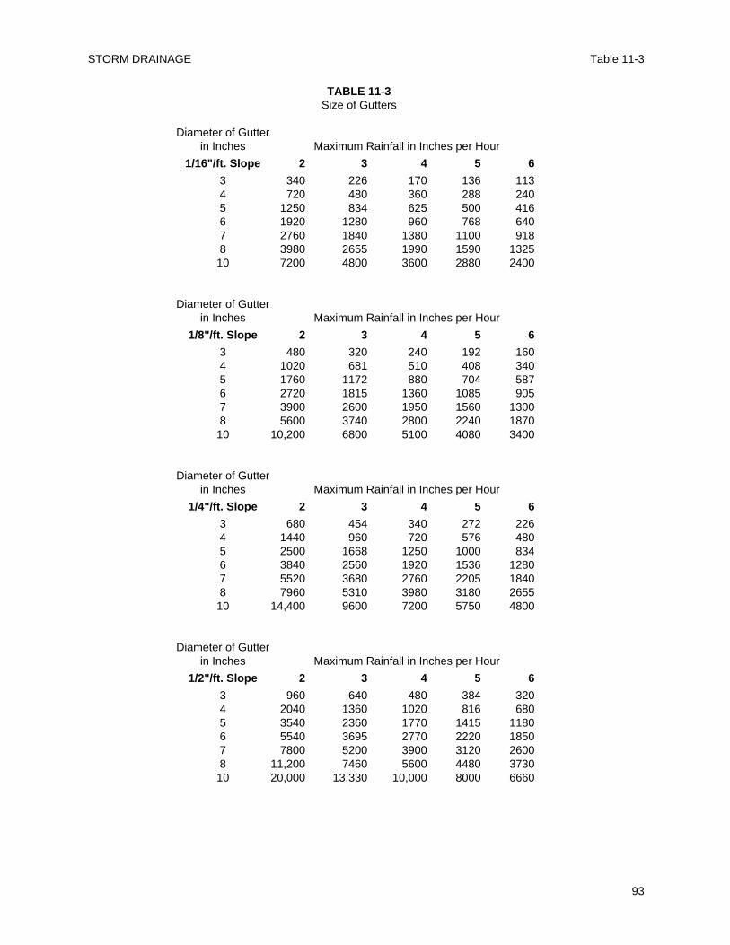
STORM DRAINAGE Table 11-3
93
TABLE 11-3Size of Gutters
Diameter of Gutterin Inches Maximum Rainfall in Inches per Hour
1/16"/ft. Slope 2 3 4 5 6
3 340 226 170 136 1134 720 480 360 288 2405 1250 834 625 500 4166 1920 1280 960 768 6407 2760 1840 1380 1100 9188 3980 2655 1990 1590 1325
10 7200 4800 3600 2880 2400
Diameter of Gutterin Inches Maximum Rainfall in Inches per Hour
1/8"/ft. Slope 2 3 4 5 6
3 480 320 240 192 1604 1020 681 510 408 3405 1760 1172 880 704 5876 2720 1815 1360 1085 9057 3900 2600 1950 1560 13008 5600 3740 2800 2240 1870
10 10,200 6800 5100 4080 3400
Diameter of Gutterin Inches Maximum Rainfall in Inches per Hour
1/4"/ft. Slope 2 3 4 5 6
3 680 454 340 272 2264 1440 960 720 576 4805 2500 1668 1250 1000 8346 3840 2560 1920 1536 12807 5520 3680 2760 2205 18408 7960 5310 3980 3180 2655
10 14,400 9600 7200 5750 4800
Diameter of Gutterin Inches Maximum Rainfall in Inches per Hour
1/2"/ft. Slope 2 3 4 5 6
3 960 640 480 384 3204 2040 1360 1020 816 6805 3540 2360 1770 1415 11806 5540 3695 2770 2220 18507 7800 5200 3900 3120 26008 11,200 7460 5600 4480 3730
10 20,000 13,330 10,000 8000 6660
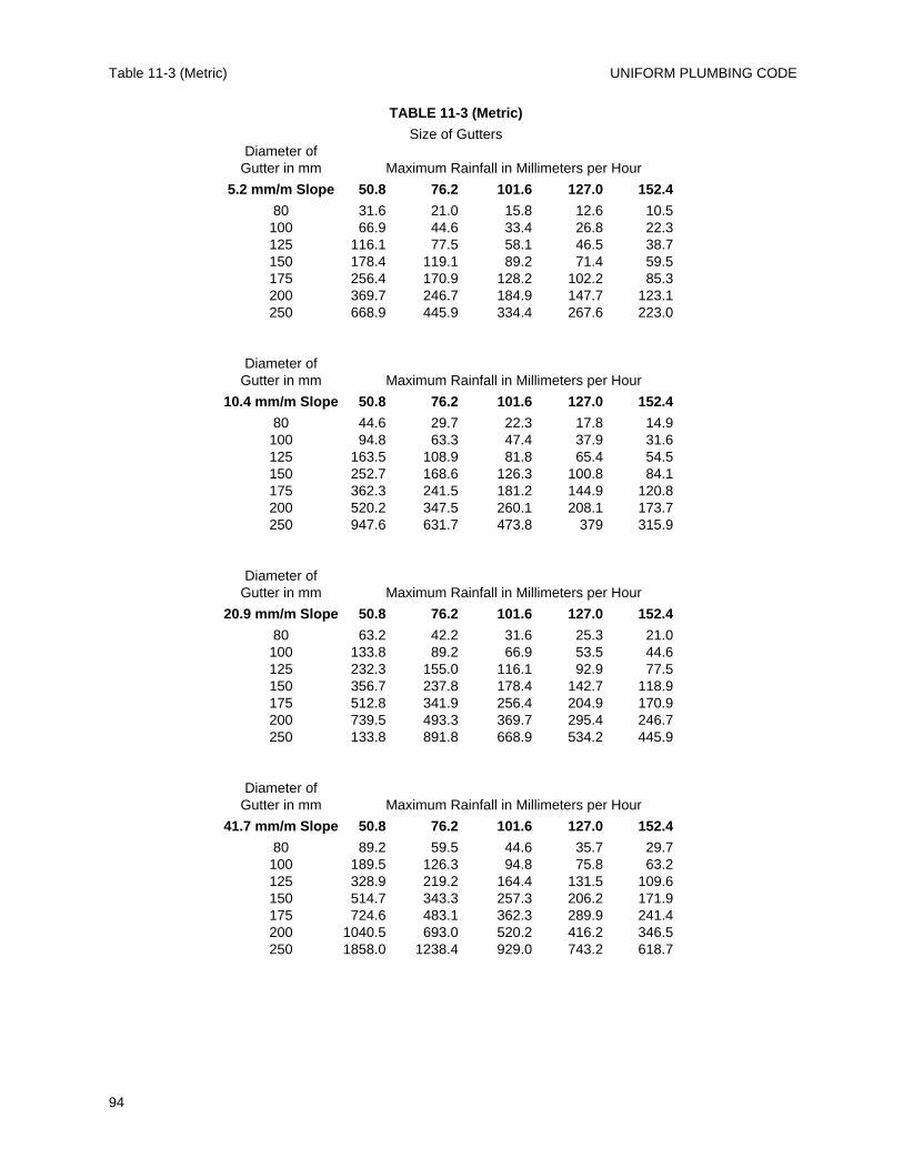
UNIFORM PLUMBING CODE
94
Table 11-3 (Metric)
TABLE 11-3 (Metric)
Size of GuttersDiameter of
Gutter in mm Maximum Rainfall in Millimeters per Hour
5.2 mm/m Slope 50.8 76.2 101.6 127.0 152.4
80 31.6 21.0 15.8 12.6 10.5100 66.9 44.6 33.4 26.8 22.3125 116.1 77.5 58.1 46.5 38.7150 178.4 119.1 89.2 71.4 59.5175 256.4 170.9 128.2 102.2 85.3200 369.7 246.7 184.9 147.7 123.1250 668.9 445.9 334.4 267.6 223.0
Diameter ofGutter in mm Maximum Rainfall in Millimeters per Hour
10.4 mm/m Slope 50.8 76.2 101.6 127.0 152.4
80 44.6 29.7 22.3 17.8 14.9100 94.8 63.3 47.4 37.9 31.6125 163.5 108.9 81.8 65.4 54.5150 252.7 168.6 126.3 100.8 84.1175 362.3 241.5 181.2 144.9 120.8200 520.2 347.5 260.1 208.1 173.7250 947.6 631.7 473.8 379 315.9
Diameter ofGutter in mm Maximum Rainfall in Millimeters per Hour
20.9 mm/m Slope 50.8 76.2 101.6 127.0 152.4
80 63.2 42.2 31.6 25.3 21.0100 133.8 89.2 66.9 53.5 44.6125 232.3 155.0 116.1 92.9 77.5150 356.7 237.8 178.4 142.7 118.9175 512.8 341.9 256.4 204.9 170.9200 739.5 493.3 369.7 295.4 246.7250 133.8 891.8 668.9 534.2 445.9
Diameter ofGutter in mm Maximum Rainfall in Millimeters per Hour
41.7 mm/m Slope 50.8 76.2 101.6 127.0 152.4
80 89.2 59.5 44.6 35.7 29.7100 189.5 126.3 94.8 75.8 63.2125 328.9 219.2 164.4 131.5 109.6150 514.7 343.3 257.3 206.2 171.9175 724.6 483.1 362.3 289.9 241.4200 1040.5 693.0 520.2 416.2 346.5250 1858.0 1238.4 929.0 743.2 618.7
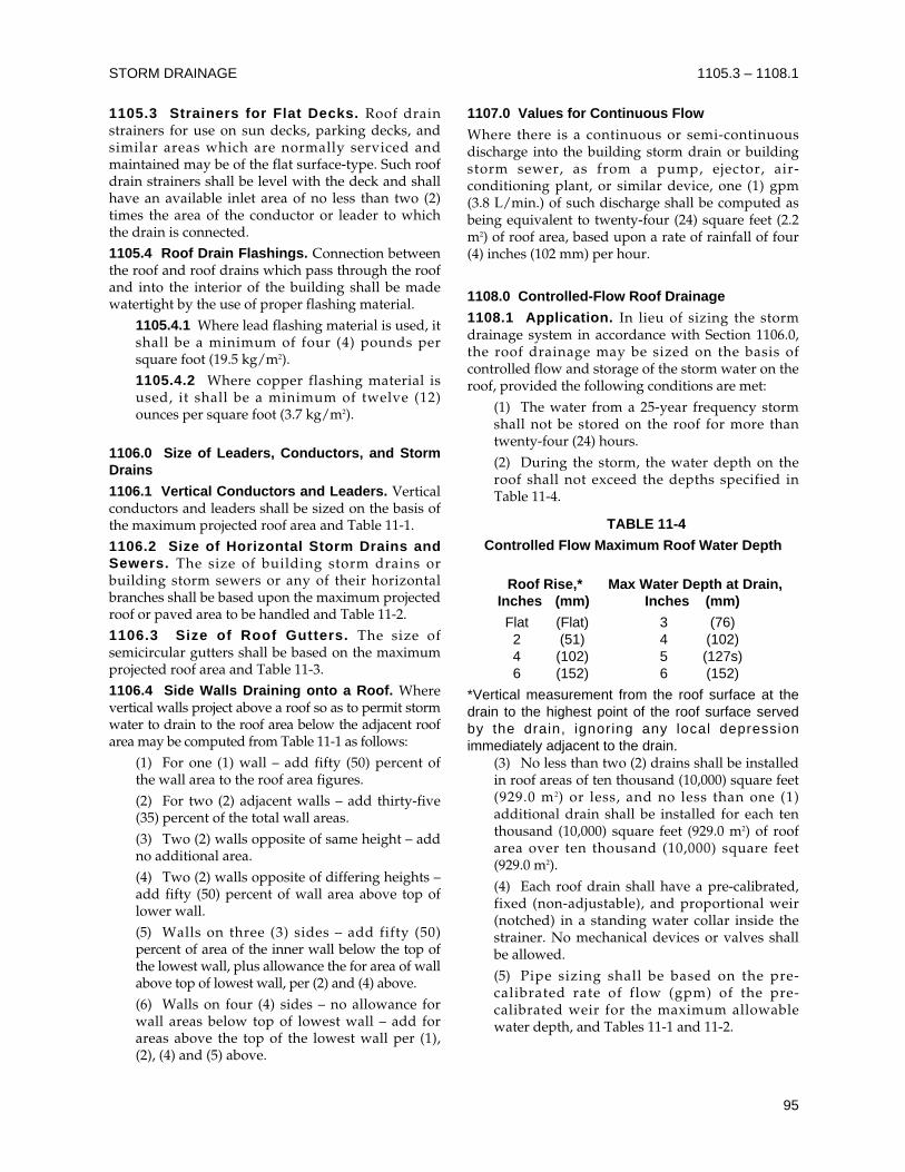
1105.3 Strainers for Flat Decks. Roof drainstrainers for use on sun decks, parking decks, andsimilar areas which are normally serviced andmaintained may be of the flat surface-type. Such roofdrain strainers shall be level with the deck and shallhave an available inlet area of no less than two (2)times the area of the conductor or leader to whichthe drain is connected.1105.4 Roof Drain Flashings. Connection betweenthe roof and roof drains which pass through the roofand into the interior of the building shall be madewatertight by the use of proper flashing material.
1105.4.1 Where lead flashing material is used, itshall be a minimum of four (4) pounds persquare foot (19.5 kg/m2).1105.4.2 Where copper flashing material isused, it shall be a minimum of twelve (12)ounces per square foot (3.7 kg/m2).
1106.0 Size of Leaders, Conductors, and StormDrains
1106.1 Vertical Conductors and Leaders. Verticalconductors and leaders shall be sized on the basis ofthe maximum projected roof area and Table 11-1.1106.2 Size of Horizontal Storm Drains andSewers. The size of building storm drains orbuilding storm sewers or any of their horizontalbranches shall be based upon the maximum projectedroof or paved area to be handled and Table 11-2.1106.3 Size of Roof Gutters. The size ofsemicircular gutters shall be based on the maximumprojected roof area and Table 11-3.1106.4 Side Walls Draining onto a Roof. Wherevertical walls project above a roof so as to permit stormwater to drain to the roof area below the adjacent roofarea may be computed from Table 11-1 as follows:
(1) For one (1) wall – add fifty (50) percent ofthe wall area to the roof area figures.(2) For two (2) adjacent walls – add thirty-five(35) percent of the total wall areas.(3) Two (2) walls opposite of same height – addno additional area.(4) Two (2) walls opposite of differing heights –add fifty (50) percent of wall area above top oflower wall.(5) Walls on three (3) sides – add fifty (50)percent of area of the inner wall below the top ofthe lowest wall, plus allowance the for area of wallabove top of lowest wall, per (2) and (4) above.(6) Walls on four (4) sides – no allowance forwall areas below top of lowest wall – add forareas above the top of the lowest wall per (1),(2), (4) and (5) above.
1107.0 Values for Continuous Flow
Where there is a continuous or semi-continuousdischarge into the building storm drain or buildingstorm sewer, as from a pump, ejector, air-conditioning plant, or similar device, one (1) gpm(3.8 L/min.) of such discharge shall be computed asbeing equivalent to twenty-four (24) square feet (2.2m2) of roof area, based upon a rate of rainfall of four(4) inches (102 mm) per hour.
1108.0 Controlled-Flow Roof Drainage
1108.1 Application. In lieu of sizing the stormdrainage system in accordance with Section 1106.0,the roof drainage may be sized on the basis ofcontrolled flow and storage of the storm water on theroof, provided the following conditions are met:
(1) The water from a 25-year frequency stormshall not be stored on the roof for more thantwenty-four (24) hours.
(2) During the storm, the water depth on theroof shall not exceed the depths specified inTable 11-4.
TABLE 11-4
Controlled Flow Maximum Roof Water Depth
Roof Rise,* Max Water Depth at Drain, Inches (mm) Inches (mm)
Flat (Flat) 3 (76)2 (51) 4 (102)4 (102) 5 (127s)6 (152) 6 (152)
*Vertical measurement from the roof surface at thedrain to the highest point of the roof surface servedby the drain, ignoring any local depressionimmediately adjacent to the drain.
(3) No less than two (2) drains shall be installedin roof areas of ten thousand (10,000) square feet(929.0 m2) or less, and no less than one (1)additional drain shall be installed for each tenthousand (10,000) square feet (929.0 m2) of roofarea over ten thousand (10,000) square feet(929.0 m2).
(4) Each roof drain shall have a pre-calibrated,fixed (non-adjustable), and proportional weir(notched) in a standing water collar inside thestrainer. No mechanical devices or valves shallbe allowed.
(5) Pipe sizing shall be based on the pre-calibrated rate of flow (gpm) of the pre-calibrated weir for the maximum allowablewater depth, and Tables 11-1 and 11-2.
STORM DRAINAGE 1105.3 – 1108.1
95
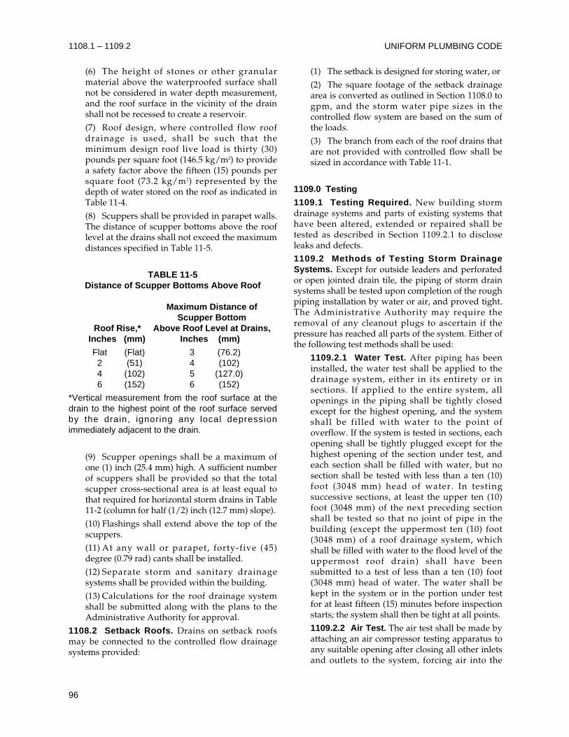
(6) The height of stones or other granularmaterial above the waterproofed surface shallnot be considered in water depth measurement,and the roof surface in the vicinity of the drainshall not be recessed to create a reservoir.
(7) Roof design, where controlled flow roofdrainage is used, shall be such that theminimum design roof live load is thirty (30)pounds per square foot (146.5 kg/m2) to providea safety factor above the fifteen (15) pounds persquare foot (73.2 kg/m2) represented by thedepth of water stored on the roof as indicated inTable 11-4.
(8) Scuppers shall be provided in parapet walls.The distance of scupper bottoms above the rooflevel at the drains shall not exceed the maximumdistances specified in Table 11-5.
TABLE 11-5Distance of Scupper Bottoms Above Roof
Maximum Distance ofScupper Bottom
Roof Rise,* Above Roof Level at Drains,Inches (mm) Inches (mm)
Flat (Flat) 3 (76.2)2 (51) 4 (102)4 (102) 5 (127.0)6 (152) 6 (152)
*Vertical measurement from the roof surface at thedrain to the highest point of the roof surface servedby the drain, ignoring any local depressionimmediately adjacent to the drain.
(9) Scupper openings shall be a maximum ofone (1) inch (25.4 mm) high. A sufficient numberof scuppers shall be provided so that the totalscupper cross-sectional area is at least equal tothat required for horizontal storm drains in Table11-2 (column for half (1/2) inch (12.7 mm) slope).
(10) Flashings shall extend above the top of thescuppers.
(11) At any wall or parapet, forty-five (45)degree (0.79 rad) cants shall be installed.
(12) Separate storm and sanitary drainagesystems shall be provided within the building.
(13) Calculations for the roof drainage systemshall be submitted along with the plans to theAdministrative Authority for approval.
1108.2 Setback Roofs. Drains on setback roofsmay be connected to the controlled flow drainagesystems provided:
(1) The setback is designed for storing water, or
(2) The square footage of the setback drainagearea is converted as outlined in Section 1108.0 togpm, and the storm water pipe sizes in thecontrolled flow system are based on the sum ofthe loads.
(3) The branch from each of the roof drains thatare not provided with controlled flow shall besized in accordance with Table 11-1.
1109.0 Testing
1109.1 Testing Required. New building stormdrainage systems and parts of existing systems thathave been altered, extended or repaired shall betested as described in Section 1109.2.1 to discloseleaks and defects.
1109.2 Methods of Testing Storm DrainageSystems. Except for outside leaders and perforatedor open jointed drain tile, the piping of storm drainsystems shall be tested upon completion of the roughpiping installation by water or air, and proved tight.The Administrative Authority may require theremoval of any cleanout plugs to ascertain if thepressure has reached all parts of the system. Either ofthe following test methods shall be used:
1109.2.1 Water Test. After piping has beeninstalled, the water test shall be applied to thedrainage system, either in its entirety or insections. If applied to the entire system, allopenings in the piping shall be tightly closedexcept for the highest opening, and the systemshall be filled with water to the point ofoverflow. If the system is tested in sections, eachopening shall be tightly plugged except for thehighest opening of the section under test, andeach section shall be filled with water, but nosection shall be tested with less than a ten (10)foot (3048 mm) head of water. In testingsuccessive sections, at least the upper ten (10)foot (3048 mm) of the next preceding sectionshall be tested so that no joint of pipe in thebuilding (except the uppermost ten (10) foot(3048 mm) of a roof drainage system, whichshall be filled with water to the flood level of theuppermost roof drain) shall have beensubmitted to a test of less than a ten (10) foot(3048 mm) head of water. The water shall bekept in the system or in the portion under testfor at least fifteen (15) minutes before inspectionstarts; the system shall then be tight at all points.
1109.2.2 Air Test. The air test shall be made byattaching an air compressor testing apparatus toany suitable opening after closing all other inletsand outlets to the system, forcing air into the
UNIFORM PLUMBING CODE
96
1108.1 – 1109.2
system until there is a uniform gage pressure offive (5) psi (34.5 kPa) or sufficient to balance acolumn of mercury ten (10) inches (254 mm) inheight. This pressure shall be held withoutintroduction of additional air for a period of atleast fifteen (15) minutes. Schedule 40 plasticDWV systems shall not be tested by the air testmethod.
1109.2.3 Exceptions. When circumstancesexist that make air and water tests, described inSections 1109.2.1 and 1109.2.2 above, impractical,and for minor maintenance, repairs andinstallations, the Administrative Authority mayperform the inspection as considered advisableby said authority to assure that the work hasbeen in accordance with provisions of this Code.
STORM DRAINAGE 1109.2
97

UNIFORM PLUMBING CODE
98
1201.0 General
The regulations of this chapter shall govern theinstallation of all fuel gas piping in or in connectionwith any building or structure or within the propertylines of any premises, other than service pipe.
1202.0 Definitions
For the purposes of this Code, certain terms, phrases,words, and their derivatives shall be interpreted asset forth in this section, provided, however, thatwhenever the words “gas meters” appear, they shallbe construed to also mean valves and those devicesrequired for the regulation of pressure and themeasurement of natural gas being dispensed for anybuilding, structure, or premises.
1202.1 Appliance Fuel Connector – An assembly oflisted semi-rigid or flexible tubing and fittings tocarry fuel between a fuel piping outlet and a fuelburning appliance.
1202.2 Approved – As to materials, workmanship,and types of construction, means approved by theAdministrative Authority as the result ofinvestigation, inspection, or test conducted by themor by reason of accepted principles or tests by otherrecognized testing agency or authority.
1202.3 Fuel Gas – Natural, manufactured, liquifiedpetroleum, or a mixture of these.
1202.4 Gas Piping – Any installation of pipe,valves, or fittings that is used to convey fuel gas,installed on any premises or in any building, butshall not include:
(1) Any portion of the service piping.
(2) Any approved piping connection six (6) feet(1829 mm) or less in length between an existinggas outlet and a gas appliance in the same roomwith the outlet.
1202.5 Gas Piping System – Any arrangement ofgas piping supplied by one (1) meter and eacharrangement of gas piping serving a building,structure, or premises, whether individually meteredor not.
1202.6 RESERVED
1202.7 Liquified Petroleum Gas (LPG) Facilities –Liquified petroleum gas (LPG) facilities means tanks,containers, container valves, regulating equipment,meters, and/or appurtenances for the storage andsupply of liquified petroleum gas for any building,structure or premises.
1202.8 Quick-Disconnect Device – A hand-operated device which provides a means forconnecting and disconnecting an appliance or anappliance connector to a gas supply and which isequipped with an automatic means to shut off thegas supply when the device is disconnected.
1202.9 Service Piping – The piping and equipmentbetween the street gas main and the gas pipingsystem inlet, which is installed by and is under thecontrol and maintenance of the serving gas supplier.
1202.10 Transition Gas Riser – Any listed orapproved section or sections of pipe and fittingsused to convey fuel gas and installed in a gas pipingsystem for the purpose of providing a transitionfrom below ground to above ground.
1203.0 Workmanship
No gas piping shall be strained or bent and noappliance shall be supported by or develop anystrain or stress on its supply piping. Gas pipingsupplying appliances designed to be supported bythe piping may be used to support such appliances,when first approved by the AdministrativeAuthority.
1204.0 Inspection
1204.1 Upon completion of the installation,alteration, or repair of any gas piping, and prior tothe use thereof, the Administrative Authority shallbe notified that such gas piping is ready forinspection.
1204.2 All excavations required for the installationof underground piping shall be kept open until suchtime as the piping has been inspected and approved.If any such piping is covered or concealed beforesuch approval, it shall be exposed upon the directionof the Administrative Authority.
1204.3 The Administrative Authority shall make thefollowing inspections and shall either approve thatportion of the work as completed, or shall notify thepermit holder wherein the same fails to comply withthis Code.
1204.3.1 Rough Piping Inspection
This inspection shall be made after all gas pipingauthorized by the permit has been installed, andbefore any such piping has been covered orconcealed, or any fixture or appliance has beenattached thereto. This inspection shall include a
99
CHAPTER 12
FUEL PIPING
determination that the gas piping size, material,and installation meet the requirements of thisCode.
1204.3.2 Final Piping Inspection
This inspection shall be made after all pipingauthorized by the permit has been installed andafter all portions thereof which are to be coveredor concealed are so concealed and before anyfixtures, appliance, or shutoff valve has beenattached thereto. This inspection shall include anair, CO2 or nitrogen pressure test, at which timethe gas piping shall stand a pressure of not lessthan ten (10) pounds per square inch (68.9 kPa)gauge pressure, or at the discretion of theAdministrative Authority, the piping and valvesmay be tested at a pressure of at least six (6)inches (152 mm) of mercury, measured with amanometer or slope gauge. Test pressures shallbe held for a length of time satisfactory to theAdministrative Authority, but in no case for lessthan fifteen (15) minutes, with no perceptibledrop in pressure. For welded piping, and forpiping carrying gas at pressures in excess offourteen (14) inches (356 mm) water columnpressure, the test pressure shall not be less thansixty (60) pounds per square inch (413.4 kPa)and shall be continued for a length of timesatisfactory to the Administrative Authority, butin no case for less than thirty (30) minutes. Thesetests shall be made using air, CO2, or nitrogenpressure only and shall be made in the presenceof the Administrative Authority. All necessaryapparatus for conducting tests shall be furnishedby the permit holder. Test gauges used inconducting tests shall comply with Section 319.0,Test Gauges.
1204.4 In cases where the work authorized by thepermit consists of a minor installation of additionalpiping to piping already connected to a gas meter,the foregoing inspections may be waived at thediscretion of the Administrative Authority. In thisevent, the Administrative Authority shall make suchinspection as deemed advisable in order to beassured that the work has been performed inaccordance with the intent of this Code.
1205.0 Certificate of Inspection
1205.1 If, upon final piping inspection, theinstallation is found to comply with the provisions ofthis Code, a certificate of inspection may be issuedby the Administrative Authority.
1205.2 A copy of the certificate of such final pipinginspection shall be issued to the serving gas suppliersupplying gas to the premises.
1205.3 It shall be unlawful for any serving gassupplier, or person furnishing gas, to turn on, orcause to be turned on, any fuel gas or any gas meteror meters, until such certificate of final inspection, asherein provided, has been issued.
1206.0 Authority to Render Gas Service
1206.1 It shall be unlawful for any person, firm, orcorporation, excepting an authorized agent oremployee of a person, firm, or corporation engagedin the business of furnishing or supplying gas andwhose service pipes supply or connect with theparticular premises, to turn on or reconnect gasservice in or on any premises where and when gasservice is, at the time, not being rendered.
1206.2 It shall be unlawful to turn on or connect gasin or on any premises unless all outlets are properlyand securely connected to gas appliances or cappedor plugged with screw joint fittings.
1207.0 Authority to Disconnect
1207.1 The Administrative Authority or the servinggas supplier is hereby authorized to disconnect anygas piping or appliance, or both, which shall befound not to conform to the requirements of thisCode or which may be found defective and in suchcondition as to endanger life or property.
1207.2 Where such disconnection has been made, anotice shall be attached to such gas piping orappliance, or both, which shall state the same hasbeen disconnected, together with the reasonstherefor.
1207.3 It shall be unlawful to remove or disconnectany gas piping or gas appliance without capping orplugging with a screw joint fitting the outlet fromwhich said pipe or appliance was removed. Alloutlets to which gas appliances are not connectedshall be left capped gastight on any piping systemwhich has been installed, altered, or repaired.
Exception: When an approved listed quick-disconnect device is used.
1208.0 Temporary Use of Gas
Where temporary use of gas is desired and theAdministrative Authority deems the use necessary, apermit may be issued for such use for a period oftime not to exceed that designated by theAdministrative Authority, provided that such gaspiping system otherwise conforms to therequirements of this Code regarding material, sizing,and safety.
UNIFORM PLUMBING CODE1204.3 – 1208.0
100
1209.0 Gas Meter Locations
1209.1 All gas meter locations shall be approved bythe Administrative Authority and the serving gassupplier.
1209.2 Where more than one (1) meter is set on aparticular premises, they shall all be set at one (1)location, except where this is impractical. In multiplemeter installations, each separate gas piping systemshall be identified by the permittee in a mannersatisfactory to the serving gas supplier serving thegas.
1209.3 All gas meters shall be preceded by a mainsupply shutoff valve and shall be so placed as to beat all times readily accessible for inspection, reading,testing, and shutting off the gas supply. All servicepiping or main supply shutoff valves must beoutside of the building and readily accessible.
1209.4 In order that gas may be supplied, the gaspiping inlet shall be located with respect to theproposed meter location, in accordance with thelocal serving gas supplier instructions.
1209.5 Access to enclosed gas meters, except thoselocated in an approved vault supplied by the servinggas supplier, shall be through an opening or doornot less in size than twenty-two (22) inches (559 mm)by twenty-four (24) inches (610 mm), but in no event,smaller than that specified by the local serving gassupplier.
1209.6 Gas meters shall not be located under ashow window or under interior stairways or inengine, boiler, heater, or electric meter rooms. Wherenot prohibited by other regulation, gas meters maybe located in the open under exterior stairways.
1210.0 Material for Gas Piping
1210.1 All piping used for the installation,extension, alteration, or repair of any gas piping shallbe standard weight wrought iron or steel(galvanized or black), yellow brass (containing notmore than seventy-five (75) percent copper), orcopper tube or Types K, L or ACR. Approved PEpipe may be used in exterior buried piping systems.
1210.1.1 Copper alloy tubing shall not be usedif the gas contains more than an average of 0.3grains of hydrogen sulfide per 100 standardcubic feet of gas (0.7 milligrams per 100 liters).
1210.2 All such pipe shall be either new, or shallpreviously have been used for no other purpose thanconveying gas; it shall be in good condition and freefrom internal obstructions. Burred ends shall bereamed to the full bore of the pipe.
1210.3 All fittings used in connection with theabove piping shall be of malleable iron, yellow brass
(containing not more than seventy-five (75) percentcopper), or approved plastic fittings.
1210.4 All valves and appurtenances used inconnection with the above piping shall be of a typedesigned and approved for use with fuel gas.
1210.5 Valves up to and including two (2) inches(50 mm) shall be brass or other approved material.
1211.0 Installation of Gas Piping
1211.1 All joints in the piping system, unlesswelded, brazed or flared, shall be screwed joints,having approved standard threads. Such screwedjoints shall be made up with approved pipe jointmaterial, insoluble in the presence of fuel gas andapplied to the male threads only.
1211.2 All copper tubing joints shall be brazed,flared or screwed joints.
1211.2.1 Brazed joints shall be made bycertified brazers in accordance with theapplicable standard(s) in Table 14-1 and withapproved material having a melting point notless than 1000°F (538°C) and containing notmore than 0.05 percent phosphorus.
1211.2.2 Flared joints shall be made withapproved gas tubing fittings and shall not beused in concealed or inaccessible locations.
1211.3 All welded joints in the piping system shallbe welded by a certified pipe welder as defined inChapter 2 (see Welder, Pipe).
1211.4 No gas piping shall be installed in or on theground under any building or structure unlessinstalled in gastight conduit, and all exposed gaspiping shall be kept at least six (6) inches (152 mm)above grade or structure. The term "building orstructure" shall include structures such as porchesand steps, whether covered or uncovered,breezeways, roofed porte-cocheres, roofed patios,carports, covered walks, covered driveways, andsimilar structures or appurtenances.
The conduit shall be of material approved forinstallation underground beneath buildings and notless than Schedule 40 pipe. The interior diameter ofthe conduit shall be not less than one-half (1/2) inch(15 mm) larger than the outside diameter of the gaspiping.
The conduit shall extend to a point at least(12) inches (305 mm) beyond any area where it isrequired to be installed or to the outside wall of abuilding, and the outer ends shall not be sealed.Where the conduit terminates within a building, itshall be readily accessible and the space betweenthe conduit and the gas piping shall be sealed toprevent leakage of gas into the building.
1209.0 – 1211.4FUEL PIPING
101
Concealed unprotected gas piping may beinstalled above grade in approved recesses or channels.
Exception: When necessary due to structuralconditions, approved type gas piping may beinstalled in other locations, when permission hasfirst been obtained from the AdministrativeAuthority.
1211.5 Where water vapor is present in the fuel gasserved, accessible drip pipes shall be provided atpoints where condensation will tend to collect.1211.6 Ferrous gas piping installed underground inexterior locations shall be protected from corrosionby approved coatings or wrapping materials or byany other approved manner. All horizontal metallicpiping shall have at least twelve (12) inches (305 mm) of earth cover or other equivalent protection.Plastic gas piping shall have at least eighteen (18)inches (457 mm) of earth cover or other equivalentprotection. Risers, including prefabricated risersinserted with plastic pipe, shall be metallic and shallbe wrapped or coated to a point at least six (6) inches(152 mm) above grade or protected in an approvedmanner. When a riser connects underground toplastic pipe, the underground horizontal metallicportion of the riser shall extend at least thirty (30)inches (762 mm) before connecting to the plastic pipeby means of an approved transition fitting or adapter.
Exception: Listed one-piece ninety (90) degree(1.6 rad) transition fittings or risers may haveless than thirty (30) inches (762 mm) ofhorizontal metallic piping.
1211.7 Underground ferrous gas piping shall beelectrically isolated from the rest of the gas systemwith listed or approved isolation fittings installed aminimum of six (6) inches (152 mm) above grade.1211.8 Copper tubing systems shall be identifiedwith an appropriate label, with black letters on ayellow field, to indicate the piping system conveysfuel gas. These labels shall be permanently affixed tothe tubing within one (1) foot (304.8 mm) of thepenetration of a wall, floor or partition and atmaximum six-foot intervals throughout the length ofthe tubing runs. Labels shall be located to be visibleto facilitate inspection.1211.9 Copper tubing systems shall be supportedand protected as follows:
1211.9.1 Copper tubing running parallel tojoists shall be fastened to the center of the joist ata maximum of (six)-6 foot (1829 mm) intervals.1211.9.2 Copper tubing running at an angle tojoists shall be installed either through holes in thejoists that are at least 1-1/2 times the outsidediameter of the tubing or fastened to andsupported at a maximum of (six)-6 foot (1829 mm)intervals.
1211.9.3 Copper tubing running through holesin joists that are closer than one and threequarter (1-3/4) inches (44 mm) to the exposedface of the joist shall be protected with a steelstriker plate at least 0.0508-inch (16 gauge) thick.
1211.9.4 Copper tubing running verticallythrough partition walls shall not be supportedwithin the wall space, except at the floor orceiling. Steel striker plates or steel pipe of at least0.0508 inch (16 gauge) thick and extending aminimum of 4 inches beyond concealedpenetrations of floor/ceiling plates, wall studs,fire stops, etc. shall be installed between thetubing and the finished wall.
1211.10 All gas pipe protective coatings shall beapproved types, machine applied, and conform torecognized standards. Field wrapping shall provideequivalent protection and is restricted to thosefittings and short sections where the factory wraphas been damaged or necessarily stripped forthreading or welding (see Appendix I, IS-13). Zinccoatings (galvanizing) shall not be deemed adequateprotection for gas piping below ground. Ferrousmetals in exposed exterior locations shall beprotected from corrosion in a manner satisfactory tothe Administrative Authority.
Protectively coated pipe shall be inspected andtested and any visible void, damage or imperfectionto the pipe coating shall be repaired to comply withSection 313.0 (see Appendix I, IS-13).
1211.11 All gas piping shall be adequatelysupported by metal straps or hooks at intervals notto exceed those shown in Table 12-2. Gas pipinginstalled below grade shall be effectively supportedat all points on undisturbed or well compacted soilor sand.
1211.12 Gas piping supplying more than one (1)building on any one (1) premises shall be equippedwith separate shutoff valves to each building, soarranged that the gas supply can be turned on or offto any individual or separate building. Such shutoffvalve shall be located outside the building it suppliesand shall be readily accessible at all times. Buildingsaccessory to single family residences are exemptfrom the requirements of this subsection.
1211.13 Where unions are necessary, right and leftnipples and couplings shall be used. Ground-jointunions may be used at exposed fixture, appliance, orequipment connections and in exposed exteriorlocations immediately on the discharge side of abuilding shutoff valve. Heavy duty flanged typeunions may be used in special cases, when firstapproved by the Administrative Authority. Bushingsshall not be used in concealed locations.
UNIFORM PLUMBING CODE1211.4 – 1211.13
102
1211.14 When air, oxygen, or other specialsupplementary gas under pressure is introducedwith the regularly supplied gas, either directly intothe gas piping system or at burners, a deviceapproved by the Administrative Authority and theserving gas supplier shall be installed to preventbackflow of such special gas into the gas pipingsystem or serving gas supplier's meter. This deviceshall be located between the source of the special gasand the serving gas supplier's meter and shall be onthe gas line leading to the appliance using the specialgas. This device may be either a spring loaded ordiaphragm type check valve and shall be capable ofwithstanding any pressure which may be imposedon it.
1211.15 When liquified petroleum or other standbygas is interconnected with the regular gas pipingsystem, an approved three-way two-port valve orother adequate safeguard acceptable to theAdministrative Authority and the serving gassupplier shall be installed to prevent backflow intoeither supply system.
1211.16 Valves used in connection with gas pipingshall be approved types and shall be accessible.
1211.17 All gas outlets located in a barbecue orfireplace shall be controlled by an approvedoperating valve located in the same room andoutside the hearth, but not more than four (4) feet(1219 mm) from such outlets. When piping on thedischarge side of any such control valve is standardweight brass or galvanized steel, such piping may beembedded in or surrounded by not less than two (2)inches (51 mm) of concrete or masonry.
1211.18 An accessible shutoff valve of a type setforth in Section 1211.16, shall be installed in the fuelsupply piping outside of each appliance and aheadof the union connection thereto, and in addition toany valve on the appliance. Shutoff valves shall bewithin three (3) feet (914 mm) of the appliance itserves, and in the same room or space where theappliance is located.
Shutoff valves may be located immediatelyadjacent to and inside or under an appliance whenplaced in an accessible and protected location andwhen such appliance may be removed withoutremoval of the valve.
Shutoff valves may be accessibly located insidewall heaters and wall furnaces listed for recessedinstallation where necessary maintenance can beperformed without removal of the shutoff valve.
1211.19 An electrically continuous insulatednumber 18 AWG yellow 0.040 inch (1 mm) diametercopper tracer wire or other approved materials shallbe installed with and attached to underground non-
metallic gas piping and shall terminate above gradeat each end.
1211.20 Changes in direction of gas piping shall bemade by appropriate use of fittings, except PE gaspipe and tubing may be bent to a radius of not lessthan twenty (20) times the nominal pipe or tubingdiameter.
1212.0 Appliance Connectors
Appliance connections shall, at no time, have adiameter less than that of the inlet connection to theappliance as provided by the manufacturer and eachappliance shall be rigidly connected to the gas pipingwith materials as provided in Section 1210.0.
Exception: A gas appliance may be connectedwith an approved listed metal applianceconnector under the following conditions:
(1) Listed metal appliance connectors shall havean overall length of not to exceed three (3) feet(914 mm) except a range or dryer connector,which may not exceed six (6) feet (1829 mm).
(2) No part of such connector shall be concealedwithin or extended through any wall, floor,partition, or appliance housing.
(3) A listed accessible appliance connectorvalve not less than the nominal size of theconnector shall be provided at the gas pipingoutlet immediately ahead of the connector
(4) All connectors shall be of such size as toprovide the total demand of the connectedappliance based on the applicable Tables 12-9 or12-10.
(5) Aluminum alloy connectors may be usedonly in interior locations where they shall not bein contact with masonry, plaster, or insulation orare not subject to repeated corrosive wettings.
(6) The connection of an indoor appliance withany type of gas hose is prohibited, except whenused with laboratory or shop equipment orequipment that requires mobility duringoperation. Such connections shall have the shut-off or stopcock installed at the connection to thebuilding piping. When gas hose is used, it shall beof the minimum practical length, but not to exceedsix (6) feet (1829 mm), except for hand torches andspecial mobile equipment, and shall not extendfrom one room to another nor pass through anywalls, partitions, ceilings, or floors. Under nocircumstances shall gas hose be concealed fromview or used in a concealed location. Only listedgas hose shall be used and only in accordancewith its listing. Gas hose shall not be used where itis likely to be subjected to excessive temperatures
1211.14 – 1212.0FUEL PIPING
103
(above 125°F [51.7°C]) nor shall it be used as asubstitute for a standard appliance connector.
(7) Outdoor portable appliances may beconnected with an approved outdoor hoseconnector not to exceed fifteen (15) feet (4572mm) in length provided it connects outdoors toapproved gas piping including an approvedvalve at the inlet of the hose connector.
(8) Appliances may be connected to the fuel gaspiping by means of an approved listed quick-disconnect device.
1213.0 Liquified Petroleum Gas Facilities andPiping
In addition to the requirements of this Code for gaspiping, the facilities and piping for use with liquifiedpetroleum gas shall meet the following requirements:
1213.1 All liquified petroleum gas facilities shallconform to approved standards (see Table 14-1). Allsuch facilities and their locations shall be acceptableto the Administrative Authority and shall conform tostate and local fire prevention regulations.
1213.2 Where liquified petroleum gas facilitiesserve more than one (1) customer through separatepiping systems, each system shall be identified in amanner satisfactory to the Administrative Authorityand the gas supplier.
1213.3 All liquified petroleum gas facilities shall beso placed as to be at all times readily accessible forinspection, reading, testing, and shutting off the gassupply. All service piping and main supply shutoffvalves shall be outside of the building. All mainsupply valves shall be of approved type and readilyaccessible.
1213.4 In order that gas may be supplied, the gaspiping inlet shall be located with respect to theproposed liquified petroleum gas facility location inaccordance with the requirements of this section andthe supplier's instructions.
1213.5 Liquified petroleum gas facilities shall not belocated in any pit or basement, under show windowsor interior stairways, in engine, boiler, heater, orelectric meter rooms. When not prohibited byanother regulation, approved liquified petroleumgas metering devices may be located in the openunder exterior stairways.
1213.6 Liquified petroleum gas piping shall notserve any gas water heater located in a pit orbasement where heavier than air gas might collect toform a flammable mixture.
1213.7 Pipe joint compounds used on threadconnections shall be insoluble in liquified petroleumgas.
1213.8 Every valve and appurtenance used on suchpiping shall be designed and approved for use withliquified petroleum gas.
1213.9 Discharge from relief valves shall be intoopen air and shall not be less than five (5) feet (1524mm) horizontally away from any opening into abuilding which is below such discharge.
1214.0 Leaks
1214.1 Leaks in gas piping shall be located byapplying soapy water to the exterior of the piping.
1214.2 Fire or acid shall not be used to locate orrepair leaks, nor shall any substance other than air,carbon dioxide or nitrogen be introduced into thegas piping.
1214.3 It shall not be permissible to repair defects ingas piping or fittings, but upon having been located,the defective pipe or fitting shall be removed andreplaced with sound material.
1215.0 Interconnections of Gas Piping Systems
1215.1 It shall be unlawful to connect any gasappliance in such a manner that such appliance mayreceive gas from more than one (1) system of gaspiping.
1215.2 The installation, use, or maintenance of a gasvalve which makes it possible to turn on, control, orotherwise direct the flow of gas from one (1) systemof gas piping to another, where such systems aresupplied with gas from separate meters, is herebyprohibited, and any such valves or otherinterconnection between separate systems of gaspiping shall be removed upon order of theAdministrative Authority.
1216.0 Required Gas Supply
1216.1 The following regulations, as set forth in thissection and in Section 1217.0, Required Gas PipingSize, shall be the standard for the installation of gaspiping. All natural gas regulations and tables arebased on the use of gas having a specific gravity ofsixty hundredths (0.60), supplied at six (6) to eight(8) inches (152–203 mm) water column pressure atthe outlet of the meter. For undiluted liquifiedpetroleum gas, gas piping may be sized for 2500 Btuper cubic foot (25.9 Watt-hours/L) at eleven (11)inches (279 mm) water column and specific gravityof one and fifty-two hundredths (1.52).
Note: Where gas of a different specific gravity isto be delivered, the serving gas supplier shouldbe contacted for specific gravity conversionfactors to use in sizing piping systems from thepipe sizing tables in this chapter.
UNIFORM PLUMBING CODE1212.0 – 1216.1
104
1216.2 The hourly volume of gas required at eachpiping outlet shall be taken as not less than themaximum hourly rating as specified by themanufacturer of the appliance or appliances to beconnected to each such outlet.1216.3 Where the gas appliances to be installedhave not been definitely specified, Table 12-1 may beused as a reference to estimate requirements oftypical appliances.
To obtain the cubic feet per hour (L/sec.) of gasrequired, divide input of appliances by the averageBtu (W) heating value per cubic foot (L) of the gas.The average Btu (W) per cubic foot (L) of the gas inthe area of the installation may be obtained from theserving gas supplier.1216.4 The size of the supply piping outlet for anygas appliance shall not be less than one-half (1/2)inch (15 mm).
The minimum size of any piping outlet for a mobilehome shall be three-quarter (3/4) inch (20 mm).
1217.0 Required Gas Piping Size
1217.1 Where the maximum demand does notexceed two hundred fifty (250) cubic feet per hour (2L/sec.) and the maximum length of piping betweenthe meter and the most distant outlet is not over twohundred fifty (250) feet (76200 mm), the size of eachsection and each outlet of any system of gas pipingshall be determined by means of Table 12-3, or Table12-11 for copper tubing systems. Other systemswithin the range of Table 12-3 or 12-11 may be sizedfrom that table or by means of the methods set forthin Section 1217.3.
1217.2 To determine the size of each section of pipein any system within the range of Table 12-3,proceed as follows:
(1) Measure the length of the pipe from the gasmeter location to the most remote outlet on thesystem.
(2) In Table 12-3 select the column showing thatdistance, or the next longer distance if the tabledoes not give the exact length.
(3) Starting at the most remote outlet, find inthe vertical column just selected the gas demandfor that outlet. If the exact figure of demand isnot shown, choose the next larger figure belowin the column.
(4) Opposite this demand figure, in the firstcolumn at the left in Table 12-3 will be found thecorrect size of pipe.
(5) Using this same vertical column, proceed ina similar manner for each section of pipe servingthis outlet. For each section of pipe, determine
the total gas demand supplied by that section.Where gas piping sections serve both heatingand cooling equipment and the installationprevents both units from operatingsimultaneously, only the larger of the twodemand loads need be used in sizing thesesections.
(6) Size each section of branch piping notpreviously sized by measuring the distance fromthe gas meter location to the most remote outletin that branch and follow the procedures ofsteps 2, 3, 4, and 5 above.
Note: Size branch piping in the order of theirdistance from the meter location, beginning withthe most distant outlet not previously sized.
1217.3 For conditions other than those covered bySection 1217.1, such as longer runs or greater gasdemands, the size of each gas piping system shall bedetermined by standard engineering methodsacceptable to the Administrative Authority and eachsuch system shall be so designed that the totalpressure drop between the meter or other point ofsupply and any outlet when full demand is beingsupplied to all outlets, will at no time exceed five-tenths (0.5) inches (12.7 mm) water column pressure.
1217.4 Where the gas pressure may be higher thanfourteen (14) inches (356 mm) or lower than six (6)inches (152 mm) of water column, or when diversitydemand factors are used, the design, pipe, sizing,materials, location, and use of such systems firstshall be approved by the Administrative Authority.Piping systems designed for pressures higher thanthe serving gas supplier's standard delivery pressureshall have prior verification from the gas supplier ofthe availability of the design pressure. Systems usingundiluted liquified petroleum gas may be sizedusing Table 12-7 for eleven (11) inches (279 mm)water column and in accordance with the provisionsof Sections 1217.1 and 1217.2. For copper tubingsystems using undiluted liquefied petroleum gas, thecapacity of the tubing shall be determined bymultiplying the values of Table 12-11 by theappropriate factor from Table 12-12.
1218.0 Medium Pressure Gas Piping Systems
1218.1 Medium Pressure – Pressure over fourteen(14) inches (356 mm) of water column but not toexceed five (5) psig (34.5 kPa). Second stage pressure– used in liquified petroleum gas systems. Pressureover fourteen (14) inches (356 mm) of water columnbut not to exceed twenty (20) psig (137.8 kPa).
1218.2 Approval of the Administrative Authorityand verification from the serving gas supplier of theavailability of the desired pressure shall be obtained
1216.2 – 1218.2FUEL PIPING
105
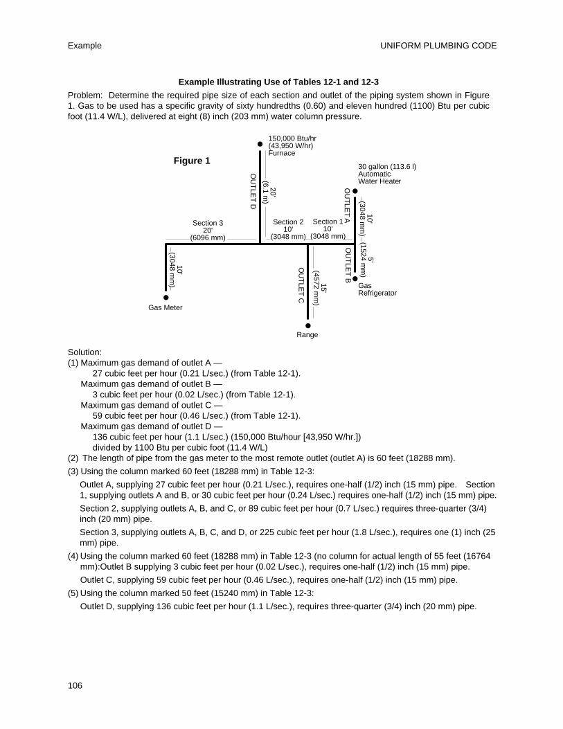
UNIFORM PLUMBING CODE
106
Example
150,000 Btu/hr(43,950 W/hr)Furnace
Gas Meter
Range
30 gallon (113.6 l)AutomaticWater Heater
Gas Refrigerator
OU
TLE
T AO
UT
LET B
OU
TLE
T C
OU
TLE
T D•
•
•
•
•5'
(1524 mm
)
15'(4572 m
m)
20'(6.1 m
)
Figure 1
Section 320'
(6096 mm)
Section 210'
(3048 mm)
Section 110'
(3048 mm)
10'(3048 m
m)
10'(3048 m
m)
Example Illustrating Use of Tables 12-1 and 12-3
Problem: Determine the required pipe size of each section and outlet of the piping system shown in Figure1. Gas to be used has a specific gravity of sixty hundredths (0.60) and eleven hundred (1100) Btu per cubicfoot (11.4 W/L), delivered at eight (8) inch (203 mm) water column pressure.
Solution:(1) Maximum gas demand of outlet A —
27 cubic feet per hour (0.21 L/sec.) (from Table 12-1).Maximum gas demand of outlet B —
3 cubic feet per hour (0.02 L/sec.) (from Table 12-1).Maximum gas demand of outlet C —
59 cubic feet per hour (0.46 L/sec.) (from Table 12-1).Maximum gas demand of outlet D —
136 cubic feet per hour (1.1 L/sec.) (150,000 Btu/hour [43,950 W/hr.]) divided by 1100 Btu per cubic foot (11.4 W/L)
(2) The length of pipe from the gas meter to the most remote outlet (outlet A) is 60 feet (18288 mm).
(3) Using the column marked 60 feet (18288 mm) in Table 12-3:
Outlet A, supplying 27 cubic feet per hour (0.21 L/sec.), requires one-half (1/2) inch (15 mm) pipe. Section1, supplying outlets A and B, or 30 cubic feet per hour (0.24 L/sec.) requires one-half (1/2) inch (15 mm) pipe.
Section 2, supplying outlets A, B, and C, or 89 cubic feet per hour (0.7 L/sec.) requires three-quarter (3/4)inch (20 mm) pipe.
Section 3, supplying outlets A, B, C, and D, or 225 cubic feet per hour (1.8 L/sec.), requires one (1) inch (25mm) pipe.
(4) Using the column marked 60 feet (18288 mm) in Table 12-3 (no column for actual length of 55 feet (16764mm):Outlet B supplying 3 cubic feet per hour (0.02 L/sec.), requires one-half (1/2) inch (15 mm) pipe.
Outlet C, supplying 59 cubic feet per hour (0.46 L/sec.), requires one-half (1/2) inch (15 mm) pipe.
(5) Using the column marked 50 feet (15240 mm) in Table 12-3:
Outlet D, supplying 136 cubic feet per hour (1.1 L/sec.), requires three-quarter (3/4) inch (20 mm) pipe.
before any medium pressure gas piping system isinstalled.
1218.3 The following shall apply to mediumpressure gas piping systems in addition to the otherrequirements of this chapter.
1218.4 Approved regulators shall be installed onmedium pressure gas piping systems, in approvedlocations and shall be accessible for servicing. Eachregulator shall have a separate vent to the outside.
Exceptions: Pounds (kg) to inches (mm) watercolumn regulators equipped with limitingorifices capable of releasing not more than five(5) cubic feet of gas per hour (0.04 L/sec.), whensupplied with medium pressure, need not bevented to an outside location when suchregulators have been approved by theAdministrative Authority and the serving gassupplier. These regulators shall:
(1) Be connected to the same piping materialused to pipe the structure. A listed gas connectormay be used to attach the low pressure pipingdownstream of the regulator to the appliancemanifold.
(2) Have an approved gas valve in the supplyline upstream of the pounds (kg) to inches (mm)water column regulator.
(3) Be accessible.
(4) Have the upstream pressure identified. Suchidentification shall be a metal tag permanentlyattached to the regulator and state: “Warning:1/2 to 5 pounds (3.4–34.5 kPa) natural gaspressure. DO NOT REMOVE”.
(5) Be installed in a location that communicateswith a ventilated area.
1218.5 An approved gas valve shall be installedimmediately preceding each regulator. All regulatorsthat may be subjected to mechanical damage shall besubstantially protected to the satisfaction of theAdministrative Authority.
1218.6 Tables 12-5 and 12-6 may be used to sizenatural gas piping system carrying three (3) or five(5) psig (20.7 or 34.5 kPa) gas. Tables 12-13 and 12-14shall be used to size copper tubing systems usingnatural gas at pressures of two (2) or five (5) psig(13.8 or 34.5 kPa). For copper tubing systemssupplying undiluted liquefied petroleum gas in thepressure ranges included in Tables 12-13 and 12-14the capacities of the tubing shall be determined bymultiplying the values in these tables by theappropriate factor in Table 12-12. The procedure todetermine the size of each section of the system issimilar to that contained in Section 1217.0 using thepipe length from the meter to the most remote
regulator on the medium pressure system and sizingthe downstream low pressure piping from Table 12-3or Table 12-11 for copper tubing systems.
1218.7 Table 12-8 may be used to size undilutedliquified petroleum gas piping systems carrying ten(10) psig (68.9 kPa) gas. The procedure to determinethe size of each section of the system is similar toSection 1217.0 using the pipe length from the firststage or tank regulator to the most remote regulatorin the second state system. Low pressure piping tobe sized from Table 12-7.
1218.8 Buried medium pressure gas piping shall beprotected from corrosion as required by Chapter 12and shall have a minimum earth cover of eighteen(18) inches (457 mm). Such piping shall be coveredwith at least six (6) inches (152 mm) of hand placedselected backfill devoid of rocks, building materials,or other matter that may damage the pipe orwrapping.
1218.2 – 1218.8FUEL PIPING
107
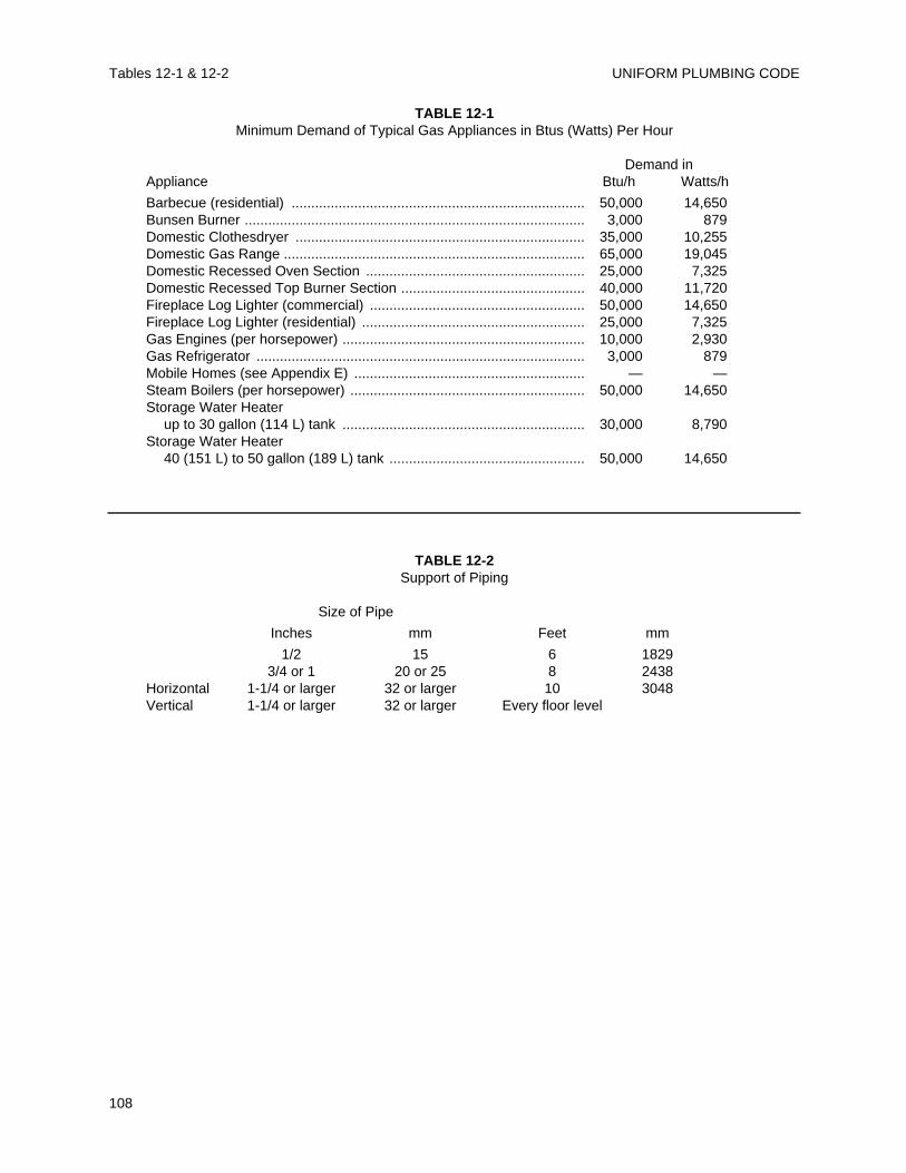
UNIFORM PLUMBING CODETables 12-1 & 12-2
108
TABLE 12-1Minimum Demand of Typical Gas Appliances in Btus (Watts) Per Hour
Demand inAppliance Btu/h Watts/h
Barbecue (residential) ........................................................................... 50,000 14,650Bunsen Burner ....................................................................................... 3,000 879Domestic Clothesdryer .......................................................................... 35,000 10,255Domestic Gas Range ............................................................................. 65,000 19,045Domestic Recessed Oven Section ........................................................ 25,000 7,325Domestic Recessed Top Burner Section ............................................... 40,000 11,720Fireplace Log Lighter (commercial) ....................................................... 50,000 14,650Fireplace Log Lighter (residential) ......................................................... 25,000 7,325Gas Engines (per horsepower) .............................................................. 10,000 2,930Gas Refrigerator .................................................................................... 3,000 879Mobile Homes (see Appendix E) ........................................................... — —Steam Boilers (per horsepower) ............................................................ 50,000 14,650Storage Water Heater
up to 30 gallon (114 L) tank .............................................................. 30,000 8,790Storage Water Heater
40 (151 L) to 50 gallon (189 L) tank .................................................. 50,000 14,650
TABLE 12-2Support of Piping
Size of Pipe
Inches mm Feet mm
1/2 15 6 18293/4 or 1 20 or 25 8 2438
Horizontal 1-1/4 or larger 32 or larger 10 3048Vertical 1-1/4 or larger 32 or larger Every floor level
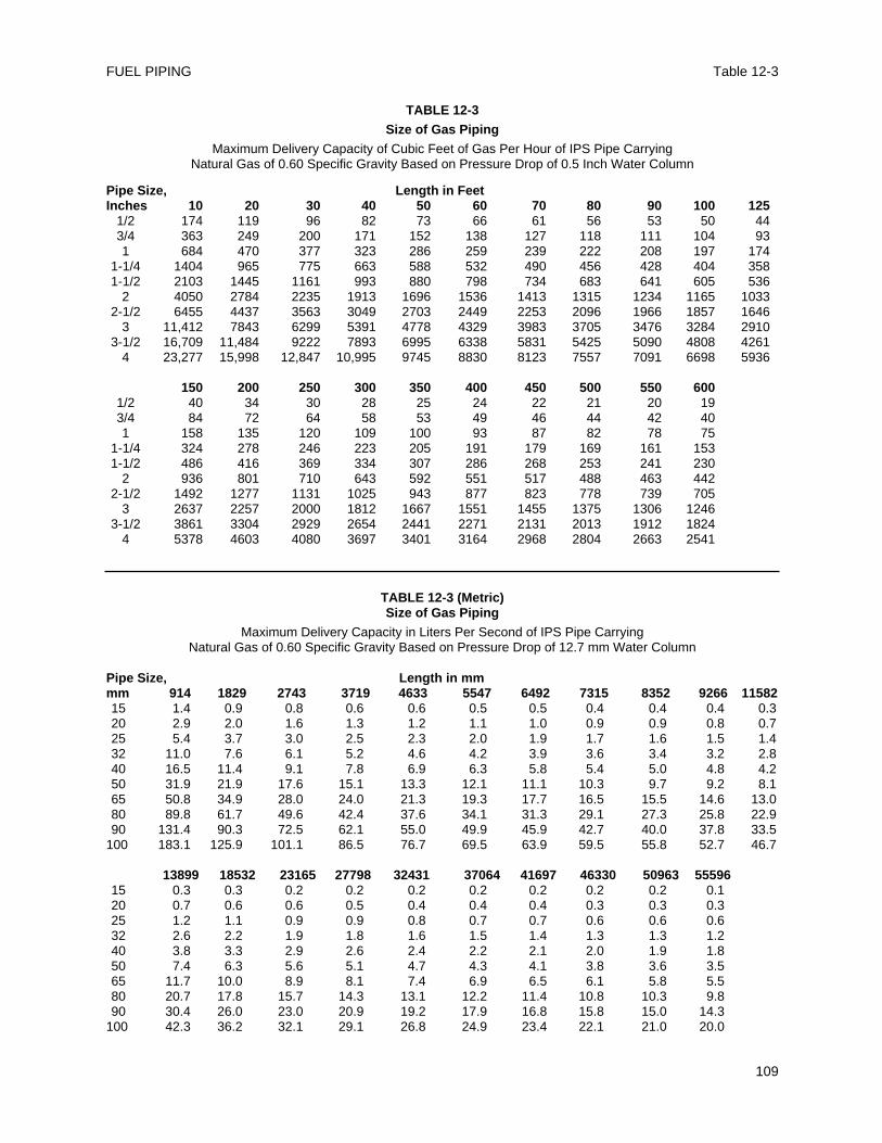
Table 12-3FUEL PIPING
109
TABLE 12-3Size of Gas Piping
Maximum Delivery Capacity of Cubic Feet of Gas Per Hour of IPS Pipe CarryingNatural Gas of 0.60 Specific Gravity Based on Pressure Drop of 0.5 Inch Water Column
Pipe Size, Length in FeetInches 10 20 30 40 50 60 70 80 90 100 125
1/2 174 119 96 82 73 66 61 56 53 50 443/4 363 249 200 171 152 138 127 118 111 104 931 684 470 377 323 286 259 239 222 208 197 174
1-1/4 1404 965 775 663 588 532 490 456 428 404 3581-1/2 2103 1445 1161 993 880 798 734 683 641 605 536
2 4050 2784 2235 1913 1696 1536 1413 1315 1234 1165 10332-1/2 6455 4437 3563 3049 2703 2449 2253 2096 1966 1857 1646
3 11,412 7843 6299 5391 4778 4329 3983 3705 3476 3284 29103-1/2 16,709 11,484 9222 7893 6995 6338 5831 5425 5090 4808 4261
4 23,277 15,998 12,847 10,995 9745 8830 8123 7557 7091 6698 5936
150 200 250 300 350 400 450 500 550 6001/2 40 34 30 28 25 24 22 21 20 193/4 84 72 64 58 53 49 46 44 42 401 158 135 120 109 100 93 87 82 78 75
1-1/4 324 278 246 223 205 191 179 169 161 1531-1/2 486 416 369 334 307 286 268 253 241 230
2 936 801 710 643 592 551 517 488 463 4422-1/2 1492 1277 1131 1025 943 877 823 778 739 705
3 2637 2257 2000 1812 1667 1551 1455 1375 1306 12463-1/2 3861 3304 2929 2654 2441 2271 2131 2013 1912 1824
4 5378 4603 4080 3697 3401 3164 2968 2804 2663 2541
TABLE 12-3 (Metric)Size of Gas Piping
Maximum Delivery Capacity in Liters Per Second of IPS Pipe CarryingNatural Gas of 0.60 Specific Gravity Based on Pressure Drop of 12.7 mm Water Column
Pipe Size, Length in mmmm 914 1829 2743 3719 4633 5547 6492 7315 8352 9266 1158215 1.4 0.9 0.8 0.6 0.6 0.5 0.5 0.4 0.4 0.4 0.320 2.9 2.0 1.6 1.3 1.2 1.1 1.0 0.9 0.9 0.8 0.725 5.4 3.7 3.0 2.5 2.3 2.0 1.9 1.7 1.6 1.5 1.432 11.0 7.6 6.1 5.2 4.6 4.2 3.9 3.6 3.4 3.2 2.840 16.5 11.4 9.1 7.8 6.9 6.3 5.8 5.4 5.0 4.8 4.250 31.9 21.9 17.6 15.1 13.3 12.1 11.1 10.3 9.7 9.2 8.165 50.8 34.9 28.0 24.0 21.3 19.3 17.7 16.5 15.5 14.6 13.080 89.8 61.7 49.6 42.4 37.6 34.1 31.3 29.1 27.3 25.8 22.990 131.4 90.3 72.5 62.1 55.0 49.9 45.9 42.7 40.0 37.8 33.5
100 183.1 125.9 101.1 86.5 76.7 69.5 63.9 59.5 55.8 52.7 46.7
13899 18532 23165 27798 32431 37064 41697 46330 50963 5559615 0.3 0.3 0.2 0.2 0.2 0.2 0.2 0.2 0.2 0.120 0.7 0.6 0.6 0.5 0.4 0.4 0.4 0.3 0.3 0.325 1.2 1.1 0.9 0.9 0.8 0.7 0.7 0.6 0.6 0.632 2.6 2.2 1.9 1.8 1.6 1.5 1.4 1.3 1.3 1.240 3.8 3.3 2.9 2.6 2.4 2.2 2.1 2.0 1.9 1.850 7.4 6.3 5.6 5.1 4.7 4.3 4.1 3.8 3.6 3.565 11.7 10.0 8.9 8.1 7.4 6.9 6.5 6.1 5.8 5.580 20.7 17.8 15.7 14.3 13.1 12.2 11.4 10.8 10.3 9.890 30.4 26.0 23.0 20.9 19.2 17.9 16.8 15.8 15.0 14.3
100 42.3 36.2 32.1 29.1 26.8 24.9 23.4 22.1 21.0 20.0
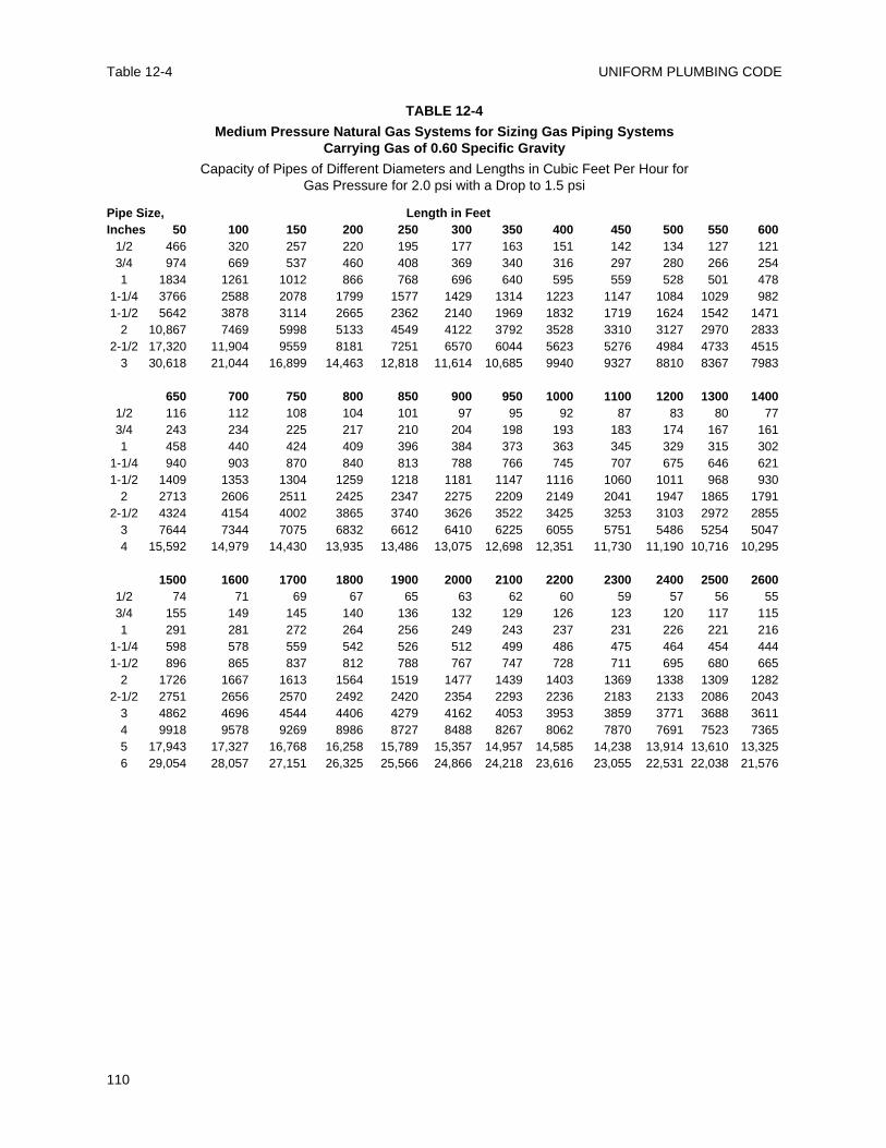
UNIFORM PLUMBING CODETable 12-4
110
TABLE 12-4
Medium Pressure Natural Gas Systems for Sizing Gas Piping Systems Carrying Gas of 0.60 Specific Gravity
Capacity of Pipes of Different Diameters and Lengths in Cubic Feet Per Hour for Gas Pressure for 2.0 psi with a Drop to 1.5 psi
Pipe Size, Length in FeetInches 50 100 150 200 250 300 350 400 450 500 550 600
1/2 466 320 257 220 195 177 163 151 142 134 127 1213/4 974 669 537 460 408 369 340 316 297 280 266 2541 1834 1261 1012 866 768 696 640 595 559 528 501 478
1-1/4 3766 2588 2078 1799 1577 1429 1314 1223 1147 1084 1029 9821-1/2 5642 3878 3114 2665 2362 2140 1969 1832 1719 1624 1542 1471
2 10,867 7469 5998 5133 4549 4122 3792 3528 3310 3127 2970 28332-1/2 17,320 11,904 9559 8181 7251 6570 6044 5623 5276 4984 4733 4515
3 30,618 21,044 16,899 14,463 12,818 11,614 10,685 9940 9327 8810 8367 7983
650 700 750 800 850 900 950 1000 1100 1200 1300 14001/2 116 112 108 104 101 97 95 92 87 83 80 773/4 243 234 225 217 210 204 198 193 183 174 167 1611 458 440 424 409 396 384 373 363 345 329 315 302
1-1/4 940 903 870 840 813 788 766 745 707 675 646 6211-1/2 1409 1353 1304 1259 1218 1181 1147 1116 1060 1011 968 930
2 2713 2606 2511 2425 2347 2275 2209 2149 2041 1947 1865 17912-1/2 4324 4154 4002 3865 3740 3626 3522 3425 3253 3103 2972 2855
3 7644 7344 7075 6832 6612 6410 6225 6055 5751 5486 5254 50474 15,592 14,979 14,430 13,935 13,486 13,075 12,698 12,351 11,730 11,190 10,716 10,295
1500 1600 1700 1800 1900 2000 2100 2200 2300 2400 2500 26001/2 74 71 69 67 65 63 62 60 59 57 56 553/4 155 149 145 140 136 132 129 126 123 120 117 1151 291 281 272 264 256 249 243 237 231 226 221 216
1-1/4 598 578 559 542 526 512 499 486 475 464 454 4441-1/2 896 865 837 812 788 767 747 728 711 695 680 665
2 1726 1667 1613 1564 1519 1477 1439 1403 1369 1338 1309 12822-1/2 2751 2656 2570 2492 2420 2354 2293 2236 2183 2133 2086 2043
3 4862 4696 4544 4406 4279 4162 4053 3953 3859 3771 3688 36114 9918 9578 9269 8986 8727 8488 8267 8062 7870 7691 7523 73655 17,943 17,327 16,768 16,258 15,789 15,357 14,957 14,585 14,238 13,914 13,610 13,3256 29,054 28,057 27,151 26,325 25,566 24,866 24,218 23,616 23,055 22,531 22,038 21,576
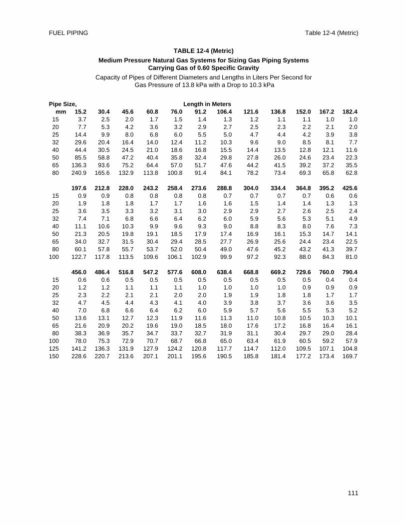
Table 12-4 (Metric)FUEL PIPING
111
TABLE 12-4 (Metric)
Medium Pressure Natural Gas Systems for Sizing Gas Piping Systems Carrying Gas of 0.60 Specific Gravity
Capacity of Pipes of Different Diameters and Lengths in Liters Per Second forGas Pressure of 13.8 kPa with a Drop to 10.3 kPa
Pipe Size, Length in Metersmm 15.2 30.4 45.6 60.8 76.0 91.2 106.4 121.6 136.8 152.0 167.2 182.4
15 3.7 2.5 2.0 1.7 1.5 1.4 1.3 1.2 1.1 1.1 1.0 1.020 7.7 5.3 4.2 3.6 3.2 2.9 2.7 2.5 2.3 2.2 2.1 2.025 14.4 9.9 8.0 6.8 6.0 5.5 5.0 4.7 4.4 4.2 3.9 3.832 29.6 20.4 16.4 14.0 12.4 11.2 10.3 9.6 9.0 8.5 8.1 7.740 44.4 30.5 24.5 21.0 18.6 16.8 15.5 14.4 13.5 12.8 12.1 11.650 85.5 58.8 47.2 40.4 35.8 32.4 29.8 27.8 26.0 24.6 23.4 22.365 136.3 93.6 75.2 64.4 57.0 51.7 47.6 44.2 41.5 39.2 37.2 35.580 240.9 165.6 132.9 113.8 100.8 91.4 84.1 78.2 73.4 69.3 65.8 62.8
197.6 212.8 228.0 243.2 258.4 273.6 288.8 304.0 334.4 364.8 395.2 425.615 0.9 0.9 0.8 0.8 0.8 0.8 0.7 0.7 0.7 0.7 0.6 0.620 1.9 1.8 1.8 1.7 1.7 1.6 1.6 1.5 1.4 1.4 1.3 1.325 3.6 3.5 3.3 3.2 3.1 3.0 2.9 2.9 2.7 2.6 2.5 2.432 7.4 7.1 6.8 6.6 6.4 6.2 6.0 5.9 5.6 5.3 5.1 4.940 11.1 10.6 10.3 9.9 9.6 9.3 9.0 8.8 8.3 8.0 7.6 7.350 21.3 20.5 19.8 19.1 18.5 17.9 17.4 16.9 16.1 15.3 14.7 14.165 34.0 32.7 31.5 30.4 29.4 28.5 27.7 26.9 25.6 24.4 23.4 22.580 60.1 57.8 55.7 53.7 52.0 50.4 49.0 47.6 45.2 43.2 41.3 39.7
100 122.7 117.8 113.5 109.6 106.1 102.9 99.9 97.2 92.3 88.0 84.3 81.0
456.0 486.4 516.8 547.2 577.6 608.0 638.4 668.8 669.2 729.6 760.0 790.415 0.6 0.6 0.5 0.5 0.5 0.5 0.5 0.5 0.5 0.5 0.4 0.420 1.2 1.2 1.1 1.1 1.1 1.0 1.0 1.0 1.0 0.9 0.9 0.925 2.3 2.2 2.1 2.1 2.0 2.0 1.9 1.9 1.8 1.8 1.7 1.732 4.7 4.5 4.4 4.3 4.1 4.0 3.9 3.8 3.7 3.6 3.6 3.5 40 7.0 6.8 6.6 6.4 6.2 6.0 5.9 5.7 5.6 5.5 5.3 5.250 13.6 13.1 12.7 12.3 11.9 11.6 11.3 11.0 10.8 10.5 10.3 10.165 21.6 20.9 20.2 19.6 19.0 18.5 18.0 17.6 17.2 16.8 16.4 16.180 38.3 36.9 35.7 34.7 33.7 32.7 31.9 31.1 30.4 29.7 29.0 28.4
100 78.0 75.3 72.9 70.7 68.7 66.8 65.0 63.4 61.9 60.5 59.2 57.9125 141.2 136.3 131.9 127.9 124.2 120.8 117.7 114.7 112.0 109.5 107.1 104.8150 228.6 220.7 213.6 207.1 201.1 195.6 190.5 185.8 181.4 177.2 173.4 169.7
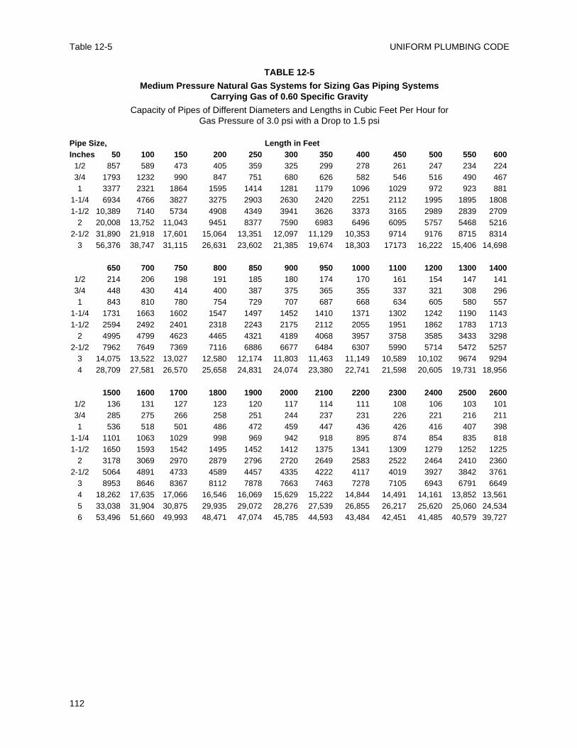
UNIFORM PLUMBING CODETable 12-5
112
TABLE 12-5
Medium Pressure Natural Gas Systems for Sizing Gas Piping Systems Carrying Gas of 0.60 Specific Gravity
Capacity of Pipes of Different Diameters and Lengths in Cubic Feet Per Hour for Gas Pressure of 3.0 psi with a Drop to 1.5 psi
Pipe Size, Length in FeetInches 50 100 150 200 250 300 350 400 450 500 550 600
1/2 857 589 473 405 359 325 299 278 261 247 234 2243/4 1793 1232 990 847 751 680 626 582 546 516 490 4671 3377 2321 1864 1595 1414 1281 1179 1096 1029 972 923 881
1-1/4 6934 4766 3827 3275 2903 2630 2420 2251 2112 1995 1895 18081-1/2 10,389 7140 5734 4908 4349 3941 3626 3373 3165 2989 2839 2709
2 20,008 13,752 11,043 9451 8377 7590 6983 6496 6095 5757 5468 52162-1/2 31,890 21,918 17,601 15,064 13,351 12,097 11,129 10,353 9714 9176 8715 8314
3 56,376 38,747 31,115 26,631 23,602 21,385 19,674 18,303 17173 16,222 15,406 14,698
650 700 750 800 850 900 950 1000 1100 1200 1300 14001/2 214 206 198 191 185 180 174 170 161 154 147 1413/4 448 430 414 400 387 375 365 355 337 321 308 2961 843 810 780 754 729 707 687 668 634 605 580 557
1-1/4 1731 1663 1602 1547 1497 1452 1410 1371 1302 1242 1190 11431-1/2 2594 2492 2401 2318 2243 2175 2112 2055 1951 1862 1783 1713
2 4995 4799 4623 4465 4321 4189 4068 3957 3758 3585 3433 32982-1/2 7962 7649 7369 7116 6886 6677 6484 6307 5990 5714 5472 5257
3 14,075 13,522 13,027 12,580 12,174 11,803 11,463 11,149 10,589 10,102 9674 92944 28,709 27,581 26,570 25,658 24,831 24,074 23,380 22,741 21,598 20,605 19,731 18,956
1500 1600 1700 1800 1900 2000 2100 2200 2300 2400 2500 26001/2 136 131 127 123 120 117 114 111 108 106 103 1013/4 285 275 266 258 251 244 237 231 226 221 216 2111 536 518 501 486 472 459 447 436 426 416 407 398
1-1/4 1101 1063 1029 998 969 942 918 895 874 854 835 8181-1/2 1650 1593 1542 1495 1452 1412 1375 1341 1309 1279 1252 1225
2 3178 3069 2970 2879 2796 2720 2649 2583 2522 2464 2410 23602-1/2 5064 4891 4733 4589 4457 4335 4222 4117 4019 3927 3842 3761
3 8953 8646 8367 8112 7878 7663 7463 7278 7105 6943 6791 66494 18,262 17,635 17,066 16,546 16,069 15,629 15,222 14,844 14,491 14,161 13,852 13,5615 33,038 31,904 30,875 29,935 29,072 28,276 27,539 26,855 26,217 25,620 25,060 24,5346 53,496 51,660 49,993 48,471 47,074 45,785 44,593 43,484 42,451 41,485 40,579 39,727
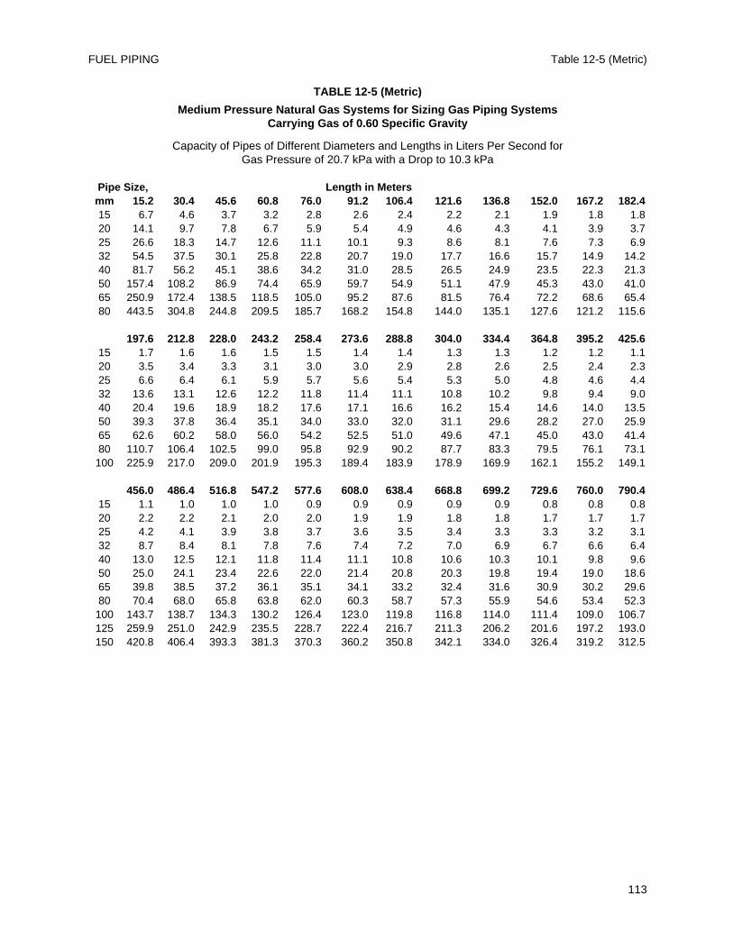
Table 12-5 (Metric)FUEL PIPING
113
TABLE 12-5 (Metric)
Medium Pressure Natural Gas Systems for Sizing Gas Piping Systems Carrying Gas of 0.60 Specific Gravity
Capacity of Pipes of Different Diameters and Lengths in Liters Per Second for Gas Pressure of 20.7 kPa with a Drop to 10.3 kPa
Pipe Size, Length in Metersmm 15.2 30.4 45.6 60.8 76.0 91.2 106.4 121.6 136.8 152.0 167.2 182.415 6.7 4.6 3.7 3.2 2.8 2.6 2.4 2.2 2.1 1.9 1.8 1.820 14.1 9.7 7.8 6.7 5.9 5.4 4.9 4.6 4.3 4.1 3.9 3.725 26.6 18.3 14.7 12.6 11.1 10.1 9.3 8.6 8.1 7.6 7.3 6.932 54.5 37.5 30.1 25.8 22.8 20.7 19.0 17.7 16.6 15.7 14.9 14.240 81.7 56.2 45.1 38.6 34.2 31.0 28.5 26.5 24.9 23.5 22.3 21.350 157.4 108.2 86.9 74.4 65.9 59.7 54.9 51.1 47.9 45.3 43.0 41.065 250.9 172.4 138.5 118.5 105.0 95.2 87.6 81.5 76.4 72.2 68.6 65.480 443.5 304.8 244.8 209.5 185.7 168.2 154.8 144.0 135.1 127.6 121.2 115.6
197.6 212.8 228.0 243.2 258.4 273.6 288.8 304.0 334.4 364.8 395.2 425.615 1.7 1.6 1.6 1.5 1.5 1.4 1.4 1.3 1.3 1.2 1.2 1.120 3.5 3.4 3.3 3.1 3.0 3.0 2.9 2.8 2.6 2.5 2.4 2.325 6.6 6.4 6.1 5.9 5.7 5.6 5.4 5.3 5.0 4.8 4.6 4.432 13.6 13.1 12.6 12.2 11.8 11.4 11.1 10.8 10.2 9.8 9.4 9.040 20.4 19.6 18.9 18.2 17.6 17.1 16.6 16.2 15.4 14.6 14.0 13.550 39.3 37.8 36.4 35.1 34.0 33.0 32.0 31.1 29.6 28.2 27.0 25.965 62.6 60.2 58.0 56.0 54.2 52.5 51.0 49.6 47.1 45.0 43.0 41.480 110.7 106.4 102.5 99.0 95.8 92.9 90.2 87.7 83.3 79.5 76.1 73.1100 225.9 217.0 209.0 201.9 195.3 189.4 183.9 178.9 169.9 162.1 155.2 149.1
456.0 486.4 516.8 547.2 577.6 608.0 638.4 668.8 699.2 729.6 760.0 790.415 1.1 1.0 1.0 1.0 0.9 0.9 0.9 0.9 0.9 0.8 0.8 0.820 2.2 2.2 2.1 2.0 2.0 1.9 1.9 1.8 1.8 1.7 1.7 1.725 4.2 4.1 3.9 3.8 3.7 3.6 3.5 3.4 3.3 3.3 3.2 3.132 8.7 8.4 8.1 7.8 7.6 7.4 7.2 7.0 6.9 6.7 6.6 6.440 13.0 12.5 12.1 11.8 11.4 11.1 10.8 10.6 10.3 10.1 9.8 9.650 25.0 24.1 23.4 22.6 22.0 21.4 20.8 20.3 19.8 19.4 19.0 18.665 39.8 38.5 37.2 36.1 35.1 34.1 33.2 32.4 31.6 30.9 30.2 29.680 70.4 68.0 65.8 63.8 62.0 60.3 58.7 57.3 55.9 54.6 53.4 52.3100 143.7 138.7 134.3 130.2 126.4 123.0 119.8 116.8 114.0 111.4 109.0 106.7125 259.9 251.0 242.9 235.5 228.7 222.4 216.7 211.3 206.2 201.6 197.2 193.0150 420.8 406.4 393.3 381.3 370.3 360.2 350.8 342.1 334.0 326.4 319.2 312.5
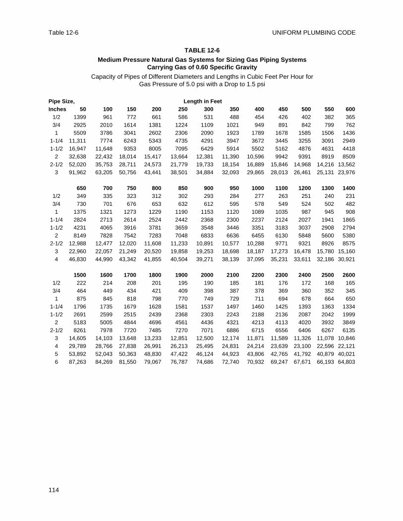
UNIFORM PLUMBING CODETable 12-6
114
TABLE 12-6
Medium Pressure Natural Gas Systems for Sizing Gas Piping Systems Carrying Gas of 0.60 Specific Gravity
Capacity of Pipes of Different Diameters and Lengths in Cubic Feet Per Hour for Gas Pressure of 5.0 psi with a Drop to 1.5 psi
Pipe Size, Length in FeetInches 50 100 150 200 250 300 350 400 450 500 550 600
1/2 1399 961 772 661 586 531 488 454 426 402 382 3653/4 2925 2010 1614 1381 1224 1109 1021 949 891 842 799 7621 5509 3786 3041 2602 2306 2090 1923 1789 1678 1585 1506 1436
1-1/4 11,311 7774 6243 5343 4735 4291 3947 3672 3445 3255 3091 29491-1/2 16,947 11,648 9353 8005 7095 6429 5914 5502 5162 4876 4631 4418
2 32,638 22,432 18,014 15,417 13,664 12,381 11,390 10,596 9942 9391 8919 85092-1/2 52,020 35,753 28,711 24,573 21,779 19,733 18,154 16,889 15,846 14,968 14,216 13,562
3 91,962 63,205 50,756 43,441 38,501 34,884 32,093 29,865 28,013 26,461 25,131 23,976
650 700 750 800 850 900 950 1000 1100 1200 1300 14001/2 349 335 323 312 302 293 284 277 263 251 240 2313/4 730 701 676 653 632 612 595 578 549 524 502 4821 1375 1321 1273 1229 1190 1153 1120 1089 1035 987 945 908
1-1/4 2824 2713 2614 2524 2442 2368 2300 2237 2124 2027 1941 18651-1/2 4231 4065 3916 3781 3659 3548 3446 3351 3183 3037 2908 2794
2 8149 7828 7542 7283 7048 6833 6636 6455 6130 5848 5600 53802-1/2 12,988 12,477 12,020 11,608 11,233 10,891 10,577 10,288 9771 9321 8926 8575
3 22,960 22,057 21,249 20,520 19,858 19,253 18,698 18,187 17,273 16,478 15,780 15,1604 46,830 44,990 43,342 41,855 40,504 39,271 38,139 37,095 35,231 33,611 32,186 30,921
1500 1600 1700 1800 1900 2000 2100 2200 2300 2400 2500 26001/2 222 214 208 201 195 190 185 181 176 172 168 1653/4 464 449 434 421 409 398 387 378 369 360 352 3451 875 845 818 798 770 749 729 711 694 678 664 650
1-1/4 1796 1735 1679 1628 1581 1537 1497 1460 1425 1393 1363 13341-1/2 2691 2599 2515 2439 2368 2303 2243 2188 2136 2087 2042 1999
2 5183 5005 4844 4696 4561 4436 4321 4213 4113 4020 3932 38492-1/2 8261 7978 7720 7485 7270 7071 6886 6715 6556 6406 6267 6135
3 14,605 14,103 13,648 13,233 12,851 12,500 12,174 11,871 11,589 11,326 11,078 10,8464 29,789 28,766 27,838 26,991 26,213 25,495 24,831 24,214 23,639 23,100 22,596 22,1215 53,892 52,043 50,363 48,830 47,422 46,124 44,923 43,806 42,765 41,792 40,879 40,0216 87,263 84,269 81,550 79,067 76,787 74,686 72,740 70,932 69,247 67,671 66,193 64,803
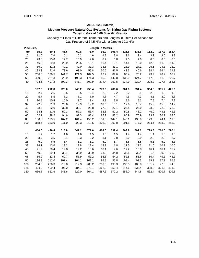
Table 12-6 (Metric)FUEL PIPING
115
TABLE 12-6 (Metric)
Medium Pressure Natural Gas Systems for Sizing Gas Piping Systems Carrying Gas of 0.60 Specific Gravity
Capacity of Pipes of Different Diameters and Lengths in Liters Per Second for Gas Pressure of 34.5 kPa with a Drop to 10.3 kPa
Pipe Size, Length in Metersmm 15.2 30.4 45.6 60.8 76.0 91.2 106.4 121.6 136.8 152.0 167.2 182.415 11.0 7.6 6.1 5.2 4.6 4.2 3.8 3.6 3.4 3.2 3.0 2.920 23.0 15.8 12.7 10.9 9.6 8.7 8.0 7.5 7.0 6.6 6.3 6.025 46.3 29.8 23.9 20.5 18.1 16.4 15.1 14.1 13.0 12.5 11.8 11.332 89.0 61.2 49.1 42.0 37.3 33.8 31.1 28.9 27.1 25.6 24.3 23.240 133.3 91.6 73.6 63.0 55.8 50.6 46.5 43.3 40.6 38.4 36.4 34.850 256.8 176.5 141.7 121.3 107.5 97.4 89.6 83.4 78.2 73.9 70.2 66.965 409.2 281.3 225.9 193.3 171.3 155.2 142.8 132.9 124.7 117.8 111.8 106.780 723.5 497.2 399.3 341.7 302.9 274.4 252.5 234.9 220.4 208.2 197.7 188.6
197.6 212.8 228.0 243.2 258.4 273.6 288.0 304.0 334.4 364.8 395.2 425.615 2.7 2.6 2.5 2.5 2.4 2.3 2.2 2.2 2.1 2.0 1.9 1.820 5.7 5.5 5.3 5.1 5.0 4.8 4.7 4.6 4.3 4.1 3.9 3.81 10.8 10.4 10.0 9.7 9.4 9.1 8.8 8.6 8.1 7.8 7.4 7.1
32 22.2 21.3 20.6 19.9 19.2 18.6 18.1 17.6 16.7 15.9 15.3 14.740 33.3 32.0 30.8 39.7 28.8 27.9 27.1 26.4 25.0 23.9 22.9 22.050 64.1 61.6 59.3 57.3 55.4 53.8 52.2 50.8 48.2 46.0 44.1 42.365 102.2 98.2 94.6 91.3 88.4 85.7 83.2 80.9 76.9 73.3 70.2 67.580 180.6 173.5 167.2 161.4 156.2 151.5 147.1 143.1 135.9 129.6 124.1 119.3
100 368.4 353.9 341.0 329.3 318.6 308.9 300.0 291.8 277.2 264.4 253.2 243.3
456.0 486.4 516.8 547.2 577.6 608.0 638.4 668.8 699.2 729.6 760.0 790.415 1.7 1.7 1.6 1.6 1.5 1.5 1.5 1.4 1.4 1.4 1.3 1.320 3.7 3.5 3.4 3.3 3.2 3.1 3.0 3.0 2.9 2.8 2.8 2.725 6.9 6.6 6.4 6.2 6.1 5.9 5.7 5.6 5.5 5.3 5.2 5.132 14.1 13.6 13.2 12.8 12.4 12.1 11.8 11.5 11.2 11.0 10.7 10.540 21.2 20.4 19.8 19.2 18.6 18.1 17.6 17.2 16.8 16.4 16.1 15.750 40.8 39.4 38.1 36.9 35.9 34.9 34.0 33.1 32.4 31.6 30.9 30.365 65.0 62.8 60.7 58.9 57.2 55.6 54.2 52.8 51.6 50.4 49.3 48.380 114.9 111.0 107.4 104.1 101.1 98.3 95.8 93.4 91.2 89.1 87.2 85.3
100 234.3 226.3 219.0 212.3 206.2 200.6 195.3 190.5 186.0 181.7 177.8 174.0125 424.0 409.4 396.2 384.1 373.1 362.9 353.4 344.6 336.4 328.8 321.6 314.8150 686.5 662.9 641.6 622.0 604.1 587.6 572.2 558.0 544.8 532.4 520.7 509.8
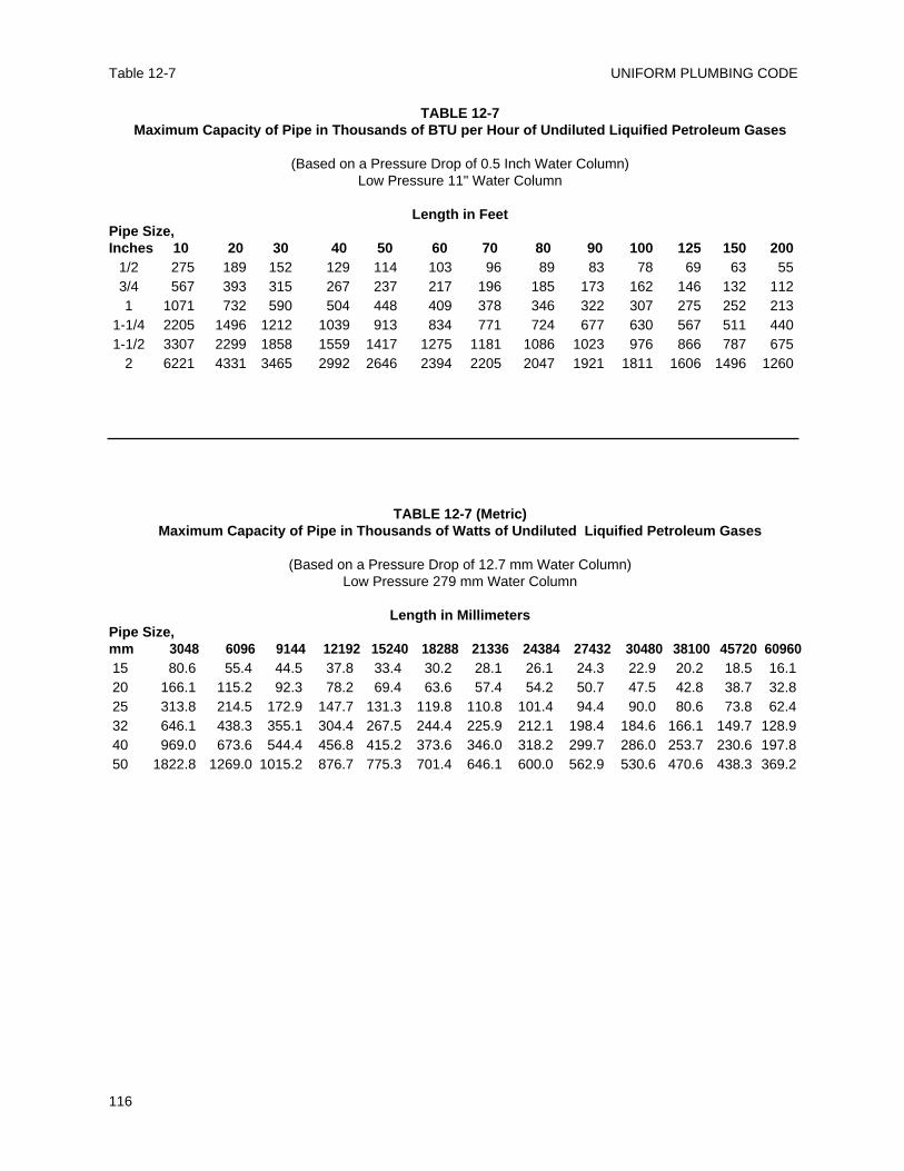
UNIFORM PLUMBING CODETable 12-7
116
TABLE 12-7Maximum Capacity of Pipe in Thousands of BTU per Hour of Undiluted Liquified Petroleum Gases
(Based on a Pressure Drop of 0.5 Inch Water Column)Low Pressure 11" Water Column
Length in FeetPipe Size,Inches 10 20 30 40 50 60 70 80 90 100 125 150 200
1/2 275 189 152 129 114 103 96 89 83 78 69 63 553/4 567 393 315 267 237 217 196 185 173 162 146 132 1121 1071 732 590 504 448 409 378 346 322 307 275 252 213
1-1/4 2205 1496 1212 1039 913 834 771 724 677 630 567 511 4401-1/2 3307 2299 1858 1559 1417 1275 1181 1086 1023 976 866 787 675
2 6221 4331 3465 2992 2646 2394 2205 2047 1921 1811 1606 1496 1260
TABLE 12-7 (Metric)Maximum Capacity of Pipe in Thousands of Watts of Undiluted Liquified Petroleum Gases
(Based on a Pressure Drop of 12.7 mm Water Column)Low Pressure 279 mm Water Column
Length in MillimetersPipe Size,mm 3048 6096 9144 12192 15240 18288 21336 24384 27432 30480 38100 45720 6096015 80.6 55.4 44.5 37.8 33.4 30.2 28.1 26.1 24.3 22.9 20.2 18.5 16.120 166.1 115.2 92.3 78.2 69.4 63.6 57.4 54.2 50.7 47.5 42.8 38.7 32.825 313.8 214.5 172.9 147.7 131.3 119.8 110.8 101.4 94.4 90.0 80.6 73.8 62.432 646.1 438.3 355.1 304.4 267.5 244.4 225.9 212.1 198.4 184.6 166.1 149.7 128.940 969.0 673.6 544.4 456.8 415.2 373.6 346.0 318.2 299.7 286.0 253.7 230.6 197.850 1822.8 1269.0 1015.2 876.7 775.3 701.4 646.1 600.0 562.9 530.6 470.6 438.3 369.2
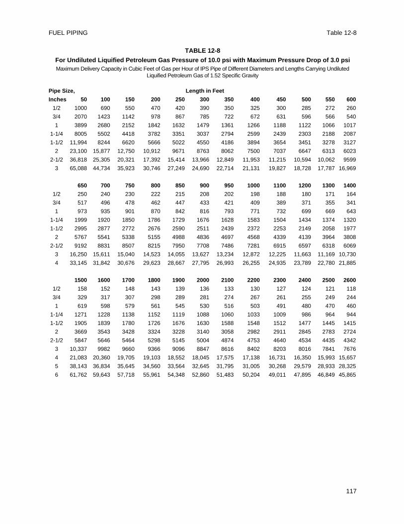
Table 12-8FUEL PIPING
117
TABLE 12-8
For Undiluted Liquified Petroleum Gas Pressure of 10.0 psi with Maximum Pressure Drop of 3.0 psiMaximum Delivery Capacity in Cubic Feet of Gas per Hour of IPS Pipe of Different Diameters and Lengths Carrying Undiluted
Liquified Petroleum Gas of 1.52 Specific Gravity
Pipe Size, Length in Feet
Inches 50 100 150 200 250 300 350 400 450 500 550 600
1/2 1000 690 550 470 420 390 350 325 300 285 272 260
3/4 2070 1423 1142 978 867 785 722 672 631 596 566 540
1 3899 2680 2152 1842 1632 1479 1361 1266 1188 1122 1066 1017
1-1/4 8005 5502 4418 3782 3351 3037 2794 2599 2439 2303 2188 2087
1-1/2 11,994 8244 6620 5666 5022 4550 4186 3894 3654 3451 3278 3127
2 23,100 15,877 12,750 10,912 9671 8763 8062 7500 7037 6647 6313 6023
2-1/2 36,818 25,305 20,321 17,392 15,414 13,966 12,849 11,953 11,215 10,594 10,062 9599
3 65,088 44,734 35,923 30,746 27,249 24,690 22,714 21,131 19,827 18,728 17,787 16,969
650 700 750 800 850 900 950 1000 1100 1200 1300 1400
1/2 250 240 230 222 215 208 202 198 188 180 171 164
3/4 517 496 478 462 447 433 421 409 389 371 355 341
1 973 935 901 870 842 816 793 771 732 699 669 643
1-1/4 1999 1920 1850 1786 1729 1676 1628 1583 1504 1434 1374 1320
1-1/2 2995 2877 2772 2676 2590 2511 2439 2372 2253 2149 2058 1977
2 5767 5541 5338 5155 4988 4836 4697 4568 4339 4139 3964 3808
2-1/2 9192 8831 8507 8215 7950 7708 7486 7281 6915 6597 6318 6069
3 16,250 15,611 15,040 14,523 14,055 13,627 13,234 12,872 12,225 11,663 11,169 10,730
4 33,145 31,842 30,676 29,623 28,667 27,795 26,993 26,255 24,935 23,789 22,780 21,885
1500 1600 1700 1800 1900 2000 2100 2200 2300 2400 2500 2600
1/2 158 152 148 143 139 136 133 130 127 124 121 118
3/4 329 317 307 298 289 281 274 267 261 255 249 244
1 619 598 579 561 545 530 516 503 491 480 470 460
1-1/4 1271 1228 1138 1152 1119 1088 1060 1033 1009 986 964 944
1-1/2 1905 1839 1780 1726 1676 1630 1588 1548 1512 1477 1445 1415
2 3669 3543 3428 3324 3228 3140 3058 2982 2911 2845 2783 2724
2-1/2 5847 5646 5464 5298 5145 5004 4874 4753 4640 4534 4435 4342
3 10,337 9982 9660 9366 9096 8847 8616 8402 8203 8016 7841 7676
4 21,083 20,360 19,705 19,103 18,552 18,045 17,575 17,138 16,731 16,350 15,993 15,657
5 38,143 36,834 35,645 34,560 33,564 32,645 31,795 31,005 30,268 29,579 28,933 28,325
6 61,762 59,643 57,718 55,961 54,348 52,860 51,483 50,204 49,011 47,895 46,849 45,865
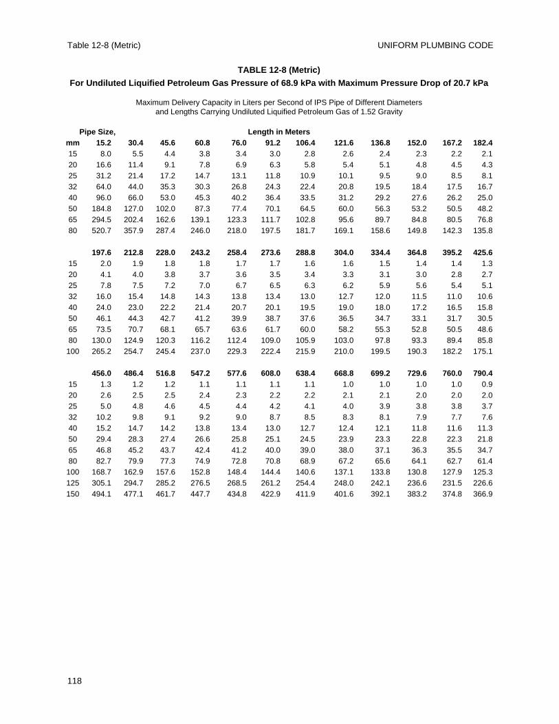
UNIFORM PLUMBING CODETable 12-8 (Metric)
118
TABLE 12-8 (Metric)
For Undiluted Liquified Petroleum Gas Pressure of 68.9 kPa with Maximum Pressure Drop of 20.7 kPa
Maximum Delivery Capacity in Liters per Second of IPS Pipe of Different Diameters and Lengths Carrying Undiluted Liquified Petroleum Gas of 1.52 Gravity
Pipe Size, Length in Metersmm 15.2 30.4 45.6 60.8 76.0 91.2 106.4 121.6 136.8 152.0 167.2 182.415 8.0 5.5 4.4 3.8 3.4 3.0 2.8 2.6 2.4 2.3 2.2 2.120 16.6 11.4 9.1 7.8 6.9 6.3 5.8 5.4 5.1 4.8 4.5 4.325 31.2 21.4 17.2 14.7 13.1 11.8 10.9 10.1 9.5 9.0 8.5 8.132 64.0 44.0 35.3 30.3 26.8 24.3 22.4 20.8 19.5 18.4 17.5 16.740 96.0 66.0 53.0 45.3 40.2 36.4 33.5 31.2 29.2 27.6 26.2 25.050 184.8 127.0 102.0 87.3 77.4 70.1 64.5 60.0 56.3 53.2 50.5 48.265 294.5 202.4 162.6 139.1 123.3 111.7 102.8 95.6 89.7 84.8 80.5 76.880 520.7 357.9 287.4 246.0 218.0 197.5 181.7 169.1 158.6 149.8 142.3 135.8
197.6 212.8 228.0 243.2 258.4 273.6 288.8 304.0 334.4 364.8 395.2 425.615 2.0 1.9 1.8 1.8 1.7 1.7 1.6 1.6 1.5 1.4 1.4 1.320 4.1 4.0 3.8 3.7 3.6 3.5 3.4 3.3 3.1 3.0 2.8 2.725 7.8 7.5 7.2 7.0 6.7 6.5 6.3 6.2 5.9 5.6 5.4 5.132 16.0 15.4 14.8 14.3 13.8 13.4 13.0 12.7 12.0 11.5 11.0 10.640 24.0 23.0 22.2 21.4 20.7 20.1 19.5 19.0 18.0 17.2 16.5 15.850 46.1 44.3 42.7 41.2 39.9 38.7 37.6 36.5 34.7 33.1 31.7 30.565 73.5 70.7 68.1 65.7 63.6 61.7 60.0 58.2 55.3 52.8 50.5 48.680 130.0 124.9 120.3 116.2 112.4 109.0 105.9 103.0 97.8 93.3 89.4 85.8100 265.2 254.7 245.4 237.0 229.3 222.4 215.9 210.0 199.5 190.3 182.2 175.1
456.0 486.4 516.8 547.2 577.6 608.0 638.4 668.8 699.2 729.6 760.0 790.415 1.3 1.2 1.2 1.1 1.1 1.1 1.1 1.0 1.0 1.0 1.0 0.920 2.6 2.5 2.5 2.4 2.3 2.2 2.2 2.1 2.1 2.0 2.0 2.025 5.0 4.8 4.6 4.5 4.4 4.2 4.1 4.0 3.9 3.8 3.8 3.732 10.2 9.8 9.1 9.2 9.0 8.7 8.5 8.3 8.1 7.9 7.7 7.640 15.2 14.7 14.2 13.8 13.4 13.0 12.7 12.4 12.1 11.8 11.6 11.350 29.4 28.3 27.4 26.6 25.8 25.1 24.5 23.9 23.3 22.8 22.3 21.865 46.8 45.2 43.7 42.4 41.2 40.0 39.0 38.0 37.1 36.3 35.5 34.780 82.7 79.9 77.3 74.9 72.8 70.8 68.9 67.2 65.6 64.1 62.7 61.4100 168.7 162.9 157.6 152.8 148.4 144.4 140.6 137.1 133.8 130.8 127.9 125.3125 305.1 294.7 285.2 276.5 268.5 261.2 254.4 248.0 242.1 236.6 231.5 226.6150 494.1 477.1 461.7 447.7 434.8 422.9 411.9 401.6 392.1 383.2 374.8 366.9
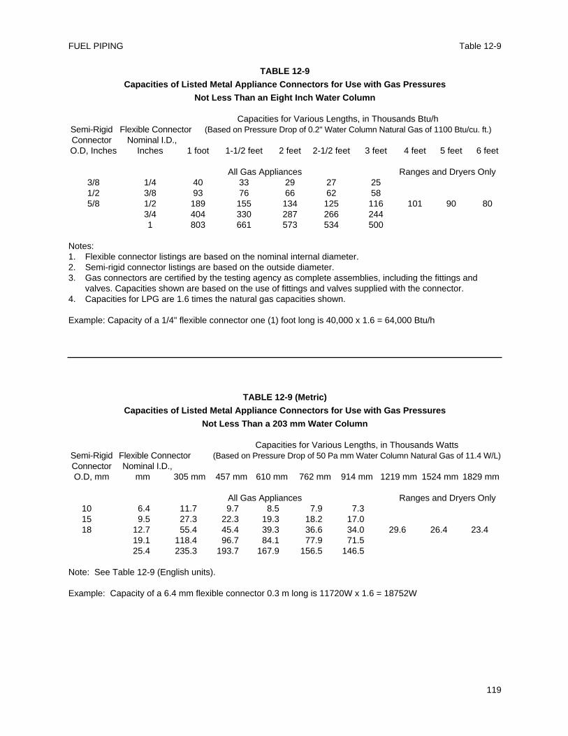
Table 12-9FUEL PIPING
119
TABLE 12-9
Capacities of Listed Metal Appliance Connectors for Use with Gas Pressures
Not Less Than an Eight Inch Water Column
Capacities for Various Lengths, in Thousands Btu/hSemi-Rigid Flexible Connector (Based on Pressure Drop of 0.2" Water Column Natural Gas of 1100 Btu/cu. ft.)Connector Nominal I.D., O.D, Inches Inches 1 foot 1-1/2 feet 2 feet 2-1/2 feet 3 feet 4 feet 5 feet 6 feet
All Gas Appliances Ranges and Dryers Only3/8 1/4 40 33 29 27 251/2 3/8 93 76 66 62 585/8 1/2 189 155 134 125 116 101 90 80
3/4 404 330 287 266 2441 803 661 573 534 500
Notes:1. Flexible connector listings are based on the nominal internal diameter.2. Semi-rigid connector listings are based on the outside diameter.3. Gas connectors are certified by the testing agency as complete assemblies, including the fittings and
valves. Capacities shown are based on the use of fittings and valves supplied with the connector.4. Capacities for LPG are 1.6 times the natural gas capacities shown.
Example: Capacity of a 1/4" flexible connector one (1) foot long is 40,000 x 1.6 = 64,000 Btu/h
TABLE 12-9 (Metric)
Capacities of Listed Metal Appliance Connectors for Use with Gas Pressures
Not Less Than a 203 mm Water Column
Capacities for Various Lengths, in Thousands WattsSemi-Rigid Flexible Connector (Based on Pressure Drop of 50 Pa mm Water Column Natural Gas of 11.4 W/L)Connector Nominal I.D., O.D, mm mm 305 mm 457 mm 610 mm 762 mm 914 mm 1219 mm 1524 mm 1829 mm
All Gas Appliances Ranges and Dryers Only10 6.4 11.7 9.7 8.5 7.9 7.315 9.5 27.3 22.3 19.3 18.2 17.018 12.7 55.4 45.4 39.3 36.6 34.0 29.6 26.4 23.4
19.1 118.4 96.7 84.1 77.9 71.525.4 235.3 193.7 167.9 156.5 146.5
Note: See Table 12-9 (English units).
Example: Capacity of a 6.4 mm flexible connector 0.3 m long is 11720W x 1.6 = 18752W
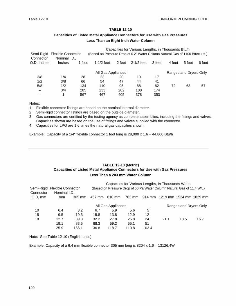
UNIFORM PLUMBING CODETable 12-10
120
TABLE 12-10
Capacities of Listed Metal Appliance Connectors for Use with Gas Pressures
Less Than an Eight Inch Water Column
Capacities for Various Lengths, in Thousands Btu/hSemi-Rigid Flexible Connector (Based on Pressure Drop of 0.2" Water Column Natural Gas of 1100 Btu/cu. ft.)Connector Nominal I.D.,
O.D, Inches Inches 1 foot 1-1/2 feet 2 feet 2-1/2 feet 3 feet 4 feet 5 feet 6 feet
All Gas Appliances Ranges and Dryers Only3/8 1/4 28 23 20 19 171/2 3/8 66 54 47 44 415/8 1/2 134 110 95 88 82 72 63 57– 3/4 285 233 202 188 174– 1 567 467 405 378 353
Notes:1. Flexible connector listings are based on the nominal internal diameter.2. Semi-rigid connector listings are based on the outside diameter.3. Gas connectors are certified by the testing agency as complete assemblies, including the fittings and valves.
Capacities shown are based on the use of fittings and valves supplied with the connector.4. Capacities for LPG are 1.6 times the natural gas capacities shown.
Example: Capacity of a 1/4" flexible connector 1 foot long is 28,000 x 1.6 = 44,800 Btu/h
TABLE 12-10 (Metric)Capacities of Listed Metal Appliance Connectors for Use with Gas Pressures
Less Than a 203 mm Water Column
Capacities for Various Lengths, in Thousands WattsSemi-Rigid Flexible Connector (Based on Pressure Drop of 50 Pa Water Column Natural Gas of 11.4 W/L)Connector Nominal I.D., O.D, mm mm 305 mm 457 mm 610 mm 762 mm 914 mm 1219 mm 1524 mm 1829 mm
All Gas Appliances Ranges and Dryers Only10 6.4 8.2 6.7 5.9 5.6 515 9.5 19.3 15.8 13.8 12.9 1218 12.7 39.3 32.2 27.8 25.8 24 21.1 18.5 16.7
19.1 83.5 68.3 59.2 55.1 5125.9 166.1 136.8 118.7 110.8 103.4
Note: See Table 12-10 (English units).
Example: Capacity of a 6.4 mm flexible connector 305 mm long is 8204 x 1.6 = 13126.4W
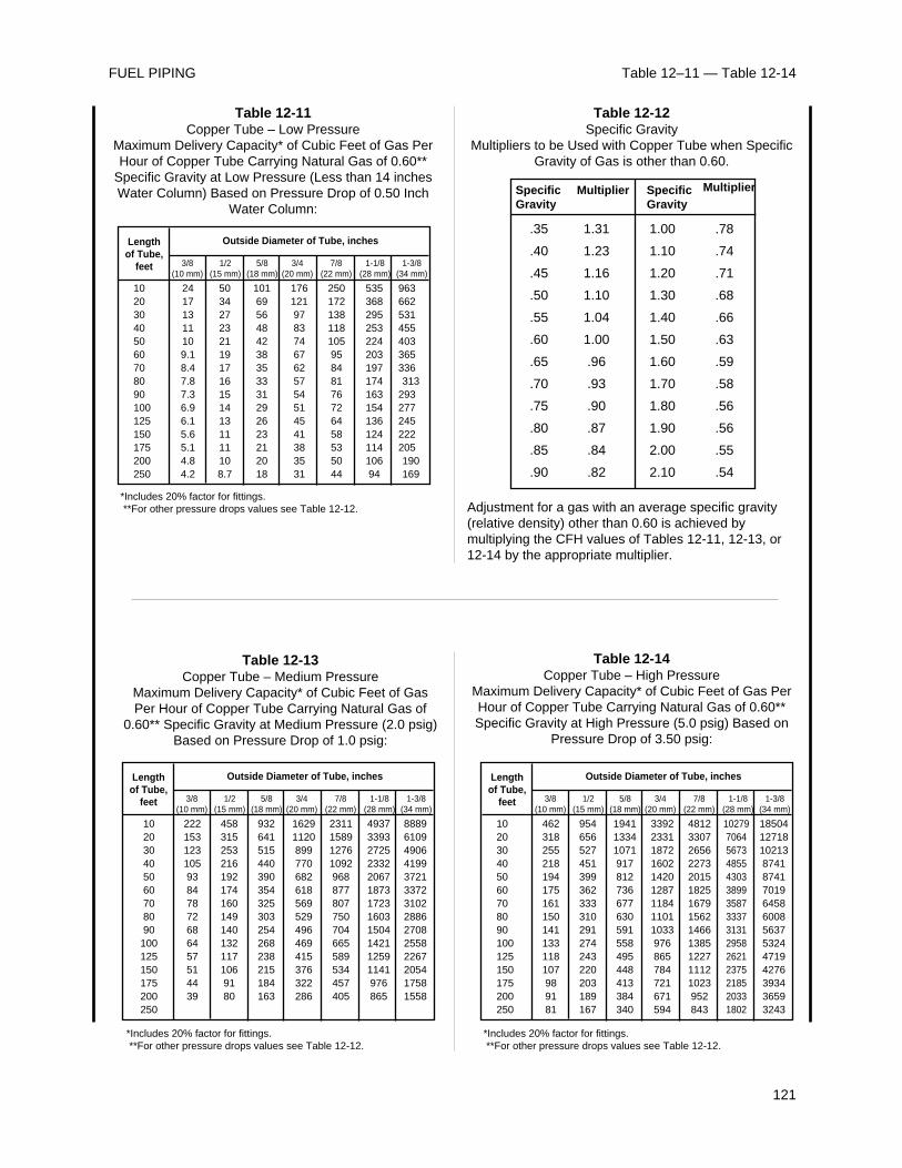
Table 12–11 — Table 12-14FUEL PIPING
121
102030405060708090100125150175200250
24171311109.18.47.87.36.96.15.65.14.84.2
50342723211917161514131111108.7
1016956484238353331292623212018
17612197837467625754514541383531
25017213811810595848176726458535044
53536829525322420319717416315413612411410694
963662531455403365336313
293277245222205190169
3/8(10 mm)
Lengthof Tube,
feet
Outside Diameter of Tube, inches
1/2(15 mm)
5/8(18 mm)
3/4(20 mm)
7/8(22 mm)
1-1/8(28 mm)
1-3/8(34 mm)
Table 12-11Copper Tube – Low Pressure
Maximum Delivery Capacity* of Cubic Feet of Gas PerHour of Copper Tube Carrying Natural Gas of 0.60**
Specific Gravity at Low Pressure (Less than 14 inchesWater Column) Based on Pressure Drop of 0.50 Inch
Water Column:
*Includes 20% factor for fittings.**For other pressure drops values see Table 12-12.
SpecificGravity
SpecificGravity
Multiplier Multiplier
.35
.40
.45
.50
.55
.60
.65
.70
.75
.80
.85
.90
1.31
1.23
1.16
1.10
1.04
1.00
.96
.93
.90
.87
.84
.82
1.00
1.10
1.20
1.30
1.40
1.50
1.60
1.70
1.80
1.90
2.00
2.10
.78
.74
.71
.68
.66
.63
.59
.58
.56
.56
.55
.54
Table 12-12Specific Gravity
Multipliers to be Used with Copper Tube when SpecificGravity of Gas is other than 0.60.
Adjustment for a gas with an average specific gravity(relative density) other than 0.60 is achieved bymultiplying the CFH values of Tables 12-11, 12-13, or12-14 by the appropriate multiplier.
102030405060708090100125150175200250
22215312310593847872686457514439
4583152532161921741601491401321171069180
932641515440390354325303254268238215184163
16291120899770682618569529496469415376322286
2311158912761092968877807750704665589534457405
493733932725233220671873172316031504142112591141976865
88896109490641993721337231022886270825582267205417581558
3/8(10 mm)
Lengthof Tube,
feet
Outside Diameter of Tube, inches
1/2(15 mm)
5/8(18 mm)
3/4(20 mm)
7/8(22 mm)
1-1/8(28 mm)
1-3/8(34 mm)
Table 12-13Copper Tube – Medium Pressure
Maximum Delivery Capacity* of Cubic Feet of GasPer Hour of Copper Tube Carrying Natural Gas of
0.60** Specific Gravity at Medium Pressure (2.0 psig)Based on Pressure Drop of 1.0 psig:
*Includes 20% factor for fittings.**For other pressure drops values see Table 12-12.
102030405060708090100125150175200250
462318255218194175161150141133118107989181
954656527451399362333310291274243220203189167
194113341071917812736677630591558495448413384340
339223311872160214201287118411011033976865784721671594
4812330726562273201518251679156214661385122711121023952843
1027970645673485543033899358733373131295826212375218520331802
18504 1271810213874187417019645860085637532447194276393436593243
3/8(10 mm)
Lengthof Tube,
feet
Outside Diameter of Tube, inches
1/2(15 mm)
5/8(18 mm)
3/4(20 mm)
7/8(22 mm)
1-1/8(28 mm)
1-3/8(34 mm)
Table 12-14Copper Tube – High Pressure
Maximum Delivery Capacity* of Cubic Feet of Gas PerHour of Copper Tube Carrying Natural Gas of 0.60**Specific Gravity at High Pressure (5.0 psig) Based on
Pressure Drop of 3.50 psig:
*Includes 20% factor for fittings.**For other pressure drops values see Table 12-12.

UNIFORM PLUMBING CODE
122
Part I - Special Requirements for Health Care Facilities
1301.0 GeneralThis chapter applies to special fixtures and systemsthat occur in health care facilities and to the specialplumbing requirements in such facilities. Otherplumbing in such facilities shall comply with theother applicable sections of this Code.
1302.0 Medical Gas and Vacuum Piping SystemsThe installation of medical gas and vacuum pipingsystems shall be in accordance with the requirementsof this Chapter and/or the appropriate standardsadopted by the Administrative Authority, foradditional standards see Table 14-1. TheAdministrative Authority shall require evidence ofthe competency of the installers and the certifiers.
1303.0 Protrusions from WallsDrinking fountains, control valves, medical gasstation outlets, vacuum inlet stations, risers, andother devices shall be flushmounted or fully-recessedin corridors and other areas where patients may betransported on a gurney, hospital bed, or wheelchair.
1304.0 Psychiatric Patient RoomsPiping and drain traps in psychiatric patient roomsshall be concealed. Fixtures and fittings shall bevandal-proof.
1305.0 Locations for Ice StorageIce makers or ice storage chests shall be located in anurses station or similarly supervised areas whichare not subject to potential contamination.
1306.0 Sterilizers1306.1 General. The requirements of this sectionapply to sterilizers and bedpan steamers. Suchequipment shall be installed in accordance with thisCode and the manufacturer's installationinstructions.1306.2 Indirect Waste Connections. Waste drainagefrom sterilizers and bedpan steamers shall beindirectly connected to the sanitary drainage systemthrough an air gap in accordance with this Chapterand Chapter 8. Indirect waste piping shall not be lessthan the size of the drain connection on the fixture.Each such indirect waste pipe shall be separatelypiped to a receptor and shall not exceed fifteen (15)
feet (4572 mm) in length. Such receptors shall belocated in the same room as the equipment served.Except for bedpan steamers, such indirect waste pipesshall not require traps. A trap having a minimum sealof three (3) inches (80 mm) shall be provided in theindirect waste pipe for a bedpan steamer.
1307.0 Vapor Vents and Stack for Sterilizers1307.1 General. Where sterilizers have provisionsfor a vapor vent and such a vent is required by theirmanufacturer, a vapor vent shall be extended to theoutdoors above the roof. Sterilizer vapor vents shallbe installed according to the manufacturersinstallation instructions and shall not be connected toany drainage system vent.
1308.0 Aspirators1308.1 See Section 603.4.10 Water Inlets toWater Supplied AspiratorsProvisions for aspirators or other water-suppliedsuction devices shall be installed only with thespecific approval of the Administrative Authority.Where aspirators are used for removing body fluids,they shall include a collecting bottle or similar fluidtrap. Aspirators shall indirectly discharge to thesanitary drainage system through an air gap inaccordance with Chapter 8. The potable watersupply to an aspirator shall be protected by avacuum breaker or equivalent backflow protectiondevice in accordance with Section 603.0.
Part II Medical Gas and Vacuum Systems
1309.0 Scope1309.1 The provisions herein shall apply to theinstallation, testing, and verification of medical gasand vacuum piping for safe use in patient carehospitals, clinics, and other health care facilities.1309.2 The purpose of this chapter is to provideminimum requirements for the installation, testing,and verification of medical gas and medical vacuumsystems, from the point of supply to the user outletsor inlets. These provisions do not cover portablesystems, or cylinder storage requirements.
1310.0 Definitions1310.1 Building Supply – The pipe from the sourceof supply to a building or structure.1310.2 Critical Care Area – An area in a medicalfacility where special care is provided, including
123
CHAPTER 13
HEALTH CARE FACILITIES AND MEDICAL GAS AND VACUUM SYSTEMS
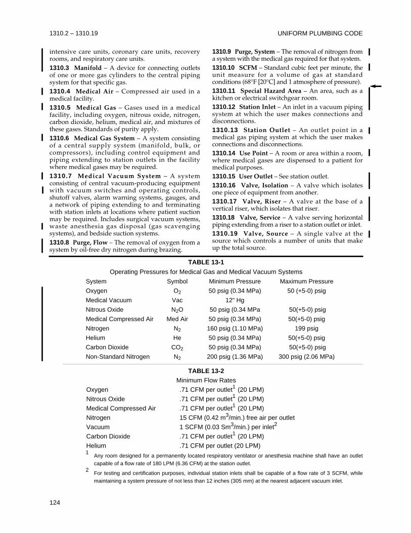
UNIFORM PLUMBING CODE
124
1310.2 – 1310.19
TABLE 13-1
Operating Pressures for Medical Gas and Medical Vacuum Systems
System Symbol Minimum Pressure Maximum Pressure
Oxygen O2 50 psig (0.34 MPa) 50 (+5-0) psig
Medical Vacuum Vac 12" Hg
Nitrous Oxide N2O 50 psig (0.34 MPa 50(+5-0) psig
Medical Compressed Air Med Air 50 psig (0.34 MPa) 50(+5-0) psig
Nitrogen N2 160 psig (1.10 MPa) 199 psig
Helium He 50 psig (0.34 MPa) 50(+5-0) psig
Carbon Dioxide CO2 50 psig (0.34 MPa) 50(+5-0) psig
Non-Standard Nitrogen N2 200 psig (1.36 MPa) 300 psig (2.06 MPa)
TABLE 13-2Minimum Flow Rates
Oxygen .71 CFM per outlet1 (20 LPM)
Nitrous Oxide .71 CFM per outlet1 (20 LPM)
Medical Compressed Air .71 CFM per outlet1 (20 LPM)
Nitrogen 15 CFM (0.42 m3/min.) free air per outlet
Vacuum 1 SCFM (0.03 Sm3/min.) per inlet2
Carbon Dioxide .71 CFM per outlet1 (20 LPM)
Helium .71 CFM per outlet (20 LPM) 1
Any room designed for a permanently located respiratory ventilator or anesthesia machine shall have an outletcapable of a flow rate of 180 LPM (6.36 CFM) at the station outlet.
2For testing and certification purposes, individual station inlets shall be capable of a flow rate of 3 SCFM, whilemaintaining a system pressure of not less than 12 inches (305 mm) at the nearest adjacent vacuum inlet.
intensive care units, coronary care units, recoveryrooms, and respiratory care units.1310.3 Manifold – A device for connecting outletsof one or more gas cylinders to the central pipingsystem for that specific gas.1310.4 Medical Air – Compressed air used in amedical facility.1310.5 Medical Gas – Gases used in a medicalfacility, including oxygen, nitrous oxide, nitrogen,carbon dioxide, helium, medical air, and mixtures ofthese gases. Standards of purity apply.1310.6 Medical Gas System – A system consistingof a central supply system (manifold, bulk, orcompressors), including control equipment andpiping extending to station outlets in the facilitywhere medical gases may be required.1310.7 Medical Vacuum System – A systemconsisting of central vacuum-producing equipmentwith vacuum switches and operating controls,shutoff valves, alarm warning systems, gauges, anda network of piping extending to and terminatingwith station inlets at locations where patient suctionmay be required. Includes surgical vacuum systems,waste anesthesia gas disposal (gas scavengingsystems), and bedside suction systems.1310.8 Purge, Flow – The removal of oxygen from asystem by oil-free dry nitrogen during brazing.
1310.9 Purge, System – The removal of nitrogen froma system with the medical gas required for that system.1310.10 SCFM – Standard cubic feet per minute, theunit measure for a volume of gas at standardconditions (68°F [20°C] and 1 atmosphere of pressure).1310.11 Special Hazard Area – An area, such as akitchen or electrical switchgear room.1310.12 Station Inlet – An inlet in a vacuum pipingsystem at which the user makes connections anddisconnections.1310.13 Station Outlet – An outlet point in amedical gas piping system at which the user makesconnections and disconnections.1310.14 Use Point – A room or area within a room,where medical gases are dispensed to a patient formedical purposes. 1310.15 User Outlet – See station outlet.1310.16 Valve, Isolation – A valve which isolatesone piece of equipment from another.1310.17 Valve, Riser – A valve at the base of avertical riser, which isolates that riser.1310.18 Valve, Service – A valve serving horizontalpiping extending from a riser to a station outlet or inlet.1310.19 Valve, Source – A single valve at thesource which controls a number of units that makeup the total source.
1310.20 Valve, Zone – A valve which controls thegas or vacuum service to a particular area.
1311.0 General Requirements1311.1 Medical gas and medical vacuum systemsshall be designed and installed in accordance withthe requirements of this chapter and the installationrequirements of this Code. Systems shall be designedto provide for an adequate and safe supply ofmedical gas and medical vacuum from the point ofsupply to the user outlet or inlet. Installation andtesting of medical gas and medical vacuum systemsshall be inspected by the Administrative Authority.Items not covered in this chapter shall be installed inaccordance with the appropriate standardsreferenced in Table 14-1 and the approval of theAdministrative Authority.1311.2 Certification of medical gas and medicalvacuum systems shall conform to the requirementsof this Code and the Administrative Authority.1311.3 The Administrative Authority shall requireevidence of the competency of the installers and theverifiers.1311.4 All medical gas and medical vacuumsystems shall be supplied from a source consisting ofat least two units – primary and secondary, e.g., amanifold consisting of two cylinder banks with atleast two cylinders in each bank, minimum of two aircompressors, or minimum of two vacuum pumps.However, two supply pipelines are not required.
1312.0 Plan Review1312.1 Before any medical gas or medical vacuumsystem is installed or altered in any hospital, medicalfacility, or clinic, duplicate plans and specifications shallbe filed with the Administrative Authority. Approval ofthe plans shall be obtained prior to the issuance of anypermit by the Administrative Authority.1312.2 Plans and specifications shall show, in detail:
1312.2.1 Plot plan of the site, drawn to scale,indicating the location of existing or newcylinder storage areas, property lines,driveways, and existing or proposed buildings.1312.2.2 Piping layout of the proposed pipingsystem or alteration, including all alarms, valves,origin of gases and user outlets/inlets. Thedemand and loading of any piping, existing orfuture, shall also be indicated.1312.2.3 Complete specification of materials.
1312.3 Plans and specifications submitted to theAdministrative Authority shall be of sufficient clarityto indicate the nature and extent of the workproposed and shall show in detail that such workwill conform to the provisions of this Code.1312.4 A record of as-built plans and valveidentification records shall remain on the site at all times.
1313.0 System Performance1313.1 Required Operating Pressures . Allmedical gas and medical vacuum systems shall becapable of delivering service in the pressure rangeslisted in Table 13-1.1313.2 Minimum Flow Rates. All medical gas andmedical vacuum systems shall be capable ofsupplying the flow rates listed in Table 13-2.1313.3 Minimum Station Outlets/Inlets. Stationoutlets and inlets for medical gas and medical vacuumsystems shall be provided as listed in Table 13-3.
1314.0 System Sizing1314.1 All medical gas system sizing should be theobligation of the mechanical engineer and not anindividual using this code.
1315.0 Required Pipe Sizing1315.1 Where the maximum demand for eachmedical gas or vacuum system nor the maximumlength of piping between the source equipment andthe most distant station outlet/inlet does not exceedthe table, the size of each section of the system shall bedetermined by means of Table 13-4 and 13-6. Systemsbeyond the range of Table 13-6 shall be sized by meansof the methods set forth in 1315.3 of this section.1315.2 To determine the size of each section of pipein any system within the range of Table 13-6,proceed as follows:
1315.2.1 Measure the length of the pipe fromthe source equipment location to the mostremote inlet/outlet terminal on the system.1315.2.2 In Table 13-6, select the columnshowing that distance, or the next longer distanceif the table does not give the exact length.1315.2.3 Starting at the most remote outlet, findin the vertical column just selected, the medicalgas or vacuum demand for that inlet/outlet. Ifthe exact figure of demand is not shown, choosethe next larger figure below in the column.1315.2.4 Opposite this demand figure, in thefirst column at the left in Table 13-6 will befound the correct size of pipe.1315.2.5 Using this same vertical column,proceed in a similar manner for each section ofpipe serving this inlet/outlet. For each section ofpipe, determine the total gas or vacuum demandsupplied by the section, using Table 13-4.1315.2.6 Size each section of branch piping notpreviously sized by measuring the distance fromthe source equipment location to the mostremote inlet/outlet in that branch and follow theprocedures of 1315.2.2, 1315.2.3, 1315.2.4, and 1315.2.5Note: Size branch piping in the order of thedistance from the source location, beginning withthe most distant outlet not previously sized.
MEDICAL GAS SYSTEMS 1310.20 – 1315.2
125
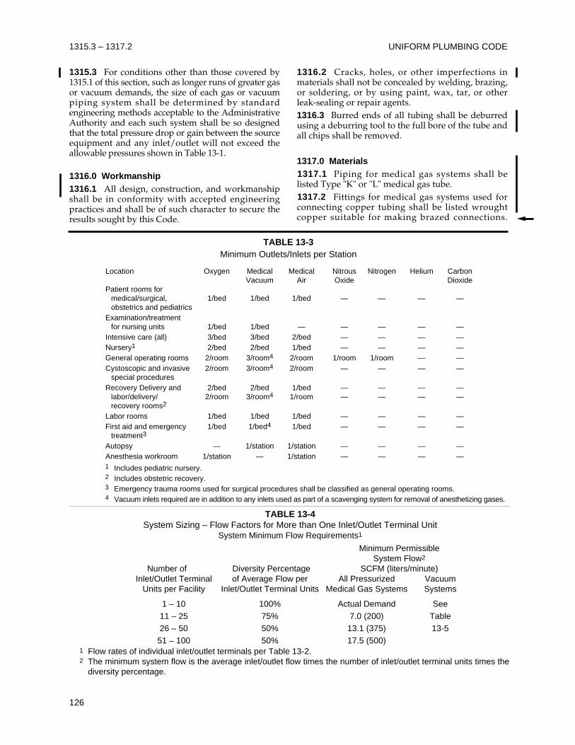
UNIFORM PLUMBING CODE
126
1315.3 – 1317.2
1315.3 For conditions other than those covered by1315.1 of this section, such as longer runs of greater gasor vacuum demands, the size of each gas or vacuumpiping system shall be determined by standardengineering methods acceptable to the AdministrativeAuthority and each such system shall be so designedthat the total pressure drop or gain between the sourceequipment and any inlet/outlet will not exceed theallowable pressures shown in Table 13-1.
1316.0 Workmanship1316.1 All design, construction, and workmanshipshall be in conformity with accepted engineeringpractices and shall be of such character to secure theresults sought by this Code.
1316.2 Cracks, holes, or other imperfections inmaterials shall not be concealed by welding, brazing,or soldering, or by using paint, wax, tar, or otherleak-sealing or repair agents.1316.3 Burred ends of all tubing shall be deburredusing a deburring tool to the full bore of the tube andall chips shall be removed.
1317.0 Materials1317.1 Piping for medical gas systems shall belisted Type "K" or "L" medical gas tube.1317.2 Fittings for medical gas systems used forconnecting copper tubing shall be listed wroughtcopper suitable for making brazed connections.
TABLE 13-3Minimum Outlets/Inlets per Station
Location Oxygen Medical Medical Nitrous Nitrogen Helium CarbonVacuum Air Oxide Dioxide
Patient rooms formedical/surgical, 1/bed 1/bed 1/bed — — — —obstetrics and pediatrics
Examination/treatment for nursing units 1/bed 1/bed — — — — —
Intensive care (all) 3/bed 3/bed 2/bed — — — —Nursery1 2/bed 2/bed 1/bed — — — —General operating rooms 2/room 3/room4 2/room 1/room 1/room — —Cystoscopic and invasive 2/room 3/room4 2/room — — — —
special proceduresRecovery Delivery and 2/bed 2/bed 1/bed — — — —
labor/delivery/ 2/room 3/room4 1/room — — — —recovery rooms2
Labor rooms 1/bed 1/bed 1/bed — — — —First aid and emergency 1/bed 1/bed4 1/bed — — — —
treatment3
Autopsy — 1/station 1/station — — — —Anesthesia workroom 1/station — 1/station — — — —1 Includes pediatric nursery.2 Includes obstetric recovery.3 Emergency trauma rooms used for surgical procedures shall be classified as general operating rooms.4 Vacuum inlets required are in addition to any inlets used as part of a scavenging system for removal of anesthetizing gases.
TABLE 13-4System Sizing – Flow Factors for More than One Inlet/Outlet Terminal Unit
System Minimum Flow Requirements1
Minimum PermissibleSystem Flow2
Number of Diversity Percentage SCFM (liters/minute)Inlet/Outlet Terminal of Average Flow per All Pressurized Vacuum
Units per Facility Inlet/Outlet Terminal Units Medical Gas Systems Systems
1 – 10 100% Actual Demand See11 – 25 75% 7.0 (200) Table26 – 50 50% 13.1 (375) 13-551 – 100 50% 17.5 (500)
1 Flow rates of individual inlet/outlet terminals per Table 13-2.2 The minimum system flow is the average inlet/outlet flow times the number of inlet/outlet terminal units times the
diversity percentage.
MEDICAL GAS SYSTEMS 1317.2 – 1320.1
127
Valves, manifolds, terminal connections, and othersuch devices installed in medical gas systems shallbe bronze, brass, or of other materials that meet therequirements of Section 301.0.1317.3 Piping for medical gas systems shall besuitable for and compatible with oxygen service.Tubing shall be cleaned and delivered to the job site,and plugged or capped. Fittings, valves, and otherdevices shall be cleaned, sealed, and marked asdescribed in Section 1318.0. The installer shallfurnish documentation certifying that all installedpiping materials comply with these requirements.1317.4 Piping for medical vacuum systems shall belisted seamless Type K or L copper tubing, or otherapproved or listed materials. For vacuum systems,the provision in Section 1317.3 for oxygencompatibility and cleanliness does not apply. 1317.5 Fittings for medical vacuum systems shall bethe same as described in Section 1317.2 if brazed. Ifsoft soldered, brass or bronze fittings are permitted.1317.6 All ball valves used in medical gas andmedical vacuum systems shall be fullway.1317.7 Piping for medical nitrogen systems inexcess of 200 psig (1.36 MPa gauge) and notexceeding 300 psig (2.07 MPa gauge) shall be type“K” copper.
1318.0 Cleaning1318.1 Prior to delivery to the installation site,piping, valves, fittings and other components ofmedical gas systems shall have been internallycleaned to remove oil, grease, and other oxidizablematerials as if for oxygen service. 1318.2 On-site recleaning shall be limited torecleaning joints that have become contaminatedimmediately prior to assembly.
1319.0 Installation of Piping1319.1 All tubing shall be cut square using a clean,sharp tubing cutter which is free from grease, oil, orother lubricants not suitable for oxygen service, andshall be deburred to the full inner diameter of thetube.1319.2 Copper tubing ends and fittings shall becleaned with an non-scratching pad to ensure properjoining when brazed.1319.3 Threads for pipeline accessories shall bestandard tapered pipe threads. Threaded joints inpiping accessories shall be applied withpolytetrafluorethylene such as (teflon™) tape or withother non-oil-based thread sealant approved foroxygen service. Sealant shall be applied to the malethreads only. All excess tape or sealant shall beremoved.1319.4 No burrs, copper dust, oil, thread jointcompound, or other contaminates shall be
introduced into the piping at any time during theinstallation process.1319.5 All installations of medical gas and medicalvacuum piping, including buried piping, shall beadequately protected against frost, freezing,corrosion, and physical damage. Buried piping shallbe buried at a sufficient depth to protect the pipingfrom excessive stresses. The minimum backfilledcover above the top of buried piping outside ofbuilding shall be thirty-six (36) inches (91.4 cm),except that the minimum cover shall be permitted tobe reduced to eighteen (18) inches (45.7 cm) wherephysical damage to the piping is not likely to occur.Trenches shall be excavated so that the pipe has afirm, substantially continuous bearing on the bottomof the trench. Underground piping shall be installedin a continuous split enclosure to protect the pipefrom damage while backfilling. Backfill shall be cleanand compacted so as to protect and uniformlysupport the piping. A continuous tape or markerplaced immediately above the enclosure shall clearlyidentify the pipeline by specific name. In addition, acontinuous warning means shall be provided abovethe pipeline at approximately one-half the depth ofbury. Exposed piping shall be protected againstphysical damage from portable equipment such ascarts, stretchers, and trucks.1319.6 Medical gas and medical vacuum pipingshall be installed to protect against physical damage.Openings for piping in concealed spaces shall be fire-stopped, with the construction having a fireresistance equal to or greater than the originalconstruction. Medical gas and medical vacuum risersinstalled in pipe shafts shall be protected againstphysical damage, effects of excessive heat, corrosion,and contact with oil. Medical gas and medicalvacuum risers shall not be located in elevator shafts.1319.7 Medical gas and medical vacuum pipingshall not be installed in kitchens or electricalswitchgear rooms.1319.8 Approved or listed flexible connectors maybe used where required for flexibility. Flexibleconnectors shall not penetrate walls, floors, ceilings,or partitions and shall be no longer than necessary.Flexible connectors, metallic or nonmetallic, shallhave a minimum burst pressure of 1000 psig (6900kPa gauge).1319.9 Piping Support and Bracing. Piping andother components used in medical gas and vacuumsystems shall be adequately supported and braced asrequired elsewhere in this Code. Seismicconsiderations shall conform to the requirements ofthis Code and the Administrative Authority.
1320.0 Joints1320.1 Copper-to-copper joints shall be brazedwithout flux using a copper-phosphorus or copper-phosphorus-silver brazing filler metal (BCuP series).
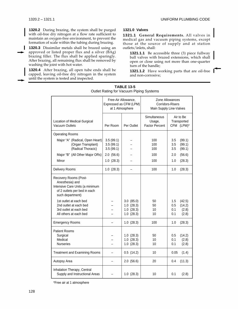
UNIFORM PLUMBING CODE
128
1320.2 – 1321.1
1320.2 During brazing, the system shall be purgedwith oil-free dry nitrogen at a flow rate sufficient tomaintain an oxygen-free environment, to prevent theformation of scale within the tubing during brazing.1320.3 Dissimilar metals shall be brazed using anapproved or listed proper flux and a silver (BAg)brazing filler. The flux shall be applied sparingly.After brazing, all remaining flux shall be removed bywashing the joint with hot water.1320.4 After brazing, all open tube ends shall becapped, leaving oil-free dry nitrogen in the systemuntil the system is tested and inspected.
1321.0 Valves1321.1 General Requirements. All valves inmedical gas and vacuum piping systems, exceptthose at the source of supply and at stationoutlets/inlets, shall:
1321.1.1 Be accessible three (3) piece fullwayball valves with brazed extensions, which shallopen or close using not more than one-quarterturn of the handle;1321.1.2 Have working parts that are oil-freeand non-corrosive;
TABLE 13-5Outlet Rating for Vacuum Piping Systems
Free-Air Allowance, Zone AllowancesExpressed as CFM (LPM) Corridors-Risers
at 1 Atmosphere Main Supply Line-Valves
Simultaneous Air to BeLocation of Medical-Surgical Usage, TransportedVacuum Outlets Per Room Per Outlet Factor Percent CFM (LPM)*
Operating Rooms
Major “A” (Radical, Open Heart) 3.5 (99.1) – 100 3.5 (99.1)(Organ Transplant) 3.5 (99.1) – 100 3.5 (99.1)(Radical Thoracic) 3.5 (99.1) – 100 3.5 (99.1)
Major “B” (All Other Major ORs) 2.0 (56.6) – 100 2.0 (56.6)
Minor 1.0 (28.3) – 100 1.0 (28.3)
Delivery Rooms 1.0 (28.3) – 100 1.0 (28.3)
Recovery Rooms (Post-Anesthesia) and
Intensive Care Units (a minimum of 2 outlets per bed in each such department)
1st outlet at each bed – 3.0 (85.0) 50 1.5 (42.5)2nd outlet at each bed – 1.0 (28.3) 50 0.5 (14.2)3rd outlet at each bed – 1.0 (28.3) 10 0.1 (2.8)All others at each bed – 1.0 (28.3) 10 0.1 (2.8)
Emergency Rooms – 1.0 (28.3) 100 1.0 (28.3)
Patient RoomsSurgical – 1.0 (28.3) 50 0.5 (14.2)Medical – 1.0 (28.3) 10 0.1 (2.8)Nurseries – 1.0 (28.3) 10 0.1 (2.8)
Treatment and Examining Rooms – 0.5 (14.2) 10 0.05 (1.4)
Autopsy Area – 2.0 (56.6) 20 0.4 (11.3)
Inhalation Therapy, Central Supply and Instructional Areas – 1.0 (28.3) 10 0.1 (2.8)
*Free air at 1 atmosphere
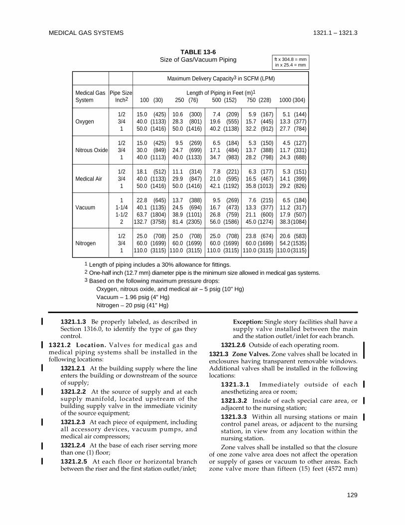
MEDICAL GAS SYSTEMS 1321.1 – 1321.3
129
1321.1.3 Be properly labeled, as described inSection 1316.0, to identify the type of gas theycontrol.
1321.2 Location. Valves for medical gas andmedical piping systems shall be installed in thefollowing locations:
1321.2.1 At the building supply where the lineenters the building or downstream of the sourceof supply;1321.2.2 At the source of supply and at eachsupply manifold, located upstream of thebuilding supply valve in the immediate vicinityof the source equipment;1321.2.3 At each piece of equipment, includingall accessory devices, vacuum pumps, andmedical air compressors;1321.2.4 At the base of each riser serving morethan one (1) floor;1321.2.5 At each floor or horizontal branchbetween the riser and the first station outlet/inlet;
Exception: Single story facilities shall have asupply valve installed between the mainand the station outlet/inlet for each branch.
1321.2.6 Outside of each operating room.1321.3 Zone Valves. Zone valves shall be located inenclosures having transparent removable windows.Additional valves shall be installed in the followinglocations:
1321.3.1 Immediately outside of eachanesthetizing area or room;1321.3.2 Inside of each special care area, oradjacent to the nursing station;1321.3.3 Within all nursing stations or maincontrol panel areas, or adjacent to the nursingstation, in view from any location within thenursing station.Zone valves shall be installed so that the closure
of one zone valve area does not affect the operationor supply of gases or vacuum to other areas. Eachzone valve more than fifteen (15) feet (4572 mm)
TABLE 13-6Size of Gas/Vacuum Piping
Maximum Delivery Capacity3 in SCFM (LPM)
Medical Gas Pipe Size Length of Piping in Feet (m)1System Inch2 100 (30) 250 (76) 500 (152) 750 (228) 1000 (304)
1/2 15.0 (425) 10.6 (300) 7.4 (209) 5.9 (167) 5.1 (144)Oxygen 3/4 40.0 (1133) 28.3 (801) 19.6 (555) 15.7 (445) 13.3 (377)
1 50.0 (1416) 50.0 (1416) 40.2 (1138) 32.2 (912) 27.7 (784)
1/2 15.0 (425) 9.5 (269) 6.5 (184) 5.3 (150) 4.5 (127)Nitrous Oxide 3/4 30.0 (849) 24.7 (699) 17.1 (484) 13.7 (388) 11.7 (331)
1 40.0 (1113) 40.0 (1133) 34.7 (983) 28.2 (798) 24.3 (688)
1/2 18.1 (512) 11.1 (314) 7.8 (221) 6.3 (177) 5.3 (151)Medical Air 3/4 40.0 (1133) 29.9 (847) 21.0 (595) 16.5 (467) 14.1 (399)
1 50.0 (1416) 50.0 (1416) 42.1 (1192) 35.8 (1013) 29.2 (826)
1 22.8 (645) 13.7 (388) 9.5 (269) 7.6 (215) 6.5 (184)Vacuum 1-1/4 40.1 (1135) 24.5 (694) 16.7 (473) 13.3 (377) 11.2 (317)
1-1/2 63.7 (1804) 38.9 (1101) 26.8 (759) 21.1 (600) 17.9 (507)2 132.7 (3758) 81.4 (2305) 56.0 (1586) 45.0 (1274) 38.3 (1084)
1/2 25.0 (708) 25.0 (708) 25.0 (708) 23.8 (674) 20.6 (583)Nitrogen 3/4 60.0 (1699) 60.0 (1699) 60.0 (1699) 60.0 (1699) 54.2 (1535)
1 110.0 (3115) 110.0 (3115) 110.0 (3115) 110.0 (3115) 110.0 (3115)
1 Length of piping includes a 30% allowance for fittings.2 One-half inch (12.7 mm) diameter pipe is the minimum size allowed in medical gas systems.3 Based on the following maximum pressure drops:
Oxygen, nitrous oxide, and medical air – 5 psig (10" Hg)Vacuum – 1.96 psig (4" Hg)Nitrogen – 20 psig (41" Hg)
ft x 304.8 = mmin x 25.4 = mm
from a station outlet shall have a service isolationvalve installed immediately adjacent to the riser forthat branch.
Exception: Anesthetizing suites and special careareas shall be supplied by lateral branch lines offthe risers with no other intervening shutoffvalves.
1321.4 Enclosures. Where valves are concealed inany enclosure, the door or entry to the enclosureshall be identified and color coded with the type ofgas service installed, as described in Section 1324.0.Enclosures shall be of sufficient size to permit valveoperation. Valve handles in the “off” position shallprevent closure of the access panel or door.
1322.0 Pressure Regulating Equipment1322.1 Pressure regulating equipment shall beinstalled in the supply main upstream of the finalline-pressure relief valve. Each central supply systemshall have a pressure relief valve set at fifty (50)percent above normal line pressure, installeddownstream of the pressure regulator and upstreamof any shutoff valve. All pressure relief valves shallbe constructed of brass or bronze and closeautomatically when excess pressure has beenreleased.1322.2 Pressure Gauges. A pressure gauge shall beinstalled in the main line adjacent to the alarmactuating switch. Gauges shall be labeled asdescribed in Section 1324.0, and shall be readilyvisible at all times from a standing position.1322.3 A pressure relief valve shall not be isolatedfrom its intended use by any valve.
1323.0 Station Outlets/InletsStation outlets and inlets shall be installed in strictaccordance with the manufacturer’s instructions.After installation of the piping, but beforeinstallation of the station outlets/inlets and othermedical gas and medical vacuum systemcomponents (e.g., pressure actuating switches foralarms, manifolds, pressure gauges, or pressurerelief valves), system lines shall be purged by meansof oil-free dry nitrogen.
1324.0 Marking and Identification1324.1 All medical gas piping, valves, andmanifolds shall have permanent labels bearing thename of the gas they carry or control. 1324.2 The labeling shall be by means of metal tags,stenciling, stamping, or adhesive markers, and shallbe visible.1324.3 Each pipe shall bear a label at intervals notto exceed twenty (20) feet (6096 mm), at least once ineach room, before and after barriers, behind accessdoors, and at outlets and inlets. Vertical risers shall
be marked at every floor. The label shall:1324.3.1 Have lettering at least three-eighths(3/8) (9.5 mm) high;1324.3.2 Be applied with the lettering parallelto the axis of the pipe.
1324.4 The labels shall be in the following colors:Gas Marking ColorsMedical Air Yellow background with black lettersNitrogen Black background with white lettersNitrous Oxide Blue background with white lettersOxygen Green background with white lettersVacuum White background with black lettersHelium Brown background with white lettersCarbon Dioxide Gray background with black or white
letters1324.5 Valve Identification
1324.5.1 All valves and manifolds shall beidentified by means of a metal tag, stamped withthe name of the gas it conveys or controls andsecurely attached to the valve or manifold.1324.5.2 Each valve installed in a medical gaspiping system shall be marked with a symbol,number, or description for area of control. Arecord shall be made listing the rooms/areacontrolled by each valve for each gas, and shallremain with the facility owner.1324.5.3 Where a valve is accessible, its locationshall be permanently identified with thefollowing: “(Type Gas) Shutoff Valve for (Locationor Zone)”. The identification shall be lettered andcolor coded as described in this Section.
1325.0 Alarms1325.1 An alarm system, (Master), with both anaudible and non-cancelable visual signal shall beinstalled in each medical gas and medical vacuumsystem. This alarm system shall have two (2) separatesignal panels located in areas where at least one (1) ofthe two (2) is always under continuous surveillance.1325.2 The master alarm shall indicate any changein pressure above or below the normal operatingpressure ranges listed in Table 13-1, change from theprimary to secondary supply, any failure of theemergency reserve to operate, and low pressure inthe reserve source.1325.3 Functioning of all alarm components shall beverified in accordance with testing and monitoringrequirements of the manufacturer and theAdministrative Authority.
1326.0 Medical Air System1326.1 The medical air system shall consist of aminimum of two (2) units working separately. Ifonly two (2) units are installed, only one shall
UNIFORM PLUMBING CODE
130
1321.3 – 1326.1
normally operate at a time. If more than two unitsare installed, the compressors shall maintain thepeak calculated load when the largest unit is out ofservice to provide a continuous service. The abovecomponents shall be installed with a receiver tankand piped to the system. The assembly shall beequipped with isolation valves so that eachcompressor unit and receiver can be isolated andserviced without disrupting service. 1326.2 The intake to medical air compressors shallbe located outdoors above roof level a minimumdistance of ten (10) feet (3048 mm) from any door,window, other intake, or opening in the building,and a minimum distance of twenty (20) feet (6096 mm) above the ground. 1326.3 Each medical air compressor shall have aisolation valve installed so that shutting off or failureof the largest unit will not affect the operation ofother unit(s).1326.4 Drains shall be installed on dryers,aftercoolers, separators, and receivers.1326.5 Air intakes for separate medical aircompressors may be joined together to one commonintake and shall be located in a position where thereis no contamination from any other system. Airintakes shall be turned down and screened.1326.6 Medical air compressors shall be installed ina well lit, ventilated, and clean location, and shall beaccessible. The location shall be provided withdrainage facilities. The medical air compressor areashall be located separately from medical gas cylindersystem sources, and shall be readily accessible formaintenance.
1327.0 Medical Vacuum Pump System1327.1 The medical vacuum pump system shallconsist of a minimum two units working separatelyto provide a continuous service. The abovecomponents shall be installed with a receiver tankand piped to the system. If only two units areinstalled, only one shall normally operate at a time. Ifmore than two units are installed, the vacuumpumps shall maintain the peak calculated load whenthe largest pump is out of service. The assembly shallbe equipped with isolation valves so that each pumpunit and receiver can be isolated and servicedwithout disrupting service. The discharge of thevacuum system shall be located away from any airintake.1327.2 The exhaust from the vacuum pumps shallbe piped to the outside with the end turned downand screened. The exhaust terminal shall be aminimum horizontal distance of thirty (30) feet (9144mm) from any door or window and fifty (50) feet(15240 mm) horizontal distance from any mechanicalair intake.
1327.3 Each vacuum pump shall have a isolationvalve installed so that shutting off or failure of thelargest unit will not affect the operation of otherunit(s). The system shall maintain peak calculatedload when the largest unit is out of service.1327.4 Drains shall be installed and terminate in anapproved location.1327.5 The vacuum plant shall be installed in a welllit, ventilated and clean location with ampleaccessibility. The location shall be provided withdrainage facilities. The vacuum plant, when installedas a source, shall be located separately from othermedical vacuum system sources, and shall be readilyaccessible for maintenance.
1328.0 Future ExtensionsWhere provision is made for future extensions ofexisting medical gas or vacuum systems, the pipesshall be valved and fitted with caps.
1329.0 Testing1329.1 Advance Notice. Advance notice shall berequired as in Section 1330.2.1329.2 Responsibility. The equipment, material,and labor necessary for inspection and testing shallbe furnished by the permit holder or by the personwho is requesting the inspection.1329.3 Media. The piping of medical gas andmedical vacuum systems shall be tested with oil-freedry nitrogen.1329.4 Testing. Tests shall be conducted in thepresence of the Administrative Authority or a dulyappointed representative.1329.5 Retesting. If the Administrative Authorityfinds that the work will not pass the tests, necessarycorrections shall be made and the work shall then beresubmitted for test or inspection.1329.6 Rough Testing. Before attachment of systemcomponents (e.g., pressure-actuating switches foralarms, manifolds, pressure gauges, or pressurerelief valves), but after installation of the stationoutlets and inlets, with test caps in place, eachsection of the piping system shall be subjected to atest pressure of one and a half (1-1/2) times workingpressure or a minimum of one hundred-fifty (150)psig (1.03 MPa gauge) with oil-free dry nitrogen.This test pressure shall be maintained until each jointhas been examined for leakage by means of soapywater or other equally effective means of leakdetection safe for use with oxygen. Any leaks shallbe located, repaired, and retested, except no jointshall be repaired more than once.1329.7 Final Testing. For each medical gas andmedical vacuum system, the completely assembledstation outlets/inlets and all other system componentsshall be installed prior to testing. Each piping system
MEDICAL GAS SYSTEMS
131
1326.1 – 1329.7
shall be subjected to a twenty-four (24)-hour standingpressure test at twenty (20) percent above the normaloperation line pressure. The test gas used shall be oil-free dry nitrogen. The source valve and all outletsshall be closed and the test gas shall be disconnected.The piping system shall remain leak-free for twenty-four (24) hours. The only allowable pressure changesduring the twenty-four (24)-hour test period shall bethose caused by variations in the ambient temperaturearound the piping system. Any leaks shall be located,repaired, and retested, except no joint shall berepaired more than once.
1330.0 Inspection1330.1 Scope. All new medical gas and vacuumpiping systems, portions of existing systems whichmay be affected by new work, and changes in existingsystems, shall be inspected by the AdministrativeAuthority to ensure compliance with the requirementsof this Code, and to ensure that the installation andconstruction of the medical gas and vacuum systemsare in accordance with approved plans. 1330.2 Advance Notice. It shall be the duty of theperson doing the work authorized by the permit tonotify the Administrative Authority, orally or inwriting, that said work is ready for inspection. Suchnotification shall be given not less than twenty-four(24) hours before the work is to be inspected.1330.3 Responsibility. It shall be the duty of theholder of the permit to determine that the work willstand the test prescribed, before giving the notification.1330.4 Testing. Tests shall be conducted in thepresence of the Administrative Authority or a dulyappointed representative.1330.5 Retesting. If the Administrative Authorityfinds that the work will not pass the tests, necessarycorrections shall be made and the work shall then beresubmitted for test or inspection.1330.6 Corrections. Notices of correction orviolation shall be written by the AdministrativeAuthority and may be posted at the site of the workor mailed or delivered to the permittee or anauthorized representative. Refusal or failure tocomply with any such notice or order within ten (10)days of receipt thereof, shall be considered aviolation of this Code, and shall be subject to thepenalties set forth elsewhere in this Code forviolations.1330.7 Approval. Upon the satisfactory completionof all tests and certification of the medical gas andmedical vacuum systems, a certificate of approvalshall be issued by the Administrative Authority tothe permittee.1330.8 Covering or Use. No medical gas or medicalvacuum system or part thereof, shall be covered,concealed or put into use until it has been tested,inspected, and accepted as required in this Code.
1330.9 Uncovering. Any medical gas and vacuumsystem or part thereof which is covered or concealedbefore being tested and inspected as required in thisCode, shall be uncovered for inspection, after noticeto uncover the work has been issued to the permitteeor his authorized representative by theAdministrative Authority.
1331.0 System Certification1331.1 Prior to any medical gas system being placedin service, each and every system shall be certified,as described in Section 1331.2. This certification shallbe accomplished by qualified independent thirdparty verification agency which is approved by theAdministrative Authority.1331.2 Certification tests, verified and attested to bythe certification agency, shall include the following:
1331.2.1 Verifying compliance with theinstallation requirements;1331.2.2 Testing and checking for leakage,correct zoning, and identification of controlvalves;1331.2.3 Checking for identification andlabeling of pipelines, station outlets, and controlvalves;1331.2.4 Testing for cross-connection, flow rate,system pressure drop, and system performance;1331.2.5 Functional testing of pressure reliefvalves and safety valves;1331.2.6 Functional testing of all sources ofsupply;1331.2.7 Functional testing of alarm systems,including accuracy of system components;1331.2.8 Purge flushing of system and fillingwith specific source gas;1331.2.9 Testing for purity and cleanliness ofsource gases;1331.2.10 Testing for specific gas identity ateach station outlet.
1331.3 A report which includes at least the specificitems mentioned in Section 1331.2 shall be deliveredto the Administrative Authority prior to acceptanceof the system.
UNIFORM PLUMBING CODE
132
1329.7 – 1331.3
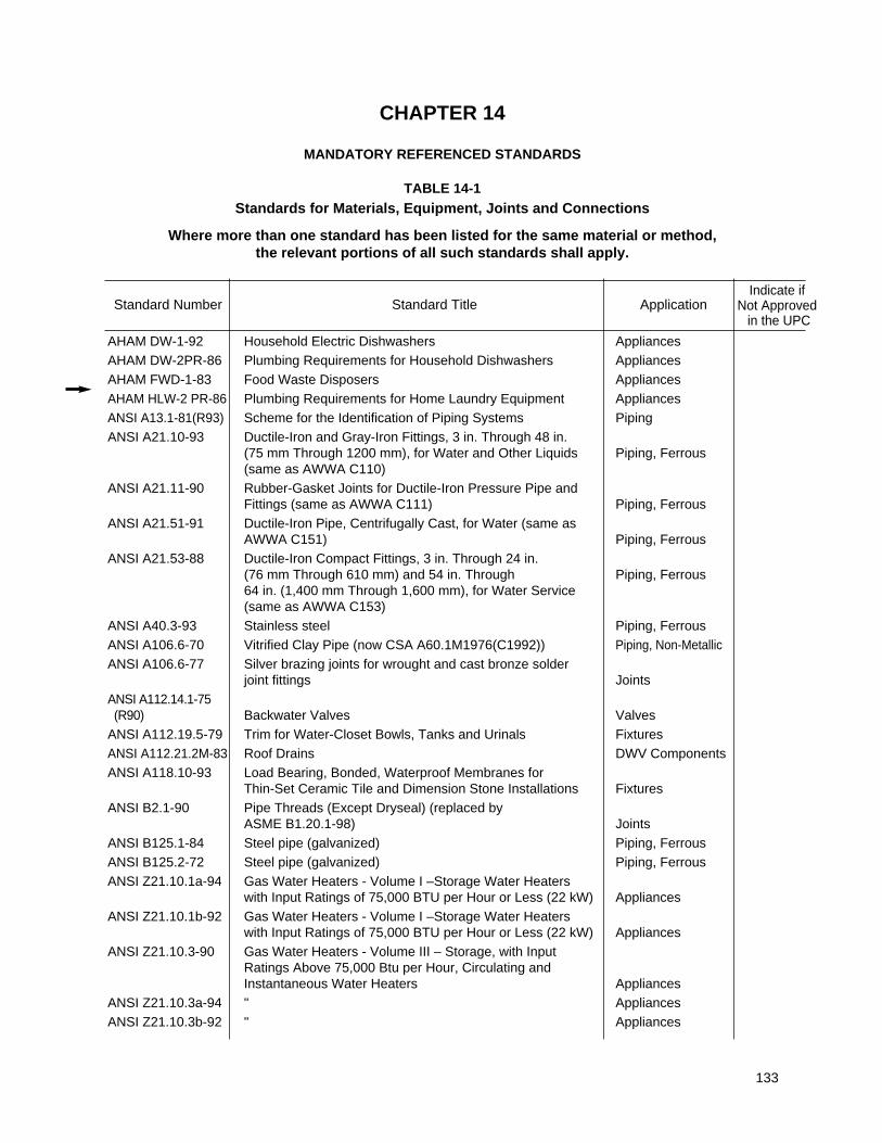
133
AHAM DW-1-92 Household Electric Dishwashers AppliancesAHAM DW-2PR-86 Plumbing Requirements for Household Dishwashers AppliancesAHAM FWD-1-83 Food Waste Disposers AppliancesAHAM HLW-2 PR-86 Plumbing Requirements for Home Laundry Equipment AppliancesANSI A13.1-81(R93) Scheme for the Identification of Piping Systems PipingANSI A21.10-93 Ductile-Iron and Gray-Iron Fittings, 3 in. Through 48 in.
(75 mm Through 1200 mm), for Water and Other Liquids Piping, Ferrous(same as AWWA C110)
ANSI A21.11-90 Rubber-Gasket Joints for Ductile-Iron Pressure Pipe and Fittings (same as AWWA C111) Piping, Ferrous
ANSI A21.51-91 Ductile-Iron Pipe, Centrifugally Cast, for Water (same as AWWA C151) Piping, Ferrous
ANSI A21.53-88 Ductile-Iron Compact Fittings, 3 in. Through 24 in. (76 mm Through 610 mm) and 54 in. Through Piping, Ferrous64 in. (1,400 mm Through 1,600 mm), for Water Service (same as AWWA C153)
ANSI A40.3-93 Stainless steel Piping, FerrousANSI A106.6-70 Vitrified Clay Pipe (now CSA A60.1M1976(C1992)) Piping, Non-MetallicANSI A106.6-77 Silver brazing joints for wrought and cast bronze solder
joint fittings JointsANSI A112.14.1-75 (R90) Backwater Valves Valves
ANSI A112.19.5-79 Trim for Water-Closet Bowls, Tanks and Urinals FixturesANSI A112.21.2M-83 Roof Drains DWV ComponentsANSI A118.10-93 Load Bearing, Bonded, Waterproof Membranes for
Thin-Set Ceramic Tile and Dimension Stone Installations FixturesANSI B2.1-90 Pipe Threads (Except Dryseal) (replaced by
ASME B1.20.1-98) JointsANSI B125.1-84 Steel pipe (galvanized) Piping, FerrousANSI B125.2-72 Steel pipe (galvanized) Piping, FerrousANSI Z21.10.1a-94 Gas Water Heaters - Volume I –Storage Water Heaters
with Input Ratings of 75,000 BTU per Hour or Less (22 kW) AppliancesANSI Z21.10.1b-92 Gas Water Heaters - Volume I –Storage Water Heaters
with Input Ratings of 75,000 BTU per Hour or Less (22 kW) AppliancesANSI Z21.10.3-90 Gas Water Heaters - Volume III – Storage, with Input
Ratings Above 75,000 Btu per Hour, Circulating and Instantaneous Water Heaters Appliances
ANSI Z21.10.3a-94 " AppliancesANSI Z21.10.3b-92 " Appliances
Standard Number Standard Title ApplicationIndicate if
Not Approvedin the UPC
CHAPTER 14
MANDATORY REFERENCED STANDARDS
TABLE 14-1Standards for Materials, Equipment, Joints and Connections
Where more than one standard has been listed for the same material or method, the relevant portions of all such standards shall apply.
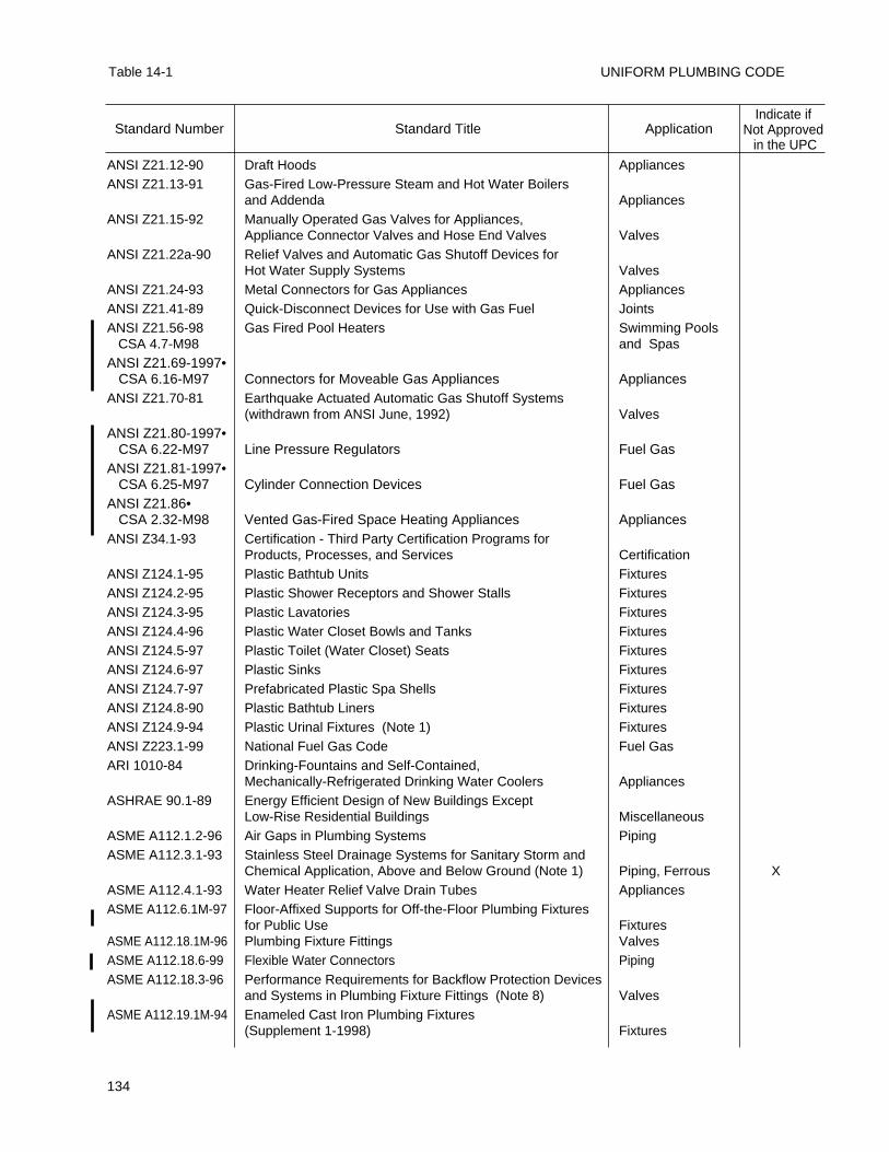
UNIFORM PLUMBING CODE
134
Table 14-1
ANSI Z21.12-90 Draft Hoods AppliancesANSI Z21.13-91 Gas-Fired Low-Pressure Steam and Hot Water Boilers
and Addenda AppliancesANSI Z21.15-92 Manually Operated Gas Valves for Appliances,
Appliance Connector Valves and Hose End Valves ValvesANSI Z21.22a-90 Relief Valves and Automatic Gas Shutoff Devices for
Hot Water Supply Systems ValvesANSI Z21.24-93 Metal Connectors for Gas Appliances AppliancesANSI Z21.41-89 Quick-Disconnect Devices for Use with Gas Fuel JointsANSI Z21.56-98 Gas Fired Pool Heaters Swimming Pools
CSA 4.7-M98 and SpasANSI Z21.69-1997•
CSA 6.16-M97 Connectors for Moveable Gas Appliances AppliancesANSI Z21.70-81 Earthquake Actuated Automatic Gas Shutoff Systems
(withdrawn from ANSI June, 1992) ValvesANSI Z21.80-1997•
CSA 6.22-M97 Line Pressure Regulators Fuel GasANSI Z21.81-1997•
CSA 6.25-M97 Cylinder Connection Devices Fuel GasANSI Z21.86•
CSA 2.32-M98 Vented Gas-Fired Space Heating Appliances AppliancesANSI Z34.1-93 Certification - Third Party Certification Programs for
Products, Processes, and Services CertificationANSI Z124.1-95 Plastic Bathtub Units FixturesANSI Z124.2-95 Plastic Shower Receptors and Shower Stalls FixturesANSI Z124.3-95 Plastic Lavatories FixturesANSI Z124.4-96 Plastic Water Closet Bowls and Tanks FixturesANSI Z124.5-97 Plastic Toilet (Water Closet) Seats FixturesANSI Z124.6-97 Plastic Sinks FixturesANSI Z124.7-97 Prefabricated Plastic Spa Shells FixturesANSI Z124.8-90 Plastic Bathtub Liners FixturesANSI Z124.9-94 Plastic Urinal Fixtures (Note 1) FixturesANSI Z223.1-99 National Fuel Gas Code Fuel GasARI 1010-84 Drinking-Fountains and Self-Contained,
Mechanically-Refrigerated Drinking Water Coolers AppliancesASHRAE 90.1-89 Energy Efficient Design of New Buildings Except
Low-Rise Residential Buildings MiscellaneousASME A112.1.2-96 Air Gaps in Plumbing Systems PipingASME A112.3.1-93 Stainless Steel Drainage Systems for Sanitary Storm and
Chemical Application, Above and Below Ground (Note 1) Piping, Ferrous XASME A112.4.1-93 Water Heater Relief Valve Drain Tubes AppliancesASME A112.6.1M-97 Floor-Affixed Supports for Off-the-Floor Plumbing Fixtures
for Public Use FixturesASME A112.18.1M-96 Plumbing Fixture Fittings ValvesASME A112.18.6-99 Flexible Water Connectors PipingASME A112.18.3-96 Performance Requirements for Backflow Protection Devices
and Systems in Plumbing Fixture Fittings (Note 8) ValvesASME A112.19.1M-94 Enameled Cast Iron Plumbing Fixtures
(Supplement 1-1998) Fixtures
Standard Number Standard Title ApplicationIndicate if
Not Approvedin the UPC
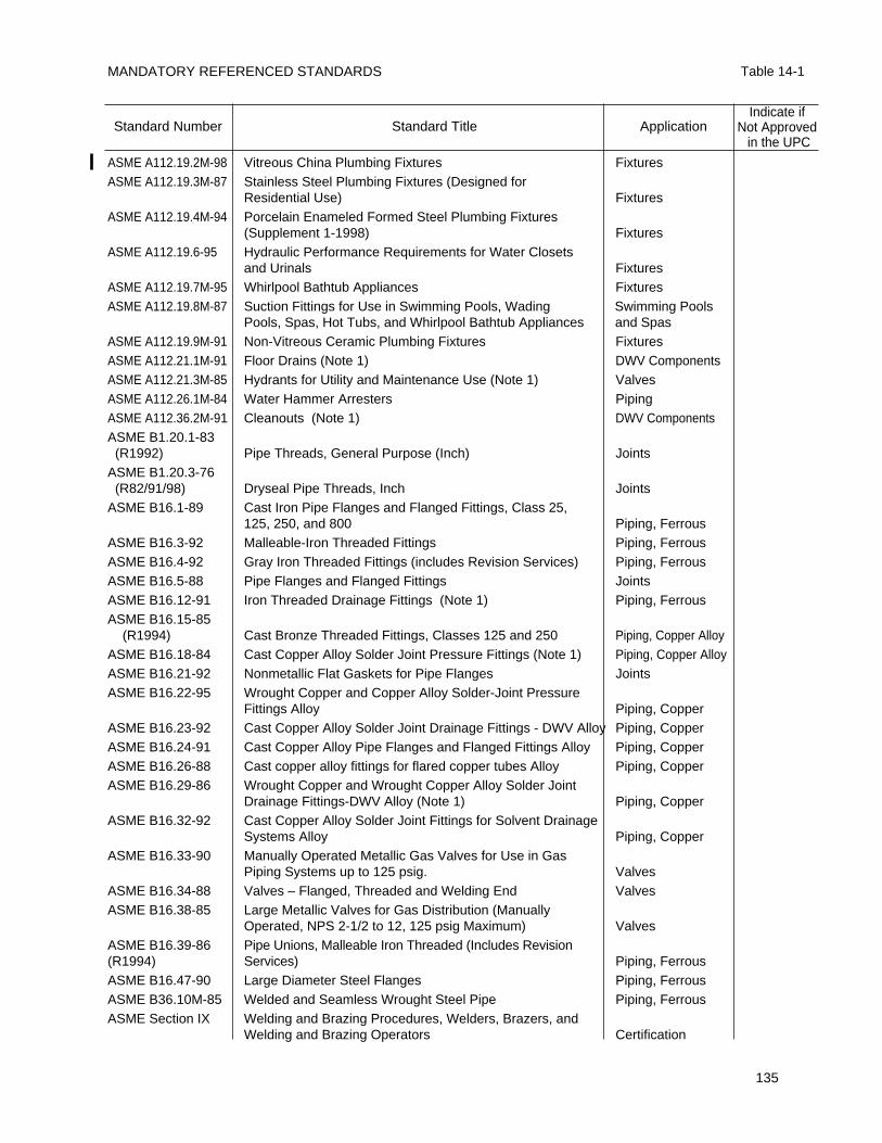
MANDATORY REFERENCED STANDARDS Table 14-1
135
ASME A112.19.2M-98 Vitreous China Plumbing Fixtures FixturesASME A112.19.3M-87 Stainless Steel Plumbing Fixtures (Designed for
Residential Use) FixturesASME A112.19.4M-94 Porcelain Enameled Formed Steel Plumbing Fixtures
(Supplement 1-1998) FixturesASME A112.19.6-95 Hydraulic Performance Requirements for Water Closets
and Urinals FixturesASME A112.19.7M-95 Whirlpool Bathtub Appliances FixturesASME A112.19.8M-87 Suction Fittings for Use in Swimming Pools, Wading Swimming Pools
Pools, Spas, Hot Tubs, and Whirlpool Bathtub Appliances and SpasASME A112.19.9M-91 Non-Vitreous Ceramic Plumbing Fixtures FixturesASME A112.21.1M-91 Floor Drains (Note 1) DWV ComponentsASME A112.21.3M-85 Hydrants for Utility and Maintenance Use (Note 1) ValvesASME A112.26.1M-84 Water Hammer Arresters PipingASME A112.36.2M-91 Cleanouts (Note 1) DWV ComponentsASME B1.20.1-83 (R1992) Pipe Threads, General Purpose (Inch) Joints
ASME B1.20.3-76 (R82/91/98) Dryseal Pipe Threads, Inch Joints
ASME B16.1-89 Cast Iron Pipe Flanges and Flanged Fittings, Class 25, 125, 250, and 800 Piping, Ferrous
ASME B16.3-92 Malleable-Iron Threaded Fittings Piping, FerrousASME B16.4-92 Gray Iron Threaded Fittings (includes Revision Services) Piping, FerrousASME B16.5-88 Pipe Flanges and Flanged Fittings JointsASME B16.12-91 Iron Threaded Drainage Fittings (Note 1) Piping, FerrousASME B16.15-85
(R1994) Cast Bronze Threaded Fittings, Classes 125 and 250 Piping, Copper AlloyASME B16.18-84 Cast Copper Alloy Solder Joint Pressure Fittings (Note 1) Piping, Copper Alloy ASME B16.21-92 Nonmetallic Flat Gaskets for Pipe Flanges JointsASME B16.22-95 Wrought Copper and Copper Alloy Solder-Joint Pressure
Fittings Alloy Piping, Copper ASME B16.23-92 Cast Copper Alloy Solder Joint Drainage Fittings - DWV Alloy Piping, Copper ASME B16.24-91 Cast Copper Alloy Pipe Flanges and Flanged Fittings Alloy Piping, Copper ASME B16.26-88 Cast copper alloy fittings for flared copper tubes Alloy Piping, Copper ASME B16.29-86 Wrought Copper and Wrought Copper Alloy Solder Joint
Drainage Fittings-DWV Alloy (Note 1) Piping, Copper ASME B16.32-92 Cast Copper Alloy Solder Joint Fittings for Solvent Drainage
Systems Alloy Piping, Copper ASME B16.33-90 Manually Operated Metallic Gas Valves for Use in Gas
Piping Systems up to 125 psig. ValvesASME B16.34-88 Valves – Flanged, Threaded and Welding End ValvesASME B16.38-85 Large Metallic Valves for Gas Distribution (Manually
Operated, NPS 2-1/2 to 12, 125 psig Maximum) ValvesASME B16.39-86 Pipe Unions, Malleable Iron Threaded (Includes Revision (R1994) Services) Piping, FerrousASME B16.47-90 Large Diameter Steel Flanges Piping, FerrousASME B36.10M-85 Welded and Seamless Wrought Steel Pipe Piping, FerrousASME Section IX Welding and Brazing Procedures, Welders, Brazers, and
Welding and Brazing Operators Certification
Standard Number Standard Title ApplicationIndicate if
Not Approvedin the UPC
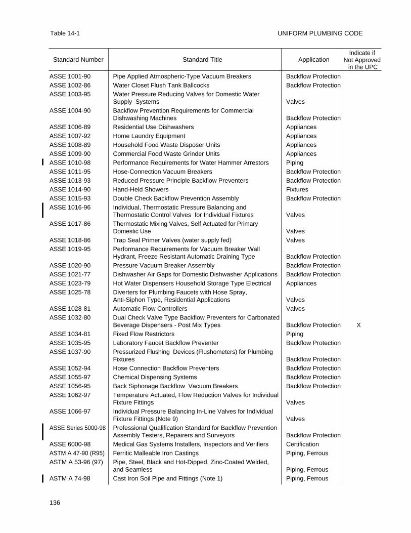
UNIFORM PLUMBING CODE
136
Table 14-1
ASSE 1001-90 Pipe Applied Atmospheric-Type Vacuum Breakers Backflow ProtectionASSE 1002-86 Water Closet Flush Tank Ballcocks Backflow ProtectionASSE 1003-95 Water Pressure Reducing Valves for Domestic Water
Supply Systems ValvesASSE 1004-90 Backflow Prevention Requirements for Commercial
Dishwashing Machines Backflow ProtectionASSE 1006-89 Residential Use Dishwashers AppliancesASSE 1007-92 Home Laundry Equipment AppliancesASSE 1008-89 Household Food Waste Disposer Units AppliancesASSE 1009-90 Commercial Food Waste Grinder Units AppliancesASSE 1010-98 Performance Requirements for Water Hammer Arrestors PipingASSE 1011-95 Hose-Connection Vacuum Breakers Backflow ProtectionASSE 1013-93 Reduced Pressure Principle Backflow Preventers Backflow ProtectionASSE 1014-90 Hand-Held Showers FixturesASSE 1015-93 Double Check Backflow Prevention Assembly Backflow ProtectionASSE 1016-96 Individual, Thermostatic Pressure Balancing and
Thermostatic Control Valves for Individual Fixtures ValvesASSE 1017-86 Thermostatic Mixing Valves, Self Actuated for Primary
Domestic Use ValvesASSE 1018-86 Trap Seal Primer Valves (water supply fed) ValvesASSE 1019-95 Performance Requirements for Vacuum Breaker Wall
Hydrant, Freeze Resistant Automatic Draining Type Backflow ProtectionASSE 1020-90 Pressure Vacuum Breaker Assembly Backflow ProtectionASSE 1021-77 Dishwasher Air Gaps for Domestic Dishwasher Applications Backflow ProtectionASSE 1023-79 Hot Water Dispensers Household Storage Type Electrical AppliancesASSE 1025-78 Diverters for Plumbing Faucets with Hose Spray,
Anti-Siphon Type, Residential Applications ValvesASSE 1028-81 Automatic Flow Controllers ValvesASSE 1032-80 Dual Check Valve Type Backflow Preventers for Carbonated
Beverage Dispensers - Post Mix Types Backflow Protection XASSE 1034-81 Fixed Flow Restrictors PipingASSE 1035-95 Laboratory Faucet Backflow Preventer Backflow ProtectionASSE 1037-90 Pressurized Flushing Devices (Flushometers) for Plumbing
Fixtures Backflow ProtectionASSE 1052-94 Hose Connection Backflow Preventers Backflow ProtectionASSE 1055-97 Chemical Dispensing Systems Backflow ProtectionASSE 1056-95 Back Siphonage Backflow Vacuum Breakers Backflow ProtectionASSE 1062-97 Temperature Actuated, Flow Reduction Valves for Individual
Fixture Fittings ValvesASSE 1066-97 Individual Pressure Balancing In-Line Valves for Individual
Fixture Fittings (Note 9) ValvesASSE Series 5000-98 Professional Qualification Standard for Backflow Prevention
Assembly Testers, Repairers and Surveyors Backflow ProtectionASSE 6000-98 Medical Gas Systems Installers, Inspectors and Verifiers CertificationASTM A 47-90 (R95) Ferritic Malleable Iron Castings Piping, FerrousASTM A 53-96 (97) Pipe, Steel, Black and Hot-Dipped, Zinc-Coated Welded,
and Seamless Piping, FerrousASTM A 74-98 Cast Iron Soil Pipe and Fittings (Note 1) Piping, Ferrous
Standard Number Standard Title ApplicationIndicate if
Not Approvedin the UPC
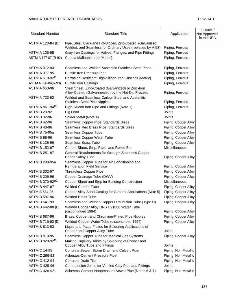
MANDATORY REFERENCED STANDARDS Table 14-1
137
ASTM A 120-84 [D] Pipe, Steel, Black and Hot-Dipped, Zinc-Coated, (Galvanized) Welded, and Seamless for Ordinary Uses (replaced by A 53) Piping, Ferrous
ASTM A 126-95 Gray Iron Castings for Valves, Flanges, and Pipe Fittings Piping, FerrousASTM A 197-87 (R-92) Cupola Malleable Iron [Metric] Piping, Ferrous
ASTM A 312-93 Seamless and Welded Austenitic Stainless Steel Pipes Piping, FerrousASTM A 377-95 Ductile-Iron Pressure Pipe Piping, FerrousASTM A 518-92e1 Corrosion-Resistant High-Silicon Iron Castings [Metric] Piping, FerrousASTM A 536-84(R-93) Ductile Iron Castings Piping, FerrousASTM A 653-96 Steel Sheet, Zinc-Coated (Galvanized) or Zinc-Iron
Alloy-Coated (Galvannealed) by the Hot-Dip Process Piping, FerrousASTM A 733-93 Welded and Seamless Carbon Steel and Austenitic
Stainless Steel Pipe Nipples Piping, FerrousASTM A 861-94e1 High-Silicon Iron Pipe and Fittings (Note 1) Piping, FerrousASTM B 29-92 Pig Lead JointsASTM B 32-96 Solder Metal (Note 4) JointsASTM B 42-96 Seamless Copper Pipe, Standards Sizes Piping, Copper AlloyASTM B 43-96 Seamless Red Brass Pipe, Standards Sizes Piping, Copper AlloyASTM B 75-95a Seamless Copper Tube Piping, Copper AlloyASTM B 88-96 Seamless Copper Water Tube Piping, Copper AlloyASTM B 135-96 Seamless Brass Tube Piping, Copper AlloyASTM B 152-97 Copper Sheet, Strip, Plate, and Rolled Bar MiscellaneousASTM B 251-97 General Requirements for Wrought Seamless Copper
Copper-Alloy Tube Piping, Copper AlloyASTM B 280-95a Seamless Copper Tube for Air Conditioning and
Refrigeration Field Service Piping, Copper AlloyASTM B 302-97 Threadless Copper Pipe Piping, Copper AlloyASTM B 306-96 Copper Drainage Tube (DWV) Piping, Copper AlloyASTM B 370-92e1 Copper Sheet and Strip for Building Construction MiscellaneousASTM B 447-97 Welded Copper Tube Piping, Copper AlloyASTM B 584-96 Copper Alloy Sand Casting for General Applications (Note 5) Piping, Copper AlloyASTM B 587-96 Welded Brass Tube Piping, Copper AlloyASTM B 641-93 Seamless and Welded Copper Distribution Tube (Type D) Piping, Copper AlloyASTM B 642-88 [D] Welded Copper Alloy UNS C21000 Water Tube
(discontinued 1994) Piping, Copper AlloyASTM B 687-96 Brass, Copper, and Chromium-Plated Pipe Nipples Piping, Copper AlloyASTM B 716-93 [D] Welded Copper Water Tube (discontinued 1994) Piping, Copper AlloyASTM B 813-93 Liquid and Paste Fluxes for Soldering Applications of
Copper and Copper Alloy Tube JointsASTM B 819-95 Seamless Copper Tube for Medical Gas Systems Piping, Copper AlloyASTM B 828-92e1 Making Capillary Joints by Soldering of Copper and
Copper Alloy Tube and Fittings JointsASTM C 14-95 Concrete Sewer, Storm Drain and Culvert Pipe Piping, Non-MetallicASTM C 296-93 Asbestos-Cement Pressure Pipe Piping, Non-MetallicASTM C 412-94 Concrete Drain Tile Piping, Non-MetallicASTM C 425-96 Compression Joints for Vitrified Clay Pipe and Fittings JointsASTM C 428-92 Asbestos-Cement Nonpressure Sewer Pipe (Notes 6 & 7) Piping, Non-Metallic
Standard Number Standard Title ApplicationIndicate if
Not Approvedin the UPC
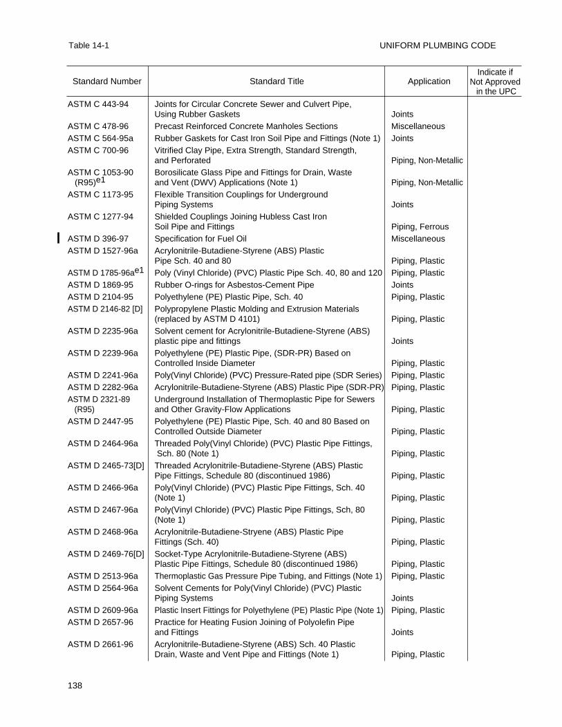
UNIFORM PLUMBING CODE
138
Table 14-1
ASTM C 443-94 Joints for Circular Concrete Sewer and Culvert Pipe, Using Rubber Gaskets Joints
ASTM C 478-96 Precast Reinforced Concrete Manholes Sections MiscellaneousASTM C 564-95a Rubber Gaskets for Cast Iron Soil Pipe and Fittings (Note 1) JointsASTM C 700-96 Vitrified Clay Pipe, Extra Strength, Standard Strength,
and Perforated Piping, Non-MetallicASTM C 1053-90 Borosilicate Glass Pipe and Fittings for Drain, Waste
(R95)e1 and Vent (DWV) Applications (Note 1) Piping, Non-MetallicASTM C 1173-95 Flexible Transition Couplings for Underground
Piping Systems JointsASTM C 1277-94 Shielded Couplings Joining Hubless Cast Iron
Soil Pipe and Fittings Piping, FerrousASTM D 396-97 Specification for Fuel Oil MiscellaneousASTM D 1527-96a Acrylonitrile-Butadiene-Styrene (ABS) Plastic
Pipe Sch. 40 and 80 Piping, PlasticASTM D 1785-96ae1 Poly (Vinyl Chloride) (PVC) Plastic Pipe Sch. 40, 80 and 120 Piping, PlasticASTM D 1869-95 Rubber O-rings for Asbestos-Cement Pipe JointsASTM D 2104-95 Polyethylene (PE) Plastic Pipe, Sch. 40 Piping, PlasticASTM D 2146-82 [D] Polypropylene Plastic Molding and Extrusion Materials
(replaced by ASTM D 4101) Piping, PlasticASTM D 2235-96a Solvent cement for Acrylonitrile-Butadiene-Styrene (ABS)
plastic pipe and fittings JointsASTM D 2239-96a Polyethylene (PE) Plastic Pipe, (SDR-PR) Based on
Controlled Inside Diameter Piping, PlasticASTM D 2241-96a Poly(Vinyl Chloride) (PVC) Pressure-Rated pipe (SDR Series) Piping, PlasticASTM D 2282-96a Acrylonitrile-Butadiene-Styrene (ABS) Plastic Pipe (SDR-PR) Piping, PlasticASTM D 2321-89 Underground Installation of Thermoplastic Pipe for Sewers
(R95) and Other Gravity-Flow Applications Piping, PlasticASTM D 2447-95 Polyethylene (PE) Plastic Pipe, Sch. 40 and 80 Based on
Controlled Outside Diameter Piping, PlasticASTM D 2464-96a Threaded Poly(Vinyl Chloride) (PVC) Plastic Pipe Fittings,
Sch. 80 (Note 1) Piping, PlasticASTM D 2465-73[D] Threaded Acrylonitrile-Butadiene-Styrene (ABS) Plastic
Pipe Fittings, Schedule 80 (discontinued 1986) Piping, PlasticASTM D 2466-96a Poly(Vinyl Chloride) (PVC) Plastic Pipe Fittings, Sch. 40
(Note 1) Piping, PlasticASTM D 2467-96a Poly(Vinyl Chloride) (PVC) Plastic Pipe Fittings, Sch, 80
(Note 1) Piping, PlasticASTM D 2468-96a Acrylonitrile-Butadiene-Stryene (ABS) Plastic Pipe
Fittings (Sch. 40) Piping, PlasticASTM D 2469-76[D] Socket-Type Acrylonitrile-Butadiene-Styrene (ABS)
Plastic Pipe Fittings, Schedule 80 (discontinued 1986) Piping, PlasticASTM D 2513-96a Thermoplastic Gas Pressure Pipe Tubing, and Fittings (Note 1) Piping, PlasticASTM D 2564-96a Solvent Cements for Poly(Vinyl Chloride) (PVC) Plastic
Piping Systems JointsASTM D 2609-96a Plastic Insert Fittings for Polyethylene (PE) Plastic Pipe (Note 1) Piping, PlasticASTM D 2657-96 Practice for Heating Fusion Joining of Polyolefin Pipe
and Fittings JointsASTM D 2661-96 Acrylonitrile-Butadiene-Styrene (ABS) Sch. 40 Plastic
Drain, Waste and Vent Pipe and Fittings (Note 1) Piping, Plastic
Standard Number Standard Title ApplicationIndicate if
Not Approvedin the UPC
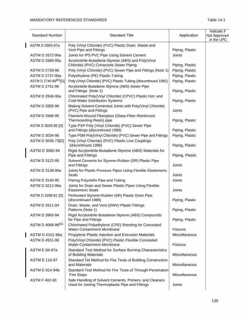
MANDATORY REFERENCED STANDARDS Table 14-1
139
ASTM D 2665-97a Poly (Vinyl Chloride) (PVC) Plastic Drain, Waste and Vent Pipe and Fittings Piping, Plastic
ASTM D 2672-96a Joints for IPS PVC Pipe Using Solvent Cement JointsASTM D 2680-95a Acrylonitrile-Butadiene-Styrene (ABS) and Poly(Vinyl
Chloride) (PVC) Composite Sewer Piping Piping, PlasticASTM D 2729-96 Poly (Vinyl Chloride) (PVC) Sewer Pipe and Fittings (Note 1) Piping, PlasticASTM D 2737-96a Polyethylene (PE) Plastic Tubing Piping, PlasticASTM D 2740-89e1[D] Poly (Vinyl Chloride) (PVC) Plastic Tubing (discontinued 1991) Piping, PlasticASTM D 2751-96 Acrylonitrile-Butadiene-Styrene (ABS) Sewer Pipe
and Fittings (Note 1) Piping, PlasticASTM D 2846-96a Chlorinated Poly(Vinyl Chloride) (CPVC) Plastic Hot- and
Cold-Water Distribution Systems Piping, PlasticASTM D 2855-96 Making Solvent-Cemented Joints with Poly(Vinyl Chloride)
(PVC) Pipe and Fittings JointsASTM D 2996-95 Filament-Wound Fiberglass (Glass-Fiber-Reinforced
Thermosetting Resin) pipe Piping, PlasticASTM D 3033-85 [D] Type PSP Poly (Vinyl Chloride) (PVC) Sewer Pipe
and Fittings (discontinued 1989) Piping, PlasticASTM D 3034-96 Type PSM Poly(Vinyl Chloride) (PVC) Sewer Pipe and Fittings Piping, PlasticASTM D 3036-73[D] Poly (Vinyl Chloride) (PVC) Plastic Line Couplings
(discontinued 1986) Piping, Plastic
ASTM D 3065-94 Rigid Acrylonitrile-Butadiene-Styrene (ABS) Materials forPipe and Fittings Piping, Plastic
ASTM D 3122-95 Solvent Cements for Styrene-Rubber (SR) Plastic Pipe and Fittings Joints
ASTM D 3139-96a Joints for Plastic Pressure Pipes Using Flexible Elastomeric Seals Joints
ASTM D 3140-90 Flaring Polyolefin Pipe and Tubing JointsASTM D 3212-96a Joints for Drain and Sewer Plastic Pipes Using Flexible
Elastomeric Seals JointsASTM D 3298-81 [D] Perforated Styrene-Rubber (SR) Plastic Drain Pipe
(discontinued 1989) Piping, PlasticASTM D 3311-94 Drain, Waste, and Vent (DWV) Plastic Fittings
Patterns (Note 1) Piping, PlasticASTM D 3965-94 Rigid Acrylonitrile-Butadiene-Styrene (ABS) Compounds
for Pipe and Fittings Piping, PlasticASTM D 4068-96e1 Chlorinated Polyethylene (CPE) Sheeting for Concealed
Water-Containment Membrane Fixtures
ASTM D 4101-96a Propylene Plastic Injection and Extrusion Materials MiscellaneousASTM D 4551-96 Poly(Vinyl Chloride) (PVC) Plastic Flexible Concealed
Water-Containment Membrane Fixtures
ASTM E 84-97a Standard Test Method for Surface Burning Characteristics of Building Materials Miscellaneous
ASTM E 119-97 Standard Tet Method for Fire Tests of Building Construction and Materials Miscellaneous
ASTM E 814-94b Standard Test Method for Fire Tests of Through-PenetrationFire Stops Miscellaneous
ASTM F 402-93 Safe Handling of Solvent Cements, Primers, and Cleaners Used for Joining Thermoplastic Pipe and Fittings Joints
Standard Number Standard Title ApplicationIndicate if
Not Approvedin the UPC
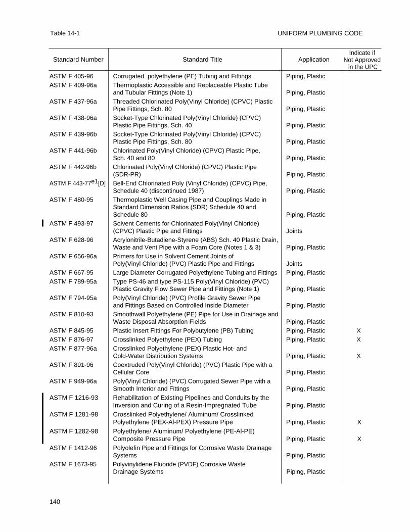
UNIFORM PLUMBING CODE
140
Table 14-1
ASTM F 405-96 Corrugated polyethylene (PE) Tubing and Fittings Piping, PlasticASTM F 409-96a Thermoplastic Accessible and Replaceable Plastic Tube
and Tubular Fittings (Note 1) Piping, PlasticASTM F 437-96a Threaded Chlorinated Poly(Vinyl Chloride) (CPVC) Plastic
Pipe Fittings, Sch. 80 Piping, PlasticASTM F 438-96a Socket-Type Chlorinated Poly(Vinyl Chloride) (CPVC)
Plastic Pipe Fittings, Sch. 40 Piping, PlasticASTM F 439-96b Socket-Type Chlorinated Poly(Vinyl Chloride) (CPVC)
Plastic Pipe Fittings, Sch. 80 Piping, PlasticASTM F 441-96b Chlorinated Poly(Vinyl Chloride) (CPVC) Plastic Pipe,
Sch. 40 and 80 Piping, PlasticASTM F 442-96b Chlorinated Poly(Vinyl Chloride) (CPVC) Plastic Pipe
(SDR-PR) Piping, PlasticASTM F 443-77e1[D] Bell-End Chlorinated Poly (Vinyl Chloride) (CPVC) Pipe,
Schedule 40 (discontinued 1987) Piping, PlasticASTM F 480-95 Thermoplastic Well Casing Pipe and Couplings Made in
Standard Dimension Ratios (SDR) Schedule 40 and Schedule 80 Piping, Plastic
ASTM F 493-97 Solvent Cements for Chlorinated Poly(Vinyl Chloride) (CPVC) Plastic Pipe and Fittings Joints
ASTM F 628-96 Acrylonitrile-Butadiene-Styrene (ABS) Sch. 40 Plastic Drain, Waste and Vent Pipe with a Foam Core (Notes 1 & 3) Piping, Plastic
ASTM F 656-96a Primers for Use in Solvent Cement Joints of Poly(Vinyl Chloride) (PVC) Plastic Pipe and Fittings Joints
ASTM F 667-95 Large Diameter Corrugated Polyethylene Tubing and Fittings Piping, PlasticASTM F 789-95a Type PS-46 and type PS-115 Poly(Vinyl Chloride) (PVC)
Plastic Gravity Flow Sewer Pipe and Fittings (Note 1) Piping, PlasticASTM F 794-95a Poly(Vinyl Chloride) (PVC) Profile Gravity Sewer Pipe
and Fittings Based on Controlled Inside Diameter Piping, PlasticASTM F 810-93 Smoothwall Polyethylene (PE) Pipe for Use in Drainage and
Waste Disposal Absorption Fields Piping, PlasticASTM F 845-95 Plastic Insert Fittings For Polybutylene (PB) Tubing Piping, Plastic XASTM F 876-97 Crosslinked Polyethylene (PEX) Tubing Piping, Plastic XASTM F 877-96a Crosslinked Polyethylene (PEX) Plastic Hot- and
Cold-Water Distribution Systems Piping, Plastic XASTM F 891-96 Coextruded Poly(Vinyl Chloride) (PVC) Plastic Pipe with a
Cellular Core Piping, PlasticASTM F 949-96a Poly(Vinyl Chloride) (PVC) Corrugated Sewer Pipe with a
Smooth Interior and Fittings Piping, Plastic
ASTM F 1216-93 Rehabilitation of Existing Pipelines and Conduits by the Inversion and Curing of a Resin-Impregnated Tube Piping, Plastic
ASTM F 1281-98 Crosslinked Polyethylene/ Aluminum/ Crosslinked Polyethylene (PEX-Al-PEX) Pressure Pipe Piping, Plastic X
ASTM F 1282-98 Polyethylene/ Aluminum/ Polyethylene (PE-Al-PE) Composite Pressure Pipe Piping, Plastic X
ASTM F 1412-96 Polyolefin Pipe and Fittings for Corrosive Waste Drainage Systems Piping, Plastic
ASTM F 1673-95 Polyvinylidene Fluoride (PVDF) Corrosive Waste Drainage Systems Piping, Plastic
Standard Number Standard Title ApplicationIndicate if
Not Approvedin the UPC
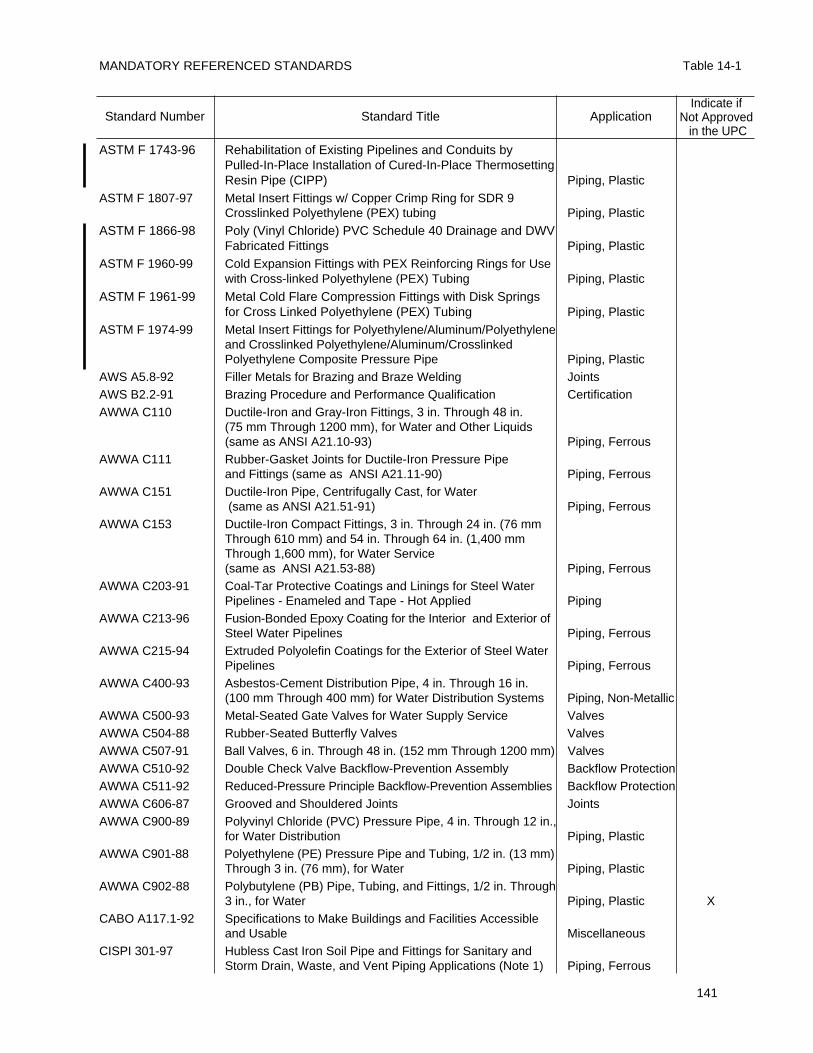
MANDATORY REFERENCED STANDARDS Table 14-1
141
ASTM F 1743-96 Rehabilitation of Existing Pipelines and Conduits by Pulled-In-Place Installation of Cured-In-Place ThermosettingResin Pipe (CIPP) Piping, Plastic
ASTM F 1807-97 Metal Insert Fittings w/ Copper Crimp Ring for SDR 9 Crosslinked Polyethylene (PEX) tubing Piping, Plastic
ASTM F 1866-98 Poly (Vinyl Chloride) PVC Schedule 40 Drainage and DWV Fabricated Fittings Piping, Plastic
ASTM F 1960-99 Cold Expansion Fittings with PEX Reinforcing Rings for Usewith Cross-linked Polyethylene (PEX) Tubing Piping, Plastic
ASTM F 1961-99 Metal Cold Flare Compression Fittings with Disk Springs for Cross Linked Polyethylene (PEX) Tubing Piping, Plastic
ASTM F 1974-99 Metal Insert Fittings for Polyethylene/Aluminum/Polyethyleneand Crosslinked Polyethylene/Aluminum/Crosslinked Polyethylene Composite Pressure Pipe Piping, Plastic
AWS A5.8-92 Filler Metals for Brazing and Braze Welding JointsAWS B2.2-91 Brazing Procedure and Performance Qualification CertificationAWWA C110 Ductile-Iron and Gray-Iron Fittings, 3 in. Through 48 in.
(75 mm Through 1200 mm), for Water and Other Liquids (same as ANSI A21.10-93) Piping, Ferrous
AWWA C111 Rubber-Gasket Joints for Ductile-Iron Pressure Pipe and Fittings (same as ANSI A21.11-90) Piping, Ferrous
AWWA C151 Ductile-Iron Pipe, Centrifugally Cast, for Water(same as ANSI A21.51-91) Piping, Ferrous
AWWA C153 Ductile-Iron Compact Fittings, 3 in. Through 24 in. (76 mm Through 610 mm) and 54 in. Through 64 in. (1,400 mm Through 1,600 mm), for Water Service(same as ANSI A21.53-88) Piping, Ferrous
AWWA C203-91 Coal-Tar Protective Coatings and Linings for Steel Water Pipelines - Enameled and Tape - Hot Applied Piping
AWWA C213-96 Fusion-Bonded Epoxy Coating for the Interior and Exterior of Steel Water Pipelines Piping, Ferrous
AWWA C215-94 Extruded Polyolefin Coatings for the Exterior of Steel Water Pipelines Piping, Ferrous
AWWA C400-93 Asbestos-Cement Distribution Pipe, 4 in. Through 16 in. (100 mm Through 400 mm) for Water Distribution Systems Piping, Non-Metallic
AWWA C500-93 Metal-Seated Gate Valves for Water Supply Service ValvesAWWA C504-88 Rubber-Seated Butterfly Valves ValvesAWWA C507-91 Ball Valves, 6 in. Through 48 in. (152 mm Through 1200 mm) ValvesAWWA C510-92 Double Check Valve Backflow-Prevention Assembly Backflow ProtectionAWWA C511-92 Reduced-Pressure Principle Backflow-Prevention Assemblies Backflow ProtectionAWWA C606-87 Grooved and Shouldered Joints JointsAWWA C900-89 Polyvinyl Chloride (PVC) Pressure Pipe, 4 in. Through 12 in.,
for Water Distribution Piping, PlasticAWWA C901-88 Polyethylene (PE) Pressure Pipe and Tubing, 1/2 in. (13 mm)
Through 3 in. (76 mm), for Water Piping, PlasticAWWA C902-88 Polybutylene (PB) Pipe, Tubing, and Fittings, 1/2 in. Through
3 in., for Water Piping, Plastic XCABO A117.1-92 Specifications to Make Buildings and Facilities Accessible
and Usable MiscellaneousCISPI 301-97 Hubless Cast Iron Soil Pipe and Fittings for Sanitary and
Storm Drain, Waste, and Vent Piping Applications (Note 1) Piping, Ferrous
Standard Number Standard Title ApplicationIndicate if
Not Approvedin the UPC
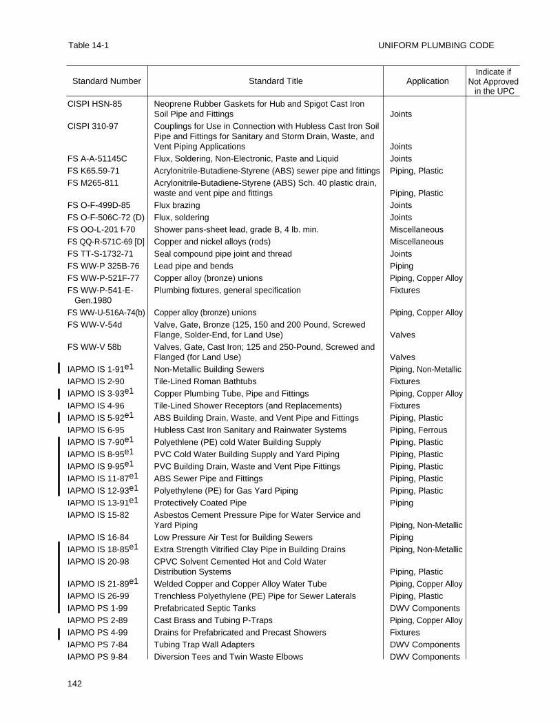
UNIFORM PLUMBING CODE
142
Table 14-1
CISPI HSN-85 Neoprene Rubber Gaskets for Hub and Spigot Cast Iron Soil Pipe and Fittings Joints
CISPI 310-97 Couplings for Use in Connection with Hubless Cast Iron Soil Pipe and Fittings for Sanitary and Storm Drain, Waste, and Vent Piping Applications Joints
FS A-A-51145C Flux, Soldering, Non-Electronic, Paste and Liquid JointsFS K65.59-71 Acrylonitrile-Butadiene-Styrene (ABS) sewer pipe and fittings Piping, PlasticFS M265-811 Acrylonitrile-Butadiene-Styrene (ABS) Sch. 40 plastic drain,
waste and vent pipe and fittings Piping, PlasticFS O-F-499D-85 Flux brazing JointsFS O-F-506C-72 (D) Flux, soldering JointsFS OO-L-201 f-70 Shower pans-sheet lead, grade B, 4 lb. min. MiscellaneousFS QQ-R-571C-69 [D] Copper and nickel alloys (rods) MiscellaneousFS TT-S-1732-71 Seal compound pipe joint and thread JointsFS WW-P 325B-76 Lead pipe and bends PipingFS WW-P-521F-77 Copper alloy (bronze) unions Piping, Copper AlloyFS WW-P-541-E- Plumbing fixtures, general specification Fixtures
Gen.1980FS WW-U-516A-74(b) Copper alloy (bronze) unions Piping, Copper AlloyFS WW-V-54d Valve, Gate, Bronze (125, 150 and 200 Pound, Screwed
Flange, Solder-End, for Land Use) ValvesFS WW-V 58b Valves, Gate, Cast Iron; 125 and 250-Pound, Screwed and
Flanged (for Land Use) ValvesIAPMO IS 1-91e1 Non-Metallic Building Sewers Piping, Non-MetallicIAPMO IS 2-90 Tile-Lined Roman Bathtubs FixturesIAPMO IS 3-93e1 Copper Plumbing Tube, Pipe and Fittings Piping, Copper AlloyIAPMO IS 4-96 Tile-Lined Shower Receptors (and Replacements) FixturesIAPMO IS 5-92e1 ABS Building Drain, Waste, and Vent Pipe and Fittings Piping, PlasticIAPMO IS 6-95 Hubless Cast Iron Sanitary and Rainwater Systems Piping, FerrousIAPMO IS 7-90e1 Polyethlene (PE) cold Water Building Supply Piping, PlasticIAPMO IS 8-95e1 PVC Cold Water Building Supply and Yard Piping Piping, PlasticIAPMO IS 9-95e1 PVC Building Drain, Waste and Vent Pipe Fittings Piping, PlasticIAPMO IS 11-87e1 ABS Sewer Pipe and Fittings Piping, PlasticIAPMO IS 12-93e1 Polyethylene (PE) for Gas Yard Piping Piping, PlasticIAPMO IS 13-91e1 Protectively Coated Pipe PipingIAPMO IS 15-82 Asbestos Cement Pressure Pipe for Water Service and
Yard Piping Piping, Non-MetallicIAPMO IS 16-84 Low Pressure Air Test for Building Sewers PipingIAPMO IS 18-85e1 Extra Strength Vitrified Clay Pipe in Building Drains Piping, Non-MetallicIAPMO IS 20-98 CPVC Solvent Cemented Hot and Cold Water
Distribution Systems Piping, PlasticIAPMO IS 21-89e1 Welded Copper and Copper Alloy Water Tube Piping, Copper AlloyIAPMO IS 26-99 Trenchless Polyethylene (PE) Pipe for Sewer Laterals Piping, PlasticIAPMO PS 1-99 Prefabricated Septic Tanks DWV ComponentsIAPMO PS 2-89 Cast Brass and Tubing P-Traps Piping, Copper AlloyIAPMO PS 4-99 Drains for Prefabricated and Precast Showers FixturesIAPMO PS 7-84 Tubing Trap Wall Adapters DWV ComponentsIAPMO PS 9-84 Diversion Tees and Twin Waste Elbows DWV Components
Standard Number Standard Title ApplicationIndicate if
Not Approvedin the UPC
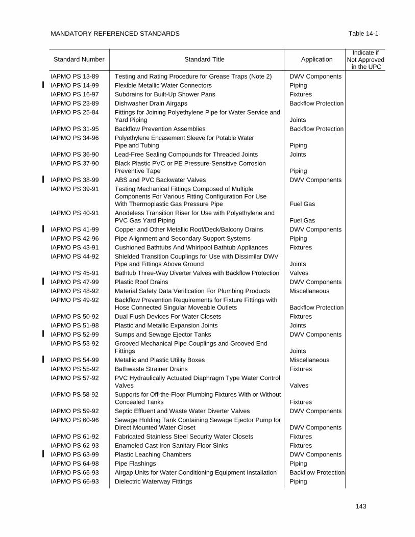
MANDATORY REFERENCED STANDARDS Table 14-1
143
IAPMO PS 13-89 Testing and Rating Procedure for Grease Traps (Note 2) DWV ComponentsIAPMO PS 14-99 Flexible Metallic Water Connectors PipingIAPMO PS 16-97 Subdrains for Built-Up Shower Pans FixturesIAPMO PS 23-89 Dishwasher Drain Airgaps Backflow ProtectionIAPMO PS 25-84 Fittings for Joining Polyethylene Pipe for Water Service and
Yard Piping JointsIAPMO PS 31-95 Backflow Prevention Assemblies Backflow ProtectionIAPMO PS 34-96 Polyethylene Encasement Sleeve for Potable Water
Pipe and Tubing PipingIAPMO PS 36-90 Lead-Free Sealing Compounds for Threaded Joints JointsIAPMO PS 37-90 Black Plastic PVC or PE Pressure-Sensitive Corrosion
Preventive Tape PipingIAPMO PS 38-99 ABS and PVC Backwater Valves DWV ComponentsIAPMO PS 39-91 Testing Mechanical Fittings Composed of Multiple
Components For Various Fitting Configuration For Use With Thermoplastic Gas Pressure Pipe Fuel Gas
IAPMO PS 40-91 Anodeless Transition Riser for Use with Polyethylene and PVC Gas Yard Piping Fuel Gas
IAPMO PS 41-99 Copper and Other Metallic Roof/Deck/Balcony Drains DWV ComponentsIAPMO PS 42-96 Pipe Alignment and Secondary Support Systems PipingIAPMO PS 43-91 Cushioned Bathtubs And Whirlpool Bathtub Appliances FixturesIAPMO PS 44-92 Shielded Transition Couplings for Use with Dissimilar DWV
Pipe and Fittings Above Ground JointsIAPMO PS 45-91 Bathtub Three-Way Diverter Valves with Backflow Protection ValvesIAPMO PS 47-99 Plastic Roof Drains DWV ComponentsIAPMO PS 48-92 Material Safety Data Verification For Plumbing Products MiscellaneousIAPMO PS 49-92 Backflow Prevention Requirements for Fixture Fittings with
Hose Connected Singular Moveable Outlets Backflow ProtectionIAPMO PS 50-92 Dual Flush Devices For Water Closets FixturesIAPMO PS 51-98 Plastic and Metallic Expansion Joints JointsIAPMO PS 52-99 Sumps and Sewage Ejector Tanks DWV ComponentsIAPMO PS 53-92 Grooved Mechanical Pipe Couplings and Grooved End
Fittings JointsIAPMO PS 54-99 Metallic and Plastic Utility Boxes MiscellaneousIAPMO PS 55-92 Bathwaste Strainer Drains FixturesIAPMO PS 57-92 PVC Hydraulically Actuated Diaphragm Type Water Control
Valves ValvesIAPMO PS 58-92 Supports for Off-the-Floor Plumbing Fixtures With or Without
Concealed Tanks FixturesIAPMO PS 59-92 Septic Effluent and Waste Water Diverter Valves DWV ComponentsIAPMO PS 60-96 Sewage Holding Tank Containing Sewage Ejector Pump for
Direct Mounted Water Closet DWV ComponentsIAPMO PS 61-92 Fabricated Stainless Steel Security Water Closets FixturesIAPMO PS 62-93 Enameled Cast Iron Sanitary Floor Sinks FixturesIAPMO PS 63-99 Plastic Leaching Chambers DWV ComponentsIAPMO PS 64-98 Pipe Flashings PipingIAPMO PS 65-93 Airgap Units for Water Conditioning Equipment Installation Backflow ProtectionIAPMO PS 66-93 Dielectric Waterway Fittings Piping
Standard Number Standard Title ApplicationIndicate if
Not Approvedin the UPC
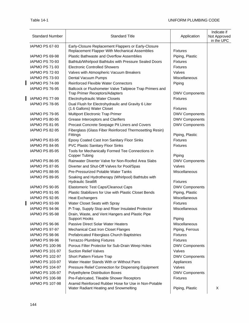
UNIFORM PLUMBING CODE
144
Table 14-1
IAPMO PS 67-93 Early-Closure Replacement Flappers or Early-Closure Replacement Flapper With Mechanical Assemblies Fixtures
IAPMO PS 69-98 Plastic Bathwaste and Overflow Assemblies Piping, PlasticIAPMO PS 70-93 Bathtub/Whirlpool Bathtubs with Pressure Sealed Doors FixturesIAPMO PS 71-93 Electronic Controlled Showers FixturesIAPMO PS 72-93 Valves with Atmospheric Vacuum Breakers ValvesIAPMO PS 73-93 Dental Vacuum Pumps MiscellaneousIAPMO PS 74-99 Reinforced Flexible Water Connectors PipingIAPMO PS 76-95 Ballcock or Flushometer Valve Tailpiece Trap Primers and
Trap Primer Receptors/Adapters DWV ComponentsIAPMO PS 77-99 Electrohydraulic Water Closets FixturesIAPMO PS 78-95 Dual Flush for Electrohydraulic and Gravity 6 Liter
(1.6 Gallons) Water Closet FixturesIAPMO PS 79-95 Multiport Electronic Trap Primer DWV ComponentsIAPMO PS 80-95 Grease Interceptors and Clarifiers DWV ComponentsIAPMO PS 81-95 Precast Concrete Seepage Pit Liners and Covers DWV ComponentsIAPMO PS 82-95 Fiberglass (Glass Fiber Reinforced Thermosetting Resin)
Fittings Piping, PlasticIAPMO PS 83-95 Epoxy Coated Cast Iron Sanitary Floor Sinks FixturesIAPMO PS 84-95 PVC Plastic Sanitary Floor Sinks FixturesIAPMO PS 85-95 Tools for Mechanically Formed Tee Connections in
Copper Tubing PipingIAPMO PS 86-95 Rainwater Diverter Valve for Non-Roofed Area Slabs DWV ComponentsIAPMO PS 87-95 Diverter and Shut-Off Valves for Pool/Spas ValvesIAPMO PS 88-95 Pre-Pressurized Potable Water Tanks MiscellaneousIAPMO PS 89-95 Soaking and Hydrotherapy (Whirlpool) Bathtubs with
Hydraulic Seatlift FixturesIAPMO PS 90-95 Elastomeric Test Caps/Cleanout Caps DWV ComponentsIAPMO PS 91-95 Plastic Stabilizers for Use with Plastic Closet Bends Piping, PlasticIAPMO PS 92-95 Heat Exchangers MiscellaneousIAPMO PS 93-99 Water Closet Seats with Spray FixturesIAPMO PS 94-96 P-Trap, Supply Stop and Riser Insulated Protector MiscellaneousIAPMO PS 95-98 Drain, Waste, and Vent Hangers and Plastic Pipe
Support Hooks PipingIAPMO PS 96-96 Passive Direct Solar Water Heaters MiscellaneousIAPMO PS 97-97 Mechanical Cast Iron Closet Flanges Piping, FerrousIAPMO PS 98-96 Prefabricated Fiberglass Church Baptistries FixturesIAPMO PS 99-96 Terrazzo Plumbing Fixtures FixturesIAPMO PS 100-96 Porous Filter Protector for Sub-Drain Weep Holes DWV ComponentsIAPMO PS 101-97 Suction Relief Valves ValvesIAPMO PS 102-97 Short Pattern Fixture Trap DWV ComponentsIAPMO PS 103-97 Water Heater Stands With or Without Pans AppliancesIAPMO PS 104-97 Pressure Relief Connection for Dispensing Equipment ValvesIAPMO PS 105-97 Polyethylene Distribution Boxes DWV ComponentsIAPMO PS 106-98 Pre-Fabricated, Tileable Shower Receptors FixturesIAPMO PS 107-98 Aramid Reinforced Rubber Hose for Use in Non-Potable
Water Radiant Heating and Snowmelting Piping, Plastic X
Standard Number Standard Title ApplicationIndicate if
Not Approvedin the UPC
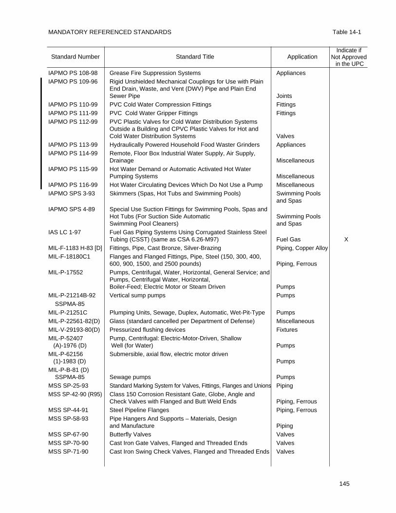
MANDATORY REFERENCED STANDARDS Table 14-1
145
IAPMO PS 108-98 Grease Fire Suppression Systems AppliancesIAPMO PS 109-96 Rigid Unshielded Mechanical Couplings for Use with Plain
End Drain, Waste, and Vent (DWV) Pipe and Plain EndSewer Pipe Joints
IAPMO PS 110-99 PVC Cold Water Compression Fittings FittingsIAPMO PS 111-99 PVC Cold Water Gripper Fittings FittingsIAPMO PS 112-99 PVC Plastic Valves for Cold Water Distribution Systems
Outside a Building and CPVC Plastic Valves for Hot andCold Water Distribution Systems Valves
IAPMO PS 113-99 Hydraulically Powered Household Food Waster Grinders AppliancesIAPMO PS 114-99 Remote, Floor Box Industrial Water Supply, Air Supply,
Drainage MiscellaneousIAPMO PS 115-99 Hot Water Demand or Automatic Activated Hot Water
Pumping Systems MiscellaneousIAPMO PS 116-99 Hot Water Circulating Devices Which Do Not Use a Pump MiscellaneousIAPMO SPS 3-93 Skimmers (Spas, Hot Tubs and Swimming Pools) Swimming Pools
and SpasIAPMO SPS 4-89 Special Use Suction Fittings for Swimming Pools, Spas and
Hot Tubs (For Suction Side Automatic Swimming Pools Swimming Pool Cleaners) and Spas
IAS LC 1-97 Fuel Gas Piping Systems Using Corrugated Stainless Steel Tubing (CSST) (same as CSA 6.26-M97) Fuel Gas X
MIL-F-1183 H-83 [D] Fittings, Pipe, Cast Bronze, Silver-Brazing Piping, Copper AlloyMIL-F-18180C1 Flanges and Flanged Fittings, Pipe, Steel (150, 300, 400,
600, 900, 1500, and 2500 pounds) Piping, FerrousMIL-P-17552 Pumps, Centrifugal, Water, Horizontal, General Service; and
Pumps, Centrifugal Water, Horizontal,Boiler-Feed; Electric Motor or Steam Driven Pumps
MIL-P-21214B-92 Vertical sump pumps PumpsSSPMA-85
MIL-P-21251C Plumping Units, Sewage, Duplex, Automatic, Wet-Pit-Type PumpsMIL-P-22561-82(D) Glass (standard cancelled per Department of Defense) MiscellaneousMIL-V-29193-80(D) Pressurized flushing devices FixturesMIL-P-52407 Pump, Centrifugal: Electric-Motor-Driven, Shallow
(A)-1976 (D) Well (for Water) PumpsMIL-P-62156 Submersible, axial flow, electric motor driven
(1)-1983 (D) PumpsMIL-P-B-81 (D)
SSPMA-85 Sewage pumps PumpsMSS SP-25-93 Standard Marking System for Valves, Fittings, Flanges and Unions PipingMSS SP-42-90 (R95) Class 150 Corrosion Resistant Gate, Globe, Angle and
Check Valves with Flanged and Butt Weld Ends Piping, FerrousMSS SP-44-91 Steel Pipeline Flanges Piping, FerrousMSS SP-58-93 Pipe Hangers And Supports – Materials, Design
and Manufacture PipingMSS SP-67-90 Butterfly Valves ValvesMSS SP-70-90 Cast Iron Gate Valves, Flanged and Threaded Ends ValvesMSS SP-71-90 Cast Iron Swing Check Valves, Flanged and Threaded Ends Valves
Standard Number Standard Title ApplicationIndicate if
Not Approvedin the UPC
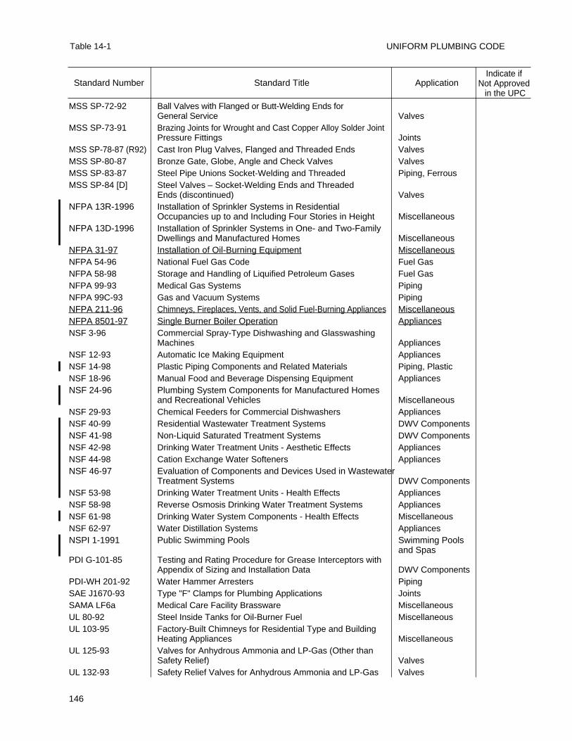
UNIFORM PLUMBING CODE
146
Table 14-1
MSS SP-72-92 Ball Valves with Flanged or Butt-Welding Ends for General Service Valves
MSS SP-73-91 Brazing Joints for Wrought and Cast Copper Alloy Solder Joint Pressure Fittings Joints
MSS SP-78-87 (R92) Cast Iron Plug Valves, Flanged and Threaded Ends ValvesMSS SP-80-87 Bronze Gate, Globe, Angle and Check Valves ValvesMSS SP-83-87 Steel Pipe Unions Socket-Welding and Threaded Piping, FerrousMSS SP-84 [D] Steel Valves – Socket-Welding Ends and Threaded
Ends (discontinued) ValvesNFPA 13R-1996 Installation of Sprinkler Systems in Residential
Occupancies up to and Including Four Stories in Height MiscellaneousNFPA 13D-1996 Installation of Sprinkler Systems in One- and Two-Family
Dwellings and Manufactured Homes MiscellaneousNFPA 31-97 Installation of Oil-Burning Equipment MiscellaneousNFPA 54-96 National Fuel Gas Code Fuel GasNFPA 58-98 Storage and Handling of Liquified Petroleum Gases Fuel GasNFPA 99-93 Medical Gas Systems PipingNFPA 99C-93 Gas and Vacuum Systems PipingNFPA 211-96 Chimneys, Fireplaces, Vents, and Solid Fuel-Burning Appliances MiscellaneousNFPA 8501-97 Single Burner Boiler Operation AppliancesNSF 3-96 Commercial Spray-Type Dishwashing and Glasswashing
Machines AppliancesNSF 12-93 Automatic Ice Making Equipment AppliancesNSF 14-98 Plastic Piping Components and Related Materials Piping, PlasticNSF 18-96 Manual Food and Beverage Dispensing Equipment AppliancesNSF 24-96 Plumbing System Components for Manufactured Homes
and Recreational Vehicles MiscellaneousNSF 29-93 Chemical Feeders for Commercial Dishwashers AppliancesNSF 40-99 Residential Wastewater Treatment Systems DWV ComponentsNSF 41-98 Non-Liquid Saturated Treatment Systems DWV ComponentsNSF 42-98 Drinking Water Treatment Units - Aesthetic Effects AppliancesNSF 44-98 Cation Exchange Water Softeners AppliancesNSF 46-97 Evaluation of Components and Devices Used in Wastewater
Treatment Systems DWV ComponentsNSF 53-98 Drinking Water Treatment Units - Health Effects AppliancesNSF 58-98 Reverse Osmosis Drinking Water Treatment Systems AppliancesNSF 61-98 Drinking Water System Components - Health Effects MiscellaneousNSF 62-97 Water Distillation Systems AppliancesNSPI 1-1991 Public Swimming Pools Swimming Pools
and SpasPDI G-101-85 Testing and Rating Procedure for Grease Interceptors with
Appendix of Sizing and Installation Data DWV ComponentsPDI-WH 201-92 Water Hammer Arresters PipingSAE J1670-93 Type "F" Clamps for Plumbing Applications JointsSAMA LF6a Medical Care Facility Brassware MiscellaneousUL 80-92 Steel Inside Tanks for Oil-Burner Fuel MiscellaneousUL 103-95 Factory-Built Chimneys for Residential Type and Building
Heating Appliances MiscellaneousUL 125-93 Valves for Anhydrous Ammonia and LP-Gas (Other than
Safety Relief) ValvesUL 132-93 Safety Relief Valves for Anhydrous Ammonia and LP-Gas Valves
Standard Number Standard Title ApplicationIndicate if
Not Approvedin the UPC
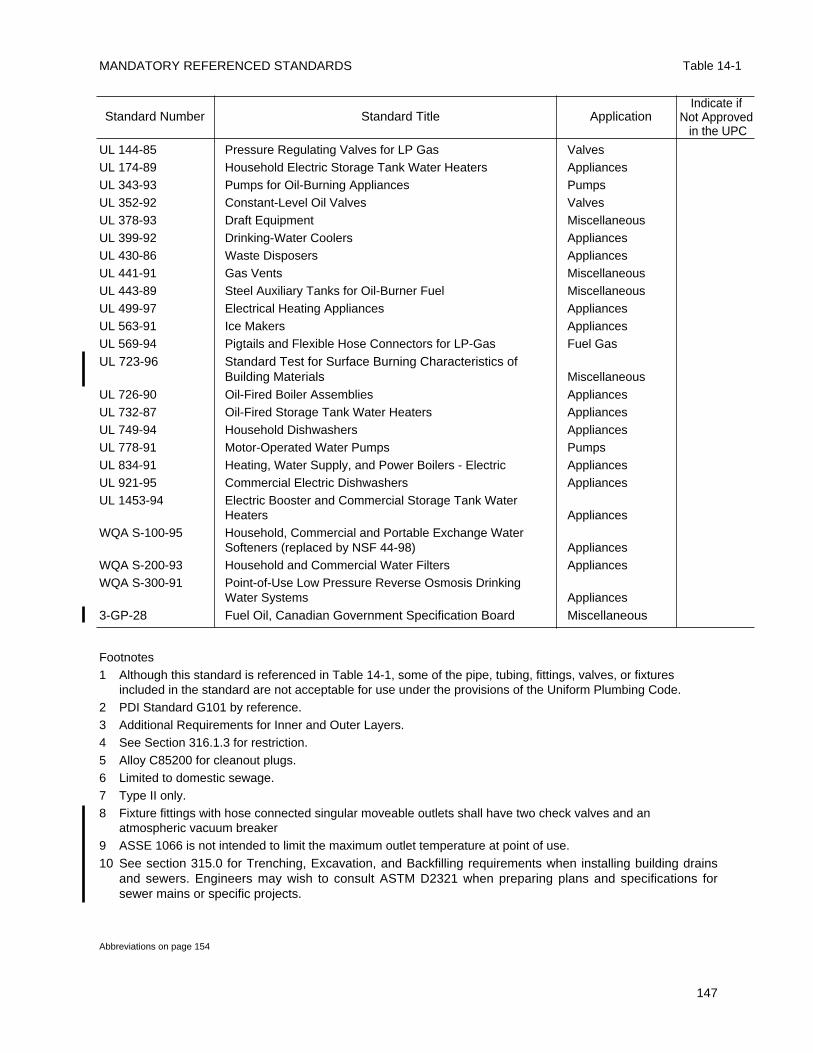
MANDATORY REFERENCED STANDARDS Table 14-1
147
UL 144-85 Pressure Regulating Valves for LP Gas ValvesUL 174-89 Household Electric Storage Tank Water Heaters AppliancesUL 343-93 Pumps for Oil-Burning Appliances PumpsUL 352-92 Constant-Level Oil Valves ValvesUL 378-93 Draft Equipment MiscellaneousUL 399-92 Drinking-Water Coolers AppliancesUL 430-86 Waste Disposers AppliancesUL 441-91 Gas Vents MiscellaneousUL 443-89 Steel Auxiliary Tanks for Oil-Burner Fuel MiscellaneousUL 499-97 Electrical Heating Appliances AppliancesUL 563-91 Ice Makers AppliancesUL 569-94 Pigtails and Flexible Hose Connectors for LP-Gas Fuel Gas
UL 723-96 Standard Test for Surface Burning Characteristics of Building Materials Miscellaneous
UL 726-90 Oil-Fired Boiler Assemblies AppliancesUL 732-87 Oil-Fired Storage Tank Water Heaters AppliancesUL 749-94 Household Dishwashers AppliancesUL 778-91 Motor-Operated Water Pumps PumpsUL 834-91 Heating, Water Supply, and Power Boilers - Electric AppliancesUL 921-95 Commercial Electric Dishwashers AppliancesUL 1453-94 Electric Booster and Commercial Storage Tank Water
Heaters AppliancesWQA S-100-95 Household, Commercial and Portable Exchange Water
Softeners (replaced by NSF 44-98) AppliancesWQA S-200-93 Household and Commercial Water Filters AppliancesWQA S-300-91 Point-of-Use Low Pressure Reverse Osmosis Drinking
Water Systems Appliances
3-GP-28 Fuel Oil, Canadian Government Specification Board Miscellaneous
Footnotes1 Although this standard is referenced in Table 14-1, some of the pipe, tubing, fittings, valves, or fixtures
included in the standard are not acceptable for use under the provisions of the Uniform Plumbing Code.2 PDI Standard G101 by reference.3 Additional Requirements for Inner and Outer Layers.4 See Section 316.1.3 for restriction.5 Alloy C85200 for cleanout plugs.6 Limited to domestic sewage.7 Type II only.8 Fixture fittings with hose connected singular moveable outlets shall have two check valves and an
atmospheric vacuum breaker9 ASSE 1066 is not intended to limit the maximum outlet temperature at point of use.
10 See section 315.0 for Trenching, Excavation, and Backfilling requirements when installing building drainsand sewers. Engineers may wish to consult ASTM D2321 when preparing plans and specifications forsewer mains or specific projects.
Abbreviations on page 154
Standard Number Standard Title ApplicationIndicate if
Not Approvedin the UPC
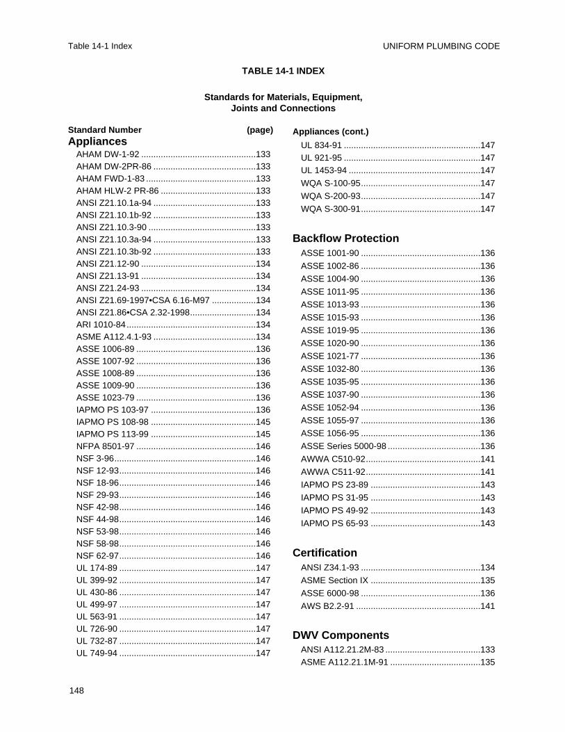
UNIFORM PLUMBING CODE
148
Table 14-1 Index
Appliances (cont.)
UL 834-91 ........................................................147UL 921-95 ........................................................147UL 1453-94 ......................................................147
WQA S-100-95.................................................147
WQA S-200-93.................................................147
WQA S-300-91.................................................147
Backflow ProtectionASSE 1001-90 .................................................136
ASSE 1002-86 .................................................136
ASSE 1004-90 .................................................136
ASSE 1011-95 .................................................136
ASSE 1013-93 .................................................136
ASSE 1015-93 .................................................136
ASSE 1019-95 .................................................136
ASSE 1020-90 .................................................136
ASSE 1021-77 .................................................136
ASSE 1032-80 .................................................136
ASSE 1035-95 .................................................136
ASSE 1037-90 .................................................136
ASSE 1052-94 .................................................136
ASSE 1055-97 .................................................136
ASSE 1056-95 .................................................136
ASSE Series 5000-98 ......................................136
AWWA C510-92...............................................141
AWWA C511-92...............................................141
IAPMO PS 23-89 .............................................143
IAPMO PS 31-95 .............................................143
IAPMO PS 49-92 .............................................143
IAPMO PS 65-93 .............................................143
CertificationANSI Z34.1-93 .................................................134
ASME Section IX .............................................135
ASSE 6000-98 .................................................136
AWS B2.2-91 ...................................................141
DWV ComponentsANSI A112.21.2M-83 .......................................133ASME A112.21.1M-91 .....................................135
Standard Number (page)Appliances
AHAM DW-1-92 ...............................................133AHAM DW-2PR-86 ..........................................133AHAM FWD-1-83 .............................................133AHAM HLW-2 PR-86 .......................................133ANSI Z21.10.1a-94 ..........................................133ANSI Z21.10.1b-92 ..........................................133ANSI Z21.10.3-90 ............................................133ANSI Z21.10.3a-94 ..........................................133ANSI Z21.10.3b-92 ..........................................133ANSI Z21.12-90 ...............................................134ANSI Z21.13-91 ...............................................134ANSI Z21.24-93 ...............................................134ANSI Z21.69-1997•CSA 6.16-M97 ..................134ANSI Z21.86•CSA 2.32-1998...........................134ARI 1010-84.....................................................134ASME A112.4.1-93 ..........................................134ASSE 1006-89 .................................................136ASSE 1007-92 .................................................136ASSE 1008-89 .................................................136ASSE 1009-90 .................................................136ASSE 1023-79 .................................................136IAPMO PS 103-97 ...........................................136IAPMO PS 108-98 ...........................................145IAPMO PS 113-99 ...........................................145NFPA 8501-97 .................................................146NSF 3-96..........................................................146NSF 12-93........................................................146NSF 18-96........................................................146NSF 29-93........................................................146NSF 42-98........................................................146NSF 44-98........................................................146NSF 53-98........................................................146NSF 58-98........................................................146NSF 62-97........................................................146UL 174-89 ........................................................147UL 399-92 ........................................................147UL 430-86 ........................................................147UL 499-97 ........................................................147UL 563-91 ........................................................147UL 726-90 ........................................................147UL 732-87 ........................................................147UL 749-94 ........................................................147
TABLE 14-1 INDEX
Standards for Materials, Equipment, Joints and Connections
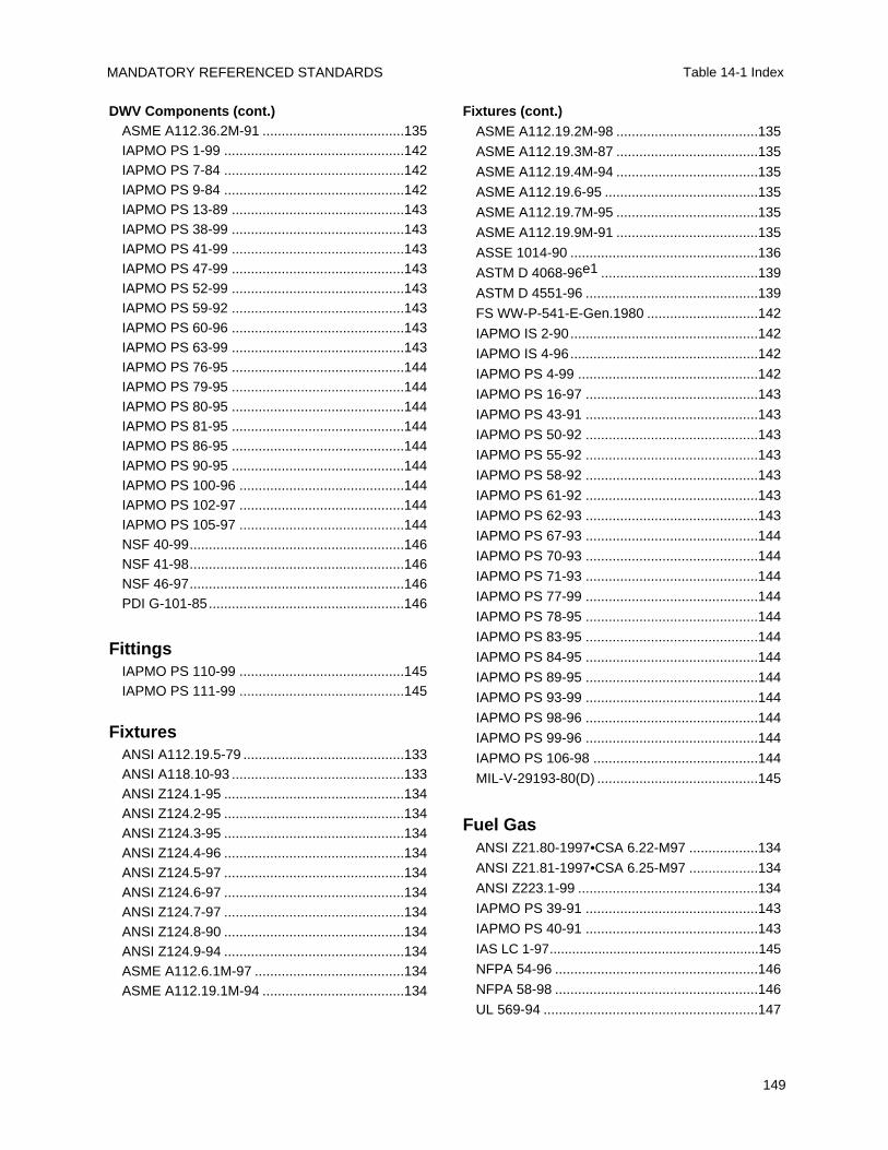
MANDATORY REFERENCED STANDARDS Table 14-1 Index
149
Fixtures (cont.)ASME A112.19.2M-98 .....................................135
ASME A112.19.3M-87 .....................................135
ASME A112.19.4M-94 .....................................135
ASME A112.19.6-95 ........................................135
ASME A112.19.7M-95 .....................................135
ASME A112.19.9M-91 .....................................135
ASSE 1014-90 .................................................136
ASTM D 4068-96e1 .........................................139
ASTM D 4551-96 .............................................139
FS WW-P-541-E-Gen.1980 .............................142
IAPMO IS 2-90.................................................142
IAPMO IS 4-96.................................................142
IAPMO PS 4-99 ...............................................142
IAPMO PS 16-97 .............................................143
IAPMO PS 43-91 .............................................143
IAPMO PS 50-92 .............................................143
IAPMO PS 55-92 .............................................143
IAPMO PS 58-92 .............................................143
IAPMO PS 61-92 .............................................143
IAPMO PS 62-93 .............................................143
IAPMO PS 67-93 .............................................144
IAPMO PS 70-93 .............................................144
IAPMO PS 71-93 .............................................144
IAPMO PS 77-99 .............................................144
IAPMO PS 78-95 .............................................144
IAPMO PS 83-95 .............................................144
IAPMO PS 84-95 .............................................144
IAPMO PS 89-95 .............................................144
IAPMO PS 93-99 .............................................144
IAPMO PS 98-96 .............................................144
IAPMO PS 99-96 .............................................144
IAPMO PS 106-98 ...........................................144
MIL-V-29193-80(D) ..........................................145
Fuel GasANSI Z21.80-1997•CSA 6.22-M97 ..................134
ANSI Z21.81-1997•CSA 6.25-M97 ..................134
ANSI Z223.1-99 ...............................................134
IAPMO PS 39-91 .............................................143
IAPMO PS 40-91 .............................................143
IAS LC 1-97........................................................145
NFPA 54-96 .....................................................146
NFPA 58-98 .....................................................146
UL 569-94 ........................................................147
DWV Components (cont.)ASME A112.36.2M-91 .....................................135IAPMO PS 1-99 ...............................................142IAPMO PS 7-84 ...............................................142IAPMO PS 9-84 ...............................................142IAPMO PS 13-89 .............................................143IAPMO PS 38-99 .............................................143IAPMO PS 41-99 .............................................143IAPMO PS 47-99 .............................................143IAPMO PS 52-99 .............................................143IAPMO PS 59-92 .............................................143IAPMO PS 60-96 .............................................143IAPMO PS 63-99 .............................................143IAPMO PS 76-95 .............................................144IAPMO PS 79-95 .............................................144IAPMO PS 80-95 .............................................144IAPMO PS 81-95 .............................................144IAPMO PS 86-95 .............................................144IAPMO PS 90-95 .............................................144IAPMO PS 100-96 ...........................................144IAPMO PS 102-97 ...........................................144IAPMO PS 105-97 ...........................................144NSF 40-99........................................................146NSF 41-98........................................................146NSF 46-97........................................................146PDI G-101-85...................................................146
FittingsIAPMO PS 110-99 ...........................................145IAPMO PS 111-99 ...........................................145
FixturesANSI A112.19.5-79 ..........................................133ANSI A118.10-93 .............................................133ANSI Z124.1-95 ...............................................134ANSI Z124.2-95 ...............................................134ANSI Z124.3-95 ...............................................134ANSI Z124.4-96 ...............................................134ANSI Z124.5-97 ...............................................134ANSI Z124.6-97 ...............................................134ANSI Z124.7-97 ...............................................134ANSI Z124.8-90 ...............................................134ANSI Z124.9-94 ...............................................134ASME A112.6.1M-97 .......................................134ASME A112.19.1M-94 .....................................134
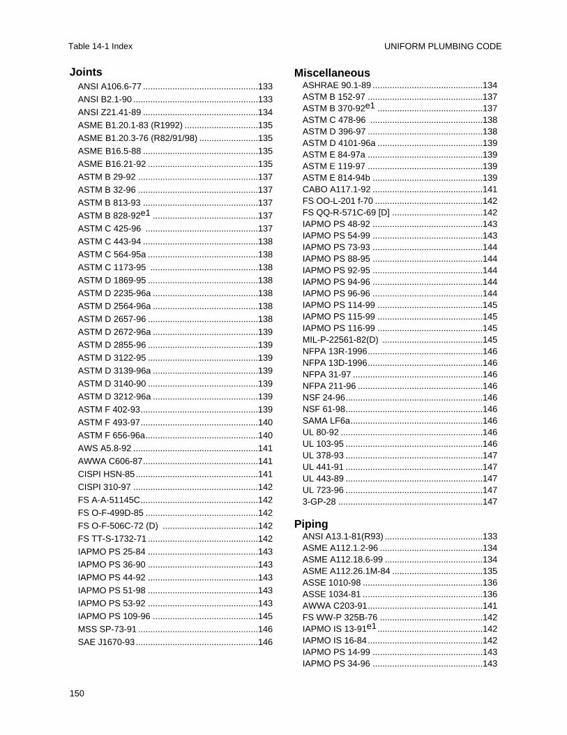
UNIFORM PLUMBING CODE
150
Table 14-1 Index
MiscellaneousASHRAE 90.1-89 .............................................134ASTM B 152-97 ...............................................137ASTM B 370-92e1 ...........................................137ASTM C 478-96 ..............................................138ASTM D 396-97 ...............................................138ASTM D 4101-96a ...........................................139ASTM E 84-97a ...............................................139ASTM E 119-97 ...............................................139ASTM E 814-94b .............................................139CABO A117.1-92 .............................................141FS OO-L-201 f-70 ............................................142FS QQ-R-571C-69 [D] .....................................142IAPMO PS 48-92 .............................................143IAPMO PS 54-99 .............................................143IAPMO PS 73-93 .............................................144IAPMO PS 88-95 .............................................144IAPMO PS 92-95 .............................................144IAPMO PS 94-96 .............................................144IAPMO PS 96-96 .............................................144IAPMO PS 114-99 ...........................................145IAPMO PS 115-99 ...........................................145IAPMO PS 116-99 ...........................................145MIL-P-22561-82(D) .........................................145NFPA 13R-1996...............................................146NFPA 13D-1996...............................................146NFPA 31-97 .....................................................146NFPA 211-96 ...................................................146NSF 24-96........................................................146NSF 61-98........................................................146SAMA LF6a......................................................146UL 80-92 ..........................................................146UL 103-95 ........................................................146UL 378-93 ........................................................147UL 441-91 ........................................................147UL 443-89 ........................................................147UL 723-96 ........................................................1473-GP-28 ...........................................................147
PipingANSI A13.1-81(R93) ........................................133ASME A112.1.2-96 ..........................................134ASME A112.18.6-99 ........................................134ASME A112.26.1M-84 .....................................135ASSE 1010-98 .................................................136ASSE 1034-81 .................................................136AWWA C203-91...............................................141FS WW-P 325B-76 ..........................................142IAPMO IS 13-91e1...........................................142IAPMO IS 16-84...............................................142IAPMO PS 14-99 .............................................143IAPMO PS 34-96 .............................................143
JointsANSI A106.6-77 ...............................................133
ANSI B2.1-90 ...................................................133
ANSI Z21.41-89 ...............................................134
ASME B1.20.1-83 (R1992) ..............................135
ASME B1.20.3-76 (R82/91/98) ........................135
ASME B16.5-88 ...............................................135
ASME B16.21-92 .............................................135
ASTM B 29-92 .................................................137
ASTM B 32-96 .................................................137
ASTM B 813-93 ...............................................137
ASTM B 828-92e1 ...........................................137
ASTM C 425-96 ..............................................137
ASTM C 443-94 ...............................................138
ASTM C 564-95a .............................................138
ASTM C 1173-95 ............................................138
ASTM D 1869-95 .............................................138
ASTM D 2235-96a ...........................................138
ASTM D 2564-96a ...........................................138
ASTM D 2657-96 .............................................138
ASTM D 2672-96a ...........................................139
ASTM D 2855-96 .............................................139
ASTM D 3122-95 .............................................139
ASTM D 3139-96a ...........................................139
ASTM D 3140-90 .............................................139
ASTM D 3212-96a ...........................................139
ASTM F 402-93................................................139
ASTM F 493-97................................................140
ASTM F 656-96a..............................................140
AWS A5.8-92 ...................................................141
AWWA C606-87...............................................141
CISPI HSN-85..................................................141
CISPI 310-97 ...................................................142
FS A-A-51145C................................................142
FS O-F-499D-85 ..............................................142
FS O-F-506C-72 (D) .......................................142
FS TT-S-1732-71 .............................................142
IAPMO PS 25-84 .............................................143
IAPMO PS 36-90 .............................................143
IAPMO PS 44-92 .............................................143
IAPMO PS 51-98 .............................................143
IAPMO PS 53-92 .............................................143
IAPMO PS 109-96 ...........................................145
MSS SP-73-91 .................................................146
SAE J1670-93..................................................146
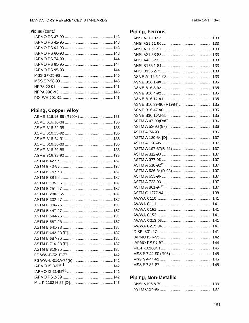
MANDATORY REFERENCED STANDARDS Table 14-1 Index
151
Piping, FerrousANSI A21.10-93 ...............................................133ANSI A21.11-90 ...............................................133ANSI A21.51-91 ...............................................133ANSI A21.53-88 ...............................................133ANSI A40.3-93 .................................................133ANSI B125.1-84 ...............................................133ANSI B125.2-72 ...............................................133ASME A112.3.1-93 ..........................................133ASME B16.1-89 ...............................................135ASME B16.3-92 ...............................................135ASME B16.4-92 ...............................................135ASME B16.12-91 .............................................135ASME B16.39-86 (R1994) ...............................135ASME B16.47-90 .............................................135ASME B36.10M-85 ..........................................135ASTM A 47-90(R95) ........................................136ASTM A 53-96 (97) ..........................................136ASTM A 74-98 .................................................136ASTM A 120-84 [D] ..........................................137ASTM A 126-95 ...............................................137ASTM A 197-87(R-92) .....................................137ASTM A 312-93 ...............................................137ASTM A 377-95 ...............................................137ASTM A 518-92e1 ...........................................137ASTM A 536-84(R-93) .....................................137ASTM A 653-96 ...............................................137ASTM A 733-93 ...............................................137ASTM A 861-94e1 ...........................................137ASTM C 1277-94 ............................................138AWWA C110....................................................141AWWA C111....................................................141AWWA C151....................................................141AWWA C153....................................................141AWWA C213-96...............................................141AWWA C215-94...............................................141CISPI 301-97 ...................................................141IAPMO IS 6-95.................................................142IAPMO PS 97-97 .............................................144MIL-F-18180C1................................................145MSS SP-42-90 (R95) .......................................145MSS SP-44-91 .................................................145MSS SP-83-87 .................................................145
Piping, Non-MetallicANSI A106.6-70 ...............................................133ASTM C 14-95 .................................................137
Piping (cont.)IAPMO PS 37-90 .............................................143IAPMO PS 42-96 .............................................143IAPMO PS 64-98 .............................................143IAPMO PS 66-93 .............................................143IAPMO PS 74-99 .............................................144IAPMO PS 85-95 .............................................144IAPMO PS 95-98 .............................................144MSS SP-25-93 .................................................145MSS SP-58-93 .................................................145NFPA 99-93 .....................................................146NFPA 99C-93...................................................146PDI-WH 201-92................................................146
Piping, Copper AlloyASME B16.15-85 (R1994) ...............................135ASME B16.18-84 .............................................135ASME B16.22-95 .............................................135ASME B16.23-92 .............................................135ASME B16.24-91 .............................................135ASME B16.26-88 .............................................135ASME B16.29-86 .............................................135ASME B16.32-92 .............................................135ASTM B 42-96 .................................................137ASTM B 43-96 .................................................137ASTM B 75-95a ...............................................137ASTM B 88-96 .................................................137ASTM B 135-96 ...............................................137ASTM B 251-97 ...............................................137ASTM B 280-95a .............................................137ASTM B 302-97 ...............................................137ASTM B 306-96 ...............................................137ASTM B 447-97 ...............................................137ASTM B 584-96 ...............................................137ASTM B 587-96 ...............................................137ASTM B 641-93 ...............................................137ASTM B 642-88 [D] ..........................................137ASTM B 687-96 ...............................................137ASTM B 716-93 [D] ..........................................137ASTM B 819-95 ...............................................137FS WW-P-521F-77 ..........................................142FS WW-U-516A-74(b)......................................142IAPMO IS 3-93e1.............................................142IAPMO IS 21-89e1...........................................142IAPMO PS 2-89 ...............................................142MIL-F-1183 H-83 [D] ........................................145
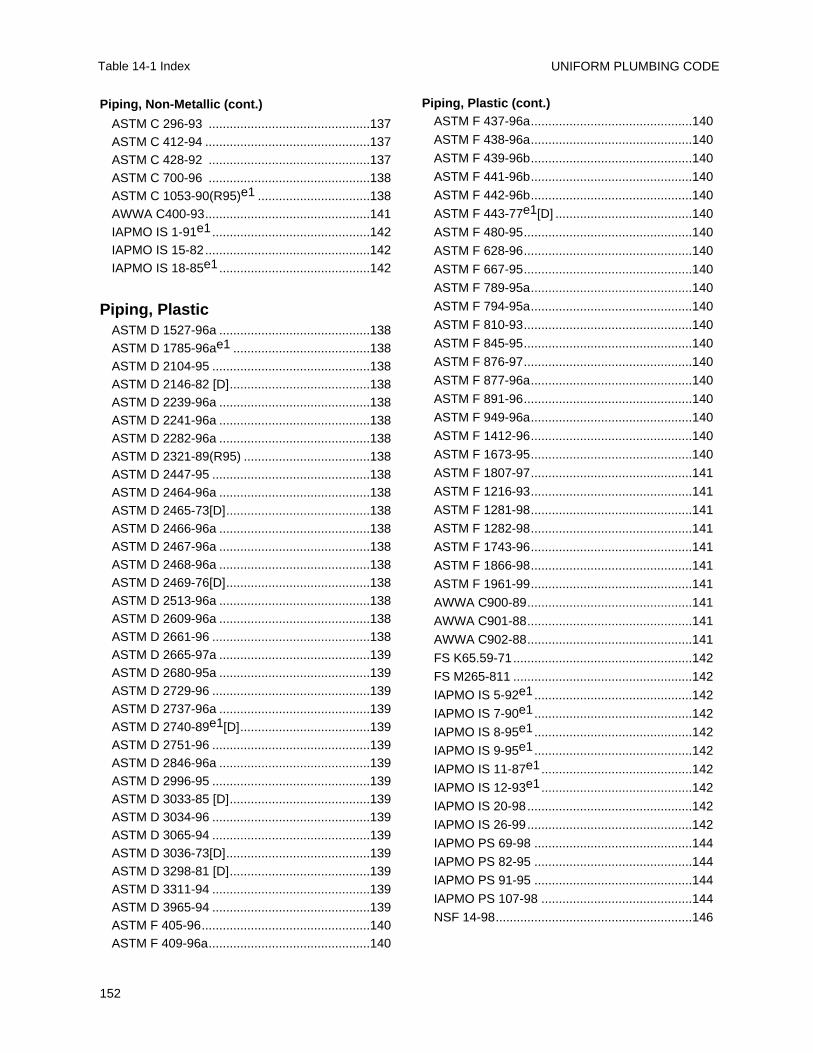
UNIFORM PLUMBING CODE
152
Table 14-1 Index
Piping, Plastic (cont.)ASTM F 437-96a..............................................140
ASTM F 438-96a..............................................140
ASTM F 439-96b..............................................140
ASTM F 441-96b..............................................140
ASTM F 442-96b..............................................140
ASTM F 443-77e1[D] .......................................140
ASTM F 480-95................................................140
ASTM F 628-96................................................140
ASTM F 667-95................................................140
ASTM F 789-95a..............................................140
ASTM F 794-95a..............................................140
ASTM F 810-93................................................140
ASTM F 845-95................................................140
ASTM F 876-97................................................140
ASTM F 877-96a..............................................140
ASTM F 891-96................................................140
ASTM F 949-96a..............................................140
ASTM F 1412-96..............................................140
ASTM F 1673-95..............................................140
ASTM F 1807-97..............................................141
ASTM F 1216-93..............................................141
ASTM F 1281-98..............................................141
ASTM F 1282-98..............................................141
ASTM F 1743-96..............................................141
ASTM F 1866-98..............................................141
ASTM F 1961-99..............................................141
AWWA C900-89...............................................141
AWWA C901-88...............................................141
AWWA C902-88...............................................141
FS K65.59-71...................................................142
FS M265-811 ...................................................142
IAPMO IS 5-92e1.............................................142
IAPMO IS 7-90e1.............................................142
IAPMO IS 8-95e1.............................................142
IAPMO IS 9-95e1.............................................142
IAPMO IS 11-87e1...........................................142
IAPMO IS 12-93e1...........................................142
IAPMO IS 20-98...............................................142
IAPMO IS 26-99...............................................142
IAPMO PS 69-98 .............................................144
IAPMO PS 82-95 .............................................144
IAPMO PS 91-95 .............................................144
IAPMO PS 107-98 ...........................................144
NSF 14-98........................................................146
Piping, Non-Metallic (cont.)
ASTM C 296-93 ..............................................137ASTM C 412-94 ...............................................137ASTM C 428-92 ..............................................137ASTM C 700-96 ..............................................138ASTM C 1053-90(R95)e1 ................................138AWWA C400-93...............................................141IAPMO IS 1-91e1.............................................142IAPMO IS 15-82...............................................142IAPMO IS 18-85e1...........................................142
Piping, PlasticASTM D 1527-96a ...........................................138ASTM D 1785-96ae1 .......................................138ASTM D 2104-95 .............................................138ASTM D 2146-82 [D]........................................138ASTM D 2239-96a ...........................................138ASTM D 2241-96a ...........................................138ASTM D 2282-96a ...........................................138ASTM D 2321-89(R95) ....................................138ASTM D 2447-95 .............................................138ASTM D 2464-96a ...........................................138ASTM D 2465-73[D].........................................138ASTM D 2466-96a ...........................................138ASTM D 2467-96a ...........................................138ASTM D 2468-96a ...........................................138ASTM D 2469-76[D].........................................138ASTM D 2513-96a ...........................................138ASTM D 2609-96a ...........................................138ASTM D 2661-96 .............................................138ASTM D 2665-97a ...........................................139ASTM D 2680-95a ...........................................139ASTM D 2729-96 .............................................139ASTM D 2737-96a ...........................................139ASTM D 2740-89e1[D].....................................139ASTM D 2751-96 .............................................139ASTM D 2846-96a ...........................................139ASTM D 2996-95 .............................................139ASTM D 3033-85 [D]........................................139ASTM D 3034-96 .............................................139ASTM D 3065-94 .............................................139ASTM D 3036-73[D].........................................139ASTM D 3298-81 [D]........................................139ASTM D 3311-94 .............................................139ASTM D 3965-94 .............................................139ASTM F 405-96................................................140ASTM F 409-96a..............................................140
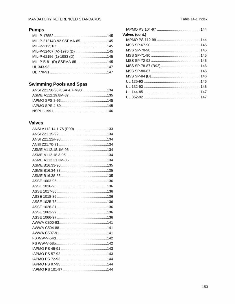
MANDATORY REFERENCED STANDARDS Table 14-1 Index
153
IAPMO PS 104-97 ...........................................144Valves (cont.)
IAPMO PS 112-99 ...........................................144MSS SP-67-90 .................................................145MSS SP-70-90 .................................................145MSS SP-71-90 .................................................145MSS SP-72-92 .................................................146MSS SP-78-87 (R92) .......................................146MSS SP-80-87 .................................................146MSS SP-84 [D].................................................146UL 125-93 ........................................................146UL 132-93 ........................................................146UL 144-85 ........................................................147UL 352-92 ........................................................147
PumpsMIL-P-17552 ....................................................145MIL-P-21214B-92 SSPMA-85..........................145MIL-P-21251C..................................................145MIL-P-52407 (A)-1976 (D) ..............................145MIL-P-62156 (1)-1983 (D) ...............................145MIL-P-B-81 (D) SSPMA-85..............................145UL 343-93 ........................................................147UL 778-91 ........................................................147
Swimming Pools and SpasANSI Z21.56-98•CSA 4.7-M98 ........................134ASME A112.19.8M-87 .....................................135IAPMO SPS 3-93 .............................................145IAPMO SPS 4-89 .............................................145NSPI 1-1991 ....................................................146
ValvesANSI A112.14.1-75 (R90) ................................133ANSI Z21.15-92 ...............................................134ANSI Z21.22a-90 .............................................134ANSI Z21.70-81 ...............................................134ASME A112.18.1M-96 .....................................134ASME A112.18.3-96 ........................................134ASME A112.21.3M-85 .....................................134ASME B16.33-90 .............................................135ASME B16.34-88 .............................................135ASME B16.38-85 .............................................135ASSE 1003-95 .................................................136ASSE 1016-96 .................................................136ASSE 1017-86 .................................................136ASSE 1018-86 .................................................136ASSE 1025-78 .................................................136ASSE 1028-81 .................................................136ASSE 1062-97 .................................................136ASSE 1066-97 .................................................136AWWA C500-93...............................................141AWWA C504-88...............................................141AWWA C507-91...............................................141FS WW-V-54d..................................................142FS WW-V-58b..................................................142IAPMO PS 45-91 .............................................143IAPMO PS 57-92 .............................................143IAPMO PS 72-93 .............................................144IAPMO PS 87-95 .............................................144IAPMO PS 101-97 ...........................................144
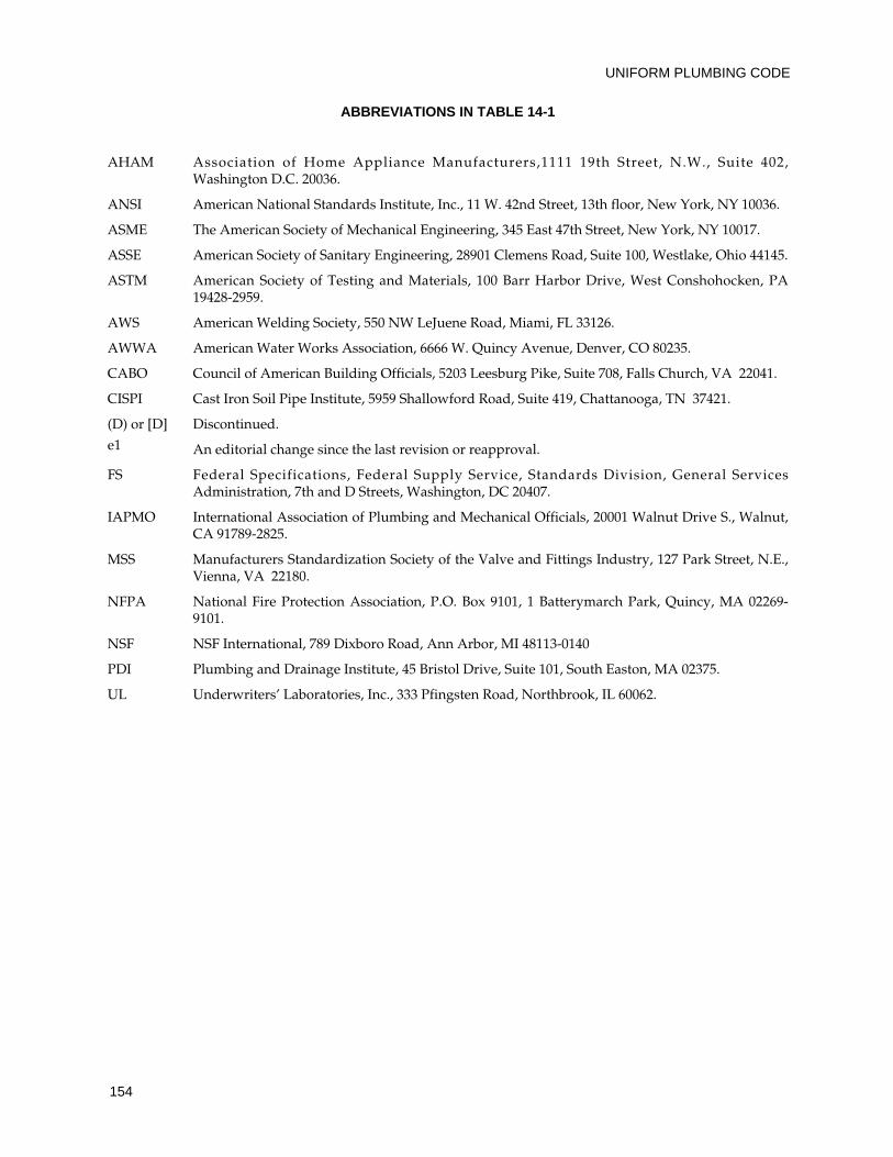
UNIFORM PLUMBING CODE
154
ABBREVIATIONS IN TABLE 14-1
AHAM Association of Home Appliance Manufacturers,1111 19th Street, N.W., Suite 402, Washington D.C. 20036.
ANSI American National Standards Institute, Inc., 11 W. 42nd Street, 13th floor, New York, NY 10036.
ASME The American Society of Mechanical Engineering, 345 East 47th Street, New York, NY 10017.
ASSE American Society of Sanitary Engineering, 28901 Clemens Road, Suite 100, Westlake, Ohio 44145.
ASTM American Society of Testing and Materials, 100 Barr Harbor Drive, West Conshohocken, PA19428-2959.
AWS American Welding Society, 550 NW LeJuene Road, Miami, FL 33126.
AWWA American Water Works Association, 6666 W. Quincy Avenue, Denver, CO 80235.
CABO Council of American Building Officials, 5203 Leesburg Pike, Suite 708, Falls Church, VA 22041.
CISPI Cast Iron Soil Pipe Institute, 5959 Shallowford Road, Suite 419, Chattanooga, TN 37421.
(D) or [D] Discontinued.e1 An editorial change since the last revision or reapproval.
FS Federal Specifications, Federal Supply Service, Standards Division, General ServicesAdministration, 7th and D Streets, Washington, DC 20407.
IAPMO International Association of Plumbing and Mechanical Officials, 20001 Walnut Drive S., Walnut,CA 91789-2825.
MSS Manufacturers Standardization Society of the Valve and Fittings Industry, 127 Park Street, N.E.,Vienna, VA 22180.
NFPA National Fire Protection Association, P.O. Box 9101, 1 Batterymarch Park, Quincy, MA 02269-9101.
NSF NSF International, 789 Dixboro Road, Ann Arbor, MI 48113-0140
PDI Plumbing and Drainage Institute, 45 Bristol Drive, Suite 101, South Easton, MA 02375.
UL Underwriters’ Laboratories, Inc., 333 Pfingsten Road, Northbrook, IL 60062.
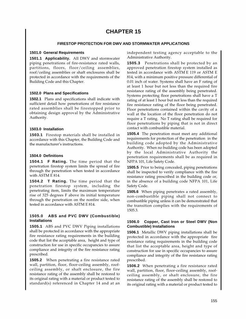
155
1501.0 General Requirements
1501.1 Applicability. All DWV and stormwaterpiping penetrations of fire-resistance rated walls,partitions, floors, floor/ceiling assemblies,roof/ceiling assemblies or shaft enclosures shall beprotected in accordance with the requirements of theBuilding Code and this Chapter.
1502.0 Plans and Specifications
1502.1 Plans and specifications shall indicate withsufficient detail how penetrations of fire resistancerated assemblies shall be firestopped prior toobtaining design approval by the AdministrativeAuthority.
1503.0 Installation
1503.1 Firestop materials shall be installed inaccordance with this Chapter, the Building Code andthe manufacturer’s instructions.
1504.0 Definitions
1504.1 F Rating. The time period that thepenetration firestop system limits the spread of firethrough the penetration when tested in accordancewith ASTM E 814.
1504.2 T Rating. The time period that thepenetration firestop system, including thepenetrating item, limits the maximum temperaturerise of 325 degrees F above its initial temperaturethrough the penetration on the nonfire side, whentested in accordance with ASTM E 814.
1505.0 ABS and PVC DWV (Combustible)Installations
1505.1 ABS and PVC DWV Piping installationsshall be protected in accordance with the appropriatefire resistance rating requirements in the buildingcode that list the acceptable area, height and type ofconstruction for use in specific occupancies to assurecompliance and integrity of the fire resistance ratingprescribed.
1505.2 When penetrating a fire resistance ratedwall, partition, floor, floor-ceiling assembly, roof-ceiling assembly, or shaft enclosure, the fireresistance rating of the assembly shall be restored toits original rating with a material or product tested tostandard(s) referenced in Chapter 14 and at an
independent testing agency acceptable to theAdministrative Authority.
1505.3 Penetrations shall be protected by anapproved penetration firestop system installed astested in accordance with ASTM E 119 or ASTM E814, with a minimum positive pressure differential of0.01 inch of water. Systems shall have an F rating ofat least 1 hour but not less than the required fireresistance rating of the assembly being penetrated.Systems protecting floor penetrations shall have a Trating of at least 1 hour but not less than the requiredfire resistance rating of the floor being penetrated.Floor penetrations contained within the cavity of awall at the location of the floor penetration do notrequire a T rating. No T rating shall be required forfloor penetrations by piping that is not in directcontact with combustible material.
1505.4 The penetration must meet any additionalrequirements for protection of the penetration in thebuilding code adopted by the AdministrativeAuthority. When no building code has been adoptedby the local Administrative Authority thepenetration requirements shall be as required inNFPA 101, Life Safety Code.
1505.5 Prior to being concealed, piping penetrationsshall be inspected to verify compliance with the fireresistance rating prescribed in the building code or,in the absence of a building code NFPA 101, LifeSafety Code.
1505.6 When piping penetrates a rated assembly,non-combustible piping shall not connect tocombustible piping unless it can be demonstrated thatthe transition complies with the requirements of1505.3.
1506.0 Copper, Cast Iron or Steel DWV (NonCombustible) Installations
1506.1 Metallic DWV piping installations shall beprotected in accordance with the appropriate fireresistance rating requirements in the building codethat list the acceptable area, height and type ofconstruction for use in specific occupancies to assurecompliance and integrity of the fire resistance ratingprescribed.
1506.2 When penetrating a fire resistance ratedwall, partition, floor, floor-ceiling assembly, roof-ceiling assembly, or shaft enclosure, the fireresistance rating of the assembly shall be restored toits original rating with a material or product tested to
CHAPTER 15
FIRESTOP PROTECTION FOR DWV AND STORMWATER APPLICATIONS
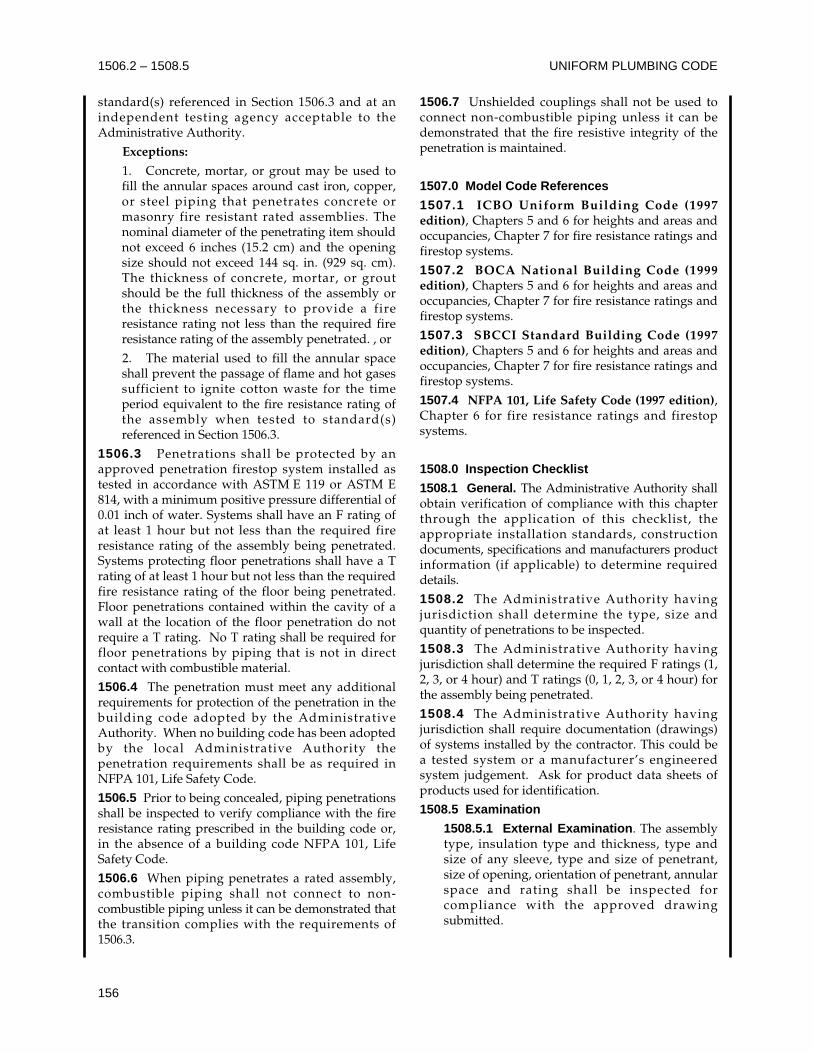
UNIFORM PLUMBING CODE1506.2 – 1508.5
156
standard(s) referenced in Section 1506.3 and at anindependent testing agency acceptable to theAdministrative Authority.
Exceptions:
1. Concrete, mortar, or grout may be used tofill the annular spaces around cast iron, copper,or steel piping that penetrates concrete ormasonry fire resistant rated assemblies. Thenominal diameter of the penetrating item shouldnot exceed 6 inches (15.2 cm) and the openingsize should not exceed 144 sq. in. (929 sq. cm).The thickness of concrete, mortar, or groutshould be the full thickness of the assembly orthe thickness necessary to provide a fireresistance rating not less than the required fireresistance rating of the assembly penetrated. , or
2. The material used to fill the annular spaceshall prevent the passage of flame and hot gasessufficient to ignite cotton waste for the timeperiod equivalent to the fire resistance rating ofthe assembly when tested to standard(s)referenced in Section 1506.3.
1506.3 Penetrations shall be protected by anapproved penetration firestop system installed astested in accordance with ASTM E 119 or ASTM E814, with a minimum positive pressure differential of0.01 inch of water. Systems shall have an F rating ofat least 1 hour but not less than the required fireresistance rating of the assembly being penetrated.Systems protecting floor penetrations shall have a Trating of at least 1 hour but not less than the requiredfire resistance rating of the floor being penetrated.Floor penetrations contained within the cavity of awall at the location of the floor penetration do notrequire a T rating. No T rating shall be required forfloor penetrations by piping that is not in directcontact with combustible material.
1506.4 The penetration must meet any additionalrequirements for protection of the penetration in thebuilding code adopted by the AdministrativeAuthority. When no building code has been adoptedby the local Administrative Authority thepenetration requirements shall be as required inNFPA 101, Life Safety Code.
1506.5 Prior to being concealed, piping penetrationsshall be inspected to verify compliance with the fireresistance rating prescribed in the building code or,in the absence of a building code NFPA 101, LifeSafety Code.
1506.6 When piping penetrates a rated assembly,combustible piping shall not connect to non-combustible piping unless it can be demonstrated thatthe transition complies with the requirements of1506.3.
1506.7 Unshielded couplings shall not be used toconnect non-combustible piping unless it can bedemonstrated that the fire resistive integrity of thepenetration is maintained.
1507.0 Model Code References
1507.1 ICBO Uniform Building Code (1997edition), Chapters 5 and 6 for heights and areas andoccupancies, Chapter 7 for fire resistance ratings andfirestop systems.
1507.2 BOCA National Building Code (1999edition), Chapters 5 and 6 for heights and areas andoccupancies, Chapter 7 for fire resistance ratings andfirestop systems.
1507.3 SBCCI Standard Building Code (1997edition), Chapters 5 and 6 for heights and areas andoccupancies, Chapter 7 for fire resistance ratings andfirestop systems.
1507.4 NFPA 101, Life Safety Code (1997 edition),Chapter 6 for fire resistance ratings and firestopsystems.
1508.0 Inspection Checklist
1508.1 General. The Administrative Authority shallobtain verification of compliance with this chapterthrough the application of this checklist, theappropriate installation standards, constructiondocuments, specifications and manufacturers productinformation (if applicable) to determine requireddetails.
1508.2 The Administrative Authority havingjurisdiction shall determine the type, size andquantity of penetrations to be inspected.
1508.3 The Administrative Authority havingjurisdiction shall determine the required F ratings (1,2, 3, or 4 hour) and T ratings (0, 1, 2, 3, or 4 hour) forthe assembly being penetrated.
1508.4 The Administrative Authority havingjurisdiction shall require documentation (drawings)of systems installed by the contractor. This could bea tested system or a manufacturer’s engineeredsystem judgement. Ask for product data sheets ofproducts used for identification.
1508.5 Examination
1508.5.1 External Examination. The assemblytype, insulation type and thickness, type andsize of any sleeve, type and size of penetrant,size of opening, orientation of penetrant, annularspace and rating shall be inspected forcompliance with the approved drawingsubmitted.
FIRESTOP PROTECTION FOR DWV AND STORMWATER APPLICATIONS 1508.5
157
1508.5.2 Internal Examination. Withcontractor present and prepared to make repairs,the contractor shall be directed to cut into thefirestop sufficiently to reveal the type andbacking materials and the type and amount ofthe material. The contractor shall repair thefirestop and the Administrative Authorityhaving jurisdiction shall re-examine theinstallation.
1508.5.3 The Administrative Authority havingjurisdication after examining the firestop, bothexternally and internally, shall compare thevalues with the design submitted. TheAdministrative Authority having jurisdicationwill verify that all values fall within the designparameters of the tested or engineered systemsubmitted and approved.
1508.5.4 The Administrative Authority havingjurisdiction shall continue inspection approvingor rejecting applications as required. If sufficientnon-compliant installations are found, the entireproject may need to be redone. Re-examinationafter corrections shall be made.

UNIFORM PLUMBING CODE
158

159
APPENDICES
The appendices are intended to supplement the provisions of the installation requirements of this Code. Thedefinitions in Chapter 2 are also applicable to the appendices.
TABLE OF CONTENTS
Page
Appendix A
Recommended Rules for Sizing the Water Supply System ............................................................... 161
Appendix B
Explanatory Notes on Combination Waste and Vent Systems .......................................................... 177
Appendix C
Sizing of Categoy I Venting Systems ................................................................................................. 179
Appendix D
Sizing Stormwater Drainage Systems................................................................................................ 199
Appendix E
Manufactured/Mobile Home Parks and Recreational Vehicle Parks.................................................. 207
Appendix F
Reserved
Appendix G
Graywater Systems for Single Family Dwellings................................................................................ 215
Appendix H
Recommended Procedures for Design, Construction and Installation of Commercial
Kitchen Grease Interceptors............................................................................................................... 225
Appendix I
Installation Standards......................................................................................................................... 229
Appendix J
Reclaimed Water Systems for Non-Residential Buildings.................................................................. 325
Appendix K
Private Sewage Disposal Systems..................................................................................................... 329
Appendix L
Alternate Plumbing Systems .............................................................................................................. 341

UNIFORM PLUMBING CODE
160
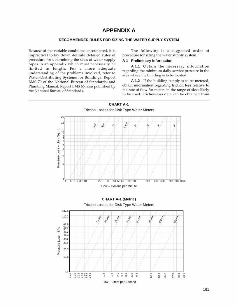
161
Because of the variable conditions encountered, it isimpractical to lay down definite detailed rules ofprocedure for determining the sizes of water supplypipes in an appendix which must necessarily belimited in length. For a more adequateunderstanding of the problems involved, refer toWater-Distributing Systems for Buildings, ReportBMS 79 of the National Bureau of Standards; andPlumbing Manual, Report BMS 66, also published bythe National Bureau of Standards.
The following is a suggested order ofprocedure for sizing the water supply system.
A 1 Preliminary Information
A 1.1 Obtain the necessary informationregarding the minimum daily service pressure in thearea where the building is to be located.
A 1.2 If the building supply is to be metered,obtain information regarding friction loss relative tothe rate of flow for meters in the range of sizes likelyto be used. Friction-loss data can be obtained from
CHART A-1
Friction Losses for Disk Type Water Meters
Flow – Gallons per Minute
CHART A-1 (Metric)
Friction Losses for Disk Type Water Meters
Flow – Liters per Second
20
16
109876
5
4
3
2
14 5 6 7 8 9 10 20 30 40 50 60 80 100 200 300 400 600 800 1000
5/8"
3/4" 1"
1-1/
2"
2" 3" 4" 5"
Pre
ssur
e Lo
ss –
Lbs
./ S
q. In
.
137.8
110.2
68.962.055.148.241.3
34.5
27.6
20.7
13.8
6.9
0.25
18 m
m
20 m
m
25 m
m
40 m
m
50 m
m
80 m
m
100
mm
125
mm
0.32
0.38
0.50
0.63
0.57 1.3
1.9
2.5
3.2
3.8
5.0
12.6
18.9
25.2
37.8
50.4
63.06.3
0.44
Pre
ssur
e Lo
ss –
kP
a
APPENDIX A
RECOMMENDED RULES FOR SIZING THE WATER SUPPLY SYSTEM
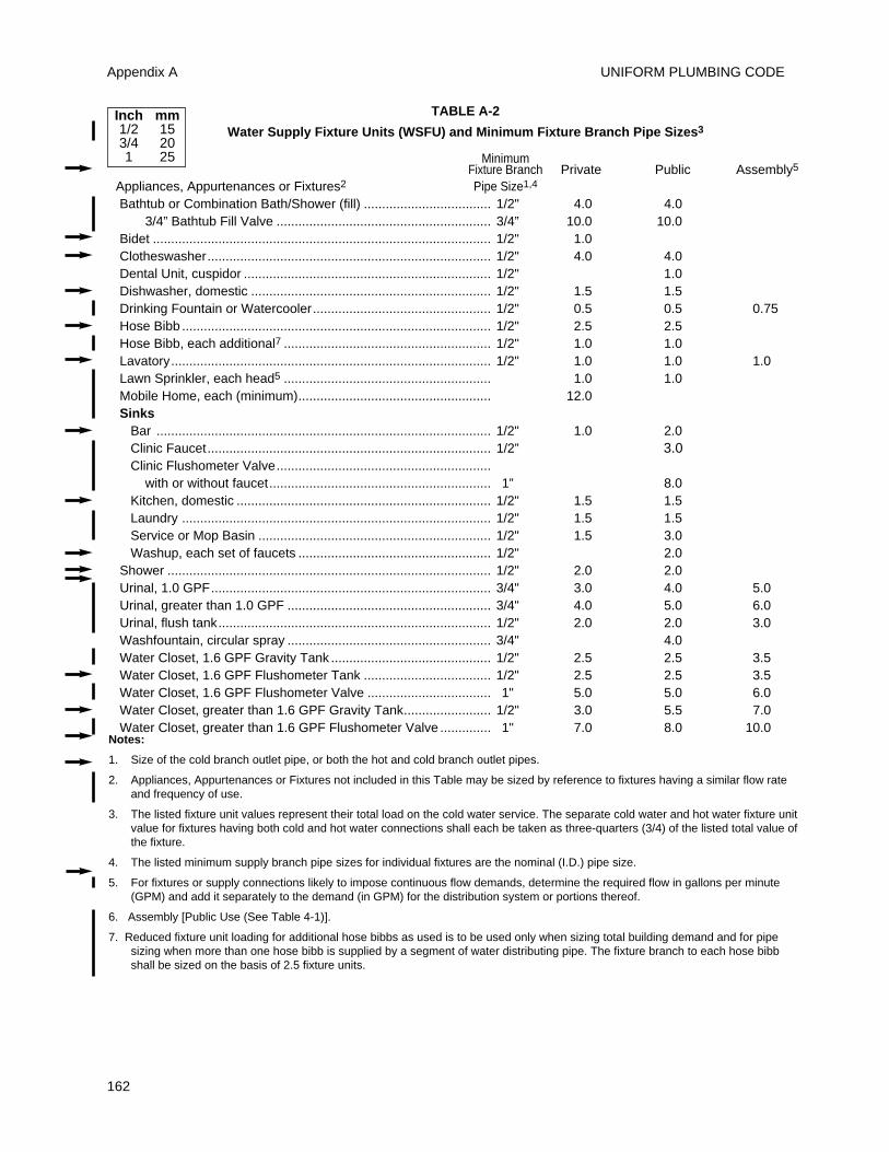
UNIFORM PLUMBING CODEAppendix A
162
TABLE A-2
Water Supply Fixture Units (WSFU) and Minimum Fixture Branch Pipe Sizes3
MinimumFixture Branch Private Public Assembly5
Appliances, Appurtenances or Fixtures2 Pipe Size1,4
Bathtub or Combination Bath/Shower (fill) ................................... 1/2" 4.0 4.03/4” Bathtub Fill Valve ........................................................... 3/4” 10.0 10.0
Bidet ............................................................................................. 1/2" 1.0Clotheswasher.............................................................................. 1/2" 4.0 4.0Dental Unit, cuspidor .................................................................... 1/2" 1.0Dishwasher, domestic .................................................................. 1/2" 1.5 1.5Drinking Fountain or Watercooler................................................. 1/2" 0.5 0.5 0.75Hose Bibb ..................................................................................... 1/2" 2.5 2.5Hose Bibb, each additional7 ......................................................... 1/2" 1.0 1.0Lavatory........................................................................................ 1/2" 1.0 1.0 1.0Lawn Sprinkler, each head5 ......................................................... 1.0 1.0Mobile Home, each (minimum)..................................................... 12.0Sinks
Bar ............................................................................................ 1/2" 1.0 2.0Clinic Faucet.............................................................................. 1/2” 3.0Clinic Flushometer Valve...........................................................
with or without faucet............................................................. 1” 8.0Kitchen, domestic ...................................................................... 1/2" 1.5 1.5Laundry ..................................................................................... 1/2" 1.5 1.5Service or Mop Basin ................................................................ 1/2" 1.5 3.0Washup, each set of faucets ..................................................... 1/2" 2.0
Shower ......................................................................................... 1/2" 2.0 2.0Urinal, 1.0 GPF............................................................................. 3/4" 3.0 4.0 5.0Urinal, greater than 1.0 GPF ........................................................ 3/4" 4.0 5.0 6.0Urinal, flush tank........................................................................... 1/2" 2.0 2.0 3.0Washfountain, circular spray ........................................................ 3/4" 4.0Water Closet, 1.6 GPF Gravity Tank ............................................ 1/2" 2.5 2.5 3.5Water Closet, 1.6 GPF Flushometer Tank ................................... 1/2" 2.5 2.5 3.5Water Closet, 1.6 GPF Flushometer Valve .................................. 1" 5.0 5.0 6.0Water Closet, greater than 1.6 GPF Gravity Tank........................ 1/2" 3.0 5.5 7.0Water Closet, greater than 1.6 GPF Flushometer Valve .............. 1" 7.0 8.0 10.0
Notes:
1. Size of the cold branch outlet pipe, or both the hot and cold branch outlet pipes.
2. Appliances, Appurtenances or Fixtures not included in this Table may be sized by reference to fixtures having a similar flow rateand frequency of use.
3. The listed fixture unit values represent their total load on the cold water service. The separate cold water and hot water fixture unitvalue for fixtures having both cold and hot water connections shall each be taken as three-quarters (3/4) of the listed total value ofthe fixture.
4. The listed minimum supply branch pipe sizes for individual fixtures are the nominal (I.D.) pipe size.
5. For fixtures or supply connections likely to impose continuous flow demands, determine the required flow in gallons per minute(GPM) and add it separately to the demand (in GPM) for the distribution system or portions thereof.
6. Assembly [Public Use (See Table 4-1)].
7. Reduced fixture unit loading for additional hose bibbs as used is to be used only when sizing total building demand and for pipesizing when more than one hose bibb is supplied by a segment of water distributing pipe. The fixture branch to each hose bibbshall be sized on the basis of 2.5 fixture units.
Inch mm1/2 153/4 201 25
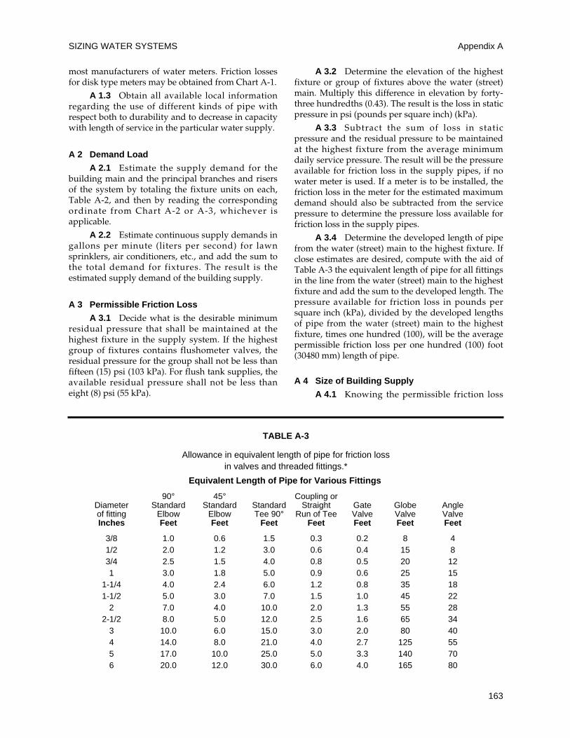
SIZING WATER SYSTEMS
163
most manufacturers of water meters. Friction lossesfor disk type meters may be obtained from Chart A-1.
A 1.3 Obtain all available local informationregarding the use of different kinds of pipe withrespect both to durability and to decrease in capacitywith length of service in the particular water supply.
A 2 Demand Load
A 2.1 Estimate the supply demand for thebuilding main and the principal branches and risersof the system by totaling the fixture units on each,Table A-2, and then by reading the correspondingordinate from Chart A-2 or A-3, whichever isapplicable.
A 2.2 Estimate continuous supply demands ingallons per minute (liters per second) for lawnsprinklers, air conditioners, etc., and add the sum tothe total demand for fixtures. The result is theestimated supply demand of the building supply.
A 3 Permissible Friction Loss
A 3.1 Decide what is the desirable minimumresidual pressure that shall be maintained at thehighest fixture in the supply system. If the highestgroup of fixtures contains flushometer valves, theresidual pressure for the group shall not be less thanfifteen (15) psi (103 kPa). For flush tank supplies, theavailable residual pressure shall not be less thaneight (8) psi (55 kPa).
A 3.2 Determine the elevation of the highestfixture or group of fixtures above the water (street)main. Multiply this difference in elevation by forty-three hundredths (0.43). The result is the loss in staticpressure in psi (pounds per square inch) (kPa).
A 3.3 Subtract the sum of loss in staticpressure and the residual pressure to be maintainedat the highest fixture from the average minimumdaily service pressure. The result will be the pressureavailable for friction loss in the supply pipes, if nowater meter is used. If a meter is to be installed, thefriction loss in the meter for the estimated maximumdemand should also be subtracted from the servicepressure to determine the pressure loss available forfriction loss in the supply pipes.
A 3.4 Determine the developed length of pipefrom the water (street) main to the highest fixture. Ifclose estimates are desired, compute with the aid ofTable A-3 the equivalent length of pipe for all fittingsin the line from the water (street) main to the highestfixture and add the sum to the developed length. Thepressure available for friction loss in pounds persquare inch (kPa), divided by the developed lengthsof pipe from the water (street) main to the highestfixture, times one hundred (100), will be the averagepermissible friction loss per one hundred (100) foot(30480 mm) length of pipe.
A 4 Size of Building Supply
A 4.1 Knowing the permissible friction loss
Appendix A
TABLE A-3
Allowance in equivalent length of pipe for friction lossin valves and threaded fittings.*
Equivalent Length of Pipe for Various Fittings
90° 45° Coupling orDiameter Standard Standard Standard Straight Gate Globe Angleof fitting Elbow Elbow Tee 90° Run of Tee Valve Valve ValveInches Feet Feet Feet Feet Feet Feet Feet
3/8 1.0 0.6 1.5 0.3 0.2 8 41/2 2.0 1.2 3.0 0.6 0.4 15 83/4 2.5 1.5 4.0 0.8 0.5 20 121 3.0 1.8 5.0 0.9 0.6 25 15
1-1/4 4.0 2.4 6.0 1.2 0.8 35 181-1/2 5.0 3.0 7.0 1.5 1.0 45 22
2 7.0 4.0 10.0 2.0 1.3 55 282-1/2 8.0 5.0 12.0 2.5 1.6 65 34
3 10.0 6.0 15.0 3.0 2.0 80 404 14.0 8.0 21.0 4.0 2.7 125 555 17.0 10.0 25.0 5.0 3.3 140 706 20.0 12.0 30.0 6.0 4.0 165 80
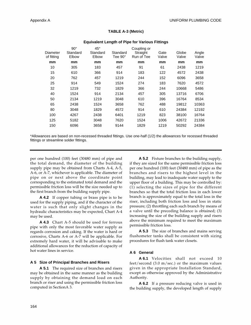
UNIFORM PLUMBING CODE
164
per one hundred (100) feet (30480 mm) of pipe andthe total demand, the diameter of the buildingsupply pipe may be obtained from Charts A-4, A-5,A-6, or A-7, whichever is applicable. The diameter ofpipe on or next above the coordinate pointcorresponding to the estimated total demand and thepermissible friction loss will be the size needed up tothe first branch from the building supply pipe.
A 4.2 If copper tubing or brass pipe is to beused for the supply piping, and if the character of thewater is such that only slight changes in thehydraulic characteristics may be expected, Chart A-4may be used.
A 4.3 Chart A-5 should be used for ferrouspipe with only the most favorable water supply asregards corrosion and caking. If the water is hard orcorrosive, Charts A-6 or A-7 will be applicable. Forextremely hard water, it will be advisable to makeadditional allowances for the reduction of capacity ofhot water lines in service.
A 5 Size of Principal Branches and Risers
A 5.1 The required size of branches and risersmay be obtained in the same manner as the buildingsupply by obtaining the demand load on eachbranch or riser and using the permissible friction losscomputed in SectionA 3.
A 5.2 Fixture branches to the building supply,if they are sized for the same permissible friction lossper one hundred (100) feet (30480 mm) of pipe as thebranches and risers to the highest level in thebuilding, may lead to inadequate water supply to theupper floor of a building. This may be controlled by:(1) selecting the sizes of pipe for the differentbranches so that the total friction loss in each lowerbranch is approximately equal to the total loss in theriser, including both friction loss and loss in staticpressure; (2) throttling each such branch by means ofa valve until the preceding balance is obtained; (3)increasing the size of the building supply and risersabove the minimum required to meet the maximumpermissible friction loss.
A 5.3 The size of branches and mains servingflushometer tanks shall be consistent with sizingprocedures for flush tank water closets.
A 6 General
A 6.1 Velocities shall not exceed 10feet/second (3.0 m/sec.) or the maximum valuesgiven in the appropriate Installation Standard,except as otherwise approved by the AdministrativeAuthority.
A 6.2 If a pressure reducing valve is used inthe building supply, the developed length of supply
Appendix A
TABLE A-3 (Metric)
Equivalent Length of Pipe for Various Fittings
90° 45° Coupling orDiameter Standard Standard Standard Straight Gate Globe Angleof fitting Elbow Elbow Tee 90° Run of Tee Valve Valve Valve
mm mm mm mm mm mm mm mm10 305 183 457 91 61 2438 121915 610 366 914 183 122 4572 243820 762 457 1219 244 152 6096 365825 914 549 1524 274 183 7620 457232 1219 732 1829 366 244 10668 548640 1524 914 2134 457 305 13716 670650 2134 1219 3048 610 396 16764 853465 2438 1524 3658 762 488 19812 1036380 3048 1829 4572 914 610 24384 12192100 4267 2438 6401 1219 823 38100 16764125 5182 3048 7620 1524 1006 42672 21336150 6096 3658 9144 1829 1219 50292 24384
*Allowances are based on non-recessed threaded fittings. Use one-half (1/2) the allowances for recessed threadedfittings or streamline solder fittings.
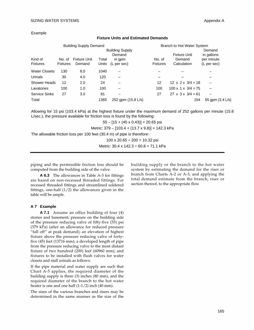
SIZING WATER SYSTEMS
165
piping and the permissible friction loss should becomputed from the building side of the valve.
A 6.3 The allowances in Table A-3 for fittingsare based on non-recessed threaded fittings. Forrecessed threaded fittings and streamlined solderedfittings, one-half (1/2) the allowances given in thetable will be ample.
A 7 Example
A 7.1 Assume an office building of four (4)stories and basement; pressure on the building sideof the pressure reducing valve of fifty-five (55) psi(379 kPa) (after an allowance for reduced pressure“fall off” at peak demand); an elevation of highestfixture above the pressure reducing valve of forty-five (45) feet (13716 mm); a developed length of pipefrom the pressure reducing valve to the most distantfixture of two hundred (200) feet (60960 mm); andfixtures to be installed with flush valves for waterclosets and stall urinals as follows:
If the pipe material and water supply are such thatChart A-5 applies, the required diameter of thebuilding supply is three (3) inches (80 mm), and therequired diameter of the branch to the hot waterheater is one and one half (1-1/2) inch (40 mm).
The sizes of the various branches and risers may bedetermined in the same manner as the size of the
building supply or the branch to the hot watersystem by estimating the demand for the riser orbranch from Charts A-2 or A-3, and applying thetotal demand estimate from the branch, riser orsection thereof, to the appropriate flow
Appendix A
ExampleFixture Units and Estimated Demands
Building Supply Demand Branch to Hot Water SystemBuilding Supply Demand
Demand Fixture Unit in gallonsKind of No. of Fixture Unit Total in gpm No. of Demand per minuteFixtures Fixtures Demand Units (L per sec) Fixtures Calculation (L per sec)
Water Closets 130 8.0 1040 – – – –
Urinals 30 4.0 120 – – – –
Shower Heads 12 2.0 24 – 12 12 x 2 x 3/4 = 18 –
Lavatories 100 1.0 100 – 100 100 x 1 x 3/4 = 75 –
Service Sinks 27 3.0 81 – 27 27 x 3 x 3/4 = 61 –
Total 1365 252 gpm (15.8 L/s) 154 55 gpm (3.4 L/s)
Allowing for 15 psi (103.4 kPa) at the highest fixture under the maximum demand of 252 gallons per minute (15.8L/sec.), the pressure available for friction loss is found by the following:
55 – [15 + (45 x 0.43)] = 20.65 psi
Metric: 379 – [103.4 + (13.7 x 9.8)] = 142.3 kPa
The allowable friction loss per 100 feet (30.4 m) of pipe is therefore:
100 x 20.65 ÷ 200 = 10.32 psi
Metric: 30.4 x 142.3 ÷ 60.8 = 71.1 kPa
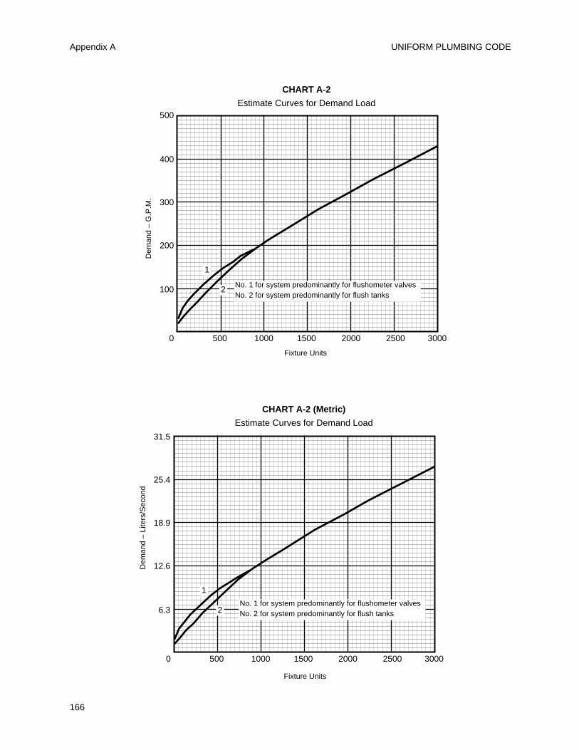
UNIFORM PLUMBING CODE
166
Appendix A
Dem
and
– G
.P.M
.
500
400
300
200
100
0 500 1000 1500 2000 2500 3000
1
2
Fixture Units
Fixture Units
CHART A-2
Estimate Curves for Demand Load
No. 1 for system predominantly for flushometer valvesNo. 2 for system predominantly for flush tanks
Dem
and
– Li
ters
/Sec
ond
31.5
25.4
18.9
12.6
6.3
0 500 1000 1500 2000 2500 3000
1
2
CHART A-2 (Metric)
Estimate Curves for Demand Load
No. 1 for system predominantly for flushometer valvesNo. 2 for system predominantly for flush tanks
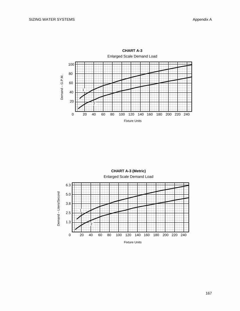
SIZING WATER SYSTEMS
167
Appendix A
Fixture Units
Fixture Units
Dem
and
– G
.P.M
.100
80
60
40
20
0 20 40 60 80 100 120 140 160 180 200 220 240
1
2
CHART A-3
Enlarged Scale Demand LoadD
eman
d –
Lite
rs/S
econ
d
6.3
5.0
3.8
2.5
1.3
0 20 40 60 80 100 120 140 160 180 200 220 240
1
2
CHART A-3 (Metric)
Enlarged Scale Demand Load
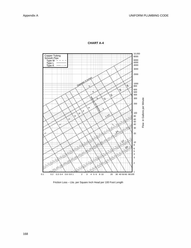
UNIFORM PLUMBING CODE
168
Appendix A
Flo
w i
n G
allo
ns p
er M
inut
e
10,0008000
1000
2000
3000
400050006000
200
300
400500600
800
100
10
20
30
405060
80
1
2
3
456
8
0.1 0.2 0.3 10.4 0.6 0.8 102 3 4 5 6 8 20 30 10040 50 60 80
Copper TubingSmooth Pipe Type M Type L Type K
Diameter 6 inches
5
4
3
2
1-1/2
1
3/4
1/2
3/8
Velocity 10 feet/sec.
40
30
20
15
8
6
5
4
3
2
1
CHART A-4
Friction Loss – Lbs. per Square Inch Head per 100 Foot Length
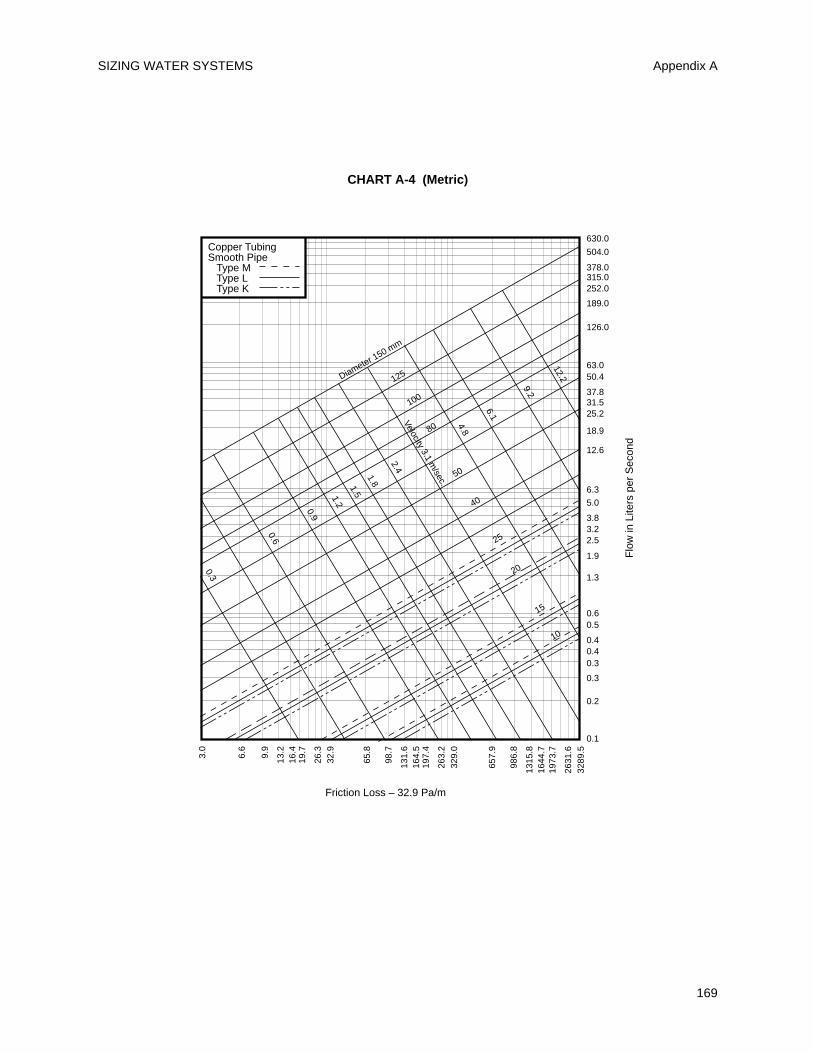
SIZING WATER SYSTEMS
169
Appendix A
Flo
w in
Lite
rs p
er S
econ
d
Copper TubingSmooth Pipe Type M Type L Type K
630.0
504.0
63.0
126.0
189.0
252.0315.0378.0
12.6
18.9
25.231.537.8
50.4
6.3
0.6
1.3
1.9
2.53.23.8
5.0
0.1
0.2
0.3
0.30.40.4
0.5
3.0
6.6
9.9
13.2
16.4
26.3
32.9
19.7
65.8
98.7
131.
616
4.5
263.
232
9.0
197.
4
657.
9
986.
8
1315
.816
44.7
2631
.632
89.5
1973
.7
Diameter 150 mm
125
100
80
50
40
25
20
15
10
Velocity 3.1 m/sec.
12.2
9.2
6.1
4.8
2.4
1.81.51.2
0.9
0.6
0.3
CHART A-4 (Metric)
Friction Loss – 32.9 Pa/m
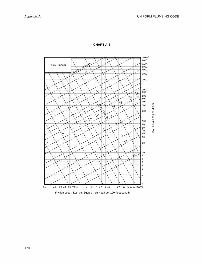
UNIFORM PLUMBING CODE
170
Appendix A
10,0008000
1000
2000
3000
400050006000
200
300
400500600
800
100
10
20
30
405060
80
1
2
3
456
8
0.1 0.2 0.3 10.4 0.6 0.8 102 3 4 5 6 8 20 30 10040 50 60 80
6
5
4
3
2
1-1/2
1
3/4
1/2
3/8
Velocity 10 feet/sec.
40
30
20
15
8
6
5
4
3
2
1
Diameter 12 inches
8
10
Fairly Smooth
Flo
w i
n G
allo
ns p
er M
inut
e
Friction Loss – Lbs. per Square Inch Head per 100 Foot Length
CHART A-5
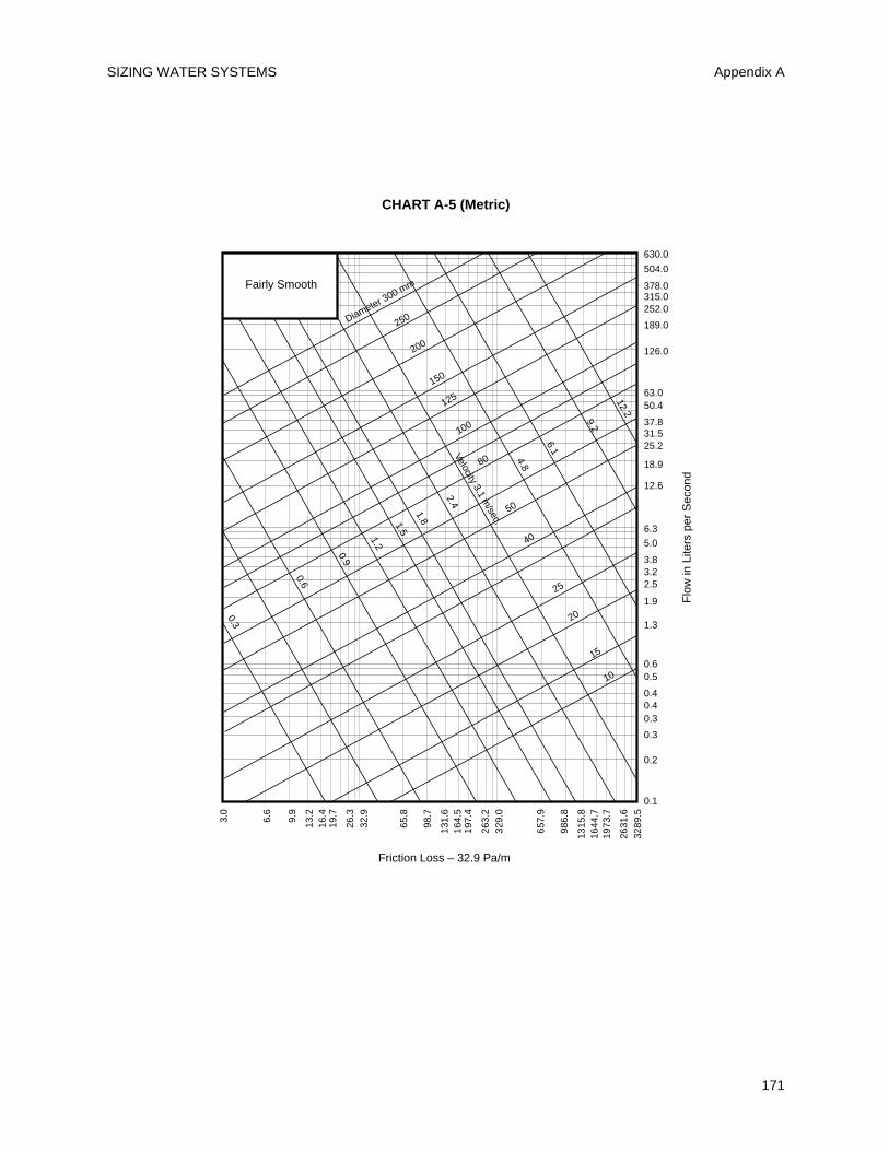
SIZING WATER SYSTEMS
171
Appendix A
Flo
w in
Lite
rs p
er S
econ
d
150
125
100
80
50
40
25
20
15
10
Velocity 3.1 m/sec.
12.2
9.2
6.1
4.8
2.4
1.81.5
1.2
0.9
0.6
0.3
Diameter 300 mm
200
250
630.0
504.0
63.0
126.0
189.0
252.0315.0378.0
12.6
18.9
25.231.537.8
50.4
6.3
0.6
1.3
1.9
2.53.23.8
5.0
0.1
0.2
0.3
0.30.40.4
0.5
3.0
6.6
9.9
13.2
16.4
26.3
32.9
19.7
65.8
98.7
131.
616
4.5
263.
232
9.0
197.
4
657.
9
986.
8
1315
.816
44.7
2631
.632
89.5
1973
.7
Fairly Smooth
Friction Loss – 32.9 Pa/m
CHART A-5 (Metric)
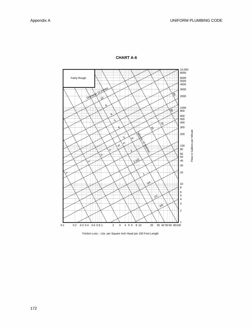
UNIFORM PLUMBING CODE
172
Appendix A
10,0008000
1000
2000
3000
400050006000
200
300
400500600
800
100
10
20
30
405060
80
1
2
3
456
8
0.1 0.2 0.3 10.4 0.6 0.8 102 3 4 5 6 8 20 30 10040 50 60 80
6
5
4
3
2
1-1/2
1
3/4
1/2
3/8
Velocity 10 feet/sec.
4030
20
15
8
6
5
4
3
2
1
Diameter 12 inches
8
10
Fairly Rough
Friction Loss – Lbs. per Square Inch Head per 100 Foot Length
Flo
w in
Gal
lons
per
Min
ute
CHART A-6
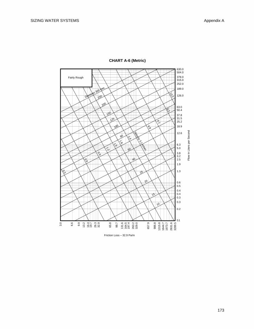
SIZING WATER SYSTEMS
173
Appendix A
150
125
100
80
50
40
25
20
15
10
Velocity 3.1 m/sec.
12.2
9.2
6.1
4.8
2.4
1.81.5
1.2
0.9
0.6
0.3
Diameter 300 mm
200
250
Fairly Rough
630.0504.0
63.0
126.0
189.0
252.0315.0378.0
12.6
18.9
25.231.537.8
50.4
6.3
0.6
1.3
1.9
2.53.23.8
5.0
0.1
0.2
0.3
0.30.40.4
0.5
3.0
6.6
9.9
26.3
13.2
16.4
19.7
329.
0
65.8
98.7
131.
616
4.5
197.
4
263.
2
657.
9
986.
8
3289
.5
1315
.816
44.7
1973
.7
2631
.6
32.9
Friction Loss – 32.9 Pa/m
Flo
w in
Lite
rs p
er S
econ
d
CHART A-6 (Metric)
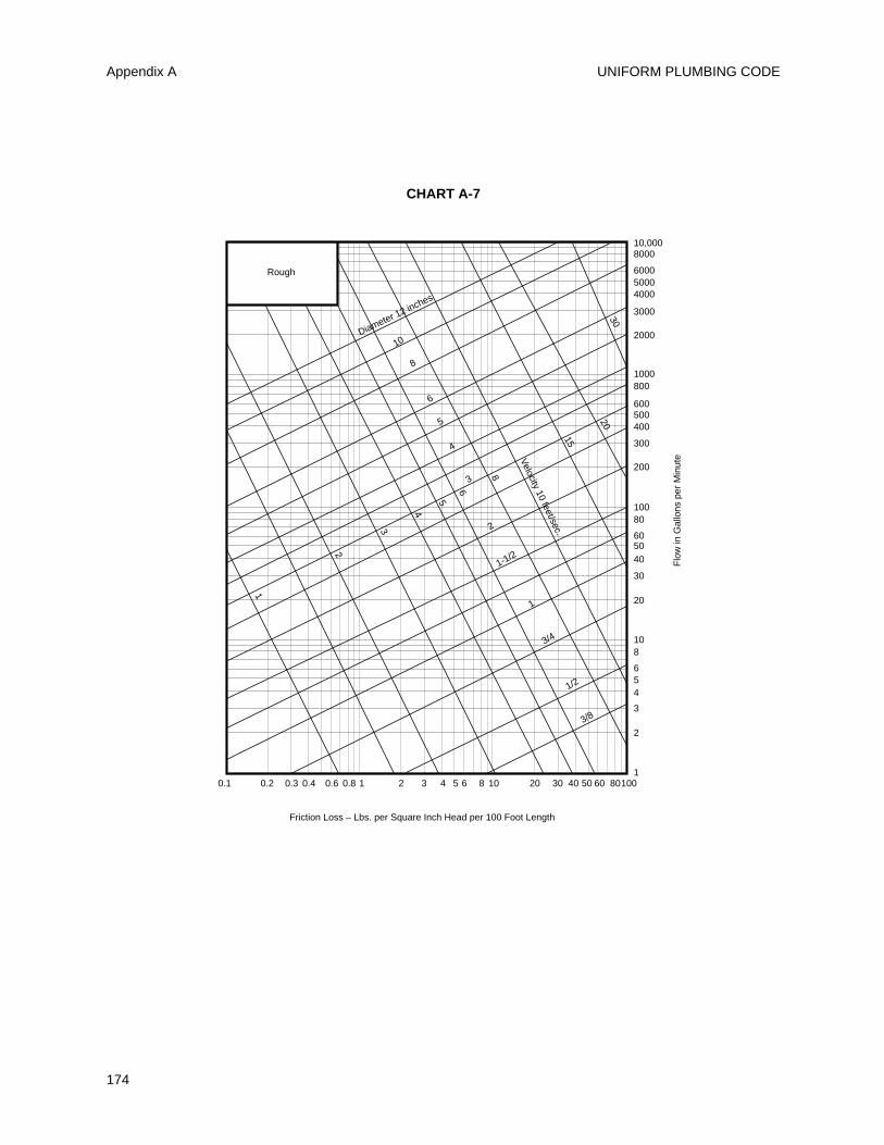
UNIFORM PLUMBING CODE
174
Appendix A
0.1 0.2 0.3 10.4 0.6 0.8 102 3 4 5 6 8 20 30 10040 50 60 80
6
5
4
3
2
1-1/2
1
3/4
1/2
3/8
Velocity 10 feet/sec.
3020
15
8
6
5
4
3
2
1
Diameter 12 inches
8
10
Rough
10,0008000
1000
2000
3000
400050006000
200
300
400500600
800
100
10
20
30
405060
80
1
2
3
456
8
Friction Loss – Lbs. per Square Inch Head per 100 Foot Length
Flo
w in
Gal
lons
per
Min
ute
CHART A-7
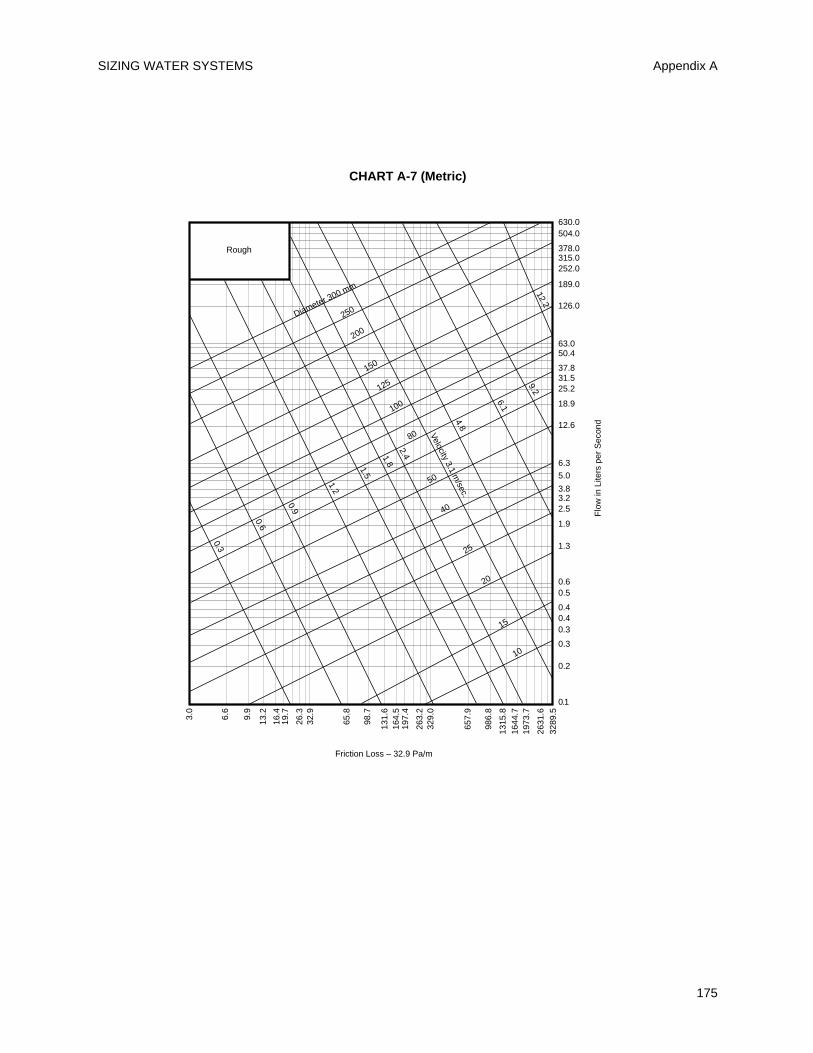
SIZING WATER SYSTEMS
175
Appendix A
Rough
Friction Loss – 32.9 Pa/m
Flo
w in
Lite
rs p
er S
econ
d
630.0504.0
63.0
126.0
189.0
252.0315.0378.0
12.6
18.9
25.231.537.8
50.4
6.3
0.6
1.3
1.9
2.53.23.8
5.0
0.1
0.2
0.3
0.30.40.4
0.5
3.0
6.6
9.9
26.3
13.2
16.4
19.7
329.
0
65.8
98.7
131.
616
4.5
197.
4
263.
2
657.
9
986.
8
3289
.5
1315
.816
44.7
1973
.7
2631
.6
32.9
150
125
100
80
50
40
25
20
15
10
Velocity 3.1 m/sec.
9.2
6.1
4.8
2.41.8
1.5
1.2
0.9
0.6
0.3
Diameter 300 mm
200
250
12.2
CHART A-7 (Metric)

UNIFORM PLUMBING CODE
176
177
B 1 Combination waste and vent systems, asoutlined in Section 910.0 of this Code, cover thehorizontal wet venting of a series of traps by meansof a common waste and vent pipe. Line sizes at leasttwo (2) pipe sizes larger than those required for aconventional system are designed to maintain awetted perimeter or flow line low enough in thewaste pipe to allow adequate air movement in theupper portion, thus balancing the system. Sinks,lavatories, and other fixtures that rough in above thefloor, should not be permitted on a combinationwaste and vent system, which, at best, is merely anexpedient designed to be used in locations where itwould be structurally impractical to provide ventingin the conventional manner.
Combination waste and vent systems areintended primarily for extensive floor or showerdrain installations where separate venting is notpractical, for floor sinks in markets, demonstration orwork tables in school buildings, or for similarapplications where the fixtures are not adjacent towalls or partitions. Due to its oversize characteristics,such a waste system is not self scouring andconsequently care should be exercised as to the typeof fixtures connected thereto, and to the location ofcleanouts. In view of its grease-producing potential,restaurant kitchen equipment should not beconnected to a combination waste and vent system.
B 2 Caution must be exercised to excludeappurtenances delivering large quantities or surgesof water (such as pumps, sand interceptors, etc.)from combination waste and vent systems in orderthat adequate venting will be maintained. Smallfixtures with a waste producing potential of less thanseven and one-half (7-1/2) gallons per minute (0.5L/sec.) may be safely assigned a loading value ofone (1) unit. Long runs should be laid at theminimum permissible slope in order to keeptailpieces as short as possible. Tailpieces should notexceed two (2) feet (610 mm) in length which maynecessitate slopes up to forty-five (45) degrees (0.79rad) (see definition of horizontal pipe) on somebranches.
B 3 It is essential that the pneumatics of such asystem be properly engineered as the air pressurewithin the line must at all times balance that ofoutside atmosphere in order to prevent either trapseal loss or air locking between traps. Long mainsshall be provided with additional relief vents located
at intervals not exceeding one hundred (100) feet(30480 mm). Each such relief vent should equal atleast one-half (1/2) of the inside cross-sectional areaof the drain pipe served.
B 4 Trap sizes are required to be equivalent to thebranches they serve (two (2) pipe sizes larger thannormal) and tailpieces between fixtures or floordrains and such traps should be reduced to normalsize.
B 5 Duplicate layout drawings of each suchproposed piping system must be presented to theAdministrative Authority, and approval obtainedbefore any installation is made. Complicated layoutsshould be checked by qualified personnel.
B 5.1 Example of Sizing
A floor drain normally required two (2) inch (50 mm)trap and waste. On a combination waste and ventsystem both trap and waste must be increased two(2) pipe sizes (through 2-1/2" and 3") (65 mm and 80mm) which would make the trap three (3) inch (76mm), (pipe sizes recognized for this purpose are 2",2-1/2", 3", 3-1/2", 4", 4-1/2", 5", 6", etc.) (50 mm, 65mm, 80 mm, 90 mm, 100 mm, 115 mm, 125 mm, 150mm, etc.). The tailpiece between the floor drain andits trap should be two (2) inches (51 mm) (or normalsize) to insure that the amount of waste waterentering the trap only partially fills the waste branch.A three (3) inch (80 mm) floor drain would thusrequire a four (4) inch (100 mm) trap, a four (4) inch(100 mm) floor drain, and five (5) inch (125 mm)trap, etc., for the reasons previously stated.
WHEN IN DOUBT, CHECK WITH YOUR LOCALADMINISTRATIVE AUTHORITY.
APPENDIX B
EXPLANATORY NOTES ON COMBINATION WASTE AND VENT SYSTEMS
(See Section 910.0 for specific limitations.)

UNIFORM PLUMBING CODE
178
NFPANFPANFPANFPANFPANFPANFPANFPANFPANFPANFPANFPANFPANFPANFPANFPANFPANFPANFPANFPANFPANFPAN
NFPANFPANFPANFPANFPANFPANFPANFPANFPANFPANFPANFPANFPANFPANFPANFPANFPANFPANFPANFPANFPAN
C 1.0 Sizing of Category I Venting Systems
C 1.1 Definitions. The following definitions apply totables in this part:
Appliance Categorized Vent Diameter/Area.The minimum vent area/diameter permissiblefor Category I appliances to maintain a nonposi-tive vent static pressure when tested in accor-dance with nationally recognized standards.
Exterior Masonry Chimneys. Masonry chimneysexposed to the outdoors on one or more sidesbelow the roof line.
Fan-Assisted Combustion System. An applianceequipped with an integral mechanical means toeither draw or force products of combustionthrough the combustion chamber or heatexchanger.
FAN Min. The minimum input rating of aCategory I, fan-assisted appliance attached to avent or connector.
FAN Max. The maximum input rating of aCategory I fan-assisted appliance attached to avent or connector.
NAT Max. The maximum input rating of aCategory I, draft hood-equipped applianceattached to a vent or connector.
FAN+FAN. The maximum combined applianceinput rating of two or more Category I fan-assist-ed appliances attached to the common vent.
FAN+NAT. The maximum combined applianceinput rating of one or more Category I fan-assist-ed appliances and one or more Category I drafthood-equipped appliances attached to the com-mon vent.
NAT+NAT. The maximum combined applianceinput rating of two or more Category I drafthood-equipped appliances attached to the com-mon vent.
NA. Vent configuration is not permitted due topotential for condensate formation or pressuriza-tion of the venting system, or not applicable dueto physical or geometric restraints.
C 2.0 Additional Requirements to Single ApplianceVent Tables C-1 through C-5.
C 2.1 These venting tables shall not be used whereobstructions, as described in the exceptions to Section7.151, are installed in the venting system. The instal-lation of vents serving listed appliances with vent
dampers shall be in accordance with the appliancemanufacturer's instructions.
C 2.2 If the vent size determined from the tables issmaller than the appliance draft hood outlet or fluecollar, the smaller size shall be permitted to be usedprovided:
(a) The total vent height (H) is at least 10 ft (3 m).
(b) Vents for appliance draft hood outlets or fluecollars 12 in. (30 cm) in diameter or smaller arenot reduced more than one table size.
(c) Vents for appliance draft hood outlets or fluecollars larger than 12 in. (30 cm) in diameter arenot reduced more than two table sizes.
(d) The maximum capacity listed in the tables fora fan-assisted appliance is reduced by 10 percent(0.90 x maximum table capacity).
(e) The draft hood outlet is greater than 4 in. (10cm) in diameter. Do not connect a 3-in. (8-cm)diameter vent to a 4-in. (10-cm) diameter drafthood outlet. This provision shall not apply to fan-assisted appliances.
C 2.3 Single-appliance venting configurations withzero (0) lateral lengths in Tables C-1, C-2, and C-5shall have no elbows in the venting system. For ventconfigurations with lateral lengths, the venting tablesinclude allowance for two 90-degree turns. For eachadditional 90-degree turn, or equivalent, the maxi-mum capacity listed in the venting tables shall bereduced by 10 percent (0.90 x maximum table capaci-ty). Two or more turns, the combined angles of whichequal 90 degrees, shall be considered equivalent toone 90-degree turn.
C 2.4 Zero (0) lateral (L) shall apply only to a straightvertical vent attached to a top outlet draft hood orflue collar.
C 2.5 Sea level input ratings shall be used whendetermining maximum capacity for high altitudeinstallation. Actual input (derated for altitude) shallbe used for determining minimum capacity for highaltitude installation.
C 2.6 For appliances with more than one input rate,the minimum vent capacity (FAN Min) determinedfrom the tables shall be less than the lowest applianceinput rating, and the maximum vent capacity (FANMax/NAT Max) determined from the tables shall begreater than the highest appliance rating input.
C 2.7 Listed corrugated metallic chimney liner sys-tems in masonry chimneys shall be sized by using
179
APPENDIX C
Sizing of Category I Venting Systems
1Section 7.15 is from the NFPA 54, 1996 Edition (see page 182).
Table C-1 or C-2 for Type B vents with the maximumcapacity reduced by 20 percent (0.80 maximum capac-ity) and the minimum capacity as shown in Table C-1or C-2. Corrugated metallic liner systems installedwith bends or offsets shall have their maximum capac-ity further reduced in accordance with C 2.3.
C 2.8 If the vertical vent has a larger diameter thanthe vent connector, the vertical vent diameter shall beused to determine the minimum vent capacity, andthe connector diameter shall be used to determine themaximum vent capacity. The flow area of the verticalvent shall not exceed seven times the flow area of thelisted appliance categorized vent area, flue collararea, or draft hood outlet area unless designated inaccordance with approved engineering methods.
C 2.9 Tables C-1, C-2, C-3, C-4 and C-5 shall be usedfor chimneys and vents not exposed to the outdoorsbelow the roof line. A Type B vent or listed chimneylining system passing through an unused masonrychimney flue shall not be considered to be exposed tothe outdoors. Table C-3 in combination with Table C-11 shall be used for clay-tile-lined exterior masonrychimneys, provided:
(a) Vent connector is Type B double-wall, and
(b) Vent connector length is limited to 1-1/2 ft foreach inch (18 cm per cm) of vent connector diam-eter, and
(c) The appliance is draft hood-equipped, and
(d) The input rating is less than the maximumcapacity given by Table C-3, and
(e) For a space-heating appliance, the input rat-ing is greater than the minimum capacity givenby Table C-11.
If these conditions cannot be met, an alterna-tive venting design shall be used, such as a listedchimney lining system.
Exception: The installation of vents serving listedappliances shall be permitted to be in accordancewith the appliance manufacturer's instructionsand the terms of the listing.
C 2.10 Vent connectors shall not be upsized morethan two sizes greater than the listed appliance cate-gorized vent diameter, flue collar diameter, or drafthood outlet diameter.
C 2.11 In a single run of vent or vent connector, morethan one diameter and type shall be permitted to beused, provided that all the sizes and types are per-mitted by the tables.
C 2.12 Interpolation shall be permitted in calculatingcapacities for vent dimensions that fall between tableentries.
C 2.13 Extrapolation beyond the table entries shallnot be permitted.
For SI units: 1 in. = 2.54 cm; 1 ft = 0.305 m; 1000Btu per hr = 0.293 kW; 1 in.2 = 6.45 cm2.
C 3.0 Additional Requirements to MultipleAppliance Vent Tables C-6 through C-13.
C 3.1 These venting tables shall not be used whereobstructions, are installed in the venting system. Theinstallation of vents serving listed appliances withvent dampers shall be in accordance with the appli-ance manufacturer's instructions.
C 3.2 The maximum vent connector horizontallength shall be 1-1/2 ft (18 in.) for each inch (18 cmper cm) of connector diameter as follows:
Connector Diameter Horizontal LengthMaximum Connector
(in.) (ft)3 44 6 5 7-1/2 6 9 7 10-1/2 8 12 9 13-1/2 10 15 12 18 14 21 16 24 18 27 20 30 22 33 24 36
For SI units: 1 inch = 2.54 cm; 1 foot = 0.305 m.
C 3.3 The vent connector shall be routed to the ventutilizing the shortest possible route. Connectors withlonger horizontal lengths than those listed above arepermitted under the following conditions:
(a) The maximum capacity (FAN Max or NATMax) of the vent connector shall be reduced 10percent for each additional multiple of the lengthlisted above. For example, the maximum lengthlisted above for a 4-in. (10-cm) connector is 6 ft(1.8 m). With a connector length greater than 6 ft(1.8 m) but not exceeding 12 ft (3.7 m), the maxi-mum capacity must be reduced by 10 percent(0.90 x maximum vent connector capacity). Witha connector length greater than 12 ft (3.7 m) butnot exceeding 18 ft (5.5 m), the maximum capac-ity must be reduced by 20 percent (0.80 x maxi-mum vent capacity).
(b) For a connector serving a fan-assisted appli-ance, the minimum capacity (FAN Min) of the
UNIFORM PLUMBING CODE
180
Appendix C
NFPANFPANFPANFPANFPANFPANFPANFPANFPANFPANFPANFPANFPANFPANFPANFPANFPANFPANFPANFPANFPANFPANFPA
NFPANFPANFPANFPANFPANFPANFPANFPANFPANFPANFPANFPANFPANFPANFPANFPANFPANFPANFPANFPANFPANFPANFPA
connector shall be determined by referring to thecorresponding single appliance table. For Type Bdouble-wall connectors, Table C-1 shall be used.For single-wall connectors, Table C-2 shall beused. The height (H) and lateral (L) shall bemeasured according to the procedures for a sin-gle appliance vent, as if the other appliances werenot present.
C 3.4 If the vent connectors are combined prior toentering the common vent, the maximum commonvent capacity listed in the common venting tablesshall be reduced by 10 percent (0.90 x maximum com-mon vent capacity). The length of the common ventconnector manifold (LM) shall not exceed 1-1/2 ft (18in.) for each inch (18 cm per cm) of common vent con-nector manifold diameter (D).
C 3.5 If the common vertical vent is offset, the maxi-mum common vent capacity listed in the commonventing tables shall be reduced by 20 percent (0.80 xmaximum common vent capacity), the equivalent oftwo 90-degree turns. The horizontal length of the com-mon vent offset (LM) shall not exceed 1-1/2 ft for eachinch (18 cm per cm) of common vent diameter (D).
C 3.6 Excluding elbows counted in C 3.6, for eachadditional 90-degree turn in excess of two, the maxi-mum capacity of that portion of the venting systemshall be reduced by 10 percent (0.90 x maximum com-mon vent capacity). Two or more turns, the combinedangles of which equal 90 degrees, shall be consideredequivalent to one 90-degree turn.
C 3.7 The cross-sectional area of the common ventshall be equal to or greater than the cross-sectionalarea of the largest connector.
C 3.8 Interconnection fittings shall be the same sizeas the common vent.
C 3.9 Sea level input ratings shall be used whendetermining maximum capacity for high altitudeinstallation. Actual input (derated for altitude) shallbe used for determining minimum capacity for highaltitude installation.
C 3.10 Connector rise (R) for each appliance connec-tor shall be measured from the draft hood outlet orflue collar to the centerline where the vent gasstreams come together.
C 3.11 For multiple units of gas utilization equipmentall located on one floor, available total height (H) shallbe measured from the highest draft hood outlet or fluecollar up to the level of the outlet of the common vent.
C 3.12 For multistory installations, available totalheight (H) for each segment of the system shall be thevertical distance between the highest draft hood out-let or flue collar entering that segment and the cen-terline of the next higher interconnection tee.
C 3.13 The size of the lowest connector and of thevertical vent leading to the lowest interconnection ofa multistory system shall be in accordance with TableC-1 or C-2 for available total height (H) up to the low-est interconnection.
C 3.14 Where used in multistory systems, verticalcommon vents shall be Type B double-wall and shallbe installed with a listed vent cap. A multistory com-mon vertical vent shall be permitted to have a singleoffset, provided:
(a) The offset angle does not exceed 45 degrees,and
(b) The horizontal length of the offset does notexceed 1-1/2 ft for each inch (18 cm per cm) ofcommon vent diameter of the segment in whichthe offset is located, and
(c) For the segment of the common vertical ventcontaining the offset, the common vent capacitylisted in the common venting tables is reduced by20 percent (0.80 x maximum common vent capac-ity), and
(d) A multistory common vent shall not bereduced in size above the offset.
C 3.15 Where two or more appliances are connectedto a vertical vent or chimney, the flow area of thelargest section of vertical vent or chimney shall notexceed seven times the smallest listed appliance cate-gorized vent areas, flue collar area, or draft hood out-let area unless designed in accordance with approvedengineering methods.
C 3.16 For appliances with more than one input rate,the minimum vent connector capacity (FAN Min)determined from the tables shall be less than the low-est appliance input rating, and the maximum ventconnector capacity (FAN Max or NAT Max) deter-mined from the tables shall be greater than the high-est appliance input rating.
C 3.17 Listed, corrugated metallic chimney liner sys-tems in masonry chimneys shall be sized by usingTable C-6 or C-7 for Type B vents, with the maximumcapacity reduced by 20 percent (0.80 x maximumcapacity) and the minimum capacity as shown in TableC-6 or C-7. Corrugated metallic liner systems installedwith bends or offsets shall have their maximum capac-ity further reduced in accordance with C 3.6.
C 3.18 Tables C-6, C-7, C-8, C-9, and C-10 shall beused for chimneys and vents not exposed to the out-doors below the roof line. A Type B vent or listedchimney lining system passing through an unusedmasonry chimney flue shall not be considered to beexposed to the outdoors. Tables C-12 and C-13 shallbe used for clay-tile-lined exterior masonry chim-neys, provided:
SIZING OF CATEGORY I VENTING SYSTEMS Appendix C
181
NFPANFPANFPANFPANFPANFPANFPANFPANFPANFPANFPANFPANFPANFPANFPANFPANFPANFPANFPANFPANFPANFPANFPA
NFPANFPANFPANFPANFPANFPANFPANFPANFPANFPANFPANFPANFPANFPANFPANFPANFPANFPANFPANFPANFPANFPANFPA
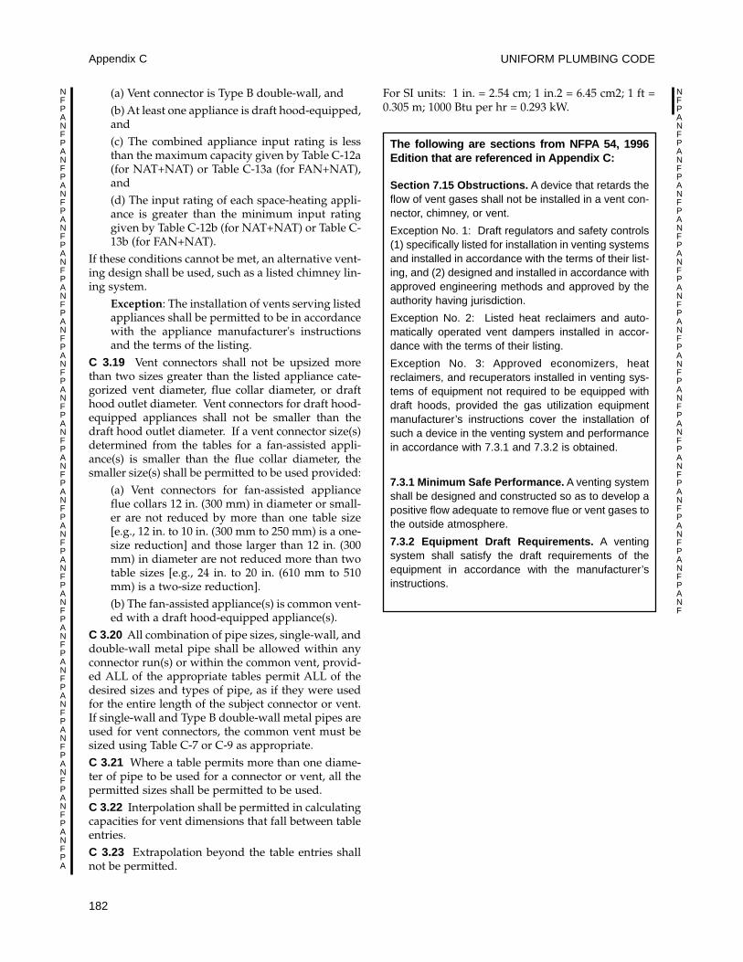
(a) Vent connector is Type B double-wall, and(b) At least one appliance is draft hood-equipped,and(c) The combined appliance input rating is lessthan the maximum capacity given by Table C-12a(for NAT+NAT) or Table C-13a (for FAN+NAT),and(d) The input rating of each space-heating appli-ance is greater than the minimum input ratinggiven by Table C-12b (for NAT+NAT) or Table C-13b (for FAN+NAT).
If these conditions cannot be met, an alternative vent-ing design shall be used, such as a listed chimney lin-ing system.
Exception: The installation of vents serving listedappliances shall be permitted to be in accordancewith the appliance manufacturer's instructionsand the terms of the listing.
C 3.19 Vent connectors shall not be upsized morethan two sizes greater than the listed appliance cate-gorized vent diameter, flue collar diameter, or drafthood outlet diameter. Vent connectors for draft hood-equipped appliances shall not be smaller than thedraft hood outlet diameter. If a vent connector size(s)determined from the tables for a fan-assisted appli-ance(s) is smaller than the flue collar diameter, thesmaller size(s) shall be permitted to be used provided:
(a) Vent connectors for fan-assisted applianceflue collars 12 in. (300 mm) in diameter or small-er are not reduced by more than one table size[e.g., 12 in. to 10 in. (300 mm to 250 mm) is a one-size reduction] and those larger than 12 in. (300mm) in diameter are not reduced more than twotable sizes [e.g., 24 in. to 20 in. (610 mm to 510mm) is a two-size reduction].(b) The fan-assisted appliance(s) is common vent-ed with a draft hood-equipped appliance(s).
C 3.20 All combination of pipe sizes, single-wall, anddouble-wall metal pipe shall be allowed within anyconnector run(s) or within the common vent, provid-ed ALL of the appropriate tables permit ALL of thedesired sizes and types of pipe, as if they were usedfor the entire length of the subject connector or vent.If single-wall and Type B double-wall metal pipes areused for vent connectors, the common vent must besized using Table C-7 or C-9 as appropriate.C 3.21 Where a table permits more than one diame-ter of pipe to be used for a connector or vent, all thepermitted sizes shall be permitted to be used.C 3.22 Interpolation shall be permitted in calculatingcapacities for vent dimensions that fall between tableentries. C 3.23 Extrapolation beyond the table entries shallnot be permitted.
For SI units: 1 in. = 2.54 cm; 1 in.2 = 6.45 cm2; 1 ft =0.305 m; 1000 Btu per hr = 0.293 kW.
UNIFORM PLUMBING CODE
182
Appendix C
NFPANFPANFPANFPANFPANFPANFPANFPANFPANFPANFPANFPANFPANFPANFPANFPANFPANFPANFPANFPANFPANFPANFPA
NFPANFPANFPANFPANFPANFPANFPANFPANFPANFPANFPANFPANFPANFPANFPANF
The following are sections from NFPA 54, 1996Edition that are referenced in Appendix C:
Section 7.15 Obstructions. A device that retards theflow of vent gases shall not be installed in a vent con-nector, chimney, or vent.
Exception No. 1: Draft regulators and safety controls(1) specifically listed for installation in venting systemsand installed in accordance with the terms of their list-ing, and (2) designed and installed in accordance withapproved engineering methods and approved by theauthority having jurisdiction.
Exception No. 2: Listed heat reclaimers and auto-matically operated vent dampers installed in accor-dance with the terms of their listing.
Exception No. 3: Approved economizers, heatreclaimers, and recuperators installed in venting sys-tems of equipment not required to be equipped withdraft hoods, provided the gas utilization equipmentmanufacturer’s instructions cover the installation ofsuch a device in the venting system and performancein accordance with 7.3.1 and 7.3.2 is obtained.
7.3.1 Minimum Safe Performance. A venting systemshall be designed and constructed so as to develop apositive flow adequate to remove flue or vent gases tothe outside atmosphere.
7.3.2 Equipment Draft Requirements. A ventingsystem shall satisfy the draft requirements of theequipment in accordance with the manufacturer’sinstructions.
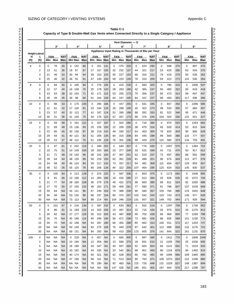
SIZING OF CATEGORY I VENTING SYSTEMS Appendix C
183
NFPANFPANFPANFPANFPANFPANFPANFPANFPANFPANFPANFPANFPANFPANFPANFPANFPANFPANFPANFPANFPANFPANFPA
NFPANFPANFPANFPANFPANFPANFPANFPANFPANFPANFPANFPANFPANFPANFPANFPANFPANFPANFPANFPANFPANFPANFPA
Table C-1 Capacity of Type B Double-Wall Gas Vents when Connected Directly to a Single Category I Appliance
Vent Diameter — D
3" 4" 5" 6" 7" 8" 9"
Appliance Input Rating in Thousands of Btu per HourHeight Lateral
H L FAN NAT FAN NAT FAN NAT FAN NAT FAN NAT FAN NAT FAN NAT(ft) (ft) Min Max Max Min Max Max Min Max Max Min Max Max Min Max Max Min Max Max Min Max Max
6 0 0 78 46 0 152 86 0 251 141 0 375 205 0 524 285 0 698 370 0 897 470
2 13 51 36 18 97 67 27 157 105 32 232 157 44 321 217 53 425 285 63 543 370
4 21 49 34 30 94 64 39 153 103 50 227 153 66 316 211 79 419 279 93 536 362
6 25 46 32 36 91 61 47 149 100 59 223 149 78 310 205 93 413 273 110 530 354
8 0 0 84 50 0 165 94 0 276 155 0 415 235 0 583 320 0 780 415 0 1006 537
2 12 57 40 16 109 75 25 178 120 28 263 180 42 365 247 50 483 322 60 619 418
5 23 53 38 32 103 71 42 171 115 53 255 173 70 356 237 83 473 313 99 607 407
8 28 49 35 39 98 66 51 164 109 64 247 165 84 347 227 99 463 303 117 596 396
10 0 0 88 53 0 175 100 0 295 166 0 447 255 0 631 345 0 847 450 0 1096 585
2 12 61 42 17 118 81 23 194 129 26 289 195 40 402 273 48 533 355 57 684 457
5 23 57 40 32 113 77 41 187 124 52 280 188 68 392 263 81 522 346 95 671 446
10 30 51 36 41 104 70 54 176 115 67 267 175 88 376 245 104 504 330 122 651 427
15 0 0 94 58 0 191 112 0 327 187 0 502 285 0 716 390 0 970 525 0 1263 682
2 11 69 48 15 136 93 20 226 150 22 339 225 38 475 316 45 633 414 53 815 544
5 22 65 45 30 130 87 39 219 142 49 330 217 64 463 300 76 620 403 90 800 529
10 29 59 41 40 121 82 51 206 135 64 315 208 84 445 288 99 600 386 116 777 507
15 35 53 37 48 112 76 61 195 128 76 301 198 98 429 275 115 580 373 134 755 491
20 0 0 97 61 0 202 119 0 349 202 0 540 307 0 776 430 0 1057 575 0 1384 752
2 10 75 51 14 149 100 18 250 166 20 377 249 33 531 346 41 711 470 50 917 612
5 21 71 48 29 143 96 38 242 160 47 367 241 62 519 337 73 697 460 86 902 599
10 28 64 44 38 133 89 50 229 150 62 351 228 81 499 321 95 675 443 112 877 576
15 34 58 40 46 124 84 59 217 142 73 337 217 94 481 308 111 654 427 129 853 557
20 48 52 35 55 116 78 69 206 134 84 322 206 107 464 295 125 634 410 145 830 537
30 0 0 100 64 0 213 128 0 374 220 0 587 336 0 853 475 0 1173 650 0 1548 855
2 9 81 56 13 166 112 14 283 185 18 432 280 27 613 394 33 826 535 42 1072 700
5 21 77 54 28 160 108 36 275 176 45 421 273 58 600 385 69 811 524 82 1055 688
10 27 70 50 37 150 102 48 262 171 59 405 261 77 580 371 91 788 507 107 1028 668
15 33 64 NA 44 141 96 57 249 163 70 389 249 90 560 357 105 765 490 124 1002 648
20 56 58 NA 53 132 90 66 237 154 80 374 237 102 542 343 119 743 473 139 977 628
30 NA NA NA 73 113 NA 88 214 NA 104 346 219 131 507 321 149 702 444 171 929 594
50 0 0 101 67 0 216 134 0 397 232 0 633 363 0 932 518 0 1297 708 0 1730 952
2 8 86 61 11 183 122 14 320 206 15 497 314 22 715 445 26 975 615 33 1276 813
5 20 82 NA 27 177 119 35 312 200 43 487 308 55 702 438 65 960 605 77 1259 798
10 26 76 NA 35 168 114 45 299 190 56 471 298 73 681 426 86 935 589 101 1230 773
15 59 70 NA 42 158 NA 54 287 180 66 455 288 85 662 413 100 911 572 117 1203 747
20 NA NA NA 50 149 NA 63 275 169 76 440 278 97 642 401 113 888 556 131 1176 722
30 NA NA NA 69 131 NA 84 250 NA 99 410 259 123 605 376 141 844 522 161 1125 670
100 0 NA NA NA 0 218 NA 0 407 NA 0 665 400 0 997 560 0 1411 770 0 1908 1040
2 NA NA NA 10 194 NA 12 354 NA 13 566 375 18 831 510 21 1155 700 25 1536 935
5 NA NA NA 26 189 NA 33 347 NA 40 557 369 52 820 504 60 1141 692 71 1519 926
10 NA NA NA 33 182 NA 43 335 NA 53 542 361 68 801 493 80 1118 679 94 1492 910
15 NA NA NA 40 174 NA 50 321 NA 62 528 353 80 782 482 93 1095 666 109 1465 895
20 NA NA NA 47 166 NA 59 311 NA 71 513 344 90 763 471 105 1073 653 122 1438 880
30 NA NA NA NA NA NA 78 290 NA 92 483 NA 115 726 449 131 1029 627 149 1387 849
50 NA NA NA NA NA NA NA NA NA 147 428 NA 180 651 405 197 944 575 217 1288 787
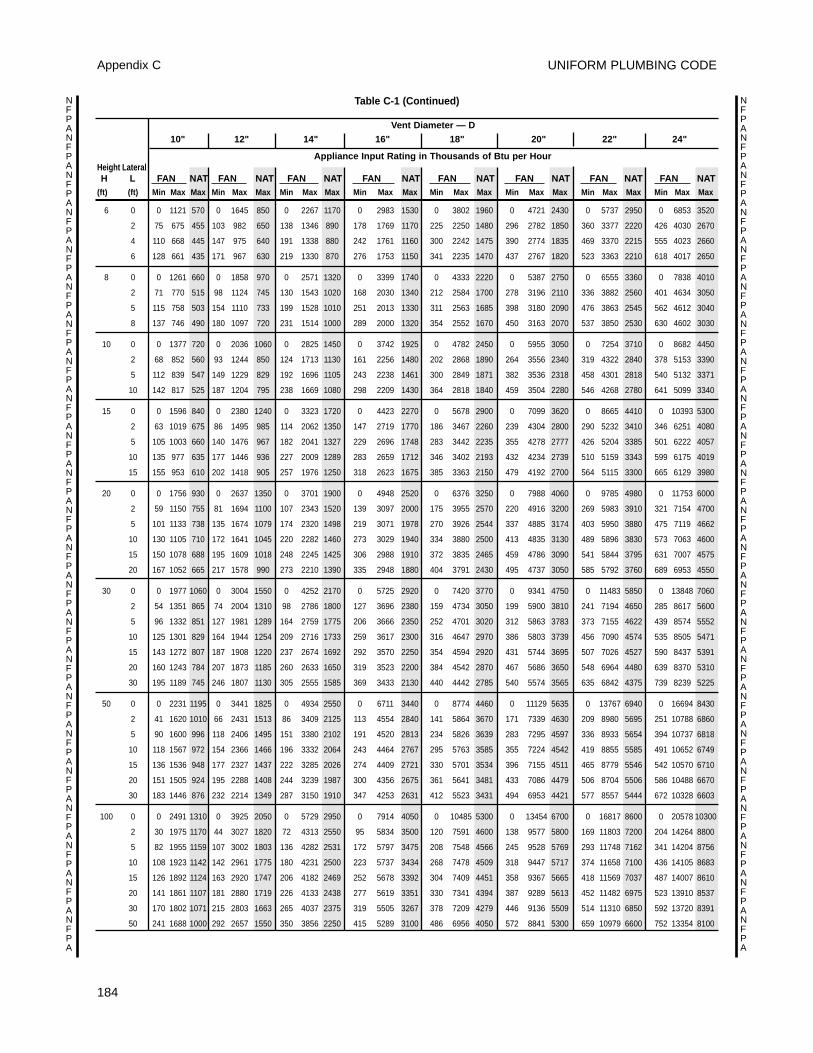
UNIFORM PLUMBING CODE
184
Appendix C
NFPANFPANFPANFPANFPANFPANFPANFPANFPANFPANFPANFPANFPANFPANFPANFPANFPANFPANFPANFPANFPANFPANFPA
NFPANFPANFPANFPANFPANFPANFPANFPANFPANFPANFPANFPANFPANFPANFPANFPANFPANFPANFPANFPANFPANFPANFPA
Table C-1 (Continued)
Vent Diameter — D
10" 12" 14" 16" 18" 20" 22" 24"
Appliance Input Rating in Thousands of Btu per HourHeight LateralH L FAN NAT FAN NAT FAN NAT FAN NAT FAN NAT FAN NAT FAN NAT FAN NAT
(ft) (ft) Min Max Max Min Max Max Min Max Max Min Max Max Min Max Max Min Max Max Min Max Max Min Max Max
6 0 0 1121 570 0 1645 850 0 2267 1170 0 2983 1530 0 3802 1960 0 4721 2430 0 5737 2950 0 6853 3520
2 75 675 455 103 982 650 138 1346 890 178 1769 1170 225 2250 1480 296 2782 1850 360 3377 2220 426 4030 2670
4 110 668 445 147 975 640 191 1338 880 242 1761 1160 300 2242 1475 390 2774 1835 469 3370 2215 555 4023 2660
6 128 661 435 171 967 630 219 1330 870 276 1753 1150 341 2235 1470 437 2767 1820 523 3363 2210 618 4017 2650
8 0 0 1261 660 0 1858 970 0 2571 1320 0 3399 1740 0 4333 2220 0 5387 2750 0 6555 3360 0 7838 4010
2 71 770 515 98 1124 745 130 1543 1020 168 2030 1340 212 2584 1700 278 3196 2110 336 3882 2560 401 4634 3050
5 115 758 503 154 1110 733 199 1528 1010 251 2013 1330 311 2563 1685 398 3180 2090 476 3863 2545 562 4612 3040
8 137 746 490 180 1097 720 231 1514 1000 289 2000 1320 354 2552 1670 450 3163 2070 537 3850 2530 630 4602 3030
10 0 0 1377 720 0 2036 1060 0 2825 1450 0 3742 1925 0 4782 2450 0 5955 3050 0 7254 3710 0 8682 4450
2 68 852 560 93 1244 850 124 1713 1130 161 2256 1480 202 2868 1890 264 3556 2340 319 4322 2840 378 5153 3390
5 112 839 547 149 1229 829 192 1696 1105 243 2238 1461 300 2849 1871 382 3536 2318 458 4301 2818 540 5132 3371
10 142 817 525 187 1204 795 238 1669 1080 298 2209 1430 364 2818 1840 459 3504 2280 546 4268 2780 641 5099 3340
15 0 0 1596 840 0 2380 1240 0 3323 1720 0 4423 2270 0 5678 2900 0 7099 3620 0 8665 4410 0 10393 5300
2 63 1019 675 86 1495 985 114 2062 1350 147 2719 1770 186 3467 2260 239 4304 2800 290 5232 3410 346 6251 4080
5 105 1003 660 140 1476 967 182 2041 1327 229 2696 1748 283 3442 2235 355 4278 2777 426 5204 3385 501 6222 4057
10 135 977 635 177 1446 936 227 2009 1289 283 2659 1712 346 3402 2193 432 4234 2739 510 5159 3343 599 6175 4019
15 155 953 610 202 1418 905 257 1976 1250 318 2623 1675 385 3363 2150 479 4192 2700 564 5115 3300 665 6129 3980
20 0 0 1756 930 0 2637 1350 0 3701 1900 0 4948 2520 0 6376 3250 0 7988 4060 0 9785 4980 0 11753 6000
2 59 1150 755 81 1694 1100 107 2343 1520 139 3097 2000 175 3955 2570 220 4916 3200 269 5983 3910 321 7154 4700
5 101 1133 738 135 1674 1079 174 2320 1498 219 3071 1978 270 3926 2544 337 4885 3174 403 5950 3880 475 7119 4662
10 130 1105 710 172 1641 1045 220 2282 1460 273 3029 1940 334 3880 2500 413 4835 3130 489 5896 3830 573 7063 4600
15 150 1078 688 195 1609 1018 248 2245 1425 306 2988 1910 372 3835 2465 459 4786 3090 541 5844 3795 631 7007 4575
20 167 1052 665 217 1578 990 273 2210 1390 335 2948 1880 404 3791 2430 495 4737 3050 585 5792 3760 689 6953 4550
30 0 0 1977 1060 0 3004 1550 0 4252 2170 0 5725 2920 0 7420 3770 0 9341 4750 0 11483 5850 0 13848 7060
2 54 1351 865 74 2004 1310 98 2786 1800 127 3696 2380 159 4734 3050 199 5900 3810 241 7194 4650 285 8617 5600
5 96 1332 851 127 1981 1289 164 2759 1775 206 3666 2350 252 4701 3020 312 5863 3783 373 7155 4622 439 8574 5552
10 125 1301 829 164 1944 1254 209 2716 1733 259 3617 2300 316 4647 2970 386 5803 3739 456 7090 4574 535 8505 5471
15 143 1272 807 187 1908 1220 237 2674 1692 292 3570 2250 354 4594 2920 431 5744 3695 507 7026 4527 590 8437 5391
20 160 1243 784 207 1873 1185 260 2633 1650 319 3523 2200 384 4542 2870 467 5686 3650 548 6964 4480 639 8370 5310
30 195 1189 745 246 1807 1130 305 2555 1585 369 3433 2130 440 4442 2785 540 5574 3565 635 6842 4375 739 8239 5225
50 0 0 2231 1195 0 3441 1825 0 4934 2550 0 6711 3440 0 8774 4460 0 11129 5635 0 13767 6940 0 16694 8430
2 41 1620 1010 66 2431 1513 86 3409 2125 113 4554 2840 141 5864 3670 171 7339 4630 209 8980 5695 251 10788 6860
5 90 1600 996 118 2406 1495 151 3380 2102 191 4520 2813 234 5826 3639 283 7295 4597 336 8933 5654 394 10737 6818
10 118 1567 972 154 2366 1466 196 3332 2064 243 4464 2767 295 5763 3585 355 7224 4542 419 8855 5585 491 10652 6749
15 136 1536 948 177 2327 1437 222 3285 2026 274 4409 2721 330 5701 3534 396 7155 4511 465 8779 5546 542 10570 6710
20 151 1505 924 195 2288 1408 244 3239 1987 300 4356 2675 361 5641 3481 433 7086 4479 506 8704 5506 586 10488 6670
30 183 1446 876 232 2214 1349 287 3150 1910 347 4253 2631 412 5523 3431 494 6953 4421 577 8557 5444 672 10328 6603
100 0 0 2491 1310 0 3925 2050 0 5729 2950 0 7914 4050 0 10485 5300 0 13454 6700 0 16817 8600 0 20578 10300
2 30 1975 1170 44 3027 1820 72 4313 2550 95 5834 3500 120 7591 4600 138 9577 5800 169 11803 7200 204 14264 8800
5 82 1955 1159 107 3002 1803 136 4282 2531 172 5797 3475 208 7548 4566 245 9528 5769 293 11748 7162 341 14204 8756
10 108 1923 1142 142 2961 1775 180 4231 2500 223 5737 3434 268 7478 4509 318 9447 5717 374 11658 7100 436 14105 8683
15 126 1892 1124 163 2920 1747 206 4182 2469 252 5678 3392 304 7409 4451 358 9367 5665 418 11569 7037 487 14007 8610
20 141 1861 1107 181 2880 1719 226 4133 2438 277 5619 3351 330 7341 4394 387 9289 5613 452 11482 6975 523 13910 8537
30 170 1802 1071 215 2803 1663 265 4037 2375 319 5505 3267 378 7209 4279 446 9136 5509 514 11310 6850 592 13720 8391
50 241 1688 1000 292 2657 1550 350 3856 2250 415 5289 3100 486 6956 4050 572 8841 5300 659 10979 6600 752 13354 8100
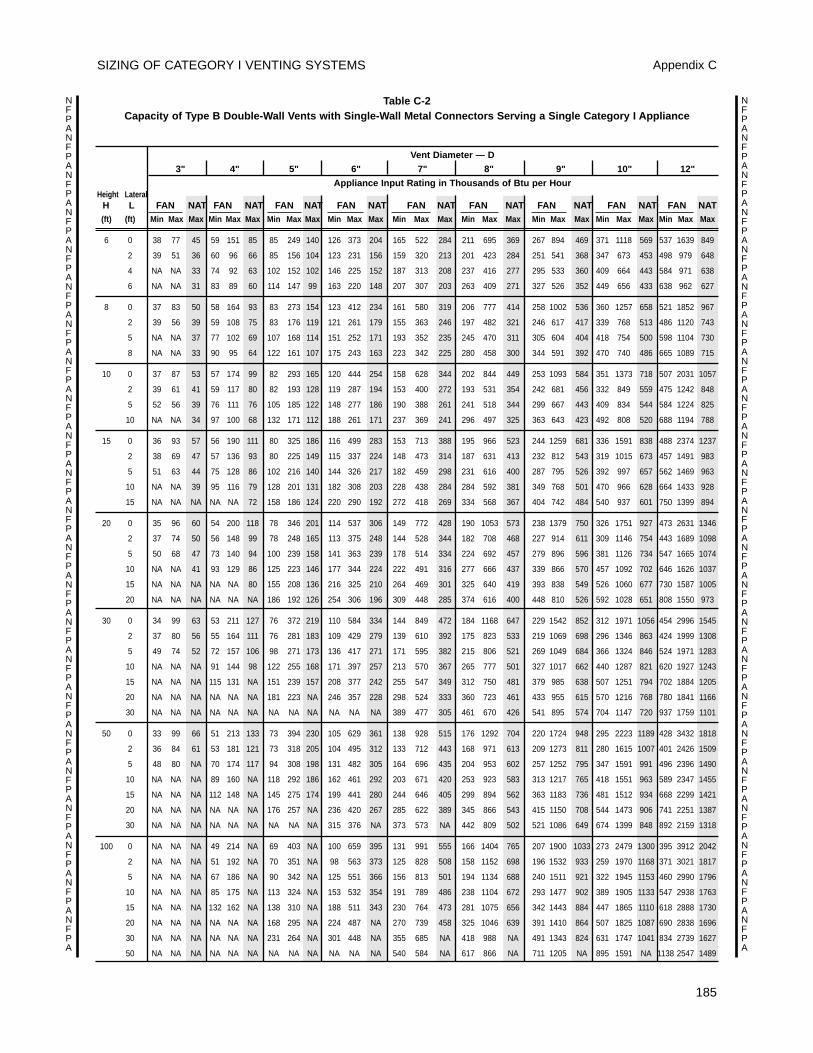
SIZING OF CATEGORY I VENTING SYSTEMS Appendix C
185
NFPANFPANFPANFPANFPANFPANFPANFPANFPANFPANFPANFPANFPANFPANFPANFPANFPANFPANFPANFPANFPANFPANFPA
NFPANFPANFPANFPANFPANFPANFPANFPANFPANFPANFPANFPANFPANFPANFPANFPANFPANFPANFPANFPANFPANFPANFPA
Table C-2 Capacity of Type B Double-Wall Vents with Single-Wall Metal Connectors Serving a Single Category I Appliance
Vent Diameter — D
3" 4" 5" 6" 7" 8" 9" 10" 12"
Appliance Input Rating in Thousands of Btu per HourHeight Lateral
H L FAN NAT FAN NAT FAN NAT FAN NAT FAN NAT FAN NAT FAN NAT FAN NAT FAN NAT(ft) (ft) Min Max Max Min Max Max Min Max Max Min Max Max Min Max Max Min Max Max Min Max Max Min Max Max Min Max Max
6 0 38 77 45 59 151 85 85 249 140 126 373 204 165 522 284 211 695 369 267 894 469 371 1118 569 537 1639 849
2 39 51 36 60 96 66 85 156 104 123 231 156 159 320 213 201 423 284 251 541 368 347 673 453 498 979 648
4 NA NA 33 74 92 63 102 152 102 146 225 152 187 313 208 237 416 277 295 533 360 409 664 443 584 971 638
6 NA NA 31 83 89 60 114 147 99 163 220 148 207 307 203 263 409 271 327 526 352 449 656 433 638 962 627
8 0 37 83 50 58 164 93 83 273 154 123 412 234 161 580 319 206 777 414 258 1002 536 360 1257 658 521 1852 967
2 39 56 39 59 108 75 83 176 119 121 261 179 155 363 246 197 482 321 246 617 417 339 768 513 486 1120 743
5 NA NA 37 77 102 69 107 168 114 151 252 171 193 352 235 245 470 311 305 604 404 418 754 500 598 1104 730
8 NA NA 33 90 95 64 122 161 107 175 243 163 223 342 225 280 458 300 344 591 392 470 740 486 665 1089 715
10 0 37 87 53 57 174 99 82 293 165 120 444 254 158 628 344 202 844 449 253 1093 584 351 1373 718 507 2031 1057
2 39 61 41 59 117 80 82 193 128 119 287 194 153 400 272 193 531 354 242 681 456 332 849 559 475 1242 848
5 52 56 39 76 111 76 105 185 122 148 277 186 190 388 261 241 518 344 299 667 443 409 834 544 584 1224 825
10 NA NA 34 97 100 68 132 171 112 188 261 171 237 369 241 296 497 325 363 643 423 492 808 520 688 1194 788
15 0 36 93 57 56 190 111 80 325 186 116 499 283 153 713 388 195 966 523 244 1259 681 336 1591 838 488 2374 1237
2 38 69 47 57 136 93 80 225 149 115 337 224 148 473 314 187 631 413 232 812 543 319 1015 673 457 1491 983
5 51 63 44 75 128 86 102 216 140 144 326 217 182 459 298 231 616 400 287 795 526 392 997 657 562 1469 963
10 NA NA 39 95 116 79 128 201 131 182 308 203 228 438 284 284 592 381 349 768 501 470 966 628 664 1433 928
15 NA NA NA NA NA 72 158 186 124 220 290 192 272 418 269 334 568 367 404 742 484 540 937 601 750 1399 894
20 0 35 96 60 54 200 118 78 346 201 114 537 306 149 772 428 190 1053 573 238 1379 750 326 1751 927 473 2631 1346
2 37 74 50 56 148 99 78 248 165 113 375 248 144 528 344 182 708 468 227 914 611 309 1146 754 443 1689 1098
5 50 68 47 73 140 94 100 239 158 141 363 239 178 514 334 224 692 457 279 896 596 381 1126 734 547 1665 1074
10 NA NA 41 93 129 86 125 223 146 177 344 224 222 491 316 277 666 437 339 866 570 457 1092 702 646 1626 1037
15 NA NA NA NA NA 80 155 208 136 216 325 210 264 469 301 325 640 419 393 838 549 526 1060 677 730 1587 1005
20 NA NA NA NA NA NA 186 192 126 254 306 196 309 448 285 374 616 400 448 810 526 592 1028 651 808 1550 973
30 0 34 99 63 53 211 127 76 372 219 110 584 334 144 849 472 184 1168 647 229 1542 852 312 1971 1056 454 2996 1545
2 37 80 56 55 164 111 76 281 183 109 429 279 139 610 392 175 823 533 219 1069 698 296 1346 863 424 1999 1308
5 49 74 52 72 157 106 98 271 173 136 417 271 171 595 382 215 806 521 269 1049 684 366 1324 846 524 1971 1283
10 NA NA NA 91 144 98 122 255 168 171 397 257 213 570 367 265 777 501 327 1017 662 440 1287 821 620 1927 1243
15 NA NA NA 115 131 NA 151 239 157 208 377 242 255 547 349 312 750 481 379 985 638 507 1251 794 702 1884 1205
20 NA NA NA NA NA NA 181 223 NA 246 357 228 298 524 333 360 723 461 433 955 615 570 1216 768 780 1841 1166
30 NA NA NA NA NA NA NA NA NA NA NA NA 389 477 305 461 670 426 541 895 574 704 1147 720 937 1759 1101
50 0 33 99 66 51 213 133 73 394 230 105 629 361 138 928 515 176 1292 704 220 1724 948 295 2223 1189 428 3432 1818
2 36 84 61 53 181 121 73 318 205 104 495 312 133 712 443 168 971 613 209 1273 811 280 1615 1007 401 2426 1509
5 48 80 NA 70 174 117 94 308 198 131 482 305 164 696 435 204 953 602 257 1252 795 347 1591 991 496 2396 1490
10 NA NA NA 89 160 NA 118 292 186 162 461 292 203 671 420 253 923 583 313 1217 765 418 1551 963 589 2347 1455
15 NA NA NA 112 148 NA 145 275 174 199 441 280 244 646 405 299 894 562 363 1183 736 481 1512 934 668 2299 1421
20 NA NA NA NA NA NA 176 257 NA 236 420 267 285 622 389 345 866 543 415 1150 708 544 1473 906 741 2251 1387
30 NA NA NA NA NA NA NA NA NA 315 376 NA 373 573 NA 442 809 502 521 1086 649 674 1399 848 892 2159 1318
100 0 NA NA NA 49 214 NA 69 403 NA 100 659 395 131 991 555 166 1404 765 207 1900 1033 273 2479 1300 395 3912 2042
2 NA NA NA 51 192 NA 70 351 NA 98 563 373 125 828 508 158 1152 698 196 1532 933 259 1970 1168 371 3021 1817
5 NA NA NA 67 186 NA 90 342 NA 125 551 366 156 813 501 194 1134 688 240 1511 921 322 1945 1153 460 2990 1796
10 NA NA NA 85 175 NA 113 324 NA 153 532 354 191 789 486 238 1104 672 293 1477 902 389 1905 1133 547 2938 1763
15 NA NA NA 132 162 NA 138 310 NA 188 511 343 230 764 473 281 1075 656 342 1443 884 447 1865 1110 618 2888 1730
20 NA NA NA NA NA NA 168 295 NA 224 487 NA 270 739 458 325 1046 639 391 1410 864 507 1825 1087 690 2838 1696
30 NA NA NA NA NA NA 231 264 NA 301 448 NA 355 685 NA 418 988 NA 491 1343 824 631 1747 1041 834 2739 1627
50 NA NA NA NA NA NA NA NA NA NA NA NA 540 584 NA 617 866 NA 711 1205 NA 895 1591 NA 1138 2547 1489
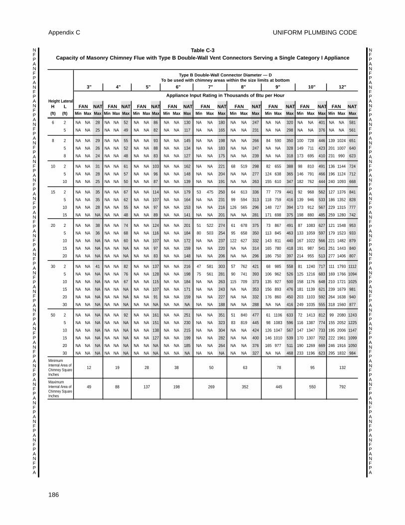
UNIFORM PLUMBING CODE
186
Appendix C
NFPANFPANFPANFPANFPANFPANFPANFPANFPANFPANFPANFPANFPANFPANFPANFPANFPANFPANFPANFPANFPANFPANFPA
NFPANFPANFPANFPANFPANFPANFPANFPANFPANFPANFPANFPANFPANFPANFPANFPANFPANFPANFPANFPANFPANFPANFPA
Table C-3 Capacity of Masonry Chimney Flue with Type B Double-Wall Vent Connectors Serving a Single Category I Appliance
Type B Double-Wall Connector Diameter — D To be used with chimney areas within the size limits at bottom
3" 4" 5" 6" 7" 8" 9" 10" 12"
Appliance Input Rating in Thousands of Btu per HourHeight Lateral
H L FAN NAT FAN NAT FAN NAT FAN NAT FAN NAT FAN NAT FAN NAT FAN NAT FAN NAT(ft) (ft) Min Max Max Min Max Max Min Max Max Min Max Max Min Max Max Min Max Max Min Max Max Min Max Max Min Max Max
6 2 NA NA 28 NA NA 52 NA NA 86 NA NA 130 NA NA 180 NA NA 247 NA NA 320 NA NA 401 NA NA 581
5 NA NA 25 NA NA 49 NA NA 82 NA NA 117 NA NA 165 NA NA 231 NA NA 298 NA NA 376 NA NA 561
8 2 NA NA 29 NA NA 55 NA NA 93 NA NA 145 NA NA 198 NA NA 266 84 590 350 100 728 446 139 1024 651
5 NA NA 26 NA NA 52 NA NA 88 NA NA 134 NA NA 183 NA NA 247 NA NA 328 149 711 423 201 1007 640
8 NA NA 24 NA NA 48 NA NA 83 NA NA 127 NA NA 175 NA NA 239 NA NA 318 173 695 410 231 990 623
10 2 NA NA 31 NA NA 61 NA NA 103 NA NA 162 NA NA 221 68 519 298 82 655 388 98 810 491 136 1144 724
5 NA NA 28 NA NA 57 NA NA 96 NA NA 148 NA NA 204 NA NA 277 124 638 365 146 791 466 196 1124 712
10 NA NA 25 NA NA 50 NA NA 87 NA NA 139 NA NA 191 NA NA 263 155 610 347 182 762 444 240 1093 668
15 2 NA NA 35 NA NA 67 NA NA 114 NA NA 179 53 475 250 64 613 336 77 779 441 92 968 562 127 1376 841
5 NA NA 35 NA NA 62 NA NA 107 NA NA 164 NA NA 231 99 594 313 118 759 416 139 946 533 186 1352 828
10 NA NA 28 NA NA 55 NA NA 97 NA NA 153 NA NA 216 126 565 296 148 727 394 173 912 567 229 1315 777
15 NA NA NA NA NA 48 NA NA 89 NA NA 141 NA NA 201 NA NA 281 171 698 375 198 880 485 259 1280 742
20 2 NA NA 38 NA NA 74 NA NA 124 NA NA 201 51 522 274 61 678 375 73 867 491 87 1083 627 121 1548 953
5 NA NA 36 NA NA 68 NA NA 116 NA NA 184 80 503 254 95 658 350 113 845 463 133 1059 597 179 1523 933
10 NA NA NA NA NA 60 NA NA 107 NA NA 172 NA NA 237 122 627 332 143 811 440 167 1022 566 221 1482 879
15 NA NA NA NA NA NA NA NA 97 NA NA 159 NA NA 220 NA NA 314 165 780 418 191 987 541 251 1443 840
20 NA NA NA NA NA NA NA NA 83 NA NA 148 NA NA 206 NA NA 296 186 750 397 214 955 513 277 1406 807
30 2 NA NA 41 NA NA 82 NA NA 137 NA NA 216 47 581 303 57 762 421 68 985 558 81 1240 717 111 1793 1112
5 NA NA NA NA NA 76 NA NA 128 NA NA 198 75 561 281 90 741 393 106 962 526 125 1216 683 169 1766 1094
10 NA NA NA NA NA 67 NA NA 115 NA NA 184 NA NA 263 115 709 373 135 927 500 158 1176 648 210 1721 1025
15 NA NA NA NA NA NA NA NA 107 NA NA 171 NA NA 243 NA NA 353 156 893 476 181 1139 621 239 1679 981
20 NA NA NA NA NA NA NA NA 91 NA NA 159 NA NA 227 NA NA 332 176 860 450 203 1103 592 264 1638 940
30 NA NA NA NA NA NA NA NA NA NA NA NA NA NA 188 NA NA 288 NA NA 416 249 1035 555 318 1560 877
50 2 NA NA NA NA NA 92 NA NA 161 NA NA 251 NA NA 351 51 840 477 61 1106 633 72 1413 812 99 2080 1243
5 NA NA NA NA NA NA NA NA 151 NA NA 230 NA NA 323 83 819 445 98 1083 596 116 1387 774 155 2052 1225
10 NA NA NA NA NA NA NA NA 138 NA NA 215 NA NA 304 NA NA 424 126 1047 567 147 1347 733 195 2006 1147
15 NA NA NA NA NA NA NA NA 127 NA NA 199 NA NA 282 NA NA 400 146 1010 539 170 1307 702 222 1961 1099
20 NA NA NA NA NA NA NA NA NA NA NA 185 NA NA 264 NA NA 376 165 977 511 190 1269 669 246 1916 1050
30 NA NA NA NA NA NA NA NA NA NA NA NA NA NA NA NA NA 327 NA NA 468 233 1196 623 295 1832 984
12 19 28 38 50 63 78 95 132
49 88 137 198 269 352 445 550 792
MinimumInternal Area ofChimney SquareInches
MaximumInternal Area ofChimney SquareInches
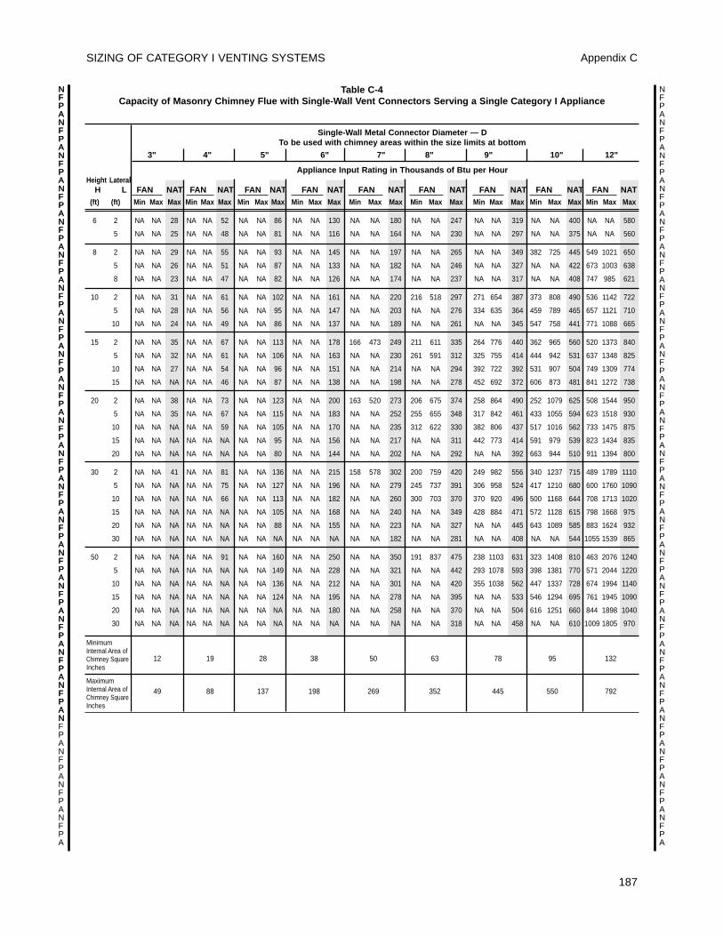
SIZING OF CATEGORY I VENTING SYSTEMS Appendix C
187
NFPANFPANFPANFPANFPANFPANFPANFPANFPANFPANFPANFPANFPANFPANFPANFPANFPANFPANFPANFPANFPANFPANFPA
NFPANFPANFPANFPANFPANFPANFPANFPANFPANFPANFPANFPANFPANFPANFPANFPANFPANFPANFPANFPANFPANFPANFPA
NFPANFPANFPANFPANFPANFPANFPANFPANFPANFPANFPANFPANFPANFPANFPANFPANFPANFPANFPAN
Table C-4 Capacity of Masonry Chimney Flue with Single-Wall Vent Connectors Serving a Single Category I Appliance
Single-Wall Metal Connector Diameter — D To be used with chimney areas within the size limits at bottom
3" 4" 5" 6" 7" 8" 9" 10" 12"
Appliance Input Rating in Thousands of Btu per HourHeight Lateral
H L FAN NAT FAN NAT FAN NAT FAN NAT FAN NAT FAN NAT FAN NAT FAN NAT FAN NAT(ft) (ft) Min Max Max Min Max Max Min Max Max Min Max Max Min Max Max Min Max Max Min Max Max Min Max Max Min Max Max
6 2 NA NA 28 NA NA 52 NA NA 86 NA NA 130 NA NA 180 NA NA 247 NA NA 319 NA NA 400 NA NA 580
5 NA NA 25 NA NA 48 NA NA 81 NA NA 116 NA NA 164 NA NA 230 NA NA 297 NA NA 375 NA NA 560
8 2 NA NA 29 NA NA 55 NA NA 93 NA NA 145 NA NA 197 NA NA 265 NA NA 349 382 725 445 549 1021 650
5 NA NA 26 NA NA 51 NA NA 87 NA NA 133 NA NA 182 NA NA 246 NA NA 327 NA NA 422 673 1003 638
8 NA NA 23 NA NA 47 NA NA 82 NA NA 126 NA NA 174 NA NA 237 NA NA 317 NA NA 408 747 985 621
10 2 NA NA 31 NA NA 61 NA NA 102 NA NA 161 NA NA 220 216 518 297 271 654 387 373 808 490 536 1142 722
5 NA NA 28 NA NA 56 NA NA 95 NA NA 147 NA NA 203 NA NA 276 334 635 364 459 789 465 657 1121 710
10 NA NA 24 NA NA 49 NA NA 86 NA NA 137 NA NA 189 NA NA 261 NA NA 345 547 758 441 771 1088 665
15 2 NA NA 35 NA NA 67 NA NA 113 NA NA 178 166 473 249 211 611 335 264 776 440 362 965 560 520 1373 840
5 NA NA 32 NA NA 61 NA NA 106 NA NA 163 NA NA 230 261 591 312 325 755 414 444 942 531 637 1348 825
10 NA NA 27 NA NA 54 NA NA 96 NA NA 151 NA NA 214 NA NA 294 392 722 392 531 907 504 749 1309 774
15 NA NA NA NA NA 46 NA NA 87 NA NA 138 NA NA 198 NA NA 278 452 692 372 606 873 481 841 1272 738
20 2 NA NA 38 NA NA 73 NA NA 123 NA NA 200 163 520 273 206 675 374 258 864 490 252 1079 625 508 1544 950
5 NA NA 35 NA NA 67 NA NA 115 NA NA 183 NA NA 252 255 655 348 317 842 461 433 1055 594 623 1518 930
10 NA NA NA NA NA 59 NA NA 105 NA NA 170 NA NA 235 312 622 330 382 806 437 517 1016 562 733 1475 875
15 NA NA NA NA NA NA NA NA 95 NA NA 156 NA NA 217 NA NA 311 442 773 414 591 979 539 823 1434 835
20 NA NA NA NA NA NA NA NA 80 NA NA 144 NA NA 202 NA NA 292 NA NA 392 663 944 510 911 1394 800
30 2 NA NA 41 NA NA 81 NA NA 136 NA NA 215 158 578 302 200 759 420 249 982 556 340 1237 715 489 1789 1110
5 NA NA NA NA NA 75 NA NA 127 NA NA 196 NA NA 279 245 737 391 306 958 524 417 1210 680 600 1760 1090
10 NA NA NA NA NA 66 NA NA 113 NA NA 182 NA NA 260 300 703 370 370 920 496 500 1168 644 708 1713 1020
15 NA NA NA NA NA NA NA NA 105 NA NA 168 NA NA 240 NA NA 349 428 884 471 572 1128 615 798 1668 975
20 NA NA NA NA NA NA NA NA 88 NA NA 155 NA NA 223 NA NA 327 NA NA 445 643 1089 585 883 1624 932
30 NA NA NA NA NA NA NA NA NA NA NA NA NA NA 182 NA NA 281 NA NA 408 NA NA 544 1055 1539 865
50 2 NA NA NA NA NA 91 NA NA 160 NA NA 250 NA NA 350 191 837 475 238 1103 631 323 1408 810 463 2076 1240
5 NA NA NA NA NA NA NA NA 149 NA NA 228 NA NA 321 NA NA 442 293 1078 593 398 1381 770 571 2044 1220
10 NA NA NA NA NA NA NA NA 136 NA NA 212 NA NA 301 NA NA 420 355 1038 562 447 1337 728 674 1994 1140
15 NA NA NA NA NA NA NA NA 124 NA NA 195 NA NA 278 NA NA 395 NA NA 533 546 1294 695 761 1945 1090
20 NA NA NA NA NA NA NA NA NA NA NA 180 NA NA 258 NA NA 370 NA NA 504 616 1251 660 844 1898 1040
30 NA NA NA NA NA NA NA NA NA NA NA NA NA NA NA NA NA 318 NA NA 458 NA NA 610 1009 1805 970
12 19 28 38 50 63 78 95 132
49 88 137 198 269 352 445 550 792
MinimumInternal Area ofChimney SquareInches
MaximumInternal Area ofChimney SquareInches
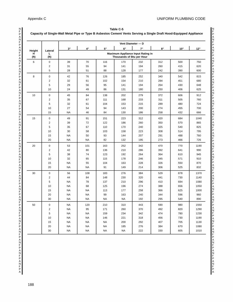
UNIFORM PLUMBING CODE
188
Appendix C
NFPANFPANFPANFPANFPANFPANFPANFPANFPANFPANFPANFPANFPANFPANFPANFPANFPANFPANFPANFPANFPANFPANFPA
NFPANFPANFPANFPANFPANFPANFPANFPANFPANFPANFPANFPANFPANFPANFPANFPANFPANFPANFPANFPANFPANFPANFPA
Table C-5 Capacity of Single-Wall Metal Pipe or Type B Asbestos Cement Vents Serving a Single Draft Hood-Equipped Appliance
Vent Diameter — D
Height Lateral3" 4" 5" 6" 7" 8" 10" 12"
H L Maximum Appliance Input Rating in(ft) (ft) Thousands of Btu per Hour
6 0 39 70 116 170 232 312 500 750
2 31 55 94 141 194 260 415 620
5 28 51 88 128 177 242 390 600
8 0 42 76 126 185 252 340 542 815
2 32 61 102 154 210 284 451 680
5 29 56 95 141 194 264 430 648
10 24 49 86 131 180 250 406 625
10 0 45 84 138 202 279 372 606 912
2 35 67 111 168 233 311 505 760
5 32 61 104 153 215 289 480 724
10 27 54 94 143 200 274 455 700
15 NA 46 84 130 186 258 432 666
15 0 49 91 151 223 312 420 684 1040
2 39 72 122 186 260 350 570 865
5 35 67 110 170 240 325 540 825
10 30 58 103 158 223 308 514 795
15 NA 50 93 144 207 291 488 760
20 NA NA 82 132 195 273 466 726
20 0 53 101 163 252 342 470 770 1190
2 42 80 136 210 286 392 641 990
5 38 74 123 192 264 364 610 945
10 32 65 115 178 246 345 571 910
15 NA 55 104 163 228 326 550 870
20 NA NA 91 149 214 306 525 832
30 0 56 108 183 276 384 529 878 1370
2 44 84 148 230 320 441 730 1140
5 NA 78 137 210 296 410 694 1080
10 NA 68 125 196 274 388 656 1050
15 NA NA 113 177 258 366 625 1000
20 NA NA 99 163 240 344 596 960
30 NA NA NA NA 192 295 540 890
50 0 NA 120 210 310 443 590 980 1550
2 NA 95 171 260 370 492 820 1290
5 NA NA 159 234 342 474 780 1230
10 NA NA 146 221 318 456 730 1190
15 NA NA NA 200 292 407 705 1130
20 NA NA NA 185 276 384 670 1080
30 NA NA NA NA 222 330 605 1010
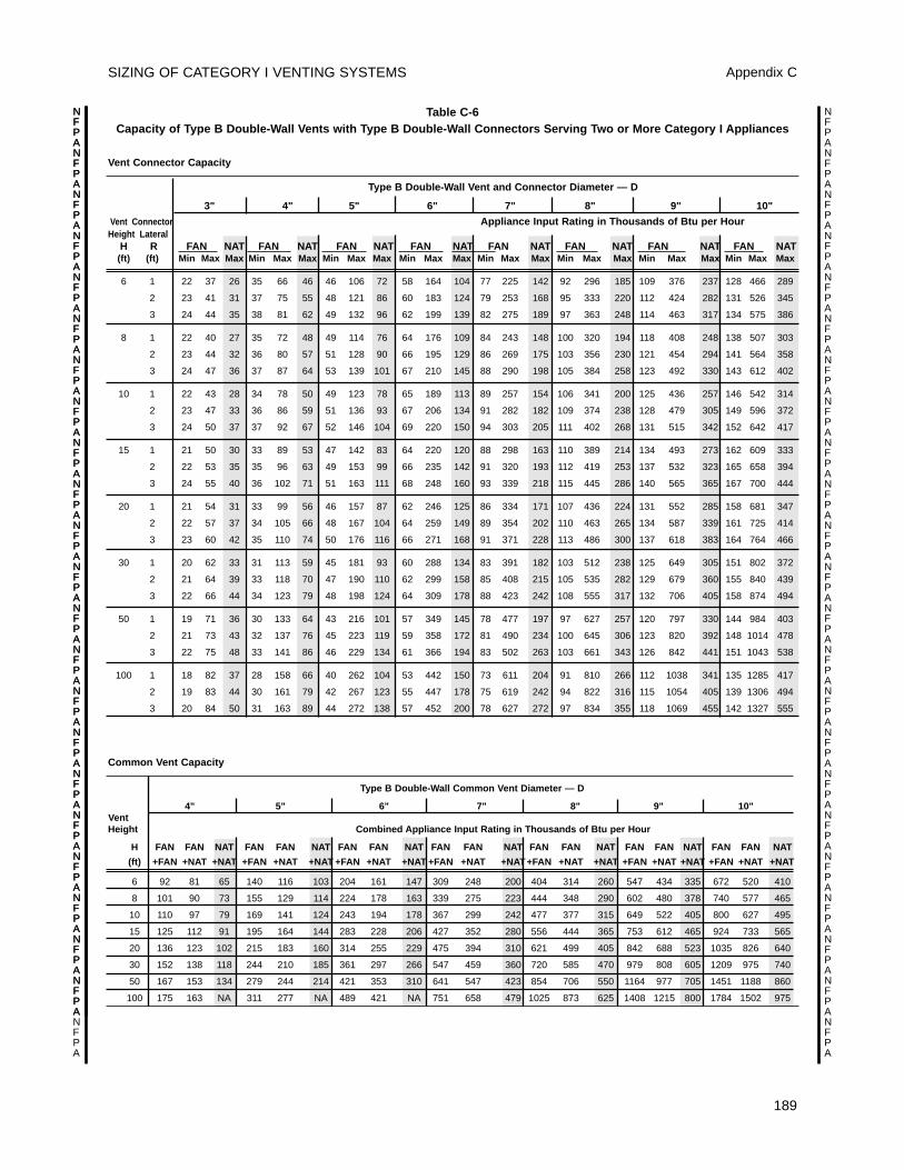
SIZING OF CATEGORY I VENTING SYSTEMS Appendix C
NFPANFPANFPANFPANFPANFPANFPANFPANFPANFPANFPANFPANFPANFPANFPANFPANFPANFPANFPANFPANFPANFPANFPA
NFPANFPANFPANFPANFPANFPANFPANFPANFPANFPANFPANFPANFPANFPANFPANFPANFPANFPANFPANFPANFPANFPANFPA
NFPANFPANFPANFPANFPANFPANFPANFPANFPANFPANFPANFPANFPANFPANFPANFPANFPANFPANFPANFPANFPANFPA
Table C-6 Capacity of Type B Double-Wall Vents with Type B Double-Wall Connectors Serving Two or More Category I Appliances
Vent Connector Capacity
Type B Double-Wall Vent and Connector Diameter — D
3" 4" 5" 6" 7" 8" 9" 10"
Vent Connector Appliance Input Rating in Thousands of Btu per HourHeight Lateral
H R FAN NAT FAN NAT FAN NAT FAN NAT FAN NAT FAN NAT FAN NAT FAN NAT(ft) (ft) Min Max Max Min Max Max Min Max Max Min Max Max Min Max Max Min Max Max Min Max Max Min Max Max
6 1 22 37 26 35 66 46 46 106 72 58 164 104 77 225 142 92 296 185 109 376 237 128 466 289
2 23 41 31 37 75 55 48 121 86 60 183 124 79 253 168 95 333 220 112 424 282 131 526 345
3 24 44 35 38 81 62 49 132 96 62 199 139 82 275 189 97 363 248 114 463 317 134 575 386
8 1 22 40 27 35 72 48 49 114 76 64 176 109 84 243 148 100 320 194 118 408 248 138 507 303
2 23 44 32 36 80 57 51 128 90 66 195 129 86 269 175 103 356 230 121 454 294 141 564 358
3 24 47 36 37 87 64 53 139 101 67 210 145 88 290 198 105 384 258 123 492 330 143 612 402
10 1 22 43 28 34 78 50 49 123 78 65 189 113 89 257 154 106 341 200 125 436 257 146 542 314
2 23 47 33 36 86 59 51 136 93 67 206 134 91 282 182 109 374 238 128 479 305 149 596 372
3 24 50 37 37 92 67 52 146 104 69 220 150 94 303 205 111 402 268 131 515 342 152 642 417
15 1 21 50 30 33 89 53 47 142 83 64 220 120 88 298 163 110 389 214 134 493 273 162 609 333
2 22 53 35 35 96 63 49 153 99 66 235 142 91 320 193 112 419 253 137 532 323 165 658 394
3 24 55 40 36 102 71 51 163 111 68 248 160 93 339 218 115 445 286 140 565 365 167 700 444
20 1 21 54 31 33 99 56 46 157 87 62 246 125 86 334 171 107 436 224 131 552 285 158 681 347
2 22 57 37 34 105 66 48 167 104 64 259 149 89 354 202 110 463 265 134 587 339 161 725 414
3 23 60 42 35 110 74 50 176 116 66 271 168 91 371 228 113 486 300 137 618 383 164 764 466
30 1 20 62 33 31 113 59 45 181 93 60 288 134 83 391 182 103 512 238 125 649 305 151 802 372
2 21 64 39 33 118 70 47 190 110 62 299 158 85 408 215 105 535 282 129 679 360 155 840 439
3 22 66 44 34 123 79 48 198 124 64 309 178 88 423 242 108 555 317 132 706 405 158 874 494
50 1 19 71 36 30 133 64 43 216 101 57 349 145 78 477 197 97 627 257 120 797 330 144 984 403
2 21 73 43 32 137 76 45 223 119 59 358 172 81 490 234 100 645 306 123 820 392 148 1014 478
3 22 75 48 33 141 86 46 229 134 61 366 194 83 502 263 103 661 343 126 842 441 151 1043 538
100 1 18 82 37 28 158 66 40 262 104 53 442 150 73 611 204 91 810 266 112 1038 341 135 1285 417
2 19 83 44 30 161 79 42 267 123 55 447 178 75 619 242 94 822 316 115 1054 405 139 1306 494
3 20 84 50 31 163 89 44 272 138 57 452 200 78 627 272 97 834 355 118 1069 455 142 1327 555
189
Common Vent Capacity
Type B Double-Wall Common Vent Diameter — D
4" 5" 6" 7" 8" 9" 10"VentHeight Combined Appliance Input Rating in Thousands of Btu per Hour
H FAN FAN NAT FAN FAN NAT FAN FAN NAT FAN FAN NAT FAN FAN NAT FAN FAN NAT FAN FAN NAT
(ft) +FAN +NAT +NAT +FAN +NAT +NAT +FAN +NAT +NAT +FAN +NAT +NAT+FAN +NAT +NAT +FAN +NAT +NAT +FAN +NAT +NAT
6 92 81 65 140 116 103 204 161 147 309 248 200 404 314 260 547 434 335 672 520 410
8 101 90 73 155 129 114 224 178 163 339 275 223 444 348 290 602 480 378 740 577 465
10 110 97 79 169 141 124 243 194 178 367 299 242 477 377 315 649 522 405 800 627 495
15 125 112 91 195 164 144 283 228 206 427 352 280 556 444 365 753 612 465 924 733 565
20 136 123 102 215 183 160 314 255 229 475 394 310 621 499 405 842 688 523 1035 826 640
30 152 138 118 244 210 185 361 297 266 547 459 360 720 585 470 979 808 605 1209 975 740
50 167 153 134 279 244 214 421 353 310 641 547 423 854 706 550 1164 977 705 1451 1188 860
100 175 163 NA 311 277 NA 489 421 NA 751 658 479 1025 873 625 1408 1215 800 1784 1502 975
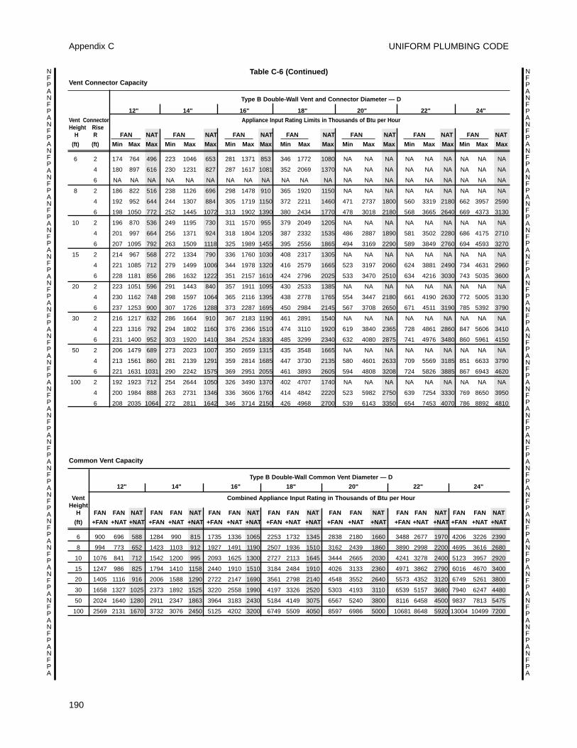
UNIFORM PLUMBING CODE
190
Appendix C
NFPANFPANFPANFPANFPANFPANFPANFPANFPANFPANFPANFPANFPANFPANFPANFPANFPANFPANFPANFPANFPANFPANFPA
NFPANFPANFPANFPANFPANFPANFPANFPANFPANFPANFPANFPANFPANFPANFPANFPANFPANFPANFPANFPANFPANFPANFPA
Common Vent Capacity
Type B Double-Wall Common Vent Diameter — D
12" 14" 16" 18" 20" 22" 24"
Vent Combined Appliance Input Rating in Thousands of Btu per HourHeight
H FAN FAN NAT FAN FAN NAT FAN FAN NAT FAN FAN NAT FAN FAN NAT FAN FAN NAT FAN FAN NAT
(ft) +FAN +NAT +NAT +FAN +NAT +NAT +FAN +NAT +NAT +FAN +NAT +NAT +FAN +NAT +NAT +FAN +NAT +NAT +FAN +NAT +NAT
6 900 696 588 1284 990 815 1735 1336 1065 2253 1732 1345 2838 2180 1660 3488 2677 1970 4206 3226 2390
8 994 773 652 1423 1103 912 1927 1491 1190 2507 1936 1510 3162 2439 1860 3890 2998 2200 4695 3616 2680
10 1076 841 712 1542 1200 995 2093 1625 1300 2727 2113 1645 3444 2665 2030 4241 3278 2400 5123 3957 2920
15 1247 986 825 1794 1410 1158 2440 1910 1510 3184 2484 1910 4026 3133 2360 4971 3862 2790 6016 4670 3400
20 1405 1116 916 2006 1588 1290 2722 2147 1690 3561 2798 2140 4548 3552 2640 5573 4352 3120 6749 5261 3800
30 1658 1327 1025 2373 1892 1525 3220 2558 1990 4197 3326 2520 5303 4193 3110 6539 5157 3680 7940 6247 4480
50 2024 1640 1280 2911 2347 1863 3964 3183 2430 5184 4149 3075 6567 5240 3800 8116 6458 4500 9837 7813 5475
100 2569 2131 1670 3732 3076 2450 5125 4202 3200 6749 5509 4050 8597 6986 5000 10681 8648 5920 13004 10499 7200
Table C-6 (Continued)Vent Connector Capacity
Type B Double-Wall Vent and Connector Diameter — D
12" 14" 16" 18" 20" 22" 24"
Vent Connector Appliance Input Rating Limits in Thousands of Btu per HourHeight Rise
H R FAN NAT FAN NAT FAN NAT FAN NAT FAN NAT FAN NAT FAN NAT
(ft) (ft) Min Max Max Min Max Max Min Max Max Min Max Max Min Max Max Min Max Max Min Max Max
6 2 174 764 496 223 1046 653 281 1371 853 346 1772 1080 NA NA NA NA NA NA NA NA NA
4 180 897 616 230 1231 827 287 1617 1081 352 2069 1370 NA NA NA NA NA NA NA NA NA
6 NA NA NA NA NA NA NA NA NA NA NA NA NA NA NA NA NA NA NA NA NA
8 2 186 822 516 238 1126 696 298 1478 910 365 1920 1150 NA NA NA NA NA NA NA NA NA
4 192 952 644 244 1307 884 305 1719 1150 372 2211 1460 471 2737 1800 560 3319 2180 662 3957 2590
6 198 1050 772 252 1445 1072 313 1902 1390 380 2434 1770 478 3018 2180 568 3665 2640 669 4373 3130
10 2 196 870 536 249 1195 730 311 1570 955 379 2049 1205 NA NA NA NA NA NA NA NA NA
4 201 997 664 256 1371 924 318 1804 1205 387 2332 1535 486 2887 1890 581 3502 2280 686 4175 2710
6 207 1095 792 263 1509 1118 325 1989 1455 395 2556 1865 494 3169 2290 589 3849 2760 694 4593 3270
15 2 214 967 568 272 1334 790 336 1760 1030 408 2317 1305 NA NA NA NA NA NA NA NA NA
4 221 1085 712 279 1499 1006 344 1978 1320 416 2579 1665 523 3197 2060 624 3881 2490 734 4631 2960
6 228 1181 856 286 1632 1222 351 2157 1610 424 2796 2025 533 3470 2510 634 4216 3030 743 5035 3600
20 2 223 1051 596 291 1443 840 357 1911 1095 430 2533 1385 NA NA NA NA NA NA NA NA NA
4 230 1162 748 298 1597 1064 365 2116 1395 438 2778 1765 554 3447 2180 661 4190 2630 772 5005 3130
6 237 1253 900 307 1726 1288 373 2287 1695 450 2984 2145 567 3708 2650 671 4511 3190 785 5392 3790
30 2 216 1217 632 286 1664 910 367 2183 1190 461 2891 1540 NA NA NA NA NA NA NA NA NA
4 223 1316 792 294 1802 1160 376 2366 1510 474 3110 1920 619 3840 2365 728 4861 2860 847 5606 3410
6 231 1400 952 303 1920 1410 384 2524 1830 485 3299 2340 632 4080 2875 741 4976 3480 860 5961 4150
50 2 206 1479 689 273 2023 1007 350 2659 1315 435 3548 1665 NA NA NA NA NA NA NA NA NA
4 213 1561 860 281 2139 1291 359 2814 1685 447 3730 2135 580 4601 2633 709 5569 3185 851 6633 3790
6 221 1631 1031 290 2242 1575 369 2951 2055 461 3893 2605 594 4808 3208 724 5826 3885 867 6943 4620
100 2 192 1923 712 254 2644 1050 326 3490 1370 402 4707 1740 NA NA NA NA NA NA NA NA NA
4 200 1984 888 263 2731 1346 336 3606 1760 414 4842 2220 523 5982 2750 639 7254 3330 769 8650 3950
6 208 2035 1064 272 2811 1642 346 3714 2150 426 4968 2700 539 6143 3350 654 7453 4070 786 8892 4810
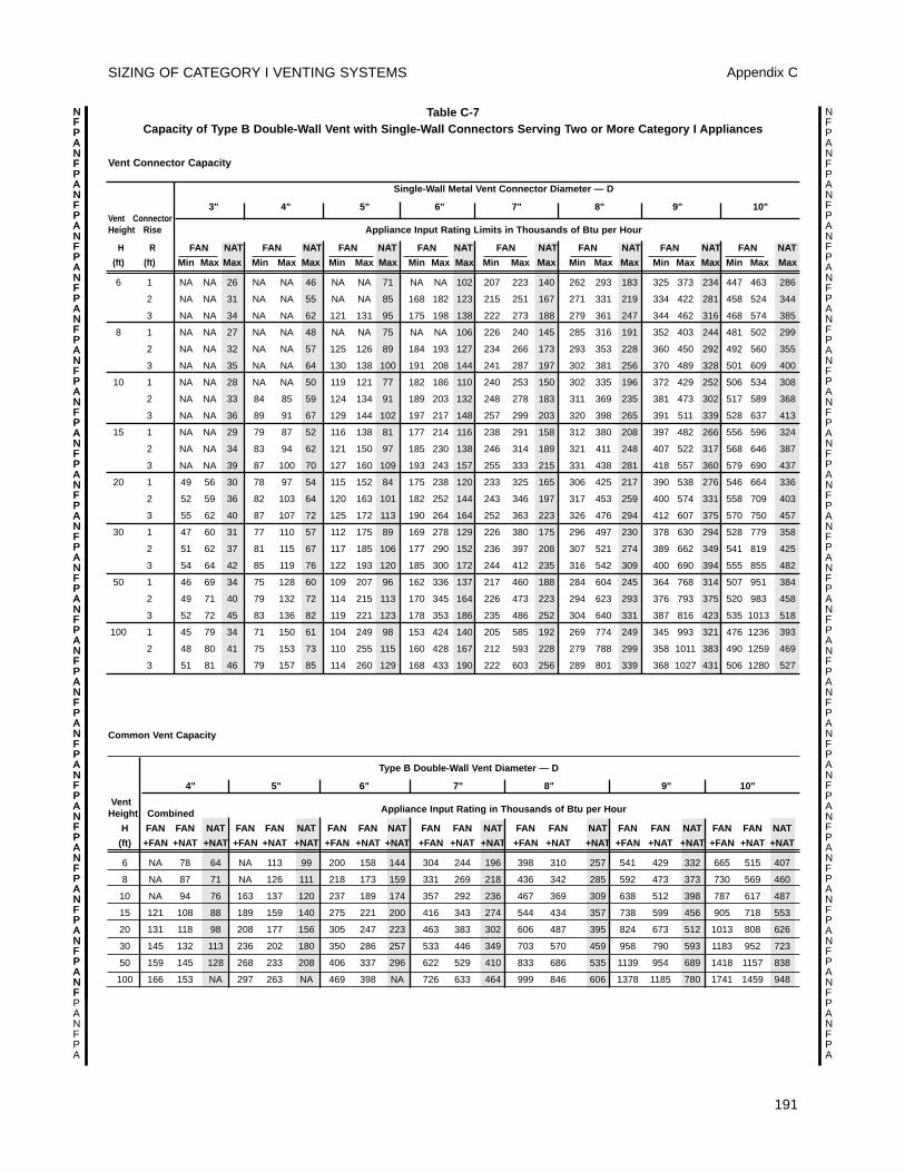
SIZING OF CATEGORY I VENTING SYSTEMS Appendix C
191
NFPANFPANFPANFPANFPANFPANFPANFPANFPANFPANFPANFPANFPANFPANFPANFPANFPANFPANFPANFPANFPANFPANFPA
NFPANFPANFPANFPANFPANFPANFPANFPANFPANFPANFPANFPANFPANFPANFPANFPANFPANFPANFPANFPANFPANFPANFPA
NFPANFPANFPANFPANFPANFPANFPANFPANFPANFPANFPANFPANFPANFPANFPANFPANFPANFPANFPANFPANFPANF
Common Vent Capacity
Type B Double-Wall Vent Diameter — D
4" 5" 6" 7" 8" 9" 10"
VentHeight Combined Appliance Input Rating in Thousands of Btu per Hour
H FAN FAN NAT FAN FAN NAT FAN FAN NAT FAN FAN NAT FAN FAN NAT FAN FAN NAT FAN FAN NAT
(ft) +FAN +NAT +NAT +FAN +NAT +NAT +FAN +NAT +NAT +FAN +NAT +NAT +FAN +NAT +NAT +FAN +NAT +NAT +FAN +NAT +NAT
6 NA 78 64 NA 113 99 200 158 144 304 244 196 398 310 257 541 429 332 665 515 407
8 NA 87 71 NA 126 111 218 173 159 331 269 218 436 342 285 592 473 373 730 569 460
10 NA 94 76 163 137 120 237 189 174 357 292 236 467 369 309 638 512 398 787 617 487
15 121 108 88 189 159 140 275 221 200 416 343 274 544 434 357 738 599 456 905 718 553
20 131 118 98 208 177 156 305 247 223 463 383 302 606 487 395 824 673 512 1013 808 626
30 145 132 113 236 202 180 350 286 257 533 446 349 703 570 459 958 790 593 1183 952 723
50 159 145 128 268 233 208 406 337 296 622 529 410 833 686 535 1139 954 689 1418 1157 838
100 166 153 NA 297 263 NA 469 398 NA 726 633 464 999 846 606 1378 1185 780 1741 1459 948
Table C-7 Capacity of Type B Double-Wall Vent with Single-Wall Connectors Serving Two or More Category I Appliances
Vent Connector Capacity
Single-Wall Metal Vent Connector Diameter — D
3" 4" 5" 6" 7" 8" 9" 10"Vent ConnectorHeight Rise Appliance Input Rating Limits in Thousands of Btu per Hour
H R FAN NAT FAN NAT FAN NAT FAN NAT FAN NAT FAN NAT FAN NAT FAN NAT
(ft) (ft) Min Max Max Min Max Max Min Max Max Min Max Max Min Max Max Min Max Max Min Max Max Min Max Max
6 1 NA NA 26 NA NA 46 NA NA 71 NA NA 102 207 223 140 262 293 183 325 373 234 447 463 286
2 NA NA 31 NA NA 55 NA NA 85 168 182 123 215 251 167 271 331 219 334 422 281 458 524 344
3 NA NA 34 NA NA 62 121 131 95 175 198 138 222 273 188 279 361 247 344 462 316 468 574 385
8 1 NA NA 27 NA NA 48 NA NA 75 NA NA 106 226 240 145 285 316 191 352 403 244 481 502 299
2 NA NA 32 NA NA 57 125 126 89 184 193 127 234 266 173 293 353 228 360 450 292 492 560 355
3 NA NA 35 NA NA 64 130 138 100 191 208 144 241 287 197 302 381 256 370 489 328 501 609 400
10 1 NA NA 28 NA NA 50 119 121 77 182 186 110 240 253 150 302 335 196 372 429 252 506 534 308
2 NA NA 33 84 85 59 124 134 91 189 203 132 248 278 183 311 369 235 381 473 302 517 589 368
3 NA NA 36 89 91 67 129 144 102 197 217 148 257 299 203 320 398 265 391 511 339 528 637 413
15 1 NA NA 29 79 87 52 116 138 81 177 214 116 238 291 158 312 380 208 397 482 266 556 596 324
2 NA NA 34 83 94 62 121 150 97 185 230 138 246 314 189 321 411 248 407 522 317 568 646 387
3 NA NA 39 87 100 70 127 160 109 193 243 157 255 333 215 331 438 281 418 557 360 579 690 437
20 1 49 56 30 78 97 54 115 152 84 175 238 120 233 325 165 306 425 217 390 538 276 546 664 336
2 52 59 36 82 103 64 120 163 101 182 252 144 243 346 197 317 453 259 400 574 331 558 709 403
3 55 62 40 87 107 72 125 172 113 190 264 164 252 363 223 326 476 294 412 607 375 570 750 457
30 1 47 60 31 77 110 57 112 175 89 169 278 129 226 380 175 296 497 230 378 630 294 528 779 358
2 51 62 37 81 115 67 117 185 106 177 290 152 236 397 208 307 521 274 389 662 349 541 819 425
3 54 64 42 85 119 76 122 193 120 185 300 172 244 412 235 316 542 309 400 690 394 555 855 482
50 1 46 69 34 75 128 60 109 207 96 162 336 137 217 460 188 284 604 245 364 768 314 507 951 384
2 49 71 40 79 132 72 114 215 113 170 345 164 226 473 223 294 623 293 376 793 375 520 983 458
3 52 72 45 83 136 82 119 221 123 178 353 186 235 486 252 304 640 331 387 816 423 535 1013 518
100 1 45 79 34 71 150 61 104 249 98 153 424 140 205 585 192 269 774 249 345 993 321 476 1236 393
2 48 80 41 75 153 73 110 255 115 160 428 167 212 593 228 279 788 299 358 1011 383 490 1259 469
3 51 81 46 79 157 85 114 260 129 168 433 190 222 603 256 289 801 339 368 1027 431 506 1280 527
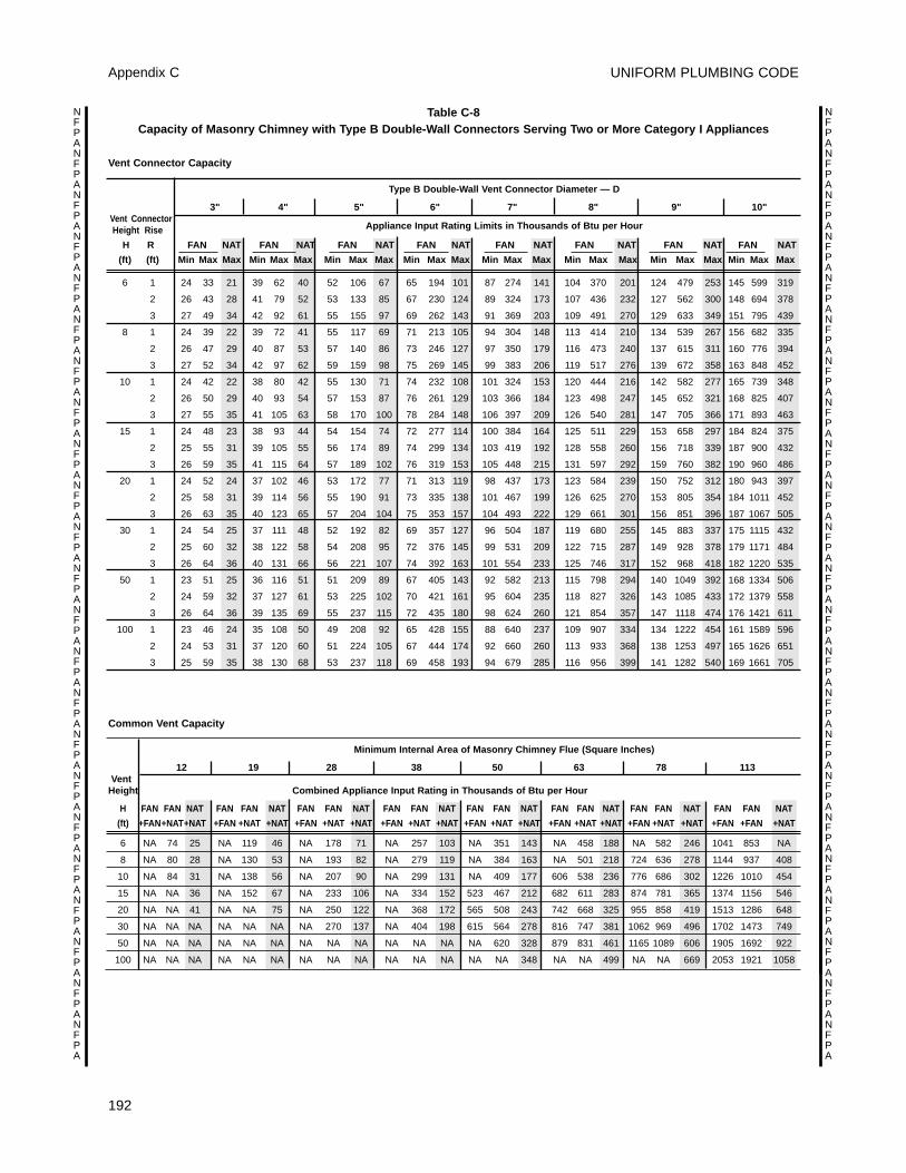
UNIFORM PLUMBING CODE
192
Appendix C
NFPANFPANFPANFPANFPANFPANFPANFPANFPANFPANFPANFPANFPANFPANFPANFPANFPANFPANFPANFPANFPANFPANFPA
NFPANFPANFPANFPANFPANFPANFPANFPANFPANFPANFPANFPANFPANFPANFPANFPANFPANFPANFPANFPANFPANFPANFPA
Table C-8 Capacity of Masonry Chimney with Type B Double-Wall Connectors Serving Two or More Category I Appliances
Vent Connector Capacity
Type B Double-Wall Vent Connector Diameter — D
3" 4" 5" 6" 7" 8" 9" 10"Vent ConnectorHeight Rise Appliance Input Rating Limits in Thousands of Btu per Hour
H R FAN NAT FAN NAT FAN NAT FAN NAT FAN NAT FAN NAT FAN NAT FAN NAT
(ft) (ft) Min Max Max Min Max Max Min Max Max Min Max Max Min Max Max Min Max Max Min Max Max Min Max Max
6 1 24 33 21 39 62 40 52 106 67 65 194 101 87 274 141 104 370 201 124 479 253 145 599 319
2 26 43 28 41 79 52 53 133 85 67 230 124 89 324 173 107 436 232 127 562 300 148 694 378
3 27 49 34 42 92 61 55 155 97 69 262 143 91 369 203 109 491 270 129 633 349 151 795 439
8 1 24 39 22 39 72 41 55 117 69 71 213 105 94 304 148 113 414 210 134 539 267 156 682 335
2 26 47 29 40 87 53 57 140 86 73 246 127 97 350 179 116 473 240 137 615 311 160 776 394
3 27 52 34 42 97 62 59 159 98 75 269 145 99 383 206 119 517 276 139 672 358 163 848 452
10 1 24 42 22 38 80 42 55 130 71 74 232 108 101 324 153 120 444 216 142 582 277 165 739 348
2 26 50 29 40 93 54 57 153 87 76 261 129 103 366 184 123 498 247 145 652 321 168 825 407
3 27 55 35 41 105 63 58 170 100 78 284 148 106 397 209 126 540 281 147 705 366 171 893 463
15 1 24 48 23 38 93 44 54 154 74 72 277 114 100 384 164 125 511 229 153 658 297 184 824 375
2 25 55 31 39 105 55 56 174 89 74 299 134 103 419 192 128 558 260 156 718 339 187 900 432
3 26 59 35 41 115 64 57 189 102 76 319 153 105 448 215 131 597 292 159 760 382 190 960 486
20 1 24 52 24 37 102 46 53 172 77 71 313 119 98 437 173 123 584 239 150 752 312 180 943 397
2 25 58 31 39 114 56 55 190 91 73 335 138 101 467 199 126 625 270 153 805 354 184 1011 452
3 26 63 35 40 123 65 57 204 104 75 353 157 104 493 222 129 661 301 156 851 396 187 1067 505
30 1 24 54 25 37 111 48 52 192 82 69 357 127 96 504 187 119 680 255 145 883 337 175 1115 432
2 25 60 32 38 122 58 54 208 95 72 376 145 99 531 209 122 715 287 149 928 378 179 1171 484
3 26 64 36 40 131 66 56 221 107 74 392 163 101 554 233 125 746 317 152 968 418 182 1220 535
50 1 23 51 25 36 116 51 51 209 89 67 405 143 92 582 213 115 798 294 140 1049 392 168 1334 506
2 24 59 32 37 127 61 53 225 102 70 421 161 95 604 235 118 827 326 143 1085 433 172 1379 558
3 26 64 36 39 135 69 55 237 115 72 435 180 98 624 260 121 854 357 147 1118 474 176 1421 611
100 1 23 46 24 35 108 50 49 208 92 65 428 155 88 640 237 109 907 334 134 1222 454 161 1589 596
2 24 53 31 37 120 60 51 224 105 67 444 174 92 660 260 113 933 368 138 1253 497 165 1626 651
3 25 59 35 38 130 68 53 237 118 69 458 193 94 679 285 116 956 399 141 1282 540 169 1661 705
Common Vent Capacity
Minimum Internal Area of Masonry Chimney Flue (Square Inches)
12 19 28 38 50 63 78 113Vent
Height Combined Appliance Input Rating in Thousands of Btu per Hour
H FAN FAN NAT FAN FAN NAT FAN FAN NAT FAN FAN NAT FAN FAN NAT FAN FAN NAT FAN FAN NAT FAN FAN NAT
(ft) +FAN+NAT+NAT +FAN +NAT +NAT +FAN +NAT +NAT +FAN +NAT +NAT +FAN +NAT +NAT +FAN +NAT +NAT +FAN +NAT +NAT +FAN +FAN +NAT
6 NA 74 25 NA 119 46 NA 178 71 NA 257 103 NA 351 143 NA 458 188 NA 582 246 1041 853 NA
8 NA 80 28 NA 130 53 NA 193 82 NA 279 119 NA 384 163 NA 501 218 724 636 278 1144 937 408
10 NA 84 31 NA 138 56 NA 207 90 NA 299 131 NA 409 177 606 538 236 776 686 302 1226 1010 454
15 NA NA 36 NA 152 67 NA 233 106 NA 334 152 523 467 212 682 611 283 874 781 365 1374 1156 546
20 NA NA 41 NA NA 75 NA 250 122 NA 368 172 565 508 243 742 668 325 955 858 419 1513 1286 648
30 NA NA NA NA NA NA NA 270 137 NA 404 198 615 564 278 816 747 381 1062 969 496 1702 1473 749
50 NA NA NA NA NA NA NA NA NA NA NA NA NA 620 328 879 831 461 1165 1089 606 1905 1692 922
100 NA NA NA NA NA NA NA NA NA NA NA NA NA NA 348 NA NA 499 NA NA 669 2053 1921 1058
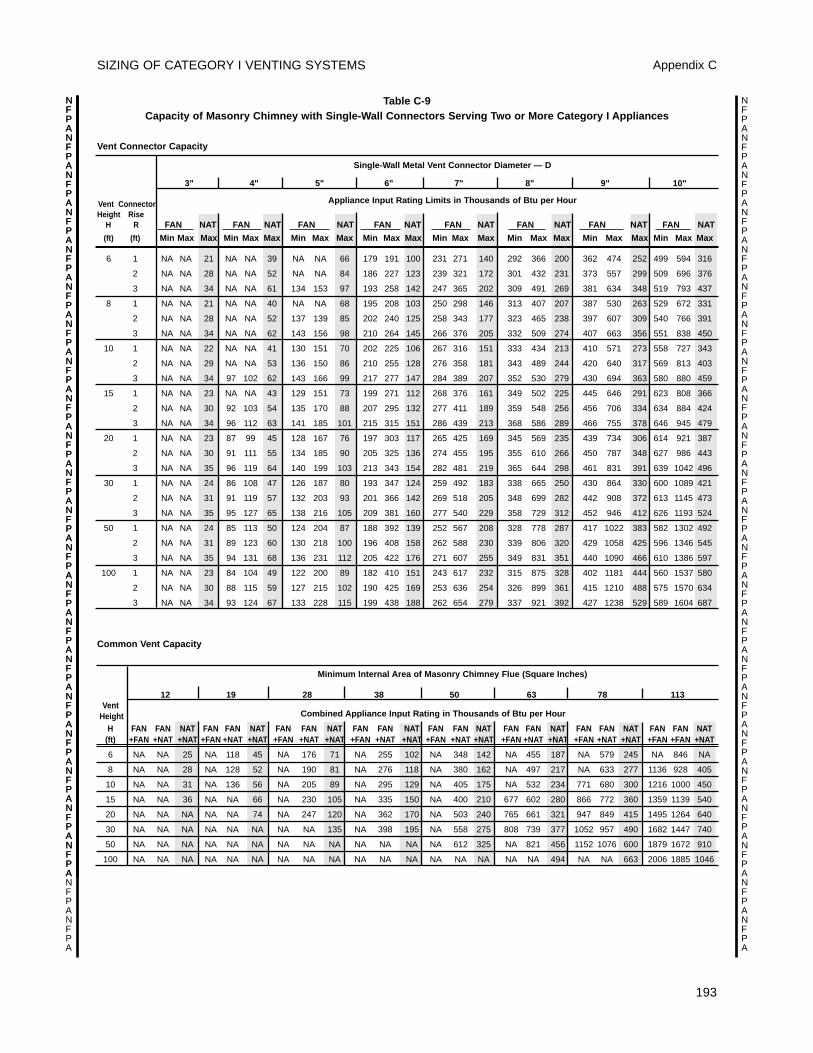
SIZING OF CATEGORY I VENTING SYSTEMS Appendix C
193
NFPANFPANFPANFPANFPANFPANFPANFPANFPANFPANFPANFPANFPANFPANFPANFPANFPANFPANFPANFPANFPANFPANFPA
NFPANFPANFPANFPANFPANFPANFPANFPANFPANFPANFPANFPANFPANFPANFPANFPANFPANFPANFPANFPANFPANFPANFPA
NFPANFPANFPANFPANFPANFPANFPANFPANFPANFPANFPANFPANFPANFPANFPANFPANFPANFPANFPANFPANFPA
Table C-9 Capacity of Masonry Chimney with Single-Wall Connectors Serving Two or More Category I Appliances
Vent Connector Capacity
Single-Wall Metal Vent Connector Diameter — D
3" 4" 5" 6" 7" 8" 9" 10"
Appliance Input Rating Limits in Thousands of Btu per HourVent ConnectorHeight Rise
H R FAN NAT FAN NAT FAN NAT FAN NAT FAN NAT FAN NAT FAN NAT FAN NAT
(ft) (ft) Min Max Max Min Max Max Min Max Max Min Max Max Min Max Max Min Max Max Min Max Max Min Max Max
6 1 NA NA 21 NA NA 39 NA NA 66 179 191 100 231 271 140 292 366 200 362 474 252 499 594 316
2 NA NA 28 NA NA 52 NA NA 84 186 227 123 239 321 172 301 432 231 373 557 299 509 696 376
3 NA NA 34 NA NA 61 134 153 97 193 258 142 247 365 202 309 491 269 381 634 348 519 793 437
8 1 NA NA 21 NA NA 40 NA NA 68 195 208 103 250 298 146 313 407 207 387 530 263 529 672 331
2 NA NA 28 NA NA 52 137 139 85 202 240 125 258 343 177 323 465 238 397 607 309 540 766 391
3 NA NA 34 NA NA 62 143 156 98 210 264 145 266 376 205 332 509 274 407 663 356 551 838 450
10 1 NA NA 22 NA NA 41 130 151 70 202 225 106 267 316 151 333 434 213 410 571 273 558 727 343
2 NA NA 29 NA NA 53 136 150 86 210 255 128 276 358 181 343 489 244 420 640 317 569 813 403
3 NA NA 34 97 102 62 143 166 99 217 277 147 284 389 207 352 530 279 430 694 363 580 880 459
15 1 NA NA 23 NA NA 43 129 151 73 199 271 112 268 376 161 349 502 225 445 646 291 623 808 366
2 NA NA 30 92 103 54 135 170 88 207 295 132 277 411 189 359 548 256 456 706 334 634 884 424
3 NA NA 34 96 112 63 141 185 101 215 315 151 286 439 213 368 586 289 466 755 378 646 945 479
20 1 NA NA 23 87 99 45 128 167 76 197 303 117 265 425 169 345 569 235 439 734 306 614 921 387
2 NA NA 30 91 111 55 134 185 90 205 325 136 274 455 195 355 610 266 450 787 348 627 986 443
3 NA NA 35 96 119 64 140 199 103 213 343 154 282 481 219 365 644 298 461 831 391 639 1042 496
30 1 NA NA 24 86 108 47 126 187 80 193 347 124 259 492 183 338 665 250 430 864 330 600 1089 421
2 NA NA 31 91 119 57 132 203 93 201 366 142 269 518 205 348 699 282 442 908 372 613 1145 473
3 NA NA 35 95 127 65 138 216 105 209 381 160 277 540 229 358 729 312 452 946 412 626 1193 524
50 1 NA NA 24 85 113 50 124 204 87 188 392 139 252 567 208 328 778 287 417 1022 383 582 1302 492
2 NA NA 31 89 123 60 130 218 100 196 408 158 262 588 230 339 806 320 429 1058 425 596 1346 545
3 NA NA 35 94 131 68 136 231 112 205 422 176 271 607 255 349 831 351 440 1090 466 610 1386 597
100 1 NA NA 23 84 104 49 122 200 89 182 410 151 243 617 232 315 875 328 402 1181 444 560 1537 580
2 NA NA 30 88 115 59 127 215 102 190 425 169 253 636 254 326 899 361 415 1210 488 575 1570 634
3 NA NA 34 93 124 67 133 228 115 199 438 188 262 654 279 337 921 392 427 1238 529 589 1604 687
Common Vent Capacity
Minimum Internal Area of Masonry Chimney Flue (Square Inches)
12 19 28 38 50 63 78 113Vent
Height Combined Appliance Input Rating in Thousands of Btu per Hour
H FAN FAN NAT FAN FAN NAT FAN FAN NAT FAN FAN NAT FAN FAN NAT FAN FAN NAT FAN FAN NAT FAN FAN NAT (ft) +FAN +NAT +NAT +FAN +NAT +NAT +FAN +NAT +NAT +FAN +NAT +NAT +FAN +NAT +NAT +FAN +NAT +NAT +FAN +NAT +NAT +FAN +FAN +NAT
6 NA NA 25 NA 118 45 NA 176 71 NA 255 102 NA 348 142 NA 455 187 NA 579 245 NA 846 NA
8 NA NA 28 NA 128 52 NA 190 81 NA 276 118 NA 380 162 NA 497 217 NA 633 277 1136 928 405
10 NA NA 31 NA 136 56 NA 205 89 NA 295 129 NA 405 175 NA 532 234 771 680 300 1216 1000 450
15 NA NA 36 NA NA 66 NA 230 105 NA 335 150 NA 400 210 677 602 280 866 772 360 1359 1139 540
20 NA NA NA NA NA 74 NA 247 120 NA 362 170 NA 503 240 765 661 321 947 849 415 1495 1264 640
30 NA NA NA NA NA NA NA NA 135 NA 398 195 NA 558 275 808 739 377 1052 957 490 1682 1447 740
50 NA NA NA NA NA NA NA NA NA NA NA NA NA 612 325 NA 821 456 1152 1076 600 1879 1672 910
100 NA NA NA NA NA NA NA NA NA NA NA NA NA NA NA NA NA 494 NA NA 663 2006 1885 1046
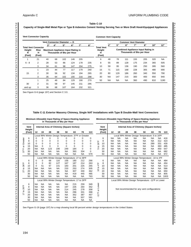
UNIFORM PLUMBING CODE
194
Appendix C
NFPANFPANFPANFPANFPANFPANFPANFPANFPANFPANFPANFPANFPANFPANFPANFPANFPANFPANFPANFPANFPANFPANFPA
NFPANFPANFPANFPANFPANFPANFPANFPANFPANFPANFPANFPANFPANFPANFPANFPANFPANFPANFPANFPANFPANFPANFPA
Vent Connector Capacity
Vent Connector Diameter — D3" 4" 5" 6" 7" 8"
Total Vent ConnectorHeight Rise Maximum Appliance Input Rating in
R H Thousands of Btu per Hour(Feet) (Feet)
1 21 40 68 102 146 205
6 - 8 2 28 53 86 124 178 235
3 34 61 98 147 204 275
1 23 44 77 117 179 240
15 2 30 56 92 134 194 265
3 35 64 102 155 216 298
1 25 49 84 129 190 270
30 2 31 58 97 145 211 295
and up 3 36 68 107 164 232 321
Common Vent Capacity
Common Vent Diameter4" 5" 6" 7" 8" 10" 12"
Total VentCombined Appliance Input Rating inHeight
Thousands of Btu per Hour H(Feet)
6 48 78 111 155 205 320 NA
8 55 89 128 175 234 365 505
10 59 95 136 190 250 395 560
15 71 115 168 228 305 480 690
20 80 129 186 260 340 550 790
30 NA 147 215 300 400 650 940
50 NA NA NA 360 490 810 1190
Minimum Allowable Input Rating of Space-Heating Appliancein Thousands of Btu per Hour
Vent Internal Area of Chimney (Square Inches)Height(Feet) 12 19 28 38 50 63 78 113
Local 99% Winter Design Temperature: 37ºF or Greater6 0 0 0 0 0 0 0 08 0 0 0 0 0 0 0 010 0 0 0 0 0 0 0 015 NA 0 0 0 0 0 0 020 NA NA 123 190 249 184 0 030 NA NA NA NA NA 393 334 050 NA NA NA NA NA NA NA 579
Local 99% Winter Design Temperature: 27 to 36ºF6 0 0 68 116 156 180 212 2668 0 0 82 127 167 187 214 26310 0 51 97 141 183 201 225 26515 NA NA NA NA 233 253 274 30520 NA NA NA NA NA 307 330 36230 NA NA NA NA NA 419 445 48550 NA NA NA NA NA NA NA 763
Local 99% Winter Design Temperature: 17 to 26ºF
6 NA NA NA NA NA 215 259 3498 NA NA NA NA 197 226 264 35210 NA NA NA NA 214 245 278 35815 NA NA NA NA NA 296 331 39820 NA NA NA NA NA 352 387 45730 NA NA NA NA NA NA 507 58150 NA NA NA NA NA NA NA NA
Minimum Allowable Input Rating of Space-Heating Appliancein Thousands of Btu per Hour
Vent Internal Area of Chimney (Square Inches)Height(Feet) 12 19 28 38 50 63 78 113
Local 99% Winter Design Temperature: 5 to 16ºF6 NA NA NA NA NA NA NA 4168 NA NA NA NA NA NA 312 423
10 NA NA NA NA NA 289 331 43015 NA NA NA NA NA NA 393 48520 NA NA NA NA NA NA 450 54730 NA NA NA NA NA NA NA 68250 NA NA NA NA NA NA NA 972
Local 99% Winter Design Temperature: -10 to 4ºF6 NA NA NA NA NA NA NA 4848 NA NA NA NA NA NA NA 494
10 NA NA NA NA NA NA NA 51315 NA NA NA NA NA NA NA 58620 NA NA NA NA NA NA NA 65030 NA NA NA NA NA NA NA 80550 NA NA NA NA NA NA NA 1003
Local 99% Winter Design Temperature: -11ºF or Lower
Not recommended for any vent configurations
37°F
or
Gre
ater
5 to
16°
F10
to
4°F
-11°
F o
r Lo
wer
27 t
o 36
°F17
to
26°F
See Figure G-6 (page 197) and Section C 3.0.
See Figure G-19 (page 197) for a map showing local 99 percent winter design temperatures in the United States.
Table C-11 Exterior Masonry Chimney, Single NAT Installations with Type B Double-Wall Vent Connectors
Table C-10Capacity of Single-Wall Metal Pipe or Type B Asbestos Cement Venting Serving Two or More Draft Hood-Equipped Appliances
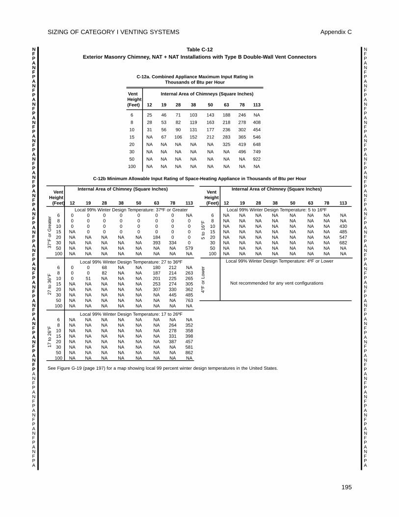
SIZING OF CATEGORY I VENTING SYSTEMS Appendix C
195
NFPANFPANFPANFPANFPANFPANFPANFPANFPANFPANFPANFPANFPANFPANFPANFPANFPANFPANFPANFPANFPANFPANFPA
NFPANFPANFPANFPANFPANFPANFPANFPANFPANFPANFPANFPANFPANFPANFPANFPANFPANFPANFPANFPANFPANFPANFPA
NFPANFPANFPANFPANFPANFPANFPANFPANFPANFPANFPANFPANFPANFPANFPANFPANFPANFP
C-12a. Combined Appliance Maximum Input Rating in Thousands of Btu per Hour
Vent Internal Area of Chimneys (Square Inches)Height(Feet) 12 19 28 38 50 63 78 113
6 25 46 71 103 143 188 246 NA
8 28 53 82 119 163 218 278 408
10 31 56 90 131 177 236 302 454
15 NA 67 106 152 212 283 365 546
20 NA NA NA NA NA 325 419 648
30 NA NA NA NA NA NA 496 749
50 NA NA NA NA NA NA NA 922
100 NA NA NA NA NA NA NA NA
Internal Area of Chimney (Square Inches)Vent
Height(Feet) 12 19 28 38 50 63 78 113
Local 99% Winter Design Temperature: 37ºF or Greater6 0 0 0 0 0 0 0 NA8 0 0 0 0 0 0 0 010 0 0 0 0 0 0 0 015 NA 0 0 0 0 0 0 020 NA NA NA NA NA 184 0 030 NA NA NA NA NA 393 334 050 NA NA NA NA NA NA NA 579100 NA NA NA NA NA NA NA NA
Local 99% Winter Design Temperature: 27 to 36ºF6 0 0 68 NA NA 180 212 NA8 0 0 82 NA NA 187 214 26310 0 51 NA NA NA 201 225 26515 NA NA NA NA NA 253 274 30520 NA NA NA NA NA 307 330 36230 NA NA NA NA NA NA 445 48550 NA NA NA NA NA NA NA 763100 NA NA NA NA NA NA NA NA
Local 99% Winter Design Temperature: 17 to 26ºF6 NA NA NA NA NA NA NA NA8 NA NA NA NA NA NA 264 35210 NA NA NA NA NA NA 278 35815 NA NA NA NA NA NA 331 39820 NA NA NA NA NA NA 387 45730 NA NA NA NA NA NA NA 58150 NA NA NA NA NA NA NA 862100 NA NA NA NA NA NA NA NA
Internal Area of Chimney (Square Inches)Vent
Height(Feet) 12 19 28 38 50 63 78 113
Local 99% Winter Design Temperature: 5 to 16ºF6 NA NA NA NA NA NA NA NA8 NA NA NA NA NA NA NA NA
10 NA NA NA NA NA NA NA 43015 NA NA NA NA NA NA NA 48520 NA NA NA NA NA NA NA 54730 NA NA NA NA NA NA NA 68250 NA NA NA NA NA NA NA NA
100 NA NA NA NA NA NA NA NA
Local 99% Winter Design Temperature: 4ºF or Lower
Not recommended for any vent configurations
37°F
or
Gre
ater
27 t
o 36
°F17
to
26°F
5 to
16°
F4°
F o
r Lo
wer
C-12b Minimum Allowable Input Rating of Space-Heating Appliance in Thousands of Btu per Hour
See Figure G-19 (page 197) for a map showing local 99 percent winter design temperatures in the United States.
Table C-12 Exterior Masonry Chimney, NAT + NAT Installations with Type B Double-Wall Vent Connectors
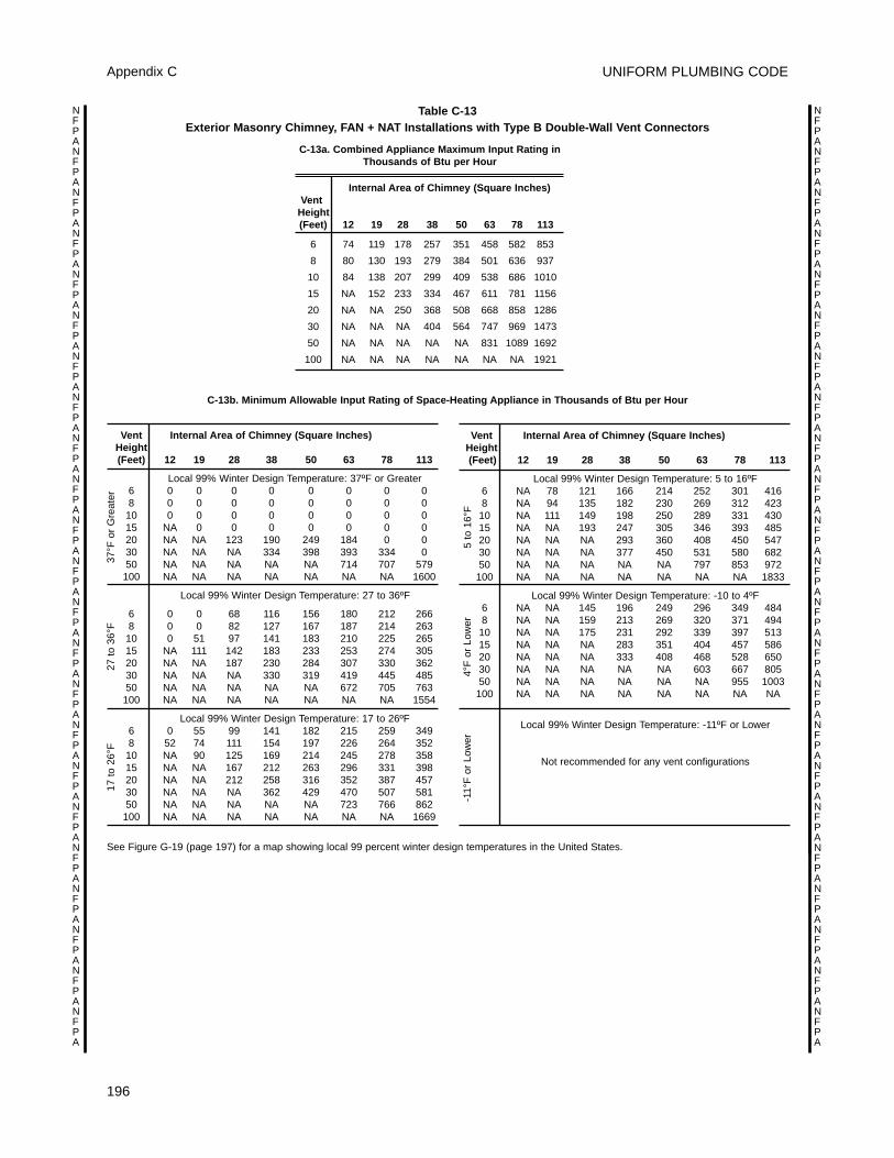
UNIFORM PLUMBING CODE
196
Appendix C
NFPANFPANFPANFPANFPANFPANFPANFPANFPANFPANFPANFPANFPANFPANFPANFPANFPANFPANFPANFPANFPANFPANFPA
NFPANFPANFPANFPANFPANFPANFPANFPANFPANFPANFPANFPANFPANFPANFPANFPANFPANFPANFPANFPANFPANFPANFPA
C-13a. Combined Appliance Maximum Input Rating inThousands of Btu per Hour
Internal Area of Chimney (Square Inches)Vent
Height(Feet) 12 19 28 38 50 63 78 113
6 74 119 178 257 351 458 582 853
8 80 130 193 279 384 501 636 937
10 84 138 207 299 409 538 686 1010
15 NA 152 233 334 467 611 781 1156
20 NA NA 250 368 508 668 858 1286
30 NA NA NA 404 564 747 969 1473
50 NA NA NA NA NA 831 1089 1692
100 NA NA NA NA NA NA NA 1921
Table C-13 Exterior Masonry Chimney, FAN + NAT Installations with Type B Double-Wall Vent Connectors
Vent Internal Area of Chimney (Square Inches)Height(Feet) 12 19 28 38 50 63 78 113
Local 99% Winter Design Temperature: 37ºF or Greater6 0 0 0 0 0 0 0 08 0 0 0 0 0 0 0 010 0 0 0 0 0 0 0 015 NA 0 0 0 0 0 0 020 NA NA 123 190 249 184 0 030 NA NA NA 334 398 393 334 050 NA NA NA NA NA 714 707 579100 NA NA NA NA NA NA NA 1600
Local 99% Winter Design Temperature: 27 to 36ºF
6 0 0 68 116 156 180 212 2668 0 0 82 127 167 187 214 26310 0 51 97 141 183 210 225 26515 NA 111 142 183 233 253 274 30520 NA NA 187 230 284 307 330 36230 NA NA NA 330 319 419 445 48550 NA NA NA NA NA 672 705 763100 NA NA NA NA NA NA NA 1554
Local 99% Winter Design Temperature: 17 to 26ºF6 0 55 99 141 182 215 259 3498 52 74 111 154 197 226 264 35210 NA 90 125 169 214 245 278 35815 NA NA 167 212 263 296 331 39820 NA NA 212 258 316 352 387 45730 NA NA NA 362 429 470 507 58150 NA NA NA NA NA 723 766 862100 NA NA NA NA NA NA NA 1669
Vent Internal Area of Chimney (Square Inches)Height(Feet) 12 19 28 38 50 63 78 113
Local 99% Winter Design Temperature: 5 to 16ºF6 NA 78 121 166 214 252 301 4168 NA 94 135 182 230 269 312 42310 NA 111 149 198 250 289 331 43015 NA NA 193 247 305 346 393 48520 NA NA NA 293 360 408 450 54730 NA NA NA 377 450 531 580 68250 NA NA NA NA NA 797 853 972
100 NA NA NA NA NA NA NA 1833
Local 99% Winter Design Temperature: -10 to 4ºF6 NA NA 145 196 249 296 349 4848 NA NA 159 213 269 320 371 49410 NA NA 175 231 292 339 397 51315 NA NA NA 283 351 404 457 58620 NA NA NA 333 408 468 528 65030 NA NA NA NA NA 603 667 80550 NA NA NA NA NA NA 955 1003
100 NA NA NA NA NA NA NA NA
Local 99% Winter Design Temperature: -11ºF or Lower
Not recommended for any vent configurations
C-13b. Minimum Allowable Input Rating of Space-Heating Appliance in Thousands of Btu per Hour
See Figure G-19 (page 197) for a map showing local 99 percent winter design temperatures in the United States.
37°F
or
Gre
ater
27 t
o 36
°F17
to
26°F
5 to
16°
F4°
F o
r Lo
wer
-11°
F o
r Lo
wer
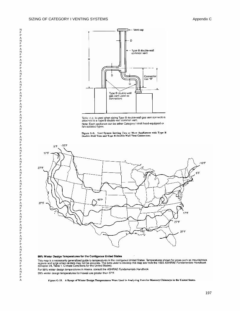
SIZING OF CATEGORY I VENTING SYSTEMS Appendix C
197
NFPANFPANFPANFPANFPANFPANFPANFPANFPANFPANFPANFPANFPANFPANFPANFPANFPANFPANFPANFPANFPANFPANFPA
C-6

UNIFORM PLUMBING CODE
198
Appendix C
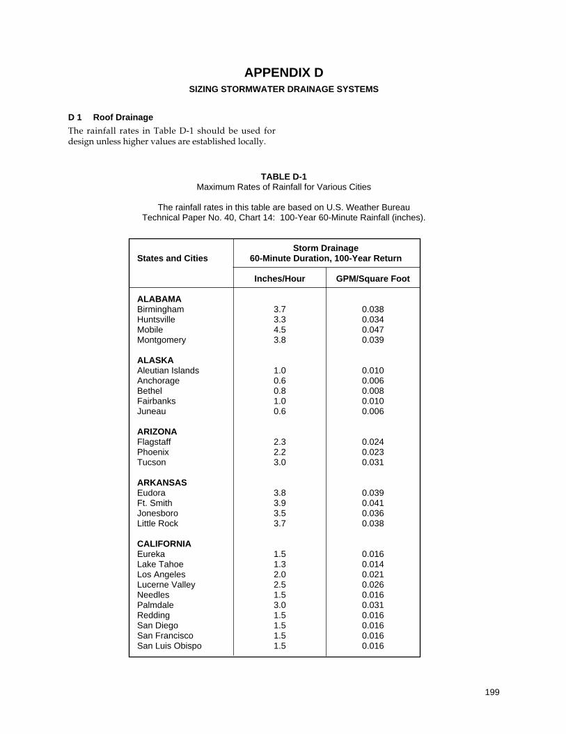
D 1 Roof Drainage
The rainfall rates in Table D-1 should be used fordesign unless higher values are established locally.
199
APPENDIX DSIZING STORMWATER DRAINAGE SYSTEMS
TABLE D-1Maximum Rates of Rainfall for Various Cities
The rainfall rates in this table are based on U.S. Weather Bureau Technical Paper No. 40, Chart 14: 100-Year 60-Minute Rainfall (inches).
Storm DrainageStates and Cities 60-Minute Duration, 100-Year Return
Inches/Hour GPM/Square Foot
ALABAMABirmingham 3.7 0.038Huntsville 3.3 0.034Mobile 4.5 0.047Montgomery 3.8 0.039
ALASKAAleutian Islands 1.0 0.010Anchorage 0.6 0.006Bethel 0.8 0.008Fairbanks 1.0 0.010Juneau 0.6 0.006
ARIZONAFlagstaff 2.3 0.024Phoenix 2.2 0.023Tucson 3.0 0.031
ARKANSASEudora 3.8 0.039Ft. Smith 3.9 0.041Jonesboro 3.5 0.036Little Rock 3.7 0.038
CALIFORNIAEureka 1.5 0.016Lake Tahoe 1.3 0.014Los Angeles 2.0 0.021Lucerne Valley 2.5 0.026Needles 1.5 0.016Palmdale 3.0 0.031Redding 1.5 0.016San Diego 1.5 0.016San Francisco 1.5 0.016San Luis Obispo 1.5 0.016
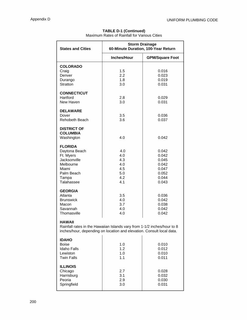
UNIFORM PLUMBING CODE
200
Appendix D
TABLE D-1 (Continued)Maximum Rates of Rainfall for Various Cities
Storm DrainageStates and Cities 60-Minute Duration, 100-Year Return
Inches/Hour GPM/Square Foot
COLORADOCraig 1.5 0.016Denver 2.2 0.023Durango 1.8 0.019Stratton 3.0 0.031
CONNECTICUTHartford 2.8 0.029New Haven 3.0 0.031
DELAWAREDover 3.5 0.036Rehobeth Beach 3.6 0.037
DISTRICT OF COLUMBIAWashington 4.0 0.042
FLORIDADaytona Beach 4.0 0.042Ft. Myers 4.0 0.042Jacksonville 4.3 0.045Melbourne 4.0 0.042Miami 4.5 0.047Palm Beach 5.0 0.052Tampa 4.2 0.044Talahassee 4.1 0.043
GEORGIAAtlanta 3.5 0.036Brunswick 4.0 0.042Macon 3.7 0.038Savannah 4.0 0.042Thomasville 4.0 0.042
HAWAIIRainfall rates in the Hawaiian Islands vary from 1-1/2 inches/hour to 8inches/hour, depending on location and elevation. Consult local data.
IDAHOBoise 1.0 0.010Idaho Falls 1.2 0.012Lewiston 1.0 0.010Twin Falls 1.1 0.011
ILLINOISChicago 2.7 0.028Harrisburg 3.1 0.032Peoria 2.9 0.030Springfield 3.0 0.031
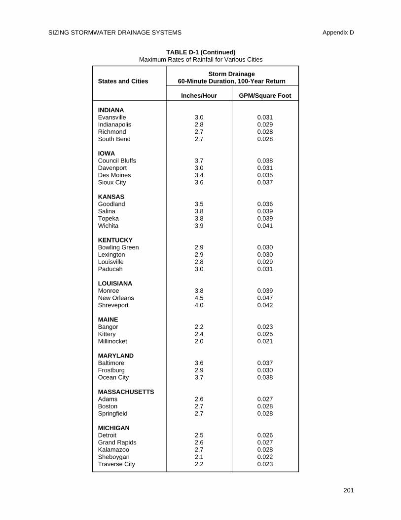
SIZING STORMWATER DRAINAGE SYSTEMS Appendix D
201
TABLE D-1 (Continued)Maximum Rates of Rainfall for Various Cities
Storm DrainageStates and Cities 60-Minute Duration, 100-Year Return
Inches/Hour GPM/Square Foot
INDIANAEvansville 3.0 0.031Indianapolis 2.8 0.029Richmond 2.7 0.028South Bend 2.7 0.028
IOWACouncil Bluffs 3.7 0.038Davenport 3.0 0.031Des Moines 3.4 0.035Sioux City 3.6 0.037
KANSASGoodland 3.5 0.036Salina 3.8 0.039Topeka 3.8 0.039Wichita 3.9 0.041
KENTUCKYBowling Green 2.9 0.030Lexington 2.9 0.030Louisville 2.8 0.029Paducah 3.0 0.031
LOUISIANAMonroe 3.8 0.039New Orleans 4.5 0.047Shreveport 4.0 0.042
MAINEBangor 2.2 0.023Kittery 2.4 0.025Millinocket 2.0 0.021
MARYLANDBaltimore 3.6 0.037Frostburg 2.9 0.030Ocean City 3.7 0.038
MASSACHUSETTSAdams 2.6 0.027Boston 2.7 0.028Springfield 2.7 0.028
MICHIGANDetroit 2.5 0.026Grand Rapids 2.6 0.027Kalamazoo 2.7 0.028Sheboygan 2.1 0.022Traverse City 2.2 0.023
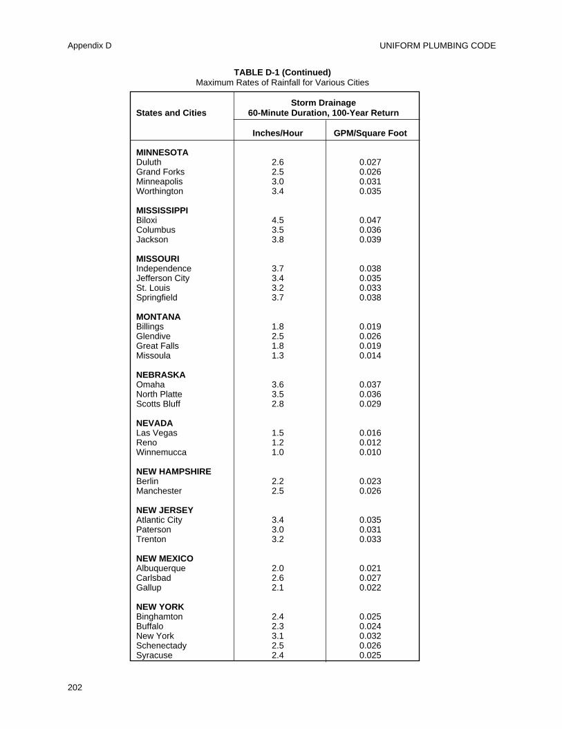
UNIFORM PLUMBING CODE
202
Appendix D
TABLE D-1 (Continued)Maximum Rates of Rainfall for Various Cities
Storm DrainageStates and Cities 60-Minute Duration, 100-Year Return
Inches/Hour GPM/Square Foot
MINNESOTADuluth 2.6 0.027Grand Forks 2.5 0.026Minneapolis 3.0 0.031Worthington 3.4 0.035
MISSISSIPPIBiloxi 4.5 0.047Columbus 3.5 0.036Jackson 3.8 0.039
MISSOURIIndependence 3.7 0.038Jefferson City 3.4 0.035St. Louis 3.2 0.033Springfield 3.7 0.038
MONTANABillings 1.8 0.019Glendive 2.5 0.026Great Falls 1.8 0.019Missoula 1.3 0.014
NEBRASKAOmaha 3.6 0.037North Platte 3.5 0.036Scotts Bluff 2.8 0.029
NEVADALas Vegas 1.5 0.016Reno 1.2 0.012Winnemucca 1.0 0.010
NEW HAMPSHIREBerlin 2.2 0.023Manchester 2.5 0.026
NEW JERSEYAtlantic City 3.4 0.035Paterson 3.0 0.031Trenton 3.2 0.033
NEW MEXICOAlbuquerque 2.0 0.021Carlsbad 2.6 0.027Gallup 2.1 0.022
NEW YORKBinghamton 2.4 0.025Buffalo 2.3 0.024New York 3.1 0.032Schenectady 2.5 0.026Syracuse 2.4 0.025
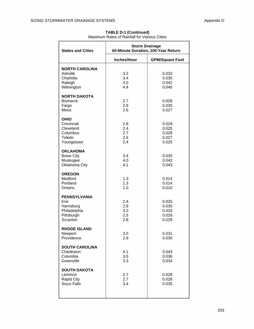
SIZING STORMWATER DRAINAGE SYSTEMS Appendix D
203
TABLE D-1 (Continued)Maximum Rates of Rainfall for Various Cities
Storm DrainageStates and Cities 60-Minute Duration, 100-Year Return
Inches/Hour GPM/Square Foot
NORTH CAROLINAAshville 3.2 0.033Charlotte 3.4 0.035Raleigh 4.0 0.042Wilmington 4.4 0.046
NORTH DAKOTABismarck 2.7 0.028Fargo 2.9 0.030Minot 2.6 0.027
OHIOCincinnati 2.8 0.029Cleveland 2.4 0.025Columbus 2.7 0.028Toledo 2.6 0.027Youngstown 2.4 0.025
OKLAHOMABoise City 3.4 0.035Muskogee 4.0 0.042Oklahoma City 4.1 0.043
OREGONMedford 1.3 0.014Portland 1.3 0.014Ontario 1.0 0.010
PENNSYLVANIAErie 2.4 0.025Harrisburg 2.9 0.030Philadelphia 3.2 0.033Pittsburgh 2.5 0.026Scranton 2.8 0.029
RHODE ISLANDNewport 3.0 0.031Providence 2.9 0.030
SOUTH CAROLINACharleston 4.1 0.043Columbia 3.5 0.036Greenville 3.3 0.034
SOUTH DAKOTALemmon 2.7 0.028Rapid City 2.7 0.028Sioux Falls 3.4 0.035
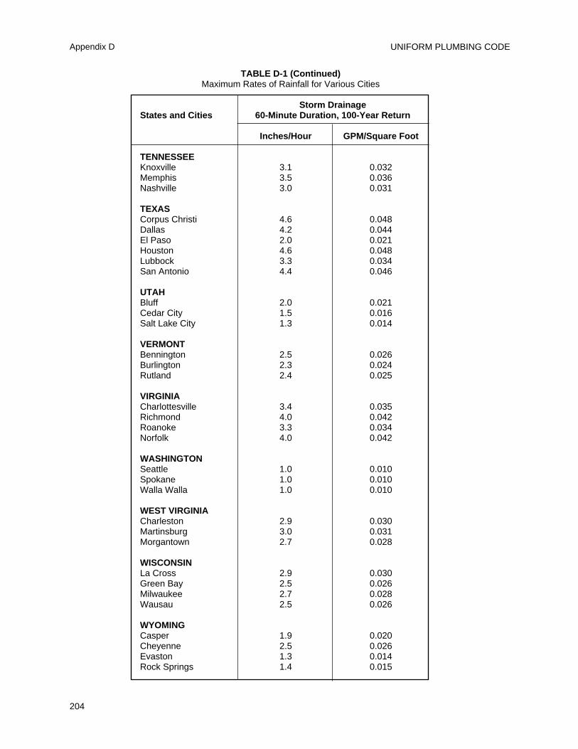
UNIFORM PLUMBING CODE
204
Appendix D
TABLE D-1 (Continued)Maximum Rates of Rainfall for Various Cities
Storm DrainageStates and Cities 60-Minute Duration, 100-Year Return
Inches/Hour GPM/Square Foot
TENNESSEEKnoxville 3.1 0.032Memphis 3.5 0.036Nashville 3.0 0.031
TEXASCorpus Christi 4.6 0.048Dallas 4.2 0.044El Paso 2.0 0.021Houston 4.6 0.048Lubbock 3.3 0.034San Antonio 4.4 0.046
UTAHBluff 2.0 0.021Cedar City 1.5 0.016Salt Lake City 1.3 0.014
VERMONTBennington 2.5 0.026Burlington 2.3 0.024Rutland 2.4 0.025
VIRGINIACharlottesville 3.4 0.035Richmond 4.0 0.042Roanoke 3.3 0.034Norfolk 4.0 0.042
WASHINGTONSeattle 1.0 0.010Spokane 1.0 0.010Walla Walla 1.0 0.010
WEST VIRGINIACharleston 2.9 0.030Martinsburg 3.0 0.031Morgantown 2.7 0.028
WISCONSINLa Cross 2.9 0.030Green Bay 2.5 0.026Milwaukee 2.7 0.028Wausau 2.5 0.026
WYOMINGCasper 1.9 0.020Cheyenne 2.5 0.026Evaston 1.3 0.014Rock Springs 1.4 0.015
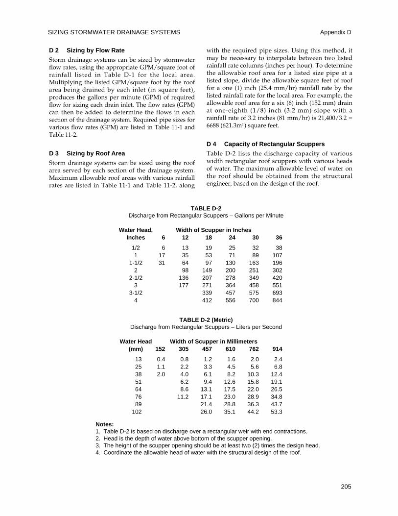
SIZING STORMWATER DRAINAGE SYSTEMS Appendix D
205
D 2 Sizing by Flow Rate
Storm drainage systems can be sized by stormwaterflow rates, using the appropriate GPM/square foot ofrainfall listed in Table D-1 for the local area.Multiplying the listed GPM/square foot by the roofarea being drained by each inlet (in square feet),produces the gallons per minute (GPM) of requiredflow for sizing each drain inlet. The flow rates (GPM)can then be added to determine the flows in eachsection of the drainage system. Required pipe sizes forvarious flow rates (GPM) are listed in Table 11-1 andTable 11-2.
D 3 Sizing by Roof Area
Storm drainage systems can be sized using the roofarea served by each section of the drainage system.Maximum allowable roof areas with various rainfallrates are listed in Table 11-1 and Table 11-2, along
with the required pipe sizes. Using this method, itmay be necessary to interpolate between two listedrainfall rate columns (inches per hour). To determinethe allowable roof area for a listed size pipe at alisted slope, divide the allowable square feet of rooffor a one (1) inch (25.4 mm/hr) rainfall rate by thelisted rainfall rate for the local area. For example, theallowable roof area for a six (6) inch (152 mm) drainat one-eighth (1/8) inch (3.2 mm) slope with arainfall rate of 3.2 inches (81 mm/hr) is 21,400/3.2 =6688 (621.3m2 ) square feet.
D 4 Capacity of Rectangular Scuppers
Table D-2 lists the discharge capacity of variouswidth rectangular roof scuppers with various headsof water. The maximum allowable level of water onthe roof should be obtained from the structuralengineer, based on the design of the roof.
TABLE D-2Discharge from Rectangular Scuppers – Gallons per Minute
Water Head, Width of Scupper in InchesInches 6 12 18 24 30 36
1/2 6 13 19 25 32 381 17 35 53 71 89 107
1-1/2 31 64 97 130 163 1962 98 149 200 251 302
2-1/2 136 207 278 349 4203 177 271 364 458 551
3-1/2 339 457 575 6934 412 556 700 844
TABLE D-2 (Metric)Discharge from Rectangular Scuppers – Liters per Second
Water Head Width of Scupper in Millimeters(mm) 152 305 457 610 762 914
13 0.4 0.8 1.2 1.6 2.0 2.425 1.1 2.2 3.3 4.5 5.6 6.838 2.0 4.0 6.1 8.2 10.3 12.451 6.2 9.4 12.6 15.8 19.164 8.6 13.1 17.5 22.0 26.576 11.2 17.1 23.0 28.9 34.889 21.4 28.8 36.3 43.7
102 26.0 35.1 44.2 53.3
Notes:1. Table D-2 is based on discharge over a rectangular weir with end contractions.2. Head is the depth of water above bottom of the scupper opening.3. The height of the scupper opening should be at least two (2) times the design head.4. Coordinate the allowable head of water with the structural design of the roof.

UNIFORM PLUMBING CODE
206
207
Part A
Manufactured/Mobile Home (M/H) Park Definitions and General Requirements
E 1 Manufactured/Mobile Home
A structure, transportable in one (1) or more sections,which in the traveling mode, is eight (8) body feet(2438 mm) or more in width and forty (40) body feet(12192 mm) or more in length, or when erected onsite, is three hundred twenty (320) or more squarefeet (29.7 m2), and which is built on a permanentchassis, and designed to be used as a dwelling withor without a permanent foundation, when connectedto the required utilities, and includes the plumbing,heating, air conditioning, and electrical systemscontained therein. For further clarification ofdefinition, see Federal Regulation 24 CFR.
E 1.1 Manufactured/Mobile Home AccessoryBuilding or Structure – A building or structurewhich is an addition to or supplements the facilitiesprovided to a M/H. It is not a self-contained,separate, habitable building or structure. Examplesare awnings, cabanas, ramadas, storage structures,carports, fences, windbreaks, or porches.
E 2 Manufactured/Mobile Home Lot – A portion ofa M/H park designed for the accommodation of oneM/H and its accessory buildings or structures for theexclusive use of the occupants.
E 3 Manufactured/Mobile Home Park – A parcel(or contiguous parcels) of land which has been sodesignated and improved that it contains two (2) ormore M/H lots available to the general public for theplacement thereon of M/H for occupancy.
General
E 4 The M/H park plumbing and drainage systemsshall be designed and installed in accordance withthe requirements of this appendix and therequirements of this Code.
E 5 Before any plumbing or sewage disposalfacilities are installed or altered in any M/H park,duplicate plans and specifications shall be filed andproper permits obtained from the department ordepartments having jurisdiction. Plans shall show indetail:
(a) Plot plan of the park drawn to scale, indicatingelevations, property lines, driveways, existing orproposed buildings and the sizes of M/H lots.
(b) Complete specification and piping layout ofproposed plumbing systems or alteration.
(c) Complete specification and layout of proposedsewage disposal system or alteration.
(d) Plans and specifications submitted to theenforcement agency shall be of sufficient clarity toindicate the nature and extent of the work proposedand show in detail that such work will conform tothe provisions of this Code.
Part B
Manufactured/Mobile Home Park DrainageSystem Construction
E 6 Drainage Systems
A drainage system shall be provided in all M/Hparks for conveying and disposing of all sewage.Wherever feasible, connection shall be made to apublic system. All new improvements shall bedesigned, constructed and maintained in accordancewith applicable laws and regulations. Where thedrainage lines of the M/H park are not connected toa public sewer, all proposed sewage disposalfacilities shall be approved by the Authority HavingJurisdiction prior to construction.
E 7 Material
Pipe and fittings installed underground in M/Hpark drainage systems shall be of material approvedfor the purpose. M/H lot drainage inlets andextensions to grade shall be of material approved forunderground use within a building.
E 8 Drainage (Sewage) Lines
All drainage (sewage) collection lines shall be locatedin trenches of sufficient depth to be free of breakagefrom traffic or other movements and shall beseparated from the park water supply system asspecified in this Code. Drainage (sewage) lines shallhave a minimum size and slope as specified inTables E-1 and E-2.
E 9 M/H Lot Drainage Inlet and Lateral
(a) Size. Each lot shall be provided with a drainageinlet not less than three (3) inches (76 mm) indiameter.
(b) The lateral line from the inlet to the sewagedrain line shall slope at least one-fourth (1/4) inchper foot (20.9 mm/m). All joints shall be watertight.
(c) All materials used for drainage connections
APPENDIX E
MANUFACTURED/MOBILE HOME PARKS AND RECREATIONAL VEHICLE PARKS
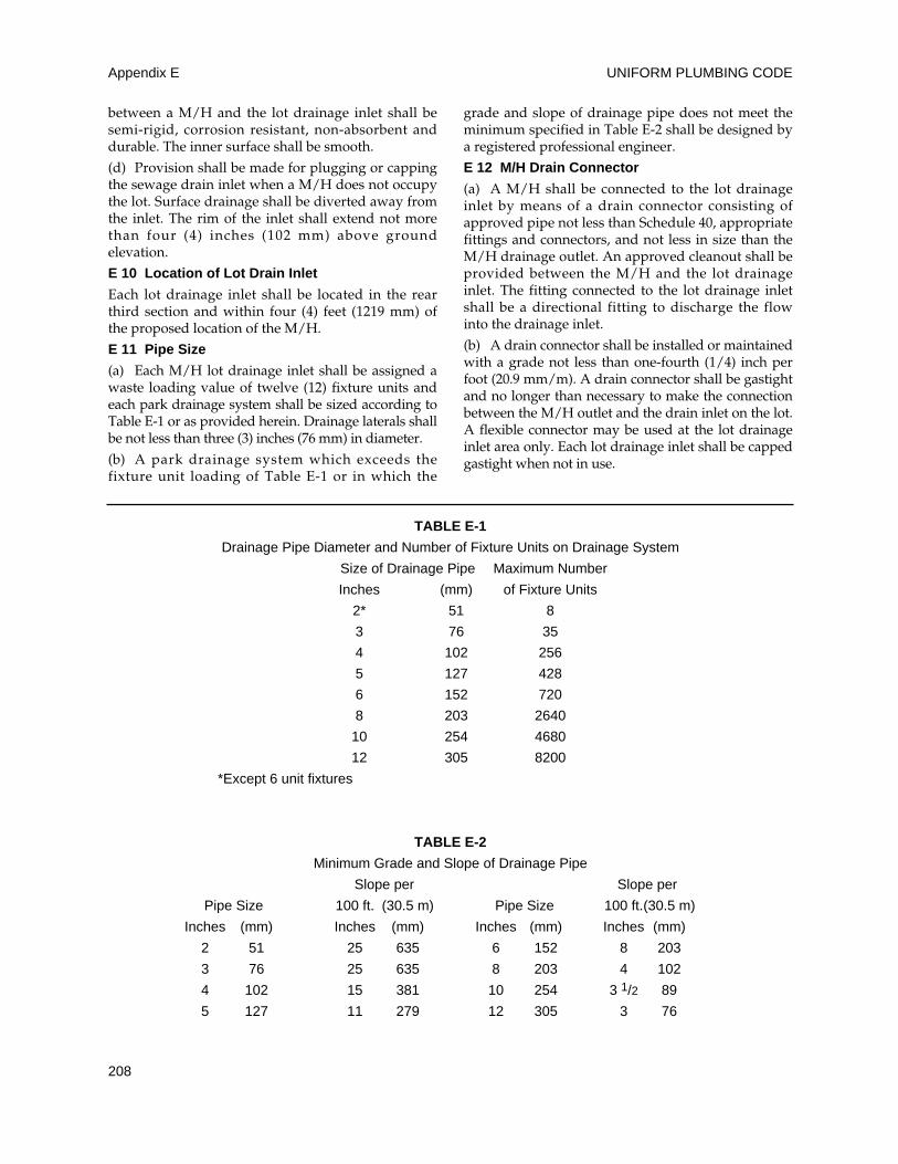
UNIFORM PLUMBING CODEAppendix E
208
between a M/H and the lot drainage inlet shall besemi-rigid, corrosion resistant, non-absorbent anddurable. The inner surface shall be smooth.
(d) Provision shall be made for plugging or cappingthe sewage drain inlet when a M/H does not occupythe lot. Surface drainage shall be diverted away fromthe inlet. The rim of the inlet shall extend not morethan four (4) inches (102 mm) above groundelevation.
E 10 Location of Lot Drain Inlet
Each lot drainage inlet shall be located in the rearthird section and within four (4) feet (1219 mm) ofthe proposed location of the M/H.
E 11 Pipe Size
(a) Each M/H lot drainage inlet shall be assigned awaste loading value of twelve (12) fixture units andeach park drainage system shall be sized according toTable E-1 or as provided herein. Drainage laterals shallbe not less than three (3) inches (76 mm) in diameter.
(b) A park drainage system which exceeds thefixture unit loading of Table E-1 or in which the
grade and slope of drainage pipe does not meet theminimum specified in Table E-2 shall be designed bya registered professional engineer.
E 12 M/H Drain Connector
(a) A M/H shall be connected to the lot drainageinlet by means of a drain connector consisting ofapproved pipe not less than Schedule 40, appropriatefittings and connectors, and not less in size than theM/H drainage outlet. An approved cleanout shall beprovided between the M/H and the lot drainageinlet. The fitting connected to the lot drainage inletshall be a directional fitting to discharge the flowinto the drainage inlet.
(b) A drain connector shall be installed or maintainedwith a grade not less than one-fourth (1/4) inch perfoot (20.9 mm/m). A drain connector shall be gastightand no longer than necessary to make the connectionbetween the M/H outlet and the drain inlet on the lot.A flexible connector may be used at the lot drainageinlet area only. Each lot drainage inlet shall be cappedgastight when not in use.
TABLE E-1
Drainage Pipe Diameter and Number of Fixture Units on Drainage System
Size of Drainage Pipe Maximum Number
Inches (mm) of Fixture Units
2* 51 8
3 76 35
4 102 256
5 127 428
6 152 720
8 203 2640
10 254 4680
12 305 8200
*Except 6 unit fixtures
TABLE E-2
Minimum Grade and Slope of Drainage Pipe
Slope per Slope per
Pipe Size 100 ft. (30.5 m) Pipe Size 100 ft.(30.5 m)
Inches (mm) Inches (mm) Inches (mm) Inches (mm)
2 51 25 635 6 152 8 203
3 76 25 635 8 203 4 102
4 102 15 381 10 254 3 1/2 89
5 127 11 279 12 305 3 76
MANUFACTURED/MH PARKS AND RV PARKS Appendix E
209
Part C
M/H Park Water Supply
E 13 General Requirements
An accessible and adequate supply of potable watershall be provided in each M/H park. Where a publicsupply of water of satisfactory quantity, quality andpressure is available at or within the boundary of thepark site, connection shall be made thereto and itssupply used exclusively. When a satisfactory publicwater supply is not available, a private water supplysystem shall be developed and used as approved bythe Authority Having Jurisdiction.
E 14 Lot Service Outlet Size
Each M/H lot shall be provided with a water serviceoutlet delivering potable water. The water serviceoutlet riser shall be not less than three-fourths (3/4)inch (19.1 mm) nominal pipe size and capable ofdelivering twelve (12) fixture units.
E 15 Location of Water Service
Each lot water service outlet shall be located in therear third section and within four (4) feet (1219 mm)of the proposed location of the M/H.
E 16 Pressure
Each M/H park water distribution system shall be sodesigned and maintained as to provide a pressure ofnot less than twenty (20) pounds per square inch(138 kPa) at each M/H lot at maximum operatingconditions.
E 17 Water Distribution Piping
Park water distribution systems shall be designed todeliver a minimum of twelve (12) fixture units ofwater to each lot and installed with materials as setforth in Chapter 6 and/or Appendix A of this Code.
E 18 Shutoff Valve
A separate water shutoff valve shall be installed ineach water service outlet at each M/H lot. Where alisted backflow protective device is installed, theservice shutoff shall be located on the supply side ofsuch device.
E 19 Backflow Preventer
Whenever a condition exists in the plumbing of aM/H that may create a cross connection, a listedbackflow preventer shall be installed in the waterservice line to the M/H at or near the water serviceoutlet. When a hose bibb or outlet is installed on thesupply outlet riser in addition to the serviceconnector, a listed backflow preventer shall beinstalled on each additional outlet.
E 20 Pressure Relief Valve
Whenever it is required to install a backflowpreventer at the M/H lot service outlet, a listedpressure relief valve shall be installed in the water
service line on the discharge side of the backflowpreventer. Pressure relief valves shall be set torelease at a pressure not to exceed one hundred fifty(150) pounds per square inch (1034 kPa). Pressurerelief valves shall discharge toward the ground.Backflow preventers and pressure relief valves shallbe at least twelve (12) inches (305 mm) above theground.
E 21 Mechanical Protection
All park water service outlets, backflow preventersand pressure relief valves shall be protected fromdamage by vehicles or other causes. Such protectionmay consist of posts, fencing, or other permanentbarriers.
E 22 M/H Water Connector
A M/H shall be connected to the park water serviceoutlet by a flexible connector, such as copper tubingor other approved material, not less than three quarter(3/4) inch nominal (19.1 mm) interior diameter.
E 23 Water Conditioning Equipment
(a) Permit Required. A permit shall be obtainedfrom the Authority Having Jurisdiction prior toinstalling any water conditioning equipment on aM/H lot. Approval of the park operator is requiredon all applications for a permit to install suchequipment. If the water conditioning equipment is ofthe regenerating type, and the park drainage systemdischarges into public sewer, approval of thesanitary district or agency having jurisdiction overthe public sewer is required.
(b) Approval. Regenerating water conditioningequipment shall be listed and labeled by anapproved listing agency.
(c) Installation. Regenerating units shall dischargethe effluent of regeneration into a trap not less thanone and one-half (1-1/2) inches (38 mm) in diameterconnected to the M/H park drainage system. Anapproved air gap shall be installed on the dischargeline a minimum of twelve (12) inches (305 mm)above the ground.
E 24 Testing
Installations shall be tested and inspected asrequired by Chapter 3 of this Code.
Part D
M/H Park Fuel Gas Equipment and Installation
E 25 General
Except as otherwise permitted or required by thisappendix, all fuel gas equipment and installations inM/H parks shall comply with the provisions of thisCode. The provisions of this appendix do not applyto M/H gas piping and equipment.
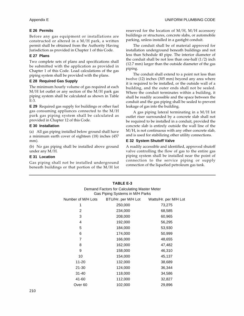
UNIFORM PLUMBING CODEAppendix E
210
E 26 Permits
Before any gas equipment or installations areconstructed or altered in a M/H park, a writtenpermit shall be obtained from the Authority HavingJurisdiction as provided in Chapter 1 of this Code.
E 27 Plans
Two complete sets of plans and specifications shallbe submitted with the application as provided inChapter 1 of this Code. Load calculations of the gaspiping system shall be provided with the plans.
E 28 Required Gas Supply
The minimum hourly volume of gas required at eachM/H lot outlet or any section of the M/H park gaspiping system shall be calculated as shown in TableE-3.
E 29 Required gas supply for buildings or other fuelgas consuming appliances connected to the M/Hpark gas piping system shall be calculated asprovided in Chapter 12 of this Code.
E 30 Installation
(a) All gas piping installed below ground shall havea minimum earth cover of eighteen (18) inches (457mm).
(b) No gas piping shall be installed above groundunder any M/H.
E 31 Location
Gas piping shall not be installed undergroundbeneath buildings or that portion of the M/H lot
reserved for the location of M/H, M/H accessorybuildings or structures, concrete slabs, or automobileparking, unless installed in a gastight conduit.
The conduit shall be of material approved forinstallation underground beneath buildings and notless than Schedule 40 pipe. The interior diameter ofthe conduit shall be not less than one-half (1/2) inch(12.7 mm) larger than the outside diameter of the gaspiping.
The conduit shall extend to a point not less thantwelve (12) inches (305 mm) beyond any area whereit is required to be installed, or the outside wall of abuilding, and the outer ends shall not be sealed.Where the conduit terminates within a building, itshall be readily accessible and the space between theconduit and the gas piping shall be sealed to preventleakage of gas into the building.
A gas piping lateral terminating in a M/H lotoutlet riser surrounded by a concrete slab shall notbe required to be installed in a conduit, provided theconcrete slab is entirely outside the wall line of theM/H, is not continuous with any other concrete slab,and is used for stabilizing other utility connections.
E 32 System Shutoff Valve
A readily accessible and identified, approved shutoffvalve controlling the flow of gas to the entire gaspiping system shall be installed near the point ofconnection to the service piping or supplyconnection of the liquefied petroleum gas tank.
TABLE E-3
Demand Factors for Calculating Master Meter Gas Piping Systems in M/H Parks
Number of M/H Lots BTU/Hr. per M/H Lot Watts/Hr. per M/H Lot
1 250,000 73,275
2 234,000 68,585
3 208,000 60,965
4 192,000 56,295
5 184,000 53,930
6 174,000 50,999
7 166,000 48,655
8 162,000 47,482
9 158,000 46,310
10 154,000 45,137
11-20 132,000 38,689
21-30 124,000 36,344
31-40 118,000 34,586
41-60 112,000 32,827
Over 60 102,000 29,896
MANUFACTURED/MH PARKS AND RV PARKS Appendix E
211
E 33 M/H Lot Shutoff Valve
Each M/H lot shall have an approved gas shutoffvalve installed upstream of the M/H lot gas outletand located on the outlet riser at a height of not lessthan four (4) inches (102 mm) above grade. Suchvalve shall not be located under any M/H.Whenever the M/H lot outlet is not in use, the outletshall be equipped with an approved cap or plug toprevent accidental discharge of gas.
E 34 Lot Gas Outlet
(a) Each M/H lot piped for gas shall be providedwith an individual outlet riser at the M/H lot.
(b) The M/H lot gas outlet shall terminate with theservice connection in the rear third section andwithin four (4) feet (1219 mm) of the proposedlocation of the M/H.
E 35 Gas Connector
Each M/H shall be connected to the lot outlet by anapproved or listed gas connector, a maximum of six(6) feet (1829 mm) in length. Approved pipe fittingsmay be used between the flexible connector and thelot gas outlet when the distance between the lot gasoutlet and the gas service connection exceeds thatrequired to make a safe installation with only anapproved or listed gas connector. Gas connectorsshall be of a size to adequately supply the totaldemand of the connected M/H.
E 36 Mechanical Protection
All gas outlet risers, regulators, meters, valves orother exposed equipment shall be protected frommechanical damage. Such protection may consist ofposts, fencing, or other permanent barriers.
Atmospherically controlled regulators shall beinstalled in such a manner that moisture cannot enterthe regulator vent and accumulate above thediaphragm. Where the regulator vent may beobstructed due to snow and icing conditions, shields,hoods, or other suitable devices shall be provided toguard against closing the vent opening.
E 37 Gas Meters
(a) Meters shall not be installed in unvented orinaccessible locations, or closer than three (3) feet(914 mm) from sources of ignition.
(b) When meters are installed, they shall not dependon the gas outlet riser for support, but shall beadequately supported by a post or bracket placed ona firm footing, or other means providing equivalentsupport.
E 38 Gas Piping Size
(a) Natural Gas. The size of each section of naturalgas piping systems shall be determined as specifiedin Chapter 12 of this Code or other standard
engineering methods acceptable to the AuthorityHaving Jurisdiction.
(b) Liquefied Petroleum Gas. The size of eachsection of liquefied petroleum gas piping systemsmay be determined by Chapter 12 of this Code orother standard engineering methods acceptable tothe Authority Having Jurisdiction.
E 39 Maintenance
The M/H park operator shall be responsible formaintaining all gas piping installations andequipment in good working condition.
E 40 Authority to Disconnect
The Administrative Authority or the serving gassupplier is hereby authorized to disconnect any gaspiping or appliance, or both, which shall be foundnot to conform to the requirements of this Code orwhich may be found defective and in such conditionas to endanger life or property.
Where such disconnection has been made, anotice shall be attached to such gas piping orappliance, or both, which shall state the same hasbeen disconnected, together with the reasonstherefor.
E 41 Inspections and Tests
Inspections and tests shall be made in accordancewith Chapters 1 and 12.
Part E
Recreational Vehicle Parks Definitions andGeneral Requirements
E 42 Recreational Vehicle – A vehicular type unitprimarily designed as temporary living quarters forrecreational, camping, travel or seasonal use, thateither has its own motive power, or is mounted on ortowed by another vehicle. The basic entities are:camping trailer, fifth wheel trailer, motor home, parktrailer, travel trailer, and truck camper.
E 43 Recreational Vehicle Park – A plot of landupon which two (2) or more recreational vehicle sitesare located, established or maintained for occupancyby recreational vehicles of the general public astemporary living quarters for recreation or vacationpurpose.
E 44 Recreational Vehicle Site – A plot of groundwithin a recreational vehicle park intended for theaccommodation of a recreational vehicle, a tent, orother individual camping unit on a temporary basis.
E 45 General. All plumbing shall be installed inaccordance with the plumbing codes of theAuthority Having Jurisdiction and with thisappendix.
UNIFORM PLUMBING CODEAppendix E
212
Part F
Recreational Vehicle Park Toilet and ShowerFacilities
E 46 Toilets and urinals shall be provided at one (1)or more locations in every recreational vehicle park.They shall be convenient of access and shall belocated within a five hundred (500) foot (152.4 m)radius from any recreational vehicle site notprovided with an individual sewer connection.E 47 Facilities for males and females shall beappropriately marked.E 48 A minimum of one (1) toilet shall be providedfor each sex up to the first twenty-five (25) sites. Foreach additional twenty-five (25) sites not providedwith sewer connections, an additional toilet shall beprovided.E 49 The interior finish of walls shall be moisture-resistant to a height of four (4) feet (1219 mm) tofacilitate washing and cleaning.E 50 The floors shall be constructed of materialimpervious to water and shall be easily cleanable.Any toilet building having water-flush toilets shallbe provided with a floor drain in the toilet room.This drain shall be provided with means to protectthe trap seal as required by this Code.E 51 If water-flush toilets are provided, an equalnumber of lavatories shall be provided for up to six(6) toilets. One additional lavatory shall be providedfor each two (2) toilets when more than six (6) toiletsare required. Each lavatory basin shall have a pipedsupply of potable water and shall drain into thedrainage system.E 52 If separate facilities are provided for men andwomen, urinals shall be acceptable for no more thanone-third (1/3) of the toilets required in the men’sfacilities, except that one (1) urinal may be used toreplace a toilet in a minimum park. Only individualstall or wall hung types of urinals shall be installed.Floor type trough units shall be prohibited.E 53 Toilets shall be of an approved, elongated bowltype and shall be provided with seats with openfronts.E 54 Each toilet shall be in a separate compartmentand be provided with a door with a latch for privacyand a holder or dispenser for toilet paper. Dividingwalls or partitions shall be at least five (5) feet (1524mm) high and shall be separated from the floor by aspace not greater than twelve (12) inches (305 mm).E 55 Toilet compartments shall not be less thanthirty (30) inches (762 mm) in width, (no toilet shallbe set closer than fifteen (15) inches (381 mm) fromits center to a side wall) and there shall be not lessthan thirty (30) inches (762 mm) of clear space infront of each toilet.
E 56 Each toilet room for women shall be providedwith a receptacle for sanitary napkins. The receptacleshall be of durable impervious and readily cleanablematerial, and shall be provided with a lid.
E 57 Each shower, if provided, shall have a floor areaof thirty-six (36) inches by thirty-six (36) inches (914mm x 914 mm) and shall be capable of encompassinga thirty (30) inch (762 mm) diameter circle and shall beof the individual type, and each shower area shall bevisually screened from view, with a minimum floorarea of thirty-six (36) by thirty-six (36) inches (914 mmx 914 mm) per shower and shall be provided withindividual dressing areas screened from view andshall contain a minimum of one (1) clothing hook andstool (or equivalent bench area).
E 58 Each shower area shall be designed tominimize the flow of water into the dressing areaand shall be connected to the drainage system bymeans of a properly vented and trapped inlet. Eachsuch area shall have a impervious, skid resistantsurface, wooden racks (duck boards) over showerfloors shall be prohibited.
E 59 Every toilet building shall have a minimumceiling height of seven (7) feet (2134 mm) and unlessartificial light is provided, a window or skylight,area equal to at least ten (10) percent of the floorarea, shall be provided.
All doors to the exterior shall open outward, beself-closing, and shall be visually screened by meansof a vestibule or wall to prevent direct view of theinterior when the exterior doors are open. Suchscreening shall not be required on single toilet units.
E 60 Every toilet room shall have permanent non-closable, screened opening(s), having a total area notless than five (5) percent of the floor area, openingdirectly to the exterior in order to provide properventilation. Listed exhaust fan(s), vented to theexterior ,the rating of which in cubic feet per minuteis at least twenty-five (25) percent of the total volumeof the room(s) served, shall be considered as meetingthe requirements of this subsection. All openablewindows and vents to the outside shall be providedwith fly proof screens of not less than numbersixteen (16) mesh.
Part G
Recreational Vehicle Park Potable Water Supplyand Distribution
E 61 Quality
The supply or supplies of water shall comply with theappropriate potable water standards of the state or localhealth authority or, in the absence thereof, with theDrinking Water Standard of the Federal Environmental
MANUFACTURED/MH PARKS AND RV PARKS Appendix E
213
Protection Agency. (See Part 72 of Title 42 of the Code ofFederal Regulations, Subpart J.)
E 62 Sources
Only water approved by a regulating agency shall beacceptable. Where an approved public water supplysystem is available, it shall be used. Where the parkhas its own water supply system, the components ofthe system shall be approved. A water supplysystem which is used on a seasonal basis shall beprovided with means for draining.
E 63 Prohibited Connections
The potable water supply shall not be connected toany non potable or unapproved water supply, nor besubjected to any backflow or back siphonage.
E 64 Supply
The water supply system shall be designed andconstructed in accordance with the following:
(a) A minimum of twenty-five (25) gallons (94.6 L)per day per site for sites without individual waterconnections.
(b) A minimum of fifty (50) gallons (189.3 L) per dayper site for sites with individual water connections.
(c) A minimum of fifty (50) gallons (189.3 L) per dayper site if water-flush toilets are provided in restrooms.
E 65 Pressure and Volume
Where water is distributed under pressure to anyindividual site, the water supply system shall bedesigned to provide a minimum flow pressure oftwenty (20) pounds per square inch (137.8 kPa) witha minimum flow of two (2) gallons (7.6 L) per minuteat any outlet. The maximum pressure shall notexceed eighty (80) pounds per square inch (551 kPa).
E 66 Outlets
Water outlets shall be convenient to access and,when not piped to individual recreational vehiclesite, shall not be located farther than three hundred(300) feet (91.4 m) from any site. Provisions shall bemade to prevent accumulations of standing water orthe creation of muddy conditions at each wateroutlet.
E 67 Storage Tanks
Water storage tanks shall be constructed ofimpervious materials, protected againstcontamination, and provided with locked, watertight covers. Any overflow or ventilation openingsshall be down facing and provided with corrosion-resistant screening of not less than number twenty-four (24) mesh to prevent the entrance of insects andvermin. Water storage tanks shall not have directconnections to sewers.
Part H
Recreational Vehicle Park Water Connections
for Individual Recreational Vehicles
E 68 When provided, the water connections forpotable water to individual recreational vehicle sitesshall be located on the left rear half of the site (left sideof RV) within four (4) feet (1219 mm) of the stand.
E 69 Each potable water connection shall consist ofa water riser pipe which shall be equipped with athreaded male spigot located at least twelve (12)inches (305 mm) but not more than twenty-four (24)inches (610 mm) above grade level for theattachment of a standard water hose. The water riserpipe shall be protected from physical damage perthis Code. This connection shall be equipped with alisted anti-siphon backflow prevention device.
E 70 Drinking Fountains
If provided, drinking fountains shall be inconformance with the requirements of this Code.
Part I
Recreational Vehicle Park Drainage System
E 71 An adequate and approved drainage systemshall be provided in all recreational vehicle parks forconveying and disposing of all sewage. Whereavailable, parks shall be connected to a public sewersystem.
E 72 Material
Pipe and fittings installed in the drainage systemshall be of material listed and approved and installedper this Code.
E 73 The minimum diameters of drainage laterals,branches and mains serving recreational vehicle sitesshall be in accordance with the following table:
Maximum Number of Recreational Vehicle Minimum Pipe Sizes
Stands Served Inches (ID) Nominal (mm)5 3 7636 4 10271 5 127120 6 152440 8 203
E 74 The sewer lines shall be located to preventdamage from vehicular traffic.
E 75 Cleanouts shall be provided per Chapter 7 ofthis Code.
Part J
Recreational Vehicle Site Drainage System Inlet
E 76 When provided, the site drainage system inlet
UNIFORM PLUMBING CODEAppendix E
214
connections for individual recreational vehicles shallbe located so as to prevent damage by the parking ofrecreational vehicles or automobiles and shall consistof a sewer riser extending vertically to grade. Theminimum diameter of the sewer riser pipe shall bethree (3) inches (76 mm) and it shall be providedwith a four (4) inch (102 mm) inlet or a minimumthree (3) inch (76 mm) female fitting.
E 77 When provided, the sewer inlet to individualrecreational vehicle sites shall be located on the leftrear half of the site (left side of the RV) within four(4) feet (1219 mm) of the stand.
E 78 The sewer riser pipe shall be firmly imbeddedin the ground and be protected against damage frommovement. It shall be provided with a tight-fittingplug or cap which shall be secured by a durablechain (or equivalent) to prevent loss.
Part K
Recreational Vehicle Park Sanitary DisposalStations
E 79 One (1) recreational vehicle sanitary disposalstation shall be provided for each one hundred (100)recreational vehicle sites, or part thereof, which arenot equipped with individual drainage systemconnections.
E 80 Each station shall be level, convenient of accessfrom the service road, and shall provide easy ingressand egress for recreational vehicles.
E 81 Construction
Unless other approved means are used, each stationshall have a concrete slab with drainage system inletlocated so as to be on the road (left) side of therecreational vehicle. The slab shall be not less thanthree (3) feet by three (3) feet (914 mm x 914 mm), atleast three and one-half (3-1/2) inches (89 mm) thickand properly reinforced, the surface of which istroweled to a smooth finish and sloped from eachside inward to a drainage system inlet.
The drainage system inlet shall consist of a four(4) inch (102 mm), self-closing foot operated hatch ofapproved material with cover milled to fit tight. Thehatch body shall be set in the concrete of the slabwith the lip of the opening flush with its surface tofacilitate the cleansing of the slab with water. Thehatch shall be properly connected to a drainagesystem inlet which shall discharge to an approvedsanitary sewage disposal facility.
E 82 Where the recreational vehicle park isprovided with a piped water supply system, meansfor flushing the recreational vehicle holding tank andthe sanitary disposal station slab shall be providedand shall consist of a piped supply of water under
pressure, terminating in an outlet located andinstalled so as to prevent damage by automobiles orrecreational vehicles. The flushing device shallconsist of a properly supported riser terminating atleast two (2) feet (610 mm) above the ground surface,with a three-fourth (3/4) inch (19.1 mm) valvedoutlet adaptable for a flexible hose.
The water supply to the flushing device shall beprotected from backflow by means of a listedvacuum breaker or backflow prevention devicelocated downstream from the last shutoff valve.
Adjacent to the flushing arrangement there shallbe posted a sign of durable material, not less thantwo (2) feet by two (2) feet (610 mm x 610 mm) insize, and inscribed thereon in clearly legible lettersshall be:
DANGER – NOT TO BE USED FORDRINKING OR DOMESTIC PURPOSES
Part L
Recreational Vehicle Park Water Supply Stations
E 83 A potable watering station, if provided, forfilling recreational vehicles potable water tanks, shallbe located at least fifty (50) feet (15240 mm) from asanitary disposal station. When such is provided,adjacent to the potable water outlet, there shall beposted a sign of durable material, not less than two(2) feet by two (2) feet (610 mm by 610 mm) in size,and inscribed thereon in clear legible letters on acontrasting background shall be: “POTABLEWATER. NOT TO BE USED FOR FLUSHINGWASTE TANKS.” The potable water shall beprotected from backflow by means of a listedvacuum breaker located downstream from the lastshutoff valve.
Part M
Recreational Vehicle Park Fuel Gas Equipmentand Installations
E 84 All fuel gas equipment and installations shallcomply with Part D of this appendix, except asotherwise permitted or required by this Code.
215
G 1 Graywater Systems – General
(a) The provisions of this appendix shall apply tothe construction, alteration, and repair of graywatersystems for underground landscape irrigation.Installations shall be allowed only in single familydwellings. The system shall have no connection toany potable water system and shall not result in anysurfacing of the graywater. Except as otherwiseprovided for in this appendix, the provisions of thisCode shall be applicable to graywater installation.
(b) The type of system shall be determined on thebasis of location, soil type, and groundwater level,and shall be designed to accept all graywaterconnected to the system from the residentialbuilding. The system, except as otherwise approved,shall consist of a holding tank or tanks whichdischarge into subsurface irrigation/disposal fields.
(c) No graywater system, or part thereof, shall belocated on any lot other than the lot which is the siteof the building or structure which discharges thegraywater; nor shall any graywater system or partthereof be located at any point having less than theminimum distances indicated in Table G-1.
(d) No permit for any graywater system shall beissued until a plot plan with appropriate datasatisfactory to the Administrative Authority has beensubmitted and approved. When there is insufficientlot area or inappropriate soil conditions for adequateabsorption of the graywater, as determined by theAdministrative Authority, no graywater system shallbe permitted.
(e) No permit shall be issued for a graywatersystem on any property in a geologically sensitivearea, as determined by the Administrative Authority.
(f) Private sewage disposal systems existing or tobe constructed on the premises shall comply withAppendix K of this Code. In addition, appropriateclearances from the graywater systems shall bemaintained as provided in Table G-1. The capacity ofthe private sewage disposal system, includingrequired future areas, shall not be decreased orotherwise affected by the existence or proposedinstallation of a graywater system servicing thepremises.
G 2 Definition
Graywater is untreated household waste waterwhich has not come into contact with toilet waste.Graywater includes used water from bathtubs,
showers, bathroom wash basins, and water fromclotheswashing machines and laundry tubs. It shallnot include waste water from kitchen sinks ordishwashers.
G 3 Permit
It shall be unlawful for any person to construct,install, or alter, or cause to be constructed, installed,or altered any graywater system in a building or on apremises without first obtaining a permit to do suchwork from the Administrative Authority.
G 4 Drawings and Specifications
The Administrative Authority may require any or allof the following information to be included with orin the plot plan before a permit is issued for agraywater system or at any time during theconstruction thereof:
(a) Plot plan drawn to scale completely dimensioned,showing lot lines and structures, direction andapproximate slope of surface, location of all present orproposed retaining walls, drainage channels, watersupply lines, wells, paved areas and structures on theplot, number of bedrooms and plumbing fixtures ineach structure, location of private sewage disposalsystem and 100% expansion area or building sewerconnecting to the public sewer, and location of theproposed graywater system.
(b) Details of construction necessary to assurecompliance with the requirements of this appendix,together with a full description of the completeinstallation, including installation methods,construction and materials as required by theAdministrative Authority.
(c) A log of soil formations and groundwater levelas determined by test holes dug in close proximity toany proposed irrigation area, together with astatement of water absorption characteristics of thesoil at the proposed site as determined by approvedpercolation tests.
Exception: The Administrative Authority mayallow the use of Table G-2 in lieu of percolationtests.
G 5 Inspection and Testing
(a) Inspection
(1) All applicable provisions of this Appendix
APPENDIX G
GRAYWATER SYSTEMS FOR SINGLE FAMILY DWELLINGS
UNIFORM PLUMBING CODEAppendix G
216
and of Section 103.5 of this Code shall becomplied with.
(2) System components shall be properlyidentified as to manufacturer.
(3) Holding tanks shall be installed on dry,level, well-compacted soil, if underground, or ona level, three (3) inch (76 mm) concrete slab, ifabove ground.
(4) Holding tanks shall be anchored againstoverturning.
(5) If a design is predicated on soil tests, theirrigation/disposal field shall be installed at thesame location and depth as the tested area.
(6) Installation shall conform with theequipment and installation methods identifiedin the approved plans.
(b) Testing
(1) Holding tanks shall be filled with water tothe overflow line prior to and during inspection.All seams and joints shall be left exposed andthe tank shall remain watertight.
(2) A flow test shall be performed through thesystem to the point of graywaterirrigation/disposal. All lines and componentsshall be watertight.
G 6 Procedure for Estimating GraywaterDischarge
(a) The number of occupants of each dwelling unitshall be calculated as follows:
First bedroom occupants 2
Each additional bedroom occupant 1
(b) The estimated graywater flows for eachoccupant shall be calculated as follows:
Showers, bathtubs, 25 GPD (95 LPD)/occupantand wash basins
Laundry 15 GPD (57 LPD)/occupant
(c) The total number of occupants shall bemultiplied by the applicable estimated graywaterdischarge as provided above, and the type of fixturesconnected to the graywater system.
Example 1:
Single family dwell ing, 3 bedrooms withshowers, bathtubs, wash basins and laundryfacilities all connected to the graywater system:
Total number of occupants = 2 + 1 + 1 = 4
Estimated graywater flow = 4 x (25 + 15) = 160 GPD
(metric) = 4 x (95 + 57) = 608 LPD
Example 2:
Single family dwelling, 4 bedrooms with only theclotheswasher connected to the graywatersystem:
Total number of occupants = 2 + 1 + 1 + 1 = 5
Estimated graywater flow = 5 x 15 = 75 GPD
(metric) = 5 x 57 = 285 LPD
G7 Required Area of Subsurface Irrigation/Disposal Fields (See Figure G-5.)
Each valved zone shall have a minimum effectiveirrigation area in square feet as determined by TableG-2 for the type of soil found in the excavation,based upon a calculation of estimated graywaterdischarge pursuant to Section G 6 of this appendix,or the size of the holding tank, whichever is larger.The area of the irrigation/disposal field shall beequal to the aggregate length of the perforated pipesections within the valved zone times the width ofthe proposed irrigation/disposal field. Eachproposed graywater system shall include at leastthree (3) valved zones and each zone shall be incompliance with the provisions of the section. Noexcavation for an irrigation/disposal field shallextend within five (5) vertical feet of highest knownseasonal groundwater, nor to a depth wheregraywater may contaminate the groundwater orocean water. The applicant shall supply evidence ofgroundwater depth to the satisfaction of theAdministrative Authority.
G 8 Determination of Maximum AbsorptionCapacity
(a) Wherever practicable, irrigation/disposal fieldsize shall be computed from Table G-2.
(b) In order to determine the absorption quantitiesof questionable soils other than those listed in TableG-2, the proposed site may be subjected topercolation tests acceptable to the AdministrativeAuthority.
(c) When a percolation test is required, nograywater system shall be permitted if the test showsthe absorption capacity of the soil is less than eighty-three hundredths (0.83) gallons per square foot (33.8L/m2) or more than five and twelve hundredths(5.12) gallons per square foot (208.5 L/m2) ofleaching area per twenty-four (24) hours.
G 9 Holding Tank Construction (See Figures G-1,G-2, G-3 and G-4.)
(a) Plans for all holding tanks shall be submitted to
GRAYWATER SYSTEMS Appendix G
217
the Administrative Authority for approval. Suchplans shall show all dimensions, structuralcalculations, bracings, and such other pertinent dataas may be required. A minimum capacity of fifty (50)gallons (189 L) is required.
(b) Holding tanks shall be constructed of soliddurable materials, not subject to excessive corrosionor decay, and shall be watertight.
(c) Each holding tank shall be vented as required byChapter 9 of this Code and shall have a locking,gasketed access opening, or approved equivalent, toallow for inspection and cleaning.
(d) Each holding tank shall have its rated capacitypermanently marked on the unit. In addition, a sign“GRAYWATER IRRIGATION SYSTEM, DANGER— UNSAFE WATER” shall be permanently markedon the holding tank.
(e) Each holding tank installed above ground shallhave an emergency drain, separate from thatconnecting the tank with the irrigation/disposalfields, and an overflow drain. The emergency andoverflow drains shall have permanent connections tothe building drain or building sewer, upstream ofseptic tanks, if any. The overflow drain shall not beequipped with a shutoff valve.
(f) The overflow and emergency drain pipes shallnot be less in size than the inlet pipe. The vent sizeshall be determined based on the total graywaterfixture units, as outlined in Table 7-5 of this Code.Unions or equally effective fittings shall be providedfor all piping connected to the holding tank.
(g) Each holding tank shall be structurally designedto withstand all anticipated earth or other loads. Allholding tank covers shall be capable of supportingan earth load of not less than three hundred (300)pounds per square foot (1464.6 kg/m2) when thetank is designed for underground installation.
(h) If a holding tank is installed underground, thesystem must be designed so that the tank overflowwill gravity drain to the existing sewer line or septictank. The tank shall be protected against sewer linebackflow by a backwater valve.
(i) Materials
(1) Holding tanks shall be steel, protected fromcorrosion, both externally and internally, by anapproved coating or by other acceptable means,shall meet nationally recognized standards forthe intended use, and shall be approved by theAdministrative Authority.
(2) Holding tanks constructed of alternatematerial may be approved by the AdministrativeAuthority, provided they comply with approvedapplicable standards.
G 10 Valves and Piping (See Figures G-1, G-2, G-3and G-4.)
Graywater piping discharging into the holding tankor having a direct connection to the sanitary drain orsewer piping shall be downstream of an approvedwaterseal type trap(s). If no such trap(s) exists, anapproved vented running trap shall be installedupstream of the connection to protect the buildingfrom any possible waste or sewer gasses. Allgraywater piping shall be marked or shall have acontinuous tape marked with the words “DANGER— UNSAFE WATER.” All valves, including thethree-way valve, shall be readily accessible and shallbe approved by the Administrative Authority. Abackwater valve, installed pursuant to this Code,shall be provided on all holding tank drainconnections to the sanitary drain or sewer piping.
G 11 Irrigation/Disposal Field Construction (SeeFigure G-5.)
(a) Perforated sections shall be a minimum three (3)inch (80 mm) diameter and shall be constructed ofperforated high density polyethylene pipe,perforated ABS pipe, perforated PVC pipe, or otherapproved materials, provided that sufficientopenings are available for distribution of thegraywater into the trench area. Material,construction, and perforation of the pipe shall be incompliance with the appropriate absorption fieldsdrainage piping standards and shall be approved bythe Administrative Authority.
(b) Filter material, clean stone, gravel, slag, orsimilar filter material acceptable to theAdministrative Authority, varying in size fromthree-quarter (3/4) inch (20 mm) to two and one-half(2-1/2) inch (65 mm) shall be placed in the trench tothe depth and grade required by this section. Theperforated section shall be laid on the filter materialin an approved manner. The perforated section shallthen be covered with filter material to the minimumdepth required by this section. The filter materialshall then be covered with untreated building paper,straw, or similar porous material to prevent closureof voids with earth backfill. No earth backfill shall beplaced over the filter material cover until afterinspection and acceptance.
(c) Irrigation/disposal fields shall be constructed asfollows:
UNIFORM PLUMBING CODEAppendix G
218
(d) When necessary on sloping ground to preventexcessive line slopes, irrigation/disposal lines shall bestepped. The lines between each horizontal leachingsection shall be made with approved watertight jointsand installed on natural or unfilled ground.
G 12 Special Provisions
(a) Other collection and distribution systems may
be approved by the local Administrative Authority,as allowed by Section 301.0 of this Code.
(b) Nothing contained in this appendix shall beconstrued to prevent the Administrative Authorityfrom requiring compliance with higher requirementsthan those contained herein, where such higherrequirements are essential to maintain a safe andsanitary condition.
Minimum MaximumNumber of drain lines per valved zone 1 —
Length of each perforated line — 100 ft. (30840 m m)
Bottom width of trench 12 in. (305 mm) 18 in. (457 m m)
Spacing of lines, center-to-center 4 ft. (1219 mm) —
Depth of earth cover of lines 10 in. (254 mm) —
Depth of filter material cover of lines 2 in. (51 mm) —
Depth of filter material beneath lines 3 in. (76 mm) —
Grade of perforated lines level 3 in./100 ft. 2 mm/m
TABLE G-1Location of Graywater System
Minimum Horizontal Distance Irrigation/
in Clear Required From: Holding Tank Disposal Field
Feet (mm) Feet (mm)
Building Structures1 52 (1524 mm) 23 (610 mm)
Property line adjoining private property 5 (1524 mm) 5 (1524 mm)
Water supply wells4 50 (15240 mm) 100 (30480 mm)
Streams and lakes4 50 (15240 mm) 505 (15240 mm)
Sewage pits or cesspools 5 (1524 mm) 5 (1524 mm)
Disposal field and 100% expansion area 5 (1524 mm) 46 (1219 mm)
Septic tank 0 (0) 5 (1524 mm)
On-site domestic water service line 5 (1524 mm) 5 (1524 mm)Pressurized public water main 10 (3048 mm) 107 (3048 mm)
Notes: When irrigation/disposal fields are installed in sloping ground, the minimum horizontal distancebetween any part of the distribution system and the ground surface shall be fifteen (15) feet (4572 mm).1 Including porches and steps, whether covered or uncovered, breezeways, roofed porte-cocheres, roofed
patios, carports, covered walks, covered driveways and similar structures or appurtenances.2 The distance may be reduced to zero feet for above ground tanks when first approved by the
Administrative Authority.3 Assumes a 45 degree (0.79 rad) angle from foundation.4 Where special hazards are involved, the distance required shall be increased as may be directed by the
Administrative Authority.5 These minimum clear horizontal distances shall also apply between the irrigation/disposal field and the
ocean mean higher high tide line.6 Plus two (2) feet (610 mm) for each additional foot of depth in excess of one (1) foot (305 mm) below the
bottom of the drain line.7 For parallel construction/for crossings, approval by the Administrative Authority shall be required.
GRAYWATER SYSTEMS Appendix G
219
TABLE G-2
Design Criteria of Six Typical Soils
Minimum square feet Maximum absorptionof irrigation/leaching capacity in gallonsarea per 100 gallons per square foot of
Type of Soil of estimated graywater irrigation/leaching areadischarge per day for a 24-hour period
Coarse sand or gravel 20 5.0
Fine sand 25 4.0
Sandy loam 40 2.5
Sandy clay 60 1.7
Clay with considerablesand or gravel 90 1.1
Clay with small amounts ofsand or gravel 120 0.8
TABLE G-2 (Metric)
Design Criteria of Six Typical Soils
Minimum square meters Maximum absorptionof irrigation/leaching capacity in liters
area per liter of per square meter of Type of Soil estimated graywater irrigation/leaching area
discharge per day for a 24-hour period
Coarse sand or gravel 0.005 203.7
Fine sand 0.006 162.9
Sandy loam 0.010 101.8
Sandy clay 0.015 69.2
Clay with considerablesand or gravel 0.022 44.8
Clay with small amounts ofsand or gravel 0.030 32.6
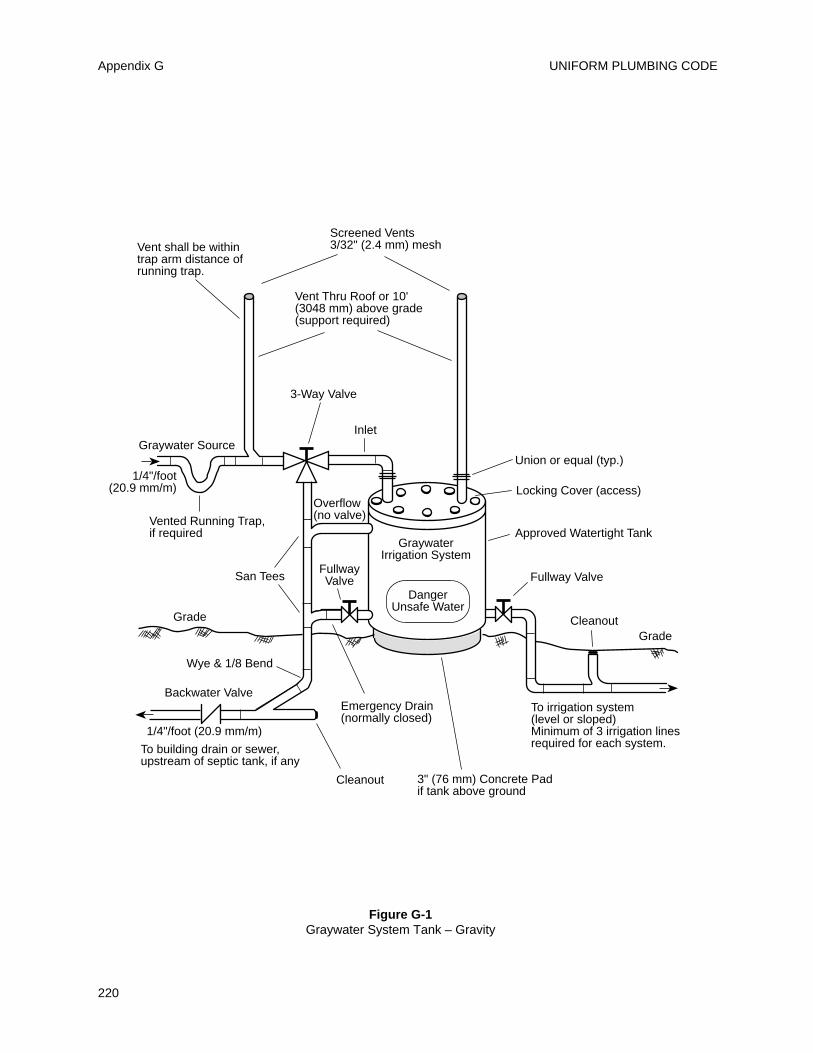
UNIFORM PLUMBING CODEAppendix G
220
Vent shall be withintrap arm distance ofrunning trap.
Vent Thru Roof or 10' (3048 mm) above grade(support required)
Screened Vents3/32" (2.4 mm) mesh
Graywater Source
1/4"/foot(20.9 mm/m)
Vented Running Trap,if required
3-Way Valve
Inlet
Union or equal (typ.)
Locking Cover (access)
Approved Watertight Tank
Grade
3" (76 mm) Concrete Padif tank above ground
Emergency Drain(normally closed)
Cleanout
1/4"/foot (20.9 mm/m)
To building drain or sewer, upstream of septic tank, if any
Backwater Valve
Wye & 1/8 Bend
Grade
San Tees
Overflow(no valve)
GraywaterIrrigation System
FullwayValve
To irrigation system(level or sloped)Minimum of 3 irrigation lines required for each system.
Cleanout
Fullway Valve
DangerUnsafe Water
Figure G-1Graywater System Tank – Gravity
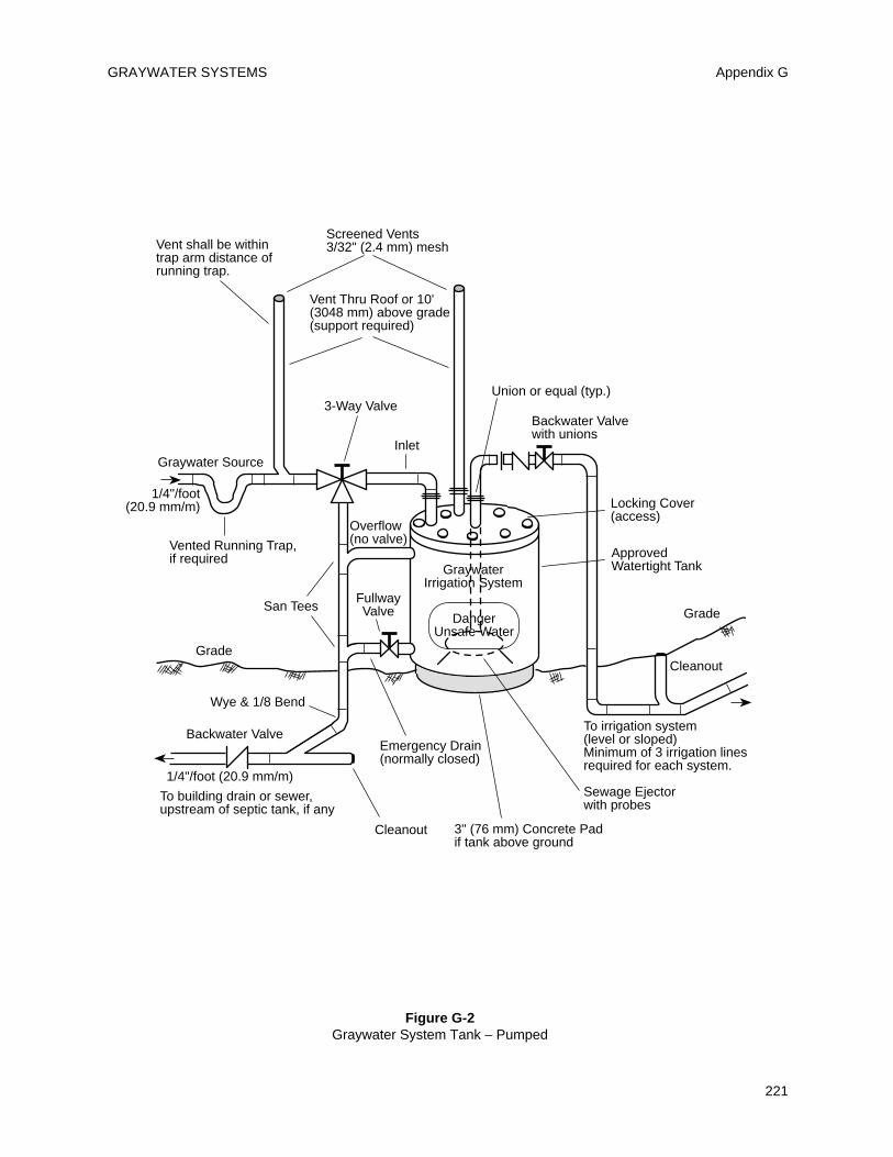
GRAYWATER SYSTEMS Appendix G
221
Vent shall be withintrap arm distance ofrunning trap.
Vent Thru Roof or 10'(3048 mm) above grade(support required)
Screened Vents3/32" (2.4 mm) mesh
Graywater Source
1/4"/foot(20.9 mm/m)
Vented Running Trap,if required
3-Way Valve
Inlet
Union or equal (typ.)
Locking Cover(access)
Approved Watertight Tank
Grade
3" (76 mm) Concrete Padif tank above ground
Emergency Drain(normally closed)
Cleanout
1/4"/foot (20.9 mm/m)
To building drain or sewer, upstream of septic tank, if any
Backwater Valve
Wye & 1/8 Bend
Grade
San Tees
Overflow(no valve)
GraywaterIrrigation System
FullwayValve
To irrigation system(level or sloped)Minimum of 3 irrigation lines required for each system.
Cleanout
DangerUnsafe Water
Sewage Ejectorwith probes
Backwater Valvewith unions
Figure G-2Graywater System Tank – Pumped
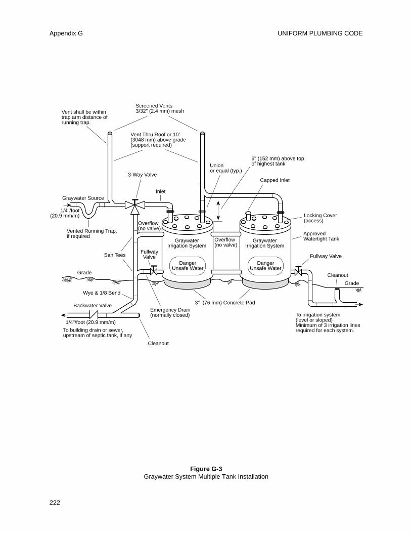
UNIFORM PLUMBING CODEAppendix G
222
Vent shall be withintrap arm distance ofrunning trap.
Vent Thru Roof or 10' (3048 mm) above grade(support required)
Screened Vents3/32" (2.4 mm) mesh
Graywater Source
1/4"/foot(20.9 mm/m)
Vented Running Trap,if required
3-Way Valve
Inlet
Unionor equal (typ.)
3" (76 mm) Concrete PadEmergency Drain(normally closed)
Cleanout
1/4"/foot (20.9 mm/m)
To building drain or sewer, upstream of septic tank, if any
Backwater Valve
Wye & 1/8 Bend
Grade
San Tees
Overflow(no valve)
FullwayValve
Grade
To irrigation system(level or sloped)Minimum of 3 irrigation lines required for each system.
Cleanout
Fullway Valve
GraywaterIrrigation System
DangerUnsafe Water
Locking Cover(access)
Approved Watertight TankGraywater
Irrigation System
DangerUnsafe Water
Overflow(no valve)
6" (152 mm) above topof highest tank
Capped Inlet
Figure G-3Graywater System Multiple Tank Installation
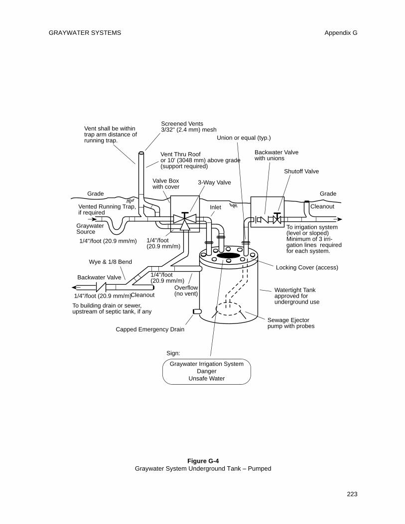
GRAYWATER SYSTEMS Appendix G
223
Vent shall be withintrap arm distance ofrunning trap.
Vent Thru Roof or 10' (3048 mm) above grade(support required)
Screened Vents3/32" (2.4 mm) mesh
GraywaterSource
1/4"/foot (20.9 mm/m)
Vented Running Trap,if required
Inlet
Locking Cover (access)
Watertight Tankapproved forunderground use
Grade
Capped Emergency Drain
Cleanout1/4"/foot (20.9 mm/m)
To building drain or sewer, upstream of septic tank, if any
Backwater Valve
Wye & 1/8 Bend
Grade
Overflow(no vent)
To irrigation system(level or sloped)Minimum of 3 irri-gation lines requiredfor each system.
Cleanout
Sewage Ejectorpump with probes
1/4"/foot (20.9 mm/m)
1/4"/foot(20.9 mm/m)
Shutoff Valve
Backwater Valvewith unions
Union or equal (typ.)
3-Way ValveValve Boxwith cover
Graywater Irrigation SystemDanger
Unsafe Water
Sign:
Figure G-4Graywater System Underground Tank – Pumped
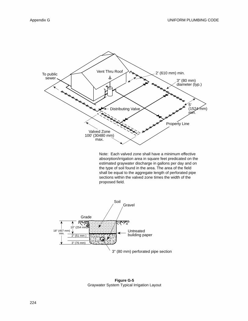
UNIFORM PLUMBING CODEAppendix G
224
Distributing Valve5'(1524 mm)min.
3" (80 mm)diameter (typ.)
2' (610 mm) min.To public sewer
Note: Each valved zone shall have a minimum effectiveabsorption/irrigation area in square feet predicated on theestimated graywater discharge in gallons per day and onthe type of soil found in the area. The area of the fieldshall be equal to the aggregate length of perforated pipesections within the valved zone times the width of theproposed field.
Vent Thru Roof
Property Line
Grade
SoilGravel
Untreatedbuilding paper
3" (80 mm) perforated pipe section
2" (51 mm )
3" (76 mm)
10" (254 mm)18" (457 mm)
min.
Valved Zone100' (30480 mm)
max.
Figure G-5Graywater System Typical Irrigation Layout
H 101.0 General
The provisions of this appendix shall apply to thedesign, construction, installation, and testing ofcommercial kitchen grease interceptors.
H 102.0 Waste Discharge Requirements
H 102.1 Waste discharge from fixtures andequipment in establishments which may containgrease, including but not limited to, scullery sinks,pot and pan sinks, dishwashing machines, soupkettles and floor drains located in areas wheregrease-containing materials may exist, may bedrained into the sanitary waste through theinterceptor when approved by the AdministrativeAuthority.
H 102.2 Toilets, urinals, and other similar fixturesshall not drain through the interceptor.
H 102.3 All waste shall enter the interceptorthrough the inlet pipe only.
H 103.0 Design
H 103.1 Interceptors shall be constructed inaccordance with the design approved by theAdministrative Authority and shall have a minimumof two compartments with fittings designed forgrease retention.
H 103.2 There shall be an adequate number ofmanholes to provide access for cleaning all areas ofan interceptor; a minimum of one (1) per ten (10) feet(3048 mm) of interceptor length. Manhole coversshall be gastight in construction having a minimumopening dimension of twenty (20) inches (508 mm).
H 103.3 In areas where traffic may exist theinterceptor shall be designed to have adequatereinforcement and cover.
H 104.0 Location
H 104.1 Each grease interceptor shall be so installedand connected that it shall be at all times easilyaccessible for inspection, cleaning, and removal ofthe intercepted grease. A grease interceptor may notbe installed in any part of a building where food ishandled. Location of the grease interceptor shallmeet the approval of the Administrative Authority.
H 104.2 Interceptors shall be placed as close aspractical to the fixtures it serves.
H 104.3 Each business establishment for which agrease interceptor is required shall have aninterceptor which shall serve only that establishment.
H 105.0 Construction Requirements
H 105.1.0 Purpose. Grease interceptors shall bedesigned to remove grease from effluent, and shallbe sized in accordance with this appendix. Greaseinterceptors shall also be designed to retain greaseuntil accumulations can be removed by pumping theinterceptor. It is recommended that a sample box belocated at the outlet end of all grease interceptors sothat the Administrative Authority can periodicallysample effluent quality.H 105.2.0 Dimension and ToleranceRequirements. Drawings shall be complete andshall show all dimensions, capacities, reinforcing andstructural design calculations.H 105.2.2 Grease interceptors shall have two (2)compartments. The inlet compartment shall be two-thirds (2/3) of the total capacity of the interceptor,shall have a minimum liquid volume of threehundred thirty three (333) gallons (1260 L) and in allcases shall be longer than the maximum inside widthof the interceptor. The outlet compartment shall havea minimum capacity of one-third (1/3) of the totalinterceptor capacity. The liquid depth shall not beless than two feet six inches (2' 6") (362 mm) normore than six feet (6') (1829 mm).H 105.2.3 All grease interceptors shall have at leastone (1) square foot (0.09 m2) of surface area for everyforty-five (45) gallons (170 L) of liquid capacity.H 105.2.4 Access to each grease interceptor shall beprovided by a manhole over the inlet and a manholeover the outlet. There shall also be an access manholefor each ten (10) feet (3048 mm) of length forinterceptors over twenty (20) feet (6096 mm) long.Each such access opening shall have a leak-resistantclosure (i.e., lid) that cannot slide, rotate or flip,exposing the opening when properly installed andwhich does not require the use of mechanical fasteners.
Note: The intention is that a child-resistant lid beprovided. Mechanical fasteners arerecommended to augment the safety of andensure positive closure of the lid.Manholes shall extend to grade, have a
minimum size of 20" (508 mm) diameter or 20" x 20"square (508 mm x 508 mm), and shall have agasketed cover at grade.
225
APPENDIX HRECOMMENDED PROCEDURES FOR DESIGN, CONSTRUCTION
AND INSTALLATION OF COMMERCIAL KITCHEN GREASE INTERCEPTORS
H 105.2.5 The inlet and outlet shall have a baffletee or similar flow device with a minimum crosssectional area equal to the required cross sectionalarea of the inlet. Each baffle shall extend from at leastfour (4) inches (102 mm) above the liquid level towithin at least twelve (12) inches (305 mm) of theinside floor of the interceptor.
H 105.2.6 Adequate partitions or baffles of sounddurable material shall be constructed betweencompartments of the grease interceptor and shallextend at least six (6) inches (152 mm) above theliquid level. Flow from inlet compartment to outletcompartment shall be through a quarter bend, orsimilar device equivalent in cross sectional area tothe inlet into the interceptor, and shall extend downto within twelve (12) inches (305 mm) of the insidefloor. Wooden baffles are prohibited.
H 105.2.7 Inlet, outlet and main baffle shall have afree vent area equal to the required cross sectionalarea of the inlet pipe.
H 105.2.8 The inside cover of the greaseinterceptor shall be minimum of nine (9) inches (229mm) above the liquid level over the entire surfacearea of the interceptor. The airspace shall have aminimum capacity equal to 12-1/2% of the greaseinterceptors liquid volume.
H 105.3.0 Structural Requirements
H 105.3.1 Grease interceptors shall be designed towithstand all anticipated loads.
H 105.3.2 Grease intercepters and covers shall bedesigned for an earth load of not less than fivehundred (500) pounds per square foot (24 kPa) whenthe maximum coverage does not exceed three (3) feet(914 mm). Each intercepter and cover shall bestructurally designed to withstand all anticipatedearth or other loads and to be installed level and on asolid bed. Wood covers are prohibited. Greaseinterceptors for installation in traffic areas shall bedesigned to withstand an AASHTO H20-44 wheelload, an additional three (3) foot (914 mm) earth loadwith an assumed soil weight of one hundred (100)pound per square foot (4.8 kPa), and thirty (30)pounds per square foot (1.4 kPa) fluid equivalentsidewall pressure.
H 105.3.3 Independent laboratory tests andengineering calculations certifying the greaseintercepter capacity and structural stability shall beprovided.
H 105.4.0 Material Requirements.
H 105.4.1 Concrete. Concrete shall have aminimum compressive strength of four thousand(4000) pounds per square inch (27579 kPa), and shallbe made with type II/V low-alkali portland cementconforming to ASTM C 150, including the optional
sulfate expansion requirement (table 4). Concreteshall have a maximum water/cementing materialsratio of 6 gal.(22.7 L)/sack of cement. Complyingwith the following ASTM designations: ASTM C 260-86, Specification for Air Entraining Admixtures forConcrete; ASTM C 33-86, Specification for ConcreteAggregates; ASTM C 94-86, Specification for ReadyMix Concrete; and ASTM C 618-85, Specification forFly Ash and Raw or Calcined Natural Pozzolan foruse as a Mineral Admixture in Portland CementConcrete.
H 105.4.2 Walls shall have a thickness of at leastthree (3) inches (76 mm), except where engineeringanalysis and production methods can justify a lesserthickness.
H 105.4.3 The minimum area of steel reinforcement(in both directions) of the structural elements shall be0.0015 times the gross cross-sectional area of thereinforced section, if of bars; and not less than three-fourths (3/4) as much if of welded wire fabric. Allreinforcement shall be protected with a minimum ofone (1) inch (25.4 mm) of concrete and shall complywith ASTM A 185-85, Specification for Steel WeldedWire Fabric, Plain for Concrete Reinforcement andASTM A 615, Specification for Deformed and PlainBillet-Steel Bars for Concrete Reinforcement. Tanksshall be of sufficient strength to resist stresses causedduring handling and installation without structuralcracking.
H 105.4.4 If repairs are necessary, they shall becarried out in accordance with the establishedpractices of the manufacturer in a manner thatinsures that the repaired interceptor meets therequirements of this appendix.
H 105.5.1 Steel. Steel grease interceptors shallcomply with the requirements for steel septic tanksin Section 4 of PS 1.
H 105.6.1 Fiberglass Reinforced Polyester.Fiberglass reinforced polyester grease interceptorsshall comply with the requirements for fiberglassreinforced polyester septic tanks in Section 4 of PS 1.
H 105.6.2 Polyethylene. Polyethylene greaseinterceptors shall comply with the requirements forpolyethylene septic tanks in Section 4 of PS 1.
H 105.7.0 Water Tight Testing
H 105.7.1 Water Testing - A sampling from eachmanufacturer’s production run shall be water tested.One sample shall be tested for each size interceptermanufactured. Sample intercepters shall beassembled per manufacturer’s instructions, set level,and water raised to the flow-line of the outlet fitting.
Intercepters shall show no leakage from sectionseams, pinholes, or other imperfections. Any leakageis cause for rejection. When leakage occurs
UNIFORM PLUMBING CODE
226
Appendix H
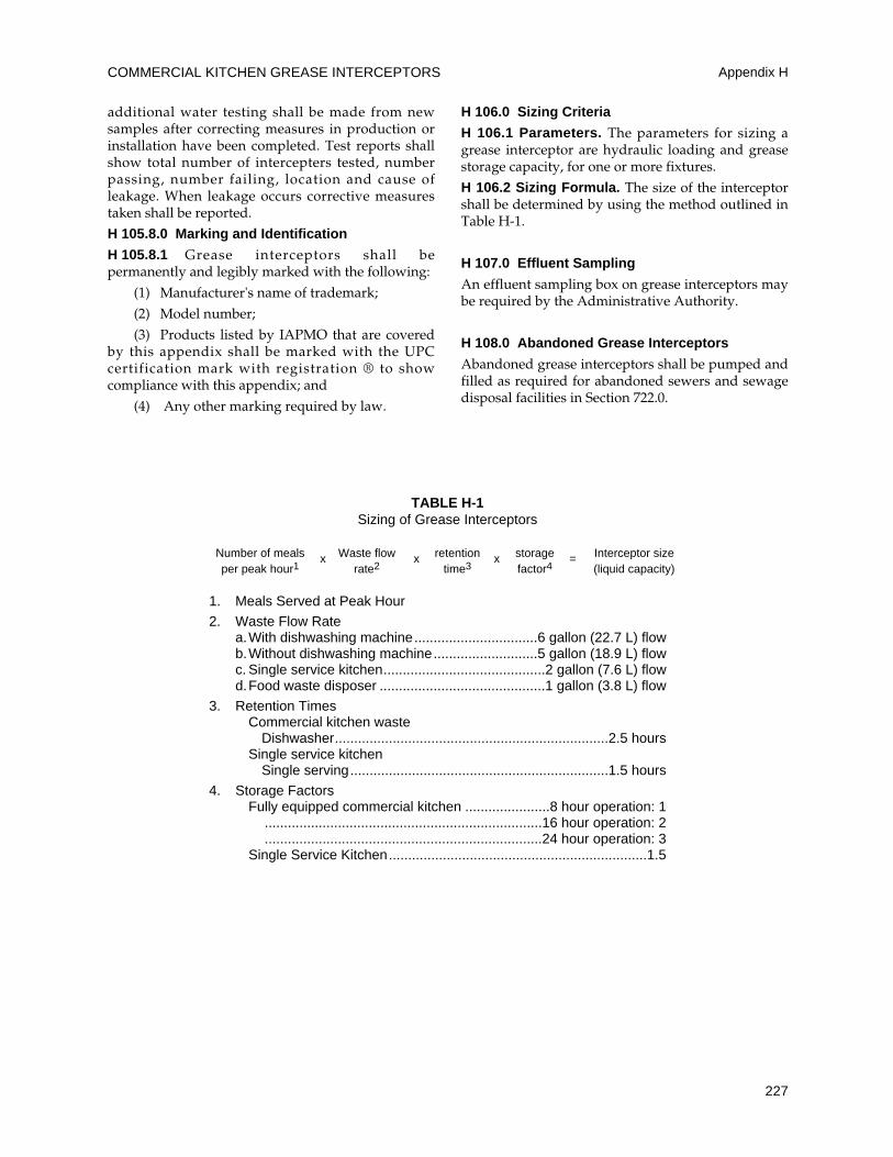
additional water testing shall be made from newsamples after correcting measures in production orinstallation have been completed. Test reports shallshow total number of intercepters tested, numberpassing, number failing, location and cause ofleakage. When leakage occurs corrective measurestaken shall be reported.
H 105.8.0 Marking and Identification
H 105.8.1 Grease interceptors shall bepermanently and legibly marked with the following:
(1) Manufacturer's name of trademark;
(2) Model number;
(3) Products listed by IAPMO that are coveredby this appendix shall be marked with the UPCcertification mark with registration ® to showcompliance with this appendix; and
(4) Any other marking required by law.
H 106.0 Sizing Criteria
H 106.1 Parameters. The parameters for sizing agrease interceptor are hydraulic loading and greasestorage capacity, for one or more fixtures.
H 106.2 Sizing Formula. The size of the interceptorshall be determined by using the method outlined inTable H-1.
H 107.0 Effluent Sampling
An effluent sampling box on grease interceptors maybe required by the Administrative Authority.
H 108.0 Abandoned Grease Interceptors
Abandoned grease interceptors shall be pumped andfilled as required for abandoned sewers and sewagedisposal facilities in Section 722.0.
COMMERCIAL KITCHEN GREASE INTERCEPTORS Appendix H
227
Number of meals Waste flow retention storage Interceptor size per peak hour1
xrate2
xtime3
xfactor4
=(liquid capacity)
1. Meals Served at Peak Hour
2. Waste Flow Ratea.With dishwashing machine................................6 gallon (22.7 L) flowb.Without dishwashing machine...........................5 gallon (18.9 L) flowc. Single service kitchen..........................................2 gallon (7.6 L) flowd.Food waste disposer ...........................................1 gallon (3.8 L) flow
3. Retention TimesCommercial kitchen waste
Dishwasher.......................................................................2.5 hoursSingle service kitchen
Single serving...................................................................1.5 hours
4. Storage FactorsFully equipped commercial kitchen ......................8 hour operation: 1
........................................................................16 hour operation: 2
........................................................................24 hour operation: 3Single Service Kitchen...................................................................1.5
TABLE H-1Sizing of Grease Interceptors

UNIFORM PLUMBING CODE
228
229
APPENDIX I
INSTALLATION STANDARDS
TABLE OF CONTENTS
PageIS 1-91e1 Non-Metallic Building Sewers .................................................................................................. 231
IS 2-90 Tile-Lined Roman Bathtubs ...................................................................................................... 237
IS 3-93e1 Copper Plumbing Tube, Pipe and Fittings ............................................................................... 243
IS 4-96 Tile-Lined Shower Receptors (and Replacements) ................................................................. 251
IS 5-92e1 ABS Building Drain, Waste, and Vent Pipe and Fittings .......................................................... 255
IS 6-95 Hubless Cast Iron Sanitary and Rainwater Systems ............................................................... 261
IS 7-90e1 Polyethylene (PE) Cold Water Building Supply ........................................................................ 263
IS 8-95e1 PVC Cold Water Building Supply and Yard Piping .................................................................. 265
IS 9-95e1 PVC Building Drain, Waste and Vent Pipe and Fittings ........................................................... 275
IS 10-93 DISCONTINUED
IS 11-87e1 ABS Sewer Pipe and Fittings ................................................................................................... 281
IS 12-93e1 Polyethylene (PE) for Gas Yard Piping .................................................................................... 285
IS 13-91 Protectively Coated Pipe .......................................................................................................... 289
IS 15-82 Asbestos Cement Pressure Pipe for Water Service and Yard Piping ..................................... 291
IS 16-84 Low Pressure Air Test for Building Sewers .............................................................................. 297
IS 18-85e1 Extra Strength Vitrified Clay Pipe in Building Drains ................................................................ 303
IS 20-98 CPVC Solvent Cemented Hot and Cold Water Distribution Systems ...................................... 305
IS 21-89e1 Welded Copper and Copper Alloy Water Tube ........................................................................ 315
IS 26-99 Trenchless Polyethylene (PE) Pipe for Sewer Laterals .............................................................323
e1Editorial Changes Only.

UNIFORM PLUMBING CODE
230
Installation and material of non-metallic buildingsewer piping shall comply with this standard and thecurrent edition of the Uniform Plumbing Codepublished by the International Association ofPlumbing and Mechanical Officials.
Note: The following sections of the UniformPlumbing Code apply to non-metallic building sewerpiping. The standard may include section numbers ormay omit section numbers which pertain to non-metallic sewers.
301.1 Minimum Standards310.0 Workmanship311.0 Prohibited Fittings and Practices313.0 Protection of Piping Materials and
Structures315.0 Trenching, Excavation and Backfill723.0 Building Sewer Test
103.5.3.5 Exceptions705.1 Types of Joints705.2 Use of Joints
316.2.3 Plastic Pipe to Other Materials
316.4 Prohibited Joints and Connections317.0 Increasers and Reducers
Chapter 7 Sanitary Drainage
GENERAL REQUIREMENTS
314.0 After inspection of the sewer pipe, carefullybackfill the trench as
315.0 prescribed by Sections 314.0 and 315.0 ofthe Uniform Plumbing Code.
723.0 The same water test procedure shall applyto all non-metallic house sewer materials asrequired in Section 723.0 of the UniformPlumbing Code.
718.0 Before laying non-metallic sewer pipe,prepare the bottom trench so that the pipingshall lay on a firm bed throughout its entirelength as required by Section 718.0 of theUniform Plumbing Code.
ABS OR PVC-DWV PIPE
301.1 Minimum StandardsABS or PVC Schedule 40 DWV pipe for usein domestic sewage, excluding specialwaste shall be installed in accordance withIAPMO Standards IS 5 and IS 9 (latest
edition), whichever is applicable. ABS orPVC Schedule 40 DWV pipe, IAPMO listed,may be used in sizes 2 inch (51 mm) andlarger.
716.0 Markings716.1 ABS Pipe. The pipe shall be marked on
two sides 180° apart or spirally in letters notless than 3/16 inch (4.8 mm) high in acontrasting color spaced at intervals of notmore than 2 feet (610 mm) and shall at leastconsist of:1. Manufacturer’s name or trademark;2. The nominal pipe size;3. The symbol ABS;4. The symbol DWV; and5. Products l isted by IAPMO that are
covered by this standard shall belabeled with the designated IAPMOcertification mark to show compliancewith this standard.
716.2 ABS Fittings. All fittings shall be markedon the body or hub on both sides. Themarking shall consist of:1. Manufacturer’s name or trademark;2. The symbol ABS; and3. Products l isted by IAPMO that are
covered by this standard shall belabeled with the designated IAPMOcertification mark to show compliancewith this standard.
716.3 PVC Pipe. The pipe shall be marked ontwo sides 180° apart or spirally in letters notless than 3/16 inch (4.8 mm) high in acontrasting color spaced at intervals of notmore than 2 feet (610 mm) and shall at leastconsist of:1. Manufacturer’s name or trademark;2. The nominal pipe size;3. The symbol PVC;4. The symbol DWV; and5. Products l isted by IAPMO that are
covered by this standard shall belabeled with the designated IAPMOcertification mark to show compliancewith this standard.
716.4 PVC Fittings. All fittings shall be markedon the body on both sides. The markingshall consist of:1. Manufacturer’s name or trademark;
231
Installation StandardFor
NON-METALLIC BUILDING SEWERS
IAPMO IS 1-91e1
2. The symbol PVC; and3. Products l isted by IAPMO that are
covered by this standard shall belabeled with the UPC logo to showcompliance with this standard.
718.0 Protection of Building SewersABS or PVC Schedule 40 pipe shall beinstalled a minimum of twelve (12) inches(305 mm) below the surface of the finishedgrade. Underground installation of flexiblethermoplastic sewer pipe shall be inaccordance with ASTM D 2321.
719.0 CleanoutsCleanouts, extended to within twelve (12)inches (305 mm) of grade, shall be ofmaterials listed for that use.
PVC SEWER PIPE
301.1 Minimum Standards301.1.1 Pipe
PVC, PSM, SDR 35, ASTM D 3034-96 andPVC, PS-46, ASTM F 789-95a Non-Pressure Pipe may be used in sizes four (4)inches (102 mm) and larger.
301.1.2 FittingsAll fittings shall be PVC or other listed non-metall ic materials having equivalentdurability and equal or greater strengths.
705.1 Types of JointsPVC sewer pipe shall be joined by listedcompression joints or by other approvedmethods. Pipe and fitting ends shall belubricated with an approved soap jelly orsoap solution to permit easy assembly.
705.3 Use of JointsPVC sewer pipe shall be installed using thesame type of jointing throughout, exceptwhen connecting to existing piping, piping ofother materials, in l ine repairs andmanholes. Transition connections to othermaterials shall be made by listed adapterfitt ings or a one-piece molded rubbercoupling with appropriate bushings for therespective material.
716.0 Markings716.1 PSM PVC pipe shall be clearly marked as
follows at intervals of five (5) feet (1524 mm) or less:1. Manufacturer’s name or trademark;2. Nominal pipe size;
3. The PVC cell classif ication, forexample12454-B;
4. The legend “Type PSM SDR-35 PVCsewer pipe”;
5. The ASTM designation D 3034; and6. Products listed by IAPMO that are
covered by this standard shall belabeled with the designated IAPMOcertification mark to show compliancewith this standard.
716.2 PSM PVC fittings shall be clearly marked asfollows:1. Manufacturer’s name or trademark;2. Nominal size;3. The material designation “PVC”;4. PSM;5. The ASTM designation D 3034; and6. Products l isted by IAPMO that are
covered by this standard shall belabeled with the designated IAPMOcertification mark to show compliancewith this standard.
716.3 PS-46 PVC pipe shall be clearly marked asfollows at intervals of five (5) feet (1524 mm) or less:1. Manufacturer’s name or trademark;2. Nominal pipe size;3. The PVC cell classification, for example
12164-B;4. Modulus indicator, for example T-1, T-2
or T-3;5. The legend “PS-46 PVC Gravity Sewer
Pipe”;6. The ASTM designation F 789;7. Manufacturer’s code to include day,
month, year, shift plant, and extruder ofmanufacturer; and
8. Products l isted by IAPMO that arecovered by this standard shall belabeled with the designated IAPMOcertification mark to show compliancewith this standard.
716.4 PSP PVC fittings shall be clearly marked asfollows:1. Manufacturer’s name or trademark;2. Nominal size;3. The material designation “PVC”;4. ASTM designation F 789; and5. Products listed by IAPMO that are
covered by this standard shall belabeled with the designated IAPMOcertification mark to show compliancewith this standard.
718.0 PVC sewer pipe shall not be installed lessthan twelve (12) inches (305 mm) below the
UNIFORM PLUMBING CODE
232
IS-1
surface of the finished grade and closer thantwenty-four (24) inches (610 mm) from abuilding. Underground installation of flexiblethermoplastic sewer pipe shall be inaccordance with ASTM D 2321.
719.0 CleanoutsCleanouts, extended to within twelve (12)inches (305 mm) of grade, shall be ofmaterials listed for such use.
POLY VINYL CHLORIDE (PVC) CORRUGATEDSEWER PIPE WITH A SMOOTH INTERIOR
AND FITTINGS
301.1 Minimum Standards301.1.1 Pipe. Corrugated PVC sewer pipe may be
used in sizes four (4) (102 mm), six (6) (152mm), eight (8) (203 mm) and ten (10) (254mm) inch diameters and shall conform toASTM F 949.The profile wall pipe corrugated PVC sewerpipe as intended for underground use innon-pressure applications for sanitarysewers, storm sewer, and perforated andunperforated pipes for subdrainage.
301.1.2 Fittings shall be PVC or other fittings havingequivalent durability or equal or greaterstrengths in accordance with ASTM F 949.
316.1 Types and Use of Joints. Corrugated PVCsewer pipe shall be
705.1 joined by Molded or ElastomericCompression Joints or by other
705.3 approved methods. Elastomeric seals(gaskets) shall meet the requirements ofASTM F 477. The lubricant used forassembly shall be as recommended by theseller and shall have no detrimental affecton the gasket or on the pipe and fittings.The PVC cement shall comply with ASTM D2564 and shall be used in conjunction with aprimer in compliance with ASTM F 656. Thesolvent cement shall be used only forbushings in accordance with ASTM D 2855.
716.0 Markings716.1 Corrugated PVC sewer pipe shall be marked
as follows at intervals of five (5) feet (1524mm) or less:1. Manufacturer’s name or trademark;2. Nominal Pipe size;3. The ASTM designation F 949;4. Type of plastic “PVC” and minimum cell
classification;5. Extrusion code, including date and
location of manufacture; and
6. Products l isted by IAPMO that arecovered by this standard shall belabeled with the designated IAPMOcertification mark with registration ® toshow compliance with this standard.
716.2 Corrugated PVC fittings shall be clearlymarked as follows:1. Manufacturer’s name or trademark;2. Nominal size;3. The ASTM designation F 949;4. Material designation “PVC”; and5. Products l isted by IAPMO that are
covered by this standard shall belabeled with the designated IAPMOcertification mark with registration ® toshow compliance with this standard.
718.0 Protection of Building Sewer. CorrugatedPVC sewer pipe shall not be installed lessthan twelve (12) inches (305 mm) below thesurface of the finished grade and closer thantwenty-four (24) inches (610 mm) from abuilding. Underground installation of flexiblethermoplastic sewer pipe shall be inaccordance with ASTM D 2321.
719.0 Cleanouts. Cleanouts, extended to withintwelve (12) inches (305 mm) of grade, shallbe of materials listed for such use.
ASBESTOS CEMENT SEWER PIPE
301.1 Minimum StandardsAsbestos cement sewer pipe shall be Type IIonly and may be used only in sizes four (4)inches (102 mm) and larger. Its use islimited to domestic sewage.
706.0 All fittings used with asbestos cement sewerpipe shall be asbestos cement or otherapproved non-metallic materials havingequivalent durability and providing fittingswith equal or greater strengths.
705.1 Asbestos cement sewer pipe and male endfittings shall be joined by means of a sleevecoupling and two rubber sealing ringssuitable for the particular size of the pipe andfittings for which they will be used. Therubber sealing rings shall be positioned ininterior grooves in the coupling.The assembled joint shall provide thenecessary compression of the rubber sealingrings to make a watertight joint. The crushstrength across the assembled joint shall beequivalent to the crush strength of the pipewith which it will be used.
NON-METALLIC BUILDING SEWERS
233
IS 1
UNIFORM PLUMBING CODE
234
705.1.1 The use of unmachined field-cut asbestoscement sewer pipe is permitted fornecessary length adjustments and at pointsof connection to other piping materials.These adaptions shall be made with either aone-piece molded rubber coupling withappropriate bushings or l isted adapterfittings.
705.1.2 Approved female fittings shall be providedwith interior grooves in the bell ends in whichrubber sealing rings, suitable for theparticular size of pipe with which the fittingswill be used, are placed. The compressedrubber sealing ring in the joined female (bell)fitting end shall provide a watertight joint.
705.1.3 Pipe and fitting ends shall be lubricated withan approved jelly or soap solution to permiteasy assembly.
705.1.4 A listed one-piece molded rubber couplingwith appropriate bushings may be used asan alternate means of connecting asbestoscement pipe and male end fittings.
705.1.5 Transition from asbestos cement sewer pipeto another material shall be made by listedadapter fittings, or a one-piece moldedcoupling with appropriate bushings for therespective material.
716.0 Markings716.1 Each standard and random length of listed
asbestos cement sewer pipe shall bemarked with:1. Manufacturer’s name or trademark;2. Nominal size;3. Class;4. Date of manufacture; and5. Products l isted by IAPMO that are
covered by this standard shall belabeled with the designated IAPMOcertification mark to show compliancewith this standard.
716.2 Each coupling sleeve of fitting shall beidentified by labeling or stenciling with:1. Nominal size;2. Class; and3. Products listed by IAPMO that are
covered by this standard shall belabeled with the designated IAPMOcertification mark to show compliancewith this standard.
718.0 No asbestos cement sewer pipe shall beinstalled less than twelve (12) inches (305mm) below the surface of the ground or
closer than two (2) feet (610 mm) to abuilding.
719.0 Cleanouts shall be asbestos cement or otherapproved materials of plug or cap typeinstalled with rubber ring compression joints.Cleanouts, extended to within twelve (12)inches (305 mm) of the surface, shall be ofmaterials approved for such use.
CONCRETE SEWER PIPE
301.1 Minimum Standards301.1.1 Pipe and Fittings
Concrete sewer pipe may be used in sizesfour (4) inches (102 mm) and larger.Concrete sewer pipe shall conform to ASTMC 14-80, Class 2. Transition to other typesor sizes of pipe may be made with listedconcrete pipe adapter fittings or listed one-piece molded rubber coupling withappropriate bushings or increasers.
705.1 Types of JointsConcrete sewer pipe and fittings shall bejoined by means of flexible rubber sealingrings, compressed to provide water-tight jointsconforming to ASTM C 443, or by listed one-piece molded rubber couplings, or hot-pouredjoints of listed hot-pour compounds. PortlandCement joints are prohibited except for repairsor connections to existing lines constructedwith such joints.Concrete sewer pipe shall be joined bygaskets furnished by the pipe manufacturerand installed according to themanufacturer’s instructions. Approvedlubricant shall be used when required for thetype of joint furnished.
705.2 Use of JointsExcept for points of connection to existingpiping at either end of the sewer, concretesewer pipe shall be laid using the same typeof jointing throughout.
716.0 Markings716.1 Concrete sewer pipe and fittings shall be
permanently and legibly marked with:1. Manufacturer’s name or trademark;2 Pipe class;3. Date of manufacture;4. Identification of the plant; and5. Products listed by IAPMO that are
covered by this standard shall belabeled with the designated IAPMO
IS 1
certification mark to show compliancewith this standard.
718.0 Grade, Support and Protection ofBuilding SewersConcrete sewer pipe shall be installed notless than twelve (12) inches (305 mm)below the ground and not closer than two(2) feet (610 mm) to a building.
719.0 CleanoutsCleanouts shall conform to type of jointingused and cleanouts extended to withintwelve (12) inches (305 mm) of grade, shallbe of materials listed for that use.
VITRIFIED CLAY PIPE
301.1 Minimum Standards301.1.1 Materials. Materials shall comply with the
appropriate standard in Table A of the UPC.Vitrified clay sewer pipe, extra strength only,may be used in sizes three (3) inches (76mm) and larger.
705.1 Types of JointsVitrified clay sewer pipe and fittings shall bejoined by means of preformed flexiblecompression joints or listed one-piecemolded rubber couplings.
705.1.1 Except at point of connection to existingpiping at either end of the sewer, vitrifiedclay sewer piping shall be laid using thesame type of jointing throughout.
705.1.2 When install ing clay pipe with flexiblecompression joints, the mating surfacesshall be wiped clean of dirt and foreignmatter. An approved lubricant shall beapplied to the joint surfaces. Spigot shallthen be seated full depth into the bell.
705.1.3 Listed one-piece molded rubber couplingsshall be permitted for use on vitrified claypipe and fittings, sizes three (3) inches (76mm) through twelve (12) inches (305 mm).
705.1.4 Transition to other types of materials orsizes may be made with the use of listedone-piece molded, rubber couplings withappropriate bushings or increasers.
716.0 Markings716.1 Vitrified clay sewer pipe and fittings shall be
permanently and legibly identified with:1. Manufacturer’s name or trademark, and2. Extra Strength or ES.
718.0 No vitrified clay sewer pipe shall be installedless than twelve (12) inches (305 mm)below the surface of the ground.
719.0 CleanoutsCleanouts shall conform to the type ofjointing used and cleanouts extended towithin twelve (12) inches (305 mm) of gradeshall be of materials approved for their use.
ADOPTED: 1957REVISED: 1966, 1971, 1973, 1975, 1976, 1982,1985, 1990, 1991
NON-METALLIC BUILDING SEWERS
235
IS 1

UNIFORM PLUMBING CODE
236
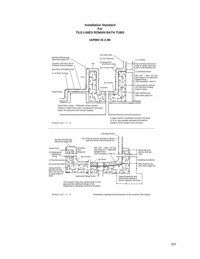
237
Installation StandardFor
TILE-LINED ROMAN BATH TUBS
IAPMO IS 2-90
Wood Floor Joists – Deflection of floor systemlimited to 1/360 of the span, including live and deadloads, for both point and uniform loading.
SCALE 1-1/2" = 1' - 0"
SCALE 1-1/2" = 1' - 0"
A vapor barrier consisting of at least one layerof 15 lb. type asphalt saturated felt shall bebetween wood surfaces and concrete.
(9) Wire Reinforcing(See back page 2e)
Ceramic Tile Floor Set inPortland Cement Mortar
Sub-Floor & Building Felt
2 x 6 Floor Furring
Finish Floor
2 x 4 Studs
Top of lining must be atleast 3" above spill-overpoint of the finished rim.
(7) Reinforcement
Min. 1/4" – Max. 1/2" perfoot slope to an approvedflanged drain(See exception, note 2)
Lining shall be pitched1/4" per foot to weepholes in drain
Wire Reinforcing(See back page 2e)
(10) Wall Finish
(3) Test Required
(2) WaterproofMembrane Lining
(8) Concrete Shell
12"+
The receptor must rest continuously on soilapproved for building footings or besupported by adequate structural members.
Approved Flange Drain
Illustrations reprinted with permission of the Ceramic Tile Institute
Finish Floor
(2) WaterproofMembraneLining
(7) Reinforcement
(8) Concrete Shell
Lining shall bepitched not lessthan 1/4" per footto weep holes indrain.
Wood Sill andAnchor Bolt perUBC
Building foundation
Wire Reinforcing(See back page 2e)
Special approval andreinforcing required iffixture supports structure.
(10) Wall Finish
(5) Corners
(3) WaterTestRequired
Min. 1/4" – Max. 1/2" perfoot slope to 2" approvedflanged drain(See exception, Note 2)
(4) Finish
4" Min.
Top of lining must be at least 3" abovespill-over point of the finished rim(9) Wire Reinforcing
(See back page 2e)
(5) Corners
(4) Finish
Tile
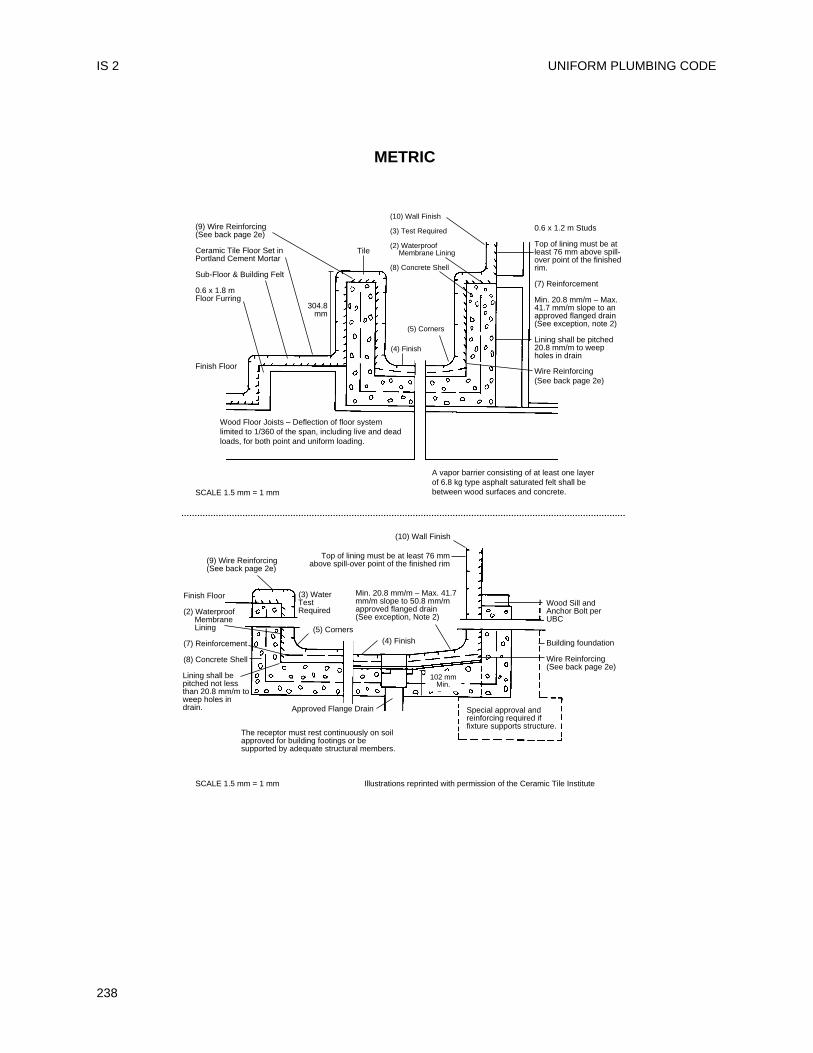
UNIFORM PLUMBING CODE
238
IS 2
Wood Floor Joists – Deflection of floor systemlimited to 1/360 of the span, including live and deadloads, for both point and uniform loading.
SCALE 1.5 mm = 1 mm
SCALE 1.5 mm = 1 mm
A vapor barrier consisting of at least one layerof 6.8 kg type asphalt saturated felt shall bebetween wood surfaces and concrete.
(9) Wire Reinforcing(See back page 2e)
Ceramic Tile Floor Set inPortland Cement Mortar
Sub-Floor & Building Felt
0.6 x 1.8 m Floor Furring
Finish Floor
0.6 x 1.2 m Studs
Top of lining must be atleast 76 mm above spill-over point of the finishedrim.
(7) Reinforcement
Min. 20.8 mm/m – Max.41.7 mm/m slope to anapproved flanged drain(See exception, note 2)
Lining shall be pitched20.8 mm/m to weepholes in drain
Wire Reinforcing(See back page 2e)
(10) Wall Finish
(3) Test Required
(2) WaterproofMembrane Lining
(8) Concrete Shell
304.8mm
Tile
The receptor must rest continuously on soilapproved for building footings or besupported by adequate structural members.
Approved Flange Drain
Illustrations reprinted with permission of the Ceramic Tile Institute
Finish Floor
(2) WaterproofMembraneLining
(7) Reinforcement
(8) Concrete Shell
Lining shall bepitched not lessthan 20.8 mm/m toweep holes indrain.
Wood Sill andAnchor Bolt perUBC
Building foundation
Wire Reinforcing(See back page 2e)
Special approval andreinforcing required iffixture supports structure.
(10) Wall Finish
(5) Corners
(3) WaterTestRequired
Min. 20.8 mm/m – Max. 41.7mm/m slope to 50.8 mm/mapproved flanged drain(See exception, Note 2)
(4) Finish
102 mmMin.
Top of lining must be at least 76 mmabove spill-over point of the finished rim(9) Wire Reinforcing
(See back page 2e)
(5) Corners
(4) Finish
METRIC
1. General
a. Inspection of Work – All surfaces prepared byothers shall be inspected by the tile installerbefore starting t i le work and allunsatisfactory condit ions reported to theAdministrative Authority. Starting tile work by theti le installer shall be considered asacceptance of surfaces prepared by others.
b. Surfaces – All surfaces to receive tile work shallbe clean, structurally sound, and conform inevery way to the local Building Code.
(Note: No tile work shall proceed until the panand drain construction has been inspected andapproved by the Administrative Authority, whererequired.)
2. Materials
a. Tile Quality and Grade – Tile shall comply withAmerican National Standard Specification forCeramic Tile, A137.1 (equivalent to andincorporating U.S. Dept. of Commerce SimplifiedPractice Recommendation, R61-61 and FederalSpecification SS-T-308b, Tile, Floor, Wall, andTrim Units, Ceramic).
b. Cement – Cement shall be portland cement typeI or type II, conforming to ASTM C-150.
c. Sand – Sand shall be damp, clean and gradedASTM C-144.
d. Water – Water shall be potable.e. Reinforcing shall be 3 inch x 3 inch (76 mm x
76 mm), 13 x 13 gage or 1-1/2 x 2 (38 mm x 51mm) mesh, 16 x 13 gage steel wire, conformingto ASTM A82 and A185.
f. Asphalt shall conform to Federal SpecificationSS-A-0666, Type Z, Grade 2, Class A.
g. Plastic Roof Cement shall conform to FederalSpecification SS-C153.
h. Waterproof Felt Membrane – The waterprooffelt membrane shall be at least 15 lb. (6.8 kg)asphalt saturated felt, conforming to Type l,Federal Specification HH-F-191 (a).
i. Plastic Membrane shall comply with applicablestandards listed in Table 14-1 of the UPC.
j. Other Membranes – Where the AdministrativeAuthority approves their use, non-metallic sub-pans or linings of lead sheets weighing not lessthan 4 lbs. per sq. foot (191.5 Pa) and copperpans of at least No. 24 B & S gage may be used.
k. Waterproofing Admixture – The mortar bed ofthe receptor shall be mixed with a waterproofadmixture, approved by the AdministrativeAuthority in the amounts allowed by suchapproval.
Currently Approved Mortar AdditivesAnti-Hydro – 1 qt. (0.95 I) per sack of cementPlastiment – 1 lb. (0.5 kg) of powder per sack ofcementPlastiment – 2 oz. (56.7 g) of fluid per sack ofcementSika 3A – 1 qt. (0.95 I) per sack of cementSuconem (Red Label) – 1 pint (0.47 I) per sackof cement
3. Installation
a. Drains – An approved type drain with sub-drainshall be installed with every such showermembrane. Flange of each sub-drain shall beaccurately set exactly level with sloping sub-floorand shall be equipped with a clamping ring orother approved device to make a t ightconnection between the membrane and the sub-drain. The sub-drain shall have weep holes intothe waste line. The drain shall be of such designthat there will be not less than 2 inch (51 mm)depth from the top of the sub-drain flange to topof the strainer. A ring of absorbent material mustbe placed around the weep holes to keep themopen when the finish materials are installed.
b. Sloping Sub-Floor and Membrane – All liningmaterials shall be pitched not less than onequarter (1/4) inch per foot (20.8 mm/m) to weepholes in the sub-drain by means of a smooth andsolidly formed sloping sub-base. All such liningmaterials shall extend upward on the side wallsof the tub to a point not less than four (4) inches(102 mm) above the top of the finished dam orthreshold and shall extend outward over the topof the rough threshold and be turned over andfastened on the outside face of the roughthreshold. All ledge tops within four (4) inches(102 mm) above the rough threshold shall becovered with the lining material. Non-metallicsub-pans or linings shall be built-up on the jobsite and shall consist of not less than three (3)layers of standard grade fifteen (15) pound (6.8kg) asphalt impregnated roofing felt. The bottomlayer shall be mopped to the formed sub-basewith hot asphalt and each succeeding layerthoroughly hot-mopped to that below, on thebasis of twenty (20) pounds (9.1 kg) of asphaltper layer per square. All corners shall becarefully fitted and shall be made strong andwatertight by folding or lapping, and each cornershall be reinforced with suitable woven glassfiber webbing hot-mopped in place. All folds,laps and reinforcing webbing shall extend atleast four (4) inches (102 mm) in all directionsfrom the corner and all glass fiber webbing shall
TILE-LINED ROMAN BATH TUBS IS 2
239
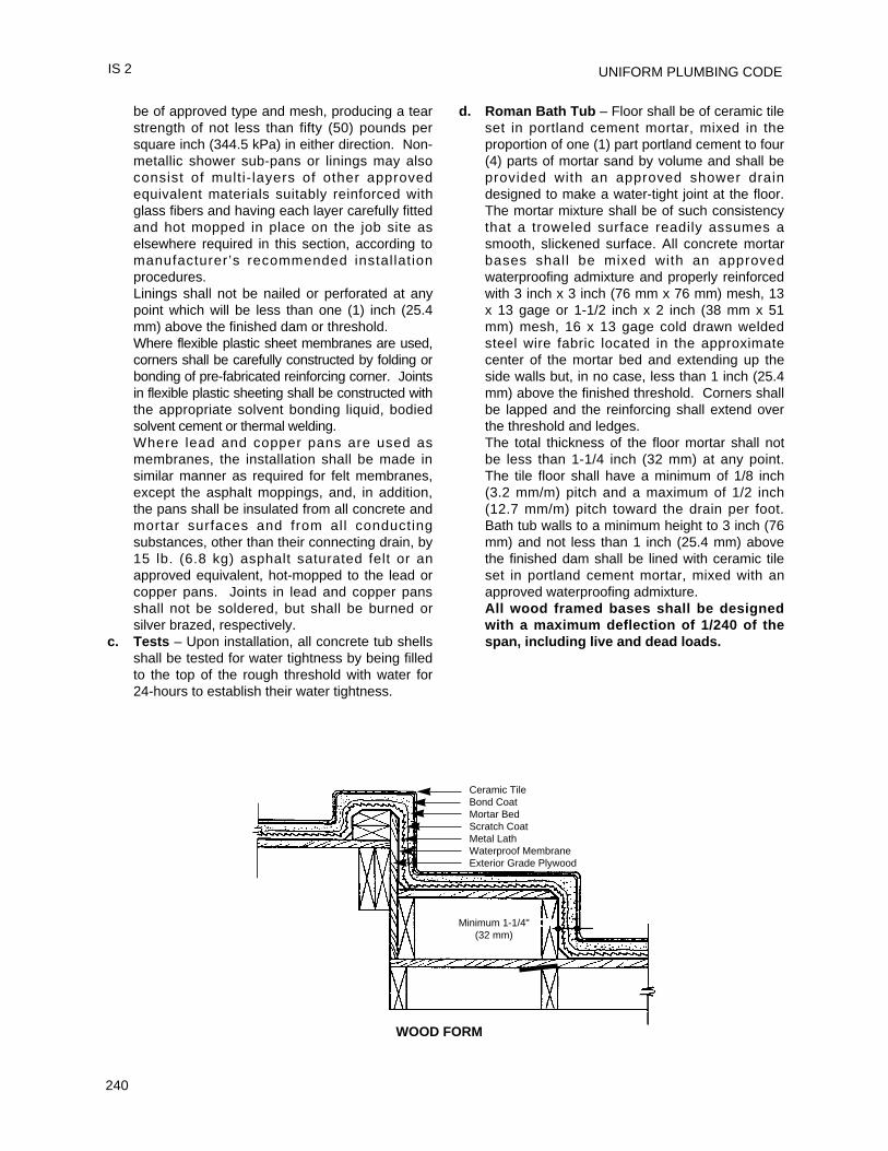
UNIFORM PLUMBING CODE
240
be of approved type and mesh, producing a tearstrength of not less than fifty (50) pounds persquare inch (344.5 kPa) in either direction. Non-metallic shower sub-pans or linings may alsoconsist of multi- layers of other approvedequivalent materials suitably reinforced withglass fibers and having each layer carefully fittedand hot mopped in place on the job site aselsewhere required in this section, according tomanufacturer’s recommended installationprocedures.Linings shall not be nailed or perforated at anypoint which will be less than one (1) inch (25.4mm) above the finished dam or threshold.Where flexible plastic sheet membranes are used,corners shall be carefully constructed by folding orbonding of pre-fabricated reinforcing corner. Jointsin flexible plastic sheeting shall be constructed withthe appropriate solvent bonding liquid, bodiedsolvent cement or thermal welding.Where lead and copper pans are used asmembranes, the installation shall be made insimilar manner as required for felt membranes,except the asphalt moppings, and, in addition,the pans shall be insulated from all concrete andmortar surfaces and from all conductingsubstances, other than their connecting drain, by15 lb. (6.8 kg) asphalt saturated felt or anapproved equivalent, hot-mopped to the lead orcopper pans. Joints in lead and copper pansshall not be soldered, but shall be burned orsilver brazed, respectively.
c. Tests – Upon installation, all concrete tub shellsshall be tested for water tightness by being filledto the top of the rough threshold with water for24-hours to establish their water tightness.
d. Roman Bath Tub – Floor shall be of ceramic tileset in portland cement mortar, mixed in theproportion of one (1) part portland cement to four(4) parts of mortar sand by volume and shall beprovided with an approved shower draindesigned to make a water-tight joint at the floor.The mortar mixture shall be of such consistencythat a troweled surface readily assumes asmooth, slickened surface. All concrete mortarbases shall be mixed with an approvedwaterproofing admixture and properly reinforcedwith 3 inch x 3 inch (76 mm x 76 mm) mesh, 13x 13 gage or 1-1/2 inch x 2 inch (38 mm x 51mm) mesh, 16 x 13 gage cold drawn weldedsteel wire fabric located in the approximatecenter of the mortar bed and extending up theside walls but, in no case, less than 1 inch (25.4mm) above the finished threshold. Corners shallbe lapped and the reinforcing shall extend overthe threshold and ledges.The total thickness of the floor mortar shall notbe less than 1-1/4 inch (32 mm) at any point.The tile floor shall have a minimum of 1/8 inch(3.2 mm/m) pitch and a maximum of 1/2 inch(12.7 mm/m) pitch toward the drain per foot.Bath tub walls to a minimum height to 3 inch (76mm) and not less than 1 inch (25.4 mm) abovethe finished dam shall be lined with ceramic tileset in portland cement mortar, mixed with anapproved waterproofing admixture.All wood framed bases shall be designedwith a maximum deflection of 1/240 of thespan, including live and dead loads.
IS 2
Minimum 1-1/4" (32 mm)
Ceramic TileBond CoatMortar BedScratch CoatMetal LathWaterproof MembraneExterior Grade Plywood
WOOD FORM
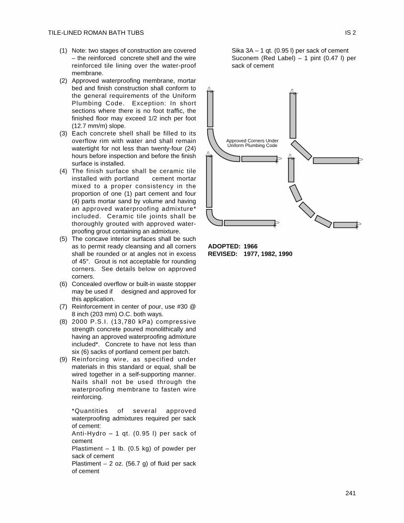
(1) Note: two stages of construction are covered– the reinforced concrete shell and the wirereinforced tile lining over the water-proofmembrane.
(2) Approved waterproofing membrane, mortarbed and finish construction shall conform tothe general requirements of the UniformPlumbing Code. Exception: In shortsections where there is no foot traffic, thefinished floor may exceed 1/2 inch per foot(12.7 mm/m) slope.
(3) Each concrete shell shall be filled to itsoverflow rim with water and shall remainwatertight for not less than twenty-four (24)hours before inspection and before the finishsurface is installed.
(4) The finish surface shall be ceramic tileinstalled with portland cement mortarmixed to a proper consistency in theproportion of one (1) part cement and four(4) parts mortar sand by volume and havingan approved waterproofing admixture*included. Ceramic t i le joints shall bethoroughly grouted with approved water-proofing grout containing an admixture.
(5) The concave interior surfaces shall be suchas to permit ready cleansing and all cornersshall be rounded or at angles not in excessof 45°. Grout is not acceptable for roundingcorners. See details below on approvedcorners.
(6) Concealed overflow or built-in waste stoppermay be used if designed and approved forthis application.
(7) Reinforcement in center of pour, use #30 @8 inch (203 mm) O.C. both ways.
(8) 2000 P.S.I. (13,780 kPa) compressivestrength concrete poured monolithically andhaving an approved waterproofing admixtureincluded*. Concrete to have not less thansix (6) sacks of portland cement per batch.
(9) Reinforcing wire, as specif ied undermaterials in this standard or equal, shall bewired together in a self-supporting manner.Nails shall not be used through thewaterproofing membrane to fasten wirereinforcing.
*Quantit ies of several approvedwaterproofing admixtures required per sackof cement:Anti-Hydro – 1 qt. (0.95 l) per sack ofcementPlastiment – 1 lb. (0.5 kg) of powder persack of cementPlastiment – 2 oz. (56.7 g) of fluid per sackof cement
Sika 3A – 1 qt. (0.95 l) per sack of cementSuconem (Red Label) – 1 pint (0.47 l) persack of cement
ADOPTED: 1966REVISED: 1977, 1982, 1990
TILE-LINED ROMAN BATH TUBS IS 2
241
Approved Corners UnderUniform Plumbing Code

UNIFORM PLUMBING CODE
242
Installation and material of copper tube, pipe andfittings in drainage, vent, and water systems shallcomply with this standard and the current edition ofthe Uniform Plumbing Code, published by theInternational Association of Plumbing andMechanical Officials (IAPMO).
Note: The following sections of the UniformPlumbing Code shall apply.
Table 14-1 StandardsASTM B 42-93 Specif ication for Seamless
Copper Pipe, Standard SizesASTM B 75-95a Specif ication for Seamless
Copper TubesASTM B 88-96 Specif ication for Seamless
Copper Water TubeASTM B 302-97 Specif ication for Threadless
Copper PipeASTM B 306-96 Specification for Copper Drainage
Tube (DWV)ASTM B 828-92e1 Standard Practice for Making
Capillary Joints by Soldering ofCopper and Copper Alloy Tubeand Fittings
ANSI B 16.18 Cast Copper Alloy Solder-Joint (R-1994) Pressure FittingsANSI B 16.22-95 Wrought Copper and Copper Alloy
Solder-Joint Pressure FittingsANSI B 16.23-92 Cast Bronze Solder-Joint
Drainage Fittings - DWVANSI B 16.29-86 Wrought Copper and Copper Alloy
Solder-Joint Drainage Fittings
301.1 Minimum standards903.2 Use of copper tubing
701.1.4 Underground drainage and vent piping811.1 Chemical or industrial waste piping604.2 Water piping604.3 Marking of tubing604.4 Flexible Water Connectors
704.4.1 Closet Flanges707.1 Cleanouts310.0 Workmanship311.0 Prohibited fittings and practices313.0 Protection of piping materials and
structures314.0 Hangers and supports, horizontal and
vertical piping103.5.3 Test
701.0 Materials, drainage piping
903.0 Materials, vent piping316.1 Types of Joints
316.1.2 Wiped Joints316.1.3 Solder and sweat606.1.1 Flared Joints606.2.1 Use of joints, copper water tube
316.2 Special Joints316.2.1 Copper tubing to screw pipe joints705.4.3 Ground Joint, Flared or Ferrule
Connections316.4 Prohibited joints and connections317.0 Increasers and reducers604.0 Materials604.1 Water piping604.7 Restriction of Used Piping608.0 Relief Valve Drain609.0 Installation, Inspection, Testing610.0 Size of potable piping
Appendix A Chart A-4 Friction loss per 100 ft. (30.5 m)Appendix D D 1.0 Materials, rain water piping
D 2.0 Materials, roof drains
301.1 Minimum Standards301.1.1 Materials. Materials shall comply with the
appropriate standard in Table 14-1 of theUPC.Note: The nominal or standard size ofcopper plumbing tube is always 0.125 inch(3.8 mm) or one-eighth (1/8) inch (3.2mm) smaller than the actual outsidediameter dimension of the tube. Forexample, 3 inch (76 mm) nominal sizecopper plumbing tube measures 3-1/8inch (79 mm) O.D., 1/2 inch (12.7 mm)nominal size copper plumbing tubemeasures 5/8 inch (15.9 mm) O.D., etc.
301.1.2 Markings. Markings shall be visible forinspection. Products listed by IAPMO thatare covered by this standard shall belabeled with the UPC certification mark.
301.1.2.1 Tube and Threadless Pipe.Water tube (Types K, L, M), drainage tube(Type DWV), and threadless pipe (TP),shall bear the following incised marking atnot over 18 inch (457 mm) intervals:(a) Manufacturer’s name or trademark;(b) Tube type; and(c) Country of origin.
243
Installation StandardFor
COPPER PLUMBING TUBE, PIPE AND FITTINGS
IAPMO IS 3-93e1
301.1.2.2 Pipe (Copper and Copper Alloy)Pipe shall bear the following incisedmarking at not over 18 inch (457 mm)intervals:(a) Manufacturer’s name or trademark;
and(b) Pipe type.
301.1.2.3 FittingsFittings shall bear the following markings:(a) Manufacturer’s name or trademark,
and(b) "DWV" on drainage fittings.
316.1 Type of Joints316.1.1 General Information
Copper tube and fittings may be joined ina number of ways, depending on thepurpose of the system. Soldering andbrazing with capillary fittings are themethods used most.The American Welding Society definessoldering as a joining process which takesplace below 840°F (449°C) and brazing asa similar process which occurs above840°F (449°C) but below the melting pointof the base metals. In actual practice forcopper systems, most soldering is done attemperatures from about 350°F (177°C) to550°F (288°C), while most brazing is doneat temperatures ranging from 1100°F(593°C) to 1500°F (816°C) . The choicebetween soldering or brazing will generallydepend on operating conditions. Solderjoints are generally used where the servicetemperature does not exceed 205°F(96°C), while brazed joints can be usedwhere greater strength is required, orwhere system temperatures are as high as400°F (204°C) .Mechanical joints are used frequently forunderground tubing, for joints where theuse of heat is impractical and for jointsthat may have to be disconnected fromtime to time.
316.1.1.1 Fittings for Soldered, Brazed, andFlared JointsFittings are available in all standard tubesizes and in a wide variety of types tocover needs for plumbing. They can beeither soldered or brazed, althoughbrazing cast f i t t ings requires care.Wrought copper pressure fittings are alsoavailable over a wide range of sizes andtypes. These, too, can be joined by eithersoldering or brazing and wrought fittingsare preferred where brazing is the joiningmethod. Otherwise, the choice between
cast and wrought fittings is largely amatter of the user’s preference. Flared-tube fitt ings provide metal-to-metalcontact similar to ground joint unions; bothcan be easily taken apart andreassembled. They are especially usefulwhere residual water cannot be removedfrom the tube and soldering is difficult.Flared joints may be required where a firehazard exists and the use of a torch tomake soldered or brazed joints is notallowed. Also, soldering under wetconditions can be very difficult and flaredjoints are preferred under suchcircumstances.
316.1.1.2 SoldersNote: Users of the Uniform PlumbingCode are reminded that provisions of theFederal Clean Drinking Water Act of1986, which all must obey, forbid the useof solder which contains in excess of0.2% of lead, by volume in potable watersystems. The provisions of the act areincorporated in all ordinances, statutes,state and municipal regulations byreference and by operation of law.The selection of a solder depends on theoperating pressure and temperature of theline. Consideration should also be givento the stresses on the joint caused bythermal expansion and contraction.However, stresses due to temperaturechanges should not be significant in twocommonly encountered cases: when tubelengths are short, or when expansionloops are used in long tube runs.Solder is generally used in wire form, butpaste-type solders are also available.These are finely granulated solders insuspension in a paste flux. When usingpaste-type solders, observe these fourrules:1. Wire solder must be applied in
addition to the paste to fill the voidsand assist in displacing the flux,otherwise the surfaces may be well"tinned" and yet there may not be agood joint with a continuous bond.
2. The paste mixture must be thoroughlystirred if it has been standing in thecan for more than a very short time,as the solder has a tendency to settlerapidly to the bottom.
3. The flux cannot be depended on toclean the tube. Cleaning should bedone manually as is recommended forany other flux and solder.
UNIFORM PLUMBING CODE
244
IS 3
4. Remove any excess flux.Solders are available containing smallamounts of silver or other additives toimpart special properties. Such soldersmay require special f luxes. Themanufacturer’s recommendations shouldbe consulted regarding proper proceduresand fluxes for such solders and about theexpected properties.
316.1.1.3 Soldering FluxThe functions of the soldering flux are toremove residual traces of oxides, topromote wetting and to protect the surfacesto be soldered from oxidation duringheating. The flux should be applied to cleansurfaces and only enough should be usedto lightly coat the areas to be joined.An oxide fi lm may reform quickly oncopper after i t has been cleaned.Therefore, the flux should be applied assoon as possible after cleaning.
CAUTIONCareless workmanship, especially duringflux applications, can result in corrosion ofthe tube long after the system has beeninstalled. If excessive flux is used, theresidue inside the tube can causecorrosion. In an extreme case, suchresidual f lux can actually lead toperforation through the tube wall causingleakage. To guard against this danger, it isimportant (1) to choose a flux that is nottoo corrosive, and (2) to use only theminimum amount actually needed to makethe joint.
316.1.2 Solder JointsSoldering and brazing both involve basicsteps, which must be executed with careand craftsmanship. The steps are:(1) Measuring(2) Cutting(3) Reaming(4) Cleaning(5) Fluxing(6) Assembly and support(7) Heating(8) Applying the filler metal(9) Cooling and cleaningEach step contributes to a strong,
dependable joint.316.1.2.1 Measuring
Measuring the length of each tubesegment must be accurate. Inaccuracycan compromise joint quality. If the tube istoo short it will not reach all the way into
the socket of the fitting and a proper jointcannot be made. If the tube segment istoo long there is a danger of cocking thetube in the fitting and putting strain on thesystem which could affect service life.
316.1.2.2 CuttingOnce the tube is measured it can be cut.Cutting can be accomplished in a numberof different ways to produce a satisfactorysquare end. The tube can be cut with adisc-type tube cutter, a hacksaw, anabrasive wheel, or with a stationary orportable bandsaw. Care must be taken thatthe tube is not deformed while being cut.Regardless of the method, the cut must besquare with the run of the tube so that thetube will seat properly in the fitting socket.
316.1.2.3 ReamingAll pipe and tube shall be reamed to thefull I.D. of the pipe and tube.Tools used to ream tube ends include thereaming blade on the tube cutter, half-round or round files, a pocket knife and asuitable deburring tool. With annealedtube, care must be taken not to deform thetube end by applying too much pressure.Both the inside and the outside of the tubemay require removal of the burr.
316.1.2.4 CleaningThe removal of oxides and surfaces soil iscrucial if filler metal is to flow properly intothe joint. Unremoved oxide, surface soiland oil can interfere with the strength ofthe joint and cause failure.Mechanical cleaning is a simple operation.The end of the tube should be abradedlightly using sand cloth or nylon abrasivepads for a distance only slightly more thanthe depth of the fitting socket. The socketof the fitting should also be cleaned usingsand cloth, abrasive pads, or a properlysized fitting brush.Copper is a relatively soft metal. If toomuch material is removed, a loose fit willresult and interfere with satisfactorycapillary action in making the joint. Thecapillary space between tube and fitting isapproximately 0.004 inch (0.10 mm).Solder or brazing filler metal can fill thisgap by capillary action. This spacing iscritical for the filler metal to flow, into thegap and form a strong joint.Surfaces once cleaned should not betouched with bare hands or oily gloves.Skin oils, lubricating oils and greaseimpair solder flow and wetting.
COPPER PLUMBING TUBE, PIPE AND FITTINGS
245
IS 3
UNIFORM PLUMBING CODE
246
316.1.2.5 FluxingStir the flux before use. A good flux willdissolve and remove traces of oxide fromthe cleaned surfaces to be joined, protectthe cleaned surfaces from reoxidationduring heating and promote wetting of thesurfaces by the solder. A thin, evencoating of flux should be applied with abrush to both tube and fitting. Do not applywith fingers. Chemicals in the flux can beharmful if carried to the eyes or open cuts.
316.1.2.6 Assembly and SupportAfter both tube and fitting surfaces areproperly fluxed, they should be assembled,making sure the tube seats against thebase of the fitting socket. A slight twistingmotion ensures even distribution by theflux. Remove excess flux. Care must betaken to assure that the tube and fittingsare properly supported with a uniformcapillary space around the entirecircumference of the joint. Uniformity ofcapillary space will ensure good filler metalpenetration if the guidelines of successfuljoint making are followed. Excessive jointclearance can cause the filler metal tocrack under stress or vibration.The joint is now ready for soldering. Jointsprepared and ready for soldering shouldbe completed the same day and not leftunfinished overnight.
316.1.2.7 HeatingBecause an open flame may be used forsoldering, and because flammable gasesare used, safety precautions must beobserved. The heat is generally appliedusing an air/fuel torch. Such torches useacetylene or an LP gas. Electricresistance tools can also be used.Heating should begin with the flameperpendicular to the tube. The coppertube conducts the initial heat into thefitting socket for even distribution of heatinside and out. The extent of thispreheating depends upon the size of thejoint. Experience will indicate the amountof time needed. The flame should now bemoved onto the fitting. Then move theflame from the fitting socket back onto thetube a distance equal to the depth of thefitting socket. Touch the solder to the joint.If the solder does not melt, remove it andcontinue the heating process. Be carefulnot to overheat or to direct the flame intothe fitting cup. This could cause the flux toburn and destroy its effectiveness. When
the melting temperature of the solder hasbeen reached, heat may be applied to thebase of the cup to aid capillary action indrawing the solder into the cup.
316.1.2.8 Applying the Filler MetalFor tube in a horizontal position, startapplying the solder slightly off-center atthe bottom of the joint. Proceed across thebottom of the fitting and up to the topcenter position. Return to the point ofbeginning, overlap the starting point, andthen proceed up the incompleted side tothe top, again, overlapping the solder.For joints in the vertical position, a similarsequence of overlapping passes shouldbe made, starting wherever is convenient.Molten solder will be drawn into the jointby capillary action regardless of whetherthe solder is being fed upward, downwardor horizontally.
316.1.2.9 Cooling and CleaningAfter the joint has been completed, naturalcooling is best. Shock cooling with watermay cause unnecessary stress on thejoint and result in eventual failure. Whencool, clean off any remaining flux with awet rag.
316.1.3 Brazed JointsBrazing is the second most commonlyused method for joining copper tube.Making brazed joints is similar to makingsoldered joints with respect to measuring,cutting, reaming, cleaning, assembly andsupport. And as in soldering, the brazingfiller metal is melted by the heat of thetube and fitting and drawn into the joint bycapillary action.The major differences between solderingand brazing are the:• Type of flux used,• Composition of filler metal, and• Amount of heat required to melt the fillermetal.
316.1.3.1 Brazing FluxThe fluxes used for brazing copper jointsare different in composition from solderingfluxes. The two types cannot be usedinterchangeably. Brazing fluxes are waterbased, whereas most soldering fluxes arepetroleum based. Similar to solderingfluxes, brazing fluxes dissolve and removeresidual oxide from the metal surfaces,protect the metal from reoxidation duringheating and promote wetting of thesurfaces to be joined by the brazing fillermetal.
IS 3
Fluxes also provide the craftsman with anindication of temperature. Application ofthe flux is the same as when soldering. Ifthe outside of the fitting and the heat-affected area of the tube are covered withflux (in addition to the end of the tube andthe cup), oxidation will be prevented andthe appearance of the joint will be greatlyimproved.
316.1.3.2 Brazing Filler MetalsThere are two general types of brazingfiller metal used for joining copper tube.Classified according to their components,they are: BCuP (Brazing-Copper-Phosphorus) and BAg (Brazing-Silver).BCuP filler metals are preferred for joiningcopper tube and fittings. The phosphorusin them acts as a fluxing agent and thelower percentage of silver makes themrelatively low cost. When using coppertube, wrought copper fittings and BCuPbrazing filler metal, fluxing is optional.However, when cast fittings are brazed,flux must be used.
316.1.3.3 HeatingOxy/fuel torches are generally used forbrazing because of their highertemperatures required. Recent innovationsin tip design make air/fuel torches usefulon a wider range of sizes for brazing.When working at brazing temperatures,safety precautions must be followed andcare taken to protect both the operatorand the materials being used.The heating operation is the same as forsoldering. First preheat the tube and thenthe tube and fitting. When the filler metalstarts to melt, apply heat at the base ofthe fitting socket to help draw the brazingfiller metal in by capillary action.
316.1.3.4 Applying Brazing Filler MetalRemember to allow the heat of the joint,not the flame, to melt the filler metal. Themelted filler metal will be drawn into thejoint by capillary action. It is very importantthat the flame be in continuous motion. Itmust not be allowed to remain on any onepoint long enough to burn through thetube or fitting.If the filler metal fails to flow, or has thetendency to ball-up, it indicates either thatthere is oxide on the surfaces being joinedor that the parts to be joined are not hotenough. If the filler metal refuses to enterthe joint, the fitting cup is not hot enough.If it tends to flow over the outside of either
part of the joint, it indicates that part isoverheated. When the joint is completed,a continuous fi l let should be visiblecompletely around the joint.Larger diameter tube is more difficult toheat to the desired temperature. The use ofa heating tip or rosebud may be necessaryto maintain the proper temperature over thearea being brazed. Once total heat controlis attained, follow the same proceduresused for smaller tube.
316.1.3.5 Cooling and CleaningWhen the brazed joint is finished, allow itto cool naturally. Flux residues and someoxides formed by heating can be removedby washing with hot water and brushingwith a stainless steel wire brush.
606.1.1 Flared Joints606.1.1.1 Flared Joints with Impact Flaring Tools
Step 1 Cut the tube to the requiredlength.
Step 2 Remove all burrs. This is veryimportant to assure metal-to-metal contact.
Step 3 Slip the coupling nut over the endof the tube.
Step 4 Insert flaring tool into the tubeend.
Step 5 Drive the flaring tool by hammerstrokes, expanding the end of thetube to the desired flare. Thisrequires a few moderately lightstrokes.
Step 6 Assemble the joint by placing thefitting squarely against the flare.Engage the coupling nut with thefitting threads. Tighten with twowrenches, one on the nut andone on the fitting.
606.1.1.2 Flared Joints with Screw-Type FlaringToolsSteps 1-3 Same as for impact f laring
previously described.Step 4 Clamp the tube in the flaring
block so that the end of thetube is slightly above the faceof the block.
Step 5 Place the yoke of the flaringtool on the block so that thebeveled end of the compressorcone is over the tube end.
Step 6 Turn the compressor screwdown firmly, forming the flarebetween the chamber in theflaring block and the beveledcompressor cone.
COPPER PLUMBING TUBE, PIPE AND FITTINGS IS 3
247
Step 7 Remove the flaring tool. Thejoint can now be assembled asin Step 6 for impact flaring.
610.0 Sizing, VelocityNote: There are various hydraulicformulas for the flow of water in pipes.With high velocity and attendant turbulentflow, there can be excessive noise andpiping wear.The designer should aim for maximumflow velocities in the range of five to eightfeet per second to minimize noise anderosion problems. For the smallest tubesizes, the designer is wise to work at thebottom of this range, as a maximum, toguard against local high velocit iesbuilding up due to faulty workmanship(e.g. burrs at tube ends which are notproperly reamed) or unusually numerouschanges in flow direction.
GENERAL INFORMATION
It is not possible to cover all the variables of aplumbing system; however, the following informationmay prove helpful:Expansion Loops – Copper tube, like all pipingmaterials, expands and contracts with temperaturechanges. Therefore, in a copper tube systemsubjected to excessive temperature changes, the linetends to buckle or bend when it expands unlesscompensation is built into the system. Severestresses on the joints may also occur. Such stresses,buckles, or bends are prevented by the use ofexpansion joints or by installing offsets, “U” bends,coil loops, or similar arrangements in the tubeassembly. These specially shaped tube segmentstake up expansion and contraction without excessivestress. The expansion of a length of copper tube maybe calculated from the formula:
Temperature Rise (°F) x Length (feet) x 12 (inches per foot) x
Expansion Coefficient (in. per in. per °F) =Expansion (inches), or
Temperature Rise (°C) x Length (meter) x 1000 (mm per meter) x
Expansion Coefficient (mm per mm per °C) =Expansion (mm).
Calculations for expansion and contraction should bebased on the average coefficient of expansion ofcopper which is 0.0000094 per °F (1.692 x 10⁻⁵ per°C), between 70°F (21°C) and 212°F (100°C). For
example, the expansion of each 100 feet (3048 mm)of length of any size tube heated from roomtemperature (70°F) (21°C) to 170°F (77°C) (a 100°F(38°C) rise) is 1.128 inches (28.7 mm).
100° x 100 ft x 12 in./ft x 0.0000094 in./in./°F = 1.128 in., or
55.6° x 30.48 m x 1000 mm/m x 1.692 x 10⁻⁵
mm/mm/°C = 28.7 mm
Tube Supports
Vertical Piping - See Section 314.0
Horizontal Piping - See Section 314.0
Bending
Copper tube, properly bent, will not collapse on theoutside of the bend and will not buckle on the insideof the bend. Tests demonstrate that the burstingstrength of a bent copper tube can be greater than itwas before bending. Because copper is readilyformed, expansion loops and other bends necessaryin an assembly are quickly and simply made if theproper method and equipment are used. Simplehand tools employing mandrels, dies, forms, andfillers, or power-operated bending machines areused.Both annealed tube and bending-temper tube can bebent with hand benders. The proper size bender foreach size tube must be used. Usually the size of thetool corresponds to the nominal outside diameter ofthe tube, not the standard tube size. For a guide tothe typical bend radii, see the following bendingguide for copper tube.
ADOPTED: 1969REVISED: 1973, 1975, 1987, 1989, 1993
UNIFORM PLUMBING CODE
248
IS 3
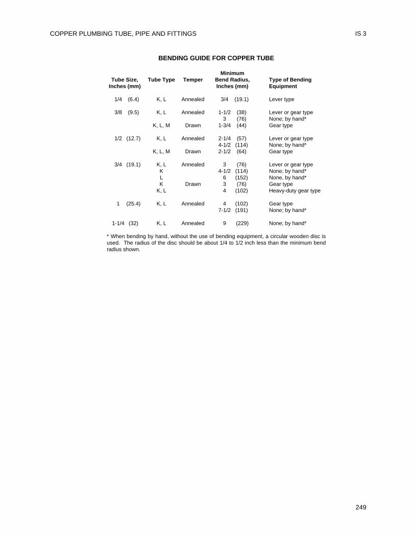
COPPER PLUMBING TUBE, PIPE AND FITTINGS IS 3
249
BENDING GUIDE FOR COPPER TUBE
MinimumTube Size, Tube Type Temper Bend Radius, Type of Bending
Inches (mm) Inches (mm) Equipment
1/4 (6.4) K, L Annealed 3/4 (19.1) Lever type
3/8 (9.5) K, L Annealed 1-1/2 (38) Lever or gear type3 (76) None; by hand*
K, L, M Drawn 1-3/4 (44) Gear type
1/2 (12.7) K, L Annealed 2-1/4 (57) Lever or gear type4-1/2 (114) None; by hand*
K, L, M Drawn 2-1/2 (64) Gear type
3/4 (19.1) K, L Annealed 3 (76) Lever or gear typeK 4-1/2 (114) None; by hand*L 6 (152) None, by hand*K Drawn 3 (76) Gear type
K, L 4 (102) Heavy-duty gear type
1 (25.4) K, L Annealed 4 (102) Gear type7-1/2 (191) None; by hand*
1-1/4 (32) K, L Annealed 9 (229) None; by hand*
* When bending by hand, without the use of bending equipment, a circular wooden disc isused. The radius of the disc should be about 1/4 to 1/2 inch less than the minimum bendradius shown.

UNIFORM PLUMBING CODE
250
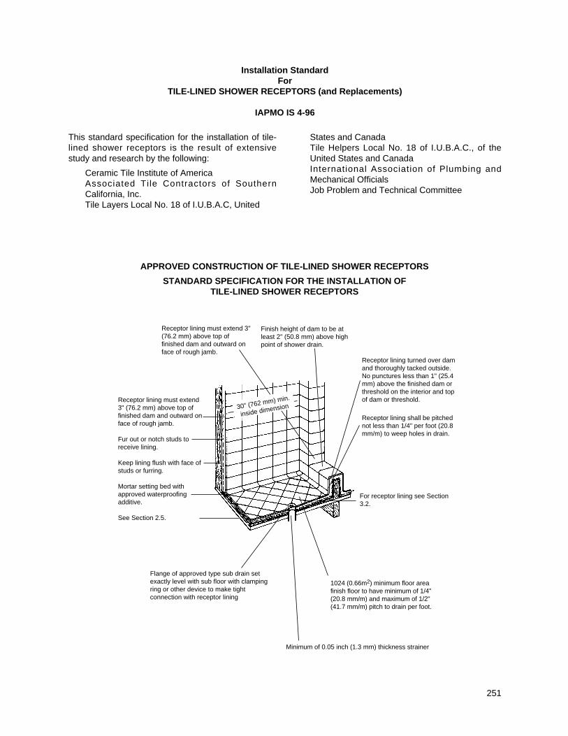
This standard specification for the installation of tile-lined shower receptors is the result of extensivestudy and research by the following:
Ceramic Tile Institute of AmericaAssociated Tile Contractors of SouthernCalifornia, Inc.Tile Layers Local No. 18 of I.U.B.A.C, United
States and CanadaTile Helpers Local No. 18 of I.U.B.A.C., of theUnited States and CanadaInternational Association of Plumbing andMechanical OfficialsJob Problem and Technical Committee
251
Installation StandardFor
TILE-LINED SHOWER RECEPTORS (and Replacements)
IAPMO IS 4-96
APPROVED CONSTRUCTION OF TILE-LINED SHOWER RECEPTORS
STANDARD SPECIFICATION FOR THE INSTALLATION OF TILE-LINED SHOWER RECEPTORS
Finish height of dam to be atleast 2" (50.8 mm) above highpoint of shower drain.
Receptor lining must extend 3"(76.2 mm) above top offinished dam and outward onface of rough jamb.
Receptor lining must extend3" (76.2 mm) above top offinished dam and outward onface of rough jamb.
Fur out or notch studs toreceive lining.
Keep lining flush with face ofstuds or furring.
Mortar setting bed withapproved waterproofingadditive.
See Section 2.5.
Flange of approved type sub drain setexactly level with sub floor with clampingring or other device to make tightconnection with receptor lining
Minimum of 0.05 inch (1.3 mm) thickness strainer
Receptor lining turned over damand thoroughly tacked outside.No punctures less than 1" (25.4mm) above the finished dam orthreshold on the interior and topof dam or threshold.
Receptor lining shall be pitchednot less than 1/4" per foot (20.8mm/m) to weep holes in drain.
For receptor lining see Section3.2.
1024 (0.66m2) minimum floor areafinish floor to have minimum of 1/4"(20.8 mm/m) and maximum of 1/2"(41.7 mm/m) pitch to drain per foot.
30" (762 mm) min.
inside dimension
1. General
1.1 Inspection of Work – All surfaces preparedby others shall be inspected by the tileinstaller before starting tile work and allunsatisfactory conditions reported to theAdministrative Authority. Starting tile work bythe tile installer shall be considered asacceptance of surfaces prepared by others.
1.2 Surface – All surfaces to receive tile workshall be clean, structurally sound, and conformin every way to the local building code.(Note: No tile work shall proceed until thepan and drain construction has beeninspected and approved by theAdministrative Authority, where required.)
2. Materials
2.1 Tile Quality and Grade – Tile shall complywith American National StandardSpecification for Ceramic Tile, A137.1(equivalent to and incorporating U.S. Dept.of Commerce Simplif ied PracticeRecommendation, R61-61 and FederalSpecification SS-T-308b, Tile, Floor, Wall,and Trim Units, Ceramic), or CTI 69.5.
2.2 Cement – Cement shall be portland cementtype I or type II, conforming to ASTM C-150.
2.3 Sand – Sand shall be damp, clean andgraded ASTM C-144.
2.4 Water – Water shall be potable.2.5 Reinforcing shall be 2.5 lbs. per sq. yard
(1.1 kg per m2) or greater galvanized metallath conforming to ANSI A42.3 or 2 inches x2 inches (51 mm x 51 mm), 16/16 gage or 3inches x 3 inches (76 mm x 76 mm) mesh,13 x 13 gage or 1-1/2 inches x 2 inches (38mm x 51 mm) mesh, 16 x 13 gage steel, wireconforming to ASTM A82 and A185.
2.6 Asphalt shall conform to FederalSpecification SS-A-0666, Type Z, Grade 2,Class A.
2.7 Plastic Roof Cement shall conform toFederal Specifications SS-C-153.
2.8 Water Resistant Felt Membrane – Thewater resistant felt membrane shall be atleast 15 lb. (6.8 kg) asphalt saturated feltconforming to Type l, Federal SpecificationHH-F-191 (a).
2.9 Plastic Membrane shall comply withapplicable standards listed in Table 14-1 ofthe UPC.
2.10 Other Membranes – Where theAdministrative Authority approves their use,non-metallic sub-pans or linings or lead sheetsweighing not less than 4 lbs. per sq. foot(191.5 Pa) and copper pans of at least No. 24B & S gage (Brown & Sharp 0.0201 inches) orgreater in thickness may be used.
2.11 Waterproofing Admixture – The mortarbed of the receptor shall be mixed with awaterproof admixture approved by theAdministrative Authority in the amountsallowed by such approval.
CURRENTLY APPROVED MORTAR ADDITIVES
Anti-Hydro—1 qt. (0.95 I) per sack of cementPlastiment—1 lb. (0.5 kg) of powder per sackof cementPlastiment—2 oz. (56.7 g) of fluid per sackof cementSika 3A—1 qt. (0.95 I) per sack of cementSuconem (Red Label)—1 pint (0.47 I) persack of cement
3. Installation
3.1 Shower Drains – An approved type showerfloor drain with sub-drain shall be installedwith every such shower membrane. Flangeof each sub-drain shall be accurately setexactly level with sloping sub-floor and shallbe equipped with a clamping ring or otherapproved device to make a tight connectionbetween the membrane and the sub-drain.The sub-drain shall have weep holes into thewaste line. The weep holes located in thesubdrain clamping ring shall be protectedfrom becoming clogged during the placmentof finish materials. The drain shall be ofsuch design that there will be not less than2" (51 mm) depth from the top of the sub-drain flange to top of the strainer. Unlessotherwise approved by the AdministrativeAuthority, drains shall be located in theapproximate center of the shower area.
3.2 Sloping Sub-Floor and Shower Membrane– All lining materials shall be pitched onequarter (1/4) inch per foot (20.8 mm/m) toweep holes in the sub-drain by means of asmooth and solidly formed sloping sub-base.All such lining materials shall extend upwardon the side walls and rough jambs of theshower opening to a point not less thanthree (3) inches (76 mm) above the top ofthe finished dam or threshold and shallextend outward over the top of the roughthreshold and be turned over and fastenedon the outside face of both the roughthreshold and the jambs.
3.2.1 Non-metallic shower sub-pans or linings maybe built-up on the job site of not less thanthree (3) layers of standard grade fifteen (15)pound (6.8 kg) asphalt impregnated roofingfelt. The bottom layer shall be fitted to the
UNIFORM PLUMBING CODE
252
IS 4
formed sub-base and each succeeding layerthoroughly hot-mopped to that below, withhot asphalt conforming to Fed. Spec. SS-A0666 Type Z, Grade 2, Class A on thebasis of twenty (20) pounds (9.1 kg) ofasphalt per layer per square. All cornersshall be carefully fitted and shall be madestrong and water-tight by folding or lapping,and each corner shall be reinforced withsuitable webbing hot-mopped in place. Allfolds, laps and reinforcing webbing shallextend at least four (4) inches (102 mm) inall directions from the corner and all webbingshall be of approved type and mesh,producing a tensile strength of not less thanfifty (50) pounds per square inch (344.5 kPaper square meter) in either direction.
3.2.2 Non-metallic shower sub-pans or linings mayalso consist of single or multi-layers of otherapproved equivalent materials, suitablyreinforced and carefully fitted in place on thejob site, as elsewhere required in this sectionaccording to manufacturer's recommendedinstallation procedures.Where flexible plastic sheet membranes areused, corners shall be carefully constructedby folding or bonding of prefabricatedreinforcing corner. Joints in flexible plasticsheeting shall be constructed with theappropriate solvent bonding liquid, bodiedsolvent cement or thermal welding.
3.2.3 Where lead and copper pans are used asmembranes, the installation shall be made insimilar manner as required for feltmembranes except the asphalt moppings,and in addition the pans shall be insulatedfrom all concrete and mortar surfaces andfrom all conducting substances other thantheir connecting drain by 15 lb. (6.8 kg)asphalt saturated felt or an approvedequivalent hot mopped to the lead or copperpan. Joints in lead and copper pans shall notbe soldered, but shall be burned or silverbrazed respectively.
3.2.4 All linings shall be properly recessed andfastened to approved backing so as not tooccupy the space required for the wallcovering and shall not be nailed orperforated at any point which will be lessthan one (1) inch (25.4 mm) above thefinished dam or threshold.
3.3 Tests – Upon installation, all linings shall betested for water tightness by being filled tothe top of the rough threshold with water fora period of time sufficient to establish theirwater tightness. (Usually twenty-four (24)
hours with no loss of water. See the localAdministrative Authority for exact time limit.)A test plug shall be so placed that both theupper and under sides of the lining shall besubjected to test at its point of contact withthe sub-drain. When the test plug isremoved, all of the test water shall drain outby gravity through the weep holes. A ring ofnon-absorbent material must be placedaround the weep holes to keep them openwhen the finish materials are installed.
3.4 Receptor – Shower floor shall be of ceramictile set in portland cement mortar mixed inthe proportion of one (1) part portlandcement to four (4) parts of mortar sand byvolume and shall be provided with anapproved shower drain designed to make awater-tight joint at the floor. The mortarmixture shall be of such consistency that atroweled surface readily assumes a smoothscreeded surface. All concrete mortar basesshall be mixed with an approvedwaterproofing admixture and properlyreinforced with 2.5 lbs. per square yard (1.1kg per square m) or more galvanized metallath or 2 inches x 2 inches (51 mm x 51mm), 16/16 gage or 3 inches x 3 inches (76mm x 76 mm) mesh, 13 x 13 gage or 1-1/2inches x 2 inches (38 mm x 51 mm) mesh,16 x 13 gage cold drawn welded steel wirefabric located in the approximate center ofthe mortar bed and extending at least 3inches (76 mm) at any point. The finishedfloor shall be not less than 2 inches (51 mm)measured from the top surface of themembrane. The high point of the tile floorshall be not less than 2 inches (51 mm) ormore than 9 inches (229 mm) below the topof the f inished dam and shall have aminimum of 1/4 inch (6.4 mm/m) and amaximum of 1/2 inch (19.1 mm/m) pitch perfoot toward the drain. Shower walls to aminimum height of 3 inch (76 mm) and notless than 1 inch (25.4 mm) above thefinished dam shall be lined with ceramic tileset in portland cement mortar.Exception: Special use showercompartments for wheelchair use mayeliminate the curb or threshold. The requiredslope and depth shall be maintained fromthe door or entry to the drain opening.The minimum distance between the door orentry to the drain opening shall be 4 feet(1219 mm).
3.5 Floors of public shower rooms shall have anon-skid surface and shall be drained in
TILE-LINED SHOWER RECEPTORS IS 4
253
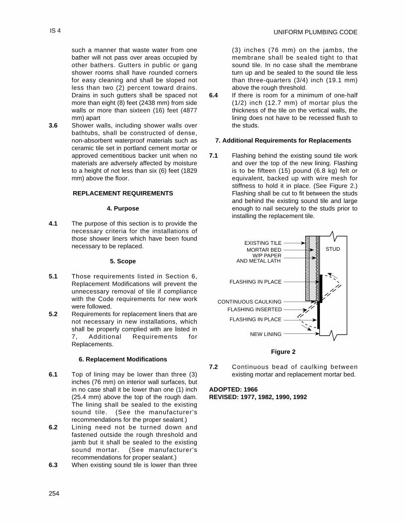
UNIFORM PLUMBING CODE
254
such a manner that waste water from onebather will not pass over areas occupied byother bathers. Gutters in public or gangshower rooms shall have rounded cornersfor easy cleaning and shall be sloped notless than two (2) percent toward drains.Drains in such gutters shall be spaced notmore than eight (8) feet (2438 mm) from sidewalls or more than sixteen (16) feet (4877mm) apart
3.6 Shower walls, including shower walls overbathtubs, shall be constructed of dense,non-absorbent waterproof materials such asceramic tile set in portland cement mortar orapproved cementitious backer unit when nomaterials are adversely affected by moistureto a height of not less than six (6) feet (1829mm) above the floor.
REPLACEMENT REQUIREMENTS
4. Purpose
4.1 The purpose of this section is to provide thenecessary criteria for the installations ofthose shower liners which have been foundnecessary to be replaced.
5. Scope
5.1 Those requirements listed in Section 6,Replacement Modifications will prevent theunnecessary removal of tile if compliancewith the Code requirements for new workwere followed.
5.2 Requirements for replacement liners that arenot necessary in new installations, whichshall be properly complied with are listed in7, Addit ional Requirements forReplacements.
6. Replacement Modifications
6.1 Top of lining may be lower than three (3)inches (76 mm) on interior wall surfaces, butin no case shall it be lower than one (1) inch(25.4 mm) above the top of the rough dam.The lining shall be sealed to the existingsound ti le. (See the manufacturer'srecommendations for the proper sealant.)
6.2 Lining need not be turned down andfastened outside the rough threshold andjamb but it shall be sealed to the existingsound mortar. (See manufacturer'srecommendations for proper sealant.)
6.3 When existing sound tile is lower than three
(3) inches (76 mm) on the jambs, themembrane shall be sealed tight to thatsound tile. In no case shall the membraneturn up and be sealed to the sound tile lessthan three-quarters (3/4) inch (19.1 mm)above the rough threshold.
6.4 If there is room for a minimum of one-half(1/2) inch (12.7 mm) of mortar plus thethickness of the tile on the vertical walls, thelining does not have to be recessed flush tothe studs.
7. Additional Requirements for Replacements
7.1 Flashing behind the existing sound tile workand over the top of the new lining. Flashingis to be fifteen (15) pound (6.8 kg) felt orequivalent, backed up with wire mesh forstiffness to hold it in place. (See Figure 2.)Flashing shall be cut to fit between the studsand behind the existing sound tile and largeenough to nail securely to the studs prior toinstalling the replacement tile.
Figure 2
7.2 Continuous bead of caulking betweenexisting mortar and replacement mortar bed.
ADOPTED: 1966REVISED: 1977, 1982, 1990, 1992
EXISTING TILEMORTAR BED
W/P PAPERAND METAL LATH
FLASHING IN PLACE
CONTINUOUS CAULKING
FLASHING INSERTED
FLASHING IN PLACE
NEW LINING
STUD
IS 4
This installation standard shall apply to ABSbuilding drain, waste and vent systems as governedby the Uniform Plumbing Code. Material StandardASTM D2661-97, “Standard Specification ofAcrylonitrile-Butadiene-Styrene (ABS) Plastic Drain,Waste and Vent Pipe and Fittings,” or ASTM F628-97,“Acrylonitrile-Butadiene-Styrene (ABS) Schedule 40Plastic, Drain, Waste and Vent Pipe with a CellularCore,” shall form a part of this standard.
Installation, material and inspection shall complywith the current edition of the Uniform PlumbingCode as published by the International Association ofPlumbing and Mechanical Officials and shall alsocomply with this standard.
Note: The Building Official shall be consulted aboutpenetration of fire separations, height and area orother limitations.
Note: The following sections of the UniformPlumbing Code apply.
202.0 Definition ABSTable 14-1 Pipe and Fittings
ASTM D2661-97 D3311-94*ASTM D2122-97 F402-93ASTM F628-97
301.1 Minimum Standards704.4 Closet Flanges707.1 Cleanout Fittings311.8 Fittings Screwed310.0 Workmanship311.0 Prohibited Fittings and Practices
101.4.1.1 Repair and Alterations313.0 Protection of Piping, Materials and
Structures314.0 Hangers and Supports (Vertical Piping)314.0 Hangers and Supports (Horizontal
Piping)103.5 Inspection723.0 Testing701.0 Materials (Drainage)903.0 Materials (Venting)903.4 Straining or Bending Pipe
1003.0 Traps Described316.1.1 Threaded Joints316.1.6 Type of Joints – Solvent Cement Plastic
Pipe Joints316.2.3 Special Joints316.3.1 Flanged Fixture Connections
316.4 Prohibited Joints and Connections
317.0 Increasers and Reducers1101.3 Materials Uses
ABBREVIATIONSASTM American Society for Testing and MaterialsIAPMO International Association of Plumbing and
Mechanical OfficialsUPC Uniform Plumbing Code
301.1 Minimum Standards301.1.1 Pipe
ABS pipe is furnished in straight lengths.The pipe is black in color. The pipe wall isthe same thickness as that of Schedule40 (IPS) standard steel pipe.Pipe shall be marked on two sides, 180°apart or spirally, in letters not less than3/16 inch (4.8 mm) high in a contrastingcolor and shall contain at least thefollowing, at not more than two (2) feet(610 mm) intervals:(a) Manufacturer’s name or trademark;(b) ASTM designation;(c) Nominal pipe size;(d) Symbol ABS-DWV or COEX ABS
FOAMED CORE DWV;(e) Products listed by IAPMO that are
covered by this standard shall belabeled with the designated IAPMOcertification mark;
(f) Manufacturer’s code; and(g) Any other marking required or
permitted by law.301.1.2 Fittings
Fittings are black. Refer to Tables inASTM D2661-97 and D3311-94 fordimensions and tolerances for pipe, fittingsockets and laying lengths.Fittings shall be marked on the body orhub on both sides. The markings shallconsist of at least the following:(a) Manufacturer’s name or trademark;(b) Symbol ABS-DWV;(c) Products listed by IAPMO that are
covered by this Standard shall belabeled with the designated IAPMOcertification mark; and
(d) Any other markings required orpermitted by law.
255
Installation StandardFor
ABS BUILDING DRAIN, WASTE AND VENT PIPE AND FITTINGS
IAPMO IS 5-92e1
*Although referenced in this standard, some of the fittings shown in the standard are not acceptable under the Uniform Plumbing Code.
301.1.3 Solvent CementSolvent cement shall be as specified inASTM Standard D2235-96a. Solventcement labels shall contain at least thefollowing:(a) Manufacturer’s or supplier’s name
and address, tradename, trademarkor both;
(b) Cement for ABS (pipe and fittings);(c) ASTM designation D2235;(d) Lot number;(e) Recommended procedure for use and
safety precautions;(f) Products listed by IAPMO that are
covered by this Standard shall belabeled with the designated IAPMOcertification mark; and
(g) Any other markings required orpermitted by law.
310.0 Workmanship310.1 Alignment
All piping system components shall bealigned properly without strain. Pipe shallnot be bent or pulled into posit ion.Vertical piping shall be maintained inalignment between floors with midstoryguides. Pipe and fitt ings shall be sopositioned that identifying markings shallbe readily visible for inspection.
313.0 Protection of Piping313.1 Storage
Pipe and fittings should not be stored indirect sunlight. However, exposure todirect sunlight during normal constructionperiods is not considered harmful. Pipeshall be stored in such a manner as toprevent sagging or bending.
313.2 Expansion And ContractionThermal expansion and contraction ofplastic drain waste and vent systems shallbe taken into consideration. Thermalexpansion and contraction may becontrolled by several methods: offset,expansion joints or restraints. Regardlessof method utilized, certain conditions shallbe met.(a) Support, but do not rigidly restrain
piping at changes of direction.(b) Do not anchor pipe rigidly in walls.(c) Holes through framing members must
be adequately sized to allow for freemovement.
DWV installations with frequent changesin direction will compensate for thermal
expansion and contraction. Expansionjoints may be utilized in vertical straightruns in excess of thirty (30) feet (9144mm) provided they are installed permanufacturer’s installation instructions.Except piping buried below ground,horizontal and vertical piping should beinstalled with restraint f i t t ings or aminimum twenty-four (24) inches (610mm) 45° offset every thirty (30) feet (9144mm).Thermal expansion for installationssubject to temperature changes may bedetermined from Table 3-1. The linearexpansion shown is independent of thediameter of the pipe.
313.3 Exposed PipingPiping shall not be exposed to directsunlight. Exception: Vent piping throughroof. Plumbing vents through roof,exposed to sunlight shall be protected bywater base synthetic latex paints.Adequate support shall be provided whereABS piping is exposed to wind, snow andice loading.
313.4 Protection From DamagePiping passing through wood studs orplates shall be protected from puncture bya minimum 1/16 inch (1.6 mm) thick steelplate. Piping shall be protected fromconcrete form oil.
313.5 Anti-Freeze ProtectionAnti-Freeze Protection – ABS pipe andtraps can be protected from freezing bythe use of one of the following solutions ormixtures:(a) 4 quarts (3.8 liters) of water mixed
with 5 quarts (4.8 liters) of glycerol(b) 2-1/2 lbs. (1.1 kg) of magnesium
chloride dissolved in one gallon (3.8liters) of water
(c) 3 lbs. (1.4 kg) of table salt dissolvedin one gallon (3.8 liters) of water.
The salt solutions are effective toapproximately 10°F (-12°C). If lowertemperatures are anticipated, the pipeshould be drained or the glycerol solutionshould be used.
UNIFORM PLUMBING CODE
256
IS 5
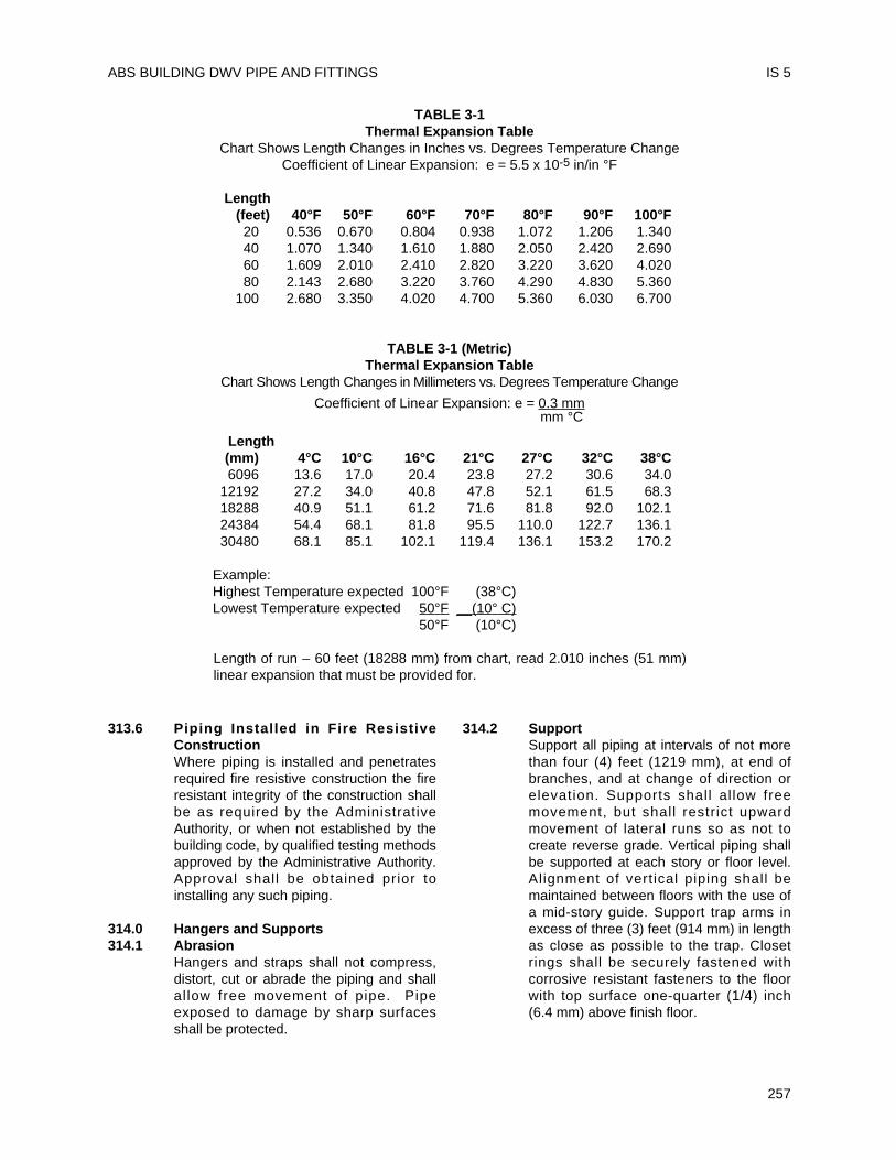
ABS BUILDING DWV PIPE AND FITTINGS
257
313.6 Piping Installed in Fire ResistiveConstructionWhere piping is installed and penetratesrequired fire resistive construction the fireresistant integrity of the construction shallbe as required by the AdministrativeAuthority, or when not established by thebuilding code, by qualified testing methodsapproved by the Administrative Authority.Approval shall be obtained prior toinstalling any such piping.
314.0 Hangers and Supports314.1 Abrasion
Hangers and straps shall not compress,distort, cut or abrade the piping and shallal low free movement of pipe. Pipeexposed to damage by sharp surfacesshall be protected.
314.2 SupportSupport all piping at intervals of not morethan four (4) feet (1219 mm), at end ofbranches, and at change of direction orelevation. Supports shall al low freemovement, but shall restrict upwardmovement of lateral runs so as not tocreate reverse grade. Vertical piping shallbe supported at each story or floor level.Alignment of vertical piping shall bemaintained between floors with the use ofa mid-story guide. Support trap arms inexcess of three (3) feet (914 mm) in lengthas close as possible to the trap. Closetrings shall be securely fastened withcorrosive resistant fasteners to the floorwith top surface one-quarter (1/4) inch(6.4 mm) above finish floor.
IS 5
TABLE 3-1Thermal Expansion Table
Chart Shows Length Changes in Inches vs. Degrees Temperature ChangeCoefficient of Linear Expansion: e = 5.5 x 10⁻⁵ in/in °F
Length(feet) 40°F 50°F 60°F 70°F 80°F 90°F 100°F20 0.536 0.670 0.804 0.938 1.072 1.206 1.34040 1.070 1.340 1.610 1.880 2.050 2.420 2.69060 1.609 2.010 2.410 2.820 3.220 3.620 4.02080 2.143 2.680 3.220 3.760 4.290 4.830 5.360
100 2.680 3.350 4.020 4.700 5.360 6.030 6.700
TABLE 3-1 (Metric)Thermal Expansion Table
Chart Shows Length Changes in Millimeters vs. Degrees Temperature Change
Coefficient of Linear Expansion: e = 0.3 mmmm °C
Length(mm) 4°C 10°C 16°C 21°C 27°C 32°C 38°C6096 13.6 17.0 20.4 23.8 27.2 30.6 34.0
12192 27.2 34.0 40.8 47.8 52.1 61.5 68.318288 40.9 51.1 61.2 71.6 81.8 92.0 102.124384 54.4 68.1 81.8 95.5 110.0 122.7 136.130480 68.1 85.1 102.1 119.4 136.1 153.2 170.2
Example:Highest Temperature expected 100°F (38°C)Lowest Temperature expected 50°F __(10° C)
50°F (10°C)
Length of run – 60 feet (18288 mm) from chart, read 2.010 inches (51 mm)linear expansion that must be provided for.
UNIFORM PLUMBING CODE
258
701.0 Materials, Drainage-Deleted
903.0 Materials, Vent-Deleted
1003.0 Traps1003.1 Connection to Metal Traps
Traps shall be connected by means oflisted threaded trap adapters.
705.0 Joints705.1 Caulked Joints
Make connections or transitions to bell-and-spigot cast iron soil pipe and fittings,and to bell-and-spigot pipe and fittings ofother materials with listed mechanicalcompression joints designed for this use,or caulked joints made in an approvedmanner. In caulking, pack the joint withoakum or hemp and fill with molten lead toa depth of not less than (1) inch (25.4mm). Allow a period of four (4) minutes forcooling, following which, caulk the lead atthe inside and outside edges of the joint.Lead shall not be overheated. Heat lead tomelting point only.Note: Caulked joints should be avoided ifpossible.
316.0 Solvent Cement Joints316.1 Selection. Solvent cement shall be
recommended for ABS by themanufacturer. Follow manufacturer’srecommendations for types of solventcement for such condit ions astemperature over 100°F (38°C), orhumidity over 60%.
316.1.1 Handling (to maintain effectiveness).Solvent cement containers no larger than1 quart (1 liter) should be used in the field(to avoid thickening due to evaporation).Keep container closed and in the shadewhen not in use. Keep applicatorsubmerged in solvent cement betweenapplications. When solvent cementbecomes thicker, THROW IT AWAY.Solvent cement shall NOT be thinned.
316.1.2 Size of Applicator. Applicator should beabout one half the pipe diameter. Do notuse small applicator on large pipes.Ordinary pure bristle paint brush orapplicators furnished with product aresatisfactory.
316.1.3 Application. Solvent cement shall beapplied deliberately, but without delay (twomen may be needed to make large joints).Use special care when temperature isover 100°F (38°C) or humidity is over60%.
316.1.5 Procedure.XI SAFETY REQUIREMENTS AND
PRECAUTIONSXI.1 General. Solvents contained in
ABS plastic pipe cements areclassif ied as airbornecontaminants and flammable andcombustible liquids. Precautionslisted in this appendix should befollowed to avoid injury topersonnel and the hazard of fire.
XI.2 Safety Precautions:XI.2.1 Prolonged breathing of solvent
vapors should be avoided. Whenpipe and fittings are being joinedin partially enclosed areas, aventilating device should be usedin such a manner to minimize theentry of vapors into the breathingareas.
XI.2.2 Solvent Cements should be keptaway from all sources of ignition,heat, sparks and open flame.
XI.2.3 Containers for solvent cementsshould be kept t ightly closedexcept when the cement is beingused.
XI.2.4 All rags and other materials usedfor mopping up spills should bekept in a safety waste receptaclewhich should be emptied daily.
XI.2.5 Most of the solvents used in ABSpipe cements can be consideredeye irritants and contact with theeye should be avoided for it maycause eye injury. Proper eyeprotection and the use ofchemical goggles or face shieldsis advisable where the possibilityof splashing exists in handlingsolvent cements. In case of eyecontact, flush with plenty of waterfor 15 minutes and call aphysician immediately.
XI.2.6 Repeated contact with the skinshould be avoided. Propergloves impervious to andunaffected by the solvents shouldbe worn when frequent contactwith the skin is likely. Applicationof the solvents or solventcements with rags and bare handis not recommended. Brushesand other suitable applicators canbe used effectively for applyingthe solvent cement, thus avoiding
IS 5
skin contact. In the event ofexcessive contact, removecontaminated clothing and washskin with soap and water.
Step 1 Cut pipe square with hand sawand miter box, mechanical cut-offsaw or tube cutter designed forplastic.
Step 2 Ream inside and chamfer outsideof pipe (to eliminate all burrs).
Step 3 Clean all dirt, moisture andgrease from pipe and socket. Usea clean, dry rag.
Step 4 Check dry fit of pipe in fitting.Pipe should enter fitting socketfrom 1/3 to 3/4 depth of socket.
Step 5 Apply a light coat of ABS solventcement to inside of socket usingstraight outward strokes (to keepexcess solvent out of socket).This is also to prevent solventcement damage to pipe. For loosefits, apply a second coat ofsolvent cement. Time is importantat this stage. See Section 316.1.3.
Step 6 While both the inside socketsurface and the outside surfaceof the pipe are SOFT and WETwith solvent cement, forcefullybottom the pipe in the socket,giving the pipe a one-quarter turn,if possible. The pipe must go tothe bottom of the socket.
Step 7 Hold the joint together until tight(partial set).
Step 8 Wipe excess cement from thepipe. A properly made joint willnormally show a bead around itsentire perimeter. Any gaps mayindicate insufficient cement or theuse of light bodied cement onlarger diameters where heavybodied cement should have beenused.
Step 9 The system shall not be testeduntil the joints have cured (set) atleast as long as recommended bythe manufacturer.
316.1.6 Threaded JointsListed adapter fittings shall be used for thetransition to threaded connections. Nothreaded female ABS fitting(s) or joint(s)shall be located in a non-accessiblelocation. The joint between the ABS pipeand adapter fitting shall be of the solventcement type.
Only listed thread tape or thread lubricant,specifically intended for use with plasticsshall be used. Conventional pipecompounds, putty, l inseed oil baseproducts and unknown mixtures shall beremoved and be replaced with newmaterials. Where a threaded joint is made,obtain t ightness by maximum handtightening plus additional tightening with astrap wrench not to exceed one full turn.
316.2.3 Special Joints316.2.3.1 Connection To Non-Plastic Pipe
When connecting plastic pipe to othertypes of piping, use only listed fittings andadapters, designed for the specif ictransition intended.
316.4 Prohibited Fittings and Connections(a) Drainage system – Any fitt ing or
connection which has anenlargement, chamber or recess witha ledge, shoulder or reduction of pipearea, that offers an obstruction to flowthrough the drain is prohibited.
(b) No fitting or connection that offersabnormal obstruction to flow shall beused. The enlargement of a three (3)inch (76 mm) closet bend or stub tofour (4) inches (102 mm) shall not beconsidered an obstruction.
ADOPTED: 1966REVISED: 1971, 1974, 1975, 1976, 1977, 1981,
1982, 1983, 1987, 1989, 1990, 1992
ABS BUILDING DWV PIPE AND FITTINGS IS 5
259

UNIFORM PLUMBING CODE
260
This installation standard is for use with IAPMO-listed systems of hubless cast iron soil pipe andfittings, utilizing IAPMO-listed couplings.
This standard shall serve to supplement anyexisting applicable standards and requirements ofappropriate codes and laws regulating use ofhubless cast iron soil pipe and fittings in buildingsewer, drainage, waste, vent, and rainwater systems,and to provide the necessary requirements forinstallation, use and inspection of piping and fittingsfor this purpose. This system may be used in anylocation where cast iron soil pipe is acceptable underthe Uniform Plumbing Code.
The provisions of this standard are not intendedto prevent the use of any alternate material ormethod of construction, provided it meets therequirements of the standard.
Note: The following sections of the UniformPlumbing Code apply to this standard:
301.1 Minimum Standards (Material)704.4 Closet Flanges
Table 14-1 Plumbing Material Standards310.0 Workmanship311.0 Prohibited f i tt ings and
practices101.4.1.1 Repair and alterations
313.0 Protection of piping materialsand structures
314.0 Hangers and SupportsTable 3-1
712.2 and 712.3 Testing701.0 Materials (Drainage)
Table 7-3 SizingTable 7-5 Sizing
707.14 Cleanout Plugs903.0 Materials (Venting)
1003.0 Traps Described705.1 Type of joints
705.3.2 Expansion Joints316.4 Prohibited joints and
connections317.0 Increasers and reducers
Chapter 11 Storm Drainage1101.3 Materials Uses
1101.11 Roof Drainage
301.1 Minimum StandardsHubless pipe, fittings and couplings shall
be manufactured in strict compliance withappropriate standards acceptable toIAPMO.
301.1.1 All hubless system components shall beclearly marked with the following:(a) Manufacturer’s name or trademark;(b) Products listed by IAPMO that are
covered by this standard shall belabeled with the designated IAPMOcertification mark;
(c) Country of origin; and(d) Any other markings required by law.
301.1.1.1 Pipe shall be legibly and continuouslymarked along the full length of the barrel.
301.1.1.2 All installations shall be made so that thecomponents can be readily identified.When laying hubless pipe in a ditch, theidentification shall be on the top side ofthe pipe. When in walls, the identificationshall be on a side readily visible to theinspector.
301.1.1.3 Markings on fittings shall be located aminimum 1-1/2" (38 mm) from any endwhere a coupling may be attached forsizes through 4" (102 mm) and a minimumof 2" (51 mm) for larger sizes. With theexception of the closet bends, fittings areusually provided with a small positioninglug. When properly positioned, the gasketin other than wider body couplings will restagainst but will not cover the lug. Gasketsfor wider body couplings will cover the lug.
310.0 WorkmanshipAll piping systems shall be installed andsupported in a workmanlike manner.
314.0 Hangers and SupportsSupport and stability of all components ofa hubless cast iron sanitary and rainwatersystem shall be given prime consideration.
314.1 Vertical hubless systems shall besupported per Table 3-1 of the UniformPlumbing Code.
314.2 Horizontal hubless systems shall besupported per Table 3-1 of the UniformPlumbing Code. Supports shall beadequate to maintain alignment andprevent sagging and shall be placed withineighteen (18) inches (457 mm) of the joint.
261
Installation StandardFor
HUBLESS CAST IRON SANITARY AND RAINWATER SYSTEMS
IAPMO IS 6-95
314.2.1 Joints shall be supported at least at everyother joint except that when the developedlength between supports exceeds four (4)feet (1219 mm) they shall be provided ateach joint. Supports shall also beprovided at each horizontal branchconnection. Such support shall be placedimmediately adjacent to the coupling.
314.2.2 Suspended lines shall be suitably bracedto prevent horizontal movement.
314.2.3 Closet bends, trap arms and similarbranches shall be secured againstmovement in any direction.
314.3 Hubless systems, in the ground shall belaid on a firm bed for its entire lengthexcept where support is otherwiseprovided which is adequate in thejudgement of the Administrative Authority.Vertical sections and their connectingbranches shall be adequately staked andfastened to driven steel pipe or reinforcingbars so as to remain stable while backfillis placed or concrete is poured.
705.1 JointsDuring installation assembly, hubless pipeand fittings shall be inserted into thegasket and firmly seated against a centerstop. Center stop ring or fittings shall notcreate an enlargement chamber or recesswith a ledge, shoulder or reduction of pipearea or offer an obstruction to flow. Inorder to provide a sound joint with field cutlengths of pipe, the ends shall be cutsquare. Clamping assemblies shall beproperly posit ioned and uniformlytightened to the torque required by IAPMOlisting. The use of an adequate torquewrench recommended by themanufacturer of the clamping assembliesshall be used. The use of adhesives,lubricants, sealants, etc., or the addition ofany substance between the pipe and thecoupling shall be prohibited.
705.1.1 IAPMO-listed adapters designed for thespecific transition intended shall be usedfor the intermembering of materials.
705.1.2 The connection of closet rings, floor andshower drains and similar "slip over" fittingsto hubless pipe and fittings and theconnection of hubless pipe and fittings toconventional soil pipe hubs shall beaccomplished by the use of caulked leadjoints, or other connections listed by IAPMO.
ADOPTED: 1966REVISED: 1972, 1974, 1975, 1982, 1989, 1991,1993
UNIFORM PLUMBING CODE
262
IS 6
This standard shall govern the installation ofpolyethylene (PE) cold water building supply andyard piping. (See Section 604.1 of the UniformPlumbing Code and Section 609.2 of this standardfor allowable location and pressure). Installation,material and inspection shall comply with the currentedition of the Uniform Plumbing Code published bythe International Association of Plumbing andMechanical Officials, and shall also comply with thisstandard.
Note: The following sections of the UniformPlumbing Code apply to polyethylene piping.
202.0 Definition of PETable 14-1 Fittings (and fasteners) for joining PE
pipe IAPMO PS25-84Plastic insert fittings for Polyethylene(PE) Plastic Pipe
ASTM D2609-96aPE Pipe ASTM D2239-96a
310.0 Workmanship313.0 Protection of Piping, Materials and
Structures314.0 Supporting in the Ground315.0 Backfilling
316.2.3 Connection to other materialsChapter 6 Water Distribution
604.1 Location609.1 Depth of piping609.3
103.5.4.2 & 103.5.3.3 Testing
Chapter 2 DEFINITIONSChapter 14
ASTM American Society for Testing andMaterials
IAPMO International Association of Plumbingand Mechanical Officials
NSF National Sanitation FoundationPS Material and Property Standard
published by IAPMOUPC Uniform Plumbing Code published by
IAPMO
301.1 Minimum Standards301.1.1 Material. Material shall conform to the
appropriate standard in Table 14-1. Seenote ahead of Chapter 2 of this standard.
301.1.1.1 Pipe. PE pipe is plastic and black.
301.1.1.2 Fittings. Fittings are copper alloy ornylon barbed insert fittings.
301.1.2 Markings301.1.2.1 Piping. Pipe shall be marked at intervals
of not more than five (5) feet (1524 mm)with at least the following:(a) Manufacturer’s name or trademark;(b) ASTM D2239;(c) Pipe size;(d) PE 3406 or PE 3408;(e) Pressure rating of SDR 7 - PE 3406
(160 psi/1.10 mPa) and PE 3408 (200psi/1.38 mPa);
(f) NSF seal or marking of otheracceptable agency; and
(g) Pipe listed by IAPMO that is coveredby this standard shall be labeled withthe UPC logo to show compliancewith this standard.
301.1.2.2 Fittings. Fittings shall be marked with atleast the following:(a) Manufacturer’s name or trademark;(b) Size; and(c) Fittings listed by IAPMO that are
covered by this standard shall belabeled with the UPC logo to showcompliance with this standard.
301.1.2.3 Bands. Bands shall be marked with atleast the following:(a) Manufacturer’s name or trademark;(b) Model;(c) Stainless steel, Series 300; and(d) Bands l isted by IAPMO that are
covered by this standard shall belabeled with the UPC logo to showcompliance with this standard.
301.1.3 Position of Markings. The identifyingmarkings on pipe, and fittings shall bevisible for inspection without movingmaterials.
313.0 Protection of Piping313.1 Storage. Unprotected pipe should not be
stored in direct sunlight. The pipe shall bestored in a way to protect it from mechanicaldamage (slitting, puncturing, etc.).
313.2 Thermal Expansion. The pipe shall besnaked in the trench bottom with enoughslack to provide for thermal expansion andcontraction. The normal slack created by
263
Installation StandardFor
POLYETHYLENE (PE) COLD WATER BUILDING SUPPLY AND YARD PIPING
IAPMO IS 7-90e1
residual coiling is generally sufficient forthis purpose. If, however, the pipe hasbeen allowed to straighten before it isplaced in the trench, six (6) inches (152mm) per one hundred (100) feet (30480mm) of length shall be allowed for thispurpose.
313.3 Exposed Piping. Vertical piping mayextend a maximum of twenty-four (24)inches (610 mm) above grade whenlocated on the exterior of the building orstructure and protected from mechanicaldamage to the satisfaction of theAdministrative Authority. Where exposedto sunlight the pipe shall be wrapped withat least 0.040 in. (1.02 mm) of tape.
315.0 Trenching and Cover315.1 Trench bottoms shall be uniformly graded
and shall be of either undisturbed soil orshall consist of a layer or layers ofcompacted backfi l l so that minimumsettlement will take place.
316.1 Joints316.1.1 Procedure. Polyethylene pipe joints shall
be made as follows (see Section 301.1.1):Step 1. Pipe shall be cut square, using a
cutter designed for plastic pipe,and chamfer ends to removesharp edges.
Step 2. Place two strap-type stainlesssteel bands over the pipe.
Step 3. Check that fittings are properlysized for pipe, as tubing fittingsare not of proper size.
Step 4. Force the end of the pipe over thebarbed insert fittings, makingcontact with the fitting shoulder(the end of the pipe may besoftened by placing in hot water).
Step 5. Position the clamps 180° apartand tighten evenly, so as to makea leak-proof joint.
316.1.2 Other Joints. Polyethylene pipe shall notbe threaded. Joints made with adhesivesor “solvent cementing” techniques areprohibited.
604.0 Materials604.1 Location. Polyethylene piping shall be
installed only outside the foundation ofany building or structure or parts thereof. Itshall be buried in the ground for its entirelength except vertical piping may beextended above grade per Section 313.3.
It shall not be installed within or under anybuilding or structure or mobile home orcommercial coach or parts thereof. Theterm "building or structure or parts thereof"shall include structures such as porchesand steps, whether covered or uncovered,roofed porte-cocheres, roofed patios,carports, covered walks, covereddriveways and similar structures orappurtenances.
604.2 Harmful Materials. Polyethylene that hasbeen in contact with gasoline, lubricatingoil or aromatic compounds, shall not beinstalled.
609.0 Installation609.1 Pipe. Kinked pipe shall not be used. PE
pipe shall not be flared.609.2 Fittings. Compression type couplings
and fitt ings shall be used only wheninstalling one and one-half (1-1/2) inch (38mm) and larger pipe. Stiffeners thatextend beyond the clamp or nut shall notbe used.
609.3 Bends. Changes in direction may bemade by bends. The installed radius ofpipe curvature shall be not less than thirty(30) pipe diameters, or the coil radius whenbending with the coil. Coiled pipe shall notbe bent beyond straight. Bends shall not bepermitted closer than ten (10) pipediameters of any fitting or valve.
609.4 Maximum Working Pressure. Workingpressure shall not exceed 160 psi (1.10mPa).
609.5 Identification. A label shall be fastenedto the main electric meter panel stating“This structure has a non-metallic waterservice”.
610.0 Sizing610.1 Piping shall be sized in accordance with
UPC Section 610.0. When UPC AppendixA is applicable, use UPC Chart A-4(Copper Tubing Type L). Flow velocityshall not exceed 8 fps (2.4 m/s).
ADOPTED:1968REVISED: 1969, 1971, 1972, 1973, 1975, 1978,1981, 1982, 1983, 1989, 1990
UNIFORM PLUMBING CODE
264
IS 7
This standard shall govern the installation of PVCpiping (with solvent cemented or elastomericgasketed joints) in cold water building supply andyard piping. (See Section 604.1 and 609.1.2 forallowable location and pressure.) Installation,material and inspection shall comply with the currentedition of the Uniform Plumbing Code published bythe International Association of Plumbing andMechanical Officials, and shall also comply with thisstandard.
Note: The following sections of the UniformPlumbing Code apply to PVC water piping.
202.0 Definition of PVCTable 14-1 Materials
310.0 Workmanship313.0 Protection of Piping, Materials and
Structures314.0 Supporting in the Ground315.0 Backfilling
316.1.6 Solvent-Cement Plastic Pipe Joints606.2.2 Use of Joints316.2.3 Plastic Pipe to Other Materials
Chapter 6 Water Distribution604.1 Location609.0 Depth of Piping
Chapter 2 DEFINITIONSChapter 14
ASTM American Society for testing andMaterials
IAPMO International Association of Plumbingand Mechanical Officials
NSF National Sanitation FoundationUPC Uniform Plumbing Code published by
IAPMO
301.1 Minimum Standards301.1.1 Material. Materials shall conform to the
appropriate standard in Table 14-1 ofthe Uniform Plumbing Code. See noteahead of Chapter 2 of this standard.
APPLICABLE STANDARDS
Type of PVC for Pipe and Fittings ASTM StandardPVC 1120 or 1220 D1784-97
PipeBell-End Poly (vinyl chloride) PVC Pipe D2672-96aPVC Schedule 40 D1785-96bPVC Schedule 80 D1785-96bPVC 160 psi (1102.4 kPa) (SDR 26)PVC 200 psi (1378 kPa) (SDR 21)PVC 250 psi (1722.5 kPa) (SDR 17)PVC 315 psi (2170.4 kPa) (SDR 13.5) D2241-93
FittingsSchedule 40 (Socket) D2466-94Schedule 80 (Socket) D2467-94Schedule 80 (Threaded) D2464-96a
Solvent CementPVC Solvent Cement D2564-93
PrimersPVC Primers F656-93
301.1.1.1 Pipe and Fittings. Pipe and fittings aremanufactured from PVC plastic.
301.1.2 Markings301.1.2.1 Pipe. Pipe shall be marked at intervals
of not more than five (5) feet (1524 mm)with at least the following:(a) Manufacturer’s name or trademark;(b) ASTM D1785 or D2241;(c) In addition, bell end pipe, PVC,
shall be marked D2672;(d) Pipe Size;(e) PVC 1120 or PVC 1220;(f) Schedule 40 or Schedule 80, SDR
or pressure rating on SDR pipe;(g) NSF seal or marking of other
acceptable agency; and(h) Pipe l isted by IAPMO that is
covered by this standard shall belabeled with the designated IAPMOcertif ication mark to showcompliance with this standard.
301.1.2.2 Fittings. Fittings shall be marked withat least the following:(a) Manufacturer’s name or trademark;(b) Size*;(c) ASTM D2464, D2466 or D2467;(d) PVC 1 or PVC 12;(e) Schedule 40 or Schedule 80;(f) NSF seal or marking of other
acceptable agency; and
265
Installation StandardFor
PVC COLD WATER BUILDING SUPPLY AND YARD PIPING
IAPMO IS 8-95e1
(g) Fittings listed by IAPMO that arecovered by this standard shall belabeled with the designated IAPMOcertif ication mark to showcompliance with this standard.
*Note: Size and material designationmay be omitted on smaller fittings.
301.1.2.3 Solvent Cement301.1.2.3.1 Markings. Solvent Cement containers
shall be marked with at least thefollowing:(a) ASTM D2564;(b) NSF Seal or marking of other
acceptable agency; and(c) Solvent cement listed by IAPMO
that is covered by this standardshall be labeled with the designatedIAPMO certification mark to showcompliance with this standard.
301.1.2.3.2 Color. Solvent Cement shall not bepurple in color.
301.1.2.4 Primers301.1.2.4.1 Markings. Primer containers shall be
marked at least the following:(a) ASTM F656;(b) NSF seal or marking of other
acceptable agency; and(c) Primer l isted by IAPMO that is
covered by this standard shall belabeled with the designated IAPMOcertif ication mark to showcompliance with this standard.
301.1.2.4.2 Color. Primer shall be purple.301.1.3 Position of Markings. The identifying
markings on pipe and fittings shall bevisible for inspection without movingmaterials.
313.0 Protection of Piping313.1 Storage. Unprotected pipe should not
be stored in direct sunlight. The pipeshall be stored in a way to protect it frommechanical damage (slitting, puncturing,etc.). Exposure to sunlight during normalconstruction periods is not harmful.PVC solvent cements should be storedin a cool place, except when actually inuse at the job site. The solvent cementmanufacturer’s specif ic storagerecommendations should be followed.
313.2 Alignment. Pipe and fittings shall bealigned properly without strain.
313.3 Thermal Expansion. Pipe (except pipewith elastomeric gasketed joints) shallbe “snaked” in the trench bottom withenough slack, at least 6 inches (152.4
mm) per 100 feet (30480 mm), tocompensate for thermal expansion andcontraction before stabilizing piping.Stabil ize piping by bringing itapproximately to operating temperaturebefore testing and backfilling by one ofthe following methods:(a) Shade backfil l. Leave all joints
exposed so that they can beexamined during pressure test.
(b) Fil l with water at operatingtemperature.
(c) Allow to stand overnight.313.4 Exposed Piping. Vertical piping may
extend a maximum of 24 in. (610 mm)above grade when located on theexterior of the building or structure andprotected from mechanical damage tothe satisfaction of the AdministrativeAuthority. Where exposed to sunlightthe pipe shall be wrapped with at least0.040 in. (1.0 mm) of tape.
315.0 Trenching, Cover and Backfill315.1 Trenching and Cover. Trench bottoms
shall be uniformly graded and shall beof either undisturbed soil or shall consistof a layer or layers of compacted backfillso that minimum settlement will takeplace.
315.2 Backfill. Selected backfill shall beused. Tamp the backfill that is placedaround the pipe so as to provide firmcontinuous support and propercompaction. Backfill at least 12 inches(305 mm) over pipes, except that jointsshall be left exposed. After inspectionand pressure test, complete backfill.
315.2.1 Elastomeric Joints . Backfi l limmediately after installing pipe.Note: This is to maintain equal spaceswithin the joints for contraction andexpansion.
316.1 Joints316.1.1 Solvent Cement Joints316.1.1.1 Selection. Follow manufacturer’s
recommendations for types of solventcement for such conditions astemperature over 100°F (38°C), humidityover 60% or use of Schedule 80 fittings.
316.1.1.2 Handling (to maintain effectiveness).Package solvent cement in containersno larger than 1 quart (1 liter). Keepsolvent cement can closed and in theshade when not in use. Keep applicator
UNIFORM PLUMBING CODE
266
IS 8
submerged in solvent cement betweenapplications. When solvent cementbecomes thicker, THROW IT AWAY.Solvent cement shall NOT be thinned.
316.1.1.3 Size of Applicator. Applicator shouldbe about one half the pipe diameter. Donot use small applicator on large pipes.
316.1.1.4 Primers. All solvent cement PVC jointsshall be made using a listed primer incompliance with ASTM F 656-96a and asspecified in Section 316.1.6 of the UPC.
316.1.1.5 Application. Solvent cement shall beapplied deliberately, but without delay(two men may be needed to make largejoints). Use special care whentemperature is over 100°F (38°C) orhumidity is over 60%.
316.1.1.6 ProcedureNote: Do not take SHORT CUTS.Most failures are caused by short cuts.DON’T TAKE A CHANCE.Xl. SAFETY REQUIREMENTS
AND PRE-CAUTIONS1
X1.1 General. Solvents contained inPVC plastic pipe cements areclassified as airborne contami-nants and flammable andcombustible liquids. Precautionslisted in this appendix should befollowed to avoid injury topersonnel and the hazard of fire.
X1.2 SAFETY PRECAUTIONS:X1.2.1 Prolonged breathing of solvent
vapors should be avoided. Whenpipe and fittings are being joinedin partially enclosed areas, aventilating device should beused in such a manner tominimize the entry of vapors intothe breathing areas.
X1.2.2 Solvent cements should be keptaway from all sources of ignition,heat, sparks and open flame.
X1.2.3 Containers for solvent cementsshould be kept tightly closedexcept when the cement isbeing used.
X1.2.4 All rags and other materialsused for mopping up spil lsshould be kept in a safetywaste receptacle which shouldbe emptied daily.
X1.2.5 Most of the solvents used inPVC pipe cements can beconsidered eye irritants andcontact with the eye should be
avoided for it may cause eyeinjury. Proper eye protectionand the use of chemicalgoggles or face shields isadvisable where the possibilityof splashing exists in handlingsolvent cements. In case of eyecontact, flush with plenty ofwater for 15 minutes and call aphysician immediately.
X1.2.6 Repeated contact with the skinshould be avoided. Propergloves impervious to andunaffected by the solventsshould be worn when frequentcontact with the skin is likely.Application of the solvents orsolvent cements with rags andbare hands is not recom-mended. Brushes and othersuitable applicators can be usedeffectively for applying thesolvent cement, thus avoidingskin contact. In the event ofexcessive contact, removecontaminated clothing and washskin with soap and water.CAUTION: Primers are toxic.Don’t allow them to touch skin.Suitable gloves are advised.
Step 1. Cut pipe square with hand sawand miter box, mechanical cut-off saw or tube cutter designedfor plastic.
Step 2. Ream and chamfer pipe (toeliminate sharp edges, beadsand all burrs).
Step 3. Clean all dirt, moisture andgrease from pipe and fittingsocket. Use a clean, dry rag.
Step 4. Check dry fit of pipe in fitting.Pipe should enter fitting socketfrom 1/3 to 3/4 depth of socket.
Step 5. Soften inside socket surface byapplying an aggressive primer.
Step 6. Soften mating outside surfaceof pipe to depth of socket byapplying a liberal coat of the(aggressive) primer. Be sureentire surface is softened.
Step 7. Again coat inside socketsurface with the (aggressive)primer. Then, without delay,apply solvent cement liberallyto outside of pipe. Use morethan enough to fill any gaps.
PVC COLD WATER BUILDING SUPPLY AND YARD PIPING IS 8
267
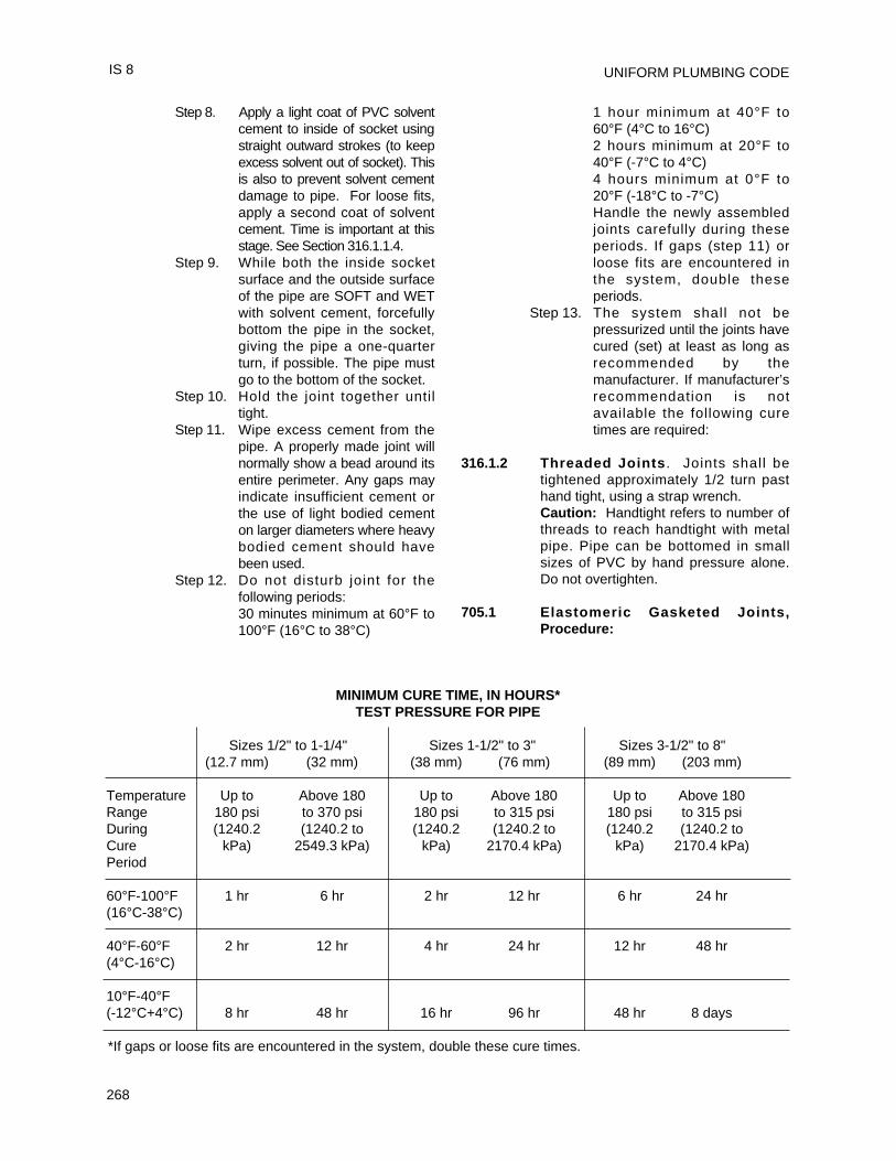
UNIFORM PLUMBING CODE
268
Step 8. Apply a light coat of PVC solventcement to inside of socket usingstraight outward strokes (to keepexcess solvent out of socket). Thisis also to prevent solvent cementdamage to pipe. For loose fits,apply a second coat of solventcement. Time is important at thisstage. See Section 316.1.1.4.
Step 9. While both the inside socketsurface and the outside surfaceof the pipe are SOFT and WETwith solvent cement, forcefullybottom the pipe in the socket,giving the pipe a one-quarterturn, if possible. The pipe mustgo to the bottom of the socket.
Step 10. Hold the joint together untiltight.
Step 11. Wipe excess cement from thepipe. A properly made joint willnormally show a bead around itsentire perimeter. Any gaps mayindicate insufficient cement orthe use of light bodied cementon larger diameters where heavybodied cement should havebeen used.
Step 12. Do not disturb joint for thefollowing periods:30 minutes minimum at 60°F to100°F (16°C to 38°C)
1 hour minimum at 40°F to60°F (4°C to 16°C)2 hours minimum at 20°F to40°F (-7°C to 4°C)4 hours minimum at 0°F to20°F (-18°C to -7°C)Handle the newly assembledjoints carefully during theseperiods. If gaps (step 11) orloose fits are encountered inthe system, double theseperiods.
Step 13. The system shall not bepressurized until the joints havecured (set) at least as long asrecommended by themanufacturer. If manufacturer’srecommendation is notavailable the following curetimes are required:
316.1.2 Threaded Joints . Joints shall betightened approximately 1/2 turn pasthand tight, using a strap wrench.Caution: Handtight refers to number ofthreads to reach handtight with metalpipe. Pipe can be bottomed in smallsizes of PVC by hand pressure alone.Do not overtighten.
705.1 Elastomeric Gasketed Joints,Procedure:
IS 8
MINIMUM CURE TIME, IN HOURS*TEST PRESSURE FOR PIPE
Sizes 1/2" to 1-1/4" Sizes 1-1/2" to 3" Sizes 3-1/2" to 8"(12.7 mm) (32 mm) (38 mm) (76 mm) (89 mm) (203 mm)
Temperature Up to Above 180 Up to Above 180 Up to Above 180Range 180 psi to 370 psi 180 psi to 315 psi 180 psi to 315 psiDuring (1240.2 (1240.2 to (1240.2 (1240.2 to (1240.2 (1240.2 toCure kPa) 2549.3 kPa) kPa) 2170.4 kPa) kPa) 2170.4 kPa)Period
60°F-100°F 1 hr 6 hr 2 hr 12 hr 6 hr 24 hr(16°C-38°C)
40°F-60°F 2 hr 12 hr 4 hr 24 hr 12 hr 48 hr(4°C-16°C)
10°F-40°F(-12°C+4°C) 8 hr 48 hr 16 hr 96 hr 48 hr 8 days
*If gaps or loose fits are encountered in the system, double these cure times.
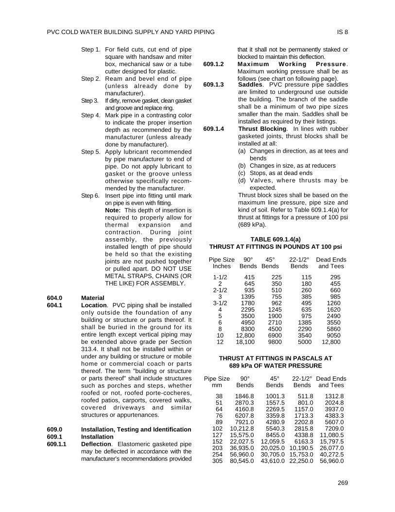
Step 1. For field cuts, cut end of pipesquare with handsaw and miterbox, mechanical saw or a tubecutter designed for plastic.
Step 2. Ream and bevel end of pipe(unless already done bymanufacturer).
Step 3. If dirty, remove gasket, clean gasketand groove and replace ring.
Step 4. Mark pipe in a contrasting colorto indicate the proper insertiondepth as recommended by themanufacturer (unless alreadydone by manufacturer).
Step 5. Apply lubricant recommendedby pipe manufacturer to end ofpipe. Do not apply lubricant togasket or the groove unlessotherwise specifically recom-mended by the manufacturer.
Step 6. Insert pipe into fitting until markon pipe is even with fitting.Note: This depth of insertion isrequired to properly allow forthermal expansion andcontraction. During jointassembly, the previouslyinstalled length of pipe shouldbe held so that the existingjoints are not pushed togetheror pulled apart. DO NOT USEMETAL STRAPS, CHAINS (ORTHE LIKE) FOR ASSEMBLY.
604.0 Material604.1 Location. PVC piping shall be installed
only outside the foundation of anybuilding or structure or parts thereof. Itshall be buried in the ground for itsentire length except vertical piping maybe extended above grade per Section313.4. It shall not be installed within orunder any building or structure or mobilehome or commercial coach or partsthereof. The term "building or structureor parts thereof" shall include structuressuch as porches and steps, whetherroofed or not, roofed porte-cocheres,roofed patios, carports, covered walks,covered driveways and similarstructures or appurtenances.
609.0 Installation, Testing and Identification609.1 Installation609.1.1 Deflection. Elastomeric gasketed pipe
may be deflected in accordance with themanufacturer’s recommendations provided
that it shall not be permanently staked orblocked to maintain this deflection.
609.1.2 Maximum Working Pressure .Maximum working pressure shall be asfollows (see chart on following page).
609.1.3 Saddles. PVC pressure pipe saddlesare limited to underground use outsidethe building. The branch of the saddleshall be a minimum of two pipe sizessmaller than the main. Saddles shall beinstalled as required by their listings.
609.1.4 Thrust Blocking. In lines with rubbergasketed joints, thrust blocks shall beinstalled at all:(a) Changes in direction, as at tees and
bends(b) Changes in size, as at reducers(c) Stops, as at dead ends(d) Valves, where thrusts may be
expected.Thrust block sizes shall be based on themaximum line pressure, pipe size andkind of soil. Refer to Table 609.1.4(a) forthrust at fittings for a pressure of 100 psi(689 kPa).
TABLE 609.1.4(a)THRUST AT FITTINGS IN POUNDS AT 100 psi
Pipe Size 90° 45° 22-1/2° Dead EndsInches Bends Bends Bends and Tees
1-1/2 415 225 115 2952 645 350 180 455
2-1/2 935 510 260 6603 1395 755 385 985
3-1/2 1780 962 495 12604 2295 1245 635 16205 3500 1900 975 24906 4950 2710 1385 35508 8300 4500 2290 586010 12,800 6900 3540 905012 18,100 9800 5000 12,800
THRUST AT FITTINGS IN PASCALS AT689 kPa OF WATER PRESSURE
Pipe Size 90° 45° 22-1/2° Dead Endsmm Bends Bends Bends and Tees
38 1846.8 1001.3 511.8 1312.851 2870.3 1557.5 801.0 2024.864 4160.8 2269.5 1157.0 3937.076 6207.8 3359.8 1713.3 4383.389 7921.0 4280.9 2202.8 5607.0
102 10,212.8 5540.3 2815.8 7209.0127 15,575.0 8455.0 4338.8 11,080.5152 22,027.5 12,059.5 6163.3 15,797.5203 36,935.0 20,025.0 10,190.5 26,077.0254 56,960.0 30,705.0 15,753.0 40,272.5305 80,545.0 43,610.0 22,250.0 56,960.0
PVC COLD WATER BUILDING SUPPLY AND YARD PIPING IS 8
269
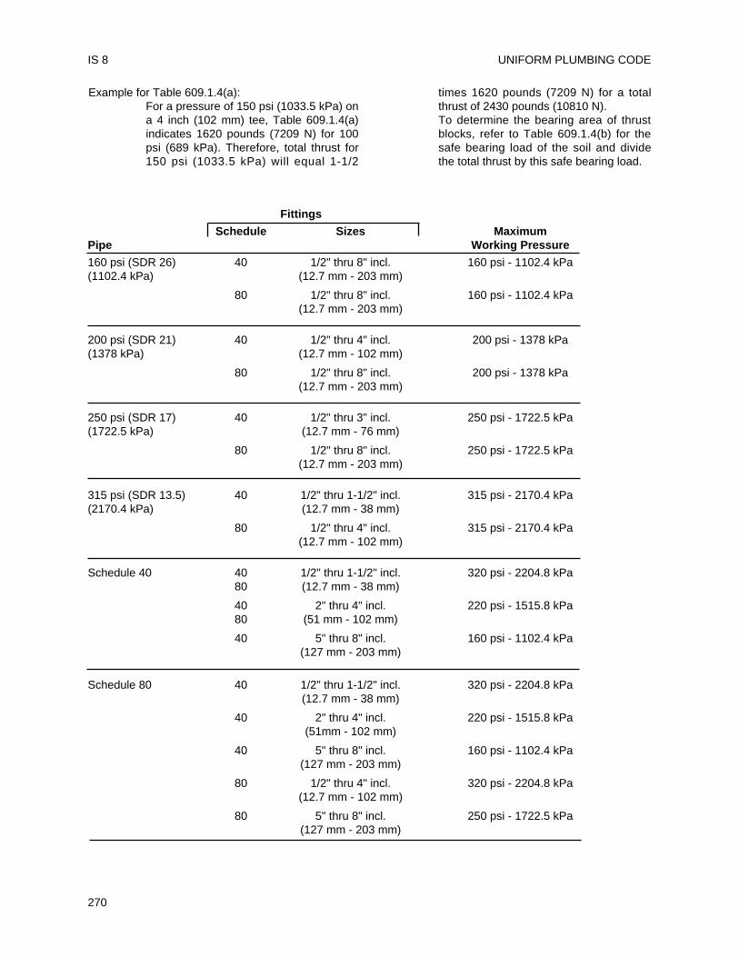
Example for Table 609.1.4(a):For a pressure of 150 psi (1033.5 kPa) ona 4 inch (102 mm) tee, Table 609.1.4(a)indicates 1620 pounds (7209 N) for 100psi (689 kPa). Therefore, total thrust for150 psi (1033.5 kPa) will equal 1-1/2
times 1620 pounds (7209 N) for a totalthrust of 2430 pounds (10810 N).To determine the bearing area of thrustblocks, refer to Table 609.1.4(b) for thesafe bearing load of the soil and dividethe total thrust by this safe bearing load.
UNIFORM PLUMBING CODE
270
IS 8
Fittings
Schedule Sizes MaximumPipe Working Pressure
160 psi (SDR 26) 40 1/2" thru 8" incl. 160 psi - 1102.4 kPa(1102.4 kPa) (12.7 mm - 203 mm)
80 1/2" thru 8" incl. 160 psi - 1102.4 kPa(12.7 mm - 203 mm)
200 psi (SDR 21) 40 1/2" thru 4" incl. 200 psi - 1378 kPa(1378 kPa) (12.7 mm - 102 mm)
80 1/2" thru 8" incl. 200 psi - 1378 kPa(12.7 mm - 203 mm)
250 psi (SDR 17) 40 1/2" thru 3" incl. 250 psi - 1722.5 kPa(1722.5 kPa) (12.7 mm - 76 mm)
80 1/2" thru 8" incl. 250 psi - 1722.5 kPa(12.7 mm - 203 mm)
315 psi (SDR 13.5) 40 1/2" thru 1-1/2" incl. 315 psi - 2170.4 kPa(2170.4 kPa) (12.7 mm - 38 mm)
80 1/2" thru 4" incl. 315 psi - 2170.4 kPa(12.7 mm - 102 mm)
Schedule 40 40 1/2" thru 1-1/2" incl. 320 psi - 2204.8 kPa80 (12.7 mm - 38 mm)
40 2" thru 4" incl. 220 psi - 1515.8 kPa80 (51 mm - 102 mm)
40 5" thru 8" incl. 160 psi - 1102.4 kPa(127 mm - 203 mm)
Schedule 80 40 1/2" thru 1-1/2" incl. 320 psi - 2204.8 kPa(12.7 mm - 38 mm)
40 2" thru 4" incl. 220 psi - 1515.8 kPa(51mm - 102 mm)
40 5" thru 8" incl. 160 psi - 1102.4 kPa(127 mm - 203 mm)
80 1/2" thru 4" incl. 320 psi - 2204.8 kPa(12.7 mm - 102 mm)
80 5" thru 8" incl. 250 psi - 1722.5 kPa(127 mm - 203 mm)
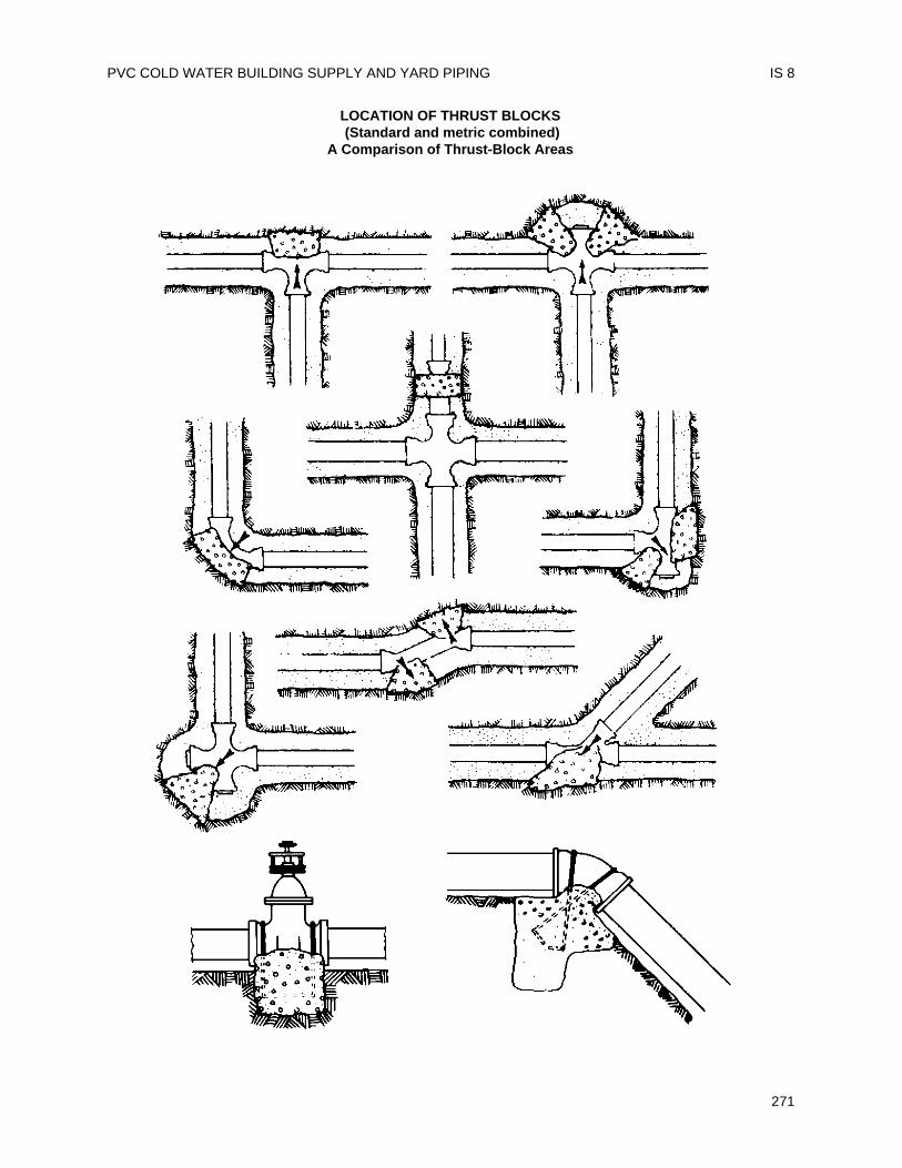
PVC COLD WATER BUILDING SUPPLY AND YARD PIPING IS 8
271
LOCATION OF THRUST BLOCKS(Standard and metric combined)
A Comparison of Thrust-Block Areas
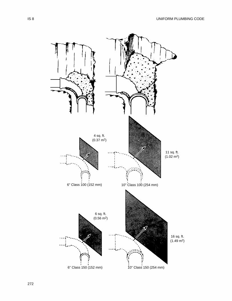
UNIFORM PLUMBING CODE
272
IS 8
4 sq. ft.(0.37 m2)
11 sq. ft.(1.02 m2)
6" Class 100 (152 mm) 10" Class 100 (254 mm)
6" Class 150 (152 mm) 10" Class 150 (254 mm)
16 sq. ft.(1.49 m2)
6 sq. ft.(0.56 m2)
TABLE 609.1.4(b)SAFE BEARING LOADS OF VARIOUS SOILS
Safe Bearing LoadSoil Lbs./sq. ft. kPaMulch, Peat, etc. 0 0Soft Clay 1000 6890Sand 2000 13,780Sand and Gravel 3000 20,670Sand anf Gravel Cement
with Clay 4000 27,360Hard Shale 10,000 68,900
Example: Assume a 4000 pound (17,800 N) totalthrust was computed. The soil conditionis sand. The required bearing area ofthe thrust block is 4,000 lbs. (17,800 N)divided by 2000 lbs. (13,780 kPa) or 2square feet (0.19 m2).
609.2 Testing609.2.1 Rubber Gasketed Joints. Properly
sized thrust blocks, either permanent ortemporary, shall be installed at allrequired points before testing. SeeSection 609.1.4. When concrete thrustblocks are installed, wait at least 24hours before pressure testing.
609.2.2 Solvent Cement Joints. The entiresystem shall be purged before testing toeliminate all solvent cement vapors andair.CAUTION: Water test only.
609.3 Identification . A label shall befastened to the main electrical meterpanel stating, "This structure has anonmetallic water service".
610.0 Sizing610.1 Piping shall be sized in accordance with
UPC Section 610.0. When UPCAppendix A is applicable, use UPCChart A-5 (Fairly smooth). Flow velocityshall not exceed 8 fps (2.4 m/s).
This standard is a combination of sections from theprevious standards IS 8 and IS 14. IS 8 wasoriginally adopted in 1968 and revised in 1971, 1972,1973 and 1975. IS 14 was originally adopted in 1972and revised in 1975. Upon adoption of this rewrite, IS14 was deleted.
Rewrite ratified by membership: 1978Revised: 1980, 1981, 1984, 1986, 1989, 1991, 1992
1 Appendix XI, Safety Requirements and Precautions fromASTM D2564-81a Solvent Cements for Poly (Vinyl Chloride)(PVC) Plastic Pipe and Fittings is reprinted with permissionfrom the American Society for Testing and Materials, 1916Race Street, Philadelphia, PA 19103, copyright.
PVC COLD WATER BUILDING SUPPLY AND YARD PIPING IS 8
273

UNIFORM PLUMBING CODE
274
This installation standard shall apply to PVCbuilding drain, waste and vent systems as governedby the Uniform Plumbing Code. Material StandardASTM D2665-85a, “Standard Specification for Poly(Vinyl Chloride) (PVC) Plastic Drain, Waste and VentPipe and Fittings”, shall form part of this installationstandard.
Installation, material and inspection shall complywith the current edition of the Uniform PlumbingCode published by the International Association ofPlumbing and Mechanical Officials and shall alsocomply with this standard.
Note: The Building Official shall be consulted aboutpenetration of fire separations, height and area orother limitations.
Note: The following sections of the UniformPlumbing Code apply.
202.0 Definition PVCTable 14-1 Pipe and Fittings
ASTM D2665-94 D2122-90ASTM D3311-941
301.1 Minimum Standards704.4.1 and 704.4.3 Closet Flanges
707.1 Cleanout Fittings311.8 Screwed Fittings310.0 Workmanship311.0 Prohibited Fittings and
Practices101.4.1.1 Repair and Alterations
313.0 Protection of Piping, Materialsand Structures
314.0 Hangers and Supports(Vertical Piping)
314.0 Hangers and Supports(Horizontal Piping)
103.5 Inspection103.5.3 Testing
701.0 Materials (Drainage)903.1 and 903.3 Materials (Venting)
903.4 Straining or Bending Pipe1003.0 Traps Described316.1.1 Threaded Joints316.1.6 Type of Joints – Solvent
Cement Plastic Pipe Joints
316.2.3 Special Joints316.3.1 Flanged Fixture Connections
316.4 Prohibited Joints andConnections
317.0 Increasers and Reducers1101.3 Materials Uses
ABBREVIATIONSASTM American Society for Testing and MaterialsIAPMO International Association of Plumbing and
Mechanical OfficialsUPC Uniform Plumbing Code
301.1 Minimum Standards301.1.1 Pipe
PVC pipe is furnished in straight lengths.The pipe is usually dark gray, ivory or whitein color with identification markings asshown below. The pipe wall is the samethickness as that of Schedule 40 (IPS)standard steel pipe.Pipe shall be marked on two sides 180degrees apart or spirally in letters not lessthan 3/16 inch (4.8 mm) high in a contrastingcolor and shall contain at least the followingat not more than 2 feet (610 mm) intervals:(a) Manufacturer’s name or trademark;(b) Nominal pipe size;(c) Symbol PVC-DWV2;(d) Products l isted by IAPMO that are
covered by this standard should belabeled with the designated IAPMOcertification mark; and
(e) Any other markings required orpermitted by law.
301.1.2 FittingsFittings are usually furnished in dark gray,ivory or white with indelible markings asshown below. Refer to Tables in ASTMD2665-94 and D3311-94 for dimensions andtolerances for pipe, fittings, sockets andlaying lengths.Fittings shall be marked on the body or hubon both sides. The markings shall consist ofat least the following:(a) Manufacturer’s name or trademark;
275
Installation StandardFor
PVC BUILDING DRAIN, WASTE AND VENT PIPE AND FITTINGS
IAPMO IS 9-95e1
1 Although referenced in this standard, some of the fittings shown in the standard are not acceptable under the Uniform PlumbingCode.2 It is common practice to dual mark Schedule 40 DWV and potable water piping in which compliance with each applicablestandard is met.
(b) Symbol PVC-DWV;(c) Products l isted by IAPMO that are
covered by this standard shall belabeled with the designated IAPMOcertification mark; and
(d) Any other markings required orpermitted by law
301.1.3 Solvent CementSolvent cement shall be as specified inASTM Standard D2564-96a.Solvent cement labels shall contain at leastthe following:(a) Manufacturer’s or supplier’s name and
address, trade name, trademark or both;(b) Cement for PVC (pipe and fittings);(c) ASTM designation D2564;(d) Lot number;(e) Recommended procedure for use and
safety precautions;(f) Cement type according to viscosity and
pipe size;(g) End use application;
(h) Products listed by IAPMO that arecovered by this standard shall belabeled with the designated IAPMOcertification mark; and
(i) Any other markings required orpermitted by law.
301.1.3.1 Solvent cements shall not be purple incolor.
301.1.4 PrimersPrimer shall be as specified in ASTMF656-93.Primer containers shall be marked with atleast the following:(a) Manufacturers or suppliers name and
address, trademark or trade name;(b) ASTM F656;(c) Function of primer;(d) Procedure or instructions for
application and use;(e) Lot number;(f) Primer intended for use with potable
water shall show compliance to NSF;and
(g) Products listed by IAPMO that arecovered by this standard shall belabeled with the designated IAPMOcertification mark.
301.1.4.1 Primer shall be purple.
310.0 Workmanship310.1 Alignment
All piping systems components shall bealigned properly without strain. Pipe shallnot be bent or pulled into posit ion.
Vertical piping shall be maintained instraight alignment between floors withmidstory guides.Pipe and fittings shall be so positionedthat identifying markings shall be readilyvisible for inspection.
313.0 Protection of Piping313.1 Storage
Pipe and fittings should not be stored indirect sunlight; however, exposure tosunlight during normal constructionperiods is not considered harmful. Pipeshall be stored in such a manner as toprevent sagging or bending.
313.2 Expansion and ContractionThermal expansion and contraction ofplastic drain waste and vent systems shallbe taken into consideration. Thermalexpansion and contraction may becontrolled by several methods: offset,expansion joints or restraints.Regardless of method utilized, certainconditions shall be met.(a) Support, but do not rigidly restrain
piping at changes of direction.(b) Do not anchor pipe rigidly in walls.(c) Holes through framing members must
be adequately sized to allow for freemovement.
DWV installation with frequent changes indirection will compensate for thermalexpansion and contraction.
Expansion joints may be utilized in verticalstraight runs in excess of 30 feet (9144 mm)provided they are installed permanufacturer’s installation instructions.Except piping buried below ground,horizontal and vertical piping should beinstalled with restraint fittings or a minimumof 24 inches (610 mm) 45° offset every 30feet (9144 mm). Thermal expansion forinstallation subject to temperature changesmay be determined from Table 3-1. Thelinear expansion shown is independent ofthe diameter of the pipe.
313.3 Exposed PipingPiping shall not be exposed to directsunlight. Exception: Vent piping throughroof. Plumbing vents through roof, exposedto sunlight, shall be protected by water basesynthetic latex paints.Adequate support shall be provided wherePVC piping is exposed to wind, snow andice loading.
UNIFORM PLUMBING CODE
276
IS 9
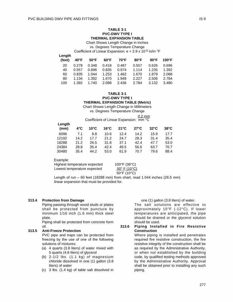
313.4 Protection from DamagePiping passing through wood studs or platesshall be protected from puncture byminimum 1/16 inch (1.6 mm) thick steelplate.Piping shall be protected from concrete formoil.
313.5 Anti-Freeze ProtectionPVC pipe and traps can be protected fromfreezing by the use of one of the followingsolutions of mixtures:(a) 4 quarts (3.8 liters) of water mixed with
5 quarts (4.8 liters) of glycerol(b) 2-1/2 lbs. (1.1 kg) of magnesium
chloride dissolved in one (1) gallon (3.8liters) of water
(c) 3 lbs. (1.4 kg) of table salt dissolved in
one (1) gallon (3.8 liters) of water.The salt solutions are effective toapproximately 10°F (-12°C). If lowertemperatures are anticipated, the pipeshould be drained or the glycerol solutionshould be used.
313.6 Piping Installed in Fire ResistiveConstructionWhere piping is installed and penetratesrequired fire resistive construction, the fireresistive integrity of the construction shall beas required by the Administrative Authority,or when not established by the buildingcode, by qualified testing methods approvedby the Administrative Authority. Approvalshall be obtained prior to installing any suchpiping.
PVC BUILDING DWV PIPE AND FITTINGS IS 9
277
TABLE 3-1PVC-DWV TYPE I
THERMAL EXPANSION TABLEChart Shows Length Change in Inches
vs. Degrees Temperature ChangeCoefficient of Linear Expansion: e = 2.9 x 10⁻⁵ in/in °F
Length(feet) 40°F 50°F 60°F 70°F 80°F 90°F 100°F
20 0.278 0.348 0.418 0.487 0.557 0.626 0.69640 0.557 0.696 0.835 0.974 1.114 1.235 1.39260 0.835 1.044 1.253 1.462 1.670 1.879 2.08880 1.134 1.392 1.670 1.949 2.227 2.506 2.784
100 1.392 1.740 2.088 2.436 2.784 3.132 3.480
TABLE 3-1PVC-DWV TYPE I
THERMAL EXPANSION TABLE (Metric)Chart Shows Length Change in Millimeters
vs. Degrees Temperature Change0.2 mm
Coefficient of Linear Expansion: mm °CLength(mm) 4°C 10°C 16°C 21°C 27°C 32°C 38°C
6096 7.1 8.8 10.6 12.4 14.2 15.9 17.712192 14.2 17.7 21.2 24.7 28.3 31.4 35.418288 21.2 26.5 31.8 37.1 42.4 47.7 53.024384 28.8 35.4 42.4 49.5 56.6 63.7 70.730480 35.4 44.2 53.0 61.9 70.7 79.6 88.4
Example:Highest temperature expected 100°F (38°C)Lowest temperature expected 50° F (10°C)
50°F (10°C)Length of run – 60 feet (18288 mm) from chart, read 1.044 inches (26.5 mm)linear expansion that must be provided for.
UNIFORM PLUMBING CODE
278
314.0 Hangers and Supports314.1 Abrasion
Hangers and straps shall not compress,distort, cut or abrade the piping and shallallow free movement of pipe. Pipe, exposedto damage by sharp surfaces, shall beprotected.
314.2 SupportSupport all horizontal piping at intervals ofnot more than four (4) feet (1219 mm), atend of branches, and at change of directionor elevation. Supports shall allow freemovement, but shall restrict upwardmovement of lateral runs so as not to createreverse grade. Vertical piping shall besupported at each story or floor level.Alignment of vertical piping shall bemaintained between floors with the use of amid-story guide. Support trap arms inexcess of three (3) feet (915 mm) in lengthas close as possible to the trap. Closetflanges shall be securely fastened withcorrosive resistant fasteners to the floor withtop surface one-quarter (1/4) inch (6.4 mm)above finish floor.
1003.0 Traps1003.1 Connection to Metal Traps
Traps shall be connected by means of listedthreaded trap adapters.
705.1 Joints705.1.1 Caulked Joints
Make connections or transitions to bell-and-spigot cast iron soil pipe fittings, and to bell-and-spigot pipe and fitt ings of othermaterials with l isted mechanicalcompression joints designed for this use, orcaulked joints made in an approved manner.In caulking, pack the joint with oakum orhemp and fill with molten lead to a depth ofnot less than one (1) inch (25.4 mm). Allowa period of four (4) minutes for cooling,following which, caulk the lead at the insideand outside edges of the joint. Lead shallnot be overheated.
316.1 Solvent Cement Joints(Additional information is available in ASTMD2855.)
316.1.1 Selection. Follow manufacturer’s recom-mendations for type of solvent cement forsuch conditions as temperature over 100°F(38°C), or humidity over 60%.
316.1.2 Handling (to maintain effectiveness).Solvent cement and primer containers no
larger than 1 quart (1 liter) should be used inthe field (to avoid thickening due toevaporation). Keep containers closed and inthe shade when not in use. Keep applicatorsubmerged in solvent cement betweenapplications. When solvent cement becomesthicker, THROW IT AWAY. Solvent cementshall NOT be thinned.
316.1.3 Size of Applicator. Applicator should beabout one-half the pipe diameter. Do not usesmall applicator on large pipes. Ordinarypure bristle paint brushes or applicatorsfurnished with product are satisfactory.
316.1.5 Primers. A listed primer in compliance withASTM F 656-93 shall be used on all PVCDWV joints.
316.1.6 Application. Solvent cement and primershall be applied deliberately, but withoutdelay (two men may be needed to makelarge joints). Use special care whentemperature is over 100°F (38°C) orhumidity is over 60%.
316.1.7 Procedure.XI. SAFETY REQUIREMENTS AND
PRECAUTIONSXI.1 General. Solvents contained in
PVC plastic pipe cements areclassified as airborne contaminantsand flammable and combustibleliquids. Precautions listed in thisappendix should be followed toavoid injury to personnel and thehazard of fire.
XI.2 Safety Precautions:XI.2.1 Prolonged breathing of solvent
vapors should be avoided. Whenpipe and fittings are being joined inpartial ly enclosed areas, aventilating device should be used insuch a manner to minimize theentry of vapors into the breathingareas.
XI.2.2 Solvent cements should be keptaway from all sources of ignition,heat, sparks and open flame.
XI.2.3 Containers for solvent cementsshould be kept tightly closed exceptwhen the cement is being used.
XI.2.4 All rags and other materials usedfor mopping up spills should be keptin a safety waste receptacle whichshould be emptied daily.
XI.2.5 Most of the solvents used in PVCpipe cements can be consideredeye irritants and contact with theeye should be avoided for it may
IS 9
cause eye injury. Proper eyeprotection and the use of chemicalgoggles or face shields is advisablewhere the possibility of splashingexists in handling solvent cements.In case of eye contact, flush withplenty of water for 15 minutes andcall a physician immediately.
XI.2.6 Repeated contact with the skinshould be avoided. Proper glovesimpervious to and unaffected by thesolvents should be worn whenfrequent contact with the skin islikely. Application of the solvents orsolvent cements with rags and barehand is not recommended. Brushesand other suitable applicators canbe used effectively for applying thesolvent cement, thus avoiding skincontact. In the event of excessivecontact, remove contaminatedclothing and wash skin with soapand water.
Step 1 Cut pipe square with hand saw andmiter box, mechanical cut-off sawor tube cutter designed for plastic.
Step 2 Ream inside and chamfer outsideof pipe (to eliminate all burrs).
Step 3 Clean all dirt, moisture and greasefrom pipe and socket. Use a clean,dry rag.
Step 4 Check dry fit of pipe in fitting. Pipeshould enter fitting socket from 1/3to 3/4 depth of socket.
Step 5 Soften inside socket surface byapplying an aggressive primer.
Step 6 Soften mating outside surface ofpipe to depth of socket by applyinga liberal coat of the (aggressive)primer. Be sure the entire surface issoftened.
Step 7 Again coat inside socket surfacewith the (aggressive) primer. Then,without delay, apply solvent cementliberally to outside of pipe. Usemore than enough to fill any gaps.
Step 8 Apply a light coat of PVC solventcement to inside of socket usingstraight outward strokes (to keepexcess solvent out of socket). Thisis also to prevent solvent cementdamage to pipe. For loosefits,apply a second coat of solventcement. Time is important at thisstage. See Section 316.1.5.
Step 9 While both the inside socketsurface and the outside surface ofthe pipe are SOFT and WET withsolvent cement, forcefully bottomthe pipe in the socket, giving thepipe a one-quarter turn, if possible.The pipe must go to the bottom ofthe socket.
Step 10 Hold the joint together until tight.(Partial set).
Step 11 Wipe excess cement from the pipe.A properly made joint will normallyshow a bead around its entireperimeter. Any gaps may indicateinsufficient cement or the use ofl ight bodied cement on largerdiameters where heavy bodiedcement should have been used.
Step 12 The system shall not be tested untilthe joints have cured (set) at leastas long as recommended by themanufacturer.
316.1.8 Threaded JointsListed adapter fittings shall be used for thetransition to threaded connections. Nothreaded PVC female fitting(s) or joint(s)shall be located in a non-accessible location.The joint between the PVC pipe and adapterfittings shall be of the solvent cement type.Only listed thread tape or thread lubricant,specifically intended for use with plastics,shall be used. Conventional pipe threadcompounds, putty, linseed oil base productsand unknown mixtures shall not be used.Pipe and fittings which have come in contactwith the above non-approved mixtures shallbe removed and replaced with new materials.Where a threaded joint is made, obtaintightness by maximum hand tightening plusadditional tightening with a strapwrench notto exceed one full turn.
316.2 Special Joints316.2.1 Connection to Non-Plastic Pipe
When connecting plastic pipe to other typesof piping, use listed fittings and adaptersdesigned for the specific use intended.
316.4 Prohibited Fittings and Connections(a) Drainage System – Any fitt ing or
connection which has an enlargement,chamber or recess with a ledge,shoulder or reduction of pipe area, thatoffers an obstruction to flow through thedrain is prohibited.
(b) No fitting or connection that offersabnormal obstruction to flow shall be
PVC BUILDING DWV PIPE AND FITTINGS IS 9
279
used. The enlargement of a three (3)inch (76 mm) closet bend or stub to four(4) inches (102 mm) shall not beconsidered an obstruction.
ADOPTED: 1968REVISED: 1971, 1974, 1975, 1976, 1977, 1981,
1982, 1983, 1987, 1989, 1990, 1991,1992
UNIFORM PLUMBING CODE
280
IS 9
This Installation Standard shall apply to ABSBuilding Sewer Pipe and Fittings as governed by theUniform Plumbing Code. Material Standard ASTMD2751-96a, Standard Specification for ABS SewerPipe and Fittings shall form part of this InstallationStandard. Materials shall be limited to building sewersreceiving domestic sewage excluding special andindustrial waste.
Note: The following sections of the UniformPlumbing Code apply.
202.0 Definition ABS202.0 Domestic Sewage
Table 14-1 ASTM D27511
301.1 Minimum Standards310.0 Workmanship312.0 Independent Systems
101.4.1.1.2 Repairs and Alterations313.3 and 313.4 Protection of Piping, Materials,
and Structures314.0 Hangers and Supports315.0 Trenching, Excavation, and
Backfill103.5 Inspection and Testing723.0 Building Sewer Test
705.1.1 Caulked Joints316.1.6 Types of Joint705.1.7 Elastomeric Gasketed and
Rubber-Ring Joints317.0 Increasers/Reducers713.0 Sewer Required715.0 Building Sewer Materials718.0 Grade, Support, and Protection
of Building Sewers719.0 Cleanouts720.0 Sewer and Water Pipes
1 Although this standard is referenced in Table 14-1, some ofthe tube or fittings shown in the standard are not acceptable foruse under the Uniform Plumbing Code.
301.1 Minimum Standards301.1.1 Pipe
ABS pipe is furnished in straight lengths.Refer to Tables in D2751-96a fordimensions and tolerances for pipe and pipesockets.Pipe shall be marked on two sides 180° apartor spirally in letters not less than 1/4 inch (6.4mm) high in a contrasting color and shall
contain at least the following at no more that 5foot (1524 mm) intervals:(a) Manufacturer's name or trademark and
code;(b) Nominal pipe size;(c) The legend “ABS Sewer Pipe.”(d) ASTM Designation D 2751;(e) Pipe SDR number;(f) Products listed by IAPMO that are
covered by this standard shall belabeled with the designated IAPMOcertification mark;
(g) Any other marking required or permittedby law; and
(h) Coextruded pipe shall be marked coex.301.1.2 Fittings
Refer to Tables in ASTM D2751-96a fordimensions and tolerances for f i t t ingsockets, spigots and laying lengths. Fittingsshall be marked on the body or hub. Themarkings shall consist of at least thefollowing:(a) Manufacturer’s name or trademark;(b) Nominal size;(c) The material designation “ABS.”(d) ASTM Designation D 2751;(e) Products listed by IAPMO that are
covered by this standard shall belabeled with the designated IAPMOcertification mark; and
(f) Any other markings required orpermitted by law.
301.1.3 Solvent CementSolvent cement shall be as specified inASTM Standard D2235-96a.Solvent cement labels shall contain at leastthe following:(a) Manufacturer's name or trademark;(b) Cement for ABS (Pipe and Fittings);(c) ASTM designation D 2235;(d) Recommended procedure for use and
safety precautions;(e) Products listed by IAPMO that are
covered by this Standard shall belabeled with the designated IAPMOcertification mark; and
(f) Any other marking required orpermitted by law.
281
Installation StandardFor
ABS SEWER PIPE AND FITTINGS
IAPMO IS 11-87e1
310.0 Workmanship310.1 Alignment
All piping system components shall bealigned properly without strain. Pipe shallnot be bent or pulled into position afterbeing solvent cemented. Pipe and fittingsshall be so positioned that identifyingmarkings shall be readily visible forinspection.
313.0 Protection of Piping313.1 Storage
Pipe and fittings should not be stored forlong periods in direct sunlight. However,exposure to direct sunlight during normalconstruction periods is not harmful. Pipeshall be stored in such a manner as toprevent sagging or bending.
315.0 Trenching, Excavation, and Backfill315.1 Trenching
The width of the trench at any point belowthe top of the pipe should not be greaterthan necessary to provide adequate roomfor joining the pipe and compacting the sidefills.
315.2 Alignment and GradeThe pipe should be bedded true to line andgrade, uniformly and continuously supportedon firm, stable material. Blocking shall notbe used to bring the pipe to grade. Thebedding shall conform to Section 718.0 ofthe Uniform Plumbing Code.
315.3 BackfillThe backfill shall conform to Section 315.0of the Uniform Plumbing Code.
705.0 Joints705.1 Caulked Joints
Make connections or transitions to bell-and-spigot cast iron soil pipe and fittings, and tobell-and-spigot pipe and fittings of othermaterials with approved mechanicalcompression joints designed for this use, orcaulked joints made in an approved manner.In caulking, pack the joint with oakum orhemp and fill with molten lead to a depth ofnot less than one (1) inch (25.4 mm). Allowa period of four (4) minutes for cooling,following which, caulk the lead at the insideand outside edges of the joint. Lead shallnot be overheated.Note: Caulked joints should be avoided ifpossible.
705.2 Gasket-Type JointsPipe shall be cut square with saws or pipecutters designed specifically for plastic pipe;
protect pipe and fitt ings from serratedholding devices and abrasion.1. Wipe the pipe spigot, rubber gasket,
and inside of the socket clean of all dirtand moisture.
2. Coat the socket and gasket evenly witha vegetable base paste lubricant.
3. Slide the gasket on the spigot andagainst the backup ring and snap it toremove any twist.
4. Force the spigot into the socket. Checkthat the joint is properly connected byusing any thin feeler gauge that thegasket is not looped back over thebackup ring.
316.0 Solvent Cement Joints316.1 Selection. Solvent cement shall be
recommended for ABS by the manufacturer.Follow manufacturer’s recommendations fortypes of solvent cement for such conditionsas temperature over 100°F (38°C), orhumidity over 60%.
316.1.1 Handling (to maintain effectiveness).Solvent cement containers no larger than 1quart (1 liter) should be used in the field (toavoid thickening due to evaporation). Keepcontainer closed and in the shade when notin use. Keep applicator submerged insolvent cement between applications.When solvent cement becomes thicker,THROW IT AWAY. Solvent cement shallNOT be thinned.
316.1.2 Size of Applicator. Applicator should beabout one half the pipe diameter. Do notuse small applicator on large pipes.Ordinary pure bristle paint brush orapplicators furnished with product aresatisfactory.
316.1.3 Application. Solvent cement shall beapplied deliberately, but without delay (twomen may be needed to make large joints).Use special care when temperature is over100°F (38°C) or humidity is over 60%.
316.1.5 ProcedureX1 SAFETY REQUIREMENTS AND
PRECAUTIONSX1.1 General. Solvents contained in
ABS plastic pipe cements areclassified as airborne contaminantsand flammable and combustibleliquids. Precautions listed in thisappendix should be followed toavoid injury to personnel and thehazard of fire.
UNIFORM PLUMBING CODE
282
IS 11
X1.2 Safety Precautions:X1.2.1 Prolonged breathing of solvent
vapors should be avoided. Whenpipe and fittings are being joined inpartial ly enclosed areas, aventilating device should be used insuch a manner to minimize theentry of vapors into the breathingareas.
X1.2.2 Solvent cements should be keptaway from all sources of ignition,heat, sparks, and open flame.
X1.2.3 Containers for solvent cementsshould be kept tightly closed exceptwhen the cement is being used.
X1.2.4 All rags and other materials used formopping up spills should be kept ina safety waste receptacle whichshould be emptied daily.
X1.2.5 Most of the solvents used in ABSpipe cements can be consideredeye irritants and contact with theeye should be avoided for it maycause eye injury. Proper eyeprotection and the use of chemicalgoggles or face shields is advisablewhere the possibility of splashingexists in handling solvent cements.In case of eye contact, flush withplenty of water for 15 minutes andcall a physician immediately.
X1.2.6 Repeated contact with the skinshould be avoided. Proper glovesimpervious to and unaffected by thesolvents should be worn whenfrequent contact with the skin islikely. Application of the solvents orsolvent cements with rags and barehand is not recommended. Brushesand other suitable applicators canbe used effectively for applying thesolvent cement, thus avoiding skincontact. In the event of excessivecontact, remove contaminatedclothing and wash skin with soapand water.
Step 1 Cut pipe square with hand saw andmiter box, mechanical cut-off saw ortube cutter designed for plastic.
Step 2 Ream inside and chamfer outside ofpipe (to eliminate all burrs).
Step 3 Clean all dirt, moisture, and greasefrom pipe and socket. Use a clean,dry rag.
Step 4 Check dry fit of pipe in fitting. Pipeshould enter fitting socket from 1/3
to 3/4 depth of socket.Step 5 Apply a light coat of ABS solvent
cement to inside of socket usingstraight outward strokes (to keepexcess solvent out of socket). Thisis also to prevent solvent cementdamage to pipe. For loose fits,apply a second coat of solventcement. Time is important at thisstage. See Section 316.1.3.
Step 6 While both the inside socket surfaceand the outside surface of the pipeare SOFT and WET with solventcement, forcefully bottom the pipe inthe socket, giving the pipe a one-quarter turn, if possible. The pipemust go to the bottom of the socket.
Step 7 Hold the joint together until tight(partial set).
Step 8 Wipe excess cement from the pipe.A properly made joint will normallyshow a bead around its entireperimeter. Any gaps may indicateinsufficient cement or the use ofl ight bodied cement on largerdiameters where heavy bodiedcement should have been used.
Step 9 The system shall not be tested untilthe joints have cured (set) at leastas long as recommended by themanufacturer.
316.2 Special Joints316.2.1 Connection to Non-Plastic Pipe
When connecting plastic pipe to other typespiping, use only approved types of fittingsand adapters, designed for the specifictransition intended.
ADOPTED: 1976REVISED: 1981, 1987
ABS SEWER PIPE AND FITTINGS IS 11
283

UNIFORM PLUMBING CODE
284
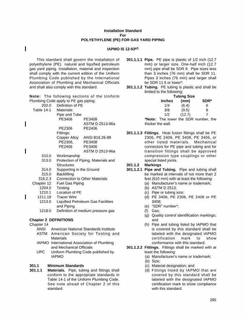
This standard shall govern the installation ofpolyethylene (PE) natural and liquified petroleumgas yard piping. Installation, material and inspectionshall comply with the current edition of the UniformPlumbing Code published by the InternationalAssociation of Plumbing and Mechanical Officialsand shall also comply with this standard.
Note: The following sections of the UniformPlumbing Code apply to PE gas piping:
202.0 Definition of PETable 14-1 Materials:
Pipe and TubePE3406 PE3408
ASTM D 2513-96aPE2306 PE2406
Fittings:Copper Alloy ANSI B16.26-88PE2306, PE3408PE2406 PE3406
ASTM D 2513-96a310.0 Workmanship313.0 Protection of Piping, Materials and
Structures314.0 Supporting in the Ground315.0 Backfilling
316.2.3 Connection to Other MaterialsChapter 12 Fuel Gas Piping
1204.0 Testing1210.1 Location of PE
1211.18 Tracer Wire1213.0 Liquified Petroleum Gas Facilities
and Piping1218.0 Definition of medium pressure gas
Chapter 2 DEFINITIONSChapter 14
ANSI American National Standards InstituteASTM American Society for Testing and
MaterialsIAPMO International Association of Plumbing
and Mechanical OfficialsUPC Uniform Plumbing Code published by
IAPMO
301.1 Minimum Standards301.1.1 Materials. Pipe, tubing and fittings shall
conform to the appropriate standards inTable 14-1 of the Uniform Plumbing Code.See note ahead of Chapter 2 of thisstandard.
301.1.1.1 Pipe. PE pipe is plastic of 1/2 inch (12.7mm) or larger size. One-half inch (12.7mm) pipe shall be SDR 9. Pipe sizes lessthan 3 inches (76 mm) shall be SDR 11.Pipes 3 inches (76 mm) and larger shallbe SDR 11.5 or lower*.
301.1.1.2 Tubing. PE tubing is plastic and shall belimited to the following:
Tubing SizeInches (mm) SDR*
1/4 (6.4) 63/8 (9.5) 81/2 (12.7) 7
*Note: The lower the SDR number, thethicker the wall.
301.1.1.3 Fittings. Heat fusion fittings shall be PE2306, PE 2406, PE 3408, PE 3406, orother l isted materials. Mechanicalconnectors for PE pipe and tubing and fortransit ion f i t t ings shall be approvedcompression type couplings or otherspecial listed joints.
301.1.2 Markings301.1.2.1 Pipe and Tubing. Pipe and tubing shall
be marked at intervals of not more than 2feet (610 mm) with at least the following:(a) Manufacturer’s name or trademark;(b) ASTM D 2513;(c) Pipe or tubing size;(d) PE 3406, PE 2306, PE 2406 or PE
3408;(e) “SDR” number*;(f) Gas;(g) Quality control identification markings;
and(h) Pipe and tubing listed by IAPMO that
is covered by this standard shall belabeled with the designated IAPMOcertif ication mark to showconformance with this standard.
301.1.2.2 Fittings. Fittings shall be marked with atleast the following:(a) Manufacturer’s name or trademark;(b) Size;(c) Material designation; and(d) Fittings listed by IAPMO that are
covered by this standard shall belabeled with the designated IAPMOcertification mark to show compliancewith this standard.
285
Installation StandardFor
POLYETHYLENE (PE) FOR GAS YARD PIPING
IAPMO IS 12-93e1
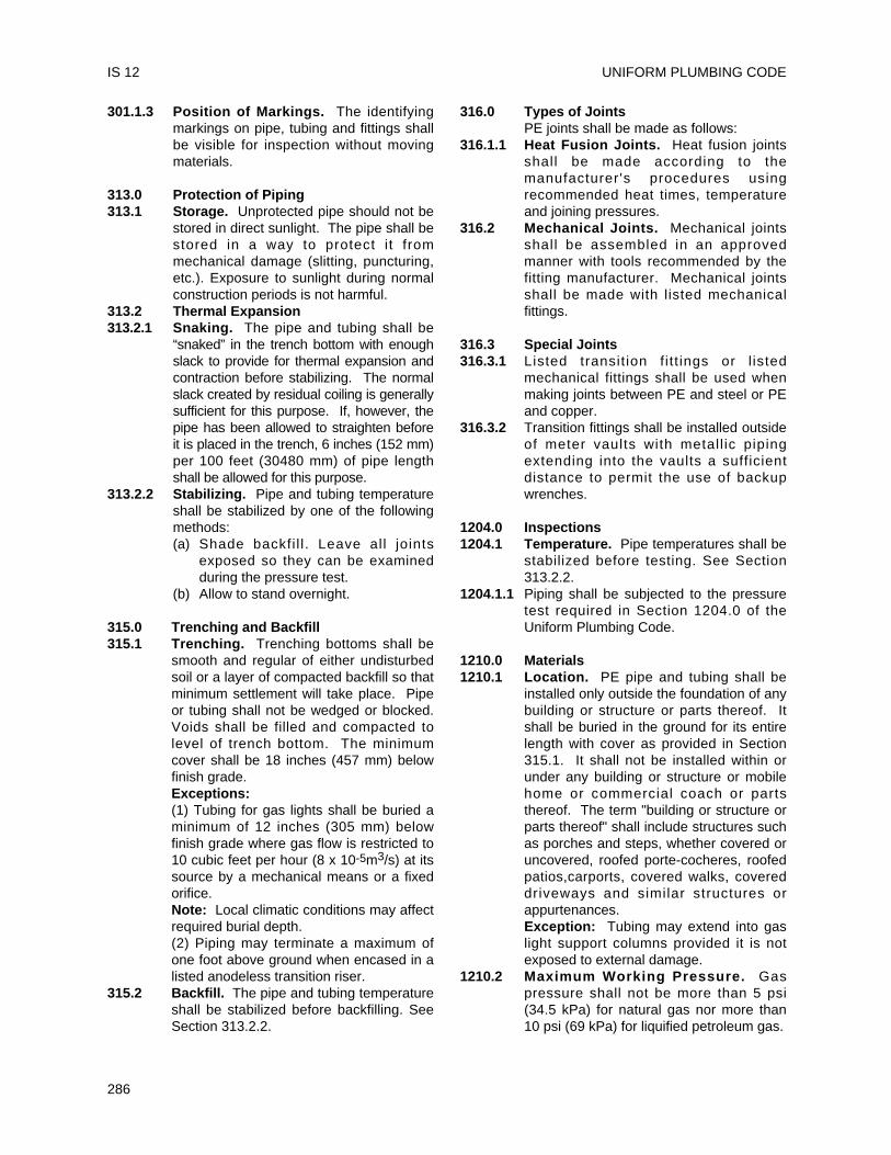
301.1.3 Position of Markings. The identifyingmarkings on pipe, tubing and fittings shallbe visible for inspection without movingmaterials.
313.0 Protection of Piping313.1 Storage. Unprotected pipe should not be
stored in direct sunlight. The pipe shall bestored in a way to protect i t frommechanical damage (slitting, puncturing,etc.). Exposure to sunlight during normalconstruction periods is not harmful.
313.2 Thermal Expansion313.2.1 Snaking. The pipe and tubing shall be
“snaked” in the trench bottom with enoughslack to provide for thermal expansion andcontraction before stabilizing. The normalslack created by residual coiling is generallysufficient for this purpose. If, however, thepipe has been allowed to straighten beforeit is placed in the trench, 6 inches (152 mm)per 100 feet (30480 mm) of pipe lengthshall be allowed for this purpose.
313.2.2 Stabilizing. Pipe and tubing temperatureshall be stabilized by one of the followingmethods:(a) Shade backfi l l . Leave all joints
exposed so they can be examinedduring the pressure test.
(b) Allow to stand overnight.
315.0 Trenching and Backfill315.1 Trenching. Trenching bottoms shall be
smooth and regular of either undisturbedsoil or a layer of compacted backfill so thatminimum settlement will take place. Pipeor tubing shall not be wedged or blocked.Voids shall be filled and compacted tolevel of trench bottom. The minimumcover shall be 18 inches (457 mm) belowfinish grade.Exceptions: (1) Tubing for gas lights shall be buried aminimum of 12 inches (305 mm) belowfinish grade where gas flow is restricted to10 cubic feet per hour (8 x 10⁻⁵m3/s) at itssource by a mechanical means or a fixedorifice.Note: Local climatic conditions may affectrequired burial depth.(2) Piping may terminate a maximum ofone foot above ground when encased in alisted anodeless transition riser.
315.2 Backfill. The pipe and tubing temperatureshall be stabilized before backfilling. SeeSection 313.2.2.
316.0 Types of JointsPE joints shall be made as follows:
316.1.1 Heat Fusion Joints. Heat fusion jointsshall be made according to themanufacturer's procedures usingrecommended heat times, temperatureand joining pressures.
316.2 Mechanical Joints. Mechanical jointsshall be assembled in an approvedmanner with tools recommended by thefitting manufacturer. Mechanical jointsshall be made with listed mechanicalfittings.
316.3 Special Joints316.3.1 Listed transit ion f i t t ings or l isted
mechanical fittings shall be used whenmaking joints between PE and steel or PEand copper.
316.3.2 Transition fittings shall be installed outsideof meter vaults with metall ic pipingextending into the vaults a sufficientdistance to permit the use of backupwrenches.
1204.0 Inspections1204.1 Temperature. Pipe temperatures shall be
stabilized before testing. See Section313.2.2.
1204.1.1 Piping shall be subjected to the pressuretest required in Section 1204.0 of theUniform Plumbing Code.
1210.0 Materials1210.1 Location. PE pipe and tubing shall be
installed only outside the foundation of anybuilding or structure or parts thereof. Itshall be buried in the ground for its entirelength with cover as provided in Section315.1. It shall not be installed within orunder any building or structure or mobilehome or commercial coach or partsthereof. The term "building or structure orparts thereof" shall include structures suchas porches and steps, whether covered oruncovered, roofed porte-cocheres, roofedpatios,carports, covered walks, covereddriveways and similar structures orappurtenances.Exception: Tubing may extend into gaslight support columns provided it is notexposed to external damage.
1210.2 Maximum Working Pressure. Gaspressure shall not be more than 5 psi(34.5 kPa) for natural gas nor more than10 psi (69 kPa) for liquified petroleum gas.
UNIFORM PLUMBING CODE
286
IS 12
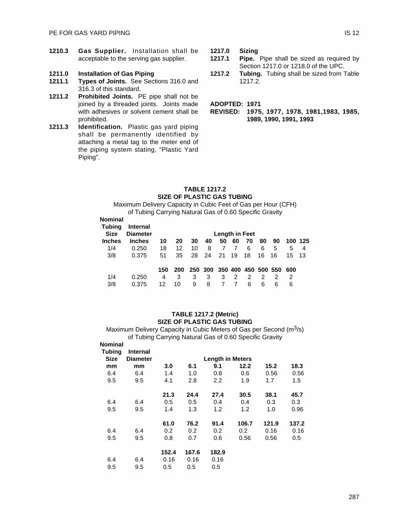
1210.3 Gas Supplier. Installation shall beacceptable to the serving gas supplier.
1211.0 Installation of Gas Piping1211.1 Types of Joints. See Sections 316.0 and
316.3 of this standard.1211.2 Prohibited Joints. PE pipe shall not be
joined by a threaded joints. Joints madewith adhesives or solvent cement shall beprohibited.
1211.3 Identification. Plastic gas yard pipingshall be permanently identif ied byattaching a metal tag to the meter end ofthe piping system stating, "Plastic YardPiping".
1217.0 Sizing1217.1 Pipe. Pipe shall be sized as required by
Section 1217.0 or 1218.0 of the UPC.1217.2 Tubing. Tubing shall be sized from Table
1217.2.
ADOPTED: 1971REVISED: 1975, 1977, 1978, 1981,1983, 1985,
1989, 1990, 1991, 1993
PE FOR GAS YARD PIPING IS 12
287
TABLE 1217.2SIZE OF PLASTIC GAS TUBING
Maximum Delivery Capacity in Cubic Feet of Gas per Hour (CFH) of Tubing Carrying Natural Gas of 0.60 Specific Gravity
NominalTubing Internal
Size Diameter Length in FeetInches Inches 10 20 30 40 50 60 70 80 90 100 125
1/4 0.250 18 12 10 8 7 7 6 6 5 5 43/8 0.375 51 35 28 24 21 19 18 16 16 15 13
150 200 250 300 350 400 450 500 550 6001/4 0.250 4 3 3 3 3 2 2 2 2 23/8 0.375 12 10 9 8 7 7 6 6 6 6
TABLE 1217.2 (Metric)SIZE OF PLASTIC GAS TUBING
Maximum Delivery Capacity in Cubic Meters of Gas per Second (m3/s)of Tubing Carrying Natural Gas of 0.60 Specific Gravity
NominalTubing Internal
Size Diameter Length in Metersmm mm 3.0 6.1 9.1 12.2 15.2 18.36.4 6.4 1.4 1.0 0.8 0.6 0.56 0.569.5 9.5 4.1 2.8 2.2 1.9 1.7 1.5
21.3 24.4 27.4 30.5 38.1 45.76.4 6.4 0.5 0.5 0.4 0.4 0.3 0.39.5 9.5 1.4 1.3 1.2 1.2 1.0 0.96
61.0 76.2 91.4 106.7 121.9 137.26.4 6.4 0.2 0.2 0.2 0.2 0.16 0.169.5 9.5 0.8 0.7 0.6 0.56 0.56 0.5
152.4 167.6 182.96.4 6.4 0.16 0.16 0.169.5 9.5 0.5 0.5 0.5

UNIFORM PLUMBING CODE
288
Installation and material of protective pipecoatings shall comply with this Standard and thecurrent edition of the Uniform Plumbing Code,published by the International Association ofPlumbing and Mechanical Officials (IAPMO).
Note: The following sections of the Uniform PlumbingCode shall apply to protectively coated pipe.
301.1 Marking and labeling302.0 Wrought iron and steel pipe sizing310.0 Workmanship311.0 Prohibited fittings and practices313.5 Protection required314.0 Burial of piping604.0 Materials – water piping
609.3.1 Coated protection required1210.0 Materials – gas piping1211.5 Coated protection required1211.6 Coating material approval required
301.1 Minimum Standards301.1.1 Materials301.1.1.1 Coating. Piping shall be coated by an
IAPMO listed coating applicator inaccordance with the following standards:AWWA C203-97 “Coal-Tar ProtectiveCoatings and Linings for Steel WaterPipelines - Enameled and Tape - HotApplied”AWWA 215-94 “Extruded PolyolefinCoatings for the Exterior of Steel WaterPipelines”AWWA 213-96 “Fusion-Bonded EpoxyCoating for the Interior and Exterior of SteelWater Pipelines”
301.1.1.2 Tape. Tape for field application shallcomply with PS-37-90, Black Plastic PVC orPE Pressure-Sensitive CorrosionPreventive Tape.
301.1.1.3 Primer. Primer for field application shallbe compatible with the tape and be asrecommended by the tape manufacturer.
301.1.2 Markings301.1.2.1 Pipe. Protectively coated pipe shall be
legibly marked at least every two (2) feet(610 mm) as follows:(a) Applicator’s name or trademark;(b) Pipe manufacturer's name;(c) Pipe Standard designation i.e., ASTM
or API;
(d) Pipe material type i.e., Black,Galvanized;
(e) Pipe size and schedule;(f) Coating material;(g) Holiday test voltage;(h) Products listed by IAPMO that are
covered by this Standard shall belabeled with the designated IAPMOcertification mark; and
(i) Any other required markings.301.1.2.2 Tape. Tape for field applications should
be legibly marked at least every two (2)feet (610 mm) with the manufacturer'sname and tape model identification.
313.0 Protection of Piping and Fittings313.1 Field Joints. Field joints shall be made
as follows, except as specified in 313.2.Clean and dry surfaces to be protected.Step 1 Oil and grease, if present, shall
be removed with suitable non-oilytype solvent such as Heptane orTrichlorethylene. Materials, suchas kerosene and gasoline, shallnot be used.
Step 2 For coated pipe, remove coatingapproximately 3 inches (76 mm)from end of pipe or from repairarea and bevel to exposeshoulder of coating at area to befield wrapped.
Step 3 For taped pipe, remove tape andoverwrapping so as to exposeapproximately 3 inches (76 mm)of pipe at area to be fieldwrapped.
Step 4 For welded pipe, grind downsharp welds and weld spatter to aminimum 1/8 inch (3.2 mm)radius. Wire brush the weld areathoroughly taking care to removeas much mil scale and surfacerust as possible. Remove anyloose or charred coating causedduring welding.
Step 5 Apply listed primer, asrecommended by the manufacturerof the tape being applied, over theprotected area and adjacent 1 inch(25.4 mm) of protected area.
289
Installation StandardFor
PROTECTIVELY COATED PIPE
IAPMO IS 13-91e1
Step 6 Spirally wrap listed tape by a halfoverlap double wrap of minimum10 mil tape stretched around thefitt ing, thread and otherunprotected areas to provide aminimum 40 mil thickness. Amaximum of two (2) inch (51 mm)wide tape shall be used for fieldapplication.Exception: Unless otherwiselisted by IAPMO, a maximum ofone (1) inch (25.4 mm) wide tapeshall be used on change ofdirection fittings for piping sizesup to and including two (2) inch(51 mm).
313.2 Other Methods. Other materialsapproved for field joints or repair shall beapplied as per manufacturer'srecommendations and the IAPMO listingrequirements.
313.3 Damage in Shipment. Coated pipingshall be protected against damage inshipment.
313.4 Handling and Storage. Coated pipingshall be handled and stored in a mannerto prevent damage.
313.5 Handling by Installer. Movement of pipefrom truck or into trench shall be done insuch a manner as to avoid abrasion, ordamage from dropping.
315.0 Backfill. All excavations shall becompletely backfi l led as soon afterinspection as possible.
1211.9 Inspection. All coated piping shall beinspected and tested and any visible void,damage or imperfection to the pipecoating shall be repaired as to comply withSection 313.0.
1211.9.1 Equipment. The equipment, material,and labor necessary for inspection or testsshall be furnished by the person to whomthe permit is issued or by whom inspectionis requested.
ADOPTED: 1971REVISED: 1975, 1978, 1982, 1984, 1991
UNIFORM PLUMBING CODE
290
IS 13
This standard shall govern the installation ofasbestos cement pressure pipe and fittings withelastomeric gasketed joints in hot and cold waterbuilding supply and yard piping. For allowablelocation and pressure, see Sections 604.1 and609.1.2 of this standard. Installation, material, andinspection shall comply with the current edition of theUniform Plumbing Code published by theInternational Association of Plumbing and MechanicalOfficials, and shall also comply with this standard.
Note: The following sections of the UniformPlumbing Code apply to asbestos cement pressurepiping systems.
Table 14-1 Materials310.0 Workmanship313.0 Protection of Piping, Materials
and Structures314.0 Supporting in the Ground315.0 Backfilling
Chapter 6 Water Distribution
Chapter 2 DEFINITIONS202.0 AC Asbestos CementChapter 14 ASTM American Society for Testing
and MaterialsIAPMO International Association of
Plumbing and MechanicalOfficials
UPC Uniform Plumbing Codepublished by IAPMO
301.1 Minimum Standards301.1.1 Material. Materials shall conform to the
appropriate standard in Table 14-1 of theUniform Plumbing Code.Applicable StandardsAC Pipe ASTM C296-93Fittings AWWA/ANSI A21.10-93Rings ASTM D1869-94Joints AWWA/ANSI A21.11-93
301.1.1.1 Pipe. Pipe is asbestos cement.301.1.1.2 Fittings. Fittings are cast iron or other
listed materials.301.1.2 Markings301.1.2.1 Pipe. Each uncut length of pipe shall be
marked with at least the following:(a) Manufacturers name or trademark;(b) Size and Class;(c) Date of manufacture;
(d) Test Pressure; and(e) Pipe listed by IAPMO that is covered
by this standard shall be labeled withthe designated IAPMO certificationmark to show compliance with thisStandard.
301.1.2.2 Fittings. Fittings should be marked withat least the following:(a) Initials of makers name;(b) Year of casting;(c) Nominal Diameter; and(d) Weight and Class.
301.1.2.3 Couplings. Couplings shall be markedwith at least the following:(a) Manufacturers name or trademark;(b) Class and nominal size; and(c) Letter "T".
301.1.3 Position of Markings. The identifyingmarkings on pipe and fittings shall bevisible for inspection without movingmaterials unless otherwise acceptable tothe Administrative Authority.
315.0 Trenching, Cover, and Backfill315.1 Trenching and Cover. Trench bottoms
shall be uniformly graded and shall be ofeither undisturbed soil or shall consist of alayer or layers of compacted backfill sothat minimum settlement will take place.The trench bottoms shall be at least 12inches (305 mm) below the average localfrost depth. The minimum cover shall be18 inches (458 mm) below the finishgrade.
315.2 Backfill. After finishing pressure testingof the line, backfill a minimum of twelve(12) inches (305 mm) deep over the top ofthe pipe and fittings. Backfill should beselect material placed around the pipe in amanner to provide a firm continuoussupport. Tamp well to secure propercompaction.Note: All joints shall be exposed duringtest.
705.0 Joints705.1 Joints in asbestos cement pipe shall be a
sleeve coupling of the same compositionas the pipe, or of other listed materials,and sealed with rubber rings or joined byother listed compression type coupling.
291
Installation StandardFor
ASBESTOS CEMENT PRESSURE PIPE FOR WATER SERVICE AND YARD PIPING
IAPMO IS 15-82
705.1.1 Joints between asbestos cement pipe andother approved pipes shall be made bymeans of l isted adapter couplings.Special heat resistant rings asrecommended by the manufacturer mustbe used for temperatures in excess of140°F (60°C).
705.2 Before assembling the joint, the couplinggrooves, pipe ends, and rubber gasketmust be cleaned. The rubber gaskets arethen positioned in the grooves.
705.2.1 Use the pipe manufacturer's joint lubricantrecommended for potable waterapplication. Apply lubricant to themachined end of the pipe only, never tothe rubber gasket or groove, unlessspecifically recommended otherwise bythe manufacturer.
705.2.2 The end of the pipe and the coupling orfitting bell shall be assembled using a barand wood block or a pipe puller."Stabbing" or "popping" the pipe into thecoupling (pipe is suspended and swunginto the bell) is not recommended.
705.3 When a field cut is made, cut the pipesquare, using hand pipe-cutters which usea cutting edge, or hand saws. To properlyenter the rubber gasketed joint, the end ofthe pipe must be machined beforeinsertion, using hand machining tools.
604.0 Materials604.1 Location. Asbestos cement piping shall
be installed only outside the foundation ofany building or structure or parts thereof.It shall be buried in the ground for itsentire length except vertical piping may beextended above grade per Section 313.0of the Uniform Plumbing Code. It shall notbe installed within or under any building orstructure or mobile home or commercialcoach or parts thereof. The term "buildingor structure or parts thereof" shall includestructures such as porches and steps,roofed porte-cocheres, roofed patios,carports, covered walks, covereddriveways, and similar structures orappurtenances.
609.0 Installation, Testing, and Identification609.1 Installation609.1.1 Alignment and Deflection. Pipe and
fittings shall be aligned properly withoutstrain. Pipe may be deflected inaccordance with the manufacturer'srecommendations provided that it shall notbe permanently staked or blocked to
maintain this deflection. If soft soilconditions exist, deflected joints may bepermanently blocked or staked to maintainthe deflection. The amount of deflectionshall be: 5° for sizes 4 inch (101.6 mm)through 12 inch (305 mm); 4° for 14 inch(356 mm) and 16 inch (407 mm); 3-1/2°for 18 inch (457 mm) through 24 inch (610mm) for pipe belled on the job site. Forfactory-belled couplings, one half (1/2) theabove deflections by size shall be allowed.
609.1.2 Working Pressure. Maximum workingpressure shall be as follows:
MATERIALS, SIZES AND MAXIMUM WORKINGPRESSURES
Pipe Sizes Maximum PressureClass 100 4 – 24 inch incl. 100 psi
(102 – 610 mm incl.) (689 kPa)Class 150 4 – 24 inch incl. 150 psi
(102 – 610 mm incl.) (1033 kPa)Class 200 4 – 24 inch incl. 200 psi
(102 – 610 mm incl.) (1378 kPa)
609.1.3 Laterals and Saddles. Installation oflaterals, saddles, or tapped couplings inAC piping shall be as required by theirlistings.
609.1.4 Thrust Blocking. Thrust blocks shall beinstalled at:
(a) Changes in direction, as at tees andbends;
(b) Changes in size, as at reducers;(c) Stops, as at dead ends; and(d) Valves, where thrusts may be
expected.The size and type of thrust block shall bebased on the pressure rating of the pipe(or line test pressure, if greater thanpiping rating), pipe size and kind of soil609.1.4(b). Refer to Table 609.1.4(a) forthrust at fittings for a pressure of onehundred (100) pounds per square inch(689 kPa).
609.1.5 To determine the bearing area of thrustblocks, refer to Table 609.1.4(b) for thesafe bearing load of the soil and divide thetotal thrust by this safe bearing load.
609.1.6 Thrust blocks shall be located as shownon Chart 609.1.4(c).
609.2 Testing609.2.1 The portion of the line being tested should
be complete with thrust blocks or properlysized temporary thrust blocking. The linemay be pressure tested immediately afterinstallation, provided however, that ifpoured concrete thrust blocks have been
UNIFORM PLUMBING CODE
292
IS 15
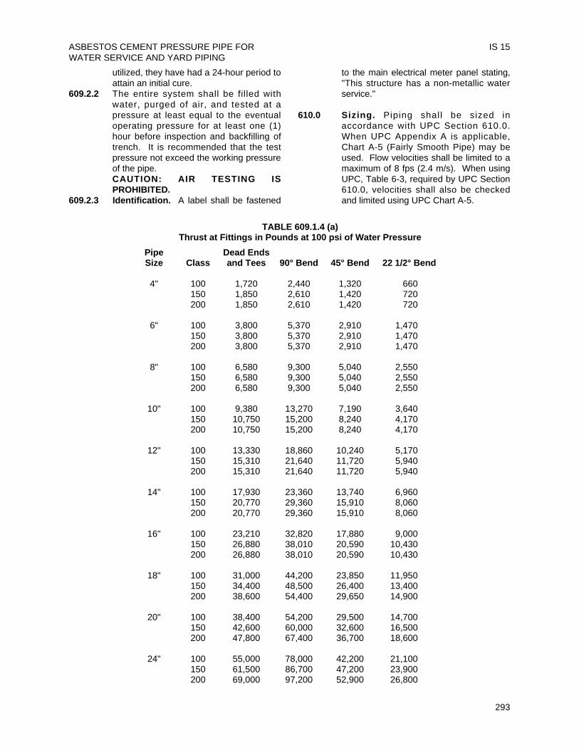
utilized, they have had a 24-hour period toattain an initial cure.
609.2.2 The entire system shall be filled withwater, purged of air, and tested at apressure at least equal to the eventualoperating pressure for at least one (1)hour before inspection and backfilling oftrench. It is recommended that the testpressure not exceed the working pressureof the pipe.CAUTION: AIR TESTING ISPROHIBITED.
609.2.3 Identification. A label shall be fastened
to the main electrical meter panel stating,"This structure has a non-metallic waterservice."
610.0 Sizing. Piping shall be sized inaccordance with UPC Section 610.0.When UPC Appendix A is applicable,Chart A-5 (Fairly Smooth Pipe) may beused. Flow velocities shall be limited to amaximum of 8 fps (2.4 m/s). When usingUPC, Table 6-3, required by UPC Section610.0, velocities shall also be checkedand limited using UPC Chart A-5.
ASBESTOS CEMENT PRESSURE PIPE FORWATER SERVICE AND YARD PIPING
IS 15
293
TABLE 609.1.4 (a)Thrust at Fittings in Pounds at 100 psi of Water Pressure
Pipe Dead EndsSize Class and Tees 90° Bend 45° Bend 22 1/2° Bend
4" 100 1,720 2,440 1,320 660150 1,850 2,610 1,420 720200 1,850 2,610 1,420 720
6" 100 3,800 5,370 2,910 1,470150 3,800 5,370 2,910 1,470200 3,800 5,370 2,910 1,470
8" 100 6,580 9,300 5,040 2,550150 6,580 9,300 5,040 2,550200 6,580 9,300 5,040 2,550
10" 100 9,380 13,270 7,190 3,640150 10,750 15,200 8,240 4,170200 10,750 15,200 8,240 4,170
12" 100 13,330 18,860 10,240 5,170150 15,310 21,640 11,720 5,940200 15,310 21,640 11,720 5,940
14" 100 17,930 23,360 13,740 6,960150 20,770 29,360 15,910 8,060200 20,770 29,360 15,910 8,060
16" 100 23,210 32,820 17,880 9,000150 26,880 38,010 20,590 10,430200 26,880 38,010 20,590 10,430
18" 100 31,000 44,200 23,850 11,950150 34,400 48,500 26,400 13,400200 38,600 54,400 29,650 14,900
20" 100 38,400 54,200 29,500 14,700150 42,600 60,000 32,600 16,500200 47,800 67,400 36,700 18,600
24" 100 55,000 78,000 42,200 21,100150 61,500 86,700 47,200 23,900200 69,000 97,200 52,900 26,800
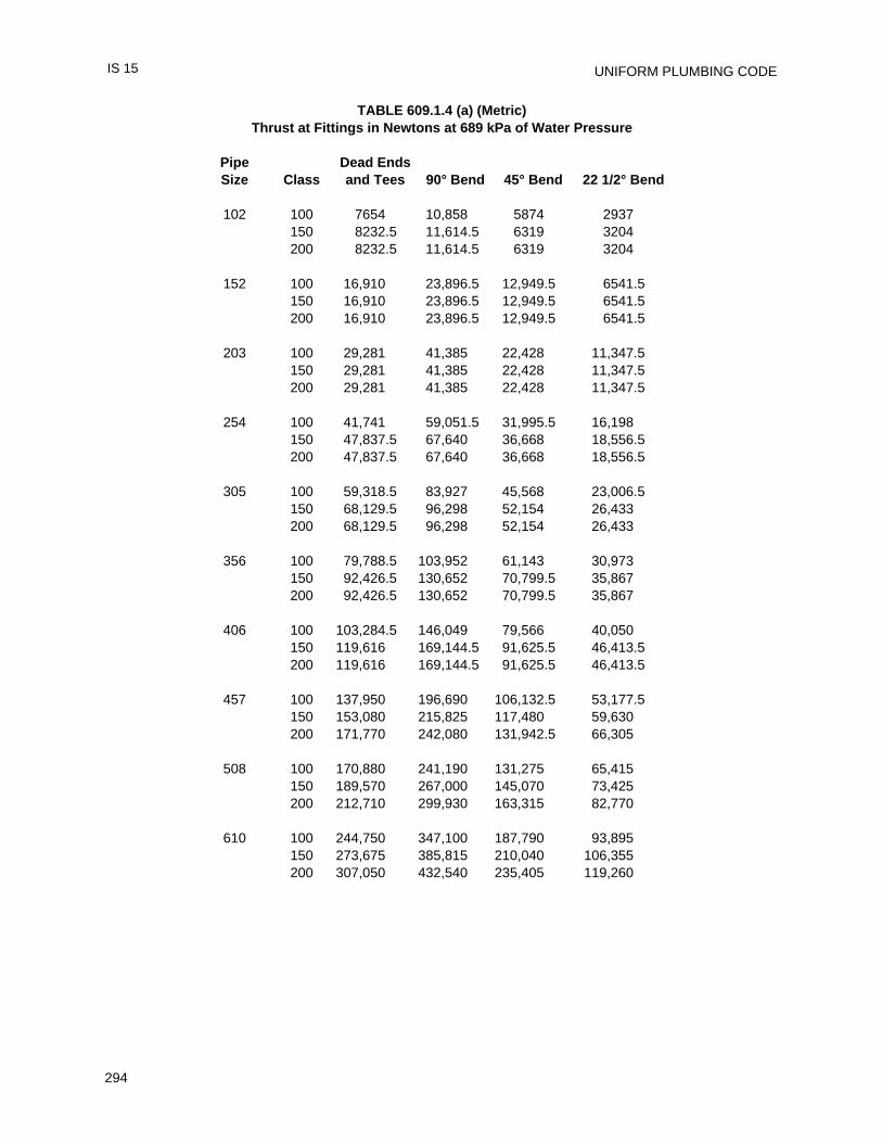
UNIFORM PLUMBING CODE
294
IS 15
TABLE 609.1.4 (a) (Metric)Thrust at Fittings in Newtons at 689 kPa of Water Pressure
Pipe Dead EndsSize Class and Tees 90° Bend 45° Bend 22 1/2° Bend
102 100 7654 10,858 5874 2937150 8232.5 11,614.5 6319 3204200 8232.5 11,614.5 6319 3204
152 100 16,910 23,896.5 12,949.5 6541.5150 16,910 23,896.5 12,949.5 6541.5200 16,910 23,896.5 12,949.5 6541.5
203 100 29,281 41,385 22,428 11,347.5150 29,281 41,385 22,428 11,347.5200 29,281 41,385 22,428 11,347.5
254 100 41,741 59,051.5 31,995.5 16,198150 47,837.5 67,640 36,668 18,556.5200 47,837.5 67,640 36,668 18,556.5
305 100 59,318.5 83,927 45,568 23,006.5150 68,129.5 96,298 52,154 26,433200 68,129.5 96,298 52,154 26,433
356 100 79,788.5 103,952 61,143 30,973150 92,426.5 130,652 70,799.5 35,867200 92,426.5 130,652 70,799.5 35,867
406 100 103,284.5 146,049 79,566 40,050150 119,616 169,144.5 91,625.5 46,413.5200 119,616 169,144.5 91,625.5 46,413.5
457 100 137,950 196,690 106,132.5 53,177.5150 153,080 215,825 117,480 59,630200 171,770 242,080 131,942.5 66,305
508 100 170,880 241,190 131,275 65,415150 189,570 267,000 145,070 73,425200 212,710 299,930 163,315 82,770
610 100 244,750 347,100 187,790 93,895150 273,675 385,815 210,040 106,355200 307,050 432,540 235,405 119,260
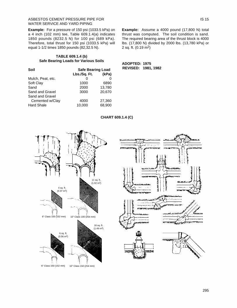
Example: For a pressure of 150 psi (1033.5 kPa) ona 4 inch (102 mm) tee, Table 609.1.4(a) indicates1850 pounds (8232.5 N) for 100 psi (689 kPa).Therefore, total thrust for 150 psi (1033.5 kPa) willequal 1-1/2 times 1850 pounds (82,32.5 N).
TABLE 609.1.4 (b)Safe Bearing Loads for Various Soils
Soil Safe Bearing LoadLbs./Sq. Ft. (kPa)
Mulch, Peat, etc. 0 0Soft Clay 1000 6890Sand 2000 13,780Sand and Gravel 3000 20,670Sand and Gravel
Cemented w/Clay 4000 27,360Hard Shale 10,000 68,900
Example: Assume a 4000 pound (17,800 N) totalthrust was computed. The soil condition is sand.The required bearing area of the thrust block is 4000lbs. (17,800 N) divided by 2000 lbs. (13,780 kPa) or2 sq. ft. (0.19 m2)
ADOPTED: 1975REVISED: 1981, 1982
ASBESTOS CEMENT PRESSURE PIPE FORWATER SERVICE AND YARD PIPING
IS 15
295
CHART 609.1.4 (C)
4 sq. ft.(0.37 m2)
11 sq. ft.(1.02 m2)
6" Class 100 (152 mm) 10" Class 100 (254 mm)
6" Class 150 (152 mm) 10" Class 150 (254 mm)
16 sq. ft.(1.49 m2)
6 sq. ft.(0.56 m2)

UNIFORM PLUMBING CODE
296
This Installation Test Standard is for use withsewer piping materials as listed in Table 14-1,Chapter 14, current edition of the Uniform PlumbingCode, as published by the International Associationof Plumbing and Mechanical Officials, hereinafterreferred to as IAPMO.
Note: The following section of the Uniform PlumbingCode applies to this test:
723.0 Testing1. Purpose:1.1 This Standard defines procedures for testing
sewer l ines, using low pressure air todemonstrate the integrity of the installedmaterial and the construction procedures.This recommended practice is for use intesting 3 inch (76 mm) through 12 inch (305mm) building sewer lines only.
2. General Requirement:2.1 The section of the building sewer line to be
tested is plugged. Air at low pressure isintroduced into the plugged line. Thecalculated test time for the pressure to dropis measured.
3. Procedure:Step 1 Plug all pipe outlets to resist
the test pressure. Give specialattention to stoppers andlaterals.
Step 2 Determine the test duration forthe section under test fromtable provided. The pressureholding time is based on anaverage holding pressure of 3psi (21 kPa) gage or a dropfrom 3.5 psi (24 kPa) to 2.5 psi(17 kPa) gage.
Step 3 Add air until the internal airpressure of the sewer line israised to approximately 4.0 psi(28 kPa) gage. After an internalpressure of approximately 4.0psig (28 kPa) is obtained, allowtime for the air pressure tostabilize. The pressure willnormally show some drop until
the temperature of the air in thetest section stabilizes.
Step 4 When the pressure hasstabilized and is at or above thestarting test pressure of 3.5 psi(24 kPa) gage, commence thetest. Before starting the test,the pressure may be allowed todrop to 3.5 psig (24 kPa).Record this drop in pressure forthe test period. If the pressurehas dropped more than 1.0 psi(7 kPa) gage during the testperiod, the line is presumed tohave failed. The test may bediscontinued when theprescribed test time has beencompleted even though the 1.0psig (7 kPa) drop has notoccurred.
4. Safety:4.1 The air test may be dangerous if,
because of lack of understanding orcarelessness, a l ine is improperlyprepared. It is extremely important thatthe various plugs be installed andbraced to prevent blowouts.
297
Installation StandardFor
LOW PRESSURE AIR TEST FOR BUILDING SEWERS
IAPMO IS 16-84
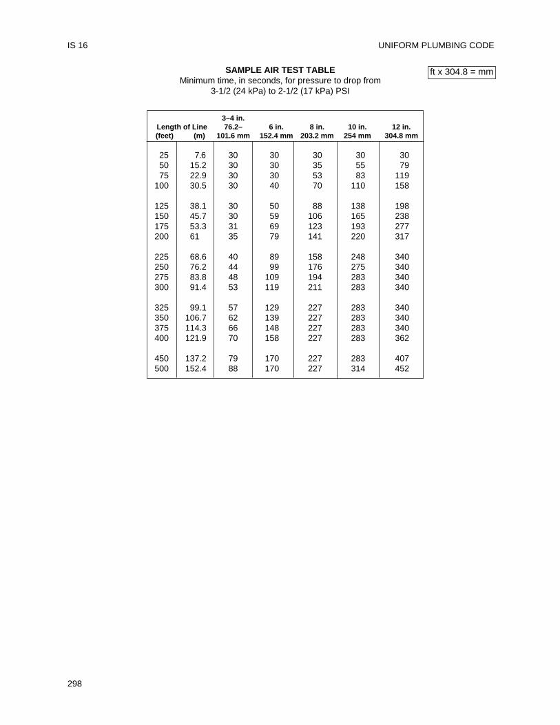
UNIFORM PLUMBING CODE
298
IS 16
SAMPLE AIR TEST TABLEMinimum time, in seconds, for pressure to drop from
3-1/2 (24 kPa) to 2-1/2 (17 kPa) PSI
3–4 in.Length of Line 76.2– 6 in. 8 in. 10 in. 12 in.(feet) (m) 101.6 mm 152.4 mm 203.2 mm 254 mm 304.8 mm
25 7.6 30 30 30 30 3050 15.2 30 30 35 55 7975 22.9 30 30 53 83 119
100 30.5 30 40 70 110 158
125 38.1 30 50 88 138 198150 45.7 30 59 106 165 238175 53.3 31 69 123 193 277200 61 35 79 141 220 317
225 68.6 40 89 158 248 340250 76.2 44 99 176 275 340275 83.8 48 109 194 283 340300 91.4 53 119 211 283 340
325 99.1 57 129 227 283 340350 106.7 62 139 227 283 340375 114.3 66 148 227 283 340400 121.9 70 158 227 283 362
450 137.2 79 170 227 283 407500 152.4 88 170 227 314 452
ft x 304.8 = mm
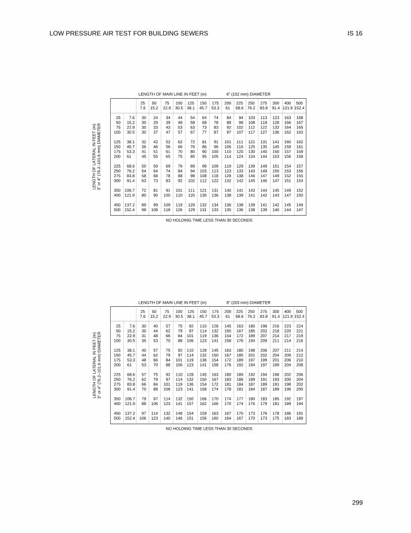
LOW PRESSURE AIR TEST FOR BUILDING SEWERS IS 16
299
LENGTH OF MAIN LINE IN FEET (m) 6" (152 mm) DIAMETER
NO HOLDING TIME LESS THAN 30 SECONDS
LENGTH OF MAIN LINE IN FEET (m) 8" (203 mm) DIAMETER
NO HOLDING TIME LESS THAN 30 SECONDS
25 50 75 100 125 150 175 200 225 250 275 300 400 5007.6 15.2 22.9 30.5 38.1 45.7 53.3 61 68.6 76.2 83.8 91.4 121.9 152.4
25 7.6 30 40 57 75 92 110 128 145 163 180 198 216 223 22450 15.2 30 44 62 79 97 114 132 150 167 185 202 218 220 22175 22.9 31 48 66 84 101 119 136 154 172 189 207 214 217 219
100 30.5 35 53 70 88 106 123 141 158 176 194 209 211 214 216
125 38.1 40 57 75 92 110 128 145 163 180 198 206 207 211 214150 45.7 44 62 79 97 114 132 150 167 185 201 202 204 209 212175 53.3 48 66 84 101 119 136 154 172 189 197 199 201 206 210200 61 53 70 88 106 123 141 158 176 192 194 197 199 204 208
225 68.6 57 75 92 110 128 145 163 180 189 192 194 196 202 206250 76.2 62 79 97 114 132 150 167 183 186 189 191 193 200 204275 83.8 66 84 101 119 136 154 172 181 184 187 189 191 198 202300 91.4 70 88 106 123 141 158 174 178 181 184 187 189 196 200
350 106.7 79 97 114 132 150 166 170 174 177 180 183 185 192 197400 121.9 88 106 123 141 157 162 166 170 174 176 179 181 189 194
450 137.2 97 114 132 148 154 159 163 167 170 173 176 178 186 191500 152.4 106 123 140 146 151 156 160 164 167 170 173 175 183 189
25 50 75 100 125 150 175 200 225 250 275 300 400 5007.6 15.2 22.9 30.5 38.1 45.7 53.3 61 68.6 76.2 83.8 91.4 121.9 152.4
25 7.6 30 24 34 44 54 64 74 84 94 103 113 123 163 16850 15.2 30 29 39 48 58 68 78 88 98 108 118 128 166 16775 22.9 30 33 43 53 63 73 83 92 102 112 122 132 164 165
100 30.5 30 37 47 57 67 77 87 97 107 117 127 136 162 163
125 38.1 32 42 52 62 72 81 91 101 111 121 131 141 160 162150 45.7 36 46 56 66 76 86 96 106 116 125 135 145 159 161175 53.3 41 51 61 70 80 90 100 110 120 130 140 150 157 159200 61 45 55 65 75 85 95 105 114 124 134 144 153 156 158
225 68.6 50 59 69 79 89 99 109 119 129 139 149 151 154 157250 76.2 54 64 74 84 94 103 113 123 133 143 149 150 153 156275 83.8 58 68 78 88 98 108 118 128 138 146 147 149 152 155300 91.4 63 73 83 92 102 112 122 132 142 145 146 147 151 154
350 106.7 72 81 91 101 111 121 131 140 141 143 144 145 149 152400 121.9 80 90 100 110 120 130 136 138 139 141 142 143 147 150
450 137.2 89 99 109 119 129 132 134 136 138 139 141 142 145 149500 152.4 98 108 118 126 129 131 133 135 136 138 139 140 144 147
LEN
GT
H O
F L
AT
ER
AL
IN F
EE
T (
m)
3" o
r 4"
(76
.2–1
01.6
mm
) D
IAM
ET
ER
LEN
GT
H O
F L
AT
ER
AL
IN F
EE
T (
m)
3" o
r 4"
(76
.2–1
01.6
mm
) D
IAM
ET
ER
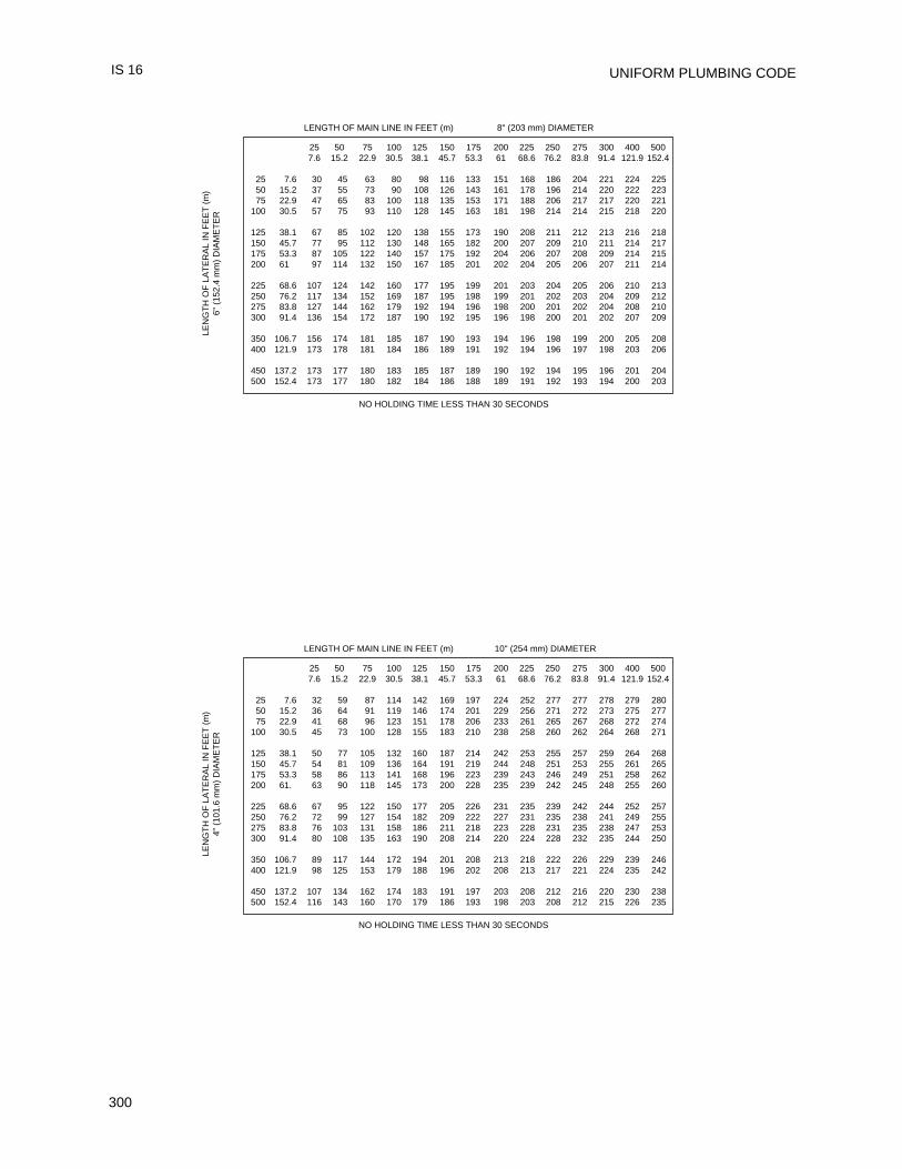
UNIFORM PLUMBING CODE
300
IS 16
LENGTH OF MAIN LINE IN FEET (m) 8" (203 mm) DIAMETER
NO HOLDING TIME LESS THAN 30 SECONDS
LENGTH OF MAIN LINE IN FEET (m) 10" (254 mm) DIAMETER
NO HOLDING TIME LESS THAN 30 SECONDS
25 50 75 100 125 150 175 200 225 250 275 300 400 5007.6 15.2 22.9 30.5 38.1 45.7 53.3 61 68.6 76.2 83.8 91.4 121.9 152.4
25 7.6 32 59 87 114 142 169 197 224 252 277 277 278 279 28050 15.2 36 64 91 119 146 174 201 229 256 271 272 273 275 27775 22.9 41 68 96 123 151 178 206 233 261 265 267 268 272 274
100 30.5 45 73 100 128 155 183 210 238 258 260 262 264 268 271
125 38.1 50 77 105 132 160 187 214 242 253 255 257 259 264 268150 45.7 54 81 109 136 164 191 219 244 248 251 253 255 261 265175 53.3 58 86 113 141 168 196 223 239 243 246 249 251 258 262200 61. 63 90 118 145 173 200 228 235 239 242 245 248 255 260
225 68.6 67 95 122 150 177 205 226 231 235 239 242 244 252 257250 76.2 72 99 127 154 182 209 222 227 231 235 238 241 249 255275 83.8 76 103 131 158 186 211 218 223 228 231 235 238 247 253300 91.4 80 108 135 163 190 208 214 220 224 228 232 235 244 250
350 106.7 89 117 144 172 194 201 208 213 218 222 226 229 239 246400 121.9 98 125 153 179 188 196 202 208 213 217 221 224 235 242
450 137.2 107 134 162 174 183 191 197 203 208 212 216 220 230 238500 152.4 116 143 160 170 179 186 193 198 203 208 212 215 226 235
25 50 75 100 125 150 175 200 225 250 275 300 400 5007.6 15.2 22.9 30.5 38.1 45.7 53.3 61 68.6 76.2 83.8 91.4 121.9 152.4
25 7.6 30 45 63 80 98 116 133 151 168 186 204 221 224 22550 15.2 37 55 73 90 108 126 143 161 178 196 214 220 222 22375 22.9 47 65 83 100 118 135 153 171 188 206 217 217 220 221
100 30.5 57 75 93 110 128 145 163 181 198 214 214 215 218 220
125 38.1 67 85 102 120 138 155 173 190 208 211 212 213 216 218150 45.7 77 95 112 130 148 165 182 200 207 209 210 211 214 217175 53.3 87 105 122 140 157 175 192 204 206 207 208 209 214 215200 61 97 114 132 150 167 185 201 202 204 205 206 207 211 214
225 68.6 107 124 142 160 177 195 199 201 203 204 205 206 210 213250 76.2 117 134 152 169 187 195 198 199 201 202 203 204 209 212275 83.8 127 144 162 179 192 194 196 198 200 201 202 204 208 210300 91.4 136 154 172 187 190 192 195 196 198 200 201 202 207 209
350 106.7 156 174 181 185 187 190 193 194 196 198 199 200 205 208400 121.9 173 178 181 184 186 189 191 192 194 196 197 198 203 206
450 137.2 173 177 180 183 185 187 189 190 192 194 195 196 201 204500 152.4 173 177 180 182 184 186 188 189 191 192 193 194 200 203
LEN
GT
H O
F L
AT
ER
AL
IN F
EE
T (
m)
6" (
152.
4 m
m)
DIA
ME
TE
RLE
NG
TH
OF
LA
TE
RA
L IN
FE
ET
(m
)4"
(10
1.6
mm
) D
IAM
ET
ER
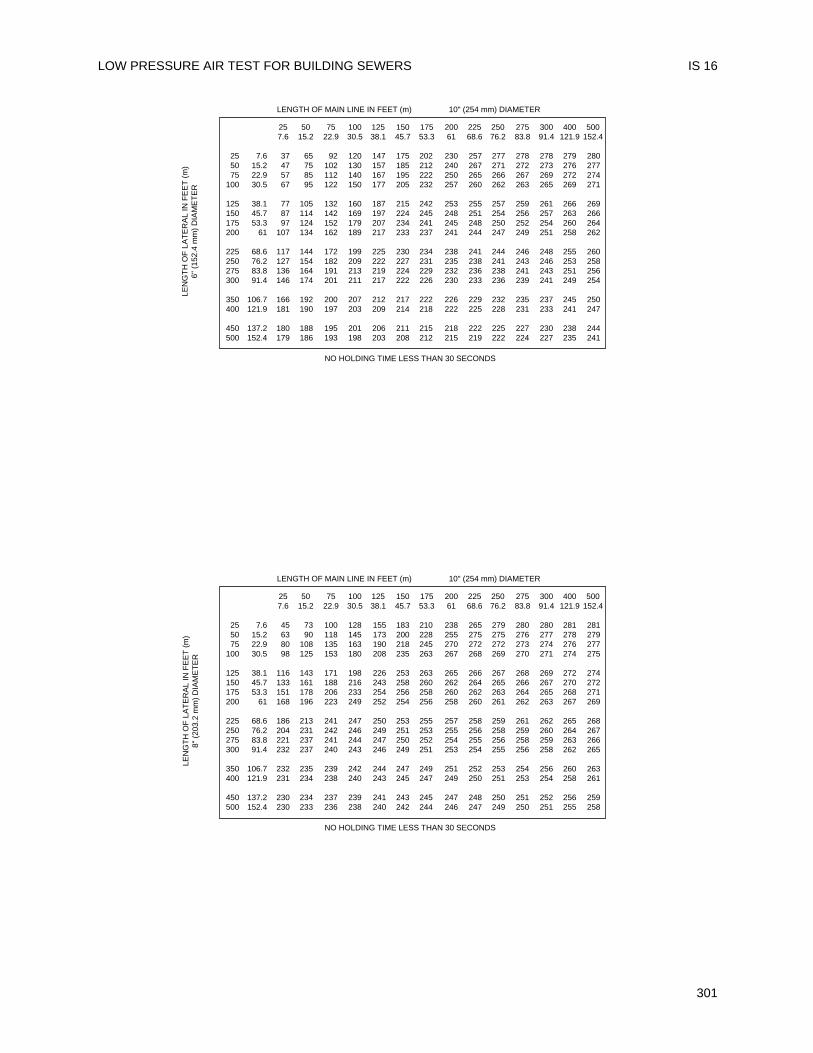
LOW PRESSURE AIR TEST FOR BUILDING SEWERS IS 16
301
LENGTH OF MAIN LINE IN FEET (m) 10" (254 mm) DIAMETER
NO HOLDING TIME LESS THAN 30 SECONDS
LENGTH OF MAIN LINE IN FEET (m) 10" (254 mm) DIAMETER
NO HOLDING TIME LESS THAN 30 SECONDS
25 50 75 100 125 150 175 200 225 250 275 300 400 5007.6 15.2 22.9 30.5 38.1 45.7 53.3 61 68.6 76.2 83.8 91.4 121.9 152.4
25 7.6 45 73 100 128 155 183 210 238 265 279 280 280 281 28150 15.2 63 90 118 145 173 200 228 255 275 275 276 277 278 27975 22.9 80 108 135 163 190 218 245 270 272 272 273 274 276 277
100 30.5 98 125 153 180 208 235 263 267 268 269 270 271 274 275
125 38.1 116 143 171 198 226 253 263 265 266 267 268 269 272 274150 45.7 133 161 188 216 243 258 260 262 264 265 266 267 270 272175 53.3 151 178 206 233 254 256 258 260 262 263 264 265 268 271200 61 168 196 223 249 252 254 256 258 260 261 262 263 267 269
225 68.6 186 213 241 247 250 253 255 257 258 259 261 262 265 268250 76.2 204 231 242 246 249 251 253 255 256 258 259 260 264 267275 83.8 221 237 241 244 247 250 252 254 255 256 258 259 263 266300 91.4 232 237 240 243 246 249 251 253 254 255 256 258 262 265
350 106.7 232 235 239 242 244 247 249 251 252 253 254 256 260 263400 121.9 231 234 238 240 243 245 247 249 250 251 253 254 258 261
450 137.2 230 234 237 239 241 243 245 247 248 250 251 252 256 259500 152.4 230 233 236 238 240 242 244 246 247 249 250 251 255 258
25 50 75 100 125 150 175 200 225 250 275 300 400 5007.6 15.2 22.9 30.5 38.1 45.7 53.3 61 68.6 76.2 83.8 91.4 121.9 152.4
25 7.6 37 65 92 120 147 175 202 230 257 277 278 278 279 28050 15.2 47 75 102 130 157 185 212 240 267 271 272 273 276 27775 22.9 57 85 112 140 167 195 222 250 265 266 267 269 272 274
100 30.5 67 95 122 150 177 205 232 257 260 262 263 265 269 271
125 38.1 77 105 132 160 187 215 242 253 255 257 259 261 266 269150 45.7 87 114 142 169 197 224 245 248 251 254 256 257 263 266175 53.3 97 124 152 179 207 234 241 245 248 250 252 254 260 264200 61 107 134 162 189 217 233 237 241 244 247 249 251 258 262
225 68.6 117 144 172 199 225 230 234 238 241 244 246 248 255 260250 76.2 127 154 182 209 222 227 231 235 238 241 243 246 253 258275 83.8 136 164 191 213 219 224 229 232 236 238 241 243 251 256300 91.4 146 174 201 211 217 222 226 230 233 236 239 241 249 254
350 106.7 166 192 200 207 212 217 222 226 229 232 235 237 245 250400 121.9 181 190 197 203 209 214 218 222 225 228 231 233 241 247
450 137.2 180 188 195 201 206 211 215 218 222 225 227 230 238 244500 152.4 179 186 193 198 203 208 212 215 219 222 224 227 235 241
LEN
GT
H O
F L
AT
ER
AL
IN F
EE
T (
m)
6" (
152.
4 m
m)
DIA
ME
TE
RLE
NG
TH
OF
LA
TE
RA
L IN
FE
ET
(m
)8"
(20
3.2
mm
) D
IAM
ET
ER
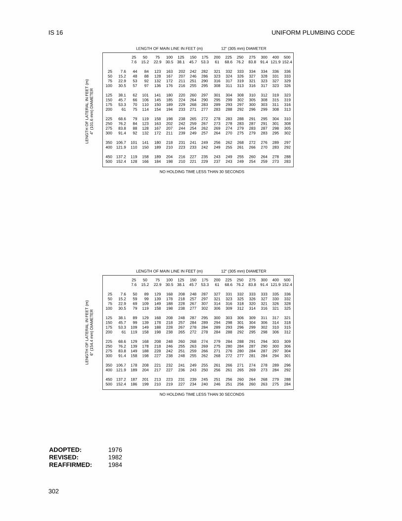
UNIFORM PLUMBING CODE
302
IS 16
LENGTH OF MAIN LINE IN FEET (m) 12" (305 mm) DIAMETER
NO HOLDING TIME LESS THAN 30 SECONDS
LENGTH OF MAIN LINE IN FEET (m) 12" (305 mm) DIAMETER
NO HOLDING TIME LESS THAN 30 SECONDS
ADOPTED: 1976REVISED: 1982REAFFIRMED: 1984
25 50 75 100 125 150 175 200 225 250 275 300 400 5007.6 15.2 22.9 30.5 38.1 45.7 53.3 61 68.6 76.2 83.8 91.4 121.9 152.4
25 7.6 50 89 129 168 208 248 287 327 331 332 333 333 335 33650 15.2 59 99 139 178 218 257 297 321 323 325 326 327 330 33275 22.9 69 109 149 188 228 267 307 314 316 318 320 321 326 328
100 30.5 79 119 158 198 238 277 302 306 309 312 314 316 321 325
125 38.1 89 129 168 208 248 287 295 300 303 306 309 311 317 321150 45.7 99 139 178 218 257 284 289 294 298 301 304 306 314 318175 53.3 109 149 188 228 267 278 284 289 293 296 299 302 310 315200 61 119 158 198 238 265 272 278 284 288 292 295 298 306 312
225 68.6 129 168 208 248 260 268 274 279 284 288 291 294 303 309250 76.2 139 178 218 246 255 263 269 275 280 284 287 290 300 306275 83.8 149 188 228 242 251 259 266 271 276 280 284 287 297 304300 91.4 158 198 227 238 248 255 262 268 272 277 281 284 294 301
350 106.7 178 208 221 232 241 249 255 261 266 271 274 278 289 296400 121.9 189 204 217 227 236 243 250 256 261 265 269 273 284 292
450 137.2 187 201 213 223 231 239 245 251 256 260 264 268 279 288500 152.4 186 199 210 219 227 234 240 246 251 256 260 263 275 284
25 50 75 100 125 150 175 200 225 250 275 300 400 5007.6 15.2 22.9 30.5 38.1 45.7 53.3 61 68.6 76.2 83.8 91.4 121.9 152.4
25 7.6 44 84 123 163 202 242 282 321 332 333 334 334 336 33650 15.2 48 88 128 167 207 246 286 323 324 326 327 328 331 33375 22.9 53 92 132 172 211 251 290 316 317 319 321 323 327 329
100 30.5 57 97 136 176 216 255 295 308 311 313 316 317 323 326
125 38.1 62 101 141 180 220 260 297 301 304 308 310 312 319 323150 45.7 66 106 145 185 224 264 290 295 299 302 305 308 315 319175 53.3 70 110 150 189 229 268 283 289 293 297 300 303 311 316200 61 75 114 154 194 233 271 277 283 288 292 296 299 308 313
225 68.6 79 119 158 198 238 265 272 278 283 288 291 295 304 310250 76.2 84 123 163 202 242 259 267 273 278 283 287 291 301 308275 83.8 88 128 167 207 244 254 262 269 274 279 283 287 298 305300 91.4 92 132 172 211 239 249 257 264 270 275 279 283 295 302
350 106.7 101 141 180 218 231 241 249 256 262 268 272 276 289 297400 121.9 110 150 189 210 223 233 242 249 255 261 266 270 283 292
450 137.2 119 158 189 204 216 227 235 243 249 255 260 264 278 288500 152.4 128 166 184 198 210 221 229 237 243 249 254 259 273 283
LEN
GT
H O
F L
AT
ER
AL
IN F
EE
T (
m)
4" (
101.
6 m
m)
DIA
ME
TE
RLE
NG
TH
OF
LA
TE
RA
L IN
FE
ET
(m
)6"
(15
4.4
mm
) D
IAM
ET
ER
This standard shall govern the installation ofextra strength vitrified clay pipe in gravity buildingdrains. (See Section 315.0 for allowable location.)Installation, material, and inspection shall complywith the current edition of the Uniform PlumbingCode published by the International Association ofPlumbing and Mechanical Officials and this standard.
Note: The following sections of the UniformPlumbing Code apply to vitrified clay pipe.
202.0 Definitions, Building DrainTable 14-1 Extra Strength
Vitrified Clay PipeASTM C700-97Fittings, Couplings,Molded Rubber ASTM C425-97
310.0 Workmanship313.0 Protection of Piping, Materials, and
Structures Direct embedment inconcrete or masonry
314.0 Supporting in the Ground315.0 Backfill103.5 Inspections
103.5.3.2 Test103.5.4.2 Responsibility
712.2 Water Test712.3 Air Test
103.5.3.5 ExceptionsChapter 7 Drainage
701.1.3 Location of piping and use inpressurized drainage systems
316.1.5 Joints705.3.1 Use of Joints
Chapter 2 DEFINITIONSChapter 14
ASTM American Society for Testing andMaterials
IAPMO International Association of Plumbingand Mechanical Officials
UPC Uniform Plumbing Code published byIAPMO
301.1 Minimum Standards301.1.1 Materials. Pipe and fittings shall be a
minimum 3 inch (76 mm) in size, "ExtraStrength" and couplings shall be moldedrubber sewer couplings. They shallconform to the applicable standards inTable 14-1 of the UPC.
301.1.2 Markings301.1.2.1 Pipe and Fittings. Each length of pipe
and each fitting shall be marked with atleast the following:(a) Manufacturer's name or initials;(b) "Extra Strength" or "ES";(c) Location of the plant; and(d) Pipe and fittings listed by IAPMO that
are covered by this Standard shall belabeled with the designated IAPMOcertification mark to show compliancewith this Standard.
301.1.2.2 Couplings. Couplings assemblies shallbe marked with at least the following:(a) Manufacturer's name or trademark on
rubber couplings and take-up band orscrew take-up housing;
(b) Size, on rubber coupling;(c) Year of manufacture on rubber
coupling;(d) Grade of material on take-up band or
screw take-up housing; and(e) Couplings and components listed by
IAPMO that are covered by thisStandard shall be labeled with thedesignated IAPMO certification mark toshow compliance with this Standard.
315.0 Burial and Separation315.1 Burial. Pipe and fittings shall be buried
12 inches (305 mm) minimum.315.2 Separation. Pipe and fittings shall not be
run or laid in the same trench with waterpiping unless both the fol lowingconditions are met:(1) The bottom of the water pipe, at all
points, shall be at least 12 inches(305 mm) above the top of the drainline, and
(2) The water pipe shall be placed on asolid shelf excavated at one side ofthe common trench.
316.0 Type of JointsJoints shall be made with couplings orwith f lexible compression factoryfabricated joints.
303
Installation StandardFor
EXTRA STRENGTH VITRIFIED CLAY PIPE IN BUILDING DRAINS
IAPMO IS 18-85e1
705.0 Use of JointsTransit ions between clay and othermaterials shall be made with moldedrubber sewer couplings and appropriatebushings or reducers.
ADOPTED: 1980REVISED: 1982, 1985
UNIFORM PLUMBING CODE
304
IS 18
This standard shall govern the installation ofCPVC piping (IPS pipe and SDR-11 tubing) inpotable hot and cold water distributing systemswithin buildings. (For allowable locations andpressure, see Sections 609.2 and 609.4.)Installation, material and inspection shall comply withthe current edition of the UPC, published by theInternational Association of Plumbing andMechanical Officials, and shall also comply with thisstandard.
Note: The following sections of the UniformPlumbing Code apply to CPVC IPS piping and SDR-11 tubing.
Table 14-1Chlorinated Poly (Vinyl Chloride) (CPVC)
Plastic Hot Water Distribution SystemASTM D 2846-97
Chlorinated Poly (Vinyl Chloride) (CPVC) Plastic Pipe, Schedules 40 and 80 ASTM F 441-97
Socket Type Chlorinated Poly (Vinyl Chloride) (CPVC) Plastic Pipe Fittings Schedule 40ASTM F 438-97
Socket Type Chlorinated Poly (Vinyl Chloride) (CPVC) Plastic Pipe Fittings Schedule 80ASTM F 439-97
Solvent Cements for Chlorinated Poly (Vinyl Chloride) (CPVC) Plastic Pipe and FittingsASTM F 493-97
301.1 Minimum Standards310.0 Workmanship311.0 Prohibited Fittings and Practices313.0 Protection of Piping, Materials
and Structures314.0 Hangers and Supports103.5 Inspections
316.2.3 Connection to other materialsChapter 6 Water Distribution
Chapter 2* DEFINITIONS202.0 CPVC Chlorinated Poly (Vinyl Chloride)
Pipe or tubing "Pipe" or "Piping" includes both pipe and piping, unless specified as "IPS Pipe" or "tubing".
Chapter 14ASTM American Society for Testing and
MaterialsIAPMO International Association of Plumbing
and Mechanical OfficialsNSF National Sanitation FoundationUPC Uniform Plumbing Code published by
IAPMO
*The first three numbers refer to the corresponding section ofthe UPC.
301.1 Minimum Standards301.1.1 Materials. Materials shall comply with
the following:
Materials ASTMStandard
Raw Material-CPVC 23447-B D 1784-97IPS PipeSch. 40 (1/2 in., 3/4 in. and 1 in.) F 441-97(12.7 mm, 19.1 mm, and 25.4 mm)Sch. 80 (1/2 in. – 2 in.) F 441-97(12.7 mm – 51 mm)TubingSDR 11 (1/2 in. thru 2 in.) D 2846-97(12.7 mm – 51mm)FittingsSch. 40 (1/2 in., 3/4 in. & 1 in.) F 438-97(12.7 mm, 19.1 mm, and 25.4 mm)Sch. 80 (1/2 in. – 2 in.) F 439-97(12.7 mm – 51mm)Tube Fittings (1/2 in. – 2 in.) D 2846-97(12.7 mm – 51 mm)
Primer. Listed primers shall be usedthat are compatible with the type oflisted CPVC cement and pipe used. Theprimer shall be a true solvent for CPVC,containing no slow drying ingredient.Cleaners shall not be allowed to beused as a substitute or equivalent for alisted primer.Note: Manufacturer shall provide testdata from an independent testinglaboratory acceptable to IAPMO that theirCPVC pipe, together with recommendedfittings has a Short Term WorkingPressure (STWP) and TemperatureRating of 150 psi (1030 kPa) at 210°F(99°C) for 48 hours or more.
305
Installation Standardfor
CPVC SOLVENT CEMENTED HOT AND COLD WATER DISTRIBUTION SYSTEMS
IAPMO IS 20-98
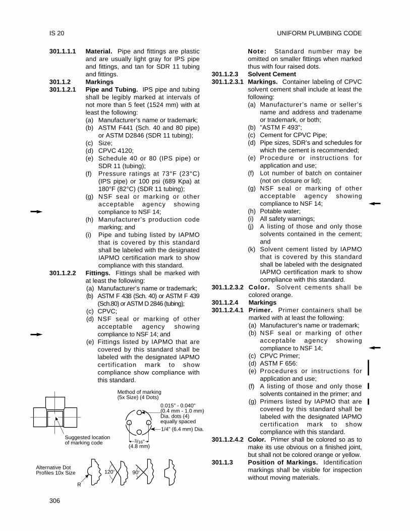
301.1.1.1 Material. Pipe and fittings are plasticand are usually light gray for IPS pipeand fittings, and tan for SDR 11 tubingand fittings.
301.1.2 Markings301.1.2.1 Pipe and Tubing. IPS pipe and tubing
shall be legibly marked at intervals ofnot more than 5 feet (1524 mm) with atleast the following:(a) Manufacturer’s name or trademark;(b) ASTM F441 (Sch. 40 and 80 pipe)
or ASTM D2846 (SDR 11 tubing);(c) Size;(d) CPVC 4120;(e) Schedule 40 or 80 (IPS pipe) or
SDR 11 (tubing);(f) Pressure ratings at 73°F (23°C)
(IPS pipe) or 100 psi (689 Kpa) at180°F (82°C) (SDR 11 tubing);
(g) NSF seal or marking or otheracceptable agency showingcompliance to NSF 14;
(h) Manufacturer’s production codemarking; and
(i) Pipe and tubing listed by IAPMOthat is covered by this standardshall be labeled with the designatedIAPMO certification mark to showcompliance with this standard.
301.1.2.2 Fittings. Fittings shall be marked withat least the following:(a) Manufacturer’s name or trademark;(b) ASTM F 438 (Sch. 40) or ASTM F 439
(Sch.80) or ASTM D 2846 (tubing);(c) CPVC;(d) NSF seal or marking of other
acceptable agency showingcompliance to NSF 14; and
(e) Fittings listed by IAPMO that arecovered by this standard shall belabeled with the designated IAPMOcertif ication mark to showcompliance show compliance withthis standard.
Note: Standard number may beomitted on smaller fittings when markedthus with four raised dots.
301.1.2.3 Solvent Cement301.1.2.3.1 Markings. Container labeling of CPVC
solvent cement shall include at least thefollowing:(a) Manufacturer’s name or seller’s
name and address and tradenameor trademark, or both;
(b) "ASTM F 493";(c) Cement for CPVC Pipe;(d) Pipe sizes, SDR’s and schedules for
which the cement is recommended;(e) Procedure or instructions for
application and use;(f) Lot number of batch on container
(not on closure or lid);(g) NSF seal or marking of other
acceptable agency showingcompliance to NSF 14;
(h) Potable water;(i) All safety warnings;(j) A listing of those and only those
solvents contained in the cement;and
(k) Solvent cement listed by IAPMOthat is covered by this standardshall be labeled with the designatedIAPMO certification mark to showcompliance with this standard.
301.1.2.3.2 Color. Solvent cements shall becolored orange.
301.1.2.4 Markings301.1.2.4.1 Primer. Primer containers shall be
marked with at least the following:(a) Manufacturer’s name or trademark;(b) NSF seal or marking of other
acceptable agency showingcompliance to NSF 14;
(c) CPVC Primer;(d) ASTM F 656:(e) Procedures or instructions for
application and use;(f) A listing of those and only those
solvents contained in the primer; and(g) Primers listed by IAPMO that are
covered by this standard shall belabeled with the designated IAPMOcertif ication mark to showcompliance with this standard.
301.1.2.4.2 Color. Primer shall be colored so as tomake its use obvious on a finished joint,but shall not be colored orange or yellow.
301.1.3 Position of Markings. Identificationmarkings shall be visible for inspectionwithout moving materials.
UNIFORM PLUMBING CODE
306
IS 20
Suggested locationof marking code
Method of marking(5x Size) (4 Dots)
Alternative DotProfiles 10x Size
R
3/16"
120o 90o
0.015" - 0.040"(0.4 mm - 1.0 mm)Dia. dots (4)equally spaced1/4" (6.4 mm) Dia.
(4.8 mm)
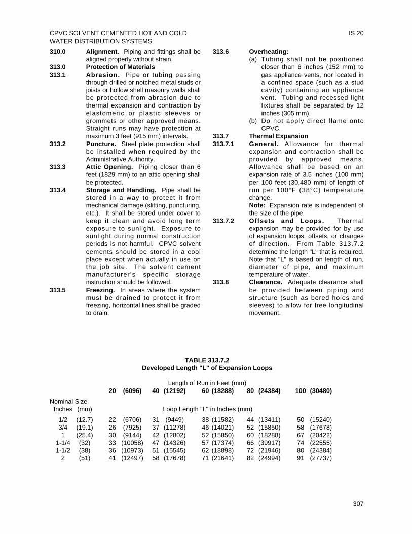
310.0 Alignment. Piping and fittings shall bealigned properly without strain.
313.0 Protection of Materials313.1 Abrasion. Pipe or tubing passing
through drilled or notched metal studs orjoists or hollow shell masonry walls shallbe protected from abrasion due tothermal expansion and contraction byelastomeric or plastic sleeves orgrommets or other approved means.Straight runs may have protection atmaximum 3 feet (915 mm) intervals.
313.2 Puncture. Steel plate protection shallbe installed when required by theAdministrative Authority.
313.3 Attic Opening. Piping closer than 6feet (1829 mm) to an attic opening shallbe protected.
313.4 Storage and Handling. Pipe shall bestored in a way to protect i t frommechanical damage (slitting, puncturing,etc.). It shall be stored under cover tokeep it clean and avoid long termexposure to sunlight. Exposure tosunlight during normal constructionperiods is not harmful. CPVC solventcements should be stored in a coolplace except when actually in use onthe job site. The solvent cementmanufacturer’s specif ic storageinstruction should be followed.
313.5 Freezing. In areas where the systemmust be drained to protect i t fromfreezing, horizontal lines shall be gradedto drain.
313.6 Overheating:(a) Tubing shall not be posit ioned
closer than 6 inches (152 mm) togas appliance vents, nor located ina confined space (such as a studcavity) containing an appliancevent. Tubing and recessed lightfixtures shall be separated by 12inches (305 mm).
(b) Do not apply direct f lame ontoCPVC.
313.7 Thermal Expansion313.7.1 General. Allowance for thermal
expansion and contraction shall beprovided by approved means.Allowance shall be based on anexpansion rate of 3.5 inches (100 mm)per 100 feet (30,480 mm) of length ofrun per 100°F (38°C) temperaturechange.Note: Expansion rate is independent ofthe size of the pipe.
313.7.2 Offsets and Loops. Thermalexpansion may be provided for by useof expansion loops, offsets, or changesof direction. From Table 313.7.2determine the length "L" that is required.Note that "L" is based on length of run,diameter of pipe, and maximumtemperature of water.
313.8 Clearance. Adequate clearance shallbe provided between piping andstructure (such as bored holes andsleeves) to allow for free longitudinalmovement.
CPVC SOLVENT CEMENTED HOT AND COLDWATER DISTRIBUTION SYSTEMS
IS 20
307
TABLE 313.7.2Developed Length "L" of Expansion Loops
Length of Run in Feet (mm)20 (6096) 40 (12192) 60 (18288) 80 (24384) 100 (30480)
Nominal SizeInches (mm) Loop Length "L" in Inches (mm)
1/2 (12.7) 22 (6706) 31 (9449) 38 (11582) 44 (13411) 50 (15240)3/4 (19.1) 26 (7925) 37 (11278) 46 (14021) 52 (15850) 58 (17678)1 (25.4) 30 (9144) 42 (12802) 52 (15850) 60 (18288) 67 (20422)
1-1/4 (32) 33 (10058) 47 (14326) 57 (17374) 66 (39917) 74 (22555)1-1/2 (38) 36 (10973) 51 (15545) 62 (18898) 72 (21946) 80 (24384)
2 (51) 41 (12497) 58 (17678) 71 (21641) 82 (24994) 91 (27737)
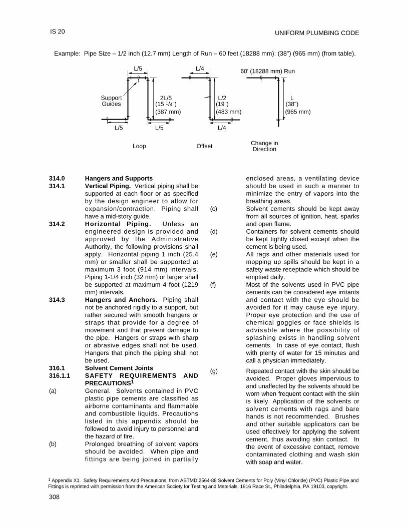
UNIFORM PLUMBING CODE
308
314.0 Hangers and Supports314.1 Vertical Piping. Vertical piping shall be
supported at each floor or as specifiedby the design engineer to allow forexpansion/contraction. Piping shallhave a mid-story guide.
314.2 Horizontal Piping. Unless anengineered design is provided andapproved by the AdministrativeAuthority, the following provisions shallapply. Horizontal piping 1 inch (25.4mm) or smaller shall be supported atmaximum 3 foot (914 mm) intervals.Piping 1-1/4 inch (32 mm) or larger shallbe supported at maximum 4 foot (1219mm) intervals.
314.3 Hangers and Anchors. Piping shallnot be anchored rigidly to a support, butrather secured with smooth hangers orstraps that provide for a degree ofmovement and that prevent damage tothe pipe. Hangers or straps with sharpor abrasive edges shall not be used.Hangers that pinch the piping shall notbe used.
316.1 Solvent Cement Joints316.1.1 SAFETY REQUIREMENTS AND
PRECAUTIONS1
(a) General. Solvents contained in PVCplastic pipe cements are classified asairborne contaminants and flammableand combustible liquids. Precautionslisted in this appendix should befollowed to avoid injury to personnel andthe hazard of fire.
(b) Prolonged breathing of solvent vaporsshould be avoided. When pipe andfittings are being joined in partially
enclosed areas, a ventilating deviceshould be used in such a manner tominimize the entry of vapors into thebreathing areas.
(c) Solvent cements should be kept awayfrom all sources of ignition, heat, sparksand open flame.
(d) Containers for solvent cements shouldbe kept tightly closed except when thecement is being used.
(e) All rags and other materials used formopping up spills should be kept in asafety waste receptacle which should beemptied daily.
(f) Most of the solvents used in PVC pipecements can be considered eye irritantsand contact with the eye should beavoided for it may cause eye injury.Proper eye protection and the use ofchemical goggles or face shields isadvisable where the possibil i ty ofsplashing exists in handling solventcements. In case of eye contact, flushwith plenty of water for 15 minutes andcall a physician immediately.
(g) Repeated contact with the skin should beavoided. Proper gloves impervious toand unaffected by the solvents should beworn when frequent contact with the skinis likely. Application of the solvents orsolvent cements with rags and barehands is not recommended. Brushesand other suitable applicators can beused effectively for applying the solventcement, thus avoiding skin contact. Inthe event of excessive contact, removecontaminated clothing and wash skinwith soap and water.
IS 20
Loop Offset Change inDirection
L(38")
L/5 L/5
L/5
2L/5(15 1/4")
L/4
L/2(19")
SupportGuides
L/4
60' (18288 mm) Run
(965 mm)(483 mm)(387 mm)
Example: Pipe Size – 1/2 inch (12.7 mm) Length of Run – 60 feet (18288 mm): (38") (965 mm) (from table).
1 Appendix X1. Safety Requirements And Precautions, from ASTMD 2564-88 Solvent Cements for Poly (Vinyl Chloride) (PVC) Plastic Pipe andFittings is reprinted with permission from the American Society for Testing and Materials, 1916 Race St., Philadelphia, PA 19103, copyright.
316.1.1.1 Selection. Follow the manufacturer'srecommendations for type of solventcements for such condit ions astemperatures over 100°F (38°C), orhumidity over 60%.
316.1.1.2 Handling (to maintain effectiveness).Package solvent cement in containersno larger than 1 quart (1 liter). Keepsolvent cement can closed and in theshade when not in use. Keep applicatorsubmerged in solvent cement betweenapplications. Discard solvent cementwhen it thickens appreciably or gels.Solvent cement shall not be thinned.
316.1.1.3 Primer. A listed primer in compliancewith ASTM F 656-96a shall be used onall CPVC solvent cemented joints.
316.1.1.4 Size of Applicator. Applicator shouldbe about one half the pipe diameter. Donot use small applicator on large pipes.
316.1.2 ProceduresStep 1. Cut pipe square with hand saw
and mitre box, mechanicalcutoff saw or tube cutterdesigned for plastic.
Step 2. Ream and chamfer pipe (toeliminate sharp edges, beadsand all burrs).
Step 3. Clean all dirt, moisture andgrease from pipe and fittingsocket. Use a clean, dry rag.
Step 4. Check dry fit of pipe in fittings.Pipe should enter fitting socket1/4 to 3/4 of socket depth. Onlarger sizes of Sch. 80 fittings,a looser fit may be expected.This is a normal condition, andrequires care to apply anadequate amount of cement.
Step 5. Apply CPVC primer (seeSection 316.1.1.1) to inside offitt ing socket. Take care toavoid puddling.
Step 6. Apply CPVC primer to outsidesurface of pipe to depth offitting socket.
Step 7. Wait until primer surface istacky. DO NOT attempt tosoften (dissolve) the surface asis required for PVC.
Step 8. Apply a liberal coat of CPVCsolvent cement to the outsidesurface of the pipe to the depthof the fitting socket.
Step 9. Apply a light coat of CPVCsolvent cement to inside of
fitting socket. Apply a secondliberal coat of cement to thepipe end. Take particular carein cementing larger sizes ofSch. 80 fittings. Be sure allsurfaces are coated.
Step 10. While both the inside socketsurface and the outside surfaceof the pipe are WET withsolvent cement, forcefullybottom the pipe in the socket,giving the pipe a quarter turnwhile inserting, if possible.
Step 11. Hold the joint together for 10 to15 seconds to assure that thepipe remains bottomed againstthe pipe stop.
Step 12. Do not disturb the joint for atleast 30 minutes. Note: The joint is weak untilthe cement is dry. If the joint isadjusted after it is set, the jointwil l be ruined. See Table316.1.2 for recommended settime.
Step 13. Wipe excess cement from thepipe. A properly made joint willshow a bead of cement aroundits entire perimeter. Any gapsmay indicate insufficientcement.
Step 14. The system shall not bepressurized unti l the jointshave cured (set) at least aslong as recommended by themanufacturer. If the manufac-turer’s recommendation is notavailable, the following curetimes are required.
316.1.3 Prohibited Joints. Piping shall not bethreaded. Female screwed fittings, withCPVC threads, shall be prohibited.Joints made with adhesives shall beprohibited.
316.1.5 Threaded Joints. When threads arerequired, molded male adapters shall beused.
316.1.5.1 Location. CPVC threaded joints shallbe accessible.
316.1.5.2 Lubricants. Only thread tape or threadlubricant approved specifically for usewith CPVC shall be used. Conventionalpipe thread compounds, putty, linseedoil based products, and unknownmixtures are prohibited.
CPVC SOLVENT CEMENTED HOT AND COLDWATER DISTRIBUTION SYSTEMS
IS 20
309
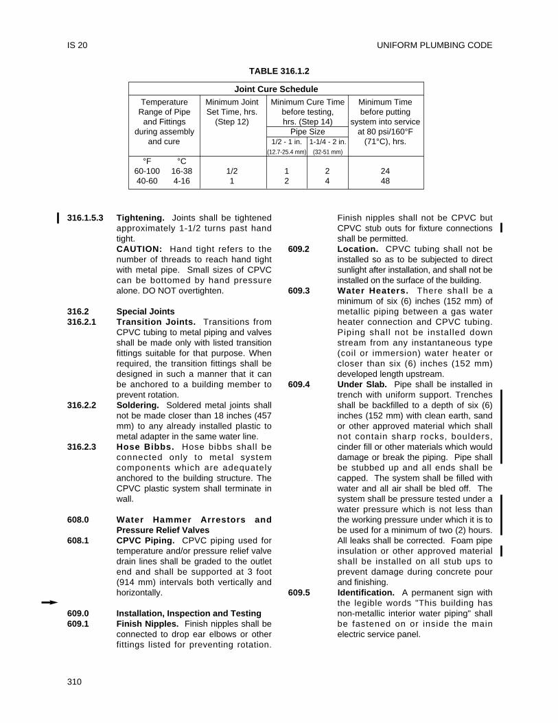
316.1.5.3 Tightening. Joints shall be tightenedapproximately 1-1/2 turns past handtight.CAUTION: Hand tight refers to thenumber of threads to reach hand tightwith metal pipe. Small sizes of CPVCcan be bottomed by hand pressurealone. DO NOT overtighten.
316.2 Special Joints316.2.1 Transition Joints. Transitions from
CPVC tubing to metal piping and valvesshall be made only with listed transitionfittings suitable for that purpose. Whenrequired, the transition fittings shall bedesigned in such a manner that it canbe anchored to a building member toprevent rotation.
316.2.2 Soldering. Soldered metal joints shallnot be made closer than 18 inches (457mm) to any already installed plastic tometal adapter in the same water line.
316.2.3 Hose Bibbs. Hose bibbs shall beconnected only to metal systemcomponents which are adequatelyanchored to the building structure. TheCPVC plastic system shall terminate inwall.
608.0 Water Hammer Arrestors andPressure Relief Valves
608.1 CPVC Piping. CPVC piping used fortemperature and/or pressure relief valvedrain lines shall be graded to the outletend and shall be supported at 3 foot(914 mm) intervals both vertically andhorizontally.
609.0 Installation, Inspection and Testing609.1 Finish Nipples. Finish nipples shall be
connected to drop ear elbows or otherfittings listed for preventing rotation.
Finish nipples shall not be CPVC butCPVC stub outs for fixture connectionsshall be permitted.
609.2 Location. CPVC tubing shall not beinstalled so as to be subjected to directsunlight after installation, and shall not beinstalled on the surface of the building.
609.3 Water Heaters. There shall be aminimum of six (6) inches (152 mm) ofmetallic piping between a gas waterheater connection and CPVC tubing.Piping shall not be installed downstream from any instantaneous type(coil or immersion) water heater orcloser than six (6) inches (152 mm)developed length upstream.
609.4 Under Slab. Pipe shall be installed intrench with uniform support. Trenchesshall be backfilled to a depth of six (6)inches (152 mm) with clean earth, sandor other approved material which shallnot contain sharp rocks, boulders,cinder fill or other materials which woulddamage or break the piping. Pipe shallbe stubbed up and all ends shall becapped. The system shall be filled withwater and all air shall be bled off. Thesystem shall be pressure tested under awater pressure which is not less thanthe working pressure under which it is tobe used for a minimum of two (2) hours.All leaks shall be corrected. Foam pipeinsulation or other approved materialshall be installed on all stub ups toprevent damage during concrete pourand finishing.
609.5 Identification. A permanent sign withthe legible words "This building hasnon-metallic interior water piping" shallbe fastened on or inside the mainelectric service panel.
UNIFORM PLUMBING CODE
310
IS 20
TABLE 316.1.2
Joint Cure ScheduleTemperature Minimum Joint Minimum Cure Time Minimum Time
Range of Pipe Set Time, hrs. before testing, before puttingand Fittings (Step 12) hrs. (Step 14) system into service
during assembly Pipe Size at 80 psi/160°Fand cure 1/2 - 1 in. 1-1/4 - 2 in. (71°C), hrs.
(12.7-25.4 mm) (32-51 mm)
°F °C60-100 16-38 1/2 1 2 2440-60 4-16 1 2 4 48
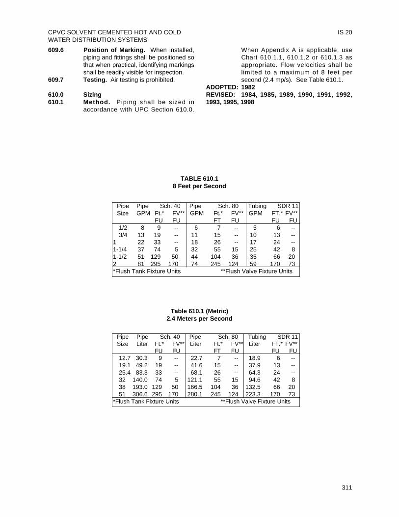
609.6 Position of Marking. When installed,piping and fittings shall be positioned sothat when practical, identifying markingsshall be readily visible for inspection.
609.7 Testing. Air testing is prohibited.
610.0 Sizing610.1 Method. Piping shall be sized in
accordance with UPC Section 610.0.
When Appendix A is applicable, useChart 610.1.1, 610.1.2 or 610.1.3 asappropriate. Flow velocities shall belimited to a maximum of 8 feet persecond (2.4 mp/s). See Table 610.1.
ADOPTED: 1982REVISED: 1984, 1985, 1989, 1990, 1991, 1992,1993, 1995, 1998
CPVC SOLVENT CEMENTED HOT AND COLDWATER DISTRIBUTION SYSTEMS
IS 20
311
TABLE 610.18 Feet per Second
Table 610.1 (Metric)2.4 Meters per Second
Pipe Pipe Sch. 40 Pipe Sch. 80 Tubing SDR 11Size Liter Ft.* FV** Liter Ft.* FV** Liter FT.* FV**
FU FU FT FU FU FU12.7 30.3 9 -- 22.7 7 -- 18.9 6 --19.1 49.2 19 -- 41.6 15 -- 37.9 13 --25.4 83.3 33 -- 68.1 26 -- 64.3 24 --32 140.0 74 5 121.1 55 15 94.6 42 838 193.0 129 50 166.5 104 36 132.5 66 2051 306.6 295 170 280.1 245 124 223.3 170 73
*Flush Tank Fixture Units **Flush Valve Fixture Units
Pipe Pipe Sch. 40 Pipe Sch. 80 Tubing SDR 11Size GPM Ft.* FV** GPM Ft.* FV** GPM FT.* FV**
FU FU FT FU FU FU1/2 8 9 -- 6 7 -- 5 6 --3/4 13 19 -- 11 15 -- 10 13 --
1 22 33 -- 18 26 -- 17 24 --1-1/4 37 74 5 32 55 15 25 42 81-1/2 51 129 50 44 104 36 35 66 202 81 295 170 74 245 124 59 170 73*Flush Tank Fixture Units **Flush Valve Fixture Units
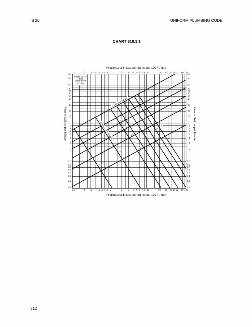
UNIFORM PLUMBING CODE
312
IS 20
Plastic SDR IITubing
Very SmoothC = 150
Friction Loss in Lbs. per Sq. In. per 100 Ft. Run
Flow
in Gallons per M
inute
Flow
in Gallons per M
inute
Friction Loss in Lbs. per Sq. In. per 100 Ft. Run
0.2
0.3
0.4
0.50.60.70.8
1.0
2
3
4
5
67
108
15
20
30
40
50607080
100
150
200
0.2
0.3
0.4
0.50.60.70.8
1.0
2
3
4
5
67
108
15
20
30
40
50607080
100
150
2000.1 .2 .3 .4 .5 .6 .7 .8 1 2 3 4 5 6 7 8 10 20 30 40 50 60 80 100
0.1 .2 .3 .4 .5 .6 .7 .8 1 2 3 4 5 6 7 8 10 20 30 40 50 60 80 100
5
2
8
7
6
4
5
3
1
1-1/2
1-1/4
1
3/4
1/2
Velocity Ft. Per Second
2 Diameter Inches
CHART 610.1.1
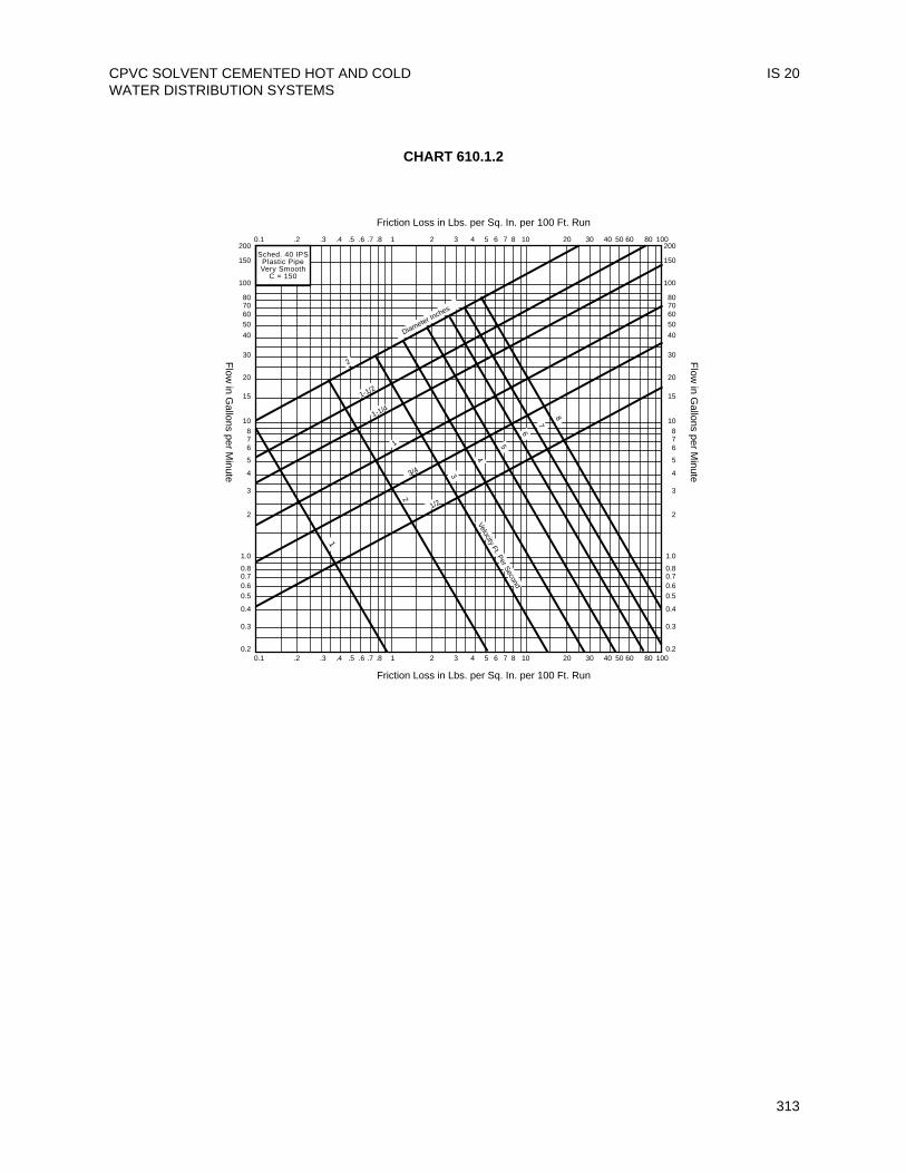
CPVC SOLVENT CEMENTED HOT AND COLDWATER DISTRIBUTION SYSTEMS
IS 20
313
Sched. 40 IPSPlastic PipeVery Smooth
C = 150
Friction Loss in Lbs. per Sq. In. per 100 Ft. RunF
low in G
allons per Minute
Flow
in Gallons per M
inuteFriction Loss in Lbs. per Sq. In. per 100 Ft. Run
0.2
0.3
0.4
0.50.60.70.8
1.0
2
3
4
5
67
108
15
20
30
40
50607080
100
150
200
0.2
0.3
0.4
0.50.60.70.8
1.0
2
3
4
5
67
108
15
20
30
40
50607080
100
150
2000.1 .2 .3 .4 .5 .6 .7 .8 1 2 3 4 5 6 7 8 10 20 30 40 50 60 80 100
0.1 .2 .3 .4 .5 .6 .7 .8 1 2 3 4 5 6 7 8 10 20 30 40 50 60 80 100
2
8
5
3
1-1/2
Diameter Inches
1-1/4
3/4
1/2
1
4
72
1
6
Velocity Ft. Per Second
CHART 610.1.2
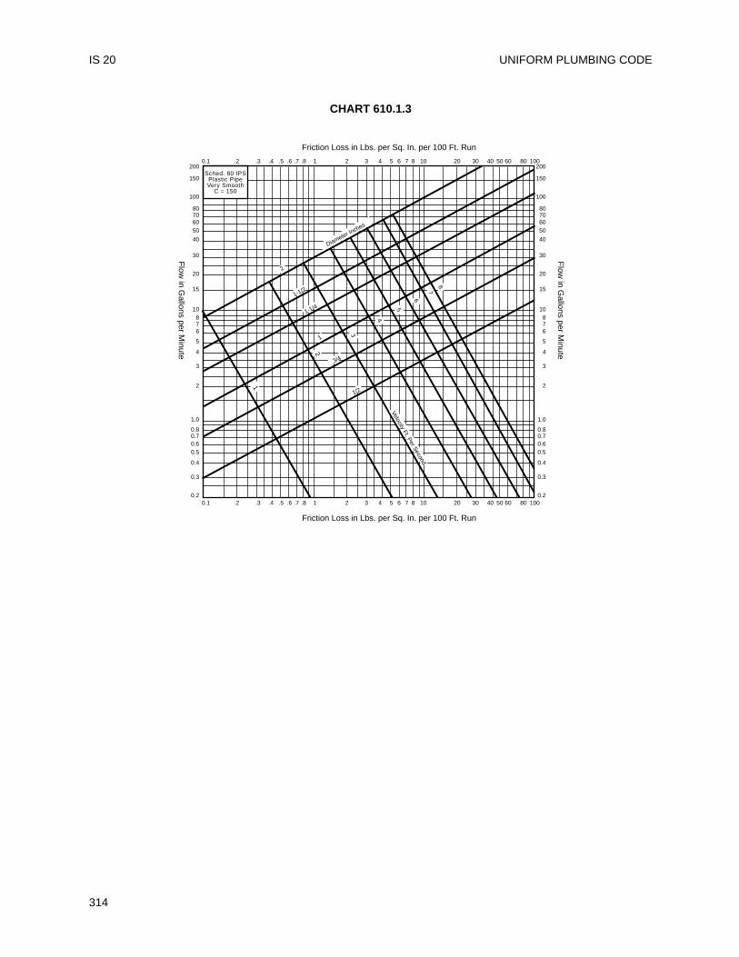
UNIFORM PLUMBING CODE
314
IS 20
CHART 610.1.3
Sched. 80 IPSPlastic PipeVery Smooth
C = 150
Friction Loss in Lbs. per Sq. In. per 100 Ft. Run
Flow
in Gallons per M
inute
Flow
in Gallons per M
inute
Friction Loss in Lbs. per Sq. In. per 100 Ft. Run
0.2
0.3
0.4
0.50.60.70.8
1.0
2
3
4
5
67
108
15
20
30
40
50607080
100
150
200
0.2
0.3
0.4
0.50.60.70.8
1.0
2
3
4
5
67
108
15
20
30
40
50607080
100
150
2000.1 .2 .3 .4 .5 .6 .7 .8 1 2 3 4 5 6 7 8 10 20 30 40 50 60 80 100
0.1 .2 .3 .4 .5 .6 .7 .8 1 2 3 4 5 6 7 8 10 20 30 40 50 60 80 100
8
5
3
1-1/2
1-1/4
3/4
1/2
4
7
2
1
6
Velocity Ft. Per Second
1
Diameter Inches
2
This standard shall govern the installation ofwelded copper and copper alloy water tube inpotable hot and cold water systems. Installation,material and inspection shall comply with the currentedition of the UPC published by the InternationalAssociation of Plumbing and Mechanical Officialsand this standard.
Note: The following sections of the UniformPlumbing Code apply to welded copper and copperalloy water tube.
Table 14-1 StandardsANSI B 16.18-84 Cast Copper Alloy Solder-Joint
Pressure Fittings
ANSI B 16.22-95 Wrought Copper and CopperAlloy Solder Joint PressureFittings
ASTM B 447-97 Standard Specification forWelded Copper Tube
ASTM B 642-88e1 Welded Copper Alloy UNS No.C21000 Water Tube
301.1 Minimum Standards903.2 Use of Copper Tubing811.1 Chemical or Industrial Waste604.2 Water piping604.3 Marking of Tubing604.4 Flexible Water Connectors310.0 Workmanship311.0 Prohibited fittings and practices313.0 Protection of Piping, Materials and
Structures314.0 Hangers and Supports Vertical
Plumbing314.0 Hangers and Supports Horizontal
Plumbing314.0 Hangers and Anchors
103.5.3 Test316.1 Types of Joints
316.1.2 Wiped Joints316.1.3 Solder and Sweat Joints606.1.1 Flared Joints606.2.1 Use of Joints, Copper Water Tube
316.2 Special Joints316.2.1 Copper Tubing to Screw Pipe
Joints705.3.3 Ground Joint, Flared or Ferrule
Connections317.0 Increasers and Reducers
Chapter 6 Water Distribution604.0 Materials604.1 Materials, Water Pipe and Fittings604.7 Restriction of Used Piping608.0 Relief Valve Drains609.0 Installation, Inspection, and
Testing610.0 Size of Portable Water Piping
Appendix A Chart A-4 Friction Loss
301.1 Minimum Standards301.1.1 Materials. Materials shall comply with the
appropriate standard in Table 14-1 of theUPC.Note: The nominal or standard size ofcopper and copper alloy welded watertube is always 0.125 inch (3.8 mm) or 1/8inch (3.8 mm) smaller than the actualoutside diameter dimension of the tube.For example, 3 inch (76 mm) nominal sizecopper plumbing, tube measures 3-1/8inch (79.2 mm) O.D., 1/2 inch (12.7 mm)nominal size copper plumbing tubemeasures 5/8 inch (15.9 mm) O.D., etc.
903.2 Use of Copper Tubing903.2.1 Markings. Markings shall be visible for
inspection.903.2.1.1 Water tube shall bear the following incised
marked at not over 18 inch (457 mm)intervals:(a) Manufacturer’s name or trademark;(b) Tube Type; and(c) Country of origin.
903.2.1.2 All hard drawn tube shall be identifiedthroughout its entire length by a coloredmarking not less than 3/16 inch in height,including legend repeated at intervals notgreater than 3 feet (914 mm). The legendshall include the type of tube, welded,ASTM specification, name or trademark ofthe manufacturer or both, and the countryof origin.(a) Tube listed by IAPMO that is covered
by this standard shall be labeled withthe designated IAPMO certificationmark to show compliance with thisstandard.
315
Installation StandardFor
WELDED COPPER AND COPPER ALLOY WATER TUBE
IAPMO IS 21-89e1
316.1 Joints316.1.1 General Information. Copper tube and
fittings maybe joined in a number of ways,depending on the purpose of the system.Soldering and brazing with capil laryfittings are the methods used most.The American Welding Society definessoldering as a joining process which takesplace below 840°F (449°C) and brazing asa similar process which occurs above840°F (449°C) but below the melting pointof the base metals. In actual practice forcopper systems, most soldering is done attemperatures ranging from about 350°F to550°F (177° to 288°C), while most brazingis done at temperatures ranging from1100° F to 1500°F (593°C to 816°C). Thechoice between soldering or brazing willgenerally depend on operating conditions.Solder joints are generally used where theservice temperature does not exceed205°F (96°C), while brazed joints can beused where greater strength is required,or where system temperatures are as highas 400°F (204°C).
316.1.1.1 Fittings for Soldered, Brazed, andFlared Joints. Fittings are available in allstandard tube sizes and in a wide varietyof types to cover needs for plumbing. Theycan be either soldered or brazed, althoughbrazing cast fittings requires care. Wroughtcopper pressure fittings are also availableover a wide range of sizes and types.These, too, can be joined by eithersoldering or brazing and wrought fittingsare preferred where brazing is the joiningmethod. Otherwise, the choice betweencast and wrought fittings is largely a matterof the user’s preference. Flared-tubefittings provide metal-to-metal contactsimilar to ground joint unions; both can beeasily taken apart and reassembled. Theyare especially useful where residual watercannot be removed from the tube andsoldering is difficult. Flared joints may berequired where a fire hazard exists and theuse of a torch to make soldered or brazedjoints is not allowed.
316.1.1.2 SoldersNote: Users of the Uniform PlumbingCodes are reminded that provisions of theFederal Clean Drinking Act of 1986, whichall must obey, forbid the use of solderwhich contains in excess of 0.2% of lead,by weight in potable water systems. Theprovisions of the act are incorporated in all
ordinances, statutes, state and municipalregulations by reference and by operationof law.The selection of a solder depends on theoperating pressure and temperature of theline. Consideration should also be given tothe stresses on the joint caused bythermal expansion and contraction.However, stresses due to temperaturechanges should not be significant in twocommonly encountered cases: when tubelengths are short, or when expansionloops are used in long tube runs.Solder is generally used in wire form, butpaste-type solders are also available. Theseare finely granulated solders in suspension ina paste flux. When using paste-type solders,observe these four rules:1. Wire solder must be applied in
addition to the paste to fill the voidsand assists in displacing the flux,otherwise the surfaces may be well"tinned" and yet there may not be agood joint with a continuous bond.
2. The paste mixture must be thoroughlystirred if it has been standing in thecan for more than a very short time,as the solder has a tendency to settlerapidly to the bottom.
3. The flux cannot be depended on toclean the tube. Cleaning should bedone manually as is recommendedfor any other flux and solder.
4. Remove any excess flux.Solders are available containing smallamounts of silver or other additives toimpart special properties. Such soldersmay require special f luxes. Themanufacturer’s recommendations shouldbe consulted regarding proper proceduresand fluxes for such solders and about theexpected properties.
316.1.1.3 Soldering FluxThe functions of the soldering flux are toremove residual traces of oxides, topromote wetting and to protect thesurfaces to be soldered from oxidationduring heating. The flux should be appliedto clean surfaces and only enough shouldbe used to lightly coat the areas to bejoined.An oxide fi lm may reform quickly oncopper after i t has been cleaned.Therefore, the flux should be applied assoon as possible after cleaning.
UNIFORM PLUMBING CODE
316
IS 21
CAUTIONCareless workmanship, especially duringflux applications, can result in corrosion ofthe tube long after the system has beeninstalled. If excessive flux is used, theresidue inside the tube can causecorrosion. In an extreme case, suchresidual f lux can actually lead toperforation through the tubewall causingleakage. To guard against this danger, itis important (1) to choose a flux that is nottoo corrosive, and (2) to use only theminimum amount actually needed tomake the joint.
316.1.2 Solder JointsSoldering and brazing both involve basicsteps, which must be executed with careand craftsmanship. The steps are:(1) Measuring(2) Cutting(3) Reaming(4) Cleaning(5) Fluxing(6) Assembly and Support(7) Heating(8) Applying the filler metal(9) Cooling and cleaningEach step contributes to a strong,dependable joint.
316.1.2.1 MeasuringMeasuring the length of each tubesegment must be accurate. Inaccuracycan compromise joint quality. If the tube istoo short it will not reach all the way intothe socket of the fitting and a proper jointcannot be made. If the tube segment istoo long, there is danger of cocking thetube in the fitting and putting strain on thesystem which could affect service life.
316.1.2.2 CuttingOnce the tube is measured it can be cut.Cutting can be accomplished in a numberof different ways to produce a satisfactorysquare end. The tube can be cut with adisc-type tube cutter, a hacksaw, anabrasive wheel, or with a stationary orportable bandsaw. Care must be takenthat the tube is not deformed while beingcut. Regardless of method, the cut mustbe square with the run of the tube so thatthe tube will seat properly in the fittingsocket.
316.1.2.3 ReamingAll pipe and tube shall be reamed to thefull I.D. of the pipe and tube.Tools used to ream tube ends include the
reaming blade on the tube cutter, half-round or round files, a pocket knife and asuitable deburring tool. With annealedtube, care must be taken not to deform thetube end by applying too much pressure.Both the inside and the outside of the tubemay require removal of the burr.
316.1.2.4 CleaningThe removal of oxides and surface soil iscrucial if filler metal is to flow properly intothe joint. Unremoved oxide, surface soiland oil can interfere with the strength ofthe joint and cause failure.Mechanical cleaning is a simple operation.The end of the tube should be abradedlightly using sand cloth or nylon abrasivepads for a distance only slightly more thanthe depth of the fitting socket. The socketof the fitting should also be cleaned usingsand cloth, abrasive pads, or a properlysized fitting brush.Copper is a relatively soft metal. If toomuch material is removed, a loose fit willresult and interfere with satisfactorycapillary action in making the joint. Thecapillary space between the tube andfitting is approximately 0.004 inch (0.1mm). Solder or brazing filler metal can fillthis gap by capillary action. This spacingis critical for the filler metal to flow into thegap and form a strong joint.Surfaces, once cleaned, should not betouched with bare hands or oily gloves.Skin oils, lubricating oils and greaseimpair solder flow and wetting.
316.1.2.5 FluxingStir the flux before use. A good flux willdissolve and remove traces of oxide fromthe cleaned surfaces to be joined, protectthe cleaned surfaces from reoxidationduring heating and promote wetting of thesurfaces by the solder. A thin, evencoating of flux should be applied with abrush to both tube and fitting. Do not applywith fingers. Chemicals in the flux can beharmful if carried to the eyes or open cuts.
316.1.2.6 Assembly and SupportAfter both tube and fitting surfaces areproperly f luxed, they should beassembled, making sure the tube seatsagainst the base of the fitting socket. Aslight twisting motion ensures evendistribution by the flux. Remove excessflux. Care must be taken to assure that thetube and fittings are properly supportedwith a uniform capillary space around the
WELDED COPPER AND COPPER ALLOY WATER TUBE IS 21
317
UNIFORM PLUMBING CODE
318
entire circumference of the joint.Uniformity of capillary space will ensuregood fi l ler metal penetration if theguidelines of successful joint making arefollowed. Excessive joint clearance cancause the filler metal to crack under stressor vibration.The joint is now ready for soldering. Jointsprepared and ready for soldering shouldbe completed the same day and not leftunfinished overnight.
316.1.2.7 HeatingBecause an open flame may be used forsoldering, and because flammable gasesare used, safety precautions must beobserved. The heat is generally appliedusing an air/fuel torch. Such torches useacetylene or an LP gas. Electricresistance tools can also be used.Heating should begin with the flameperpendicular to the tube. The coppertube conducts the initial heat into thefitting socket for even distribution of heatinside and out. The extent of thispreheating depends upon the size of thejoint. Experience will indicate the amountof time needed. The flame should now bemoved onto the fitting. Then move theflame from the fitting socket back onto thetube a distance equal to the depth of thefitting socket. Touch the solder to the joint.If the solder does not melt, remove it andcontinue the heating process. Be carefulnot to overheat or to direct the flame intothe fitting cup. This could cause the flux toburn and destroy its effectiveness. Whenthe melting temperature of the solder hasbeen reached, heat may be applied to thebase of the cup to aid capillary action indrawing the solder into the cup.
316.1.2.8 Applying the Filler MetalFor tube in a horizontal position, startapplying the solder slightly off-center atthe bottom of the joint. Proceed across thebottom of the fitting and up to the topcenter position. Return to the point ofbeginning, overlap the starting point, andthen proceed up the incompleted side tothe top, again, overlapping the solder.For joints in the vertical position, a similarsequence of overlapping passes shouldbe made, starting wherever is convenient.Molten solder will be drawn into the jointby capillary action regardless of whetherthe solder is being fed upward, downwardor horizontally.
316.1.2.9 Cooling and CleaningAfter the joint has been completed, naturalcooling is best. Shock cooling with watermay cause unnecessary stress on thejoint and result in eventual failure. Whencool, clean off any remaining flux with awet rag.
316.1.3 Brazed JointsBrazing is the second most commonlyused method for joining copper tube.Making brazed joints is similar to makingsoldered joints with respect to measuring,cutting, reaming, cleaning, assembly andsupport. And as in soldering, the brazingfiller metal is melted by the heat of thetube and fitting and drawn into the joint bycapillary action.The major differences between solderingand brazing are the:• Type of flux used,• Composition of filler metal, and• Amount of heat required to melt the fillermetal.
316.1.3.1 Brazing FluxThe fluxes used for brazing copper jointsare different in composition from solderingfluxes. The two types cannot be usedinterchangeably. Brazing fluxes are waterbased, whereas most soldering fluxes arepetroleum based. Similar to solderingfluxes, brazing fluxes dissolve and removeresidual oxide from the metal surface,protect the metal from reoxidation duringheating and promote wetting of thesurfaces to be joined by the brazing fillermetal.Fluxes also provide the draftsman with anindication of temperature. Application ofthe flux is the same as when soldering. Ifthe outside of the fitting and the heat-affected area of the tube are covered withflux (in addition to the end of the tube andthe cup), oxidation will be prevented andthe appearance of the joint will be greatlyimproved.
316.1.3.2 Brazing Filler MetalsThere are two general types of brazingfiller metal used for joining copper tube.Classified according to their components,they are: BCuP (Brazing-Copper-Phosphorous) and BAg (Brazing-Silver).BCuP filler metals are preferred for joiningcopper tube and fittings. The phosphorousin them acts as a fluxing agent and thelower percentage of silver makes themrelatively low cost. When using copper
IS 21
tube, wrought copper fittings and BCuPbrazing filler metal, fluxing is optional.However, when cast fittings are brazed,flux must be used.
316.1.3.3 HeatingOxy/fuel torches are generally used forbrazing because of the highertemperatures required.Recent innovations in tip design makeair/fuel torches useful on a wider range ofsizes for brazing.When working at brazing temperatures,safety precautions must be followed andcare taken to protect both the operatorand the materials being used.The heating operation is the same as forsoldering. First preheat the tube and thenthe tube and fitting. When the filler metalstarts to melt, apply heat at the base ofthe fitting socket to help draw the brazingfiller metal in by capillary action.
316.1.3.4 Applying Brazing Filler MetalRemember to allow the heat of the joint,not the flame, to melt the filler metal. Themelted filler metal will be drawn into thejoint by capillary action. It is very importantthat the flame be in continuous motion. Itmust not be allowed to remain on any onepoint long enough to burn through thetube or fitting.If the filler metal fails to flow, or has thetendency to ball-up, it indicates either thatthere is oxide on the surfaces being joinedor that the parts to be joined are not hotenough. If the filler metal refuses to enterthe joint, the fitting cup is not hot enough.If it tends to flow over the outside of eitherpart of the joint it indicates that part isoverheated. When the joint is completed,a continuous fi l let should be visiblecompletely around the joint.Large diameter tube is more difficult to heatto the desired temperature. The use of aheating tip or rosebud may be necessary tomaintain the proper temperature over thearea being brazed. Once total heat controlis attained, follow the same proceduresused for smaller tube.
316.1.3.5 Cooling and CleaningWhen the brazed joint is finished, allow it tocool naturally. Flux residues and someoxides formed by heating can be removed bywashing with hot water and brushing with astainless steel wire brush.
606.0 Flared Joints606.1 Flared Joints with Impact Flaring
Tools:Step 1 Cut the tube to the required
length.Step 2 Remove all burrs. This is very
important to assure metal-to-metal contact.
Step 3 Slip the coupling nut over the endof the tube.
Step 4 Insert flaring tool into the tubeend.
Step 5 Drive the flaring tool by hammerstrokes, expanding the end of thetube to the desired flare. Thisrequires a few moderately lightstrokes.
Step 6 Assemble the joint by placing thefitting squarely against the flare.Engage the coupling nut with thefitting threads. Tighten with twowrenches, one on the nut andone on the fitting.
606.2 Flared Joints with Screw-Type FlaringTools:Steps 1-3 Same as for impact f laring
previously described.Step 4 Clamp the tube in the flaring
block so that the end of thetube is slightly above the faceof the block.
Step 5 Place the yoke of the flaringtool on the block so that thebeveled end of the compressorcone is over the tube end.
Step 6 Turn the compressor screwdown firmly, forming the flarebetween the chamber in theflaring block and the beveledcompressor cone.
Step 7 Remove the flaring tool. Thejoint can now be assembled asin Step 6 for impact flaring.
610.0 Sizing610.1 Velocity.
Note: There are various hydraulicformulas for the flow of water in pipe. Withhigh velocity and attendant turbulent flow,there can be excessive noise and pipingwear.The designer should aim for maximum flowvelocities in the range of 5 to 8 feet persecond (1.5 – 2.4 meters per second) tominimize noise and erosion problems. Forthe smallest tube sizes, the designer is wiseto work at the bottom of this range, as a
WELDED COPPER AND COPPER ALLOY WATER TUBE IS 21
319
maximum, to guard against local highvelocities building up due to faultyworkmanship (e.g. burrs at tube ends whichare not properly reamed) or unusuallynumerous changes in flow direction.
GENERAL INFORMATION
It is not possible to cover all the variables of aplumbing system; However, the following informationmay prove helpful:
Expansion Loops – Copper tube, like all pipingmaterials, expands and contracts with temperaturechanges. Therefore, in a copper tube systemsubjected to excessive temperature changes, the linetends to buckle or bend when it expands unlesscompensation is built into the system. Severestresses on the joints may also occur. Such stresses,buckles, or bends are prevented by the use ofexpansion joints or by installing offsets, "U" bends,coil loops, or similar arrangements in the tubeassembly. These specially shaped tube segmentstake up expansion and contraction without excessivestress. The expansion of a length of copper tubemay be calculated from the formula:
Temperature Rise (°F) x length (feet) x 12 (inches per foot) x
Expansion Coefficient (inch per inch per °F) =Expansion (inches), or
Temperature Rise (°C) x Length (meter) x 1000 (mmper meter) x Expansion Coefficient
(mm per mm per °C) = Expansion (mm).
Calculations for expansion and contraction should bebased on the average coefficient of expansion ofcopper which is 0.0000094 per degree F (1.692 x 10⁻⁵ per degree C), between 70°F and 212°F (21°C and100°C). For example, the expansion of each 100 feet(30.5 meters) of length of any size tube heated fromroom temperature (70°F) to 170°F (a 100°F (55.6°C)rise) is 1.128 inches (28.7 mm).
100°F x 100 feet x 12 inch/foot x 0.0000094inch/inch/°F = 1.128 inch, or
55.6°C x 30.48 mm x 1000 mm/m x 1.692 x 10⁻⁵
mm/mm/°C = 28.7 mmTube SupportsVertical Piping – See Section 314.0Horizontal Piping – See Section 314.0
Bending – Copper tube, properly bent, will notcollapse on the outside of the bend and will notbuckle on the inside of the bend. Tests demonstratethat the bursting strength of a bent copper tube can
be greater than it was before bending. Becausecopper is readily formed, expansion loops and otherbends necessary in an assembly are quickly andsimply made if the proper method and equipment areused. Simple hand tools employing mandrels, dies,forms, and fi l lers, or power-operated bendingmachines, are used.
Both annealed tube and bending-temper tube can bebent with hand benders. The proper size bender foreach size tube must be used. Usually the size of thetool corresponds to the nominal outside diameter ofthe tube, not the standard tube size. For a guide tothe typical bend radii, see the following bendingguide for copper tube.
ADOPTED: 1980REVISED: 1989
UNIFORM PLUMBING CODE
320
IS 21
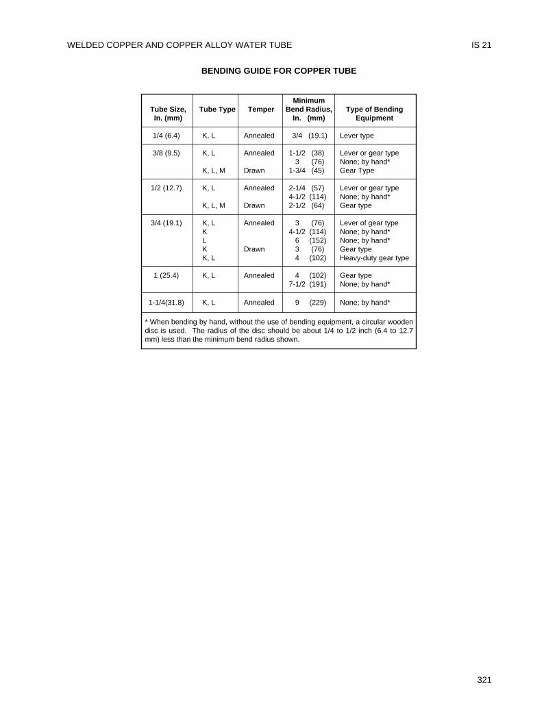
WELDED COPPER AND COPPER ALLOY WATER TUBE IS 21
321
BENDING GUIDE FOR COPPER TUBE
MinimumTube Size, Tube Type Temper Bend Radius, Type of BendingIn. (mm) In. (mm) Equipment
1/4 (6.4) K, L Annealed 3/4 (19.1) Lever type
3/8 (9.5) K, L Annealed 1-1/2 (38) Lever or gear type3 (76) None; by hand*
K, L, M Drawn 1-3/4 (45) Gear Type
1/2 (12.7) K, L Annealed 2-1/4 (57) Lever or gear type4-1/2 (114) None; by hand*
K, L, M Drawn 2-1/2 (64) Gear type
3/4 (19.1) K, L Annealed 3 (76) Lever of gear typeK 4-1/2 (114) None; by hand*L 6 (152) None; by hand*K Drawn 3 (76) Gear typeK, L 4 (102) Heavy-duty gear type
1 (25.4) K, L Annealed 4 (102) Gear type7-1/2 (191) None; by hand*
1-1/4(31.8) K, L Annealed 9 (229) None; by hand*
* When bending by hand, without the use of bending equipment, a circular woodendisc is used. The radius of the disc should be about 1/4 to 1/2 inch (6.4 to 12.7mm) less than the minimum bend radius shown.

UNIFORM PLUMBING CODE
322

This standard shall govern the TrenchlessInstallation of Polyethylene (PE) pipe for use insanitary and storm sewers. The installed pipe shallcomply with the requirements of the UniformPlumbing Code (UPC) published by the InternationalAssociation of Plumbing and Mechanical Officials(IAPMO) as to grade and connections to existing pipeand shall also comply with this standard.
Note: The following sections of the UniformPlumbing Code apply.
103.5.3 Testing of Systems103.5.4.2 Responsibility103.5.5 Other Inspections103.5.5.1 Defective Systems103.6.2 Other Connections202.0 Definition of PETable 14-1 Materials
ASTM D1412ASTM D2239ASTM D2683ASTM D2447ASTM D2657ASTM F714ASTM F894IAPMO PS 25
301.1 Minimum Standards310.0 Workmanship313.0 Protection of Piping, Materials and
Structures315.0 Backfilling316.2.3 Connection to Other MaterialsChapter 7 Sanitary Drainage701.2 Fittings
ABBREVIATIONSASTM American Society for Testing MaterialsIAPMO International Association of Plumbing and
Mechanical OfficialsUPC Uniform Plumbing Code
301.1 Minimum Standards301.1.1 Materials
Materials shall comply with the following:The Polyethylene pipe used is covered bythe ASTM standards listed later in thisstandard
ASTMMaterials StandardHDPE Extra High Molecular F714Weight 3408 SDR 17 PipeSocket-Type PE Fittings D2683for Outside Diameter-ControlledPolyethylene Pipe
Note: The HDPE 3408 SDR 17 pipe used in thisprocess was selected because of its abilityto retain its circular shape even when benton a 4 foot radius during and afterinstallation.
313.0 Protection of Pipe313.1 Storage and Handling
Pipe shall be stored in a way to protect itfrom mechanical damage (sl i t t ing,puncturing, etc.). It shall be stored undercover to keep it clean and avoid long termexposure to sunlight. Exposure to sunlightduring normal construction periods is notharmful.
705.1.0 Types of JointsPE joints shall be made as follows:
705.1.6 Molded Rubber Coupling JointsMolded rubber coupling joints shall beinstalled in accordance with Appendix I ofthe UPC.
705.1.8 Shielded Coupling JointsShielded coupling joints shall be installedin accordance with Appendix I of the UPC.
705.1.9 Hubless Cast Iron Pipe JointsHubless cast iron pipe joints shall beinstalled in accordance with Appendix I ofthe UPC.
301.1.1 Heat Fusion JointsHeat fusion joints shall be made accordingto the manufacturer’s procedure,installation instructions, and ASTM D2657.
1211.0 Trenchless Installation of sewers willbe as follows:I. Preliminary Steps:Inspect the inside of the sewer line using atelevision camera and video tape recorderto ascertain the line condition. Mark thedetails revealed by the video inspectionincluding:1. The ground surface to show the location
of the lateral tie of the city wye.
323
Installation StandardFor
TRENCHLESS POLYETHYLENE (PE) PIPE FOR SEWER LATERALS
IAPMO IS 26-99
2. The line location with an arrow in thestreet pointing back at the lateral.
3. The property denoting the laterallocation.
4. The locations of the proposedexcavations.
Obtain utility line identification servicecontact information and all applicablepermits.II. ExcavationIn addition to the above markings, thelocal utility companies will mark utilities.Considerations are soil density; clearancefrom obstacles, utilities, and structures;location of bends; and water servicelocations. Excavations and shoring shallbe in accordance with jurisdictional safetyrequirements.III. Set UpFuse the proper length of polyethylenepipe in accordance with ASTM D 3261 andfuse the end to a small length that isattached to the pulling head. A rod pushercable is pushed through the damaged hostpipe and attached to the pulling cable,which is then drawn through the pipe. Theclevis end of the cable is attached to thepulling head. The resistance plate isplaced over the cut off end of the pipe andcable and centered on the open end of theold, or host pipe. The pulley assembly isset against the resistance plate and thepulling ram is set atop of the pulleyassembly by inserting the nose of the raminto the annulus of the pulley assembly.The 5/8 or 3/4 cable is strung around thepulley, through the ram collets and the ramis rotated 1/4 turn to lock the cable inplace. Complete the above before startingthe pull.IV. PullingPull the pulling head through. Once thepull is done, complete the connection tothe existing piping.
707 CleanoutsCleanouts shall be installed in accordancewith UPC section 707.
103.5 Inspections:The completed piping shall be internallyinspected by television camera unlesswaived by the Administrative Authority.
712.0 Testing:Completed piping shall be subjected totesting in accordance with section 712.0or 723.0 of the UPC.
UNIFORM PLUMBING CODE
324
IS 26
J 1 Reclaimed Water Systems – General
(a) The provisions of this appendix shall apply tothe installation, construction, alteration, and repair ofreclaimed water systems intended to supply waterclosets, urinals, and trap primers for floor drains andfloor sinks. Use is limited to these fixtures that arelocated in non-residential buildings. Fixtures withinresidential buildings are excluded from the list ofapproved uses. The reclaimed water system shallhave no connection to any potable water system,with or without mechanical backflow preventiondevices. If reclaimed water is utilized on thepremises, all potable water supplies shall beprovided with appropriate backflow protection, asrequired by the authority having jurisdiction. Exceptas otherwise provided for in this appendix, theprovisions of this Code shall be applicable toreclaimed water system installations.
(b) No permit for any reclaimed water system shallbe issued until complete plumbing plans, withappropriate data satisfactory to the AdministrativeAuthority, have been submitted and approved. Nochanges or connections shall be made to either thereclaimed water system or the potable water systemwithin any site containing a reclaimed water system,without approval by the Administrative Authority.
(c) Before the building may be occupied, theinstaller shall perform the initial cross-connectiontest in the presence of the Administrative Authorityand other authorities having jurisdiction, and the testshall be ruled successful by the AdministrativeAuthority before final approval is granted.
J 2 Definitions
Reclaimed water is water which, as a result oftertiary treatment of domestic wastewater by apublic agency, is suitable for a direct beneficial useor a controlled use that would not otherwise occur.The level of treatment and quality of the reclaimedwater shall be approved by the public healthauthority having jurisdiction.
For the purpose of this appendix, tertiarytreatment shall result in water which is adequatelyoxidized, clarified, coagulated, filtered anddisinfected, so that at some location in the treatmentprocess, the seven- (7) day median number of totalcoliform bacteria in daily samples does not exceedtwo and two tenths (2.2) per one hundred (100)milliliters, and the number of total coliform bacteria
does not exceed twenty-three (23) per one hundred(100) milliliters in any sample. The water shall befiltered so that the daily average turbidity does notexceed two (2) turbidity units upstream from thedisinfection process.
Specifically excluded from this definition is“graywater,” which is defined in Appendix G of thisCode.
J 3 Permit
It shall be unlawful for any person to construct,install, alter, or cause to be constructed, installed, oraltered any reclaimed water system within abuilding or on a premise without first obtaining apermit to do such work from the AdministrativeAuthority.
J 4 Drawings and Specifications
The Administrative Authority may require any or allof the following information to be included with orin the plot plan before a permit is issued for areclaimed water system.
(a) A plot plan drawn to scale: completelydimensioned; showing lot lines; structures; locationof all present and proposed potable water supplyand meters, water wells, streams, auxiliary watersupply and systems, reclaimed water supply andmeters; drain lines; and locations of private sewagedisposal systems and one hundred (100) percentexpansion areas, or building sewer connected to thepublic sewer.
(b) Details of construction, including riser diagramsor isometrics, and a full description of the completeinstallation, including installation methods,construction and materials as required by theAdministrative Authority. To the extent permittedby structural conditions, all reclaimed water riserswithin the toilet room, including appurtenances suchas air/vacuum relief valves, pressure reducingvalves, etc., shall be installed in the opposite end ofthe room containing the served fixtures from thepotable water risers, or opposite walls as applicable.To the extent permitted by structural conditions,reclaimed water headers and branches off of risersshall not be run in the same wall or ceiling cavity ofthe toilet room where potable water piping is run.
(c) Detailed initial and annual testing requirementsas outlined elsewhere in this appendix.
325
APPENDIX JRECLAIMED WATER SYSTEMS FOR NON-RESIDENTIAL BUILDINGS
J 5 Pipe Material/Pipe Identification
Reclaimed water piping and fittings shall be asrequired in this Code for potable water piping andfittings. All reclaimed water pipe and fittings shall becontinuously wrapped with purple-colored Mylartape. The wrapping tape shall have a minimumnominal thickness of five ten-thousandths (0.0005)inch (0.127 mm) and a minimum width of two (2)inches (51 mm). Tape shall be fabricated of polyvinylchloride with a synthetic rubber adhesive and a clearpolypropylene protective coating or approved equal.The tape shall be purple in color (Pantone color #512)and shall be imprinted in nominal one-half (1/2)inch (12.7 mm) high, black, uppercase letters, withthe words “CAUTION: RECLAIMED WATER, DONOT DRINK”. The lettering shall be imprinted intwo (2) parallel lines, such that after wrapping thepipe with a one-half (1/2) width overlap, one (1) fullline of text shall be visible. Wrapping tape is notrequired for buried PVC pipe manufactured withpurple color integral to the plastic and marked onopposite sides to read “CAUTION: RECLAIMEDWATER, DO NOT DRINK” in intervals not toexceed three (3) feet (914 mm).
All valves, except fixture supply control valves,shall be equipped with a locking feature. Allmechanical equipment which is appurtenant to thereclaimed water system shall be painted purple tomatch the Mylar wrapping tape.
J 6 Installation
(a) Hose bibbs shall not be allowed on reclaimedwater piping systems.
(b) The reclaimed water system and the potablewater system within the building shall be providedwith the required appurtenances (valves,air/vacuum relief valves etc.) to allow fordeactivation or drainage as may be required by J 8 ofthis appendix.
(c) Reclaimed water pipes shall not be run or laid inthe same trench as potable water pipes. A ten (10)foot (3048 mm) horizontal separation shall bemaintained between pressurized buried reclaimedand potable water piping. Buried potable waterpipes crossing pressurized reclaimed water pipesshall be laid a minimum of twelve (12) inches (305mm) above the reclaimed water pipes. Reclaimedwater pipes laid in the same trench or crossingbuilding sewer or drainage piping shall be installedin compliance with Sections 609.0 and 720.0 of thisCode. Reclaimed water pipes shall be protectedsimilar to potable water pipes.
J 7 Signs
(a) Room Entrance Signs. All installations usingreclaimed water for water closets and/or urinalsshall be identified with signs. Each sign shall containone-half (1/2) inch (12.7 mm) letters of a highlyvisible color on a contrasting background. Thelocation of the sign(s) shall be such that the sign(s)shall be visible to all users. The number and locationof the signs shall be approved by the AdministrativeAuthority and shall contain the following text:
TO CONSERVE WATER, THIS BUILDING USESRECLAIMED
WATER TO FLUSH TOILETS AND URINALS.
(b) Equipment Room Signs. Each equipment roomcontaining reclaimed water equipment shall have asign posted with the following wording in one (1)inch (25.4 mm) letters on a purple background:
CAUTIONRECLAIMED WATER, DO NOT DRINK.
DO NOT CONNECT TO DRINKING WATERSYSTEM.
NOTICECONTACT BUILDING MANAGEMENT BEFOREPERFORMING ANY WORK ON THIS WATER
SYSTEM.
This sign shall be posted in a location that isvisible to anyone working on or near reclaimedwater equipment.
(c) Where tank-type water closets are flushed withreclaimed water, the tank shall be labeled:
RECLAIMED WATER – DO NOT DRINK
(d) Valve Access Door Signs. Each reclaimedwater valve within a wall shall have its access doorinto the wall equipped with a warning signapproximately six (6) inches by six (6) inches (152mm x 152 mm) with wording in one half (1/2) inch(12.7 mm) letters on a purple background. The size,shape and format of the sign shall be substantiallythe same as that specified in subsection (b) above.The signs shall be attached inside the access doorframe and shall hang in the center of the access doorframe. This sign requirement shall be applicable toany and all access doors, hatches, etc. leading toreclaimed water piping and appurtenances.
(e) Valve Seals. Each valve or appurtenance shallbe sealed in a manner approved by theAdministrative Authority after the reclaimed systemhas been approved, and placed into operation. Theseseals shall either be a crimped lead wire seal, or aplastic break-away seal which, if broken after systemapproval, shall be deemed conclusive evidence that
UNIFORM PLUMBING CODE
326
Appendix J
the reclaimed water system has been accessed. Theseals shall be purple with the words “RECLAIMEDWATER”, and shall be supplied by the reclaimedwater purveyor, or by other arrangements acceptableto the Administrative Authority.
J 8 Inspection and Testing
(a) Reclaimed water piping shall be tested asoutlined in this Code for testing of potable waterpiping.
(b) An initial and subsequent annual cross-connection inspection and test shall be performed onboth the potable and reclaimed water systems asfollows:
(1) Visual Dual System Inspection. Prior tocommencing the cross-connection testing, a dualsystem inspection shall be conducted by theAdministrative Authority and other authoritieshaving jurisdiction.
(i) Meter locations of the reclaimed waterand potable water lines shall be checked toverify that no modifications were made, orcross-connections are visible.
(ii) All pumps and equipment, equipmentroom signs, and exposed piping inequipment room shall be checked.
(iii) All valves shall be checked to insure thatvalve lock seals are still in place and intact.All valve control door signs shall be checkedto verify that no signs have been removed.
(2) Cross-Connection Test. The followingprocedure shall be followed by the applicant inthe presence of the Administrative Authorityand other authorities having jurisdiction todetermine if a cross-connection occurred.
(i) The potable water system shall beactivated and pressurized. The reclaimedwater system shall be shut down andcompletely drained.
(ii) The potable water system shall remainpressurized for a minimum period of timespecified by the Administrative Authoritywhile the reclaimed water system is empty.The minimum period the reclaimed watersystem is to remain depressurized shall bedetermined on a case by case basis, takinginto account the size and complexity of thepotable and reclaimed water distributionsystems, but in no case shall that period beless than one (1) hour.
(iii) All fixtures, potable and reclaimed,shall be tested and inspected for flow. Flow
from any reclaimed water system outletshall indicate a cross-connection. No flowfrom a potable water outlet would indicatethat it may be connected to the reclaimedwater system.
(iv) The drain on the reclaimed watersystem shall be checked for flow during thetest and at the end of the period.
(v) The potable water system shall then becompletely drained.
(vi) The reclaimed water system shall thenbe activated and pressurized.
(vii)The reclaimed water system shallremain pressurized for a minimum periodof time specified by the AdministrativeAuthority while the potable water system isempty. The minimum period the potablewater system is to remain depressurizedshall be determined on a case by case basis,but in no case shall that period be less thanone (1) hour.
(viii)All fixtures, potable and reclaimed shallbe tested and inspected for flow. Flow fromany potable water system outlet shall indicatea cross-connection. No flow from a reclaimedwater outlet would indicate that it may beconnected to the potable water system.
(ix) The drain on the potable water systemshall be checked for flow during the test andat the end of the period.
(x) If there is no flow detected in any of thefixtures which would have indicated across-connection, the potable water systemshall be repressurized.
(3) In the event that a cross-connection isdiscovered, the following procedure, in thepresence of the Administrative Authority, shallbe activated immediately:
(i) Reclaimed water piping to the buildingshall be shut down at the meter, and thereclaimed water riser shall be drained.
(ii) Potable water piping to the buildingshall be shut down at the meter.
(iii) The cross-connection shall be uncoveredand disconnected.
(iv) The building shall be retested followingprocedures listed in subsections (b)(1) and(b)(2) above.
(v) The potable water system shall bechlorinated with fifty (50) ppm chlorine fortwenty-four (24) hours.
RECLAIMED WATER SYSTEMS Appendix J
327
(vi) The potable water system shall beflushed after twenty-four (24) hours, and astandard bacteriological test shall beperformed. If test results are acceptable, thepotable water system may be recharged.
(c) An annual inspection of the reclaimed watersystem, following the procedures listed in subsectionJ 8 (b)(1), shall be required. Annual cross-connectiontesting, following the procedures listed in subsectionJ 8 (b)(2), shall be required by the AdministrativeAuthority, unless site conditions do not require it. Inno event shall the test occur less often than once infour (4) years. Alternate testing requirements may beallowed by the Administrative Authority forinstitutional buildings.
The Health Officer or other designated appointeemay substitute for the Administrative Authority inthe above mentioned inspection and tests.
J 9 Sizing
Reclaimed water piping shall be sized as outlined inthis Code for sizing potable water piping.
J 10 Approved Uses of Reclaimed Water
Reclaimed water is allowed in all non-residentialbuildings to supply fixtures as specified in thisappendix, except where prohibited by statute,regulation, or ordinance.
UNIFORM PLUMBING CODE
328
Appendix J
K1 Private Sewage Disposal – General
(a) Where permitted by Section 713.0, the buildingsewer may be connected to a private sewage disposalsystem complying with the provisions of thisappendix. The type of system shall be determined onthe basis of location, soil porosity, and ground waterlevel and shall be designed to receive all sewagefrom the property. The system, except as otherwiseapproved, shall consist of a septic tank with effluentdischarging into a subsurface disposal field, into one(1) or more seepage pits or into a combination ofsubsurface disposal field and seepage pits. TheAdministrative Authority may grant exceptions tothe provisions of this appendix for permittedstructures which have been destroyed due to fire ornatural disaster, and which cannot be reconstructedin compliance with these provisions.
(b) Where the quantity or quality of the sewage issuch that the above system cannot be expected tofunction satisfactorily; for commercial, agricultural,and industrial plumbing systems; for installationswhere appreciable amounts of industrial orindigestible wastes are produced; for occupanciesproducing abnormal quantities of sewage or liquidwaste; or when grease interceptors are required byother parts of this Code, the method of sewagetreatment and disposal shall be first approved by theAdministrative Authority. Special sewage disposalsystems for minor, limited, or temporary uses shallbe first approved by the Administrative Authority.
(c) Disposal systems shall be designed to utilize themost porous or absorptive portions of the soilformation. Where the ground water level extends towithin twelve (12) feet (3658 mm) or less of theground surface or where the upper soil is porous andthe underlying stratum is rock or impervious soil, aseptic tank and disposal field system shall beinstalled.
(d) All private sewage disposal systems shall be sodesigned that additional seepage pits or subsurfacedrain fields, equivalent to at least one hundred (100)percent of the required original system, may beinstalled if the original system cannot absorb all thesewage. No division of the lot or erection ofstructures on the lot shall be made if such division orstructure impairs the usefulness of the one hundred(100) percent expansion area.
(e) No property shall be improved in excess of itscapacity to properly absorb sewage effluent by themeans provided in this Code.
Exception: The Administrative Authority may, athis discretion, approve an alternate system.
(f) No private sewage disposal system, or partthereof, shall be located in any lot other than the lotwhich is the site of the building or structure servedby such private sewage disposal system; nor shallany private sewage disposal system or part thereofbe located at any point having less than theminimum distances indicated in Table K-1.
Nothing contained in this Code shall beconstrued to prohibit the use of all or part of anabutting lot to provide additional space for a privatesewage disposal system or part thereof, when propercause, transfer of ownership, or change of boundarynot in violation of other requirements has been firstestablished to the satisfaction of the AdministrativeAuthority. The instrument recording such actionshall constitute an agreement with theAdministrative Authority which shall clearly stateand show that the areas so joined or used shall bemaintained as a unit during the time they are soused. Such agreement shall be recorded in the officeof the County Recorder as part of the conditions ofownership of said properties, and shall be bindingon all heirs, successors, and assigns to suchproperties. A copy of the instrument recording suchproceedings shall be filed with the AdministrativeAuthority.
(g) When there is insufficient lot area or impropersoil conditions for adequate sewage disposal for thebuilding or land use proposed, and AdministrativeAuthority so finds, no building permit shall beissued and no private sewage disposal shall bepermitted. Where space or soil conditions are critical,no building permit shall be issued until engineeringdata and test reports satisfactory to theAdministrative Authority have been submitted andapproved.
(h) Nothing contained in this appendix shall beconstrued to prevent the Administrative Authorityfrom requiring compliance with higher requirementsthan those contained herein, where such higherrequirements are essential to maintain a safe andsanitary condition.
(i) Alternate systems may be used only by specialpermission of the Administrative Authority afterbeing satisfied of their adequacy. This authorizationmay be based on extensive field and test data fromconditions similar to those at the proposed site ormay require such additional data as may be
329
APPENDIX K
PRIVATE SEWAGE DISPOSAL SYSTEMS
UNIFORM PLUMBING CODE
330
necessary to provide assurance that the alternatesystem will produce continuous and long-rangeresults at the proposed site, at least equivalent tosystems which are specifically authorized.
If demonstration systems are to be consideredfor installation, conditions for installation,maintenance, and monitoring at each such site shallfirst be established by the Administrative Authority.
Aerobic Systems. Approved aerobic systems maybe substituted for conventional septic tanks providedthe Administrative Authority is satisfied that suchsystems will produce results at least equivalent toseptic tanks, whether their aeration systems areoperating or not.
K 2 Capacity of Septic Tanks
The liquid capacity of all septic tanks shall conformto Tables K-2 and K-3 as determined by the numberof bedrooms or apartment units in dwellingoccupancies and the estimated waste/sewage designflow rate or the number of plumbing fixture units asdetermined from Table 7-3, whichever is greater inother building occupancies. The capacity of any oneseptic tank and its drainage system shall be limitedby the soil structure classification, as specified inTable K-5.
K 3 Area of Disposal Fields and Seepage Pits
The minimum effective absorption area in disposalfields in square feet (m2), and in seepage pits insquare feet (m2) of side wall, shall be predicated onthe required septic tank capacity in gallons (liters)and/or estimated waste/sewage flow rate,whichever is greater, and shall conform to Table K-4as determined for the type of soil found in theexcavation, and shall be as follows:
(1) When disposal fields are installed, aminimum of one hundred and fifty (150) squarefeet (14 m2) of trench bottom shall be providedfor each system exclusive of any hard pan, rock,clay, or other impervious formations. Side wallarea in excess of the required twelve (12) inches(305 mm) and not to exceed thirty-six (36) inches(914 mm) below the leach line may be added tothe trench bottom area when computingabsorption areas.
(2) Where leaching beds are permitted in lieu oftrenches, the area of each such bed shall be atleast fifty (50) percent greater than the tabularrequirements for trenches. Perimeter side wallarea in excess of the required twelve (12) inches(305 mm) and not to exceed thirty-six (36) inches(914 mm) below the leach line may be added to
the trench bottom area when computingabsorption areas.
(3) No excavation for a leach line or leach bedshall extend within five (5) feet (1524 mm) of thewater table nor to a depth where sewage maycontaminate the underground water stratum thatis usable for domestic purposes.
Exception: In areas where the records ordata indicate that the ground waters aregrossly degraded, the five (5) foot (1524mm) separation requirement may bereduced by the Administrative Authority.The applicant shall supply evidence ofground water depth to the satisfaction of theAdministrative Authority.
(4) The minimum effective absorption area inany seepage pit shall be calculated as theexcavated side wall area below the inletexclusive of any hardpan, rock, clay, or otherimpervious formations.
The minimum required area of porousformation shall be provided in one or moreseepage pits. No excavation shall extend withinten (10) feet (3048 mm) of the water table nor to adepth where sewage may contaminateunderground water stratum that is usable fordomestic purposes.
Exception: In areas where the records ordata indicate that the ground waters aregrossly degraded, the ten (10) foot (3048mm) separation requirement may bereduced by the Administrative Authority.
The applicant shall supply evidence ofground water depth to the satisfaction of theAdministrative Authority.
(5) Leaching chambers shall be sized on thebottom absorption area (nominal unit width) insquare feet. The required area shall be calculatedusing Table K-4 with a 0.70 multiplier.
K 4 Percolation Test
(a) Wherever practicable, disposal field and seepagepit sizes shall be computed from Table K-4. Seepagepit sizes shall be computed by percolation testsunless use of Table K-4 is approved by the Adminis-trative Authority.
(b) In order to determine the absorption qualities ofseepage pits and of questionable soils other thanthose listed in Table K-4, the proposed site shall besubjected to percolation tests acceptable to theAdministrative Authority.
(c) When a percolation test is required, no privatedisposal system shall be permitted to serve a
Appendix K
building if that test shows the absorption capacity ofthe soil is less than 0.83 gallons per square foot (33.8L/m2) or more than 5.12 gallons per square foot (208L/m2) of leaching area per 24 hours. If thepercolation test shows an absorption rate greaterthan 5.12 gallons per square foot (208 L/m2) per 24hours, a private disposal system may be permitted ifthe site does not overlie ground waters protected fordrinking water supplies, a minimum thickness oftwo (2) feet (610 mm) of the native soil below theentire proposed system is replaced by loamy sand,and the system design is based on percolation testsmade in the loamy sand.
K 5 Septic Tank Construction
(a) Plans for all septic tanks shall be submitted tothe Administrative Authority for approval. Suchplans shall show all dimensions, reinforcing,structural calculations, and such other pertinent dataas may be required.
(b) Septic tanks design shall be such as to produce aclarified effluent consistent with accepted standardsand shall provide adequate space for sludge andscum accumulations.
(c) Septic tanks shall be constructed of solid durablematerials, not subject to excessive corrosion or decayand shall be watertight.
(d) Septic tanks shall have a minimum of two (2)compartments. The inlet compartment of any septictank shall be not less than two-thirds (2/3) of thetotal capacity of the tank, nor less than five hundred(500) gallons (2.0 m3) liquid capacity, and shall be atleast three (3) feet (914 mm) in width and five (5) feet(1524 m m) in length. Liquid depth shall be not lessthan two (2) feet (610 mm) and six (6) inches (152mm) nor more than six (6) feet (1829 mm). Thesecondary compartment of any septic tank shall havea minimum capacity of two hundred fifty (250)gallons (1.0 m3) and a maximum capacity of one-third (1/3) of the total capacity of such tank. In septictanks having over fifteen hundred (1500) gallons (6.0m3) capacity, the secondary compartment may benot less than five (5) feet (1524) in length.
(e) Access to each septic tank shall be provided byat least two (2) manholes twenty (20) inches (508mm) in minimum dimension or by an equivalentremovable cover slab. One access manhole shall belocated over the inlet and one (1) access manholeshall be located over the outlet. Wherever a firstcompartment exceeds twelve (12) feet (3658 mm) inlength, an additional manhole shall be provided overthe baffle wall.
(f) The inlet and outlet pipe openings shall be notless in size than the connecting sewer pipe. The
vertical leg of a round inlet and outlet fittings shallnot be less in size than the connecting sewer pipe norless than four (4) inches (102 mm). A baffle typefitting shall have the equivalent cross-sectional areaof the connecting sewer pipe and not less than a four(4) inch (100 mm) horizontal dimension whenmeasured at the inlet and outlet pipe inverts.
(g) The inlet and outlet pipe or baffle shall extendfour (4) inches (100 mm) above and at least twelve(12) inches (305 mm) below the water surface. Theinvert of the inlet pipe shall be at a level not less thantwo (2) inches (51 mm) above the invert of the outletpipe.
(h) Inlet and outlet pipe fittings or baffles, andcompartment partitions shall have a free vent areaequal to the required cross-sectional area of thehouse sewer or private sewer discharging therein toprovide free ventilation above the water surfacefrom the disposal field or seepage pit through theseptic tank, house sewer, and stack to the outer air.
(i) The side walls shall extend at least nine (9)inches (229 mm) above the liquid depth. The cover ofthe septic tank shall be at least two (2) inches (51mm) above the back vent openings.
(j) Partitions or baffles between compartments shallbe of solid durable material and shall extend at leastfour (4) inches (102 mm) above the liquid level. Aninverted fitting equivalent in size to the tank inlet,but in no case less than four (4) inches (102 mm) insize, shall be installed in the inlet compartment sideof the baffle with the bottom of the fitting placedmidway in the depth of the liquid. Wooden bafflesare prohibited.
(k) Each such tank shall be structurally designed towithstand all anticipated earth or other loads. Allseptic tank covers shall be capable of supporting anearth load of not less than three hundred (300)pounds per square foot (14.4 kPa) when themaximum coverage does not exceed three (3) feet(914 m m).
(l) Septic tanks installed under concrete or blacktop paving shall have the required manholesaccessible by extending the manhole openings tograde in a manner acceptable to the AdministrativeAuthority.
(m) Materials
(1) Concrete Septic TanksAll materials used in constructing a septic tankshall be in accordance with applicable standardsin Chapter 14, Table 14-1.
(2) Steel Septic TanksThe minimum wall thickness of any steel septictank shall be No. 12 U.S. gauge (0.109) (2.8 mm)
PRIVATE SEWAGE DISPOSAL SYSTEMS Appendix K
331
and each such tank shall be protected fromcorrosion, both externally and internally, by anapproved bituminous coating or by otheracceptable means.
(3) Alternate Materials
(i) Septic tanks constructed of alternatematerials may be approved by theAdministrative Authority when complyingwith approved applicable standards.
(ii) Wooden septic tanks are prohibited.
(n) Prefabricated Septic Tanks
(1) Manufactured or prefabricated septic tanksshall comply with all approved applicablestandards and be approved by theAdministrative Authority.
(2) independent laboratory tests andengineering calculations certifying the tankcapacity and structural stability shall beprovided as required by the AdministrativeAuthority.
K 6 Disposal Fields
(a) Distribution lines shall be constructed of clay tilelaid with open joints, perforated clay pipe,perforated bituminous fiber pipe, perforated highdensity polyethylene pipe, perforated ABS pipe,perforated PVC pipe, or other approved materials,provided that sufficient openings are available fordistribution of the effluent into the trench area.
(b) Before placing filter material or drain lines in aprepared excavation, all smeared or compactedsurfaces shall be removed from trenches by rakingto a depth of one (1) inch (25.4 mm) and the loosematerial removed. Clean stone, gravel, slag, orsimilar filter material acceptable to theAdministrative Authority, varying in size from threefourths (3/4) inch to two and one-half (2-1/2) inches(19.1 mm to 64 mm) shall be placed in the trench tothe depth and grade required by this section. Drainpipe shall be placed on filter material in anapproved manner. The drain lines shall then becovered with filter material to the minimum depthrequired by this section and this covered withuntreated building paper, straw, or similar porousmaterial to prevent closure of voids with earthbackfill. No earth backfill shall be placed over thefilter material cover until after inspection andacceptance.
Exception: Listed or approved plastic leachingchambers may be used in lieu of pipe and filtermaterial. Chamber installations shall follow therules for disposal fields, where applicable, and
shall conform to manufacturer’s installationinstructions.
(c) A grade board staked in the trench to the depthof filter material shall be utilized when distributionline is constructed with drain tile or a flexible pipematerial which will not maintain alignment withoutcontinuous support.
(d) When seepage pits are used in combination withdisposal fields, the filter material in the trenchesshall terminate at least five (5) feet (1524 mm) fromthe pit excavation and the line extending from suchpoints to the seepage pit shall be approved pipe withwatertight joints.
(e) Where two (2) or more drain lines are installed,an approved distribution box of sufficient size toreceive lateral lines shall be installed at the head ofeach disposal field. The inverts of all outlets shall belevel and the invert of the inlet shall be at least one(1) inch (25.4 mm) above the outlets. Distributionboxes shall be designed to insure equal flow andshall be installed on a level concrete slab in naturalor compacted soil.
Distribution boxes shall be coated on the insidewith a bituminous coating or other approvedmethod acceptable to the Administrative Authority.
(f) All laterals from a distribution box to thedisposal field shall be approved pipe with watertightjoints. Multiple disposal field laterals, whereverpracticable, shall be of uniform length.
(g) Connections between a septic tank and adistribution box shall be laid with approved pipewith watertight joints on natural ground orcompacted fill.
(h) When the quantity of sewage exceeds theamount that can be disposed in five hundred (500)lineal feet (152.4 m) of leach line, a dosing tank shallbe used. Dosing tanks shall be equipped with anautomatic siphon or pump which discharges thetank once every three (3) or four (4) hours. The tankshall have a capacity equal to sixty (60) to seventy-five (75) percent of the interior capacity of the pipe tobe dosed at one time. Where the total length of pipeexceeds one thousand (1000) lineal feet (304.8 m), thedosing tank shall be provided with two (2) siphonsor pumps dosing alternately and each serving one-half (1/2) of the leach field.
(i) Disposal fields shall be constructed as follows:
(see chart on the following page)
UNIFORM PLUMBING CODE
332
Appendix K
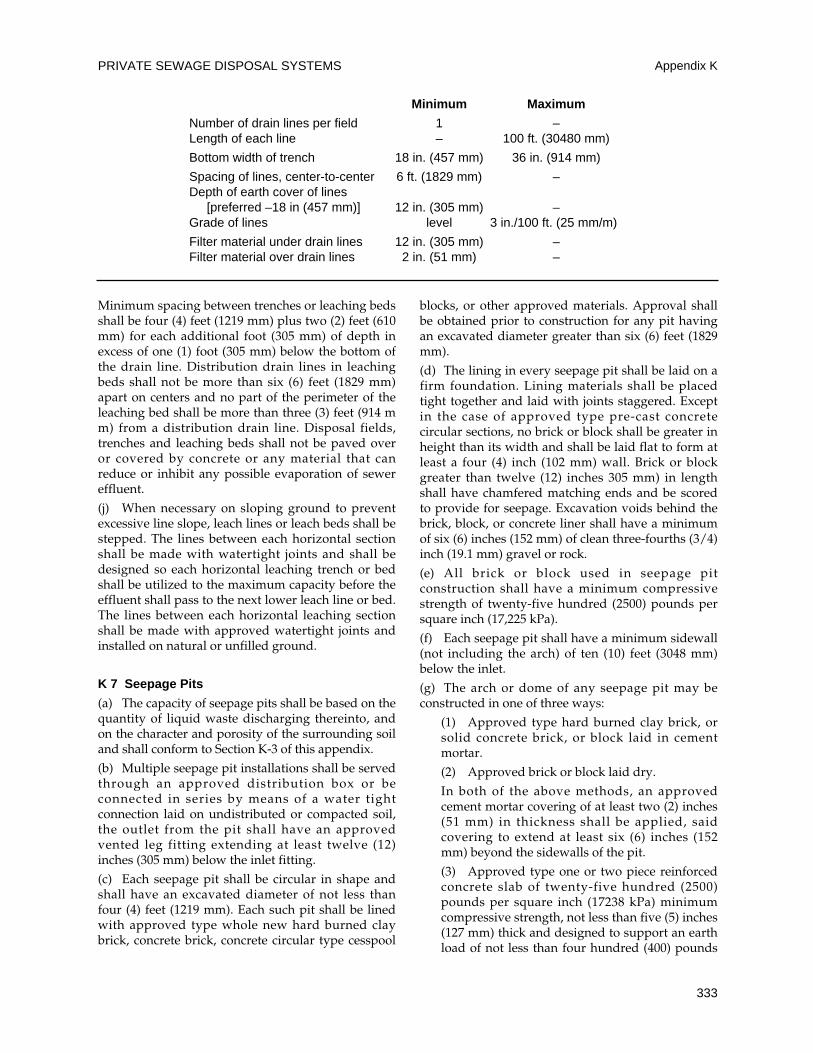
Minimum spacing between trenches or leaching bedsshall be four (4) feet (1219 mm) plus two (2) feet (610mm) for each additional foot (305 mm) of depth inexcess of one (1) foot (305 mm) below the bottom ofthe drain line. Distribution drain lines in leachingbeds shall not be more than six (6) feet (1829 mm)apart on centers and no part of the perimeter of theleaching bed shall be more than three (3) feet (914 mm) from a distribution drain line. Disposal fields,trenches and leaching beds shall not be paved overor covered by concrete or any material that canreduce or inhibit any possible evaporation of sewereffluent.
(j) When necessary on sloping ground to preventexcessive line slope, leach lines or leach beds shall bestepped. The lines between each horizontal sectionshall be made with watertight joints and shall bedesigned so each horizontal leaching trench or bedshall be utilized to the maximum capacity before theeffluent shall pass to the next lower leach line or bed.The lines between each horizontal leaching sectionshall be made with approved watertight joints andinstalled on natural or unfilled ground.
K 7 Seepage Pits
(a) The capacity of seepage pits shall be based on thequantity of liquid waste discharging thereinto, andon the character and porosity of the surrounding soiland shall conform to Section K-3 of this appendix.
(b) Multiple seepage pit installations shall be servedthrough an approved distribution box or beconnected in series by means of a water tightconnection laid on undistributed or compacted soil,the outlet from the pit shall have an approvedvented leg fitting extending at least twelve (12)inches (305 mm) below the inlet fitting.
(c) Each seepage pit shall be circular in shape andshall have an excavated diameter of not less thanfour (4) feet (1219 mm). Each such pit shall be linedwith approved type whole new hard burned claybrick, concrete brick, concrete circular type cesspool
blocks, or other approved materials. Approval shallbe obtained prior to construction for any pit havingan excavated diameter greater than six (6) feet (1829mm).
(d) The lining in every seepage pit shall be laid on afirm foundation. Lining materials shall be placedtight together and laid with joints staggered. Exceptin the case of approved type pre-cast concretecircular sections, no brick or block shall be greater inheight than its width and shall be laid flat to form atleast a four (4) inch (102 mm) wall. Brick or blockgreater than twelve (12) inches 305 mm) in lengthshall have chamfered matching ends and be scoredto provide for seepage. Excavation voids behind thebrick, block, or concrete liner shall have a minimumof six (6) inches (152 mm) of clean three-fourths (3/4)inch (19.1 mm) gravel or rock.
(e) All brick or block used in seepage pitconstruction shall have a minimum compressivestrength of twenty-five hundred (2500) pounds persquare inch (17,225 kPa).
(f) Each seepage pit shall have a minimum sidewall(not including the arch) of ten (10) feet (3048 mm)below the inlet.
(g) The arch or dome of any seepage pit may beconstructed in one of three ways:
(1) Approved type hard burned clay brick, orsolid concrete brick, or block laid in cementmortar.
(2) Approved brick or block laid dry.
In both of the above methods, an approvedcement mortar covering of at least two (2) inches(51 mm) in thickness shall be applied, saidcovering to extend at least six (6) inches (152mm) beyond the sidewalls of the pit.
(3) Approved type one or two piece reinforcedconcrete slab of twenty-five hundred (2500)pounds per square inch (17238 kPa) minimumcompressive strength, not less than five (5) inches(127 mm) thick and designed to support an earthload of not less than four hundred (400) pounds
PRIVATE SEWAGE DISPOSAL SYSTEMS Appendix K
333
Minimum Maximum
Number of drain lines per field 1 –Length of each line – 100 ft. (30480 mm)
Bottom width of trench 18 in. (457 mm) 36 in. (914 mm)
Spacing of lines, center-to-center 6 ft. (1829 mm) –Depth of earth cover of lines
[preferred –18 in (457 mm)] 12 in. (305 mm) –Grade of lines level 3 in./100 ft. (25 mm/m)
Filter material under drain lines 12 in. (305 mm) –Filter material over drain lines 2 in. (51 mm) –
per square foot (19.2 kPa). Each such cover shallbe provided with a nine (9) inch (229 mm)minimum inspection hole with plug or cover andshall be coated on the underside with anapproved bituminous or other nonpermeableprotective compound.
(h) The top of the arch or cover must be at leasteighteen (18) inches (457 mm) but not more than four(4) feet (1219 mm) below the surface of the ground.
(i) An approved vented inlet fitting shall beprovided in every seepage pit so arranged as toprevent the inflow from damaging the sidewall.
Exception: When using a one or two piececoncrete slab cover inlet, fitting may be a one-fourth (1/4) bend fitting discharging through anopening in the top of the slab cover. On multipleseepage pit installations, the outlet fittings shallbe per Section K 7(b) of this appendix.
K 8 Cesspools
(a) A cesspool shall be considered only as atemporary expedient pending the construction of apublic sewer, as an overflow facility when installedin conjunction with an existing cesspool, or as ameans of sewage disposal for limited, minor, ortemporary uses when first approved by theAdministrative Authority.
(b) Where it is established that a public sewersystem will be available in less than two (2) yearsand soil and ground water conditions are favorableto cesspool disposal, cesspools without septic tanksmay be installed for single family dwellings or forother limited uses when first approved by theAdministrative Authority.
(c) Each cesspool, when permitted, shall conform tothe construction requirements set forth in Section K 7of this appendix for seepage pits and shall have aminimum sidewall (not including arch) of twenty(20) feet (6096 mm) below the inlet provided,however, that when a strata of gravel or equallypervious material of four (4) feet (1219 mm) inthickness is found, the depth of such sidewall neednot be more than ten (10) feet (3048 mm) below theinlet.
(d) When overflow cesspools or seepage pits areadded to existing installations, the effluent shallleave the existing pit through an approved ventedleg extending at least twelve (12) inches (305 mm)downward into such existing pit and having itsoutlet flow line at least six (6) inches (152 mm) belowthe inlet. All pipe between pits shall be laid withapproved watertight joints.
K 9 Commercial or Industrial Special LiquidWaste Disposal
(a) When liquid wastes containing excessiveamounts of grease, garbage, flammable wastes, sand,or other ingredients which may affect the operationof a private sewage disposal system, an interceptorfor such wastes shall be installed.
(b) Installation of such interceptors shall complywith Section 1009.0 of the Uniform Plumbing Codeand their location shall be in accordance with TableK-1 of this appendix.
(c) Sampling box shall be installed when requiredby the Administrative Authority.
(d) Interceptors shall be of approved design and beof not less than two (2) compartments. Structuralrequirements shall be in compliance with theapplicable subparts of Section K 5 of this appendix.
(e) Interceptors shall be located as close to thesource as possible and be accessible for servicing. Allnecessary manholes for servicing shall be at gradelevel and be gastight.
(f) Waste discharge from interceptors may beconnected to a septic tank or other primary system orbe disposed into a separate disposal system.
(g) Recommended Design Criteria. (Formulaemay be adapted to other types of occupancies withsimilar wastes.) See charts on the following page.
K 10 Inspection and Testing
(a) Inspection
(1) Applicable provision of Section 103.5 of theUniform Plumbing Code and this appendix shallbe complied with. Plans may be required perSection 101.3 of this Code.
(2) System components shall be properlyidentified as to manufacturer. Septic tanks orother primary systems shall have the ratedcapacity permanently marked on the unit.
(3) Septic tanks or other primary systems shallbe installed on dry, level, well-compacted soil.
(4) If design is predicated on soil tests, thesystem shall be installed at the same locationand depth as the tested area.
(b) Testing
(1) Septic tanks or other primary componentsshall be filled with water to flow line prior torequesting inspection. All seams or joints shallbe left exposed (except the bottom) and the tankshall remain watertight.
(2) A flow test shall be performed through thesystem to the point of effluent disposal. All linesand components shall be watertight. Capacities,
UNIFORM PLUMBING CODE
334
Appendix K
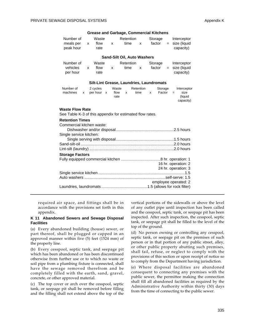
required air space, and fittings shall be inaccordance with the provisions set forth in thisappendix.
K 11 Abandoned Sewers and Sewage DisposalFacilities
(a) Every abandoned building (house) sewer, orpart thereof, shall be plugged or capped in anapproved manner within five (5) feet (1524 mm) ofthe property line.
(b) Every cesspool, septic tank, and seepage pitwhich has been abandoned or has been discontinuedotherwise from further use or to which no waste orsoil pipe from a plumbing fixture is connected, shallhave the sewage removed therefrom and becompletely filled with the earth, sand, gravel,concrete, or other approved material.
(c) The top cover or arch over the cesspool, septictank, or seepage pit shall be removed before fillingand the filling shall not extend above the top of the
vertical portions of the sidewalls or above the levelof any outlet pipe until inspection has been calledand the cesspool, septic tank, or seepage pit has beeninspected. After such inspection, the cesspool, septictank, or seepage pit shall be filled to the level of thetop of the ground.
(d) No person owning or controlling any cesspool,septic tank, or seepage pit on the premises of suchperson or in that portion of any public street, alley,or other public property abutting such premises,shall fail, refuse, or neglect to comply with theprovisions of this section or upon receipt of notice soto comply from the Department having jurisdiction.
(e) Where disposal facilities are abandonedconsequent to connecting any premises with thepublic sewer, the permittee making the connectionshall fill all abandoned facilities as required by theAdministrative Authority within thirty (30) daysfrom the time of connecting to the public sewer.
PRIVATE SEWAGE DISPOSAL SYSTEMS Appendix K
335
Grease and Garbage, Commercial KitchensNumber of Waste Retention Storage Interceptormeals per x flow x time x factor = size (liquidpeak hour rate capacity)
Sand-Silt Oil, Auto WashersNumber of Waste Retention Storage Interceptorvehicles x flow x time x factor = size (liquidper hour rate capacity)
Silt-Lint Grease, Laundries, LaundromatsNumber of 2 cycles Waste Retention Storage Interceptormachines x per hour x flow x time x Factor = size
rate (liquid capacity)
Waste Flow RateSee Table K-3 of this appendix for estimated flow rates.
Retention TimesCommercial kitchen waste:
Dishwasher and/or disposal.....................................................2.5 hoursSingle service kitchen:
Single serving with disposal.....................................................1.5 hoursSand-silt-oil .....................................................................................2.0 hoursLint-silt (laundry) .............................................................................2.0 hours
Storage FactorsFully equipped commercial kitchen ....................................8 hr. operation: 1
16 hr. operation: 224 hr. operation: 3
Single service kitchen ...............................................................................1.5Auto washers ..........................................................................self-serve: 1.5
employee operated: 2Laundries, laundromats ..........................................1.5 (allows for rock filter)
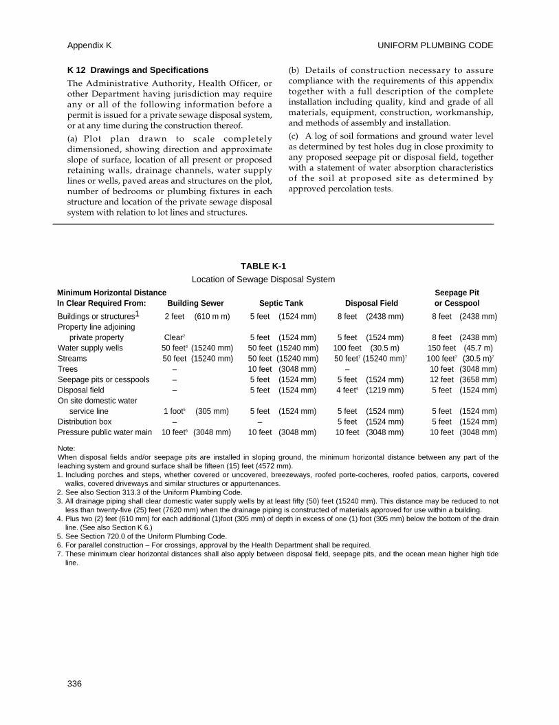
K 12 Drawings and Specifications
The Administrative Authority, Health Officer, orother Department having jurisdiction may requireany or all of the following information before apermit is issued for a private sewage disposal system,or at any time during the construction thereof.
(a) Plot plan drawn to scale completelydimensioned, showing direction and approximateslope of surface, location of all present or proposedretaining walls, drainage channels, water supplylines or wells, paved areas and structures on the plot,number of bedrooms or plumbing fixtures in eachstructure and location of the private sewage disposalsystem with relation to lot lines and structures.
(b) Details of construction necessary to assurecompliance with the requirements of this appendixtogether with a full description of the completeinstallation including quality, kind and grade of allmaterials, equipment, construction, workmanship,and methods of assembly and installation.
(c) A log of soil formations and ground water levelas determined by test holes dug in close proximity toany proposed seepage pit or disposal field, togetherwith a statement of water absorption characteristicsof the soil at proposed site as determined byapproved percolation tests.
UNIFORM PLUMBING CODE
336
Appendix K
TABLE K-1
Location of Sewage Disposal System
Minimum Horizontal Distance Seepage PitIn Clear Required From: Building Sewer Septic Tank Disposal Field or Cesspool
Buildings or structures1 2 feet (610 m m) 5 feet (1524 mm) 8 feet (2438 mm) 8 feet (2438 mm)Property line adjoining
private property Clear2 5 feet (1524 mm) 5 feet (1524 mm) 8 feet (2438 mm)Water supply wells 50 feet3 (15240 mm) 50 feet (15240 mm) 100 feet (30.5 m) 150 feet (45.7 m)Streams 50 feet (15240 mm) 50 feet (15240 mm) 50 feet7 (15240 mm)7 100 feet7 (30.5 m)7
Trees – 10 feet (3048 mm) – 10 feet (3048 mm)Seepage pits or cesspools – 5 feet (1524 mm) 5 feet (1524 mm) 12 feet (3658 mm)Disposal field – 5 feet (1524 mm) 4 feet4 (1219 mm) 5 feet (1524 mm)On site domestic water
service line 1 foot5 (305 mm) 5 feet (1524 mm) 5 feet (1524 mm) 5 feet (1524 mm)Distribution box – – 5 feet (1524 mm) 5 feet (1524 mm)Pressure public water main 10 feet6 (3048 mm) 10 feet (3048 mm) 10 feet (3048 mm) 10 feet (3048 mm)
Note: When disposal fields and/or seepage pits are installed in sloping ground, the minimum horizontal distance between any part of theleaching system and ground surface shall be fifteen (15) feet (4572 mm).1. Including porches and steps, whether covered or uncovered, breezeways, roofed porte-cocheres, roofed patios, carports, covered
walks, covered driveways and similar structures or appurtenances.2. See also Section 313.3 of the Uniform Plumbing Code.3. All drainage piping shall clear domestic water supply wells by at least fifty (50) feet (15240 mm). This distance may be reduced to not
less than twenty-five (25) feet (7620 mm) when the drainage piping is constructed of materials approved for use within a building.4. Plus two (2) feet (610 mm) for each additional (1)foot (305 mm) of depth in excess of one (1) foot (305 mm) below the bottom of the drain
line. (See also Section K 6.)5. See Section 720.0 of the Uniform Plumbing Code.6. For parallel construction – For crossings, approval by the Health Department shall be required.7. These minimum clear horizontal distances shall also apply between disposal field, seepage pits, and the ocean mean higher high tide
line.
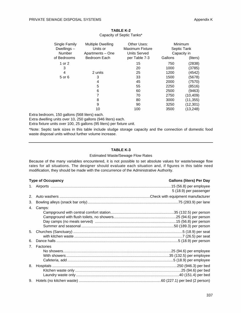
PRIVATE SEWAGE DISPOSAL SYSTEMS Appendix K
337
TABLE K-2Capacity of Septic Tanks*
Single Family Multiple Dwelling Other Uses: MinimumDwellings – Units or Maximum Fixture Septic Tank
Number Apartments – One Units Served Capacity inof Bedrooms Bedroom Each per Table 7-3 Gallons (liters)
1 or 2 15 750 (2838)3 20 1000 (3785)4 2 units 25 1200 (4542)
5 or 6 3 33 1500 (5678)4 45 2000 (7570)5 55 2250 (8516)6 60 2500 (9463)7 70 2750 (10,409)8 80 3000 (11,355)9 90 3250 (12,301)
10 100 3500 (13,248)
Extra bedroom, 150 gallons (568 liters) each.Extra dwelling units over 10, 250 gallons (946 liters) each.Extra fixture units over 100, 25 gallons (95 liters) per fixture unit.
*Note: Septic tank sizes in this table include sludge storage capacity and the connection of domestic foodwaste disposal units without further volume increase.
TABLE K-3
Estimated Waste/Sewage Flow Rates
Because of the many variables encountered, it is not possible to set absolute values for waste/sewage flowrates for all situations. The designer should evaluate each situation and, if figures in this table needmodification, they should be made with the concurrence of the Administrative Authority.
Type of Occupancy Gallons (liters) Per Day
1. Airports ....................................................................................................................15 (56.8) per employee5 (18.9) per passenger
2. Auto washers .......................................................................................Check with equipment manufacturer
3. Bowling alleys (snack bar only) .......................................................................................75 (283.9) per lane
4. Camps:Campground with central comfort station.............................................................35 (132.5) per personCampground with flush toilets, no showers............................................................25 (94.6) per personDay camps (no meals served) ..............................................................................15 (56.8) per personSummer and seasonal .........................................................................................50 (189.3) per person
5. Churches (Sanctuary) .........................................................................................................5 (18.9) per seatwith kitchen waste ........................................................................................................7 (26.5) per seat
6. Dance halls .....................................................................................................................5 (18.9) per person
7. FactoriesNo showers........................................................................................................25 (94.6) per employeeWith showers ...................................................................................................35 (132.5) per employeeCafeteria, add ......................................................................................................5 (18.9) per employee
8. Hospitals ........................................................................................................................250 (946.3) per bedKitchen waste only ......................................................................................................25 (94.6) per bedLaundry waste only ...................................................................................................40 (151.4) per bed
9. Hotels (no kitchen waste) ...............................................................................60 (227.1) per bed (2 person)
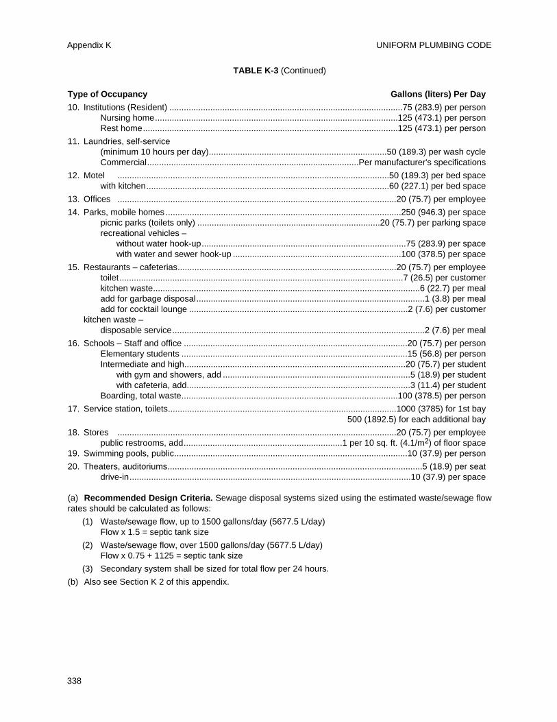
UNIFORM PLUMBING CODE
338
Appendix K
TABLE K-3 (Continued)
Type of Occupancy Gallons (liters) Per Day
10. Institutions (Resident) .................................................................................................75 (283.9) per personNursing home.....................................................................................................125 (473.1) per personRest home..........................................................................................................125 (473.1) per person
11. Laundries, self-service(minimum 10 hours per day)..........................................................................50 (189.3) per wash cycleCommercial........................................................................................Per manufacturer's specifications
12. Motel .................................................................................................................50 (189.3) per bed spacewith kitchen.....................................................................................................60 (227.1) per bed space
13. Offices ....................................................................................................................20 (75.7) per employee
14. Parks, mobile homes ..................................................................................................250 (946.3) per spacepicnic parks (toilets only) ............................................................................20 (75.7) per parking spacerecreational vehicles –
without water hook-up.....................................................................................75 (283.9) per spacewith water and sewer hook-up ......................................................................100 (378.5) per space
15. Restaurants – cafeterias...........................................................................................20 (75.7) per employeetoilet......................................................................................................................7 (26.5) per customerkitchen waste...............................................................................................................6 (22.7) per mealadd for garbage disposal...............................................................................................1 (3.8) per mealadd for cocktail lounge ...........................................................................................2 (7.6) per customer
kitchen waste –disposable service.........................................................................................................2 (7.6) per meal
16. Schools – Staff and office .............................................................................................20 (75.7) per personElementary students ..............................................................................................15 (56.8) per personIntermediate and high............................................................................................20 (75.7) per student
with gym and showers, add ..............................................................................5 (18.9) per studentwith cafeteria, add.............................................................................................3 (11.4) per student
Boarding, total waste..........................................................................................100 (378.5) per person
17. Service station, toilets...............................................................................................1000 (3785) for 1st bay500 (1892.5) for each additional bay
18. Stores ....................................................................................................................20 (75.7) per employeepublic restrooms, add..................................................................1 per 10 sq. ft. (4.1/m2) of floor space
19. Swimming pools, public.................................................................................................10 (37.9) per person
20. Theaters, auditoriums..........................................................................................................5 (18.9) per seatdrive-in.....................................................................................................................10 (37.9) per space
(a) Recommended Design Criteria. Sewage disposal systems sized using the estimated waste/sewage flowrates should be calculated as follows:
(1) Waste/sewage flow, up to 1500 gallons/day (5677.5 L/day)Flow x 1.5 = septic tank size
(2) Waste/sewage flow, over 1500 gallons/day (5677.5 L/day)Flow x 0.75 + 1125 = septic tank size
(3) Secondary system shall be sized for total flow per 24 hours.
(b) Also see Section K 2 of this appendix.
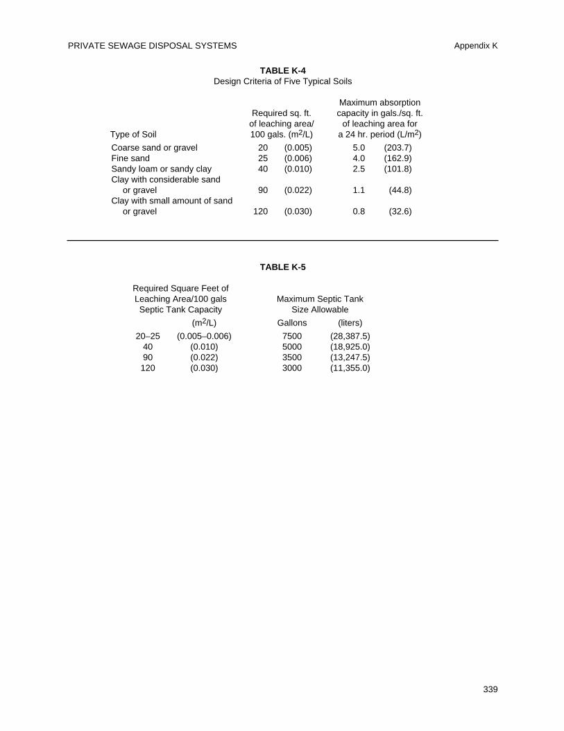
PRIVATE SEWAGE DISPOSAL SYSTEMS Appendix K
339
TABLE K-4Design Criteria of Five Typical Soils
Maximum absorptionRequired sq. ft. capacity in gals./sq. ft.
of leaching area/ of leaching area forType of Soil 100 gals. (m2/L) a 24 hr. period (L/m2)
Coarse sand or gravel 20 (0.005) 5.0 (203.7)Fine sand 25 (0.006) 4.0 (162.9)Sandy loam or sandy clay 40 (0.010) 2.5 (101.8)Clay with considerable sand
or gravel 90 (0.022) 1.1 (44.8)Clay with small amount of sand
or gravel 120 (0.030) 0.8 (32.6)
TABLE K-5
Required Square Feet ofLeaching Area/100 gals Maximum Septic TankSeptic Tank Capacity Size Allowable
(m2/L) Gallons (liters)
20–25 (0.005–0.006) 7500 (28,387.5)40 (0.010) 5000 (18,925.0)90 (0.022) 3500 (13,247.5)120 (0.030) 3000 (11,355.0)

UNIFORM PLUMBING CODE
340
L 1.0 Scope
L 1.1 The intent of this Appendix is to provideclarification of procedures for the design andapproval of engineered plumbing systems andalternate materials and equipment not specificallycovered in other parts of the Code.
L 1.2 The provisions of this Appendix apply tothe design, installation and inspection of anengineered plumbing systems and alternatematerials and equipment.
L 1.3 The Administrative Authority has theright to require descriptive details of an engineeredplumbing system, alternate material, or equipmentincluding pertinent technical data to be filed.
L 1.4 Components, materials and equipmentmust conform to standards and specifications listedin Table 14-1 of this Code and other nationalconsensus standards applicable to plumbing systemsand materials.
L 1.5 Where such standards and specificationsare not available, alternate materials and equipmentmust be approved per the provisions of Section 301.2of this Code.
L 2.0 Engineered Plumbing Systems
L 2.1 Definition. Engineered Plumbing System:A system designed for a specific building projectwith drawings and specifications indicatingplumbing materials to be installed, all as prepared bya person registered or licensed to perform plumbingdesign work.
L 2.2 Inspection and Installation. In other thanone- and two-family dwellings, the designer of thesystem is to provide periodic inspection of theinstallation on a schedule found suitable to theAdministrative Authority. Prior to the finalapproval, the designer must verify to theAdministrative Authority that the installation is incompliance with the approved plans, specificationsand data and such amendments thereto. Thedesigner must also certify to the AdministrativeAuthority that the installation is in compliance withthe applicable engineered design criteria.
L 2.3 Owner Information. The designer of thesystem must provide the Building Ownerinformation concerning the system, considerationsapplicable for any subsequent modifications to thesystem, and maintenance requirements as applicable.
L 3.0 Water Heat Exchangers
L 3.1 Heat exchangers used for heat transfer,heat recovery, or solar heating shall protect thepotable water system from being contaminated bythe heat transfer medium.
L 3.2 Single-wall heat exchangers shall bepermitted if they satisfy all of the followingrequirements:
1. The heat transfer medium is eitherpotable water or contains only substanceswhich are recognized as safe by the U.S.Food and Drug Administration.2. The pressure of the heat transfer mediumis maintained less than the normalminimum operating pressure of the potablewater system.
Exception: Steam complying withSection L 3.2 #1 above.
3. The equipment is permanently labeled toindicate that only additives recognized assafe by the FDA shall be used in the heattransfer medium.
L 3.3 Other heat exchanger designs may bepermitted where approved by the AdministrativeAuthority.
L 4.0 Fixture Unit Values for Bathroom Groups
L 4.1 Tables L-1 and L-2 reflect the fixture unitloads for the fixtures in bathrooms as groups, ratherthan as individual fixtures. Such fixtures includewater closets, lavatories and bathtubs or showers.The tables reflects diversity in the use of fixtureswithin a bathroom and between multiple bathrooms.
L 4.2 The listed water supply fixture unit valuesin Table L-1 reflect the load of entire bathroomgroups on the cold water service. Individual hot andcold water branch piping to the fixtures should besized according to Chapter 6 and Appendix A.
L 4.3 The listed drainage fixture unit values inTable L-2 reflect the load of entire bathroom groupson the sanitary drainage system. Where fixtureswithin bathrooms connect to different branches of thedrainage system, the fixture unit values for theindividual fixtures shall be used, as listed in Table 7-3.
L 5.0 Vacuum Drainage Systems
L 5.1 Vacuum drainage systems shall beconsidered engineered systems and shall complywith the requirements of L 1.0 and L 2.0.
341
APPENDIX LALTERNATE PLUMBING SYSTEMS
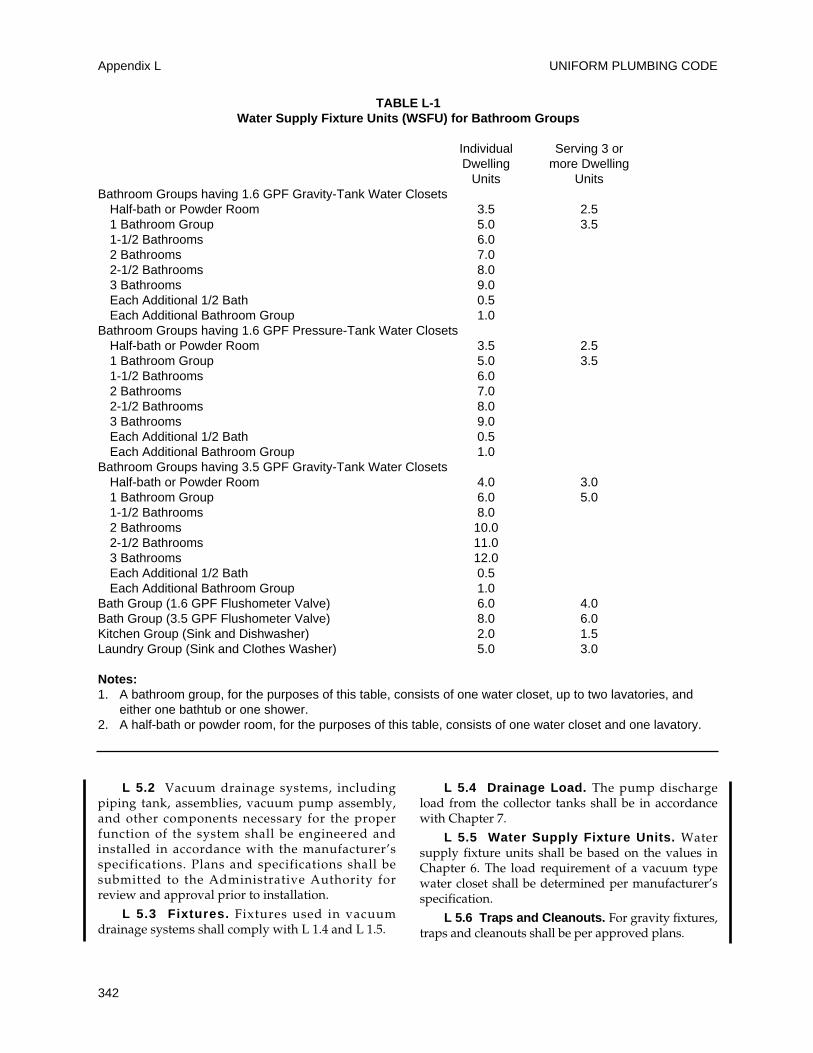
L 5.2 Vacuum drainage systems, includingpiping tank, assemblies, vacuum pump assembly,and other components necessary for the properfunction of the system shall be engineered andinstalled in accordance with the manufacturer’sspecifications. Plans and specifications shall besubmitted to the Administrative Authority forreview and approval prior to installation.
L 5.3 Fixtures. Fixtures used in vacuumdrainage systems shall comply with L 1.4 and L 1.5.
L 5.4 Drainage Load. The pump dischargeload from the collector tanks shall be in accordancewith Chapter 7.
L 5.5 Water Supply Fixture Units. Watersupply fixture units shall be based on the values inChapter 6. The load requirement of a vacuum typewater closet shall be determined per manufacturer’sspecification.
L 5.6 Traps and Cleanouts. For gravity fixtures,traps and cleanouts shall be per approved plans.
UNIFORM PLUMBING CODE
342
Appendix L
TABLE L-1Water Supply Fixture Units (WSFU) for Bathroom Groups
Individual Serving 3 orDwelling more Dwelling
Units UnitsBathroom Groups having 1.6 GPF Gravity-Tank Water Closets
Half-bath or Powder Room 3.5 2.51 Bathroom Group 5.0 3.51-1/2 Bathrooms 6.02 Bathrooms 7.02-1/2 Bathrooms 8.03 Bathrooms 9.0Each Additional 1/2 Bath 0.5Each Additional Bathroom Group 1.0
Bathroom Groups having 1.6 GPF Pressure-Tank Water ClosetsHalf-bath or Powder Room 3.5 2.51 Bathroom Group 5.0 3.51-1/2 Bathrooms 6.02 Bathrooms 7.02-1/2 Bathrooms 8.03 Bathrooms 9.0Each Additional 1/2 Bath 0.5Each Additional Bathroom Group 1.0
Bathroom Groups having 3.5 GPF Gravity-Tank Water ClosetsHalf-bath or Powder Room 4.0 3.01 Bathroom Group 6.0 5.01-1/2 Bathrooms 8.02 Bathrooms 10.02-1/2 Bathrooms 11.03 Bathrooms 12.0Each Additional 1/2 Bath 0.5Each Additional Bathroom Group 1.0
Bath Group (1.6 GPF Flushometer Valve) 6.0 4.0Bath Group (3.5 GPF Flushometer Valve) 8.0 6.0Kitchen Group (Sink and Dishwasher) 2.0 1.5Laundry Group (Sink and Clothes Washer) 5.0 3.0
Notes:1. A bathroom group, for the purposes of this table, consists of one water closet, up to two lavatories, and
either one bathtub or one shower.2. A half-bath or powder room, for the purposes of this table, consists of one water closet and one lavatory.
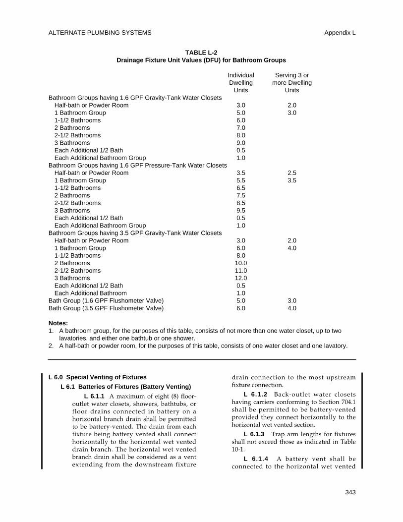
L 6.0 Special Venting of Fixtures
L 6.1 Batteries of Fixtures (Battery Venting)
L 6.1.1 A maximum of eight (8) floor-outlet water closets, showers, bathtubs, orfloor drains connected in battery on ahorizontal branch drain shall be permittedto be battery-vented. The drain from eachfixture being battery vented shall connecthorizontally to the horizontal wet venteddrain branch. The horizontal wet ventedbranch drain shall be considered as a ventextending from the downstream fixture
drain connection to the most upstreamfixture connection.
L 6.1.2 Back-outlet water closetshaving carriers conforming to Section 704.1shall be permitted to be battery-ventedprovided they connect horizontally to thehorizontal wet vented section.
L 6.1.3 Trap arm lengths for fixturesshall not exceed those as indicated in Table10-1.
L 6.1.4 A battery vent shall beconnected to the horizontal wet vented
ALTERNATE PLUMBING SYSTEMS Appendix L
343
TABLE L-2Drainage Fixture Unit Values (DFU) for Bathroom Groups
Individual Serving 3 orDwelling more Dwelling
Units UnitsBathroom Groups having 1.6 GPF Gravity-Tank Water Closets
Half-bath or Powder Room 3.0 2.01 Bathroom Group 5.0 3.01-1/2 Bathrooms 6.02 Bathrooms 7.02-1/2 Bathrooms 8.03 Bathrooms 9.0Each Additional 1/2 Bath 0.5Each Additional Bathroom Group 1.0
Bathroom Groups having 1.6 GPF Pressure-Tank Water ClosetsHalf-bath or Powder Room 3.5 2.51 Bathroom Group 5.5 3.51-1/2 Bathrooms 6.52 Bathrooms 7.52-1/2 Bathrooms 8.53 Bathrooms 9.5Each Additional 1/2 Bath 0.5Each Additional Bathroom Group 1.0
Bathroom Groups having 3.5 GPF Gravity-Tank Water ClosetsHalf-bath or Powder Room 3.0 2.01 Bathroom Group 6.0 4.01-1/2 Bathrooms 8.02 Bathrooms 10.02-1/2 Bathrooms 11.03 Bathrooms 12.0Each Additional 1/2 Bath 0.5Each Additional Bathroom 1.0
Bath Group (1.6 GPF Flushometer Valve) 5.0 3.0Bath Group (3.5 GPF Flushometer Valve) 6.0 4.0
Notes:1. A bathroom group, for the purposes of this table, consists of not more than one water closet, up to two
lavatories, and either one bathtub or one shower.2. A half-bath or powder room, for the purposes of this table, consists of one water closet and one lavatory.
branch drain between the two (2) mostupstream fixture drains.
L 6.1.5 The entire length of the wet-vented section of the horizontal branchdrain shall be uniformly sized for the totaldrainage discharge connected thereto as perTable 7-5. The maximum slope of thehorizontal drain shall be three-eighths (3/8)inch (10 mm) per foot (300 mm).
L 6.1.6 A relief vent shall be providedon each wet-vented horizontal drain branchbelow the upper-most floor. The relief ventshall connect to the horizontal drain branchbetween the stack and the first upstreamfixture drain.
L 6.1.7 Battery vents and relief ventconnections shall be taken off verticallyfrom the top of the horizontal drain.
Battery vents and relief vents shall notbe used as a vertical wet vent(s).
L 6.1.8 Lavatories and drinkingfountains shall be permitted to connecthorizontally to the horizontal wet-ventedbranch drain provided that they are locatedon the same floor as the battery-ventedfixtures and each is provided with either anindividual or common vent.
L 6.1.9 Batteries of more than eight (8)battery vented fixtures shall have a separatebattery vent for each group of eight (8) orless fixtures, and the horizontal branchdrain in each group shall be sized for thetotal drainage into the branch, including allupstream branches and the fixtures withinthe particular group.
L 6.1.10 All battery vents and reliefvents shall be sized according to Section904.0, but shall be not less than one-half(1/2) the area of the drain pipe that theyserve and shall comply with Section 905.0
L 6.2 Single Bathroom or Single Toilet Room
L 6.2.1 An individually-vented lavatory ina single bathroom or single toilet room shall bepermitted to serve as the wet vent for one (1)water closet and/or one (1) bathtub or showerstall, or one (1) water closet and/or one (1)bathtub/shower combination if all of thefollowing conditions are met:
(1) The wet vent, and the dry vent extendingfrom the wet vent, shall be two (2) inch (50mm) minimum pipe size.
(2) The wet vent pipe opening shall not bebelow the weir of the trap that it serves.
Vent sizing, grades, and connections shallcomply with Sections 904.0 and 905.0.
(3) The horizontal branch drain serving boththe lavatory and the bathtub or shower stallshall be two (2) inch (50 mm) minimum pipesize.
(4) The length of the trap arm from thebathtub or shower stall complies with thelimits in Table 10-1.
(5) The distance from the outlet of the watercloset to the connection of the wet ventcomplies with the limits in Table 10-1.
(6) The horizontal branch drain serving thelavatory and the bathtub or shower stallshall connect to the horizontal water closetbranch above its centerline. When thebathroom or toilet room is the top-most loadon a stack, the horizontal branch serving thelavatory and the bathtub or shower stallshall be permitted to connect to the stackbelow the water closet branch.
(7) No fixture other than those listed in L 6.2.1 shall discharge through a singlebathroom or single toilet room wet ventedsystem.
L 6.3 Double Bathtubs, Bathtub/ShowerCombinations, Shower Stalls and Lavatories
Two (2) lavatories, each rated at 1.0 drainage fixtureunit (DFU), and two (2) bathtubs, bathtub/showercombinations or shower stalls, installed in adjacentbathrooms, shall be permitted to drain to ahorizontal drain branch that is two (2) inches (50 mm) minimum pipe size, with a common ventfor the lavatories and no individual vents for thebathtubs, bathtub/shower combinations or showerstalls, provided that the wet vent from the lavatoriesand their dry vent is two (2) inches (50 mm)minimum pipe size and the length of all trap armscomply with the limits in Table 10-1.
UNIFORM PLUMBING CODE
344
Appendix L
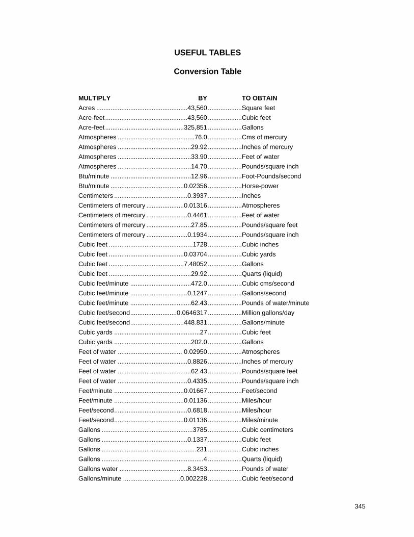
MULTIPLY BY TO OBTAIN
Acres ...................................................43,560...................Square feet
Acre-feet ..............................................43,560...................Cubic feet
Acre-feet ............................................325,851...................Gallons
Atmospheres ...........................................76.0 ...................Cms of mercury
Atmospheres .........................................29.92 ...................Inches of mercury
Atmospheres .........................................33.90 ...................Feet of water
Atmospheres .........................................14.70 ...................Pounds/square inch
Btu/minute .............................................12.96 ...................Foot-Pounds/second
Btu/minute .........................................0.02356...................Horse-power
Centimeters .........................................0.3937...................Inches
Centimeters of mercury .....................0.01316...................Atmospheres
Centimeters of mercury .......................0.4461...................Feet of water
Centimeters of mercury .........................27.85 ...................Pounds/square feet
Centimeters of mercury .......................0.1934...................Pounds/square inch
Cubic feet ...............................................1728...................Cubic inches
Cubic feet ..........................................0.03704...................Cubic yards
Cubic feet ..........................................7.48052...................Gallons
Cubic feet ..............................................29.92 ...................Quarts (liquid)
Cubic feet/minute ..................................472.0 ...................Cubic cms/second
Cubic feet/minute ................................0.1247...................Gallons/second
Cubic feet/minute ..................................62.43 ...................Pounds of water/minute
Cubic feet/second..........................0.0646317...................Million gallons/day
Cubic feet/second..............................448.831...................Gallons/minute
Cubic yards ................................................27 ...................Cubic feet
Cubic yards ...........................................202.0 ...................Gallons
Feet of water .................................... 0.02950...................Atmospheres
Feet of water .......................................0.8826...................Inches of mercury
Feet of water .........................................62.43 ...................Pounds/square feet
Feet of water .......................................0.4335...................Pounds/square inch
Feet/minute .......................................0.01667...................Feet/second
Feet/minute .......................................0.01136...................Miles/hour
Feet/second.........................................0.6818...................Miles/hour
Feet/second.......................................0.01136...................Miles/minute
Gallons ...................................................3785...................Cubic centimeters
Gallons ................................................0.1337...................Cubic feet
Gallons .....................................................231...................Cubic inches
Gallons .........................................................4 ...................Quarts (liquid)
Gallons water ......................................8.3453...................Pounds of water
Gallons/minute ................................0.002228...................Cubic feet/second
345
USEFUL TABLES
Conversion Table
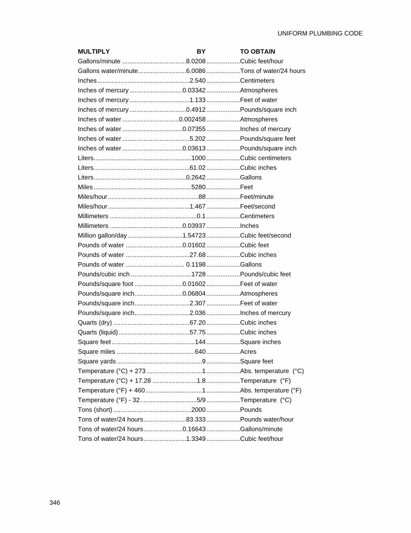
MULTIPLY BY TO OBTAIN
Gallons/minute ....................................8.0208...................Cubic feet/hour
Gallons water/minute...........................6.0086...................Tons of water/24 hours
Inches....................................................2.540...................Centimeters
Inches of mercury..............................0.03342...................Atmospheres
Inches of mercury..................................1.133...................Feet of water
Inches of mercury................................0.4912...................Pounds/square inch
Inches of water ................................0.002458...................Atmospheres
Inches of water ..................................0.07355...................Inches of mercury
Inches of water ......................................5.202...................Pounds/square feet
Inches of water ..................................0.03613...................Pounds/square inch
Liters.......................................................1000...................Cubic centimeters
Liters......................................................61.02 ...................Cubic inches
Liters....................................................0.2642...................Gallons
Miles .......................................................5280...................Feet
Miles/hour ...................................................88 ...................Feet/minute
Miles/hour ..............................................1.467...................Feet/second
Millimeters .................................................0.1 ...................Centimeters
Millimeters .........................................0.03937...................Inches
Million gallon/day...............................1.54723...................Cubic feet/second
Pounds of water ................................0.01602...................Cubic feet
Pounds of water ....................................27.68 ...................Cubic inches
Pounds of water ................................. 0.1198...................Gallons
Pounds/cubic inch ..................................1728...................Pounds/cubic feet
Pounds/square foot ...........................0.01602...................Feet of water
Pounds/square inch...........................0.06804...................Atmospheres
Pounds/square inch...............................2.307...................Feet of water
Pounds/square inch...............................2.036...................Inches of mercury
Quarts (dry) ...........................................67.20 ...................Cubic inches
Quarts (liquid) ........................................57.75 ...................Cubic inches
Square feet ...............................................144...................Square inches
Square miles ............................................640...................Acres
Square yards ................................................9 ...................Square feet
Temperature (°C) + 273 ...............................1 ...................Abs. temperature (°C)
Temperature (°C) + 17.28 .........................1.8 ...................Temperature (°F)
Temperature (°F) + 460................................1 ...................Abs. temperature (°F)
Temperature (°F) - 32................................5/9 ...................Temperature (°C)
Tons (short) ............................................2000...................Pounds
Tons of water/24 hours........................83.333...................Pounds water/hour
Tons of water/24 hours......................0.16643...................Gallons/minute
Tons of water/24 hours........................1.3349...................Cubic feet/hour
UNIFORM PLUMBING CODE
346
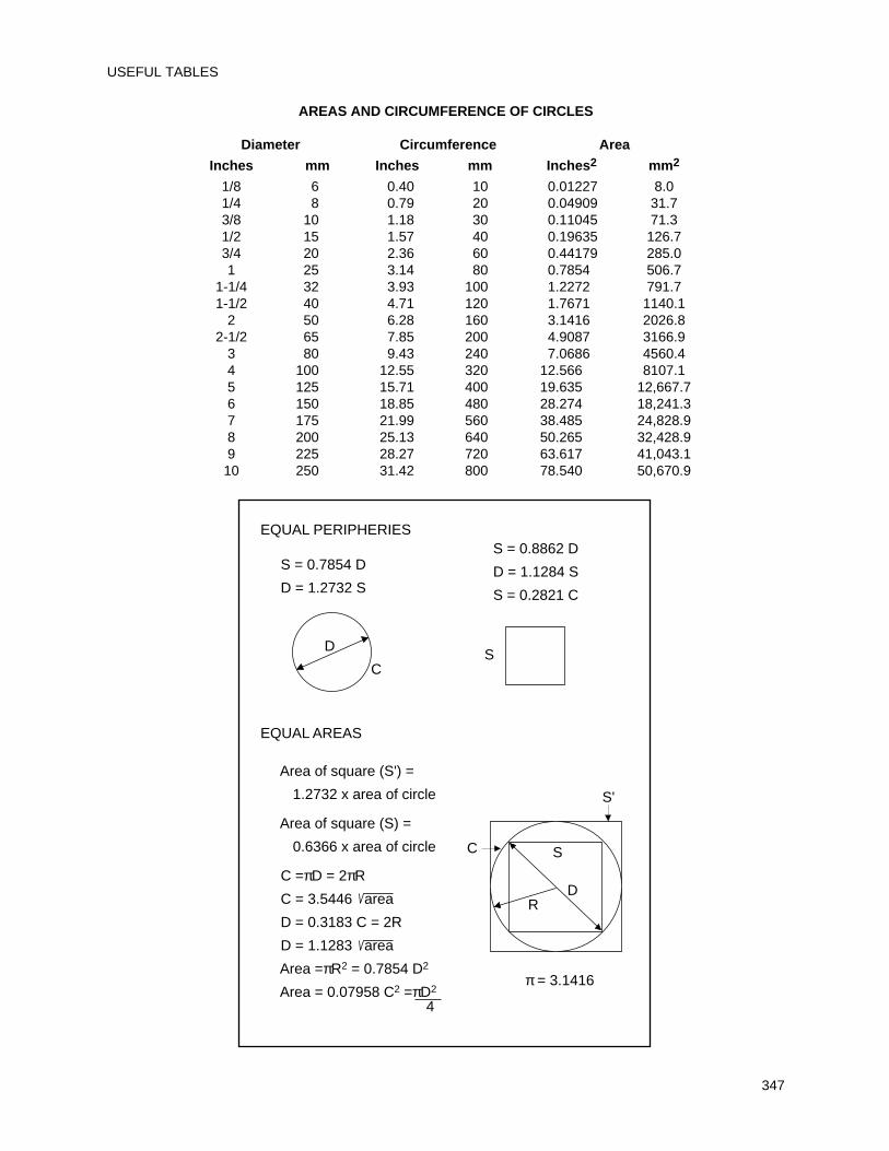
AREAS AND CIRCUMFERENCE OF CIRCLES
Diameter Circumference Area
Inches mm Inches mm Inches2 mm2
1/8 6 0.40 10 0.01227 8.01/4 8 0.79 20 0.04909 31.73/8 10 1.18 30 0.11045 71.31/2 15 1.57 40 0.19635 126.73/4 20 2.36 60 0.44179 285.01 25 3.14 80 0.7854 506.7
1-1/4 32 3.93 100 1.2272 791.71-1/2 40 4.71 120 1.7671 1140.1
2 50 6.28 160 3.1416 2026.82-1/2 65 7.85 200 4.9087 3166.9
3 80 9.43 240 7.0686 4560.44 100 12.55 320 12.566 8107.15 125 15.71 400 19.635 12,667.76 150 18.85 480 28.274 18,241.37 175 21.99 560 38.485 24,828.98 200 25.13 640 50.265 32,428.99 225 28.27 720 63.617 41,043.110 250 31.42 800 78.540 50,670.9
CS
EQUAL PERIPHERIES
S = 0.7854 D
D = 1.2732 S
S = 0.8862 D
D = 1.1284 S
S = 0.2821 C
EQUAL AREAS
Area of square (S') =
1.2732 x area of circle
Area of square (S) =
0.6366 x area of circle
C =πD = 2πR
C = 3.5446 area
D = 0.3183 C = 2R
D = 1.1283 area
Area =πR2 = 0.7854 D2
Area = 0.07958 C2 =πD2
4
D
π = 3.1416
S'
C S
DR
USEFUL TABLES
347
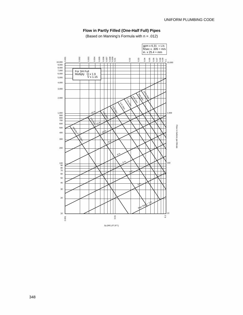
UNIFORM PLUMBING CODE
348
Flow in Partly Filled (One-Half Full) Pipes(Based on Manning’s Formula with n = .012)
0.00
1
0.00
2
0.00
3
0.00
4
0.00
5
0.00
6
0.00
7
0.00
80.
009
0.01
0.02
0.03
0.04
0.05
0.06
0.07
0.08
0.09
0.1
10,0009,000
8,0007,000
6,000
5,000
4,000
3,000
2,000
1,000900800700
600
500
400
300
200
100
50
908070
60
40
30
20
10
15 in.
12 in.
10 in.
8 in.
6 in.
5 in.
4 in.
3 in.
Pipe Size = 2 in.
Velocity = 2 Ft./Sec.
3 Ft./Sec.
4 Ft./Sec.
5 Ft./Sec.
6 Ft./Sec.7 Ft./Sec.
8 Ft./Sec.9 Ft./Sec.
10 Ft./Sec.
SLOPE (FT./FT.)
Flow
in Gallons per M
inute
1,000
100
10,000
10
0.1
0.01
0.00
1
For 3/4 FullMultiply Q x 1.9 V x 1.15
gpm x 6.31 = L/sft/sec x .305 = m/sin. x 25.4 = mm
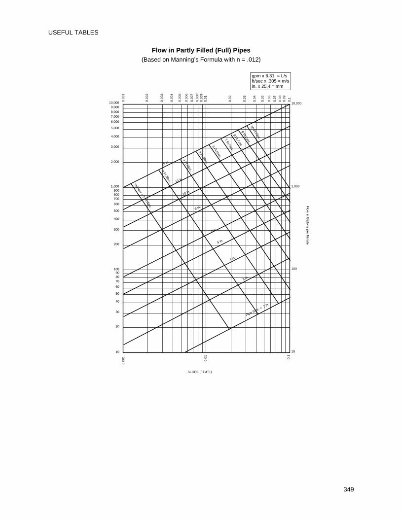
Flow in Partly Filled (Full) Pipes(Based on Manning’s Formula with n = .012)
USEFUL TABLES
349
0.00
1
0.00
2
0.00
3
0.00
4
0.00
5
0.00
6
0.00
7
0.00
80.
009
0.01
0.02
0.03
0.04
0.05
0.06
0.07
0.08
0.09
0.1
10,0009,000
8,0007,000
6,000
5,000
4,000
3,000
2,000
1,000900800700
600
500
400
300
200
100
50
908070
60
40
30
20
10
15 in.
12 in.
10 in.
8 in.
6 in.
5 in.
4 in.
3 in.
Pipe Size = 2 in.
Velocity = 2 Ft./Sec.
3 Ft./Sec.
4 Ft./Sec.
5 Ft./Sec.
6 Ft./Sec.
7 Ft./Sec.8 Ft./Sec.
9 Ft./Sec.10 Ft./Sec.
SLOPE (FT./FT.)
Flow
in Gallons per M
inute
1,000
100
10,000
10
0.1
0.01
0.00
1
gpm x 6.31 = L/sft/sec x .305 = m/sin. x 25.4 = mm
METRIC SYSTEM
(INTERNATIONAL SYSTEM OF UNITS – SI)
For the users of this Code, we are including a short explanation and some conversion tables to aid in theconversion of our familiar English units to the forthcoming SI units.
This is written with the Code users in mind, and will detail only those measurements used in everyday workand calculations. For the scientific units, we recommend the use of ANSI Z210.1, "Metric Practice Guide."
GENERAL COMMENTS
Our present system of measuring involves the three dimensions of force, length and time. The SI units involvemass, length and time. The change of force to mass has meaning in scientific and engineering work, but forpractical use in ordinary construction, we will show kilogram to pounds conversion values, although an exactconversion would be pounds force divided by the acceleration due to gravity to mass units.
In the same manner, the SI units for temperature expressed in Kelvins and based on absolute zero will begiven as degrees Celsius, which is the more familiar and practical Centigrade degrees.
The SI system measures angles in radians where there are 2 pi radians in a circle, but using a 1.5708 bendto change from a vertical stack to a horizontal house drain is not as easy as calling out a 1/4 bend or an ell forwater piping.
The foregoing notes are intended to show that in making conversions from one unit system to another, a littlecommon sense must be used and the degree of accuracy needed to do the job at hand.
The following tables are set up using this approach and using the preferred SI units.
UNIFORM PLUMBING CODE
350
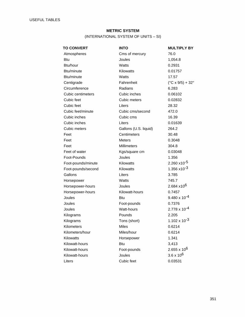
METRIC SYSTEM(INTERNATIONAL SYSTEM OF UNITS – SI)
TO CONVERT INTO MULTIPLY BY
Atmospheres Cms of mercury 76.0
Btu Joules 1,054.8
Btu/hour Watts 0.2931
Btu/minute Kilowatts 0.01757
Btu/minute Watts 17.57
Centigrade Fahrenheit (°C x 9/5) + 32°
Circumference Radians 6.283
Cubic centimeters Cubic inches 0.06102
Cubic feet Cubic meters 0.02832
Cubic feet Liters 28.32
Cubic feet/minute Cubic cms/second 472.0
Cubic inches Cubic cms 16.39
Cubic inches Liters 0.01639
Cubic meters Gallons (U.S. liquid) 264.2
Feet Centimeters 30.48
Feet Meters 0.3048
Feet Millimeters 304.8
Feet of water Kgs/square cm 0.03048
Foot-Pounds Joules 1.356
Foot-pounds/minute Kilowatts 2.260 x10⁻⁵
Foot-pounds/second Kilowatts 1.356 x10⁻³
Gallons Liters 3.785
Horsepower Watts 745.7
Horsepower-hours Joules 2.684 x10⁶
Horsepower-hours Kilowatt-hours 0.7457
Joules Btu 9.480 x 10⁻⁴
Joules Foot-pounds 0.7376
Joules Watt-hours 2.778 x 10⁻⁴
Kilograms Pounds 2.205
Kilograms Tons (short) 1.102 x 10⁻³
Kilometers Miles 0.6214
Kilometers/hour Miles/hour 0.6214
Kilowatts Horsepower 1.341
Kilowatt-hours Btu 3,413
Kilowatt-hours Foot-pounds 2.655 x 10⁶
Kilowatt-hours Joules 3.6 x 10⁶
Liters Cubic feet 0.03531
USEFUL TABLES
351
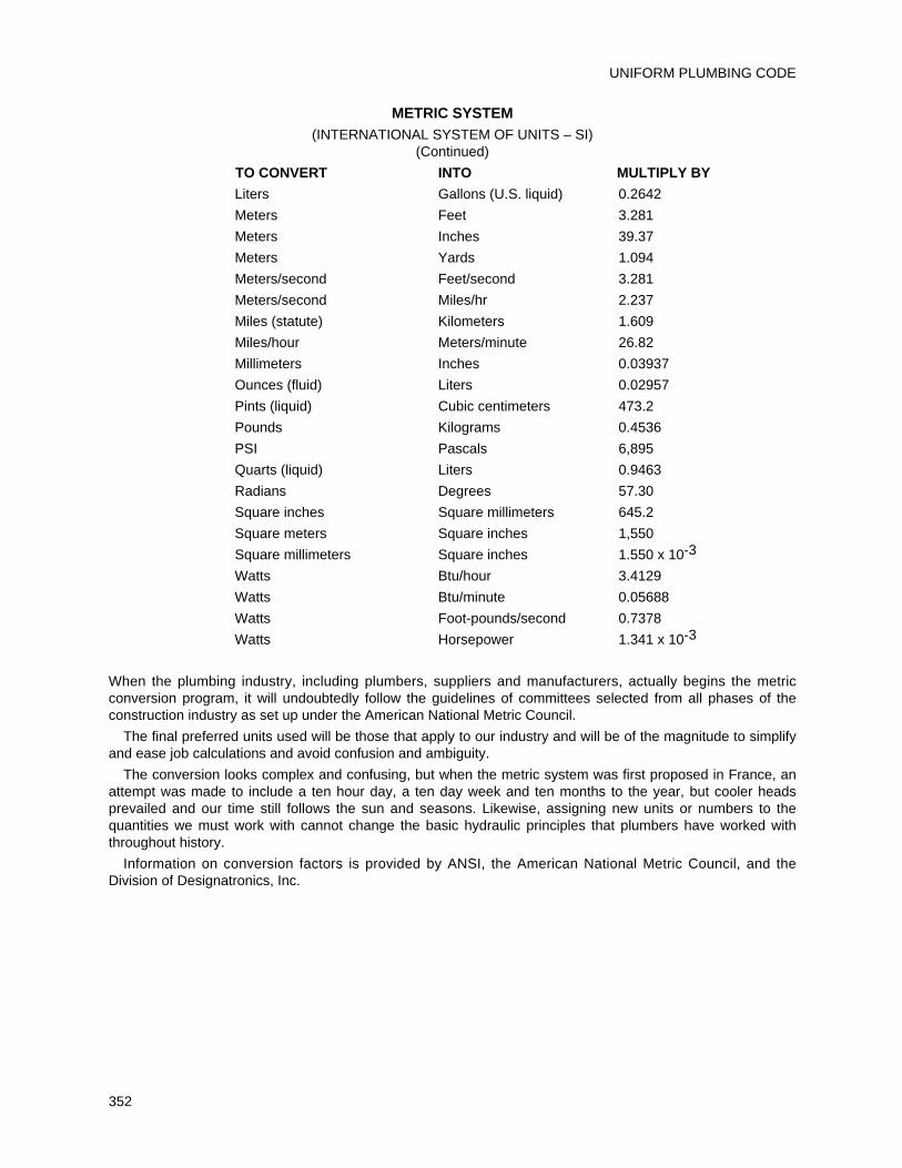
METRIC SYSTEM(INTERNATIONAL SYSTEM OF UNITS – SI)
(Continued)
TO CONVERT INTO MULTIPLY BY
Liters Gallons (U.S. liquid) 0.2642
Meters Feet 3.281
Meters Inches 39.37
Meters Yards 1.094
Meters/second Feet/second 3.281
Meters/second Miles/hr 2.237
Miles (statute) Kilometers 1.609
Miles/hour Meters/minute 26.82
Millimeters Inches 0.03937
Ounces (fluid) Liters 0.02957
Pints (liquid) Cubic centimeters 473.2
Pounds Kilograms 0.4536
PSI Pascals 6,895
Quarts (liquid) Liters 0.9463
Radians Degrees 57.30
Square inches Square millimeters 645.2
Square meters Square inches 1,550
Square millimeters Square inches 1.550 x 10⁻³
Watts Btu/hour 3.4129
Watts Btu/minute 0.05688
Watts Foot-pounds/second 0.7378
Watts Horsepower 1.341 x 10⁻³
When the plumbing industry, including plumbers, suppliers and manufacturers, actually begins the metricconversion program, it will undoubtedly follow the guidelines of committees selected from all phases of theconstruction industry as set up under the American National Metric Council.
The final preferred units used will be those that apply to our industry and will be of the magnitude to simplifyand ease job calculations and avoid confusion and ambiguity.
The conversion looks complex and confusing, but when the metric system was first proposed in France, anattempt was made to include a ten hour day, a ten day week and ten months to the year, but cooler headsprevailed and our time still follows the sun and seasons. Likewise, assigning new units or numbers to thequantities we must work with cannot change the basic hydraulic principles that plumbers have worked withthroughout history.
Information on conversion factors is provided by ANSI, the American National Metric Council, and theDivision of Designatronics, Inc.
UNIFORM PLUMBING CODE
352
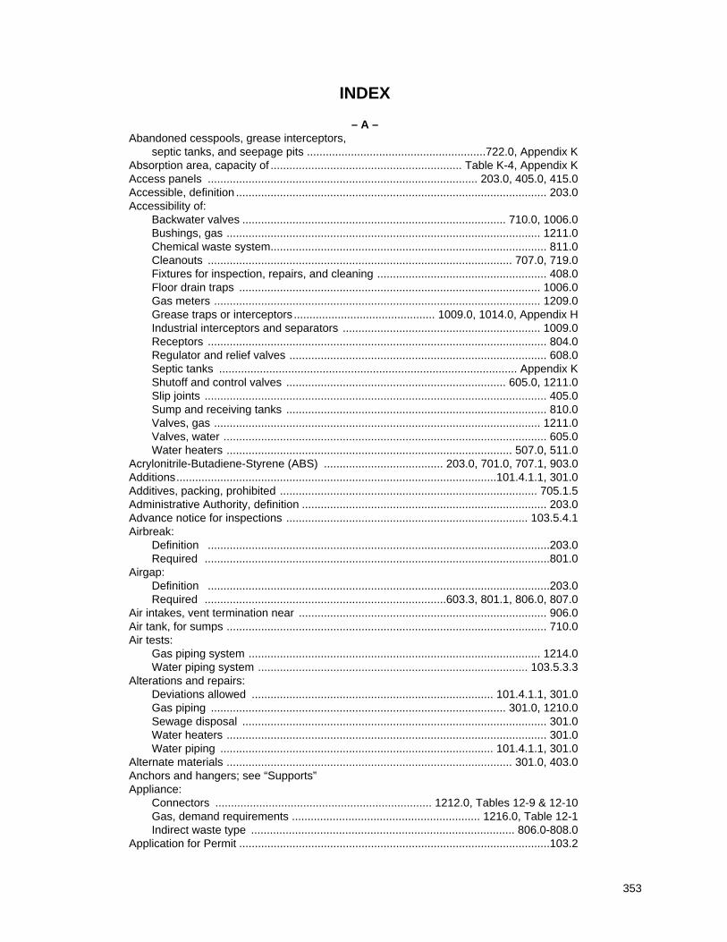
INDEX
– A –Abandoned cesspools, grease interceptors,
septic tanks, and seepage pits .........................................................722.0, Appendix KAbsorption area, capacity of ............................................................. Table K-4, Appendix KAccess panels ...................................................................................... 203.0, 405.0, 415.0Accessible, definition ................................................................................................... 203.0Accessibility of:
Backwater valves .................................................................................... 710.0, 1006.0Bushings, gas .................................................................................................... 1211.0Chemical waste system........................................................................................ 811.0Cleanouts ................................................................................................. 707.0, 719.0Fixtures for inspection, repairs, and cleaning ...................................................... 408.0Floor drain traps ................................................................................................ 1006.0Gas meters ........................................................................................................ 1209.0Grease traps or interceptors ............................................. 1009.0, 1014.0, Appendix HIndustrial interceptors and separators ............................................................... 1009.0Receptors ............................................................................................................ 804.0Regulator and relief valves .................................................................................. 608.0Septic tanks ............................................................................................... Appendix KShutoff and control valves ...................................................................... 605.0, 1211.0Slip joints ............................................................................................................. 405.0Sump and receiving tanks ................................................................................... 810.0Valves, gas ........................................................................................................ 1211.0Valves, water ....................................................................................................... 605.0Water heaters ........................................................................................... 507.0, 511.0
Acrylonitrile-Butadiene-Styrene (ABS) ...................................... 203.0, 701.0, 707.1, 903.0Additions......................................................................................................101.4.1.1, 301.0Additives, packing, prohibited .................................................................................. 705.1.5Administrative Authority, definition .............................................................................. 203.0Advance notice for inspections ............................................................................. 103.5.4.1Airbreak:
Definition .............................................................................................................203.0Required ..............................................................................................................801.0
Airgap:Definition .............................................................................................................203.0Required .............................................................................603.3, 801.1, 806.0, 807.0
Air intakes, vent termination near ............................................................................... 906.0Air tank, for sumps ...................................................................................................... 710.0Air tests:
Gas piping system ............................................................................................. 1214.0Water piping system ...................................................................................... 103.5.3.3
Alterations and repairs:Deviations allowed ............................................................................. 101.4.1.1, 301.0Gas piping .............................................................................................. 301.0, 1210.0Sewage disposal ................................................................................................. 301.0Water heaters ...................................................................................................... 301.0Water piping ....................................................................................... 101.4.1.1, 301.0
Alternate materials ........................................................................................... 301.0, 403.0Anchors and hangers; see “Supports”Appliance:
Connectors ..................................................................... 1212.0, Tables 12-9 & 12-10Gas, demand requirements ............................................................ 1216.0, Table 12-1Indirect waste type .................................................................................... 806.0-808.0
Application for Permit ...................................................................................................103.2
353
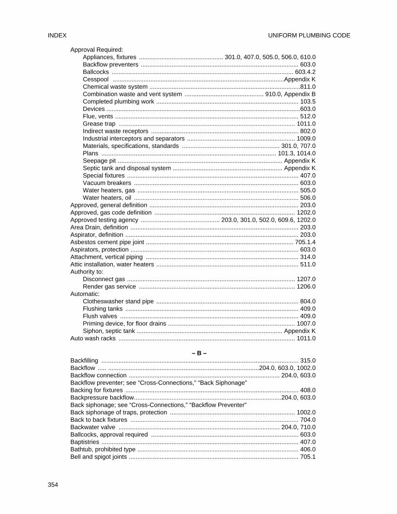
Approval Required:Appliances, fixtures ................................................. 301.0, 407.0, 505.0, 506.0, 610.0Backflow preventers ............................................................................................ 603.0Ballcocks .......................................................................................................... 603.4.2Cesspool ....................................................................................................Appendix KChemical waste system ........................................................................................811.0Combination waste and vent system .............................................. 910.0, Appendix BCompleted plumbing work ................................................................................... 103.5Devices .................................................................................................................603.0Flue, vents ........................................................................................................... 512.0Grease trap ....................................................................................................... 1011.0Indirect waste receptors ...................................................................................... 802.0Industrial interceptors and separators ............................................................... 1009.0Materials, specifications, standards ......................................................... 301.0, 707.0Plans ...................................................................................................... 101.3, 1014.0Seepage pit ................................................................................................ Appendix KSeptic tank and disposal system ................................................................ Appendix KSpecial fixtures .................................................................................................... 407.0Vacuum breakers ................................................................................................ 603.0Water heaters, gas .............................................................................................. 505.0Water heaters, oil ................................................................................................ 506.0
Approved, general definition ....................................................................................... 203.0Approved, gas code definition .................................................................................. 1202.0Approved testing agency .............................................. 203.0, 301.0, 502.0, 609.6, 1202.0Area Drain, definition .................................................................................................. 203.0Aspirator, definition ..................................................................................................... 203.0Asbestos cement pipe joint ...................................................................................... 705.1.4Aspirators, protection .................................................................................................. 603.0Attachment, vertical piping ......................................................................................... 314.0Attic installation, water heaters ................................................................................... 511.0Authority to:
Disconnect gas .................................................................................................. 1207.0Render gas service ........................................................................................... 1206.0
Automatic:Clotheswasher stand pipe ................................................................................... 804.0Flushing tanks ..................................................................................................... 409.0Flush valves ........................................................................................................ 409.0Priming device, for floor drains .......................................................................... 1007.0Siphon, septic tank ..................................................................................... Appendix K
Auto wash racks ....................................................................................................... 1011.0
– B –Backfilling ................................................................................................................... 315.0Backflow ..... ........................................................................................204.0, 603.0, 1002.0Backflow connection ........................................................................................ 204.0, 603.0Backflow preventer; see “Cross-Connections,” “Back Siphonage”Backing for fixtures ..................................................................................................... 408.0Backpressure backflow......................................................................................204.0, 603.0Back siphonage; see “Cross-Connections,” “Backflow Preventer”Back siphonage of traps, protection ......................................................................... 1002.0Back to back fixtures .................................................................................................. 704.0Backwater valve .............................................................................................. 204.0, 710.0Ballcocks, approval required ...................................................................................... 603.0Baptistries ................................................................................................................... 407.0Bathtub, prohibited type .............................................................................................. 406.0Bell and spigot joints ................................................................................................... 705.1
UNIFORM PLUMBING CODEINDEX
354
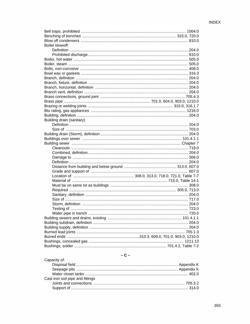
Bell traps, prohibited ................................................................................................. 1004.0Benching of trenches ....................................................................................... 315.0, 720.0Blow off condensers ................................................................................................... 810.0Boiler blowoff:
Definition ..............................................................................................................204.0Prohibited discharge............................................................................................. 810.0
Boiler, hot water .......................................................................................................... 505.0Boiler, steam ............................................................................................................... 505.0Bolts, non-corrosive .................................................................................................... 408.0Bowl wax or gaskets ................................................................................................... 316.3Branch, definition ........................................................................................................ 204.0Branch, fixture, definition ............................................................................................ 204.0Branch, horizontal, definition ...................................................................................... 204.0Branch vent, definition ................................................................................................ 204.0Brass connections, ground joint .............................................................................. 705.4.3Brass pipe ................................................................................ 701.0, 604.0, 903.0, 1210.0Brazing or welding joints ............................................................................... 310.0, 316.1.7Btu rating, gas appliances ........................................................................................ 1216.0Building, definition ........................................................................................................204.0Building drain (sanitary)
Definition .............................................................................................................. 204.0Size of ................................................................................................................. 703.0
Building drain (Storm), definition ................................................................................. 204.0Buildings over sewer ............................................................................................ 101.4.1.1Building sewer ..................................................................................................... Chapter 7
Cleanouts ............................................................................................................ 719.0Combined, definition............................................................................................. 204.0Damage to ........................................................................................................... 306.0Definition ...............................................................................................................204.0Distance from building and below ground ................................................ 313.0, 607.0Grade and support of .......................................................................................... 607.0Location of ........................................................ 308.0, 313.0, 718.0, 721.0, Table 7-7Material of ........................................................................................ 715.0, Table 14-1Must be on same lot as buildings ........................................................................ 308.0Required ................................................................................................... 305.0, 713.0Sanitary, definition ............................................................................................... 204.0Size of .................................................................................................................. 717.0Storm, definition .................................................................................................. 204.0Testing of ............................................................................................................. 723.0Water pipe in trench ............................................................................................ 720.0
Building sewers and drains, existing .................................................................... 101.4.1.1Building subdrain, definition ........................................................................................ 204.0Building supply, definition ........................................................................................... 204.0Burned lead joints .................................................................................................... 705.1.3Burred ends ...................................................................310.3, 609.0, 701.0, 903.0, 1210.0Bushings, concealed gas ........................................................................................ 1211.13Bushings, solder ..................................................................................... 701.4.2, Table 7-2
– C –Capacity of:
Disposal field .............................................................................................. Appendix KSeepage pits .............................................................................................. Appendix KWater closet tanks ............................................................................................... 402.0
Cast iron soil pipe and fittingsJoints and connections ..................................................................................... 705.3.2Support of ............................................................................................................ 314.0
355
INDEX
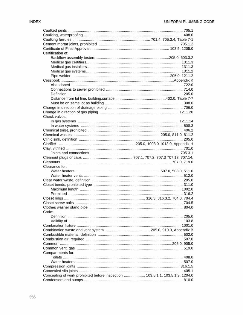
Caulked joints ............................................................................................................. 705.1Caulking, waterproofing .............................................................................................. 408.0Caulking ferrules ......................................................................... 701.4, 705.3.4, Table 7-1Cement mortar joints, prohibited ............................................................................. 705.1.2Certificate of Final Approval ........................................................................... 103.5, 1205.0Certification of:
Backflow assembly testers ......................................................................205.0, 603.3.2Medical gas certifiers.......................................................................................... 1311.3Medical gas installers ......................................................................................... 1311.3Medical gas systems.......................................................................................... 1311.2Pipe welder...............................................................................................205.0, 1211.2
Cesspool: ............................................................................................................Appendix KAbandoned .......................................................................................................... 722.0Connections to sewer prohibited ......................................................................... 714.0Definition ............................................................................................................. 205.0Distance from lot line, building,surface ................................................402.0, Table 7-7Must be on same lot as building .......................................................................... 308.0
Change in direction of drainage piping ....................................................................... 706.0Change in direction of gas piping ........................................................................... 1211.20Check valves:
In gas systems ................................................................................................ 1211.14In water systems ................................................................................................. 608.3
Chemical toilet, prohibited .......................................................................................... 406.2Chemical wastes .................................................................................. 205.0, 811.0, 811.2Clinic sink, definition ................................................................................................... 205.0Clarifier .........................................................................205.0, 1008.0-1013.0, Appendix HClay, vitrified ............................................................................................................... 701.0
Joints and connections ..................................................................................... 705.3.1Cleanout plugs or caps .............................................., 707.1, 707.2, 707.3 707.13, 707.14,Cleanouts ..........................................................................................................707.0, 719.0Clearance for:
Water heaters ................................................................................ 507.0, 508.0, 511.0Water heater vents .............................................................................................. 512.0
Clear water waste, definition ...................................................................................... 205.0Closet bends, prohibited type ..................................................................................... 311.0
Maximum length ................................................................................................ 1002.0Permitted ............................................................................................................. 316.2
Closet rings ............................................................................. 316.3, 316.3.2, 704.0, 704.4Closet screw bolts ...................................................................................................... 704.5Clothes washer stand pipe ......................................................................................... 804.0Code:
Definition ............................................................................................................. 205.0Validity of ............................................................................................................ 103.8
Combination fixture ................................................................................................... 1001.0Combination waste and vent system ........................................... 205.0, 910.0, Appendix BCombustible material, definition ................................................................................. 502.0Combustion air, required ............................................................................................ 507.0Common ...........................................................................................................205.0, 905.0Common vent, gas ..................................................................................................... 519.0Compartments for:
Toilets .................................................................................................................. 408.0Water heaters ...................................................................................................... 507.0
Compression joints .................................................................................................. 316.1.5Concealed slip joints ................................................................................................... 405.1Concealing of work prohibited before inspection .................... 103.5.1.1, 103.5.1.3, 1204.0Condensers and sumps .............................................................................................. 810.0
UNIFORM PLUMBING CODEINDEX
356
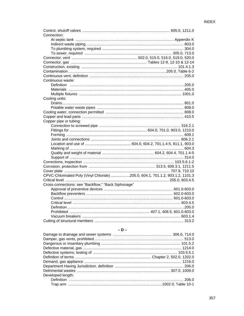
Control, shutoff valves ................................................................................... 605.0, 1211.0Connection:
At septic tank ............................................................................................. Appendix KIndirect waste piping ............................................................................................ 803.0To plumbing system, required ............................................................................. 304.0To sewer, required ................................................................................... 305.0, 713.0
Connector, vent .............................................................. 502.0, 515.0, 516.0, 519.0, 520.0Connector, gas ........................................................................ Tables 12-9, 12-10 & 12-14Construction, existing ........................................................................................... 101.4.1.3Contamination .............................................................................................205.0, Table 6-2Continuous vent, definition ......................................................................................... 205.0Continuous waste:
Definition .............................................................................................................205.0Materials ..............................................................................................................405.0Multiple fixtures ................................................................................................. 1001.0
Cooling units:Drains ................................................................................................................... 801.0Potable water waste pipes .................................................................................. 808.0
Cooling water, connection permitted .......................................................................... 808.0Copper and lead pans ................................................................................................ 410.5Copper pipe or tubing:
Connection to screwed pipe ............................................................................. 316.2.1Fittings for ......................................................................... 604.0, 701.0, 903.0, 1210.0Forming ............................................................................................................... 609.1Joints and connections ..................................................................................... 606.2.1Location and use of ........................................... 604.0, 604.2, 701.1.4-5, 811.1, 903.0Marking of ............................................................................................................ 604.3Quality and weight of material ................................................. 604.2, 604.4, 701.1.4-5Support of ............................................................................................................ 314.0
Corrections, inspection ...................................................................................... 103.5.6.1-2Corrosion, protection from ............................................................... 313.5, 609.3.1, 1211.5Cover plate .................................................................................................... 707.9, 710.10CPVC-Chlorinated Poly (Vinyl Chloride) ..................205.0, 604.1, 701.1.2, 903.1.2, 1101.3Critical level .................................................................................................. 205.0, 603.4.5Cross-connections: see “Backflow,” “Back Siphonage”
Approval of preventive devices ................................................................. 601.0-603.0Backflow preventers .................................................................................. 602.0-603.0Control ....................................................................................................... 601.0-603.0Critical level ...................................................................................................... 603.4.5Definition ...............................................................................................................205.0Prohibited ............................................................................ 407.1, 408.5, 601.0-603.0Vacuum breakers ............................................................................................. 603.1.4
Cutting of structural members .................................................................................... 313.2
– D –Damage to drainage and sewer systems ........................................................ 306.0, 714.0Damper, gas vents, prohibited .................................................................................... 513.0Dangerous or insanitary plumbing ........................................................................... 101.5.2Defective material, gas ............................................................................................. 1214.0Defective systems, testing of ................................................................................ 103.5.5.1Definition of terms ........................................................................ Chapter 2, 502.0, 1202.0Demand, gas appliance ............................................................................................ 1216.0Department Having Jurisdiction, definition ................................................................. 206.0Detrimental wastes ........................................................................................ 307.0, 1009.0Developed length:
Definition ............................................................................................................. 206.0Trap arm .........................................................................................1002.0, Table 10-1
357
INDEX
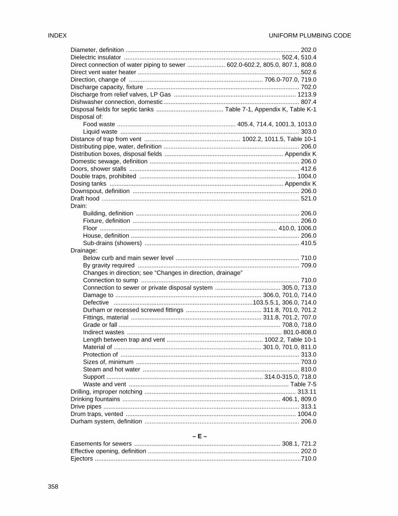
Diameter, definition ..................................................................................................... 202.0Dielectric insulator ........................................................................................... 502.4, 510.4Direct connection of water piping to sewer ...................... 602.0-602.2, 805.0, 807.1, 808.0Direct vent water heater ...............................................................................................502.6Direction, change of .............................................................................. 706.0-707.0, 719.0Discharge capacity, fixture ......................................................................................... 702.0Discharge from relief valves, LP Gas ....................................................................... 1213.9Dishwasher connection, domestic ............................................................................... 807.4Disposal fields for septic tanks ....................................... Table 7-1, Appendix K, Table K-1Disposal of:
Food waste ..................................................................... 405.4, 714.4, 1001.3, 1013.0Liquid waste ........................................................................................................ 303.0
Distance of trap from vent ........................................................ 1002.2, 1011.5, Table 10-1Distributing pipe, water, definition ............................................................................... 206.0Distribution boxes, disposal fields ..................................................................... Appendix KDomestic sewage, definition ....................................................................................... 206.0Doors, shower stalls ................................................................................................... 412.6Double traps, prohibited ........................................................................................... 1004.0Dosing tanks ..................................................................................................... Appendix KDownspout, definition ................................................................................................. 206.0Draft hood ................................................................................................................... 521.0Drain:
Building, definition ............................................................................................... 206.0Fixture, definition ................................................................................................. 206.0Floor ....................................................................................................... 410.0, 1006.0House, definition .................................................................................................. 206.0Sub-drains (showers) .......................................................................................... 410.5
Drainage:Below curb and main sewer level ........................................................................ 710.0By gravity required .............................................................................................. 709.0Changes in direction; see “Changes in direction, drainage”Connection to sump ............................................................................................ 710.0Connection to sewer or private disposal system ...................................... 305.0, 713.0Damage to ..................................................................................... 306.0, 701.0, 714.0Defective .................................................................................103.5.5.1, 306.0, 714.0Durham or recessed screwed fittings ............................................ 311.8, 701.0, 701.2Fittings, material ............................................................................ 311.8, 701.2, 707.0Grade or fall .............................................................................................. 708.0, 718.0Indirect wastes .......................................................................................... 801.0-808.0Length between trap and vent ........................................................ 1002.2, Table 10-1Material of ...................................................................................... 301.0, 701.0, 811.0Protection of ........................................................................................................ 313.0Sizes of, minimum ............................................................................................... 703.0Steam and hot water ........................................................................................... 810.0Support ........................................................................................... 314.0-315.0, 718.0Waste and vent ............................................................................................. Table 7-5
Drilling, improper notching ........................................................................................ 313.11Drinking fountains ............................................................................................ 406.1, 809.0Drive pipes .................................................................................................................. 313.1Drum traps, vented ................................................................................................... 1004.0Durham system, definition .......................................................................................... 206.0
– E –Easements for sewers ..................................................................................... 308.1, 721.2Effective opening, definition ........................................................................................ 202.0Ejectors ........................................................................................................................710.0
UNIFORM PLUMBING CODEINDEX
358
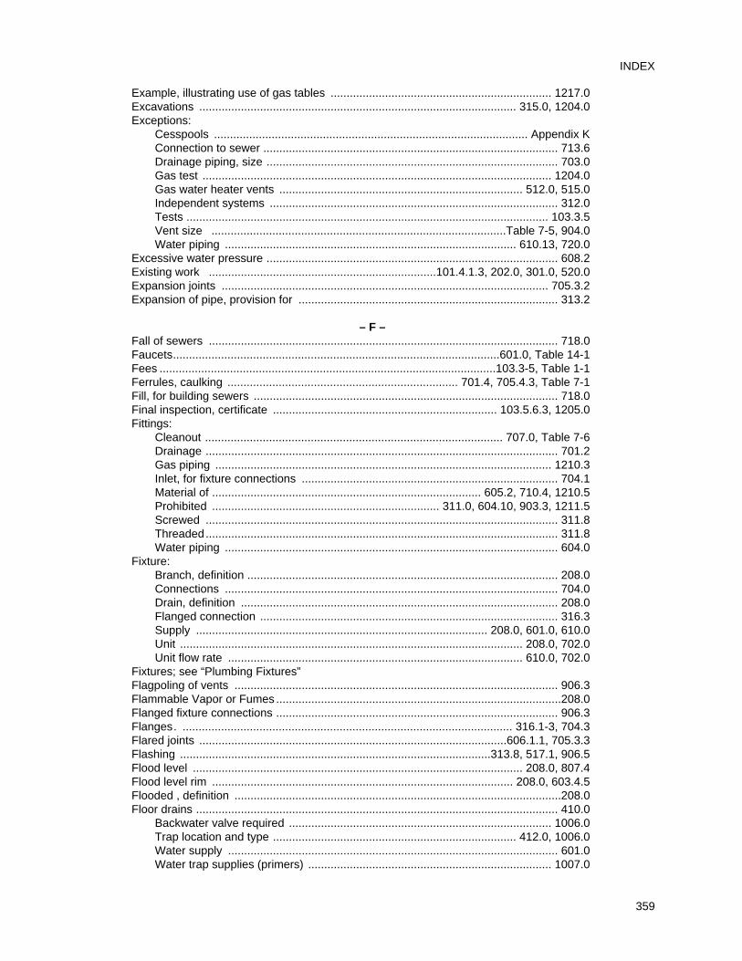
Example, illustrating use of gas tables ..................................................................... 1217.0Excavations ................................................................................................... 315.0, 1204.0Exceptions:
Cesspools .................................................................................................. Appendix KConnection to sewer ............................................................................................ 713.6Drainage piping, size ........................................................................................... 703.0Gas test ............................................................................................................. 1204.0Gas water heater vents ............................................................................ 512.0, 515.0Independent systems .......................................................................................... 312.0Tests ................................................................................................................. 103.3.5Vent size ............................................................................................Table 7-5, 904.0Water piping ........................................................................................... 610.13, 720.0
Excessive water pressure ........................................................................................... 608.2Existing work .......................................................................101.4.1.3, 202.0, 301.0, 520.0Expansion joints ...................................................................................................... 705.3.2Expansion of pipe, provision for ................................................................................. 313.2
– F –Fall of sewers ............................................................................................................. 718.0Faucets......................................................................................................601.0, Table 14-1Fees .........................................................................................................103.3-5, Table 1-1Ferrules, caulking ........................................................................ 701.4, 705.4.3, Table 7-1Fill, for building sewers ............................................................................................... 718.0Final inspection, certificate ...................................................................... 103.5.6.3, 1205.0Fittings:
Cleanout ............................................................................................. 707.0, Table 7-6Drainage .............................................................................................................. 701.2Gas piping ......................................................................................................... 1210.3Inlet, for fixture connections ................................................................................ 704.1Material of .................................................................................... 605.2, 710.4, 1210.5Prohibited ....................................................................... 311.0, 604.10, 903.3, 1211.5Screwed .............................................................................................................. 311.8Threaded.............................................................................................................. 311.8Water piping ........................................................................................................ 604.0
Fixture:Branch, definition ................................................................................................. 208.0Connections ........................................................................................................ 704.0Drain, definition ................................................................................................... 208.0Flanged connection ............................................................................................. 316.3Supply ........................................................................................... 208.0, 601.0, 610.0Unit ........................................................................................................... 208.0, 702.0Unit flow rate ............................................................................................ 610.0, 702.0
Fixtures; see “Plumbing Fixtures”Flagpoling of vents ..................................................................................................... 906.3Flammable Vapor or Fumes .........................................................................................208.0Flanged fixture connections ........................................................................................ 906.3Flanges. ....................................................................................................... 316.1-3, 704.3Flared joints ................................................................................................606.1.1, 705.3.3Flashing .................................................................................................313.8, 517.1, 906.5Flood level ....................................................................................................... 208.0, 807.4Flood level rim .............................................................................................. 208.0, 603.4.5Flooded , definition ......................................................................................................208.0Floor drains ................................................................................................................. 410.0
Backwater valve required .................................................................................. 1006.0Trap location and type ............................................................................ 412.0, 1006.0Water supply ....................................................................................................... 601.0Water trap supplies (primers) ............................................................................ 1007.0
359
INDEX
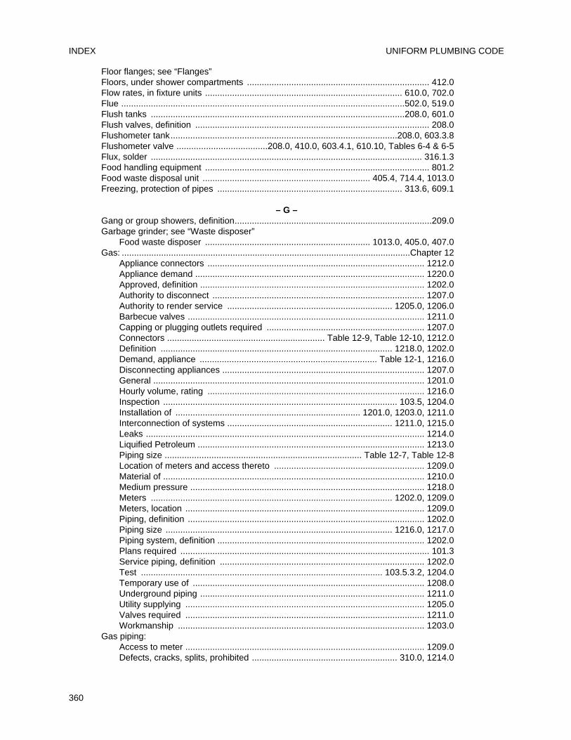
Floor flanges; see “Flanges”Floors, under shower compartments .......................................................................... 412.0Flow rates, in fixture units ................................................................................ 610.0, 702.0Flue ...................................................................................................................502.0, 519.0Flush tanks .......................................................................................................208.0, 601.0Flush valves, definition ............................................................................................... 208.0Flushometer tank............................................................................................208.0, 603.3.8Flushometer valve .....................................208.0, 410.0, 603.4.1, 610.10, Tables 6-4 & 6-5Flux, solder .............................................................................................................. 316.1.3Food handling equipment ........................................................................................... 801.2Food waste disposal unit .................................................................... 405.4, 714.4, 1013.0Freezing, protection of pipes ........................................................................... 313.6, 609.1
– G –Gang or group showers, definition................................................................................209.0Garbage grinder; see “Waste disposer”
Food waste disposer ................................................................... 1013.0, 405.0, 407.0Gas: .....................................................................................................................Chapter 12
Appliance connectors ........................................................................................ 1212.0Appliance demand ............................................................................................. 1220.0Approved, definition ........................................................................................... 1202.0Authority to disconnect ...................................................................................... 1207.0Authority to render service ................................................................... 1205.0, 1206.0Barbecue valves ................................................................................................ 1211.0Capping or plugging outlets required ................................................................ 1207.0Connectors ................................................................ Table 12-9, Table 12-10, 1212.0Definition .............................................................................................. 1218.0, 1202.0Demand, appliance ........................................................................ Table 12-1, 1216.0Disconnecting appliances .................................................................................. 1207.0General .............................................................................................................. 1201.0Hourly volume, rating ........................................................................................ 1216.0Inspection ............................................................................................... 103.5, 1204.0Installation of ........................................................................... 1201.0, 1203.0, 1211.0Interconnection of systems ................................................................... 1211.0, 1215.0Leaks ................................................................................................................. 1214.0Liquified Petroleum ............................................................................................ 1213.0Piping size ................................................................................ Table 12-7, Table 12-8Location of meters and access thereto ............................................................. 1209.0Material of .......................................................................................................... 1210.0Medium pressure ............................................................................................... 1218.0Meters .................................................................................................. 1202.0, 1209.0Meters, location ................................................................................................. 1209.0Piping, definition ................................................................................................ 1202.0Piping size ............................................................................................ 1216.0, 1217.0Piping system, definition .................................................................................... 1202.0Plans required ..................................................................................................... 101.3Service piping, definition ................................................................................... 1202.0Test .................................................................................................. 103.5.3.2, 1204.0Temporary use of .............................................................................................. 1208.0Underground piping ........................................................................................... 1211.0Utility supplying ................................................................................................. 1205.0Valves required ................................................................................................. 1211.0Workmanship .................................................................................................... 1203.0
Gas piping: Access to meter ................................................................................................. 1209.0Defects, cracks, splits, prohibited ........................................................... 310.0, 1214.0
UNIFORM PLUMBING CODEINDEX
360
Definition ........................................................................................................... 1202.0Inspection and testing .......................................................................... 1204.0, 1205.0Installation ............................................................................................ 1203.0, 1211.0Material .............................................................................................................. 1210.0Required gas supply .......................................................................................... 1216.0Size ..... .................................................................................................1216.0, 1217.0Shutoff valves and cocks ...................................................................... 1211.0, 1213.0Supporting fixtures ............................................................................................ 1203.0Unions ............................................................................................................... 1211.0
Gas water heater; see definition ................................................................................. 502.0Access and working space to .............................................................................. 511.0Approval requirements ........................................................................................ 505.0Clearances ............................................................................................... 508.0, 511.0Combustion air required .......................................................... Table 5-1, 506.0, 507.0Draft hoods .......................................................................................................... 521.0Enclosures ........................................................................................................... 507.0Energy cut-off (ECO) ........................................................................................... 505.0Inspections .......................................................................................................... 504.0Oil burning or other .............................................................................................. 506.0Permits required .................................................................................................. 503.0Pressure relief valves .......................................................................................... 608.0Prohibited locations ................................................................................ 1213.0, 509.0Protection ...................................................................................... 505.0, 506.0, 510.0Sealed combustion ........................................................................ 502.0, 509.0, 510.0Secondary temperature limiting device ............................................................... 505.0Vent required ....................................................................................................... 512.0
Gas water heater vent:Approved type required ....................................................................................... 512.0Area of ................................................................................ 518.0, 519.0, 520.0, 522.0Clearances ............................................................................................... 512.0, 516.0Common vent ...................................................................................................... 519.0Connector ...................................................................................... 514.0, 516.0, 523.0Damper prohibited ............................................................................................... 513.0Definitions ............................................................................................................ 502.0Draft hoods .......................................................................................................... 521.0Engineered system .............................................................................................. 512.0Existing masonry chimneys ................................................................................. 522.0Existing venting systems ..................................................................................... 520.0Hood, cap or cowl ................................................................................................ 517.0Inspections .......................................................................................................... 504.0Interlock, control ....................................................................................... 524.0, 525.0Limitation ............................................................................................................. 513.0Location and support ........................................................................................... 515.0Location of draft hood and connectors ................................................................ 521.0Manifolding of ........................................................................................... 519.0, 523.0Material ..................................................................................................... 512.0, 513.0Maximum flue gas temperature ........................................................................... 502.0Maximum length of .............................................................................................. 516.0Mechanical draft systems .................................................................................... 524.0Protection and support ........................................................................................ 515.0Required .............................................................................................................. 512.0Rise per lineal foot ............................................................................................... 516.0Sealed combustion ................................................................................... 509.0, 510.0Size of ................................................................................................................. 518.0Termination ......................................................................................................... 517.0
361
INDEX
Grade:Building sewer ..................................................................................................... 718.0Definition ...............................................................................................................209.0Horizontal drainage ............................................................................................. 708.0
Gravity drainage required ........................................................................................... 709.0Gravity supply tanks ................................................................................................... 607.0Graywater systems .............................................................................................Appendix GGrease interceptors: ...................................................................... Chapter 10, Appendix H
Where required ..................................................................................... 1009.0-1014.0Definition ............................................................................................................. 209.0Design and construction ............................................................................ Appendix H
Grease traps:Construction and design .................................................................................... 1014.0Definition ............................................................................................................. 209.0Sizes ........................................................................................................... Table 10-2
Ground joint connections ......................................................................................... 705.4.3Grounding ................................................................................................................... 604.8
– H –Hangers; see “Supports”Harmful waste; see “Waste, detrimental and harmful”Health and safety ............................................................................... 101.2, 101.5.2, 301.0High hazard .................................................................................................210.0, Table 6-1Horizontal branch ............................................................................................ 210.0, 703.0Horizontal pipe, definition ........................................................................................... 210.0Horizontal to horizontal drainage fittings .................................................................... 706.0Horizontal to vertical drainage fittings ......................................................................... 706.0Horizontal vent pipes ................................................................................. Table 7-5, 904.0Hose connections ....................................................................................... 603.2.1, 1212.0Hot mopped shower pans; see “Shower pans”Hot water boiler ............................................................ 505.0, 506.0, 603.3.10, Table 14-1Hot water pipe sizing .................................................................................................. 610.0House drain; see “Building sewer”House sewer, see “Building sewer”
– I –Identification:
Copper tubing ...................................................................................................... 604.3Gas piping .......................................................................................... 1210.0, 1211.19Piping, fittings, traps, and fixtures .......................................................... 301.0, 1003.1Required .............................................................................................................. 301.0Water lines, non-potable ................................................................................ 603.4.11
Increasers ............................................................................................. 311.0, 316.4, 317.0Independent system of sewers ................................................................................... 312.0Indirect waste piping:
Approval required ................................................................................................ 802.0Cleanouts ............................................................................................................ 803.0Connections ............................................................................................. 801.0, 805.0Definition ............................................................................................................. 202.0Hot water ............................................................................................................. 810.0Maximum length .................................................................................................. 803.0Required .............................................................................................................. 801.0Size of ................................................................................................................. 803.0Steam and hot water ........................................................................................... 811.1Vents ................................................................................................................... 803.0
UNIFORM PLUMBING CODEINDEX
362
Indirect waste:Appliances ........................................................................................................... 807.0Condensers and sumps ...................................................................................... 811.1Cooling water ...................................................................................................... 808.0Drinking fountains ................................................................................................ 809.0Food handling equipment .................................................................................... 801.2Sterilizing equipment ........................................................................................... 806.0
Indirect waste receptors:Approval required ................................................................................................ 802.0For clotheswashers ............................................................................................. 804.0Materials .............................................................................................................. 803.0Prohibited location ............................................................................................... 804.1Required water supply ............................................................................ 601.0, 1007.0Size of ................................................................................................................. 804.1
Individual vent ..............................................................................211.0, Table 7-5, 1014.0Industrial interceptors and separators ............................................. 1008.0-1012.0, 1009.0Industrial wastes .............................................................................................. 211.0, 307.0
Approval required ................................................................................... 811.1, 1008.2Disposal ............................................................................................................... 811.0Materials .................................................................................................811.2, 1009.2Pretreatment ........................................................................................................ 811.1
Inlet fittings for fixture connections ............................................................................. 704.2Insanitary:
Construction .................................................................................................. 101.4.1.3Definition ............................................................................................................. 211.0
Inspection and testing:Abandoned sewers, cesspools ............................................................ 721.0, K 1-K 11Advance notice for ............................................................................ 103.5.4.1, 1204.0Building sewer ..................................................................................................... 723.0Certificate ......................................................................................... 103.5.6.3, 1205.0Concealment of work prohibited before inspection .......................... 103.5.1.3, 1204.0Disposal fields ............................................................................................ Appendix KFinal ........................................................................................103.5.6.3, 504.0, 1204.0Flues and vents ................................................................................................... 504.0Gas piping, rough and final ............................................................................... 1204.0Labor and material for ...................................................................... 103.5.4.3, 1204.0Water heaters ...................................................................................................... 504.0Water piping ................................................................................. 103.5.1.1, 103.5.3.1
lnspector; see “Administrative Authority”Installation of:
Building sewer: .............................................................................. 715.0, 717.0, 718.0Cleanouts ..................................................................... 707.0, 719.0, 803.0, Table 7-6Devices to prevent cross-connections ...................................................... 602.0, 603.0Drainage piping system ................................................................................ Chapter 7Fixtures ................................................................................................................ 408.0Floor drains and shower stalls ............................................................................. 410.0Gas piping systems ........................................................................................... 1211.0Overflows ............................................................................................................ 404.0Urinals ...................................................................................................... 406.0, 409.0Vents ............................................................................................................ Chapter 9Water piping system ............................................................................................ 609.0
Insulator, dielectric ........................................................................................... 502.0, 510.0Intake, air, vent termination near ................................................................................ 906.2Integral traps ........................................................................................... 1001.1, Table 7-3Intercepting hoppers or sink; see “Receptors”
363
INDEX
Interceptors:Abandoned ...................................................................................................... H 108.0Auto wash rack .................................................................................................. 1011.0Cleaning required ............................................................................................ H 104.1Cleanouts, location ............................................................................... 707.8, H 103.2Commercial ....................................................................................... 1014.10, H 101.0Definition ............................................................................................................. 209.0Design .............................................................................................................. H 103.0Effluent sampling ............................................................................................. H 107.0Grease ...................................................................................1009.0-1015.0, H 101.0Industrial ............................................................................................................1009.0Location .............................................................................................. 1009.5, H 104.0Maintenance ...................................................................... 101.4.1.2, 1009.5, H 104.0Packing establishments ..................................................................................... 1010.0Required ............................................................................................................ 1009.0Sizing ............................................................................................................... H 106.0Slaughterhouse ................................................................................................. 1010.0Vent ..................................................................................................................... 902.0Waste discharge requirements ........................................................................ H 102.0
Intermixing of metals prohibited ............................................................ 311.6, 510.0, 604.1Invert, definition .......................................................................................................... 211.0Iron Pipe Size (IPS) pipe ............................................................................................ 302.0Island fixture, venting .................................................................................................. 909.0
– J –Joints and connections:
Additives prohibited ............................................................................................. 705.1Brazing .................................................................................... 212.0, 316.1.7, 609.3.2Cast iron ................................................................................................705.1, 705.3.2Cement mortar, prohibited ................................................................................ 705.1.2Compounds, thread lubricants ................................................. 316.1.1, 707.3, 1211.1Compression ...................................................................................... 316.1.5, 606.2.1Copper to iron ........................................................................................ 311.6, 316.2.1Copper tube ........................................................................................ 316.2.1, 606.2.1Earthenware to metal ....................................................................................... 316.3.1Elastomeric gasketed ....................................................................................... 705.1.7Expansion ......................................................................................................... 705.4.2Fixture ...................................................................................................... 316.3, 408.0Flexible ............................................................................................................. 316.1.5Floor-mounted .......................................................................................... 316.3, 704.3Gas and watertight ........................................................................................ 103.5.3.7Gas piping ......................................................................................................... 1211.1Ground joint unions .......................................................................................... 705.4.3Hubless cast iron................................................................................................705.1.9Increasers and reducers ...................................................................................... 317.0Lead ........................................................................................ 316.1.2, 705.1, 705.3.4Mechanical ....................................................................................................... 606.1.2Molded rubber .................................................................................................. 705.1.6Prohibited fittings and practices .................................................... 311.0, 316.4, 317.0Rubber ring ....................................................................................................... 705.1.7Screwed ........................................................................................................... 316.1.1Shield coupling...................................................................................................705.1.8Slip .......................................................................................... 405.1, 705.4.1, 1003.2Soldered or sweat ................................................................................. 212.0, 316.1.3Solvent cement ................................................................................................. 316.1.6Special ................................................................................................................. 316.2
UNIFORM PLUMBING CODEINDEX
364
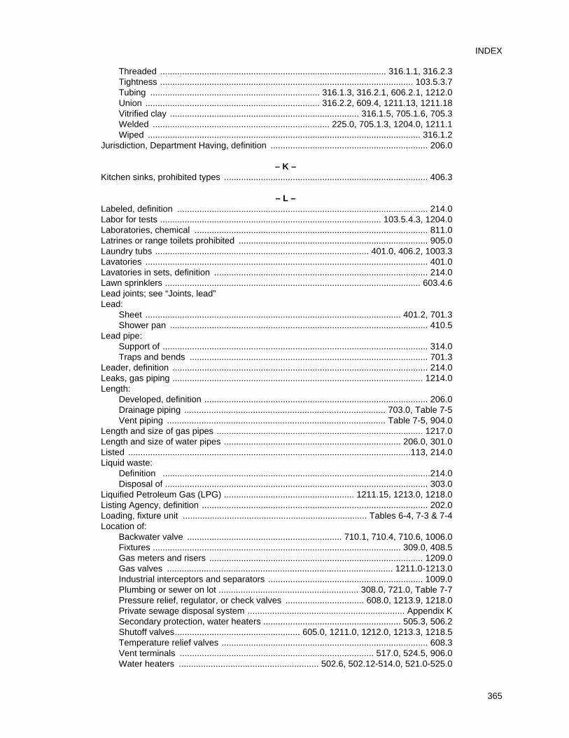
Threaded ............................................................................................ 316.1.1, 316.2.3Tightness ....................................................................................................... 103.5.3.7Tubing ..................................................................... 316.1.3, 316.2.1, 606.2.1, 1212.0Union ....................................................................... 316.2.2, 609.4, 1211.13, 1211.18Vitrified clay ............................................................................. 316.1.5, 705.1.6, 705.3Welded ........................................................................ 225.0, 705.1.3, 1204.0, 1211.1Wiped ............................................................................................................... 316.1.2
Jurisdiction, Department Having, definition ................................................................ 206.0
– K –Kitchen sinks, prohibited types ................................................................................... 406.3
– L –Labeled, definition ...................................................................................................... 214.0Labor for tests .......................................................................................... 103.5.4.3, 1204.0Laboratories, chemical ............................................................................................... 811.0Latrines or range toilets prohibited ............................................................................. 905.0Laundry tubs ....................................................................................... 401.0, 406.2, 1003.3Lavatories ................................................................................................................... 401.0Lavatories in sets, definition ....................................................................................... 214.0Lawn sprinklers ........................................................................................................ 603.4.6Lead joints; see “Joints, lead”Lead:
Sheet ........................................................................................................ 401.2, 701.3Shower pan ......................................................................................................... 410.5
Lead pipe:Support of ............................................................................................................ 314.0Traps and bends ................................................................................................. 701.3
Leader, definition ........................................................................................................ 214.0Leaks, gas piping ...................................................................................................... 1214.0Length:
Developed, definition ........................................................................................... 206.0Drainage piping .................................................................................. 703.0, Table 7-5Vent piping ......................................................................................... Table 7-5, 904.0
Length and size of gas pipes .................................................................................... 1217.0Length and size of water pipes ........................................................................ 206.0, 301.0Listed ...................................................................................................................113, 214.0Liquid waste:
Definition .............................................................................................................214.0Disposal of ........................................................................................................... 303.0
Liquified Petroleum Gas (LPG) ..................................................... 1211.15, 1213.0, 1218.0Listing Agency, definition ............................................................................................ 202.0Loading, fixture unit ........................................................................... Tables 6-4, 7-3 & 7-4Location of:
Backwater valve ............................................................... 710.1, 710.4, 710.6, 1006.0Fixtures ..................................................................................................... 309.0, 408.5Gas meters and risers ....................................................................................... 1209.0Gas valves ............................................................................................ 1211.0-1213.0Industrial interceptors and separators ............................................................... 1009.0Plumbing or sewer on lot ......................................................... 308.0, 721.0, Table 7-7Pressure relief, regulator, or check valves ................................ 608.0, 1213.9, 1218.0Private sewage disposal system ................................................................ Appendix KSecondary protection, water heaters ........................................................ 505.3, 506.2Shutoff valves................................................... 605.0, 1211.0, 1212.0, 1213.3, 1218.5Temperature relief valves .................................................................................... 608.3Vent terminals ............................................................................... 517.0, 524.5, 906.0Water heaters ......................................................... 502.6, 502.12-514.0, 521.0-525.0
365
INDEX
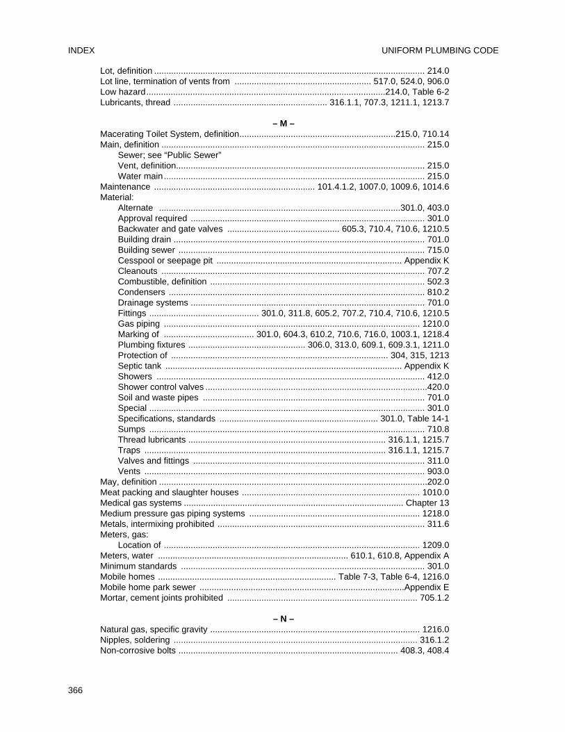
Lot, definition ............................................................................................................... 214.0Lot line, termination of vents from ........................................................ 517.0, 524.0, 906.0Low hazard..................................................................................................214.0, Table 6-2Lubricants, thread ............................................................... 316.1.1, 707.3, 1211.1, 1213.7
– M –Macerating Toilet System, definition................................................................215.0, 710.14Main, definition ............................................................................................................ 215.0
Sewer; see “Public Sewer”Vent, definition...................................................................................................... 215.0Water main ........................................................................................................... 215.0
Maintenance .................................................................. 101.4.1.2, 1007.0, 1009.6, 1014.6Material:
Alternate ...................................................................................................301.0, 403.0Approval required ................................................................................................ 301.0Backwater and gate valves .............................................. 605.3, 710.4, 710.6, 1210.5Building drain ....................................................................................................... 701.0Building sewer ..................................................................................................... 715.0Cesspool or seepage pit ............................................................................ Appendix KCleanouts ............................................................................................................ 707.2Combustible, definition ........................................................................................ 502.3Condensers ......................................................................................................... 810.2Drainage systems ................................................................................................ 701.0Fittings ............................................. 301.0, 311.8, 605.2, 707.2, 710.4, 710.6, 1210.5Gas piping ......................................................................................................... 1210.0Marking of ..................................... 301.0, 604.3, 610.2, 710.6, 716.0, 1003.1, 1218.4Plumbing fixtures ................................................ 306.0, 313.0, 609.1, 609.3.1, 1211.0Protection of ......................................................................................... 304, 315, 1213Septic tank ................................................................................................. Appendix KShowers .............................................................................................................. 412.0Shower control valves ...........................................................................................420.0Soil and waste pipes ........................................................................................... 701.0Special ................................................................................................................. 301.0Specifications, standards ................................................................. 301.0, Table 14-1Sumps ................................................................................................................. 710.8Thread lubricants ................................................................................. 316.1.1, 1215.7Traps ................................................................................................... 316.1.1, 1215.7Valves and fittings ............................................................................................... 311.0Vents ................................................................................................................... 903.0
May, definition ..............................................................................................................202.0Meat packing and slaughter houses ......................................................................... 1010.0Medical gas systems .......................................................................................... Chapter 13Medium pressure gas piping systems ...................................................................... 1218.0Metals, intermixing prohibited ..................................................................................... 311.6Meters, gas:
Location of ......................................................................................................... 1209.0Meters, water .............................................................................. 610.1, 610.8, Appendix AMinimum standards .................................................................................................... 301.0Mobile homes ......................................................................... Table 7-3, Table 6-4, 1216.0Mobile home park sewer ....................................................................................Appendix EMortar, cement joints prohibited .............................................................................. 705.1.2
– N –Natural gas, specific gravity ...................................................................................... 1216.0Nipples, soldering .................................................................................................... 316.1.2Non-corrosive bolts .......................................................................................... 408.3, 408.4
UNIFORM PLUMBING CODEINDEX
366
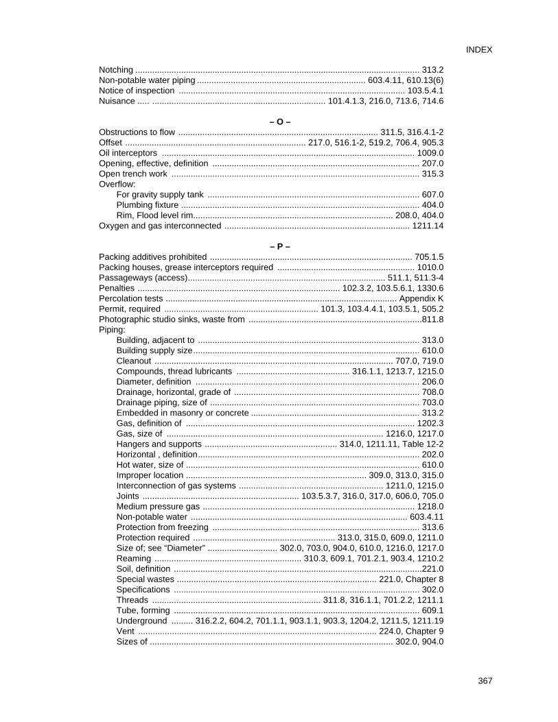
Notching ...................................................................................................................... 313.2Non-potable water piping ...................................................................... 603.4.11, 610.13(6)Notice of inspection .............................................................................................. 103.5.4.1Nuisance ..... ........................................................................ 101.4.1.3, 216.0, 713.6, 714.6
– O –Obstructions to flow ................................................................................... 311.5, 316.4.1-2Offset ........................................................................... 217.0, 516.1-2, 519.2, 706.4, 905.3Oil interceptors ......................................................................................................... 1009.0Opening, effective, definition ...................................................................................... 207.0Open trench work ....................................................................................................... 315.3Overflow:
For gravity supply tank ........................................................................................ 607.0Plumbing fixture ................................................................................................... 404.0Rim, Flood level rim................................................................................... 208.0, 404.0
Oxygen and gas interconnected ............................................................................. 1211.14
– P –Packing additives prohibited .................................................................................... 705.1.5Packing houses, grease interceptors required ......................................................... 1010.0Passageways (access).................................................................................. 511.1, 511.3-4Penalties .................................................................................... 102.3.2, 103.5.6.1, 1330.6Percolation tests ................................................................................................ Appendix KPermit, required ................................................................ 101.3, 103.4.4.1, 103.5.1, 505.2Photographic studio sinks, waste from ........................................................................811.8Piping:
Building, adjacent to ............................................................................................ 313.0Building supply size.............................................................................................. 610.0Cleanout ................................................................................................... 707.0, 719.0Compounds, thread lubricants ............................................... 316.1.1, 1213.7, 1215.0Diameter, definition ............................................................................................. 206.0Drainage, horizontal, grade of ............................................................................. 708.0Drainage piping, size of ....................................................................................... 703.0Embedded in masonry or concrete ...................................................................... 313.2Gas, definition of ............................................................................................... 1202.3Gas, size of .......................................................................................... 1216.0, 1217.0Hangers and supports ....................................................... 314.0, 1211.11, Table 12-2Horizontal , definition............................................................................................ 202.0Hot water, size of ................................................................................................. 610.0Improper location ........................................................................... 309.0, 313.0, 315.0Interconnection of gas systems ............................................................ 1211.0, 1215.0Joints ................................................................. 103.5.3.7, 316.0, 317.0, 606.0, 705.0Medium pressure gas ........................................................................................ 1218.0Non-potable water .......................................................................................... 603.4.11Protection from freezing ...................................................................................... 313.6Protection required ........................................................... 313.0, 315.0, 609.0, 1211.0Size of; see “Diameter” ............................. 302.0, 703.0, 904.0, 610.0, 1216.0, 1217.0Reaming ............................................................. 310.3, 609.1, 701.2.1, 903.4, 1210.2Soil, definition .......................................................................................................221.0Special wastes ................................................................................... 221.0, Chapter 8Specifications ...................................................................................................... 302.0Threads ...................................................................... 311.8, 316.1.1, 701.2.2, 1211.1Tube, forming ...................................................................................................... 609.1Underground ......... 316.2.2, 604.2, 701.1.1, 903.1.1, 903.3, 1204.2, 1211.5, 1211.19Vent ................................................................................................... 224.0, Chapter 9Sizes of ..................................................................................................... 302.0, 904.0
367
INDEX
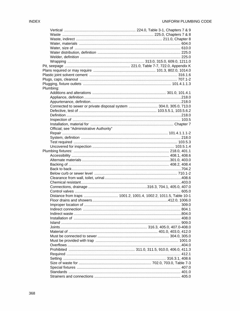
Vertical ..................................................................... 224.0, Table 3-1, Chapters 7 & 9Waste ........................................................................................ 225.0, Chapters 7 & 8Waste, indirect ................................................................................... 211.0, Chapter 8Water, materials .................................................................................................. 604.0Water, size of ...................................................................................................... 610.0Water distribution, definition ................................................................................ 225.0Welder, definition ................................................................................................. 225.0Wrapping .......................................................................... 313.0, 315.0, 609.0, 1211.0
Pit, seepage ............................................................... 221.0, Table 7-7, 722.0, Appendix KPlans required or may require ............................................................ 101.3, 802.0, 1014.0Plastic joint solvent cement ..................................................................................... 316.1.6Plugs, caps, cleanout .............................................................................................. 707.1-2Plugging, fixture outlets ..................................................................................... 101.4.1.1.3Plumbing:
Additions and alterations ....................................................................... 301.0, 101.4.1Appliance, definition ..............................................................................................218.0Appurtenance, definition........................................................................................218.0Connected to sewer or private disposal system ............................ 304.0, 305.0, 713.0Defective, test of ........................................................................... 103.5.5.1, 103.5.6.2Definition ...............................................................................................................218.0Inspection of ........................................................................................................ 103.5Installation, material for ................................................................................ Chapter 7Official; see “Administrative Authority”Repair ...................................................................................................... 101.4.1.1.1-2System, definition ................................................................................................ 218.0Test required .................................................................................................... 103.5.3Uncovered for inspection ............................................................................... 103.5.1.4
Plumbing fixtures: ............................................................................................ 218.0, 401.1Accessibility .............................................................................................. 408.1, 408.6Alternate materials .....................................................................................301.0, 403.0Backing of ................................................................................................. 408.2, 408.4Back to back..........................................................................................................704.2Below curb or sewer level ................................................................................ 710.1-2Clearance from wall, toilet, urinal ..........................................................................408.6Chemical resistant.................................................................................................403.0Connections, drainage .........................................................316.3, 704.1, 405.0, 407.0Control valves ...................................................................................................... 605.0Distance from traps ................................. 1001.2, 1001.4, 1002.2, 1011.5, Table 10-1Floor drains and showers .........................................................................412.0, 1006.0Improper location of ............................................................................................. 309.0Indirect connection .............................................................................................. 804.1Indirect waste ........................................................................................................804.0Installation of ....................................................................................................... 408.0Island ................................................................................................................... 909.0Joints.................................................................................... 316.3, 405.0, 407.0-408.0Material of ...................................................................................... 401.0, 403.0, 412.0Must be connected to sewer ..................................................................... 304.0, 305.0Must be provided with trap ................................................................................ 1001.0Overflows ..............................................................................................................404.0Prohibited ................................................................ 311.0, 311.5, 910.0, 406.0, 411.3Required .............................................................................................................. 412.1Setting ................................................................................................... 316.3.1, 408.6Size of waste for ...................................................................... 702.0, 703.0, Table 7-3Special fixtures .................................................................................................... 407.0Standards ............................................................................................................ 401.0Strainers and connections ................................................................................... 405.0
UNIFORM PLUMBING CODEINDEX
368
Supply and waste connection, access to ................................................. 405.0, 405.2Supply fittings ........................................................................................... 408.8, 603.2Unit equivalent .............................................. 610, 702.0, 703.0, Tables 6-3, 7-3 & 7-4Water supply required ......................................................................................... 601.0
Polyethylene (PE) ....................................................................................................... 604.1Cross-linked Polypropylene (PEX), definition...............................................................218.0Polypropylene (PP), definition ......................................................................................218.0Polyvinyl Chloride (PVC) ........................................................... 218.0, 604.0, 701.1, 701.2Pollution .............................................................................................................218.0, 1003Potable water:
Definition ............................................................................................................. 218.0Protection of ............................................................................................. 602.0, 603.0Supply required ................................................................................................... 601.0Unlawful connection to ........................................................................................ 602.0
Poured joints ............................................................................................................ 705.1.2Pressure drainage connections prohibited ................................................................. 805.0Pressure, excessive, water ......................................................................................... 608.2Pressure losses, water ............................................................................................... 610.0Pressure, medium gas .............................................................................................. 1218.0Pressure regulator, when required .......................................................................... 608.2-6Pressure, regular, gas .............................................................................................. 1218.0Pressure relief valve ............................................................................. 608.0, 505.3, 506.2Preventer, backflow ......................................................................................... 204.0, 603.2Primary settling tank ................................................................................................... 902.1Private or private use, definition ...................................................................................218.0Private sewage:
Capacity of system ..................................................................................... Appendix KConstruction ............................................................................................... Appendix KDisposal system .............................................................................. 218.0, Appendix KGeneral ..................................................................................... 103.5.1.3, Appendix KLocation ......................................................................... 721.0, Table 7-7, Appendix K
Private sewer, definition ..............................................................................................218.0Private water supply ........................................................................................ 602.2, 602.4Prohibited:
Additives, packing .............................................................................................705.1.5Cement mortar joints .........................................................................................705.1.2Concealment of defects .......................................................................... 310.2, 1214.3Concealment of work before inspection ..............................................103.5.1, 705.1.1Connections, rain water........................................................................................ 306.2Connections, waste ................................................. 404.0, 801.1, 801.2, 805.0, 806.0Connections, water .............................................................................................. 602.0Copper tubing, use of ........................................................903.2.3, 1210.1, Table 14-1Damage to drainage system .................................................................... 306.1, 313.0Defective material ............................................................... 103.1.2.1, 301.1.1, 1214.3Direct drainage ............................................................................603.3.8, 801.1, 810.1Double trap fixture ..............................................................................................1004.0Drinking fountain location .....................................................................................406.1Fittings ...................................................................................................... 311.0, 316.4Fixtures .......................................................................................... 311.5, 406.0, 409.2Food waste disposal, connection to ..................................................... 1001.3, 1013.0Gas bushings concealed ..................................................................................1211.13Gas meters under stairway ................................................................................1209.6Gas water heaters in bathroom, bedroom ........................................................... 509.0Industrial waste disposal ......................................................................................307.0Joints and connections .............................................. 316.4, 606.2.2, 705.1.2, 705.1.5Liquified petroleum gas, location of ....................................................1213.5-6, 1213.9
369
INDEX
Pipes in masonry ..................................................................................................313.2Practices ............ 101.4.1.1.2, 310.2, 311.0, 313.2, 313.4, 313.6, 316.4, 602.0, 714.0Receptors, location of ...........................................................................................804.1Trap joints ...........................................................................................................1003.0Traps ..................................................................................................................1004.0Trough type urinals ...............................................................................................406.1Union couplings in gas piping ...........................................................................1211.13Urinals and water closets on combination waste and vent ...................................910.7Water jacketed grease interceptor .....................................................................1011.7Water piping in drainage or sewer trench .............................................................720.0Zinc alloy die cast components ............................................................................403.1
Property line, termination of vent ................................................................................ 906.2Protection from:
Corrosion ........................................... 313.1, 313.5, 609.3.1, 1211.5, 1211.10, 1218.8Freezing ...............................................................................................................313.6
Protection of:Flue or vent pipes .................................................................................................515.0Piping materials and structures .................................. 313.0, 1211.3, 1211.5, 1211.10Potable water supply ............................................................................................603.0Trap seal ................................................................................. 1002.1, 1005.0, 1007.0Water heaters ................................................................................ 505.3, 506.2, 510.0
Public, or public use, definition ....................................................................................218.0Public sewer, definition ................................................................................................218.0Public shower floors ....................................................................................................412.1Public toilet room, definition ........................................................................................ 218.0
– Q –Quality and weight of materials, general regulations ........................................... Chapter 3Quality of fixtures .........................................................................................................401.0Quick-disconnect device ...........................................1208.8, 1207.3, 1212.0(8), Table 14-1
– R –Rain and surface water drains ..........................................................................306.2, 714.2Rainwater systems ........................................................................ Chapter 11, Appendix DRate of flow, fixture unit ................................................. 702.0, Table 7-3, 610.0, Table 6-3Reaming pipes ........................................................... 310.3, 609.1, 701.2.1, 903.4, 1210.2Receiving tank or sump ...............................................................710.2-3, 710.7-10, 710.12Receptors:
Accessible ................................................................................................ 804.1, 811.4Approval required ..................................................................................... 802.0, 804.1Connected indirectly to sewer .......................................................................... 801.1-2Definition ..............................................................................................................202.0Indirect waste ........................................................................................................804.0Maximum distance from fixture ........................................................................... 804.1Required ................................................................................................ 801.1-2, 811.1Shower, shower stalls ......................................................................................... 410.0Size of trap, vent, waste ...................................................................................... 803.0Type and size ...................................................................................................... 804.1
Recessed or Durham fittings ........................................................................ 206.0, 701.2.1Reclaimed water ..................................................................................................Appendix JRecommended loadings,sewage disposal ....................................... Table 7-5, Appendix KReducer, where required ............................................................................................ 317.0Refrigerators .............................................................................................. Table 7-3, 801.2Regulators, gas supply .......................................................................................... 1218.4-7Regulators, relief valves on water supply ................................................................ 608.2-6
UNIFORM PLUMBING CODEINDEX
370
Relief vent: ....................................................................................................... 220.0, 907.0Connections ........................................................................................................ 805.0For closed condensers, sumps, interceptors ...................................... 810.1-2, 1009.0
Remote outlet, definition...............................................................................................220.0Repairing:
Defective gas pipe, prohibited ........................................................................ 1214.2-3Defective pipe and fittings ................................................................................ 101.5.2
Repairs and alterations to plumbing and drainage system ................................... 101.4.1.1Required:
Plans ................................................................................................................... 101.3Plumbing fixtures ................................................................................................. 412.1Sewer connections ................................................................................... 304.0, 305.0Vents ................................................................................................................... 901.0
Responsible for testing ......................................................................................... 103.5.4.2Restaurant, grease trap ............................................................................................ 1011.0Retesting .............................................................................................................. 103.5.6.2Rim:
Definition ............................................................................................................. 220.0Flood level .................. 208.0, 603.3.8, 603.4.2, 603.4.5, 603.4.9, 701.1, 905.3, 909.0
Rise:Horizontal vent .................................................................................................... 905.3Vents above fixture .............................................................................................. 905.3
Riser ................................................................................................... 220.0, 610.1, 1211.5Roof drains ................................................................................... 220.0, 306.2, Table 14-1Roof, termination of vents above ................................. 517.1, 517.3-4, 906.1, 906.3, 906.7Roof supply tanks .................................................................................... 607.0, Table 14-1Roughing-in , definition................................................................................................ 220.0Running water, required ............................................................................................. 601.1
– S –Saddle, sleeve, band outlets, prohibited ..................................................................... 311.1Safety and health ..................................................................................................... 101.5.2Safety devices ...................................... 505.3, 506.2, 603.3-15, 608.0, 1007.0, Table 14-1Sand interceptor:
Cleanout for ...................................................................................... 707.8, Table 14-1Definition; see “Interceptor” Design .................................................................... 1009.1, 1009.3, Tables 7-3 & 14-1Required .................................................................................. 1008.1, 1009.0, 1010.0Required for steam exhaust or blow-off ............................................. 810.0, Table 8-1Secondary ........................................................................................................... 902.1Type of trap ....................................................................................................... 1009.2Vent required and not required ................................... 901.0, 902.0, 1002.1-2, 1002.4Water seals ....................................................................................................... 1007.0
Sanitary plumbing test ....................................................................... 103.5.5.1, Table 14-1Sanitary tees, permissible use .................................................................................... 706.2Screw pipe, supporting of ........................................................................................... 314.0Screw pipe to cast iron ............................................................................................ 705.3.3Screw pipe to copper tubing .................................................................................... 316.2.1SDR, definition ............................................................................................................ 221.0Seal, trap; see “Trap Seal” .......................................................................... 1005.0, 1007.0Sealed combustion-type water heater ............................................................. 509.0, 510.2Screw joints ............................................................... 316.2.1, 705.3.3, 1211.1, Table 14-1Secondary energy protection ........................................................................... 505.3, 506.2Secondary sand interceptors ...................................................................................... 902.0Secondary temperature limiting device ........................................................... 505.3, 506.2Seepage lines ................................................................................................... Appendix K
371
INDEX
Seepage pit: ...................................................................................................... Appendix KAbandoned ................................................................................................. Appendix KConstruction ............................................................................................... Appendix KLocation .............................................................................................. 721.0, Table 7-7Size .............................................................................................................Appendix KSoil absorption ........................................................................................... Appendix K
Self-cleaning traps.................................................................................... Table 7-3, 1003.1Separate plumbing and drainage systems ................................................................. 312.0Separate venting ............................................................................... 522.1.4, 811.6, 906.3Separator .................................................................................................................. 1009.0Septic tanks: ............................................................................. 221.0, 301.1.1, Appendix K
Abandoned .................................................................................. 722.2-5, Appendix KConnections to sewer prohibited ......................................................................... 714.3Location of .......................................................................................... 721.0, Table 7-7Wastes, connection to ......................................................................................... 714.3
Service, authority to render gas ................................................................................ 1206.0Service piping, gas, definition ................................................................................... 1202.9Setting fixtures .............................................................................................. 316.3.1, 408.5Settling tank .................................................................................................................902.1Sewage:
Definition ...............................................................................................................221.0Disposal of .................................... 303.0, 305.0, 709.0, 713.0, 714.0, 1010.0, 1014.0
Sewage disposal system, private: ..................................................................... Appendix KConstruction ........................................................................................................ 713.3Holding tank ........................................................................................................ 714.6Location ...............................................................................................721.0, Table 7-7
Sewage ejector, definition .......................................................................................... 221.0Sewage pump, definition ............................................................................................ 221.0Sewers: .................................................................................................................Chapter 7
Abandoned .......................................................................................................... 722.0Adjacent to walls ..................................................................... 715.1, 718.3, Table 7-7Available ........................................................................................305.2, 713.2, 713.4Building, material of .................................................................................. 701.0, 715.1Building sewer ................................................................................... 204.0, Chapter 7Cleanouts ............................................................................................................ 719.0Connection to, required ................................................................. 304.0, 305.0, 713.0Construction of ......................................................................... 715.0-719.0, Table 7-7Damage to ..................................................................................... 306.1, 714.1, 811.1Depth of .................................................................................................... 708.0, 718.3Easements for ..................................................................................................... 721.2Ejectors ............................................................................................................... 710.2Existing ................................................................ 101.4.1.1.1-2, 312.0, 705.1.2, 713.6Grade and support of .................................................................... 708.0, 713.6, 718.0Independent system required .............................................................................. 312.0Inspection, order of ........................................................................................... 103.5.1Installed on made or filled in ground .................................................. 103.5.1.4, 718.2Location ................................................. 308.0, 313.0, 718.0, 720.0, 721.0, Table 7-7Materials ....................................................................101.4.1.1.2, 715.1, 718.3, 720.0Mobile home ................................................................................... 215.0, Appendix EMust be on same lot as building .................................................... 308.1, 312.0, 721.1Pipe joints ........................................................................... 705.1, 705.3.1, Table 14-1Private sewage disposal system................................... 218.0, 305.1-2, 713.1-2, 713.6Public, definition .................................................................................................. 218.0Public, damage to ..................................................................................... 306.1, 714.1Required ..................................................................................305.1-2, 713.1-2, 713.6Size of building ........................................................................ 710.5, 717.0, Table 7-8Testing of .................................................................................................... 101.4.1.1.2Water pipe in trench ............................................................................................. 1108
UNIFORM PLUMBING CODEINDEX
372
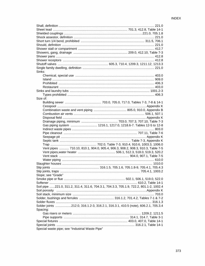
Shall, definition ............................................................................................................ 221.0Sheet Iead .................................................................................... 701.3, 412.8, Table 14-1Shielded couplings .........................................................................................221.0, 705.1.8Shock assestor, definition ........................................................................................... 221.0Short turn 1/4 bend, prohibited ........................................................................ 311.5, 706.1Should, definition ........................................................................................................ 221.0Shower stall or compartment ...................................................................................... 412.7Showers, gang, drainage ............................................................. 209.0, 412.10, Table 7-3Shower pans ............................................................................................................... 412.8Shower receptors ....................................................................................................... 412.8Shutoff valves ......................................................... 605.3, 710.4, 1209.3, 1211.12, 1213.3Single family dwelling, definition ................................................................................. 221.0Sinks:
Chemical, special use ......................................................................................... 403.0Island ................................................................................................................... 909.0Prohibited ............................................................................................................ 406.3Restaurant ........................................................................................................... 403.0
Sinks and laundry tubs .......................................................................................... 1001.2-3Types prohibited .................................................................................................. 406.3
Size of:Building sewer ......................................... 703.0, 705.0, 717.0, Tables 7-3, 7-8 & 14-1Cesspool .................................................................................................... Appendix KCombination waste and vent piping ..................................... 805.0, 910.0, Appendix BCombustion air vents ................................................................................ 506.1, 507.1Disposal field .............................................................................................. Appendix KDrainage piping, minimum ......................................... 703.0, 707.3, 707.10, Table 7-3Gas piping system .............................. 1216.1, 1217.0, 1218.6-7. Tables 12-5 to 12-8Indirect waste pipes ............................................................................................. 803.0Pipe cleanout ................................................................................... 707.11, Table 7-6Seepage pit ................................................................................................ Appendix KSeptic tank ................................................................................ Table 7-3, Appendix KTrap .................................................... 702.0, Table 7-3, 910.4, 910.6, 1003.3, 1006.0Vent pipes ........... 710.10, 810.1, 904.0, 905.4, 906.3, 908.2, 908.3, 910.3, Table 7-5Vent pipes,water heater .......................................... 506.1, 512.3, 518.0, 519.3, 520.2Vent stack ............................................................................... 904.0, 907.1, Table 7-5Water piping ........................................................................................................ 610.0
Slaughter houses ...................................................................................................... 1010.0Slip joints ...................................................... 316.1.5, 705.1.6, 705.1.8-9, 705.4.1, 705.4.3Slip joints, traps .......................................................................................... 705.4.1, 1003.2Slope; see “Grade” Smoke pipe or flue ..................................................................... 502.1, 506.1, 519.0, 522.0Softener ................................................................................................... 610.2, Table 14-1Soil pipe ......221.0, 311.2, 311.4, 311.6, 704.3.1, 704.3.3, 705.1.9, 722.2, 801.1-2, 1002.4Soil porosity ......................................................................................................Appendix KSoil stack, minimum size ............................................................................................ 703.0Solder, bushings and ferrules ....................................... 316.1.2, 701.4.2, Tables 7-1 & 7-2Solder fluxes ............................................................................................................ 316.1.3Solder joints ..................212.0, 316.1.2-3, 316.2.1, 316.3.1, 410.5 (note), 606.2.1, 705.3.4Spacing:
Gas risers or meters ............................................................................. 1209.2, 1211.5Pipe supports .......................................................................... 314.1, 314.7, Table 3-1
Special fixtures ............................................................................. 403.0, 407.0, Table 14-1Special joints ........................................................................................ 316.2.1, Table 14-1Special waste pipe; see “Industrial Waste Pipe”
373
INDEX
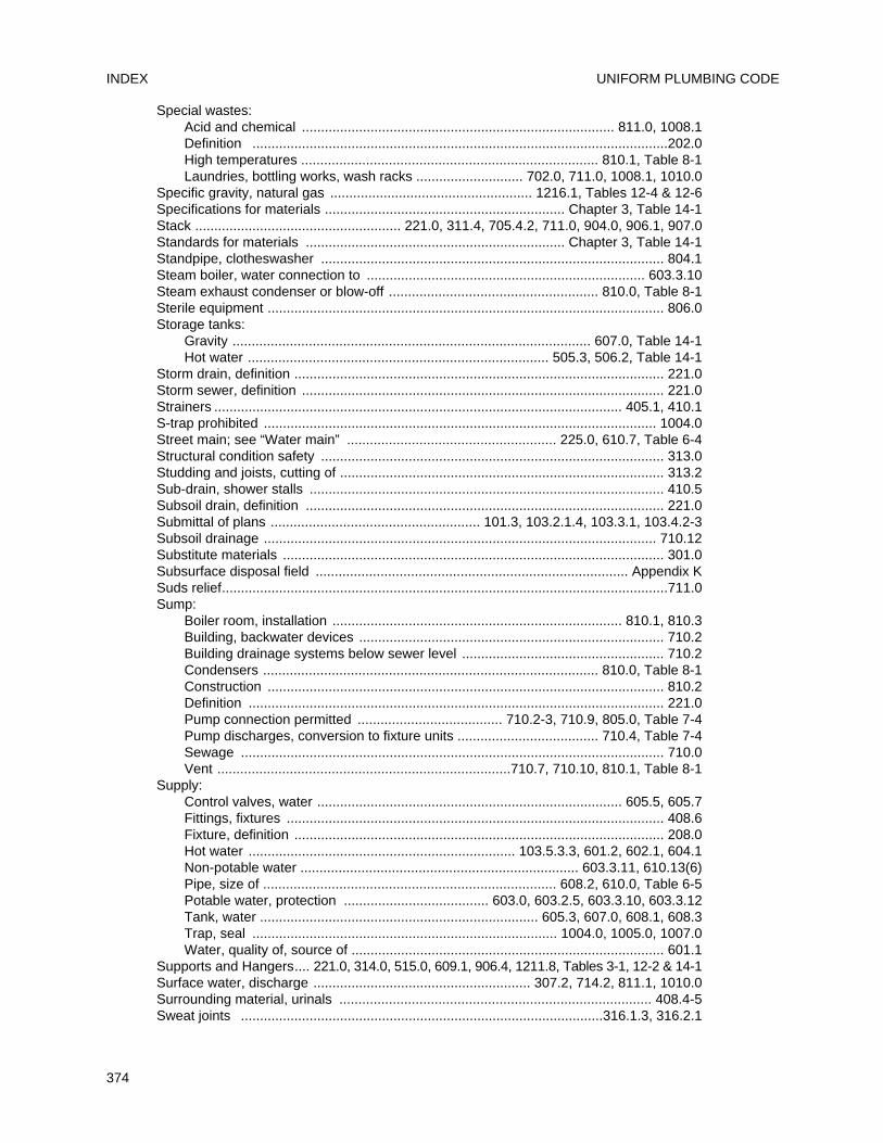
Special wastes:Acid and chemical .................................................................................. 811.0, 1008.1Definition .............................................................................................................202.0High temperatures .............................................................................. 810.1, Table 8-1Laundries, bottling works, wash racks ............................ 702.0, 711.0, 1008.1, 1010.0
Specific gravity, natural gas ..................................................... 1216.1, Tables 12-4 & 12-6Specifications for materials ............................................................... Chapter 3, Table 14-1Stack ...................................................... 221.0, 311.4, 705.4.2, 711.0, 904.0, 906.1, 907.0Standards for materials .................................................................... Chapter 3, Table 14-1Standpipe, clotheswasher .......................................................................................... 804.1Steam boiler, water connection to ......................................................................... 603.3.10Steam exhaust condenser or blow-off ....................................................... 810.0, Table 8-1Sterile equipment ........................................................................................................ 806.0Storage tanks:
Gravity .............................................................................................. 607.0, Table 14-1Hot water ............................................................................... 505.3, 506.2, Table 14-1
Storm drain, definition ................................................................................................. 221.0Storm sewer, definition ............................................................................................... 221.0Strainers ........................................................................................................... 405.1, 410.1S-trap prohibited ....................................................................................................... 1004.0Street main; see “Water main” ....................................................... 225.0, 610.7, Table 6-4Structural condition safety .......................................................................................... 313.0Studding and joists, cutting of ..................................................................................... 313.2Sub-drain, shower stalls ............................................................................................. 410.5Subsoil drain, definition .............................................................................................. 221.0Submittal of plans ....................................................... 101.3, 103.2.1.4, 103.3.1, 103.4.2-3Subsoil drainage ....................................................................................................... 710.12Substitute materials .................................................................................................... 301.0Subsurface disposal field .................................................................................. Appendix KSuds relief.....................................................................................................................711.0Sump:
Boiler room, installation ............................................................................ 810.1, 810.3Building, backwater devices ................................................................................ 710.2Building drainage systems below sewer level ..................................................... 710.2Condensers ........................................................................................ 810.0, Table 8-1Construction ........................................................................................................ 810.2Definition ............................................................................................................. 221.0Pump connection permitted ...................................... 710.2-3, 710.9, 805.0, Table 7-4Pump discharges, conversion to fixture units ..................................... 710.4, Table 7-4Sewage ............................................................................................................... 710.0Vent .............................................................................710.7, 710.10, 810.1, Table 8-1
Supply:Control valves, water ................................................................................ 605.5, 605.7Fittings, fixtures ................................................................................................... 408.6Fixture, definition ................................................................................................. 208.0Hot water ...................................................................... 103.5.3.3, 601.2, 602.1, 604.1Non-potable water ......................................................................... 603.3.11, 610.13(6)Pipe, size of ............................................................................. 608.2, 610.0, Table 6-5Potable water, protection ...................................... 603.0, 603.2.5, 603.3.10, 603.3.12Tank, water ......................................................................... 605.3, 607.0, 608.1, 608.3Trap, seal ................................................................................ 1004.0, 1005.0, 1007.0Water, quality of, source of .................................................................................. 601.1
Supports and Hangers.... 221.0, 314.0, 515.0, 609.1, 906.4, 1211.8, Tables 3-1, 12-2 & 14-1Surface water, discharge ......................................................... 307.2, 714.2, 811.1, 1010.0Surrounding material, urinals .................................................................................. 408.4-5Sweat joints ...............................................................................................316.1.3, 316.2.1
UNIFORM PLUMBING CODEINDEX
374
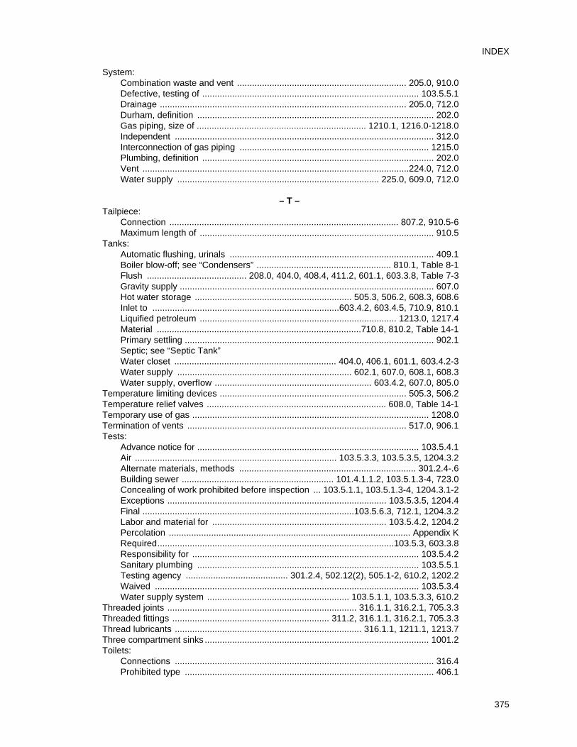
System:Combination waste and vent .................................................................... 205.0, 910.0Defective, testing of ....................................................................................... 103.5.5.1Drainage ................................................................................................... 205.0, 712.0Durham, definition ............................................................................................... 202.0Gas piping, size of .................................................................... 1210.1, 1216.0-1218.0Independent ........................................................................................................ 312.0Interconnection of gas piping ............................................................................ 1215.0Plumbing, definition ............................................................................................. 202.0Vent ...........................................................................................................224.0, 712.0Water supply ................................................................................. 225.0, 609.0, 712.0
– T –Tailpiece:
Connection ............................................................................................ 807.2, 910.5-6Maximum length of .............................................................................................. 910.5
Tanks:Automatic flushing, urinals .................................................................................. 409.1Boiler blow-off; see “Condensers” ...................................................... 810.1, Table 8-1Flush ........................................ 208.0, 404.0, 408.4, 411.2, 601.1, 603.3.8, Table 7-3Gravity supply ...................................................................................................... 607.0Hot water storage ............................................................... 505.3, 506.2, 608.3, 608.6Inlet to ...........................................................................603.4.2, 603.4.5, 710.9, 810.1Liquified petroleum ............................................................................... 1213.0, 1217.4Material ..................................................................................710.8, 810.2, Table 14-1Primary settling .................................................................................................... 902.1Septic; see “Septic Tank”Water closet ................................................................. 404.0, 406.1, 601.1, 603.4.2-3Water supply ...................................................................... 602.1, 607.0, 608.1, 608.3Water supply, overfIow ............................................................... 603.4.2, 607.0, 805.0
Temperature limiting devices ........................................................................... 505.3, 506.2Temperature relief valves ........................................................................ 608.0, Table 14-1Temporary use of gas ............................................................................................... 1208.0Termination of vents ........................................................................................ 517.0, 906.1Tests:
Advance notice for ......................................................................................... 103.5.4.1Air ................................................................................. 103.5.3.3, 103.5.3.5, 1204.3.2Alternate materials, methods ....................................................................... 301.2.4-.6Building sewer ............................................................. 101.4.1.1.2, 103.5.1.3-4, 723.0Concealing of work prohibited before inspection ... 103.5.1.1, 103.5.1.3-4, 1204.3.1-2Exceptions ........................................................................................ 103.5.3.5, 1204.4Final .....................................................................................103.5.6.3, 712.1, 1204.3.2Labor and material for ...................................................................... 103.5.4.2, 1204.2Percolation ................................................................................................. Appendix KRequired...............................................................................................103.5.3, 603.3.8Responsibility for ........................................................................................... 103.5.4.2Sanitary pIumbing ......................................................................................... 103.5.5.1Testing agency ......................................... 301.2.4, 502.12(2), 505.1-2, 610.2, 1202.2Waived .......................................................................................................... 103.5.3.4Water supply system ......................................................... 103.5.1.1, 103.5.3.3, 610.2
Threaded joints ............................................................................ 316.1.1, 316.2.1, 705.3.3Threaded fittings ............................................................... 311.2, 316.1.1, 316.2.1, 705.3.3Thread lubricants ........................................................................... 316.1.1, 1211.1, 1213.7Three compartment sinks .......................................................................................... 1001.2Toilets:
Connections ........................................................................................................ 316.4Prohibited type .................................................................................................... 406.1
375
INDEX
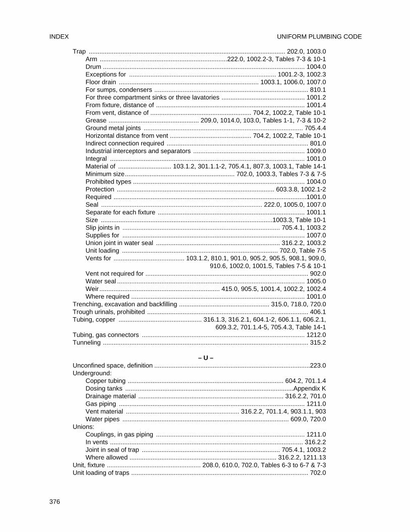
Trap ............................................................................................................... 202.0, 1003.0Arm ........................................................................222.0, 1002.2-3, Tables 7-3 & 10-1Drum .................................................................................................................. 1004.0Exceptions for ................................................................................... 1001.2-3, 1002.3Floor drain ............................................................................... 1003.1, 1006.0, 1007.0For sumps, condensers ....................................................................................... 810.1For three compartment sinks or three lavatories ............................................... 1001.2From fixture, distance of .................................................................................... 1001.4From vent, distance of ......................................................... 704.2, 1002.2, Table 10-1Grease ................................................... 209.0, 1014.0, 103.0, Tables 1-1, 7-3 & 10-2Ground metal joints .......................................................................................... 705.4.4Horizontal distance from vent .............................................. 704.2, 1002.2, Table 10-1Indirect connection required ................................................................................ 801.0Industrial interceptors and separators ............................................................... 1009.0Integral .............................................................................................................. 1001.0Material of .............................. 103.1.2, 301.1.1-2, 705.4.1, 807.3, 1003.1, Table 14-1Minimum size.............................................................. 702.0, 1003.3, Tables 7-3 & 7-5Prohibited types ................................................................................................. 1004.0Protection ......................................................................................... 603.3.8, 1002.1-2Required .............................................................................................................1001.0Seal ........................................................................................... 222.0, 1005.0, 1007.0Separate for each fixture ................................................................................... 1001.1Size .................................................................................................1003.3, Table 10-1Slip joints in ......................................................................................... 705.4.1, 1003.2Supplies for ....................................................................................................... 1007.0Union joint in water seal ...................................................................... 316.2.2, 1003.2Unit loading ........................................................................................ 702.0, Table 7-5Vents for ........................................ 103.1.2, 810.1, 901.0, 905.2, 905.5, 908.1, 909.0,
910.6, 1002.0, 1001.5, Tables 7-5 & 10-1Vent not required for ............................................................................................ 902.0Water seal .......................................................................................................... 1005.0Weir .................................................................... 415.0, 905.5, 1001.4, 1002.2, 1002.4Where required .................................................................................................. 1001.0
Trenching, excavation and backfilling ................................................... 315.0, 718.0, 720.0Trough urinals, prohibited ........................................................................................... 406.1Tubing, copper ............................................... 316.1.3, 316.2.1, 604.1-2, 606.1.1, 606.2.1,
609.3.2, 701.1.4-5, 705.4.3, Table 14-1Tubing, gas connectors ............................................................................................ 1212.0Tunneling .................................................................................................................... 315.2
– U –Unconfined space, definition ........................................................................................223.0Underground:
Copper tubing ........................................................................................ 604.2, 701.1.4Dosing tanks ...............................................................................................Appendix KDrainage material .................................................................................. 316.2.2, 701.0Gas piping ......................................................................................................... 1211.0Vent material ................................................................ 316.2.2, 701.1.4, 903.1.1, 903Water pipes .............................................................................................. 609.0, 720.0
Unions:Couplings, in gas piping .................................................................................... 1211.0In vents ............................................................................................................. 316.2.2Joint in seal of trap .............................................................................. 705.4.1, 1003.2Where allowed ................................................................................... 316.2.2, 1211.13
Unit, fixture ..................................................... 208.0, 610.0, 702.0, Tables 6-3 to 6-7 & 7-3Unit loading of traps .................................................................................................... 702.0
UNIFORM PLUMBING CODEINDEX
376
Unlawful connections .................................................................................................. 602.0Unsanitary, definition .................................................................................................. 223.0Unusually tight construction .............................................................502.7, 507.2, Table 5-1Urinals ................................................ 316.3.1, 402.2, 404.0, 406.1, 408.6, 410.0, 601.1,
707.4(1), 1003.1, Tables 7-3 & 7-5Use of alternate material ............................................................................................ 301.2Use, private, definition ................................................................................................ 218.0
– V –Vacuum breaker ............................... 224.0, 409.0, 603.0-603.3.15, Tables 1-1, 6-1 7 14-1Vacuum relief vent, definition ..................................................................................... 224.0Validity of code ............................................................................................. 103.7.1, 103.8Valves ........................................................................................ 311.7, 605.0, Table 14-1
Backwater ............................................................................................................ 710.0Check ........................................................................................... 603.1.3-5, Table 6-2Spring loaded .................................................................................................. 1211.14Flush , definition ................................................................................................... 208.0Flushometer ........................................... 411.2-3, 603.3.1, 603.3.8, 610.10, Table 6-7For drainage ..................................................................................... 710.4, Table 14-1For water ................................................................................................ 412.10, 605.0Hose outlet protection ...................................................................................... 603.3.8Required .......................................................................................... 605.0, 1211.14-20Temperature and pressure relief ...................................................... 608.2, Table 14-1Water control ..................................................................................................... 410.10
Vaults, for gas meters ............................................................................................... 1209.5Vent or vent pipe:
Below trap weir ....................................................................................... 905.5, 1002.4Branch, definition ................................................................................................. 204.0Changes in direction of ........................................................................................ 903.4Chemical ................................................................................................811.2, 811.5-6Combination waste system design ...................................... 205.0, 910.0, Appendix BCommon vent .................................................................. 205.0, 519.0, 523.3.1, 908.3Connections ................................................................. 311.2, 805.0, 905.1, Table 8-1Connectors ........................................................... 513.2, 514.0, 515.0, 516.4-5, 524.3Continuous, definition .......................................................................................... 205.0Distance of trap from ...................................................................... 1002.2, Table 10-1Double fitting for ....................................................................................... 704.2, 905.0Drain and waste .......................................................................... Table 7-3, Chapter 7Fittings ........................................................................................................... Table 7-5Fixtures, back to back .............................................................................. 704.2, 905.6Flagpoling, prohibited .......................................................................................... 906.3Flashing for ......................................................................... 313.8, 517.1, 906.1, 906.5Grade of ................................................................................................... 905.1, 905.3Height above fixture ................................................................................. 905.3, 909.0Height above ground ................................................................................ 517.5, 906.4Horizontal .......................................................... 516.1, 516.3, Table 7-5, 904.2, 905.3Indirect waste ....................................................... 801.1-2, 803.0, 805.0, 810.1, 902.0Individual, definition ............................................................................................. 202.0Interceptors ............................................................................................ 902.1, 1008.4lsland sinks and fixtures ...................................................................................... 909.0Length of ............................................................................................ Table 7-5, 904.0Material for .................................................................................... 514.1, 811.2, 903.0Method of installation .................. 311.5, 501.0, 512.5-6, 520.1, 523.3, 903.1.2, 906.4Minimum size in each building ........................................................... Table 7-5, 904.0Not required .............................................................................................. 803.0, 902.0Not to be used as soil or waste pipe ..................................................... 311.4, 801.1-2
377
INDEX
Opening location .................................................................................... 905.5, 1002.4Parallel, connection ............................................................................................. 907.1Pipe, grade and connection ...................................................................... 905.1, 905.3Prohibited location of .......................................................................... 903.1.1-2, 903.3Receptors ......................................................................................... 811.2, Table 14-1Relief ................................................................................ 222.0, 805.0, 907.0, 1008.4Required ........................................................................................ 710.0, 901.0, 904.1Required separately on every trap ........................................... 901.0, 902.1, 1002.1-2Sizing ..................................................... Table 7-3, 710.0, 904.0, 905.4, 908.0, 910.4Special ............................................................................................... Chapter 8, 909.0Stack .................................................................................. 224.0, 311.4, 906.1, 907.0Steam, exhaust ................................................................................................... 810.0Sump .......................................................................... 710.7, 710.10, 810.1, Table 8-1System, definition ................................................................................................ 202.0Ten stories or more ............................................................................................. 907.1Termination .............................................................................................. 517.0, 906.0Undiminished through roof ....................................................................... 905.4, 907.1Unit loading ................................................................................................... Table 7-5Vertical wet; see “Wet Vent”Wet; see “Wet Vent”Yoke ......................................................................................................... 227.0, 907.0
Vent connector ............................................................ 513.2, 514.0, 515.0, 516.4.5, 524.3Vent manifold, gas ...................................................................... 519.4, 523.3.1, 1218.4(1)Vent or vent flue ......................................................................................................... 502.0Ventilation for gas water heater enclosures .................................................... 506.1, 507.1Vertical pipe: ........................................................ 224.0, 703.0, 704.2, 905.6, 908.2, 910.5
Unit loading length-drainage piping ............................................................... Table 7-5Piping, support of ................................................................................................ 314.0
Vertical to horizontal drainage fittings ............................................... 706.4, 905.2-3, 909.0Vertical wet venting; see “Wet Vent”Violation, notices of .............................................................................................. 103.5.6.1Vitrified clay ................................................................. 701.1-2, 705.3.1, 811.2, Table 14-1
– W –Wall, extension through ................................................................................... 313.1, 514.3Wall-hung fixtures, installation of .................................................... 316.3.3, 408.2, 408.4-6Wall-hung water closets, definition ............................................................................. 225.0Wall, recess or channel in ........................................................................... 313.2, 1211.18Wash racks, auto ........................................................................................... 805.0, 1011.0Waste ................................................................................................................ Chapter 7
Chemical laboratory, photographic ...................................................................... 811.0Cooling water ........................................................................................... 801.0, 808.0Combination ......................................................................... 205.0, 901.0, Appendix BContinuous ........................................................................... 205.0, 405.3-4, Table 7-3Detrimental or harmful ...................................................... 306.1, 307.0, 811.1, 1009.1Food, disposal unit; see “Food waste disposal unit”Indirect ................................................................... 211.0, Table 7-3, Chapter 8, 902.0Industrial ...................... 211.0, 307.0, 811.1, 903.2.3, 1001.3, 1009.0, 1010.0, 1014.0Liquid ............................................. 214.0, 303.0, 304.0, 710.2, 811.1, 1006.0, 1009.1Pipe, definition ................................................................................................... 2018.0
Buildings over ten stories ............................................................................. 907.1For refrigerators ........................................................................... Table 7-3, 801.2Indirect .................................................................................... 211.0, 801.0, 805.0
Accessibility ........................................................................................... 804.1Airbreak ................................................................................................. 801.0Airgap for ...................................................................... 603.3.8, 801.0, 806.0Installation of ....................................... 313.6, Table 4-1, 802.0, 803.0, 810.0
UNIFORM PLUMBING CODEINDEX
378
Material of, inside building ............................................................................ 701.0Number of fixtures allowed on ................................................................ Table 7-5Size of ......................................................................................... Tables 7-3 & 7-5
Pretreatment required ............................................................................ 811.1, 1011.1Receptor, prohibited location ............................................................................... 804.1Special, definition ................................................................................................ 202.0Stack, definition ................................................................................................... 202.0
Water:Additions to existing work ............................................................... 101.5.1, 610.13(2)Building supply ............................................................. 604.1, 609.5, 610.0, Table 6-5Conditioning ....................................................................... 225.0, 603.0, 609.4, 610.2Distributing pipe, definition .................................................................................. 202.0Distribution system ....................................................................................... Chapter 6Filter .................................................................................................................... 610.2Hammer arrestor, definition ..................................................................................225.0Main, definition .................................................................................................... 225.0Non-potable lines .......................................................................... 603.4.11, 610.13(6)Piping:
Grounding ..................................................................................................... 604.8In sewer trench ....................................................................... 315.0, 609.2, 720.0Installation of ....................................... 313.6, 603.3.8, 604.8, 609.0, 610.0, 720.0Material ..................................................................................... 604.0, Table 14-1Sizing ............................................................................... 610.0, Tables 6-4 & 6-5Test ............................................................................................................103.5.3
Potable ...................................................... 218.0, 316.1.3, 501.0, 602.0-603.0, 604.5,604.7, 604.10, 607.0, 608.2, 610.1-2, 610.13(7)
Pressure:Excessive ................................................................................................. 608.2-6Inadequate ................................................................................................... 608.1Loss............................................................................................................... 610.0Regulators and relief valves ...................................................................... 608.2-6
Private supply ..................................................................................... 602.4, Table 6-4Prohibited materials ........................................................................................... 604.10Protection of potable ........................................................................................... 603.0Required ................................................................................................... 601.1, 610.3Service, size ....................................................................................... 610.0, Table 6-5Softener ............................................................................................ 610.2, Table 14-1Supply:
Cross-connectors ............................................................... 601.1, 602.3, 603.4.11Flushometer valves; see “Flushometer valves”To fixtures ........................................................................ 610.0, Tables 6-4 & 6-5System, definition ......................................................................................... 221.0
Supply tank ........................................................................ 603.4.2, 607.0, Table 14-1Temperature limiting device ..................................... 502.13, 505.3, 506.2, Table 14-1Test .......................................................................................................... 103.5, 610.2Unlawful:
Connections ................................................................................................. 602.0Devices ......................................................................................................... 602.3
Valves, control ........................................................................................ 412.10, 605.0Water closets ...................................316.3.1, 401.1, 404.0, 406.1, 408.0, 601.1, 603.3.1-3,
610.3, 910.7, Tables 6-4 & 7-3Water heaters:
Access ...................................................................................................... 510.2, 511.0Approved type required .............................................................. 501.0, 505.1-2, 506.1Clearances .......................................................................................................... 508.0Combustion air for ........................................................ 506.1, 507.0, 510.2, Table 5-1
379
INDEX
Definition ............................................................................................................. 502.0Enclosures ....................................................................... 507.2, 510.2, 511.0, 523.3.5Gas ...... .............................................................................505.0, 514.1, 524.4, 1213.6Oil-burning and other ............................................................ 501.0, 506.0, Table 14-1Pressure relief valve ......................................................................................... 608.3-6Prohibited location .................................................................... 508.0, 509.0, 1213.5-6Protection ...................................................................................... 505.3, 510.3, 501.5Sealed combustion type ................................................................ 502.6, 509.0, 510.2Venting of .................................. 501.0, 502.5-6, 502.8-12, 504.1, 506.1, 512.0-525.0
Waterproofing:Fixture setting ........................................................................................ 316.3.1, 408.0Flashings ....................................................................................... 313.8, 517.1, 906.5Openings .................................................................................................. 313.8, 906.5
Water sealed traps; see “Traps”Water softener ......................................................................................... 610.2, Table 14-1Water test:
Building sewers ................................................................................................... 103.5Plumbing, drainage and vent system ....................................................... 103.5, 712.0
Water treatment device; see “Water Conditioning”Weep holes, sub-drain of shower stalls ...................................................................... 412.8Weight of flashing, lead .............................................................................................. 701.3Weights and quality of materials .................... Chapter 3, 604.0, 906.6, 1210.5, Table 14-1Welded lead joints ...................................................................................... 705.1.3, 1211.2Welder, pipe, definition ............................................................................................... 225.0Welding or brazing joints ........................................... 316.1.7, 705.1.3, 1211.2, Table 14-1Well, distance from sewage disposal ........................................................ 721.1, Table 7-7Wet vent ..... ............................................................................225.0, 316.2.2, 908.0, 910.6Whirlpool bathtub, definition ....................................................................................... 225.0Window, termination of vents from .................................................................. 517.5, 906.2Wiped joints ................................................................................................316.1.2, 705.3.4Wooden sinks and laundry trays ................................................................................ 406.2Work, concealed .......................... 103.1.2, 103.5.1-2, 504.2, 1204.3.1-2, 1211.3, 1211.12Work, existing ............................................................................................... 101.4-5, 207.0Work, exposed, where required ... 103.1.2, 103.5.1-2, 504.2, 1204.3.1-2, 1211.3, 1211.13Working space ............................................................................................................ 511.0Workmanship ...................................................................................... 310.0, 609.1, 1203.0Wrapping of pipe ................................................. 313.0, 609.3.1, 1211.5, 1211.10, 1218.8Wrought iron (galvanized) ..................................................... 316.1.2, 604.1, 605.2, 701.1,
705.3.3-4, 707.1, 903.1, 1210.1, Table 14-1Wye connections ................................... 405.4, 706.0, 707.6-7, 710.4, 719.4, 907.2, 909.0
– X –X-ray darkrooms ......................................................................................................... 811.8
– Y –Yard piping, gas .............................................................................. 1202.0, 1211.0, 1217.0
– Z –Zinc alloy die cast components .................................................................................. 403.1
UNIFORM PLUMBING CODEINDEX
380