unified facilities criteria (ufc) - san francisco … · ufc 3-570-06 january 31 2003 unified...
TRANSCRIPT
UFC 3-570-06 JANUARY 31 2003
UNIFIED FACILITIES CRITERIA (UFC)
OPERATION AND MAINTENANCE: CATHODIC PROTECTION SYSTEMS
APPROVED FOR PUBLIC RELEASE; DISTRIBUTION UNLIMITED
UFC 3-570-06 JANUARY 31 2003
UNIFIED FACILITIES CRITERIA (UFC)
OPERATION AND MAINTENANCE: CATHODIC PROTECTION Any copyrighted material included in this UFC is identified at its point of use. Use of the copyrighted material apart from this UFC must have the permission of the copyright holder. U.S. ARMY CORPS OF ENGINEERS NAVAL FACILITIES ENGINEERING COMMAND AIR FORCE CIVIL ENGINEER SUPPORT AGENCY (Preparing Activity) Record of Changes (changes are indicated by \1\ ... /1/) Change No. Date Location
_____________ This UFC supersedes MO-324, Dated April 1992.

UFC 3-570-06 JANUARY 31 2003
FOREWORD The Unified Facilities Criteria (UFC) system is prescribed by MIL-STD 3007 and provides planning, design, construction, sustainment, restoration, and modernization criteria, and applies to the Military Departments, the Defense Agencies, and the DoD Field Activities in accordance with USD(AT&L) Memorandum dated 29 May 2002. UFC will be used for all DoD projects and work for other customers where appropriate. All construction outside of the United States is also governed by Status of forces Agreements (SOFA), Host Nation Funded Construction Agreements (HNFA), and in some instances, Bilateral Infrastructure Agreements (BIA.) Therefore, the acquisition team must ensure compliance with the more stringent of the UFC, the SOFA, the HNFA, and the BIA, as applicable. UFC are living documents and will be periodically reviewed, updated, and made available to users as part of the Services’ responsibility for providing technical criteria for military construction. Headquarters, U.S. Army Corps of Engineers (HQUSACE), Naval Facilities Engineering Command (NAVFAC), and Air Force Civil Engineer Support Agency (AFCESA) are responsible for administration of the UFC system. Defense agencies should contact the preparing service for document interpretation and improvements. Technical content of UFC is the responsibility of the cognizant DoD working group. Recommended changes with supporting rationale should be sent to the respective service proponent office by the following electronic form: Criteria Change Request (CCR). The form is also accessible from the Internet sites listed below. UFC are effective upon issuance and are distributed only in electronic media from the following source: • Whole Building Design Guide web site http://dod.wbdg.org/. Hard copies of UFC printed from electronic media should be checked against the current electronic version prior to use to ensure that they are current. AUTHORIZED BY: ______________________________________ DONALD L. BASHAM, P.E. Chief, Engineering and Construction U.S. Army Corps of Engineers
______________________________________DR. JAMES W WRIGHT, P.E. Chief Engineer Naval Facilities Engineering Command
______________________________________ KATHLEEN I. FERGUSON, P.E. The Deputy Civil Engineer DCS/Installations & Logistics Department of the Air Force
______________________________________Dr. GET W. MOY, P.E. Director, Installations Requirements and Management Office of the Deputy Under Secretary of Defense (Installations and Environment)

UFC 3-570-06 JANUARY 31 2003
i
CONTENTS
Page CHAPTER 1 INTRODUCTION Paragraph 1-1 SCOPE.............................................................................................. 1-1
1-2 CATHODIC PROTECTION SYSTEMS............................................. 1-1 1-2.1 Application ........................................................................................ 1-1 1-2.2 Benefits ............................................................................................. 1-2 1-3 CP SYSTEM MAINTENANCE .......................................................... 1-2 1-4 CP PROGRAM ELEMENTS ............................................................. 1-2
CHAPTER 2 PRINCIPLES OF OPERATION Paragraph 2-1 THE CORROSION PROCESS ......................................................... 2-1
2-1.1 Corrosion Cell ................................................................................... 2-1 2-2 TYPES OF CORROSION ................................................................. 2-5 2-2.1 General Corrosion............................................................................. 2-5 2-2.2 Concentration Cell Corrosion............................................................ 2-6 2-2.3 Galvanic Corrosion............................................................................ 2-10 2-2.4 Stray Current Corrosion .................................................................... 2-14 2-3 RATE OF CORROSION ................................................................... 2-19 2-3.1 Electrical Effects on the Rate of Corrosion ....................................... 2-19 2-3.2 Chemical Effects on the Rate of Corrosion....................................... 2-20 2-3.3 Area Relationships............................................................................ 2-22 2-4 GALVANIC SERIES.......................................................................... 2-22 2-5 INTRODUCTION TO CATHODIC PROTECTION ............................ 2-25 2-6 GALVANIC CATHODIC PROTECTION............................................ 2-27 2-6.1 Galvanic Anode Types...................................................................... 2-30 2-6.2 Advantages and Disadvantages of Galvanic Anode Systems .......... 2-37 2-6.3 Installation of Galvanic Anodes......................................................... 2-37 2-6.4 Galvanic Anode Connection to Structure .......................................... 2-38 2-6.5 Galvanic Test Stations ...................................................................... 2-39 2-7 IMPRESSED CURRENT CATHODIC PROTECTION ...................... 2-41 2-7.1 Impressed Current Rectifiers ............................................................ 2-42 2-7.2 Impressed Current Anode Materials ................................................. 2-44 2-7.3 Types of Impressed Current Anode Beds ......................................... 2-52 2-7.4 Advantages and Disadvantages of Impressed Current Anode Systems................................................................................. 2-56 2-7.5 Impressed Current Test Stations ...................................................... 2-56
CHAPTER 3 REQUIREMENTS Paragraph 3-1 APPLICABLE STANDARDS ............................................................. 3-1
3-2 DESIGN AND CONSTRUCTION CONSIDERATIONS..................... 3-1 3-2.1 Ductile Iron Pipe................................................................................ 3-1

UFC 3-570-06 JANUARY 31 2003
ii
3-2.2 Soil Resistives................................................................................... 3-1 3-2.3 Joint Bonds ....................................................................................... 3-1 3-2.4 Thermite Welds and Exposed Copper Wire...................................... 3-1 3-2.5 Copper .............................................................................................. 3-1 3-2.6 Metallic Ferrous Pipe ........................................................................ 3-2 3-2.7 Lightning and Fault Current .............................................................. 3-2 3-3 SYSTEMS REQUIRING CATHODIC PROTECTION ....................... 3-2 3-3.1 New Piping Systems ......................................................................... 3-3 3-3.2 Existing Piping Systems.................................................................... 3-3 3-4 SYSTEMS NOT REQUIRING CATHODIC PROTECTION (EXISTING) .............................................................. 3-3 3-5 FIELD TESTS ................................................................................... 3-3 3-6 DEVIATIONS .................................................................................... 3-3
CHAPTER 4 SCHEDULED PREVENTIVE MAINTENANCE Paragraph 4-1 INTRODUCTION............................................................................... 4-1
4-2 CLOSE-INTERVAL CORROSION SURVEY .................................... 4-1 4-2.1 Maintenance Intervals ....................................................................... 4-1 4-2.2 Minimum Requirements .................................................................... 4-1 4-3 CORROSION SURVEY .................................................................... 4-4 4-3.1 Maintenance Interval......................................................................... 4-4 4-3.2 Minimum Requirements .................................................................... 4-4 4-4 WATER TANK CALIBRATION.......................................................... 4-8 4-4.1 Maintenance Intervals ....................................................................... 4-8 4-4.2 Minimum Requirements .................................................................... 4-8 4-5 RECTIFIER OPERATIONAL INSPECTION...................................... 4-10 4-5.1 Maintenance Intervals ....................................................................... 4-10 4-5.2 Minimum Requirements .................................................................... 4-10 4-6 IMPRESSED CURRENT ANODE BED ............................................ 4-11 4-7 IMPRESSED CURRENT SYSTEM CHECK ..................................... 4-11 4-7.1 Maintenance Intervals ....................................................................... 4-12 4-7.2 Minimum Requirements .................................................................... 4-12 4-8 GALVANIC ANODE CHECK............................................................. 4-12 4-8.1 Procedure ......................................................................................... 4-13 4-9 RESISTANCE BOND CHECK .......................................................... 4-13 4-9.1 Maintenance Interval......................................................................... 4-13 4-9.2 Minimum Requirements .................................................................... 4-13 4-10 LEAK SURVEY ................................................................................. 4-14 4-10.1 Maintenance Interval ........................................................................ 4-14 4-10.2 Minimum Requirements .................................................................... 4-14 4-10.3 Galvanic Anode Systems.................................................................. 4-15 4-11 RECORD KEEPING REQUIREMENTS............................................ 4-15

UFC 3-570-06 JANUARY 31 2003
iii
CHAPTER 5 UNSCHEDULED MAINTENANCE REQUIREMENTS Paragraph 5-1 INTRODUCTION............................................................................... 5-1
5-1.1 Troubleshooting ................................................................................ 5-1 5-1.2 Procedures........................................................................................ 5-1 5-2 TROUBLESHOOTING INPRESSED CURRENT SYSTEMS............ 5-1 5-2.1 DC Voltage........................................................................................ 5-1 5-2.2 DC Current ........................................................................................ 5-4 5-2.3 Anode Lead Wires ............................................................................ 5-7 5-2.4 Structure Lead .................................................................................. 5-7 5-2.5 AC Voltage to Stacks ........................................................................ 5-7 5-2.6 Fuses ................................................................................................ 5-8 5-2.7 Diodes............................................................................................... 5-9 5-2.8 Anode Bed ........................................................................................ 5-9 5-2.9 Rectifier Taps.................................................................................... 5-10 5-2.10 Rectifier input Voltage....................................................................... 5-11 5-3 IMPRESSED CURRENT SYSTEM COMMON PROBLEMS ............ 5-11 5-4 TROUBLESHOOTING GALVANIC (SACRIFICIAL) CATHODIC
PROTECTION SYSTEMS ................................................................ 5-13 5-4.1 Common Problems ........................................................................... 5-13 5-4.2 Lead Wires........................................................................................ 5-13 5-4.3 Anode Consumption.......................................................................... 5-13 5-4.4 Improper Use .................................................................................... 5-13 5-5 INTERFERENCE TESTING.............................................................. 5-13 5-6 INTERFERENCE CORROSION CONTROL..................................... 5-14 5-6.1 Correcting Interference ..................................................................... 5-14 5-6.2 Direct Bonding .................................................................................. 5-14 5-6.3 Bonding............................................................................................. 5-15 5-6.4 Installing a Sacrificial Anode ............................................................. 5-15 5-6.5 Additional Coating............................................................................. 5-17 5-6.6 Installation of Nonmetallic Sections or Isolations.............................. 5-18 5-6.7 Application of a Small Impressed Current System............................ 5-18 5-6.8 Combination of Techniques .............................................................. 5-18
CHAPTER 6 INSPECTION PROCEDURES AND CRITERIA Paragraph 6-1 INTRODUCTION............................................................................... 6-1
6-1.1 Methods ............................................................................................ 6-1 6-2 APPLICABILITY................................................................................ 6-1 6-3 CRITERIA ......................................................................................... 6-2 6-3.1 Steel and Cast Iron Piping ................................................................ 6-2 6-3.2 Special Conditions ............................................................................ 6-3 6-3.3 Aluminum Piping ............................................................................... 6-4 6-3.4 Copper Piping ................................................................................... 6-4 6-3.5 Dissimilar Metal Piping...................................................................... 6-4

UFC 3-570-06 JANUARY 31 2003
iv
6-4 OTHER CONSIDERATIONS ............................................................ 6-4 6-4.1 Determining Voltage Drops............................................................... 6-5 6-4.2 Sound Engineering Practices............................................................ 6-5 6-4.3 In-Line Inspection of Pipes................................................................ 6-5 6-4.4 Stray Currents and Stray Electrical Gradients .................................. 6-5 6-5 ALTERNATIVE REFERENCE ELECTRODES ................................. 6-5 6-5.1 Alternative to Saturated Copper / Copper Sulfate ............................ 6-5 6-5.2 Alternative Metallic Material or Structure .......................................... 6-5
CHAPTER 7 TESTING Paragraph 7-1 POTENTIAL MEASUREMENT ......................................................... 7-1
7-2 SOURCES OF ERROR .................................................................... 7-1 7-2.1 Accuracy of the Reference Electrode................................................ 7-1 7-2.2 IR Drop Error..................................................................................... 7-3 7-2.3 Anode Gradient Error ........................................................................ 7-4 7-2.4 Contact Resistance Error .................................................................. 7-5 7-2.5 Mixed Potential Error......................................................................... 7-6 7-3 PRACTICAL MEASUREMENT OF CATHODIC PROTECTION
POTENTIALS.................................................................................... 7-7 7-3.1 Test Criteria Selection....................................................................... 7-7 7-3.2 Test Methods for the -0.85 ON Criterion ........................................... 7-9 7-3.3 Test Methods for the -0.85 Instant-OFF Criterion ............................. 7-11 7-3.4 Test Methods for the 100mV Polarization Criterion .......................... 7-11 7-3.5 Instant-OFF Test Methods ................................................................ 7-11 7-3.6 Types of Interrupters ......................................................................... 7-12 7-3.7 Specific Methods for Various Instant-OFF Potential Measurement
Techniques ....................................................................................... 7-13 7-4 STRUCTURE-TO-SOIL POTENTIAL LIMITS................................... 7-17 7-4.1 Excessive Cathodic Protection Current............................................. 7-17 7-4.2 Water Storage Tanks ........................................................................ 7-18 7-4.3 Underground Structures.................................................................... 7-18 7-4.4 Uncoated Structures ......................................................................... 7-19 7-5 CELL-TO-CELL POTENTIAL TESTING PROCEDURES................. 7-19 7-5.1 Performing Test................................................................................. 7-19 7-5.2 Accuracy ........................................................................................... 7-20 7-6 RECTIFIER EFFICIENCY TESTING PROCEDURES...................... 7-21 7-6.1 Determining Efficiency ...................................................................... 7-21 7-6.2 Alternate Procedure .......................................................................... 7-21 7-6.3 Expected Efficiency........................................................................... 7-22 7-7 DIELECTRIC TESTING PROCEDURES.......................................... 7-22 7-7.1 Testing for a Shorted Dielectric......................................................... 7-23 7-7.2 Using a Radio Frequency Tester ...................................................... 7-25 7-7.3 Using a Pipe Locator......................................................................... 7-25 7-7.4 Using a Temporary Local Cathodic Protection System..................... 7-27 7-8 CASING TESTS................................................................................ 7-27

UFC 3-570-06 JANUARY 31 2003
v
7-8.1 Testing a Casing with Cathodic Protection on the Carrier Pipeline... 7-28 7-8.2 Testing a Casing without Cathodic Protection on the Carrier Pipeline ................................................................................. 7-30 7-9 TESTING FOR A SHORT BETWEEN TWO STRUCTURES ........... 7-30 7-9.1 Testing for a Short Between Two Structures with Cathodic Protection on One Structure .............................................. 7-31 7-9.2 Testing for a Short Between Two Structures with Cathodic Protection on Both Structures............................................ 7-33 7-9.3 Testing for a Short Between Two Structures without Cathodic Protection on Either Structure............................................ 7-36 7-10 CURRENT REQUIREMENT TESTING PROCEDURES .................. 7-38 7-10.1 Temporary Local Cathodic Protection Systems ................................ 7-38 7-10.2 Existing Metallic Structures............................................................... 7-39 7-10.3 Temporary Anodes............................................................................ 7-39 7-10.4 Installation of Temporary Anode System .......................................... 7-39 7-10.5 Connections ...................................................................................... 7-40 7-10.6 Before Applying Power...................................................................... 7-40 7-10.7 Applying Power ................................................................................. 7-40 7-10.8 Sufficient Current .............................................................................. 7-40 7-10.9 Calculating Current Requirements .................................................... 7-40 7-10.10 More than One Anode Bed ............................................................... 7-41 7-10.11 Completion of Testing ....................................................................... 7-41 7-11 ELECTROLYTE RESISTIVITY MEASUREMENT ............................ 7-41 7-11.1 Four-Pin Method ............................................................................... 7-42 7-11.2 Two-Pin Method................................................................................ 7-43 7-11.3 Other Methods (Soil Rod, Soil Box) .................................................. 7-44 7-12 pH TESTING PROCEDURES........................................................... 7-45 7-12.1 Antimony Electrode Test Method...................................................... 7-46 7-12.2 Chemical Test Method ...................................................................... 7-48 7-13 CALIBRATION OF IR DROP TEST SPAN ....................................... 7-48 7-13.1 Measurement Circuits ....................................................................... 7-50 7-13.2 Direction of Current Flow .................................................................. 7-51 7-13.3 Resistance of the Pipeline ................................................................ 7-52 7-13.4 Multi-Combination Meter ................................................................... 7-54 7-14 INTERFERENCE TESTING PROCEDURES ................................... 7-55 7-14.1 Interference from Cathodic Protection Rectifiers .............................. 7-55 7-14.2 Interference from Variable (Fluctuating) Sources ............................. 7-59
APPENDIX A AIR FORCE ONLY................................................................... A-1 APPENDIX B NAVY ONLY............................................................................. B-1 APPENDIX C ARMY ONLY.................................................................................... C-1 APPENDIX D GENERAL REFERENCES ............................................................ D-1

UFC 3-570-06 JANUARY 31 2003
vi
FIGURES Figure Title 2-1 The Corrosion Cell..................................................................................... 2-3 2-2 Corrosion Cell, The Dry Cell battery .......................................................... 2-3 2-3 Concentration Cell Caused by Different Environments.............................. 2-7 2-4 Concentration Cell Caused by Different Concentrations of Oxygen .......... 2-8 2-5 Concentration Cell Caused by Different Concentrations of Water ............. 2-8 2-6 Concentration Cell Caused by Non-Homogenous Soil .............................. 2-9 2-7 Concentration Cell Caused by Concrete and Soil Electrolytes ..................2-10 2-8 Galvanic Corrosion Cell Caused by Different Metals.................................2-11 2-9 Galvanic Corrosion Cell Caused by Old and New Steel ............................2-12 2-10 Galvanic Corrosion Cell Caused by Marred and Scratched Surfaces .......2-13 2-11 Combination of Many Different Corrosion Cells at Work ...........................2-14 2-12 Stray Current Corrosion Cell Caused by External Anode and Cathode.....2-15 2-13 Stray Current Corrosion Cell Caused by a DC Transit System .................2-17 2-14 Stray Current Corrosion Cell Caused by an HVDC Transmission System 2-18 2-15 Stray Current Corrosion Cell Caused by a DC Welding Operation............2-18 2-16 Stray Current Corrosion Cell Caused by a Cathodic Protection System ...2-19 2-17 Effect of Electrolyte pH on the Rate of Corrosion ......................................2-22 2-18 Direct Attachment Galvanic (Sacrificial) Cathodic Protection System .......2-29 2-19 Distributed Sacrificial (Galvanic) Cathodic Protection System...................2-30 2-20 Galvanic Anode Installation .......................................................................2-38 2-21 Above Grade Test Station .........................................................................2-39 2-22 Subsurface Test Station ............................................................................2-40 2-23 Potential – Current Test Station Connections............................................2-40 2-24 Impressed Current Cathodic Protection System........................................2-42 2-25 Impressed Current Cathodic Protection System Rectifier..........................2-44 2-26 Vertical Remote Impressed Current Cathodic Protection System .............2-53 2-27 Horizontal Remote Impressed Current Cathodic Protection System .........2-54 2-28 Distributed Impressed Current Cathodic Protection System......................2-55 2-29 Deep Remote Impressed Current Cathodic Protection System.................2-56 2-30 Flush Test Station......................................................................................2-57 2-31 Abovegrade Test Station ...........................................................................2-58 5-1 Troubleshooting Block Diagram................................................................. 5-2 5-2 Typical Rectifier Wiring Diagram ............................................................... 5-4 5-3 Shunt Multiplication Factors ...................................................................... 5-5 5-4 Correction of Interference by Resistive Bonding .......................................5-15 5-5 Bonding for Continuity ..............................................................................5-16 5-6 Use of Galvanic Anodes to Control Interference .......................................5-16 5-7 Use of Coating Cathode to Control Interference........................................5-17

UFC 3-570-06 JANUARY 31 2003
vii
5-8 Use of Isolation on Foreign Structure to Control Interference....................5-18 5-9 Use of a Combination of Mitigation Techniques to Control Interference....5-19 7-1 Copper/Copper Sulfate Reference Electrode (Half-Cell) ........................... 7-2 7-2 IR Drop Error ............................................................................................. 7-4 7-3 Anode Gradient Error ................................................................................ 7-5 7-4 Contact Resistance Error .......................................................................... 7-6 7-5 Mixed Potential Error ................................................................................. 7-7 7-6 Single Electrode Potential Survey ............................................................. 7-9 7-7 Typical Displayed Readings Using Digital Voltmeter .................................7-14 7-8 Readings Recorded by Digital Voltmeter with Minimum/Maximum Function.....................................................................7-15 7-9 Examples of Voltage Spiking on Instant-OFF Readings ...........................7-16 7-10 Positive Reading for Cell-to-Cell Survey....................................................7-20 7-11 Negative Reading for Cell-to-Cell Survey ..................................................7-21 7-12 Rectifier Efficiency .....................................................................................7-22 7-13 Testing for a Shorted Dielectric .................................................................7-23 7-14 Testing an Installed Dielectric with the Insulated Flange Tester ................7-25 7-15 Testing for a Shorted Dielectric using a Pipe Locator................................7-26 7-16 Testing for Shorted Dielectric with Power Supply ......................................7-27 7-17 Typical Casing Installation.........................................................................7-28 7-18 Testing for a Shorted Casing.....................................................................7-29 7-19 Testing for a Shorted Casing with Power Supply.......................................7-30 7-20 Testing for a Short Between Two Structures .............................................7-32 7-21 Testing for a Short Between Two Structures with Power Supply...............7-33 7-22 Testing for a Short Between Two Structures with Cathodic Protection on Both Structures....................................................................7-34 7-23 Testing for a Short Between Two Structures without Cathodic Protection on Either Structure ...................................................................7-36 7-24 Testing for a Short Between Two Structures with Power Supply...............7-38 7-25 Removing Temporary Anodes (Ground Rods) ..........................................7-41 7-26 Soil Resistivity by the Four Pin Method (Wenner) .....................................7-42 7-27 Two-Pin Method (“Shepard’s Canes”) of Soil Resistivity Measurement ....7-44 7-28 Soil Resistivity Measurement Using a Soil Rod.........................................7-44 7-29 Soil Resistivity Measurement Using a Soil Box .........................................7-45 7-30 Effect of pH on the Corrosion Rate of Steel...............................................7-46 7-31 Antimony Electrode ...................................................................................7-47 7-32 pH Measurement with Electrolyte Current Flow ........................................7-48 7-33 Typical IR Drop Test Span Installation ......................................................7-49 7-34 Calibration of an IR Drop Test Span..........................................................7-50 7-35 IR Drop Test Span, Direction of Current Flow ...........................................7-52 7-36 Null Ammeter Method, Using the Multi-Combination Meter.......................7-54 7-37 Cell-to-Cell Polarity on Foreign Structure ..................................................7-57 7-38 Normal and Abnormal Potentials of Protected and Foreign Pipelines .......7-58

UFC 3-570-06 JANUARY 31 2003
viii
A2-1A Sample Completed AF Form 491 ..............................................................A-16 A2-1B Sample Completed AF Form 491 (Reverse) .............................................A-17 A3-1A Sample Completed AF Form 1686 ............................................................A-20 A3-1B Sample Completed AF Form 1686 (Reverse) ...........................................A-21 A4-1A Sample Completed AF Form 1687 ............................................................A-25 A4-1B Sample Completed AF Form 1687 (Reverse) ...........................................A-26 A5-1 Sample Completed AF Form 1688 ............................................................A-27 A-6 Sample Completed AF Form 1689 ............................................................A-28 B-1 Cathodic Protection Installation Report (Navy) .......................................... B-5 B-2 Cathodic Protection Quarterly Structure-to-Electrode Potential Report ..... B-6 B-3 Cathodic Protection Rectifier Report ......................................................... B-7
TABLES Table Title 2-1 Weight Loss of Specific Metals at a Current of One Ampere for One Year (1 Amp-Year) .......................................................................2-16 2-2 Electrical Potential of Metals With Various Reference Cells......................2-24 2-3 Current Requirements for Cathodic Protection of Bare Steel ....................2-26 2-4 Current Requirements for Cathodic Protection of Coated Steel ................2-27 2-5 Composition of Magnesium Anodes ..........................................................2-31 2-6 Composition of Zinc Anodes......................................................................2-32 2-7 Composition of Aluminum Anodes.............................................................2-33 2-8 Sacrificial Anodes Available Voltage for Cathodic Protection ....................2-34 2-9 Estimated Output Current of Sacrificial Anodes ........................................2-35 2-10 Applicable Tables in MIL-HDBK-1004/10 ..................................................2-36 2-11 Electrochemical Equivalents of Common Structural Metals ......................2-45 2-12 Cast Iron Composition ...............................................................................2-46 2-13 Cast Iron Anodes.......................................................................................2-47 2-14 Applicable Tables in MIL-HDBK-1004/10 ..................................................2-52 4-1 Close-Interval Survey CP System Component Testing Requirements ...... 4-2 4-2 Close-interval Survey Potential Measurement Locations .......................... 4-3 4-3 Corrosion Survey Component Testing.......................................................4-5 4-4 Corrosion Survey Potential Measurements ...............................................4-6 4-5 Water Tank Calibration CP System Component Tests..............................4-9 4-6 Water Tank Calibration Potential Measurements ......................................4-9 4-7 Recommended Over-the-Anode Intervals for the Impressed Current Anode Bed Survey ......................................................4-11 4-8 Recommended Corrective Actions for Preventing Leaks ..........................4-15 5-1 Common Impressed Current Rectifier Problems .......................................5-12 7-1 Potential Limits for Underground Coated Structures .................................7-19

UFC 3-570-06 JANUARY 31 2003
ix
7-2 Expected Potential Example Under Shorted/Not Shorted Conditions....... 7-35 7-3 Four-Pin soil Resistivity Measurement Reading Multipliers ...................... 7-43 7-4 Estimated Resistance of Steel Pipelines .................................................. 7-53

UFC 3-570-06 JANUARY 31 2003
1-1
CHAPTER 1
INTRODUCTION
1-1 SCOPE. This handbook provides guidance for inspection and maintenance of cathodic protection (CP) systems. It should be used by field personnel to perform scheduled inspections and preventive maintenance, and to troubleshoot and repair defects. Information on non-routine field measurements is also included to enable technical assistance personnel to troubleshoot problems beyond the capability of field personnel to isolate or correct. For Army facilities use Public Works Bulletin 420-49-29, Operation and Maintenance of Cathodic Protection Systems, 2 December 1999.
1-2 CATHODIC PROTECTION SYSTEMS. Cathodic protection is an electrochemical method used to prevent or control corrosion of buried or submerged metallic structures. CP systems are active systems that rely on the application of electric current to control corrosion. If current is interrupted, corrosion will progress at a normal rate for the material/environment combination; if supplied current is inadequate for complete protection, corrosion will progress at a reduced rate. After a CP system is installed and adjusted to provide adequate protection, currents and potentials should remain relatively stable; changes in currents or potentials indicate a problem.
1-2.1 Application. Facilities that may employ cathodic protection in a corrosion control program include:
• Underground fuel storage tanks and ground level tank bottoms.
• Fuel distribution systems.
• Elevated and ground level water storage tank interiors.
• Potable water distribution systems.
• Natural gas distribution systems.
• Compressed air distribution systems.
• Fire mains.
• Sewage lift stations.
• Steel sheet pile seawalls, pier support/fender piles, and other submerged steel structures.
• Concrete reinforcing steel.

UFC 3-570-06 JANUARY 31 2003
1-2
1-2.2 Benefits. For utilities, there are two choices: (1) install and maintain CP; or (2) periodically replace the utility when the leak failure rate becomes an operational (or financial) burden. Properly installed and maintained cathodic protection systems dramatically reduce life cycle costs by indefinitely extending a utility’s lifetime. They also reduce the government’s potential liability from premature failure of utilities, such as gas line explosions and jet fuel leaks. Environmental cleanup, transportation, and disposing of contaminated soil, monitoring requirements, and other costs connected to a “reportable” (over 3,785 liters [1,000 gallons]) leak can cost the government over one million dollars. Notices of Violation (NOV) can carry stiff fines and penalties. CP is essential to maintaining any metallic structure in a corrosive environment at the lowest life cycle cost.
1-3 CP SYSTEM MAINTENANCE. System performance can be monitored by measuring the supplied current, by measuring the potential of the structure, or (preferably) by a combination of the two methods. Scheduled maintenance may include inspection and adjustment of equipment items, such as current rectifiers or anodes; unscheduled maintenance may include troubleshooting and repair of items identified as defective during scheduled inspections, such as anode beds or electrical conductors.
1-4 CP PROGRAM ELEMENTS. A CP program includes:
• Corrosion control by cathodic protection design.
• Corrosion control during in-house and contracted job orders, work orders, and projects.
• Use of CP to eliminate electrochemical reactions (corrosion).
• Use of protective coatings to reduce CP current requirements.
• Failure analysis and initiation of corrective actions on corrosion failures caused by materials, design, construction, or the environment.
• Historical records and documentation required for demonstration of compliance and efficient operations and maintenance of CP systems.
Note: Guidance in this handbook applies to both sacrificial anode and impressed current cathodic protection systems.

UFC 3-570-06 JANUARY 31 2003
2-1
CHAPTER 2
PRINCIPLES OF OPERATION
2-1 THE CORROSION PROCESS. Understanding the principles of cathodic protection systems is based upon understanding the nature of the corrosion process. The corrosion of metals is an electrochemical process. That is, it is an electrical circuit where the exchange of electrons (electricity) is conducted by chemical reactions in part of the circuit. These chemical reactions occur at the surface of the metal exposed to the electrolyte. Oxidation reactions (corrosion) occur at the surface of the anode and reduction reactions occur at the surface of the cathode. Corrosion control systems which relocate these oxidation reactions, by making the protected structure a cathode in a larger corrosion cell, is called a “cathodic” protection system.” The cathodic protection anodes are installed to become the anode in this larger corrosion cell and provide the location for all oxidation reactions in the cell. To describe the principles of operation of cathodic protection in detail, the exact nature of the corrosion process must be described in detail.
2-1.1 Corrosion Cell. Corrosion is the deterioration of a material through reaction with its environment. In the case of a metal, this deterioration occurs mainly through an electrochemical process. The electrochemical process consists of four distinct parts: anode, cathode, electrolyte, and metallic path. These four parts constitute what is called the “corrosion cell”. Electrochemical corrosion occurs only when all four parts of the corrosion cell are present. To understand the operation of a cathodic protection system, it is extremely important to understand these four parts of the electrochemical corrosion cell.
2-1.1.1 Anode. The most obvious part of the corrosion cell is the anode. This is the location where corrosion occurs. The anode is the point in a corrosion cell where electricity is passed by chemical means from the surface of the metal to the electrolyte. This chemical reaction is an oxidation reaction, which is characterized by the metal loosing an electron and combining with another element, usually oxygen. In the case of steel, the resulting material is iron oxide (rust).
2-1.1.2 Cathode. The second part of the corrosion cell is the cathode. This is the location where protection occurs. The cathode is the point in a corrosion cell where electricity is passed by chemical means from the electrolyte to the surface of the metal. This chemical reaction is a reduction reaction, which is characterized by the metal passing electrons to the electrolyte.

UFC 3-570-06 JANUARY 31 2003
2-2
ANODE CATHODE
An electrode where oxidation reactions (corrosion) occurs
Antonym - Cathode
An electrode where reduction reactions (protection) occurs
Antonym - Anode
2-1.1.3 Anode/Cathode Relationship. An electrode becomes either an anode or a cathode in an electrochemical corrosion cell depending upon its electrical potential compared to the other electrode. This electrical potential difference is the electromotive force of the cell and is the voltage difference between the anode and the cathode. The electrode which is more electrically active, or more negative in voltage, undergoes the corrosion, so by definition is the anode. The electrode that is more noble (less negative in potential) passes electrons to the electrolyte (reduction reactions) and by definition is the cathode and does not undergo corrosion (oxidation reactions). As previously discussed, there are four distinct parts to the electrochemical corrosion cell, all four parts must be present for a complete circuit to exist and for current to flow (corrosion to occur).
2-1.1.4 Electrolyte. The third part of the corrosion cell is the electrolyte. The electrolyte is the location where ions flow. The electrolyte is any material in contact with both the anode and the cathode that will allow ions to migrate. The electrolyte is the part of a corrosion cell which allows oxidation and reduction reactions to occur. The electrolyte includes the source of elements or atoms that are required for ion transfer to and from the metal electrodes (anode and cathode).
2-1.1.5 Metallic Path. The fourth part of the corrosion cell is the metallic path. The metallic path completes the circuit and allows the electrons to flow. The metallic path is any metal that contacts both the anode and the cathode and allows electrons to flow. This electron flow must be present for electrochemical corrosion to occur. In the case of a tank or pipeline, this can be the tank or pipe itself, or it can be a metallic bond to different metallic structure.
ELECTROLYTE METALLIC PATH
Any soil or liquid adjacent to and in contact with the anode and the cathode that allows
ions to migrate (flow)
Any conductor that allows electrons to flow from the anode to the cathode
Again, all four parts of the corrosion cell must be present for electrochemical corrosion to occur. When all four parts are present, a closed circuit condition exists, and current will flow through this circuit. Corrosion only occurs at the anode of the cell, which is where the oxidation reactions occur. A familiar example of the corrosion cell is the common dry cell battery. In this case, two different metals, one being an anode and

UFC 3-570-06 JANUARY 31 2003
2-3
one being a cathode, are placed in contact with a continuous electrolyte, and when a metallic path is supplied to the circuit, current flows.
Figure 2-1. The Corrosion Cell
METALLIC CONNECTION
CATHODE ANODE
ELECTROLYTE
The corrosion reaction should be considered as a cyclic phenomenon where each of the components of the cell must be present and functioning in order for the overall electrochemical corrosion reaction to proceed. If any one of the components of the electrochemical cell are removed or if the individual reactions at either the anode or the cathode can be prevented from occurring then the entire corrosion process can be prevented.
Figure 2-2. Corrosion Cell, The Dry Cell Battery
(SEAL)
CATHODE
ANODE
ELECTROLYTECURRENT
DIRECTION
2-1.1.6 Anode Reaction. At the anode the metal atoms give up one or more electrons and become metal ions. In chemical shorthand the general formula for this reaction is written:

UFC 3-570-06 JANUARY 31 2003
2-4
M0 -> M+n++ ne-
M0 represents a metal atom such as iron or copper in a metallic structure. The arrow represents the direction in which the reaction is occurring. The symbol M+ represents a metal ion. Metal ions formed in the corrosion reaction leave the metal structure and enter the environment (electrolyte). The symbol e- represents the negatively charged electron released by the formation of the metal ion. The free electron that is formed in the corrosion reaction remains within the metal structure. For a specific anodic reaction such as occurs in the corrosion of copper the reaction would be written:
Cu0 -> Cu++ + 2e-
This represents the reaction of one copper atom to form one copper ion with a charge of +2 and two electrons. Note that there is no change in total charge (0 = +2 + -2). All metals can react to form metal ions and electrons. It is characteristic of anodic reactions that metal ions and electrons are produced.
2-1.1.7 Cathode Reaction. At the cathode there are many possible reactions. The simplest common cathodic reaction is the reaction of hydrogen ions, which are present in water solutions, with electrons to form hydrogen gas. In chemical shorthand this reaction is written:
2 H+ +2e- -> H2
This represents the reaction of two hydrogen ions (2H+) with two electrons (e-) to form two hydrogen atoms, which then combine to form one molecule of hydrogen (H2) gas. As in the case of anodic reactions, there is no change in net charge in this reaction (+2 + -2 = 0).
Another common reaction at the cathode is the reaction of electrons with dissolved oxygen and the breakdown of water into hydroxyl ions. In chemical shorthand this reaction is written:
O2 + 2H2O + 4e- -> 4OH-
This represents the reduction of dissolved oxygen (O2) in alkaline electrolytes where oxygen and the breakdown of two water molecules (2H2O) results in the formation of four hydroxyl ions (4OH-).
2-1.1.8 Other Cathodic Reactions. In other cathodic reactions, different ions may react with electrons, but the important characteristic of every cathodic reaction is the re-bonding (gaining) of electrons, which is the main characteristic of a reduction reaction. Metal ion reduction and metal deposition may also occur. Note that there is no direct involvement of the metal itself in the cathodic reaction, except that if metal ions are

UFC 3-570-06 JANUARY 31 2003
2-5
present, they may be reduced (gain their electron(s) back) or deposited. The metal does not become an ion, does not lose an electron, and cannot combine with another atom or element (oxidize or rust). Although the cathodic reaction must occur for the corrosion reaction to proceed there is no corrosion occurring at the cathode. This reduction reaction is normally called protection; since the metal is protected from becoming an ion, it is protected from corrosion. This process also results in many factors which would otherwise slow the corrosion rate: the reduction of hydrogen ions (which causes pH to change in the alkaline direction); the formation of hydroxyl ions (which also causes pH to change in the alkaline direction); the breakdown of water (which causes an increase in resistivity in the electrolyte); and the formation of a hydrogen coating on the cathode (which causes an increase in the cathode to electrolyte resistance).
The electrons formed at the anode flow through the metallic electron path and are re-bonded at the cathode. The electrolyte provides the ions necessary for the cathodic reaction and serves to dissolve the metal ions formed at the anode. The most common electrolyte is water or a water based solution. The water may be tap water, seawater, water held in the pores of a soil or water which has precipitated from the air as rain or dew. It is important to note that corrosion and cathodic protection current discussed in this publication and NACE International publication is conventional or positive current flow.
2-2 TYPES OF CORROSION. Basically, there are four ways corrosion can occur. Corrosion can occur through a chemical reaction or three general types of electrochemical reactions. The three general types of electrochemical reactions that occur depend on the cause of the potential difference between the anode and the cathode. This potential difference can be caused by differences in the environment, differences in the metal, or by external electrical sources of DC current. Understanding this principle leads to an understanding of the principles of operation of cathodic protection systems. Each of these three types of corrosion will be explained in detail, with examples of each. These three types are general corrosion, concentration cell corrosion (electrochemical cell caused by differences in the electrolyte), galvanic corrosion (electrochemical cell caused by differences in the metal), and stray current corrosion (electrochemical cell caused by external electrical sources).
2-2.1 General Corrosion. This type of corrosion is chemical or electrochemical in nature. However, there are no discrete anode or cathode areas. This form of corrosion is uniform over the surface of the metal exposed to the environment. The metal gradually becomes thinner and eventually fails.
The energy state of the metal is basically what causes this reaction. Referred to as the “dust-to-dust” process, high levels of energy are added to the raw material to produce the metal. This high energy level causes an unnaturally high electrical potential. One law of chemistry is that all materials will tend to revert to its

UFC 3-570-06 JANUARY 31 2003
2-6
lowest energy level, or its natural state. After high levels of energy are added to the metal, when it is exposed to the environment (an electrolyte), it will tend to revert to its natural state. This process is normally extremely slow, and is dependent on the ion concentration of the electrolyte that it is exposed to. Only under very extreme conditions (acidic electrolyte) can this form of corrosion be significant. The corrosion rate for steel climbs drastically at a pH below 4, and at a pH of about 3, the steel will dissolve.
General corrosion tends to slow down over time because the potential gradually becomes lower. Failures of pipelines or tanks would not quickly occur from this type of corrosion since no pitting or penetration of the structure occurs, just a general corrosion over the entire surface (except under very extreme circumstances where the metal could dissolve in an acid electrolyte). However, in nature, the metal is not completely uniform and the electrolyte is not completely homogeneous, resulting in electrochemical corrosion cells that greatly overshadow this mild form of corrosion.
2-2.2 Concentration Cell Corrosion. This type of corrosion is caused by an electrochemical corrosion cell. The potential difference (electromotive force) is caused by a difference in concentration of some component in the electrolyte. Any difference in the electrolyte contacting the metal forms discrete anode and cathode regions in the metal. Any metal exposed to an electrolyte exhibits a measurable potential or voltage. The same metal has a different electrical potential in different electrolytes, or electrolytes with different concentrations of any component. This potential difference forces the metal to develop anodic and cathodic regions. When there is also an electrolyte and a metallic path, the circuit is complete, current flows, and electrochemical corrosion will occur.
Soil is a combination of many different materials. There are also many different types of soil, and even the same type of soil varies greatly in the concentration of its constituents. Therefore, there is no such thing as truly homogeneous soil.
These soil variations cause potential differences (electromotive force) on the metal surface resulting in electrochemical corrosion cells. Liquids tend to be more uniform, but can vary in the concentration of some components such as oxygen varies by depth and flow rates. Biological organisms are present in virtually all-natural aqueous environments, these organisms tend to attach to and grow on the surface of structural materials, resulting in the formation of a biological film, or biofilm. These films are different from the surrounding electrolyte and have many adverse effects. Following are examples of common forms of concentration cell corrosion.
2-2.2.1 Dissimilar Environment. Pipelines tend to pass through many different types of soils. The metal exhibits different electrical potentials in different soils. The electrical potential in those soils determines which areas become anodic and which areas become cathodic. Since both the anode and cathode are electrically continuous

UFC 3-570-06 JANUARY 31 2003
2-7
and the electrolyte is in contact with both, current flows, resulting in oxidation and reduction reactions (corrosion and protection). The area of the pipeline or tank, which is the anode, corrodes.
Since the ground tends to consist of horizontal layers of dissimilar soils, pipelines that traverse several layers of soil tend to be affected by this type of corrosion frequently. Water and oil well casings are prime examples of this type of electrochemical corrosion cell. Other examples are pipelines that go through areas of generally different materials such as rock, gravel, sand, loam, clay, or different combinations of these materials.
There are over 50 general types of soil that have been characterized for corrosion properties. Each of the different types of soils has different soil resistivity values. In areas where the soil resistivity values vary greatly in relatively short distances, dissimilar environment corrosion cells are formed. These types of electrochemical corrosion cells are most serious when the anode is relatively small, soil resistivity is the lowest and the electrical potential difference is the greatest. Examples of corrosive soils are Merced (alkali) silt loam, Montezuma (alkali) clay adobe, muck, and Fargo clay loam.
Figure 2-3. Concentration Cell Caused by Different Environments
Current Flow in the Earth
Anodic Area on PipelineCathodic Area on Pipeline Cathodic Area on Pipeline
2-2.2.2 Oxygen Concentration. Pipelines or tanks that are exposed to an electrolyte with a low oxygen concentration are generally anodic to the same material exposed to an electrolyte with a high oxygen content. This is most severe when a pipeline or tank is placed on the bottom of the excavation, then backfill is placed around the remaining part of the structure. The backfill contains a relatively high amount of oxygen during the excavation and backfill operation. This can also occur when the metal is exposed to areas that have different levels of oxygen content.

UFC 3-570-06 JANUARY 31 2003
2-8
Figure 2-4. Concentration Cell Caused by Different Concentrations of Oxygen
Reference Electrode
Current Flow in the Earth
Anodic Area on Pipeline
Cathodic Area on PipelineReference Electrode
Low Oxygen Concentration
2-2.2.3 Moist/Dry Electrolyte. Pipelines or tanks that are exposed to areas of low and high water content in the electrolyte also exhibit different potentials in these different areas. Generally, the area with more water content becomes the anode in this electrochemical corrosion cell. This is most severe when a pipeline passes through a swampy area adjacent to dry areas or a tank is located in dry soil, but the water table in the soil saturates the tank bottom.
Figure 2-5. Concentration Cell Caused by Different Concentrations of Water
Current Flow in the Earth
Anodic Area on Tank
High Liquid Content
Cathodic Area on Tank
Dry Soil
2-2.2.4 Non-Homogeneous Soil. Pipelines or tanks that are exposed to an electrolyte that is not homogeneous exhibit different electrical potentials in the different

UFC 3-570-06 JANUARY 31 2003
2-9
components of the soil. This can occur in any soil that is a mixture of materials from microscopic to substantially sized components. The area(s) with the higher potential becomes the anode in this electrochemical corrosion cell. This is most severe when a pipeline or tank is placed in an electrolyte with components that cause large potential differences or where there are small anodic areas and large cathodic areas.
Figure 2-6. Concentration Cell Caused by Non-Homogeneous Soil
Reference Electrode
Cathodic Area on Tank
Dry Soil
Anodic Areas on Tank
Current Flow in the Earth
2-2.2.5 Concrete/Soil Interface. Pipelines or tanks that are in contact with cement and exposed to another electrolyte exhibit different potentials in each area. The area not in contact with cement becomes the anode in this electrochemical corrosion cell. A pipeline or tank that is in contact with concrete and soil (or water) may be a very severe corrosion cell, because of the high potential difference of the metal in the two different electrolytes.

UFC 3-570-06 JANUARY 31 2003
2-10
Figure 2-7. Concentration Cell Caused by Concrete and Soil Electrolytes
Anodic Area Anodic Area
Current Flow in the Earth
Cathodic Areas on Pipe
2-2.2.6 Backfill Impurities. This is similar to the non-homogeneous soil concentration cells, except that the “backfill impurities” are materials that do not normally occur in the soil, but are foreign materials mixed into the electrolyte during or between the excavation and the backfill process. This can be any material that forms anodic or cathodic areas on the structure. It can also be an isolating material that forms different conditions in the electrolyte, or a metallic material which actually becomes an anode or cathode when in contact with the structure (galvanic corrosion).
2.2.2.7 Biological Effects. Biological organisms may attach to and grow on the surface of a metal, causing a different environment that in some cases may be extremely corrosive to the metal. Most bacteria that have been implicated in corrosion grow best at temperatures of 15 °C to 45 °C (60 °F to 115 °F). These bacteria are generally classed by their oxygen requirements, which vary widely with species, and may be aerobic or anaerobic. Their metabolism products influence the electrochemical reaction by forming materials or films (slime) that act as a diffusion barrier, or change ion concentrations and pH. Some bacteria are capable of being directly involved in the oxidation or reduction of metal ions and can shift the chemical equilibrium that influences the corrosion rate. Aerobic bacteria form oxygen and chemical concentration cells, and in the presence of bacteria capable of oxidizing ferrous ions, further accelerate corrosion. Many produce mineral or organic acids that may also breakdown structure coatings. The breakdown products are then sometimes usable as food, leading to accelerated corrosion.
2-2.3 Galvanic Corrosion. This type of corrosion is caused by an electrochemical corrosion cell developed by a potential difference in the metal that makes one part of the cell an anode, and the other part of the cell the cathode.

UFC 3-570-06 JANUARY 31 2003
2-11
Different metals have different potentials in the same electrolyte. This potential difference is the driving force, or the voltage, of the cell. As with any electrochemical corrosion cell, if the electrolyte is continuous from the anode to the cathode and there is a metallic path present for the electron, the circuit is completed and current will flow and electrochemical corrosion will occur.
2-2.3.1 Dissimilar Metals. The most obvious form of this type of corrosion is when two different kinds of metal are in the electrolyte and metallically bonded or shorted in some manner. All metals exhibit an electrical potential; each metal has its distinctive potential or voltage (paragraph 2-4). When two different metals are connected, the metal with the most negative potential is the anode; the less negative metal is the cathode. An “active” metal is a metal with a high negative potential, which also means it is anodic when compared to most other metals. A “noble” metal is a metal with a low negative potential, which also means it is cathodic when compared to most other metals. Dissimilar metal corrosion is most severe when the potential difference between the two metals, or “driving voltage,” is the greatest.
Examples of active metals are new steel, aluminum, stainless steel (in the active state), zinc, and magnesium. Examples of noble metals are corroded steel, stainless steel (in the passivated state), copper, bronze, carbon, gold, and platinum. One example of this type of corrosion occurs when coated steel pipelines are metallically connected to bare copper grounding systems or other copper pipelines (usually water lines).
Figure 2-8. Galvanic Corrosion Cell Caused by Different Metals
Metallic Connection
Copper Water Pipeline
Current Flow in the Earth
Steel Gas Pipeline
WaterHeater
Anodic Area
Cathodic Area

UFC 3-570-06 JANUARY 31 2003
2-12
2-2.3.2 Old-to-New Syndrome. This type of corrosion can also be rather severe. Steel is unique among metals because of the high energy put into the process of producing the steel (paragraph 2-2.1). New steel is more active, than corroded steel. The potential difference between the high negative potential of the new steel and the low negative potential of the old steel is the driving force, or voltage, of this electrochemical corrosion cell. A severe and common example of this type of corrosion is when an old bare steel pipeline fails, and a small section of the pipeline is replaced with a coated section of new steel. The new section is the anode and corrodes to protect the large cathode, resulting in failure of the new section.
Figure 2-9. Galvanic Corrosion Cell Caused by Old and New Steel
Current Flow in the Earth
Anodic Area (New Pipe) Cathodic Area (Old Pipe)Cathodic Area (Old Pipe)
2-2.3.3 Dissimilar Alloys. The most obvious example of this type of corrosion is different metal alloys. For example, there are over 200 different alloys of stainless steel. Also, metals are not 100 percent pure. They normally contain small percentages of other types of metals. Different batches of a metal vary in content of these other metals. Different manufacturers may use different raw materials and even the same manufacturer may use raw materials from different sources. Each batch of metal may be slightly different in electrical potential. Even in the same batch of metal, the concentration of these other materials may vary slightly throughout the finished product. All these differences will produce the electromotive force for this type of corrosion to occur.
2-2.3.4 Impurities in Metal. No manufacturing process is perfect. Small impurities may be mixed into the metal as it is produced or cooled. Impurities at the surface of the metal may become part of the electrolyte causing concentration cell corrosion, or if metallic, they may be anodic (corrodes and leaves a pit behind), or cathodic (corroding surrounding metal).
2-2.3.5 Marred or Scratched Surface. A marred or scratched surface becomes

UFC 3-570-06 JANUARY 31 2003
2-13
anodic to the surrounding metallic surface. This is similar to the old-to-new syndrome, where new steel is anodic to the old steel. This electrochemical corrosion cell is set up by the difference in the electrical potential of the scratched surface compared to the remaining surface of the structure. Threaded pipe, bolts, marks from pipe wrenches and other tools, and marks from shovels and backhoes are common examples of this type of electrochemical corrosion cell. This situation is further aggravated because the metal thickness is also reduced in these areas.
Figure 2-10. Galvanic Corrosion Cell Caused by Marred and Scratched Surfaces
Scratch
Cathodic Area
Current Flow in the Earth
Cathodic Area
Threads
2-2.3.6 Stressed Metallic Section. Metal that is under stress becomes anodic to metal that is not under stress. Bolts, bends, structural or mechanical stresses, and soil movement are common examples. This situation results in the metal shearing or cracking from the stress long before corrosion has penetrated the entire thickness of the structure.
2-2.3.7 Temperature. Metal that is at an elevated temperature becomes anodic to the same metal at a lower temperature. As previously discussed, a more active metal is anodic to a more noble metal. Since elevated temperature makes a metal more active, it becomes anodic to the rest of the metal. This electrochemical corrosion cell may cause accelerated corrosion on metals that are at elevated temperatures.
2-2.3.8 Simultaneous Sources of Corrosion. Each of these previously discussed types of electrochemical corrosion cells may cause significant corrosion, but in many cases there are a combination of many different types of corrosion simultaneously at work to make corrosive situations even worse on the metal surface. Understanding the actual cause of corrosion is of utmost importance in maintaining a submerged or buried metallic structure, such as a pipeline or storage tank.

UFC 3-570-06 JANUARY 31 2003
2-14
When corrosion is noted, or when a corrosion leak occurs, it is essential that the cause of the corrosion be identified so that corrective action can be taken. Once the type of corrosion is understood, the method of repairing the cause of the corrosion can be easily determined and future leaks can be prevented. In many cases, the location of the anodic area can be predicted by understanding the process of corrosion. These anodic areas tend to be in the worst possible places. Examples are pipeline river or swamp crossings, pipelines entering pits or foundations, pipelines under stress and pipelines at elevated temperatures.
In a majority of leak situations, the primary concern is to patch the hole in the pipeline or tank. Without an understanding of corrosion and corrosion control, a bad situation can be made even worse. Even considering the criticality of stopping a gushing leak, it is imperative to fix the cause of the leak. This means taking action to identify and mitigate the cause of the leak. In some situations it may be a failed insulator or broken bond wire which actually caused the leak. Probably the most common cause of corrosion leaks are the methods or materials used from previous leak repairs, breaking or shorting the continuity. An example of many types of corrosion at work simultaneously can be demonstrated by the following figure, which shows most of the different types of corrosion discussed.
Figure 2-11. Combination of Many Different Corrosion Cells at Work
Different Metal Stress
Scratched/Marred SurfaceDifferent Metal
Different Metal
Different Environment
Oxygen Concentration
Moist/Dry
2-2.4 Stray Current Corrosion. This type of electrochemical corrosion cell is caused by an electromotive force from an external source affecting the structure by developing a potential gradient in the electrolyte or by inducing a current in the metal, which forces part of the structure to become an anode and another part a cathode. This pickup and discharge of current occurs when a metallic structure offers a path of lower resistance for current flowing in the electrolyte. This type of corrosion can be extremely severe because of very high voltages that can be forced into the earth by various sources. The potential gradient in the electrolyte forces one part of the structure to pick up current

UFC 3-570-06 JANUARY 31 2003
2-15
(become a cathode) and another part of the structure to discharge current (become an anode).
Stray current corrosion occurs where the current from the external source leaves the metal structure and enters back into the electrolyte, normally near the external power source cathode. The external power source is the driving force, or the voltage, of the cell. Stray current corrosion is different from natural corrosion because it is caused by an externally induced electrical current and is basically independent of such environmental factors as concentration cells, resistivity, pH and galvanic cells. The amount of current (corrosion) depends on the external power source, and the resistance of the path through the metallic structure compared to the resistance of the path between the external source’s anode and cathode.
Figure 2-12. Stray Current Corrosion Cell Caused by External Anode and Cathode
Current Flow in the Earth
Anodic Area on Tank
Metallic connection or External DC power source
Cathodic Area on Tank
Cathode AnodeTANK
Current Flow in the Earth
An example of stray current corrosion is caused by impressed current cathodic protection systems, where a “foreign” electrically continuous structure passes near the protected structures anodes and then crosses the protected structure (cathode). This corrosion is usually found after failures in the foreign structure occur. Stray current corrosion is the most severe form of corrosion because the metallic structure is forced to become an anode and the amount of current translates directly into metal loss. If the amount of current leaving a structure to enter the electrolyte can be measured, this can be directly translated into metallic weight loss. Different metals have specific amounts of weight loss when exposed to current discharge. This weight loss is normally measured in pounds (or kilograms) of metal lost due to a current of one amp for a period of one year (one amp-year). For example, if a stray current of just two amps were present on a steel pipeline, the result would be a loss of 18.2 kilograms

UFC 3-570-06 JANUARY 31 2003
2-16
(40.2 pounds) of steel in one year. For a coated pipeline, this could result in a penetration at a defect in the coating in an extremely short period of time, sometimes only a few days.
Table 2-1. Weight Loss of Specific Metals at a Current of One Ampere for One Year (1 Amp-Year)
METAL
(ION)
WEIGHT LOSS
(KILOGRAMS)
WEIGHT LOSS (POUNDS)
Magnesium 4.00 8.8
Aluminum 2.95 6.5
Zinc (Zn++) 10.66 23.6
Chromium 5.65 12.5
Cadmium 18.39 40.5
Iron (Fe++) 9.13 20.1
Cobalt 9.63 21.2
Nickel 9.58 21.1
Copper (Cu+) 20.77 45.6
Copper (Cu++) 10.39 22.8
Tin 19.39 42.7
Lead (Pb++) 33.87 74.5
Carbon (C+) 1.91 4.2
Carbon (C++++) 1.00 2.2
2-2.4.1 DC Transit Systems. Electrified railroads, subway systems, street railway systems, mining systems, and trolleys that operate on DC are major sources of stray current corrosion. These systems may operate load currents of thousands of amperes at a common operating potential of 600 volts. Tracks are laid at ground level and are not

UFC 3-570-06 JANUARY 31 2003
2-17
completely insulated from the earth. Some part of the load current may travel through the earth. In the event of a track fault, these currents could be extremely high. Buried or submerged metallic structures in the vicinity (several miles) of these tracks could be subject to stray current effects. Pipelines that run parallel, cross under the tracks, or are located near the DC substation, are especially prone to these stray currents. If there are high resistance joints in the pipeline, the current may bypass the joint, leaving the pipeline on one side of the joint, and returning on the other side. Since the source of the stray current is moving, it may be necessary to monitor the metallic structure over a 24-hour period to see if these currents affect it.
Figure 2-13. Stray Current Corrosion Cell Caused by a DC Transit System
DC SubstationTrain
Cathodic Area
Current Flow in the Earth
Cathodic Area
Overhead Feeder
Anodic Area
Tracks
High Resistance Joint
Anodic Area
(-)(+)
2-2.4.2 High Voltage Direct Current (HVDC) Electric Transmission Lines. Power distribution systems are another source of stray currents. Most power systems are AC, although sometimes DC systems with grounded neutral may be used. These transmission lines, under fault conditions, may use the earth as the return path for the DC current. Because DC requires only two-wire instead of three-wire transmission, it is sometimes used when large amounts of power needs to be transported large distances. Conversion units are located at each end of the transmission lines. Each of these conversion units are connected to a large ground grid. Any unbalanced load would result in a current in the earth between these two ground grids. These unbalanced currents are naturally not constant—they vary in direction and magnitude. HVDC line voltages may be 750,000 volts or higher.

UFC 3-570-06 JANUARY 31 2003
2-18
Figure 2-14. Stray Current Corrosion Cell Caused by an HVDC Transmission System
2-2.4.3 Welding Operations. DC welders are a source of DC current. One example of this type of electrochemical corrosion cell occurs when an electric welding machine on board a metallic ship with a grounded DC line on shore forces the current to leave the bottom of the ship (anode) to return to the grounding system (cathode).
Figure 2-15. Stray Current Corrosion Cell Caused by a DC Welding Operation
Ground Rod Metal BoatDC Welder
Current Flow in the Earth
AnodeCathode
2-2.4.4 Cathodic Protection Systems. Cathodic protection systems are a major source of stray current on other metallic structures. An example of this electrochemical corrosion cell is when a foreign pipeline passes near an anode, and then crosses the protected structure (cathode). Detailed procedures are provided for testing and mitigation of these problems in Chapter 7.
conversion unit
conversion unit
conversion unit
conversion unit
AC
POWER
(-)
Unbalanced
(+)
Ground Ground AC

UFC 3-570-06 JANUARY 31 2003
2-19
Figure 2-16. Stray Current Corrosion Cell Caused by a Cathodic Protection System
Cathodically Protected Structure (Cathode)
CP Power Source
CP Anode
2-2.4.5 Telluric Currents. Disturbances in the earth’s magnetic field sometimes cause induced current in metallic structures. Some areas may be prone to these effects due to mineral deposits or other physical or environmental characteristics. These currents may also be caused by severe sun spot activities. The varying earth’s magnetic field intercepting the metallic pipeline generates a voltage on the structure; where this current leaves the structure to enter into the earth, corrosion occurs.
2-3 RATE OF CORROSION. Since almost all corrosion is an electrochemical reaction, anything that affects the speed of a chemical reaction or the amount of current flow will affect the rate of corrosion. Ohms law is applicable to the electrical portion of the corrosion cell. The rate of corrosion is directly proportional to the amount of current that flows in the electrochemical corrosion cell. If the current can be measured, an exact calculation of the metal loss can be made. This means that a measurement in amps or milliamps can be mathematically calculated in kilograms (pounds) per amp year. One amp year is one amp flowing for a period of one year. Different metals have different consumption rates.
2-3.1 Electrical Effects on the Rate of Corrosion. Any factor that affects the amount of current flowing in a circuit will affect the rate of the electrical portion of the electrochemical reaction (corrosion). Following is a description and example of the factors affecting the rate of the electrical portion of corrosion.
2-3.1.1 Potential Difference. The potential difference between the anode and the cathode is electromotive force and can be measured as voltage. The greater this difference, or voltage, the greater the potential of corrosion. The voltage is directly proportional to the current, and therefore the corrosion, in an electrochemical cell. If the voltage is doubled, and all other factors remain the same, the amount of corrosion

UFC 3-570-06 JANUARY 31 2003
2-20
doubles.
2-3.1.2 Resistivity of the Electrolyte. The resistivity of the electrolyte is normally a significant factor in determining the rate of corrosion. This is an uncontrollable characteristic of the soil or water (the electrolyte). The definition of an electrolyte is a material that will allow ions to migrate, and the resistivity is the rate at which it allows ions to migrate. Resistivity is the inverse of the conductivity and is measured in ohm-centimeters. Resistivity is inversely proportional to current, and therefore to corrosion, in an electrochemical cell. If the resistivity is doubled, and all other factors remain the same, the amount of corrosion is cut in half.
2-3.1.3 Contact Resistance. The contact resistance of the anode to electrolyte and of the cathode to electrolyte has the same effect as resistivity, since it is a measure of resistance. The lower the resistance, the greater the current (corrosion). If the contact resistance of the anode or the cathode is doubled, and all other factors remain the same, the amount of corrosion is cut in half. Note that if the contact resistance of both the anode and the cathode is doubled, the amount of corrosion is only one-fourth of its original value.
2-3.1.4 Coating of the Structure. Coating of the structure normally raises the contact resistance of the anode and the cathode since most coatings are dielectric in nature (non-conductive). See paragraph 2-3.1.3.
2.3.1.5 Polarization of the Structure. Polarization is the change of the electrode potential as a result of the electrochemical current flow and usually results in the formation of a film on the electrode surface called a “polarization film.” Polarization film consists partly of a thin film of hydrogen on the cathode surface. This polarization film and other changes have beneficial effects at the cathode. The layer of hydrogen acts as an additional coating, water is driven away from the surface of the cathode, ion concentration in the electrolyte is reduced, the contact resistance of the electrode to electrolyte is raised, and essentially, corrosion cell current no longer flows or is reduced to a small fraction of its previous value.
2-3.1.6 Amount of Current Flow. The amount of current flow directly influences the rate of corrosion. Corrosion can be determined from the amount of current flow. Each metal has definite characteristics in the number of electrons given up in the oxidation process and the number of atoms in a kilogram (pound) of the metal. This can, therefore, be translated to kilograms (pounds) per amp. The normal unit of measure encompasses a one year period—kilograms (pounds) per amp-year.
2-3.2 Chemical Effects on the Rate of Corrosion. Any factor that affects the speed of a chemical reaction will affect the rate of the chemical portion of the electrochemical reaction (corrosion). Following is a description and example of the factors affecting the rate of the chemical portion of corrosion.

UFC 3-570-06 JANUARY 31 2003
2-21
2-3.2.1 Temperature. Temperature is a complex external variable. Generally, as temperature increases, corrosion increases. However this also depends on availability of oxygen. The corrosion rate of iron in a system closed to the atmosphere has been shown to increase almost linearly with temperature from about 40 °C to 160 °C (105 °F to 320 °F). However, in an open system, the corrosion rate increases up to about 80 °C (175 °F) and then decreases. It should also be noted that the pH of a liquid will become more acidic as the temperature is raised, also affecting the corrosion rate. For example, 25 parts-per-million alkalinity water at a pH of 9.4 at 26.7 °C (80 °F), has a pH of 8.0 at 93.3 °C (200 °F).
2-3.2.2 Ion Concentration. Ion concentration has an effect similar to pH, except that the corrosion rates of some metals are affected by the presence of certain ions. For example, aluminum corrodes not only by alkalis, but shows pronounced attack by traces of copper ions in aqueous media and is subject to rapid attack by mercury metal, mercury ions, and anhydrous chlorinated solvents. For iron, chloride and chloride ions may increase the corrosion rate in some electrolytes. However, bromide and iodide ions may inhibit corrosion (slow down the rate of corrosion). The effect of concentration of one component on corrosion is often dependent on other environmental variables, such as the presence of salts, availability of oxygen, and differences in oxygen solubility, pH, and temperature.
2-3.2.3 Electron Concentration. High concentrations of free electrons in the electrolyte around the cathode can inhibit corrosion by that saturation reaching the maximum ion migration rate of the environment. Very low concentrations of free electrons in the electrolyte around the cathode may increase the corrosion rate by the chemical nature of equilibrium, where the electrons readily migrate into the environment.
2-3.2.4 pH of the Electrolyte. The pH of the soil or water electrolyte in an electrochemical corrosion cell affects the rate of the corrosion by speeding or slowing the chemical reactions at the anode and/or the cathode. The pH of an electrolyte is basically the concentration of hydrogen ions. A pH below 4 increases the corrosion rate of mild steel. At a pH of 3 the corrosion rate increases tremendously. Amphoteric metals also show an increase in the corrosion rate in alkaline environments. Aluminum and lead are examples of amphoteric metals.

UFC 3-570-06 JANUARY 31 2003
2-22
Figure 2-17. Effect of Electrolyte pH on the Rate of Corrosion
13 1214 11 10 9 8 7 6 5 4 3pH of Electrolyte
Cor
rosi
on R
ate
(Inc
hes p
er Y
ear)
.002
.018
.016
.014
.012
.010
.008
.006
.004
.020
13 1214 11 10 9 8 7 6 5 4 3pH of Electrolyte
Cor
rosi
on R
ate
(Inc
hes p
er Y
ear)
.002
.018
.016
.014
.012
.010
.008
.006
.004
.020
Mild Steel
Aluminum
2-3.2.5 Coating of the Structure. The coating of a structure may affect the ion migration rate at the anode and at the cathode. Slowing the migration rate corresponds to slowing the corrosion rate. Structure coatings may also affect other environmental factors such as the temperature, pH, and ion concentration.
2-3.2.6 Polarization of the Structure. Polarization acts as an additional coating, and affects pH levels and ion concentration in the electrolyte adjacent to the structure.
2-3.3 Area Relationships. The relative size of the anodic area and the cathodic area can greatly affect the rate of corrosion, especially under stray current conditions. When the anodic area is very small, and the cathodic area is large, the corrosion is concentrated and generally becomes more severe. Under stray current conditions, this size relationship is extremely critical. The current density at the cathode under stray current conditions can be extremely high, resulting in failure of the structure in an extremely short period of time.
2-4 GALVANIC SERIES. The two major factors affecting the rate of corrosion in an electrochemical corrosion cell are the electrical characteristics of the electrolyte (resistivity), and the voltage difference between the anode and the cathode. The resistivity of the electrolyte is normally not a controllable characteristic, but it is measurable. The voltage or potential of the metal anode and cathode is also a measurable characteristic. The voltage measured is the voltage difference between the two electrodes. Since this voltage is dependent only on a voltage difference, there must be a reference that all other electrodes can be measured against, to give a relational table, or series, of the potential of any given electrode. As earlier stated metals all have different potentials, and any given metal has different potentials in different electrolytes.

UFC 3-570-06 JANUARY 31 2003
2-23
For an electrode to be used as a reference to measure other electrodes, the metal and the electrolyte in contact with the metal must be specified. Once this is done, the electrode becomes a reference electrode.
Many types of reference electrodes have been used. In the laboratory the hydrogen/hydrogen (hydrogen electrode, hydrogen electrolyte) is common. For field use, the copper/copper sulfate (copper electrode, fully saturated copper sulfate electrolyte) is in common use, except in salt water, where silver/silver chloride (silver electrode, silver chloride electrolyte) is used and must be adjusted by the factor or the chloride contact of the electrolyte. These references are merely stable electrodes with a known potential used to measure the potential of unknown electrodes. Using these references, the potential value of any metal in any electrolyte can be recorded for future reference and compared to other electrodes. A table of such measurement is called a galvanic series of measurements. Each table must specify the reference electrode used to accomplish the measurements, and the electrolyte the unknown electrodes were in, to allow for interpretation by corrosion experts. This series can then be used to determine which electrode will be the anode (and corrode) in an electrochemical corrosion cell.

UFC 3-570-06 JANUARY 31 2003
2-24
Table 2-2. Electrical Potential of Metals with Various Reference Cells
GALVANIC SERIES OF METALS: METAL OR ALLOY REFERENCE:
SILVER/SILVER CHLORIDE
SATURATED CALOMEL
COPPER/COPPER SULFATE
ELECTROLYTE FLOWING SEAWATER
SEAWATER NEUTRAL SOILS AND WATER
Pure Magnesium -1.60 to -1.64 -1.75
Standard Magnesium -1.55
Zinc -0.98 to -1.04 -1.10
Aluminum Alloy -0.79 -0.77 to -1.00 -1.05
Pure Aluminum -0.80
Low-Carbon Steel (clean and shiny)
-0.61 -0.60 to -0.72 -0.50 to -0.80
Low-Carbon Steel (rusted) -0.20 to -0.50
Cast Iron (not graphitized)
-0.61 -0.60 to -0.72 -0.50
Lead -0.18 to -0.23 -0.50
Low-Carbon Steel (in concrete)
-0.20
Brass
Copper, Brass, Bronze -0.36 -0.20
High-Silicon Cast Iron -0.20
Mill Scale on Steel -0.20
Carbon, Graphite, Coke +0.25 +0.30
Note that there is a substantial difference between the potential of steel and all other metals potentials. Steel varies greatly from clean and shiny to rusty (paragraph 2-2.3.2 and Figure 2-9).

UFC 3-570-06 JANUARY 31 2003
2-25
2-5 INTRODUCTION TO CATHODIC PROTECTION. Cathodic protection is the prevention of corrosion by making a metal, which would ordinarily behave like an anode and corrode, behave like a cathode and be free from corrosive attack. Essentially, CP is predetermining the anode in the corrosion cell, or making a large corrosion cell to overcome the other smaller corrosion cells. In cathodic protection this is achieved in one of two basic ways.
The first way is by using the galvanic series (Table 2-2) to select a more active metal, install that metal in the electrolyte and provide a metallic path. This method is called sacrificial cathodic protection, or galvanic cathodic protection. The galvanically more active metal (anode) is installed to sacrifice itself to protect the structure (cathode). The voltage (and resultant current) is merely the potential difference of the two different types of metal. The second basic method of cathodic protection is applying a source of DC current that forces the current to flow from an installed anode(s) to the structure, causing the entire structure to be a cathode. This method is called impressed current cathodic protection. A rectifier, solar cell, battery, generator, or some other DC power supply is installed in the circuit. The selection of anode material is free from the galvanic series considerations and anodes are chosen which are economical, or metals which have a small weight loss per ampere year of current (Table 2-1).
The current required for cathodic protection depends upon the metal being protected and the environment. The potentials required to determine adequate protection (criteria) are given in Chapter 6 of this handbook. To achieve these protective potentials, current must flow from the anode to the structure being protected. The amount of current required to protect a given structure is proportional to the area of the structure that is exposed to the electrolyte. Therefore, current requirements are usually given as current densities in units of amperes or milliamperes (0.001 amperes) per square meter (foot) of exposed surface. Coatings are dielectric in nature, and to some degree, isolate the structure from the electrolyte. For coated structures, the amount of current required is much lower than for bare structures, as only those areas where the coating has been damaged or has deteriorated require or will receive current. The coating efficiency is the percent of the structure that is effectively isolated from the electrolyte. Efficiencies of coatings can vary greatly due to the type of coating, quality of surface preparation, quality of application, structure handling, structure installation, backfill techniques, and backfill material used. Coatings efficiencies normally range from about 80 percent up to 99.7 percent. Current requirements for coated structures are best determined by actual testing after the structure is installed. The current densities required for cathodic protection depend on the metal being protected and the environment. Typical values for the current densities required for cathodic protection of bare steel structures are shown in Table 2-3. Typical values of the current densities required for cathodic protection of coated steel structures are shown in Table 2-4.
Table 2-3. Current Requirements for Cathodic Protection of Bare Steel

UFC 3-570-06 JANUARY 31 2003
2-26
MILLIAMPERES
ENVIRONMENT PER SQUARE METER
PER SQUARE FOOT
Soil with resistivity >30,000 ohm-cm 10.7– 21.5 1- 2
Soil with resistivity 10,000 — 30,000 ohm-cm 21.5– 32.3 2- 3
Soil with resistivity 1,000 — and 10,000 ohm-cm 43.0– 64.6 4- 6
Soil with resistivity <1,000 ohm-cm 75.3– 269.1 7- 25
Highly aggressive soil with anaerobic bacteria 161.5– 430.5 15- 40
Still fresh water 21.5– 43.0 2- 4
Moving fresh water 43.0– 64.6 4- 6
Turbulent fresh water 53.8– 161.4 5- 15
Hot fresh water 53.8– 161.4 5- 15
Still seawater 10.7– 32.3 1- 3
Moving seawater 32.3– 269.1 3- 25
Concrete 5.4– 16.1 0.5– 1.5

UFC 3-570-06 JANUARY 31 2003
2-27
Table 2-4. Current Requirements for Cathodic Protection of Coated Steel
MILLIAMPERES
PER SQUARE METER (FOOT)
STRUCTURE BARE COATED COATING EFFICIENCY
Pipeline, epoxy or other high performance coating
10.76(1) 0.010–0.054(0.001–0.005) 99.5 - 99.9
Pipeline, reinforced coal tar or asphalt enamel
10.76(1) 0.054–0.269(0.005–0.025) 97.5 - 99.5
Pipeline, grease coating with wrapper
10.76(1) 0.538–1.615(0.05–0.15) 85.0 - 95.0
Pipeline, asphalt mastic ½” thick
10.76(1) 0.001–0.005(0.001–0.005) 99.5 - 99.9
Pipeline, old asphalt or other deteriorated coating
10.76(1) 0.538–3.767(0.05–0.35) 65.0 - 95.0
Pipeline, old paint coating 10.76(1) 1.076–0.522(0.10–0.30) 70.0 - 90.0
Tank bottoms 32.29(3) 0.538–21.529(0.05–2.00) 33.3 - 98.3
Tanks for cold potable water 32.29(3) 0.538–21.529(0.05–2.00) 33.3 - 98.3
Tanks for cold sea water 53.82(5) 0.538–43.056(0.05–4.00) 20.0 - 99.0
Hot potable water tanks 53.82(5) 0.522–32.292(0.30–3.00) 40.0 - 94.0
Steel sheet piling fresh water side
53.82(5) 1.076–16.146(0.10–1.50) 70.0 - 98.0
Steel sheet piling sea water side
53.82(5) 1.076–21.529(0.10–2.00) 60.0 - 98.0
Steel sheet piling soil side 21.5 (2) 0.215–4.304(0.002-0.40) 80.0 - 99.0
2-6 GALVANIC CATHODIC PROTECTION. In galvanic anode systems, the

UFC 3-570-06 JANUARY 31 2003
2-28
current required for cathodic protection is supplied by the corrosion of an active metal. Sacrificial anode systems depend upon the differences in corrosion potential that are established by the corrosion reactions that occur on different metals or alloys. For example, the natural corrosion potential difference of iron referenced to a copper/copper sulfate reference electrode is commonly found to be between -0.4 and -0.6 volts DC. The natural corrosion potential of zinc referenced to a copper/copper sulfate reference electrode is about -1.1 volts. Thus, if the two metals are electrically connected, the potential difference between the iron and the zinc is approximately 0.5 to 0.7 volts DC, and the corrosion of the zinc becomes the source of current and prevents corrosion of the iron cathode. This is illustrated in Figures 18 and 19. Zinc, magnesium, and aluminum alloys all have potentials that are sufficiently more negative than iron or steel and may be useful for the protection of those structures in many environments. Other metals such as copper and copper alloys have a lower potential than iron or steel and are easily protected by steel (and many other metals). Materials such as aluminum alloys that have a higher potential than iron or steel are more difficult to protect, but even aluminum alloys can be effectively protected by magnesium alloys or commercially pure magnesium. In the process of providing electrons for the cathodic protection of a less active metal, the more active metal (anode) corrodes. The more active metal (anode) is sacrificed to protect the less active metal (cathode). The amount of corrosion is dependent on the metal being used as an anode and is directly proportional to the amount of current supplied. Another factor is the anode efficiency, which accounts for the anode’s self-corrosion rate and the corrosion rate for the amount of cathodic protection current. To provide a uniform electrolyte around an anode in soil, maintain moisture, and lower the resistance of anode-to-earth, a special backfill is used. This backfill is normally 75 percent gypsum, 20 percent bentonite, and 5 percent sodium sulfate. The anodes in galvanic cathodic protection systems must be periodically inspected and replaced when consumed. In many cases, when the sacrificial anodes have failed, the entire system is replaced with an impressed current system. Sacrificial anode cathodic protection systems are fundamentally very simple. The simplest systems consist of an anode fabricated from an active metal such as zinc that is directly connected to the structure in an area where it will be exposed to the same environment as the structure being protected. This type of system is widely used in the protection of ships and waterfront structures.

UFC 3-570-06 JANUARY 31 2003
2-29
Figure 2-18. Direct Attachment Galvanic (Sacrificial) Cathodic Protection System
Current Flow in the Earth
Metallic connection
Anode
Current Flow in the Earth
Anode
Test Lead
Metallic Anode Selected from Galvanic Series (Usually Magnesium or Zinc)
TANK(Cathode)
For the protection of underground structures such as pipelines, the anodes are not usually attached directly to the structure, but are placed in the soil, evenly distributed a short distance from the pipeline, and are connected to the pipeline by a wire, usually through a test station. This type of sacrificial anode system is shown in Figure 2-19.
The application of galvanic anodes is limited by the small potential difference (normally less than 1 volt DC) that can be obtained. Galvanic systems generally can only be economically used on small or well-coated structures in low resistivity electrolytes. Refer to Tables 2-8 and 2-9 for available voltage and estimated output of various sacrificial anodes in different resistivity electrolytes. Since the amount of cathodic protection is dependent on the current density supplied to the protected structure, the electrolyte resistivity determines the amount of current that the limited voltage will supply. The amount of metal exposed to the electrolyte determines the amount of current required. Uncoated (bare) structures may require an exorbitant number of anodes for adequate protection. In higher resistivity electrolytes, the small anode-structure voltage difference would yield (Ohms law) an extremely small amount of anode current, hence requiring a large amount of anodes. High purity magnesium anodes have the highest potential available, but in high resistivity soil there would not be sufficient current to protect a structure unless it had a very good coating (Table 2-9).

UFC 3-570-06 JANUARY 31 2003
2-30
Figure 2-19. Distributed Sacrificial (Galvanic) Cathodic Protection System
Current Flow in the Earth
Metallic connection
AnodeTANK
Current Flow in the Earth
Anode(Cathode)
Test Lead
Metallic Anode Selected from Galvanic Series (Usually Magnesium or Zinc)
2-6.1 Galvanic Anode Types. There are three materials that are commonly used as galvanic anodes: magnesium, aluminum alloy, and zinc. Each material has different grades or types available. Each type is available in a multitude of sizes and shapes. For specific information on design, and information on types, sizes and shapes, consult MIL-HDBK-1004/10.
2-6.1.1 Magnesium Anodes. Magnesium is the most commonly used sacrificial anode material for the protection of buried structures. Magnesium anodes are also used for the protection of the interiors of water tanks and heaters, heat exchangers and condensers, and waterfront structures. Magnesium anodes are available as castings and extrusions weighing from 0.45 kilograms to over 90.72 kilograms (1 to over 200 pounds) and in a wide variety of shapes as shown in MIL-HDBK-1004/10 (Table 2-10). In addition, magnesium alloy anode material is available as a “ribbon” anode that consists of a 10 gauge steel wire surrounded by standard alloy magnesium 9.5 millimeters by 19 millimeters (3/8-inch by 3/4-inch).
Two different anode compositions are commonly used. They are the standard alloy and a commercially pure or “high potential” alloy. The high purity alloy has the highest electrical potential available for any sacrificial anode, approximately -1.75 volts DC to copper/copper sulfate in soil. The standard alloy has the next highest electrical potential available, approximately -1.55 volts to copper/copper sulfate in soil. The composition of each alloy is given in Table 2-5. The consumption rate for magnesium is 4 kilograms (8.8 pounds) per amp year. The efficiency for providing cathodic protection, considering the self-consumption rate, is higher for the standard alloy than the high purity alloy. For design purposes, the efficiency of both types is 50

UFC 3-570-06 JANUARY 31 2003
2-31
percent. It is important that replacement anodes be of the same type as the originals, as the design of the system is dependent on the anode material used, unless replacement of the entire system is accomplished. Anodes of the incorrect type could lead to insufficient protection.
Table 2-5. Composition of Magnesium Anodes
ELEMENT STANDARD HIGH POTENTIAL
Aluminum 5.3 - 6.7% 0.1% max
Manganese 0.15% min 0.5 - 1.3%
Zinc 2.5 - 3.5%
Copper 0.2% max 0.02% max
Silicon 0.1% max
Iron 0.003% max 0.03% max
Nickel 0.002% min 0.001% max
Other Metals 0.3% maxi 0.3% max total
0.05% max. each
Magnesium Remainder Remainder
2-6.1.2 Zinc Anodes. Zinc anodes are commonly available in weights from 2.27 kilograms to 113.4 kilograms (5 pounds to 250 pounds) in the form of plates, bars, and rods as shown in MIL-HDBK-1004/10 (Table 2-10). Zinc is also available as ribbon anodes in 16-millimeter by 22.2-millimeter (5/8-inch by 7/8-inch), 13-millimeter by 14.3-millimeter (1/2-inch by 9/16-inch), and 8.7-millimeter by 11.9-millimeter (11/32-inch by 15/32-inch) sizes, each with a 2.5-millimeter (1/10-inch) diameter galvanized steel wire core. Zinc anodes are most commonly used in immersion service either in fresh or salt water. They are, however, occasionally used in the protection of buried structures when special circumstances are encountered, usually in soil resistivities below 2,000 ohm-centimeters with extremely well coated structures. Two zinc anode compositions are commonly available. They are a standard alloy formulated for use in fresh water and soil and an alloy specially formulated for use in seawater. The composition of these alloys is given in Table 2-6. As is the case for magnesium alloy anodes, consumed zinc anodes should be replaced with zinc anodes of the same type and size as those
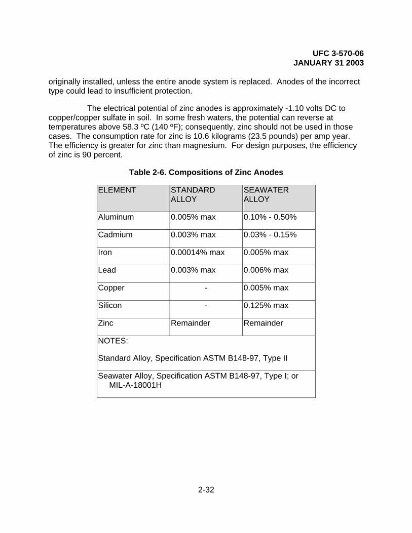
UFC 3-570-06 JANUARY 31 2003
2-32
originally installed, unless the entire anode system is replaced. Anodes of the incorrect type could lead to insufficient protection.
The electrical potential of zinc anodes is approximately -1.10 volts DC to copper/copper sulfate in soil. In some fresh waters, the potential can reverse at temperatures above 58.3 ºC (140 ºF); consequently, zinc should not be used in those cases. The consumption rate for zinc is 10.6 kilograms (23.5 pounds) per amp year. The efficiency is greater for zinc than magnesium. For design purposes, the efficiency of zinc is 90 percent.
Table 2-6. Compositions of Zinc Anodes
ELEMENT STANDARD ALLOY
SEAWATER ALLOY
Aluminum 0.005% max 0.10% - 0.50%
Cadmium 0.003% max 0.03% - 0.15%
Iron 0.00014% max 0.005% max
Lead 0.003% max 0.006% max
Copper - 0.005% max
Silicon - 0.125% max
Zinc Remainder Remainder
NOTES:
Standard Alloy, Specification ASTM B148-97, Type II
Seawater Alloy, Specification ASTM B148-97, Type I; or MIL-A-18001H
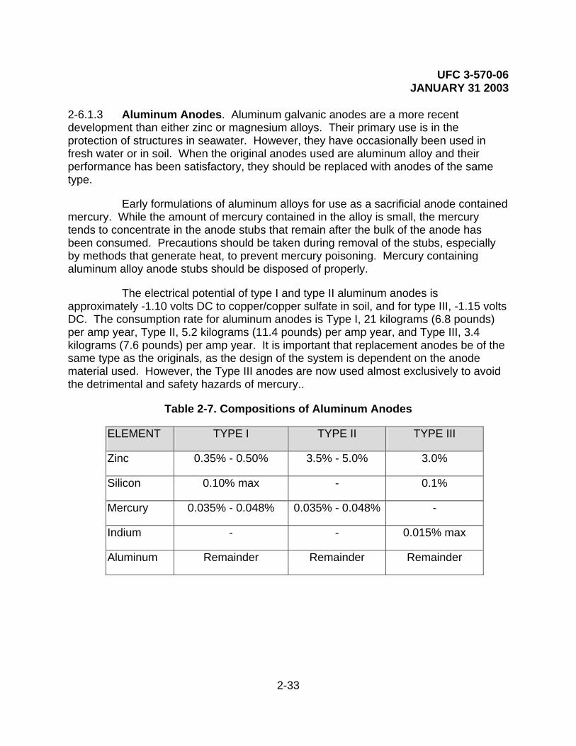
UFC 3-570-06 JANUARY 31 2003
2-33
2-6.1.3 Aluminum Anodes. Aluminum galvanic anodes are a more recent development than either zinc or magnesium alloys. Their primary use is in the protection of structures in seawater. However, they have occasionally been used in fresh water or in soil. When the original anodes used are aluminum alloy and their performance has been satisfactory, they should be replaced with anodes of the same type.
Early formulations of aluminum alloys for use as a sacrificial anode contained mercury. While the amount of mercury contained in the alloy is small, the mercury tends to concentrate in the anode stubs that remain after the bulk of the anode has been consumed. Precautions should be taken during removal of the stubs, especially by methods that generate heat, to prevent mercury poisoning. Mercury containing aluminum alloy anode stubs should be disposed of properly.
The electrical potential of type I and type II aluminum anodes is approximately -1.10 volts DC to copper/copper sulfate in soil, and for type III, -1.15 volts DC. The consumption rate for aluminum anodes is Type I, 21 kilograms (6.8 pounds) per amp year, Type II, 5.2 kilograms (11.4 pounds) per amp year, and Type III, 3.4 kilograms (7.6 pounds) per amp year. It is important that replacement anodes be of the same type as the originals, as the design of the system is dependent on the anode material used. However, the Type III anodes are now used almost exclusively to avoid the detrimental and safety hazards of mercury..
Table 2-7. Compositions of Aluminum Anodes
ELEMENT TYPE I TYPE II TYPE III
Zinc 0.35% - 0.50% 3.5% - 5.0% 3.0%
Silicon 0.10% max - 0.1%
Mercury 0.035% - 0.048% 0.035% - 0.048% -
Indium - - 0.015% max
Aluminum Remainder Remainder Remainder

UFC 3-570-06 JANUARY 31 2003
2-34
Table 2-8. Sacrificial Anodes Available Voltage for Cathodic Protection
POTENTIAL DIFFERENCE (DRIVING FORCE) FOR CATHODIC PROTECTION
MAGNESIUM ANODES
ZINC ANODES ALUMINUM ANODES
Protected Structure
Standard High Purity
Standard Seawater Type I Type Ii Type III
Steel 0.7 0.9 0.25 0.25 0.25 0.25 0.3
Aluminum 0.45 0.65 0 0 0 0 0.05
Stainless Steel
0.7 0.9 0.25 0.25 0.25 0.25 0.3
Copper 1.05 1.25 0.6 0.6 0.6 0.6 0.65

UFC 3-570-06 JANUARY 31 2003
2-35
Table 2-9. Estimated Output Current of Sacrificial Anodes
ESTIMATED ANODE CURRENT OUTPUT IN MILLIAMPERES (mA) (SEE NOTE)
ELECTROLYTE RESISTIVITY (OHM-CM)
ANODE MATERIAL
SIZE(INCHES) WEIGHT (POUNDS)
500 1000 2000 4000 8000 16000 32000 64000
High Purity Magnesium
3x3x5 3 127 64 32 16 8 4 2 1
High Purity Magnesium
2.75x2.75x26 9 242 121 61 30 15 8 4 2
High Purity Magnesium
3.75x3.75x60 40 413 206 103 52 26 13 6 3
High Purity Magnesium
3x3x78 42 456 228 114 57 29 14 7 4
Magnesium 3x3x5 3 102 51 25 13 6 3 2 1
Magnesium 2.75x2.75x26 9 194 97 48 24 12 6 3 2
Magnesium 3.75x3.75x60 40 330 165 83 41 21 10 5 3
Magnesium 3x3x78 42 365 182 91 46 23 11 6 3
Zinc 3x3x5 3 42 21 11 5 3 1 1 0
Zinc 2.75x2.75x26 9 81 40 20 10 5 3 1 1
Zinc 3.75x3.75x60 40 138 69 34 17 9 4 2 1
Zinc 3x3x78 42 152 76 38 19 10 5 2 1
Note: For protection of well-coated steel (single vertical anode, 3 meters (10 feet) from structure).

UFC 3-570-06 JANUARY 31 2003
2-36
Table 2-10. Applicable Tables In MIL-HDBK-1004/10
Table TITLE
12 Standard Alloy Magnesium Anodes, Standard Sizes for Use in Soil
13 Standard Alloy Magnesium Anodes, Standard Sizes for Use in Water
14 Standard Alloy Magnesium Anodes, Standard Sizes for Use in Condensers and Heat Exchangers
15 Standard Alloy Magnesium Anodes, Elongated for High Current Output
16 High Potential Alloy Magnesium Anodes, for Use in Soil or Water
17 Standard Alloy Magnesium Anodes, Extruded Rod for Use in Water Tanks and Heaters
18 Standard Sizes of Zinc Anodes, for Use in Soil or Fresh Water
19 Special Sizes of Zinc Anodes, for Use in Soil or Fresh Water
20 Standard Sizes of Zinc Anodes, for Use in Seawater
21 Special Sizes of Zinc Anodes, for Use in Seawater
22 Aluminum Pier and Piling Anodes, Standard Sizes
23 Type I Aluminum Alloy Anodes, Standard Sizes for Offshore Use
24 Type III Aluminum Alloy Anodes for Offshore Use
25 Aluminum Alloy Hull Anodes, Standard Sizes (Types I, II, and III)
26 Aluminum Alloy Bracelet Anodes, Standard Sizes

UFC 3-570-06 JANUARY 31 2003
2-37
2-6.2 Advantages and Disadvantages of Galvanic Anode Systems
2-6.2.1 Advantages
• Economically feasible when installed with the structure.
• Very little operation or maintenance requirements (very small chance of premature failure or breakdown).
• Extremely small possibility of overprotection (which may cause coating damage or hydrogen embrittlement).
• Small likelihood of stray current causing interference damage to other metallic (foreign) structures.
2-6.2.2 Disadvantages
• Small driving voltage available (limited potential difference).
• Extremely small current available in higher resistivity electrolytes.
• Not economically feasible to install or replace anodes on large or extensive existing structures.
2-6.3 Installation of Galvanic Anodes. Galvanic anodes used to protect buried structures are normally buried a short distance from the structure and connected to the structure using an insulated copper wire. Chemical backfill material is almost always used around sacrificial anodes in soil. The backfill may be installed dry, as a water slurry, or as part of a prepackaged unit. The special backfill is used to provide a uniform electrolyte, maintain moisture, and lower the resistance to earth to allow the anode to produce the required electrical current in an efficient and reliable manner. This backfill is normally 75 percent gypsum, 20 percent bentonite, and 5 percent sodium sulfate. Figure 2-20 shows the desired result of the installation of a sacrificial anode with backfill. It is not normally necessary to remove the consumed anodes.

UFC 3-570-06 JANUARY 31 2003
2-38
Figure 2-20. Galvanic Anode Installation
Special Backfill
Metallic connection
Anode
Pipeline(Cathode)
Test Lead
Below Bottom of Pipeline
Galvanic anodes used in immersion service are usually either directly attached to the surface being protected, or are suspended adjacent to it. When replacement of such anodes is necessary, they should be replaced using the same anodes as were originally used. All mounting hardware should be carefully inspected and repaired or replaced as necessary to insure that the anodes remain in place and that electrical contact is maintained.
2-6.4 Galvanic Anode Connection to Structure. Electrical contact between the galvanic anodes and the structure being protected is vital to the protection of the structure. In directly attached systems, this contact is achieved through the mounting system. The anodes are either directly welded or bolted to the structure. For anodes suspended in water, contact with the structure is achieved either through the mounting system or through insulated copper jumper wires that are welded to both the anode core and to the structure being protected. In systems where the anodes are not directly mounted on the structure being protected, connection is normally achieved using an insulated copper wire. The wire is either cast into the anode during manufacture or welded to the anode core. Connection to the structure usually is achieved by welding the wire to the structure. When additional wire is required for the connection, wire of the proper size using type TW insulation is usually used.
Thermite welding is widely used in installation, maintenance, and repair of cathodic protection systems. The process can be used to connect wires to the structure or anode cores or to connect two or more wires together. All connections and splices should be insulated when exposed to soil or water to prevent loss of good electrical contact.

UFC 3-570-06 JANUARY 31 2003
2-39
Clamps are also used for connection of anode wires to the structure; or, more commonly, for splicing. To insure good electrical connection, the clamps and wires must be clean and the clamps must be properly tightened. Clamped connections should be insulated when exposed to soil or water in order to prevent loss of good electrical contact.
2-6.5 Galvanic Test Stations. Test stations are included in galvanic anode cathodic protection systems on buried structures to facilitate inspection of the system. The test stations may be located above the surface in connection boxes or in subsurface test stations mounted flush on grade. Typical test stations are shown in Figures 21 and 22.
Figure 2-21. Above Grade Test Station
Conduit
Anode Lead
Pipeline
Structure Leads
Test Station
Metallic Connection
Pole, Post or Wall (for Physical Protection)

UFC 3-570-06 JANUARY 31 2003
2-40
Figure 2-22. Subsurface Test Station
Anode Lead
Pipeline
Structure Leads
Test Station
Metallic Connection
Test stations are used to conduct many different tests in cathodic protection systems. For galvanic anode systems, the most common test station measures the potential of the structure nearest the anode, the potential of the structure farthest from the anode, the potential of the anode, and the amount of current being supplied by an anode or group of anodes. The connections in this type of test station are shown in Figure 2-23.
Figure 2-23. Potential - Current Test Station Connections
Measure Structure Potential Here
Anode LeadStructure Leads
Test Station
Current Shunt
Measure Anode Current Here(by mV potential drop)

UFC 3-570-06 JANUARY 31 2003
2-41
Normally, a test station has three wires as shown in Figure 2-23. Some test stations may not have current shunts, may not have a separate structure potential measurement lead, may have multiple anode leads, may just have one structure lead (anodes connected directly to structure), or there may be multiple anodes with a single lead.
Other types of test stations are described in the sections that describe the various tests performed using the test stations. It is important that the connections in the test stations be maintained in their original condition after use or when damaged. If the identities of the test station leads are unknown, the leads can be disconnected and the potential of each lead to a copper/copper sulfate reference electrode taken. Using the galvanic series (Table 2-2), the leads may be easily identified:
• High purity magnesium -1.75
• Standard magnesium -1.55
• Zinc -1.2, aluminum -1.1
• Structure leads -0.2 to -0.8 or slightly higher if with other anodes are still attached
2-7 IMPRESSED CURRENT CATHODIC PROTECTION. As in galvanic anode systems, impressed current systems supply current for cathodic protection of a metal surface. However, in the case of an impressed current system, the protective current is supplied by a rectifier (or other DC power source) instead of by the natural potential difference of the anode to the structure. As shown in Figure 2-19, the potential difference between the anode and cathode is forced from a non-reactive anode bed by the action of additional energy from a rectifier to force the electron flow that would be normally produced in the corrosion reaction. The energy for the “electron energy pump” action of the rectifier is provided by ordinary alternating current. The effect of these electrons at the structure being protected is the same as that derived from the sacrificial anode type of cathodic protection system. However, the anode material serves only as a source of electrons and anodic (oxidation) electrochemical reactions.
In practice, materials such as graphite, high silicon cast iron (HSCI), platinum or mixed metal oxide, are used for impressed current cathodic protection system anodes because they are slowly consumed (they have a very low kilogram (pound) per amp year weight loss). To provide a uniform electrolyte, a lower resistance to earth, and venting of gases and acids, a special backfill is used. This earth contact backfill is normally coke breeze or calcined fluid petroleum coke. Anodes in impressed current systems must be periodically inspected and replaced if consumed or otherwise damaged. As is the case for any electrical equipment, rectifiers used for impressed current cathodic protection systems require preventive maintenance and recurring

UFC 3-570-06 JANUARY 31 2003
2-42
operational checkouts to ensure proper operation. Impressed current system anode leads must have a special insulation to preclude the copper lead wire from becoming part of the anode system. Since the power source is forcing everything connected to the positive terminal to act as an anode (and corrode) any defect or nick in the insulation of the anode lead wire would result in copper metal loss ending in failure of the anode system.
Figure 2-24. Impressed Current Cathodic Protection System
Current Flow in the Earth
Rectifier
AnodeTANK
Current Flow in the Earth
Anode(Cathode)
Test Lead
Metallic Anode Selected for low weight loss (Usually Graphite or HSCI)
(+)(−)(or other DC Power Source)
Impressed current systems are fundamentally the same as galvanic anode systems in their operation, except that in impressed current systems a rectifier or other direct current power source is used to increase the potential of the electrons from the anodes to provide the desired protective current. Thus, as shown in Figure 2-24, in addition to an anode and a connection to the structure being protected, an impressed current cathodic protection system uses a rectifier or other power source. A battery, solar cell, direct current generator, or thermoelectric generator may be used as a power source. However, nearly all impressed current cathodic protection systems use alternating current or solar powered rectifiers as a power source.
2-7.1 Impressed Current Rectifiers. Rectifiers used for cathodic protection commonly use an adjustable step down transformer, rectifier stacks, a shunt to measure output current, meters to indicate output current and voltage, circuit breakers, lightning arresters, and transformer tap connections, all in one case. The function of the rectifier is to convert alternating current into controlled (pulsating) direct current. A typical pole mounted rectifier for cathodic protection service is shown in Figure 2-25.
2-7.1.1 Rectifier Stacks are of two general types: selenium plates or silicon diodes.

UFC 3-570-06 JANUARY 31 2003
2-43
In high voltage or high current units, silicon diodes should be used. Selenium units have a higher voltage drop (less efficient) and are less affected by voltage surges, and they “age” over time and must be eventually replaced. Silicon diode units are susceptible to damage by voltage or current spikes and must be protected from these surges by metal oxide varistors (surge protectors) as well as the normal lightning protection provided all units.
2-7.1.2 Rectifiers are either automatically controlled or manually controlled. On manually controlled units, the transformer tap connections normally encircle the “center tap” connections. The center tap connections are the input to the stacks, and the negative and positive lugs are the output from the stacks.
Automatic rectifiers are sometimes used when the structure size (elevated water tanks which vary in water levels) is constantly changing, or when the cathodic protection circuit resistance (anode-to-earth resistance due to extreme dry-to-wet conditions) changes significantly at a given location. These units can be potential-controlled, current-controlled, or voltage-controlled. Potential-controlled units are normally used in elevated water tanks to maintain a set potential on a permanent reference cell located inside the tank. Since in this condition the amount of structure to be protected is constantly changing as the water level changes, the amount of current required is constantly changing, so a current-controlled or voltage-controlled unit must not be used. When the cathodic protection circuit resistance changes significantly at a given location due to the anode-to-earth resistance being affected by extreme dry-to-wet conditions, current-controlled units are used to maintain the correct current applied to the structure being protected. Voltage-controlled units must not be used in this case, but potential-controlled units could be used, with an added permanent reference cell (which adds another component which could possibly be damaged or fail).
2-7.1.3 There are normally meters and/or a shunt inline between the stacks and the output lug, lightning protection on the AC input and the DC output, output filters and/or capacitors to increase efficiency, and circuit breakers to turn the unit on and off.
2-7.1.4 Quick disconnects, usually near the rectifier, are normally fused and serve to turn power off to the rectifier. Details of the construction, operation, maintenance and repair of cathodic protection rectifiers are given in portions of Chapters 4, 5 and 7 of this handbook.

UFC 3-570-06 JANUARY 31 2003
2-44
Figure 2-25. Impressed Current Cathodic Protection System Rectifier
+-
1
2
0
34 5
6
7
8
AMMETER
2
4
0
68
10
12
14
16
VOLTMETER
2-7.2 Impressed Current Anode Materials. The anodes of an impressed current system provide the means for the protective current to enter the electrolyte. Since the anodes form the corroding part of the system, the best material is one that has a low rate of weight loss per ampere-year (Table 2-11). The most commonly used materials for impressed current anodes are graphite and high-silicon cast iron. Aluminum is sometimes used in water storage tanks. In areas where heavy icing is not a problem, high silicon cast iron anodes are used instead of aluminum for lower long-term cost. Platinum coated titanium or niobium anodes and mixed metal oxide anodes are becoming more prevalent as impressed current anode material.
Before the 1970s, there were only three types of anodes primarily used for impressed current groundbeds—high silicon cast iron, graphite, and scrap steel. As technology progressed, so did the types of materials that are commonly used by corrosion personnel. The materials have specialized applications and, when installation and operating costs are assessed, very few anodes can be used universally for any type of application and still achieve a desirable design life. In most soils, anodes evolve oxygen and the anode oxidizes as the current is discharged. In chloride containing soils or water, anodes evolve chlorine gas that forms hydrochloric acid, and the anodes break down chemically. The whole purpose of this explanation is to point out that some anodes perform well in the presence of oxygen and others in the presence of acids.

UFC 3-570-06 JANUARY 31 2003
2-45
Table 2-11. Electrochemical Equivalents Of Common Structural Metals
WEIGHT LOSS
METAL KILOGRAMS (POUNDS) PER AMPERE YEAR
Carbon (Graphite) 1 (2.2)
Iron 9.1 (20.1)
Aluminum 2.9 (6.5)
Lead 33.9 (74.5)
Copper 10.3 (22.8)
Zinc 10.7 (23.6)
Magnesium 4 (8.8)
Nickel 9.6 (21.1)
Silver 35.2 (77.6)
Tin 19 (42)
2-7.2.1 High Silicon Cast Iron. Cast iron anodes are produced in two alloy types with the principal addition of chromium, developed in 1959, to improve the life in chloride soils and water. Table 2-12 shows the metallurgical composition of the two alloys. The principal reason for superior cast iron performance is the formation of a silicon oxide (Si02) film that forms on the anode surface, reducing the rate of oxidation, and retarding the consumption rate. They have good electrical properties, and the resistance of the alloy is 72 micro-ohms per cubic centimeter at 20 ºC. To be successful in soils, the anodes are backfilled with metallurgical or petroleum coke breeze to reduce the anode resistance and increase the effective anode surface area. Even when the anodes are pre-packaged in coke breeze filled canisters, filling the annular space between the canister and the soil with additional coke breeze is a recommended practice. In seawater, the anode will discharge current at very low voltages and, therefore, does not require backfill. Manufacturers of cast iron anodes developed cable-to-anode connection procedures which distributors are required to follow. Therefore, there has been a lower incidence of connection failures, compared to

UFC 3-570-06 JANUARY 31 2003
2-46
graphite anodes. The anodes exhibit superior conductivity and experience very little change in resistance with time, unless the anode is damaged. The high tensile strength of the metal is an asset in some circumstances, except that their very low elongation makes them brittle and subject to fracture from severe mechanical and thermal shock.
Cast iron anodes are manufactured in a wide variety of dimensions, shapes, and weights. Refer to Table 2-13 for a description of the various sizes. A proprietary type of cast iron anode, originally manufactured from “off-specification” corrosion resistance piping, is called a tubular anode. This uses the ASTM 518 Grade 2 chromium alloy and has demonstrated since 1971 to have superior resistance to “end effect,” common to anodes with poor connection resistance values.
Table 2-12. Cast Iron Composition
ASTM 518
Element Grade 1 Grade 2
Silicon 14.2 - 14.75% 14.2 - 14.75%
Manganese 1.5% max. 1.5% max.
Chromium - 3.25 - 5.0%
Carbon 0.75 - 1.15% 0.75 – 1.15%
Copper 0.50% max. 0.50% max.
Iron Balance Balance
Soil 0.45 kg (1 lb)/amp-year 0.34 kg (0.75 lb)/amp-year Consumption Rate
Seawater 8.4 kg (18.5 lb)/amp-year 0.11 kg (0.25 lb)/amp-year

UFC 3-570-06 JANUARY 31 2003
2-47
Table 2-13. Cast Iron Anodes
Size (inches)
Nominal Weight (kg[lb])
Area (m2[ft2]) Cable Size (maximum)
1.1 x 9 0.45(1) 0.018(0.2) #8
1.5 x 9 1.8(4) 0.029(0.3) #6
2 x 9 2.26(5) 0.037(0.4) #4
3 x 3 2.72(6) 0.023(0.25) N/A
1 x 30 3.18(7) 0.065(0.7) #6
1 x 60 5.44(12) 0.13(1.4) #6
1.5 x 60 5.44(12) 0.093(1.0) #6
1.5 x 30 5.9(13) 0.093(1.0) #6
6 x 2.5 7.26(16) 0.046(0.5) N/A
1.5 x 60 11.34(25) 0.18(2.0) #6
1.5 x 60 11.8(26) 0.18(2.0) #6
1.5 x 60 11.8(26) 0.18(2.0) #6
2 x 30 13.61(30) 0.12(1.3) #1/0
2 x 60 19.96(44) 0.24(2.6) #6
12 x 3.5 24(53) 0.093(1.0) N/A
2 x 60 27.2(60) 0.26(2.8) #1/0
3 x 36 36.29(80) 0.23(2.5) #1/0
3 x 60 49.9(110) 0.37(4.0) #1/0
4.5 x 60 99.8(220) 0.54(5.8) #1/0

UFC 3-570-06 JANUARY 31 2003
2-48
2-7.2.2 Graphite Anodes. Graphite rods have been used as an impressed current material for many years. The basic configurations consist of round or square rods, manufactured from a slurry of powdered petroleum coke and coal tar resin. The coal tar is used as a bonding agent to hold the graphite particles together and then baked for a month at high temperatures to fuse the mixture. This process increases the resistance to oxidation and subsequent breakdown. There are many types of graphite compositions and the type used for cathodic protection groundbeds is one of the most porous. The porosity allows moisture penetration to eventually migrate to the connection, causing failure at the cable connection. A denser anode is expensive; therefore, the porosity is reduced by impregnating the rods with an inexpensive filler of linseed oil, microcrystalline wax, or a phenolic-based resin. There is controversy concerning the best type of filler and even whether filler really reduces moisture penetration over long periods of time. Some fillers have caused deep well anode ground beds to become fouled and develop a high circuit resistance when the anodes have been driven at high current density levels.
It is very important to have a proper anode-to-cable connection with any anode material. For years, the manufacturers of graphite anodes had no specification for a proper anode lead wire connection. This led to varying procedures and numerous failures attributable to poor material, poor workmanship, and no quality control parameters prior to shipment. Many users have developed their own assembly standards that make graphite anodes a customized and consequently, more expensive product than it could be if an industry standard existed. Additional specification details should include:
• Type of container - lead, brass, molten, compression.
• Connection depth/diameter – 76 mm (3 in), 102 mm (4 in), 127 mm (5 in), centered.
• Connection sealant - thermoplastic, thermosetting (epoxy).
• Cable sealant - TFE tubing, shrink cap, encapsulation.
• Impregnation - wax, linseed oil, resin.
• Sizes - 3”x30”, 3”x60”, 4”x40”, 4”x80”.
Graphite should not be operated at current densities exceeding 10.76 amperes per square meter (1 ampere per square foot) in soil or 2.70 amperes per square meter (0.25 amperes per square foot) in water. Unfortunately, graphite is brittle and may be easily damaged during transportation, either bare or packaged. Special handling and padding is necessary to prevent cracking and breaking.
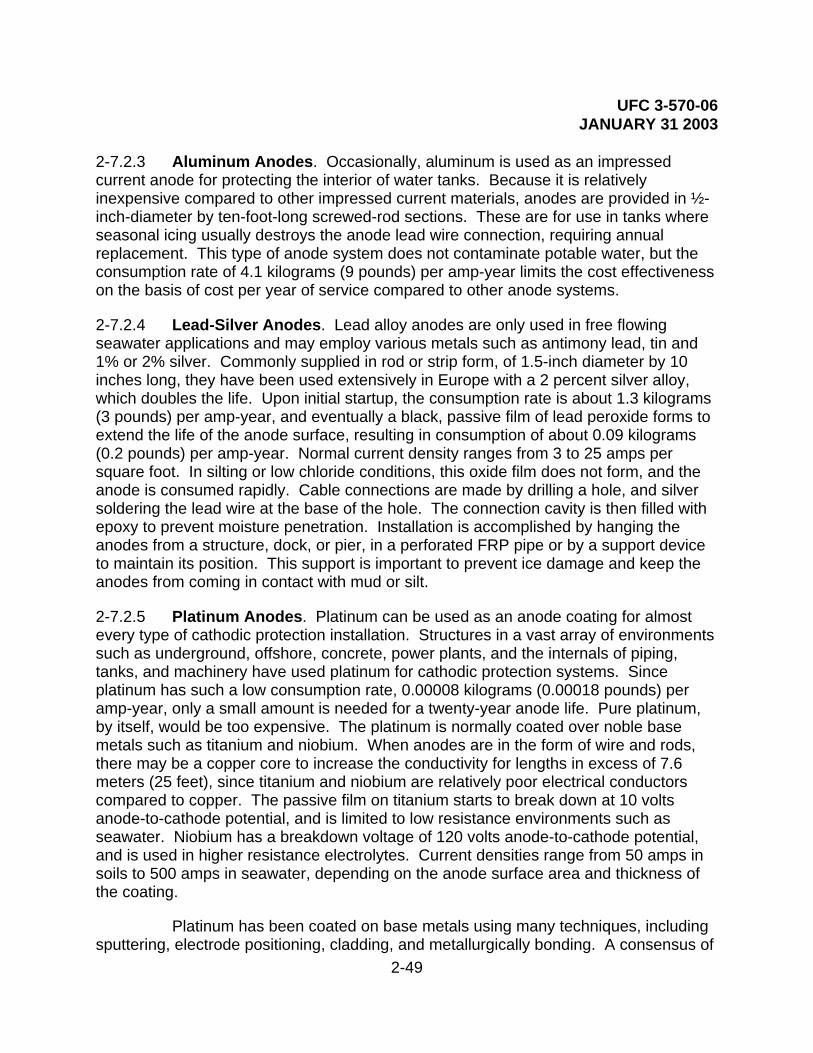
UFC 3-570-06 JANUARY 31 2003
2-49
2-7.2.3 Aluminum Anodes. Occasionally, aluminum is used as an impressed current anode for protecting the interior of water tanks. Because it is relatively inexpensive compared to other impressed current materials, anodes are provided in ½-inch-diameter by ten-foot-long screwed-rod sections. These are for use in tanks where seasonal icing usually destroys the anode lead wire connection, requiring annual replacement. This type of anode system does not contaminate potable water, but the consumption rate of 4.1 kilograms (9 pounds) per amp-year limits the cost effectiveness on the basis of cost per year of service compared to other anode systems.
2-7.2.4 Lead-Silver Anodes. Lead alloy anodes are only used in free flowing seawater applications and may employ various metals such as antimony lead, tin and 1% or 2% silver. Commonly supplied in rod or strip form, of 1.5-inch diameter by 10 inches long, they have been used extensively in Europe with a 2 percent silver alloy, which doubles the life. Upon initial startup, the consumption rate is about 1.3 kilograms (3 pounds) per amp-year, and eventually a black, passive film of lead peroxide forms to extend the life of the anode surface, resulting in consumption of about 0.09 kilograms (0.2 pounds) per amp-year. Normal current density ranges from 3 to 25 amps per square foot. In silting or low chloride conditions, this oxide film does not form, and the anode is consumed rapidly. Cable connections are made by drilling a hole, and silver soldering the lead wire at the base of the hole. The connection cavity is then filled with epoxy to prevent moisture penetration. Installation is accomplished by hanging the anodes from a structure, dock, or pier, in a perforated FRP pipe or by a support device to maintain its position. This support is important to prevent ice damage and keep the anodes from coming in contact with mud or silt.
2-7.2.5 Platinum Anodes. Platinum can be used as an anode coating for almost every type of cathodic protection installation. Structures in a vast array of environments such as underground, offshore, concrete, power plants, and the internals of piping, tanks, and machinery have used platinum for cathodic protection systems. Since platinum has such a low consumption rate, 0.00008 kilograms (0.00018 pounds) per amp-year, only a small amount is needed for a twenty-year anode life. Pure platinum, by itself, would be too expensive. The platinum is normally coated over noble base metals such as titanium and niobium. When anodes are in the form of wire and rods, there may be a copper core to increase the conductivity for lengths in excess of 7.6 meters (25 feet), since titanium and niobium are relatively poor electrical conductors compared to copper. The passive film on titanium starts to break down at 10 volts anode-to-cathode potential, and is limited to low resistance environments such as seawater. Niobium has a breakdown voltage of 120 volts anode-to-cathode potential, and is used in higher resistance electrolytes. Current densities range from 50 amps in soils to 500 amps in seawater, depending on the anode surface area and thickness of the coating.
Platinum has been coated on base metals using many techniques, including sputtering, electrode positioning, cladding, and metallurgically bonding. A consensus of

UFC 3-570-06 JANUARY 31 2003
2-50
knowledgeable engineers finds that metallurgically bonded anodes seem to experience fewer failures because the metals are compressed together in an oxygen-free vacuum. This provides an oxide-free, low resistance, and complete bond between the metals, thereby maximizing design life. Cladding involves wrapping a thin sheet of platinum around a rod and spot-welding the platinum to the base metal at the overlap area. The limited weld area allows the underlying base metal to oxidize, thus increasing resistance and achieving minimal design life. The smooth surface has little bearing on the life, because the surface becomes irregular once current is discharged. Electro-deposition techniques plate a film of platinum on the base metal, but the process results in a porous surface that is less likely to achieve full life due to high resistance oxide film formation. Thermal decomposition and welded techniques exhibit the same problems as cladding and, as of the late 1980s, are rarely used.
The anode-to-cable connection is critical, and improper connections can result in premature failure. Users should assure that the anodes are manufactured in compliance with their specifications by skilled personnel under the guidance of established quality control methods. The major disadvantage of platinum is its poor resistance to anode acid evolution in static electrolytes, rippled direct current, and half wave rectifiers. Use of a three-phase transformer rectifier in seawater systems has been known to double the life of platinum anodes by reducing the ripple on the DC output.
2-7.2.6 Ceramic and Mixed-Metal Oxide Anodes. Mixed-metal oxide anodes were developed in Europe during the early 1960s for use in the industrial production of chlorine and caustic soda. The first known use of the technology for cathodic protection occurred in Italy to protect a seawater jetty in 1971. These anodes exhibit favorable design life characteristics while providing current at very high-density levels. The oxide film is not susceptible to rapid deterioration due to anode acid generation, rippled direct current, or half wave rectification, as is common with other precious metal anodes. The composition of the anode consists of a titanium rod, wire, tube or expanded mesh with the oxide film baked on the base metal. Sometimes they may be referred to as dimensionally stable, ceramic, or linear distributed anodes. In oxygen evolution environments such as soils, the oxide consists of ruthenium crystals and titanium halide salts in an aqueous solution that is applied like paint, on the base metal, and baked at 400 ºC to 800 ºC, forming a rutile oxide. In chlorine evolving environments such as seawater, the oxide consists of an aqueous solution of iridium and platinum powder that is also baked at high temperatures to achieve a desirable film. After baking, the rutile oxide develops a matte black appearance and is highly resistant to abrasion. Some manufacturers produce variations of the oxide films specifically for chloride or non-chloride electrolytes and they are not interchangeable. Normally, titanium will experience physical breakdown around 10 volts, but the oxide film is so highly conductive (0.00001 ohm-cm resistivity), that the current, which takes the path of least resistance, is discharged from the oxide rather than the base metal even with a rectifier voltage of 90 volts in soils. This is in contrast to the insulating titanium dioxide film that

UFC 3-570-06 JANUARY 31 2003
2-51
naturally forms on the surface of bare titanium. When the mixed metal oxide film has been consumed, the insulating titanium dioxide film will cover the anode and not allow current to discharge unless the applied voltage is greater than 10 volts in seawater, or 50 to 70 volts in fresh water.
The U.S. Army Construction Engineering Research Laboratory (USACERL) has developed a ceramic anode as a Facility Engineering Application Program (FEAP). Good performance of the ceramic anode has been demonstrated in a wide variety of applications. Procurement, material specifications, performance parameters, and application designs are detailed in Engineering Technical Letter (ETC) 1110-9-10 (ER). The following data details the maximum recommended current densities for various electrolytes:
• Soil, mud, fresh water: 100 amps per square meter (9.3 amps per square foot (20 years).
• Seawater: 600 amps per square meter (55.7 amps per square foot (15 years).
Anodes in soil or mud must be backfilled with fine, low resistance, calcined petroleum coke breeze for maximum life and performance. Even when the anode is pre-packaged with petroleum coke, conservative engineering judgment would dictate that the anode package be surrounded with metallurgical coke, prior to finishing the backfilling with native soil. Consumption rates at these densities range from 0.5 milligrams per amp-year in seawater to 5 milligrams per amp-year in coke breeze, fresh water, and sea mud. As with any anode, the connection must be constructed so as to be moisture proof, water tight and have no more than 0.001 ohms of resistance. Advantages of mixed metal oxide anodes:
• Lightweight and unbreakable
• Negligible consumption rate
• Inert to acid generation
• Dimensionally stable
• High current density output
• Cost-effective
2-7.2.7 Polymer Conductive Anodes. In 1982, a new anode material was test-marketed. The material provides a small amount of current in restricted spaces, such as internal pipe surfaces, heat exchangers, utility ducts, and areas shielded from

UFC 3-570-06 JANUARY 31 2003
2-52
conventional groundbed current. The material resembles electrical cable but actually consists of a stranded copper conductor with an extruded, conductive polyethylene jacket. This concept is used in underground concentric power cables as a conductive shield around the ground wires. The polymer contains carbon granules that discharge the current, leaving behind a polymer matrix. The anode should be backfilled in carbonaceous coke breeze for maximum life. Some manufacturers offer an optional plastic mesh, to separate the anode from the cathode in restricted spaces, preventing electrical shorting between the anode and cathode. Currently, the material is available in four different diameters and the current output ranges from 9.8 to 29.5 milliamperes per linear meter (3 to 9 milliamperes per linear foot).
Table 2-14. Applicable Tables In MIL-HDBK-1004/10
Table TITLE
1 Current Requirements for Cathodic Protection of Bare Steel
2 Current Requirements for Cathodic Protection of Coated Steel
5 Adjusting Factor for Multiple Anodes (F)
6 Correction Factor - Short Line Coating Conductance
7 Results of Structure-to-Electrolyte Potential Measurements
8 Standard HSCBCI Anodes
9 Special HSCBCI Anodes
10 Standard Wire Characteristics
11 M Factors for Determining Economic Wire Size (Cost of Losses in 100 Feet of Copper Cable at 1 Cent per kWh)
2-7.3 Types of Impressed Current Anode Beds. The types of impressed current anode beds are dependent on the placement, orientation, and depth of the anodes. Impressed current anode beds are normally placed in remote earth, and distribute current over long distances of the protected structure (pipelines, tank farms, distribution systems etc.). Distributed impressed current groundbeds are sometimes used for small

UFC 3-570-06 JANUARY 31 2003
2-53
structures (valves, tanks), and the anodes are evenly distributed along the structure to be protected, each anode protecting a small portion of the whole structure. Distributed impressed current systems are commonly used to protect the interiors of water storage tanks, both ground level and elevated structures. The remote type of groundbed can be installed near the surface, either horizontally or vertically, or they can be installed deep. Distributed systems are installed like the previously discussed sacrificial anodes, with the addition of a continuous header cable which connects the anodes to the rectifier (or other power source) and a structure lead from the power source to the protected structure.
2-7.3.1 Vertical Remote Impressed Current CP Systems. These systems are commonly used for pipelines in remote areas. This is usually the most economical choice when there are not other utilities in the area and there is sufficient room to locate the anodes remote from the structure. Vertical placement of the anodes in the earth tends to lower the total resistance to earth of the system (versus horizontal). The distance to remote earth varies according to the resistivity of the earth, usually 91 to 213 meters (300 to 700 feet).
Soil resistivity testing should be done in the area of a proposed anode bed to locate an area of low resistance to place the anodes. Care must be taken to ensure that that low resistance area is not continuous to the protected structure. Poor current distribution may occur if this condition occurs. In some cases, the best location for an anode bed may be in higher resistivity earth. The resistance of the anode bed can be lowered by adding additional anodes, using longer anodes, or by increasing the spacing of the anodes.
Figure 2-26. Vertical Remote Impressed Current Cathodic Protection System
Special Backfill Vertical orHorizontal
Anodes
PIPELINE (CATHODE)
AnodeLeadStructure
LeadTypically Over 400 Feet
2-7.3.2 Horizontal Remote Impressed Current CP Systems. These systems are commonly used for pipelines in remote areas where a rock stratum is located near the surface or where other soil conditions would require horizontal installation to ensure the

UFC 3-570-06 JANUARY 31 2003
2-54
anode is in a uniform environment. This is usually the most economical choice when there are not other utilities in the area, there is sufficient room to locate the anodes remote from the structure, and there is a rock strata near the surface. Horizontal placement of the anodes in the earth tends to raise the total resistance to earth of the system (versus vertical). The distance to remote earth varies according to the resistivity of the earth, usually 91 to 213 meters (300 to 700 feet).
Soil resistivity testing can be done in the area of a proposed anode bed to locate an area of low resistance to place the anodes. Care must be taken to ensure that the low resistance area is not continuous to the protected structure. Poor current distribution may occur if this condition occurs. In some cases, the best location for an anode bed may be in higher resistivity earth. The resistance of the anode bed can be lowered by adding additional anodes, using longer anodes, or by increasing the spacing of the anodes. The anodes may have individual leads connected to a header cable or they may be installed on a continuous cable.
Figure 2-27. Horizontal Remote Impressed Current Cathodic Protection System
2-7.3.3 Distributed Impressed Current CP Systems. These systems are commonly used to protect small structures. This is usually the most economical choice when the structure is small or the anodes cannot be placed in remote earth. This type of anode bed is used to protect water tank interiors, ground level tank bottoms, underground storage tanks, or a short pipeline. Anodes are distributed along the pipeline, or around the surface of the tank (interior for water tanks, exterior for underground tanks). The distance from the structure is normally 1.5 to 3 meters (5 to 10 feet), and the distance between anodes is normally double that distance (3 to 6 meters [10 to 20 feet]). In some cases, the anode is continuous, and is placed in a grid pattern on tanks, or along the side of a pipeline.
Special Backfill HorizontalAnodes
PIPELINE (CATHODE)
AnodeLeadStructure
LeadTypically Over 400 Feet

UFC 3-570-06 JANUARY 31 2003
2-55
Figure 2-28. Distributed Impressed Current Cathodic Protection System
2-7.3.4 Deep Remote Impressed Current CP Systems. These systems are commonly used to protect large structures in built up areas. This is usually the most economical choice when the structure is large, in an area with many other utilities, or the anodes cannot be placed near the surface. This type of anode bed is used to protect pipeline distribution systems, aboveground tank farms, and pipelines in built-up areas. The anodes are placed in remote earth by drilling deep below the surface. The typical deep anode bed is 30.5 meters (100 feet) to the top anode, and from 61 to 183 meters (200 to 600 feet) to the bottom anode. The anodes can be on individual leads, spaced on a continuous cable, or be a continuous anode wire. This type of anode bed can have a much higher current capacity than typical surface anode systems. This type of system minimizes interference to other metallic structures. This system requires special consideration for backfill, cable insulation, and venting.
Figure 2-29. Deep Remote Impressed Current Cathodic Protection System
RectifierRectifier
AnodesAnodesBackfillBackfill
100 Ft
100-500 Ft
Pipeline(Cathode)
Pea GravelPea GravelEnvironmentalEnvironmental
SealSeal
Well CapWell Cap
CasingCasing
-- ++
AnodesAnodes
AnodesAnodes
PermanentPermanentReferenceReferenceElectrodesElectrodes
ThermitThermit Weld Weld
Two StageTwo StageAuto RectifierAuto Rectifier

UFC 3-570-06 JANUARY 31 2003
2-56
2-7.4 Advantages and Disadvantages of Impressed Current Anode Systems
2-7.4.1 Advantages:
• Economically feasible when installed on existing structures.
• Large voltage available (potential difference limited only by the size of power supply).
• Large current available, even in very high resistivity electrolytes.
• Can provide sufficient current to protect very large, poorly coated, or uncoated structures.
• Economically feasible to replace anode system when required.
2-7.4.2 Disadvantages:
• Significant operation and maintenance requirements.
• Relatively large chance of premature failure or breakdown.
• Possibility of stray current causing interference damage to other metallic (foreign) structures.
2-7.5 Impressed Current Test Stations. Test Stations for structures with impressed current cathodic protection systems normally are merely contact points for the positive connection of a voltmeter to allow for potential testing. Normally, there are two wires to the test station to permit test lead verification and redundancy. Also, impressed current systems require the same test stations as galvanically protected structures for casings, isolations, and bonding, with a higher likelihood for interference bonds. Any location where the structure is assessable could be considered a test station. These locations could be where a pipeline goes through a valve pit, low level drain pit, high level drain pit, exposed crossing a ditch, goes aboveground for a valve or meter, or enters a building or any other location where it is exposed.
Test stations should be installed wherever the structure is inaccessible to allow the ability to test the cathodic protection system(s). Examples of such areas include paved areas and structures under concrete slabs. In these cases, the test stations provide a contact point for the reference electrode as well as test leads to the structure.

UFC 3-570-06 JANUARY 31 2003
2-57
Figure 2-30. Flush Test Station
Pipeline
Structure Leads
Test Station

UFC 3-570-06 JANUARY 31 2003
2-58
Figure 2-31. Abovegrade Test Station
Pole, Post or Wall (for Physical Protection)
Line Marker Type (Screw off cover)Type LB,
with Externalconnection
points
Test Stationwithremovablecover

UFC 3-570-06 JANUARY 31 2003
3-1
CHAPTER 3
REQUIREMENTS
3-1 APPLICABLE STANDARDS. Installed CP systems must provide protective potential satisfying Chapter 6 of this handbook and appropriate NACE Standards.
• RP0169, Corrosion Control of External Corrosion on Underground or Submerged Metallic Piping Systems.
• RP0285, Corrosion Control of Underground Storage Tanks By Cathodic Protection.
• RP0388, Impressed Current Cathodic Protection of Internal Submerged Surfaces of Steel Water Storage Tanks.
• RP0193, External Cathodic Protection of On-Grade Metallic Storage Tank Bottoms.
• RP0196, Galvanic Anode Cathodic Protection of Internal Submerged Surfaces of Steel Water Storage Tanks.
All structure-to-earth potentials must be potential drop (IR) free in accordance with RP0169 or other appropriate NACE standard.
3-2 DESIGN AND CONSTRUCTION CONSIDERATIONS. The design and construction considerations that follow are based on experience and sound engineering practices. Corrosion control and cathodic protection personnel should ensure they are incorporated in projects and work orders where appropriate.
3-2.1 Ductile Iron Pipe. Ductile iron pipe requires CP, bonding of joints, and protective coatings in soil resistivities below 10,000 ohm-centimeters at installation depth at any point along the pipeline.
3-2.2 Soil Resistivities. When soil resistivities are above 10,000 ohm-centimeters at installation depth along the entire pipeline, ductile or cast iron pipe will require bonded joints only.
3-2.3 Joint Bonds. Joint bonds must use No. 4 AWG insulated wire.
3-2.4 Thermite Welds and Exposed Copper Wire. Thermite welds and exposed copper wire must be coated.
3-2.5 Copper. Copper water service lines and brass valves must be dielectrically

UFC 3-570-06 JANUARY 31 2003
3-2
isolated from ferrous pipe, or covered with a protective coating.
3-2.6 Metallic Ferrous Pipe. A metallic ferrous pipe passing through concrete must not be in contact with the concrete. Provide a sleeve with waterproof dielectric insulation between the pipe and the sleeve. Ferrous metal piping passing through a concrete thrust block must be insulated from the concrete or cathodically protected.
3-2.7 Lightning and Fault Current. The need for lightning and fault current protection at isolating devices (dielectrically insulated flanges) should be considered. Where a combustible atmosphere may be encountered, a sealed, weatherproof lightning arrester must be installed across each isolating device. The arrester should be the gapless, self-healing, solid-state type (metal oxide varistor). Cable connections from arresters to isolating devices should be short, direct, and of a size suitable for short-term, high-current loading.
3-3 SYSTEMS REQUIRING CATHODIC PROTECTION. Ensure both CP and protective coatings are provided for the following buried/submerged metallic structures, regardless of soil or water corrosivity:
• Natural gas piping.
• Liquid fuel piping.
• Oxygen piping.
• Underground storage tank (UST) systems.
• Fire protection piping.
• Ductile iron pressurized piping under floor (slab on grade).
• Underground heat distribution and chill water piping in metallic conduit.
• Facilities with hazardous products as identified by the major commands, major claimants, or other competent authorities.
Results of an economic analysis and recommendations by a qualified corrosion engineer must govern the application of CP and protective coatings on gravity sewer lines, regardless of soil resistivity, and the following facilities in soil resistivities above 10,000 ohm-centimeters:
• Potable water lines.
• Other buried/submerged metallic facilities not covered above.
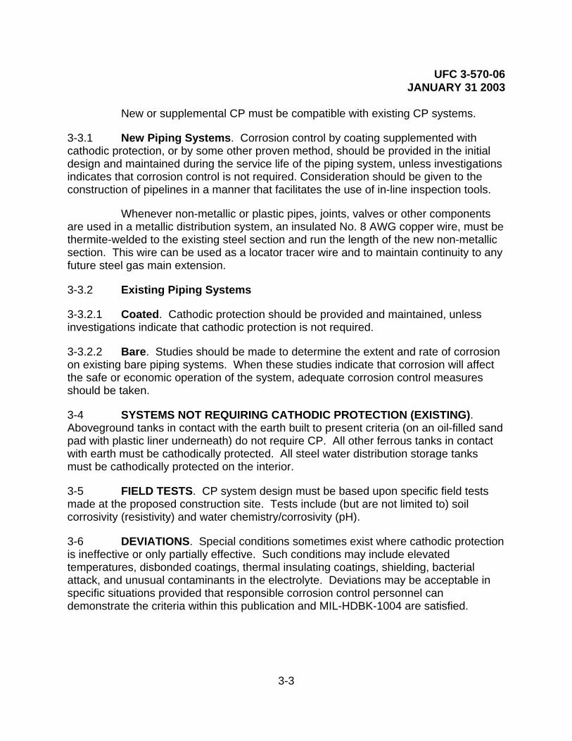
UFC 3-570-06 JANUARY 31 2003
3-3
New or supplemental CP must be compatible with existing CP systems.
3-3.1 New Piping Systems. Corrosion control by coating supplemented with cathodic protection, or by some other proven method, should be provided in the initial design and maintained during the service life of the piping system, unless investigations indicates that corrosion control is not required. Consideration should be given to the construction of pipelines in a manner that facilitates the use of in-line inspection tools.
Whenever non-metallic or plastic pipes, joints, valves or other components are used in a metallic distribution system, an insulated No. 8 AWG copper wire, must be thermite-welded to the existing steel section and run the length of the new non-metallic section. This wire can be used as a locator tracer wire and to maintain continuity to any future steel gas main extension.
3-3.2 Existing Piping Systems
3-3.2.1 Coated. Cathodic protection should be provided and maintained, unless investigations indicate that cathodic protection is not required.
3-3.2.2 Bare. Studies should be made to determine the extent and rate of corrosion on existing bare piping systems. When these studies indicate that corrosion will affect the safe or economic operation of the system, adequate corrosion control measures should be taken.
3-4 SYSTEMS NOT REQUIRING CATHODIC PROTECTION (EXISTING). Aboveground tanks in contact with the earth built to present criteria (on an oil-filled sand pad with plastic liner underneath) do not require CP. All other ferrous tanks in contact with earth must be cathodically protected. All steel water distribution storage tanks must be cathodically protected on the interior.
3-5 FIELD TESTS. CP system design must be based upon specific field tests made at the proposed construction site. Tests include (but are not limited to) soil corrosivity (resistivity) and water chemistry/corrosivity (pH).
3-6 DEVIATIONS. Special conditions sometimes exist where cathodic protection is ineffective or only partially effective. Such conditions may include elevated temperatures, disbonded coatings, thermal insulating coatings, shielding, bacterial attack, and unusual contaminants in the electrolyte. Deviations may be acceptable in specific situations provided that responsible corrosion control personnel can demonstrate the criteria within this publication and MIL-HDBK-1004 are satisfied.
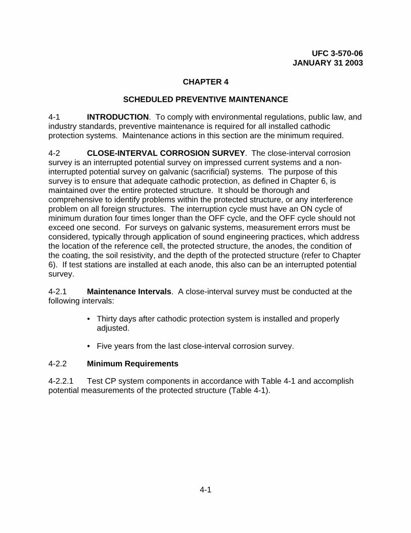
UFC 3-570-06 JANUARY 31 2003
4-1
CHAPTER 4
SCHEDULED PREVENTIVE MAINTENANCE
4-1 INTRODUCTION. To comply with environmental regulations, public law, and industry standards, preventive maintenance is required for all installed cathodic protection systems. Maintenance actions in this section are the minimum required.
4-2 CLOSE-INTERVAL CORROSION SURVEY. The close-interval corrosion survey is an interrupted potential survey on impressed current systems and a non-interrupted potential survey on galvanic (sacrificial) systems. The purpose of this survey is to ensure that adequate cathodic protection, as defined in Chapter 6, is maintained over the entire protected structure. It should be thorough and comprehensive to identify problems within the protected structure, or any interference problem on all foreign structures. The interruption cycle must have an ON cycle of minimum duration four times longer than the OFF cycle, and the OFF cycle should not exceed one second. For surveys on galvanic systems, measurement errors must be considered, typically through application of sound engineering practices, which address the location of the reference cell, the protected structure, the anodes, the condition of the coating, the soil resistivity, and the depth of the protected structure (refer to Chapter 6). If test stations are installed at each anode, this also can be an interrupted potential survey.
4-2.1 Maintenance Intervals. A close-interval survey must be conducted at the following intervals:
• Thirty days after cathodic protection system is installed and properly adjusted.
• Five years from the last close-interval corrosion survey.
4-2.2 Minimum Requirements
4-2.2.1 Test CP system components in accordance with Table 4-1 and accomplish potential measurements of the protected structure (Table 4-1).

UFC 3-570-06 JANUARY 31 2003
4-2
Table 4-1. Close-Interval Survey CP System Component Testing Requirements
CP SYSTEM TYPE TEST MEASUREMENT
GALVANIC (SACRIFICIAL) SYSTEMS (at each test station)
a) One anode-to-soil potential measurement with the reference electrode placed over the anode, and the anode lead disconnected.
b) Anode-to-structure current using (in order of preference) a clamp-on milliammeter, a multimeter measuring millivolts across a calibrated shunt, or a multimeter connected in series measuring milliamperes.
IMPRESSED CURRENT SYSTEMS
a) Perform the rectifier operational checkout (para 4-5).
b) Calculate the rectifier efficiency by dividing the calculated output DC power by the factored input AC power.
c) Perform the impressed current anode bed survey (para 4-6).

UFC 3-570-06 JANUARY 31 2003
4-3
Table 4-2. Close-Interval Survey Potential Measurement Locations
STRUCTURE TYPE POTENTIAL MEASUREMENT LOCATIONS
PIPELINES Locate the reference cell over the pipeline at intervals not to exceed the depth of the pipeline, normally every (1 to 1.5 meters (3 to 5 feet).
ON GRADE STORAGE TANKS
Locate the reference cell: Next to the tank every 1.8 meters (6 feet) around the tank circumference. At a distance one tank radius away from the tank at eight equally spaced locations around the tank circumference.
UNDERGROUND STORAGE TANKS
Locate the reference cell: Every 1 meter (3 feet) over the tank. At least every 1M over feed and return piping. Over the manhole, fill pipe, and vent pipe. Over all metallic structures in the area if readings indicate an isolated system is shorted to a foreign structure.
ISOLATED STRUCTURES
Take one structure-to-electrolyte (S/E) potential measurement on each side of all dielectric couplings without moving the reference electrode.
Note: If the potential difference between measurements on each side of a dielectric coupling is < 10 millivolts, verify its integrity using an isolation flange tester
ALL STRUCTURES WITH FOREIGN LINE CROSSINGS
Locate the reference cell: Over the foreign line at all points where it crosses the protected structure. Over the foreign line where it passes near the anode bed.
ALL STRUCTURES WITH CASED CROSSINGS
Locate the reference cell: Over each end of the casing on all casings.
Note: If the casing is shorted or partially shorted to the pipeline, and the potentials over the pipeline are depressed below criteria described in Chapter 6, take immediate action to clear the short.
ALL STRUCTURES IN SOIL
Annotate the soil condition for comparison of past/future potential and current measurements.

UFC 3-570-06 JANUARY 31 2003
4-4
4-2.2.2 Review all potential readings. Annotate the low potential measurements, the high potential measurements, and other significant potential measurements to re-evaluate those locations when performing the corrosion survey.
4-2.2.3 If the data taken show that the current output is not sufficient to satisfy the criteria in Chapter 6, adjust or supplement the system as necessary. After 30 days, perform a corrosion survey for those locations identified in paragraph 4-3.
4-3 CORROSION SURVEY. The corrosion survey is conducted to ensure adequate cathodic protection still exists as proven on the last close-interval corrosion survey. The procedures are the same as the close-interval corrosion survey, with different minimum requirements for the potential measurements. The close-interval corrosion survey data should be used to determine where potential measurements must be taken to reasonably ensure that the criteria of cathodic protection are being met for the entire structure being protected and no interference problems exist on any foreign structures.
4-3.1 Maintenance Interval. A corrosion survey must be conducted at the following intervals:
• Thirty days after major modification to the cathodic protection system or the protected structure.
• After any corrosion leak on the protected structure.
• After any inspection or survey which indicates that the current requirement of the last corrosion survey are not valid (low or high potential measurements at the proper current output level).
• One year from last close-interval corrosion survey or corrosion survey which satisfied the criteria in Chapter 6.
4-3.2 Minimum Requirements
4-3.2.1 Using data from the most recent close-interval corrosion survey, or using sound engineering practices, choose a sufficient number of locations for potential testing to ensure the entire structure has adequate cathodic protection (for criteria, refer to Chapter 6). Test CP system components in accordance with Table 4-3. Table 4-4 presents requirements for potential testing of the protected structure.

UFC 3-570-06 JANUARY 31 2003
4-5
Table 4-3. Corrosion Survey Component Testing
CP SYSTEM TYPE TEST MEASUREMENT
GALVANIC SYSTEMS
(at each test station)
a) One S/E potential measurement with the reference electrode placed directly over/adjacent to the protected structure at the location(s) nearest the anode(s).
b) One S/E potential measurement with the reference electrode placed directly over/adjacent to the protected structure midway between anode(s).
c) One anode-to-electrolyte potential measurement with the reference electrode placed directly over/adjacent to the anode with the anode lead disconnected.
d) Anode-to-structure current using (in order of preference) a clamp-on milliammeter, a multimeter measuring millivolts across a calibrated shunt, or a multimeter connected in series measuring milliamperes.
IMPRESSED CURRENT SYSTEMS
Perform the rectifier operational checkout (paragraph 4-5).
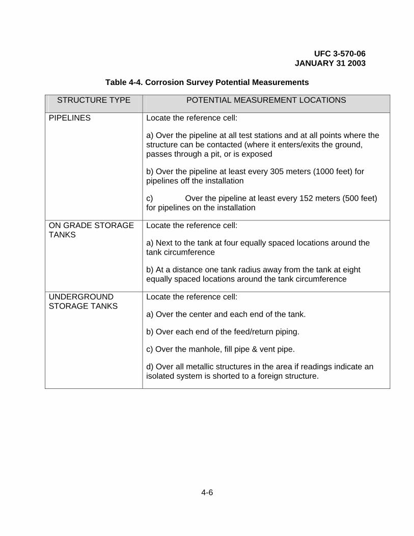
UFC 3-570-06 JANUARY 31 2003
4-6
Table 4-4. Corrosion Survey Potential Measurements
STRUCTURE TYPE POTENTIAL MEASUREMENT LOCATIONS
PIPELINES Locate the reference cell:
a) Over the pipeline at all test stations and at all points where the structure can be contacted (where it enters/exits the ground, passes through a pit, or is exposed
b) Over the pipeline at least every 305 meters (1000 feet) for pipelines off the installation
c) Over the pipeline at least every 152 meters (500 feet) for pipelines on the installation
ON GRADE STORAGE TANKS
Locate the reference cell:
a) Next to the tank at four equally spaced locations around the tank circumference
b) At a distance one tank radius away from the tank at eight equally spaced locations around the tank circumference
UNDERGROUND STORAGE TANKS
Locate the reference cell:
a) Over the center and each end of the tank.
b) Over each end of the feed/return piping.
c) Over the manhole, fill pipe & vent pipe.
d) Over all metallic structures in the area if readings indicate an isolated system is shorted to a foreign structure.

UFC 3-570-06 JANUARY 31 2003
4-7
Table 4-4. Corrosion Survey Potential Measurements (Continued)
STRUCTURE TYPE POTENTIAL MEASUREMENT LOCATIONS
ISOLATED STRUCTURES
Take one structure-to-electrolyte (S/E) potential measurement on each side of all dielectric couplings without moving the reference electrode.
Note: If the potential difference between measurements on each side of a dielectric coupling is less than 10 millivolts, verify its integrity using an isolation flange tester.
ALL STRUCTURES WITH FOREIGN LINE CROSSINGS
Locate the reference cell:
a) Over the foreign line at all points where it crosses the protected structure.
b) Over the foreign line where it passes near by the anode bed.
ALL STRUCTURES WITH CASED CROSSINGS
Locate the reference cell:
a) Over the protected structure on each side of all casings.
b) Over each end of the casing on all casings.
Note: If the casing is shorted or partially shorted to the pipeline, and the potentials over the pipeline are depressed below criteria described in Chapter 6, take immediate action to clear the short.
WATERFRONT STRUCTURES
At all permanent reference electrodes. Also,
locate portable reference cells:
a) Adjacent to the structure at all test stations.
b) Every 46 meters (150 feet) along a continuous length of sheet pile wall at both the surface and at the bottom.
c) At other test points identified in maintenance manuals or past surveys.
OTHER STRUCTURES Locate the reference cell at test points identified in the maintenance manual or other past surveys.
ALL STRUCTURES Annotate the soil condition (or tide level for waterfront structures) for comparison to past and future measurements.

UFC 3-570-06 JANUARY 31 2003
4-8
4-3.2.2 Review all potential readings. Annotate the three lowest potential measurements and the highest potential measurement to re-evaluate those specific locations when performing the impressed current system check.
4-3.2.3 For all structures, compare the potential measurements to those previously taken at the same locations to identify changes.
4-3.2.4 If the potential measurements reveal current output does not satisfy criteria in Chapter 6, adjust or supplement the system as necessary. After 30 days, accomplish the survey again (paragraph 4-3.1).
4-4 WATER TANK CALIBRATION. The water tank calibration is a comprehensive and thorough survey to ensure that cathodic protection is maintained over the entire surface of the tank to be protected in accordance with Chapter 6 criteria, and there are no excessive voltages on any part of the tank interior that could damage the coating. Water tank calibration comprises an interrupted potential survey on impressed current systems and a non-interrupted potential survey on galvanic systems. The interruption cycle must have an ON cycle that is a minimum of four times longer than the OFF cycle where the OFF cycle is normally one second. On a galvanic system, measurement errors must be accounted for using sound engineering practices, including reference cell placement, anode positions, and coating condition. If the system design permits, this may also include an interrupted potential survey.
4-4.1 Maintenance Intervals. Recommended intervals for conducting water tank calibrations are:
• Thirty days after the cathodic protection system is installed, modified, or adjusted.
• One year from the last water tank calibration.
4-4.2 Minimum Requirements
4-4.2.1. Inspect water tanks in accordance with Tables 4-5 and 4-6.

UFC 3-570-06 JANUARY 31 2003
4-9
Table 4-5. Water Tank Calibration CP System Component Tests
CP SYSTEM TYPE TEST MEASUREMENT
GALVANIC SYSTEMS
Measure anode-to-structure current using (in order of preference) a clamp-on milliammeter, a multimeter measuring millivolts across a calibrated shunt, or a multimeter connected in series measuring milliamperes.
IMPRESSED CURRENT SYSTEMS
a) Perform the rectifier operational checkout (paragraph 4-5).
b) Calculate the rectifier efficiency by dividing the calculated output DC power by the factored input AC power.
Table 4-6. Water Tank Calibration Potential Measurements
STRUCTURE TYPE POTENTIAL MEASUREMENT LOCATIONS
TANK WALLS
Position the reference cell near the water surface, at mid-depth and at the bottom in the following locations:
a) Next to the tank wall directly adjacent to each anode string.
b) Next to the tank wall midway between two adjacent anode strings.
TANK BOTTOM Locate the reference cell:
a) Two inches above the tank bottom directly beneath each anode string.
b) Two inches above the tank bottom and as far away from the anode strings as possible.
METALLIC RISER (Elevated Water Tanks)
Locate the reference electrode adjacent to the riser wall at intervals of 1.5 meters (5 feet) from the top to the bottom of the riser.
PERMANENT REFERENCE CELLS
Measure and compare the potential of each permanent cell to a portable reference cell to determine its accuracy.
ALL TANKS Annotate the water level for comparison to past and future measurements.
4-4.2.2 For all tanks, compare potential measurements to measurements previously

UFC 3-570-06 JANUARY 31 2003
4-10
taken at the same locations to determine if changes have occurred.
4-4.2.3 If potential measurements do not satisfy Chapter 6 criteria and the current output meets the current requirement from the last survey, adjust or supplement the system as necessary. After 30 days, perform a water tank calibration (refer to paragraph 4-4).
4-5 RECTIFIER OPERATIONAL INSPECTION. The purpose of the rectifier operational inspection is to determine the serviceability of all components required to impress current to the anodes of the impressed current system. The inspection should be thorough to ensure dependable current until the next inspection.
4-5.1 Maintenance Intervals. This checkout should be accomplished together with the close-interval corrosion survey, the corrosion survey, the water tank calibration, or when any inspection or survey indicates that problems with the rectifier may exist.
4-5.2 Minimum Requirements
4-5.2.1 Visually check all rectifier components, shunt box components, safety switches, circuit breakers, and other system power components.
4-5.2.2 Tighten all accessible connections and check temperature of all the components listed in 4-5.2.1.
4-5.2.3 Using a dependable hand-held meter, measure the output voltage and current, and calibrate the rectifier meters, if present.
4-5.2.4 For rectifiers with more than one circuit, measure the output voltage and current for each circuit using a dependable hand-held meter, and calibrate the rectifier meters, if present.
4-5.2.5 For rectifiers with potential voltmeters, using a dependable hand-held meter, measure the potentials for each voltmeter, and calibrate that rectifier meter. Using a known good reference electrode, measure the potential difference to the installed permanent reference electrode by placing both electrodes together in the electrolyte with CP current off. If the difference is more than 10 mV, replace the permanent reference electrode.
4-5.2.6 Calculate the cathodic protection system circuit resistance of each circuit by dividing the rectifier DC voltage output of each circuit by the rectifier DC ampere output for that circuit.
4-5.2.7 For all close-interval corrosion surveys, or if otherwise required, calculate the rectifier efficiency. This also includes timing the revolutions of the kWh meter and annotating the meter factor from the face of the kWh meter (refer to Chapter 5 for

UFC 3-570-06 JANUARY 31 2003
4-11
procedures).
4-6 IMPRESSED CURRENT ANODE BED. The impressed current anode bed survey is a non-interrupted survey of the ground bed to determine the condition of the anodes. It should be comprehensive and thorough to identify any possible problem with the impressed current anodes. It may also be used to predict failure and to program replacement. This survey would normally be done together with the close-interval corrosion survey.
As a minimum, an impressed current anode bed survey should include ON potential over-the-anodes at intervals described in Table 4-7, unless the system has incorporated other means for monitoring the anodes (e.g., individual anode leads in an anode junction box).
Table 4-7. Recommended Over-the-Anode Intervals for the Impressed Current Anode Bed Survey
CP SYSTEM TYPE TEST MEASUREMENT
REMOTE SHALLOW ANODE GROUND BEDS
a) Measure anode-to-soil potentials at 0.6-meter (2-foot) intervals along the length of the anode bed, beginning 3 meters (10 feet) before the first anode, and ending 3 meters past the last anode in the ground bed.
b) Plot test results on graph paper to give a visual indication of the anode bed condition.
DISTRIBUTED SHALLOW ANODE GROUND BEDS
Measure one anode-to-soil potential with the reference cell located directly over each anode.
DEEP ANODE GROUNDBEDS
a) In lieu of anode potential measurements, measure anode circuit current using (in order of preference) a clamp-on milliammeter, a multimeter measuring millivolts across a calibrated shunt, or a multimeter connected in series measuring milliamperes.
b) Measure the anode current for each anode if separate leads are available.
4-7 IMPRESSED CURRENT SYSTEM CHECK. The impressed current system check is an operational check of the impressed current system to ensure the system is
UFC 3-570-06 JANUARY 31 2003
4-12
operating at the same level as the last close-interval corrosion survey or corrosion survey. This is a non-interrupted check and the potential measurements should be compared to previous ON cycle potential measurements. The locations for the potential measurements must be taken from the last close-interval corrosion survey, or corrosion survey, whichever is most recent, to reasonably ensure that the current output of the system is still being applied and is still sufficient.
4-7.1 Maintenance Intervals. The recommended period for conducting the impressed current system check is within 60 days of the last close-interval survey, corrosion survey, or impressed current system check. More frequent checks may be required by public law or local regulations.
Note: Underground storage tank CP rectifiers must be inspected at a frequency not exceeding 60 days to ensure compliance with regulations. Check with your state EPA authorities as state regulations may be more stringent or may impose additional requirements.
4-7.2 Minimum Requirements
4-7.2.1 Measure rectifier DC voltage and DC ampere outputs.
4-7.2.2 Ensure the DC ampere output of the rectifier meets the current (ampere) requirement found on the last close-interval or corrosion survey. If necessary, adjust the rectifier output, and measure outputs again. Repeat procedure as necessary.
4-7.2.3 Calculate the rectifier system circuit resistance by dividing the rectifier DC output voltage by the rectifier DC output current. If the rectifier has more than one circuit, calculate the resistance of each circuit.
4-7.2.4 Take S/E potential measurements at the locations of the three lowest and three highest potential measurements identified in the most recent close-interval or corrosion survey.
4-7.2.5 Compare the potential measurements to previous measurements at the same locations and determine if changes have occurred. If potential measurements do not satisfy criteria in Chapter 6, and the rectifier current output meets the current requirement from the last survey, adjust or supplement the CP system as necessary. Conduct a corrosion survey 30 days after adjustment or modification to the cathodic protection system.
4-8 GALVANIC ANODE CHECK. The galvanic anode system check is conducted to determine its operational condition. It is normally conducted as part of the close-interval survey, corrosion survey, or water tank calibration surveys described in paragraphs 4-2, 4-3, and 4-4.

UFC 3-570-06 JANUARY 31 2003
4-13
4-8.1 Procedure
4-8.1.1 Measure the potential of the structure with the reference electrode located directly over the structure, adjacent to an anode (structure-to-earth, DC volts).
4-8.1.2 Measure the potential of the structure with the reference electrode located directly over the structure, midway between anodes (remote structure-to-earth, DC volts). In this case, remote is as far as possible from the anodes, directly over the protected structure.
4-8.1.3 Disconnect the anode lead from the structure and measure potential of the anode with the reference electrode located directly over the anode (anode-to-earth, DC volts).
4-8.1.4 Measure structure-to-anode current (anode output current, mA).
4-8.1.5 Compare measurements to those previously taken at the same location. Loss of anode-to-earth potential indicates a failed anode or failed anode lead. Loss of anode output current with stable anode-to-earth potential indicates consumption of the anode and pending failure. Loss of structure-to-earth potential with stable anode-to-earth potential and anode output current indicates loss of isolation.
4-9 RESISTANCE BOND CHECK. The resistance bond check is an operational check of two metallic structures connected with some type of semi-conductor or resistor, to ensure that the structures affected by the bond are maintained at proper levels and interference is mitigated. This bond may include reverse current switches, diodes, resistors, or other protective devices whose failures would jeopardize structure protection. These bonds may be between different sections of a protected structure, or may be between a protected structure and any other metallic structure (unprotected or protected with a different cathodic protection system). This is a non-interrupted check and the potential measurements should be compared to previous ON cycle potential measurements taken at the same locations. The locations for the potential measurements and meter connections must be the same and the operational status of any cathodic protection systems must be known.
4-9.1 Maintenance Interval. The recommended period for conducting the resistance bond check is within 60 days of the last check or immediately following failure of the CP system protecting either (or both) sides of the bond (unless immediate repair of the failure is possible). More frequent checks may be required by public law or local regulations.
4-9.2 Minimum Requirements
4-9.2.1 Measure rectifier DC voltage ampere output of the cathodic protection

UFC 3-570-06 JANUARY 31 2003
4-14
system on either (or both) sides of the resistance bond.
4-9.2.2 Measure the DC ampere current flow through the bond and annotate the direction of the current flow.
4-9.2.3 Measure potential of the metallic structures on both sides of the bond.
4-9.2.4 Evidence of proper functioning may be current output, normal power consumption, a signal indicating normal operation, or satisfactory cathodic protection levels on the structures, according to the function or design of the bond.
4-9.2.5 Compare measurements to measurements previously taken at the same locations to determine if changes have occurred.
4-9.2.6 If the potential measurements, current flow, current direction, or other measurement has changed from the last check, adjust or repair the component as necessary, and repeat the test of the bond.
4-10 LEAK SURVEY. The leak survey is a comprehensive, thorough survey to identify the cause of all leaks and the action required to prevent future leaks from occurring, or to reduce the leak rate.
4-10.1 Maintenance Interval. Leak surveys should be conducted after excavation, before backfilling of any leak on any pipeline or tank.
4-10.2 Minimum Requirements
4-10.2.1 Measure the pH of the soil where it contacts the pipeline or tank.
4-10.2.2 Measure the “as found” S/E potential of the pipe or tank where it contacts the soil. “As found” means before any adjustments of existing cathodic protection systems, addition of any form of cathodic protection, or installation of isolation or bonding components.
4-10.2.3 Determine the cause of the leak.
4-10.2.4 Evaluate the condition and determine appropriate repairs to the pipe or tank coating system.
4-10.2.5 Measure the “as left” S/E potential of the pipe or tank where it contacts the soil. “As left” means after all actions are taken to prevent future leaks. If these actions are taken after backfill operations, surface potentials are acceptable as described in Chapter 6.
4-10.2.6 If the leak survey determines the cause to be corrosion, determine the type

UFC 3-570-06 JANUARY 31 2003
4-15
of corrosion. Table 4-8 lists recommended corrective actions to prevent future leaks:
Table 4-8. Recommended Corrective Actions for Preventing Leaks
CP SYSTEM TYPE RECOMMENDED ACTION
STRUCTURE NOT CATHODICALLY PROTECTED
a) Take appropriate action to reduce the possibility of future leaks according to the type of corrosion found.
b) Determine the presence of interference, and if found, take action to mitigate interference corrosion.
c) Install isolation couplings, electrical continuity bonds, or cathodic protection as appropriate.
STRUCTURE CATHODICALLY PROTECTED
a) Troubleshoot, repair, or adjust existing CP system.
b) Supplement the existing CP system until protection is achieved, if necessary.
c) Conduct a corrosion survey of the system 30 days after any repairs, adjustments, or installations.
4-10.3 Galvanic Anode Systems. Galvanic anode systems are typically used in low resistivity soil, or on small or well-coated structures, or as “hot spot” protection on unprotected structures. Galvanic anodes may be easily installed before the backfill operation. Impressed current systems are typically used in high resistivity soil or on large or poorly coated structures. Also, consider bonding to an existing impressed current system.
4-11 RECORD KEEPING REQUIREMENTS. Historical records should be maintained of all surveys and inspections for the life of the protected structure. This is important for maintaining proof of cathodic protection and for a reference for troubleshooting or repair of the system.
Each CP system should have a folder with the following information on permanent file:
• Drawings of CP system from as-builts or other sources showing the location of all components.
• Drawings of the structure protected by the system showing all casings, foreign line crossings, test points, dielectrics, test stations or other

UFC 3-570-06 JANUARY 31 2003
4-16
pertinent information.
• Close-interval corrosion surveys and corrosion surveys (water tank calibration records for water tanks) conducted on the system.
• Rectifier operational checkout records (if impressed current system).
• Impressed current anode bed surveys (if impressed current system).
• Impressed current system checks (if impressed current system).
• Leak survey data records for the structure protected.
• Any other pertinent data of historical significance, such as anode drawings, anode data, manufacturer data, source of supply, anode types, rectifier data sheets, wiring diagrams, manufacturer’s data or manufacturer’s manual, contract information, in-house drawings, or life cycle estimates or information.

UFC 3-570-06 JANUARY 31 2003
5-1
CHAPTER 5
UNSCHEDULED MAINTENANCE REQUIREMENTS
5-1 INTRODUCTION. Impressed current cathodic protection systems require a higher level of maintenance than sacrificial (galvanic) CP systems. More things can, and do, go wrong. There are five major components to the operational impressed current system: the rectifier, the anode bed, the structure lead, the anode lead (header cable), and the structure. There are two major components to the operational sacrificial system: the anode and the structure lead. If adequate cathodic protection does not exist on the protected structure, then troubleshooting must be accomplished to determine the cause of this lack of protective current.
5-1.1 Troubleshooting. The starting point for all troubleshooting for impressed current systems is at the rectifier. Indications of all problems are present at this location. The greatest aids to troubleshooting are historical data and drawings of the system. Usually, the fault may be isolated, then verified by testing.
5-1.2 Procedures. For impressed current systems, there are sufficient test points on the face plate of the rectifier to isolate the faulty component. Follow the troubleshooting procedures in paragraph 5-2; the typical rectifier wiring diagram, Figure 5-2; the troubleshooting block diagram, Figure 5-1; the shunt multiplication factor, Figure 5-3; and the anode gradient samples, Figure 5-6. The starting point for all troubleshooting for galvanic systems is at the anode (or anode connection). For galvanic systems, there must be an anode test lead for conclusive testing of the anodes. For isolation of a fault to the major component, follow the troubleshooting procedures in paragraph 5-4.
5-2 TROUBLESHOOTING IMPRESSED CURRENT SYSTEMS
WARNING: All connections should be made with alligator clip leads with the rectifier circuit breaker or power switch OFF. If needlepoint leads are used with power ON, employ electrical safety practices for working with live circuits.
5-2.1 DC Voltage. Measure the DC voltage output of the rectifier with a handheld multimeter. With power ON, scale on DC volts, measure voltage from N4 to P4 (Figure 5-2). One of three conditions may exist: voltage may be near zero (proceed to paragraph 5-2.1.1), near half of normal (proceed to paragraph 5-2.1.2), or near normal (proceed to paragraph 5-2.1.3).
5-2.1.1 No DC voltage indicates that one of the components in the rectifier is faulty or there has been a loss of AC power (proceed to paragraph 5-2.5).
5-2.1.2 Half the normal voltage output indicates defective diodes/selenium plates

UFC 3-570-06 JANUARY 31 2003
5-2
or improper AC input. Proceed to paragraph 5-2.5 to check the AC input to the stacks and paragraph 5-2.7 to troubleshoot the diodes/selenium plates.
5-2.1.3 Normal DC voltage indicates a break in the anode lead, failed anodes, or a break in the structure lead (proceed to paragraph 5-2.). If the voltage is normal and the rectifier voltmeter reads significantly different, the connections or the voltmeter are faulty (proceed to paragraph 5-2.1.3a).
WARNING: AC voltage is still present inside the rectifier with the rectifier circuit breaker or power switch OFF. All connections inside the rectifier cabinet should be made with alligator clip leads connected with the power to the rectifier OFF. If needlepoint leads are used with power ON, use prudent electrical safety practices for working with live circuits. For Navy projects, when conducting work on or near circuits energized lines or parts of equipment operating at or above 50V, utilize work practices identified in OPNAV P-45-117-6-98.
Figure 5-1. Troubleshooting Block Diagram
DC Volts
DC Amps
1/2N
1/2N
0
0
N
Diode
0
Anode Bed
Anode Lead
Structure Lead
0
AC to Stacks
AC to Rectifier
N
AC
Taps
Action 1/2 N0
Near Zero Half Normal NormalTest
LEGEND
N
11.1
1.21.3
2 2.1
2.22.3
7
11
5.2
8
5
3
4
6
5.1
3.2
6.1 6.2
10
0
3.1
Ammeter Diode
7
Structure
9
12

UFC 3-570-06 JANUARY 31 2003
5-3
• With power OFF, check for loose connections from P2 to P3, N2 and N5 through N7, including any press-to-test switch or button, and continuity of all wires between those points. This will require disconnection of AC power from the rectifier cabinet and possibly removal of the rectifier from the cabinet. Note that loose connections are characterized by heat, discoloration of the connection, and melted insulation. Repair or replace loose connections and replace damaged or broken wires. If problems are not found, proceed with paragraph 5-2.1.3b.
• With power OFF, remove voltmeter from rectifier. This will require disconnection of AC power from the rectifier cabinet and possibly removal of the rectifier from the cabinet. Disconnect one end of the resistors on reverse side of meter. Measure the resistance of the resistors with a handheld multimeter on the ohms scale and compare to the value of the resistor (if no resistors are present, replace meter). Replace resistor or meter as required.

UFC 3-570-06 JANUARY 31 2003
5-4
Figure 5-2. Typical Rectifier Wiring Diagram
AC INPUTCB
A1A3 A2 A4
F5F4 F3 F2
F1F6
C1C2 C3 C4
C5C6
P2
P1
1 2
3 4
F7 C7
N8N9N3
N2 P2
N5
N7
N4
N6
P4
P3N10A V
NEGATIVE POSITIVE(ANODES)(STRUCTURE)
COARSETAPS
FINETAPS
STACKS
PRESSTO
READSWITCH
AMMETER VOLTMETER
SHUNT
TRANSFORMER
5-2.2 DC Current. Measure the DC current output of the rectifier with a handheld multimeter on the mV scale. Measure mV from N2 to N3. Multiply the indicated reading by the appropriate multiplication factor (Figure 5-3). One of three conditions may exist: the current may be near zero (proceed to paragraph 5-2.2.1), near half of normal (proceed to paragraph 5-2.2.2), or be near normal (proceed to paragraph 5-2.2.3).

UFC 3-570-06 JANUARY 31 2003
5-5
Figure 5-3. Shunt Multiplication Factors
50 mV
50 mV
50 mV
50 mV
50 mV
50 mV
50 mV
50 mV
50 mV
50 mV
50 mV
50 mV
SHUNT SIZE AMPS
75A
100A
50A
____mV X 2
1.5
1
____mV X
____mV X
____mV X45A .9
40A ____mV X
35A ____mV X
30A
25A
20A
15A
10A
5A
____mV X
____mV X
____mV X
____mV X
____mV X
____mV X
.8
.7
.6
.5
.4
.3
.2
.1
MEASURE X FACTOR =
____A
____A
____A
____A
____A
____A
____A
____A
____A
____A
____A
____A
=
=
=
=
=
=
=
=
=
=
=
=
a mV b A ____mV X ____A=____a MVb A
5-2.2.1 Normal DC voltage with near zero current indicates a break in the anode lead, failed anodes, or a break in the structure lead (proceed to paragraph 5-2.3).
5-2.2.2 Half the normal current output indicates either a defective diode/selenium plate; a break in the header cable between anodes; or, if there are multiple anode leads, loss of one anode lead or anode bed. Measure the DC voltage output of the rectifier with a handheld multimeter on the DC volts scale. Measure voltage from N4 to P4. If

UFC 3-570-06 JANUARY 31 2003
5-6
voltage is also half of normal, proceed to paragraph 5-2.7 to troubleshoot the diodes/selenium plates. If voltage is normal, proceed to paragraph 5-2.8 to troubleshoot the anode bed.
5-2.2.3 If the current is normal and the rectifier ammeter reads significantly different, either the shunt, the connections, or the ammeter is faulty (proceed to paragraph 5-2.2.3a). If the current is normal, the rectifier ammeter reads normal, and structure potentials are still significantly changed from normal, proceed to paragraph 5-2.2.3d.
a) Measure the DC current with a handheld multimeter connected in series and with the meter on the DC amps scale. Disconnect anode header cable at P4 and measure current from P4 to anode lead. Compare the measured current value to the current value taken in paragraph 5-2.2. If values are significantly different, replace the shunt. If values are the same, proceed with paragraph 5-2.2.3b.
WARNING: AC voltage is still present inside the rectifier with the rectifier circuit breaker or power switch OFF. All connections inside the rectifier cabinet should be made with alligator clip leads connected with the power to the rectifier OFF. If needlepoint leads are used with power ON, observe prudent electrical safety practices for working with live circuits.
b) With power OFF, check for loose connections from N2 through N9, including any press-to-test switch or button, and continuity of all wires between those points. This will require disconnection of AC power from the rectifier cabinet and possibly removal of the rectifier from the cabinet. Note that loose connections are characterized by heat, discoloration of the connection, and melted insulation. Repair or replace loose connections and replace damaged or broken wires. If problems are not found, proceed with paragraph 5-2.2.3c.
c) With power OFF, remove ammeter from rectifier. This will require disconnection of AC power from the rectifier cabinet and possibly removal of the rectifier from the cabinet. Disconnect one end of the resistors on reverse side of meter. Measure the resistance of the resistors with a handheld multimeter on the ohms scale and compare to the value of the resistor (if no resistors are present, replace meter). Replace resistor or meter as required.
d) Normal current values accompanied by loss of potential shifts indicate a change in the protected structure. If the protected structure is isolated, check all dielectrics and repair or replace faulty ones. If the protected structure is not isolated, check for additions to the protected structure, or new structures in the area which are continuous with the protected structure, increase current to protect larger structure(s), isolate other structure(s), or install additional impressed current system(s) as required.
UFC 3-570-06 JANUARY 31 2003
5-7
5-2.3 Anode Lead Wires. With power OFF, disconnect anode lead(s) at P4. Using an alternative isolated metallic structure (isolated from structure being tested; if doubt exists, measure continuity to structure lead), such as a metal culvert or fence, or install temporary ground rods, and connect to P4 (positive terminal). For a short period of time, turn power ON and note AC current (paragraph 5-2.2). One of two conditions exists: either current is now present (changed); or it is not present (not changed).
Note: If the structure being tested is the inside of a water tank or tower, and the lack of water will not allow current flow (no electrolyte), fill the tank, and then retest.
5-2.3.1 Current is Present. If current exists, the anode lead is broken or the anodes have failed (proceed to paragraph 5-2.8).
5-2.3.2 Current is Not Present. If no current exists, the structure lead may be broken (proceed to paragraph 5-2.4).
5-2.4 Structure Lead. For this test, the temporary or alternative anode should remain connected to terminal P4 as described previously in paragraph 5-2.3. With power OFF, disconnect structure lead at N4. Using an alternative isolated metallic structure (isolated from structure being tested, if doubt exists, measure continuity to structure lead), such as a metal culvert or fence, or install temporary ground rods, and connect to N4 (negative terminal). For a short period of time, turn power ON and note AC current (paragraph 5-2.1). One of two conditions exist, either current is now present (changed) (proceed to paragraph 5-2.4.1); or it is not present (not changed) (proceed to paragraph 5-2.4.2).
5-2.4.1 Since current is now present, the structure connection is broken. Use the fault detector and cable locator, connected directly to the structure lead at N4, to trace the structure lead from the rectifier towards the structure. This can be extremely difficult in some cases. An alternative method is to locate the first structure connection (from drawings, markers, or induction methods). Excavate to the structure and measure continuity back to the rectifier using a cathodic protection multi-combination meter continuity check circuit. Use the fault detector and cable locator, connected directly to the structure lead, to trace the lead from the structure towards the rectifier. If this is still unsuccessful, replace the structure lead from the rectifier to the structure.
Note: When using the direct connection method, it is essential to have a low-resistance isolated ground for the fault detector or cable locator to put a strong locator signal on the cable under test.
5-2.4.2 If current still does not exist (not changed), the temporary anode bed is not sufficient. Supplement the temporary anode bed, then repeat paragraph 5-2.3.
5-2.5 AC Voltage to Stacks. Measure the AC voltage input to the stacks of the

UFC 3-570-06 JANUARY 31 2003
5-8
rectifier with a handheld multimeter on the AC volts scale. Measure voltage from F6 to C6 (tap bars). One of two conditions may exist: voltage may be near zero (proceed to paragraph 5-2.5.1), or near normal (proceed to paragraph 5-2.5.2).
5-2.5.1 Voltage Near Zero. This indicates loss of AC power to the rectifier, bad fuses or circuit breakers, or a bad transformer (or connections) in the rectifier (proceed to paragraph 5-2.6).
5-2.5.2 Voltage Near Normal. This indicates faulty diodes/selenium plates or bad connections inside the rectifier (proceed to paragraph 5-2.7). If the rectifier does not have taps, proceed to paragraph 5-2.6; if that test is normal, the rectifier must be removed from the cabinet for checkout. Refer to specific rectifier manual to troubleshoot the diodes/selenium plates and the transformer. For general reference, see paragraph 5-2.7 for the stacks and paragraph 5-2.9 for the transformer.
5-2.6 Fuses. Check all fuses and measure AC voltage input to the rectifier. With power OFF, remove all fuses at the rectifier and any fusible disconnect. Measure the continuity of fuses with a handheld multimeter. Set scale to ohms; measure resistance of each fuse. Corrosion on fuse end caps or fuse holders will also cause loss of voltage. Replace any fuse with measurable resistance, or clean and reinstall fuses if corrosion is found. If a disconnect exists, measure the AC voltage with a handheld multimeter on the AC volts scale. Measure the voltage on the rectifier side of the disconnect. If a disconnect does not exist, measure the AC voltage from the circuit breaker of the rectifier with a handheld multimeter on AC volts scale. For 110/120 volt, single-phase rectifiers turn power to the rectifier OFF, open cabinet and connect meter to A3 (output of circuit breaker) and ground (cabinet). Turn power to the rectifier ON and the rectifier circuit breaker ON; measure voltage from the rectifier circuit breaker. For 220/240 volt, single-phase rectifiers, use the same procedures, but connect meter to A4 and (instead of cabinet ground) the output side of the circuit breaker on the second power lead (not shown on drawing). If voltage is present, proceed to paragraph 5-2.6.1. If voltage is not present, proceed to paragraph 5-2.6.2.
5-2.6.1 Voltage is Present. This indicates either the transformer or the connections inside the rectifier are faulty (proceed to paragraph 5-2.9).
5-2.6.2 Voltage is Not Present. This indicates loss of AC Power to the rectifier. Measure the AC voltage to the circuit breaker of the rectifier with a handheld multimeter on the AC volt scale. For 110/120 volt, single-phase rectifiers turn power to the rectifier OFF, open cabinet and connect meter to A1 and A4. Turn power to the rectifier ON; measure voltage to rectifier. For 220/240 volt, single-phase rectifiers, use the same procedures, but connect meter to A4 and input side of the circuit breaker (A1) on the second power lead (not shown on drawing). If voltage is not present, proceed to paragraph 5-2.10; or if voltage is present, replace circuit breaker or fuse.

UFC 3-570-06 JANUARY 31 2003
5-9
5-2.7 Diodes. Check the diodes/selenium plates of the rectifier with a handheld multimeter on the diode check scale. With power OFF, remove the tap bars or shorting wires and the anode lead (P4) and/or the structure lead (N4). Check the diode/selenium plate sets by connecting one test lead to N4 and the other to F6 (diode 3), then to C6 (diode 4). Both should beep or not beep. Reverse test leads and repeat connections. The beep should be opposite (both should not beep or beep). Repeat the test using P4 instead of N4 to test diodes/selenium plate sets (diodes 1 and 2).
Note: An ohms scale may be used. A good diode has very high resistance in one direction and low resistance in the other direction.
With power OFF, check for loose connections from F6 to F7, C6 to C7, P1 to P2, P2 to P4, and N1 through N4, and continuity of all wires between those points. Repair or replace loose connections and replace damaged or broken wires, if possible. If no problems are found, replace the stacks.
5-2.8 Anode Bed. Before a great deal of time is expended troubleshooting an anode bed, it should be determined from records if there is sufficient anode material to attempt locating and repairing the fault. Generally, if the current and time is calculated to amp years, comparing that number to the weight of the installed anodes and the weight loss of the anode material will indicate if the anodes are expended or have significant life remaining. Another indicator is if a gradual failure occurred over a period of time, the anodes have failed. If the failure was sudden, a cable break can be expected. If failed anodes are found, replace the anode bed. If a broken anode lead is found, repair the cable. The first step to locating the break is to find the location of any excavations that have occurred in the area of the anode cable. There are two methods of troubleshooting anode beds, depending upon whether all anodes have failed (no current), or some (or most) of the anodes have failed. If one or more anodes are functioning, see paragraph 5-2.8.1. If no anodes are functioning, see paragraph 5-2.8.2.
5-2.8.1 If one or more anodes are functioning, the best method is first to locate the functioning anodes, then an anode bed gradient graph to isolate and locate the problem.
Note: If separate anode lead wires in a junction box were installed, use these to measure the anode current and determine the functioning anodes.
Perform a close interval survey over the anode bed. For the purpose of troubleshooting, you may adjust the rectifier to the highest voltage setting that would not result in coating damage to the structure, to allow easier location of the anodes. Measure the potentials over the anodes with a handheld multimeter on the DC volts scale. With power ON, connect the positive lead of the multimeter to the structure lead (N4) of the rectifier. Using a copper/copper sulfate reference cell connected to the

UFC 3-570-06 JANUARY 31 2003
5-10
negative lead of the multimeter, locate the point of highest voltage on the surface of the ground (this will be directly over an anode). Repeat by locating all operational anodes. Mark each anode found and compare to system drawings. Starting in a straight line 3 meters (10 feet) from the first anode, perform a potential test every 0.6 meters (two feet) over the entire length of the anode bed, to a point 3 meters (10 feet) past where the last anode is (or is suppose to be) located. Using graph paper, and using vertical lines to represent the measured potentials, and horizontal lines to represent the 0.6-meter (two-foot) intervals, graph all readings. This will show the condition of all anodes, and will indicate if a broken header cable (anode lead) or failed anodes exist. It will show a broken cable between functional and non-functional anodes. If anodes are failing, the gradients will peak differently, or the gradients will fall, then rise intermittently.
5-2.8.2 If no anodes are operational, use the fault detector and cable locator, connected directly to the anode cable P4, to trace the anode lead from the rectifier towards the anode bed. This can be extremely difficult in some cases. An alternative method is to locate the first anode (from drawings, markers, or induction methods). Excavate to the first anode and measure continuity back to the rectifier using a cathodic protection Multi-Combination meter continuity check circuit. Use the fault detector and cable locator, connected directly to the anode to trace the anode lead from the anode towards the rectifier. If this is still unsuccessful, replace the anode lead from the rectifier to the anode.
Note: When using the direct connection method, it is essential to have a low-resistance isolated ground for the fault detector or cable locator to put a strong locator signal on the cable under test.
5-2.9 Rectifier Taps. Measure the AC voltage on the taps of the rectifier with a handheld multimeter on the AC volt scale. Remove the tap bars or shorting wires. Measure the voltage from F5 to F4, F4 to F3, F3 to F2, F2 to F1, and F1 to C1. All readings should be approximately the same. Measure the voltage from C5 to C4, C4 to C3, C3 to C2, C2 to C1. All readings should be approximately the same. Any lead that tests different must be checked for connection (proceed to paragraph 5-2.9.1).
Note: On some rectifiers, F1 to C1 may be a unique voltage.
5-2.9.1 With power OFF, check for loose connections from F1 through F5 and C1 through C5, including any tap bar or shorting wire, and continuity of all wires between those points. Note that loose connections are characterized by heat, discoloration of the connection, and melted insulation. Repair or replace loose connections and replace damaged or broken wires, if possible. If only one tap is inoperative, a different tap setting may be operational, and testing will reveal functioning taps. If replacement of wire is not possible, replace the transformer. If no problems are found, proceed with 5-2.9.2.

UFC 3-570-06 JANUARY 31 2003
5-11
5-2.9.2 With power OFF, check for loose connections from A2 through A4 and continuity of all wires between those points. Repair or replace loose connections and replace damaged or broken wires, if possible. If replacement of wire is not possible, replace the transformer.
Note: Checkout of transformers or pole fuses require personnel certified for work on high voltage lines and proper equipment beyond the scope of these procedures.
5-2.10 Rectifier Input Voltage. First verify that the circuit breaker has not tripped or the fuse has not blown. If properly operating, measure the AC voltage from the circuit breaker or fuse where power is supplied to the rectifier with a handheld multimeter on the AC volts scale. For 110/120 volt, single-phase systems, open the circuit breaker panel or fuse panel and connect meter to the output of circuit breaker or the output side of the fuse (not shown on drawing) and ground or neutral bar. For 220/240 volt, single-phase systems, use the same procedures, but connect the meter to the output lugs of the circuit breakers or the output side of the fuses. If voltage is not present, proceed to paragraph 5-2.10.1. If voltage is present, locate the break in the power feed from that point to the rectifier circuit breaker (or rectifier fusible disconnect, whichever was last tested).
5-2.10.1. Measure the AC voltage to the circuit breaker or fuse supplying power to the rectifier with a handheld multimeter on the AC volt scale. For 110/120 volt, single-phase systems open the circuit breaker panel or fuse panel and connect the meter to the main lugs of the circuit breaker panel or the input side of the fuses (not shown on drawing) and ground. For 220/240 volt, single-phase systems, use the same procedures, but check individual legs separately. If voltage is not present, locate the circuit breaker panel or transformer supplying power to the panel and repeat paragraph 5-2.10; if voltage is present, replace the circuit breaker or fuses.
5-3 IMPRESSED CURRENT SYSTEM COMMON PROBLEMS. Table 5-1 lists common problems associated with impressed current cathodic protection systems and the symptoms of these problems.

UFC 3-570-06 JANUARY 31 2003
5-12
Table 5-1. Common Impressed Current Rectifier Problems
SYMPTOM POSSIBLE CAUSE REFERENCE PARAGRAPH
Broken anode lead (header cable)
5-2.3 Zero output current and slight increase in output voltage. Historical data indicates that output has remained relatively constant for a long period of time.
Broken structure lead 5-2.4
Zero output current and maximum output voltage. Historical data shows that system voltage increased several times and output current decreased slowly at first, then faster as time progressed
Failed anode bed
Loss of AC power 5-2.6/5-2.10 Defective meters 5-2.1.2/5-2.2.3 Broken anode or structure leads
5-2.3/5-2.4
Blown fuses or tripped circuit breakers
5-2.6/5-2.10
Defective lightning arrester Defective stacks or transformer
5-2.7/5-2.8
Zero output current and/or zero or minimal output voltage. No historical data immediately available
Loose or bad wire connections
5-2.7/5-2.8
Lightning or other power surges
5-2.6/5-2.10
Electrical short circuits 5-2.6
Blown fuses or tripped circuit breakers.
Sudden decrease in soil resistivity (long period of heavy rain)
5-2.6
Rectifier voltage suddenly about half of normal. Rectifier output required to be turned up to regain proper amount of current.
Rectifier is half waving. One of the diodes or selenium plates burned out.
5-2.1
Rectifier output current decreased, but voltage near normal.
Failure of some anodes or anode leads. Soil dried out (increase resistivity)
5-2.2

UFC 3-570-06 JANUARY 31 2003
5-13
5-4 TROUBLESHOOTING GALVANIC (SACRIFICIAL) CATHODIC PROTECTION SYSTEMS. Galvanic cathodic protection is inherently maintenance-free. The current is merely a result of the potential difference of the two metals. Recurring maintenance checks are performed to ensure continued satisfactory performance. Galvanic anodes sacrifice themselves to protect the structure. They normally consume themselves at a constant rate and failure can be predicted by current measurement versus time.
5-4.1 Common Problems. The most common problem in sacrificial anode systems are shorts around or failure of dielectrics on isolated protected structures. Due to the very limited voltage, sacrificial anodes usually cannot supply sufficient current to protect the structures if isolation is lost. On well-coated structures, the contact resistance to earth is high. Other metals in the earth that are not coated have a very low contact resistance, providing a low resistance path for anode current. Maintaining the dielectrics in an isolated system is essential to continued satisfactory performance of sacrificial anode systems. See paragraph 7-7 for detailed procedures to locate failed dielectrics. One failed dielectric can result in loss of protection for the entire system.
5-4.2 Lead Wires. Failure of the anode lead wires is uncommon, since copper exposed by nicks or insulation defects are cathodically protected by the anodes. However, these wires can be cut by extraneous excavations. Exercising control over digging permits in the areas of the anode ground beds may ensure that if the wires are cut, they can be repaired on site, before backfilling occurs. Troubleshooting to locate the break at a later date is usually not successful, and replacement of a prematurely failed anode is more economical in almost all cases. A sudden zero anode current output reading indicates probably failed lead wires.
5-4.3 Anode Consumption. When sacrificial anode systems reach the end of their useful life, potential, current, and voltage measurements begin to change. When performing recurring maintenance, a significant drop in anode current indicates imminent failure of the anode. Potential measurements over the protected structure will begin to show dips or drops in the areas of failed anodes. A significant drop in anode potential indicates a failed anode. Anode current may actually reverse after failure, due to the copper center tap of the anode being cathodic to the protected structure. When drops in the potential of the protected structure begin to occur, a closer inspection should be made to determine the extent of the damage to the anodes.
5-4.4 Improper Use. Except on small or extremely well coated structures, such as underground storage tanks or short pipelines with butyl rubber/extruded polyethylene coatings, it is normally not economical to replace a distributed galvanic anode system. When galvanic anodes begin to fail on a distributed system, impressed current cathodic protection should be considered.
5-5 INTERFERENCE TESTING. Although impressed current cathodic protection

UFC 3-570-06 JANUARY 31 2003
5-14
systems overcome all of the shortcomings of galvanic cathodic protection systems, there are problems. The two main problems are that impressed current CP systems require a higher level of maintenance and there is a possibility of interference corrosion on other metallic (foreign) structures. Interference corrosion is the most serious form of corrosion. When a metallic structure experiences interference corrosion, 9.4 kilograms (20.7 pounds) of steel is transformed to iron-oxide for every ampere of current which flows for one year. For a coated pipeline, this current is leaving from the holidays and the time to failure is extremely short. Whenever signs of interference corrosion are noted on any scheduled maintenance or leak survey, emergency steps must be taken to preclude further damage to the structure. See paragraph 7-14 for detailed procedures on testing for interference.
5-6 INTERFERENCE CORROSION CONTROL. Cathodic protection interference, whether caused by the influence of cathodic protection systems or by other current sources, can be effectively controlled. Examples of typical corrective actions are presented in this manual to illustrate some of the methods employed and to show how to perform field measurements to determine the continuing effectiveness of the corrective measures. Correction of actual interference problems is beyond the scope of this manual. When interference is suspected, assistance in correcting the problem can be obtained through the local Engineering Field Division.
5-6.1 Correcting Interference. One method of correcting interference is to bond the foreign structure to the protected structure. Thus, both are protected. Figure 5-4 shows correction of an interference problem by bonding. A test station is usually installed at such a location to either verify the continuity of the bond, or to measure the current flowing through the bond. Extra wires to each structure allow potential testing of individual structures using a non-current carrying conductor results in a four-wire test station. Current measurements are normally taken using a calibrated shunt. Other methods include using a clamp-on ammeter (or milliammeter), or disconnecting and measuring in series using a low input resistance ammeter.
5-6.2 Direct Bonding. Direct bonding is often not desirable, either because the existing cathodic protection system cannot supply enough current to protect both structures, or the foreign structure is not owned by the same organization as the one supplying the current, and minimization of extra current is desired. In this case, a resistive bond is installed between the structures and adjusted so that only that amount of current is supplied to the foreign structure which is required to bring its potential to the same level as it would have been without the interference present. Figure 5-4 shows such an installation.
Test stations are normally installed where resistive bonds are used in order to facilitate testing of the corrective action and adjustment or replacement of the resistor. Direct bonding usually is not possible if the protected structure is well coated and the foreign structure is bare or poorly coated. Resistors may fail due to substantial

UFC 3-570-06 JANUARY 31 2003
5-15
interference currents and the possibility of surges or fault currents. If failure of the resistor would result in loss of adequate protection to a structure that requires cathodic protection, the resistance bond would be considered a “critical bond.” Critical bonds must be tested on a recurring schedule of not less than 60 days (paragraph 4-9.1).
5-6.3 Continuity. Bonding, as shown in Figure 5-5, is also used to insure continuity of buried structures, both for the prevention of interference and for the proper operation of cathodic protection systems.
5-6.4 Installing a Sacrificial Anode. In some cases, interference is controlled by installing a sacrificial anode or anode bed on the foreign structure to raise the potential of the foreign structure and provide a lower resistance path for discharge current to flow from the installed anodes instead of the foreign structure. The use of a sacrificial anode to control interference is shown in Figure 5-6. This method normally works well when the interference current is fairly low and the foreign structure has a relatively good coating. This method may be combined with coating the cathode (protected structure) near the discharge area to lower the interference current.
Figure 5-4. Correction of Interference by Resistive Bonding
Measure Foreign StructurePotential Here
Foreign Structure LeadsProtected Structure Leads
Test Station
Current Shunt
Measure Anode Current Here(by mV potential drop)
Measure Protected StructurePotential Here
Resistor

UFC 3-570-06 JANUARY 31 2003
5-16
Figure 5-5. Bonding For Continuity
MeasurePotential Here
Foreign Structure LeadsProtected Structure Leads
Test Station
Current ShuntMeasure Anode Current Here
(by mV potential drop)
MeasurePotential Here
Connections Without Test Station
Figure 5-6. Use of Galvanic Anodes to Control Interference
Cathodically Protected Structure(Cathode)
Pickup Area (Cathode)
CP AnodeDischarge Area (Anode)
Foreign Structure
Sacrificial Anodes and TestStation

UFC 3-570-06 JANUARY 31 2003
5-17
5-6.5 Additional Coating. Applying additional coating to the protected structure in the area of the current discharge on the foreign structure raises the resistance of the stray current path, reducing the magnitude of the interference current. This method will usually just lower the interference current, and is used with other methods to stop interference. When interference current levels are very low, this method may be adequate to stop the interference. Although normally used at pipeline crossings, this method could apply to any interference problem. During the installation of a protected structure, additional coatings can be easily installed in areas where stray currents may be expected—for example, at all foreign pipeline crossings or foreign structure crossings (metal fences, metal culverts, electrical grounds). During installation a butyl rubber or similar mastic in combination with extruded polyethylene may be used on the protected structure in these areas. As a retrofit to an existing structure, a primer and tape wrap system may be used, with the additional requirement to excavate and clean the protected structure. This method of interference control is most economically used during the design and installation of the protected structure.
As an alternative to applying additional coating, non-conductive barriers are sometimes used between crossing pipelines for similar reason. Barriers do not require uncovering, cleaning, and coating the protected pipeline if it is sufficiently deeper than the foreign structure, and may be more economical in some cases. Barriers must be much larger. Coating the protected structure for 12 meters (40 feet) on each side of a foreign pipeline crossing would be as effective as an 24-meter (80-foot) diameter barrier. This method of interference control is most economically used during the design and installation of the foreign structure.
Figure 5-7. Use of Coating Cathode to Control Interference
Additional Coating (Cathode)
CP Power Source
CP AnodeNote: Never apply additional
coating to the anode(foreign structure discharge area)

UFC 3-570-06 JANUARY 31 2003
5-18
5-6.6 Installation of Nonmetallic Sections or Isolations. Installation of nonmetallic sections or isolations on the foreign structure in the stray current pickup area and between the pickup area and the discharge area may significantly reduce the amount of interference current by substantially raising the resistance of the stray current path. This type of action is usually adequate for metal fences. By isolating sections of fences using two non-contacting fence posts, wooden fence posts or dielectric materials between the fence hardware and the fence posts. Isolations can be made in the current pickup area and between the pickup area and the discharge area, sometimes supplemented with a sacrificial anode in the discharge area(s). This may be considered as part of a design for an impressed current installation if there is a continuous metallic fence in the area where an impressed current anode bed is to be installed or if a metallic fence is to be installed in an area with an existing anode bed.
Figure 5-8. Use of Isolation on Foreign Structure to Control Interference
Isolations or nonmetallic sections
CP Power Source
CP Anode
Note: Install isolations or nonmetallicsections in pickup area and betweenpickup area and discharge area.
5-6.7 Application of a Small Impressed Current System. For interference problems which are more serious, and where bonding or resistance bonding is not possible or practical, consider the application of a small impressed current system on the foreign structure in the discharge area to protect the foreign structure from stray current corrosion. As shown in Figure 5-6, substituting a rectifier and impressed current anodes for the sacrificial anodes, the corrosion is stopped by the application of sufficient cathodic protection to the discharge area. Caution should be used to balance the two systems, since this installation may interfere with the original protected structure that was causing the stray current corrosion.
5-6.8 Combination of Techniques. In many cases, a combination of the preceding mitigation techniques may be prudent. The magnitude of stray current, the soil resistivity, the protected structure coating efficiency, the foreign structure coating efficiency, and the

UFC 3-570-06 JANUARY 31 2003
5-19
type of foreign structure should be considered to ascertain the most cost effective choice for mitigation techniques.
Figure 5-9. Use of a Combination of Mitigation Techniques to Control Interference
Additional Coating
CP Power Source
CP AnodeSacrificial Anodes
Resistor
Isolations with resistance bonded test

UFC 3-570-06 JANUARY 31 2003
6-1
CHAPTER 6
INSPECTION PROCEDURES AND CRITERIA
6-1 INTRODUCTION. This chapter includes criteria and inspection actions that, when used either separately or in combination, will indicate whether adequate cathodic protection of a metallic piping system has been achieved (see also paragraphs 3-1 and 3-2).
6-1.1 Methods. The effectiveness of cathodic protection or other corrosion control measures can be affirmed by visual observation, measurements of pipe wall thickness, or by use of internal inspection devices. Because such methods sometimes are not practical, meeting any criterion or combination of criteria in this chapter is evidence that adequate cathodic protection has been achieved. When excavations are made for any purpose, the pipe should be inspected for evidence of corrosion and/or coating condition. Apply sound engineering practices to determine the methods and frequency of testing required to satisfy these criteria.
6-1.1.1 The criteria in this chapter have been developed through laboratory experiments and/or verified by evaluating data obtained from successfully operated cathodic protection systems. Situations may exist where a single criterion for evaluating the effectiveness of cathodic protection may not be satisfactory for all conditions. Often a combination of criteria is needed for a single structure.
6-1.1.2 Corrosion leak history is valuable in assessing the effectiveness of cathodic protection. Corrosion leak history by itself, however, must not be used to determine whether adequate levels of cathodic protection have been achieved unless it is impractical to make electrical surveys.
6-2 APPLICABILITY. This recommended practice is intended to serve as a guide for establishing minimum requirements for control of corrosion on the following systems:
• New piping systems. Corrosion control by coating supplemented with cathodic protection, or by some other proven method, should be provided in the initial design and maintained during the service life of the piping system, unless investigations indicate that corrosion control is not required. Consideration should be given to the construction of pipelines in a manner that facilitates the use of in-line inspection tools.
• Existing coated piping systems. Cathodic protection should be provided and maintained, unless investigations indicate that cathodic protection is not required.

UFC 3-570-06 JANUARY 31 2003
6-2
• Existing bare piping systems. Studies should be made to determine the extent and rate of corrosion on existing bare piping systems. When these studies indicate that corrosion will affect the safe or economic operation of the system, adequate corrosion control measures should be taken.
Special conditions sometimes exist where cathodic protection is ineffective or only partially effective. Such conditions may include elevated temperatures, disbonded coatings, thermal insulating coatings, shielding, bacterial attack, and unusual contaminants in the electrolyte. Deviation from the recommended practice may be warranted in specific situations provided that corrosion control personnel in responsible charge are able to demonstrate that the objectives expressed in the recommended practice have been achieved.
6-3 CRITERIA. The criteria described below are in accordance with the following National Association of corrosion Engineers (NACE) standards:
• RP0169, Corrosion Control of External Corrosion on Underground or Submerged Metallic Piping Systems
• RP0285, Corrosion Control of Underground Storage Tanks By Cathodic Protection
• RP0388, Impressed Current Cathodic Protection of Internal Submerged Surfaces of Steel Water Storage Tanks
• RP0193, External Cathodic Protection of On-Grade Metallic Storage Tank Bottoms
• RP0196, Galvanic Anode Cathodic Protection of Internal Submerged Surfaces of Steel Water Storage Tanks
Personnel responsible for corrosion control are not limited to criteria in this chapter. Criteria that have been successfully applied on existing piping systems can continue to be used on those piping systems. Any other criteria used must achieve corrosion control comparable to that attained with the criteria within this chapter.
6-3.1 Steel and Cast Iron Piping. Corrosion control can be achieved at various levels of cathodic polarization depending on the environmental conditions. However, in the absence of specific data that demonstrate that adequate cathodic protection has been achieved, one or more of the following shall apply:
6-3.1.1 A negative (cathodic) potential of at least 850 mV with the cathodic protection applied. This potential is measured with respect to a saturated copper/copper sulfate reference electrode contacting the electrolyte. Voltage drops other than those across

UFC 3-570-06 JANUARY 31 2003
6-3
the structure-to-electrolyte boundary must be considered for valid interpretation of this voltage measurement. Note: Consideration is understood to mean the application of sound engineering practice in determining the significance of voltage drops by methods such as:
• Measuring or calculating the voltage drop(s);
• Reviewing the historical performance of the cathodic protection system;
• Evaluating the physical and electrical characteristics of the pipe and its environment; and
• Determining whether or not there is physical evidence of corrosion.
6-3.1.2 A negative polarized potential (the potential across the structure/electrolyte interface that is the sum of the corrosion potential and the cathodic polarization) of at least 850 mV relative to a saturated copper/copper sulfate reference electrode.
6-3.1.3 A minimum of -100 mV of cathodic polarization between the structure surface and a stable reference electrode contacting the electrolyte. The formation or decay of polarization can be measured to satisfy this criterion. This criterion is not valid when bi-metallic corrosion, such as when connected to copper grounding, is present.
6-3.2 Special Conditions
6-3.2.1 On bare or ineffectively coated pipelines where long line corrosion activity is of primary concern, the measurement of a net protective current at predetermined current discharge points from the electrolyte to the pipe surface, as measured by an earth current technique, may be sufficient.
6-3.2.2 In some situations, such as the presence of sulfides, bacteria, elevated temperatures, acid environments, and dissimilar metals, the criteria in paragraph 6-3 may not be sufficient.
6-3.2.3 When a pipeline is encased in concrete or buried in dry or aerated high resistivity soil, values less negative than the criteria listed in paragraph 6-3 may be sufficient.
CAUTION: Using polarized potentials less negative than -850 mV is not recommended for cathodic protection of pipelines when operating pressures and conditions are conducive to stress corrosion cracking (see references on stress corrosion cracking in this chapter).
CAUTION: Use of excessive polarized potentials on coated pipelines should be avoided to minimize cathodic disbondment of the coating.

UFC 3-570-06 JANUARY 31 2003
6-4
CAUTION: Polarized potentials that result in excessive generation of hydrogen should be avoided on all metals, particularly higher strength steel, certain grades of stainless steel, titanium, aluminum alloys, and pre-stressed concrete pipe.
Note: The earth current technique is often meaningless in multiple pipe rights-of-way, in high resistivity surface soil, for deeply buried pipe, in stray current areas, or where local corrosion cell action predominates.
6-3.3 Aluminum Piping. The following criterion applies:
• A minimum of 100 mV of cathodic polarization between the structure surface and a stable reference electrode contacting the electrolyte. The formation or decay of this polarization can be used in this criterion.
CAUTION: Excessive Voltages—Notwithstanding the minimum criterion in paragraph 6-3, if aluminum is cathodically protected at voltages more negative than -1200 mV measured between the pipe surface and a saturated copper/copper sulfate reference electrode contacting the electrolyte, and compensation is made for the voltage drops other than those across the pipe-electrolyte boundary, it may suffer corrosion as the result of the buildup of alkali on the metal surface. A polarized potential more negative than -1200 mV should not be used unless previous test results indicate that no appreciable corrosion will occur in the particular environment.
CAUTION: Alkaline Conditions—Aluminum may suffer from corrosion under high pH conditions, and application of cathodic protection tends to increase the pH at the metal surface. Therefore, careful investigation or testing should be conducted before applying cathodic protection to stop pitting attack on aluminum in environments with a natural pH in excess of 8.0.
6-3.4 Copper Piping. The following criterion applies:
a) A minimum of 100 mV of cathodic polarization between the structure surface and a stable reference electrode contacting the electrolyte. The formation or decay of this polarization can be used in this criterion.
6-3.5 Dissimilar Metal Piping. A negative voltage between all pipe surfaces and a stable reference electrode contacting the electrolyte equal to that required for the protection of the most anodic metal should be maintained.
CAUTION: Amphoteric materials that could be damaged by high alkalinity created by cathodic protection should be electrically isolated and separately protected.
6-4 OTHER CONSIDERATIONS
6-4.1 Determining Voltage Drops. Methods for determining voltage drop(s) shall
UFC 3-570-06 JANUARY 31 2003
6-5
be selected and applied using sound engineering practices. Once determined, the voltage drop(s) may be used for correcting future measurements at the same location providing conditions, such as pipe and cathodic protection system operating conditions, soil characteristics, and coating quality, remain similar.
Note: Placing the reference electrode next to the pipe surface may not be at the pipe-electrolyte interface. A reference electrode placed at a coated pipe surface may not significantly reduce soil voltage drop in the measurement if the nearest coating holiday is remote from the reference electrode location.
6-4.2 Sound Engineering Practices. When it is impractical or considered unnecessary to disconnect all current sources to correct for voltage drop(s) in the pipe-electrolyte potential measurements, sound engineering practices should be used to ensure that adequate cathodic protection has been achieved.
6-4.3 In-Line Inspection of Pipes. Where practicable, in-line inspection of pipelines may be helpful to determine the presence or absence of pitting corrosion damage. Absence of corrosion damage or the halting of its growth may indicate adequate corrosion control. The in-line inspection technique, however, may not be capable of detecting all types of corrosion damage, has limitations in its accuracy, and may report as anomalies items that are not corrosion. For example, longitudinal seam corrosion and general corrosion may not be readily detected by in-line inspection. Also, possible thickness variations, dents, gouges, and external ferrous objects may be detected as corrosion. The appropriate use of in-line inspection must be carefully considered.
6-4.4 Stray Currents and Stray Electrical Gradients. Situations involving stray currents and stray electrical gradients may exist that require special analysis.
6-5 ALTERNATIVE REFERENCE ELECTRODES
6-5.1 Alternative to Saturated Copper / Copper Sulfate. er standard reference electrodes may be substituted for the saturated copper/copper sulfate reference electrode. Two commonly used reference electrodes are listed below along with their voltage equivalent (at 25 °C, [77 °F]) to -850 mV referred to a saturated copper/copper sulfate reference electrode:
• Saturated KCl calomel reference electrode: -780 mV
• Saturated silver/silver chloride reference electrode used in 25 ohm-cm seawater: -800 mV.
6-5.2 Alternative Metallic Material or Structure. In addition to these standards reference electrodes, an alternative metallic material or structure may be used in place

UFC 3-570-06 JANUARY 31 2003
6-6
of the saturated copper/copper sulfate reference electrode if the stability of its electrode potential is ensured and if its voltage equivalent referred to a saturated copper/copper sulfate reference electrode is established.
UFC 3-570-06 JANUARY 31 2003
7-1
CHAPTER 7
TESTING
7-1 POTENTIAL MEASUREMENT. Cathodic protection systems must be tested to assess system function and troubleshoot inadequate performance. Potential measurement, based on the theory of measuring an unknown potential by relating it to a known reference electrode, is the principal test procedure used. A measurement is taken by connecting the high resistance voltmeter negative lead to the reference electrode (half cell), and connecting the positive lead to the metal being tested. The reference electrode must contact the electrolyte that is in contact with the metal being tested. In soil and freshwater, a copper/copper sulfate reference electrode should be used; in saltwater, a silver/silver chloride reference electrode must be used. To prevent erroneous readings, the voltmeter used must have a minimum of 10 million ohms input resistance under normal conditions; under rocky or very dry conditions, it should have up to 200 million ohms input resistance.
CAUTION: If the voltmeter has a polarity switch (such as the M.C. Miller Model B3 Series) and a D’Arsonval movement (needle) that deflects only in the positive direction, select (-). If there is no polarity switch, attach connections backwards (negative lead to structure and positive lead to the reference cell) to prevent damage to the meter; then interpret the positive deflection as a negative reading.
7-2 SOURCES OF ERROR. There are five sources of error when taking a potential measurement of a structure:
• The accuracy of the reference electrode
• An IR error present when current is flowing
• An anode gradient field present when current is flowing
• Contact resistance error when the reference electrode is not in good contact with the electrolyte
• Influence of foreign structures (mixed potentials)
7-2.1 Accuracy of the Reference Electrode. To prevent erroneous potential measurements, the accuracy of the reference electrode (half cell) must be reliable. A valid (tested) reference electrode must be used to take all potential measurements. Proper maintenance of the half-cell is essential. If the electrolyte in the half cell is contaminated, or the metallic electrode is contaminated or oxidized, the potential of the cell changes.

UFC 3-570-06 JANUARY 31 2003
7-2
Temperature also affects the potential of the reference cell. There is an increase of approximately 0.9 mV per degree Celsius (0.5 mV per degree Fahrenheit), so a measurement of -0.85 at 21 °C (70 °F) would read -0.835 at 4 °C (40 °F), and -0.865 at 38 °C (100 °F).
To determine the accuracy of a reference electrode, multiple reference electrodes must be used. In practice, there should be one reference electrode maintained properly, which is not used in the field, to check other reference electrodes against before they are used in the field. This “reference” reference electrode must be properly initiated and stored.
7-2.1.1 Initiation of a Reference Electrode. The copper/copper sulfate reference electrode must be properly cleaned and initiated to ensure accuracy. Improper cleaning or initiation can cause significant changes in the potential of the reference (and subsequent errors in all measurements taken). The metal electrode must be cleaned properly and the electrolyte solution must be prepared properly to ensure accuracy.
Figure 7-1. Copper/Copper Sulfate Reference Electrode (Half-Cell)
• Cleaning. Clean the metallic electrode thoroughly using nonmetallic materials: Do not use metallic sandpaper, grinders, emery cloth, wire brushes, knife blades, or any other metallic cleaning method. For example, aluminum oxide sandpaper will deposit particles of aluminum on the copper, or wire brushes will deposit particles of steel on the copper, thus changing the potential of the electrode. The proper way to clean the copper rod is with non-metallic sandpaper, such as flint paper, and a cloth. All of the copper oxide (green color) must be removed from the electrode, and it should be clean and shiny (no pitting). If the electrode is pitted, the
TOP CAP
CONE OR PLUG
BODY
TOP CONNECTION
COPPERELECTRODE
“O” RING
“O” RING
SEALANT
COPPERSULFATE

UFC 3-570-06 JANUARY 31 2003
7-3
accuracy is questionable and it should be replaced.
• Preparing the Electrolyte Solution. The electrolyte must be a fully saturated solution of copper sulfate. The half cell body must be thoroughly cleaned, then rinsed out several times with distilled water before mixing the solution in the half-cell. There should be approximately one third the volume of copper sulfate crystals installed in the half-cell, then the remaining volume filled with distilled water. There should not be any copper sulfate crystals in the threaded area of the half-cell. This can be accomplished by slowly adding the distilled water to the threaded area while rotating the half-cell. The proper solution is a deep blue in color and after vigorous shaking; there must still be some copper sulfate crystals that will not go into solution (fully saturated).
If the half-cell has been previously used, additional steps are required. All parts should be inspected for cracks or other defects. O-rings should be replaced. The cone or plug must be replaced. To provide additional protection from subsequent leakage of the electrolyte from the half-cell, plumber’s tape can be used on the threads of both the top cap and the end plug (new or used half cells). If the copper electrode is removed from the end cap or replacement of the end cap is required, the threads must be sealed with proper sealant when reinstalled, to prevent leakage of the electrolyte.
• Testing. To determine the accuracy of a half-cell, use multiple reference electrodes. Using a “reference” reference electrode, measure the difference in potential to the half-cell under test. Use a meter on the millivolt scale, place the two cells cone-to-cone, and measure the potential difference. The potential difference should not be in excess of 5 mV. If no “reference” reference electrode is available, follow the procedures in 7.2.1.1 for initiation of a reference electrode on a new or used half-cell to get a reliable reference electrode, then test the potential difference (in mV) to other half cells. When a reference electrode is first initiated, allow sufficient time for the cone to become saturated (up to two hours). Placing the half-cell, cone end down, in a container of copper sulfate solution, can speed up the process.
7-2.2 IR Drop Error. There is an IR drop error caused by cathodic protection current flowing through the electrolyte (a resistor). This error is greater when the current is higher; when the resistivity is higher; when the distance from the reference electrode to the structure is higher; and on a well-coated pipeline, when the distance to the nearest holiday is greater. An instant-OFF or an IR free potential measurement will remove this error. This error is in the negative direction (for example, with the error, you may measure a -0.85 volt DC potential, and after correction for the error you may actually have -0.75 volts DC.)
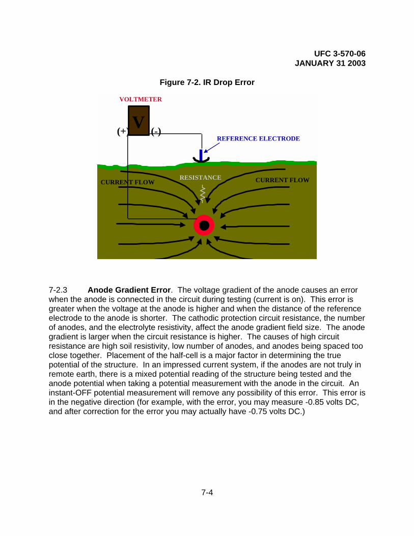
UFC 3-570-06 JANUARY 31 2003
7-4
Figure 7-2. IR Drop Error
V (-)(+)REFERENCE ELECTRODE
VOLTMETER
CURRENT FLOWCURRENT FLOWRESISTANCE
7-2.3 Anode Gradient Error. The voltage gradient of the anode causes an error when the anode is connected in the circuit during testing (current is on). This error is greater when the voltage at the anode is higher and when the distance of the reference electrode to the anode is shorter. The cathodic protection circuit resistance, the number of anodes, and the electrolyte resistivity, affect the anode gradient field size. The anode gradient is larger when the circuit resistance is higher. The causes of high circuit resistance are high soil resistivity, low number of anodes, and anodes being spaced too close together. Placement of the half-cell is a major factor in determining the true potential of the structure. In an impressed current system, if the anodes are not truly in remote earth, there is a mixed potential reading of the structure being tested and the anode potential when taking a potential measurement with the anode in the circuit. An instant-OFF potential measurement will remove any possibility of this error. This error is in the negative direction (for example, with the error, you may measure -0.85 volts DC, and after correction for the error you may actually have -0.75 volts DC.)

UFC 3-570-06 JANUARY 31 2003
7-5
Figure 7-3. Anode Gradient Error
7-2.4 Contact Resistance Error. Poor contact of the reference electrode to the electrolyte results in error. The contact resistance of the half-cell to earth is problematic under rocky or dry conditions. Apply water on dry ground and/or use a very high resistance voltmeter. Cathodic protection voltmeters have selectable input resistance from 1 million to 200 million ohms. Normally, 10 million ohms is the selected scale; while taking a potential measurement, switch the input resistance to the next higher selection. If the reading does not change, the contact resistance is insignificant. If the reading does change, select the next higher input resistance, and continue until the reading does not change. If the highest selection still changes the reading, add water and retest. This error is in the positive direction (for example, with the error you may measure -0.85 volts DC, and after correction for the error you may actually have -0.95 volts DC.) The input resistance of the meter used must be much greater than the contact resistance to ensure accuracy of the measurement.
V(-)(+)
REFERENCE ELECTRODE
VOLTMETER
(-)(+)R
RECTIFIER

UFC 3-570-06 JANUARY 31 2003
7-6
Figure 7-4. Contact Resistance Error
V(-)(+)
REFERENCE ELECTRODE
VOLTMETER
HIGH EXTERNAL RESISTANCE
LOW INTERNAL RESISTANCE
7-2.5 Mixed Potential Error. Error results when a potential measurement being taken on the structure is mixed with the potential of other structures also connected to the circuit being tested. This error can be significant when the coating on the structure being tested is very good and there are other structures in the area not isolated from the cathodic protection system. This error is present when the system being tested is not isolated, and is greater when the condition of the coating is better, the distance to the nearest holiday is greater, the distance of the half cell to the other structure is shorter, when the coating of the other structure is worse (or bare), and when the native potential of the other metal is less negative (more cathodic, such as copper). This error is usually in the positive direction (for example, you may measure -0.85 volts DC, and after correction for the error you may actually have -0.95 volts DC). This error can be in the negative direction if caused by contact with a more negative (more anodic) metal, such as aluminum, zinc (galvanized steel), magnesium, or some stainless steels in the passive state.
Another source of a more positive mixed potential could be a small anodic area on the structure being tested, with larger cathodic areas on the same structure influencing the potential measurement. This error is greater when the size of the more positive area is smaller, the distance of the reference electrode to the structure is greater, and when the size of the more negative area is greater.

UFC 3-570-06 JANUARY 31 2003
7-7
Figure 7-5. Mixed Potential Error
7-3 PRACTICAL MEASUREMENT OF CATHODIC PROTECTION POTENTIALS
7-3.1 Test Criteria Selection. The method used for potential testing varies widely for different types of structures and for the different criteria used for evaluation of the potentials taken. Sometimes different criteria may be used for different areas on the same structure. The criteria selected depend mostly on the type of the structure, isolation/non-isolation of the structure, structure coating type and efficiency, the type of cathodic protection system, the soil resistivity, the amount of current supplied by the CP system, and the instrumentation available for testing.
7-3.1.1 Sacrificial Cathodic Protection System. Generally, the criterion for sacrificial CP systems is -0.85 ON. IR error must be compensated for, usually by placing the reference electrode as near to the structure as possible (directly over the pipeline or tank) and as remote as possible from any sacrificial anode. This, combined with knowledge of the structure coating, soil resistivity, the size and spacing of the anodes and the anode current, is usually enough to determine the adequacy of the CP applied to the structure. If in doubt, or when potential readings are questionable, excavate to allow placement of a temporary reference electrode or permanent reference electrode as close as practical to the structure to further minimize any possible IR error. Sacrificial systems are normally used in low soil resistivities (low IR error), on well coated structures with a low current requirement (low IR error), and because of the very small driving voltage (under one volt), have a very small amount of current flow (low IR error). If the dielectric strength of the structure coating is not good, the soil resistivity is
V(-)(+)
REFERENCE ELECTRODE
VOLTMETER
METALLIC CONTACT
FOREIGN STRUCTURE

UFC 3-570-06 JANUARY 31 2003
7-8
relatively high, or the location or spacing of the anodes makes it impossible to measure the structure potential remote from the anodes, other criteria should be used or excavations made to properly place the reference electrode to obtain a valid potential measurement. For very small and well-coated structures (such as valves, elbows, and tie downs), use the 100 mV polarization criterion. For all sacrificial systems, if the sacrificial system is designed to allow interrupting the current from all anodes simultaneously, the -100 mV polarization criterion could be used. The -0.85 instant-OFF criterion is usually not attainable in most soil conditions with sacrificial anodes, unless the native potential of the structure is very high and/or the soil resistivity is very low. The -0.85V instant-OFF criterion should not be used for sacrificial CP systems except in rare cases; use the 100 mV shift criterion or the -0.85 ON criterion (considering IR).
7-3.1.2 Impressed Current Cathodic Protection System. The first consideration for determining the criteria to use with impressed current CP systems is the type of anode bed used.
• For distributed anode impressed current systems, the -0.85 instant-OFF or the 100 mV polarization criterion should be used; the -0.85 ON criterion should not be used. For structures with a high dielectric strength coating, the -0.85 instant-OFF criterion may be the easiest to use, although the 100 mV polarization criterion can be used. For structures which are bare, poorly coated, or have a deteriorated coating, the 100 mV polarization criterion should be used.
• For remote anode impressed current systems, all criteria, or a mixture of criteria may be used. If the anodes are truly remote from the test point, the electrolyte resistivity is low, the dielectric strength of the coating is high, and the circuit resistance of the CP system is low, the -0.85 ON criterion (considering IR error) is sufficient. Accounting for voltage drops other than those across the structure-to-electrolyte boundary is usually accomplished by placing the reference electrode as near to the structure as possible (directly over the pipeline or tank). This, combined with knowledge of the dielectric strength or the structure coating, size of the structure, the electrolyte resistivity, the distance and voltage at the anodes, the rectifier output voltage, and the rectifier output current, is usually enough to determine the adequacy of the CP applied to the structure. If in doubt, or when potential readings are questionable, test the location using another criterion, or excavate to locate a temporary reference electrode (or install a permanent reference electrode) as close as practical to the structure to further minimize any possible IR error. For structures with a high dielectric strength coating, regardless of the electrolyte resistivity, distance from the anodes, or the CP system circuit resistance, the -0.85 instant-OFF criterion may be the easiest to use,

UFC 3-570-06 JANUARY 31 2003
7-9
although the 100 mV polarization criterion can be used. For structures which are bare, poorly coated, or have a deteriorated coating, the 100 mV polarization criterion should be used.
7-3.2 Test Methods for the -0.85 ON Criterion. A single electrode potential survey is conducted using any high impedance or high input resistant voltmeter (10 megaohms or higher). The voltmeter positive is connected to the structure under test and the voltmeter negative is connected to the reference electrode to display the proper polarity (for analog meters which only read in the positive direction, the leads must be connected backwards to get an upscale deflection, and the negative value must be inserted when recording the measurement). The -0.85 volts DC is measured to a copper/copper sulfate reference electrode (half cell). Other types of reference electrodes must be corrected to the copper/copper sulfate reference to use the -0.85 volt criterion.
Figure 7-6. Single Electrode Potential Survey
V oltm eter
-+
1 2R eferenceElectrode
Test Station
V oltm eter
-+
In terval
Wire R eel
Insulated Wire
7-3.2.1 Since these potential readings are taken with the cathodic protection current on, there are errors in the measurement which must be considered to obtain a valid conclusion that adequate cathodic protection exists on the protected structure. Chapter 6 of this handbook and NACE International Recommended Practice (RP) 0169-92, Section 6.2.2 for steel and cast iron piping, states that voltage drops other than those across the structure-to-electrolyte boundary must be considered for valid interpretation

UFC 3-570-06 JANUARY 31 2003
7-10
of this voltage measurement. Consideration is understood to mean the application of sound engineering practice in determining the significance of voltage drops by methods such as:
• Measuring or calculating the voltage drop(s).
• Reviewing the historical performance of the cathodic protection system.
• Evaluating the physical and electrical characteristics of the pipe and its environment.
• Determining whether or not there is physical evidence of corrosion.
All the errors listed in paragraph 7-2 must be evaluated. Interruption of the CP current does not fall under this criterion, since that would pertain to the -0.85 instant-OFF or the 100 mV polarization criterion. Measuring or calculating the voltage drop(s) includes measuring all the factors that affect the magnitude of the voltage errors present in the ON reading. These measurements include the anode output, rectifier current output, structure coating efficiency, location of the reference cell in relation to the anodes and the structure, electrolyte resistivity, comparison to previous potentials (native, ON, and/or instant OFF) and other factors which may contribute to the corrosion rate (presence of stray current, interference, bi-metallic connections, pH, temperature, homogeneity of the soil, amount of oxygen, presence of bacteria, and presence of other ions or contaminants which may affect the corrosion rate). Implementation of this criterion is only possible when these factors can be quantitatively verified by measurement these factors, or historical evidence that these factors have been considered.
7-3.2.2 Factors that decrease magnitude of the voltage drop errors or otherwise slow or stop the corrosion rate include:
• High dielectric strength coating. A 99 percent to 99.7 percent effective coating drastically lowers the amount of current to obtain adequate cathodic protection; consequently IR error is also drastically lowered.
• Low electrolyte resistivity. As resistivity is lowered, the IR drop error is lowered. Also for impressed current systems, the circuit resistance is lower, resulting in a lower voltage at the anode (to obtain the same current), lowering any anode gradient errors.
• High pH (7 to 13). A high pH in the electrolyte near the protected structure indicates cathodic protection is present, but amphoteric materials could be damaged by the high alkalinity created by the cathodic protection.

UFC 3-570-06 JANUARY 31 2003
7-11
• Low temperatures, which decrease the corrosion rate.
• Current density.
• Lack of bimetallic connections. If present they would raise the corrosion rate.
• Lack of interference corrosion. Interference raises the potential in the pickup area (lowers corrosion) and lowers the potential in the discharge area (increases the corrosion rate).
7-3.3 Test Methods for the -0.85 Instant-OFF Criterion. For this criterion, measurements of potential must be taken when there is no cathodic protection current flowing. The measurement of the instant-OFF or the potential when the cathodic protection is not flowing is required as the means of removing errors from the measurement. For various methods used to measure the instant-OFF potential, see paragraph 7-3.5. If the potential measurement meets or exceeds -0.85 volts DC (in comparison to a copper/copper sulfate reference electrode) using these methods, this criterion has been met. Other reference electrodes must be corrected to the factor for a copper/copper sulfate reference to be valid under this criterion.
7-3.4 Test Methods for the 100 mV Polarization Criterion. The test method for this criterion is exactly like the method for the negative 0.85 instant-OFF criterion, with the additional requirement of either comparing the measurements to a native survey (potentials taken before the cathodic protection current was applied), or allowing for the measurement of the polarization decay. It is recommended that the native potentials be used to compare the instant-OFF readings for the 100 mV polarization criterion. After cathodic protection has been applied, the structure is polarized, and even after current interruption, considerable time may be required before the potential returns to the native potential value. Measuring polarization decay guarantees the proper shift, but may require considerably more current to polarize the structure to a level where the 100 mV depolarization would occur in a relatively short time.
7-3.5 Instant-OFF Test Methods. The test method used for an instant-OFF potential measurement is determined by the type of equipment used and the type of current interrupter used. The test method must include interruption of the protective current or measurement of the potential when there is no current flowing, to guarantee the removal of all IR drop and anode gradient errors. There are four different equipment technologies that are used and several ways to accomplish the current interruption (sometimes depending on the type of equipment being used). Types of equipment include:
7-3.5.1 A normal high input impedance digital voltmeter may be used in combination with conventional current interrupters, manually synchronizable, or advanced

UFC 3-570-06 JANUARY 31 2003
7-12
synchronizable interrupters (not pulse generators, unless used as a conventional interrupter).
7-3.5.2 A data logger which records potential measurements very quickly (from four to several thousand readings per second) may be used in combination with conventional current interrupters, manually synchronizable, or advanced synchronizable interrupters (not pulse generators, unless used as a conventional interrupter), then analyzing the data (sometimes using computer software) to determine the instant-OFF potential reading.
7-3.5.3 A waveform analyzer may be used together with a pulse generator to calculate the OFF potential.
7-3.5.4 A high speed data logger and oscilloscope (or similar very high speed recording device) may be used to analyze the unfiltered signal on the structure to obtain the potential of the structure when the DC output waveform is at zero current output. This technology may only be applicable with potential measurements that are affected by only one single-phase rectifier, with all filters and chokes disconnected from the rectifier output and may not remove all anode gradient errors.
7-3.6 Types of Interrupters. The type of interrupter used depends on the number of rectifiers or DC current sources and the type of equipment used to perform the instant-OFF measurements. Manual interruption of a cathodic protection rectifier using an AC power switch, rectifier circuit breaker, or other means is generally not recommended. The time to manually open and close contacts, coupled with interruption of the AC side of the circuit does not provide accurate or repeatable measurements under many conditions within the first second of interruption, resulting in significant inaccuracies in the measurement obtained. Manually operated relay contacts are sometimes used, and may produce repeatable results if they have a quick open and closed mechanism and are installed in the DC output of a rectifier. Using radios to signal operators to open and close contacts, breakers or switches could also produce erroneous readings due to RF signals from the radio which may induce voltages in the meter being used to measure or record the measurement, especially with analog meters or unfiltered digital meters.
7-3.6.1 Conventional Interrupter. The conventional current interrupter provides for timed interruption of a rectifier DC output current. This is normally accomplished by opening the circuit either between the anodes and the rectifier, or the structure and the rectifier. Units normally provide independent control of open and closed time intervals. Variations in the accuracy of the interruption timing, current ratings of the relay contacts, and the selection increments of the on and off cycles vary between units. These units are normally installed temporarily in the rectifier output circuit during testing, but sometimes are optionally installed in the rectifier cabinet. Quartz crystal controlled units are usually accurate to within one second a day. These units are typically powered by

UFC 3-570-06 JANUARY 31 2003
7-13
batteries installed internally, or with an external DC power source through a panel plug.
7-3.6.2 Manually Synchronizable Interrupter. This unit is similar to a high quality conventional interrupter (may be accurate to within one tenth of a second in 24 hours) with the additional feature of synchronizing the interruption cycle with other like units. This is normally accomplished by using a supplied cable to temporarily connect two units together, to start second, third, fourth, etc., units for synchronization of the interruption cycles of all units. These units make it possible to interrupt several rectifiers simultaneously to use various instruments to measure an instant-OFF potential reading. They are usually portable, but could possibly be installed equipment, with a portable unit used to synchronize the rectifier-installed units.
7-3.6.3 Advanced Synchronizable Interrupter. These units are similar to a manually synchronizable interrupter with the means of synchronization controlled by some communication technology (versus manually by cable connection) such as radio, computer connection, modem, or satellite transmissions. They are usually permanently installed, but portable units are also available.
7-3.6.4 Pulse Generator. The pulse generator can normally be used as a conventional current interrupter or as a standard pulse generator. They may be permanently or temporarily installed in the rectifier cabinet. They do not require synchronization when used together with the proper waveform analyzing equipment. If used for a conventional current interrupter, they are not synchronizable, but usually provide for user-selectable interrupt cycles. The standard pulse generator is connected in series in the DC output (either positive or negative) of the rectifier(s) and produces a precisely timed, zero-current pulse that does not drift. AC supply voltage is used to power the pulse generator. Selectable input AC power units must be set for the correct AC supply voltage being used. Ensure the pulse generator is set to the proper voltage before applying AC power, or the pulse generator will be damaged.
7-3.7 Specific Methods for Various Instant-OFF Potential Measurement Techniques
7-3.7.1 Using Normal Digital Voltmeter with Current Interrupter(s). The digital voltmeter may be used together with a current interrupter to measure an instant-OFF potential. For locations that are affected by more than one rectifier or DC current source, synchronized interruption must be accomplished. For locations that are affected by more than three to six rectifiers or DC current sources (according to their contribution or availability of synchronizable interrupters), subsequent systems can be turned off to preclude their contribution to the instant-OFF reading.

UFC 3-570-06 JANUARY 31 2003
7-14
Figure 7-7. Typical Displayed Readings Using Digital Voltmeter
• Limitations of a meter using a needle to display the measurement (D’Arsonval movement) preclude their use for this application. The needle swing is a relatively slow movement which may be slower than the initial depolarization which occurs after interruption; by the time the needle swing catches up with the actual measured potential, significant depolarization may have already occurred. If used, this technique would yield a measurement value that is less than the actual instant-OFF, which can be measured using other methods.
• Typical digital voltmeters take hundreds or thousands of readings a second, but normally update the display only after a change in the reading or about every ¼ of a second under constantly changing conditions. The actual instant-OFF measurement must be determined by viewing the digital display and manually recording the measurement. Since the display is updated only after a change, and is only updated about every ¼ second under changing conditions, the display must be interpreted. Normally, the display is constant (not changing) while the current is on. When the current is interrupted, the meter must recognize the change, average the measurement and update the display. This first blink contains an average of all the ON, all the OFF, and any spiking (either positive or negative) which has occurred since the last display update or about ¼ of a second. This first blink is not the instant-OFF: It contains part of the ON
1.0251.0251.025
10.8650.8550.845
1.021.0221.0251.0251.0251.0251.0251.0251.025
g g
0
0.2
0.4
0.6
0.8
1
1.2
1 5 9 13 17 21 25 29 33 37 41 45 49
Instant-OFF
Interrupter Set at 1 Second Off and 4 Seconds On
Negative Volts
Number of Readings at 1/4 Second Intervals

UFC 3-570-06 JANUARY 31 2003
7-15
and should be disregarded. The second blink is the instant-OFF measurement, which should be recorded. Since this number is only displayed for about ¼ of a second, watching the display through several interruption cycles may be required to assure the correct value is recorded. The value recorded using this technique will have from about 1/8 of a second to just under ½ of a second of depolarization.
• Some digital meters have a memory function that will remember the minimum and maximum (ON and instant-OFF) readings and the meter can toggle between the two readings. Using this type of digital meter with the interrupter(s) on a short off cycle (usually 1 second), the meter can be reset, then the ON and instant-OFF displayed and recorded. The value recorded using this technique will have from about ½ to just less than 1 second of depolarization (with a 1 second OFF cycle). Some interrupters are available which have the capability of a ½ second OFF cycle, which could be used to obtain approximately the same accuracy as the previous method (1/8 of a second to just under ½ of a second of depolarization).
• There are occasions where a significant depolarization may occur in the time required for these methods to obtain an instant-OFF reading. The speed of depolarization depends on the type of coating, the condition of the coating, the dielectric strength of the coating, the current density, and the type of electrolyte.
Figure 7-8. Readings Recorded by Digital Voltmeter with Minimum/Maximum Function (Reference Cell to Meter Negative, Structure to Meter Positive)
1.0251.0251.0251.025
10.8650.8550.8451.02
1.0221.0251.0251.0251.0251.0251.0251.0251 025
0
0.2
0.4
0.6
0.8
1
1.2
1 5 9 13 17 21 25 29 33 37 41 45 49
Maximum Recorded (most positive)
Number of Readings at 1/4 Second Intervals
Interupter Set at 1 Second Off and 4 Seconds On
MinimumNegativeVolts
7-3.7.2 Using a Data Logger with Current Interrupters. As with digital meters,

UFC 3-570-06 JANUARY 31 2003
7-16
current interruption is required. The data logger records from four to several thousand readings per second. The measurements taken are not an average over time as with the digital meters. The location being tested is measured through at least one OFF cycle and the instant-OFF reading is extracted manually from the data, or extracted via a computer program that is designed for that purpose. Any positive or negative spiking that may occur when the current is interrupted or when it goes back on should be disregarded and is not considered a valid instant-OFF reading. Fast data loggers record more data resulting in a higher accuracy, but often require more time to extrapolate the correct reading. Very fast data loggers may require software analysis of the data to get the instant-OFF readings in a timely manner. Manually verify a representative sampling of the data to ensure the software is effectively extrapolating the correct reading. The value recorded using this technique will have from about zero (0.0003 seconds at 3000 per second) to under ¼ of a second (at four per second) of depolarization, according to the sampling speed of the data logger. It is possible at four readings per second to record a positive or negative spike as one of the readings (depending on synchronization timing and the sampling timing of the data logger). In that case, the next reading would have a full ¼ second of depolarization.
Figure 7-9. Examples of Voltage Spiking on Instant-OFF Readings
1.0251.0251.0251.45
0.8720.8670.8640.8610.8580.8550.8530.8510.849
0
0.2
0.4
0.6
0.8
1
1.2
1.4
1.6
1 6 11 16 21 26 31 36 41 46 51 56 61 66 71 76 81 86 91 96 101
106
111
7-3.7.3 Using a Waveform Analyzer with a Pulse Generator. The waveform analyzer is a microprocessor-based hand-held voltmeter that uses a complex computer algorithm to measure the ON and instant-OFF potentials. To accurately calculate the OFF potential, a pulse generator must be installed in all rectifiers or DC current sources that affect the location where the measurement is being made. The pulse generator interrupts the output of the rectifier on a precise timing cycle. This interruption generates the precisely timed zero current pulse which is required by the waveform
Milliseconds
Negative Voltage Negative Spiking
Positive Spiking(Can affect Instant OFF Readings)
(Can affect ON Readings)
ON ON
ON
ON
OFF
OFF OFF OFF

UFC 3-570-06 JANUARY 31 2003
7-17
analyzer to accurately calculate the OFF potential. Pulse generators do not require any synchronization. The waveform analyzer captures a digital picture of the potential waveform by recording thousands of voltage readings on the waveform. Digital signal processing techniques are then used to filter out any induced AC or 60-cycle noise in the waveform and the ON potential reading is calculated. The error from the six pulse generators having the greatest influence on the reading is determined by analyzing the zero current pulses from all pulse generators affecting the waveform, and the OFF potential reading is calculated by subtracting the error from the ON reading. If the location under test is suspected to have more than six rectifiers or DC current sources significantly affecting the potential, separate testing should be conducted to verify or eliminate that possibility. If there are more than six sources of current affecting the potential at a particular location, determine the six sources with the greatest influence and turn the rest off so that their effect is not considered as part of the off potential. The value recorded using this technique will have very little or no depolarization in the measurement.
7-3.7.4 Using a High Speed Data Logger and a Filtered Oscilloscope. The oscilloscope is used to analyze the rectifier output waveform, and the high-speed data logger is used to obtain a digital picture of the potential signal on the structure. This technology simultaneously measures the rectifier output waveform and the potential waveform, and by comparison extrapolates the potential measurement when the rectifier waveform is at zero current. This technology may only be applicable with potential measurements that are affected by only one single-phase rectifier, with all filters and chokes disconnected from the rectifier output. Since the data logger is connected to the structure with a closed circuit to the anodes through the rectifier, the potential of the anodes could still affect the potential measurement if readings are taken in the vicinity of the anodes. On a well-coated structure, the distance required to remove the possibility of a mixed potential (anode and structure) would be greater. This technology will not work with a three-phase rectifier system or where more than one rectifier is protecting the structure.
7-4 STRUCTURE-TO-SOIL POTENTIAL LIMITS
7-4.1 Excessive Cathodic Protection Current. Excessive cathodic protection current produces hydrogen gas evolution at the surface of the cathode. If the gas is produced faster than it can permeate the coating, bubbling of the coating will occur. The amount of coating damage is dependent on the amount of gas generated and the type of coating. This condition is normally called “blowing off” the coating. When this occurs, more of the structure is exposed to the electrolyte and the circuit resistance between the anodes and the cathode becomes lower. This causes more current to be impressed to this location, and usually, more gas evolution. This phenomenon results in more coating damage and is very detrimental to current distribution, since more current goes to that location, and less current goes to other, more remote, locations.

UFC 3-570-06 JANUARY 31 2003
7-18
7-4.2 Water Storage Tanks. The coatings used in water storage tanks are the most prone to this damage. This type of coating disbonds very easily as compared to coatings used on underground structures. It is not uncommon for elevated or ground level water storage tanks to have the coatings bubbled or blown off from excessive cathodic protection. It is essential on these tanks to maintain the level of current at a safe level. The accuracy of permanent reference electrodes used with automatic systems should be of concern when performing the CP System Check. The ON potentials of coated water storage tanks have many errors in the measurement (paragraph 7-2.3). ON potential measurements over -1.10 volts DC to a copper/copper sulfate reference electrode should be suspected of coating damage and instant-OFF potentials taken. Coating damage should be expected when the potential measurement is over -1.50 volts DC to a copper/copper sulfate reference electrode and instant-OFF potentials must be taken. The instant-OFF potentials should not exceed -1.00 volt DC and must never exceed -1.10 volts DC to a copper/copper sulfate reference electrode.
7-4.3 Underground Structures. Coatings for underground structures are generally resistant to this damage. The ON potentials of underground structures also have many errors in the measurement (paragraph 7-2.3). ON potential measurements to a copper/copper sulfate reference electrode should be suspected of coating damage if over the potentials listed in Table 23 “SUSPECTED” column, and instant-OFF potentials should be taken. Coating damage should be expected when the potential measurement is over the potential listed in Table 23, “EXPECTED” column, and instant-OFF potentials must be taken. This figure assumes an IR drop error and is given for information only. The only true way to measure this possible damage is with an error-free measurement (paragraph 7-3). Instant-OFF measurements should be used whenever possible. Instant-OFF measurements that are over approximately -1.22 volts DC are not theoretically possible. If instant-OFF readings are significantly over -1.22 volts DC, other DC current sources are present. Synchronous interruption of all current sources must be accomplished.
7-4.3.1 For fusion-bonded coatings, the instant-OFF potentials should not exceed -1.07 volts DC and must never exceed -1.12 volts DC to a copper/copper sulfate reference electrode.
7-4.3.2 For coal tar coatings, the instant-OFF potentials should not exceed -1.12 volts DC and must never exceed -1.20 volts DC to a copper/copper sulfate reference electrode.
7-4.3.3 For plastic tape coatings, the instant-OFF potentials should not exceed -1.02 volts DC and must never exceed -1.07 volts DC to a copper/copper sulfate reference electrode.
7-4.3.4 For other coatings, refer to specifications for cathodic disbondment properties compared to above coatings.
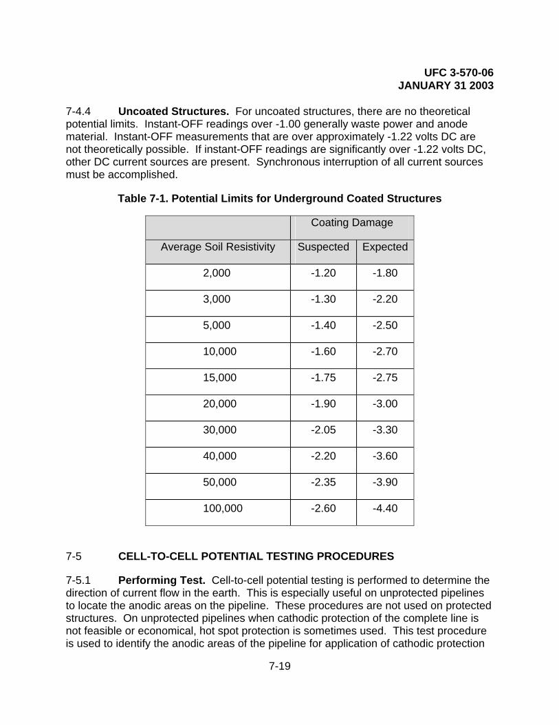
UFC 3-570-06 JANUARY 31 2003
7-19
7-4.4 Uncoated Structures. For uncoated structures, there are no theoretical potential limits. Instant-OFF readings over -1.00 generally waste power and anode material. Instant-OFF measurements that are over approximately -1.22 volts DC are not theoretically possible. If instant-OFF readings are significantly over -1.22 volts DC, other DC current sources are present. Synchronous interruption of all current sources must be accomplished.
Table 7-1. Potential Limits for Underground Coated Structures
Coating Damage
Average Soil Resistivity Suspected Expected
2,000 -1.20 -1.80
3,000 -1.30 -2.20
5,000 -1.40 -2.50
10,000 -1.60 -2.70
15,000 -1.75 -2.75
20,000 -1.90 -3.00
30,000 -2.05 -3.30
40,000 -2.20 -3.60
50,000 -2.35 -3.90
100,000 -2.60 -4.40
7-5 CELL-TO-CELL POTENTIAL TESTING PROCEDURES
7-5.1 Performing Test. Cell-to-cell potential testing is performed to determine the direction of current flow in the earth. This is especially useful on unprotected pipelines to locate the anodic areas on the pipeline. These procedures are not used on protected structures. On unprotected pipelines when cathodic protection of the complete line is not feasible or economical, hot spot protection is sometimes used. This test procedure is used to identify the anodic areas of the pipeline for application of cathodic protection

UFC 3-570-06 JANUARY 31 2003
7-20
to those locations. The polarity of the voltage difference between the two reference cells indicates the direction of current flow.
7-5.2 Accuracy. The accuracy of the reference electrodes (half cells) used to take cell-to-cell measurements must be determined. Perfect matching of the two reference cells is not essential, but the error must be accounted for in all measurements taken. The accuracy of the two half-cells is determined by measuring the difference in potential between the two half cells being used for the test. Use a suitable voltmeter on the millivolt scale and place the two cells cone-to-cone, and measure the potential difference. The potential difference should not be in excess of 5 mV. If no “reference” reference electrode is available, follow paragraph 7-2.1.1 on a new or used half-cell to get a reliable reference electrode, then test the potential difference (in mV) to other half cells. When a reference electrode is first initiated, time must be allowed for the cone to become saturated. This process takes up to two hours, but can be speeded up by placing the half-cell, cone end down, in a container of copper sulfate solution. See paragraph 7-2.1 for the procedures for checking the reference electrodes.
Figure 7-10. Positive Reading for Cell-To-Cell Survey
V oltm eter
-+1 2
ReferenceElectrodeElectrode
R eference
Current Flow in the Earth
Direction of Anodic A rea on Pipeline

UFC 3-570-06 JANUARY 31 2003
7-21
Figure 7-11. Negative Reading for Cell-To-Cell Survey
7-6 RECTIFIER EFFICIENCY TESTING PROCEDURES
7-6.1 Determining Efficiency. The efficiency of a rectifier is determined by measuring the output voltage (paragraph 5-2.1), output current (paragraph 5-2.2), calculating the input in watts, and using the following formula:
Output Current X Output Voltage Rectifier Efficiency = Input Watts
**Input Watts = Revolutions per hour of the kWh meter disc X factor shown on the face of the kWh meter.
7-6.2 Alternate Procedure. An alternate procedure to obtain the input watts is simply measuring the AC input voltage (paragraph 5-2.1) and the AC input current (by using an accurate clamp-on ammeter or by disconnecting and measuring AC amps with appropriate procedures similar to 5-2.1, measuring AC voltage). This method neglects the power factor and will not be truly accurate, but will give a reasonable approximation. If this method is used, subsequent efficiency testing should be done in the same manner to obtain comparable results.
Output Current X Output Voltage Rectifier Efficiency = Input Current X Input Voltage
V oltmeter
-+1 2
R eferen ceElectrode Electrode
R eference
C urrent Flow in the Earth
D irection of A nod ic A rea on Pip eline

UFC 3-570-06 JANUARY 31 2003
7-22
Figure 7-12. Rectifier Efficiency
RECTIFIER EFFICIENCIES
020406080
100120140160
0 10 20 30 40 50 60 70 80 90
PERCENT OF RATED VOLTAGE OR CURRENT
PER
CEN
T EF
FIC
IEN
CY
AT FULL RATED CURRENT
AT FULL RATED VOLTAGE
100
EXAMPLE: 10% Voltage at Full Rated Current = 40% Efficiency
7-6.3 Expected Efficiency. The expected efficiency of a rectifier depends on the type of AC power (single or three-phase), Type of rectifying elements (selenium or silicon), type of rectifier (bridge or center tap), and the percent of load of the unit. The selenium bridge rectifier is the most common unit. The selenium inherently is less efficient due to the voltage drop of the rectifier elements (and resultant heat). Selenium ages with time and becomes less efficient as time passes.
7-7 DIELECTRIC TESTING PROCEDURES. Shorted dielectrics adversely affect the operation of cathodic protection systems. If a cathodic protection system is designed to protect an isolated structure, shorted dielectrics will normally result in loss of adequate protection to that structure. Shorts may also result in poor current distribution or shielding which will result in the loss of adequate protection to areas of the structure. Testing an installed dielectric presents several problems. Since typical installations normally include many dielectrics, all of which are in a parallel circuit, failure of one dielectric can effectively short the entire system. There are indications of the shorted condition of one dielectric at many, or all, other dielectrics installed. Usually, the further the distance is between the dielectric being tested and the dielectric that is shorted, the easier it is to test that dielectric. Most methods of testing a dielectric give a reliable indication of only one condition of the dielectric (either shorted or not shorted condition) and further testing may be required for the other condition. Only one method gives a totally reliable indication of an installed dielectric. The radio frequency tester (insulated flange tester), because of its wavelength and the strength of the signal, gives a true indication of the condition of that specific dielectric. This method will not read through other parallel paths, even when these paths are in the immediate vicinity. In fact, this method can pinpoint the fault to a particular flange bolt or the flange gasket. Therefore, this method should be used for testing when any other method is not

UFC 3-570-06 JANUARY 31 2003
7-23
conclusive. The preferred method to determine if a dielectric may be shorted is by potential testing. This method will normally provide an immediate indication if the dielectric is not shorted, and at the same time provide valuable potential data. If this method indicates the dielectric may be shorted, other methods of verification are be required. The radio frequency tester (insulated flange tester) should be used when a shorted condition is indicated by potential measurements. Alternate methods of verification may be used to test installed dielectrics. These methods include the pipe locator method (paragraph 7-7.3), which can determine that an installed dielectric is bad, but does not give conclusive evidence if the test indicates that the dielectric is good; and the power supply method (paragraph 7-7.4), which can determine that an installed dielectric is good, but does not give conclusive evidence if the test indicates that an installed dielectric is bad.
CAUTION: Do not use an ohmmeter to measure resistance of an installed dielectric. If the dielectric is good, current will flow through the meter and damage could result. If that current does not damage the meter, the measurement would not indicate a resistance value. The voltage would be interpreted by the meter as coming from the internal battery instead of the external electrical circuit being measured.
7-7.1 Testing for a Shorted Dielectric. Take a potential measurement of both sides of the installed dielectric by changing only the structure connection, without moving the copper/copper sulfate reference electrode.
Figure 7-13. Testing for a Shorted Dielectric
7-7.1.1 If the two potential measurements are significantly different (over 10 mV), the
Voltmeter
-+1
2ReferenceElectrode
Test Station orMetallic Contact
House Side of Dielectric
Street Side of Dielectric
to Pipeline

UFC 3-570-06 JANUARY 31 2003
7-24
dielectric is good. The street side of the dielectric, under normal conditions (with cathodic protection) should be at a potential more negative than -0.85 volts DC and the house side of the dielectric should be between approximately -0.15 volts DC and -0.45 volts DC (a difference of between 400 and 700 mV). If the dielectric is good and the house side of the dielectric has a potential more negative than expected, another shorted dielectric in the area should be suspected, and further investigation is required (for example, if the house side potential reading is over -0.65, with a street side potential the same or more negative).
7-7.1.2 If the two potential measurements are not significantly different (under 10 mV), the dielectric may be shorted and additional testing is required. The preferred method is to use a radio frequency tester (insulated flange tester) to test that specific dielectric (paragraph 7-7.2). Other possible methods that may or may not be conclusive include using the pipe locator method (paragraph 7-7.3) or the power supply method (paragraph 7-7.4).

UFC 3-570-06 JANUARY 31 2003
7-25
7-7.2 Using a Radio Frequency Tester. This method is the most accurate and conclusive method of testing a dielectric. Turn the insulated flange tester test switch to “zero,” turn the control knob on, and zero the needle indicator. Turn the test switch to “test,” and without turning the control knob, test the dielectric.
Figure 7-14. Testing an Installed Dielectric with the Insulated Flange Tester
7-7.3 Using a Pipe Locator. Two different types of pipe locators may indicate that a dielectric is bad. One uses a short wave length signal (paragraph 7-7.3.2) and one uses the signal from an impressed current system (60-cycle “noise”—this method can only be used on impressed current systems with a single phase rectifier)(paragraph 7-7.3.1). These methods give a rapid indication if the dielectric is shorted, but may not be conclusive.
InsulatedFlangeTester
InsulatedFlangeTester

UFC 3-570-06 JANUARY 31 2003
7-26
Figure 7-15. Testing for a Shorted Dielectric Using a Pipe Locator
Test Station or
Signal
Signal
M etallic C ontact
SignalGenerator
(if requ ired)
Pipe Locator
7-7.3.1 The Pipe Horn, Model FDAC200, detects the signal from a single-phase rectifier. With the impressed current system on, this locator can be used to follow the underground pipeline. If a dielectric is shorted, and the current is sufficient, the locator will follow the signal across the dielectric. Consequently, if the signal is followed through the dielectric, that dielectric is bad. If no signal can be followed, verify with the insulated flange tester (paragraph 7-7.2).
7-7.3.2 A short wave length pipe locator, using a direct connection, detects the signal from a signal generator. To obtain a strong signal, ensure that a good metallic connection is made, a good battery is installed in the signal generator, and most importantly, that the signal generator has a good, low resistant ground. This locator can then be used to follow the underground pipeline. If a dielectric is shorted, and the signal is sufficient, the locator will follow the signal across the dielectric. Consequently, if the signal is followed through the dielectric, that dielectric is bad. If no signal can be followed, verify with the insulated flange tester (paragraph 7-7.2).

UFC 3-570-06 JANUARY 31 2003
7-27
Figure 7-16. Testing for a Shorted Dielectric with Power Supply
V oltm eter
-+1
2
R eferenceElectrod e
- +
Temporary
Su pp lyPow er
TemporaryA nodes
Over 50 Feet
7-7.4 Using a Temporary Local Cathodic Protection System. Install a temporary local cathodic protection system to increase the current to the street side of the dielectric (paragraph 7-10); or if possible, merely increase the current level of the existing system. Note that the temporary system should be installed where the current should distribute to the location being tested. Repeat the potential measurement of both structures. If the potential of the house side of the dielectric remains approximately the same or changes in a positive direction (less negative), when the potential of the street side of the dielectric changes in a negative direction, they are not shorted. If both potential measurements change more negative as current is increased, the two structures are shorted together.
7-8 CASING TESTS. Casings present a unique and sometimes very challenging problem to corrosion control. Although they are required in some cases, they present a serious problem to the application of cathodic protection to the carrier pipe. If not shorted, they may shield adequate protection; and if shorted, they totally shield the carrier pipeline and steal the cathodic protection, often for a large area of the pipeline. The preferred method of corrosion control is to isolate and seal the casing so there is no electrolyte in the space between the casing and the carrier pipe, or fill that area with a nonconductive sealant. Casings are normally bare, while carrier pipelines are normally very well coated. Casings normally have vent pipes at one or both ends and a test station for corrosion control testing. This test station usually has four wires, two to the

UFC 3-570-06 JANUARY 31 2003
7-28
casing and two to the carrier pipeline. If there is not a test station already installed, one should be installed prior to testing. At a minimum, there must be a metallic connection made to the carrier pipeline and a vent pipe that is connected metallically to the casing. If there is no vent pipe or carrier pipe test point in the vicinity of the casing, you must excavate to the carrier pipeline or the casing, as required, and test connections. Again, a test station should be installed.
Figure 7-17. Typical Casing Installation
TEST STA TIONV ENT PIPE
CASING
R OA D OR R AILW AY
CARRIER PIPELINE
CAUTION: Do not use an ohmmeter to measure resistance between the carrier pipeline and the casing. If the isolation is good, current will flow through the meter and damage could result. If that current does not damage the meter, the measurement would not indicate a resistance value. The voltage would be interpreted by the meter as coming from the internal battery instead of the external electrical circuit being measured.
7-8.1 Testing a Casing with Cathodic Protection on the Carrier Pipeline. Take a potential measurement of the carrier pipeline and the casing by changing only the structure connection without moving the copper/copper sulfate reference electrode.

UFC 3-570-06 JANUARY 31 2003
7-29
Figure 7-18 Testing for a Shorted Casing
V oltm eter
-+1
2 R eferenceElectrode
7-8.1.1 If the two potential measurements are significantly different (over 10 mV), the casing is not shorted to the pipeline. Under normal conditions, the carrier pipeline should be at a potential more negative than -0.85 volts DC, and the casing should be between approximately -0.35 and -0.65 volts DC (a difference of between 200 to 500 mV).
7-8.1.2 If the two potential measurements are not significantly different (under 10 mV), the casing may be shorted to the pipeline and additional testing is required. Install a temporary local cathodic protection system to increase the current to the carrier pipeline (paragraph 7-10); or, if possible, merely increase the current level of the existing system. Note that the temporary system must be installed on the opposite side of the railway or road crossing from the location of the potential testing. Repeat potential measurement of the carrier pipeline and the casing. If the potential of the casing remains approximately the same, or changes in a positive direction (less negative), when the potential of the carrier pipe changes in a negative direction, the insulation is good. If both the carrier pipeline and the casing potential measurements change more negative as current is increased, the carrier pipeline is shorted to the casing.

UFC 3-570-06 JANUARY 31 2003
7-30
Figure 7-19. Testing for a Shorted Casing with Power Supply
7-8.2 Testing a Casing Without Cathodic Protection on the Carrier Pipeline. Install a temporary local cathodic protection system to apply current to the carrier pipeline (paragraph 7-10). Always install the temporary anodes on the opposite side of the crossing from the side where the potential measurements are taken. Take a potential measurement of the carrier pipeline and the casing by changing only the structure connection without moving the copper/copper sulfate reference electrode.
7-8.2.1 If the two potential measurements are significantly different (over 10 mV), the casing is not shorted to the pipeline. With sufficient current applied to the carrier pipeline, it should have a potential of approximately -0.85 volts DC and the casing should be between approximately -0.35 and -0.65 volts DC.
7-8.2.2 If the two potential measurements are not significantly different (under 10 mV), the casing may be shorted to the pipeline and additional testing is required. Increase the amount of current applied to the carrier pipeline (by turning up power supply or adding additional temporary anodes), then repeat potential measurement of the carrier pipeline and the casing. If the potential of the casing remains approximately the same or changes in a positive direction (less negative) when the potential of the carrier pipe changes in a negative direction, the insulation is good. If both the carrier pipeline and the casing potential measurements change more negative as current is increased, the carrier pipeline is shorted to the casing.
7-9 TESTING FOR A SHORT BETWEEN TWO STRUCTURES. Shorts between two structures can adversely affect the operation of cathodic protection
-+
Temporary
Su pplyPow er
TemporaryA nodes
Over 50 Feet
V oltm eter
-+1
2 R eferenceElectrod e

UFC 3-570-06 JANUARY 31 2003
7-31
systems. If a protected structure is designed to protect an isolated structure, shorts to other structures will normally result in loss of adequate protection to that structure. Shorts may also result in the current distribution being adversely affected, and consequent loss of protection to areas of the structure. Determination of shorted or isolated conditions is also important in the design phase of cathodic protection installations. The preferred method for testing for a short between two structures is potential testing. This method will normally provide immediate indication if the two structures are not shorted, and at the same time provide valuable potential data. The methods of potential measurement will vary slightly if cathodic protection is supplied to neither structure, one structure, or both structures. A power supply may be required if one or both structures do not have CP installed. If only one structure has CP, refer to the procedures in paragraph 7-9.1. If both structures have CP, refer to the procedures in paragraph 7-9.2. If neither structure has CP, refer to the procedures in paragraph 7-9.3.
CAUTION: Do not use an ohmmeter to measure resistance between the two underground structures. If the structures are isolated, current will flow through the meter and damage could result. If that current does not damage the meter, the measurement would not indicate a resistance value. The voltage would be interpreted by the meter as coming from the internal battery instead of the external electrical circuit being measured.
7-9.1 Testing for a Short Between Two Structures with Cathodic Protection on One Structure. Take a potential measurement of both structures by changing only the structure connection without moving the copper/copper sulfate reference electrode.

UFC 3-570-06 JANUARY 31 2003
7-32
Figure 7-20. Testing For A Short Between Two Structures
7-9.1.1 If the two potential measurements are significantly different (over 10 mV), the two structures are not metallically shorted together. Under normal conditions, the structure with cathodic protection should be at a potential more negative than -0.85 volts DC and the steel structure without cathodic protection should be between approximately -0.35 volts DC and -0.65 volts DC (a difference of between 200 to 500 mV). If the other structure is copper or steel in concrete under normal conditions, it should have a potential between approximately -0.20 volts DC and -0.30 volts DC.
7-9.1.2 If the two potential measurements are not significantly different (under 10 mV), the two structures may be shorted, and additional testing is required. Install a temporary local cathodic protection system to increase the current to the carrier pipeline (paragraph 7-10); or, if possible, merely increase the current level of the existing system. Note that the temporary system should be installed where the current should distribute to just one structure. Repeat the potential measurement of both structures. If the potential of the unprotected structure remains approximately the same or changes in a positive direction (less negative), when the potential of the protected structure changes in a negative direction, they are not shorted. If both potential measurements change more negative as current is increased, the two structures are shorted together.
V oltm eter
-+1
2
R eferenceElectrode
Test Station orM etallic Contact
Test Station orM etallic C ontact
Structure With CP
Structure Without CP

UFC 3-570-06 JANUARY 31 2003
7-33
Figure 7-21. Testing for a Short Between Two Structures with Power Supply
7-9.2 Testing for a Short Between Two Structures with Cathodic Protection on Both Structures. Take a potential measurement of both structures by changing only the structure connection without moving the copper/copper sulfate reference electrode.
7-9.2.1 If the two potential measurements are significantly different (over 25 mV), the two structures are not metallically shorted together. Under normal conditions, both structures should have a potential more negative than -0.85 volts DC.
7-9.2.2 If the two potential measurements are not significantly different (under 25 mV), the two structures may be shorted and additional testing is required.
• If one or both of the protected structures have impressed current systems, turn off the rectifier on one system. Repeat the potential measurement of both structures. If the potential of the structure with the rectifier still on remains approximately the same or changes in a negative direction when the potential of the structure with the rectifier off changes in a positive direction (less negative), they are not shorted. If both potential measurements change more positive approximately the same magnitude when one system’s current is interrupted, the two structures are shorted together.
-+
Temporary
Supp lyPower
TemporaryA nodes
Over 50 Feet
V oltm eter
-+1
2
ReferenceElectrod e
Test Poin tTest Poin t
Structure With CP Structure Without CP

UFC 3-570-06 JANUARY 31 2003
7-34
Figure 7-22. Testing for a Short Between Two Structures with Cathodic Protection on Both Structures
-+
V oltm eter
-+1
2
R eferenceElectrode
Test Poin tTest Poin t
Structure With CP Structure With CP
-+
R ectifier 1 R ectifier 2ON and O FF ON and O FF

UFC 3-570-06 JANUARY 31 2003
7-35
Table 7-2. Expected Potential Example Under Shorted/Not Shorted Conditions
System Condition Expected Potential
System Shorted
R Rect. 1 Rect. 2 System 1 System 2
ON ON -0.955 -0.965
ON OFF -0.745 -0.750
OFF OFF -0.550 -0.550
OFF ON -0.750 -0.750
System Not Shorted, No Interference
Rect. 1 Rect. 2 System 1 System 2
ON ON -0.955 -0.965
ON OFF -0.955 -0.555
OFF OFF -0.545 -0.555
OFF ON -0.545 -0.965
System Not Shorted, With Interference
Rect. 1 Rect. 2 System 1 (Discharge Area)
System 2 (Pickup Area)
ON ON -0.955 -0.965
ON OFF -0.965 -0.565
OFF OFF -0.545 -0.555
OFF ON -0.535 -0.955
• If both systems have impressed current systems and a clear indication of the shorted condition has still not been identified, repeat previous test procedure leaving the first system’s rectifier on and interrupting the

UFC 3-570-06 JANUARY 31 2003
7-36
second system’s rectifier. If the potential of the structure with the rectifier still on remains approximately the same or changes in a negative direction when the potential of the structure with the rectifier off changes in a positive direction (less negative), they are not shorted. If both potential measurements change more positive approximately the same magnitude (less negative) when one system’s current is interrupted, the two structures are shorted together.
• If both systems have impressed current systems and a clear indication of the shorted condition has still not been identified, turn off both rectifiers and follow procedures in paragraph 7-9.3.
7-9.3 Testing for a Short Between Two Structures Without Cathodic Protection on Either Structure. Take a potential measurement of both structures, by changing only the structure connection, without moving the copper/copper sulfate reference electrode.
Figure 7-23. Testing for a Short Between Two Structures without Cathodic Protection on Either Structure
7-9.3.1 If the two potential measurements are significantly different (over 25 mV), the two structures are not metallically shorted together. Under normal conditions, steel structures should have a potential between approximately -0.35 volts DC and -0.65 volts
V oltm eter
-+1
2
R eferenceElectrode
Test Station orM etallic C ontact
Test Station orM etallic C on tact
Structure Without CP
Structure Without CP
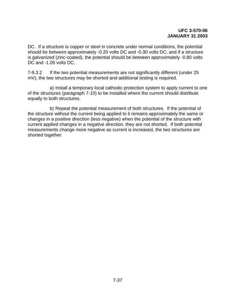
UFC 3-570-06 JANUARY 31 2003
7-37
DC. If a structure is copper or steel in concrete under normal conditions, the potential should be between approximately -0.20 volts DC and -0.30 volts DC; and if a structure is galvanized (zinc-coated), the potential should be between approximately -0.80 volts DC and -1.05 volts DC.
7-9.3.2 If the two potential measurements are not significantly different (under 25 mV), the two structures may be shorted and additional testing is required.
a) Install a temporary local cathodic protection system to apply current to one of the structures (paragraph 7-10) to be installed where the current should distribute equally to both structures.
b) Repeat the potential measurement of both structures. If the potential of the structure without the current being applied to it remains approximately the same or changes in a positive direction (less negative) when the potential of the structure with current applied changes in a negative direction, they are not shorted. If both potential measurements change more negative as current is increased, the two structures are shorted together.
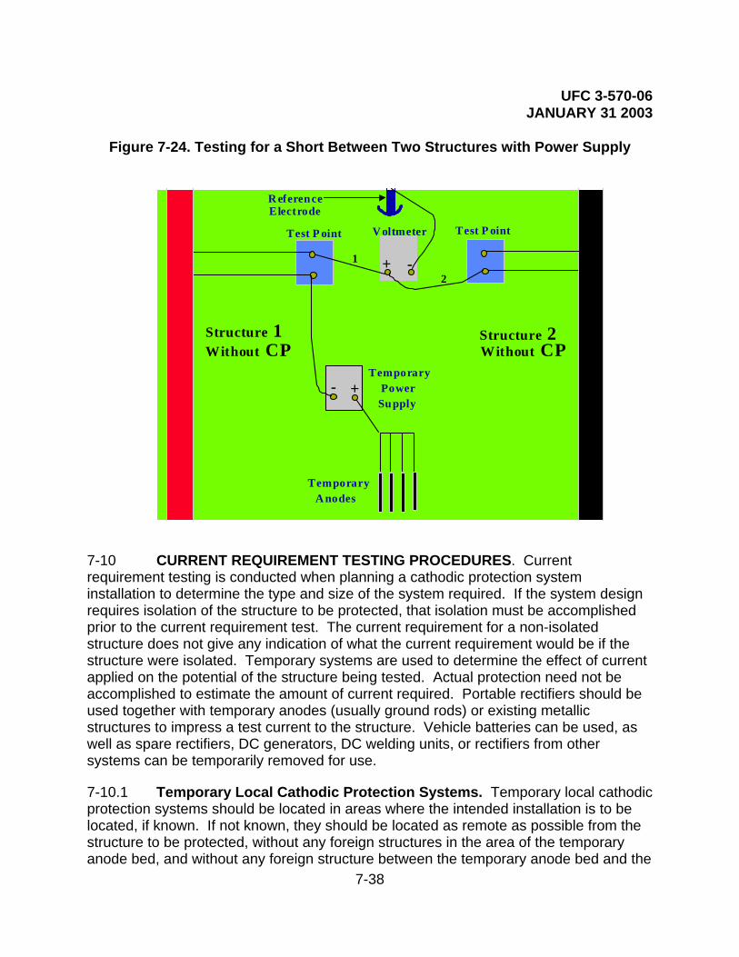
UFC 3-570-06 JANUARY 31 2003
7-38
Figure 7-24. Testing for a Short Between Two Structures with Power Supply
7-10 CURRENT REQUIREMENT TESTING PROCEDURES. Current requirement testing is conducted when planning a cathodic protection system installation to determine the type and size of the system required. If the system design requires isolation of the structure to be protected, that isolation must be accomplished prior to the current requirement test. The current requirement for a non-isolated structure does not give any indication of what the current requirement would be if the structure were isolated. Temporary systems are used to determine the effect of current applied on the potential of the structure being tested. Actual protection need not be accomplished to estimate the amount of current required. Portable rectifiers should be used together with temporary anodes (usually ground rods) or existing metallic structures to impress a test current to the structure. Vehicle batteries can be used, as well as spare rectifiers, DC generators, DC welding units, or rectifiers from other systems can be temporarily removed for use.
7-10.1 Temporary Local Cathodic Protection Systems. Temporary local cathodic protection systems should be located in areas where the intended installation is to be located, if known. If not known, they should be located as remote as possible from the structure to be protected, without any foreign structures in the area of the temporary anode bed, and without any foreign structure between the temporary anode bed and the
TemporaryA nodes
V oltmeter
-+1
2
R eferenceElectrode
- +Temporary
SupplyPower
Test P ointTest P oint
Structure 1 Without CP
Structure 2 Without CP

UFC 3-570-06 JANUARY 31 2003
7-39
structure to be protected.
WARNING: Do not use any metallic structure for a temporary anode that is shorted to the structure being tested. This will result in very large current surges that can cause injury to personnel and damage to equipment. For Navy projects, when conducting work on or near circuits energized lines or parts of equipment operating at or above 50V, utilize work practices identified in OPNAV P-45-117-6-98.
7-10.2 Existing Metallic Structures. Existing metallic structures, such as metal fences, culverts, abandoned pipelines, or abandoned wells can be used as temporary anodes or to supplement installed temporary anodes. If any existing structure is to be used, it should first be tested to see if that structure is shorted to the structure to be tested (see appropriate paragraph in 7-9) The area of the temporary installation should be well scouted to determine if any possible temporary anodes exist or if any foreign structure is in the area. Do not use pipelines or tanks for temporary anodes that would be adversely affected if leaks occurred.
7-10.3 Temporary Anodes. The number of temporary anodes required depends on the available voltage source, the amount of current desired, and the resistivity of the soil. If the number of anodes is doubled, the amount of current is approximately doubled. If the soil resistivity is doubled, the current is cut in half. In very low resistivity soil, two or three anodes may be sufficient, and in very high resistivity soil, a high number of temporary anodes may be required. The amount of current desired depends basically on the quality of the coating on the structure being tested. Very well-coated structures will exhibit a noticeable potential change with a small amount of current (1 or 2 amps), while poorly-coated structures will not exhibit a noticeable potential change except with a large amount of current (10 to 20 amps). If the voltage is doubled, the current is doubled. Consequently, if the voltage source is low, more temporary anodes will be required, if the voltage source is very high, only a few temporary anodes will be required.
7-10.4 Installation of Temporary Anode System. The installation of a temporary anode system is often required to perform current requirement testing. Normally copper ground rods are used. Any metallic ground rod can be used as well as any metallic pipe or conduit. Streams, ponds, rivers, lakes, bays, oceans, or other standing water in the area of the temporary anode location make an ideal location for obtaining a low-resistance-to-earth anode bed. In these wet locations, the ground rods can be simply laid in the water. Normally ground rods are cut in half to make 4- to 5-foot sections. These ground rods (or metallic pipe or conduit), are sharpened and driven into the ground until approximately 0.3 meters (one foot) are above the ground level. These rods should be installed approximately 4.5 to 6 meters (15 to 20 feet) apart to lower the resistance to earth. In high resistivity areas, when higher test current is required, water sprinklers can be used over a period of time to lower the resistance. In extreme cases, an excavation can be made, then small diameter steel pipe can be pushed into the

UFC 3-570-06 JANUARY 31 2003
7-40
earth with a backhoe or bulldozer. This method can also be used to simulate a deeper installation. It is possible to install 9 to 18 meters (30 to 60 feet) in this manner if there are no rock formations.
CAUTION: Do not connect the structure being tested to the positive terminal of the power source. Severe corrosion of the structure may result.
7-10.5 Connections. The temporary anodes all must be connected to the power source positive terminal. The structure being tested must be connected to the negative terminal. For physical strength and low resistance, #6 AWG copper cable or larger must be used and #2 AWG or greater is desired, especially if long runs in either the structure or anode cable are needed. Connections can be made with pipe clamps, test clamps of sufficient size, split bolts, and exothermic welding. All wire and connections must be made to accommodate the voltage and current required for the testing. The normal portable rectifier is 60 volts at 30 amps or 30 volts at 60 amps. Other rectifiers may be over 180 volts or 100 amps.
7-10.6 Before Applying Power. Before any power is applied, it is essential to obtain the as-found potential data of the structure. The native potential must be tested for all locations to be tested during the current requirement test, to obtain the potential shift accomplished by the test current.
7-10.7 Applying Power. Beginning at a low voltage setting, turn power on, ensure the potential shift of the structure is in the negative direction. Gradually increase voltage and current to desired output, while periodically checking potential to ensure a corresponding negative shift as current is increased. If maximum voltage is reached and more current is still required, turn system off and supplement the temporary anode bed (paragraph 7-10.4).
7-10.8 Sufficient Current. Sufficient current is applied when a substantial section of the structure to be tested has achieved a noticeable potential shift or when full protection is achieved. If full protection is achieved, the current requirement is the same as the test current. If full protection is not achieved, further calculations are required.
7-10.9 Calculating Current Requirements. Once the potential shift is ascertained, and the current to get that shift is known, the current requirement can be calculated. If the current is doubled, the potential shift is doubled. Current distribution should be considered: If good current distribution is achieved, a simple mathematical formula will produce the current requirement. If proper current distribution is not achieved, it must be designed into the system. If the design will call for a deeper anode bed, current requirement can be estimated by calculations. If the design is for surface beds, additional cathodic protection systems should be considered and further current requirement testing for additional locations conducted.

UFC 3-570-06 JANUARY 31 2003
7-41
7-10.10 More than One Anode Bed. If a current requirement test includes more than one anode bed location; all current sources should be interrupted simultaneously to measure the potential shift of the structure. The total current requirement is found by adding the current from all power sources together. Always consider proper current distribution and estimate the required current requirement for each individual system.
7-10.11 Completion of Testing. Upon completion of testing, turn all power sources off, disconnect all cables, and remove temporary anodes. For ease of removal of ground rods or small diameter pipes and conduit, use three flat metal bars as shown in Figure 7-25.
Figure 7-25. Removing Temporary Anodes (Ground Rods)
1 2 3
3
1 2
21
3
1 2
3 4
1 2
2
1
3 3
7-11 ELECTROLYTE RESISTIVITY MEASUREMENT. Resistivity is the property of a material that determines the electrical resistance between two points within the material. The most common units of resistivity are ohm-centimeters and ohm/cubic centimeters, which are equivalent. Many factors in the operation of cathodic protection systems are dependent upon the resistivity of the electrolyte. The corrosivity of the environment is generally higher when the resistivity is low. The output of both sacrificial anodes and impressed current anodes is also dependent upon the resistivity of the environment. The resistivity of fresh water and seawater normally does not change sufficiently to affect the operation of cathodic protection systems. However, the resistivity of soil environments depends upon the amount of moisture present and is subject to wide variations. These

UFC 3-570-06 JANUARY 31 2003
7-42
commonly experienced variations in soil resistivity affect the operation of cathodic protection systems, manifesting in variations in structure-to-electrolyte potentials or rectifier outputs measured during routine system inspections. Electrolyte resistivity measurements are taken to determine the cause of improper system operation.
7-11.1 Four-Pin Method. The most commonly used method of measuring soil resistivity is the four-pin method. A current is passed through two electrodes, and a drop in potential through the soil due to the passage of the current is measured with a second pair of electrodes. A specialized instrument is used to supply the current and measure the potential drop. To reduce the influence of any stray currents in the area, the instrument supplies alternating current. The arrangement of electrodes is shown in Figure 7-26.
Figure 7-26. Soil Resistivity by the Four Pin Method (Wenner)
CURRENTFLOW
D = PIN SPACING AND DEPTH OF READINGC = CURRENT PINS
P = POTENTIAL PINS
D
D
CC P P2 2 1 1
The soil resistivity is calculated from the indicated reading by using the following formula:
Resistivity (ohm-cm) = 191.5 × pin spacing (in feet) × meter reading
In this method, the average resistivity of the soil between the two center electrodes to a depth equal to the pin spacing is measured. If the pin spacing is increased, then the average soil resistivity to a greater depth is measured. If the average resistivity increases as the pin spacing increases, then there is a region of higher soil resistivity at depth. If the average soil resistivity decreases with depth, then there is a region of lower soil resistivity at depth. For multipliers for common distances and distances for even multipliers, see Table 7-2.

UFC 3-570-06 JANUARY 31 2003
7-43
Table 7-3. Four-Pin Soil Resistivity Measurement Reading Multipliers
Common Distances Even Multipliers
Distance Between
Rods
Reading Multiplier
Distance Between Rods
Reading Multiplier
2’6” 479 2’7” 500
5’ 958 5’3” 1000
7’6” 1,436 7’10” 1,500
10’ 1,915 10’5” 2,000
12’6” 2,394 13’1” 2,500
15’ 2,872 15’8” 3,000
20’ 3,830 20’11” 4,000
30’ 5,745 31’4” 6,000
7-11.2 Two-Pin Method. In the two-pin method of soil resistivity measurement, the potential drop is measured between the same pair of electrodes used to supply the current. The equipment used to make this type of measurement is often called the “Shepard’s Canes,” after its inventor. As shown in Figure 7-27, the probes are placed 0.3 meters (one foot) apart. If the soil is too hard for the probes to penetrate, the reading is taken at the bottom of two augured holes. The instrument is calibrated for a probe spacing of one foot and gives a reading directly in ohm-cm. Although this method is less accurate than the four-pin method and measures the resistivity of the soil only near the surface, it is often used for preliminary surveys, as it is quicker than the four-pin method.
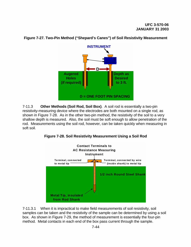
UFC 3-570-06 JANUARY 31 2003
7-44
Figure 7-27. Two-Pin Method (“Shepard’s Canes”) of Soil Resistivity Measurement
INSTRUMENT
D = ONE FOOT PIN SPACING
DDepth asDesiredto 3 ft.
AugeredHoles
(if required)
7-11.3 Other Methods (Soil Rod, Soil Box). A soil rod is essentially a two-pin resistivity-measuring device where the electrodes are both mounted on a single rod, as shown in Figure 7-28. As in the other two-pin method, the resistivity of the soil to a very shallow depth is measured. Also, the soil must be soft enough to allow penetration of the rod. Measurements using the soil rod, however, can be taken quickly when measuring in soft soil.
Figure 7-28. Soil Resistivity Measurement Using a Soil Rod
Metal Tip, insulatedfrom Rod Shank
Term ina l, con nected by wire(ins id e shank) to meta l tip
Contact Terminals toAC Resistance Measuring
InstrumentTerm ina l, con nec tedto m etal tip
1/2 inch Round Steel Shank
7-11.3.1 When it is impractical to make field measurements of soil resistivity, soil samples can be taken and the resistivity of the sample can be determined by using a soil box. As shown in Figure 7-29, the method of measurement is essentially the four-pin method. Metal contacts in each end of the box pass current through the sample.

UFC 3-570-06 JANUARY 31 2003
7-45
Potential drop is measured across probes inserted into the soil. The resistivity is calculated using constants furnished with the particular size of soil box being used. Due to the disturbance of the soil during sampling and possible drying out of the soil during shipment, this method of soil resistivity measurement is less likely to represent true, in-place soil resistivity than an actual field test. To minimize drying out of samples, they should be placed in plastic bags and sealed prior to shipment.
Figure 7-29. Soil Resistivity Measurement Using a Soil Box
C 2
P 2
P 1
C 1
7-12 pH TESTING PROCEDURES. The pH of an electrolyte is a measure of the acidity or alkalinity of the electrolytic solution. pH ranges from 0 to 14 with 0 to 7 being acidic, 7 being neutral and 7 to 14 being alkaline. pH can be measured using several methods. The pH of an electrolyte—the state of active acidity or alkalinity—is a major factor that determines the rate at which metals will corrode. Acid solutions have more hydrogen (H+) ions than hydroxyl (OH-) ions. The electrolyte pH is tested for planning, design considerations, and leak surveys. For steel, the corrosion rate remains fairly constant, from a pH of about 4.5 to a pH of about 10.5. At a pH below 4, the corrosion rate for steel is drastically accelerated. Also, above a pH of 11, the corrosion rate for steel is drastically lower, except for a sharp rise when the pH approaches 14 (not shown in Figure 7-30). For aluminum, acidic corrosion rates are similar to steel, but unlike iron and steel, aluminum also shows accelerated corrosion attack in alkaline electrolytes (above a pH of 8.5) because of a reaction of Al+ ions with OH- ions (see amphoteric, Glossary).

UFC 3-570-06 JANUARY 31 2003
7-46
Figure 7-30. Effect of pH on the Corrosion Rate of Steel
0
0.02
0.04
0.06
0.08
0.1
0.12
1 2 3 4 5 6 7 8 9 10 11 12 13 14
ELECTROLYTE pH
7-12.1 Antimony Electrode Test Method
7-12.1.1 Antimony is a unique metal with the characteristic of a direct relationship between pH and its measured potential. The potential difference or voltage developed between antimony and a copper/copper sulfate reference electrode varies from approximately 0.1 volts DC to 0.7 volts DC due to variations in the pH. Consequently, it can be used to determine the pH of the electrolyte when used together with this reference electrode.
7-12.1.2 The antimony electrode must be cleaned prior to use. As with the copper/copper sulfate electrode, special cleaning procedures must be used. Clean the antimony electrode as per instructions in 7.2.1.1a. Antimony is very brittle; treat it carefully. The antimony tip must be kept smooth, and there must be no rough surface or pits.

UFC 3-570-06 JANUARY 31 2003
7-47
Figure 7-31. Antimony Electrode
ANTIMONY ELECTRODE
BODY
TOP CONNECTIO N
ANTIMONYELECTRODE
VOLTAGE/pH SCALE
7-12.1.3 Place the antimony electrode and the copper/copper sulfate half-cell in contact with the electrolyte and measure the potential difference using a high input resistance voltmeter. The measurement takes several seconds to stabilize. This stabilization is much slower in acid solutions than in alkaline solutions. Avoid taking these measurements with cathodic protection current on. Current flow in the electrolyte will affect the accuracy. If current flow cannot be stopped, place the two electrodes close together, perpendicular to the direction of current flow.
7-12.1.4 To measure for the presence of any current flow in the electrolyte, place one copper/copper sulfate half cell and a second copper/copper sulfate half cell a few inches apart in contact with the electrolyte, and measure the potential difference using a high input resistance voltmeter (paragraph 7-5). Take measurements in several directions. If no current is present, the measurements will read the same; if current is present, the lowest measurement will be where the least amount of current is flowing. Also, if no current is flowing in the electrolyte, the measurement taken should be the same as the measurement taken by placing the two cells tip-to-tip, without touching the electrolyte.

UFC 3-570-06 JANUARY 31 2003
7-48
Figure 7-32. pH Measurement with Electrolyte Current Flow
ELECTROLYTE
CURRENT FLOW CURRENT FLOW
RECOMMENDEDINCO RRECT
7-12.2 Chemical Test Method. Chemical test methods are usually associated with liquid electrolyte samples. Chemical methods of measuring pH involve either the use of pH measuring electrodes or indicators whose colors are dependent on pH. A pH meter measures the difference in potential between a pH-insensitive reference electrode and an electrode whose potential is sensitive to pH. Colored indicators are normally used in the form of pH papers. The paper is wetted with the solution being measured and the resulting color is compared with color standards to determine the pH. When chemical meters or indicators are used to measure the pH of soil, the following procedure is used: a small amount of soil is (one or two tablespoons) placed in a clean container and an equal amount of water is added; after stirring, the mixture is allowed to settle and the pH of the liquid is measured.
7-13 CALIBRATION OF IR DROP TEST SPAN. The IR drop test span is a type of cathodic protection test station that is vital for determination of the direction and magnitude of DC current flowing through a pipeline. In protected pipelines, this information can be used to verify current distribution, look for stray or interference current, and the area of influence of installed rectifiers. In unprotected pipelines, this information can be used to find anodic areas, and to find discharge or pickup areas of stray or interference currents. This method uses the metallic pipeline or cable as a shunt, which is then calibrated and used to measure a millivolt “IR Drop,” from which the current can be calculated. A known amount of DC current is applied to the pipeline and the voltage drop across the length is measured (paragraph 7-13.1). The resistance can be estimated if the size of the pipeline and distance of the test span is accurately known (paragraph 7-13.3). The line current can be determined by the null ammeter method, using a Multi-Combination meter (paragraph 7-13.4). One other method for determining the direction and magnitude of DC current flowing through a pipeline is to use a clamp-

UFC 3-570-06 JANUARY 31 2003
7-49
on milliammeter. This method requires a very specialized piece of equipment, sized to the pipeline, and an excavation or access to the pipeline, for placement of the probe around the pipeline.
The preferred method is to measure the actual resistance of the pipe, using test current. This method does not require knowledge of the pipeline size or wall thickness, and is not affected by variations in the metal due to composition or corrosion, variations of resistance due to temperature, or inaccurate lengths of the test span. The amount of test current required depends on the diameter of the pipeline and the distance of the test span. The larger the pipeline, the larger the amount of current required. The shorter the distance of the test span, the larger the amount of current required.
Figure 7-33. Typical IR Drop Test Span Installation
Voltmeter
-+
Test S tationIR Drop
mV
Pipeline or cable
CAUTION: Do not use an ohmmeter to measure the resistance of the pipeline or cable. The current flowing on pipeline or cable will flow through the meter and damage could result. If that current does not damage the meter, the measurement would not indicate a resistance value. The voltage would be interpreted by the meter as coming from the internal battery instead of the external electrical circuit being measured.

UFC 3-570-06 JANUARY 31 2003
7-50
Figure 7-34. Calibration of an IR Drop Test Span
V oltm eter
- +Test Station
IR DropmV
Pipeline or cable
Ammeter
-+A
- +
DC Power Supply
SwitchAdjustab le
R esis tor
7-13.1 Measurement Circuits. Calibration of an IR Drop test span involves two measurement circuits. The outside circuit comprises an ammeter to measure the current, a DC power supply, an on/off switch and some means of adjustment. A portable rectifier may be used as the current source, switch, and the means of adjustment. The inside circuit is a high input resistance voltmeter (minimum of 10 megaohms), set to the millivolt scale.
Pipelines and cables inherently will have current flowing at all times. Therefore, a change in voltage drop measurement is compared to the amount of test current applied.
• Following all polarities in Figure 7-34, connect all circuit components. Polarity is important for correct determination of the direction of the current flow in the pipeline or cable during subsequent test procedures.
• With the outside circuit switch off, record the mV measurement of the inside circuit.
• Starting at a low current level, turn the outside circuit switch on and adjust current up to the desired test current. Record the measurement of the test current.

UFC 3-570-06 JANUARY 31 2003
7-51
• With outside circuit remaining on, record the mV measurement of the inside circuit.
• Apply this data to the following formulas:
Voltage On - Voltage Off* Resistance = Test Current Applied
Test Current Applied Factor = Voltage Change*
*Voltage change must consider polarity. For example: 4.1 mV ON minus 1.3 mV OFF yields a voltage change of 2.8 mV; whereas 4.1 mV ON minus -1.3 mV OFF yields a voltage change of 5.4 mV (+ mV ON - -mV OFF = +mV ON + mV OFF = Voltage Change).
• Record the resistance of the test span and the calibration factor established. If the temperature of the pipeline or cable remains constant, this calibration factor can be stenciled on the IR drop test station and used for future measurements. If doubt exists or temperatures change, perform the calibration steps each time measurements are taken.
7-13.2 Direction of Current Flow. Direction of current flow is determined by the polarity of the mV reading taken on the inside circuit. For example, using Figure 7-35, a positive IR drop indicates current flow from right to left, while a negative IR drop would indicate current flow from left to right.

UFC 3-570-06 JANUARY 31 2003
7-52
Figure 7-35. IR Drop Test Span, Direction Of Current Flow
V oltm eter- +
Pipeline or cable
+4.32 mV
Voltm eter- +
Pipeline or cable
-4.32 mV
7-13.3 Resistance of the Pipeline. The resistance of the pipeline can be calculated if the distance of the test span is known and the size of the pipeline is accurately known. Resistance joints or insulators cannot be present on the pipeline in the test span. Variations in temperature will adversely affect the accuracy of these calculations.
7-13.3.1 The mV IR drop is measured by using a voltmeter on the mV scale as shown in Figure 7-35. Following all polarities in Figure 7-35, connect the meter to the inside circuit and record the measurement. Polarity is important for correct determination of the direction of the current flow in the pipeline or cable during subsequent test procedures.
7-13.3.2 The resistance is estimated using Table 7-3. The resistance is given in millionths of an ohm (0.000001 ohms) per linear foot of pipeline. This resistance value must be multiplied by the number of feet in the test span (distance in feet of the pipeline between the actual connection points of the test station leads to the pipeline).

UFC 3-570-06 JANUARY 31 2003
7-53
Table 7-4. Estimated Resistance of Steel Pipelines
Nominal Pipeline Size (inches)
Outside Diameter (inches)
Wall Thickness (inches)
Weight per Foot (pounds)
Resistance per Foot (micro ohms)
2 2.375 0.154 3.65 79.20
4 4.500 0.237 10.80 26.80
6 6.625 0.280 19.00 15.20
8 8.625 0.322 28.60 10.10
10 10.750 0.365 40.50 7.13
12 12.750 0.375 49.60 5.82
14 14.000 0.375 54.60 5.29
16 16.000 0.375 62.60 4.61
18 18.00 0.375 70.60 4.09
20 20.000 0.375 78.60 3.68
22 22.000 0.375 86.60 3.34
24 24.000 0.375 94.60 3.06
26 26.000 0.375 102.60 2.82
28 28.000 0.375 110.60 2.62
30 30.000 0.375 118.70 2.44
32 32.000 0.375 126.60 2.28
34 34.000 0.375 134.60 2.15
36 36.000 0.375 142.60 2.03

UFC 3-570-06 JANUARY 31 2003
7-54
7-13.3.3 This data is then applied to the following formula:
mV IR Drop Current =
Resistance
7-13.3.4 The direction of the current flow is determined from the polarity of the mV IR drop reading measured. For example using Figure 7-35, a positive IR drop indicates current flow from right to left, while a negative IR drop would indicate current flow from left to right.
7-13.4 Multi-Combination Meter. The multi-combination meter has the capability of measuring current by the “Null Ammeter Method.” This meter can safely measure line currents less than two amps. Do not use this method in areas over two amps of line current. Stray current variations or other fluctuations in the measurement may make keeping the meter nulled to obtain an accurate and reliable measurement too difficult. This method does not require any information on the length of the test span, diameter of the structure, or the type of metal being tested.
Figure 7-36. Null Ammeter Method, Using the Multi-Combination Meter
- +
Pipeline or cable
FINE --
Multi-Combination Meter
MO D EL B 3 -A-2
COA RSE
RH EO
POLARITY POLARI TY++
IN PUT RESVOLTSVOLTSAM PS
ZER O
MC M
C ONTA CTC HE CK C K T
1.5 V 3 V
INT BTR Y
Inside Circuit (mV)Outside Circu it (A )
Battery(If Requ ired) +- VOLTS
A MPSW ITHC ONTR OLS
+- BI AS
TOLE FTTE RM ZER O
ON /OF F ADJA MPS

UFC 3-570-06 JANUARY 31 2003
7-55
7-14 INTERFERENCE TESTING PROCEDURES. When current flows through an electrolyte, it follows the path of least electrical resistance. If a metal structure is immersed in the current-carrying electrolyte, it is likely to present a low resistance path for the flow of current. At the point where electrons enter the structure from the electrolyte, corrosion will be accelerated. Where electrons leave the structure, corrosion will be reduced. This phenomenon is called cathodic interference. Cathodic interference is commonly encountered on buried structures. Cathodic interference can be detected by electrical measurements and can be controlled. Cathodic protection sometimes causes undesirable effects on structures not connected to the protection system. This occurs because some current is picked up by these “foreign” structures at one point, and in attempting to return to the source and complete the circuit, is discharged at another point. Corrosion occurs at the current discharge point. Current can cause corrosion damage by passing between two structures or across high-resistance joints in the same structure. Sources of interference currents may be constant or fluctuating. Constant current sources have essentially constant direct current output, such as cathodic protection rectifiers and thermoelectric generators. Fluctuating current sources have a fluctuating direct current output, such as direct current electrified railway systems, coal mine haulage systems and pumps, welding machines, direct current power systems, and telluric currents. See paragraph 2-2.4 for explanations and sources of interference current.
Mitigation can usually be accomplished by installing an electrical bond between the unprotected structure (at the location of maximum discharge) and the protected structure. Other mitigation methods include breaking the continuity of the foreign pipeline, coating the foreign pipeline pickup area, coating the protected pipeline in the discharge area of the foreign pipeline, and using galvanic anodes to apply current to the discharge area of the foreign pipeline (and also provide an alternate current discharge point). See paragraph 5-6 for information on interference corrosion control.
7-14.1 Interference from Cathodic Protection Rectifiers. Cathodic protection systems are a major source of stray current on other metallic structures. Structures not electrically connected to the protected structures are considered to be “foreign” structures.” A foreign structure may provide an alternate path for the current flowing from the impressed current anodes to a protected structure. If this path is of sufficiently low resistance, significant current flow will occur. Since there is no metallic return path, the current will discharge from the surface of the foreign structure to the electrolyte to return to its source, resulting in severe corrosion.
Testing requires cooperation by the owners of the structures involved. Such cooperation is best effected by a corrosion coordinating committee; all companies operating underground or underwater structures, and particularly those under cathodic protection, should be members of such a committee. A list of most existing committees may be obtained from the National Association of Corrosion Engineers, P.O. Box 218340 Houston, TX, 77218-8340. Interference testing is usually performed when new
UFC 3-570-06 JANUARY 31 2003
7-56
cathodic protection systems are first installed but is sometimes detected through routine field measurements. Good record keeping is very useful in preventing cathodic interference problems, as any system changes, particularly additions of new buried structures, can be more easily determined when proper records are kept. Interference tests must be made on all structures adjacent to a cathodic protection system to determine effects and to allow design of mitigation measures.
Cathodic interference can be detected by measuring structure-to-soil potentials, potential gradients and current flow (IR drop) with cathodic protection current or resistance bonds on and/or cycled on and off. Structure-to-soil potentials give indications of interference only when measured in an area of current discharge or pickup on the foreign structure. Abnormal or unusual current distribution on a protected structure indicates possible interference on a foreign structure. Current flow (IR drop) readings show the relationship between pickup and discharge areas on a foreign structure. A cathodic protection rectifier output contains a waveform, which results in a pulsating DC signal. Presence of this pulsating DC on foreign structures indicates interference from a rectifier. When conducting current requirement tests or initially energizing impressed current cathodic protection systems, all companies owning underground structures in the area should be notified and coordination tests made with those interested. Current drainage requirements for each structure, from tests at various anode locations, can be determined.
7-14.1.1 The best method to locate interference is to perform a pipe-to-soil potential survey of the foreign pipeline with the source of the interference cycled on and off at specific intervals. The algebraic difference between the “on” and “off” reading (potential shift) gives the interference effect on the foreign structure. The location showing greatest pipe-to-soil potential change in the positive (“unprotected”) direction is called the “critical” or “control” point. This is often at the point where protected and unprotected pipelines cross. The areas showing pipe-to-soil potential change in the negative (“protected”) direction are called “pickup” areas. Presence of a pickup area on a foreign structure indicates that interference is present, and a discharge area exists somewhere on that structure. If metallic continuity exists between the foreign structure and the negative terminal of the rectifier, this is not interference, it is protection, and no discharge area exists (and therefore, by definition is not a foreign structure).
7-14.1.2 If the source of the cathodic interference is not known, it can be detected by measuring structure-to-soil potentials with the cathodic protection current on and by measuring potential gradients. Structure-to-soil potentials give indications of interference only when measured in an area of current discharge or pickup on the foreign structure.
7-14.1.3 Potential gradients are measured by the cell-to-cell test procedures in paragraph 7-5. Taking these measurements along the foreign pipeline may locate the discharge point and pickup areas. The polarity must be ascertained to determine the

UFC 3-570-06 JANUARY 31 2003
7-57
direction of current flow and magnitude. Current will flow in the direction of the discharge point. The magnitude will increase as you near the discharge point. The direction will reverse upon passing a discharge point. The reversal with the highest magnitude is the “control” or “critical” point. The discharge point is usually near the structure, which is causing the interference. The pickup area is usually near the anode system, which is causing the interference. Locating the pickup area is important in locating the source of the interference, since it shows the direction that the current is coming from.
Figure 7-37. Cell-To-Cell Polarity on Foreign Structure
V oltm eter
-+1 2
R eferenceElectrod eElectrod e
R eference
C urrent Flow in th e Earth
D irection of A nodic A rea on Pipeline
Positive (+) Reading
7-14.1.4 Measurement of the current flow (IR drop) on a foreign pipeline can be accomplished if other methods are inconclusive. Current flow (IR drop) readings show the relationship between pickup and discharge areas on a foreign structure. By measuring the current flow on a foreign structure, the direction of the discharge point and pickup areas can be determined. Magnitude indicates seriousness, and increases as the distance to the discharge point decreases. These measurements can be easily accomplished if IR drop test stations already exist or if the pipeline is accessible (comes aboveground or passes through pits). Current is measured at an IR drop test station by the procedures detailed in paragraph 7-13. Current is measured where access to the pipeline is possible using a clamp-on milliammeter (such as the Swain CP AmpClip). The correct size clamp must be used for the pipeline under test. Note: typical clamp-on meters do not work in this application. It must be capable of measuring DC amps, with a range capable of accurate measurement of under 30 milliamps.
7-14.1.5 Abnormal or unusual current distribution on a protected structure indicates possible interference on a foreign structure. Normally, the potential of a protected structure decreases slightly as distance from the anodes increases. At defects in

UFC 3-570-06 JANUARY 31 2003
7-58
coatings, the potential of a protected structure decreases. An increase in potential normally indicates current pickup. If the potential of a protected pipeline increases when crossing a foreign pipeline, interference is likely on that structure. Potential survey of that structure while interrupting the source of current will indicate the presence and magnitude of that interference.
Figure 7-38. Normal and Abnormal Potentials of Protected and Foreign Pipelines
Anode BedLocation
Foreign PipelineCrossing
N ormalPotentialSurvey
A bnormalPotentialSurvey
ProtectedPipelinePotentials
ForeignPipelinePotentials
NormalPotentialSurvey
Potential Survey of Pipelines for Interference
Pickup Area
Discharge Area
-1
-.9
-.8
-.7
-.8
-.6
-.4
-.2
A bnormalPotentialSurvey
7-14.1.6 A cathodic protection rectifier output contains a waveform, which results in a pulsating DC signal. This signal can be located using a pipe locator capable of following a 120 cycles per second signal (such as the Pipe Horn, Model 200 FDAC, in rectifier mode). Presence of this signal indicates presence of interference on the foreign structure. Combining this method with a current interrupter on suspected sources of the interference will quickly locate the source of the interference. Signal strength can sometimes be used to indicate the direction of the discharge and pickup areas. Normally, signal strength will increase in the direction of the discharge point. This may not occur with multiple discharge areas.
7-14.1.7 Another method of interference testing involves using an experimental drainage bond between structures. Proper drainage can be determined by trial-and-error, using a variable resistor to alter drainage current. Required drainage current can also be computed from test data. When the same owner maintains the protected structure and the foreign structure, this method may be easily used. The source of interference is cycled on and off at specific intervals and the bond resistance is adjusted until no potential shift occurs on the foreign structure. When site conditions warrant, the bond may be sized to apply partial or full protection to the foreign structure. If the

UFC 3-570-06 JANUARY 31 2003
7-59
foreign structure is small or well coated, and the protected structure is poorly coated, this option may be taken when sufficient CP current is still available to maintain protection on the protected structure.
7-14.2 Interference from Variable (Fluctuating) Sources. While interference testing determines effects of steady stray currents, another type of stray current survey analyzes fluctuating stray currents. Fluctuating or periodic changes in structure-to-electrolyte voltage values and unusual or fluctuating currents are indicative of stray currents. Stray currents may affect structures just as cathodic protection does. Structures may be protected or damaged by stray currents, depending on whether current is flowing to or from the structure. Such analysis is specialized and requires study to master all techniques. The basic principles are the same as in the previous paragraph (7-14.1). The difference is that the stray current is not present all the time. The simultaneous use of data loggers or recording devices at many points on the foreign structure will indicate the same information as above. Locating the discharge point(s) and pickup areas is still crucial. In this case, determining the time of the interference is also crucial.
7-14.2.1 All the basic measurements can be used in studying fluctuating stray currents. Perhaps the most informative are measurements similar to those used in interference testing: structure-to-electrolyte potentials and IR drops along structure or electrolyte. Methods of analysis, however, are different, and specialized equipment is used. The major concern in performing a stray current survey is to find out the degree of damage and determine the source of the currents.
7-14.2.2 Measurement of the foreign pipeline potentials is commonly used to determine the pickup and discharge areas. Using data loggers or recording devices, many locations on the foreign structure are monitored simultaneously. This data is then charted to analyze for the presence of interference. When the exact moment of interference is determined, all potential readings taken at that instant are used to determine the discharge and pickup points. Data taken is used to locate areas for taking additional data. Once gathered, this data is used exactly like the data for cathodic interference detailed in paragraph 7-13. Abnormal potentials on other structures may also be used for further analysis. Once the pickup area and time is determined, the source of the current may be located (see paragraph 2-2.4 for sources of fluctuating stray currents).
7-14.2.3 Another method of finding these points is through current measurements. To determine the pickup and discharge points in fluctuating stray current areas, data from several test points are plotted over a period of time. Current values on the several locations on the foreign structure (recorded from IR drop test spans or a clamp-on milliammeter) are plotted over a period of time. The current must be measured at several points simultaneously, sufficient readings being made to cover the range of variation of the current (usually at least 24 hours). By analyzing the current direction

UFC 3-570-06 JANUARY 31 2003
7-60
and magnitude at the time the interference is occurring, the relationship and direction of the pickup areas and discharge areas can be determined. Once the time of interference is known, the area of pickup can be searched for possible sources of the current pickup (see paragraph 2-2.4 for sources of fluctuating stray currents). Outside of the necessity of taking simultaneous readings due to the fluctuating current, this method is the same as conventional line current measurements.

UFC 3-570-06 JANUARY 31 2003
A-1
APPENDIX A PART 1
SAMPLE BASE CORROSION CONTROL OPERATING INSTRUCTION (AIR FORCE)
123rd Engineering Squadron ESOI 32-1054Sample Air Force Base, XX ZIP+4 7 Feb 1995
Air Force Facilities
CORROSION CONTROL
The purpose of this directive is to outline responsibilities andprocedures required to establish and conduct a continuing andrecurring Corrosion Control Program for Sample AFB, XX.
1. Criteria. This directive is applicable to all EngineeringSquadron personnel involved, directly or indirectly, in thedevelopment and maintenance of an effective Corrosion ControlProgram.
2. Responsibility. The Air Force Civil Engineering SupportAgency (AFCESA) has overall responsibility for the Air ForceFacility Corrosion Control Program.
a. Headquarters (MAJCOM) is responsible for the functionaladequacy of Air Force new construction.
b. Headquarters (MAJCOM) is responsible for the command’sCorrosion Control Program and will ensure all installationswithin the command develop, establish, and maintain an effectivecomprehensive Corrosion Control Program with personnel adequatelytrained to carry out their responsibilities.
c. Base Engineering must establish and maintain a CorrosionControl Program for each activity within the squadron at SampleAFB. The Chief of the Engineering Flight and the Chief ofOperations Flight will work together to assign the Base CorrosionControl Engineer (BCCE). They will also appoint a BaseIndustrial Water Treatment Engineer and a Base ProtectiveCoatings Engineer as required. The Chief of Operations willappoint the cathodic protection and industrial water treatmentcraftsmen in consultation with the Chief of InfrastructureSupport.
d. The BCCE is responsible for the overall management ofthe base Corrosion Control Program and coordinates this program
__________Supersedes CESOI 91-27, 3 Mar 90OPR: 123rd ES/XXX (Name of Individual)DISTRIBUTION F

UFC 3-570-06 JANUARY 31 2003
A-2
with the Chief of Operations Flight, Chief of MaintenanceEngineering Element, Chief of Infrastructure Support Element,cathodic protection craftsmen, industrial water treatmentcraftsmen, protective coatings personnel, and other appropriatefunctions within the operations flight. The BCCE will establishand chair a Base Corrosion Control committee that will meet atleast quarterly. Minimum participants will be:
(1) Chief of Operations(2) Chief of Maintenance Engineering(3) Chief of Infrastructure Support(4) Lead craftsmen in Mechanical, Electrical,
Structural, and Sanitation(5) Lead planner(6) Others as appropriate.
e. Engineering Construction Management will monitor everyphase of coatings operations to include SABER contract andgeneral contract operations. For all other corrosion workwhether contract or in-house, this office will provide thecoatings test equipment and expertise to evaluate work andinvestigate coating failures.
3. Reference: AFI 32-1054, Attachment 2, for directives andguidance that have an impact on corrosion control engineering.
4. Overall Procedures:
a. Work Procedures: The following procedures will apply tothe Sample Air Force Base Corrosion Control Program.
(1) The Civil Engineer (CE) will appoint, by letter, acorrosion control engineer with the advice of the Chief ofEngineering, Chief of Operations, and Chief of MaintenanceEngineering. Send a copy of this letter and subsequent updatesto MAJCOM/XXX for the MAJCOM corrosion control engineer.
(2) Chief of XXX will assign corrosion control dutiesto the engineer appointed by the CE and ensure the appointeereceives adequate training to carry out these responsibilities(see Attachment 1, AFI 32-1054).
(3) Chief of Operations will appoint at least xxcathodic protection craftsmen and other corrosion controlcraftsmen from the appropriate shops as he/she deems necessary tofacilitate corrosion control duties. Personnel involved incorrosion control duties should receive adequate training on anannual basis and be appointed in writing. A file containing acurrent roster of corrosion control personnel will be in theOperations Branch and will contain training status and trainingprogram information. Send updated copies of appointment letters

UFC 3-570-06 JANUARY 31 2003
A-3
for corrosion control duties to the BCCE.(4) The BCCE will manage the overall Engineering
Squadron Corrosion Control Program. He will:
(a) Program developments and managementprocedures.
(b) Review engineering drawings andspecifications developed under base direction for adequacy ofcorrosion control.
(c) Review engineering drawings for MilitaryConstruction Program (MCP) projects for adequacy of corrosioncontrol.
(d) Maintain base corrosion control records.
(e) Retain logs compiled by appropriate shops, tobe collected at the end of the calendar year. Cathodicprotection craftsmen shall retain and log readings on theappropriate forms during the year and forward to the BCCE at theend of the calendar year.
(f) Review corrosion records monthly.
(g) Under MAJCOM guidance, complete a closeinterval survey every five years.
(h) Include the requirements of AFI 32-1054 andcriteria established by MAJCOM in the Corrosion Control Program.
(i) Establish a cathodic protection system masterplan and show all installed rectifiers, ground beds, teststations, and magnesium anodes. Update the maps to show anymodifications made on the systems. Indicate the location ofneighboring structures.
(j) Conduct an annual cathodic protectionperformance survey with a cathodic protection craftsman. Thiswill include:
1. Structure-to-soil potential measurements,on all pipelines (building gas service risers), both sides ofisolating insulation, hydrant outlets in POL systems, and surfaceand underground tanks.
2. Internally inspecting water storagetanks.
3. Updating the Cathodic Protection Annual

UFC 3-570-06 JANUARY 31 2003
A-4
Performance Booklet and submit it to MAJCOM/XXX for review.
4. Updating the cathodic protection programrecord.
5. Determining actions required to providecomplete protection and prepare maintenance action sheets.
(k) Ensure the necessary corrosion tests andsystem examinations are performed on boiler water.
(l) Ensure the treatment equipment is adequateand working for cooling water.
(m) Investigate all reported leaks and corrosionfailures, determine cause of failure and corrective actionrequired to prevent recurrence. Do not restrict viewpoint tofluid carrying systems or high-value steel structures, expand toinclude other items, such as metal roofing and flashing, thatleak and cause water damage to structures and contents.
(n) Maintain data on corrosion failures andrecord each location where an underground failure occurs on abass layout map.
(o) Analyze date for patterns which indicatemajor problem areas.
(p) Assist the Infrastructure Support Element inprocuring proper cathodic protection test equipment.
(q) Assist Engineering Construction Management inprocuring necessary paint inspection equipment.
(r) Assist other corrosion control craftsmen inprocuring leak detection equipment, test instruments, chemicaltreatment equipment and consumables as necessary to conduct aneffective Corrosion Control Program.
(s) Perform economic analysis of corrosioncontrol measures.
(t) Arrange for technical assistance asrequired through MAJCOM.
(u) Call corrosion control committee meetings,establish agenda items and ensure coordination of all corrosioncontrol activities through this committee.
(5) Cathodic protection craftsmen will perform tests

UFC 3-570-06 JANUARY 31 2003
A-5
consisting primarily of electrical measurements to indicate thecondition of system components. Maintenance duties will include:
(a) Rectifier checks for current and voltageoutput, meter function, proper operation, and adjustment tomaintain the required current.
(b) Structure-to-soil potential measurements atthe four test points established by annual surveys of impressedcurrent systems.
(c) Structure-to-soil potential measurements andcurrent output of anode systems, and the addition of anodes asrequired for complete protection.
(d) Minor system repairs.
(e) Submitting maintenance requirements for majorwork.
(f) Entering operational data in appropriate logsand forwarding to the BCCE for filing and maintenance.
(g) Conducting an annual cathodic protectionsurvey under the BCCE.
(h) Procure and retain custody of instrumentsauthorized and required in routine maintenance of installedcathodic protection systems.
(6) Engineering Construction Management will keepevery phase of coating operations under surveillance. This willinclude:
(a) Coating type, thickness, and bonding.
(b) Checking the above against specifications.
(c) Checking surface preparation prior to coatingapplication.
(d) Documenting subsequent coating performance.
(e) Reporting any damage found duringinspections.
(f) Assuring repair of reported damage byrecommended methods.
(g) Procure and retain custody of test equipmentnecessary for inspection (film thickness gauges, blasting

UFC 3-570-06 JANUARY 31 2003
A-6
standards, holiday detector, paint test kit).
(h) Coordinate requirements for coatingoperations with the BCCE, SABER contractor, and generalcontractors as required to ensure adequate corrosion controloperations.
(i) Forward all test data to the BCCE for filingand retention.
(7) Corrosion control craftsmen will perform tasksnecessary to accomplish corrosion control to the maximum extentpossible in their areas of responsibility. Areas that mayrequire a corrosion control craftsman include:
(a) Potable water systems and treatment corrosioncontrol craftsman will (OPR: Infrastructure Support Element):
1. Perform raw analysis every three years.Accomplish by contract if capability not available on base.
2. Record treatment performed daily on AFForm 1461, Water Utility Operating Log.
3. Determine and record consumption monthly.
4. Maintain water treatment logs in Facility62515, Water and Waste Building, for review by the BCCE.
5. Use AF Form 1687, Leak/Failure DataRecord, as appropriate and forward to the BCCE.
6. Monitor water distribution systemspressure meters hourly to determine possible water leaks.
(b) Boiler water systems and treatment corrosioncontrol craftsman will (OPR: Zonal Maintenance Elements):
1. Maintain complete records of boiler watertreatment daily on AF Form 1459, Water Treatment Operating Logfor Steam and Hot Water Boilers. This will include:
a. Internal Treatment (chemicals).b. External Treatment (deaerators,
softeners, decarbonators).
2. Test make-up water, quantity and qualitymonthly.
3. Check for leaks in steam valves, flanges

UFC 3-570-06 JANUARY 31 2003
A-7
and unions in boiler plants daily.
4. Test heat exchangers for leaks monthly.
5. Check pressure and temperature of de-aerating heater daily.
6. Determine conductivity of returncondensate daily as a minimum, hourly for large plants.
7. Have condensate corrosion tests performedmonthly.
8. Test ion exchanger output quality dailyas a minimum, more often if required.
9. Check mechanical rooms with hot waterheat exchangers for signs of corrosion problems semiannually.
10. Check all tanks annually.
11. Check boiler plant piping systems daily.
12. Use AF 1687, Leak/Failure Data Record,as appropriate and forward to the BCCE.
13. Procure and retain custody of testequipment necessary for corrosion control testing of boiler watersystems.
(c) Cooling water systems and treatment corrosioncontrol craftsman will (OPR: Zonal Maintenance Elements):
1. Maintain complete records of coolingwater treatment as required. Use AF Form 1457, Water TreatmentOperating Log for Cooling Tower Systems as a minimum. Maintainthese records in the shop for review by the BCCE.
2. Check cooling towers for algae and scalebuild-up monthly.
3. Together with the BCCE, ensure monthlythat treatment equipment is adequate and is working.
4. Calculate cycles of concentration andmaintain according to survey recommendations monthly.
5. Procure and retain custody of testequipment necessary for corrosion control testing of coolingwater systems.
UFC 3-570-06 JANUARY 31 2003
A-8
6. Use AF Form 1687, Leak/Failure DataRecord, as appropriate and forward to the BCCE.
(d) Protective coating corrosion control is byService Contract (OPR: Maintenance Engineering):
1. Update painting records as required.
2. Report any damage found to the BCCE forsubsequent repair or recommendations.
3. Ensure Service Contractor appliessuitable coatings to the structure and environment. Also ensurecompatibility with previously applied coatings and otherprotective methods, such as cathodic protection.
4. Together with the BCCE, inspect coatingson all high cost steel structures semiannually.
5. Coordinate closely with MaintenanceEngineering to ensure compliance with paragraphs 4a(6)(a) through4a(6)(i).
6. Use AF Form 1687, Leak/Failure DataRecord, an appropriate and forward to the BCCE.
(e) Water distribution systems corrosion controlcraftsman will (OPR: Infrastructure Support Element):
1. Perform leak/failure inspections asrequired. Notify the BCCE of leaks and failures in the waterdistribution systems.
2. Use AF Form 1687, Leak/Failure DataRecord, for all leaks detected in the water distribution systemsand forward to the BCCE.
3. Coordinate with the water systems andtreatment corrosion control craftsman (Water & Waste) on possiblewater distribution leaks.
4. Procure and retain custody of testequipment necessary for leak detection in the water distributionsystem.
(f) POL/JP4 distribution systems corrosioncontrol craftsman will (OPR: Infrastructure Support Element):
1. Perform leak/failure inspections as

UFC 3-570-06 JANUARY 31 2003
A-9
required. Notify the BCCE of leaks and failures in the POL/JP4distribution systems.
2. Use AF Form 1687, Leaks/Failure DataRecord, for all leaks detected in the POL/JP4 distributionsystems and forward to the BCCE.
3. Procure and retain custody of testequipment necessary for leak detection in the POL/JP4distribution systems.
b. Record Procedures. Maintain the following records tosupport the Corrosion Control Program at Sample AFB as indicated.
(1) Personnel Files: Operations Flight and the BCCEwill maintain a current roster of corrosion control craftsmen.File will contain training status and training programinformation.
(2) Equipment Information: BCCE will maintain a listof corrosion control equipment with operational status. Thisfile will contain the following information:
(a) Manufacturers’ data on installed equipment.
(b) Lists of repair parts.
(c) Names and addresses on sources and parts.
(d) Current price lists.
(e) Repair, operating, and maintenanceinstructions.
(3) System Information: BCCE will maintain files onwater treatment systems, cathodic protection installations,protective coatings, and all other systems of corrosion control.This file will include:
(a) Standard design and constructionspecifications.
(b) Cross reference listing of projectscontaining corrosion control.
(c) Shop and as-built drawings updated to showmodifications.
(d) Cathodic Protection Program Records

UFC 3-570-06 JANUARY 31 2003
A-10
(e) Cathodic Protection Annual PerformanceBooklet.
(4) Failure Records: BCCE will maintain records ofcorrosion control damage and facility failures. Forward to theBCCE the AF Form 1687, Leak/Failure Data Record, after completionby the appropriate corrosion control craftsman. The BCCE willfurther investigate the failure as appropriate. The BCCE willindicate the location of the leak or failure on the base layoutmap. The BCCE will record the corrective maintenance, repair, orapplied corrosion control measures, including costs.Distribution of this form will be one copy to each of thefollowing:
(a) The BCCE’s record.
(b) The facility jacket.
(c) The Cathodic Protection Annual PerformanceBooklet.
(d) The MAJCOM corrosion control engineer.
(5) Survey Records: The BCCE will maintain acontinuous and current file of corrosion survey results andrecommendations. These records will contain:
(a) Command corrosion analysis team surveys,recommendations, and implementation plans.
(b) A-E surveys and recommendations.
(c) Water and gas leak surveys.
(d) AF Form 1688, Annual Cathodic ProtectionPerformance Survey.
(6) Test Results. The BCCE will maintain records oftest data and results. This file will contain:
(a) Boiler water analysis.
(b) Corrosion tester/coupon reports.
(c) Interference testing record sheets.
(d) Area of Influence Test Worksheet, using amodified AF Form 1688, Annual Cathodic Protection PerformanceSurvey.

UFC 3-570-06 JANUARY 31 2003
A-11
(e) AF Form 1689, Water Tank Calibration.
(7) Operational Logs: The BCCE will periodicallyreview all operational logs. Distribute the following logs asindicated:
(a) The NCOIC, Water & Waste, will complete AFForm 1461, Water Utility Operating Log, and maintain it inBuilding 417. Upon request from BCCE, the NCOIC will forward acopy for review.
(b) The cathodic protection craftsman willcomplete AF Form 491, Cathodic Protection Operating Log forImpressed Current System, and AF Form 1686, Cathodic ProtectionOperating Log for Sacrificial Anode System, and forward copies tothe BCCE for inclusion in:
1. The cathodic protection facility jacketfolder.
2. The Cathodic Protection AnnualPerformance Booklet.
(c) HVAC boiler water systems and treatmentcorrosion control craftsman will complete AF Form 1459, WaterTreatment Operation Log for Steam and Hot Water, and forward acopy to the BCCE.
(d) The cooling water systems and treatmentcorrosion control craftsman will forward one copy of all recordsmaintained by their function to the BCCE.
(8) Maintain equipment maintenance records andmaintenance action sheets (MAS) according to AFI 32-1031,Operations Management. Keep a copy of the AF Form 1841,Maintenance Action Sheet, in the facility jacket folder forcorrosion control activities.
(9) Cost Records: The BCCE will maintain continuousrecords. This file will include:
(a) Failure costs from AF Form 1687, Leak/FailureData Record.
(b) All other corrosion control costs, to includeprojects containing corrosion control measures. These costs willinclude initial installations, recurring maintenance, andsurveys. It is especially important to include all repair byreplacement projects and work orders to historically record thelife-cycle costs of the base infrastructure.

UFC 3-570-06 JANUARY 31 2003
A-12
(10) Requirements and Management Plans: The BCCE willinclude corrosion control items for each system and component tominimize life cycle costs.
Summary of Changes:
1. Internal reorganization under objective squadron.
2. Paint Shop work now performed by service contract andadministered by Maintenance Engineering.

UFC 3-570-06 JANUARY 31 2003
A-13
APPENDIX A PART 2
INSTRUCTIONS FOR COMPLETING AIR FORCE FORM 491
1. Entries on AF Form 491 must be made on a monthly basis.
2. No readings of the structure-to-soil potentials are to betaken where the electrode is in contact with frozen ground.
3. Readings are to be made with the authorized meters only (seenote under item 10 of instructions).
Item 1. Installations. Enter the official name and location ofthe installation as: ROBINS AFB, GA. Do not abbreviate or useunit designations.
Item 2. Year. Enter the calendar year.
Item 3. Protected Structure. Enter the name of the protectedstructure and its number as shown on USAF Real Property Report(RCS: HAF-PRES(SA)7115) as “Water Tank 603” or “Gas piping systemfamily housing.”
Item 4. Rectifier Number. Enter the number of the rectifier asassigned by the corrosion engineer. Number are consecutivestarting with number 1 and are conspicuously shown on therectifier.
Item 5. Rectifier Data. (from nameplate).A. Manufacturer: Enter full name and address of
manufacturer.B. Model Number: Enter model number as shown on
nameplate.C. Serial Number: Enter serial number as shown on
nameplate.D. AC Rated Capacity: Enter AC voltage and phase.E. DC Rated Capacity: Enter DC voltage and amperage.F. Date Installed: Enter date installed. This infor-
mation is to be obtained from the base corrosion engineer.Where no detailed information is available, estimate and enterapproximate date.
Item 6. Ground Bed Data:A. Anode Material. Enter the name of the material and
alloy designation, if known, as “graphite,” “aluminum 3003,” or“high-silicon cast iron.”
B. Size of Anode. Enter the dimensions or the standardsize designation as 1½" x 60", or 3" x 60".
UFC 3-570-06 JANUARY 31 2003
A-14
C. Number of Anodes. Enter number of anodes.D. Type of Backfill. Enter the type of backfill usedaround the anodes as “coke breeze” or “natural soil.”E. Date Installed. Enter the date when the anode bedwas installed.
Item 7. Location Reference Drawing Number. Location of rectifierand test stations as recorded on the drawings. Enter thenumber of the drawing and the sheet number for easyreference.
Item 8. Current Required: Enter the amount of current needed togive complete protection and the date such determinationwas made.
Item 9. Location and Description: Enter a brief description ofthe location of the rectifier and tests points in orderto easily find them, as “west leg of tower,” or “pole468-1,” “300 feet east of the side entrance of building1450.” The test points indicated here and in items 10Hthrough 10K for recording values are the same testpoints.
Item 10. Operating Record:Column A: The month tests are performed.Column B: Enter the date of the month.Columns C through G are readings of direct current onlyand must be taken with authorized instruments that arerecently calibrated.Columns C and E: Enter the DC voltage as found andbefore any adjustments are made in Column C. At the sametime, read the amperage as found and enter it in columnC.Columns D and F: Adjust voltage until the required DClevel is reached (item 8). Enter the voltage obtained incolumn D and amperage value obtained in column F.Column G: The corrosion engineer must compute thecircuit resistance using ohms law and enter the value incolumn G.
Resistance =voltage as adjusted
amperage as adjusted
Column H: Test point 1 (referred to as “maximumpotential area”) must be determined using data obtainedfrom the annual performance survey. This point islocated closest to the ground bed and is to be taken overthe structure in that area. Enter this value in column
UFC 3-570-06 JANUARY 31 2003
A-15
H. Care must be taken to read the correct polarity.Columns I through K: Test points 2,3, and 4 are thelowest potential points of the protected structure beingprotected by the rectifier. These test points must bedetermined using data obtained from the annualperformance survey. They are subject to change asdirected by the corrosion engineer. Enter the valuesfound for the appropriate points.Column L: State whether soil is wet, moist, dry, orpowdery. NOTE: For the testing of structure-to-soilpotentials, only authorized multimeters andpotentiometers will be used. For structure-to-electrolytepotential readings, the potentiometer circuit must beused. If the ground is frozen, do not take readings andstate so in column L by entering “GF.”
Signature: Each monthly log must be signed by the cathodicprotection technician (CPT) and the base corrosion engineerbefore submission to higher headquarters.
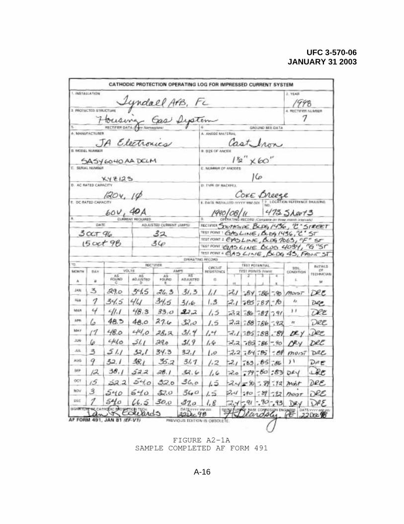
UFC 3-570-06 JANUARY 31 2003
A-16
FIGURE A2-1ASAMPLE COMPLETED AF FORM 491

UFC 3-570-06 JANUARY 31 2003
A-17
FIGURE A2-1BSAMPLE COMPLETED AF FORM 491

UFC 3-570-06 JANUARY 31 2003
A-18
APPENDIX A PART 3
INSTRUCTIONS FOR COMPLETING AIR FORCE FORM 1686
1. Entries on AF Form 1686 will be made biannually, or moreoften if required by the parent command.
2. No readings of the structure to soil potentials are to takenwhere the ground is frozen.
3. Readings are to be made with the authorized meters only.
Item 1. Installations. Enter the official name and location ofthe installation as: MARCH AFB, CA. Do not abbreviate or useunit designations.
Item 2. Year. Enter the calendar year.
Item 3. Protected Structure. Enter the name of the protectedstructure and its number as shown on USAF Real Property Report(RCS: HAF - PRE(SA)7115) such as “Underground Gas PipelineCapehart Hsg Nr 220.”
Item 4. Test Station Number. Enter the number of the teststation where the reading of the potential is to be taken. Teststations should be numbered consecutively starting with number 1for the entire base.
Item 5. System Data:A. Number of Anodes. From record, find the number of
existing anodes on this system and enter it on the form. Also,note under remarks on back of form if any new anodes wereinstalled during the last year and how many.
B. Number of Test Stations. Enter here the total numberof test stations for this piping system. List the test stationsby number.
Item 6. Anode Data:A. Type. Enter the name of the anode, trade name, its
manufacturer, and the name of the material, as “magnesium H-1” or “zinc.”
B. Size. Enter the dimensions or the standard sizedesignations as “2" by 5' long” or “17 lb,” or “32 lb.”
C. Type of Backfill. Enter the type of backfill usedaround the anodes as “prepackaged,” “bentonite,” “coke breeze,”or “none.”
D. Location Description. Enter a brief description of

UFC 3-570-06 JANUARY 31 2003
A-19
the location of the anode so that it can be located easily, as“gas line 50' W to 10' N of building 2263.”
E. Date Installed. Enter date of installation. Thisdate will be supplied by the corrosion engineer. Where nodetailed information is available, estimate and enterapproximate date.
Item 7. Operating Record:Column A. The month tests are performed.Column B. Enter the date of the month of the survey.Column C. Structure-To-Soil Potentials At Test Station
(Volts). This reading will usually be taken at the teststation(s) of the system. Where no test stations are installed,readings must be taken at point as directed by the corrosionengineer. Enter the value found in column C.
Column D. Structure-To-Soil Potential Between Anodes(Volts). This is the potential-to-ground of the structurehalfway between two anodes (or the most remote point of astructure from the anode protecting it). It is important toknow how far the protection of an anode extends. Enter thevalue in column D.
Column E. Anode-To-Soil (Volts). This readingrepresents the open circuit voltage of the anode with thestructure (load) disconnected. Enter the reading in Column E.
Column F. Anode-To-Structure (Milliamps). Connect themilliamp meter between the structure and anode at the teststation and enter the value in column F.
Column G. Soil Conditions. State whether soil is wet,moist, dry, or powdery. The condition of soil is approximately1 foot below surface. If the ground is frozen, do not takereadings and so state by entering “GF.”
Column H. Initials of Technician. The initials of thecathodic protection technician (CPT) must be shown in thiscolumn.
Signatures: Each log must be signed by the (CPT) and the basecorrosion engineer before submission to higher headquarters.

UFC 3-570-06 JANUARY 31 2003
A-20
FIGURE A3-1A
SAMPLE COMPLETED AF FORM 1686

UFC 3-570-06 JANUARY 31 2003
A-21
FIGURE A3-1B
SAMPLE COMPLETED AF FORM 1686

UFC 3-570-06 JANUARY 31 2003
A-22
APPENDIX A PART 4
INSTRUCTIONS FOR COMPLETING AIR FORCE FORM 1687
FILL IN THE BLOCKS WITH THE FOLLOWING INFORMATION (blockheadings are in bold lettering):
REPORT CONTROL SYMBOL: Not Applicable (N/A).
INSTALLATION: Enter the official name and location of theinstallation such as, “Fairchild AFB, WA.” DO NOT USEDESIGNATIONS OR ABBREVIATIONS SUCH AS, “FAFB.”
FACILITY NUMBER: Enter the number of the facility, such as“Building 1376”or “Water Tank 904.”
AREA/SPECIFIC LOCATION: Enter the area, such as “North side ofbuilding 1376, 50' west of the fire hydrant.”
DRAWING NUMBER: Show drawing number of the map upon which thisleak is located for the purpose of recording installation leakhistory.
FLUID TRANSPORTED OR STORED: Mark (x) in the block for the typeof fluid or fill in the other (specify) block with theappropriate name of the fluid.
AVERAGE TEMPERATURE OF FLUID: Enter the average temperature indegrees Fahrenheit.
DATE: Enter the date of the structure (i.e., pipe, valve ortank) installation.
DESIGN LIFE: Enter the number of years (life expectancy)of thestructure.
TYPE AND LOCATION OF STORAGE FACILITY OR TRANSPORT: Mark (x) inthe appropriate block or fill in the other (specify) block forthose not listed.
DATE LEAK/FAILURE DISCOVERED: Enter the appropriate date, day,month and year such as, “1 Feb 98.”
SIZE/DIAMETER: Enter the size of the storage facility ortransport such as, 6" or 500 gallon capacity.
LINE OR TANK DEPTH: Enter the depth of the corroded structure.

UFC 3-570-06 JANUARY 31 2003
A-23
CAUSE OF FAILURE: Mark (x) in the appropriate block or enterthe information in the block for other (specify).
METAL(S) AND/OR SUBSTRATE AFFECTED: Write in the appropriatetype of metal or substrate.
SPECIFIC ACTION TAKEN TO REPAIR LEAK: Write in the specificaction taken to make repairs and identify the specific area(s)affected on the drawing.

UFC 3-570-06 JANUARY 31 2003
A-24
SECOND PAGE – (CORROSION ENGINEER DIRECTS)
CATHODIC PROTECTION: Mark “x” if applicable.
TYPE SYSTEM: Mark “x” in the appropriate block.
PROTECTIVE COATINGS: Mark “x” if applicable.
COATINGS SYSTEM USED: Specify the type of coating and/or wrapused if applicable.
INDUSTRIAL WATER TREATMENT: Mark “x” if applicable.
TYPE SYSTEM: Mark “x” in the appropriate block.
AS FOUND CONDITION: Describe the condition of the structure whenthe problem was discovered.
AS LEFT CONDITION: Describe the work accomplished to repair thestructure.
SPECIFIC ACTION TAKEN TO REPAIR CAUSE OF LEAK OR FAILURE:Describe the measures taken to prevent a reoccurrence of thisproblem.
SIGNATURES: The form must be signed by the (CPT) and the basecorrosion engineer before submitting to a higher authority.

UFC 3-570-06 JANUARY 31 2003
A-25
FIGURE A4-1A SAMPLE COMPLETED AF FORM 1687

UFC 3-570-06 JANUARY 31 2003
A-26
FIGURE A4-1B
SAMPLE COMPLETED AF FORM 1687

UFC 3-570-06 JANUARY 31 2003
A-27
APPENDIX A PART 5
SAMPLE COMPLETED AIR FORCE FORM 1688
FIGURE A5-1SAMPLE COMPLETED AF FORM 1688

UFC 3-570-06 JANUARY 31 2003
A-28
APPENDIX A PART 6
FIGURE A6SAMPLE COMPLETED AF FORM 1689
UFC 3-570-06 JANUARY 31 2003
A-29
APPENDIX A PART 7
GUIDELINES FOR PREPARING THE CATHODIC PROTECTION ANNUAL PERFORMANCE BOOKLET
The annual survey must be submitted in a hard cover, three-ringbinder. The binder will contain basic information and the annualsurvey data placed in the following order:
Tab A: Title Page. List the base, type of survey, date survey wascompleted, and the names of the corrosion engineer and the CPT.
Tab B: Index.
Tab C: General Description. Describe in detail and in numericalorder what the CPSs on the base consist of; whether impressedcurrent or sacrificial anode system; how many systems installed andfor which utilities or structures, such as: Water distributionsystems, gas distribution systems, POL, heating, storage tanks,etc. Add information on type of metal used in mains and servicelines, types of coatings, when installed, and by whom.
Tab D: Summary of Survey Analysis and Actions Required. Describein detail reasons or probable reasons for either high- or low-potential measurements. Describe actions needed to provideprotective potentials, estimated costs, and completion dates.
Tab E: Base Cathodic Protection Operation and MaintenanceProcedures. Provide a copy of the cathodic protection operationsand maintenance procedures.
Tab F: Cathodic Protection Program Record. Provide a copy of thecathodic protection program record. This record must be updatedyearly, as necessary.
Tab G: Maintenance Action Sheet.
Tab H: Leak/Failure Data Records. Complete and provide one copy ofAF Form 1687 for each failure that was caused by corrosion duringthe preceding year. This record must be kept on all systemswithout regard to the application of cathodic protection.
Tab I: Master Plan Tab G-8. A copy of Tab G-8 of the master planmust be included.
Tab J: Cathodic Protection Operating Logs. The operating logsfrom the preceding year must be included for each system.
Tab K: This tab should be used to list all cathodic protectionequipment on hand and the condition of equipment.
Tab L: Annual Performance Survey Data. All survey data must beprovided including areas that are resurveyed after rectifieradjustments are made. Each system as listed in the program record

UFC 3-570-06 JANUARY 31 2003
A-30
(Tab F) must have its individual data sheets, showing location oftest points by building number or other landmarks. Maximum andminimum test points as required by AF Form 491 must be identified,such as 7h, 7i, 7j, 7k, for rectifier number 7.
Tab M: Sketches and Drawings. A sketch must be provided for eachunderground tank system indicating location of tank and wherereadings were taken. Include any additional drawings that willassist in the evaluation of the survey data.
Tab N: Personnel Roster. Provide a list of the name and grade ofthe corrosion engineer and the CPT and a description of theirtraining in cathodic protection along with the date received.
2. Only one copy of the cathodic protection annual performancebooklet should be prepared. The booklet must be submitted by 1February following the year of survey to the MAJCOM that willreview and return it along with comments and recommendations.

UFC 3-570-06 JANUARY 31 2003
A-31
APPENDIX A PART 8
REFERENCES (AIR FORCE)
CORROSION CONTROL PUBLICATIONS MILITARY HANDBOOKS, TRI-SERVICE
MIL-HDBK-1004/10, Electrical Engineering, Cathodic Protection,January 1990
NATIONAL ASSOCIATION OF CORROSION ENGINEERS (NACE) INTERNATIONALRECOMMENDED PRACTICES (RP) AND TECHNICAL REPORTS (TR)
Cathodic ProtectionRP0169-96, Control of External Corrosion on Underground or
Submerged Metallic Piping SystemsRP0177-95, Mitigation of Alternating Current and Lightning
Effects on Metallic Structures and Corrosion ControlSystems
RP0186-94, Application of Cathodic Protection for Well CasingsRP0285-95, Control of External Corrosion on Metallic Buried,
Partially Buried, or Submerged Metallic LiquidStorage Systems
RP0286-86, The Electrical Isolation of Cathodically ProtectedPipelines
RP0387-90, Metallurgical and Inspection Requirements for CastSacrificial Anodes for Offshore Applications
RP0388-95, Impressed Current Cathodic Protection of InternalSubmerged Surfaces of Steel Water Tanks
RP0572-95, Design, Installation, Operation, and Maintenance ofImpressed Current Deep Anode Beds
RP0675-88, Control of External Corrosion on Offshore SteelPipelines
RP0290-90, Cathodic Protection of Reinforcing Steel inAtmospherically Exposed Concrete Structures
RP0792-92, Standard Format for Computerized Close IntervalSurvey Data
RP0193-93, External Cathodic Protection of on-Grade MetallicStorage Tank Bottoms
RP0194-94, Criteria and Test Methods for Cathodic Protection ofLead Sheath Cable
RP0196-96, Galvanic Anode Cathodic Protection of InternalSubmerged Surfaces of Steel Water Storage Tanks
UFC 3-570-06 JANUARY 31 2003
A-32
ADDITIONAL REFERENCES
See AFI 32-1054 for additional corrosion control references
EDUCATION AND TRAINING AVAILABLE
Center for Professional AdvancementContact: General InformationP.O. Box HEast Brunswick, NJ 08816-0257Phone: Comm (201) 613-4500
Industrial Corrosion
Goodall Electric Inc.1-800-826-78911055 West Smith RoadMedina, OH 44256Phone: (330) 722-5102Fax: (330) 722-2110
Rectifier Maintenance Course, 1 week
Gulf Coast Corrosion Control SeminarContact: NACE InternationalP.O. Box 218340Houston, TX 77218Phone: Comm (713) 492-0535
Annual Corrosion Control Short Courses:(Basic) Drilling and Production(Advanced) Drilling and ProductionUnderground CorrosionCorrosion Problems in the Power IndustryMicrobiological Induced CorrosionChemical TreatingCathodic Protection Design for Pipelines
Heath National Training Seminars100 Tosca DriveP.O. Box CS-2200Stoughton, MA 02072-9986Phone: Comm (617) 344-1400
Pipe and Cable Locating Seminar
M.C. Miller Testing Course3020 Aviation BlvdVero Beach, FL 32960Phone: (561) 794-9448Fax: (561) 794-9908E-mail: [email protected]
Cathodic Protection Corrosion Testing Short Course, 4

UFC 3-570-06 JANUARY 31 2003
A-33
DaysCathodic Protection Tester Training & CertificationProgram, 3 Days
Military Corrosion Seminar/NACE Regional Annual Seminar held eachyear since 1989 in the October time frame, with co-chairmanshiprotating among the Military Services (Air Force, Army, and Navy)and among the NACE Regions in the United States
Contact your MAJCOM corrosion engineer for details orHQ AFCESA/CESE 0139 Barnes Drive, Ste 1Tyndall AFB FL 32403-5319Phone: Comm (850) 283-6215
DSN 523-6215FAX DSN 523-6219 or 6499
NACE (National Association of Corrosion Engineers) InternationalInternet address: www.nace.orgTraining CoursesP.O. Box 218340Houston TX 77218Phone: Comm (713) 492-0535
Basic Corrosion, 6 daysCathodic Protection -- An Introduction, 6 daysCathodic Protection -- Theory and Data Interpretation,
6 daysCathodic Protection -- Design I, 6 daysCorrosion Control in Oil and Gas Production, 6 daysProtective Coatings and Linings, 6 daysDesigning for Corrosion Control, 6 daysMicrobiologically Influenced Corrosion, 6 daysCorrosion Fundamentals, 1 dayCoating Inspector Training and Certification Program
Session I -- Basic Coating Inspection, 7 daysSession II -- Intermediate Coating Inspection, 6 daysSession III -- Advanced Coating Inspection, 5 daysPeer Review, 2 days
Oklahoma University Corrosion Short CourseContinuing Engineering EducationUniversity of Oklahoma1700 Asp Ave.Norman OK 73037-0001Phone: Comm (405) 325-3136
Annual Course, 3 days
Puckorius & Associates, Inc.P.O. Box 2440Evergreen CO 80439Phone: Comm (303) 674-9897

UFC 3-570-06 JANUARY 31 2003
A-34
Boiler Water Treatment, 2 daysCooling Water Treatment, 3 daysCooling Water Treatment for Utility Power Stations,
3 days
Purdue University Annual Corrosion Short CoursesPurdue UniversityDivision of ConferencesStewart CenterWest Lafayette IN 47907Phone: Comm (317) 494-7223
Corrosion Short Courses, 2 daysBasic CourseOil and Gas Section CourseWater Section CoursePower and Communications Section CourseSpecial Topics Course
Technical Training School366 TRS/TSIE727 Missile RoadSheppard AFB, TX 76311-5334Phone: DSN 736-5847
J3AZR3E051003, Cathodic Protection Course, 8 Days
Transportation Safety InstituteJoint Services Safety DivisionP.O. Box 250826500 S. MacArthurOklahoma City OK 73125-5050Phone: DSN 940-2880 Ext 4472
Comm (405) 954-4472Course JS00425 Pipeline Corrosion Control 1Course JS00426 Pipeline Corrosion Control 2
West Virginia UniversityAppalachian Underground Corrosion Short CourseContact: AUCSCP.O. Box 926Morgantown WV 26505
Annual Corrosion Short Courses, 3 daysBasic Pipeline CourseIntermediate Pipeline CourseAdvanced Pipeline CoursePipeline Workshop (Field Training)CP for Electrical Power SystemsCP Measurement (Training)Corrosion Control Special TopicsUnderground Storage Tank/Environmental Protection

UFC 3-570-06 JANUARY 31 2003
A-35
Corrosion Control for Basic CommunicationsComputers in Corrosion
Wisconsin University Short CourseUniversity of Wisconsin, Madison ExtensionCollege of EngineeringDepartment of Engineering Professional Development432 North Lake StreetMadison WI 53706Phone: Comm (800) 462-0876
FAX (608) 263-3160Cathodic Protection Design, 5 daysBasic Chemistry, 13 daysChemical Safety, 4 daysBoiler Water Chemistry, 12 daysCooling Water Chemistry, 5 daysBasic Boiler Water Treatment Course, 3 daysImproving Cooling Tower Operation and Cooling Water
Treatment, 3 daysIon Exchange, 5 days

UFC 3-570-06 JANUARY 31 2003
B-1
APPENDIX B
NAVAL SHORE FACILITIES CORROSION CONTROL PROGRAM
B-1 Introduction. The annual cost of corrosion within the Navy shore establishment is estimated to exceed $10,000,000, and facilities and equipment with a plant value of over $60,000,000 are at risk of failure due to corrosion. Corrosion of Navy Facilities is a common and serious problem and must be addressed to ensure their safe and economical operation. Corrosion impacts shore facilities in many more ways, and to a far greater degree than regularly considered:
a) Costly system repairs and replacements
b) Down time and disruption of service
c) Expensive loss of product
d) Environmental and safety hazards
e) Decreased system capacities
f) Adverse impacts on operational readiness
Action to control corrosion and to repair corrosion damage is among the most frequent reasons for performing maintenance on our facilities. By formulating and executing a facility corrosion protection plan, system life will be extended, and operational costs reduced. It is important that we obtain maximum benefit from our facilities by applying corrosion control measures as lessening amounts of funds are available for maintaining and repairing facilities to meet critical mission requirements.
It is important to consider corrosion control during the design and construction of new or the repair/replacement of existing facilities. In most cases it is less costly to eliminate causes of corrosion and include corrosion control measures during the design and construction phase than to correct the problem after construction is complete.
B-2 Policy. Corrosion control shall be considered as an integral part of the design, construction, operation and maintenance of all facilities under the cognizance of NAVFACENGCOM. Petroleum, oil and lubricant (POL) systems, waterfront structures, utility systems and antenna systems have been found to be the most critical facilities in terms of a combination of risk from corrosion, the need to provide a continuity of direct fleet support, and the cost effectiveness of utilizing appropriate corrosion control systems.
Corrosion control systems shall be planned, designed, installed, monitored

UFC 3-570-06 JANUARY 31 2003
B-2
and maintained for:
! All POL liquid fuel pipelines and storage facilities in accordance with the provisions of Code of Federal Regulations (CFR) Title 49 Chapter 1, Part 195, Transportation of Liquids by Pipeline and CFR Title 40 Chapter 1, Part 112, Oil Pollution Prevention. Overseas activities should comply with the requirements of the Department of Defense (DOD) Overseas Environmental Baseline Guidance Document and applicable area governing standards.
! All natural gas pipelines in accordance with the provisions of CFR Title 49 Chapter 1, Part 192, Transportation of Natural and Other Gas by Pipeline.
! All steel underground storage tank systems in accordance with CFR 40 Part 280, Technical Standards and Corrective Action for Owners and Operators of Underground Storage Tanks, or more stringent state/local regulations as applicable. Overseas activities should comply with the requirements of the DOD Overseas Environmental Baseline Guidance Document and applicable governing area standards.
! All buried or submerged metallic shore facilities in which the electrolyte (soil or water) resistivities are below 10,000 ohm-cm at the installation depth at any point along the installation.
! Other facilities as indicated in Corrosion Control Reference C listed in paragraph B-6.
Reference C listed in paragraph B-6 describes the policy in more detail. For any questions on the policy please contact your Engineering Field Division (EFD) cathodic protection program manager or the NAVFACENGCOM Cathodic Protection Technical Expert at the Naval Facilities Engineering Service Center (NFESC) as listed in Figure B-1.
B-3 Corrosion Control. The corrosion control systems described below are those most commonly used on shore facilities:
a) Protective Coatings. Coatings provide protection to a variety of substrates (metals, wood, concrete, etc.) by forming a barrier to the surrounding environment. The continuing integrity of this barrier film is necessary for continuing protection.
b) Cathodic Protection (CP). Metal structures (including rebar) buried or immersed in electrolyte (e.g. soil, water, concrete) can be cathodically protected from

UFC 3-570-06 JANUARY 31 2003
B-3
external corrosion. This method of protection, normally used in conjunction with coatings, is achieved by transferring the corrosion to other cheaper “anode” materials that are sacrificed to protect the structure. The two basic types of CP systems are “sacrificial (galvanic) anode” and “impressed current”. All cathodic protection systems require periodic maintenance and adjustment to insure system integrity and continuous control of corrosion.
c. Other Methods. Other corrosion control methods include:
1) Proper design techniques to eliminate conditions conducive to corrosion (e.g. contact of dissimilar metals).
2) Selection of materials resistant to the particular environment.
3) Use of chemical inhibitors or treatments in a closed system.
B-4 NAVFACENGCOM Headquarters.
a. Establish policy
b. Provide oversight
Provide budget guidance.
B-5 Cathodic Protection System Reporting.
(a) Structure-to-Electrode potentials readings shall generally be recorded quarterly, but no less than annually.
(b) Rectifier settings and outputs shall generally be recorded no less than bi-monthly.
Figures B-2 through B-4 are sample report forms. Other similar report forms having the above described test data as a minimum may be substituted. Contact the cognizant EFD for more information on CP system reporting, special report form requirements, and approval of substitute report forms.
B-6 Corrosion Control References. The following references provide additional corrosion control and cathodic protection related information:
a) NAVFAC MO-307, Corrosion Control
b) Military Handbook 1004/10, Electrical Engineering Cathodic Protection

UFC 3-570-06 JANUARY 31 2003
B-4
c) NAVFACENGCOM letter 11012 04C/cmm of 31 May 1994, Cathodic Protection Systems, Interim Technical Guidance
Check also with your cognizant EFD or major claimant for additional instructions and policy on corrosion control requirements.

UFC 3-570-06 JANUARY 31 2003
B-5
FIGURE B-1
CATHODIC PROTECTION INSTALLATION REPORT
CATHODIC PROTECTION INSTALLATION REPORTACTIVITY: DATE:
IMPRESSED CURRENT SYSTEMLocation of Rectifier
Identification Number
Structure(s) Protected
Reference Drawing Number(s) Showing CP SystemAnode Description Type: Quantity: Size: dia. X longRectifier Manufacturer
Rectifier Rated CapacityA.C. Input
Amps: Volts: Phases: Cycles: HzD.C. Output
Amps: Volts:Date Unit Turned On
Number of Test Stations
System Maintained By
SACRIFICIAL SYSTEMLocation of Sacrificial Anodes
Structure(s) Protected
Reference Drawing Number(s) Showing CP SystemAnode Description Type: Quantity: Weight: Size:Date Installed
Number of Test Stations
System Maintained By
Notes:1. Submit a one-time report for each impressed current rectifier.2. Submit a one-time report for each structure protected by a sacrificial anode system.3. Report CP installations within three months of installation. Attach initial test data information.

UFC 3-570-06 JANUARY 31 2003
B-6
FIGURE B-2
CATHODIC PROTECTION QUARTERLY STRUCTURE-TO-ELECTRODE POTENTIAL REPORT
ACTIVITY: PERIOD ENDING
CP SYTEM ID:
TS S/E SHUNTNO. LOCATION OR IDENTIFICATION (VOLT) MV RES MA INSPECTOR DATE REMARKS*
*IDENTIFY TEST ELECTRODE IF OTHER THAN COPPER SULFATESHEET _______ OF _______
CATHODIC PROTECTIONQUARTERLY STRUCTURE-TO-ELECTRODE POTENTIAL REPORT

UFC 3-570-06 JANUARY 31 2003
B-7
FIGURE B-3
CATHODIC PROTECTION RECTIFIER REPORT
CATHODIC PROTECTION RECTIFIER REPORTACTIVITY: PERIOD ENDING:
DESCRIPTION OF SYSTEMS PROTECTED:
RECTIFIER ID NO. & LOCATION:
RECTIFIER MANUFACTURER: RECTIFIER TYPE:
MODEL NO.: SERIAL NO.:
RECTIFIER RATED CAPACITYAC
INPUT AMPS VOLTS PHASE CYCLESDC SHUNT
OUTPUT AMPS VOLTS SIZE MV AMPANODE TYPE: QTY: WT: SIZE:
MATERIAL DIA. X LONGDATE TURNED ON:
MONTHLY READINGSRECTIFIER AC SETTING DC OUTPUT CHECKED
COARSE FINE VOLTS AMPS BY DATE REMARKS

UFC 3-570-06 JANUARY 31 2003
C-1
APPENDIX C
RESERVED FOR FUTURE ARMY USE

UFC 3-570-06 JANUARY 31 2003
D-1
APPENDIX D
GENERAL REFERENCES
GOVERNMENT PUBLICATIONS Air Force http://www.e-publishing.af.mil/
AFI 32-1054, Corrosion Control AFH 32-1290(I), Cathodic Protection Field Testing
Naval Facilities Engineering Command Engineering Innovation and Criteria Office (EICO) 1510 Gilbert Street Norfolk, VA 23511 (757)322-4200 http://www.efdlant.navfac.navy.mil/lantops_15/publications.htm
MIL-HDBK-1004/10, Electrical Engineering Cathodic Protection MIL-HDBK-1110/1, Handbook for Paints and Protective Coatings for Facilities
NON-GOVERNMENT PUBLICATIONS National Association of Corrosion Engineers (NACE) International 1440 South Creek Drive, Houston, TX 77084 (281)228-6200 www.nace.org
RP0169, Corrosion Control of External Corrosion on Underground or Submerged Metallic Piping systems RP0285, Corrosion Control of Underground Storage Tanks by Cathodic Protection RP0388, Impressed Current Cathodic Protection of Internal Submerged Surfaces of Steel Water Storage Tanks RP0193, External Cathodic Protection of On-Grade Metallic Storage Tank Bottoms RP0196, Galvanic Anode Cathodic Protection of Internal Submerged Surfaces of Steel Water Storage Tanks