understanding safety integrity level - …eu.magnetrol.com/literature/5/be41-299.1 sil.pdf ·...
TRANSCRIPT
UNDERSTANDING SAFETY INTEGRITY LEVEL
S p e c i a l A p p l i c at i o n S e r i e s

2
M I L E S T O N E
TUV (Bavaria) Microcomputers inSafety-Related Systems (1984)
Health & Safety Executive (UK)
Programmable Electronic Systems in
Safety Related Applications (1987)
OSHA (29 CFR 1910.119) (1992):
Process Safety Management of
Highly Hazardous Chemicals
Instrument Society of America
ANSI/ISA 84 (2004):
Safety Instrumented Systems for
the Process Industries
International Electrotechnical Com-
mission (1998-2003)
IEC 61508 (2000): A general
approach to Functional Safety Systems
IEC 61511 (2003): Process sector
implementation of IEC 61508
On the morning of 12/11/05, the largest detonation since the endof WWII rocked the Buncefield Petrol Depot north of London. 72million gallons of fuel ignited causing a shock that registered 2.4on the Richter scale. Catastrophic events like Buncefield, TexasCity and Bhopal are what the information in this brochure ismeant to prevent.
Industrial safety in pre-digital eras centered mainly around safe work practices,hazardous materials control, and the protective “armoring” of personnel andequipment. Today, safety penetrates far deeper into more complex manufactur-
ing infrastructures, extending its protective influence all the way to a company’sbottom line. Contemporary safety systems reduce risk with operational advance-ments that frequently improve reliability, productivity and profitability as well.
Nothing is more important than safety to the process control industries. High tem-perature and pressure, flammable and toxic materials are just some of the issuesfaced on a daily basis. Reliability is a key component of safety; the more reliable the
device, the safer the critical process. After years of work by the ISA SP84 commit-tee, IEC 61508 and IEC 61511 have recently come together to yield a safety stan-dard that the world is embracing. IEC 61511 is particularly important as it iswritten specifically for the Process Industries. This standard quantifies safety issuesas never before. Although the safety issues addressed are critical to users with instal-lations like Emergency Shutdown Systems (ESD), the reliability defined in thisspecification is being used by all users to separate great products from good ones.SIL (Safety Integrity Level) and SFF (Safe Failure Fraction) are two of the key val-ues that customers can use as an objective comparison of instrument reliability fromvarious suppliers.
Reliability. Although this brochure targets safety applications and installations likeEmergency Shutdown Systems, more than 90% of all applications are not safety-re-lated. Those people are now using the SIL data as an indicator for reliability, i.e.,the better the numbers, the more reliable the instrument.
THE NEW STANDARDS IN SAFETY
Buncefield
Petrol Depot Explosion
The New Standards in SafetyProtecting
People
Profitability
Productivity
and the Environment

3
Understanding Risk. All safety standards exist to reduce risk, which is in-herent wherever manufacturing or processing occurs. The goal of eliminating
risk and bringing about a state of absolute safety is not attainable. More real-istically, risk can be categorized as being either negligible, tolerable or unac-ceptable. The foundation for any modern safety system, then, is to reducerisk to an acceptable or tolerable level. In this context, safety can be definedas “freedom from unacceptable risk.”
The formula for risk is:
RISK = HAZARD FREQUENCY x HAZARD CONSEQUENCE
Risk can be minimized initially by inherently safe process design, by theBasic Process Control System (BPCS), and finally by a safety shutdownsystem.
Layered Protection. Much evaluation work, including a hazard and riskassessment, has to be performed by the customer to identify the overall riskreduction requirements and to allocate these to independent protection layers(IPL). No single safety measure can eliminate risk and protect a plant and itspersonnel against harm or mitigate the spread of harm if a hazardous incidentoccurs. For this reason, safety exists in protective layers: a sequence of me-chanical devices, process controls, shutdown systems and external responsemeasures which prevent or mitigate a hazardous event. If one protection layerfails, successive layers will be available to take the process to a safe state. If oneof the protection layers is a safety instrumented function (SIF), the risk re-duction allocated to it determines it’s safety integrity level (SIL). As the num-ber of protection layers and their reliabilities increase, the safety of the processincreases. Figure A shows the succession of safety layers in order of their acti-vation.
Hazards Analysis. The levels of protective layers required is determined
by conducting an analysis of a process’s hazards and risks known as a ProcessHazards Analysis (PHA). Depending upon the complexity of the processoperations and the severity of its inherent risks, such an analysis may rangefrom a simplified screening to a rigorous Hazard and Operability(HAZOP) engineering study, including reviewing process, electrical, me-chanical, safety, instrumental and managerial factors. Once risks and hazardshave been assessed, it can be determined whether they are below acceptablelevels. If the study concludes that existing protection is insufficient, a SafetyInstrumented System (SIS) will be required.
In-plant response layers Prevent hazardous occurrences.
External response layersMitigate hazardous occurrences.
Figure A Layers of Protection*
PREVENTION LAYERS
MITIGATION LAYERS
*The above chart is based upona Layers Of Protection Analysis
(LOPA) as described in IEC61511 part 3 Annex F.
4
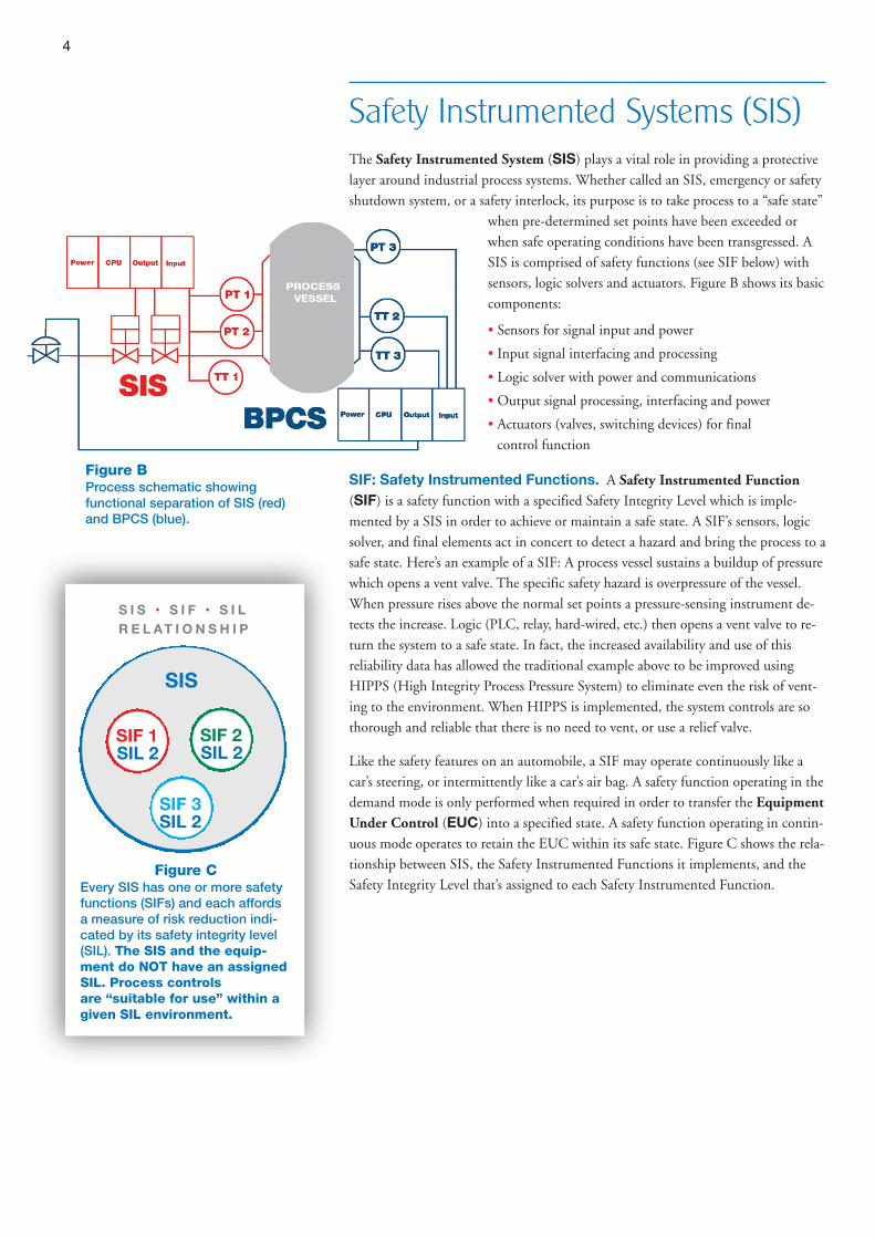
Safety Instrumented Systems (SIS)The Safety Instrumented System (SIS) plays a vital role in providing a protectivelayer around industrial process systems. Whether called an SIS, emergency or safetyshutdown system, or a safety interlock, its purpose is to take process to a “safe state”
when pre-determined set points have been exceeded orwhen safe operating conditions have been transgressed. A
SIS is comprised of safety functions (see SIF below) withsensors, logic solvers and actuators. Figure B shows its basiccomponents:
• Sensors for signal input and power
• Input signal interfacing and processing
• Logic solver with power and communications
• Output signal processing, interfacing and power
• Actuators (valves, switching devices) for finalcontrol function
SIF: Safety Instrumented Functions. A Safety Instrumented Function(SIF) is a safety function with a specified Safety Integrity Level which is imple-mented by a SIS in order to achieve or maintain a safe state. A SIF’s sensors, logicsolver, and final elements act in concert to detect a hazard and bring the process to asafe state. Here’s an example of a SIF: A process vessel sustains a buildup of pressurewhich opens a vent valve. The specific safety hazard is overpressure of the vessel.When pressure rises above the normal set points a pressure-sensing instrument de-tects the increase. Logic (PLC, relay, hard-wired, etc.) then opens a vent valve to re-turn the system to a safe state. In fact, the increased availability and use of thisreliability data has allowed the traditional example above to be improved usingHIPPS (High Integrity Process Pressure System) to eliminate even the risk of vent-ing to the environment. When HIPPS is implemented, the system controls are sothorough and reliable that there is no need to vent, or use a relief valve.
Like the safety features on an automobile, a SIF may operate continuously like acar’s steering, or intermittently like a car’s air bag. A safety function operating in thedemand mode is only performed when required in order to transfer the EquipmentUnder Control (EUC) into a specified state. A safety function operating in contin-uous mode operates to retain the EUC within its safe state. Figure C shows the rela-tionship between SIS, the Safety Instrumented Functions it implements, and theSafety Integrity Level that’s assigned to each Safety Instrumented Function.
SIL 2SIF 1
SIS
Figure CEvery SIS has one or more safetyfunctions (SIFs) and each affordsa measure of risk reduction indi-cated by its safety integrity level(SIL). The SIS and the equip-ment do NOT have an assignedSIL. Process controls are “suitable for use” within a given SIL environment.
SIL 2SIF 2
SIL 2SIF 3
S I S • S I F • S I L
R E L AT I O N S H I P
Figure BProcess schematic showingfunctional separation of SIS (red)and BPCS (blue).

5
Safety Life Cycle. Earlier we mentioned how a Hazard and Risk Assessmentstudy will determine the need for an SIS. This assessment is one part of a safety lifecycle which all major safety standards have specified. The safety life cycle shows asystematic approach for the development of a SIS. A simplified version is shown in
Figure D.
Safety Integrity Level (SIL) To what extent can a process be expected to perform safely? And, in the event of afailure, to what extent can the process be expected to fail safely? These questions areanswered through the assignment of a target Safety Integrity Level (SIL). SILs aremeasures of the safety risk of a given process.
IMPORTANT: It is incorrect to call a particular device “SIL 1” or “SIL 2.” For ex-ample, it is common to call the Eclipse 705 (51A) a “SIL 2 device.” This is inaccu-rate because the entire control loop must be taken into account. Technically, it isaccurate to say a device is “suitable for use within a given SIL environment.” For ex-ample, “the Eclipse 705 (51A) is suitable for use in a SIL 3 environment.”
Four Levels of Integrity. Historically, safety thinking categorized a process asbeing either safe or unsafe. For the new standards, however, safety isn’t considered abinary attribute; rather, it is stratified into four discrete levels of safety. Each levelrepresents an order of magnitude of risk reduction. The higher the SIL level, thegreater the impact of a failure and the lower the failure rate that is acceptable.
Safety Integrity Level is a way to indicate the tolerable failure rate of a particularsafety function. Standards require the assignment of a target SIL for any new orretrofitted SIF within the SIS. The assignment of the target SIL is a decision requir-ing the extension of the Hazards Analysis. The SIL assignment is based on theamount of risk reduction that is necessary to maintain the risk at an acceptablelevel. All of the SIS design, operation and maintenance choices must then be veri-fied against the target SIL. This ensures that the SIS can mitigate the assignedprocess risk.
Hardware Fault Tolerance. IEC61508-4 defines "fault tolerance" as the "abil-ity of a functional unit to continue to perform a required function in the presenceof faults or errors." Therefore, hardware fault tolerance is the ability of the hard-ware (complete hardware and software of the transmitter) to continue to performa required function in the presence of faults or errors. A hardware fault toleranceof 0 means that if there is one fault, the transmitter will not be able to performits function (measure level). A hardware fault tolerance of N means that N+1faults could cause a loss of the safety function. When someone does an FMEDAon a device, the resultant SFF has an associated hardware fault tolerance of 0.
Figure DThe Safety Life Cycle is a sequentialapproach to developing a Safety In-strumented System (SIS).References to a Safety Life Cycle canbe found in ANSI/ISA 84.00.01 Parts1–3; IEC 61508 Part 1; and IEC 61511Parts 1–3.
Type B(complex devices)
Table 3 from IEC-61508
Safe FailureFraction
Hardware Fault Tolerance
0 1 2
<60% Not SIL 1 SIL 2
60% to <90% SIL 1 SIL 2 SIL 3
90% to <99% SIL 2 SIL 3 SIL 4
≥99% SIL 3 SIL 4 SIL 4

6
Determining SIL Levels – Process When a Process Hazards Analysis(PHA) determines that a SIS is required, the level of risk reduction afforded by theSIS and the target SIL have to be assigned. The effectiveness of a SIS is described interms of “the probability it will fail to perform its required function when it iscalled upon to do so.” This is its Probability of Failure on Demand (PFD). Theaverage PFD (PFDavg) is used for SIL evaluation. Figure E shows the relationshipbetween PFDavg, availability of the safety system, risk reduction and the SIL levelvalues.
Various methodologies are used for assignment of target SILs. The determinationmust involve people with the relevant expertise and experience. Methodologies usedfor determining SILs include—but are not limited to—Simplified Calculations,Fault Tree Analysis, Layer of Protection Analysis (LOPA) and Markov Analysis.
Determining SIL Levels – Instrumentation
SIL levels for field instruments are established by one of two methods:
• FMEDA (Failures Modes, Effects and Diagnostic Analysis) is best when reviewedor certified by a third party like Exida or TUV although self-declarations can bedone by the manufacturer. A systematic analysis technique is necessary to deter-mine failure rates, failure modes and the diagnostic capability as defined by IEC61508/651511.
• Proven In Use (also called Prior Use) is typically used by a customer with a ma-ture instrument in known processes. This approach requires sufficient productoperational hours, revision history, fault reporting systems and field failure datato determine if there is evidence of systematic design faults in a product. IEC61508 provides levels of operational history required for each SIL. It is generallyconsidered of more value when done by users in their facility when comparinglike data. It is considered less reliable when done by a device manufacturer whosedata may be less relevant to the end user’s application.
SIL Availability PFDavg Risk Reduction Qualitative Consequence
4 >99.99% 10-5 to <10-4 100,000 to 10,000 Potential for fatalities in the community
3 99.9% 10-4 to <10-3 10,000 to 1,000 Potential for multiple on-site fatalities
2 99 to 99.9% 10-3 to <10-2 1,000 to 100 Potential for major on-site injuries or a fatality
1 90 to 99% 10-2 to <10-1 100 to 10 Potential for minor on-site injuries
SIL: Safety Integrity Level.
AVAILABILITY: The probability that equipment will perform itstask.
PFDavg: The average PFD used in calculating safety systemreliability. (PFD: Probability of Failure on Demand is theprobability of a system failing to respond to a demand for ac-tion arising from a potentially hazardous condition.)
* Both IEC and ANSI/ISA standards utilize similar tables cover-ing the same range of PFD values. ANSI/ISA, however, does not show a SIL 4. No standard process con-trols have yet been defined and tested for SIL 4.
Figure E SIL and Related Measures*
9.00E-03
8.00E-03
7.00E-03
6.00E-03
5.00E-03
4.00E-03
3.00E-03
2.00E-03
1.00E-03
0.00E+000 1 2 3 4 5 6 7 8 9 10
Years
PFDAVG(t) Eclipse Enhanced Model 705
Pro
bab
ility
705-510*-*
**
705-51A*-***

7
If you are using Manufacturer’s prior use data because a selected product does notreach the required level under FMEDA analysis, be aware that there are significantrequirements on the end user. A mature product must generally be used to have
the required field experience, and the design and assembly must be “frozen intime” in such a way that no upgrades, modifications or even configurationchanges may be allowed that may render the “Proven In Use” data useless.
A key result of the analyses is establishing a Safe Failure Fraction (SFF) for a prod-uct. Figure F below shows the relationship of SFF values, SIL ratings and the effectsof redundancy.
While two SIL 1 devices can be used together to achieve SIL 2 and twoSIL 2 devices to achieve SIL 3 (as suggested by the chart above), it is not automatic.Using redundancy to attain a higher SIL rating has additional requirements beyondhardware. It has an additional requirement of systematic safety which includes soft-ware integrity.
It is important to note that the most conservative approach to redundancy is to usedissimilar technologies. This reduces failures due to application issues.
Within the SFF determination is an understanding of types of failures and the abil-ity of the instrument to diagnose them. Figure G shows the basic relationship.
It should be obvious that the most critical category of failures is called DangerousUndetected (DU). For example, the Eclipse 705 (51A) has a SFF of 91.9 % with130 Dangerous Undetected failures; this means that 91.9 % of all failures are de-tected or safe (nuisance). Conversely, 130 represents the remaining 8.1 % that aredangerous and undetected (see Pages 10 & 11). The lower the number of Danger-ous undetected failures the better. This number is key in reliability evaluation evenfor non safety related applications.
Safe Failure Fraction (SFF)(for Type B, microprocessor-based devices)
NoRedundancy
SingleRedundancy
DoubleRedundancy
<60% Not Allowed SIL 1 SIL 2
60%<90% (typical competitor) SIL 1 SIL 2 SIL 3
90%<99% (Eclipse, Jupiter, E3) SIL 2 SIL 3 SIL 4
>99% SIL 3 SIL 4 SIL 4
Figure F
Detected Undetected
Safe Nuisance Nuisance
Dangerous
Importantbut acceptedsince they aredetected
Figure G Failure Designation
8
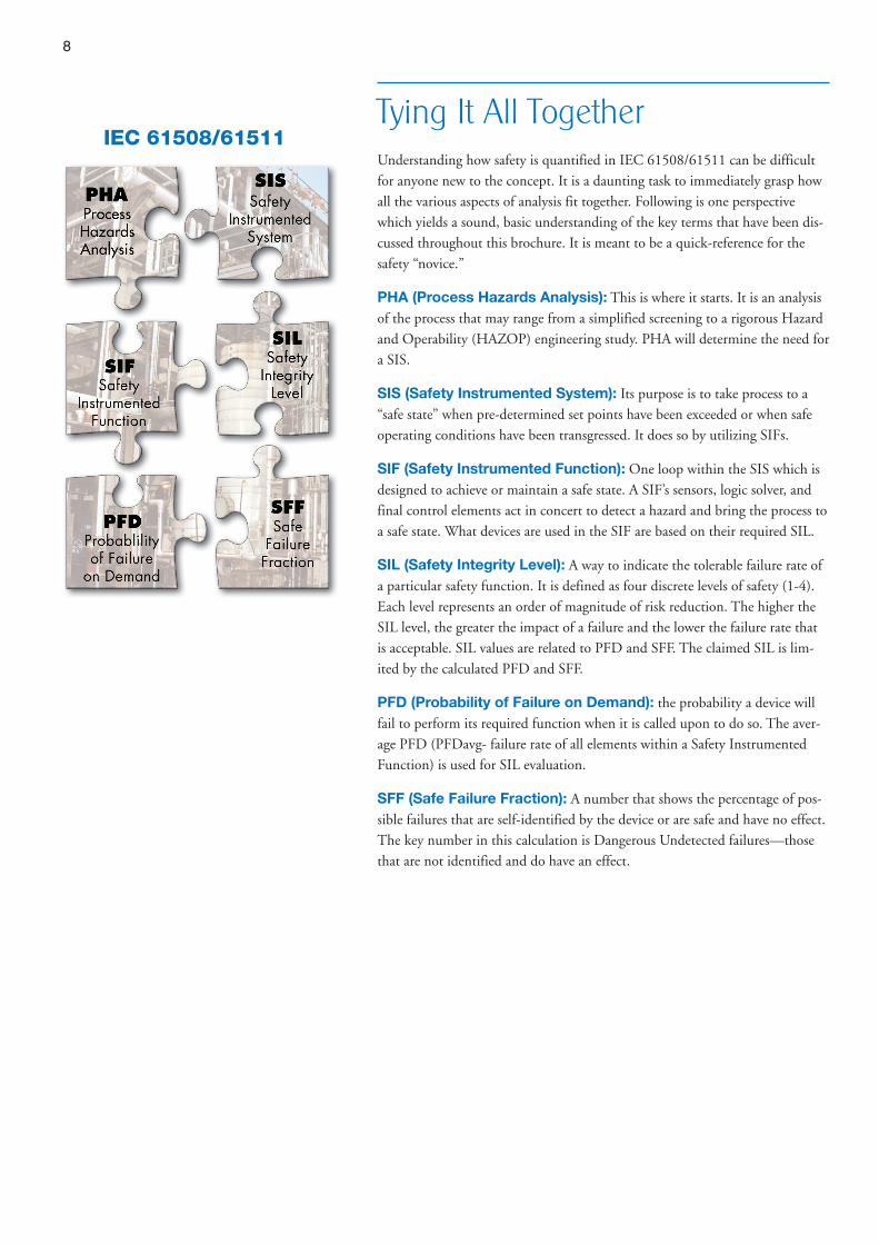
Tying It All TogetherUnderstanding how safety is quantified in IEC 61508/61511 can be difficultfor anyone new to the concept. It is a daunting task to immediately grasp howall the various aspects of analysis fit together. Following is one perspectivewhich yields a sound, basic understanding of the key terms that have been dis-cussed throughout this brochure. It is meant to be a quick-reference for the
safety “novice.”
PHA (Process Hazards Analysis): This is where it starts. It is an analysisof the process that may range from a simplified screening to a rigorous Hazardand Operability (HAZOP) engineering study. PHA will determine the need fora SIS.
SIS (Safety Instrumented System): Its purpose is to take process to a“safe state” when pre-determined set points have been exceeded or when safeoperating conditions have been transgressed. It does so by utilizing SIFs.
SIF (Safety Instrumented Function): One loop within the SIS which isdesigned to achieve or maintain a safe state. A SIF’s sensors, logic solver, andfinal control elements act in concert to detect a hazard and bring the process toa safe state. What devices are used in the SIF are based on their required SIL.
SIL (Safety Integrity Level): A way to indicate the tolerable failure rate ofa particular safety function. It is defined as four discrete levels of safety (1-4).Each level represents an order of magnitude of risk reduction. The higher theSIL level, the greater the impact of a failure and the lower the failure rate thatis acceptable. SIL values are related to PFD and SFF. The claimed SIL is lim-ited by the calculated PFD and SFF.
PFD (Probability of Failure on Demand): the probability a device willfail to perform its required function when it is called upon to do so. The aver-age PFD (PFDavg- failure rate of all elements within a Safety Instrumented
Function) is used for SIL evaluation.
SFF (Safe Failure Fraction): A number that shows the percentage of pos-sible failures that are self-identified by the device or are safe and have no effect.The key number in this calculation is Dangerous Undetected failures—thosethat are not identified and do have an effect.
IEC 61508/61511
9
FMEDA Device DataAssessing SIL-Suitable Controls A Failure Modes, Effects and DiagnosticAnalysis (FMEDA) is a detailed performance evaluation that estimates the failurerates, failure modes, and diagnostic capability of a device. The following pages showdata for specific devices.
The following explanations of key FMEDA data for SIL-suitable Magnetrol con-trols can be used as reference:
• FAIL DANGEROUS DETECTED (ldd) Dangerous failures detected by inter-nal diagnostics or a connected logic solver.
• FAIL DANGEROUS UNDETECTED (ldu) Dangerous failures that are not de-tected by the device.
• FAIL SAFE (lsd & lsu) Safe Failures (detected & undetected) that cause sys-tem to enter the fail-safe state without a demand from the process.
• FITS Failures in Time (FITs) where 1 FIT = 1 x 10⁻⁹ failures per hour. A sec-ond failure rate column has been added showing Annual data as it is also a com-monly used value.
• INSTRUMENT TYPE Type “A” units are devices without a complex micro-processor on board, and all possible failures on each component can be de-fined. Type “B” units have a microprocessor on board and the failure mode of acomponent is not well defined.
• MTBF Mean Time Between Failure is calculated from FMEDA data usingthe formula:
(ldd + ldu + lsd + lsu) * (10*E-9) * 8760• SERIES The brand and model designation of the control (e.g., Eclipse® 706).
• SFF Safe Failure Fraction is a percentage of Safe failures as compared to allfailures: SFF = 1 - ldu / ltotal
A SFF of 93 % for the Eclipse 706-51A, for example, means that 93 % of thepossible failures are self-identified by the device or are safe and have no effect.
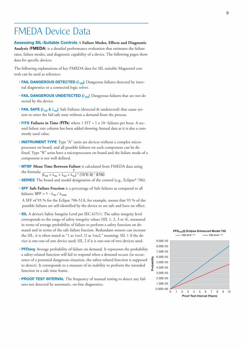
• SIL A device’s Safety Integrity Level per IEC 61511. The safety integrity levelcorresponds to the range of safety integrity values (SIL 1, 2, 3 or 4), measuredin terms of average probability of failure to perform a safety function on de-mand and in terms of the safe failure fraction. Redundant sensors can increasethe SIL, it is often stated as “1 as 1oo1 /2 as 1oo2,” meaning: SIL 1 if the de-vice is one-out-of-one device used; SIL 2 if it is one-out-of-two devices used.
• PFDavg Average probability of failure on demand. It represents the probabilitya safety-related function will fail to respond when a demand occurs (in occur-rence of a potential dangerous situation, the safety-related function is supposedto detect). It corresponds to a measure of its inability to perform the intendedfunction in a safe time frame.
• PROOF TEST INTERVAL The frequency of manual testing to detect any fail-ures not detected by automatic, on-line diagnostics.
9.00E-03
8.00E-03
7.00E-03
6.00E-03
5.00E-03
4.00E-03
3.00E-03
2.00E-03
1.00E-03
0.00E+000
705-510*-*** 705-51A*-***
1 2 3 4 5 6 7 8 9 10
Pro
bab
ility
Proof Test Interval (Years)
PFDAVG(t) Eclipse Enhanced Model 705
1
10
SIL-Suitable
Controls
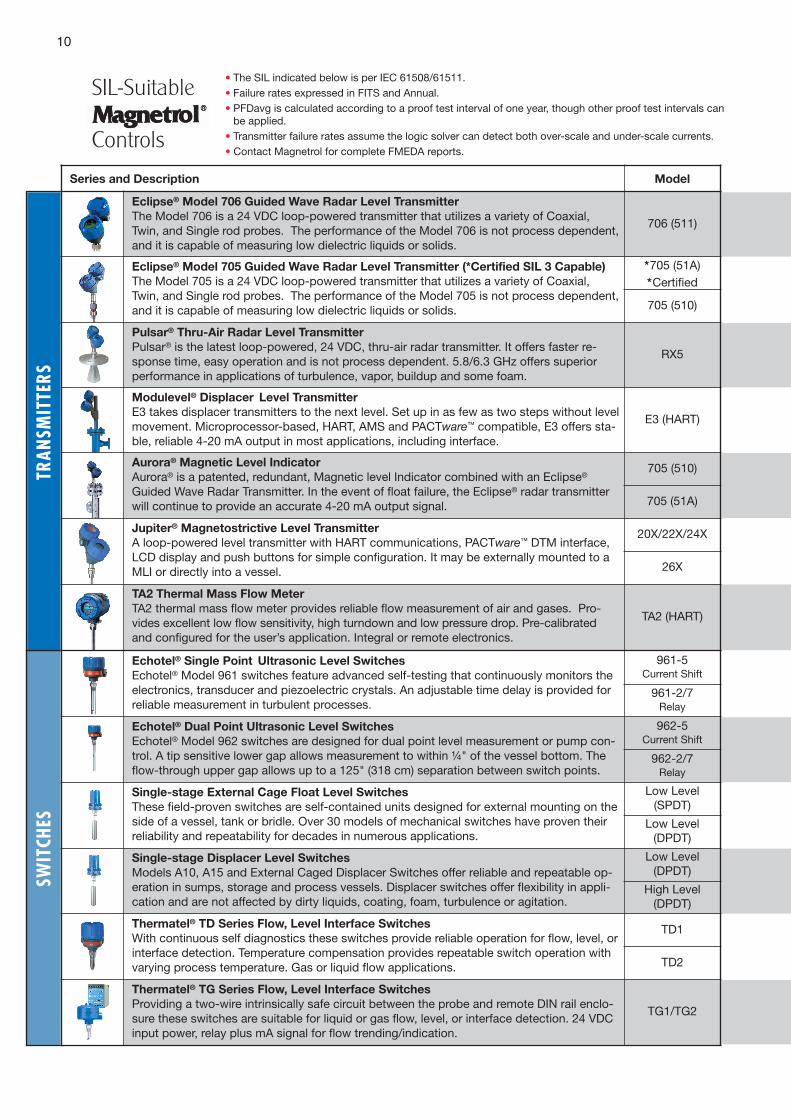
• The SIL indicated below is per IEC 61508/61511.• Failure rates expressed in FITS and Annual.• PFDavg is calculated according to a proof test interval of one year, though other proof test intervals canbe applied.
• Transmitter failure rates assume the logic solver can detect both over-scale and under-scale currents.• Contact Magnetrol for complete FMEDA reports.
SWIT
CHES
Series and Description Model
Eclipse® Model 706 Guided Wave Radar Level Transmitter
The Model 706 is a 24 VDC loop-powered transmitter that utilizes a variety of Coaxial,Twin, and Single rod probes. The performance of the Model 706 is not process dependent,and it is capable of measuring low dielectric liquids or solids.
706 (511)
Eclipse® Model 705 Guided Wave Radar Level Transmitter (*Certified SIL 3 Capable)
The Model 705 is a 24 VDC loop-powered transmitter that utilizes a variety of Coaxial,Twin, and Single rod probes. The performance of the Model 705 is not process dependent,and it is capable of measuring low dielectric liquids or solids.
*705 (51A)*Certified
705 (510)
Pulsar® Thru-Air Radar Level Transmitter
Pulsar® is the latest loop-powered, 24 VDC, thru-air radar transmitter. It offers faster re-sponse time, easy operation and is not process dependent. 5.8/6.3 GHz offers superiorperformance in applications of turbulence, vapor, buildup and some foam.
RX5
Modulevel® Displacer Level Transmitter
E3 takes displacer transmitters to the next level. Set up in as few as two steps without levelmovement. Microprocessor-based, HART, AMS and PACTware™ compatible, E3 offers sta-ble, reliable 4-20 mA output in most applications, including interface.
E3 (HART)
Aurora® Magnetic Level Indicator
Aurora® is a patented, redundant, Magnetic level Indicator combined with an Eclipse®
Guided Wave Radar Transmitter. In the event of float failure, the Eclipse® radar transmitterwill continue to provide an accurate 4-20 mA output signal.
705 (510)
705 (51A)
Jupiter® Magnetostrictive Level Transmitter
A loop-powered level transmitter with HART communications, PACTware™ DTM interface,LCD display and push buttons for simple configuration. It may be externally mounted to aMLI or directly into a vessel.
20X/22X/24X
26X
TA2 Thermal Mass Flow Meter
TA2 thermal mass flow meter provides reliable flow measurement of air and gases. Pro-vides excellent low flow sensitivity, high turndown and low pressure drop. Pre-calibratedand configured for the user’s application. Integral or remote electronics.
TA2 (HART)
Echotel® Single Point Ultrasonic Level Switches
Echotel® Model 961 switches feature advanced self-testing that continuously monitors theelectronics, transducer and piezoelectric crystals. An adjustable time delay is provided forreliable measurement in turbulent processes.
961-5Current Shift
961-2/7Relay
Echotel® Dual Point Ultrasonic Level Switches
Echotel® Model 962 switches are designed for dual point level measurement or pump con-trol. A tip sensitive lower gap allows measurement to within ¼" of the vessel bottom. Theflow-through upper gap allows up to a 125" (318 cm) separation between switch points.
962-5Current Shift
962-2/7Relay
Single-stage External Cage Float Level Switches
These field-proven switches are self-contained units designed for external mounting on theside of a vessel, tank or bridle. Over 30 models of mechanical switches have proven theirreliability and repeatability for decades in numerous applications.
Low Level(SPDT)
Low Level(DPDT)
Single-stage Displacer Level Switches
Models A10, A15 and External Caged Displacer Switches offer reliable and repeatable op-eration in sumps, storage and process vessels. Displacer switches offer flexibility in appli-cation and are not affected by dirty liquids, coating, foam, turbulence or agitation.
Low Level(DPDT)
High Level(DPDT)
Thermatel® TD Series Flow, Level Interface Switches
With continuous self diagnostics these switches provide reliable operation for flow, level, orinterface detection. Temperature compensation provides repeatable switch operation withvarying process temperature. Gas or liquid flow applications.
TD1
TD2
Thermatel® TG Series Flow, Level Interface Switches
Providing a two-wire intrinsically safe circuit between the probe and remote DIN rail enclo-sure these switches are suitable for liquid or gas flow, level, or interface detection. 24 VDCinput power, relay plus mA signal for flow trending/indication.
TG1/TG2
TRAN
SMIT
TERS

11
SIL
(1oo1)
Instrument
TypeSFF PFDavg
Fail DangerousUndetected
Fail DangerousDetected
Fail SafeAll
FITs ANNUAL FITs ANNUAL FITS ANNUAL
2 B 93% 6.67E-04 61 5.34E-04 728 6.37E-03 492 4.30E-03
2 B 92.7% 9.72E-04 51 4.46E-04 861 7.54E-03 578 5.06E-03
1 B 84.5% 8.06E-04 183 1.60E-03 567 4.97E-03 431 3.78E-03
1 B 73.7% 9.72E-04 222 1.94 E-03 308 2.70 E-03 314 2.75E-03
2 B 92.3% 2.95E-04 59 5.17 E-04 540 4.73 E-03 170 1.49E-03
1 B 84.5% 8.06E-04 183 1.60E-03 567 4.97E-03 431 3.78E-03
2 B 91.0% 4.69E-04 106 9.29E-04 650 5.69E-03 424 3.71E-03
1 B 83.7% 9.60E-04 218 1.91E-03 698 6.11E-03 421 3.69E-03
2 B 90.7% 5.45E-04 123 1.08E-03 793 6.95E-03 413 3.62E-03
1 B 88.4% 1.06E-03 218 1.91E-03 865 7.58E-03 800 7.01E-03
2 B 91.4% 1.61E-04 36 3.15E-04 288 2.52E-03 96 8.41E-04
2 B 92.0% 1.77E-04 40 3.50E-04 351 3.07E-03 106 9.29E-04
2 B 91.8% 1.87E-04 42 3.68E-04 362 3.17E-03 110 9.64E-04
2 B 91.5% 2.31E-04 52 4.56E-04 427 3.74E-03 130 1.14E-03
2 A 76.1% 4.82E-05 11 9.64E-05 0 0.00E+00 35 3.07E-04
2 A 82.6% 3.50E-05 8 7.01E-05 0 0.00E+00 38 3.33E-04
2 A 68.2% 1.76E-04 40 3.50E-04 71 6.22E-04 15 1.31E-04
2 A 77.7% 1.23E-04 28 2.45E-04 98 8.58E-04 0 000E-00
1 B 69.3% 6.13E-04 140 1.23E-03 252 2.21E-03 65 4.69E-04
1 B 73.0% 7.05E-04 161 1.41E-03 390 3.42E-03 46 4.03E-04
1 B 79.4% 5.04E-04 115 1.01E-03 188 165E-03 255 2.23E-03

CORPORATE HEADQUARTERS705 Enterprise Street • Aurora, Illinois 60504-8149 USA
Phone: 630-969-4000 • Fax: 630-969-9489magnetrol.com • [email protected]
EUROPEAN HEADQUARTERSHeikensstraat 6 • 9240 Zele, Belgium
Phone: +32 (0)52 45.11.11 • Fax: +32 (0)52 45.09.93
BRAZIL: Av. Dr. Mauro Lindemberg Monteiro, 185, Quadrante 16 • CEP 06278-010 • Osasco • São Paulo
CANADA: 145 Jardin Drive, Units 1 & 2 • Concord, Ontario L4K 1X7
CHINA: Plant 6, No. 191, Huajin Road • Minhang District • Shanghai 201108
DEUTSCHLAND: Alte Ziegelei 2–4 • D-51491 Overath
DUBAI: DAFZA Office 5EA 722, P.O. Box 293671 • Dubai, United Arab Emirates
INDIA: C-20 Community Centre • Janakpuri, New Delhi 110 058
ITALIA: Via Arese, 12 • 20159 Milano
RUSSIA: 198095, Saint-Petersburg • Marshala Govorova Street, House 35, Office 427
SINGAPORE: 33 Ubi Avenue 3 • #05-10 Vertex • Singapore 408868
UNITED KINGDOM: Regent Business Centre • Jubilee Road • Burgess Hill, West Sussex RH15 9TL
Magnetrol & Magnetrol logotype, Echotel, Eclipse, Modulevel, Pulsar, Thermatel, Aurora and Jupiter are trademarks of Magnetrol International, Incorporated.
PACTware™ is trademark of PACTware Consortium.
Copyright © 2015 Magnetrol International, Incorporated. All rights reserved. Printed in the USA.Bulletin: BE41-299.1 • Effective: March 2015
Visit magnetrol.com for more information on SIL-suitable Magnetrol controls including complete FMEDAreports. For further information regarding SIS, SIL and general process safety we recommend these onlineresources:
Subject: www:
IEC standards & bookstore ...........................................................................iec.ch/home
ISA standards & bookstore ...........................................................................isa.org
Exida engineering guides..............................................................................exida.com
TUV functional safety services......................................................................tuv-global.com
UK Health & Safety Executive.......................................................................hse.gov.uk
Institution of Chemical Engineers .................................................................icheme.org
IHS/Global engineering documents ..............................................................global.ihs.com
Factory Mutual process safety......................................................................fm global.com
OSHA process safety standards...................................................................osha.gov
Center for Chemical Process Safety.............................................................aiche.org
S p e c i a l A p p l i c at i o n S e r i e s