understanding implicit p25 control channel functions · understanding advanced p25 control channel...
TRANSCRIPT
For the very latest specifications visit www.aeroflex.com
ApplicationNote
Understanding Advanced P25 Control
Channel Functions
This application note deals with an advanced form of
P25 trunking using explicit messaging.1
Explicit messaging is currently used in the VHF and UHF
frequency bands and it is a feature that allows trunked
P25 networks to fully exploit the flexibility that the VHF
and UHF bands offer. As a precursor, we want to
review some of the basic terminology regarding P25
networks, especially the difference between implicit and
explicit modes of operation.
Implicit operation means that the radio's own internal
programming in conjunction with the P25 network mes-
sages will determine what channel/frequency pair the
radio assigns to a particular network channel. This is
also known as the "Short Channel form". The explicit
mode of operation assigns the actual channel/frequen-
cy over the air by providing the exact TX and RX fre-
quency assignments directly to the radio.
Note: Before reading this application note, it is highly recommended thatthe reader review the companion application note "Understanding 800MHz and VHF/UHF Implicit P25 Control Channel Functions using the2975". This will remove the need to review the basics of trunked radiooperation and provide the reader with an understanding of control channel functions and the P25 implicit mode of operation.
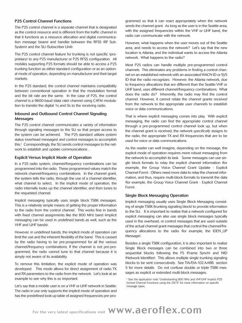
Typically, the implicit mode of operation uses a technique called
single block messaging, where explicit typically uses multi-block
messaging to convey trunking messages. However, certain single
and multi-block messages can be used on either type of network.
Review of Key Terminology
In any wireless mobile communication system, acronyms abound.
P25 is no different and there are certain acronyms and terms
used that the reader needs to know before using the 2975 for
testing P25 radio systems. The following is a list of the most com-
mon acronyms:
ARQ Automatic Retry Request
CAI Common Air Interface
CRC Cyclic Redundancy Check
EIA Electronic Industries Alliance
EXPLICIT The means in which the SU and FNE utilize
messaging to channel assignments using
advanced control channel messaging
techniques
FNE Fixed Network Equipment
GROUP ID A collection of users assigned a particular ID
number to designate them as a unique
category of users
ID Identifier
IMPLICIT The means in which the SU and FNE utilize
messaging to access pre-programmed chan-
nel parameters to establish channel assign-
ments
INTERCONNECT A call made to or from the Public Switched
Telephone Network
ISP Inbound Signaling Packet
ISM Inbound System Message - occurs from the
mobile to the NTS
LB Last Block Flag - indicates if this block is last or
more are to follow
LC Link Control Word
LCF Link Control Format
LCO Link Control Opcode
LDU1 Logical Link Data Unit 1
LRA Location Registration Area
LSB Least Significant Bit
MBT Multiple Block Trunking
MFID ManuFacturer's Identity
MI Message Indicator
MOBILE For this application note, a mobile denotes
either a portable or mobile.
ms Millisecond
MSB Most Significant Bit
NARROW BAND 12.5 kHz bandwidth operation
TX Transmit
Octet 8 bits of information used in messaging
Opcode Identifies the message type
OSP Outbound Signaling Packet
P Protected Flag
PARAMETRICS The RF performance of a radio system includ-
ing RF Error, Power and Modulation Accuracy,
as well as radio sensitivity
PROTOCOL A series of communication processes defined
to set up calls and to send various forms of
data to and from the mobile.
PSTN Public Switched Telephone Network
REGISTRATION The initial handshake process that allows the
radio to communicate
RFSS RF Sub-System
RX Receive
SCCB Secondary Control Channel Broadcast
SS Status Symbols
SU Subscriber Unit - the mobile or portable radio
SYS ID System Identifier
TIA Telecommunications Industry Association
TILE This applies to the 2975. A tile is window view
of various functions within the 2975. There are
two tiles. One is a 1/4 tile and the other is 1/8
tile. The 1/4 tiles are used for displaying
repeater simulators, minimized spectrum
analyzers and oscilloscopes, and take up 1/4
of the total screen area. 1/8 tiles are used for
meters and take up 1/8 of the total screen
area.
TSBK Trunking Signaling BlocK
WACN ID Wide Area Communication Network Identifier
For the very latest specifications visit www.aeroflex.com
P25 Control Channel Functions
The P25 control channel is a separate channel that is designated
as the control resource and is different from the traffic channel in
that it functions as a resource allocation and digital communica-
tion message bearer and handler between the RFSS (RF Sub-
System) and the SU (Subscriber Unit).
The P25 control channel feature for trunking is not specific (pro-
prietary) to any P25 manufacturer or P25 RFSS configuration. All
mobiles supporting P25 formats should be able to access a P25
trunking function as either standard configuration or as an option-
al mode of operation, depending on manufacturer and their target
markets.
In the P25 standard, the control channel maintains compatibility
between conventional operation in that the modulation format
and the bit rate are the same. In the case of P25, the control
channel is a 9600-baud (data rate) channel using C4FM modula-
tion to transfer the digital 1s and 0s to the receiving radio.
Inbound and Outbound Control Channel Signaling
Messages
The P25 control channel communicates a variety of information
through signaling messages to the SU so that proper access to
the system can be achieved. The P25 standard utilizes system
status (overhead messages) and control messages to accomplish
this.2 Correspondingly, the SU sends control messages to the net-
work to establish and update communications .
Explicit Versus Implicit Mode of Operation
In a P25 radio system, channel/frequency combinations can be
programmed into the radio. These programmed values match the
network channel/frequency combinations. In the channel grant,
the system tells the radio, through the use of a channel identifier,
what channel to select. In the implicit mode of operation, the
radio internally looks up the channel identifier, and then tunes to
the requested channel.
Implicit messaging typically uses single block TSBK messages.
This is a relatively simple means of getting the proper information
to the radio from the control channel. This works fine in bands
with fixed channel assignments like the 800 MHz band (implicit
messaging can be used in undefined bands as well, such as the
VHF and UHF bands).
However, in undefined bands, the implicit mode of operation can
limit the use and the inherent flexibility of the band. This is caused
by the radio having to be pre-programmed for all the various
channel/frequency combinations. If the channel is not pre-pro-
grammed, the radio cannot tune to that channel because it is
simply not aware of its availability.
To remove this limitation, the explicit mode of operation was
developed. This mode allows for direct assignment of radio TX
and RX parameters to the radio from the network. Let's look at an
example to see why this is so important.
Let's say that a mobile user is on a VHF or UHF network in Seattle.
The radio in use only supports the implicit mode of operation and
has the predefined look-up table of assigned frequencies pre-pro-
grammed so that it can react appropriately when the network
sends the channel grant. As long as the user is in the Seattle area,
with the assigned frequencies within the VHF or UHF band, the
radio can communicate with the network.
However, what happens when the user moves out of the Seattle
area, and needs to access the network? Let's say that the new
location is Atlanta, and the individual wants to access the Atlanta
network. What happens to the radio?
Most P25 radios can handle multiple pre-programmed control
channels. This eliminates any problems in finding a control chan-
nel on an established network with an associated WACN ID or SYS
ID that the radio recognizes. However, the Atlanta network, due
to frequency allocations that are different than the Seattle VHF or
UHF band, uses different channel/frequency combinations. What
does the radio do? Inherently, the radio may find the control
channel. However, it cannot relate the channel grants received
from the network to the appropriate user channels to establish
voice or data communications.
That is where explicit messaging comes into play. With explicit
messaging, the radio can find the appropriate control channel
through a pre-programmed control channel look up, but when
the channel grant is received, the network specifically assigns to
the radio, the appropriate TX and RX frequencies that are to be
used for voice or data communications.
As the reader can well imagine, depending on the message, the
explicit mode of operation requires more robust messaging from
the network to accomplish its task. Some messages can use sin-
gle block formats to relay the explicit channel information (for
example, the Group Voice Channel Grant Update - Explicit
Channel Form). Others need more data to relay the channel infor-
mation, and thus, require multi-block formats to transmit the data
(for example, the Group Voice Channel Grant - Explicit Channel
Form).
Single Block Messaging Operation
Implicit messaging usually uses Single Block Messaging consist-
ing of single TSBK (trunking signaling block) to provide information
to the SU. It is important to realize that a network configured for
explicit messaging can also use single block messages typically
used in the overhead, or control messages that are used outside
of the actual channel grant messages that control the channel/fre-
quency allocations to the radio (for example, the IDEN_UP
Message).
Besides a single TSBK configuration, it is also important to realize
Single Block messages can be combined into two or three
sequential blocks following the FS (Frame Synch) and NID
(Network Identifier). This allows multiple single trunking signaling
blocks to be sent consecutively. See TIA/EIA-102.AABB section
5 for more details. Do not confuse double or triple TSBK mes-
sages as explicit or extended multi-block messages.
2 See the application note "Understanding 800 MHz and VHF/UHF Implicit P25Control Channel Functions using the 2975" for more information on specific message types.
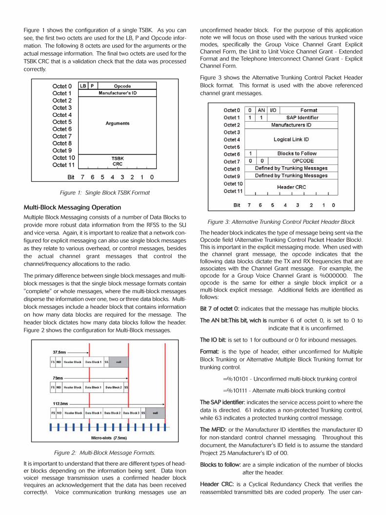
Figure 1 shows the configuration of a single TSBK. As you can
see, the first two octets are used for the LB, P and Opcode infor-
mation. The following 8 octets are used for the arguments or the
actual message information. The final two octets are used for the
TSBK CRC that is a validation check that the data was processed
correctly.
Figure 1: Single Block TSBK Format
Multi-Block Messaging Operation
Multiple Block Messaging consists of a number of Data Blocks to
provide more robust data information from the RFSS to the SU
and vice versa. Again, it is important to realize that a network con-
figured for explicit messaging can also use single block messages
as they relate to various overhead, or control messages, besides
the actual channel grant messages that control the
channel/frequency allocations to the radio.
The primary difference between single block messages and multi-
block messages is that the single block message formats contain
"complete" or whole messages, where the multi-block messages
disperse the information overone, two or three data blocks. Multi-
block messages include a header block that contains information
on how many data blocks are required for the message. The
header block dictates how many data blocks follow the header.
Figure 2 shows the configuration for Multi-Block messages.
Figure 2: Multi-Block Message Formats.
It is important to understand that there are different types of head-
er blocks depending on the information being sent. Data (non
voice) message transmission uses a confirmed header block
(requires an acknowledgement that the data has been received
correctly). Voice communication trunking messages use an
unconfirmed header block. For the purpose of this application
note we will focus on those used with the various trunked voice
modes, specifically the Group Voice Channel Grant Explicit
Channel Form, the Unit to Unit Voice Channel Grant - Extended
Format and the Telephone Interconnect Channel Grant - Explicit
Channel Form.
Figure 3 shows the Alternative Trunking Control Packet Header
Block format. This format is used with the above referenced
channel grant messages.
Figure 3: Alternative Trunking Control Packet Header Block
The headerblock indicates the type of message being sent via the
Opcode field (Alternative Trunking Control Packet Header Block).
This is important in the explicit messaging mode. When used with
the channel grant message, the opcode indicates that the
following data blocks dictate the TX and RX frequencies that are
associates with the Channel Grant message. For example, the
opcode for a Group Voice Channel Grant is %000000. The
opcode is the same for either a single block implicit or a
multi-block explicit message. Additional fields are identified as
follows:
BBiitt 77 ooff oocctteett 00:: indicates that the message has multiple blocks.
TThhee AANN bbiitt::TThhiiss bbiitt,, wwiicchh iiss number 6 of octet 0, is set to 0 to
indicate that it is unconfirmed.
TThhee IIOO bbiitt:: is set to 1 for outbound or 0 for inbound messages.
FFoorrmmaatt:: is the type of header, either unconfirmed for Multiple
Block Trunking or Alternative Multiple Block Trunking format for
trunking control.
=%10101 - Unconfirmed multi-block trunking control
=%10111 - Alternate multi-block trunking control
TThhee SSAAPP iiddeennttiiffiieerr:: indicates the service access point to where the
data is directed. 61 indicates a non-protected Trunking control,
while 63 indicates a protected trunking control message.
TThhee MMFFIIDD:: or the Manufacturer ID identifies the manufacturer ID
for non-standard control channel messaging. Throughout this
document, the Manufacturer's ID field is to assume the standard
Project 25 Manufacturer's ID of 00.
BBlloocckkss ttoo ffoollllooww:: are a simple indication of the number of blocks
after the header.
HHeeaaddeerr CCRRCC:: is a Cyclical Redundancy Check that verifies the
reassembled transmitted bits are coded properly. The user can-
For the very latest specifications visit www.aeroflex.com
not set this field.
Octet 8 and 9 are defined by the type of message being sent.
This is covered later in this application note.
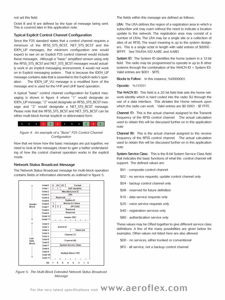
Typical Explicit Control Channel Configuration
Since the P25 standard states that a control channel requires a
minimum of the RFSS_STS_BCST, NET_STS_BCST and the
IDEN_UP messages, the minimum configuration one would
expect to see on an Explicit P25 control channel would include
these messages. Although a "basic" simplified version using only
the RFSS_STS_BCST and NET_STS_BCST messages would actual-
ly work in an implicit messaging environment, it would not work
on in Explicit messaging system . That is because the IDEN_UP
message contains data that is essential to the Explicit radio's oper-
ation. The IDEN_UP_VU message is a modified form of the
message and is used for the VHF and UHF band operation.
A typical "basic" control channel configuration for Explicit mes-
saging is shown in figure 4 where "1" would designate an
IDEN_UP message, "2" would designate an RFSS_STS_BCST mes-
sage and "3" would designate a NET_STS_BCST message.
Please note that the RFSS_STS_BCST and NET_STS_BCST can be
either multi-block format (explicit) or abbreviated form.
Figure 4: An example of a "Basic" P25 Control Channel
Configuration
Now that we know how the basic messages are put together, we
need to look at the messages closer to gain a better understand-
ing of how the control channel operation works in the explicit
mode.
Network Status Broadcast Message
The Network Status Broadcast message for multi-block operation
contains fields or information elements as outlined in figure 5.
Figure 5: The Multi-Block Extended Network Status Broadcast
Message
The fields within this message are defined as follows:
LLRRAA:: The LRA defines the region of a registration area in which a
subscriber unit may roam without the need to indicate a location
update to the network. The registration area may consist of a
number of LRAs. The LRA may be a single site or a collection of
sites of an RFSS. The exact meaning is up to the system design-
ers. This is a single octet in length with valid entries of $0000 -
$FFFF. See TIA/EIA-102 AABC and AABD.
SSyysstteemm IIDD:: The System ID identifies the home system in a 12-bit
field. The radio may be programmed to operate in up to 8 other
systems through the combination of the (WACN ID + System ID).
Valid entries are $001 - $FFE.
BBlloocckkss ttoo FFoollllooww:: In this instance, %0000001.
OOppccooddee:: %111011
TThhee WWAACCNN IIDD:: This field is a 20 bit field that sets the home net-
work identity which is hard coded into the radio SU through the
use of a data interface. This dictates the Home network upon
which the radio can work. Valid entries are $0 0001 - $F FFFE.
CChhaannnneell ((TT)):: This is the actual channel assigned to the Transmit
frequency of the RFSS control channel. The actual calculation
used to obtain this will be discussed further on in this application
note
CChhaannnneell ((RR)):: This is the actual channel assigned to the receive
frequency of the RFSS control channel. The actual calculation
used to obtain this will be discussed further on in this application
note
SSyysstteemm SSeerrvviiccee CCllaassss:: This is the 8-bit System Service Class field
that indicates the basic functions of what the control channel will
support. The defined values are:
$01 - composite control channel
$02 - no service requests; update control channel only
$04 - backup control channel only
$08 - reserved for future definition
$10 - data service requests only
$20 - voice service requests only
$40 - registration services only
$80 - authentication service only
These values may be ORed together to give different service class
definitions. A few of the many possibilities are given below for
examples. Other values not listed here are also allowed.
$00 - no services, either trunked or conventional
$F0 - all service, not a backup control channel
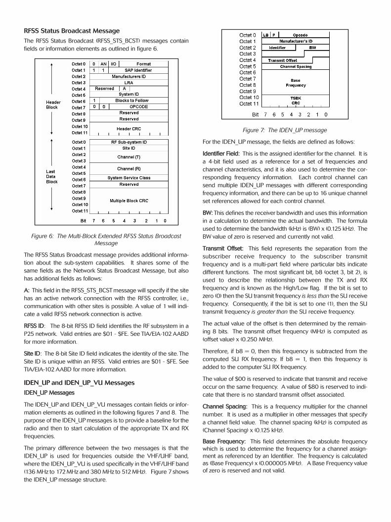
RFSS Status Broadcast Message
The RFSS Status Broadcast (RFSS_STS_BCST) messages contain
fields or information elements as outlined in figure 6.
Figure 6: The Multi-Block Extended RFSS Status Broadcast
Message
The RFSS Status Broadcast message provides additional informa-
tion about the sub-system capabilities. It shares some of the
same fields as the Network Status Broadcast Message, but also
has additional fields as follows:
AA:: This field in the RFSS_STS_BCST message will specify if the site
has an active network connection with the RFSS controller, i.e.,
communication with other sites is possible. A value of 1 will indi-
cate a valid RFSS network connection is active.
RRFFSSSS IIDD: The 8-bit RFSS ID field identifies the RF subsystem in a
P25 network. Valid entries are $01 - $FE. See TIA/EIA-102 AABD
for more information.
SSiittee IIDD: The 8-bit Site ID field indicates the identity of the site. The
Site ID is unique within an RFSS. Valid entries are $01 - $FE. See
TIA/EIA-102 AABD for more information.
IDEN_UP and IDEN_UP_VU Messages
IIDDEENN__UUPP MMeessssaaggeess
The IDEN_UP and IDEN_UP_VU messages contain fields or infor-
mation elements as outlined in the following figures 7 and 8. The
purpose of the IDEN_UP messages is to provide a baseline for the
radio and then to start calculation of the appropriate TX and RX
frequencies.
The primary difference between the two messages is that the
IDEN_UP is used for frequencies outside the VHF/UHF band,
where the IDEN_UP_VU is used specifically in the VHF/UHF band
(136 MHz to 172 MHz and 380 MHz to 512 MHz). Figure 7 shows
the IDEN_UP message structure.
Figure 7: The IDEN_UP message
For the IDEN_UP message, the fields are defined as follows:
IIddeennttiiffiieerr FFiieelldd:: This is the assigned identifier for the channel. It is
a 4-bit field used as a reference for a set of frequencies and
channel characteristics, and it is also used to determine the cor-
responding frequency information. Each control channel can
send multiple IDEN_UP messages with different corresponding
frequency information, and there can be up to 16 unique channel
set references allowed for each control channel.
BBWW:: This defines the receiver bandwidth and uses this information
in a calculation to determine the actual bandwidth. The formula
used to determine the bandwidth (kHz) is (BW) x (0.125 kHz). The
BW value of zero is reserved and currently not valid.
TTrraannssmmiitt OOffffsseett:: This field represents the separation from the
subscriber receive frequency to the subscriber transmit
frequency and is a multi-part field where particular bits indicate
different functions. The most significant bit, b8 (octet 3, bit 2), is
used to describe the relationship between the TX and RX
frequency and is known as the High/Low flag. If the bit is set to
zero (0) then the SU transmit frequency is less than the SU receive
frequency. Consequently, if the bit is set to one (1), then the SU
transmit frequency is greater than the SU receive frequency.
The actual value of the offset is then determined by the remain-
ing 8 bits. The transmit offset frequency (MHz) is computed as
(offset value) x (0.250 MHz).
Therefore, if b8 = 0, then this frequency is subtracted from the
computed SU RX frequency. If b8 = 1, then this frequency is
added to the computer SU RX frequency.
The value of $00 is reserved to indicate that transmit and receive
occur on the same frequency. A value of $80 is reserved to indi-
cate that there is no standard transmit offset associated.
CChhaannnneell SSppaacciinngg:: This is a frequency multiplier for the channel
number. It is used as a multiplier in other messages that specify
a channel field value. The channel spacing (kHz) is computed as
(Channel Spacing) x (0.125 kHz).
BBaassee FFrreeqquueennccyy:: This field determines the absolute frequency
which is used to determine the frequency for a channel assign-
ment as referenced by an Identifier. The frequency is calculated
as (Base Frequency) x (0.000005 MHz). A Base Frequency value
of zero is reserved and not valid.
For the very latest specifications visit www.aeroflex.com
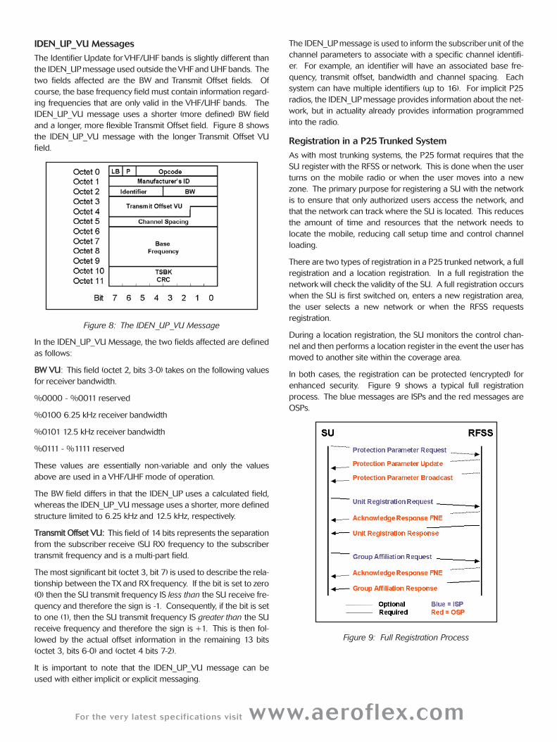
IDEN_UP_VU Messages
The Identifier Update forVHF/UHF bands is slightly different than
the IDEN_UP message used outside the VHF and UHF bands. The
two fields affected are the BW and Transmit Offset fields. Of
course, the base frequency field must contain information regard-
ing frequencies that are only valid in the VHF/UHF bands. The
IDEN_UP_VU message uses a shorter (more defined) BW field
and a longer, more flexible Transmit Offset field. Figure 8 shows
the IDEN_UP_VU message with the longer Transmit Offset VU
field.
Figure 8: The IDEN_UP_VU Message
In the IDEN_UP_VU Message, the two fields affected are defined
as follows:
BBWW VVUU: This field (octet 2, bits 3-0) takes on the following values
for receiver bandwidth.
%0000 - %0011 reserved
%0100 6.25 kHz receiver bandwidth
%0101 12.5 kHz receiver bandwidth
%0111 - %1111 reserved
These values are essentially non-variable and only the values
above are used in a VHF/UHF mode of operation.
The BW field differs in that the IDEN_UP uses a calculated field,
whereas the IDEN_UP_VU message uses a shorter, more defined
structure limited to 6.25 kHz and 12.5 kHz, respectively.
TTrraannssmmiitt OOffffsseett VVUU:: This field of 14 bits represents the separation
from the subscriber receive (SU RX) frequency to the subscriber
transmit frequency and is a multi-part field.
The most significant bit (octet 3, bit 7) is used to describe the rela-
tionship between the TX and RX frequency. If the bit is set to zero
(0) then the SU transmit frequency IS less than the SU receive fre-
quency and therefore the sign is -1. Consequently, if the bit is set
to one (1), then the SU transmit frequency IS greater than the SU
receive frequency and therefore the sign is +1. This is then fol-
lowed by the actual offset information in the remaining 13 bits
(octet 3, bits 6-0) and (octet 4 bits 7-2).
It is important to note that the IDEN_UP_VU message can be
used with either implicit or explicit messaging.
The IDEN_UP message is used to inform the subscriber unit of the
channel parameters to associate with a specific channel identifi-
er. For example, an identifier will have an associated base fre-
quency, transmit offset, bandwidth and channel spacing. Each
system can have multiple identifiers (up to 16). For implicit P25
radios, the IDEN_UP message provides information about the net-
work, but in actuality already provides information programmed
into the radio.
Registration in a P25 Trunked System
As with most trunking systems, the P25 format requires that the
SU register with the RFSS or network. This is done when the user
turns on the mobile radio or when the user moves into a new
zone. The primary purpose for registering a SU with the network
is to ensure that only authorized users access the network, and
that the network can track where the SU is located. This reduces
the amount of time and resources that the network needs to
locate the mobile, reducing call setup time and control channel
loading.
There are two types of registration in a P25 trunked network, a full
registration and a location registration. In a full registration the
network will check the validity of the SU. A full registration occurs
when the SU is first switched on, enters a new registration area,
the user selects a new network or when the RFSS requests
registration.
During a location registration, the SU monitors the control chan-
nel and then performs a location register in the event the user has
moved to another site within the coverage area.
In both cases, the registration can be protected (encrypted) for
enhanced security. Figure 9 shows a typical full registration
process. The blue messages are ISPs and the red messages are
OSPs.
Figure 9: Full Registration Process
Unit Registration Request and Group Affiliation
Request (SU Originated ISP)
If we look at the registration process, the basic implementation
requires a registration message and an affiliation message. The
first is the Unit Registration Request (U_REG_REQ). This is from
the mobile to the RFSS and uses a single TSBK format. The
detailed Unit Registration Request message from the radio is
shown in figure 10.
Figure 10: Unit Registration Request (Originated from the
Mobile Radio)
All the definitions noted earlier for the network status broadcast
and RFSS status broadcast messages OSPs apply. In addition,
however, there is a new field, not previously defined, called
Source ID.
SSoouurrccee IIDD:: A 24-bit unit identity portion of the unique sub-
scriber unit identity. This field along with the WACN ID and
System ID uniquely addresses a subscriber unit. This can also
be called the Unit ID.
Note that the subscriber unit has the appropriate WACN ID that is
echoed back to the network for verification that the SU accepted
the Wide Area Communication Network code. This message uti-
lizes the Last Block flag identifier field, the encryption P-Bit and the
appropriate Opcode that identifies this message as a Unit
Registration Request. The System ID is preprogrammed into the
SU as is the Source ID (UID). Manufacturer ID is also shown,
which for a P25 system is 00.
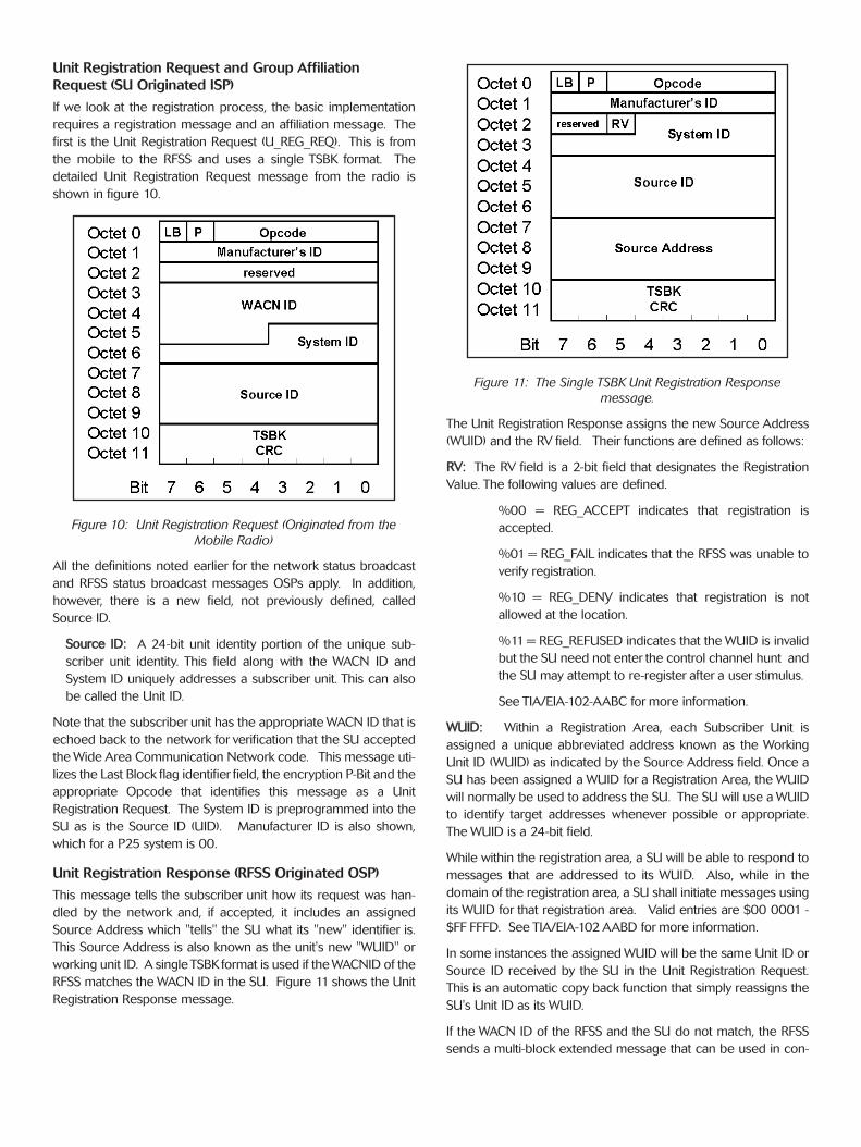
Unit Registration Response (RFSS Originated OSP)
This message tells the subscriber unit how its request was han-
dled by the network and, if accepted, it includes an assigned
Source Address which "tells" the SU what its "new" identifier is.
This Source Address is also known as the unit's new "WUID" or
working unit ID. A single TSBK format is used if the WACNID of the
RFSS matches the WACN ID in the SU. Figure 11 shows the Unit
Registration Response message.
Figure 11: The Single TSBK Unit Registration Response
message.
The Unit Registration Response assigns the new Source Address
(WUID) and the RV field. Their functions are defined as follows:
RRVV:: The RV field is a 2-bit field that designates the Registration
Value. The following values are defined.
%00 = REG_ACCEPT indicates that registration is
accepted.
%01 = REG_FAIL indicates that the RFSS was unable to
verify registration.
%10 = REG_DENY indicates that registration is not
allowed at the location.
%11 = REG_REFUSED indicates that the WUID is invalid
but the SU need not enter the control channel hunt and
the SU may attempt to re-register after a user stimulus.
See TIA/EIA-102-AABC for more information.
WWUUIIDD:: Within a Registration Area, each Subscriber Unit is
assigned a unique abbreviated address known as the Working
Unit ID (WUID) as indicated by the Source Address field. Once a
SU has been assigned a WUID for a Registration Area, the WUID
will normally be used to address the SU. The SU will use a WUID
to identify target addresses whenever possible or appropriate.
The WUID is a 24-bit field.
While within the registration area, a SU will be able to respond to
messages that are addressed to its WUID. Also, while in the
domain of the registration area, a SU shall initiate messages using
its WUID for that registration area. Valid entries are $00 0001 -
$FF FFFD. See TIA/EIA-102 AABD for more information.
In some instances the assigned WUID will be the same Unit ID or
Source ID received by the SU in the Unit Registration Request.
This is an automatic copy back function that simply reassigns the
SU's Unit ID as its WUID.
If the WACN ID of the RFSS and the SU do not match, the RFSS
sends a multi-block extended message that can be used in con-
For the very latest specifications visit www.aeroflex.com
junction with the Roaming Address Command
(ROAM_ADDR_CMD) from the RFSS to establish a new WACN
into the SU's Roaming Address Stack. This would be contingent
upon the network establishing the validity of the SU to allow roam-
ing. For this application note, we will assume a valid WACN ID is
found. See TIA/EIA-102.AABC and AABD for more details.
Group Affiliation Request (SU Originated ISP)
After a registration request, the SU will send a Group Affiliation
Request (GRP_AFF_REQ). The detailed Group Affiliation Request
message is shown in figure 12
Figure 12: Group Affiliation Request (Originated from the
Mobile Radio)
The message contains some of the fields that the Unit
Registration Request contains, except that the WACN ID is
removed and the Group ID field is added. This message can be
invoked by the RFSS at any time by broadcasting the Group ID
Query command. The Group ID is pre-programmed into the SU.
GGrroouupp IIDD:: This defines the 16-bit group identifier that together
with the WACN ID and System ID uniquely defines a group.
Again, if the WACN ID of the RFSS and the SU do not match, the
SU sends a multi-block extended message that includes the SU's
WACN ID. For this application note, we will assume a valid WACN
ID is found. See TIA/EIA-102.AABC and AABD for more details.
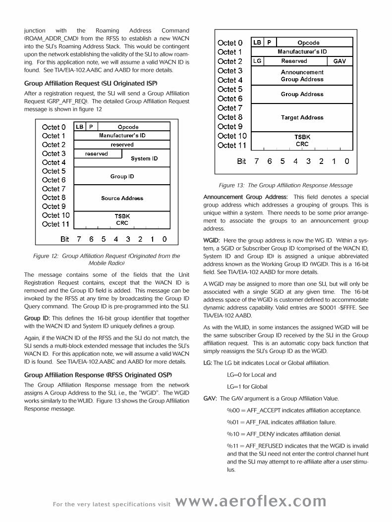
Group Affiliation Response (RFSS Originated OSP)
The Group Affiliation Response message from the network
assigns A Group Address to the SU, i.e., the "WGID". The WGID
works similarly to the WUID. Figure 13 shows the Group Affiliation
Response message.
Figure 13: The Group Affiliation Response Message
AAnnnnoouunncceemmeenntt GGrroouupp AAddddrreessss:: This field denotes a special
group address which addresses a grouping of groups. This is
unique within a system. There needs to be some prior arrange-
ment to associate the groups to an announcement group
address.
WWGGIIDD:: Here the group address is now the WG ID. Within a sys-
tem, a SGID or Subscriber Group ID (comprised of the WACN ID,
System ID and Group ID) is assigned a unique abbreviated
address known as the Working Group ID (WGID). This is a 16-bit
field. See TIA/EIA-102 AABD for more details.
A WGID may be assigned to more than one SU, but will only be
associated with a single SGID at any given time. The 16-bit
address space of the WGID is customer defined to accommodate
dynamic address capability. Valid entries are $0001 -$FFFE. See
TIA/EIA-102 AABD.
As with the WUID, in some instances the assigned WGID will be
the same subscriber Group ID received by the SU in the Group
affiliation request. This is an automatic copy back function that
simply reassigns the SU's Group ID as the WGID.
LLGG:: The LG bit indicates Local or Global affiliation.
LG=0 for Local and
LG=1 for Global
GGAAVV:: The GAV argument is a Group Affiliation Value.
%00 = AFF_ACCEPT indicates affiliation acceptance.
%01 = AFF_FAIL indicates affiliation failure.
%10 = AFF_DENY indicates affiliation denial.
%11 = AFF_REFUSED indicates that the WGID is invalid
and that the SU need not enter the control channel hunt
and the SU may attempt to re-affiliate after a user stimu-
lus.
The abbreviated format is used if both the source and target SU
have the same HOME system designation, and the target unit
resides in the HOME system. If not, an extended Group Affiliation
Response is sent. For the purposes of this application note, we
will assume that the SU have the same HOME system designation
and that the target unit resides in the HOME system.
Understanding Group, Unit and PSTN Call Sequences
As the call is initiated and managed, additional messages are
involved in the call sequence. For example, Figure 14 shows the
required messages to establish a P25 unit to group voice call after
the Unit Registration and Group Affiliation process is complete.
Figure 14: Unit to Group Call Sequence Chart
Once the mobile is registered and has affiliated, the only com-
mands required to move the mobile to a particular channel, is to
issue a channel grant after a Group Voice Request from an SU.
The Unit to Unit channel grant is more detailed in that the
required communications from the Source SU through the RFSS
to the Destination SU requires the issuing of an answer request
from the RFSS and an answer response from the Destination SU.
Figure 15 shows the call sequence for a Unit to Unit call.
Figure 15: Unit to Unit Call Sequence Chart
The Unit to PSTN call requires interaction between the RFSS and
the PSTN. The P25 Air interface messages require a PSTN inter-
connect request, either using a dial request or a PSTN request.
The dial request includes actual digits dialed, and can be up to 10
digits - or more than 10 digits, using the extended or multi-block
messaging. The PSTN request is a user defined reference
associated with a dialing sequence. Figure 16 shows the Unit to
PSTN interconnect call process.
Figure 16: Unit to PSTN Call Sequence Chart
Establishing a Group Call in an Explicit P25 Trunked
System
As in any communication system, a user initiates a call. This call
can be defined as two types, either a SU originated call or a SU
terminated call. The difference is that the SU either generates
the call request or the SU receives a call request. Either action
ends up with a channel grant being delivered to the SU to begin
voice communications. In Figure 14 above, the group call
sequence begins with a Group Voice Request from the SU to the
RFSS. Let's look further at the messages involved in this
transaction.
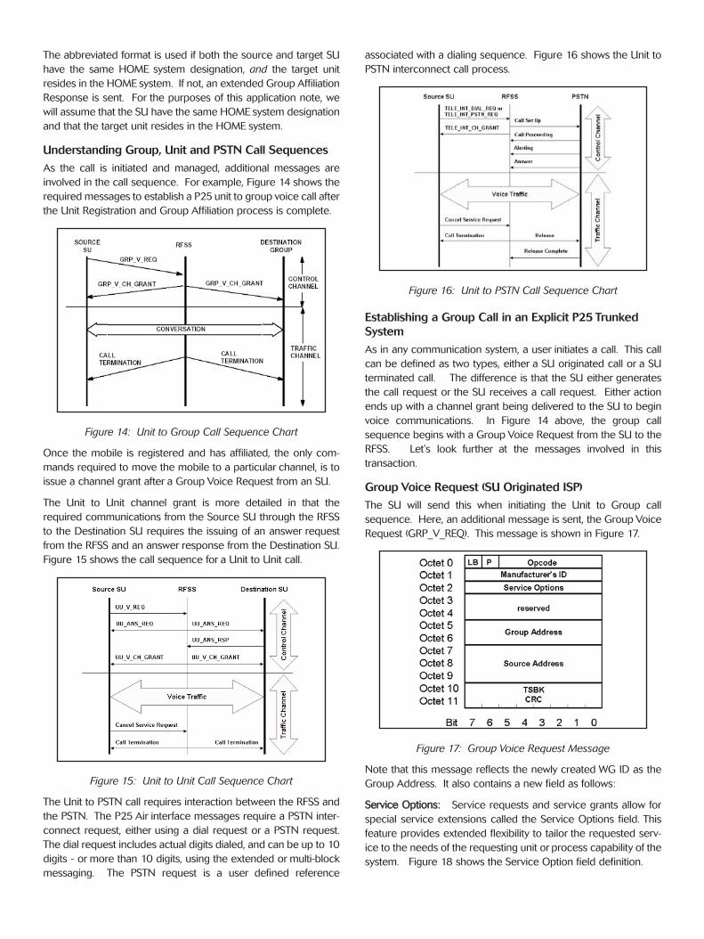
Group Voice Request (SU Originated ISP)
The SU will send this when initiating the Unit to Group call
sequence. Here, an additional message is sent, the Group Voice
Request (GRP_V_REQ). This message is shown in Figure 17.
Figure 17: Group Voice Request Message
Note that this message reflects the newly created WG ID as the
Group Address. It also contains a new field as follows:
SSeerrvviiccee OOppttiioonnss:: Service requests and service grants allow for
special service extensions called the Service Options field. This
feature provides extended flexibility to tailor the requested serv-
ice to the needs of the requesting unit or process capability of the
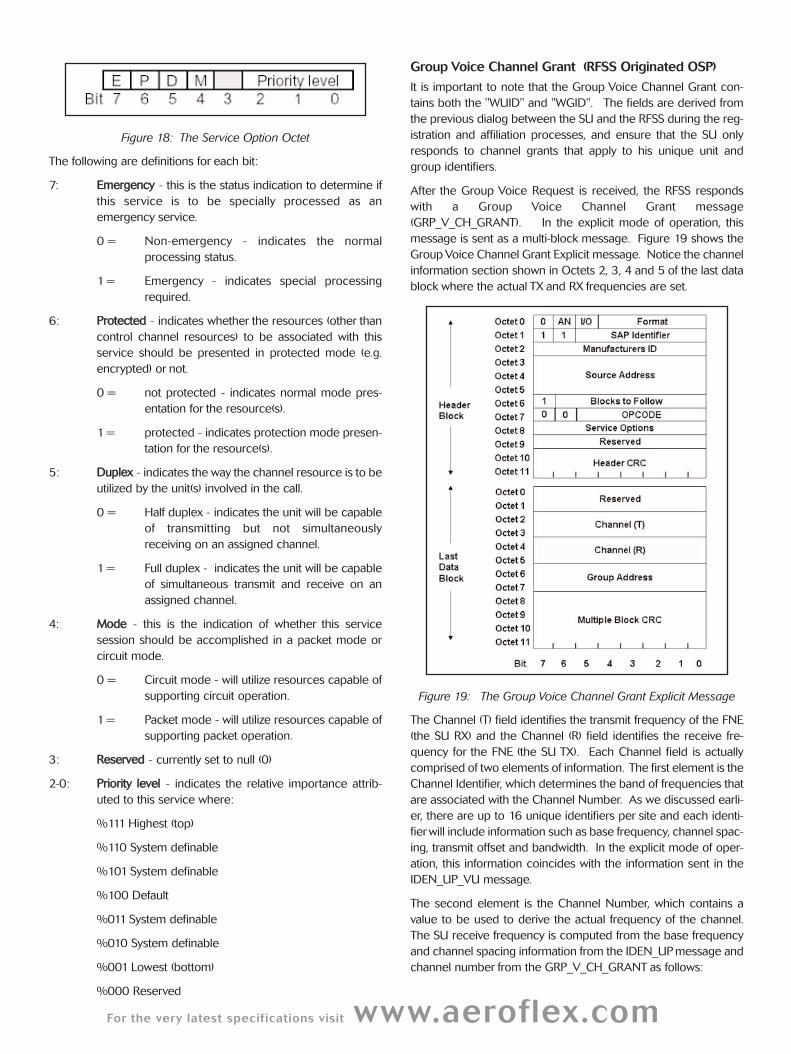
system. Figure 18 shows the Service Option field definition.
For the very latest specifications visit www.aeroflex.com
Figure 18: The Service Option Octet
The following are definitions for each bit:
7: EEmmeerrggeennccyy - this is the status indication to determine if
this service is to be specially processed as an
emergency service.
0 = Non-emergency - indicates the normal
processing status.
1 = Emergency - indicates special processing
required.
6: PPrrootteecctteedd - indicates whether the resources (other than
control channel resources) to be associated with this
service should be presented in protected mode (e.g.
encrypted) or not.
0 = not protected - indicates normal mode pres-
entation for the resource(s).
1 = protected - indicates protection mode presen-
tation for the resource(s).
5: DDuupplleexx - indicates the way the channel resource is to be
utilized by the unit(s) involved in the call.
0 = Half duplex - indicates the unit will be capable
of transmitting but not simultaneously
receiving on an assigned channel.
1 = Full duplex - indicates the unit will be capable
of simultaneous transmit and receive on an
assigned channel.
4: MMooddee - this is the indication of whether this service
session should be accomplished in a packet mode or
circuit mode.
0 = Circuit mode - will utilize resources capable of
supporting circuit operation.
1 = Packet mode - will utilize resources capable of
supporting packet operation.
3: RReesseerrvveedd - currently set to null (0)
2-0: PPrriioorriittyy lleevveell - indicates the relative importance attrib-
uted to this service where:
%111 Highest (top)
%110 System definable
%101 System definable
%100 Default
%011 System definable
%010 System definable
%001 Lowest (bottom)
%000 Reserved
Group Voice Channel Grant (RFSS Originated OSP)
It is important to note that the Group Voice Channel Grant con-
tains both the "WUID" and "WGID". The fields are derived from
the previous dialog between the SU and the RFSS during the reg-
istration and affiliation processes, and ensure that the SU only
responds to channel grants that apply to his unique unit and
group identifiers.
After the Group Voice Request is received, the RFSS responds
with a Group Voice Channel Grant message
(GRP_V_CH_GRANT). In the explicit mode of operation, this
message is sent as a multi-block message. Figure 19 shows the
Group Voice Channel Grant Explicit message. Notice the channel
information section shown in Octets 2, 3, 4 and 5 of the last data
block where the actual TX and RX frequencies are set.
Figure 19: The Group Voice Channel Grant Explicit Message
The Channel (T) field identifies the transmit frequency of the FNE
(the SU RX) and the Channel (R) field identifies the receive fre-
quency for the FNE (the SU TX). Each Channel field is actually
comprised of two elements of information. The first element is the
Channel Identifier, which determines the band of frequencies that
are associated with the Channel Number. As we discussed earli-
er, there are up to 16 unique identifiers per site and each identi-
fierwill include information such as base frequency, channel spac-
ing, transmit offset and bandwidth. In the explicit mode of oper-
ation, this information coincides with the information sent in the
IDEN_UP_VU message.
The second element is the Channel Number, which contains a
value to be used to derive the actual frequency of the channel.
The SU receive frequency is computed from the base frequency
and channel spacing information from the IDEN_UP message and
channel number from the GRP_V_CH_GRANT as follows:
SU RX = (Base Frequency) + (Channel Number) x (Channel
Spacing). Figure 20 shows the channel information broken into
its two elements.
Figure 20: The Channel Information
How Mobiles Calculate the RX and TX Frequencies
In the explicit mode of operation, the SU will use the channel
identifier information and the channel number in conjunction with
the IDEN_UP_VU message to calculate the SU RX and SU TX
frequencies.
Calculating the SU RX Frequency
The SU RX Frequency is calculated as follows:
SU RX = (Base Frequency) + (Channel Number) x (Channel
Spacing).
NNoottee:: Base Frequency is calculated as (Base Frequency) x
(0.000005 MHz) from the IDEN_UP_VU message. See TIA/EIA-
102 AABC-2 section 2.3.5.
We know that both the Base Frequency and the Channel Spacing
are derived from the IDEN_UP_VU message. The transmitted
Channel Number from the Group Voice Channel Grant Explicit
message becomes the key part of the equation for frequency
assignments.
Calculating the SU TX Frequency
The SU transmit base frequency is computed as follows:
Using the Transmit Offset VU field from the IDEN_UP_VU mes-
sage, the SU TX Frequency is simply: Sign (Transmit Offset x
Channel Spacing x 12500).
That value is then added to the SU RX frequency.
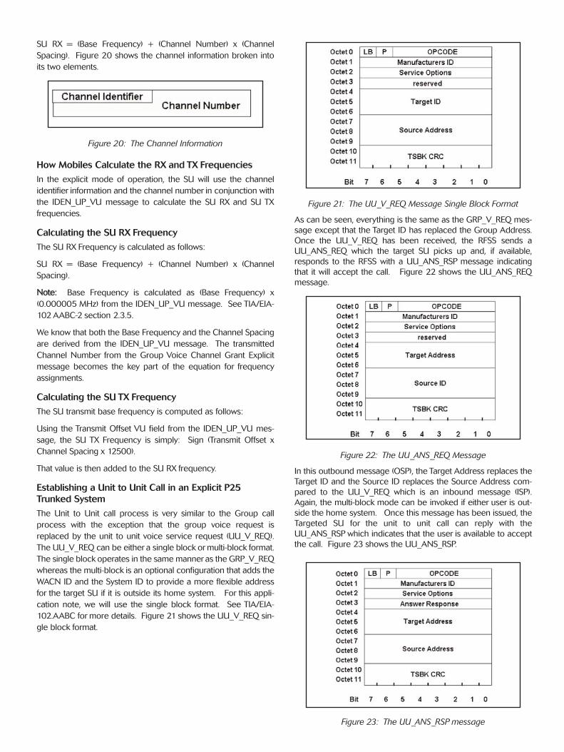
Establishing a Unit to Unit Call in an Explicit P25
Trunked System
The Unit to Unit call process is very similar to the Group call
process with the exception that the group voice request is
replaced by the unit to unit voice service request (UU_V_REQ).
The UU_V_REQ can be either a single block or multi-block format.
The single block operates in the same manner as the GRP_V_REQ
whereas the multi-block is an optional configuration that adds the
WACN ID and the System ID to provide a more flexible address
for the target SU if it is outside its home system. For this appli-
cation note, we will use the single block format. See TIA/EIA-
102.AABC for more details. Figure 21 shows the UU_V_REQ sin-
gle block format.
Figure 21: The UU_V_REQ Message Single Block Format
As can be seen, everything is the same as the GRP_V_REQ mes-
sage except that the Target ID has replaced the Group Address.
Once the UU_V_REQ has been received, the RFSS sends a
UU_ANS_REQ which the target SU picks up and, if available,
responds to the RFSS with a UU_ANS_RSP message indicating
that it will accept the call. Figure 22 shows the UU_ANS_REQ
message.
Figure 22: The UU_ANS_REQ Message
In this outbound message (OSP), the Target Address replaces the
Target ID and the Source ID replaces the Source Address com-
pared to the UU_V_REQ which is an inbound message (ISP).
Again, the multi-block mode can be invoked if either user is out-
side the home system. Once this message has been issued, the
Targeted SU for the unit to unit call can reply with the
UU_ANS_RSP which indicates that the user is available to accept
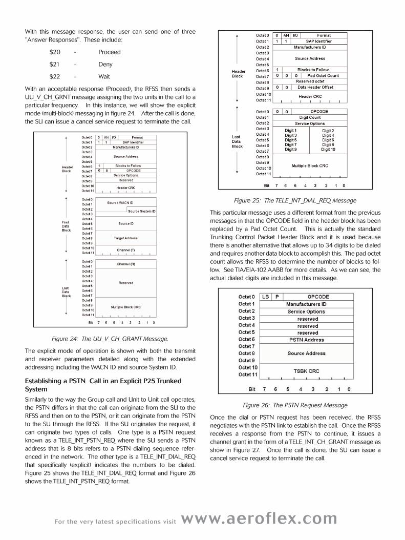
the call. Figure 23 shows the UU_ANS_RSP.
Figure 23: The UU_ANS_RSP message
For the very latest specifications visit www.aeroflex.com
With this message response, the user can send one of three
"Answer Responses". These include:
$20 - Proceed
$21 - Deny
$22 - Wait
With an acceptable response (Proceed), the RFSS then sends a
UU_V_CH_GRNT message assigning the two units in the call to a
particular frequency. In this instance, we will show the explicit
mode (multi-block) messaging in figure 24. After the call is done,
the SU can issue a cancel service request to terminate the call.
Figure 24: The UU_V_CH_GRANT Message.
The explicit mode of operation is shown with both the transmit
and receiver parameters detailed along with the extended
addressing including the WACN ID and source System ID.
Establishing a PSTN Call in an Explicit P25 Trunked
System
Similarly to the way the Group call and Unit to Unit call operates,
the PSTN differs in that the call can originate from the SU to the
RFSS and then on to the PSTN, or it can originate from the PSTN
to the SU through the RFSS. If the SU originates the request, it
can originate two types of calls. One type is a PSTN request
known as a TELE_INT_PSTN_REQ where the SU sends a PSTN
address that is 8 bits refers to a PSTN dialing sequence refer-
enced in the network. The other type is a TELE_INT_DIAL_REQ
that specifically (explicit) indicates the numbers to be dialed.
Figure 25 shows the TELE_INT_DIAL_REQ format and Figure 26
shows the TELE_INT_PSTN_REQ format.
Figure 25: The TELE_INT_DIAL_REQ Message
This particular message uses a different format from the previous
messages in that the OPCODE field in the header block has been
replaced by a Pad Octet Count. This is actually the standard
Trunking Control Packet Header Block and it is used because
there is another alternative that allows up to 34 digits to be dialed
and requires another data block to accomplish this. The pad octet
count allows the RFSS to determine the number of blocks to fol-
low. See TIA/EIA-102.AABB for more details. As we can see, the
actual dialed digits are included in this message.
Figure 26: The PSTN Request Message
Once the dial or PSTN request has been received, the RFSS
negotiates with the PSTN link to establish the call. Once the RFSS
receives a response from the PSTN to continue, it issues a
channel grant in the form of a TELE_INT_CH_GRANT message as
show in Figure 27. Once the call is done, the SU can issue a
cancel service request to terminate the call.
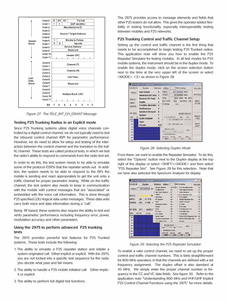
Figure 27: The TELE_INT_CH_GRANT Message
Testing P25 Trunking Radios in an Explicit mode
Since P25 Trunking systems utilize digital voice channels con-
trolled by a digital control channel, we do not typically need to test
the inbound control channel (ISP) for parametric performance.
However, we do need to allow for setup and testing of the inter-
action between the control channel and the transition to the traf-
fic channel. These tests are called protocol tests, in which we test
the radio's ability to respond to commands from the radio test set.
In order to do this, the test system needs to be able to emulate
some of the protocol (OSPs) that the repeater sends out. In addi-
tion, the system needs to be able to respond to the ISPs the
mobile is sending and react appropriately to get the unit onto a
traffic channel for proper parametric testing. While on the traffic
channel, the test system also needs to keep in communication
with the mobile with control messages that are "associated" or
embedded with the voice call information. This is done through
P25 specified LDU (logical data units) messages. These data units
carry both voice and data information during a "call".
Being RF based, these systems also require the ability to test and
verify parametric performance including frequency error, power,
modulation accuracy and other parameters.
Using the 2975 to perform advanced P25 trunking
tests
The 2975 provides powerful test features for P25 Trunked
systems. These tests include the following:
1. The ability to emulate a P25 repeater station and initiate a
system originated call. Either implicit or explicit. With the 2975,
you are not locked into a specific test sequence for the radio.
You decide what pass and fail means.
2. The ability to handle a P25 mobile initiated call. Either implic-
it or explicit.
3. The ability to perform full digital test functions.
The 2975 provides access to message elements and fields that
other P25 testers do not allow. This gives the operator added flex-
ibility in testing functionality, especially interoperability testing
between mobiles and P25 networks.
P25 Trunking Control and Traffic Channel Setup
Setting up the control and traffic channel is the first thing that
needs to be accomplished to begin testing P25 Trunked radios.
This application note will show you how to enable the P25
Repeater Simulator for testing mobiles. In all test modes for P25
mobile systems, the instrument should be in the duplex mode. To
enable the duplex mode, click on the screen selection button
next to the time at the very upper left of the screen or select
<MODE>, <3> as shown in Figure 28.
Figure 28: Selecting Duplex Mode
From there, we want to enable the Repeater Simulator. To do this,
select the "Options" button next to the Duplex display at the top
right of the display or select <SHIFT>,<MODE> and then select
"P25 Repeater Sim". See Figure 29 for this selection. Note that
we have also selected the Spectrum Analyzer for display.
Figure 29: Selecting the P25 Repeater Simulator
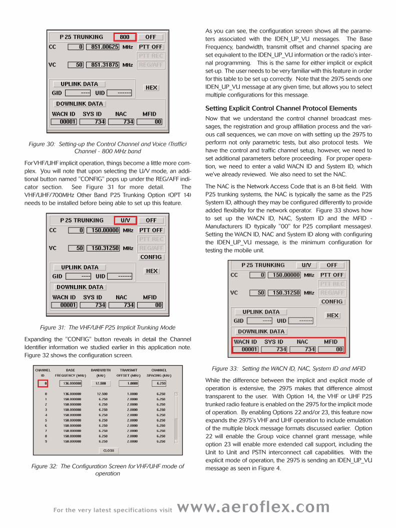
To enable a valid control channel, we need to set up the proper
control and traffic channel numbers. This is fairly straightforward
for 800 MHz operation, in that the channels are defined with a set
frequency assignment. The duplex offset is also standard at
45 MHz. We simply enter the proper channel number or fre-
quency in the CC and VC data fields. See figure 30. Refer to the
application note "Understanding 800 MHz and VHF/UHF Implicit
P25 Control Channel Functions using the 2975" for more details.
For the very latest specifications visit www.aeroflex.com
Figure 30: Setting-up the Control Channel and Voice (Traffic)
Channel - 800 MHz band
ForVHF/UHF implicit operation, things become a little more com-
plex. You will note that upon selecting the U/V mode, an addi-
tional button named "CONFIG" pops up under the REG/AFF indi-
cator section. See Figure 31 for more detail. The
VHF/UHF/700MHz Other Band P25 Trunking Option (OPT 14)
needs to be installed before being able to set up this feature.
Figure 31: The VHF/UHF P25 Implicit Trunking Mode
Expanding the "CONFIG" button reveals in detail the Channel
Identifier information we studied earlier in this application note.
Figure 32 shows the configuration screen.
Figure 32: The Configuration Screen for VHF/UHF mode of
operation
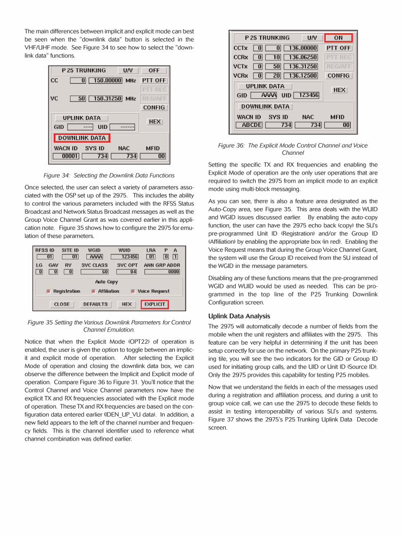
As you can see, the configuration screen shows all the parame-
ters associated with the IDEN_UP_VU messages. The Base
Frequency, bandwidth, transmit offset and channel spacing are
set equivalent to the IDEN_UP_VU information or the radio's inter-
nal programming. This is the same for either implicit or explicit
set-up. The userneeds to be very familiarwith this feature in order
for this table to be set up correctly. Note that the 2975 sends one
IDEN_UP_VU message at any given time, but allows you to select
multiple configurations for this message.
Setting Explicit Control Channel Protocol Elements
Now that we understand the control channel broadcast mes-
sages, the registration and group affiliation process and the vari-
ous call sequences, we can move on with setting up the 2975 to
perform not only parametric tests, but also protocol tests. We
have the control and traffic channel setup, however, we need to
set additional parameters before proceeding. For proper opera-
tion, we need to enter a valid WACN ID and System ID, which
we've already reviewed. We also need to set the NAC.
The NAC is the Network Access Code that is an 8-bit field. With
P25 trunking systems, the NAC is typically the same as the P25
System ID, although they may be configured differently to provide
added flexibility for the network operator. Figure 33 shows how
to set up the WACN ID, NAC, System ID and the MFID -
Manufacturers ID (typically "00" for P25 compliant messages).
Setting the WACN ID, NAC and System ID along with configuring
the IDEN_UP_VU message, is the minimum configuration for
testing the mobile unit.
Figure 33: Setting the WACN ID, NAC, System ID and MFID
While the difference between the implicit and explicit mode of
operation is extensive, the 2975 makes that difference almost
transparent to the user. With Option 14, the VHF or UHF P25
trunked radio feature is enabled on the 2975 for the implicit mode
of operation. By enabling Options 22 and/or 23, this feature now
expands the 2975's VHF and UHF operation to include emulation
of the multiple block message formats discussed earlier. Option
22 will enable the Group voice channel grant message, while
option 23 will enable more extended call support, including the
Unit to Unit and PSTN interconnect call capabilities. With the
explicit mode of operation, the 2975 is sending an IDEN_UP_VU
message as seen in Figure 4.
The main differences between implicit and explicit mode can best
be seen when the "downlink data" button is selected in the
VHF/UHF mode. See Figure 34 to see how to select the "down-
link data" functions.
Figure 34: Selecting the Downlink Data Functions
Once selected, the user can select a variety of parameters asso-
ciated with the OSP set up of the 2975. This includes the ability
to control the various parameters included with the RFSS Status
Broadcast and Network Status Broadcast messages as well as the
Group Voice Channel Grant as was covered earlier in this appli-
cation note. Figure 35 shows how to configure the 2975 foremu-
lation of these parameters.
Figure 35 Setting the Various Downlink Parameters for Control
Channel Emulation.
Notice that when the Explicit Mode (OPT22) of operation is
enabled, the user is given the option to toggle between an implic-
it and explicit mode of operation. After selecting the Explicit
Mode of operation and closing the downlink data box, we can
observe the difference between the Implicit and Explicit mode of
operation. Compare Figure 36 to Figure 31. You'll notice that the
Control Channel and Voice Channel parameters now have the
explicit TX and RX frequencies associated with the Explicit mode
of operation. These TX and RX frequencies are based on the con-
figuration data entered earlier (IDEN_UP_VU data). In addition, a
new field appears to the left of the channel number and frequen-
cy fields. This is the channel identifier used to reference what
channel combination was defined earlier.
Figure 36: The Explicit Mode Control Channel and Voice
Channel
Setting the specific TX and RX frequencies and enabling the
Explicit Mode of operation are the only user operations that are
required to switch the 2975 from an implicit mode to an explicit
mode using multi-block messaging.
As you can see, there is also a feature area designated as the
Auto-Copy area, see Figure 35. This area deals with the WUID
and WGID issues discussed earlier. By enabling the auto-copy
function, the user can have the 2975 echo back (copy) the SU's
pre-programmed Unit ID (Registration) and/or the Group ID
(Affiliation) by enabling the appropriate box (in red). Enabling the
Voice Request means that during the Group Voice Channel Grant,
the system will use the Group ID received from the SU instead of
the WGID in the message parameters.
Disabling any of these functions means that the pre-programmed
WGID and WUID would be used as needed. This can be pro-
grammed in the top line of the P25 Trunking Downlink
Configuration screen.
Uplink Data Analysis
The 2975 will automatically decode a number of fields from the
mobile when the unit registers and affiliates with the 2975. This
feature can be very helpful in determining if the unit has been
setup correctly for use on the network. On the primary P25 trunk-
ing tile, you will see the two indicators for the GID or Group ID
used for initiating group calls, and the UID or Unit ID (Source ID).
Only the 2975 provides this capability for testing P25 mobiles.
Now that we understand the fields in each of the messages used
during a registration and affiliation process, and during a unit to
group voice call, we can use the 2975 to decode these fields to
assist in testing interoperability of various SU's and systems.
Figure 37 shows the 2975's P25 Trunking Uplink Data Decode
screen.
For the very latest specifications visit www.aeroflex.com
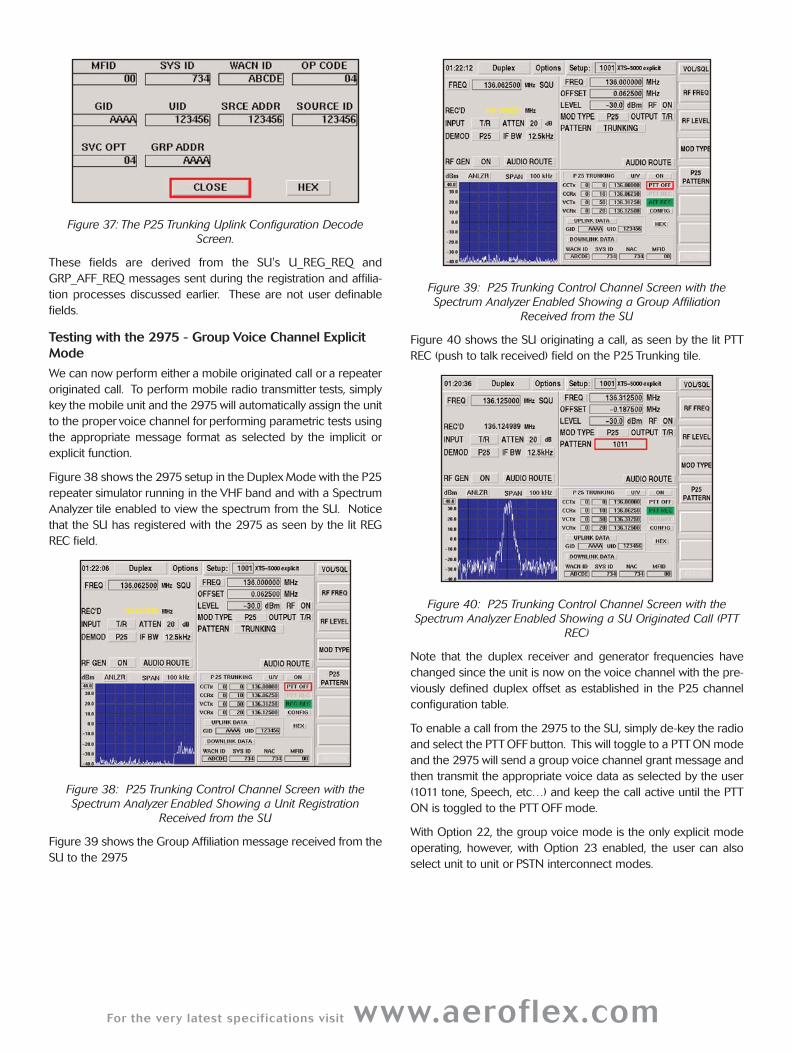
Figure 37: The P25 Trunking Uplink Configuration Decode
Screen.
These fields are derived from the SU's U_REG_REQ and
GRP_AFF_REQ messages sent during the registration and affilia-
tion processes discussed earlier. These are not user definable
fields.
Testing with the 2975 - Group Voice Channel Explicit
Mode
We can now perform either a mobile originated call or a repeater
originated call. To perform mobile radio transmitter tests, simply
key the mobile unit and the 2975 will automatically assign the unit
to the proper voice channel for performing parametric tests using
the appropriate message format as selected by the implicit or
explicit function.
Figure 38 shows the 2975 setup in the Duplex Mode with the P25
repeater simulator running in the VHF band and with a Spectrum
Analyzer tile enabled to view the spectrum from the SU. Notice
that the SU has registered with the 2975 as seen by the lit REG
REC field.
Figure 38: P25 Trunking Control Channel Screen with the
Spectrum Analyzer Enabled Showing a Unit Registration
Received from the SU
Figure 39 shows the Group Affiliation message received from the
SU to the 2975
Figure 39: P25 Trunking Control Channel Screen with the
Spectrum Analyzer Enabled Showing a Group Affiliation
Received from the SU
Figure 40 shows the SU originating a call, as seen by the lit PTT
REC (push to talk received) field on the P25 Trunking tile.
Figure 40: P25 Trunking Control Channel Screen with the
Spectrum Analyzer Enabled Showing a SU Originated Call (PTT
REC)
Note that the duplex receiver and generator frequencies have
changed since the unit is now on the voice channel with the pre-
viously defined duplex offset as established in the P25 channel
configuration table.
To enable a call from the 2975 to the SU, simply de-key the radio
and select the PTT OFF button. This will toggle to a PTT ON mode
and the 2975 will send a group voice channel grant message and
then transmit the appropriate voice data as selected by the user
(1011 tone, Speech, etc…) and keep the call active until the PTT
ON is toggled to the PTT OFF mode.
With Option 22, the group voice mode is the only explicit mode
operating, however, with Option 23 enabled, the user can also
select unit to unit or PSTN interconnect modes.
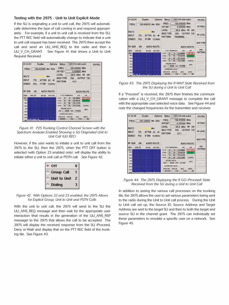
Testing with the 2975 - Unit to Unit Explicit Mode
If the SU is originating a unit to unit call, the 2975 will automati-
cally determine the type of call coming in and respond appropri-
ately. For example, if a unit to unit call is received from the SU,
the PTT REC field will automatically change to indicate that a unit
to unit call request has been received. The 2975 then accept the
call and send an UU_ANS_REQ to the radio and then a
UU_V_CH_GRANT. See Figure 41 that shows a Unit to Unit
Request Received.
Figure 41: P25 Trunking Control Channel Screen with the
Spectrum Analyzer Enabled Showing a SU Originated Unit to
Unit Call (UU REC)
However, if the user wants to initiate a unit to unit call from the
2975 to the SU, then the 2975, when the PTT OFF button is
selected (with Option 23 enabled only), will display the ability to
initiate either a unit to unit call or PSTN call. See Figure 42.
Figure 42: With Options 22 and 23 enabled, the 2975 Allows
for Explicit Group, Unit to Unit and PSTN Calls
With the unit to unit call, the 2975 will send to the SU the
UU_ANS_REQ message and then wait for the appropriate user
interaction (that results in the generation of the UU_ANS_RSP
message) to the 2975 that allows the call to be accepted. The
2975 will display the received response from the SU (Proceed,
Deny or Wait) and display that on the PTT REC field of the trunk-
ing tile. See Figure 43.
Figure 43: The 2975 Displaying the R WAIT State Received from
the SU during a Unit to Unit Call
If a "Proceed" is received, the 2975 then finishes the communi-
cation with a UU_V_CH_GRANT message to complete the call
with the appropriate user selected voice data. See Figure 44 and
note the changed frequencies for the transmitter and receiver.
Figure 44: The 2975 Displaying the R GO (Proceed) State
Received from the SU during a Unit to Unit Call
In addition to seeing the various call processes on the trunking
tile, the 2975 allows the user to set various parameters being sent
to the radio during the Unit to Unit call process. During the Unit
to Unit call set up, the Source ID, Source Address and Target
Address are sent to the target SU and then to both the target and
source SU in the channel grant. The 2975 can individually set
these parameters to emulate a specific user on a network. See
Figure 45.
For the very latest specifications visit www.aeroflex.com
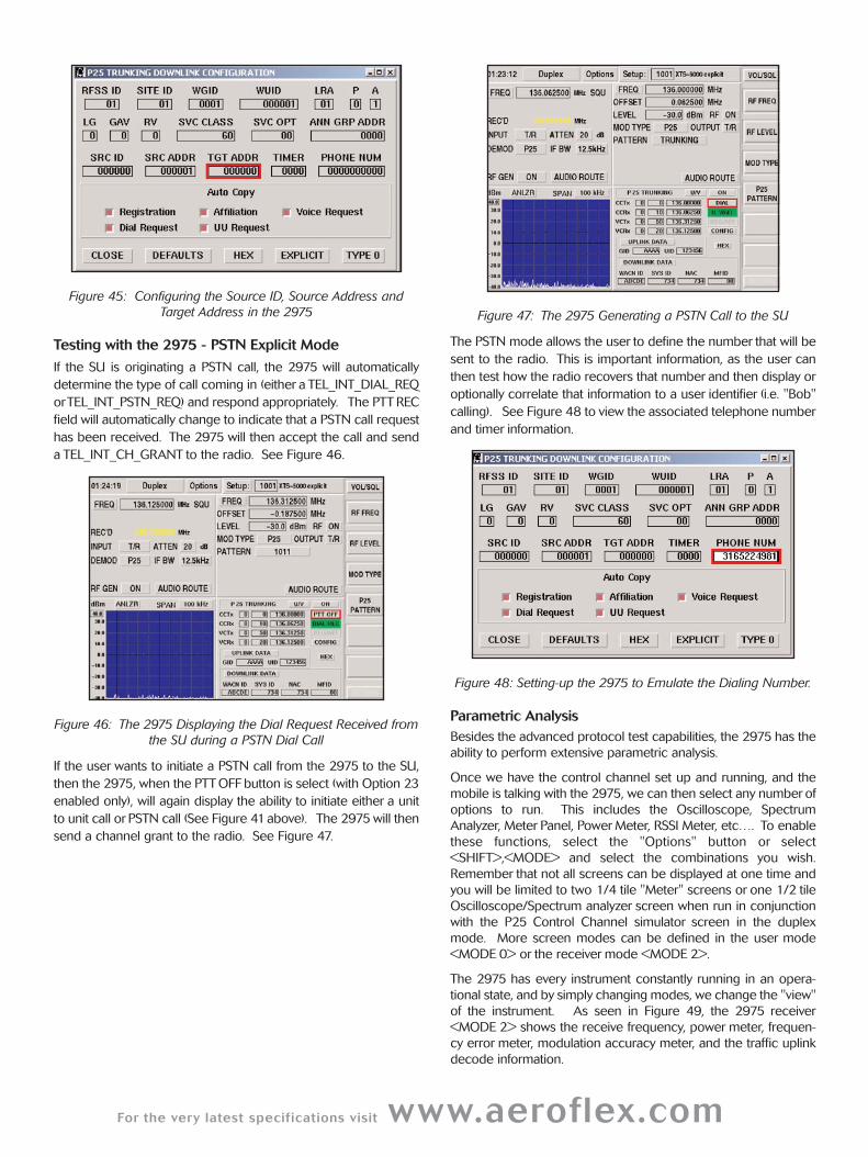
Figure 45: Configuring the Source ID, Source Address and
Target Address in the 2975
Testing with the 2975 - PSTN Explicit Mode
If the SU is originating a PSTN call, the 2975 will automatically
determine the type of call coming in (either a TEL_INT_DIAL_REQ
orTEL_INT_PSTN_REQ) and respond appropriately. The PTT REC
field will automatically change to indicate that a PSTN call request
has been received. The 2975 will then accept the call and send
a TEL_INT_CH_GRANT to the radio. See Figure 46.
Figure 46: The 2975 Displaying the Dial Request Received from
the SU during a PSTN Dial Call
If the user wants to initiate a PSTN call from the 2975 to the SU,
then the 2975, when the PTT OFF button is select (with Option 23
enabled only), will again display the ability to initiate either a unit
to unit call or PSTN call (See Figure 41 above). The 2975 will then
send a channel grant to the radio. See Figure 47.
Figure 47: The 2975 Generating a PSTN Call to the SU
The PSTN mode allows the user to define the number that will be
sent to the radio. This is important information, as the user can
then test how the radio recovers that number and then display or
optionally correlate that information to a user identifier (i.e. "Bob"
calling). See Figure 48 to view the associated telephone number
and timer information.
Figure 48: Setting-up the 2975 to Emulate the Dialing Number.
Parametric Analysis
Besides the advanced protocol test capabilities, the 2975 has the
ability to perform extensive parametric analysis.
Once we have the control channel set up and running, and the
mobile is talking with the 2975, we can then select any number of
options to run. This includes the Oscilloscope, Spectrum
Analyzer, Meter Panel, Power Meter, RSSI Meter, etc…. To enable
these functions, select the "Options" button or select
<SHIFT>,<MODE> and select the combinations you wish.
Remember that not all screens can be displayed at one time and
you will be limited to two 1/4 tile "Meter" screens or one 1/2 tile
Oscilloscope/Spectrum analyzer screen when run in conjunction
with the P25 Control Channel simulator screen in the duplex
mode. More screen modes can be defined in the user mode
<MODE 0> or the receiver mode <MODE 2>.
The 2975 has every instrument constantly running in an opera-
tional state, and by simply changing modes, we change the "view"
of the instrument. As seen in Figure 49, the 2975 receiver
<MODE 2> shows the receive frequency, power meter, frequen-
cy error meter, modulation accuracy meter, and the traffic uplink
decode information.
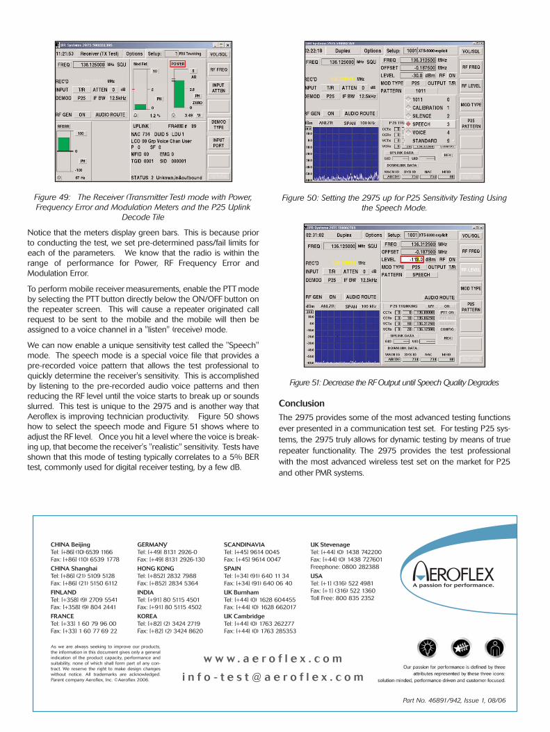
Figure 49: The Receiver (Transmitter Test) mode with Power,
Frequency Error and Modulation Meters and the P25 Uplink
Decode Tile
Notice that the meters display green bars. This is because prior
to conducting the test, we set pre-determined pass/fail limits for
each of the parameters. We know that the radio is within the
range of performance for Power, RF Frequency Error and
Modulation Error.
To perform mobile receiver measurements, enable the PTT mode
by selecting the PTT button directly below the ON/OFF button on
the repeater screen. This will cause a repeater originated call
request to be sent to the mobile and the mobile will then be
assigned to a voice channel in a "listen" (receive) mode.
We can now enable a unique sensitivity test called the "Speech"
mode. The speech mode is a special voice file that provides a
pre-recorded voice pattern that allows the test professional to
quickly determine the receiver's sensitivity. This is accomplished
by listening to the pre-recorded audio voice patterns and then
reducing the RF level until the voice starts to break up or sounds
slurred. This test is unique to the 2975 and is another way that
Aeroflex is improving technician productivity. Figure 50 shows
how to select the speech mode and Figure 51 shows where to
adjust the RF level. Once you hit a level where the voice is break-
ing up, that become the receiver's "realistic" sensitivity. Tests have
shown that this mode of testing typically correlates to a 5% BER
test, commonly used for digital receiver testing, by a few dB.
Figure 50: Setting the 2975 up for P25 Sensitivity Testing Using
the Speech Mode.
Figure 51: Decrease the RF Output until Speech Quality Degrades
Conclusion
The 2975 provides some of the most advanced testing functions
ever presented in a communication test set. For testing P25 sys-
tems, the 2975 truly allows for dynamic testing by means of true
repeater functionality. The 2975 provides the test professional
with the most advanced wireless test set on the market for P25
and other PMR systems.
Part No. 46891/942, Issue 1, 08/06
CHINA Beijing
Tel: [+86] (10) 6539 1166
Fax: [+86] (10) 6539 1778
CHINA Shanghai
Tel: [+86] (21) 5109 5128
Fax: [+86] (21) 5150 6112
FINLAND
Tel: [+358] (9) 2709 5541
Fax: [+358] (9) 804 2441
FRANCE
Tel: [+33] 1 60 79 96 00
Fax: [+33] 1 60 77 69 22
GERMANY
Tel: [+49] 8131 2926-0
Fax: [+49] 8131 2926-130
HONG KONG
Tel: [+852] 2832 7988
Fax: [+852] 2834 5364
INDIA
Tel: [+91] 80 5115 4501
Fax: [+91] 80 5115 4502
KOREA
Tel: [+82] (2) 3424 2719
Fax: [+82] (2) 3424 8620
SCANDINAVIA
Tel: [+45] 9614 0045
Fax: [+45] 9614 0047
SPAIN
Tel: [+34] (91) 640 11 34
Fax: [+34] (91) 640 06 40
UK Burnham
Tel: [+44] (0) 1628 604455
Fax: [+44] (0) 1628 662017
UK Cambridge
Tel: [+44] (0) 1763 262277
Fax: [+44] (0) 1763 285353
UK Stevenage
Tel: [+44] (0) 1438 742200
Fax: [+44] (0) 1438 727601
Freephone: 0800 282388
USA
Tel: [+1] (316) 522 4981
Fax: [+1] (316) 522 1360
Toll Free: 800 835 2352
w w w . a e r o f l e x . c o m
i n f o - t e s t @ a e r o f l e x . c o m
As we are always seeking to improve our products,
the information in this document gives only a general
indication of the product capacity, performance and
suitability, none of which shall form part of any con-
tract. We reserve the right to make design changes
without notice. All trademarks are acknowledged.
Parent company Aeroflex, Inc. ©Aeroflex 2006.