understanding centrifugal pump
TRANSCRIPT
7/26/2019 Understanding Centrifugal Pump
http://slidepdf.com/reader/full/understanding-centrifugal-pump 1/7
22 www.aiche.org/cep October 2010 CEP
Back to Basics
Pumps provide a wide range of services in a typical
chemical process industries (CPI) plant. They are
available with a variety of head/flow combinations
and are expected to operate under a variety of process
conditions, including many different temperatures, toxici-
ties, and viscosities, and the fluids they handle may be
harmless, corrosive, or vapor-forming. Thus, selecting pumps for CPI applications can be challenging. This
article will help the novice engineer develop an under-
standing of pumping issues that can lead to more effective
dialog during the early stages of a project, and ultimately
improve the ef ficiency of the requisitioning process and
the long-term reliability of the equipment.
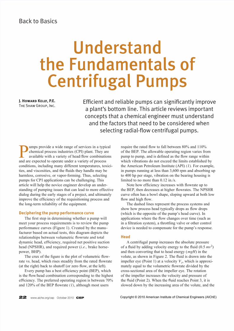
Deciphering the pump performance curve
The first step in determining whether a pump will
meet your process requirements is to review the pump
performance curves (Figure 1). Created by the manu-
facturer based on actual tests, this diagram depicts therelationships between volumetric flowrate and total
dynamic head, ef ficiency, required net positive suction
head (NPSHR), and required power (i.e., brake horse-
power, BHP).
The crux of the figure is the plot of volumetric flow-
rate vs. head, which rises steadily from the rated flowrate
(at the right) back to shutoff (or zero flow, at the left).
Every pump has a best ef ficiency point (BEP), which
is the flow/head combination corresponding to the highest
ef ficiency. The preferred operating region is between 70%
and 120% of the BEP flowrate (1), although most users
require the rated flow to fall between 80% and 110%
of the BEP. The allowable operating region varies from
pump to pump, and is defined as the flow range within
which vibrations do not exceed the limits established by
the American Petroleum Institute (API) (1). For example,
in pumps running at less than 3,600 rpm and absorbing up
to 400 hp per stage, vibration on the bearing housing islimited to no more than 0.12 in./s.
Note how ef ficiency increases with flowrate up to
the BEP, then decreases at higher flowrates. The NPSHR
curve often has a bowl shape, sloping upward at both low
flow and high flow.
The dashed lines represent the process systems and
show how process head typically drops as flow drops
(which is the opposite of the pump’s head curve). In
applications where the flow changes over time (such as
in a filtration system), a throttling valve or other control
device is needed to compensate for the pump’s response.
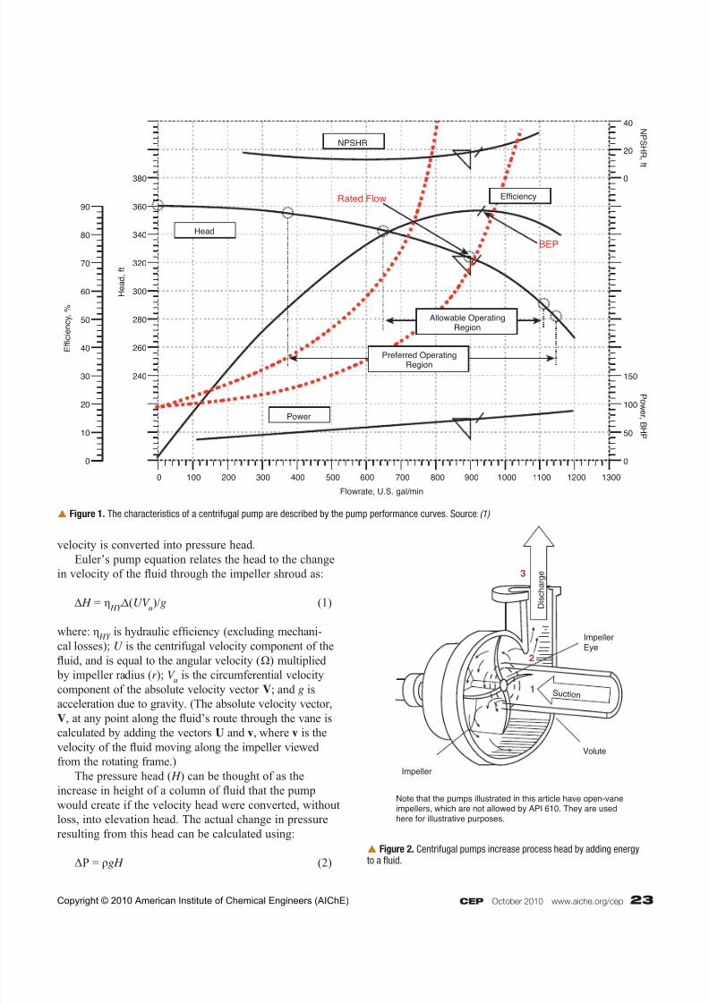
Head
A centrifugal pump increases the absolute pressure
of a fluid by adding velocity energy to the fluid (0.5 mv2)
and then converting that to head energy (mgH ) in the
volute, as shown in Figure 2. The fluid is drawn into the
impeller eye (Point 1) at a velocity V 1, which is approxi-
mately equal to the volumetric flowrate divided by the
cross-sectional area of the impeller eye. The rotation
of the impeller increases the velocity and pressure of
the fluid (Point 2). When the fluid reaches Point 3, it is
slowed down by the increasing area of the volute, and the
Efficient and reliable pumps can significantly improve
a plant’s bottom line. This article reviews important
concepts that a chemical engineer must understandand the factors that need to be considered when
selecting radial-flow centrifugal pumps.
J. Howard Kelly, P.E.
The Shaw Group, Inc.
Understandthe Fundamentals ofCentrifugal Pumps
Copyright © 2010 American Institute of Chemical Engineers (AIChE)
7/26/2019 Understanding Centrifugal Pump
http://slidepdf.com/reader/full/understanding-centrifugal-pump 2/7
CEP October 2010 www.aiche.org/cep 23
velocity is converted into pressure head.
Euler’s pump equation relates the head to the change
in velocity of the fluid through the impeller shroud as:
∆ H = η HY ∆(UV
u)/g (1)
where: η HY
is hydraulic ef ficiency (excluding mechani-
cal losses); U is the centrifugal velocity component of the
fluid, and is equal to the angular velocity (Ω) multiplied
by impeller radius (r ); V u is the circumferential velocity
component of the absolute velocity vector V; and g is
acceleration due to gravity. (The absolute velocity vector,V, at any point along the fluid’s route through the vane is
calculated by adding the vectors U and v, where v is the
velocity of the fluid moving along the impeller viewed
from the rotating frame.)
The pressure head ( H ) can be thought of as the
increase in height of a column of fluid that the pump
would create if the velocity head were converted, without
loss, into elevation head. The actual change in pressure
resulting from this head can be calculated using:
ΔP = ρgH (2)
Efficiency
Head
380
360
340
320
300
280
260
240
70
80
90
60
50
40
30
20
10
0 0
0 100 200 300 400 500 600 700 800 900 1000 1100 1200 1300
50
100
150
0
20
40
Power
NPSHR
Rated Flow
BEP
NP S HR ,f t
P ow er ,B HP
Flowrate, U.S. gal/min
E
f f i c i e n c y , %
H e a d , f t
Preferred OperatingRegion
Allowable OperatingRegion
Figure 1. The characteristics of a centrifugal pump are described by the pump performance curves. Source: (1)
D i s c h a r g e
Suc t ion
Impeller
Eye
Volute
Impeller
Note that the pumps illustrated in this article have open-vaneimpellers, which are not allowed by API 610. They are used
here for illustrative purposes.
1
2
3
Figure 2. Centrifugal pumps increase process head by adding energyto a fluid.
Copyright © 2010 American Institute of Chemical Engineers (AIChE)
7/26/2019 Understanding Centrifugal Pump
http://slidepdf.com/reader/full/understanding-centrifugal-pump 3/7
24 www.aiche.org/cep October 2010 CEP
Back to Basics
where ΔP is the change in pressure and ρ is the density of
the fluid.
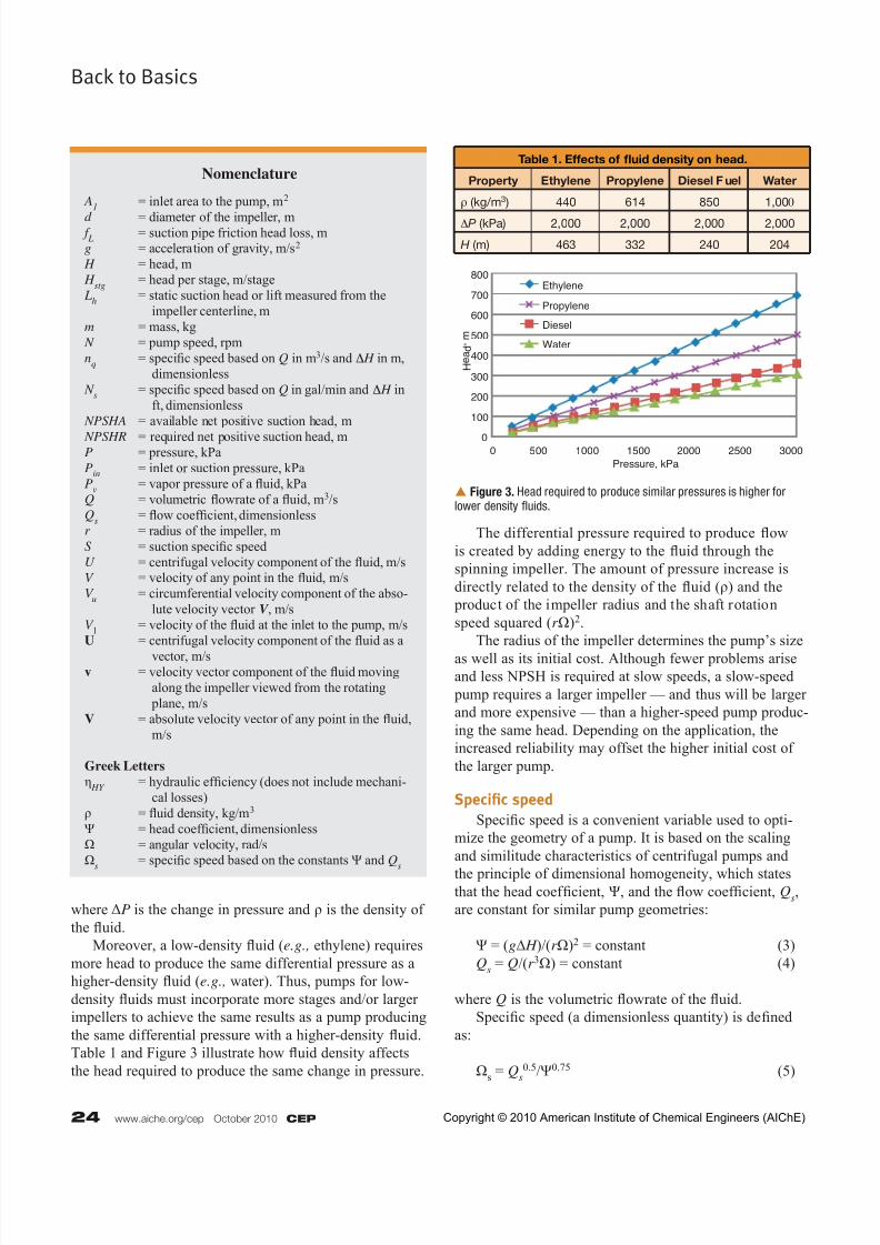
Moreover, a low-density fluid (e.g., ethylene) requires
more head to produce the same differential pressure as a
higher-density fluid (e.g., water). Thus, pumps for low-
density fluids must incorporate more stages and/or larger
impellers to achieve the same results as a pump producing
the same differential pressure with a higher-density fluid.
Table 1 and Figure 3 illustrate how fluid density affects
the head required to produce the same change in pressure.
The differential pressure required to produce flow
is created by adding energy to the fluid through the
spinning impeller. The amount of pressure increase is
directly related to the density of the fluid (ρ) and the
product of the impeller radius and the shaft rotation
speed squared (r Ω)2.
The radius of the impeller determines the pump’s size
as well as its initial cost. Although fewer problems ariseand less NPSH is required at slow speeds, a slow-speed
pump requires a larger impeller — and thus will be larger
and more expensive — than a higher-speed pump produc-
ing the same head. Depending on the application, the
increased reliability may offset the higher initial cost of
the larger pump.
Specific speed
Specific speed is a convenient variable used to opti-
mize the geometry of a pump. It is based on the scaling
and similitude characteristics of centrifugal pumps and
the principle of dimensional homogeneity, which statesthat the head coef ficient, Ψ, and the flow coef ficient, Q
s,
are constant for similar pump geometries:
Ψ = (g∆ H )/(r Ω)2 = constant (3)
Qs = Q/(r 3Ω) = constant (4)
where Q is the volumetric flowrate of the fluid.
Specific speed (a dimensionless quantity) is defined
as:
Ωs = Q
s0.5/Ψ0.75 (5)
Table 1. Effects of fluid density on head.
Property Ethylene Propylene Diesel F uel Water
ρ (kg/m3 ) 440 614 850 1,000
ΔP (kPa) 2,000 2,000 2,000 2,000
H (m) 463 332 240 204
0
100
200
300
400
500
600
700
800
0 500 1000 1500 2000 2500 3000
Ethylene
Propylene
Diesel
Water
Pressure, kPa
H e
a d , m
Figure 3. Head required to produce similar pressures is higher forlower density fluids.
Nomenclature
A1 = inlet area to the pump, m2
d = diameter of the impeller, m f L
= suction pipe friction head loss, mg = acceleration of gravity, m/s2
H = head, m
H stg
= head per stage, m/stage
Lh = static suction head or lift measured from the
impeller centerline, m
m = mass, kg
N = pump speed, rpm
nq = specific speed based on Q in m3/s and Δ H in m,
dimensionless
N s = specific speed based on Q in gal/min and Δ H in
ft, dimensionless
NPSHA = available net positive suction head, m
NPSHR = required net positive suction head, mP = pressure, kPa
Pin
= inlet or suction pressure, kPa
Pv = vapor pressure of a fluid, kPa
Q = volumetric flowrate of a fluid, m3/sQ
s = flow coef ficient, dimensionless
r = radius of the impeller, mS = suction specific speedU = centrifugal velocity component of the fluid, m/sV = velocity of any point in the fluid, m/s
V u = circumferential velocity component of the abso-
lute velocity vector V , m/s
V 1 = velocity of the fluid at the inlet to the pump, m/s
U = centrifugal velocity component of the fluid as a
vector, m/sv = velocity vector component of the fluid moving
along the impeller viewed from the rotating
plane, m/s
V = absolute velocity vector of any point in the fluid,
m/s
Greek Letters
η HY
= hydraulic ef ficiency (does not include mechani-
cal losses)
ρ = fluid density, kg/m3
Ψ = head coef ficient, dimensionless
Ω = angular velocity, rad/s
Ωs = specific speed based on the constants Ψ and Q
s
Copyright © 2010 American Institute of Chemical Engineers (AIChE)
7/26/2019 Understanding Centrifugal Pump
http://slidepdf.com/reader/full/understanding-centrifugal-pump 4/7
CEP October 2010 www.aiche.org/cep 25
For convenience, specific speed is generally repre-
sented in terms of pump speed ( N), volumetric flowrate
(Q), and head (∆ H ):
nq = NQ0.5/∆ H 0.75 (6)
In Eq. 6, specific speed is represented by nq, and it is
calculated using values of Q in m3/s and Δ H in m. When
English units are used for flowrate and head (Q in gal/min
and Δ H in ft), the equation has the same form but specific
speed is represented by N s:
N s = NQ0.5/∆ H 0.75 (7)
The relationship between nq and N
s is:
nq = N
s / 51.64 (8)
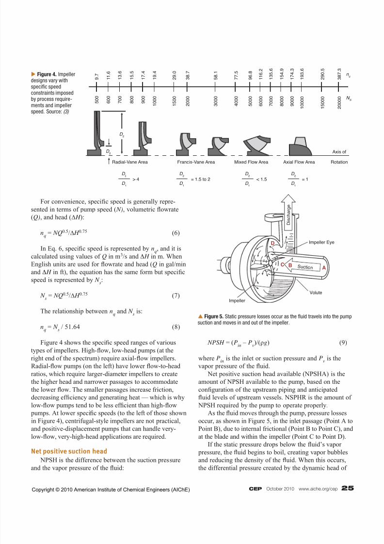
Figure 4 shows the specific speed ranges of various
types of impellers. High-flow, low-head pumps (at the
right end of the spectrum) require axial-flow impellers.
Radial-flow pumps (on the left) have lower flow-to-head
ratios, which require larger-diameter impellers to create
the higher head and narrower passages to accommodatethe lower flow. The smaller passages increase friction,
decreasing ef ficiency and generating heat — which is why
low-flow pumps tend to be less ef ficient than high-flow
pumps. At lower specific speeds (to the left of those shown
in Figure 4), centrifugal-style impellers are not practical,
and positive-displacement pumps that can handle very-
low-flow, very-high-head applications are required.
Net positive suction head
NPSH is the difference between the suction pressure
and the vapor pressure of the fluid:
NPSH = (Pin
– Pv)/(ρg) (9)
where Pin
is the inlet or suction pressure and Pv is the
vapor pressure of the fluid.
Net positive suction head available (NPSHA) is the
amount of NPSH available to the pump, based on theconfiguration of the upstream piping and anticipated
fluid levels of upstream vessels. NSPHR is the amount of
NPSH required by the pump to operate properly.
As the fluid moves through the pump, pressure losses
occur, as shown in Figure 5, in the inlet passage (Point A to
Point B), due to internal frictional (Point B to Point C), and
at the blade and within the impeller (Point C to Point D).
If the static pressure drops below the fluid’s vapor
pressure, the fluid begins to boil, creating vapor bubbles
and reducing the density of the fluid. When this occurs,
the differential pressure created by the dynamic head of
5 0 0 6 0 0 7 0 0 8 0 0 9 0 0
1 0 0 0
1 5 0 0
2 0 0 0
3 0 0 0
4 0 0 0
5 0 0 0
6 0 0 0
7 0 0 0
8 0 0 0
9 0 0 0
1 0 0 0 0
1 5 0 0 0
2 0 0 0 0
D 2
D 2
D 2
> 4 = 1.5 to 2 < 1.5 = 1
D 2
Radial-Vane Area Francis-Vane Area Mixed Flow Area Axial Flow Area
Axis of
Rotation
D 2
D 2
D 1
D 1
D 1
D 1
9 . 7 1 1 . 6
1 3 . 6
1 5 . 5
1 7 . 4
1 9 . 4
2 9 . 0
3 8 . 7
5 8 . 1
7 7 . 5
9 6 . 8
1 1 6 . 2
1 3 5 . 6
1 5 4 . 9
1 7 4 . 3
1 9 3 . 6
2 9 0 . 5
3 8 7 . 3
N S
n q Figure 4. Impeller
designs vary withspecific speed
constraints imposedby process require-ments and impellerspeed. Source: (3)
D i s c h a r g e
Suc t ion
Impeller Eye
Volute
Impeller
ABC
D
Figure 5. Static pressure losses occur as the fluid travels into the pumpsuction and moves in and out of the impeller.
Copyright © 2010 American Institute of Chemical Engineers (AIChE)
7/26/2019 Understanding Centrifugal Pump
http://slidepdf.com/reader/full/understanding-centrifugal-pump 5/7
26 www.aiche.org/cep October 2010 CEP
Back to Basics
the impeller decreases (Eq. 2). API 610 defines NPSHR
as the amount of suction head needed to limit head loss
at the first stage of the pump to 3% (using water as thetest fluid). Although hydrocarbons generally require less
NPSH than water (4), reduction factors for hydrocarbons
are not allowed by API.
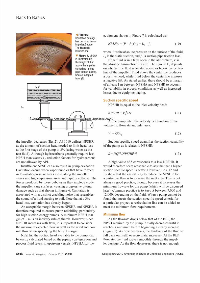
Insuf ficient NPSH can also result in pump cavitation.
Cavitation occurs when vapor bubbles that have formed
in low-static-pressure areas move along the impeller
vanes into higher-pressure areas and rapidly collapse. The
forces produced by these bubbles as they implode erode
the impeller vane surfaces, causing progressive pitting
damage such as that shown in Figure 6. Cavitation is
associated with a distinct crackling noise that resembles
the sound of a fluid starting to boil. Note that at a 3%head loss, cavitation has already begun.
An acceptable margin between NPSHR and NPSHA is
therefore required to ensure pump reliability, particularly
for high-suction-energy pumps. A minimum NPSH mar-
gin of 1 m is an industry rule of thumb. However, since
NPSHR increases with flow, it is important to consider
the maximum expected flow as well as the rated and nor-
mal flow when specifying the NPSH margin.
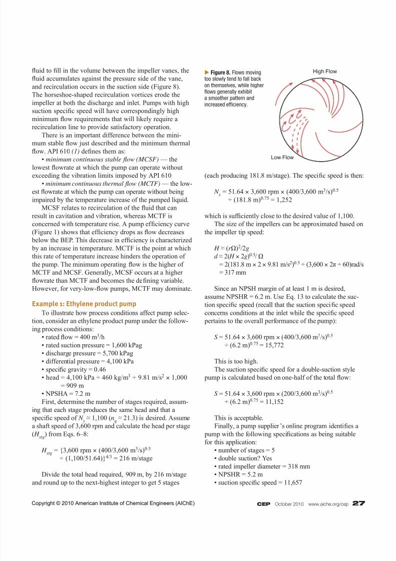
NPSHA, the suction head available to the pump, can
be easily calculated based on the piping configuration and
process fluid levels in upstream vessels. NPSHA for the
equipment shown in Figure 7 is calculated as:
NPSHA = (P – Pv)/ρg + L
h – f
L (10)
where P is the absolute pressure on the surface of the fluid,
Lh is the static suction, and f
L is suction pipe friction loss.
If the fluid is in a tank open to the atmosphere, P is
the absolute barometric pressure. The sign of Lh depends
on whether the fluid is located above or below the center-
line of the impeller: Fluid above the centerline produces
a positive head, while fluid below the centerline imposes
a negative lift. As stated earlier, there should be a margin
of at least 1 m between NPSHA and NPSHR to account
for variability in process conditions as well as increased
losses due to equipment aging.
Suction specific speed NPSHR is equal to the inlet velocity head:
NPSHR = V 12/2g (11)
At the pump inlet, the velocity is a function of the
volumetric flowrate and inlet area:
V 1 = Q/ A
1 (12)
Suction specific speed quantifies the suction capability
of the pump as it relates to NPSHR:
S = NQ0.5/ NPSHR0.75 (13)
A high value of S corresponds to a low NPSHR. It
would therefore seem reasonable to assume that a higher
suction specific speed is better. However, Eqs. 12 and
13 show that the easiest way to reduce the NPSHR for
a particular flow is to increase the inlet area. This is not
always a good practice, though, because it increases the
minimum flowrate for the pump (which will be discussed
later). Common practice is to keep S between 7,000 and
12,000, depending on the fluid. When a pump cannot be
found that meets the suction specific speed criteria fora particular project, a recirculation line can be added to
meet the minimum flow requirements.
Minimum flow
As the flowrate drops below that of the BEP, the
NPSH required by the pump initially decreases until it
reaches a minimum before beginning a steady increase
(Figure 1). As flow decreases, the tendency of the fluid to
fall back on itself, or recirculate, increases. At the BEP
flowrate, the fluid moves smoothly through the impel-
ler passage. As the flow decreases, there is not enough
Cavitation Damage
L e a d i n
g E
d g e
o f V a
n e Figure 7. NPSHAis illustrated bythe height of fluidabove the impellercenterline (minuspipe friction losses).Source: Adaptedfrom (2).
Figure 6. Cavitation damagehas occurred on animpeller. Source:The HydraulicInstitute, Inc.
P
Lh
CLCopyright © 2010 American Institute of Chemical Engineers (AIChE)
Copyright © 2010 American Institute of Chemical Engineers (AIChE)
7/26/2019 Understanding Centrifugal Pump
http://slidepdf.com/reader/full/understanding-centrifugal-pump 6/7
CEP October 2010 www.aiche.org/cep 27
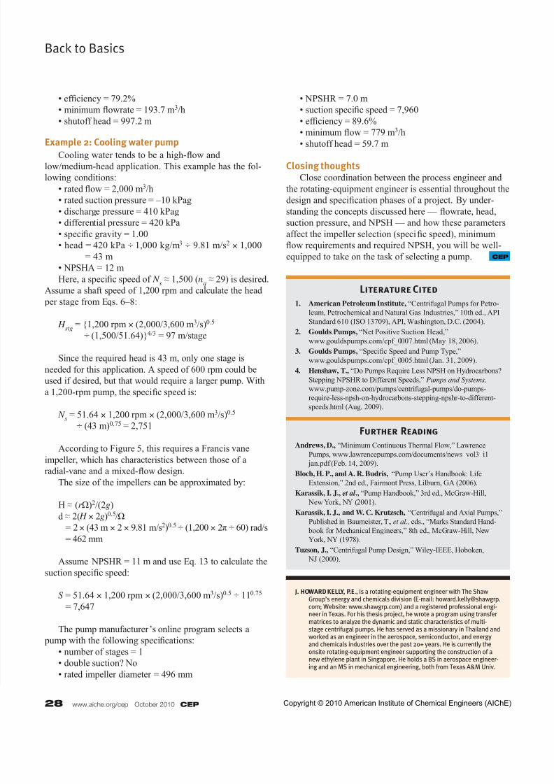
fluid to fill in the volume between the impeller vanes, the
fluid accumulates against the pressure side of the vane,
and recirculation occurs in the suction side (Figure 8).
The horseshoe-shaped recirculation vortices erode theimpeller at both the discharge and inlet. Pumps with high
suction specific speed will have correspondingly high
minimum flow requirements that will likely require a
recirculation line to provide satisfactory operation.
There is an important difference between the mini-
mum stable flow just described and the minimum thermal
flow. API 610 (1) defines them as:
• minimum continuous stable fl ow (MCSF) — the
lowest flowrate at which the pump can operate without
exceeding the vibration limits imposed by API 610
• minimum continuous thermal fl ow (MCTF) — the low-
est flowrate at which the pump can operate without being
impaired by the temperature increase of the pumped liquid.
MCSF relates to recirculation of the fluid that can
result in cavitation and vibration, whereas MCTF is
concerned with temperature rise. A pump ef ficiency curve
(Figure 1) shows that ef ficiency drops as flow decreases
below the BEP. This decrease in ef ficiency is characterized
by an increase in temperature. MCTF is the point at which
this rate of temperature increase hinders the operation of
the pump. The minimum operating flow is the higher of
MCTF and MCSF. Generally, MCSF occurs at a higher
flowrate than MCTF and becomes the defining variable.
However, for very-low-flow pumps, MCTF may dominate.
Example 1: Ethylene product pump
To illustrate how process conditions affect pump selec-
tion, consider an ethylene product pump under the follow-
ing process conditions:
• rated flow = 400 m3/h
• rated suction pressure = 1,600 kPag
• discharge pressure = 5,700 kPag
• differential pressure = 4,100 kPa
• specific gravity = 0.46
• head = 4,100 kPa ÷ 460 kg/m3 ÷ 9.81 m/s2 × 1,000
= 909 m
• NPSHA = 7.2 m First, determine the number of stages required, assum-
ing that each stage produces the same head and that a
specific speed of N s ≈ 1,100 (n
q ≈ 21.3) is desired. Assume
a shaft speed of 3,600 rpm and calculate the head per stage
( H stg
) from Eqs. 6–8:
H stg
= {3,600 rpm × (400/3,600 m3/s)0.5
÷ (1,100/51.64)}4/3 = 216 m/stage
Divide the total head required, 909 m, by 216 m/stage
and round up to the next-highest integer to get 5 stages
(each producing 181.8 m/stage). The specific speed is then:
N s
= 51.64 × 3,600 rpm × (400/3,600 m3/s)0.5
÷ (181.8 m)0.75 = 1,252
which is suf ficiently close to the desired value of 1,100.
The size of the impellers can be approximated based on
the impeller tip speed:
H ≈ (r Ω)2/2g
d ≈ 2( H × 2g)0.5/Ω
= 2(181.8 m × 2 × 9.81 m/s2)0.5 ÷ (3,600 × 2π ÷ 60)rad/s
= 317 mm
Since an NPSH margin of at least 1 m is desired,
assume NPSHR = 6.2 m. Use Eq. 13 to calculate the suc-tion specific speed (recall that the suction specific speed
concerns conditions at the inlet while the specific speed
pertains to the overall performance of the pump):
S = 51.64 × 3,600 rpm × (400/3,600 m3/s)0.5
÷ (6.2 m)0.75 = 15,772
This is too high.
The suction specific speed for a double-suction style
pump is calculated based on one-half of the total flow:
S = 51.64 × 3,600 rpm × (200/3,600 m3/s)0.5 ÷ (6.2 m)0.75 = 11,152
This is acceptable.
Finally, a pump supplier’s online program identifies a
pump with the following specifications as being suitable
for this application:
• number of stages = 5
• double suction? Yes
• rated impeller diameter = 318 mm
• NPSHR = 5.2 m
• suction specific speed = 11,657
High Flow
Low Flow
Figure 8. Flows movingtoo slowly tend to fall backon themselves, while higherflows generally exhibit
a smoother pattern andincreased efficiency.
Copyright © 2010 American Institute of Chemical Engineers (AIChE)
7/26/2019 Understanding Centrifugal Pump
http://slidepdf.com/reader/full/understanding-centrifugal-pump 7/7
28 www.aiche.org/cep October 2010 CEP
Back to Basics
• ef ficiency = 79.2%
• minimum flowrate = 193.7 m3/h
• shutoff head = 997.2 m
Example 2: Cooling water pump
Cooling water tends to be a high-flow and
low/medium-head application. This example has the fol-
lowing conditions:
• rated flow = 2,000 m3/h
• rated suction pressure = –10 kPag
• discharge pressure = 410 kPag
• differential pressure = 420 kPa
• specific gravity = 1.00
• head = 420 kPa ÷ 1,000 kg/m3 ÷ 9.81 m/s2 × 1,000
= 43 m
• NPSHA = 12 m
Here, a specific speed of N s ≈ 1,500 (n
q ≈ 29) is desired.
Assume a shaft speed of 1,200 rpm and calculate the head
per stage from Eqs. 6–8:
H stg
= {1,200 rpm × (2,000/3,600 m3/s)0.5
÷ (1,500/51.64)}4/3 = 97 m/stage
Since the required head is 43 m, only one stage is
needed for this application. A speed of 600 rpm could be
used if desired, but that would require a larger pump. With
a 1,200-rpm pump, the specific speed is:
N s = 51.64 × 1,200 rpm × (2,000/3,600 m3/s)0.5 ÷ (43 m)0.75 = 2,751
According to Figure 5, this requires a Francis vane
impeller, which has characteristics between those of a
radial-vane and a mixed-flow design.
The size of the impellers can be approximated by:
H ≈ (r Ω)2/(2g)
d ≈ 2( H × 2g)0.5/Ω
= 2× (43 m × 2 × 9.81 m/s2)0.5 ÷ (1,200 × 2π ÷ 60) rad/s
= 462 mm
Assume NPSHR = 11 m and use Eq. 13 to calculate the
suction specific speed:
S = 51.64 × 1,200 rpm × (2,000/3,600 m3/s)0.5 ÷ 110.75
= 7,647
The pump manufacturer’s online program selects a
pump with the following specifications:
• number of stages = 1
• double suction? No
• rated impeller diameter = 496 mm
• NPSHR = 7.0 m
• suction specific speed = 7,960
• ef ficiency = 89.6%
• minimumfl
ow = 779 m
3
/h • shutoff head = 59.7 m
Closing thoughts Close coordination between the process engineer and
the rotating-equipment engineer is essential throughout the
design and specification phases of a project. By under-
standing the concepts discussed here — flowrate, head,
suction pressure, and NPSH — and how these parameters
affect the impeller selection (specific speed), minimum
flow requirements and required NPSH, you will be well-
equipped to take on the task of selecting a pump.
J. HOWARD KELLY, P.E., is a rotating-equipment engineer with The ShawGroup’s energy and chemicals division (E-mail: [email protected]; Website: www.shawgrp.com) and a registered professional engi-neer in Texas. For his thesis project, he wrote a program using transfermatrices to analyze the dynamic and static characteristics of multi-stage centrifugal pumps. He has served as a missionary in Thailand andworked as an engineer in the aerospace, semiconductor, and energyand chemicals industries over the past 20+ years. He is currently theonsite rotating-equipment engineer supporting the construction of anew ethylene plant in Singapore. He holds a BS in aerospace engineer-ing and an MS in mechanical engineering, both from Texas A&M Univ.
Literature Cited
1. American Petroleum Institute, “Centrifugal Pumps for Petro-
leum, Petrochemical and Natural Gas Industries,” 10th ed., API
Standard 610 (ISO 13709), API, Washington, D.C. (2004).
2. Goulds Pumps, “Net Positive Suction Head,”
www.gouldspumps.com/cpf_0007.html (May 18, 2006).
3. Goulds Pumps, “Specific Speed and Pump Type,”
www.gouldspumps.com/cpf_0005.html (Jan. 31, 2009).
4. Henshaw, T., “Do Pumps Require Less NPSH on Hydrocarbons?
Stepping NPSHR to Different Speeds,” Pumps and Systems,
www.pump-zone.com/pumps/centrifugal-pumps/do-pumps-
require-less-npsh-on-hydrocarbons-stepping-npshr-to-different-
speeds.html (Aug. 2009).
Further Reading
Andrews, D., “Minimum Continuous Thermal Flow,” Lawrence
Pumps, www.lawrencepumps.com/documents/news_vol3_i1_
jan.pdf (Feb. 14, 2009).
Bloch, H. P., and A. R. Budris, “Pump User’s Handbook: Life
Extension,” 2nd ed., Fairmont Press, Lilburn, GA (2006).
Karassik, I. J., et al ., “Pump Handbook,” 3rd ed., McGraw-Hill,
New York, NY (2001).
Karassik, I. J., and W. C. Krutzsch, “Centrifugal and Axial Pumps,”
Published in Baumeister, T., et al., eds., “Marks Standard Hand-
book for Mechanical Engineers,” 8th ed., McGraw-Hill, New
York, NY (1978).
Tuzson, J., “Centrifugal Pump Design,” Wiley-IEEE, Hoboken, NJ (2000).
CEP
Copyright © 2010 American Institute of Chemical Engineers (AIChE)