unclassified - defense technical information center · unclassified unclassified ... impossible or...
TRANSCRIPT
UNCLASSIFIED
UNCLASSIFIED Distribution A. Approved for public release.
Transparent Armor for the New Standard in Transparent Battle Performance
Kathie Leighton(1), John Carberry(1), Wiktor Serafin(1), Terrance Avery(2), Douglas Templeton(2)
(1) SCHOTT DiamondView Armor Products, LLC, 1515 Garnet Mine Road, Boothwyn PA 19061
(2) TARDEC 6501 E. 11 Mile Road Warren, MI 48397-5000
ABSTRACT
Armor Transparent Purchase Description (ATPD) 2352 revision P1 was issued in July 2008 to
create a new standard for transparent armor aimed at improving battlefield performance, maintenance
costs, equipment survivability, and general durability based on data collected from performance of
transparent armor in the battlefield. A transparent armor specifically focused on satisfying all of the
ATPD 2352 requirements was invented, developed, and commercialized. A Cooperative Research and
Development Agreement with TARDEC resulted in evaluating armor to all the metrics of ATPD 2352.
This paper reports on this initial and subsequent work and;
a) explains the requirements of ATPD 2352 and the challenges they present from a
materials properties, armor performance, lifetime testing, transparency, durability, and
environmental perspective;
b) presents data, analysis, and preliminary modeling showing the materials and
performance properties of a variety of materials to highlight how and why a
discontinuously nano-reinforced glass system was able to pass all the requirements;
c) describes the tests and presents test data on the key tests performed for ATPD 2352,
including ballistic, environmental, and optical, many never successfully mastered in
transparent armor before.
BACKGROUND
The requirements of the new
specification for transparent armor, Armor
Transparent Purchase Description (ATPD)
2352,1
were defined over a period of time with
an abundance of feedback from the theater in
Iraq and other places.2-6
While the first
vehicles put into service in Iraq were
frequently unarmored, those armored
windows that followed were often found
wanting in terms of threat resistance,
visibility, and life cycle.
The U.S. Army’s Tank and
Automotive Command (TACOM) conducted
a cost benefit study on transparent armor2 and
identified that from a sample of 266
transparent armor damage incidents 68.2%
were a result of combat damage. Battlefield
reports, for example including news articles
and pictures,3,4
showed that close range rifle and machine gun fire and multiple roof top snipers were
an early threat in urban areas where it was learned that in many cases if a window stopped a first round
it did not stop subsequent shots. Detonation from improvised explosive devises (IEDs) of various size
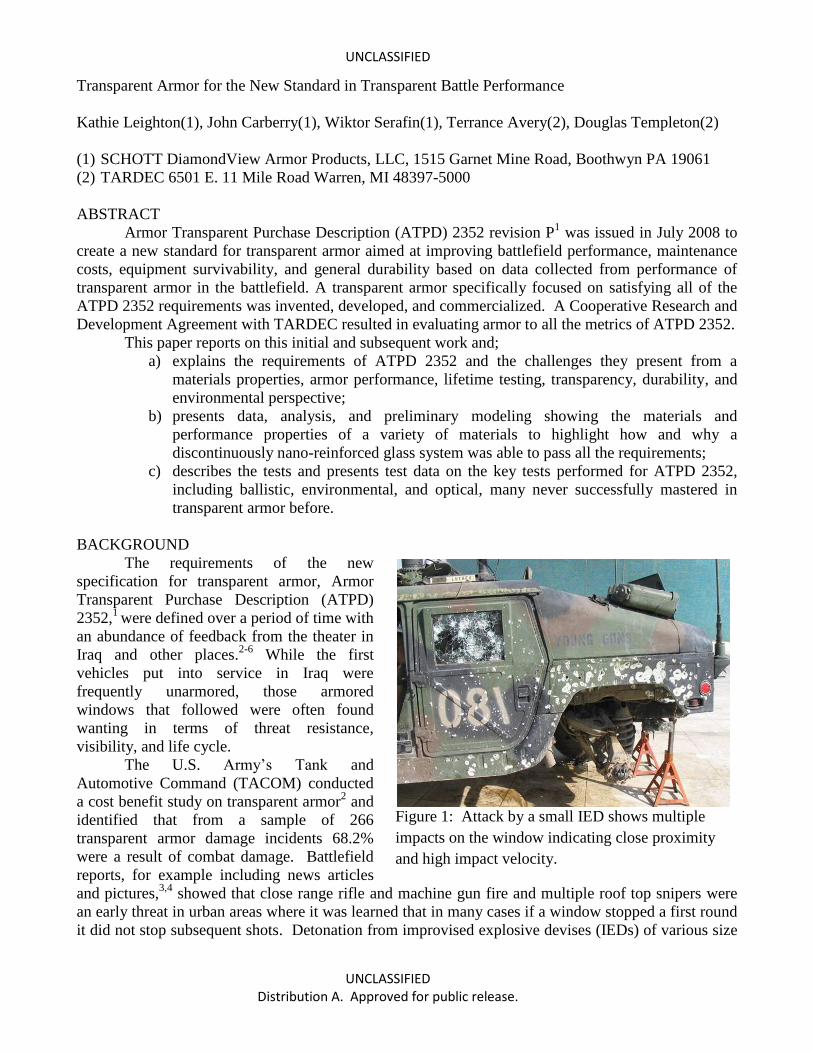
Figure 1: Attack by a small IED shows multiple
impacts on the window indicating close proximity
and high impact velocity.
Report Documentation Page Form ApprovedOMB No. 0704-0188
Public reporting burden for the collection of information is estimated to average 1 hour per response, including the time for reviewing instructions, searching existing data sources, gathering andmaintaining the data needed, and completing and reviewing the collection of information. Send comments regarding this burden estimate or any other aspect of this collection of information,including suggestions for reducing this burden, to Washington Headquarters Services, Directorate for Information Operations and Reports, 1215 Jefferson Davis Highway, Suite 1204, ArlingtonVA 22202-4302. Respondents should be aware that notwithstanding any other provision of law, no person shall be subject to a penalty for failing to comply with a collection of information if itdoes not display a currently valid OMB control number.
1. REPORT DATE 04 JAN 2011
2. REPORT TYPE Technical Document
3. DATES COVERED 06-03-2010 to 27-11-2010
4. TITLE AND SUBTITLE Transparent Armor for the New Standard in Transparent Battle Performance
5a. CONTRACT NUMBER CRADA #08-18
5b. GRANT NUMBER
5c. PROGRAM ELEMENT NUMBER
6. AUTHOR(S) Kathie Leighton; John Carberry; Wiktor Serafin; Terrance Avery;Douglas Templeton
5d. PROJECT NUMBER
5e. TASK NUMBER
5f. WORK UNIT NUMBER
7. PERFORMING ORGANIZATION NAME(S) AND ADDRESS(ES) SCHOTT DiamondView Armor Products, LLC,,1515 Garnet Mine Road,Boothwyn,PA,19061
8. PERFORMING ORGANIZATIONREPORT NUMBER ; #21439
9. SPONSORING/MONITORING AGENCY NAME(S) AND ADDRESS(ES) U.S. Army TARDEC, 6501 East Eleven Mile Rd, Warren, Mi, 48397-5000
10. SPONSOR/MONITOR’S ACRONYM(S) TARDEC
11. SPONSOR/MONITOR’S REPORT NUMBER(S) #21439
12. DISTRIBUTION/AVAILABILITY STATEMENT Approved for public release; distribution unlimited
13. SUPPLEMENTARY NOTES Submitted to American Ceramics Meeting
14. ABSTRACT Armor Transparent Purchase Description (ATPD) 2352 revision P was issued in July 2008 to create a newstandard for transparent armor aimed at improving battlefield performance, maintenance costs,equipment survivability, and general durability based on data collected from performance of transparentarmor in the battlefield. A transparent armor specifically focused on satisfying all of the ATPD 2352requirements was invented, developed, and commercialized. A Cooperative Research and DevelopmentAgreement with TARDEC resulted in evaluating armor to all the metrics of ATPD 2352. This paperreports on this initial and subsequent work and a) explains the requirements of ATPD 2352 and thechallenges they present from a materials properties, armor performance, lifetime testing, transparency,durability, and environmental perspective b) presents data, analysis, and preliminary modeling showingthe materials and performance properties of a variety of materials to highlight how and why adiscontinuously nano-reinforced glass system was able to pass all the requirements c) describes the testsand presents test data on the key tests performed for ATPD 2352, including ballistic, environmental, andoptical, many never successfully mastered in transparent armor before.
15. SUBJECT TERMS
16. SECURITY CLASSIFICATION OF: 17. LIMITATION OF ABSTRACT
Public Release
18. NUMBEROF PAGES
12
19a. NAME OFRESPONSIBLE PERSON
a. REPORT unclassified
b. ABSTRACT unclassified
c. THIS PAGE unclassified

Standard Form 298 (Rev. 8-98) Prescribed by ANSI Std Z39-18
UNCLASSIFIED
UNCLASSIFIED Distribution A. Approved for public release.
were ubiquitous and found to impact windows with high velocity spray of fragments,5,6
for example as
shown in Figure 1.
In addition to battle field threats, the harsh environment imposes strong thermo-mechanical
challenges to transparent armor degrading the polymer layers resulting in delamination, bubbles, loss
of adhesion, clouding and discoloring. Extreme thermal excursions and shocks caused cracking in the
glass and also contributed to delamination. Sand abrading against the armor windows produces
surface defects and surface defects are known to reduce the strength of glass and lead to cracking.7,8
Thermal extremes in Afghanistan have been reported from as low as -46oC (-51
oF) and as high
as 51 o
C (124 o
F), and in Iraq extreme highs in the summer can reach 46 o
C (115 o
F) to 52 o
C (125 o
F)
in the desert areas and have even been reported to 49 o
C (120 o
F) in the mountain valleys.9 Thermal
extremes of the natural environment combine with thermal shocks and contamination associated with
operation and logistics including moving from storage to use, air drops, chemical spray downs, water
exposure in fording, and vehicle road dynamics and vibrations.
This severe thermo-mechanical and contamination prone environment is made even worse by
the degrading power of the sun. NASA Goddard reports data collected by the Solar Radiation and
Climate Experiment10,11
satellites show that the electromagnetic energy of the sun that hits Earth’s
atmosphere varies with solar conditions and is about 1368 W/m2. The insolation, the amount of
electromagnetic energy that impinges the surface of the Earth, is less due to cloud cover and surface
obliquity and varies with elevation, latitude, time of day and season being greatest at high elevations,
tropical latitudes, noon, and in the northern hemisphere summer. The spectrum of insolation also varies
with location on the Earth, and due to the fact the direct irradiance from the sun varies more in
spectrum than in total energy. NASA’s Total Ozone Mapping Spectrometer results
indicate the
majority of the recent battlefield conflicts take place in regions of the World exposed to the most
damaging high energy waves, UV-B in the 290 to 320 nm range.
Replacement and operation needs for transparent armor was running at a cost of $3-$12 million
a month during Fiscal Years 2006 - 2008, with a significant percentage related to replacements due to
the problems above.
In the same time frame, windows that could offer the necessary higher level of protection were
too heavy and too thick. Armor weight strains the mechanical components of a vehicle increasing
wear and fuel consumption; in one study 16% of fuel consumption was directly related to road weight
of a vehicle.12
Reducing the weight of a 4.8 liter V8 diesel engine truck can save 0.3-0.9% in fuel costs
per 100 lbs of weight savings.13
Since windows are mounted high up in a vehicle, transparent armor
weight was also contributing to the problem of mine resistant vehicles rolling over. Armor weight can
slow down transportation to theater and mobility once there.
While life cycle costs are critical and long term budgets require low maintenance costs, the
equipment’s role in mission effectiveness is the primary and first priority and it is unacceptable for the
equipment to fail and compromise a mission. The materials used in many of the first transparent
armors delivered to the field absorbed light in the infrared spectrum (IR) making the use of night
vision goggles, which function in the near infrared, impossible or impractical requiring such high
power levels that glare impaired vision to the point of being useless. The armored window is first a
window, so thick windows with distortion, poor visibility, and lost visibility after impact were a
problem in many cases.
THE ATPD 2352 REQUIREMENTS
The ATPD 2352 specification addressed all these challenges with well defined requirements
related to visible and optical properties in the visible and IR, requiring rifle and fragment penetration
resistance at various levels, and providing requirements to maintain necessary visible and optical
capabilities after exposure to thermal shock, humidity, solar loads, cycles of high temperature, low
UNCLASSIFIED
UNCLASSIFIED Distribution A. Approved for public release.
temperatures relevant to storage, abrasion on strike face and safe side, and chemical exposures on both
sides.
Visible and Optical Requirements
First and foremost a window must offer visibility for situational awareness both in daylight and
at night. In this military setting, night vision is critical to maintain situational awareness in the dark
and the use of night vision goggles (NVG) is not optional. The ATPD 2352 provides requirements and
test protocols for six optical tests.
The first is a visual inspection with defect limitations where, in the most recent version,
Paragraph 4.1.1 Allowable Defects in ATPD 2352 Revision R, the inspection is required to be
performed looking from the inside through the window, a procedural detail that illustrates that most
importantly these are windows to see through and secondly armor.
The next two tests are to measure the transmission of the window in the visible range, luminous
transmission, and then in the near IR for NVG compatibility.
ATPD 2352 paragraph 4.4.1 defines how to measure luminous transmittance, “Luminous
(photopic) transmittance shall be determined in accordance with the photopic transmission
measurement procedure given in MIL-DTL-62420. Transmittance shall be determined before and after
the exposure of the Sun Exposure Weathering test, 4.3.5. Spectral transmittance shall be measured at
wavelength intervals of 10 nm or less over the 400 to 930 nm band at normal incidence. Luminous
visible light transmittance corresponding to daylight vision is determined by integration of individual
photopic transmission values in the 400 to 700 nm range, as discussed in MIL-DTL-62420.”
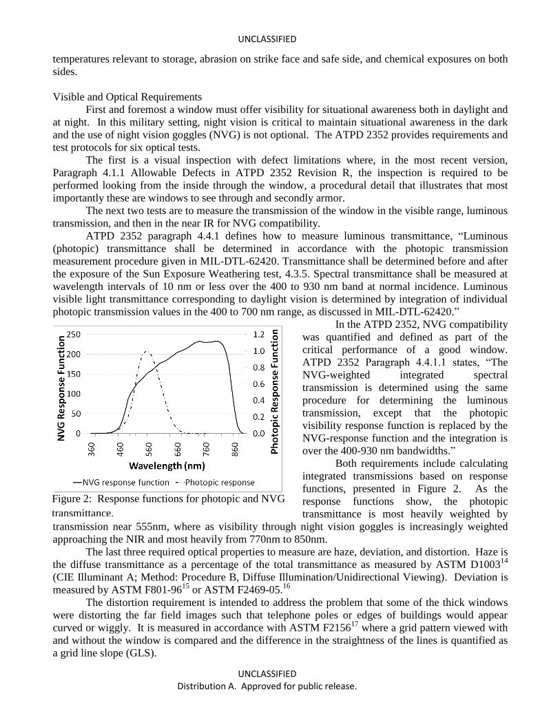
In the ATPD 2352, NVG compatibility
was quantified and defined as part of the
critical performance of a good window.
ATPD 2352 Paragraph 4.4.1.1 states, “The
NVG-weighted integrated spectral
transmission is determined using the same
procedure for determining the luminous
transmission, except that the photopic
visibility response function is replaced by the
NVG-response function and the integration is
over the 400-930 nm bandwidths.”
Both requirements include calculating
integrated transmissions based on response
functions, presented in Figure 2. As the
response functions show, the photopic
transmittance is most heavily weighted by
transmission near 555nm, where as visibility through night vision goggles is increasingly weighted
approaching the NIR and most heavily from 770nm to 850nm.
The last three required optical properties to measure are haze, deviation, and distortion. Haze is
the diffuse transmittance as a percentage of the total transmittance as measured by ASTM D100314
(CIE Illuminant A; Method: Procedure B, Diffuse Illumination/Unidirectional Viewing). Deviation is
measured by ASTM F801-9615
or ASTM F2469-05.16
The distortion requirement is intended to address the problem that some of the thick windows
were distorting the far field images such that telephone poles or edges of buildings would appear
curved or wiggly. It is measured in accordance with ASTM F215617
where a grid pattern viewed with
and without the window is compared and the difference in the straightness of the lines is quantified as
a grid line slope (GLS).
Figure 2: Response functions for photopic and NVG
transmittance.
UNCLASSIFIED
UNCLASSIFIED Distribution A. Approved for public release.
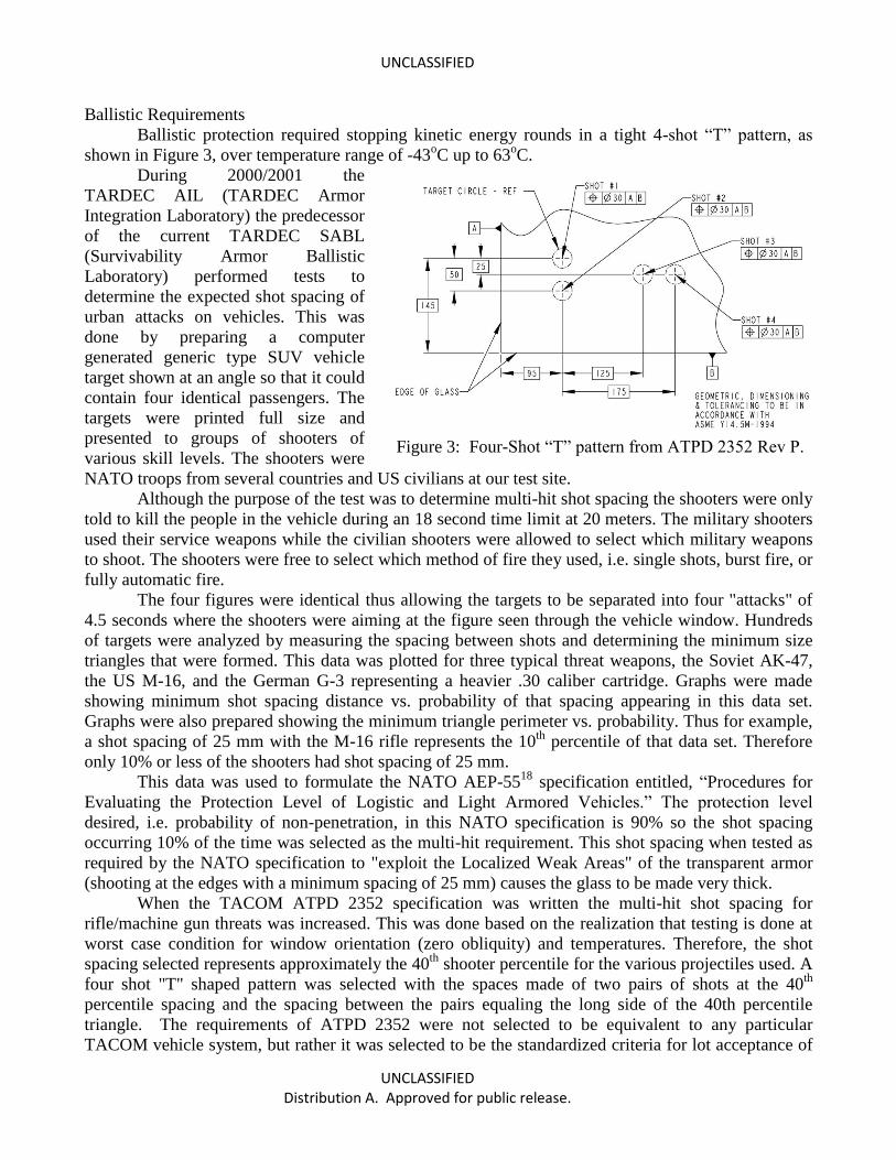
Ballistic Requirements
Ballistic protection required stopping kinetic energy rounds in a tight 4-shot “T” pattern, as
shown in Figure 3, over temperature range of -43oC up to 63
oC.
During 2000/2001 the
TARDEC AIL (TARDEC Armor
Integration Laboratory) the predecessor
of the current TARDEC SABL
(Survivability Armor Ballistic
Laboratory) performed tests to
determine the expected shot spacing of
urban attacks on vehicles. This was
done by preparing a computer
generated generic type SUV vehicle
target shown at an angle so that it could
contain four identical passengers. The
targets were printed full size and
presented to groups of shooters of
various skill levels. The shooters were
NATO troops from several countries and US civilians at our test site.
Although the purpose of the test was to determine multi-hit shot spacing the shooters were only
told to kill the people in the vehicle during an 18 second time limit at 20 meters. The military shooters
used their service weapons while the civilian shooters were allowed to select which military weapons
to shoot. The shooters were free to select which method of fire they used, i.e. single shots, burst fire, or
fully automatic fire.
The four figures were identical thus allowing the targets to be separated into four "attacks" of
4.5 seconds where the shooters were aiming at the figure seen through the vehicle window. Hundreds
of targets were analyzed by measuring the spacing between shots and determining the minimum size
triangles that were formed. This data was plotted for three typical threat weapons, the Soviet AK-47,
the US M-16, and the German G-3 representing a heavier .30 caliber cartridge. Graphs were made
showing minimum shot spacing distance vs. probability of that spacing appearing in this data set.
Graphs were also prepared showing the minimum triangle perimeter vs. probability. Thus for example,
a shot spacing of 25 mm with the M-16 rifle represents the 10th
percentile of that data set. Therefore
only 10% or less of the shooters had shot spacing of 25 mm.
This data was used to formulate the NATO AEP-5518
specification entitled, “Procedures for
Evaluating the Protection Level of Logistic and Light Armored Vehicles.” The protection level
desired, i.e. probability of non-penetration, in this NATO specification is 90% so the shot spacing
occurring 10% of the time was selected as the multi-hit requirement. This shot spacing when tested as
required by the NATO specification to "exploit the Localized Weak Areas" of the transparent armor
(shooting at the edges with a minimum spacing of 25 mm) causes the glass to be made very thick.
When the TACOM ATPD 2352 specification was written the multi-hit shot spacing for
rifle/machine gun threats was increased. This was done based on the realization that testing is done at
worst case condition for window orientation (zero obliquity) and temperatures. Therefore, the shot
spacing selected represents approximately the 40th
shooter percentile for the various projectiles used. A
four shot "T" shaped pattern was selected with the spaces made of two pairs of shots at the 40th
percentile spacing and the spacing between the pairs equaling the long side of the 40th percentile
triangle. The requirements of ATPD 2352 were not selected to be equivalent to any particular
TACOM vehicle system, but rather it was selected to be the standardized criteria for lot acceptance of
Figure 3: Four-Shot “T” pattern from ATPD 2352 Rev P.
UNCLASSIFIED
UNCLASSIFIED Distribution A. Approved for public release.
transparent armor. It is important to remember that "passing" the ATPD 2352 ballistic requirements do
not assure that the product will pass the protection requirements of a particular vehicle system.
Environmental Requirements
Environmental specifications and tests in the ATPD 2352 derive, with some modifications,
from the United States Military Standard referred to as MIL-STD-810, "Department of Defense Test
Method Standard for Environmental Engineering Considerations and Laboratory Tests" which
establish chamber test methods to replicate the effects the environment has on materials and structures
rather than on direct simulation of the environment.19
Two different versions of MIL-STD-810, F and
G, are referenced in the ATPD 2352 presumably because both standards were being modified during
the same time period. Five different tests are required; Low Temperature, High Temperature,
Humidity, Temperature Shock, and Sun exposure weathering. De-icing requirements and tests also
test response to thermal stresses. After each test the part is returned to room temperature and ambient
conditions and inspected to the six optical, including visual, requirements discussed above, and held to
the standards of the original optical requirements.
The low temperature cycle includes a 24 hour hold at -54oC in accordance with MIL-STD-810F
Method 502.4 Procedure I. This method was developed to replicate material failures that can occur
during low temperature storage of military equipment, Specific failures identified by MIL-STD-810
that are relevant to transparent armor are; hardening and embrittling of polymers leading to cracking
and crazing, reduced impact strength, static failure of restrained glass, and condensation and freezing
of water. This procedure is intended to test materials in storage conditions and prepare them for
additional testing to ensure they meet operating requirements after storage, which in the case of the
ATPD 2352 includes the visual inspection and optical tests above.
The high temperature test is in accordance with MIL-STD-810G Method 501.5, Procedure I,
A2, Induced. It includes a 24 hour heating and cooling cycle where the chamber varies between 30
and 63oC. The relative humidity is varied from 44% to 5% with the lowest levels at the highest
temperatures. Three cycles are required. Failures listed by MIL-STD-810 that can occur under high
temperature and relevant to transparent armor include discoloration, cracking or crazing of organic
materials, out gassing, and binding due to differential expansion of material with dissimilar
coefficients of thermal expansion (CTE). This test is limited to use to evaluate the effects of short
term, even distributions of heat without synergistic effects. Procedure I is applicable to storage
conditions where the parts are protected from the added heat, +19oC (35
oF),
19,20 and synergistic
radiation damage that can be generated by the sun. Its effect on window operation is evaluated by post
test visual and optical measurements.
Conformance to optical properties after exposure to warm humid environs is evaluated by
exposing windows to five modified cycles of the aggravated humidity profile shown in MIL-STD-
810G, Figure 507.5-7. The modified cycle is 48 hours duration at 95% relative humidity and each
cycle includes a 30 hr hold at 60oC, and an 8 hr hold at 30
oC. After the test, the sample is conditioned
at 23°C ± 10°C and 50% maximum relative humidity for 48 hours then inspected to ensure no
indication of moisture buildup, bond separation, or any other forms of image degradation per the
allowable defects specification. The sample returns to normal ambient conditions and is inspected to
the visual and optical specifications.
Temperature shock effects on the transparent armor are evaluated using Method 503.5,
Procedure I-C of MIL-STD-810 adapted to include an 18 hour period at -30°C followed by an 18 hour
period at +60°C with a transfer time of not more than five minutes. At the conclusion of the thermal
shock test the sample is required to conform to the visual and optical requirements. MIL-STD-810
suggests the use of this test when material is likely to experience sudden changes in temperature such
as during transfer from climate controlled storage or enclosure to hotter or colder outside temperatures,
UNCLASSIFIED
UNCLASSIFIED Distribution A. Approved for public release.
or when ascending to high altitudes from a high temperature ground environment, or vice a versus such
as in an air drop. It is not intended to test for conditions such as water hitting a hot surface or rapid
localized heating of a cold surface. Transparent armor exposed to this test may experience shattering
of glass, differential contraction or expansion rates or induced strain rates from dissimilar materials,
deformation or fracture of components, cracking of surface coatings.
De-icing specifications in the ATPD 2352 require de-icing at -25oC in 60 minutes. A window
is cooled to -25oC and held for 12 hours then sprayed with water from a 345kPa pressure gun. The
water is allowed to form into ice for 25 minutes before the de-icer is turned on. This ATPD 2352
specified test imposes a combination of thermal stresses and the window is required to be inspected for
visual and optical requirements after the test.
Sun exposure weathering tests require the use of Procedure II in MIL-STD-810 Method 505.
This procedure was developed to include both the temperature and actinic effects of solar loads. The
specified cycle is 20 out of 24 hours at 1120W/m2 at a constant temperature of 49
oC. For four hours
each cycle the lights are turned off to induce alternating thermal stressing and allow “dark” processes
to occur. The most intense naturally occurring total irradiance on the earth at sea level is represented
by the irradiance cycles of Procedure I, which only reach 1120W/m2 for 2 hours out of each 24 hours.
Procedure II accelerates the amount of total irradiance impinging the sample by 2.5 times requiring the
1120W/m2 for 20 of the 24 hours. In addition, Procedure II requires the use of full sun spectrum
lamps with 68.3% of the spectrum comprising the high energy UV wavelengths below 400nm so are
more active in evaluating actinic material responses which show up in yellowing, discoloration,
cracking, or, in extreme cases, mechanical degradation. The acceleration of these actinic processes
may be much more than 2.5 times due to the added UV content and require correlation with natural
processes and conditions to quantify.
GLASS-CERAMICS TO MEET ATPD 2352
The emerging requirements of APTD 2352 dictate new and critical properties the components
and window systems should have:
i) Opaqueness in the ultra-violet (UV), below 370 nanometers to protect the polymer
constituents from solar radiation;
ii) Good transparency between 400 and 1200 nanometers for human and night vision visibility;
iii) Very low or no coefficient of thermal expansion (CTE) to promote resistance to thermal
shock and cycling;
iv) Unique failure mechanisms to promote multi-shot performance at low weight;
v) Superior ballistic performance to promote low weight against IED fragments.
Glasses used in armor are primarily soda-lime-silicate, which can be improved for infra-red
(IR) transmission if made with very low iron and borosilicate glass which has a low density and low
CTE. Both offer good transparency in the visible range, but are transparent in the UV (see Table I).
Table I: Properties of soda-lime-silicate and borosilicate glass compared to glass-ceramics.
Material Density
(g/cc)
CTE (ppm) Transmission
at 370 nm
Young’s
Modulus (GPa)
Soda-Lime 2.4920
9.0321
>50%21
73.120
Borosilicate 2.2220
3.2522
>85%23
63.120
LAS Glass-Ceramic 2.5625
0 +/- 0.324
0 24, 27
9225
Evaluation of commercially available glass-ceramics, focusing on large production of glass-
ceramics available in the lithium alumino silicate, Li2-Al2O3-SiO2 (LAS) family, often used in fire
places and cook tops and other appliances, reveals several advantages of this material.24, 25, 26
UNCLASSIFIED
UNCLASSIFIED Distribution A. Approved for public release.
The CTE is 0.3 parts per million but is balanced between the LAS crystal having a negative
CTE and the glass a positive CTE.
The glass-ceramic is filled about 65% by volume with nano-crystals of about 70 nanometers
and smaller size. This offers the unique advantage that it blocks all wave lengths less than four times
this size, but allows the higher wavelength visible light to pass. Properties are listed in Table I.
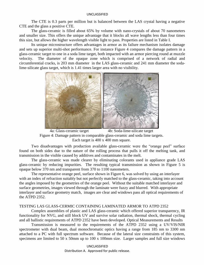
Its unique microstructure offers advantages in armor as its failure mechanism isolates damage
and sets up superior multi-shot performance. For instance Figure 4 compares the damage pattern in a
glass-ceramic target to one in a soda lime target, both impacted with an armor piercing round at muzzle
velocity. The diameter of the opaque zone which is comprised of a network of radial and
circumferential cracks, is 203 mm diameter in the LAS glass-ceramic and 241 mm diameter the soda-
lime-silicate glass target, which is 1.41 times larger area with no visibility.
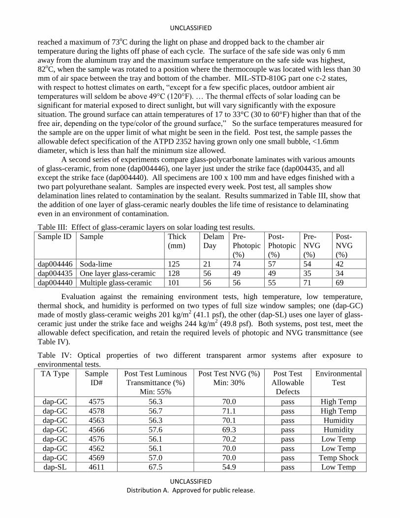
Two disadvantages with production available glass-ceramic were the “orange peel” surface
found on both sides due to the nature of the rolling process that pulls it off the melting tank, and
transmission in the visible caused by additives and contaminates in the melt.
The glass-ceramic was made clearer by eliminating colorants used in appliance grade LAS
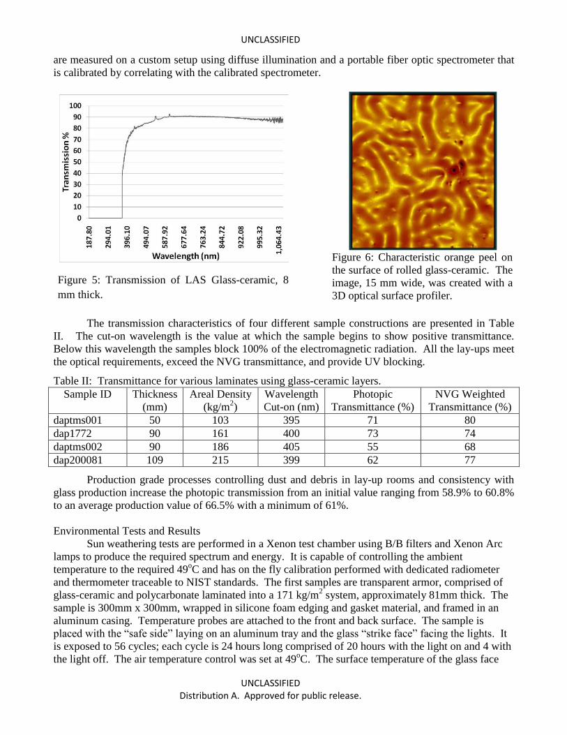
glass-ceramic by reducing impurities. The resulting typical transmission as shown in Figure 5 is
opaque below 370 nm and transparent from 370 to 1100 nanometers.
The representative orange peel, surface shown in Figure 6, was solved by using an interlayer
with an index of refraction suitably but not perfectly matched to the glass-ceramic, taking into account
the angles imposed by the geometries of the orange peel. Without the suitable matched interlayer and
surface geometries, images viewed through the laminate were fuzzy and blurred. With appropriate
interlayer and surface geometry match, images are clear and windows pass all optical requirements of
the ATPD 2352.
TESTING LAS GLASS-CERMIC CONTAINING LAMINATED ARMOR TO ATPD 2352
Complex assemblies of plastic and LAS glass-ceramic which offered superior transparency, IR
functionality for NVG, and still block UV and survive solar radiation, thermal shock, thermal cycling
and all ballistic requirements of ATPD 2352 have been developed. Optical Measurements and Results
Transmission is measured to the requirements of the ATPD 2352 using a UV/VIS/NIR
spectrometer with dual beam, dual monochromatic optics having a range from 185 nm to 3300 nm
attached to a PC with full spectrum software. Because of the lateral size constraints of this system,
specimens are limited to 50 x 50mm up to 100 x 100mm size. Larger samples and full size windows
4a: Glass-ceramic target 4b: Soda-lime-silicate target
Figure 4: Damage pattern in comparable glass-ceramic and soda lime targets.
Each target is 400 x 400 mm square.
UNCLASSIFIED
UNCLASSIFIED Distribution A. Approved for public release.
are measured on a custom setup using diffuse illumination and a portable fiber optic spectrometer that
is calibrated by correlating with the calibrated spectrometer.
The transmission characteristics of four different sample constructions are presented in Table
II. The cut-on wavelength is the value at which the sample begins to show positive transmittance.
Below this wavelength the samples block 100% of the electromagnetic radiation. All the lay-ups meet
the optical requirements, exceed the NVG transmittance, and provide UV blocking.
Table II: Transmittance for various laminates using glass-ceramic layers.
Sample ID Thickness
(mm)
Areal Density
(kg/m2)
Wavelength
Cut-on (nm)
Photopic
Transmittance (%)
NVG Weighted
Transmittance (%)
daptms001 50 103 395 71 80
dap1772 90 161 400 73 74
daptms002 90 186 405 55 68
dap200081 109 215 399 62 77
Production grade processes controlling dust and debris in lay-up rooms and consistency with
glass production increase the photopic transmission from an initial value ranging from 58.9% to 60.8%
to an average production value of 66.5% with a minimum of 61%.
Environmental Tests and Results
Sun weathering tests are performed in a Xenon test chamber using B/B filters and Xenon Arc
lamps to produce the required spectrum and energy. It is capable of controlling the ambient
temperature to the required 49oC and has on the fly calibration performed with dedicated radiometer
and thermometer traceable to NIST standards. The first samples are transparent armor, comprised of
glass-ceramic and polycarbonate laminated into a 171 kg/m2 system, approximately 81mm thick. The
sample is 300mm x 300mm, wrapped in silicone foam edging and gasket material, and framed in an
aluminum casing. Temperature probes are attached to the front and back surface. The sample is
placed with the “safe side” laying on an aluminum tray and the glass “strike face” facing the lights. It
is exposed to 56 cycles; each cycle is 24 hours long comprised of 20 hours with the light on and 4 with
the light off. The air temperature control was set at 49oC. The surface temperature of the glass face
Figure 5: Transmission of LAS Glass-ceramic, 8
mm thick.
Figure 6: Characteristic orange peel on
the surface of rolled glass-ceramic. The
image, 15 mm wide, was created with a
3D optical surface profiler.
UNCLASSIFIED
UNCLASSIFIED Distribution A. Approved for public release.
reached a maximum of 73oC during the light on phase and dropped back to the chamber air
temperature during the lights off phase of each cycle. The surface of the safe side was only 6 mm
away from the aluminum tray and the maximum surface temperature on the safe side was highest,
82oC, when the sample was rotated to a position where the thermocouple was located with less than 30
mm of air space between the tray and bottom of the chamber. MIL-STD-810G part one c-2 states,
with respect to hottest climates on earth, “except for a few specific places, outdoor ambient air
temperatures will seldom be above 49°C (120°F). … The thermal effects of solar loading can be
significant for material exposed to direct sunlight, but will vary significantly with the exposure
situation. The ground surface can attain temperatures of 17 to 33°C (30 to 60°F) higher than that of the
free air, depending on the type/color of the ground surface,” So the surface temperatures measured for
the sample are on the upper limit of what might be seen in the field. Post test, the sample passes the
allowable defect specification of the ATPD 2352 having grown only one small bubble, <1.6mm
diameter, which is less than half the minimum size allowed.
A second series of experiments compare glass-polycarbonate laminates with various amounts
of glass-ceramic, from none (dap004446), one layer just under the strike face (dap004435, and all
except the strike face (dap004440). All specimens are 100 x 100 mm and have edges finished with a
two part polyurethane sealant. Samples are inspected every week. Post test, all samples show
delamination lines related to contamination by the sealant. Results summarized in Table III, show that
the addition of one layer of glass-ceramic nearly doubles the life time of resistance to delaminating
even in an environment of contamination.
Table III: Effect of glass-ceramic layers on solar loading test results.
Sample ID Sample Thick
(mm)
Delam
Day
Pre-
Photopic
(%)
Post-
Photopic
(%)
Pre-
NVG
(%)
Post-
NVG
(%)
dap004446 Soda-lime 125 21 74 57 54 42
dap004435 One layer glass-ceramic 128 56 49 49 35 34
dap004440 Multiple glass-ceramic 101 56 56 55 71 69
Evaluation against the remaining environment tests, high temperature, low temperature,
thermal shock, and humidity is performed on two types of full size window samples; one (dap-GC)
made of mostly glass-ceramic weighs 201 kg/m2 (41.1 psf), the other (dap-SL) uses one layer of glass-
ceramic just under the strike face and weighs 244 kg/m2 (49.8 psf). Both systems, post test, meet the
allowable defect specification, and retain the required levels of photopic and NVG transmittance (see
Table IV).
Table IV: Optical properties of two different transparent armor systems after exposure to
environmental tests.
TA Type Sample
ID#
Post Test Luminous
Transmittance (%)
Min: 55%
Post Test NVG (%)
Min: 30%
Post Test
Allowable
Defects
Environmental
Test
dap-GC 4575 56.3 70.0 pass High Temp
dap-GC 4578 56.7 71.1 pass High Temp
dap-GC 4563 56.3 70.1 pass Humidity
dap-GC 4566 57.6 69.3 pass Humidity
dap-GC 4576 56.1 70.2 pass Low Temp
dap-GC 4562 56.1 70.0 pass Low Temp
dap-GC 4569 57.0 70.0 pass Temp Shock
dap-SL 4611 67.5 54.9 pass Low Temp
UNCLASSIFIED
UNCLASSIFIED Distribution A. Approved for public release.
dap-SL 4615 67.0 54.4 pass Low Temp
dap-SL 4616 65.8 56.3 pass Temp Shock
dap-SL 4617 67.2 55.0 pass Temp Shock
dap-SL 4618 67.9 55.8 pass Humidity
dap-SL 4622 66.8 55.8 pass Humidity
dap-SL 4628 66.7 54.4 pass High Temp
dap-SL 4625 68.7 56.6 pass High Temp
BALLISTIC PERFORMANCE
Ballistic weight efficiencies of the developed LAS glass-ceramic containing transparent armor
recipes are typically 20% - 50% lighter than incumbent soda-lime based transparent armor depending
on the specific threats of interest. Examples are listed in Table V.
Table V. Ballistic performance of various LAS glass-ceramic based armor recipes
Sample #
Areal
Density
(kg/m2
(psf))
Thickness
(mm) Projectile
Impact
Velocity
Range (m/s) Multi-hit
Test
Temp
1829 255 (52) 168 7.62 x 51 AP M993 968 981 4-shot T 65 oC
8092B 255 (52) 114 7.62 x 51 AP M993 966 977 4-shot T -43 oC
8068L 254 (52) 114 7.62 x 51 AP M993 962 973 4-shot T Ambient
ddm1226 231 (47) 107 20mm FSP 1509 1522
3-shot 160 mm
Triangle Ambient
ddm1827 202 (41) 142 0.30 Cal AP-M2 877 882 4-ahot T 65 oC
ddm1031 188 (38) 89 0.30 Cal AP-M2 875 889 4-shot T Ambient
ddm0983 169 (35) 82 20mm FSP 1054 1080
3 shots 150 mm
triangle Ambient
ddm0971 168 (34) 79 7.62 x 54R API 884 895
3 shots 120mm
triangle Ambient
ddm0947 173 (35) 83 7.62 x 54R LPS Ball 871 878 4-shot T Ambient
ddm0923 103 (21) 51 7.62 x 51 M80 Ball 831 853
5-shot NIJ
0108.01 III Ambient
ddm0944 103 (21) 48 7.62 x 39 PS Ball 724 729 4-shot T Ambient
ddm0925 103 (21) 51 0.50 Cal FSP 1226
1-shot Ambient
ddm0926 103 (21) 55 0.30 Cal AP-M2 844
1-shot Ambient
ddm0927 103 (21) 48 7.62 x 51 M61 AP 836
1-shot Ambient
ddm1012 95 (19) 43 0.30 Cal AP-M2 872
1-shot Ambient
ddm1470 84 (17) 42 7.62 x 51 M61 AP 781 794 2-shot in 12" Ambient
ddm1472 66 (14) 35 7.62 x 51 M80 Ball 826 837
3-shot 120mm
triangle Ambient
p39 60 (12) 34 0.50 FSP V50 = 1089
Ambient
ddm696 60 (12) 33 7.62 x 51 M80 Ball 888
1-shot, UL 752
level 5 Ambient
ddm693 60 (12) 33 7.62 x 51 M80 Ball 859
1-shot, UL 752
level 5 Ambient
ddm752 60 (12) 33 5.56 x 45 M855 908 919
3 shots in 8"
dia. circle, SD- Ambient
UNCLASSIFIED
UNCLASSIFIED Distribution A. Approved for public release.
STD-01.01
hat-4D 54 (11) 27 12.7 mm AP @ 60o 496
1-shot Ambient
hat-5c 39 (8) 21 7.62 AP @ 60o 773
1-shot Ambient
CONCLUSIONS
An LAS glass-ceramic based transparent armor was developed which is the lightest weight
transparent armor recipe to date that is ballistically qualified to the 3a all temperature level of the
ATDP 2352. In addition, it is capable of passing all other requirements of ATPD 2352 Rev R
weighing 201 kg/m2 (41.1 psf).
ACKNOWLEDGEMENTS
The authors appreciate the support of TARDEC under CRADA #08-18, the funding from the
Technical Support Working Group through EMRTC that supported the environmental test on the full
size windows, and the extensive funding and contributions of materials and the transparent armor
inventions from DiamondView Armor Products (DAP) and then SCHOTT DiamondView Armor
Products which acquired DAP. We acknowledge and appreciate the numerous discussions with
TARDEC staff working to develop the ATPD 2352 purchase description including David Hanson,
David Sass, Steve Hoffman and Robert Goedert who also provided luminous and NVG transmittance
calculation templates. The authors recognize and appreciate that the optical measuring equipment and
techniques were developed and exercised by optical experts at SCHOTT’s R&D facility in Duryea PA,
Carsten Weinhold, David Badack, Joe Granko, and Beth Gober-Mangan. The authors are indebted to
Edgar Aleshire who made numerous contributions to the designs and fabrication of the many test
coupons and to developing production grade processes for improved quality. The authors are grateful
to Rebecca Neill for overseeing tests performed at Dayton T. Brown and for helpful suggestions in
editing the manuscript. Authors acknowledge Zygo Corporation for making the surface profile
measurements shown in Figure 6 free of charge and Tim Talladay for photographs in Figure 4.
REFERENCES
1. “Purchase Specification Transparent Armor ATPD 2352”, TACOM-LCMC, Department of the
Army, [email protected]. Rev P 7 July 2008, Rev R 26 April 2010.
2. David Holm, Raymond Kleinberg, Lisa Prokurat Franks, “Transparent Armor Cost Benefit
Study Fleet Update”, TACOM Cost & Systems Analysis Directorate and RDECOM,
TARDEC, August 2007.
3. “Assassination Rocks Mideast U.S. Strategy”, Combined Wire Services, The Hartford Courant,
22 Nov. 2006.
4. David Swanson, Picture of multi-hit impacts on front windshield of HMMWV, Knight Ridder-
Tribune, front page Detroit Free Press, 7 April 2004.
5. Joshua Partlow, “One Month Two Brushes With Death - In Iraq Lucky is Difficult to Define”,
Washington Post Foreign Service, 23 July 2007.
6. Meg Jones, “Saved by 4” Thick Glass”, Journal Sentinel Online, 13 June 2005.
7. A.M. Muller and D.J. Green, “Elastic Indentation Response of Float Glass Surfaces”, J. Am.
Cer. Soc. 93, [1] 209-216, (2010).
8. A. A. Wereszczak, T. P. Kirkland, M. E. Ragan, K. T. Strong, Jr., H-T Lin, P. Patel “Size
Scaling of Tensile Failure Stress in a Float Soda–Lime–Silicate Glass”, International Journal of
Applied Glass Science 1 [2] 143–150 (2010).
9. “Climatology for Southwest Asia”, http://www.ncdc.noaa.gov/oa/climate/afghan/#intro, joint
web site by National Climatic Data Center, Air Force Combat Climatology Center, and the
Navy hosted by National Oceanic and Atmospheric Administration, Ashville NC 28801.
UNCLASSIFIED
UNCLASSIFIED Distribution A. Approved for public release.
10. “Solar Radiation and Climate Experiment”, http://earthobservatory.nasa.gov/Features/SORCE/,
Earth Observatory, NASA Goddard, updated 18 Dec 2010.
11. R. F. Cahalan, G. Wen, J. W. Harder, and P. Pilewskie, “Temperature responses to spectral
solar variability on decadal time scales”, Geophysical Research Letters, Vol. 37 (2010).
12. N. Lutsey, “Review of technical literature and trends related to automobile mass-reduction
technology”, Institute of Transportation Studies, University of California - Davis. UCD-ITS-
RR-10-10, http://pubs.its.ucdavis.edu/publication_detail.php?id=1390, (2010).
13. A. Casadei and R. Broda, “Impact of Vehicle Weight Reduction on Fuel Economy for Various
Vehicle Architectures”, Project FB769, ©Riccardo Inc. 20 Dec 2007.
14. “Standard Test Method for Haze and Luminous Transmittance of Transparent Plastics,” ASTM
D1003.
15. “Standard Test Method for Measuring Optical Angular Deviation of Transparent Parts,” ASTM
F801-96.
16. “Standard Test Method for Measuring Optical Angular Deviation of Transparent Parts Using
the Double-Exposure Method,” ASTM F2469-05.
17. “Standard Test Method for Measuring Optical Distortion in Transparent Parts Using Grid Line
Slope,” ASTM F2156.
18. “Procedures for Evaluating the Protection Level of Logistic and Light Armored Vehicles”,
AEP-55 Vol. 1 & 2, NATO/PfP unclassified publication, Edition 1, February 2005.
19. “Environmental Engineering Considerations and Laboratory Tests”, Mil-STD-810F (1/1/2000)
and G (10/31/2008).
20. A. A. Wereszczak, K. E. Johanns, T. P. Kirkland, C. E. Anderson, Jr., T. Behner, P. Patel, D.
W. Templeton, ” Strength and Contact Damage Responses in a Soda-Lime-Silicate and a
Borosilicate Glass”, 25th
Army Science Conference, Orlando FL (2006).
21. PPG Starphire® mechanical properties listed on Precision Glass and Optics web site:
http://www.pgo.com/pdf/ppg_starphire.pdf. 22. Borofloat® 33, thermal properties listed on SCHOTT web site:
http://www.us.schott.com/borofloat/english/attribute/thermic/index.html. 23. Borofloat® 33, UV transmission, listed on SCHOTT web site:
http://www.us.schott.com/borofloat/english/attribute/optical/index.html. 24. H. Schiedler, E. Rodek, “Li2O-Al2O3-SiO2 Glass-ceramics”, Ceramic Bulletin, 68 [11] 1926-
1930 (1989).
25. M. Hiltl, H. Nahme, “Dynamic Behavior of a Shock-Loaded Glass-ceramic based on the Li2O-
Al2O3-SiO2 System,” J. Phys. IV France 7, 587-592 (1997).
26. Robax® glass-ceramic properties, listed on MatWeb web site: http://www.matweb.com.
27. W.E. Pannhorst, “Low expansion glass-ceramics: review of the glass-ceramics Ceran® and
Zerodur® and their applications.” In Ceramic Transactions Nucleation and Crystallization in
Liquids and Glasses, edited by M.C. Weinberg, The American Ceramic Society, Ohio Vol. 30,
267 – 276 (1993).