uml diagrams: sequence diagrams the requirements model ... · uml diagrams: sequence diagrams the...
TRANSCRIPT
UML Diagrams:
Sequence Diagrams
The Requirements Model, and
The Dynamic Analysis Model
Prof. Hany H. Ammar, CSEE, WVU, and
Dept. of Computer Science, Faculty of Computers and Information, Cairo University
Outline
• The Requirements Model and the Analysis model
• Importance of Sequence Diagrams
• Rules of sequence diagrams
• Use Cases and Sequence Diagrams
• The System Sequence Diagrams
• The Vending Machine Example
• Other Examples
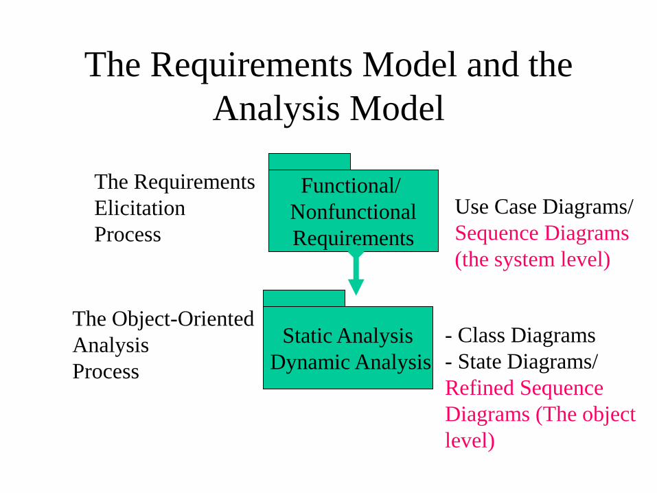
The Requirements Model and the
Analysis Model
Static Analysis
Dynamic Analysis
Functional/
Nonfunctional
Requirements
Use Case Diagrams/
Sequence Diagrams
(the system level)
- Class Diagrams
- State Diagrams/
Refined Sequence
Diagrams (The object
level)
The Requirements
Elicitation
Process
The Object-Oriented
Analysis
Process
Importance of Sequence Diagrams
• Depict object interactions in a given
scenario identified for a given Use Case
• Specify the messages passed between
objects using horizontal arrows including
messages to/from external actors
• Time increases from Top to bottom
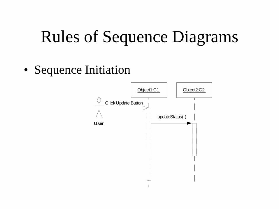
Rules of Sequence Diagrams
• Sequence Initiation
updateStatus( )
Click Update Button
User
Object1:C1 Object2:C2
Rules of Sequence Diagrams
• Identify objects needed to support use case,
determine sequence of internal events
following the external initiating event
• Diagrams that are not initiated with an external
actor represent only a partial sequence
• Partial sequence diagrams should clearly identify
the actor initiated sequence diagrams from which
they are launched
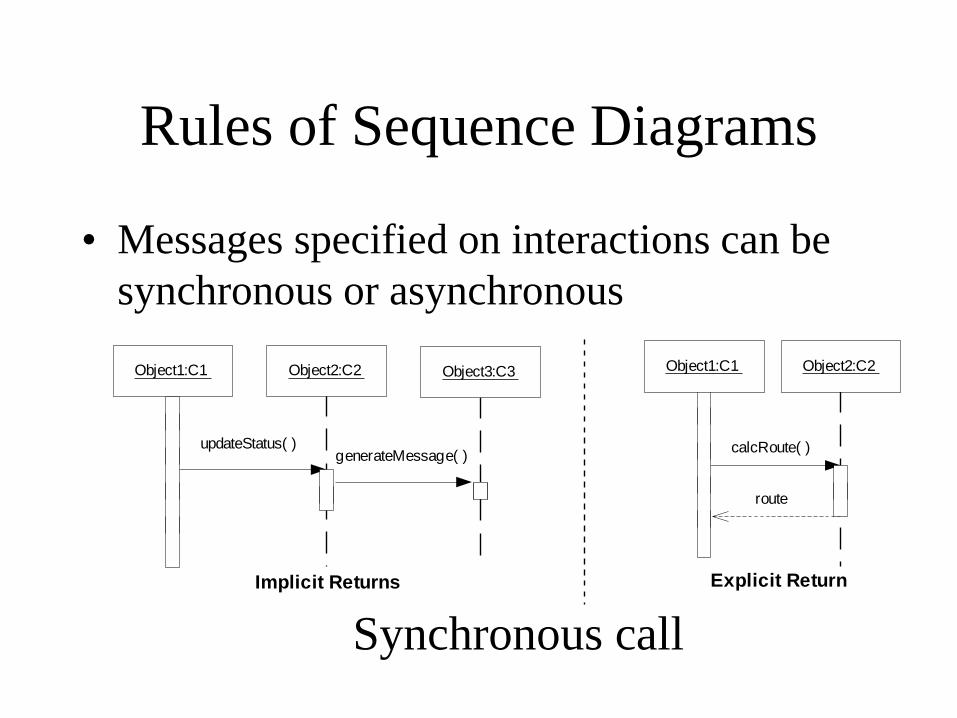
Rules of Sequence Diagrams
• Messages specified on interactions can be
synchronous or asynchronous
updateStatus( )
Object1:C1 Object2:C2
calcRoute( )
route
Object1:C1 Object2:C2
Implicit Returns Explicit Return
Object3:C3
generateMessage( )
Synchronous call
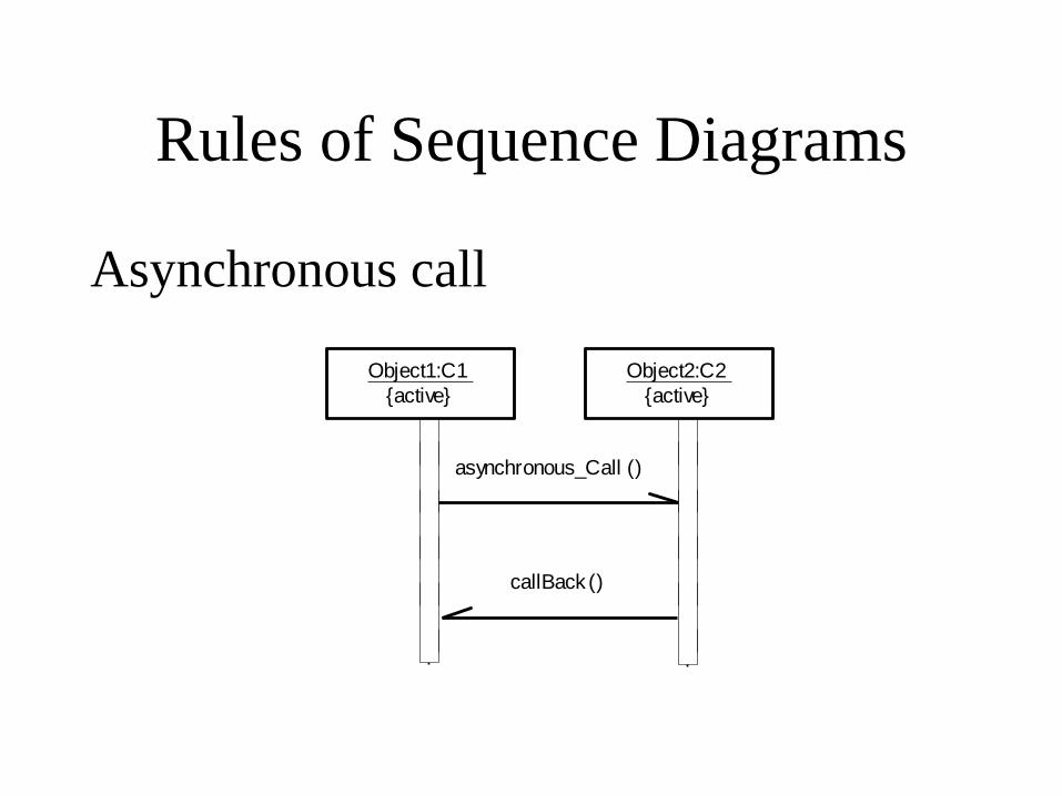
Rules of Sequence Diagrams
Asynchronous call
asynchronous_Call ()
callBack ()
Object1:C1
{active}
Object2:C2
{active}
Rules of Sequence Diagrams
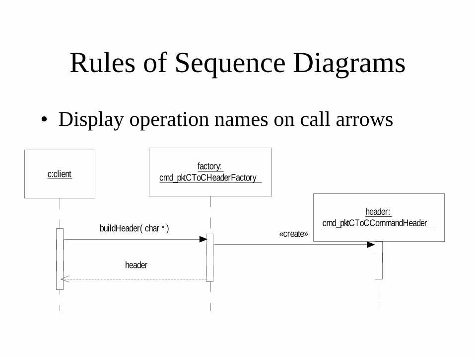
• Display operation names on call arrows
c:clientfactory:
cmd_pktCToCHeaderFactory
header:
cmd_pktCToCCommandHeaderbuildHeader( char * )
«create»
header
Rules of Sequence Diagrams
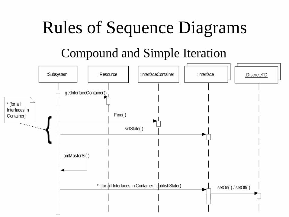
Compound and Simple Iteration
* [for all
Interfaces in
Container] Find( )
amMasterSI( )
setState( )
getInterfaceContainer()
* [for all Interfaces in Container] publishState() setOn( ) / setOff( )
{
:DiscreteFD:DiscreteFD
:Interface:Interface:InterfaceContainer:Subsystem :Resource
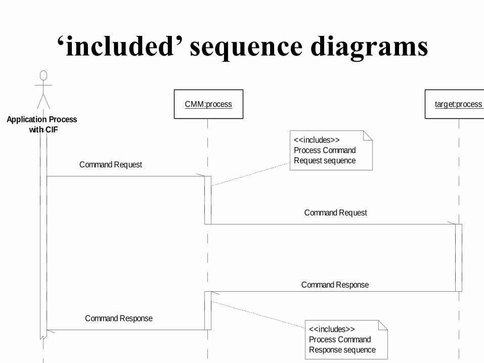
‘included’ sequence diagrams
Command Response
Command Request
Command Request
Command Response
<<includes>>
Process Command
Response sequence
<<includes>>
Process Command
Request sequence
Application Process
with CIF
CMM:process target:process
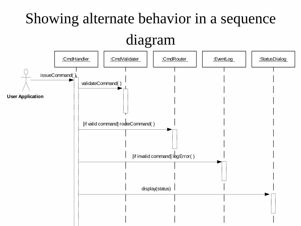
Showing alternate behavior in a sequence
diagram
validateCommand( )
issueCommand( )
User Application
[if valid command] routeCommand( )
[if invalid command] logError( )
display(status)
:CmdHandler :CmdValidater :CmdRouter :EventLog :StatusDialog
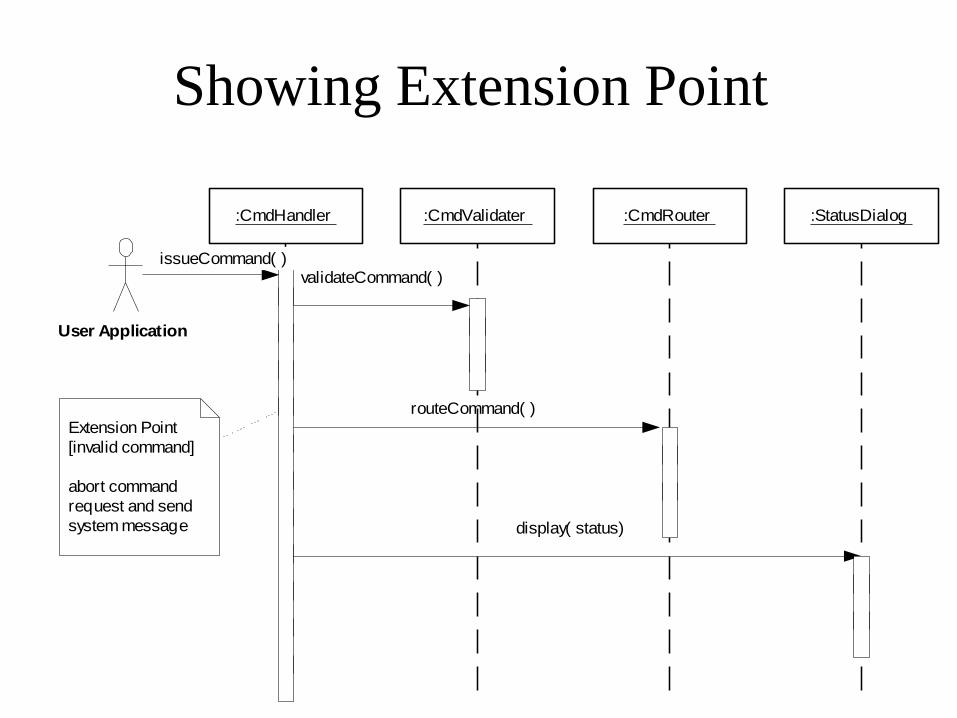
Showing Extension Point
validateCommand( )
routeCommand( )
display( status)
Extension Point
[invalid command]
abort command
request and send
system message
:StatusDialog:CmdRouter:CmdValidater:CmdHandler
issueCommand( )
User Application
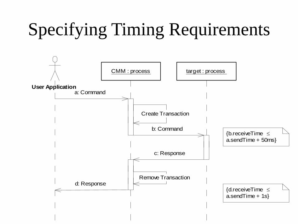
Specifying Timing Requirements
a: Command
Create Transaction
b: Command
d: ResponseRemove Transaction
c: Response
CMM : process target : process
User Application
{b.receiveTime
a.sendTime + 50ms}
{d.receiveTime
a.sendTime + 1s}
Requirements Elicitation Process
Step 4. Refining Use Cases using
System Sequence Diagrams
• System sequence diagrams establish the dynamic behavior in terms of key scenarios of the system for each use case
• The system sequence diagram models a scenario of the system interactions with the environment for a given use case
• Input/output events are clearly identified in each sequence diagram,
• The State of the system before and after each event are also depicted
• Different diagrams model scenarios with the normal flow of events and the abnormal flow of events
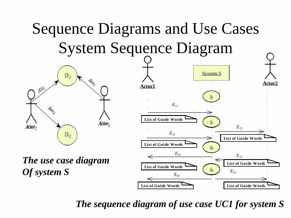
Sequence Diagrams and Use Cases
System Sequence Diagram
The sequence diagram of use case UC1 for system S
Actor1Actor2
System: S
S1
S2
S3
S4
E11
List of Guide Words
List of Guide Words
List of Guide Words
List of Guide Words
List of Guide Words
E21
E12
E22
E32E41
E31
List of Guide Words
List of Guide Words
The use case diagram
Of system S
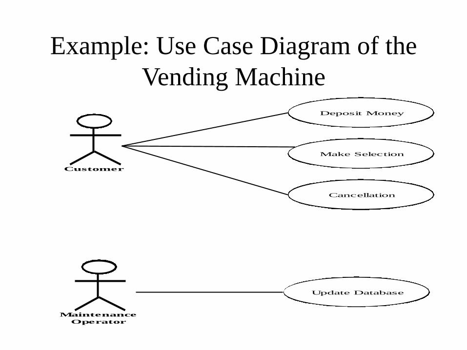
Example: Use Case Diagram of the
Vending Machine
Customer
Deposit Money
Make Selection
Maintenance
Operator
Update Database
Cancellation
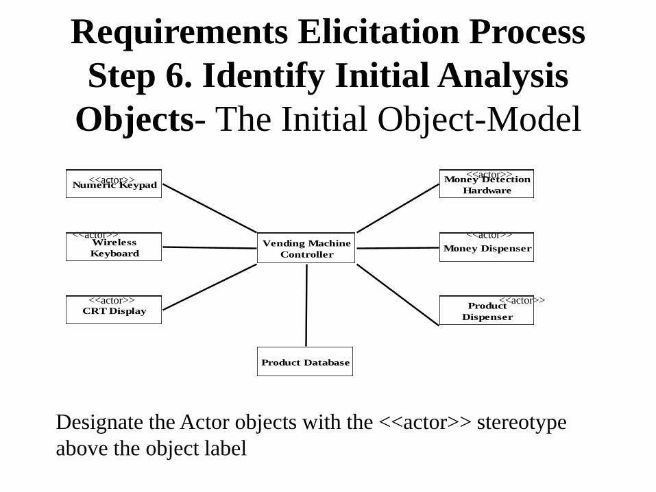
Requirements Elicitation Process
Step 6. Identify Initial Analysis
Objects- The Initial Object-Model
Vending Machine
Controller
Numeric Keypad
Wireless
Keyboard
CRT Display
Money Detection
Hardware
Money Dispenser
Product
Dispenser
Product Database
Designate the Actor objects with the <<actor>> stereotype
above the object label
<<actor>>
<<actor>>
<<actor>>
<<actor>>
<<actor>>
<<actor>>

System Sequence Diagram
for Deposit Money Use Case
Customer
Money Detection
HardwareCRT Display
Vending Machine
Controller
Deposit Money
[Idle State]
Display Welcome
Message
Display Amount
Send Amount
Prompt for Selection
Start Timer
[If Timer > 30 seconds and Invalid or No Selection]
Return Money
Money
Dispenser
Stop
Timer[Idle State]
Display Welcome
Message
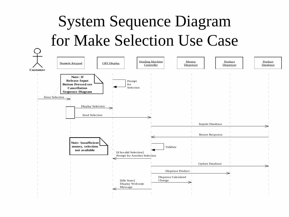
System Sequence Diagram
for Make Selection Use Case
Customer
Numeric Keypad CRT DisplayVending Machine
Controller
Money
Dispenser
Product
Dispenser
Prompt
for
Selection
Enter Selection
Display Selection
Send Selection
Product
Database
Inquire Database
[if Invalid Selection]
Prompt for Another Selection
Dispense Product
Dispense Calculated
Change[Idle State]
Display Welcome
Message
Note: Insufficient
money, selection
not available
Note: If
Release-Input
Button Pressed see
Cancellation
Sequence Diagram
Return Response
Validate
Update Database
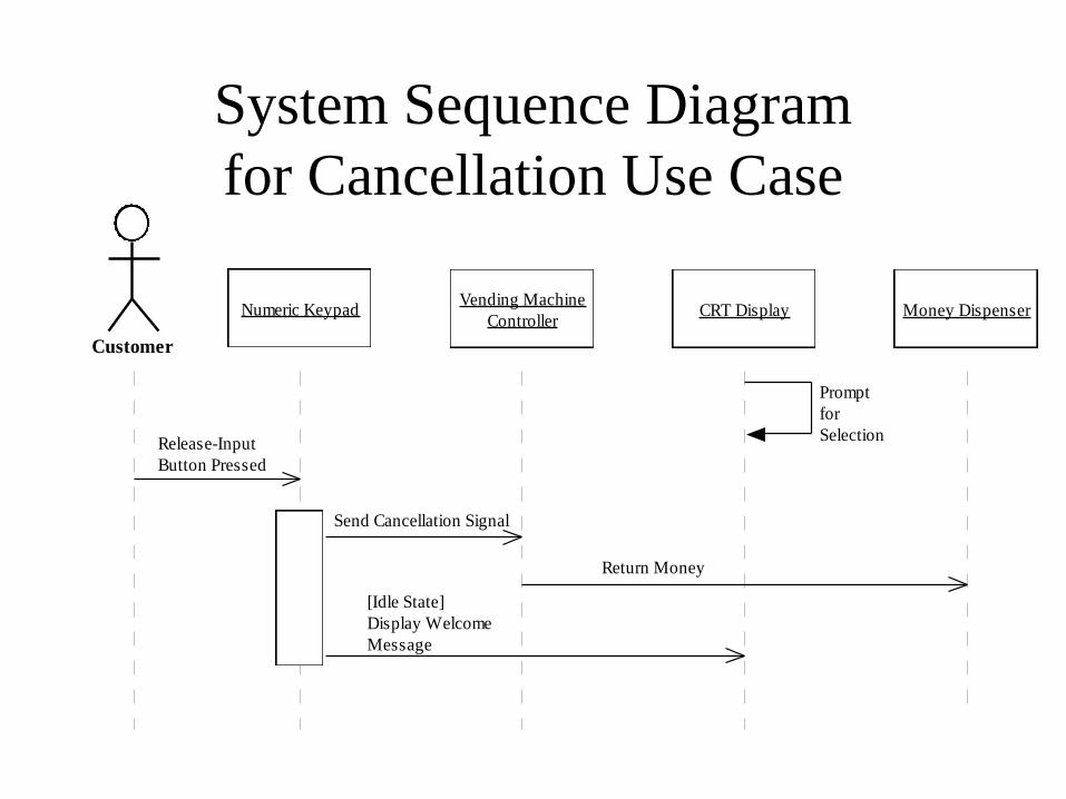
System Sequence Diagram
for Cancellation Use Case
Customer
Numeric Keypad CRT DisplayVending Machine
ControllerMoney Dispenser
Prompt
for
SelectionRelease-Input
Button Pressed
Send Cancellation Signal
[Idle State]
Display Welcome
Message
Return Money
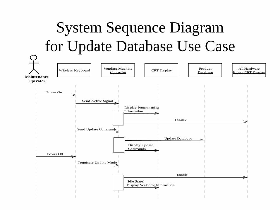
System Sequence Diagram
for Update Database Use Case
Maintenance
Operator
All Hardware
Except CRT DisplayCRT Display
Vending Machine
Controller
Product
DatabaseWireless Keyboard
Power On
Send Active Signal
Display Programming
Information
Disable
Enable
Send Update Commands
Update Database
Power Off
[Idle State]
Display Welcome Information
Display Update
Commands
Terminate Update Mode
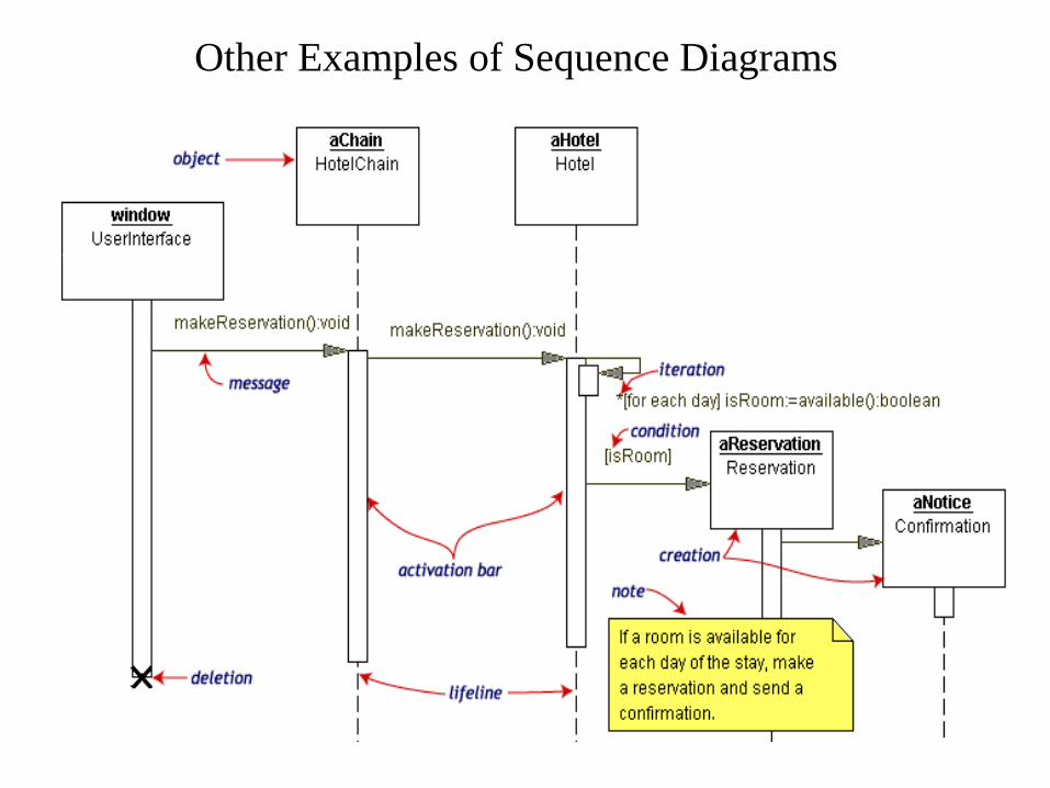
Other Examples of Sequence Diagrams
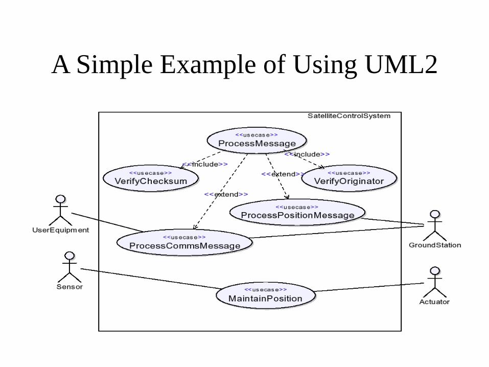
A Simple Example of Using UML2
• EXAMPLE: SATELLITE CONTROL
SYSTEM
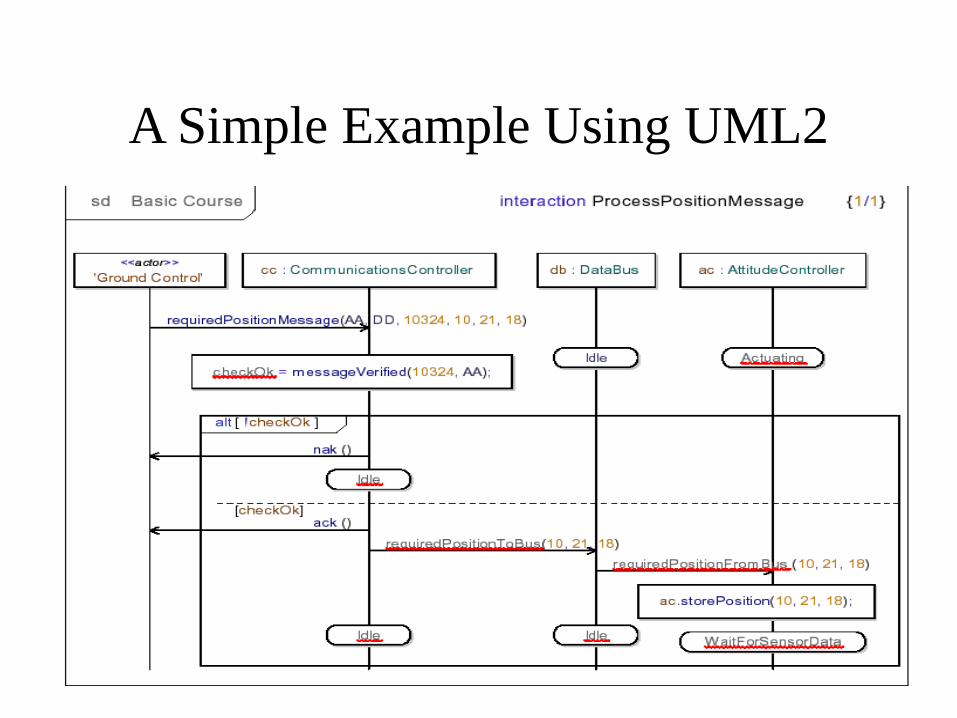
A Simple Example Using UML2
• SATELLITE CONTROL SYSTEM
Architectural behavior