ɷuml demystified by paul kimmel
DESCRIPTION
ɷUml demystified by paul kimmelTRANSCRIPT


This page intentionally left blank
UML DEMYSTIFIED
PAUL KIMMEL
McGraw-Hill/Osborne
New York Chicago San Francisco Lisbon LondonMadrid Mexico City Milan New Delhi San Juan
Seoul Singapore Sydney Toronto

Copyright © 2005 by The McGraw-Hill Companies. All rights reserved. Manufactured in the United States of America. Except aspermitted under the United States Copyright Act of 1976, no part of this publication may be reproduced or distributed in any formor by any means, or stored in a database or retrieval system, without the prior written permission of the publisher.
0-07-148671-2
The material in this eBook also appears in the print version of this title: 0-07-226182-X.
All trademarks are trademarks of their respective owners. Rather than put a trademark symbol after every occurrence of a trade-marked name, we use names in an editorial fashion only, and to the benefit of the trademark owner, with no intention of infringe-ment of the trademark. Where such designations appear in this book, they have been printed with initial caps.
McGraw-Hill eBooks are available at special quantity discounts to use as premiums and sales promotions, or for use in corporatetraining programs. For more information, please contact George Hoare, Special Sales, at [email protected] or (212)904-4069.
TERMS OF USE
This is a copyrighted work and The McGraw-Hill Companies, Inc. (“McGraw-Hill”) and its licensors reserve all rights in and to thework. Use of this work is subject to these terms. Except as permitted under the Copyright Act of 1976 and the right to store andretrieve one copy of the work, you may not decompile, disassemble, reverse engineer, reproduce, modify, create derivative worksbased upon, transmit, distribute, disseminate, sell, publish or sublicense the work or any part of it without McGraw-Hill’s prior con-sent. You may use the work for your own noncommercial and personal use; any other use of the work is strictly prohibited. Your rightto use the work may be terminated if you fail to comply with these terms.
THE WORK IS PROVIDED “AS IS.” McGRAW-HILL AND ITS LICENSORS MAKE NO GUARANTEES OR WARRANTIESAS TO THE ACCURACY, ADEQUACY OR COMPLETENESS OF OR RESULTS TO BE OBTAINED FROM USING THEWORK, INCLUDING ANY INFORMATION THAT CAN BE ACCESSED THROUGH THE WORK VIA HYPERLINK OR OTH-ERWISE, AND EXPRESSLY DISCLAIM ANY WARRANTY, EXPRESS OR IMPLIED, INCLUDING BUT NOT LIMITED TOIMPLIED WARRANTIES OF MERCHANTABILITY OR FITNESS FOR A PARTICULAR PURPOSE. McGraw-Hill and its licen-sors do not warrant or guarantee that the functions contained in the work will meet your requirements or that its operation will beuninterrupted or error free. Neither McGraw-Hill nor its licensors shall be liable to you or anyone else for any inaccuracy, error oromission, regardless of cause, in the work or for any damages resulting therefrom. McGraw-Hill has no responsibility for the con-tent of any information accessed through the work. Under no circumstances shall McGraw-Hill and/or its licensors be liable for anyindirect, incidental, special, punitive, consequential or similar damages that result from the use of or inability to use the work, evenif any of them has been advised of the possibility of such damages. This limitation of liability shall apply to any claim or cause what-soever whether such claim or cause arises in contract, tort or otherwise.
DOI: 10.1036/007226182X

We hope you enjoy thisMcGraw-Hill eBook! If
you’d like more information about this book,its author, or related books and websites,please click here.
Professional
Want to learn more?

In loving memory of my sister Jennifer Annewho was given just 35 years.

ABOUT THE AUTHOR
Paul Kimmel is the Chief Architect and a founder of Software Conceptions, Inc.He has been designing and implementing object-oriented software since 1990 andhas more than a dozen years of experience with modeling languages and was anearly adopter of the Unified Modeling Language. Paul has helped design andimplement solutions using the UML for some of the largest corporations in theworld from international banks, multinational telecommunications companies,logistics and shipping companies, Department of Defense agencies and nationaland international governmental groups.
Copyright © 2005 by The McGraw-Hill Companies. Click here for terms of use.
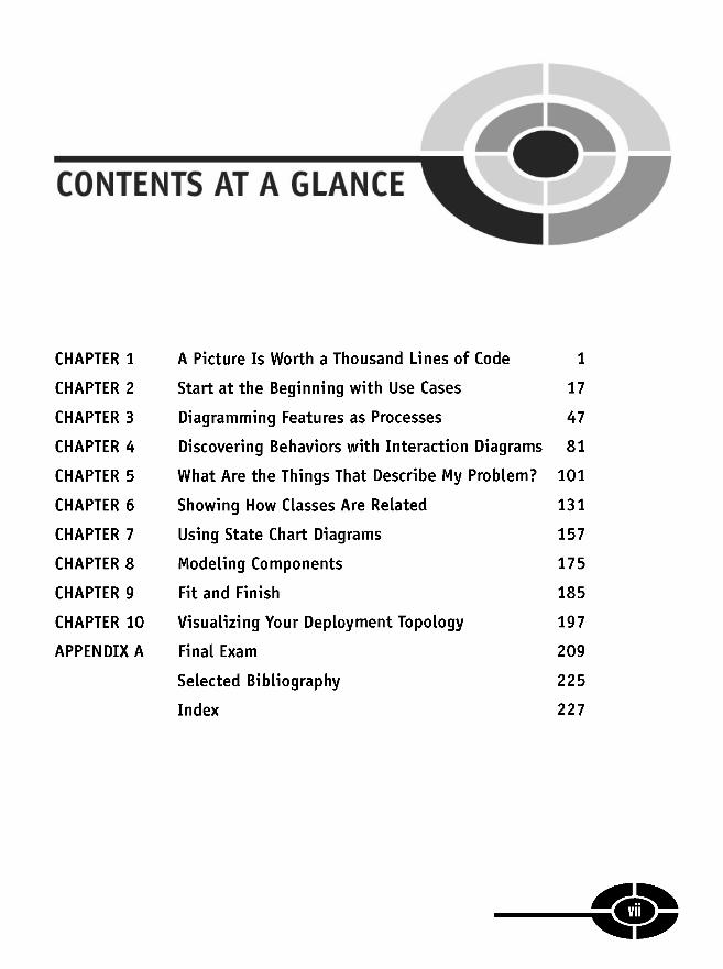
CONTENTS AT A GLANCE
CHAPTER 1
CHAPTER 2
CHAPTER 3
CHAPTER 4
CHAPTER 5
CHAPTER 6
CHAPTER 7
CHAPTER 8
CHAPTER 9
CHAPTER 10
APPENDIX A
A Picture Is Worth a Thousand Lines of Code 1
Start at the Beginning with Use Cases 17
Diagramming Features as Processes 47
Discovering Behaviors with Interaction Diagrams 81
What Are the Things That Describe My Problem? 101
Showing How Classes Are Related
Using State Chart Diagrams
Modeling Components
Fit and Finish
Visualizing Your Deployment Topology
Final Exam
Selected Bibliography
Index
131
157
175
185
197
209
225
227
vii

This page intentionally left blank
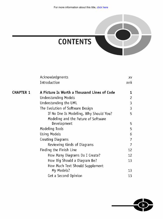
CONTENTS
Acknowledgments xvIntroduction xvii
CHAPTER 1 A Picture Is Worth a Thousand Lines of Code 1
Understanding Models 2
Understanding the UML 3
The Evolution of Software Design 3
If No One Is Modeling, Why Should You? 5
Modeling and the Future of SoftwareDevelopment 5
Modeling Tools 5
Using Models 6
Creating Diagrams 7
Reviewing Kinds of Diagrams 7
Finding the Finish Line 12
How Big Should a Diagram Be? 13
How Much Text Should SupplementMy Models? 13
Get a Second Opinion 13
ix
12howwmanyakfainisahbfiuadictrerafgatrflaserjlsndfilamnfdllll
For more information about this title, click here

CHAPTER 2
CHAPTER 3
UML Demystified
Contrasting Modeling Languages with Process 14
Quiz 14
Answers 16
Start at the Beginning with Use Cases 17
Making the Case for Use Cases 18
Prioritizing Capabilities 19
Communicating with Nontechnophiles 20
Using Use Case Symbols 21
Actor Symbols 21
Use Cases 21
Connectors 22
Including and Extending Use Cases 25
Annotating Use Case Diagrams 27
Creating Use Case Diagrams 32
How Many Diagrams Is Enough? 34
Example Use Case Diagrams 34
Driving Design with Use Cases 43
Quiz 44
Answers 46
Diagramming Features as Processes 47
Elaborating on Features as Processes 48
A Journey toward Code 48
Understanding Activity Diagram Uses 49
Using Activity Diagram Symbols 51
Initial Node 52
Control Flow 52
Actions 56
Decision and Merge Nodes 62
Transition Forks and Joins 63
Partitioning Responsibility with Swimlanes 63
Indicating Timed Signals 67
Capturing Input Parameters 70
X
CONTENTS
CHAPTER 4
CHAPTER 5
Showing Exceptions in Activity Diagrams 70
Terminating Activity Diagrams 71
Creating Activity Diagrams 72Reengineering Process 73
Reengineering a Subactivity 74
Knowing When to Quit 77
Quiz 77
Answers 79
Discovering Behaviors withInteraction Diagrams 81
Elements of Sequence Diagrams 82
Using Object Lifelines 83
Activating a Lifeline 84
Sending Messages 85
Adding Constraints and Notes 87
Using Interaction Frames 87
Understanding What Sequences Tell Us 91
Discovering Objects and Messages 92
Elements of Collaboration (or Communication)Diagrams 94
Equating Design to Code 96
Quiz 97
Answers 99
What Are the Things That DescribeMy Problem? 101
Elements of Basic Class Diagrams 102
Understanding Classes and Objects 103
Modeling Relationships in Class Diagrams 111
Stereotyping Classes 117
Using Packages 118
Using Notes and Comments 118
Constraints 118
XI
CHAPTER 6
CHAPTER 7
UML Demystified
Modeling Primitives 120
Modeling Enumerations 121
Indicating Namespaces 122
Figuring Out the Classes You Need 123
Using the Naive Approach 124
Discovering More than DomainAnalysis Yields 124
Quiz 128
Answers 130
Showing How Classes Are Related 131
Modeling Inheritance 132
Using Single Inheritance 132
Using Multiple Inheritance 135
Modeling Interface Inheritance 139
Whiteboarding 139
Using Realization 140
Describing Aggregation and Composition 143
Showing Associations and Association Classes 145
Exploring Dependency Relationships 150
Adding Details to Classes 153
Quiz 153
Answers 155
Using State Chart Diagrams 157
Elements of a State Diagram 158
Exploring State Symbols 159
Exploring Transitions 164
Creating Behavioral State Machines 166
Creating Protocol State Machines 167
Implementing State Diagrams 168
Quiz 172
Answers 173
• •Xll
CONTENTS
CHAPTER 8
CHAPTER 9
CHAPTER 10
Modeling Components 175
Introducing Component-Based Design 177
Using a Top-Down Approach to Design 177
Using a Bottom-Up Approach to Design 178
Modeling a Component 178
Specifying Provided and Required Interfaces 179
Exploring Component Modeling Styles 180
Diagramming Components for Consumers 180
Diagramming Components for Producers 182
Quiz 183
Answers 184
Fit and Finish 185
Modeling Dos and Don'ts 186
Don't Keep Programmers Waiting 187
Work from a Macro View to a Micro View 187
Document Sparingly 187
Find an Editor 188
Be Selective about DiagramsYou Choose to Create 188
Don't Count on Code Generation 188
Model and Build from Most Riskyto Least Risky 188
If It's Obvious Don't Model It 189
Emphasize Specialization 189
Using Known State Patterns 189
Refactoring Your Model 192
Adding Supporting Documentation 192
Validating Your Model 193
Quiz 193
Answers 195
Visualizing Your Deployment Topology 197
Modeling Nodes 198
Showing Artifacts in Nodes 201
Xlll

UML Demystified
Adding Communication Paths 204
Quiz 206
Answers 207
APPENDIX A Final Exam 209
Answers 223
Selected Bibliography 225
Index 227
XIV

ACKNOWLEDGMENTS
Well into my second decade of writing I have Wendy Rinaldi at McGraw-Hill/Osborne,along with Alexander McDonald and my agent David Fugate at Waterside to thank forthis opportunity to write what I believe you will find an informative, entertaining, andeasy to follow book on the Unified Modeling Language.
I also want to thank my friend Eric Cotter from Portland, Oregon, for offering toprovide technical editing for UML DeMystified. Eric did an excellent job of finding mymistakes, omissions, and in improving the explanations.
Thank you to my hosts at the Ministry of Transportation Ontario in St. Catharines,Ontario. Collaborating with you on CIMS was an enjoyable process and exploringmy models and designs with you provided excellent fodder for this book. Thank youNovica Kovacevic, Jennifer Fang, Rod, Marco Sanchez, Chris Chartrand, SergeyKhudoyarov, Dalibor Skacic, Michael Lam, Howard Bertrand, and David He fromMicrosoft. It was a pleasure working with and learning from all of you.
In 2004, along with Bill Maas, Paul Emery, Sainney Drammeh, BunmiAkinyemichu, and Ryan Doom, the Greater Lansing area .NET Users Group (glugnet.org) was formed, and I'd like to say hello to all of the great glugnet members andsupporters. We meet the third Thursday of every month at 6:00 P.M. on the beautifulcampus of Michigan State University. Thanks to MSU for permitting to use theirexcellent facilities in the Engineering Building and Anthony Hall.
While working in Ontario my sustenance was graciously provided for at Prudhom-mes in Vineland, Ontario, at exit 55 and 57 and the Honest Lawyer in St. Catharines,Ontario, Canada. Thanks to Lis, Jen Cheriton, Everett, Kathryn, and Kim for food andadult beverage, and the staff of the Honest Lawyer for the wireless access.
Last but not least, I owe a gratitude of debt to my wife Lori and four children, Trevor,Douglas, Alex, and Noah, playing the role of biggest fans and supporters. A family isthe greatest blessing. (I would also like to introduce the newest member of our familyLeda, an energetic chocolate lab, who waits patiently at my feet as a subtle reminder topush back from the computer and go do something else every once in a while.)
XV
Copyright © 2005 by The McGraw-Hill Companies. Click here for terms of use.

This page intentionally left blank
INTRODUCTION
New inventions often occur out of necessity and are documented on napkins longbefore, if ever, an authoritative and formal definition is provided. The Unified ModelingLanguage (UML) is just such an example. Individual aspects of what ultimately becamethe UML were defined by Ivar Jacobson, James Rumbaugh, and Grady Booch out ofnecessity long before their individual contributions were consolidated into a singledefinition.
There is a mixed problem with formal and standard specifications. Generally, for anaugust body of scientists to ratify something it is to be unambiguously and rigorouslydefined. If you look up the definition of the UML, you will find meta-models thatdescribe to minute detail what is and what is not the UML. The effect is much likereading congressional reports: long-winded, dry, tedious, and with an occasional juicytidbit. Think of formal definitions versus practical applications like this: there arespecific rigorous rules that define something as simple as algebra, but you don't need toknow them even though we perform or rely on simple algebra in everyday tasks suchas pumping gas. For example, price per gallon multiplied by number of gallons = totalprice. With simple text-to-character substitution we can create arithmetic equations,p * g = t, that start to look like those confusing equations from school but make itnotationally convenient to determine any quantity of the equation. What I mean is thateven people that would identify themselves as math challenged perform math everydayfor practical purposes without ever thinking of it what they are doing as solving mathproblems.
That's the objective behind this book. There are formal and rigorous definitions ofthe UML and they exist for good reason, but you don't have to know them to use theUML in a practical way. UML linguists have to know the UML intimately to rigorouslydefine just like English professors know grammar intimately to teach it, but you don'thave to be an English teacher to communicate effectively. This is true of the UMLtoo; you don't have to know every detail about the UML to use it effectively.
xvii
Copyright © 2005 by The McGraw-Hill Companies. Click here for terms of use.

UML Demystified
UML DeMystified is written in simple prose and designed to make the UMLpractical and an effective tool for communicating software analysis and design.
There are many books on process and the UML does not define a process. However,this book is organized in such a manner that if you create the kinds of models asneeded in the order in which they appear in this book, then you have a practicalbeginning of a usable process.
UML DeMystified is a modest-sized book but it is a compilation of more thana dozen years of practical experience working with some of the largest and bestknown companies in the world as well as many well-known smaller companies, andthe UML described in this book is pragmatic, practical, and applicable whether youare building small, medium, or very large applications. In short, UML DeMystifiedleaves the ivory tower fluff and rigor to other texts and tells you what you need toknow to successfully use the UML to describe software.
r ••>kvnjj

CHAPTER
A Picture IsWorth a Thousand
Lines of Code
Pictures of little stick people represent the oldest recorded form of communicationin human history. Some of these cave art have been dated to be as old as 75,000years. Oddly enough, here we are at the turn of the twenty-first modern century, andwe are still using little stick figures to convey information. That's right, a little stickman we'll call Esaw is a central character in one of the newest languages developedby humans (Figure 1-1).
1
1
Copyright © 2005 by The McGraw-Hill Companies. Click here for terms of use.

UML Demystified
Figure 1-1 Esaw, who is referred to as an actor in the UML.
The language I am talking about is called the Unified Modeling Language, orUML. The UML is a language just as sure as, Pascal, C# (C sharp), German, English,and Latin are languages. And the UML is probably one of the newest languages in-vented by humankind, invented around 1997.
As with other languages, the UML was invented out of necessity. Moreover, aswith many languages, the UML uses symbols to convey meaning. However, unlikeorganic languages such as English or German that evolve over time from commonuse and adaptation, the UML was invented by scientists, which unfortunately is aproblem. Scientists are very smart, but they often are not very good at explainingthings to those less scientific. This is where I come in.
In this chapter we will look at the origin and evolution of the UML. We also willtalk about how to create pictures using the UML, how many and what types of pic-tures to create, what those pictures should convey, and most important, when to stopdrawing pictures and start writing code.
Understanding ModelsA model is a collection of pictures and text that represent something—for our pur-poses, software. (Models do not have to represent software, but we will narrow ourscope to software models.) A model is to software what a blueprint is to a house.
Models are valuable for many specific reasons. Models are valuable becausethey consist of pictures to a large extent, and even simple pictures can convey moreinformation than a lot of text, e.g., code. This is consistent with the somewhat mod-ified old adage that a picture speaks a thousand lines of code. Models are valuablebecause it is easier to draw some simple pictures than it is to write code or even textthat describes the same thing. Models are valuable because it is cheaper, faster, andit is easier to change models than it is to change code. The simple truth is that cheap,fast, easy, and flexible are what you want when you are solving problems.
2
CHAPTER 1 A Picture Is Worth a Thousand Lines of Code
Unfortunately, if everyone uses different pictures to mean the same thing, thenthe pictures add to the confusion rather than mitigate it. This is where the UMLcomes in.
Understanding the UMLThe UML is an official definition of a pictoral language where there are commonsymbols and relationships that have one common meaning. If every participantspeaks UML, then the pictures mean the same thing to everyone looking at thosepictures. Learning the UML, therefore, is essential to being able to use pictures tocheaply, flexibly, and quickly experiment with solutions.
It is important to reiterate here that it is faster, cheaper, and easier to solve prob-lems with pictures than with code. The only barrier to benefiting from modeling islearning the language of modeling.
The UML is a language just like English or Afrikaans is a language. The UMLcomprises symbols and a grammar that defines how those symbols can be used.Learn the symbols and grammar, and your pictures will be understandable by every-one else who recognizes those symbols and knows the grammar.
Why the UML, though? You could use any symbols and rules to create your ownmodeling language, but the trick would be to get others to use it too. If your aspira-tions are to invent a better modeling language, then it isn't up to me to stop you. Youshould know that the UML is considered a standard and that what the UML is andisn't is defined by a consortium of companies that make up the Object ManagementGroup (OMG). The UML specification is defined and published by the OMG atwww. omg. org.
The Evolution of Software DesignIf you feel that you are late to the UML party, don't fret—you are actually an earlyarrival. The truth is that the UML is late to the software development party. I workall over North America and talk with a lot of people at lots of very big softwarecompanies, and the UML and modeling are just starting to catch on. This is bestexemplified by Bill Gates' own words after his famous "think week" in 2004, whereGates is reported to have talked about the increasing importance of formal analysisand design (read UML) in the future. This sentiment is also supported by Micro-soft's very recent purchase of Visio, which includes UML modeling capabilities.
3
UML Demystified
The UML represents a formalization of analysis and design, and formalizationalways seems to arrive last. Consider car makers in the last century. Around the turnof the last century, every buggy maker in Flint, Michigan, was turning horse car-riages into motorized carriages, i.e., cars. This occurred long before great universitiessuch as Michigan State University (MSU) were turning out mechanical engineerstrained to build cars and software tools such as computer-aided design (CAD) pro-grams that are especially good at drawing complex items such as car parts. Theevolution of formalized automobile engineering is consistent with the evolution offormalized software engineering.
About 5000 years ago, the Chinese created one of the first computers, the abacus.About 150 years ago, Charles Babbage invented a mechanical computing machine.In 1940, Alan Turing defined the Turing computing machine and Presper Eckertand John Mauchly invented Eniac. Following computing machines came punchcards and Grace Hopper's structured analysis and design to support Cobol develop-ment. In the 1960s, Smalltalk, an object-oriented language, was invented, and in1986, Bjarne Stroustrop invented what is now known as C++. It wasn't until aroundthis same time period—the 1980s—that very smart men like Ivar Jacobson, JamesRumbaugh, and Grady Booch started defining elements of modern software analy-sis and design, what we now call the UML.
In the late 1980s and early 1990s, modeling notation wars were in full gear, withdifferent factions supporting Jacobson, Rumbaugh, or Booch. Remember, it wasn'tuntil 1980 that the average person could purchase and own—and do something use-ful with—a personal computer (PC). Jacobson, Rumbaugh, and Booch each useddifferent symbols and rules to create their models. Finally, Rumbaugh and Boochbegan collaborating on elements of their respective modeling languages, and Jacob-son joined them at Rational Software.
In the mid-1990s, the modeling elements of Rumbaugh [Object Modeling Tech-nique (OMT)], Booch (Booch method), and Jacobson (Objectory and Use Cases)—Rumbaugh, Jocobson, and Rumbaugh are referred to as "the three amigos"—weremerged together to form the unified modeling process. Shortly thereafter, process wasremoved from the modeling specification, and the UML was born. This occurred veryrecently, in just 1997. The UML 2.0 specification stabilized in October 2004; that'sright, we are just now on version 2.
This begs the question: Just how many companies are using the UML and actu-ally designing software with models? The answer is still very few. I work all overNorth America and personally know people in some very successful software com-panies, and when I ask them if they build software with the UML, the answer isalmost always no.
4

CHAPTER 1 A Picture Is Worth a Thousand Lines of Code
If No One Is Modeling, Why Should You?
A rational person might ask: Why then, if Bill Gates is making billions writingsoftware without a significant emphasis on formal modeling, should I care aboutthe UML? The answer is that almost 80 percent of all software projects fail. Theseprojects exceed their budgets, don't provide the features customers need or desire,or worse, are never delivered.
The current trend is to outsource software development to developing or third-world nations. The basic idea is that if American software engineers are failing,then perhaps paying one-fifth for a Eurasian software developer will permit compa-nies to try five times as often to succeed. What are these outsourcing companiesfinding? They are discovering that the United States has some of the best talent andresources available and that cheap labor in far-away places only introduces addi-tional problems and is no guarantee of success either. The real answer is that moretime needs to be spent on software analysis and design, and this means models.
Modeling and the Future of Software Development
A growing emphasis on formal analysis and design does not mean the end of thesoftware industry's growth. It does mean that the wild, wild west days of the 1980sand 1990s eventually will come to a close, but it is still the wild, wild hacking westout there in software land and will be for some time.
What an increasing emphasis on software analysis and design means right nowis that trained UML practitioners have a unique opportunity to capitalize on thisgrowing interest in the UML. It also means that gradually fewer projects will fail,software quality should improve, and more software engineers will be expected tolearn the UML.
Modeling ToolsUntil very recently, modeling has been a captive in an ivory tower surrounded by animpenetrable garrison of scientists armed with metamodels and ridiculously expen-sive modeling tools. The cost of one license for a popular modeling tool was in thethousands of dollars; this meant that the average practitioner would have to spendas much on one application for modeling as he or she spent for an entire computer.This is ridiculous.
5
UML Demystified
Modeling tools can be very useful, but it is possible to model on scraps of paper.Thankfully, you don't have to go that far. Love it or hate it, Microsoft is very goodat driving down the cost of software. If you have a copy of MSDN, then you have amodeling tool that is almost free, Visio. Visio is a good tool, ably capable of produc-ing high-quality UML models, and it won't break your budget.1
In keeping with the theme of this book—demystifying UML—instead of break-ing the bank on Together or Rose, we are going to use the value-priced Visio. If youwant to use Rose XDE, Together, or some other product, you are welcome to do so,but after reading this book, you will see that you can use Visio and create profes-sional models and save yourself hundreds or even thousands of dollars.
Using ModelsModels consist of diagrams and pictures. The intent of models is that they arecheaper to produce and experiment with than code. However, if you labor over whatmodels to draw, when to stop drawing and start coding, or whether your models areperfect or not, then you will slowly watch the cost and time value of models dwin-dle away.
You can use plain text to describe a system, but more information can be con-veyed with pictures. You could follow the extreme Programming (XP) dictum andcode away, refactoring as you go, but the details of lines of code are much morecomplex than pictures, and programmers get attached to code but not to pictures.(I don't completely understand the psychology of this code attachment, but it reallydoes exist. Just try to constructively criticize someone else's code, and watch theconversation deteriorate very quickly into name calling.) This means that once codeis written, it is very hard to get buy-in from its coder or a manager to make modifi-cations, especially if the code is perceived to work. Conversely, people will gladlytinker with models and accept suggestions.
Finally, because models use simple symbols, more stakeholders can participatein design of the system. Show an end user a hundred lines of code, and you can hearthe crickets chirping; show such an end user an activity diagram, and that sameperson can tell you if you have captured the essence of how that task is performedcorrectly.
'Microsoft has a new program that permits you to purchase MSDN Universal, which includes Visio,for $375. This is an especially good value.
6

CHAPTER 1 A Picture Is Worth a Thousand Lines of Code
Creating DiagramsThe first rule of creating models is that code and text are time-consuming, and wedon't want to spend a lot of time creating text documents that no one wants to read.What we do want to do is to capture the important parts of the problem and a solu-tion accurately. Unfortunately, this is not a prescription for the number or variety ofdiagrams we need to create, and it does not indicate how much detail we need toadd to those diagrams.
Toward the end of this chapter, in the section "Finding the finsh line.", I will talkmore about how one knows that one has completed modelling. Right now, let's talkabout the kinds of diagram we may want to create.
Reviewing Kinds of DiagramsThere are several kinds of diagrams that you can create. I will quickly review thekinds of diagrams you can create and the kinds of information each of these dia-grams is intended to convey.
Use Case Diagrams
Use case diagrams are the equivalent of modern cave art. A use case's main sym-bols are the actor (our friend Esaw) and the use case oval (Figure 1-2).
Use case diagrams are responsible primarily for documenting the macro require-ments of the system. Think of use case diagrams as the list of capabilities the systemmust provide.
Activity Diagrams
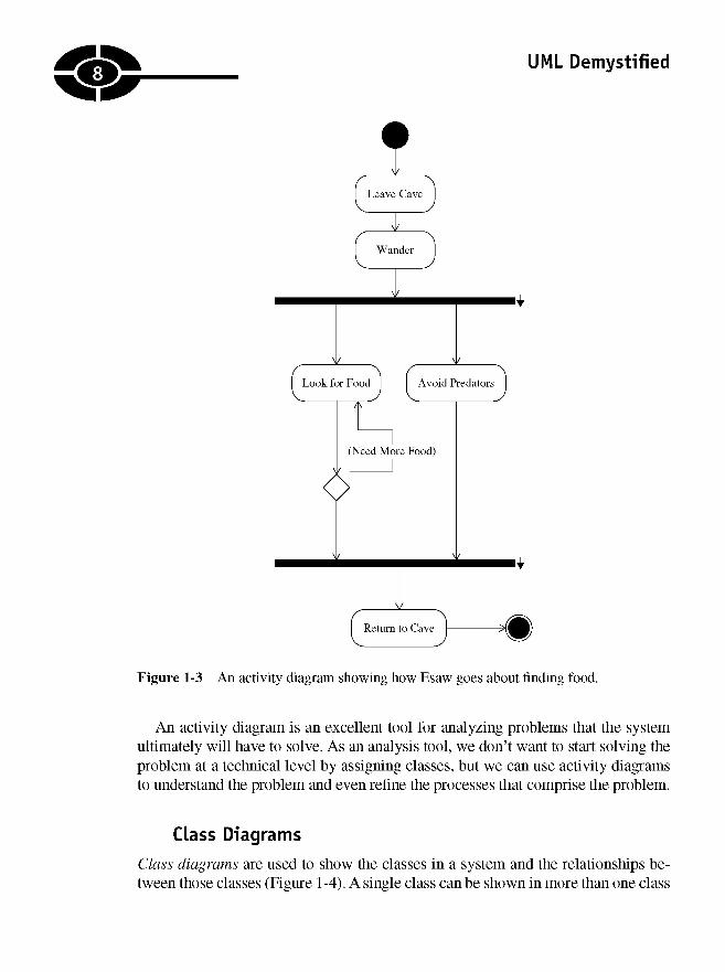
An activity diagram is the UML version of a flowchart. Activity diagrams are usedto analyze processes and, if necessary, perform process reengineering (Figure 1-3).
Figure 1-2 The "FindFood" use case.
7
UML Demystified
Figure 1-3 An activity diagram showing how Esaw goes about finding food.
An activity diagram is an excellent tool for analyzing problems that the systemultimately will have to solve. As an analysis tool, we don't want to start solving theproblem at a technical level by assigning classes, but we can use activity diagramsto understand the problem and even refine the processes that comprise the problem.
Class Diagrams
Class diagrams are used to show the classes in a system and the relationships be-tween those classes (Figure 1-4). A single class can be shown in more than one class
a

a
Figure 1-4 A single class diagram, perhaps one of many, that conveys a facet of thesystem being designed.
diagram, and it isn't necessary to show all the classes in a single, monolithic classdiagram. The greatest value is to show classes and their relationships from variousperspectives in a way that will help convey the most useful understanding.
Class diagrams show a static view of the system. Class diagrams do not describebehaviors or how instances of the classes interact. To describe behaviors and inter-actions between objects in a system, we can turn to interaction diagrams.
Interaction Diagrams
There are two kinds of interaction diagrams, the sequence and the collaboration.These diagrams convey the same information, employing a slightly different per-spective. Sequence diagrams show the classes along the top and messages sentbetween those classes, modeling a single flow through the objects in the system.Collaboration diagrams use the same classes and messages but are organized ina spatial display. Figure 1-5 shows a simple example of a sequence diagram, andFigure 1-6 conveys the same information using a collaboration diagram.
A sequence diagram implies a time ordering by following the sequence of mes-sages from top left to bottom right. Because the collaboration diagram does notindicate a time ordering visually, we number the messages to indicate the order inwhich they occur.
Some tools will convert interaction diagrams between sequence and collabora-tion automatically, but it isn't necessary to create both kinds of diagrams. Generally,a sequence diagram is perceived to be easier to read and more common.
9CHAPTER 1 A Picture Is Worth a Thousand Lines of Code

UML Demystified
Figure 1-5 A single sequence diagram demonstrating how food is gathered and prepared.
State Diagrams
Whereas interaction diagrams show objects and the messages passed between them,a state diagram shows the changing state of a single object as that object passes througha system. If we continue with our example, then we will focus on Esaw and how hisstate is changing as he forages for food, finds food, and consumes it (Figure 1-7).
REMEMBER Demystified the UML is a language. Like programming or spokenlanguages, idioms that you don't use frequently may become a little rusty from disuse.It is perfectly acceptable to look up a particular idiom. The goal of modeling is tocapture the essence of modeling and to design proficiently and, ultimately, as accuratelyas possible without getting stuck arbitrating language elements. Unfortunately, UMLtools aren 't as accurate as compilers in describing language errors.
10

CHAPTER 1 A Picture Is Worth a Thousand Lines of Code
Figure 1-6behavior.
A collaboration diagram that conveys the same gathering and consuming
Component Diagrams
The UML defines various kinds of models, including analysis, design, and imple-mentation models. However, there is nothing forcing you to create or maintain threemodels for one application. An example of a diagram you might find in an imple-mentation model is a component diagram. A component diagram shows thecomponents—think subsystems—in the final product.
Figure 1-7 A state diagram (or statecharf) showing the progressive state as Esaw foragesand eats.
11

UML Demystified
I'll cover deployment diagrams later in this book but defer citing an example fornow. Generally, a component diagram is a bit like a class diagram with componentsymbols.
Other Diagrams
There are other kinds or variations of diagrams we can create. For example, a de-ployment topology diagram will show you what your system will look like deployed.Such a diagram typically contains symbols representing things such as Web servers,database servers, and various and sundry devices and software that make up yoursolution. This kind of diagram is more common when you are building «-tiereddistributed systems.
I will show you examples of some of these diagrams later in this book. Rememberthat the key to modeling is to modeling interesting aspects of your system that helpto clarify elements that may not be obvious, as opposed to modeling everything.
Finding the Finish LineThe hardest part of modeling is that it is so new that UML models are subjected tosome of the same language wars object-oriented projects suffered from during thelast decade. I encourage you to avoid these language wars as mostly unproductiveacademic exercises. If you find yourself getting hung up on whether something isor isn't good UML, then you are heading toward analysis (and design) paralysis.
The goal is to be as accurate as possible in a reasonable amount of time. Poorlydesigned software is bad enough, but no software is almost always worse. To deter-mine if you are finished with a particular diagram or model, ask the question: Doesthe diagram or model convey my understanding, meaning, and intent? That is, is thediagram or model good enough? Accuracy is important because others need to readyour models, and idiomatic mistakes mean that the models will be harder for othersto read.
How Many Diagrams Do I Create?
There is no specific answer. A better question is: Do I have to create every kind ofdiagram? The answer to this question is no. A refinement of this answer is that it ishelpful to create diagrams that resolve persnickety analysis and design problemsand diagrams that people actually will read.
12

CHAPTER 1 A Picture Is Worth a Thousand Lines of Code
How Big Should a Diagram Be?Determining how big a model needs to be is another good question to decide. Ifa given model is too big, then it may add to confusion. Try to create detailed mod-els — but not too detailed. As with programming, creating UML models takespractice.
Solicit feedback from different constituencies. If the end users think that an anal-ysis diagram adequately and correctly captures the problem, then move on. If theprogrammers can read a sequence and figure out how to implement that sequence,then move on. You can always add details if you must.
How Much Text Should Supplement My Models?A fundamental idea for using pictures for modeling instead of long-winded text isthat pictures convey more meaning in a smaller space and are easier to manipulate.If you add too much text — constraints, notes, or long documents — then you aredefeating the purpose of this more concise pictorial notation.
The best place for text is the use case. A good textual description in each use casecan clarify precisely what feature that use case supports. I will demonstrate somegood use case descriptions in Chapter 2.
You are welcome to add any clarifying text you need, but the general rule for textis analogous to the rule for comments in code: Only comment things that are rea-sonably subject to interpretation.
Finally, try to document everything in your modeling tool as opposed to a sepa-rate document. If you find that you need or the customer requires a writtenarchitectural overview, defer this until after the software has been produced.
Get a Second OpinionIf you find yourself getting stuck on a particular diagram, get a second opinion.Often, putting a diagram aside for a couple of hours or getting a second opinion willhelp you to resolve issues about one model. You may find that the end user of thatmodel will understand your meaning or provide more information that clears up theconfusion, or a second set of eyes may yield a ready response. A critical element toall software development is to build some inertia and capture the macro, or big,concepts without getting stuck or keeping users waiting.
13
UML Demystified
Contrasting Modeling Languageswith Process
The UML actually began life as the Unified Process. The inventors quickly realizedthat programming languages do not dictate process, and neither should modelinglanguages. Hence process and language were divided.
There are many books on process. I don't think one process represents the bestfit for all projects, but perhaps one of the more flexible processes is the RationalUnified Process. My focus in this book is on the UML, not on any particular pro-cess. I will be suggesting the kinds of models to create and what they tell you, but Iencourage you to explore development processes for yourself. Consider exploringthe Rational Unified Process (RUP), the Agile process, extreme Programming(XP), and even Microsoft's Services Oriented Architecture (SOA). (SOAis more ofan architectural approach using elements like XML Web Services, but it offerssome good techniques.)
I am not an expert on every process, but here is a summary that will provide youwith a starting point. The RUP is a buffet of activities centered on the UML thatdefines iterative, small waterfalls macro phases, including inception, elaboration,construction, and transition. XP is constructive hacking. The idea generally is basedon building on your understanding, expecting things to change, and using tech-niques such as refactoring and pair programming to support changes as yourunderstanding grows. Microsoft's SOA depends on technologies like COM+, Re-moting, and XML Web Services and a separation of responsibilities by services.Agile is a new methodology that I don't understand completely, but Dr. Boehm'sbook, Balancing Agility and Discipline, compares it with XP, and I suspect thatconceptually it lives somewhere between RUP and XP.
It is important to keep in mind that many of the people or entities offering a pro-cess may be trying to sell you something, and some very good ideas have comefrom each of these parties.
Quiz1. What does the acronym UML mean?
a. Uniform Model Language
b. Unified Modeling Language
c. Unitarian Mock-Up Language
d. Unified Molding Language
14

CHAPTER 1 A Picture Is Worth a Thousand Lines of Code
2. The UML is used only to model software.
a. True
b. False
3. What is the name of the process most closely associated with the UML?
a. The modeling process
b. The Rational Unified Process
c. eXxtreme Programming
d. Agile methods
4. What is the name of the standards body that defines the UML?
a. Unified Modeling Group
b. Object Modeling Group
c. Object Management Group
d. The Four Amigos
5. Use case diagrams are used to capture macro descriptions of a system.
a. True
b. False
6. Sequence diagrams differ from collaboration diagrams (choose all thatapply).
a. Sequence diagrams are interaction diagrams; collaboration diagramsare not.
b. Sequence diagrams represent a time ordering, and collaboration diagramsrepresent classes and messages, but time ordering is not implied.
c. Time order is indicating by numbering sequence diagrams.
d. None of the above
7. A class diagram is a dynamic view of the classes in a system.
a. True
b. False
8. A good UML model will contain at lest one of every kind of diagram.
a. True
b. False
15
UML Demystified
9. What is the nickname of the group of scientists most notably associatedwith the UML?
a. The Gang of Four
b. The Three Musketeers
c. The Three Amigos
d. The Dynamic Duo
10. Sequence diagrams are good at showing the state of an object across manyuse cases.
a. True
b. False
Answers1. b
2. b
3. b
4. c
5. a
6. b
7. b
8. b
9. c
10. b
16

CHAPTER
Start at theBeginning with
Use Cases
The Unified Modeling Language (UML) supports object-oriented analysis and de-sign by providing you with a way to capture the results of analysis and design. Ingeneral, we start with understanding our problem, i.e., analysis. An excellent typeof model for capturing analysis is the use case diagram.
The purpose of a use case is to describe how a system will be used—to describeits essential purposes. The purpose of use case diagrams is to capture the essentialpurposes visually.
A well-written and well-diagrammed use case is one of the single most importantkinds of models you can create. This is so because clearly stating, knowing, andorganizing the objectives is singularly important to attaining those objectives suc-cessfully. There is an old proverb that says, "A journey of a thousand miles begins
17
2
Copyright © 2005 by The McGraw-Hill Companies. Click here for terms of use.

UML Demystified
with a single step," and there is a slightly younger proverb that says, "If you don'tknow where you're going, then the journey is never ending."
In this chapter I will talk about a significant first part of such a journey—creatinguse cases—by covering
• The symbols used to create use case diagrams
• How to create use case diagrams
• How many use case diagrams to create
• How much to include in a use case diagram
• The level of detail to include in a use case diagram
• How to express relationships between individual use cases
• The quantity and style of text that is useful for annotating use case diagrams
• Significantly, how to prioritize use cases
Making the Case for Use CasesUse case diagrams look deceptively simple. They consist of stick figures, lines, andovals. The stick figure is called an actor and represents someone or something thatacts on the system. In software development, actors are people or other softwarethat acts on the system. The lines are dotted or solid lines, with or without variousarrows that indicate the relationship between the actor and the ovals. The ovals arethe use cases, and in the use case diagram, these ovals have some text that providesa basic description. Figure 2-1 is a simple example of a use case diagram.
For a long time use case diagrams bugged me. They did so because they seemedtoo simple to be of any value. A child of three or four with a crayon and a piece ofpaper could reproduce these stick figures. Their simplicity is the deception, however.
Figure 2-1 A very simple use case diagram.
18

CHAPTER 2 Start at the Beginning with Use Cases
That a use case diagram is easy to create is implicit praise for the UML. Findingthe right use cases and recording their responsibilities correctly is the deception.Finding the right use cases and describing them adequately is the critical processthat prevents clever software engineers from skipping critical requirements and in-venting unnecessarily. In a nutshell, use case diagrams are a macro record of whatyou want to build.
In the preceding paragraph, I used the word macro. Macro in this context simplymeans "big." The big, or macro, objectives are what are referred to as compellingbusiness arguments, or reasons, for doing something. Use case diagrams capturethe big, compelling objectives. The use case text captures supporting details.
This is what I missed in the stick figure pictures of use case diagrams. I missedthat simply by recording what the system will do and what it won't do, we recordand specify the scope of what we are creating. I also missed that the text that ac-companies use case diagrams fills in the blanks between the macro uses and themicro uses, where micro means "smaller, supporting" uses.
In addition to recording the primary and secondary uses, use case diagrams im-plicitly provide us with several significant opportunities for managing development,which I will go into in more detail as the chapter progresses.
Prioritizing CapabilitiesHave you ever written a to-do list? A to-do list is a list of things that you must do ordesire to do. The act of writing the list is a starting point. Use cases are essentiallyto-do lists. Once you have captured the use cases, you have articulated what thesystem will do, and you can use the list to prioritize our tasks. Both stating and or-ganizing objectives are very critical early tasks.
The value in prioritizing the capabilities of a system is that software is fluid. Letme illustrate what I mean by example. It is possible to create, save, open, and printa text document with both Notepad and Microsoft Word, but the difference in thenumber of lines of code and the number of features between these two programs istremendous. By prioritizing uses, we often have the opportunity to juggle features,budget, and schedule advantageously.
Suppose, for example, that my primary objectives are to be able to create, save,open, and print a text document. Further suppose that my secondary objectives areto save the document as plain text, Hyper Text Markup Language (HTML), and richtext—i.e., special formatting. Prioritizing the capabilities means that I could elect tofocus on primary uses—create, save, open, and print—but defer supporting HTMLand rich text. (Features in software commonly are deferred to later versions owingto the real constraints mentioned earlier, including, time, budget, and a change in thebusiness environment.)
19

UML Demystified
Not having enough time and running out of money are straightforward problems.Software developers are routinely optimistic, get distracted by tangents, and spendmore time in meetings than planned, and these things tax a budget. However, let'stake a moment to examine a change in the business environment. If our originalrequirements were HTML, plain text, and rich text and we were building our soft-ware in the last 5 years, it is perfectly plausible that a customer might say, duringthe middle of development, that saving a document as extensible Markup Lan-guage (XML) text would be more valuable than rich text. Thus, owing to an evolvingtechnological climate, midstream a customer might reprioritize and demand XMLas more important than rich text. Had we not documented our primary and second-ary requirements, then it might be very challenging to determine desirable tradeoffs,such as swapping rich text for XML. Because we clearly recorded desirable usecases, we are able to prioritize and make valuable tradeoffs if we have to.
Communicating with Nontechnophiles
Another thing that I missed about use cases is that their very simplicity makes theman easy conveyance for communicating with nontechnophiles. We call these peopleusers or customers.
Left-brained programmers generally loathe users. The basic idea is that if onecannot read code, then one is dumb or, at least, dumber than those who can. TheUML and use cases bridge the gap between left-brained programmers and nontech-nophile users.
A stick figure, line, and oval are simplistic enough, when combined with sometext, that every participant can understand the meaning. The result is that users andcustomers can look at the drawings and read the plain text and determine if thetechnologists have accurately recorded and understand the desirable features or not.This also means that managers—who may have not written code in 10 years—andtechnical leads can examine the end product and by inspection ensure that rampantinventiveness isn't the cause of missed schedules or absent features. Demonstratingthis dissonance by continuing my earlier example, suppose that rich text support isimplemented anyway because the programmer knows how to store and retrieve richtext. However, because XML is newer and the programmer has less experienceworking with XML, the XML write feature is unmaliciously deferred. A proactivemanager can track a customer's needs as captured by the use cases and preemptunproductive tangents.
Because use cases are visual and simple, users and customers can provide feed-back, and bridge-persons between customers and programmers, such as managers,can determine if features actually built accurately reflect the desires of users.
20
CHAPTER 2 Start at the Beginning with Use Cases
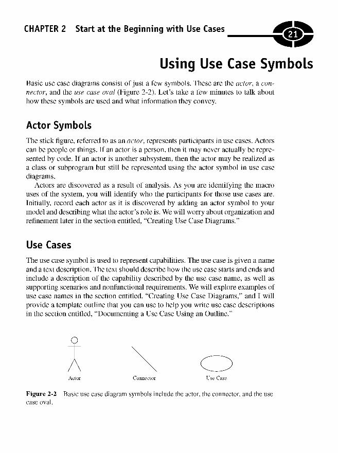
Using Use Case SymbolsBasic use case diagrams consist of just a few symbols. These are the actor, a con-nector, and the use case oval (Figure 2-2). Let's take a few minutes to talk abouthow these symbols are used and what information they convey.
Actor Symbols
The stick figure, referred to as an actor, represents participants in use cases. Actorscan be people or things. If an actor is a person, then it may never actually be repre-sented by code. If an actor is another subsystem, then the actor may be realized asa class or subprogram but still be represented using the actor symbol in use casediagrams.
Actors are discovered as a result of analysis. As you are identifying the macrouses of the system, you will identify who the participants for those use cases are.Initially, record each actor as it is discovered by adding an actor symbol to yourmodel and describing what the actor's role is. We will worry about organization andrefinement later in the section entitled, "Creating Use Case Diagrams."
Use Cases
The use case symbol is used to represent capabilities. The use case is given a nameand a text description. The text should describe how the use case starts and ends andinclude a description of the capability described by the use case name, as well assupporting scenarios and nonfunctional requirements. We will explore examples ofuse case names in the section entitled, "Creating Use Case Diagrams," and I willprovide a template outline that you can use to help you write use case descriptionsin the section entitled, "Documenting a Use Case Using an Outline."
Figure 2-2 Basic use case diagram symbols include the actor, the connector, and the usecase oval.
21
UML Demystified
Connectors
Because use case diagrams can have multiple actors, and because use cases can beassociated with actors and other use cases, use case connectors are used to indicatehow actors and use cases are associated. In addition, connector styles can change toconvey more information about the relationship between actors and use cases.Finally, connectors can have additional adornments and annotations that provideeven more information.
Connector Line Styles
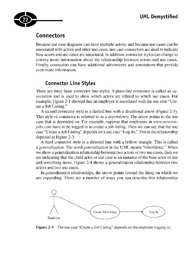
There are three basic connector line styles. A plain-line connector is called an as-sociation and is used to show which actors are related to which use cases. Forexample, Figure 2-1 showed that an employer is associated with the use case "Cre-ate a Job Listing."
A second connector style is a dashed line with a directional arrow (Figure 2-3).This style of connector is referred to as a dependency. The arrow points to the usecase that is depended on. For example, suppose that employers in www.motown-jobs.com have to be logged in to create a job listing. Then we can say that the usecase "Create a Job Listing" depends on a use case "Log-In." This is the relationshipdepicted in Figure 2-3.
A third connector style is a directed line with a hollow triangle. This is calleda generalization. The word generalization in the UML means "inheritance." Whenwe show a generalization relationship between two actors or two use cases, then weare indicating that the child actor or use case is an instance of the base actor or useand something more. Figure 2-4 shows a generalization relationship between twoactors and two use cases.
In generalization relationships, the arrow points toward the thing on which weare expanding. There are a number of ways you can describe this relationship
22
Figure 2-3 The use case "Create a Job Listing" depends on the employer logging in.
CHAPTER 2 Start at the Beginning with Use Cases
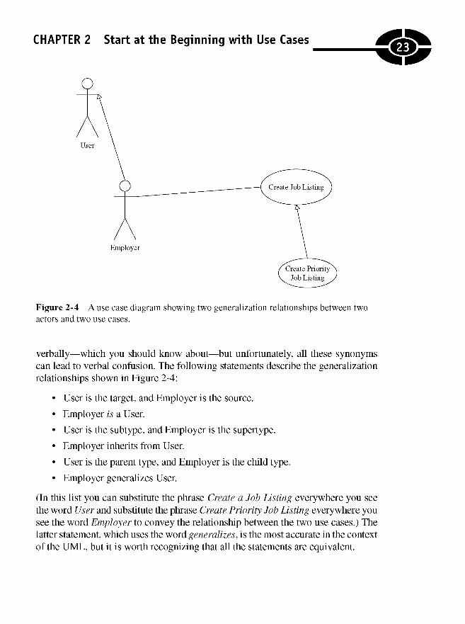
Figure 2-4 A use case diagram showing two generalization relationships between twoactors and two use cases.
verbally—which you should know about—but unfortunately, all these synonymscan lead to verbal confusion. The following statements describe the generalizationrelationships shown in Figure 2-4:
• User is the target, and Employer is the source.
• Employer is a User.
• User is the subtype, and Employer is the supertype.
• Employer inherits from User.
• User is the parent type, and Employer is the child type.
• Employer generalizes User.
(In this list you can substitute the phrase Create a Job Listing everywhere you seethe word User and substitute the phrase Create Priority Job Listing everywhere yousee the word Employer to convey the relationship between the two use cases.) Thelatter statement, which uses the word generalizes, is the most accurate in the contextof the UML, but it is worth recognizing that all the statements are equivalent.
23
UML Demystified
Connector Adornments
UML diagrams encourage less text because pictures convey a lot of informationthrough a convenient visual shorthand, but UML diagrams don't eschew text alto-gether. For example, connectors can include text that indicates endpoint multiplicityand text that stereotypes the connector.
Showing MultiplicityConnectors in general can have multiplicity notations at either end of the connector.The multiplicity notations indicate the possible count of each thing. For example, anasterisk means many. An asterisk next to an actor means that there may be many in-stances of that actor. Although the UML permits notating use case connectors in thisway, it isn't that common. You are more likely to see these notational count marks insuch diagrams as class diagrams, so I will elaborate on multiplicity in Chapter 3.
Stereotyping ConnectorsA more common connector notation is the stereotype. Stereotypes add detail to therelationship between elements in a use case diagram. For example, in Figure 2-3,I introduced the dependency connector. A stereotype can be used to expand on themeaning of the dependency connector.
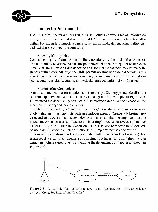
In the section entitled, "Connector Line Styles," I said that an employer can createa job listing and illustrated this with an employer actor, a "Create Job Listing" usecase, and an association connector. However, I also said that the employer must belogged in. When a use case—"Create a Job Listing"—needs the services of anotheruse case—"Log-In"—then the dependent use case is said to include the depended-on use case. (In code, an include relationship is implemented as code reuse.)
A stereotype is shown as text between the guillemots (« and » characters). Forinstance, if we say that "Create a Job Listing" includes "Log-In," then we candepict an include stereotype by annotating the dependency connector as shown inFigure 2-5.
Figure 2-5 An example of an include stereotype—used to depict reuse—on the dependencybetween "Create Job Listing" and "Log-In."
24

CHAPTER 2 Start at the Beginning with Use Cases
Include and extend are important concepts in use case diagrams, so I will expandon these subjects next.
NOTE Stereotype is a generally useful concept in the UML. The reason for this isthat it is permissible to introduce and define your own stereotypes. In this way youcan extend the UML.
Including and Extending Use Cases
A dependency relationship between two use cases means that in some way the de-pendent use case needs the depended-on use case. Two commonly used, predefinedstereotypes that refine dependencies in use cases are the include and extend stereo-types. Let's take a minute to expand on our introductory comments on include fromthe preceding section and introduce extend.
TIP Visio applies an extends stereotype on the generalization connector to meaninheritance. Variations between the UML and UML tools exist because the UMLis an evolving standard, and the implementation of tools may lag or lead theofficial definition of the UML.
More on Include StereotypesA dependency labeled with the include stereotype means that the dependent usecase ultimately is intended to reuse the depended-on use case. The baggage thatgoes with the include stereotype is that the dependent use case will need the serv-ices of and know something about the realization of the depended-on use, but theopposite is not true. The depended-on use case is a whole and distinct entity thatmust not depend on the dependent use case. Logging in is a good example. It isclear that we require an employer to log in to create a job listing, but we could login for other reasons too.
NOTE In an include dependency between use cases, the dependent use case is alsoreferred to as the base use case, and the depended-on use case is also referred to asthe inclusion use case. While base and inclusion may be more precise, they do notseem to be employed in speech commonly yet.
Putting so much meaning into a little word like include is why the UML can con-vey a lot of meaning in a simple diagram, but it is also why UML models can bechallenging to create and to read. A real strategy that you can fall back on is to add anote where you are not sure about the use of some idiomatic aspect of the UML
25
UML Demystified
(see "Attaching Notes to Use Case Diagrams" below.) For example, if you want todescribe the relationship between "Create a Job Listing" and "Log-In" but aren'tsure about which connector or stereotype to use, then you could use a plain associa-tion and a note connected to the connector describing in plain text what you mean.The note can act as a reminder to go back and look up the precise UML later.
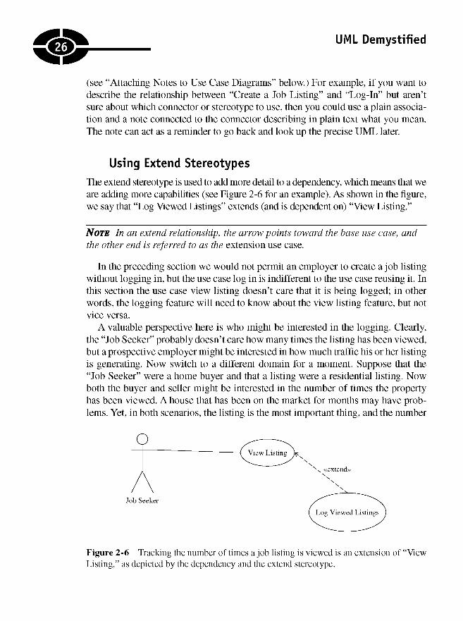
Using Extend Stereotypes
The extend stereotype is used to add more detail to a dependency, which means that weare adding more capabilities (see Figure 2-6 for an example). As shown in the figure,we say that "Log Viewed Listings" extends (and is dependent on) "View Listing."
NOTE In an extend relationship, the arrow points toward the base use case, andthe other end is referred to as the extension use case.
In the preceding section we would not permit an employer to create a job listingwithout logging in, but the use case log in is indifferent to the use case reusing it. Inthis section the use case view listing doesn't care that it is being logged; in otherwords, the logging feature will need to know about the view listing feature, but notvice versa.
A valuable perspective here is who might be interested in the logging. Clearly,the "Job Seeker" probably doesn't care how many times the listing has been viewed,but a prospective employer might be interested in how much traffic his or her listingis generating. Now switch to a different domain for a moment. Suppose that the"Job Seeker" were a home buyer and that a listing were a residential listing. Nowboth the buyer and seller might be interested in the number of times the propertyhas been viewed. A house that has been on the market for months may have prob-lems. Yet, in both scenarios, the listing is the most important thing, and the number
Figure 2-6 Tracking the number of times a job listing is viewed is an extension of "ViewListing," as depicted by the dependency and the extend stereotype.
26

CHAPTER 2 Start at the Beginning with Use Cases
of viewings is secondary. This illustrates the notion of extension use cases as akinto features, and from a marketing perspective, extensions might be items that areseparated into an optional feature pack.
TIP Consider another alternative as relates to an extension use case. Extensionuse cases are natural secondary features. If your project has a tight schedule, dothe extension use cases last, and if you run out of time, then postpone the extensionuse cases to a later version.
Include and extend seem somewhat similar, but the best way to keep them straightis to remember that "the include relationship is intended for reusing behavior mod-eled by another use case, whereas the extend relationship is intended for addingparts to existing use cases as well as for modeling optional system services" (Over-gaard and Palmkvist, 2005, p. 79).
Annotating Use Case Diagrams
Consider the job of a court stenographer. Stenographers use those funny steno-graphic typewriters that produce a sort of shorthand gibberish. We can safely assumethat if a regular typewriter or word processor were capable of accepting input fastenough to keep up with natural speech, then the stenograph would not have beeninvented.
Stenographs produce shorthand that is more condensed than speech. The UMLis like shorthand for code and text, and UML modeling tools are like stenographs.The idea is that models can be created faster than code or faster than writing tex-tual descriptions. That said, sometimes there is no good substitute for text.
If you find yourself in the predicament that only text seems to resolve—or youaren't sure of the UML—then go ahead and add text. You can add text by document-ing your models with features of most modeling tools, by adding URL references tomore verbose documents, or by adding notes directly in the diagrams themselves.However, if you add too much text, then naturally it will take longer for the model-ing to be complete and may require a greater effort to understand the meaning ofindividual diagrams.
Inserting Notes
The UML is a shorthand for a lot of text and code, but if you need to, you can al-ways add text. Every diagram, including use cases, supports adding textualannotations. Notes are represented as a dog-eared piece of paper with a line attach-ing the textbox to the element being annotated (Figure 2-7). Use notes sparinglybecause they can clutter up a diagram and make it harder to read.
27

UML Demystified
Figure 2-7 A note adding plain text to clarify some aspect of a diagram.
Adding Supporting Documentation
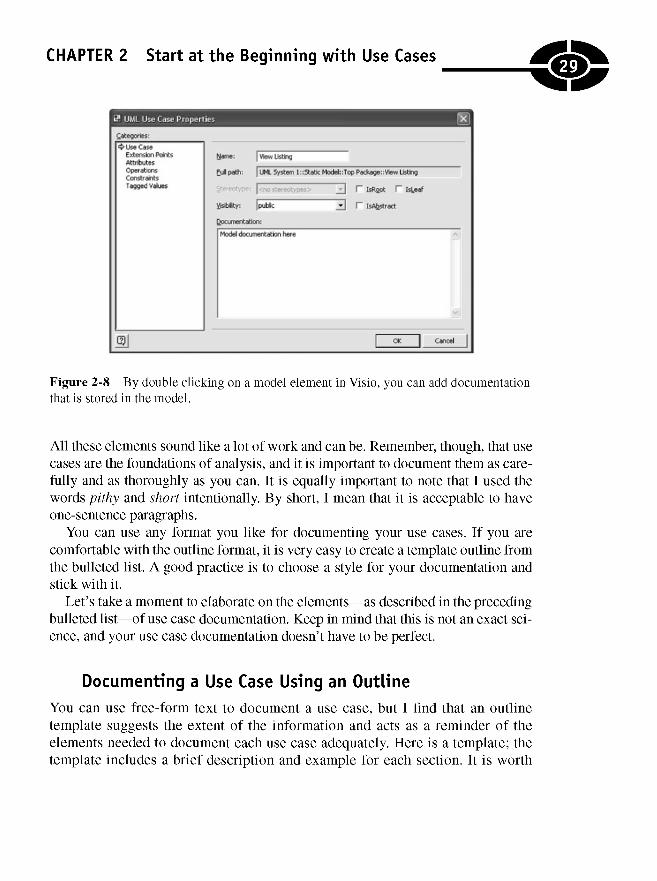
Every modeling tool that I have used—Together, Rose, Rose XDE, Visio, Poseidonfor UML, and the one from Cayenne Software—supports model documentation.This documentation usually takes two forms: text that is stored in the model andUniform Resource Locators (URLs) referencing external documents (Figure 2-8).Exploring the features of your particular tool will uncover these capabilities.
More important is what kind of documentation you should provide. Subjectively,the answer is as little as you can get away with, but use case diagrams generallyseem to need the most.
Use case diagrams are pretty basic with their stick figures but are pretty impor-tant because they record the capabilities your system will have. Good informationto include with your use case diagrams is
• A pithy paragraph describing how the use begins, including any preconditions
• A short paragraph for each of the primary functions
• A short paragraph for each of the secondary functions
• A short paragraph for each of the primary and secondary scenarios, whichhelps to place the need for the functions in a context
• A paragraph for nonfunctional requirements
• Insertion points where any other dependent use cases are used
• An ending point with postconditions
28
CHAPTER 2 Start at the Beginning with Use Cases
Figure 2-8 By double clicking on a model element in Visio, you can add documentationthat is stored in the model.
All these elements sound like a lot of work and can be. Remember, though, that usecases are the foundations of analysis, and it is important to document them as care-fully and as thoroughly as you can. It is equally important to note that I used thewords pithy and short intentionally. By short, I mean that it is acceptable to haveone-sentence paragraphs.
You can use any format you like for documenting your use cases. If you arecomfortable with the outline format, it is very easy to create a template outline fromthe bulleted list. A good practice is to choose a style for your documentation andstick with it.
Let's take a moment to elaborate on the elements—as described in the precedingbulleted list—of use case documentation. Keep in mind that this is not an exact sci-ence, and your use case documentation doesn't have to be perfect.
Documenting a Use Case Using an Outline
You can use free-form text to document a use case, but I find that an outlinetemplate suggests the extent of the information and acts as a reminder of theelements needed to document each use case adequately. Here is a template; thetemplate includes a brief description and example for each section. It is worth
29

UML Demystified
noting that this style of documentation is not part of the UML but is a useful partof modeling.
1. Title
a. Description: Use the use case name here, making it very easy to matchuse case diagrams with their respective documentation.
b. Example: Maintain Job Listing
2. Use case starts
a. Description: Briefly describe the circumstances leading up to the usecase, including preconditions. Leave out implementation details, such as"User Clicks a Hyperlink" or references to forms, controls, or specificimplementation details.
b. Example: This use case starts when an employer, employer's agent, orthe system wants to create, modify, or remove a job listing.
3. Primary functions
a. Description: Use cases are not necessarily singular. For example, "ManageJob Listing" is a reasonable use case and may include primary functionssuch as reading and writing to a repository. The key here is to avoid havingtoo few or too many primary functions. If you need a good yardstick, itmight be two or three primary functions per use case.
b. Example: "CRUD Job Listing." The primary functions of "Maintain JobListing" are to create, read, update, and delete the job listing.
4. Secondary functions
a. Description: Secondary functions are like a supporting cast in a play. Forexample, given a use case "Manage Job Listing," updating, inserting,creating, and deleting a job listing—called CRUD, for create, read,update, and delete—are excellent secondary functions, part of a biggeruse case. If you need a yardstick, then two times as many secondaryfunctions as primary functions is good.
b. Examples:
(1) "Expire Job Listing." Thirty days after the listing is made availablefor viewing, the listing is said to expire. An expired listing is notdeleted, but users, with the exception of the listing owner, may nolonger view the listing.
(2) "Renew Job Listing." A listing may be extended for an additional30 days by paying an additional listing extension fee.
30
CHAPTER 2 Start at the Beginning with Use Cases
(3) "Make Job Listing a Priority Listing." Any time during the life ofa listing, the owner of that listing may elect to promote the listing toa priority listing for a fee prorated by the exhausted portion of thelisting period.
(4) "Log Viewed Listing." Each time a listing is viewed, a log entry willbe written, recording the date and time the listing was viewed andthe Internet Protocol (IP) address of the viewer.
(5) "Examine View Logs." At any time the owner of a listing may viewthe logged information for his or her listings.
(6) "Automatic Viewed-Log Notification." The owner of a job listingmay elect to have view logs sent by e-mail at an interval specified bythe owner.
(7) "Pay for Listing." The owner of the listing is required to pay for everylisting unless the listing is offered as a promotional giveaway.
5. Primary scenarios
a. Description and example: A scenario is a short story that describes thefunctions in a context. For instance, given a primary function "Create JobListing," we might write a scenario such as this: "Mr. Jones' secretaryis retiring, and he needs to hire a replacement. Mr. Jones would likea secretary who types 100 words per minute, is willing to work onlyfour hours per day, and is willing to work for $10 per hour. He needs thereplacement secretary to start no later than January 15." Consider at leastas many primary scenarios as you have primary functions. Also considera couple of scenario variations for important functions. This will helpyou to think about your problem in creative ways. It is a useful practiceto list the scenarios in approximately the same order as the functions thatthe scenario describes.
6. Secondary scenarios
a. Description and example: Secondary scenarios are short stories that putsecondary functions in a context. Consider a secondary scenario we willrefer to as "Expire Job Listing." Demonstrated as a scenario, we mightwrite: "Mr. Jones paid for the listing to run for 30 days. After 30 days,the job listing is delisted, and Mr. Jones is notified by e-mail, providinghim with an opportunity to renew the listing." We can organize thesecondary functions in an ordering consistent with the secondaryfunctions they support.
31
UML Demystified
7. Nonfunctional requirements
a. Description: Nonfunctional requirements address implicit behaviors, suchas how fast something happens or how much data can be transmitted.
b. Example: An employer's payment is to be processed while he or she waitsin a period of time no longer than 60 seconds.
8. Use case ends
a. Description: This part describes what it means for the use case to befinished.
b. Example: The use case is over when changes made to the job listing arepersisted and the payment has been collected.
How much information you include in the written part of your use cases is reallyup to you. The UML is silent on this matter, but a process such as the RUP may of-fer you some guidance on content, quantity, and style of text documentation.
As a final note, it is useful to record ideas about functions and scenarios even ifyou ultimately elect to discard them. For example, we could add a secondary func-tion that states that "The system shall support a semiautomatic renewal of anexpiring job listing" supported by the scenario "Mr. Jones' listing for a new secre-tary is about to expire. Mr. Jones is notified by e-mail of the impending expiration.By clicking on a link in the e-mail, Mr. Jones' listing is automatically renewed us-ing the same billing and payment information used with the original listing."
By recording and keeping considered ideas, it is possible to make a record ofideas that were considered but may or may not ever be realized. Keeping a recordof possibilities prevents you from rehashing ideas as team members come and go.
Finally, it is useful to insert references to depended-on use cases. Rather thanrepeating an inclusion use case, for example, simply make a reference to the inclu-sion use case at the point at which it is needed. For example, suppose that payingfor a job listing requires an employer to log in. Instead of repeating the "Log-In"use case, we simply make a reference to the "Log-In" use case where it is needed;in this instance we can make a reference to "Log-In" when we talk about paying forthe job listing.
Creating Use Case DiagramsAs I mentioned earlier, use cases are design to-do lists. Since another holiday isalways just around the corner, a good comparative analogy is that defining usecases is like writing a list of chores in order to prepare your house for an extended
32
CHAPTER 2 Start at the Beginning with Use Cases
visit from relatives. For example, you might write down, "Dust living room." Thenyou decide that your 10-year-old daughter did a good job the last time, so you as-sign the dusting to her. The level of detail is important here because you know—ifyou have ever dusted—that different kinds of things need different kinds of dusting.Small knickknacks can be dusted with a feather duster. Coffee tables and end tablesmight need Pledge® and a clean, dry, cloth, and ceiling fans might need the wandand brush on a vacuum cleaner. The key here is the difference between what wediagram and what we write as part of our use case.
NOTE You might wonder what dusting has to do with use cases and software.The first answer is that use case models can be used for things that aren't software,and the second part is that software is found in an increasingly larger number ofdevices. Suppose that we were defining use cases for a house-cleaning robot; thenour dusting rules might be useful. And if you are wondering how probable softwarefor robots might be, then consider the Roomba* cleaner. Roomba is a small robotthat wanders around a room vacuuming up debris, and according to its marketingmaterial, it even knows when to recharge itself. Someone had to define and implementthose capabilities.
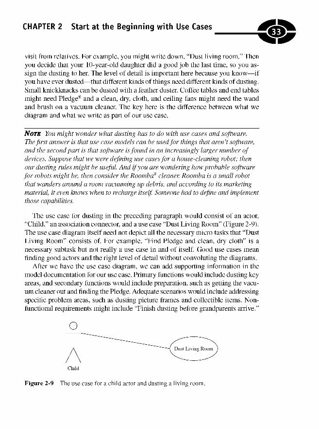
The use case for dusting in the preceding paragraph would consist of an actor,"Child," an association connector, and a use case "Dust Living Room" (Figure 2-9).The use case diagram itself need not depict all the necessary micro tasks that "DustLiving Room" consists of. For example, "Find Pledge and clean, dry cloth" is anecessary subtask but not really a use case in and of itself. Good use cases meanfinding good actors and the right level of detail without convoluting the diagrams.
After we have the use case diagram, we can add supporting information in themodel documentation for our use case. Primary functions would include dusting keyareas, and secondary functions would include preparation, such as getting the vacu-um cleaner out and finding the Pledge. Adequate scenarios would include addressingspecific problem areas, such as dusting picture frames and collectible items. Non-functional requirements might include "Finish dusting before grandparents arrive."
Figure 2-9 The use case for a child actor and dusting a living room.
33
UML Demystified
Don't worry about perfect use case diagrams and use case documentation. Use theoutline to help you consider the details and use case diagrams to provide you witha good picture of your objectives.
How Many Diagrams Is Enough?
Sufficiency is a tricky problem. If you provide too many use cases, your modelingcan go on for months or even years. You can run into the same problem with usecase documentation, too.
NOTE I consulted on a project for a large department of defense agency. Theagency literally had been working on use cases for almost 2 years with no end insight. Aside from what seemed like a never-ending project, the domain experts feltthat the wrong use cases were being captured or that the use cases had little or noexplanatory, practical value. The models were missing the mark. The objective is tocapture the essential characteristics of your objective, and use case models are anexcellent low-tech way to get nontechnical domain experts involved. Skipping thedialogue-provoking value of use case diagrams is missing half the value of the usecase diagrams.
A reasonable baseline is that medium-complexity applications might have be-tween 20 and 50 good use cases. If you know that your problem is moderatelycomplex and you have five use cases, then you may be missing critical functionality.On the other hand, if you have hundreds of use cases, then you may be subdividingpractical macro use cases into micro use cases.
Unfortunately, there are no hard and fast rules. Defining the right use cases takespractice and requires good judgment that is acquired over time. To help you beginacquiring some experience, the next subsection demonstrates some actual use casediagrams for www.motown-jobs.com.
Example Use Case Diagrams
This book is about the UML. Specific text documentation is not part of the UML,so I will limit the examples in this section to creating the use case diagrams. Youcan use your imagination and the outline in the section entitled "Documentinga Use Case Using an Outline" to practice writing use case descriptions.
Motown-jobs.com is a product of my company, Software Conceptions, Inc.Motown-jobs is a Web site for matching people looking for jobs with people offeringjobs. It is a Web site like dice.com, monster.com, computerjobs.com, or hotjobs.com
34

CHAPTER 2 Start at the Beginning with Use Cases
and is implemented in ASP.NET. All this aside, Motown-jobs.com started as anidea whose features were captured as a group of use cases. Because I was buildingthe software for my company, I had to play the role of domain expert—the domainbeing what it takes to match employers with employees. Since I have been lookingfor and finding customers for my company for 15 years, I have some experience inthis area.
Finding use cases can start with an interview with your domain expert or bymaking a list. Since I was playing the role of interviewer and interviewee, I simplybegan with a list of the things I thought Motown-jobs.com would need to offer to beuseful. Here is my list:
• Employers or employers' agents will want to post information about jobsbeing offered.
• Those looking for jobs may want to post a resume that can be viewed bypotential employers.
• Employers or employers' agents will want to actively search the Web sitefor resumes that match the skills needed to fill job openings.
• Those looking for jobs will want to search through jobs listed.
• Employers and employers' agents will have to pay for listings and forsearching for resumes, but posting resumes or searching through jobs willbe a free service.
• An additional source of revenue might be advertising and resume-buildingservices, so the Web site will be able to sell and post advertising space andhelp job seekers create resumes.
In addition to software being expensive to write and hardware, server software,and high-speed Internet connections being expensive to purchase and maintain,helping businesses find employees is a valuable service—or at least that is thepremise behind building Motown-jobs.com in the first place. Figuring out howmuch to charge for the listings and attracting advertisers are business and marketingfunctions, so I won't talk about that in my list of use cases.
Now, clearly, I could get stuck examining all the little tasks that each of themacro tasks—such as posting job vacancies—consists of, but the list I have is a verygood starting place. Let's start by diagramming these features (Figure 2-10).
Notice in the Figure 2-10 that I captured maintaining jobs and finding resumesfor employer types, maintaining advertisements for advertiser types, posting resu-mes and finding jobs for job seeker types, and managing billing for the system. Thenext thing I can do is ask involved parties if these use cases capture the essence ofthe features I need.
35
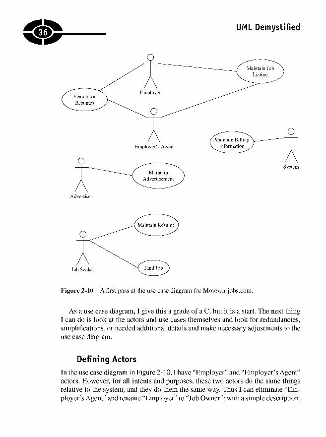
UML Demystified
Figure 2-10 A first pass at the use case diagram for Motown-jobs.com.
As a use case diagram, I give this a grade of a C, but it is a start. The next thingI can do is look at the actors and use cases themselves and look for redundancies,simplifications, or needed additional details and make necessary adjustments to theuse case diagram.
Defining Actors
In the use case diagram in Figure 2-10,1 have "Employer" and "Employer's Agent"actors. However, for all intents and purposes, these two actors do the same thingsrelative to the system, and they do them the same way. Thus I can eliminate "Em-ployer's Agent" and rename "Employer" to "Job Owner"; with a simple description,
36

CHAPTER 2 Start at the Beginning with Use Cases
"Job Owner" captures the idea that a listed job is "owned" by a responsible party.Figure 2-11 shows the revision in the use case diagram.
Next, it seems pretty obvious that a job listing, a resume, and an advertisementare all kinds of listings, and the people who own those elements are "Listing Own-ers." I can experiment with these relationships using generalization. The modifieduse case diagram is shown in Figure 2-12.
Figure 2-12 treats jobs, advertisements, and resumes all as listings that need tobe maintained. It also shows that the billing system is associated with listings andresume searches. In some ways Figure 2-12 is an improvement, but in others it istoo clever. For example, depicting a job seeker as a "Listing Owner" suggests thatevery job seeker owns a listed resume. What if a job seeker doesn't want to post
Figure 2-11 "Employer" and "Employer's Agent" are converted to a single actor, "JobOwner."
37

38UML Demystified
Figure 2-12 This figure suggests that jobs, resumes, and advertisements are all listingsthat have to be maintained by a listing owner, as well as associations between the billingsystem and listings and resume searches.
a resume? Further, I said that posting a resume is a free service, but the implicationis that the billing system treats resume listings as a billable item. Does this meanthat it is billable but costs $0? The revised diagram seems a bit clever and raises asmany questions as it answers. Perhaps I could further divide "Listings" into "Bill-able Listings" and "Free Listings." This might resolve the billing system question,but what about job seekers who don't post resumes? I still have to resolve this issue.For now, I go back to four separate actors as opposed to three kinds of listing own-ers and the system actor (Figure 2-13).
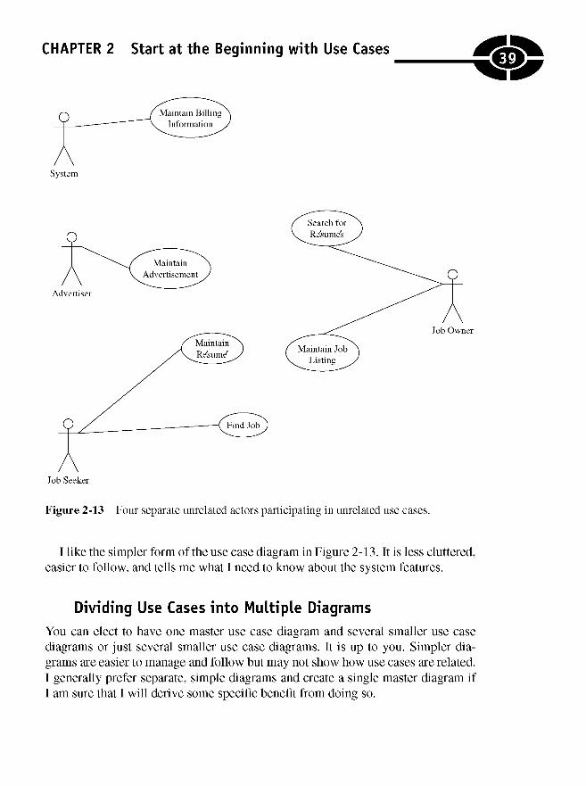
CHAPTER 2 Start at the Beginning with Use Cases
Figure 2-13 Four separate unrelated actors participating in unrelated use cases.
I like the simpler form of the use case diagram in Figure 2-13. It is less cluttered,easier to follow, and tells me what I need to know about the system features.
Dividing Use Cases into Multiple Diagrams
You can elect to have one master use case diagram and several smaller use casediagrams or just several smaller use case diagrams. It is up to you. Simpler dia-grams are easier to manage and follow but may not show how use cases are related.I generally prefer separate, simple diagrams and create a single master diagram ifI am sure that I will derive some specific benefit from doing so.
39
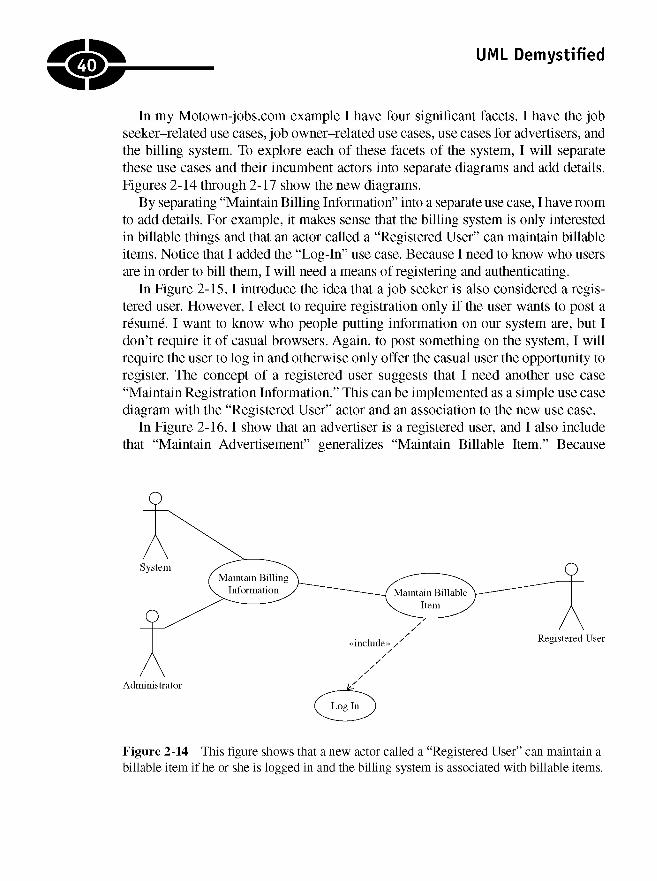
UML Demystified
In my Motown-jobs.com example I have four significant facets. I have the jobseeker-related use cases, job owner-related use cases, use cases for advertisers, andthe billing system. To explore each of these facets of the system, I will separatethese use cases and their incumbent actors into separate diagrams and add details.Figures 2-14 through 2-17 show the new diagrams.
By separating "Maintain Billing Information" into a separate use case, I have roomto add details. For example, it makes sense that the billing system is only interestedin billable things and that an actor called a "Registered User" can maintain billableitems. Notice that I added the "Log-In" use case. Because I need to know who usersare in order to bill them, I will need a means of registering and authenticating.
In Figure 2-15,1 introduce the idea that a job seeker is also considered a regis-tered user. However, I elect to require registration only if the user wants to post aresume. I want to know who people putting information on our system are, but Idon't require it of casual browsers. Again, to post something on the system, I willrequire the user to log in and otherwise only offer the casual user the opportunity toregister. The concept of a registered user suggests that I need another use case"Maintain Registration Information." This can be implemented as a simple use casediagram with the "Registered User" actor and an association to the new use case.
In Figure 2-16,1 show that an advertiser is a registered user, and I also includethat "Maintain Advertisement" generalizes "Maintain Billable Item." Because
Figure 2-14 This figure shows that a new actor called a "Registered User" can maintain abillable item if he or she is logged in and the billing system is associated with billable items.
40
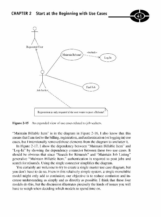
CHAPTER 2 Start at the Beginning with Use Cases
Figure 2-15 An expanded view of use cases related to job seekers.
"Maintain Billable Item" is in the diagram in Figure 2-16, I also know that thismeans that I am tied to the billing, registration, and authentication (or logging in) usecases, but I intentionally removed those elements from the diagram to unclutter it.
In Figure 2-17, I show the dependency between "Maintain Billable Item" and"Log-In" by showing the dependency connector between these two use cases. Itshould be obvious that since "Search for Resumes" and "Maintain Job Listing"generalize "Maintain Billable Item," authentication is required to post jobs andsearch for resumes. Using the single connector simplifies the diagram.
You certainly are welcome to try to create a single master use case diagram, butyou don't have to do so. Even in this relatively simple system, a single monolithicmodel might only add to confusion; our objective is to reduce confusion and in-crease understanding as simply and as directly as possible. I think that these fourmodels do this, but the discussion illustrates precisely the kinds of issues you willhave to weigh when deciding which models to spend time on.
41
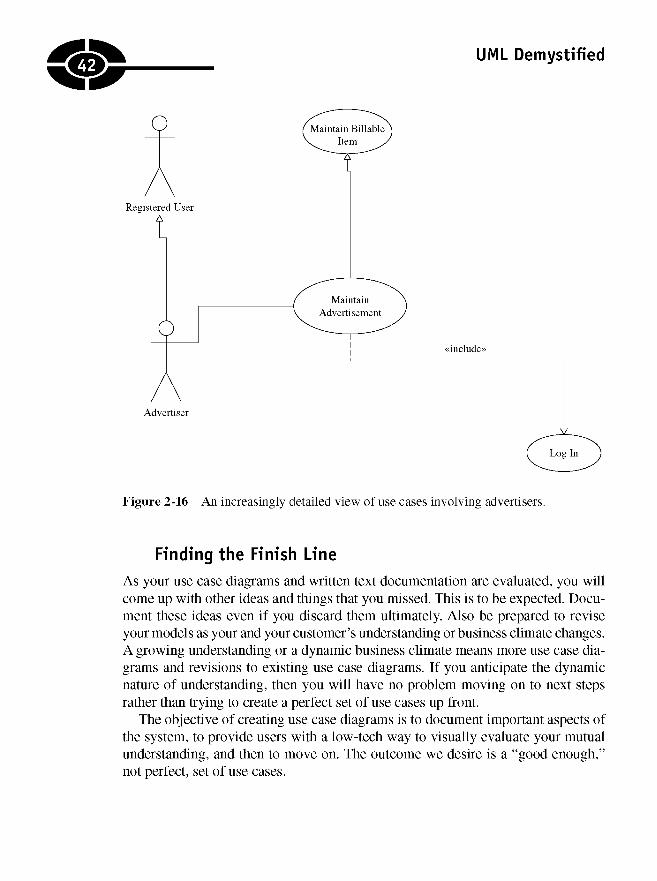
UML Demystified
Figure 2-16 An increasingly detailed view of use cases involving advertisers.
Finding the Finish Line
As your use case diagrams and written text documentation are evaluated, you willcome up with other ideas and things that you missed. This is to be expected. Docu-ment these ideas even if you discard them ultimately. Also be prepared to reviseyour models as your and your customer's understanding or business climate changes.A growing understanding or a dynamic business climate means more use case dia-grams and revisions to existing use case diagrams. If you anticipate the dynamicnature of understanding, then you will have no problem moving on to next stepsrather than trying to create a perfect set of use cases up front.
The objective of creating use case diagrams is to document important aspects ofthe system, to provide users with a low-tech way to visually evaluate your mutualunderstanding, and then to move on. The outcome we desire is a "good enough,"not perfect, set of use cases.
42
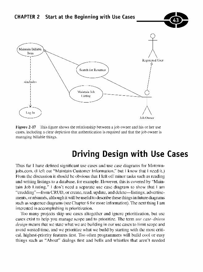
CHAPTER 2 Start at the Beginning with Use Cases
Figure 2-17 This figure shows the relationship between a job owner and his or her usecases, including a clear depiction that authentication is required and that the job owner ismanaging tollable things.
Driving Design with Use CasesThus far I have defined significant use cases and use case diagrams for Motown-jobs.com. (I left out "Maintain Customer Information," but I know that I need it.)From the discussion it should be obvious that I left off minor tasks such as readingand writing listings to a database, for example. However, this is covered by "Main-tain Job Listing." I don't need a separate use case diagram to show that I am"crudding"—from CRUD, or create, read, update, and delete—listings, advertise-ments, or resumes, although it will be useful to describe these things in future diagramssuch as sequence diagrams (see Chapter 6 for more information). The next thing I aminterested in accomplishing is prioritization.
Too many projects skip use cases altogether and ignore prioritization, but usecases exist to help you manage scope and to prioritize. The term use case-drivendesign means that we state what we are building in our use cases to limit scope andavoid wasted time, and we prioritize what we build by starting with the most criti-cal, highest-priority features first. Too often programmers will build cool or easythings such as "About" dialogs first and bells and whistles that aren't needed
43

UML Demystified
because they are exploring some new technology, and this is a significant factor inwhy so many projects fail.
After you have defined your use cases, you will want to prioritize and furtherdesign and implement a solution to support those use cases that have the highestpriority or represent the most significant risk. How do you decide what to designand build first? The answer is to ask you customer what is most risky, most impor-tant, or most valuable and then to focus your energies on those use cases.
NOTE The real question to ask your customers is: "What features can we buildfirst so that if we run out of time and money, we still will have a marketableproduct? Customers don't always want to hear the tough questions, and you willhave to exercise some diplomacy, but finding the right answer to this question andacting on it may be the most important thing you do.
For Motown-jobs.com, I decided—as the customer—that I can go to market witha fee-based job listing service. This means that if I implement "Maintain Job Listing,""Search for a Job," and "Maintain Billing Information," I will have a product that Ican go to market with. This doesn't mean that I won't build resume posting, search-ing, and advertising support into the system—it just means that these aren't themost important features.
Next priorities are tougher. Should I build resume posting and searching or ad-vertising next? The answer is that I want job seekers to use the service and jobowners to see that there is a lot of traffic on and interest in my site, so I will supportposting a resume next—which is a free service but critical—and then resumesearching—which is also a fee service but dependent on having resumes to lookthrough. Finally, I will support advertising, which ultimately is dependent on hav-ing enough traffic to interest advertisers.
The important thing here is that identifying my use cases helped me prioritizemy list of tasks and illustrates a critical path to my minimal-success criterion—selling help wanted advertisements.
Quiz1. What symbol represents a use case?
a. Aline
b. A directed line
c. A stick figure
d. An oval containing text
44

CHAPTER 2 Start at the Beginning with Use Cases
2. An actor can only be a person.
a. True
b. False
3. What symbol represents a dependency?
a. Aline
b. A line with a triangle pointing toward the dependent element
c. A dashed line with an arrow pointing toward the dependent element
d. A dashed line with an arrow pointing toward the depended-on element
4. How is a stereotype indicated on a connector?
a. Text between a pair of guillemots
b. Plain text next to the connector
c. The word stereotype inside of the oval symbol
5. An inclusion relationship is used for reusing behavior modeled by anotheruser case.
a. True
b. False
6. An extension relationship is used for modeling optional system features.
a. True
b. False
7. Generalization in the UML is reflected in implementation by
a. polymorphism.
b. aggregation.
c. inheritance.
d. interfaces.
8. Every capability of a system should be represented by a use case.
a. True
b. False
9. In an extend relationship, the arrow points toward the
a. base use case.
b. extension use case.
45
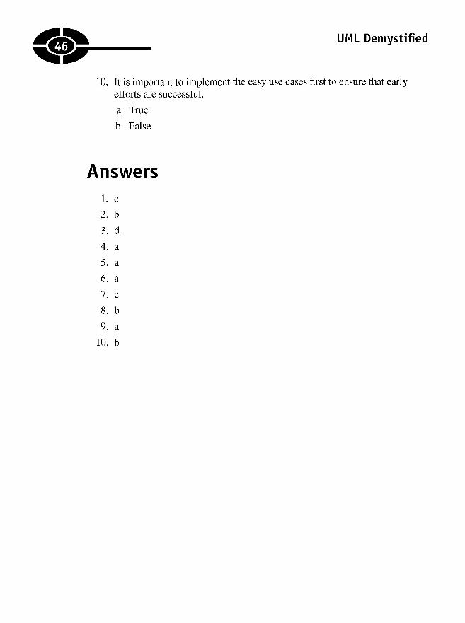
UML Demystified
10. It is important to implement the easy use cases first to ensure that earlyefforts are successful.
a. True
b. False
Answers1. c
2. b
3. d
4. a
5. a
6. a
7. c
8. b
9. a
10. b
46
CHAPTER
DiagrammingFeatures as
Processes
This chapter is about activity diagrams. While my emphasis isn't process, a nextstep after capturing use cases is to begin describing how the features represented byyour use cases will play out. Activity diagrams help you and users to describe visu-ally the sequence of actions that leads you through the completion of a task.
The goal is to converge on code continuously by starting with an understanding ofthe problem space in general and capturing the problems we will solve—use cases—by describing how those features work and ultimately implementing the solution.Activity diagrams are a useful analysis tool and can be used for process reengineer-ing, i.e., redesigning process. In this way, activity diagrams are a progressive
47
3
Copyright © 2005 by The McGraw-Hill Companies. Click here for terms of use.
UML Demystified
bridge leading from analysis to design and ultimately to implementation. In thischapter you will learn about
• The symbols used to create activity diagrams
• How to create activity diagrams by describing use cases and scenarios as aseries of actions
• Modeling simultaneous behaviors
• Refining physical activities with activity diagrams
• Figuring out when to stop creating activity diagrams
Elaborating on Features as ProcessesFew ideas are completely new. Existing concepts are refined and evolve and mature,carrying along some of the old and some of the new. The same is true for analysisand design concepts.
Structured analysis and design emphasized the flowchart. An activity diagram inthe Unified Modeling Language (UML) is pretty close to a flowchart. The symbolsare similar but not the same. The utility is similar, but there is a difference. Activitydiagrams, unlike flowcharts, can model parallel behavior.
Activity diagrams are good analysis diagrams for developers, users, testers, andmanagers because they use simple symbols, plain text, and a style that is similar to thefamiliar flowchart. Activity diagrams are good at helping you to capture, visualize, anddescribe an ordered set of actions from a beginning to an end. Activity diagrams arecreated as a finite set of serial actions or a combination of serial and parallel actions.
A Journey toward CodeA basic principle of objected-oriented analysis and design is that we want to startfrom high-level problem-space ideas and concepts and move toward a low-levelsolution space. The high-level problem space is also referred to as the problem do-main. The low-level solution space is referred to as the solution domain. The UMLis a language for capturing and describing our understanding as we move fromdocumenting a problem to coding a solution.
Based on the idea of moving our understanding from concept to design, use casesare a good way to capture the things that describe our problem. For example, we wantto match employers to potential employees by providing a job listing board. A usecase that supports this is to manage listings. A next step in an abstract sense is todescribe how we would go about managing a listing. At this juncture it is still too early
48

CHAPTER 3 Diagramming Features as Processes
to begin talking about databases and programming languages. Instead, we want to talkabout the activities that describe our problem, and these activities consist of actions.
NOTE At an ideological level, analysis and design are processes whereby wedecompose a problem into smaller discrete problems so that we can compose smallsolutions for each discrete problem and ultimately orchestrate the small solutionsinto a coherent whole. The UML is a language for decomposing a problem andrecomposing it as the description of a solution. A language such as Visual Basic.NETis useful for implementing the solution description, and process is how we go about it.
Understanding Activity Diagram UsesActivity diagrams are not really about methods or classes. It is still too early forthat. The reason that it is too early is because technical things such as polymor-phism, inheritance, methods, and attributes generally are meaningless concepts tousers and sometimes managers.
Activity diagrams are a means by which we can capture the understanding ofpeople we call domain experts. For example, if you are building a jail-managementsystem, then a domain expert might be a corrections officer. A corrections officerprobably won't understand the difference between a namespace, class, and inter-face, but as a designer, you may not understand the significance of a purchase of50 toothbrushes by an inmate. An activity diagram can help.
A true story—and why consulting can be interesting—is behind the toothbrushmetaphor. While working for a large county jail system in Oregon, I had to writea pilot application to demonstrate ASP.NET in its early days. The pilot ultimatelywould be part of an inmate account-management system for the jail. The basic ideawas that prisoners can't be in possession of cash, but they can have money on ac-count to purchase personal items and snacks. The county managed the accounts.Some of the rules included limits on the number of candy bars, say, a diabetic mightpurchase, as well as a limit on the number of toothbrushes that could be purchased.Not being a corrections officer, it seemed weird to me that anyone would buy morethan one toothbrush and weirder still why anyone would care. The problem is thatwhen scraped to a sharp point or split with a piece of a safety razorblade wedgedinto the split and held in place by a rubber band, a toothbrush can become a formi-dable weapon. (In reality, I knew this because I either learned it as a militarypoliceman or saw it on an episode of "Oz" on HBO.)
In practice, this story is illustrative of the fact that those on the ground—the do-main experts—will know details that you will never think of. Activity diagrams aregood for capturing these details in a general sense and in a way that the domainexperts can examine, clarify, and improve on.
49

UML Demystified
Working backward from my prisoner account-management story, we might have ause case "Make Purchase" and a scenario in that use case that we need to ensure that thepurchase does not violate a safety rule. We can capture this in an activity diagram plainlyenough that a corrections officer can tell us if we understand the problem and have de-composed it sufficiently. Figure 3-1 shows an activity diagram for this scenario.
Figure 3-1 An activity diagram that illustrates restrictions on the kind and number ofitems that can be purchased in prison.
50
CHAPTER 3 Diagramming Features as Processes
For now, don't worry about what the shapes mean. Simply note the simple textand the flow suggested by the arrows. The general idea is that at a glance—perhapswith a minimum of explanation—this diagram should make sense to users and de-velopers alike. The next section will begin exploring what all these elements andmore mean.
Using Activity Diagram SymbolsActivity diagrams can be simple flowcharts that have a finite beginning and endingpoint or more complex diagrams that model parallel behavior and multiple subflowsand define multiple terminuses. I find that diagramming simple activities is an excel-lent way to get started and that adding too many alternate scenarios in a single diagrammakes it both hard to manage and print the diagram and difficult to understand.
Making your activity diagrams comprehensible may be more important than mak-ing the diagram comprehensive or all-encompassing. Another mistake is to createactivity diagrams for every use case and scenario. Creating diagrams is time-consuming,and a good way to focus your time is by diagramming those aspects that are morecritical to solving your problem.
Consider a couple of examples. Programs that store data commonly do so in re-lational databases. This behavior is called create, read, update, and delete (CRUD)behavior. Reading and writing data from a database are so well understood that Iwouldn't diagram this behavior as a separate activity. (In fact, the notion of a data-base really shouldn't show up in an activity diagram.) The entire read-write behaviormight be captured at some point in an activity as an action called fetch and store orread and write. On the other hand—borrowing from Chapter 2—if we are going toexpire a customer's job listing and want to give that customer an opportunity to ex-tend the job listing, then this is less common than CRUD behavior, and I wouldcreate an activity diagram to explore the sequence of actions. By diagramming the"Expire Listing" activity, I could get the sequence of actions just right, and it mightbe the catalyst for improving on the quality of service. For example, we might comeup with the renew by e-mail feature we discussed in Chapter 2.
If you have created some flowcharts with a tool such as Visio in the past, then activ-ity diagrams will seem pretty straightforward, but keep in mind that activity diagramscan be used to model richer behavior than plain old flowcharts. In order to create ac-tivity diagrams, you will need to learn abut the symbols and rules that apply.
TIP You can think of the symbols and rules of any UML diagram as the visualgrammar for the language.
51
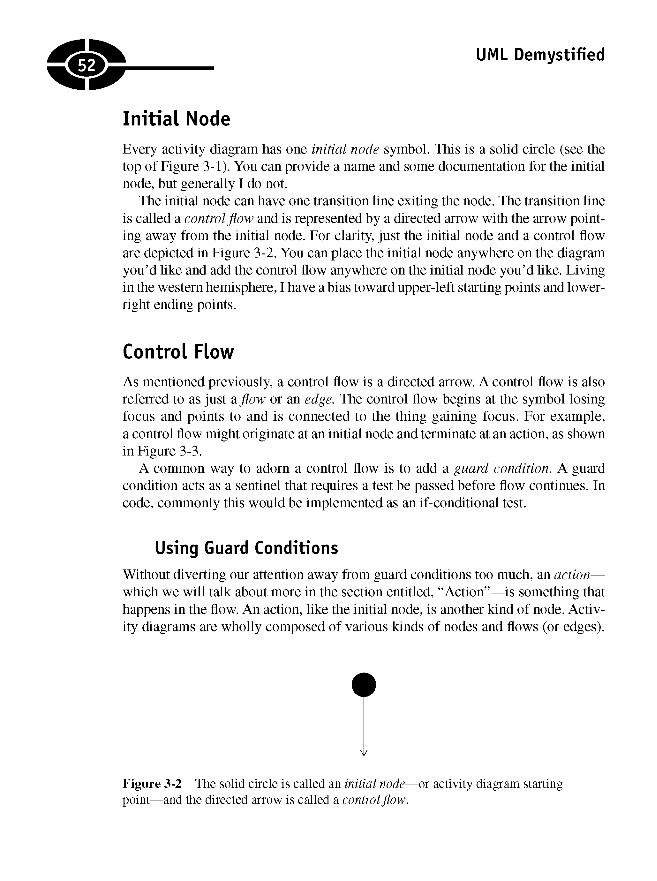
UML Demystified
Initial NodeEvery activity diagram has one initial node symbol. This is a solid circle (see thetop of Figure 3-1). You can provide a name and some documentation for the initialnode, but generally I do not.
The initial node can have one transition line exiting the node. The transition lineis called a control flow and is represented by a directed arrow with the arrow point-ing away from the initial node. For clarity, just the initial node and a control floware depicted in Figure 3-2. You can place the initial node anywhere on the diagramyou'd like and add the control flow anywhere on the initial node you'd like. Livingin the western hemisphere, I have a bias toward upper-left starting points and lower-right ending points.
Control FlowAs mentioned previously, a control flow is a directed arrow. A control flow is alsoreferred to as just a flow or an edge. The control flow begins at the symbol losingfocus and points to and is connected to the thing gaining focus. For example,a control flow might originate at an initial node and terminate at an action, as shownin Figure 3-3.
A common way to adorn a control flow is to add a guard condition. A guardcondition acts as a sentinel that requires a test be passed before flow continues. Incode, commonly this would be implemented as an if-conditional test.
Using Guard Conditions
Without diverting our attention away from guard conditions too much, an action—which we will talk about more in the section entitled, "Action"—is something thathappens in the flow. An action, like the initial node, is another kind of node. Activ-ity diagrams are wholly composed of various kinds of nodes and flows (or edges).
Figure 3-2 The solid circle is called an initial node—or activity diagram startingpoint—and the directed arrow is called a control flow.
52
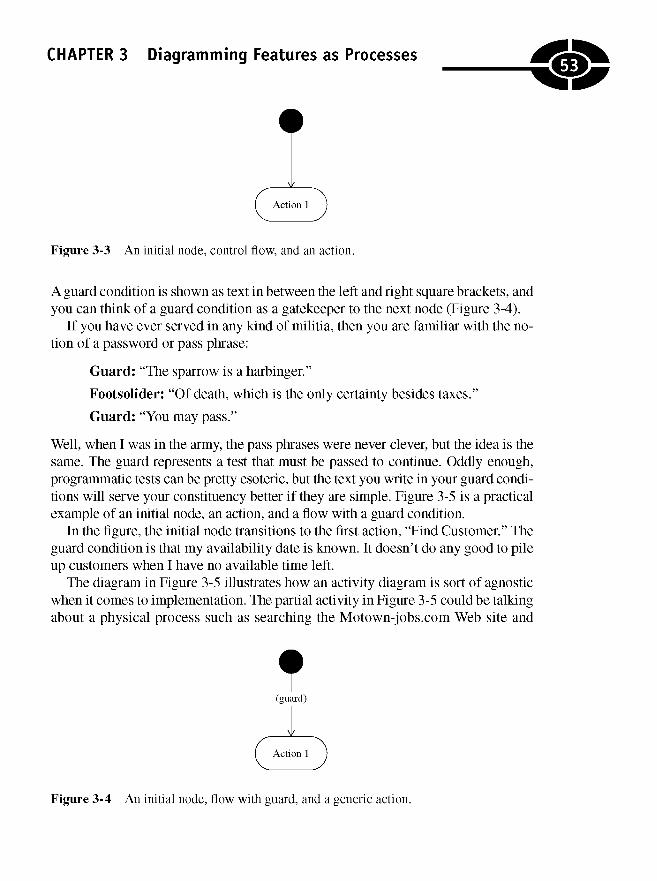
CHAPTER 3 Diagramming Features as Processes
Figure 3-3 An initial node, control flow, and an action.
A guard condition is shown as text in between the left and right square brackets, andyou can think of a guard condition as a gatekeeper to the next node (Figure 3-4).
If you have ever served in any kind of militia, then you are familiar with the no-tion of a password or pass phrase:
Guard: "The sparrow is a harbinger."
Footsolider: "Of death, which is the only certainty besides taxes."
Guard: "You may pass."
Well, when I was in the army, the pass phrases were never clever, but the idea is thesame. The guard represents a test that must be passed to continue. Oddly enough,programmatic tests can be pretty esoteric, but the text you write in your guard condi-tions will serve your constituency better if they are simple. Figure 3-5 is a practicalexample of an initial node, an action, and a flow with a guard condition.
In the figure, the initial node transitions to the first action, "Find Customer." Theguard condition is that my availability date is known. It doesn't do any good to pileup customers when I have no available time left.
The diagram in Figure 3-5 illustrates how an activity diagram is sort of agnosticwhen it comes to implementation. The partial activity in Figure 3-5 could be talkingabout a physical process such as searching the Motown-jobs.com Web site and
Figure 3-4 An initial node, flow with guard, and a generic action.
53
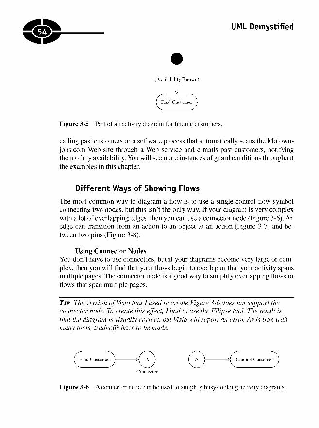
UML Demystified
Figure 3-5 Part of an activity diagram for finding customers.
calling past customers or a software process that automatically scans the Motown-jobs.com Web site through a Web service and e-mails past customers, notifyingthem of my availability. You will see more instances of guard conditions throughoutthe examples in this chapter.
Different Ways of Showing Flows
The most common way to diagram a flow is to use a single control flow symbolconnecting two nodes, but this isn't the only way. If your diagram is very complexwith a lot of overlapping edges, then you can use a connector node (Figure 3-6). Anedge can transition from an action to an object to an action (Figure 3-7) and be-tween two pins (Figure 3-8).
Using Connector NodesYou don't have to use connectors, but if your diagrams become very large or com-plex, then you will find that your flows begin to overlap or that your activity spansmultiple pages. The connector node is a good way to simplify overlapping flows orflows that span multiple pages.
TIP The version of Visio that I used to create Figure 3-6 does not support theconnector node. To create this effect, I had to use the Ellipse tool. The result isthat the diagram is visually correct, but Visio will report an error. As is true withmany tools, tradeoffs have to be made.
Figure 3-6 A connector node can be used to simplify busy-looking activity diagrams.
54
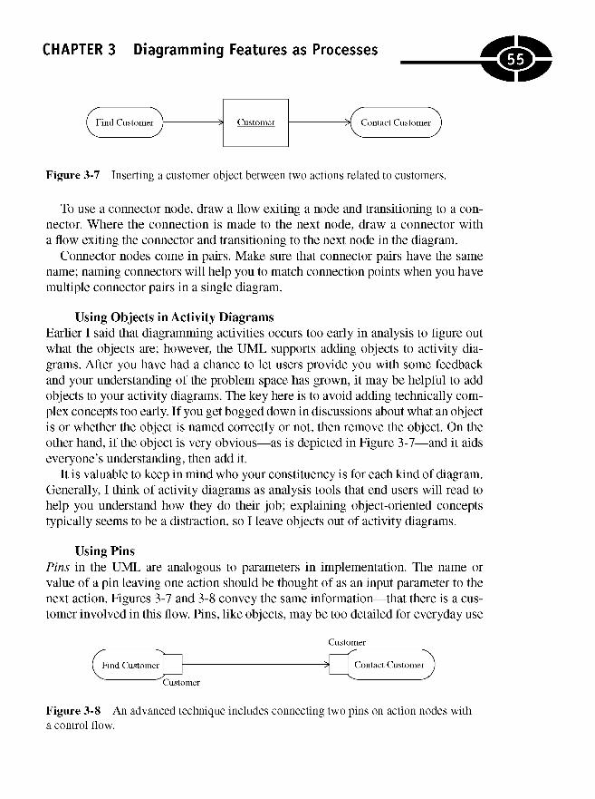
CHAPTER 3 Diagramming Features as Processes
Figure 3-7 Inserting a customer object between two actions related to customers.
To use a connector node, draw a flow exiting a node and transitioning to a con-nector. Where the connection is made to the next node, draw a connector witha flow exiting the connector and transitioning to the next node in the diagram.
Connector nodes come in pairs. Make sure that connector pairs have the samename; naming connectors will help you to match connection points when you havemultiple connector pairs in a single diagram.
Using Objects in Activity DiagramsEarlier I said that diagramming activities occurs too early in analysis to figure outwhat the objects are; however, the UML supports adding objects to activity dia-grams. After you have had a chance to let users provide you with some feedbackand your understanding of the problem space has grown, it may be helpful to addobjects to your activity diagrams. The key here is to avoid adding technically com-plex concepts too early. If you get bogged down in discussions about what an objectis or whether the object is named correctly or not, then remove the object. On theother hand, if the object is very obvious—as is depicted in Figure 3-7—and it aidseveryone's understanding, then add it.
It is valuable to keep in mind who your constituency is for each kind of diagram.Generally, I think of activity diagrams as analysis tools that end users will read tohelp you understand how they do their job; explaining object-oriented conceptstypically seems to be a distraction, so I leave objects out of activity diagrams.
Using PinsPins in the UML are analogous to parameters in implementation. The name orvalue of a pin leaving one action should be thought of as an input parameter to thenext action. Figures 3-7 and 3-8 convey the same information—that there is a cus-tomer involved in this flow. Pins, like objects, may be too detailed for everyday use
Figure 3-8 An advanced technique includes connecting two pins on action nodes witha control flow.
55
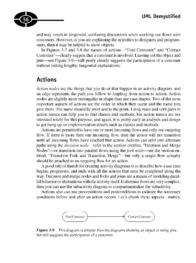
UML Demystified
and may result in tangential, confusing discussions when working out flows withcustomers. However, if you are explaining the activities to designers and program-mers, then it may be helpful to show objects.
In Figures 3-7 and 3-8 the names of actions—"Find Customer" and "ContactCustomer"—clearly suggest that a customer is involved. Leaving out the object andpins—see Figure 3-9—still pretty clearly suggests the participation of a customerwithout risking lengthy, tangential explanations.
Actions
Action nodes are the things that you do or that happen in an activity diagram, andan edge represents the path you follow to leapfrog from action to action. Actionnodes are slightly more rectangular in shape than use case shapes. Two of the mostimportant aspects of actions are the order in which they occur and the name yougive them. The name should be short and to the point. Using noun and verb pairs inaction names can help you to find classes and methods, but action names are notintended solely for this purpose, and again, it is pretty early in analysis and designto get hung up on implementation details such as classes and methods.
Actions are permitted to have one or more incoming flows and only one outgoingflow. If there is more then one incoming flow, then the action will not transitionuntil all incoming flows have reached that action. Actions can split into alternatepaths using the decision node—refer to the section entitled, "Decision and MergeNodes"—or transition into parallel flows using the/orfc node—see the section en-titled, "Transition Fork and Transition Merge"—but only a single flow actuallyshould be attached as an outgoing flow for an action.
A good rule of thumb for creating activity diagrams is to describe how a use casebegins, progresses, and ends with all the actions that must be completed along theway. Decision and merge nodes and forks and joins are a means of modeling paral-lel behavior or alternations with the activity itself. If alternate flows are very complex,then you can use the subactivity diagram to compartmentalize the subactivity.
Actions also can use preconditions and postconditions to indicate the necessaryconditions before and after an action occurs. Let's chunk these aspects—names,
Figure 3-9 This diagram is simpler than the diagrams showing an object or using pinsbut still suggests the participation of a customer.
56
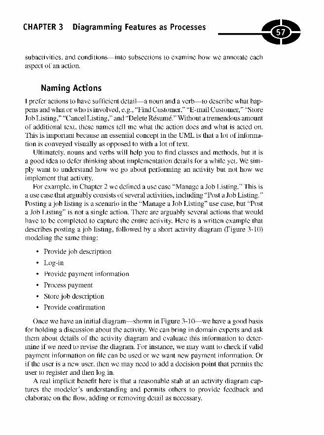
CHAPTER 3 Diagramming Features as Processes
subactivities, and conditions—into subsections to examine how we annotate eachaspect of an action.
Naming Actions
I prefer actions to have sufficient detail—a noun and a verb—to describe what hap-pens and what or who is involved, e.g., "Find Customer," "E-mail Customer," "StoreJob Listing," "Cancel Listing," and "Delete Resume." Without a tremendous amountof additional text, these names tell me what the action does and what is acted on.This is important because an essential concept in the UML is that a lot of informa-tion is conveyed visually as opposed to with a lot of text.
Ultimately, nouns and verbs will help you to find classes and methods, but it isa good idea to defer thinking about implementation details for a while yet. We sim-ply want to understand how we go about performing an activity but not how weimplement that activity.
For example, in Chapter 2 we defined a use case "Manage a Job Listing." This isa use case that arguably consists of several activities, including "Post a Job Listing."Posting a job listing is a scenario in the "Manage a Job Listing" use case, but "Posta Job Listing" is not a single action. There are arguably several actions that wouldhave to be completed to capture the entire activity. Here is a written example thatdescribes posting a job listing, followed by a short activity diagram (Figure 3-10)modeling the same thing:
• Pro vide job description
• Log-in
• Provide payment information
• Process payment
• Store job description
• Provide confirmation
Once we have an initial diagram—shown in Figure 3-10—we have a good basisfor holding a discussion about the activity. We can bring in domain experts and askthem about details of the activity diagram and evaluate this information to deter-mine if we need to revise the diagram. For instance, we may want to check if validpayment information on file can be used or we want new payment information. Orif the user is a new user, then we may need to add a decision point that permits theuser to register and then log in.
A real implicit benefit here is that a reasonable stab at an activity diagram cap-tures the modeler's understanding and permits others to provide feedback andelaborate on the flow, adding or removing detail as necessary.
57

UML Demystified
Figure 3-10 A model showing the actions required to post a job.
Adding Preconditions and Postconditions
Preconditions and postconditions can be added to a model using a note—the stereo-type symbols with the word precondition or the word postcondition in between andthe name of the condition. The note is attached to the action to which the condition orconditions applies. This is referred to as design by contract and often is implemented
58
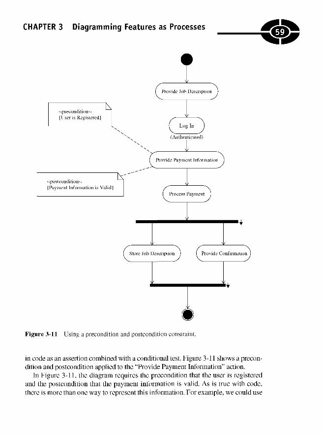
CHAPTER 3 Diagramming Features as Processes
Figure 3-11 Using a precondition and postcondition constraint.
in code as an assertion combined with a conditional test. Figure 3-11 shows a precon-dition and postcondition applied to the "Provide Payment Information" action.
In Figure 3-11, the diagram requires the precondition that the user is registeredand the postcondition that the payment information is valid. As is true with code,there is more than one way to represent this information. For example, we could use
59

UML Demystified
a guard condition before and after the "Provide Payment Information" action(Figure 3-12), or we could use a decision node (see "Decision and Merge Nodes")to branch to a register action before permitting payment information to be provided,and we could have an action to validate payment information after the paymentinformation is provided (Figure 3-13).
Figure 3-12 Using guards to express a precondition and a postcondition.
60
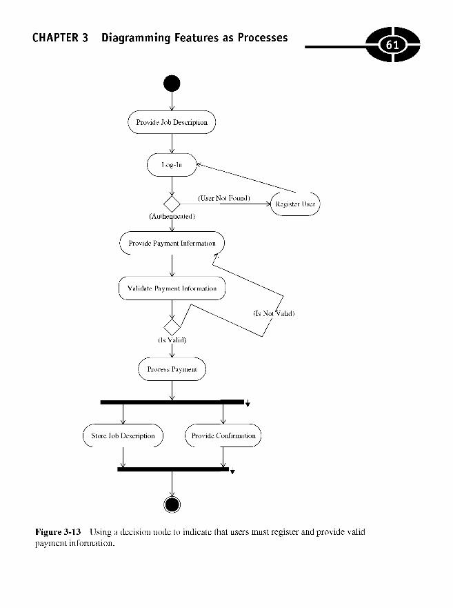
CHAPTER 3 Diagramming Features as Processes
Figure 3-13 Using a decision node to indicate that users must register and provide validpayment information.
61
UML Demystified
All three of these diagrams—Figures 3-11, 3-12, and 3-13—convey the sameinformation. The real difference is stylistic. If you want the diagram to appear lessbusy, try using the guard condition. If the constraint style—in Figure 3-11—seemsmore meaningful, then use that style. If you want to explore registration and addressvalidation, then use the decision node styles in Figure 3-13. In that figure, the deci-sion nodes are represented by the diamond-shaped symbols.
Modeling Subactivities
Sometimes it is easy to add too much detail to a single activity diagram, making thediagram busy and confusing. For example, if we expand "Register User" in Figure 3-13to include all the necessary actions for registering users, such as obtaining a uniqueuser name and password and validating and storing mailing address information,then the main focus of the activity—creating and paying for a job listing—may belost in the noise of all the additional actions and edges.
If in any instance we find the details of subactivities making a diagram too con-fusing, or we find that we want to reuse subactivities, then we can mark an actionas a subactivity with a fork inside the action. (Visio doesn't support the subsidiaryactivity symbol, so I drew one from scratch in Microsoft Paint and added it to the"Register User" action in Figure 3-13.)
TIP If you want to invent or find that an aspect of the UML isn't supported by yourspecific modeling tool, then consider using a stereotype or a note to document yourmeaning.
Decision and Merge NodesDecision and merge nodes were called decision diamonds in flowcharts. This diamond-shaped symbol is one of the elements that makes an activity diagram reminiscent ofa flowchart. Decision and merge nodes use the same symbol and convey condi-tional branching and merging.
When the diamond-shaped symbol is used as a decision node—after "Log-In" inFigure 3-13—it has one edge entering the node and multiple edges exiting the node.When used as a merge node, there are multiple entering edges and a single exitingedge. A decision node takes only one exit path, and a merge node doesn't exit untilall flows have arrived at the merge node.
The guard conditions on a decision node act like if..else logic and should bemutually exclusive, which necessarily implies that if one guard condition is met,then the other must fail. As depicted in Figure 3-13, you can stipulate both guardconditions literally or stipulate one guard condition and use an [Else] guard for thealternate condition.
62
CHAPTER 3 Diagramming Features as Processes
A merge node marks the end of conditional behavior started by a decision node.We don't need a merge node in Figure 3-13 because we rerouted the newly registereduser back to the "Log-In" action. However, if we wanted to be a little nicer, we mightsimply authenticate the new user automatically and proceed right to providing pay-ment information where he or she left off. This revision is shown using a merge nodein Figure 3-14. (Note that the guard conditions for the decision node following the"Log-In" action were modified to show the use of the [Else] guard style.)
Transition Forks and Joins
A fork exists to depict parallel behavior, and a join is used to converge parallel be-havior back into a single flow. Forked behavior does not specify whether or not thebehavior is interleaved or occurs simultaneously; the implication is simply that theforked actions are occurring during a shared, concurrent interval. Usually forkedbehavior is implemented as multithreaded behavior. (Figure 3-13 presents an ex-ample of a fork after the "Process Payment" action and a join immediately beforethe final node.)
When multiple flows enter an action, this is implicitly a join, and the meaning isthat the outgoing flow occurs only when all incoming flows have reached the action.Your diagrams will be clearer if you use forks and joins explicitly where you meanto show parallel behavior.
In Figure 3-13 we mean that we can store a job description and provide the userwith a confirmation simultaneously or concurrently but that both these things mustoccur before the activity is considered complete.
Partitioning Responsibility with Swimlanes
Sometimes you want to show who or what is responsible for part of an activity. Youcan do this with swimlanes. Modeling tools typically show swimlanes as a box witha name at the top, and you place whatever nodes and edges that belong to that thingin that swimlane. You can have as many swimlanes as it makes sense to have, butboxy swimlanes can make it hard to organize your activity diagram.
UML version 2.0 supports vertical, horizontal, and gridlike partitions, so theswimlane metaphor is no longer precise. The actual terminology is now activitypartition, but the word swimlane is still employed in general conversation and usedin modeling tools.
Using Swimlanes
If we want to show who or what is responsible for various actions in Figure 3-14,then we can add a swimlane (or partition) for what we believe the partitions to be.
63

UML Demystified
Figure 3-14 A merge node used to converge when a branch is taken after a new userregisters.
64
i

CHAPTER 3 Diagramming Features as Processes
In the example, we could say that posting a job is divided into two partitions, theuser and the system, and add a swimlane for each partition (Figure 3-15). If wedecided that payment processing represents a distinct partition, then we could adda third partition and move the process payment action into that partition (Figure 3-16).
Figure 3-15 Actions are divided between a user and the system.
65
i
i

UML Demystified
Figure 3-16 Further subdividing responsibilities by placing the "Validate PaymentInformation" and "Process Payment" actions in a separate partition called the "PaymentProcessor."
As is true with programming, you can divide your analysis and design into asmany partitions as you want. There are tradeoffs for adding partitions in models just
66

CHAPTER 3 Diagramming Features as Processes
as there are tradeoffs for adding partitions in code. Partitioning models may helpyou to organize, but all those partitions suggest partitioned software that will haveto be orchestrated and reassembled to accomplish the goals of the system.
Modeling Actions that Spans Partitions
Sometimes an action may belong to more than one partition at a time. For example,"Register User" really doesn't belong to the user or the system. We know fromearlier discussions that "Register User" is a subsidiary activity that may involve theuser providing personal information and the system validating address informationand storing the user information. However, the UML doesn't permit a node to spanmore than one partition in a single dimension. As a result, you will have to pick apartition for the node, and this also suggests what we know to be true about "Reg-ister User"—that it can be decomposed into its own activity.
Using Multidimensional Partitions
Modeling multidimensional activity partitions is a relatively new concept. Diagram-ming multidimensional activity partitions also doesn't seem to be wholly supportedby some popular and currently available modeling tools; however, you can simulatea multidimensional partition in Visio by adding two swimlanes (activity partitions)and rotating one of them. (The result is a diagram similar to Figure 3-17.) Now thatwe have the mechanics for creating a multidimensional partition, you might bewondering how it is used.
An action in an activity partition matrix belongs wholly to both partitions. Sup-pose, for example, that as we are gearing up to sell job listings on Motown-jobs.com, we decide to use PayPal to process payments. We can say that "Process Pay-ment" is part of both our "Payment Processor" and PayPal's payment-processingsystem, which is reflected in Figure 3-17.
Indicating Timed SignalsThus far we haven't talked about when things occur. There are three types of signalsthat facilitate talking about time in activity diagrams. These are the time signal, thesend signal, and the accept signal. A signal indicates that an outside event has fired,and that event initiates the activity.
The hourglass shape of the time signal is used to specify an interval of time. Forexample, we could use the time signal to indicate that the "Expire Listing" activitywill start after the listing has been available for 30 days (Figure 3-18). The receive
67
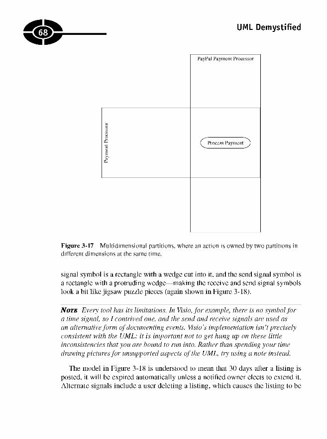
UML Demystified
Figure 3-17 Multidimensional partitions, where an action is owned by two partitions indifferent dimensions at the same time.
signal symbol is a rectangle with a wedge cut into it, and the send signal symbol isa rectangle with a protruding wedge—making the receive and send signal symbolslook a bit like jigsaw puzzle pieces (again shown in Figure 3-18).
NOTE Every tool has its limitations. In Visio, for example, there is no symbol fora time signal, so I contrived one, and the send and receive signals are used asan alternative form of documenting events. Visio's implementation isn't preciselyconsistent with the UML; it is important not to get hung up on these littleinconsistencies that you are bound to run into. Rather than spending your timedrawing pictures for unsupported aspects of the UML, try using a note instead.
The model in Figure 3-18 is understood to mean that 30 days after a listing isposted, it will be expired automatically unless a notified owner elects to extend it.Alternate signals include a user deleting a listing, which causes the listing to be
68
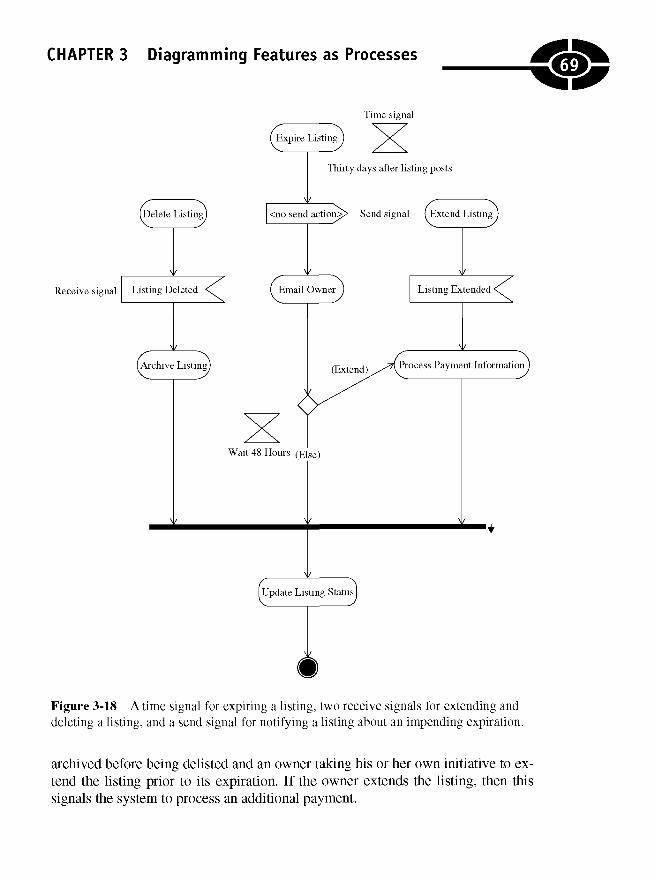
CHAPTER 3 Diagramming Features as Processes
Figure 3-18 A time signal for expiring a listing, two receive signals for extending anddeleting a listing, and a send signal for notifying a listing about an impending expiration.
archived before being delisted and an owner taking his or her own initiative to ex-tend the listing prior to its expiration. If the owner extends the listing, then thissignals the system to process an additional payment.
69

UML Demystified
Capturing Input Parameters
Activity diagrams can have input parameters, e.g., in Figure 3-18 in every instancethat we are talking about doing something with a listing. We could show a "List-ing" object as the input for each action in the figure. Grabbing just a small piece ofFigure 3-18, we can show the notation and symbol for indicating that the input tothat action is a "Listing" object (Figure 3-19).
While input objects can be useful for developers, this is another instance wherethey may add confusion to the discussion of the activity in a general, analyticalsense. At least during early phases of analysis, consider deferring specific referenceto implementation details such as classes.
Showing Exceptions in Activity Diagrams
The UML supports modeling exceptions. An exception is shown as a zigzaggingline (or "lightning bolt") with the name of the class of the exception adorning thezigzagging line. The exception handler can be modeled as an action node with the
Figure 3-19 The "Listing" object is shown as an input parameter to the "Extend Listing''action and its containing activity diagram.
70
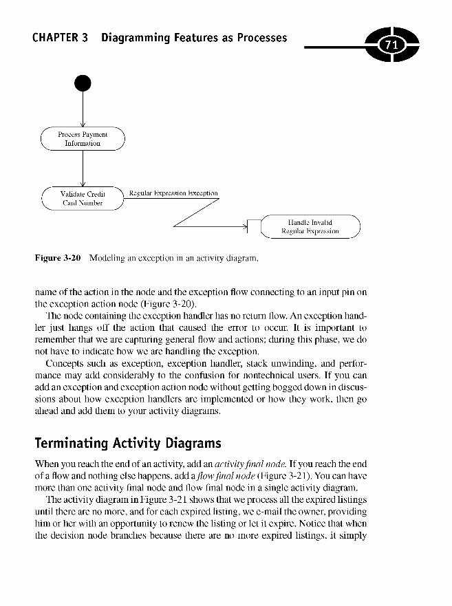
CHAPTER 3 Diagramming Features as Processes
Figure 3-20 Modeling an exception in an activity diagram.
name of the action in the node and the exception flow connecting to an input pin onthe exception action node (Figure 3-20).
The node containing the exception handler has no return flow. An exception hand-ler just hangs off the action that caused the error to occur. It is important toremember that we are capturing general flow and actions; during this phase, we donot have to indicate how we are handling the exception.
Concepts such as exception, exception handler, stack unwinding, and perfor-mance may add considerably to the confusion for nontechnical users. If you canadd an exception and exception action node without getting bogged down in discus-sions about how exception handlers are implemented or how they work, then goahead and add them to your activity diagrams.
Terminating Activity Diagrams
When you reach the end of an activity, add an activity final node. If you reach the endof a flow and nothing else happens, add a flow final node (Figure 3-21). You can havemore than one activity final node and flow final node in a single activity diagram.
The activity diagram in Figure 3-21 shows that we process all the expired listingsuntil there are no more, and for each expired listing, we e-mail the owner, providinghim or her with an opportunity to renew the listing or let it expire. Notice that whenthe decision node branches because there are no more expired listings, it simply
71
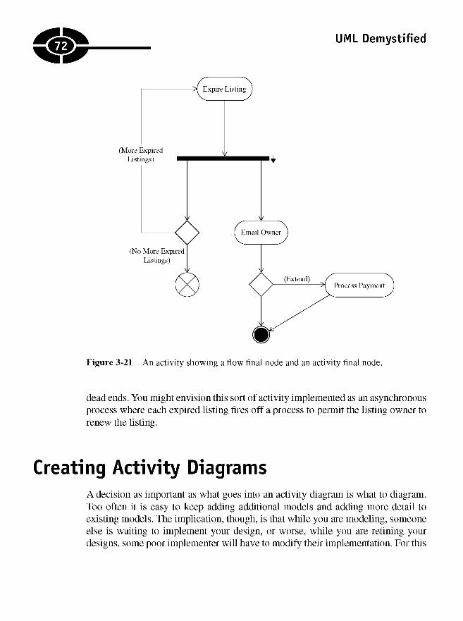
UML Demystified
Figure 3-21 An activity showing a flow final node and an activity final node.
dead ends. You might envision this sort of activity implemented as an asynchronousprocess where each expired listing fires off a process to permit the listing owner torenew the listing.
Creating Activity DiagramsA decision as important as what goes into an activity diagram is what to diagram.Too often it is easy to keep adding additional models and adding more detail toexisting models. The implication, though, is that while you are modeling, someoneelse is waiting to implement your design, or worse, while you are refining yourdesigns, some poor implementer will have to modify their implementation. For this
72

CHAPTER 3 Diagramming Features as Processes
reason, it is important to make your activity diagrams relatively simple; limit theactivity diagrams you create to important, critical, or challenging aspects of yourproblem; and avoid trying to make them perfect. A good model that is easy tounderstand and completed in a timely matter is more valuable than a perfect modellater—if there is such a thing as a perfect model.
Examples of the activity diagrams I would create for use cases from Chapter 2might be an activity for "Manage Job Listing," "Expire Listing," and "MaintainBilling Information." Specifically, I am interested in understanding the critical as-pects of the system, especially those for services that are billable items. Commonthings such as searching or logging are understood well enough that it is unlikelythat I would create an activity diagram for them.
Picking what to model and what not to model is a lot like adding salt duringcooking: You can always add a little more, but it is hard to remove salt if you haveadded too much. The same is true with modeling: You cannot recoup time spentmodeling obvious activities, but you always can add more activity diagrams later ifyou need to.
Reengineering ProcessProbably the most beneficial use of activity diagrams is to help nondomainpersonnel—usually the technologists who will implement a solution—understanda domain. Implicit in the preceding statement is that while domain experts andtechnologists are attempting to reach a common understanding, there is an opportu-nity to reengineer the process. Let's take a moment to review what is meant byprocess reengineering.
Frequently, people do there jobs every day without ever identifying a formalprocess. The process knowledge is known only to the practitioners. Often thesesame organizations are shocked to discover how much overhead and waste existwithin their organization. Process reengineering is a kind of pseudoscience thatentails first documenting an organization's processes and then looking for ways tooptimize those processes.
I am not an expert in process reengineering, but there are historical exampleswhere well-known companies have spent a considerable amount of money and en-ergy to refine their business processes, and the results have led to broad, sweepingchanges in industry. An interesting example can be found in Behind the GoldenArches, which details the evolutionary path that led McDonald's to use centralizeddistribution centers for its franchisees.
73

UML Demystified
NOTE Ironically enough, software development itself is an example of a domainwhere the practitioners have defined the process in an ad hoc way. Many softwarecompanies are now beginning to realize that they are long overdue for an introspectiveexamination of the processes they follow to build software. Has anyone in yourorganization every used an activity diagram (or flowchart) to document how yourorganization builds software?
Software development is a business of automating solutions to problems. Ina general sense it is a useful idea to document critical domain processes and exploresome possible optimizations before writing code. If the process is simplified, thenthe ensuing implementation may be markedly simplified too.
Reengineering a Subactivity
Here is an example involving a subactivity called "Interior Cabin Check" that hasto do with the preflight inspection of a small airplane. The idea behind the interiorcabin check is that we are looking for required or important things in the interior ofthe airplane and performing steps to help with some exterior checks. There is a verygood likelihood that if we miss something, then we could be taking off with unsafeconditions or not have critical resources during an emergency. (If it bothers you thatthis doesn't sound like a software problem, then just imagine that we are document-ing this problem to write testing or simulation software.)
One of the planes I fly is a Cessna 172 Skyhawk. The interior cabin check(depicted in Figure 3-22) consists of
• Making sure the ignition switch is off
• Turning the master switch on so that we have power
• Lowering the flaps
• Checking for the registration, airworthiness certificate, weight and balanceinformation, and operating handbook, which includes emergency procedures
• Checking the fuel level indicators and fuel selector
• Turning the master switch off
As shown in the activity diagram in Figure 3-22, the steps are carried out con-secutively. (This is the way that I performed the inspection the first couple of timesI performed it.) An experienced pilot (a domain expert) will tell you that it takes
74
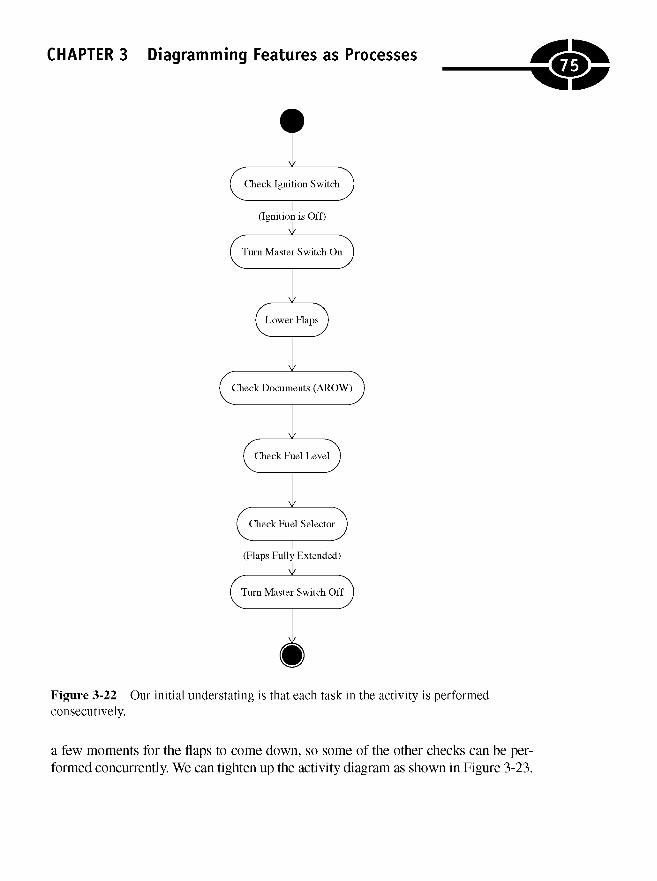
CHAPTER 3 Diagramming Features as Processes
Figure 3-22 Our initial understating is that each task in the activity is performedconsecutively.
a few moments for the flaps to come down, so some of the other checks can be per-formed concurrently. We can tighten up the activity diagram as shown in Figure 3-23.
75
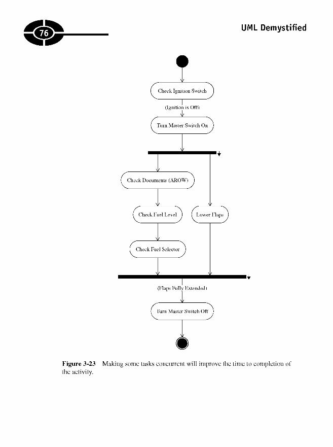
UML Demystified
Figure 3-23 Making some tasks concurrent will improve the time to completion ofthe activity.
76

Knowing When to QuitApplying rules consistently will help you to work efficiently during the modelingphase of development. With this in mind, recall that I said that an important idea isto capture the most critical use cases and tackle those first. The same is true of activ-ity diagrams. Identify the use cases that are most critical, and create activity diagramsfor those use cases that require some exploration. For instance, authenticating a userin Motown-jobs.com is necessary, but this is a well-understood problem. I wouldn'tspend a lot of time creating an activity diagram for this, and I wouldn't work on thatactivity diagram before I worked on those related to my primary use case, "ManageJob Listing."
If you are not sure how many activity diagrams to create, then try creating anactivity diagram for each of the primary functions of your most important use cases.Try to get as much about the activity modeled as quickly and as accurately as youcan. Immediately check back with your domain experts, and explore the activitiesto see if you have captured the most salient points.
Finally, don't permit yourself to get bogged down here. If you can't reach a consen-sus on the completeness of a particular activity, then set it aside and agree to come backto it. There may be other elements of the problem that will increase your understandingor your users' understanding of the problem in general and resolve the problem you setaside. The key is not to get stuck on any particular problem too early.
Quiz1. Synonyms for a transition are
a. connector and flow.
b. edge and flow.
c. edge and connector.
d. action and event.
2. In general, activity diagrams consist of
a. nodes and edges.
b. actions and transitions.
c. actions, decisions, and flows.
d. symbols and lines.
77CHAPTER 3 Diagramming Features as Processes

UML Demystified
3. An exception can be shown in an activity diagram with a lightning bolt-shaped edge.
a. True
b. False
4. A decision node and merge node use
a. different symbols.
b. identical symbols.
c. either identical or differing symbols depending on context.
5. Multiple flows entering an action node constitute
a. an implicit merge.
b. an implicit join.
6. Every flow waits at a merge and join until all flows have arrived.
a. True
b. False
7. The swimlane metaphor is no longer used
a. because swimlanes are no longer part of the UML.
b. because partitions can be multidimensional and don't look likeswimlanes.
c. The swimlane metaphor is still in use.
d. Both b and c.
8. Actions can exist in two activity partitions in different dimension at thesame time.
a. True
b. False
9. A decision and merge node is represented by
a. an oval.
b. a circle.
c. a rectangle.
d. a diamond.
78

CHAPTER 3 Diagramming Features as Processes
10. Activity diagrams differ from flowcharts because activity diagrams support
a. swimlanes.
b. parallel behavior.
c. decision nodes.
d. actions.
Answers1. b
2. a
3. a
4. b
5. b
6. a
7. d
8. a
9. d
10. b
JTJ1

This page intentionally left blank
CHAPTER
DiscoveringBehaviors with
InteractionDiagrams
Demystify means to "expose, set straight, or throw light on," and each chapter doesthis implicitly or explicitly. In this chapter I'd like to start off by setting you straightright away. There are all kinds of Unified Modeling Language (UML) diagrams.Some are redundant, and you definitely do not have to create every kind of diagramto have a good design. There is more than one kind of interaction diagram, and therule of avoiding redundancy is apropos to this chapter.
4
81
Copyright © 2005 by The McGraw-Hill Companies. Click here for terms of use.
UML Demystified
The two common interaction diagrams are the sequence and the collaboration(or communication) diagrams. These diagrams tell you exactly the same thing. Se-quences have an explicit time ordering and are linear, and collaborations havea "labeled" time ordering and are geometric. You only need one or the other, butdefinitely not both.
I like sequence diagrams. Sequence diagrams are more common, very easy tocreate, and are naturally organized, and we don't need to indicate the time orderingby annotating the messages. Consequently, in this chapter I will emphasize the se-quence diagram, but I will talk briefly (and demonstrate) collaboration diagrams sothat you are familiar with them. (If you decide ultimately you like the geometricorganization of collaboration diagrams, then use those. Remember, though, thatyou don't need both sequences and collaborations, and many UML tools will read-ily convert sequences to collaborations and vice versa automatically.)
In this chapter I will show you how to
• Identify the elements of sequence diagrams
• Create sequence and collaboration diagrams
• Understand the time ordering of interaction diagrams
• Use interaction diagrams to discover classes and methods
• Model success and failure scenarios using interaction frames introducedin UML version 2.0
• Use sequences to explore the behavior of many objects across a use case
Elements of Sequence DiagramsEvery diagram uses only a subset of the tokens and grammar that make up theUML. Learning about those tokens and the specific grammar is an essential evil. Itis important to remember that you don't need to remember every word in a lan-guage to communicate effectively—for example, I can't remember what solecismmeans precisely, as in "for it is the solecism of a prince to think to control the endyet not endure the mean"—but it is important to master a language to employ itcreatively.
NOTE It is important to remember that the UML is an evolving language. Aswith spoken languages, effective communication can occur with a very basicunderstanding of the language. The key is to remember to leave the languagelawyering to others. (In this case, leave the language lawyering to the ObjectManagement Group.)
82

CHAPTER 4 Discovering Behaviors with Interaction Diagrams
Let's take a couple of minutes to explore the useful tokens and grammar of se-quence diagrams. We will begin with the two basic and essential elements of sequencediagrams—lifelines and messages. (It is worthwhile to note that a passable dialoguecan occur with just these two elements of sequence diagrams.)
Using Object LifelinesA lifeline is a rectangle with a vertical line descending from the rectangle. The life-line represents an instance of a class, and the vertically descending line is a convenientplace to attach incoming and outgoing messages. Adding multiple lifelines to a sin-gle diagram and attaching these with time-ordered messages permits you to show allthe classes and messages necessary to complete a scenario described by a use case.By eliminating ambiguous gaps or avoiding the repetition of classes and messages,you can get a whole solution, one scenario at a time.
An object lifeline takes form as an object that plays a part of a role in a use case. I'lltalk more about lifelines as we progress; for now, just look at the symbol in Figure 4-1.
Object lifelines can represent actors or objects. Both actors and objects may ormay not be actualized as code. This may sound confusing, but it is not. Suppose, forexample, that we are building an airline ticketing reservation system. An actor mightbe a person working the counter in the terminal or a kiosk (used for e-tickets).The person is an important participant in the ticketing sequence but will not berepresented by code. A kiosk is also an important participant, and it will be repre-sented by code to some extent. Thus we can refer to an actor called a "TicketingAuthority" and mean both the person and the kiosk.
In some modeling tools, the stick-figure actor is used with an attached lifeline, andin others, a box with a stick figure or «actor» stereotype is used. More important
Figure 4-1 An object lifeline represents an instance of a class and a line convenientlyplaced to permit connecting objects by messages.
83

UML Demystified
than the precise notation is to remember that an actor may or may not be realized incode and that a lifeline can be an actor.
A lifeline also can represent an actualized class. What is important to know isthat a lifeline is generally a noun that may or may not be codified as a class but isdefinitely something that can interact with your system and that a lifeline is also justa rectangle with a vertical line descending from it.
Activating a LifelineObjects have a lifetime. For example, in a deterministic language such as C++, anobject lives until the destructor is called. In a nondeterministic language such as C#(pronounced "C sharp"), an object lives until it is garbage collected. This means thatthe programmer doesn't really know when the object goes away. However, modelersare not entirely constrained by the implementation language.
From our perspective, we only care when we begin using an object and when weare done using an object unless the object represents a finite resource. In both cases,the activation line represents the span of an object's lifetime for practical purposes.It is also important to know that an object can be represented as being created anddestroyed using a single lifeline.
The activation symbol is a vertical rectangle replacing the lifeline for the dura-tion of that instance's existence (Figure 4-2), keeping in mind that an object can becreated and destroyed multiple times and that one lifeline is used to represent all
Figure 4-2 A lifeline with an annotated activation symbol.
84

CHAPTER 4 Discovering Behaviors with Interaction Diagrams
instances of that class in a sequence. (I will talk about deterministic destruction ina minute.) If we want to express nested or recursive messages, then we can stackactivation symbols horizontally.
Sending MessagesMessages are directed lines connecting lifelines. The line begins at one lifeline, andthe arrow points toward a lifeline containing the message invoked. The message canbegin and end on the same lifeline; this is a nested call. A filled-in triangle repre-sents a synchronous message. A stick triangle represents an asynchronous message,and a dashed line is used for return messages. Included as possible messages arefound messages and lost messages. A found message is a message with a knownreceiver, but the sender is not known, and a lost message has a known sender but nospecified receiver. Figure 4-3 shows each type of message clearly labeled.
Figure 4-3 Synchronous and asynchronous method call symbols.
85
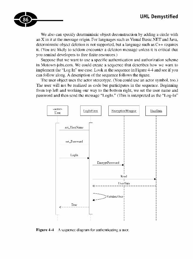
UML Demystified
We also can specify deterministic object deconstruction by adding a circle withan X in it at the message origin. For languages such as Visual Basic.NET and Java,deterministic object deletion is not supported, but a language such as C++ requiresit. (You are likely to seldom encounter a deletion message unless it is critical thatyou remind developers to free finite resources.)
Suppose that we want to use a specific authentication and authorization schemein Motown-jobs.com. We could create a sequence that describes how we want toimplement the "Log In" use case. Look at the sequence in Figure 4-4 and see if youcan follow along. A description of the sequence follows the figure.
The user object uses the actor stereotype. (You could use an actor symbol, too.)The user will not be realized as code but participates in the sequence. Beginningfrom top left and working our way to the bottom right, we set the user name andpassword and then send the message "Login." (This is interpreted as the "Log-In"
Figure 4-4 A sequence diagram for authenticating a user.
86
CHAPTER 4 Discovering Behaviors with Interaction Diagrams
form having a method named "Login.") Next, the user-supplied password is en-crypted and compared with the encrypted password stored as part of the UserData. IfValidateUser succeeds, then we return a Boolean message true.
The sequence diagram is good at showing us how objects are orchestrated andused across a use case, but they aren't good at showing us how this behavior isimplemented. For example, we could use Secure Hash Algorithm 1 (SHA1) en-cryption with a salt and store the user data with an encrypted password, but thesequence doesn't make this clear. (For a resolution as to how to implement a se-quence, refer to the section entitled, "Understanding What Sequences Tell Us.")
Adding Constraints and Notes
You can add notes and constraints to help disambiguate the meaning of particularaspects of your sequence diagrams. The UML describes how these elements are add-ed, but in practice, they vary some depending on the tool you use. For example, wecould add a note to the diagram in Figure 4-4 that indicates that we are using SHA1and a salt value and storing the password in an encrypted form only (Figure 4-5).
Constraints can be added as plain text, pseudocode, actual code, or ObjectConstraint Language (OCL). Actual code or OCL constraints can be used to helpcode-generating UML tools generate lines of code. In some heavyweight modelingprocesses, the ability to generate code may be a requirement, but to date, it seemsharder to create UML models that generate granular code than it is to write the codeitself. You will have to decide for yourself if you need moderately detailed or verydetailed models.
TIP Models that generate complete applications are unrealistic and impractical.Avoid falling into the trap of trying to create perfect models with enough detail tospit out an application.
Using Interaction Frames
Interaction frames (or combined fragments) are new in UML version 2.0. Interac-tion frames are rectangular regions used to organize interaction diagrams (sequenceand timing diagrams). Interaction frames can surround an entire interaction dia-gram or just part of a diagram. Each interaction frame is tagged with a specificword (or an abbreviated form of that word), and each kind of interaction frameconveys some specific information. Table 4-1 defines the current interaction frametypes.
87

UML Demystified
Figure 4-5 Using notes to add detail to your sequence diagrams.
Table 4-1 The Types of Interaction Frames
faa
Alt Alternatives fragments (i.e., conditional logic); only guard conditions evaluating totrue will execute.
Loop The guard indicates how many times this part will execute.
Neg An invalid interaction.
Opt Equivalent to an alt with one condition (i.e., an if condition with no else statement).
Par Fragments are run in parallel—think multithreading.
Ref Reference to an interaction defined on another diagram.
Region Critical region; think not reentrant or only one thread at a time.
Sd Used to surround an entire sequence diagram, if desired.
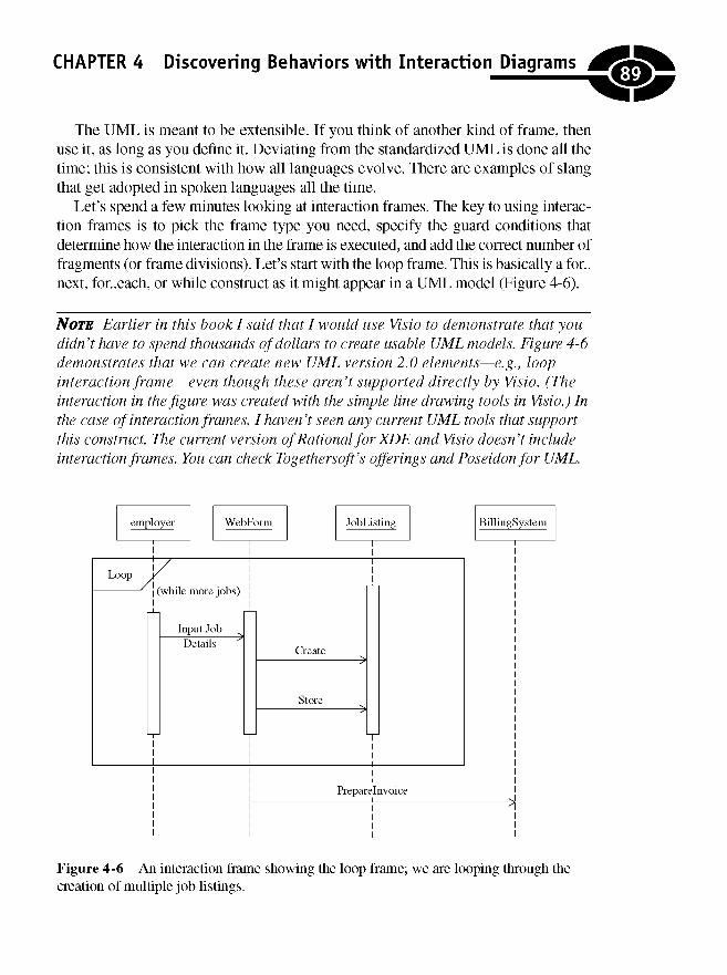
CHAPTER 4 Discovering Behaviors with Interaction Diagrams
The UML is meant to be extensible. If you think of another kind of frame, thenuse it, as long as you define it. Deviating from the standardized UML is done all thetime; this is consistent with how all languages evolve. There are examples of slangthat get adopted in spoken languages all the time.
Let's spend a few minutes looking at interaction frames. The key to using interac-tion frames is to pick the frame type you need, specify the guard conditions thatdetermine how the interaction in the frame is executed, and add the correct number offragments (or frame divisions). Let's start with the loop frame. This is basically a for.,next, for..each, or while construct as it might appear in a UML model (Figure 4-6).
NOTE Earlier in this book I said that I would use Visio to demonstrate that youdidn't have to spend thousands of dollars to create usable UML models. Figure 4-6demonstrates that we can create new UML version 2.0 elements—e.g., loopinteraction frame—even though these aren't supported directly by Visio. (Theinteraction in the figure was created with the simple line drawing tools in Visio.) Inthe case of interaction frames, I haven't seen any current UML tools that supportthis construct. The current version of Rational for XDE and Visio doesn't includeinteraction frames. You can check Togethersoft's offerings and Poseidon for UML.
Figure 4-6 An interaction frame showing the loop frame; we are looping through thecreation of multiple job listings.
.89^

UML Demystified
We read the sequence diagram the same as before, except that all the messagesin the loop frame are part of the repeating behavior that this sequence describes.(An older-style notation was to use an asterisk as a guard condition. The same modelusing the multiplicity symbol (an asterisk) is shown in Figure 4-7.)
The key to successful modeling is to remember that it happens in a world withreal constraints—budget for tools, available time, the tool's compatibility, the cur-rent definition of the UML, and so on. Don't get hung up language lawyering. Ifyour tool doesn't support a particular construct, fudge. In practice, I would not takethe time to manually draw an interaction frame if my tool didn't support it; I'd usethe asterisk guard condition.
Figure 4-8 shows another common interaction frame, the alternative frame. Sup-pose that we offer perquisites for customers who frequently post a certain numberof jobs. We may want to pass these customers to a different billing system, perhapsoffering a special volume discount.
Figure 4-7 The guard condition—[*]—by the name of the "Input Job Details" messageindicates multiplicity or repetition, employing an older style devised to indicate a loop.
Eil
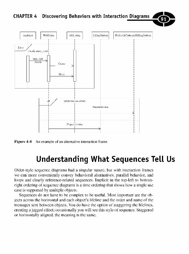
CHAPTER 4 Discovering Behaviors with Interaction Diagrams
Figure 4-8 An example of an alternative interaction frame.
Understanding What Sequences Tell UsOlder-style sequence diagrams had a singular nature, but with interaction frameswe can more conveniently convey behavioral alternatives, parallel behavior, andloops and clearly reference-related sequences. Implicit in the top-left to bottom-right ordering of sequence diagrams is a time ordering that shows how a single usecase is supported by multiple objects.
Sequences do not have to be complex to be useful. Most important are the ob-jects across the horizontal and each object's lifeline and the order and name of themessages sent between objects. You do have the option of staggering the lifelines,creating a jagged effect; occasionally you will see this style of sequence. Staggeredor horizontally aligned, the meaning is the same.
91
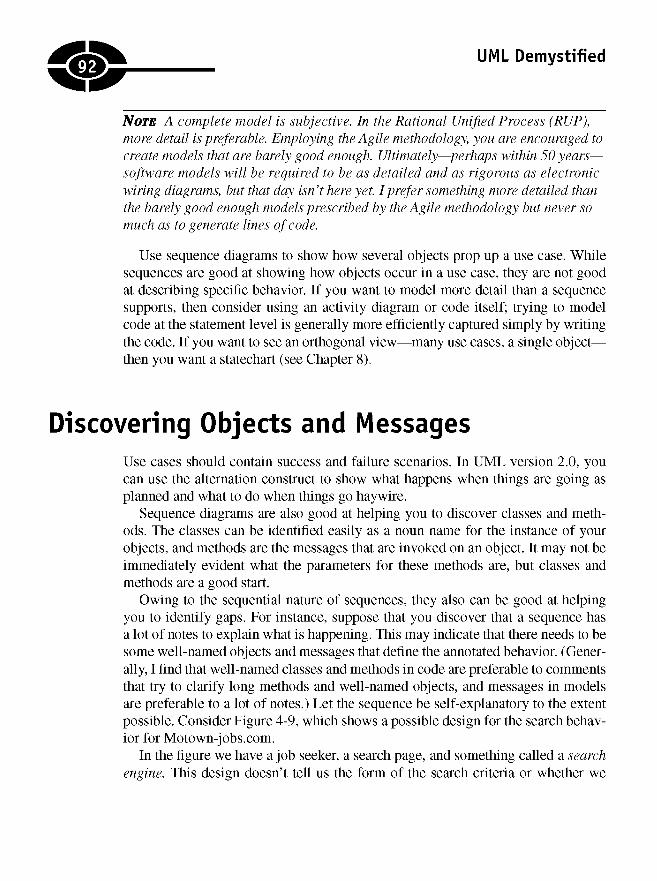
UML Demystified
NOTE A complete model is subjective. In the Rational Unified Process (RUP),more detail is preferable. Employing the Agile methodology, you are encouraged tocreate models that are barely good enough. Ultimately—perhaps within 50 years—software models will be required to be as detailed and as rigorous as electronicwiring diagrams, but that day isn't here yet. I prefer something more detailed thanthe barely good enough models prescribed by the Agile methodology but never somuch as to generate lines of code.
Use sequence diagrams to show how several objects prop up a use case. Whilesequences are good at showing how objects occur in a use case, they are not goodat describing specific behavior. If you want to model more detail than a sequencesupports, then consider using an activity diagram or code itself; trying to modelcode at the statement level is generally more efficiently captured simply by writingthe code. If you want to see an orthogonal view—many use cases, a single object—then you want a statechart (see Chapter 8).
Discovering Objects and MessagesUse cases should contain success and failure scenarios. In UML version 2.0, youcan use the alternation construct to show what happens when things are going asplanned and what to do when things go haywire.
Sequence diagrams are also good at helping you to discover classes and meth-ods. The classes can be identified easily as a noun name for the instance of yourobjects, and methods are the messages that are invoked on an object. It may not beimmediately evident what the parameters for these methods are, but classes andmethods are a good start.
Owing to the sequential nature of sequences, they also can be good at helpingyou to identify gaps. For instance, suppose that you discover that a sequence hasa lot of notes to explain what is happening. This may indicate that there needs to besome well-named objects and messages that define the annotated behavior. (Gener-ally, I find that well-named classes and methods in code are preferable to commentsthat try to clarify long methods and well-named objects, and messages in modelsare preferable to a lot of notes.) Let the sequence be self-explanatory to the extentpossible. Consider Figure 4-9, which shows a possible design for the search behav-ior for Motown-jobs.com.
In the figure we have a job seeker, a search page, and something called a searchengine. This design doesn't tell us the form of the search criteria or whether we
92:
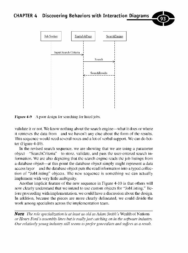
CHAPTER 4 Discovering Behaviors with Interaction Diagrams
Figure 4-9 A poor design for searching for listed jobs.
validate it or not. We know nothing about the search engine—what it does or whereit retrieves the data from—and we haven't any clue about the form of the results.This sequence would need several notes and a lot of verbal support. We can do bet-ter (Figure 4-10).
In the revised search sequence, we are showing that we are using a parameterobject—"SearchCriteria"—to store, validate, and pass the user-entered search in-formation. We are also depicting that the search engine reads the job listings froma database object—at this point the database object simply might represent a dataaccess layer—and the database object puts the read information into a typed collec-tion of "JobListing" objects. The new sequence is something we can actuallyimplement with very little ambiguity.
Another implicit feature of the new sequence in Figure 4-10 is that others willnow clearly understand that we intend to use custom objects for "JobListing." Be-fore proceeding with implementation, we could have a discussion about the design.In addition, because the pieces are more clearly delineated, we could divide thework among specialists across the implementation team.
NOTE The role specialization is at least as old as Adam Smith's Wealth of Nationsor Henry Ford's assembly lines but is really just catching on in the software industry.Our relatively young industry still seems to prefer generalists and suffers as a result.
93
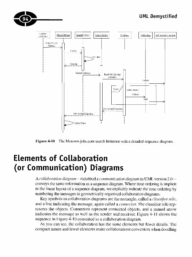
UML Demystified
Figure 4-10 The Motown-jobs.com search behavior with a detailed sequence diagram.
Elements of Collaboration(or Communication) Diagrams
A collaboration diagram—redubbed a communication diagram in UML version 2.0—conveys the same information as a sequence diagram. Where time ordering is implicitin the linear layout of a sequence diagram, we explicitly indicate the time ordering bynumbering the messages in geometrically organized collaboration diagrams.
Key symbols in collaboration diagrams are the rectangle, called a classifier role,and a line indicating the message, again called a connector. The classifier role rep-resents the objects. Connectors represent connected objects, and a named arrowindicates the message as well as the sender and receiver. Figure 4-11 shows thesequence in Figure 4-10 converted to a collaboration diagram.
As you can see, the collaboration has the same elements but fewer details. Thecompact nature and fewer elements make collaborations convenient when doodling
>j
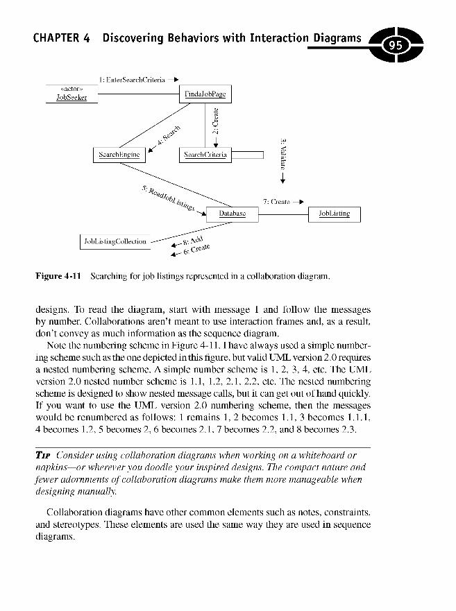
CHAPTER 4 Discovering Behaviors with Interaction Diagrams
designs. To read the diagram, start with message 1 and follow the messagesby number. Collaborations aren't meant to use interaction frames and, as a result,don't convey as much information as the sequence diagram.
Note the numbering scheme in Figure 4-11.1 have always used a simple number-ing scheme such as the one depicted in this figure, but valid UML version 2.0 requiresa nested numbering scheme. A simple number scheme is 1,2, 3, 4, etc. The UMLversion 2.0 nested number scheme is 1.1, 1.2, 2.1, 2.2, etc. The nested numberingscheme is designed to show nested message calls, but it can get out of hand quickly.If you want to use the UML version 2.0 numbering scheme, then the messageswould be renumbered as follows: 1 remains 1, 2 becomes 1.1,3 becomes 1.1.1,4 becomes 1.2, 5 becomes 2, 6 becomes 2.1, 7 becomes 2.2, and 8 becomes 2.3.
TIP Consider using collaboration diagrams when working on a whiteboard ornapkins—or wherever you doodle your inspired designs. The compact nature andfewer adornments of collaboration diagrams make them more manageable whendesigning manually.
Collaboration diagrams have other common elements such as notes, constraints,and stereotypes. These elements are used the same way they are used in sequenceHi arrramc
Figure 4-11 Searching for job listings represented in a collaboration diagram.
95

UML Demystified
Equating Design to CodeInteraction diagrams provide you with enough information to begin coding. Theobjects are instances of classes, so you need to define a class for each object. Mes-sages generally equate to methods, and the method is placed in the class of thereceiver (not the caller).
I have found generally that with sequences I have most of the information I needto start writing code. How the code is implemented is based on a couple of factors:(1) your experience and (2) the implementation language. For example, "JobList-ing" and "JobListingCollection" represent a class and a collection containingobjects of that class. If we were to implement this in C#, then "JobListingCollec-tion" could inherit from "System.Collections.CollectionBase," and that decisiondrives its implementation (see the listing).
public class JobListing
{}
public class JobListingCollection: System.Collections.CollectionBase
{public JobListing this[int index]
{get{return (JobListing)List[index];}set{List[index] = value;}
}
public int Add(JobListing value){
return List.Add(value);
Notice that in this listing I inherit from a specific base collection and define aproperty called this and the add method shown in the sequence. It is important tonote that the designed sequence didn't indicate the this property or the parent class;sequence diagrams won't. In this instance the implementation language—Micro-soft C# and the .NET framework—drove this part of the decision. Also notice thatthe job listing doesn't tell us anything; its an empty class. Well, the "JobListing" inthe sequence didn't tell us anything either. Sequence diagrams aren't good at spec-ifying code details. We did, however, stub out interfaces. At this point it depends onthe experience of your developers how much code they can write. Less experienceddevelopers will need more details, and more experienced developers will need fewerdetails. I tend to model detail that is sufficient for my audience—the developersdoing the implementation.
96
}}
CHAPTER 4 Discovering Behaviors with Interaction Diagrams
To begin to specify more details, such as properties, supporting methods, andinheritance relationships, we can use class diagrams. Chapter 5 goes into greaterdepth about class diagrams.
Keep in mind that there is a lot of implicit knowledge at this stage. First, youshould know that your design is likely to change. Second, things such as typed col-lections are based on patterns, and as is demonstrated in the code listing,implementation is driven by the language and framework. Third, there are manycommon and popular design patterns (see Erich Gamma et al., Design Patterns.Reading, MA: Addison Wesley, 1995), and it isn't always necessary to do muchmore than state that a pattern is used; you aren't absolutely required to create mod-els for well-known public patterns. And last but not least, there is a subject knownas refactoring. Refactoring is a methodical means of simplifying code. Refactoringstems from a doctoral thesis by William Opdike and a well-publicized book byMartin Fowler (see Refactoring: Improving the Design of Existing Code. Reading,MA: Addison Wesley, 1999). When refactoring is employed, it may mean inpractice that a design decision can be improved on during implementation. If therefactoring is better than the design, then go ahead and modify the code and simplyupdate the model to reflect the change.
NOTE We demonstrated a refactoring in design in Figures 4-9 and 4-10 whenwe introduced the "SearchCriteria" object. This refactoring is named "IntroduceParameter Object," which simply replaces a long list of parameters with a singleinstance of a parameter class that contains those values. We also snuck in a designpattern, "Iterator." The strongly typed collection implemented as a response toFigure 4-10's typed collection of "JobListing" objects inherits from .NET'sCollectionBase, which, in turn, implements an lEnumerable pattern (animplementation of the iterator pattern). Good designs and implementations arebased on patterns and refactorings. Good design models are based on a simple,accurate, and direct use of the UML and incorporate design patterns and refactorings.
Quiz1. A sequence diagram is an example of
a. a collaboration diagram.
b. an interaction diagram.
c. a class diagram.
d. a use case diagram.
97
UML Demystified
2. Sequence diagrams depict all the objects that support a single use case.
a. True
b. False
3. Sequence diagrams are good at showing how to implement lines of code.
a. True
b. False
4. A collaboration diagram and a communication diagram differ
a. because collaboration diagrams show that objects interact andcommunication diagrams show how objects communicate.
b. not at all; collaboration diagrams simply were renamed in UMLversion 2.0.
c. because collaboration diagrams are geometric and communicationdiagrams are linear.
d. Both a and c
5. Sequence diagrams can model asynchronous and multithreaded behavior.
a. True
b. False
6. Interaction frames use a guard condition to control when and which fragmentof the frame to execute.
a. True
b. False
7. The alt—called an interaction operator—interaction frame
a. is used to show an invalid fragment.
b. models optional behavior.
c. shows conditional logic.
d. models parallel behavior.
8. A good design must include both sequence and collaboration diagrams.
a. True
b. False
9. Activation symbols are used to show
a. the lifetime of an object in a sequence diagram.
b. the lifetime of an object in a communication diagram.
98

CHAPTER 4 Discovering Behaviors with Interaction Diagrams
c. when an object is created.
d. None of the above
10. Valid UML version 2.0 employs
a. a nested numbering scheme to show time ordering in a sequencediagram.
b. a nested number scheme to show time ordering in a communicationdiagram.
c. a simple numbering scheme to show time ordering in a sequencediagram.
d. a simple numbering scheme to show time ordering in a collaborationdiagram.
Answers1. b
2. a
3. b
4. b
5. a
6. a
7. c
8. b
9. a
10. b
99

This page intentionally left blank
CHAPTER
What Are theThings ThatDescribe My
Problem?
This chapter introduces class diagrams. Class diagrams are the most common andthe most important view of the design that you will create. Class diagrams arecalled static diagrams because they don't depict action. What class diagrams do isshow you things and their relationships. Class diagrams are designed to show all thepieces of your solution—which pieces are related to or used as parts of newwholes—and should convey a sense of the system to be built at rest.
5
noc
Copyright © 2005 by The McGraw-Hill Companies. Click here for terms of use.
UML Demystified
To communicate at a technically precise level in Unified Modeling Language(UML)-speak, it helps to learn such words as association, composition, aggregation,generalization, and realization, but to communicate sufficiently and effectively, allyou must know are simple words to describe whole and part relationships, i.e., parentand child relationships, and be able to describe how many of a thing of one sort arerelated to how many things of another sort. I will introduce the technical terms, butdon't get stuck trying to memorize them. With practice, eventually you will incorpo-rate UML-speak into your daily language.
A common myth is that if you find all the nouns and all the verbs that describeyour problem, then you have discovered all the classes and methods you will need.This is incorrect. The truth is that the nouns and verbs that describe your problemsufficiently for a user are the easiest classes to find and can help you to completea useful analysis of the problem, but you will end up designing and using manymore classes that are necessary to fill in the blanks.
This chapter will show you how to create class diagrams and begin helping youto figure out how to find most or all of the classes you will need to design a solution.An important concept here is that very few designs require that all details be discov-ered before programming ensues. (A few agencies and companies, such as NASAand General Dynamics, may have rigid requirements that stipulate the complete-ness of a design, but in most instances this leads to very long production times andexcessive expense.)
In this chapter I will show you how to use the elements of class diagrams, createclass diagrams, and capture some advance ideas, and I will show you some ways todiscover some less obvious classes and behaviors. You will learn how to
• Identify and use class diagram elements
• Create simple but useful class diagrams
• Model some advanced expressions
• Figure out how to discover less obvious supporting classes and behaviors
Elements of Basic Class DiagramsFoolishly, in high school I didn't like literature class and was stupefied by grammarclasses. Fortunately, by college, I began to see the error of my thinking. While I amnot an expert on English grammar, understanding such things as prepositions, prep-ositional phrases, conjunctions, objects, subjects, verbs, verb tense, adjectives,adverbs, articles, active voice and passive voice, and plural and singular possessivewords helps a lot when writing these passages. The reason I tell you this is that,
102
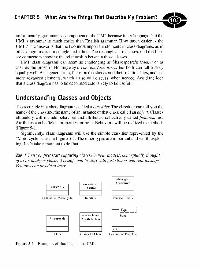
CHAPTER 5 What Are the Things That Describe My Problem?
unfortunately, grammar is a component of the UML because it is a language, but theUML's grammar is much easier than English grammar. How much easier is theUML? The answer is that the two most important elements in class diagrams, as inother diagrams, is a rectangle and a line. The rectangles are classes, and the linesare connectors showing the relationship between those classes.
UML class diagrams can seem as challenging as Shakespeare's Hamlet or aseasy as the prose in Hemingway's The Sun Also Rises, but both can tell a storyequally well. As a general rule, focus on the classes and their relationships, and usemore advanced elements, which I also will discuss, when needed. Avoid the ideathat a class diagram has to be decorated extensively to be useful.
Understanding Classes and ObjectsThe rectangle in a class diagram is called a classifier. The classifier can tell you thename of the class and the name of an instance of that class, called an object. Classesultimately will include behaviors and attributes, collectively called features, too.Attributes can be fields, properties, or both. Behaviors will be realized as methods(Figure 5-1).
Significantly, class diagrams will use the simple classifier represented by the"Motorcycle" class in Figure 5-1. The other types are important and worth explor-ing. Let's take a moment to do that.
TIP When you first start capturing classes in your models, conceptually thoughtof as an analysis phase, it is sufficient to start with just classes and relationships.Features can be added later.
Figure 5-1 Examples of classifiers in the UML.
JOB)

UML Demystified
Using Simple Classes
The class (shown in Figure 5-1 as "Motorcycle") is the most common element ina class diagram. Classes ultimately are things in your analysis and design and maybe domain-specific things or supporting things. Consider the example given in thenext two paragraphs.
Groves Motorsports in Mason, Michigan, sells motorcycles, ATVs, snowmobiles,and accessories. If we were designing an inventory system for Groves Motorsports,then salespeople, purchasers, and mechanics could tell us about motorcycles, ATVs,snowmobiles, boots, helmets, and related sales items. From this discussion we mighteasily derive starter classes such as "Salesltem" and "Motorcycle." Suppose nowthat we have to manage the inventory using a relational database. Now we need toknow what kind of database and what the classes are that describe how we interactwith inventory items, i.e., how we read and write the inventory.
The result is that one class diagram may have classes that describe inventoryitems, but other class diagrams may describe elements such as promotions andsales, financing, and managing items that are not for sale but may be part of theinventory of items in for maintenance. The hard part of design is finding and de-scribing these relationships. A motorcycle is still a motorcycle whether it is for saleor in for service, and we can use the same "Motorcycle" class, but we will need toshow different kinds of relationships based on a particular instance of that class.
Using Objects
A kind of a class diagram is an object diagram. Object diagrams show instances ofclasses and their relationships. In the UML, an object is distinguished from a classby underlining the name in the top compartment of the rectangle. This is illustratedin Figure 5-1 by my midlife-crisis-inspired Kawasaki KDX 220R.
Using Interfaces
Programmers often have trouble with interfaces (see "IVisitor" in Figure 5-1). Inter-faces are equivalent to pure abstract classes. By saying an interface is purely abstract,I am saying that an interface will have no executable code. Interfaces are a criticalelement in class diagrams and software; let's take a moment to understand why.
When I use inheritance, I mean that a thing also can be thought of as anotherkind of thing. For example, both a motorcycle and an ATV are kinds of recreationalvehicles. This description depicts an inheritance relationship, one that doesn't usean interface. Comparatively, a remote control sends infrared signals to change chan-nel, attenuate volume, begin recording, or open and close a garage door. Devicesthat receive these signals may not be related. For instance, a TV and a garage dooropener both have an up and down feature, and garage door openers and televisions
104J

are sold with remote controls, but a garage door opener is not a kind of television orvice versa, but each may have the ability to perform an up and down operation. Upand down increase or decrease the volume of a television, or up and down raise andlower a garage door. This ability that supports up and down through a remote deviceis an interface or a related facet of each of the unrelated devices. How this behavioris implemented is also completely unrelated but doesn't have to be.
Interfaces are used when parts of things have semantically similar facets—upand down behaviors—but have no related genealogy.
By convention we use the interface stereotype and prefix interfaces with "I," asshown in Figure 5-1. Considering the "IVisitor" interface in Figure 5-1, we couldsay that visitors have a kind feature. Fleas can visit a dog, and your brother-in-lawcan visit your house, but a flea is a kind of dog visitor and your brother-in-lawAmos is a kind of family visitor. Fleas and Amos are not similar kinds of things (noparasitic pun similarities intended).
Using Datatypes
The «datatype» stereotype usually is used to show simple datatypes such as "Inte-ger." If you were designing a programming language, then your class diagramsmight show datatypes, but in general, I model these elements as attributes of classesand reserve classifiers for compound types such as "Motorcycle" and "JobListing."
Using Parameterized or Generic Types
Synonyms can make life confusing. In the UML, parameterized types mean thesame thing as generics in C# and Java and templates in C++. A parameterized classis a class whose primary data type is specified at runtime. To understand parameter-ized classes, consider a classic example.
What does a sort algorithm sort? The answer is that a sort algorithm can sortanything. Numbers, names, inventory, income tax brackets, or job listings all can besorted. By separating the datatype—number, string, "JobListing"—from the algo-rithm, you have a parameterized type. Parameterized classes are used to separateimplementation from datatype. The "Sort" class in Figure 5-1 shows that a param-eterized type uses the rectangle with a dashed smaller rectangle specifying theparameter type.
It is worth noting that using templates well is considered an advanced part of soft-ware design and that a tremendous amount of great software exists without templates.
Using Metadasses
A metaclass is a class of a class. This seems to have evolved to address the problemof obtaining runtime type information about classes. In practice, a metaclass can be
305)CHAPTER 5 What Are the Things That Describe My Problem?
UML Demystified
passed around like an object. Metaclasses are supported directly in languages such asDelphi; e.g., given a class "JobListing," we could define a metaclass and (by conven-tion) name it "TJobListing," passing instances of "TJobListing" as a parameter. Themetaclass "TJobListing" could be used to create instances of "JobListing." In a lan-guage such as C#, metaclasses are not supported directly. Instead, C# uses a "Type"object that represents sort of an instance of a universal metaclass; i.e., every class hasan associated metaobject that knows everything about classes of that type. Again, inC#, the "Type" class exists to support dynamic, runtime discovery about classes.
NOTE There is another concept, metadata, that is similar to the notion ofmetaclasses. However, metadata are data that describe data and often are usedto convey additional information about data; e.g., metadata sometimes are usedto describe valid values for data. Suppose that you were writing an accountingsystem and that valid invoice dates were January 1, 1990, to time's end. Mostdatetypes support dates much earlier than 1/1/1990, but you could use a datemetadata object to indicate that for your purposes valid dates began on 1/1/1990instead of the earliest date for your language's datetype.
There are some practical applications for metaclasses. In Delphi, metaclasses areused to support creating a control that is dragged from the control panel (toolbox) toa form at design time. In .NET, the "Type" object—a kind of implementation of themetaclass—is used to support dynamically loading, creating, and using objects.Microsoft calls this capability "Reflection," but it is basically an implementation ofthe metaclass idiom. Consequently, when the Delphi or Visual Studio designers weredesigning their respective tools, they may have used the metaclass classifier in theirUML models, assuming that they used UML models. It is important to recognizethat just as different UML tools will support differing levels of UML compatibility,different languages will support various design decisions in different ways.
Decorating ClassesThe classifier symbol is divided into rectangular regions (see the "Motorcycle"class in Figure 5-1). The top-most rectangle contains the name of the class and theclass stereotypes. The second rectangular region from the top contains attributes(Figure 5-2). As shown in Figure 5-2, the "Motorcycle" class has an attribute "mo-tor." The bottom rectangle contains behaviors (or methods). In Figure 5-2, the"Motorcyle" class contains a method named "GetPowerOutput."
Each of the attributes and methods can be decorated with access modifiers.(Remember that the term feature generically means "method or attribute.") The
106J

CHAPTER 5 What Are the Things That Describe My Problem?
Figure 5-2 The "Motorcycle" class with a private access modifier on a motor attribute.
features can be decorated with the access modifiers +, -, or #. The plus (+) symbolmeans that a feature is public, or available for external consumption. The minus(-) symbol means that a feature is private, or for internal consumption, and thepound (#) symbol means that a feature is neither public nor private. Usually, thepound symbol means that a feature is for internal consumption or consumption bychild classes. The pound symbol usually equates to a protected member. Gener-ally, UML tools will make methods public by default and attributes private bydefault.
Using Attributes
Many modern languages distinguish between properties and fields. Afield repre-sents what your classes know, and a property represents an implicit function forreading and writing to private fields. It is not necessary to capture both fields andproperties; capturing fields is enough.
When you add classes to your class diagrams, add the fields, and make themprivate. It is up to those implementing your designs to add property methods if theyare supported. If your language does not support properties, then during implemen-tation, use methods such as get_Fieldl and set_Fieldl for each field to constrainaccess to a class's data.
TIP Adding private fields and relying on an implicit understanding that fields areaccessed through methods, whether public or private, is a good recommendedpractice but not enforced or part of the UML. This style of design implementationsimply is considered a best practice.
Declaring AttributesAttributes are shown as a line of text. They need an access modifier to determinevisibility. Attributes need to include a name, can include a datatype and defaultvalue, and can have other modifiers that indicate if the attribute is read only, writeonly, static, or something else.
107

UML Demystified
In Figure 5-2, the "motor" attribute has a private access modifier and a nameonly. Here are some more complete attribute declarations containing examples ofthe elements we discussed:
-Type : MotorType = MotorType.TwoStroke-Size : string = "220cc"-Brand : string = "Kawasaki" {read-only}
In this listing we have a private attribute named "Type," whose datatype is "Motor-Type," and its default value is "MotorType.TwoStroke." We have an attribute named"Size" with a datatype of "string" and a default value of "220cc." And the last at-tribute is a string named "Brand" with a default value of "Kawasaki"; the "Brand"attribute is read only.
Declaring Attributes with AssociationAttributes also can be depicted as an association. This just means that the attributeis modeled as a class with a connector between the containing class and the class ofthe attribute. All the elements mentioned previously can be present; they simply arearranged differently.
Consider the "motor" attribute shown in Figure 5-2. This attribute could refer toan association to a "Motor" class (Figure 5-3); further, the attributes—"Type,""Size," and "Brand"—could be listed as members of the "Motor" class.
When you use an association attribute, leave the field declaration out of the class.The association link (shown as "motor") in Figure 5-3 plays that role; there is noneed to repeat the declaration directly in the containing class. The association con-nector is named. This name represents the name of the field; in Figure 5-3 the nameis "motor," and the class is "Motor." Association attributes also can include a multi-plicity, which indicates how many of each item is involved in the association. In theexample, one motorcycle has one motor. If the relationship were "Airplanes" and"Motors," then we might have an asterisk next to the "Motor" class to indicate thatplanes can have more than one motor.
TIP Some conventions use an article prefix for an association name, such as "the"or "a," as in "theMotor" or "aMotor."
The class diagram in Figure 5-3 conveys identical information to the classdiagram in Figure 5-4. Class diagrams can quickly become overly complex if all the
Figure 5-3 Showing the "motor" attribute using an association.
108J
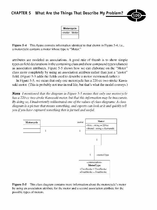
CHAPTER 5 What Are the Things That Describe My Problem?
Figure 5-4 This figure conveys information identical to that shown in Figure 5-4; i.e.,a motorcycle contains a motor whose type is "Motor."
attributes are modeled as associations. A good rule of thumb is to show simpletypes as field declarations in the containing class and show compound types (classes)as association attributes. Figure 5-5 shows how we can elaborate on the "Motor"class more completely by using an association attribute rather than just a "motor"field. (Figure 5-5 adds the fields used to describe a motor mentioned earlier.)
In Figure 5-5, we mean that only one motorcycle has a 220-cc two-stroke Kawa-saki motor. (This is probably not true in real life, but that's what the model conveys.)
NOTE I mentioned that the diagram in Figure 5-5 means that only one motorcyclehas a 220-cc two-stroke Kawasaki motor, but that this information may be inaccurate.By doing so, I inadvertently reillustrated one of the values of class diagrams: A classdiagram is a picture that means something, and experts can look at it and quickly tellyou if you have captured something that is factual and useful.
Figure 5-5 This class diagram contains more information about the motorcycle's motorby using an association attribute for the motor and a second association attribute for thepossible types of motors.
109;
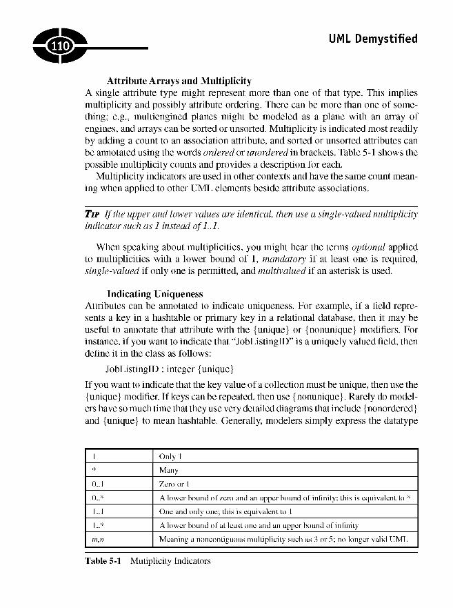
UML Demystified
Attribute Arrays and MultiplicityA single attribute type might represent more than one of that type. This impliesmultiplicity and possibly attribute ordering. There can be more than one of some-thing; e.g., multiengined planes might be modeled as a plane with an array ofengines, and arrays can be sorted or unsorted. Multiplicity is indicated most readilyby adding a count to an association attribute, and sorted or unsorted attributes canbe annotated using the words ordered or unordered in brackets. Table 5-1 shows thepossible multiplicity counts and provides a description for each.
Multiplicity indicators are used in other contexts and have the same count mean-ing when applied to other UML elements beside attribute associations.
TIP If the upper and lower values are identical, then use a single-valued multiplicityindicator such as 1 instead ofL.l.
When speaking about multiplicities, you might hear the terms optional appliedto multiplicities with a lower bound of 1, mandatory if at least one is required,single-valued if only one is permitted, and multivalued if an asterisk is used.
Indicating UniquenessAttributes can be annotated to indicate uniqueness. For example, if a field repre-sents a key in a hashtable or primary key in a relational database, then it may beuseful to annotate that attribute with the {unique} or {nonunique} modifiers. Forinstance, if you want to indicate that "JobListingID" is a uniquely valued field, thendefine it in the class as follows:
-JobListingID : integer {unique}
If you want to indicate that the key value of a collection must be unique, then use the{unique} modifier. If keys can be repeated, then use {nonunique}. Rarely do model-ers have so much time that they use very detailed diagrams that include {nonordered}and {unique} to mean hashtable. Generally, modelers simply express the datatype
Table 5-1 Mutiplicity Indicators
110
1 Only 1
* Many
0..1 Zero or 1
0..* A lower bound of zero and an upper bound of infinity; this is equivalent to *
1..1 One and only one; this is equivalent to 1
1 ..* A lower bound of at least one and an upper bound of infinity
m,n Meaning a noncontiguous multiplicity such as 3 or 5; no longer valid UML

CHAPTER 5 What Are the Things That Describe My Problem?
of the attribute, but it is worth knowing that the UML specifies ordered versus non-ordered and unique versus nonunique and not array or hashtable. Arrays and hashtablesrepresent known design solutions, not aspects of the UML language.
Adding Operations to ClassesIt can be useful to think of modeling as something that cycles from a high-levelmacro view to successively lower-level micro views and ultimately to code, themost detailed micro view. The macro phase can be thought of as an analysis phase.During this phase, it might be enough to capture classes and relationships as youbegin to understand the problem space. As your understanding improves and youbegin to capture the details of a solution—moving from a macro understanding to amore detailed micro understanding—you begin elaborating on a design. At thisjuncture you may return to your class diagrams and begin adding operations andattributes. Operations, behaviors, and methods all refer to the same thing. In theUML, we generally say operation, and when coding, we generally say method.
Operations are shown in the bottom-most rectangle of a classifier. Operationshave a visibility modifier such as attributes. Operations include a return datatype; aname; a parameter list including names, datatypes, and modifiers; and additionalmodifiers that may indicate if an operation is static, virtual, or something else.
As mentioned previously, it isn't necessary to show property methods. You alsocan save yourself some time by not elaborating on nonpublic operations in greatdetail. The public operations generally will describe the behaviors of the class suffi-ciently, and the nonpublic members can be left to the devices of your programmers.
Since I don't actually have an application that represents motorcycles or a vehi-cle inventory for a motor sports vehicle store, let's change the examples a bit.Occasionally, I go to Las Vegas and partake in a little "Blackjack" (Figure 5-6).Because I like to get as much entertainment as possible for my money, I wanted topractice "Blackjack" in a way that would make me a better player. Hence I wrote a"Blackjack" game that provided tips based on the best course of action to win ahand. (This application is done, and the code is online at www.softconcepts.com.) Inthat example, there are many classes, including a class that represents a player'shand as a list of cards. Some of the operation signatures used to implement the"Hand" class are shown in the classifier in Figure 5-7.
Modeling Relationships in Class DiagramsClass diagrams consist primarily of classifiers with attributes and operations and con-nectors that describe the relationships between classes. About 80 percent of your classdiagrams will just use these features. However, while this sounds simple, class
:inj
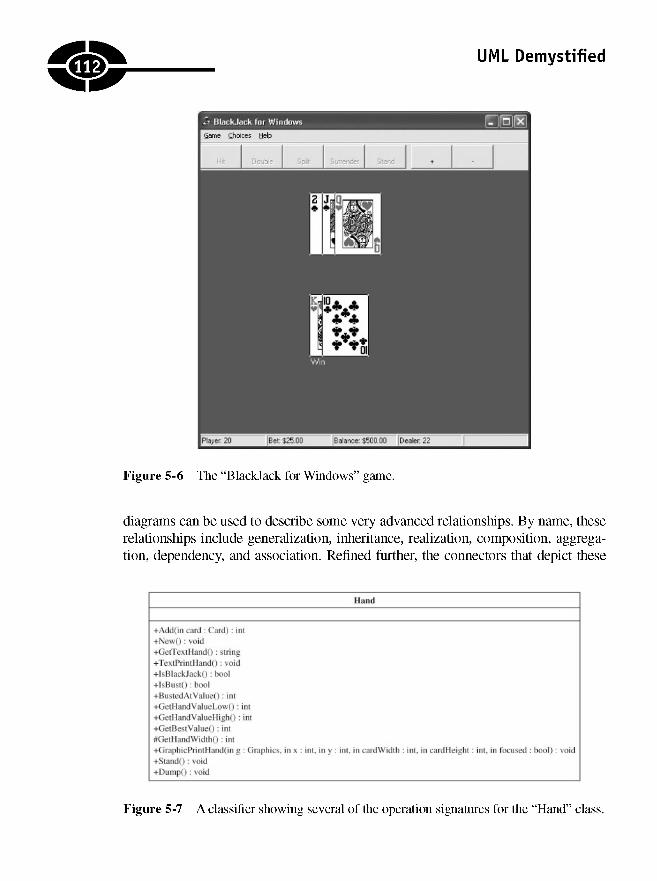
UML Demystified
Figure 5-6 The "Blackjack for Windows" game.
diagrams can be used to describe some very advanced relationships. By name, theserelationships include generalization, inheritance, realization, composition, aggrega-tion, dependency, and association. Refined further, the connectors that depict these
Figure 5-7 A classifier showing several of the operation signatures for the "Hand" class.
ji2:
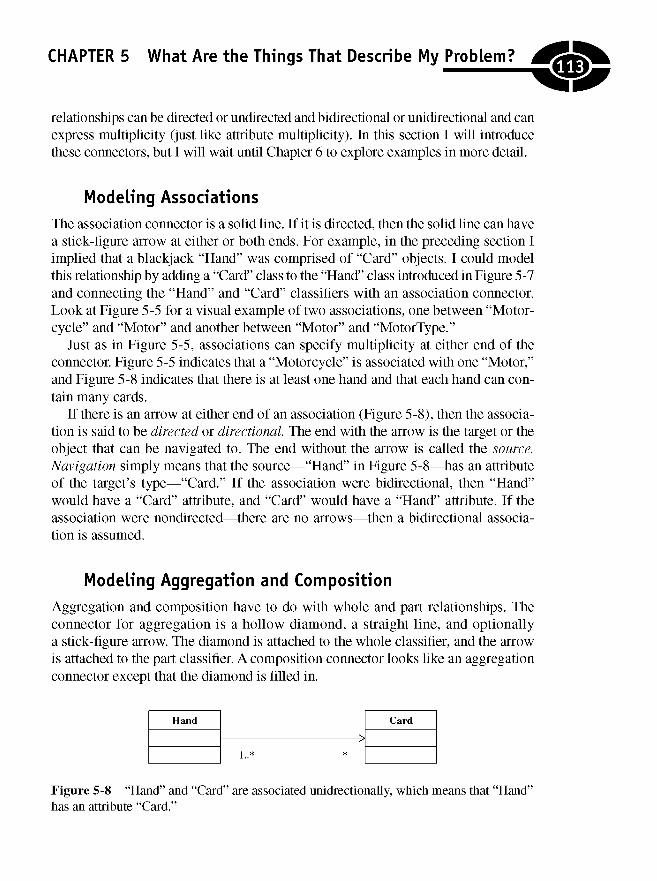
CHAPTER 5 What Are the Things That Describe My Problem?
relationships can be directed or undirected and bidirectional or unidirectional and canexpress multiplicity (just like attribute multiplicity). In this section I will introducethese connectors, but I will wait until Chapter 6 to explore examples in more detail.
Modeling Associations
The association connector is a solid line. If it is directed, then the solid line can havea stick-figure arrow at either or both ends. For example, in the preceding section Iimplied that a blackjack "Hand" was comprised of "Card" objects. I could modelthis relationship by adding a "Card" class to the "Hand" class introduced in Figure 5-7and connecting the "Hand" and "Card" classifiers with an association connector.Look at Figure 5-5 for a visual example of two associations, one between "Motor-cycle" and "Motor" and another between "Motor" and "MotorType."
Just as in Figure 5-5, associations can specify multiplicity at either end of theconnector. Figure 5-5 indicates that a "Motorcycle" is associated with one "Motor,"and Figure 5-8 indicates that there is at least one hand and that each hand can con-tain many cards.
If there is an arrow at either end of an association (Figure 5-8), then the associa-tion is said to be directed or directional. The end with the arrow is the target or theobject that can be navigated to. The end without the arrow is called the source.Navigation simply means that the source—"Hand" in Figure 5-8—has an attributeof the target's type—"Card." If the association were bidirectional, then "Hand"would have a "Card" attribute, and "Card" would have a "Hand" attribute. If theassociation were nondirected—there are no arrows—then a bidirectional associa-tion is assumed.
Modeling Aggregation and Composition
Aggregation and composition have to do with whole and part relationships. Theconnector for aggregation is a hollow diamond, a straight line, and optionallya stick-figure arrow. The diamond is attached to the whole classifier, and the arrowis attached to the part classifier. A composition connector looks like an aggregationconnector except that the diamond is filled in.
Figure 5-8 "Hand" and "Card" are associated unidrectionally, which means that "Hand"has an attribute "Card."
<&
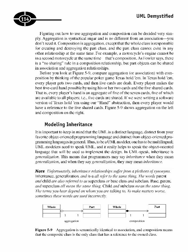
UML Demystified
Figuring out how to use aggregation and composition can be decided very sim-ply. Aggregation is syntactical sugar and is no different from an association—youdon't need it. Composition is aggregation, except that the whole class is responsiblefor creating and destroying the part class, and the part class cannot exist in anyother relationship at the same time. For example, a motorcycle's engine cannot bein a second motorcycle at the same time—that's composition. As Fowler says, thereis a "no sharing" rule in a composition relationship, but part objects can be sharedin association and aggregation relationships.
Before you look at Figure 5-9, compare aggregation (or association) with com-position by thinking of the popular poker game Texas hold 'em. In Texas hold 'em,every player gets two cards, and then five cards are dealt. Every player makes thebest five-card hand possible by using his or her two cards and the five shared cards.That is, every player's hand is an aggregate of five of the seven cards, five of whichare available to all players; i.e., five cards are shared. If we were writing a softwareversion of Texas hold 'em using our "Hand" abstraction, then every player wouldhave a reference to the five shared cards. Figure 5-9 shows aggregation on the leftand composition on the right.
Modeling Inheritance
It is important to keep in mind that the UML is a distinct language, distinct from yourfavorite object-oriented programming language and distinct from object-oriented pro-gramming languages in general. Thus, to be a UML modeler, one has to be multilingual;UML modelers need to speak UML, and it really helps to speak the object-orientedlanguage that will be used to implement the design. In UML-speak, inheritance isgeneralization. This means that programmers may say inheritance when they meangeneralization, and when they say generalization, they may mean inheritance.
NOTE Unfortunately, inheritance relationships suffer from a plethora of synonyms.Inheritance, generalization, and is-a all refer to the same thing. The words parentand child are also referred to as superclass or base class and subclass. Base, parent,and superclass all mean the same thing. Child and subclass mean the same thing.The terms you hear depend on whom you are talking to. To make matters worse,sometimes these words are used incorrectly.
Figure 5-9 Aggregation is semantically identical to association, and composition meansthat the composite class is the only class that has a reference to the owned class.
114J
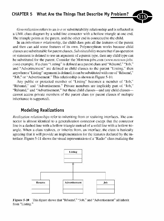
CHAPTER 5 What Are the Things That Describe My Problem?
Generalization refers to an is-a or substitutability relationship and is reflected ina UML class diagram by a solid line connector with a hollow triangle at one end.The triangle points at the parent, and the other end is connected to the child.
In an inheritance relationship, the child class gets all the features of the parentand then can add some features of its own. Polymorphism works because childclasses are substitutable for parent classes. Substitutability means that if an operationor statement is defined to use an argument of a parent type, then any child type canbe substituted for the parent. Consider the Motown-jobs.com (www.motown-jobs.com) example. If a class "Listing" is defined as a parent class and "Resume," "Job,"and "Advertisement" are defined as child classes to the parent "Listing," thenanywhere a "Listing" argument is defined, it can be substituted with one of "Resume,""Job," or "Advertisement." This relationship is shown in Figure 5-10.
Any public or protected member of "Listing" becomes a member of "Job,""Resume," and "Advertisement." Private members are implicitly part of "Job,""Resume," and "Advertisement," but these child classes—and any child classes—cannot access private members of the parent class (or parent classes if multipleinheritance is supported).
Modeling Realizations
Realization relationships refer to inheriting from or realizing interfaces. The con-nector is almost identical to a generalization connector except that the connectorline is a dashed line with a hollow triangle instead of a solid line with a hollow tri-angle. When a class realizes, or inherits from, an interface, the class is basicallyagreeing that it will provide an implementation for the features declared by the in-terface. Figure 5-11 shows the visual representation of a "Radio" class realizing the
Figure 5-10 This figure shows that "Resume," "Job," and "Advertisement" all inheritfrom "Listing."
115]
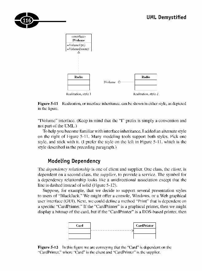
UML Demystified
Figure 5-11 Realization, or interface inheritance, can be shown in either style, as depictedin the figure.
"IVolume" interface. (Keep in mind that the "I" prefix is simply a convention andnot part of the UML.)
To help you become familiar with interface inheritance, I added an alternate styleon the right of Figure 5-11. Many modeling tools support both styles. Pick onestyle, and stick with it. (I prefer the style on the left in Figure 5-11, which is thestyle described in the preceding paragraph.)
Modeling Dependency
The dependency relationship is one of client and supplier. One class, the client, isdependent on a second class, the supplier, to provide a service. The symbol fora dependency relationship looks like a unidirectional association except that theline is dashed instead of solid (Figure 5-12).
Suppose, for example, that we decide to support several presentation stylesto users of "Blackjack." We might offer a console, Windows, or a Web graphicaluser interface (GUI). Next, we could define a method "Print" that is dependent ona specific "CardPrinter." If the "CardPrinter" is a graphical printer, then we mightdisplay a bitmap of the card, but if the "CardPrinter" is a DOS-based printer, then
Figure 5-12 In this figure we are conveying that the "Card" is dependent on the"CardPrinter," where "Card" is the client and "CardPrinter" is the supplier.
lie:
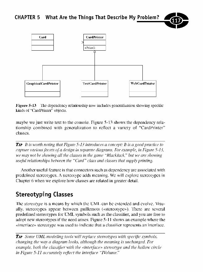
CHAPTER 5 What Are the Things That Describe My Problem?
Figure 5-13 The dependency relationship now includes generalization showing specifickinds of "CardPrinter" objects.
maybe we just write text to the console. Figure 5-13 shows the dependency rela-tionship combined with generalization to reflect a variety of "CardPrinter"classes.
TIP It is worth noting that Figure 5-13 introduces a concept: It is a good practice tocapture various facets of a design in separate diagrams. For example, in Figure 5-13,we may not be showing all the classes in the game "Blackjack," but we are showinguseful relationships between the "Card" class and classes that supply printing.
Another useful feature is that connectors such as dependency are associated withpredefined stereotypes. A stereotype adds meaning. We will explore stereotypes inChapter 6 when we explore how classes are related in greater detail.
Stereotyping ClassesThe stereotype is a means by which the UML aan be extended and evolve. Visu-ally, stereotypes appear between guillemots («stereotype»). There are severalpredefined stereotypes for UML symbols such as the classifier, and you are free toadopt new stereotypes if the need arises. Figure 5-11 shows an example where the«interface» stereotype was used to indicate that a classifier represents an interface.
TIP Some UML modeling tools will replace stereotypes with specific symbols,changing the way a diagram looks, although the meaning is unchanged. Forexample, both the classifier with the «interface» stereotype and the hollow circlein Figure 5-11 accurately reflect the interface "IVolume."
117J
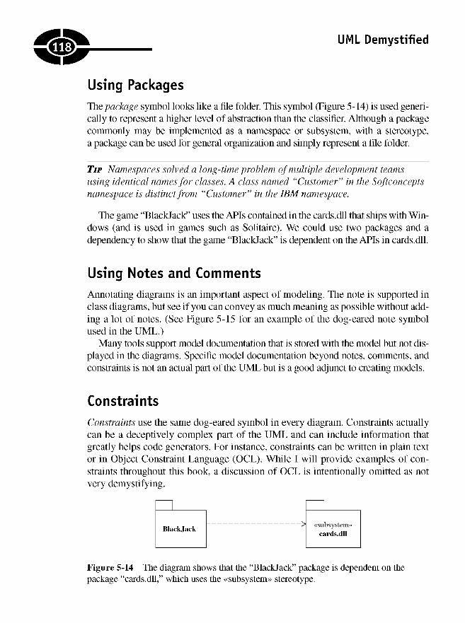
UML Demystified
Using PackagesThe package symbol looks like a file folder. This symbol (Figure 5-14) is used generi-cally to represent a higher level of abstraction than the classifier. Although a packagecommonly may be implemented as a namespace or subsystem, with a stereotype,a package can be used for general organization and simply represent a file folder.
TIP Namespaces solved a long-time problem of multiple development teamsusing identical names for classes. A class named "Customer" in the Softconceptsnamespace is distinct from "Customer" in the IBM namespace.
The game "Blackjack" uses the APIs contained in the cards.dll that ships with Win-dows (and is used in games such as Solitaire). We could use two packages and adependency to show that the game "Blackjack" is dependent on the APIs in cards.dll.
Using Notes and CommentsAnnotating diagrams is an important aspect of modeling. The note is supported inclass diagrams, but see if you can convey as much meaning as possible without add-ing a lot of notes. (See Figure 5-15 for an example of the dog-eared note symbolused in the UML.)
Many tools support model documentation that is stored with the model but not dis-played in the diagrams. Specific model documentation beyond notes, comments, andconstraints is not an actual part of the UML but is a good adjunct to creating models.
ConstraintsConstraints use the same dog-eared symbol in every diagram. Constraints actuallycan be a deceptively complex part of the UML and can include information thatgreatly helps code generators. For instance, constraints can be written in plain textor in Object Constraint Language (OCL). While I will provide examples of con-straints throughout this book, a discussion of OCL is intentionally omitted as notvery demystifying.
Figure 5-14 The diagram shows that the "Blackjack" package is dependent on thepackage "cards.dll," which uses the «subsystem» stereotype.
.118.
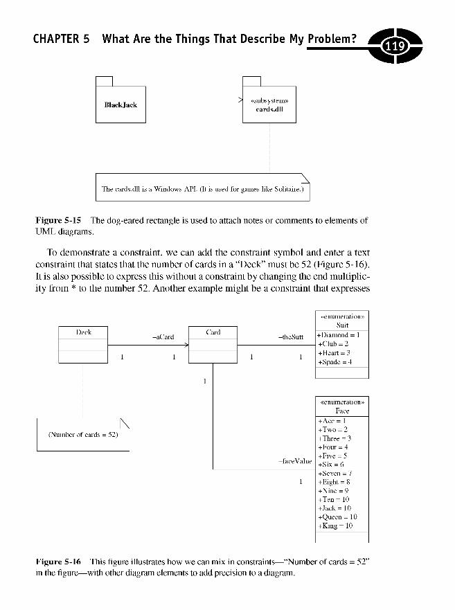
CHAPTER 5 What Are the Things That Describe My Problem?
Figure 5-15 The dog-eared rectangle is used to attach notes or comments to elements ofUML diagrams.
To demonstrate a constraint, we can add the constraint symbol and enter a textconstraint that states that the number of cards in a "Deck" must be 52 (Figure 5-16).It is also possible to express this without a constraint by changing the end multiplic-ity from * to the number 52. Another example might be a constraint that expresses
Figure 5-16 This figure illustrates how we can mix in constraints—"Number of cards = 52"in the figure—with other diagram elements to add precision to a diagram.
llg)

UML Demystified
Figure 5-17 The class diagram from Figure 5-16 modified to capture the fact that cardscan have dynamic face values.
something about the face value or the number and variety of suits, and we alsocould express these elements with enumerations.
In Figure 5-16,1 included the constraint that the number of cards in a "Deck" hasto be 52, an enumeration to indicate that there are four suits, and an enumeration toindicate that there are 14 possible unique face values. Unfortunately, the figure stillfalls short because in the game "Blackjack," the ace does not have a unique, singlevalue. An analysis of this model with a domain expert might quickly reveal a pos-sible problem with using an enumeration for "Face." Because of the dual value ofthe ace, we may elect to redesign the solution to use a class—"Face"—and a gen-eralization—specific face values, such as "Ace," "Two," "Three," etc.—to fix theproblem with aces (Figure 5-17).
Modeling PrimitivesThe UML defines primitives such as "Integer," "Boolean," "String," and "Unlimited-Natural" for use in the UML specification, but most languages and tools define theirown primitive types. You can model primitives using a classifier, the «primitive»stereotype, and the name of the type.
120
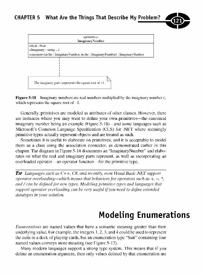
CHAPTER 5 What Are the Things That Describe My Problem?
Figure 5-18 Imaginary numbers are real numbers multiplied by the imaginary number i,which represents the square root of-1.
Generally, primitives are modeled as attributes of other classes. However, thereare instances where you may want to define your own primitives—the canonicalimaginary number being an example (Figure 5-18)—and some languages such asMicrosoft's Common Language Specification (CLS) for .NET where seeminglyprimitive types actually represent objects and are treated as such.
Sometimes it is useful to elaborate on primitives, and it is acceptable to modelthem as a class using the association connector, as demonstrated earlier in thischapter. The diagram in Figure 5-18 documents an "ImaginaryNumber" and elabo-rates on what the real and imaginary parts represent, as well as incorporating anoverloaded operator—an operator function—for the primitive type.
TIP Languages such as C++, C#, and recently, even Visual Basic.NET supportoperator overloading—which means that behaviors for operators such as +, -, *,and/ can be defined for new types. Modeling primitive types and languages thatsupport operator overloading can be very useful if you need to define extendeddatatypes in your solution.
Modeling EnumerationsEnumerations are named values that have a semantic meaning greater than theirunderlying value. For example, the integers 1,2,3, and 4 could be used to representthe suits in a deck of playing cards, but an enumeration type "Suit" containing fournamed values conveys more meaning (see Figure 5-17).
Many modern languages support a strong type system. This means that if youdefine an enumeration argument, then only values defined by that enumeration are
12f
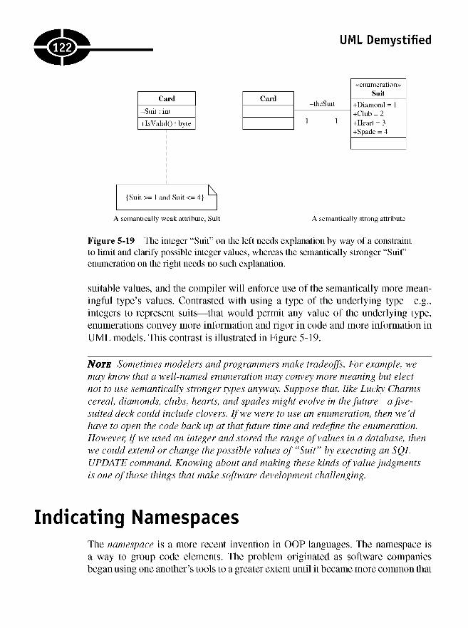
UML Demystified
Figure 5-19 The integer "Suit" on the left needs explanation by way of a constraintto limit and clarify possible integer values, whereas the semantically stronger "Suit"enumeration on the right needs no such explanation.
suitable values, and the compiler will enforce use of the semantically more mean-ingful type's values. Contrasted with using a type of the underlying type—e.g.,integers to represent suits—that would permit any value of the underlying type,enumerations convey more information and rigor in code and more information inUML models. This contrast is illustrated in Figure 5-19.
NOTE Sometimes modelers and programmers make tradeoffs. For example, wemay know that a well-named enumeration may convey more meaning but electnot to use semantically stronger types anyway. Suppose that, tike Lucky Charmscereal, diamonds, clubs, hearts, and spades might evolve in the future—a five-suited deck could include clovers. If we were to use an enumeration, then we'dhave to open the code back up at that future time and redefine the enumeration.However, if we used an integer and stored the range of values in a database, thenwe could extend or change the possible values of "Suit" by executing an SQLUPDATE command. Knowing about and making these kinds of value judgmentsis one of those things that make software development challenging.
Indicating NamespacesThe namespace is a more recent invention in OOP languages. The namespace isa way to group code elements. The problem originated as software companiesbegan using one another's tools to a greater extent until it became more common that
.1221
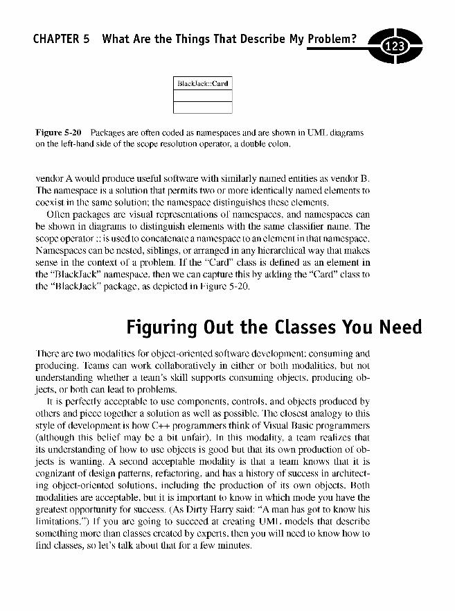
CHAPTER 5 What Are the Things That Describe My Problem?
Figure 5-20 Packages are often coded as namespaces and are shown in UML diagramson the left-hand side of the scope resolution operator, a double colon.
vendor A would produce useful software with similarly named entities as vendor B.The namespace is a solution that permits two or more identically named elements tocoexist in the same solution; the namespace distinguishes these elements.
Often packages are visual representations of namespaces, and namespaces canbe shown in diagrams to distinguish elements with the same classifier name. Thescope operator:: is used to concatenate a namespace to an element in that namespace.Namespaces can be nested, siblings, or arranged in any hierarchical way that makessense in the context of a problem. If the "Card" class is defined as an element inthe "Blackjack" namespace, then we can capture this by adding the "Card" class tothe "Blackjack" package, as depicted in Figure 5-20.
Figuring Out the Classes You NeedThere are two modalities for object-oriented software development: consuming andproducing. Teams can work collaboratively in either or both modalities, but notunderstanding whether a team's skill supports consuming objects, producing ob-jects, or both can lead to problems.
It is perfectly acceptable to use components, controls, and objects produced byothers and piece together a solution as well as possible. The closest analogy to thisstyle of development is how C++ programmers think of Visual Basic programmers(although this belief may be a bit unfair). In this modality, a team realizes thatits understanding of how to use objects is good but that its own production of ob-jects is wanting. A second acceptable modality is that a team knows that it iscognizant of design patterns, refactoring, and has a history of success in architect-ing object-oriented solutions, including the production of its own objects. Bothmodalities are acceptable, but it is important to know in which mode you have thegreatest opportunity for success. (As Dirty Harry said: "A man has got to know hislimitations.") If you are going to succeed at creating UML models that describesomething more than classes created by experts, then you will need to know how tofind classes, so let's talk about that for a few minutes.
123

UML Demystified
NOTE In 2005, author Richard Mansfield, in an editorial posted on DevX.com,challenged OO as a valid paradigm. All jokes about old dogs and new tricksaside, Mansfield made a point accidentally. The point is that if you know OO wellenough to consume it but try to produce it, then OO likely will be disappointing.I suspect that many OO projects fail because accomplished OO consumers are notso accomplished OO producers. Producing quality objects is difficult at best, andwithout extemporaneous knowledge of patterns, refactoring, and experience, goodOO may be impossible to produce.
Finding the right classes is the hardest thing you will do. Finding the right classesis much harder than drawing the diagrams. If you find the right classes, then napkinsare sufficient for modeling. If you can't find the right classes, then no matter howmuch money you spend on tools, your designs probably will result in failedimplementations.
Using the Naive Approach
When I learned about OO, it was by teaching myself C++ first, a very painful pro-cess, and then I got around to reading about OO. The first thing I learned was thatit was a matter of finding the nouns and then assigning verbs to the nouns. Thenouns became classes and the verbs methods. This is the easy part, but it probablywill yield only about 20 percent of the classes you will need.
If analysis leads to just the nouns and verbs described by the domain, then therewill be a shortfall of classes, and much hacking will ensue. Beginning with thenouns and verbs of the domain is a good start, though.
Discovering More than Domain Analysis Yields
In addition to the things that your customers' experts tell you, you also will need tofigure out how to make these things available to your customers and in almost allcircumstances save the information that users provide. These pieces of informationare referred to genetically as boundary, control, and entity classes. A boundaryclass is a class used to connect elements outside the system with elements inside.Entity classes represent data. Typically, entities represent persisted data such as youmight find in a database, and control classes manage or act on other classes. Userstypically tell you a lot about entity classes and can help define GUIs based on howthey complete tasks, but you have to work harder to find control and boundaryclasses.
.124J
CHAPTER 5 What Are the Things That Describe My Problem?
TIP If you ever work as an analyst, don't say, "You have told me about the entityclasses; now tell me about the boundary classes." Analysis is an important taskand probably should not be left to those with pencil protectors in their vest pockets.Interpersonal skills and a low-tech, conversational approach elicit a good exchangeof ideas.
An important perspective is to know that business experts will tell you a lot aboutthe data they have to store, some about the processes they follow to get the data, anda little about a good way to get that data into a computer. A second important per-spective is that users—the ones assigned to explain things to software engineers arecalled domain experts—may do a lot of things that don't make any sense to outsid-ers. From a rational point of view, this means that a process engineer may havenever worked with his or her organization to examine what the organization doesand how it does it and to determine if there is a better way to do it. The result is thatyou may get a lot of information that may not translate well to software—calleda low signal-to-noise ratio—but the domain expert may feel it is important.
TIP When it comes to analysis, the best advice I can offer is to buy an expensivepen and a leather-bound notebook, engage actively in the conversation, and takecopious notes. In addition to users being flattered that so much lavish attention isbeing paid to them, it is difficult to know early in analysis what constitutes signaland what constitutes noise, so a lot of information is good.
Having learned about the entity classes from users, your job is to figure out whatthe control and boundary classes are and how to model these things. The modelingis easiest, so let's start there.
Quite simply, an entity class is data and usually is long-lived or persisted, andentity classes can be modeled by adding the «entity» stereotype to the class symbolor using the entity class symbol available in many modeling tools (Figure 5-21). Acontrol class is transient code that generally controls or acts on other classes and isresponsible for transporting data between entity classes and boundary classes. Con-trol classes are modeled by adding the «control» stereotype to a class or by usingthe class symbol (also shown in Figure 5-21). Boundary classes usually are foundbetween subsystems. Boundary classes can be modeled as shown in Figure 5-21 orby adorning a class with the «boundary» stereotype.
A Nod to CRC Exercises
Class responsibility and collaborator (CRC) cards is a concept that involves a low-tech use of 3 x 5 index cards. The idea is that a group of interested people get
125
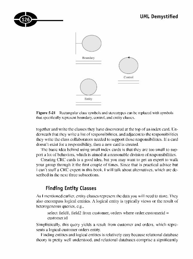
UML Demystified
Figure 5-21 Rectangular class symbols and stereotypes can be replaced with symbolsthat specifically represent boundary, control, and entity classes.
together and write the classes they have discovered at the top of an index card. Un-derneath that they write a list of responsibilities, and adjacent to the responsibilitiesthey write the class collaborators needed to support those responsibilities. If a carddoesn't exist for a responsibility, then a new card is created.
The basic idea behind using small index cards is that they are too small to sup-port a lot of behaviors, which is aimed at a reasonable division of responsibilities.
Creating CRC cards is a good idea, but you may want to get an expert to walkyour group through it the first couple of times. Since that is practical advice butI can't stuff a CRC expert in this book, I will talk about alternatives, which are de-scribed in the next three subsections.
Finding Entity Classes
As I mentioned earlier, entity classes represent the data you will need to store. Theyalso encompass logical entities. A logical entity is typically views or the result ofheterogeneous queries, e.g.,
select fieldl, field2 from customer, orders where order.customerid =customer.id
Simplistically, this query yields a result from customer and orders, which repre-sents a logical customer orders entity.
Finding entities and logical entities is relatively easy because relational databasetheory is pretty well understood, and relational databases comprise a significantly
126J
CHAPTER 5 What Are the Things That Describe My Problem?
recurring repository for entities. You will need entities for single tables and hetero-geneous views comprised of multiple tables. From that point on, the entities aresimply modeled as classes. You can use a «table» stereotype if the entities representtables or no particular stereotype if you use custom classes.
Finding Control Classes
Control classes represent the bridge between entity classes and boundary classesand business logic in between. How you implement these classes depends on yourimplementation style. If you pick an implementation style, then finding entityclasses can be derived from there.
Suppose that your implementation tool of choice predefines classes such as rows,tables, and datasets. If you elect to use your tool's classes, then your entity classeswill be composed of those classes, and the classes that bridge to your entity classeswill be defined by your tool's framework. On the other hand, if you pick customentity classes, then your entity classes will be analogues to rows, tables, and data-sets, but the control classes will still be framework classes that read and write to andfrom your persistence store, usually a database.
Control classes can mange how data are marshaled to entity classes, how data aremarshaled to presentation classes, and how data are marshaled to other systemsthrough boundary classes. There are many patterns that include general control pat-terns; the key is to recognize them. A famous pattern is called model view controller(MVC). In MVC, the model is represented by business objects, the GUI is yourview, and control classes in between represent your controller. Implementing MVCor recognizing an implementation of MVC requires further study and practice. Forexample, Microsoft considers the ASP.NET pages in .NET to be an implementationof MVC. The ASPX or HTML page is the view, the controller is the code-behindpage, and the model is the objects whose data are shown on the page. Implementinga custom MVC pattern in this context would be redundant. There are many bookson patterns; Design Patterns (Reading, MA: Addison-Wesley, 1995) by Erich Gammais a good place to start.
NOTE There are many design patterns that can guide you when searching forboundary, control, and entity classes. A key here is to pick an implementationstyle and stick with it. You can compose a solution by finding entities first—calleddatabase composition—or by finding business objects—called object composition—or by designing GUIs first—called presentation composition or sometimes referredto as hacking. Any of these composition styles can be successful, but some styleswork better than others depending on the size and complexity of the problem.Unfortunately, there is no single best style for all circumstances, and opinions varygreatly on this subject.
127]

UML Demystified
Finding Boundary Classes
Boundary classes are used to bridge subsystems. The objective here is to insulateyour system from direct interaction with external subsystems. In this way, if theexternal subsystem changes, your implementation will only need to change in theboundary classes. A good knowledge of patterns and a study of successful systemscan help here.
This book is about the UML and is not intended to be a how-to book on softwaredesign. However, a scan of the Bibliography will lead you to some excellent bookson UML and software design.
Quiz1. The same basic symbol is used for interfaces and classes.
a. True
b. false
2. When adding classes to a diagram, you should
a. show properties, fields, and methods.
b. show properties and fields only.
c. show properties and methods.
d. show fields and methods.
3. An attribute can be modeled as a feature of a class but not as an associationclass.
a. True
b. False
4. When modeling attributes, it is
a. required that you model attribute methods.
b. recommended that you not show attribute methods.
c. recommended that you show the underlying fields for those attributes.
d. None of the above
5. Both simple types and complex types should be modeled as
a. attributes.
b. association classes.
IKM
CHAPTER 5 What Are the Things That Describe My Problem?
c. attributes and association classes.
d. Simple types are best modeled as attributes, and complex types are bestmodeled as associations.
6. A unidirectional association has an arrow at one end called the source. Theother end is called the target.
a. The source will have a field whose type is the type of the target.
b. The target will have a field whose type is the source.
c. Neither
7. Are an aggregation and association
a. semantically similar?
b. directly opposite?
8. What is the most important difference between an aggregation and acomposition?
a. Composition means that the whole, or composite, class will beresponsible for creating and destroying the part or contained class.
b. Aggregation means that the whole aggregate class will be responsiblefor creating and destroying the part or contained class.
c. Composition means that the whole, or composite, class is the only classthat can have an instance of the part class at any given time.
d. Aggregation means that the whole, or aggregate, class is the only classthat can have an instance of the part class at any given time.
e. a and c
f. b and d
9. Generalization means
a. polymorphism.
b. association.
c. inheritance.
d. composition.
10. An association is named. The name is
a. the type of the associated class.
b. the implied name of the association and represents a field name.
c. a dependency.
d. a generalization.
129J
UML Demystified
11. The «primitive» is used in conjunction with the class symbol. It introduces
a. existing simple types.
b. new semantically simple types.
c. existing complex types.
d. new semantically complex types.
Answers1. a
2. d
3. b
4. b
5. a
6. a
7. e
8. c
9. b
10. b
11. b
130)
CHAPTER
Showing HowClasses Are
Related
Chapter 5 introduced class diagrams as static views of your system. By static view,I mean that classes just lie there, but your classes define the things that are used toexplore dynamic behaviors described in interaction diagrams and state charts.
Because classes and class diagrams contain elements central to your system,I will expand on the basic use of symbols and basic relationships from Chapter 5.This chapter will explore more advanced relationships and more detailed classinformation by looking at
• Diagrams with a greater number of elements
• Annotated relationships, including multiplicity
• Modeling abstract classes and interfaces
6
i3i;
Copyright © 2005 by The McGraw-Hill Companies. Click here for terms of use.

UML Demystified
• Adding details to class diagrams
• Comparing classification to generalization
Modeling InheritanceThere are benefits to inheritance as well as challenges. A child class inherits all thefeatures of its parent class. When an attribute is defined in a parent class, it is incor-rect to repeat the attribute in child classes. If you repeat a method in a child class,then you are describing method overriding. In addition to overriding, you can rede-fine methods in the Unified Modeling Language (UML), and it is supported in somelanguages but can lead to confusion. Method overriding is central to polymorphism;use operation redefinition sparingly.
When you inherit classes, your child classes inherit the constraints defined by allancestors. Each element has the union of the constraints it defines and constraintsdefined by its ancestors.
You have several inheritance options that I will explain in this section. This sectionwill look at single inheritance and multiple inheritance and compare generalizationwith classification. To avoid deep inheritance trees, I also will explain interface inheri-tance and composition in the two sections that follow.
Using Single Inheritance
Single inheritance is the easiest form of inheritance. A child class that inherits froma parent class inherits all the features of the parent class but only has direct accessto public and protected members. Inheritance, called generalization in the UML, isindicated by a single line extending from the child to the parent with a hollow tri-angle attached to the parent. If multiple classes inherit from the same parent, thenyou can use a single, merged line connecting to the parent.
Generalization versus Classification
In Chapter 5 I introduced an easy test to determine if an inheritance relationshipexists. This is called the is-a test. This test alone can be misleading and result inincorrect results. Is-a implies strict transitivity. For example, if class B is a child ofclass A and class C is a child of class B, then class C is a child of class A. (We say thatclass C is a grandchild of class A or class A is an ancestor of class C.) However, thetransitivity implied by the is-a test is not strictly correct.
132;

CHAPTER 6 Showing How Classes Are Related
Suppose that we have the following true statements:
Paul is a C# Programmer.C# Programmer is a Job Description.Paul is a Person.C# Programmer is a Person.
"Paul is a C# Programmer" works. "A C# Programmer is a Person" works, and "C#Programmer is a Job Description" works, but "Paul is a Job Description" does notwork. The problem is that Paul is an instance of C# Programmer. This relationship isdescribed as a classification of Paul the C# Programmer, but generalization (i.e., in-heritance) is used to describe relationships between subtypes. Therefore, be carefulwhen using is-a as a sole determinant of inheritance. A more precise test is to deter-mine if something describes an instance (classification) or a subtype (generalization).
If class B is a subtype of class A, then you have inheritance. If the relationshipdescribes a classification—i.e., describes a context or role in which something istrue—then you have a classification relationship. Classifications can be better man-aged with associations.
Dynamic Classification
The preceding discussion suggests that inheritance is sometimes misapplied.Returning to our example, Paul is-a programmer describes a role, or classification,more precisely than a generalization because Paul is also a husband, father, andtaxpayer. If we tried to generalize Paul as all those things through inheritance, we'dhave to use multiple inheritance, and the relationships would be pretty complex.
The way to model and capture classification is through association. In fact, wecan use a state behavior pattern to capture the dynamic and changing roles thatdescribe a person or how the instance Paul behaves in a given context. Usingassociation and, more specifically, the state behavior pattern, we can implementdynamic classification. That is, we can change Paul's behavior based on the contextor the role he is playing at a given moment.
The state behavior pattern is implemented using an association and generalization.Without trying to reproduce the entire discussion on this pattern—refer to DesignPatterns, by Erich Gamma et al.—we can summarize. The state behavior pattern iscalled a behavior pattern because it is a pattern that describes how something acts.The other general kinds of patterns are creational—how something is created—andstructural—how something is organized. The pattern is named the state patternbecause it describes how something behaves based on state. In our example, we woulduse this pattern to describe how people behave based on some condition, the state. Forexample, when Paul is at work, he behaves like a C# programmer. When Paul is at
533)
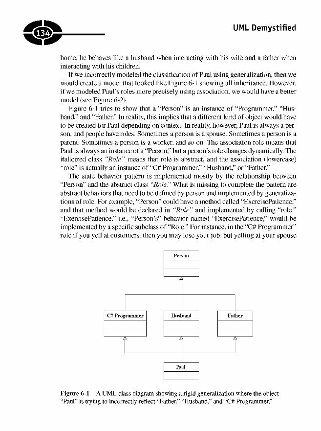
UML Demystified
home, he behaves like a husband when interacting with his wife and a father wheninteracting with his children.
If we incorrectly modeled the classification of Paul using generalization, then wewould create a model that looked like Figure 6-1 showing all inheritance. However,if we modeled Paul's roles more precisely using association, we would have a bettermodel (see Figure 6-2).
Figure 6-1 tries to show that a "Person" is an instance of "Programmer," "Hus-band," and "Father." In reality, this implies that a different kind of object would haveto be created for Paul depending on context. In reality, however, Paul is always a per-son, and people have roles. Sometimes a person is a spouse. Sometimes a person is aparent. Sometimes a person is a worker, and so on. The association role means thatPaul is always an instance of a "Person," but a person's role changes dynamically. Theitalicized class "Role" means that role is abstract, and the association (lowercase)"role" is actually an instance of "C# Programmer," "Husband," or "Father."
The state behavior pattern is implemented mostly by the relationship between"Person" and the abstract class "Role." What is missing to complete the pattern areabstract behaviors that need to be defined by person and implemented by generaliza-tions of role. For example, "Person" could have a method called "ExercisePatience,"and that method would be declared in "Role" and implemented by calling "role.""ExercisePatience," i.e., "Person's" behavior named "ExercisePatience," would beimplemented by a specific subclass of "Role." For instance, in the "C# Programmer"role if you yell at customers, then you may lose your job, but yelling at your spouse
Figure 6-1 A UML class diagram showing a rigid generalization where the object"Paul" is trying to incorrectly reflect "Father," "Husband," and "C# Programmer."
.134
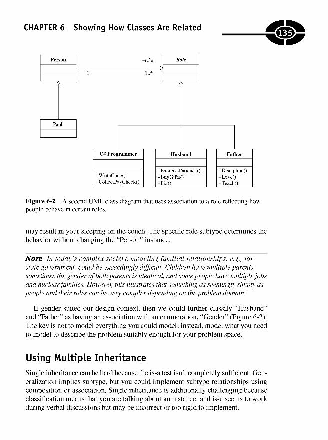
CHAPTER 6 Showing How Classes Are Related
Figure 6-2 A second UML class diagram that uses association to a role reflecting howpeople behave in certain roles.
may result in your sleeping on the couch. The specific role subtype determines thebehavior without changing the "Person" instance.
NOTE In today's complex society, modeling familial relationships, e.g., forstate government, could be exceedingly difficult. Children have multiple parents,sometimes the gender of both parents is identical, and some people have multiple jobsand nuclear families. However, this illustrates that something as seemingly simply aspeople and their roles can be very complex depending on the problem domain.
If gender suited our design context, then we could further classify "Husband"and "Father" as having an association with an enumeration, "Gender" (Figure 6-3).The key is not to model everything you could model; instead, model what you needto model to describe the problem suitably enough for your problem space.
Using Multiple InheritanceSingle inheritance can be hard because the is-a test isn't completely sufficient. Gen-eralization implies subtype, but you could implement subtype relationships usingcomposition or association. Single inheritance is additionally challenging becauseclassification means that you are talking about an instance, and is-a seems to workduring verbal discussions but may be incorrect or too rigid to implement.
.135
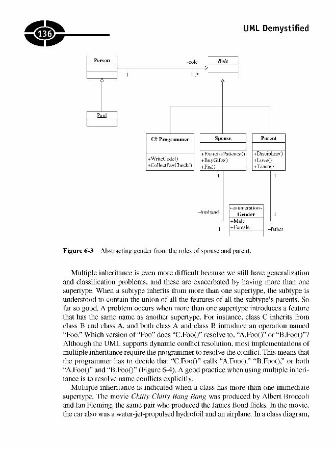
UML Demystified
Figure 6-3 Abstracting gender from the roles of spouse and parent.
Multiple inheritance is even more difficult because we still have generalizationand classification problems, and these are exacerbated by having more than onesupertype. When a subtype inherits from more than one supertype, the subtype isunderstood to contain the union of all the features of all the subtype's parents. Sofar so good. A problem occurs when more than one supertype introduces a featurethat has the same name as another supertype. For instance, class C inherits fromclass B and class A, and both class A and class B introduce an operation named"Foo." Which version of "Foo" does "C.FooO" resolve to, "A.FooO" or "B.FooO"?Although the UML supports dynamic conflict resolution, most implementations ofmultiple inheritance require the programmer to resolve the conflict. This means thatthe programmer has to decide that "C.FooO" calls "A.FooO," "B.FooO," or both"A.FooO" and "B.FooO" (Figure 6-4). A good practice when using multiple inheritance is to resolve name conflicts explicitly.
Multiple inheritance is indicated when a class has more than one immediatesupertype. The movie Chitty Chitty Bang Bang was produced by Albert Broccoliand Ian Fleming, the same pair who produced the James Bond flicks. In the movie,the car also was a water-jet-propulsed hydrofoil and an airplane. In a class diagram,
.we:
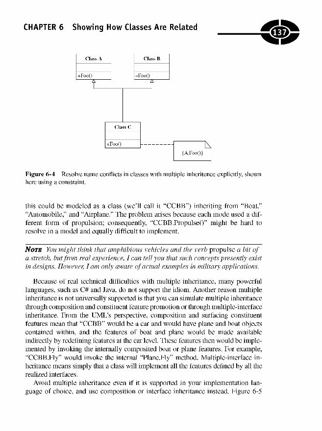
CHAPTER 6 Showing How Classes Are Related
Figure 6-4 Resolve name conflicts in classes with multiple inheritence explicitly, shownhere using a constraint.
this could be modeled as a class (we'll call it "CCBB") inheriting from "Boat,""Automobile," and "Airplane." The problem arises because each mode used a dif-ferent form of propulsion; consequently, "CCBB.PropulseO" might be hard toresolve in a model and equally difficult to implement.
NOTE You might think that amphibious vehicles and the verb propulse a bit ofa stretch, but from real experience, I can tell you that such concepts presently existin designs. However, I am only aware of actual examples in military applications.
Because of real technical difficulties with multiple inheritance, many powerfullanguages, such as C# and Java, do not support the idiom. Another reason multipleinheritance is not universally supported is that you can simulate multiple inheritancethrough composition and constituent feature promotion or through multiple-interfaceinheritance. From the UML's perspective, composition and surfacing constituentfeatures mean that "CCBB" would be a car and would have plane and boat objectscontained within, and the features of boat and plane would be made availableindirectly by redefining features at the car level. These features then would be imple-mented by invoking the internally composited boat or plane features. For example,"CCBB.Fly" would invoke the internal "Plane.Fly" method. Multiple-interface in-heritance means simply that a class will implement all the features defined by all therealized interfaces.
Avoid multiple inheritance even if it is supported in your implementation lan-guage of choice, and use composition or interface inheritance instead. Figure 6-5
.137.
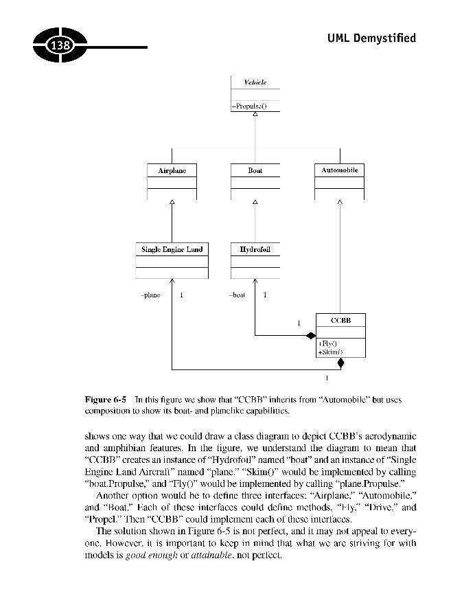
UML Demystified
Figure 6-5 In this figure we show that "CCBB" inherits from "Automobile" but usescomposition to show its boat- and planelike capabilities.
shows one way that we could draw a class diagram to depict CCBB's aerodynamicand amphibian features. In the figure, we understand the diagram to mean that"CCBB" creates an instance of "Hydrofoil" named "boat" and an instance of "SingleEngine Land Aircraft" named "plane." "Skim()" would be implemented by calling"boatPropulse," and "FlyO" would be implemented by calling "plane.Propulse."
Another option would be to define three interfaces: "Airplane," "Automobile,"and "Boat." Each of these interfaces could define methods, "Fly," "Drive," and"Propel." Then "CCBB" could implement each of these interfaces.
The solution shown in Figure 6-5 is not perfect, and it may not appeal to every-one. However, it is important to keep in mind that what we are striving for withmodels is good enough or attainable, not perfect.
138
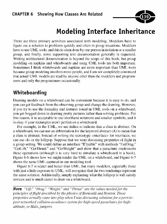
CHAPTER 6 Showing How Classes Are Related
Modeling Interface InheritanceThere are three primary activities associated with modeling. Modelers have tofigure out a solution to problems quickly and often in group situations. Modelershave to use UML tools, and this is often done by one person in isolation or a smallergroup, and finally, some supporting text documentation generally is requested.Writing architectural documentation is beyond the scope of this book, but groupmodeling on napkins and whiteboards and using UML tools are both important.Sometimes I think whiteboards and napkins are more important than UML toolsbecause group modeling involves more people, and I am not completely convincedthat actual UML models are read by anyone other than the modelers and program-mers and only the programmers occasionally.
Whiteboarding
Drawing models on a whiteboard can be convenient because it is easy to do, andyou can get feedback from the observing group and change the drawing. However,if you try to use the formality and features found in UML tools on a whiteboard,you get bogged down in drawing pretty pictures rather than solving problems. Forthis reason, it is acceptable to use shorthand notations and smaller symbols, and itis okay if your rectangles aren't perfect on a whiteboard.
For example, in the UML, we use italics to indicate that a class is abstract. Ona whiteboard, we can use an abbreviation for the keyword abstract (A) to mean thata class is abstract. Instead of writing the stereotype «interface» for interfaces, wecan use «I» or the lollipop. Suppose that we were discussing properties of flight ina group setting. We could define an interface "IFlyable" with methods "GetDrag,""GetLift," "GetThrust," and "GetWeight" and show that a parachute implementsthese operations (although it is very hard to simulate a whiteboard in a book).Figure 6-6 shows how we might render the UML on a whiteboard, and Figure 6-7shows the same UML captured in our modeling tool.
Figure 6-7 is neater and better than UML, but many modelers, especially thosewith just a little exposure to UML, will recognize that the two renderings representthe same solution. Additionally, simply explaining what the lollipop is will satisfynovices and is much easier to draw on a whiteboard.
NOTE "Lift," "Drag," "Weight," and "Thrust" are the values needed for theprinciples of flight described by the physics of Bernoulli and Newton. Theseproperties actually came into play when I was discussing solutions for a peer-to-peer networked collision-avoidance system for high-speed parachutes for high-altitude, or Halo, jumpers.
139.
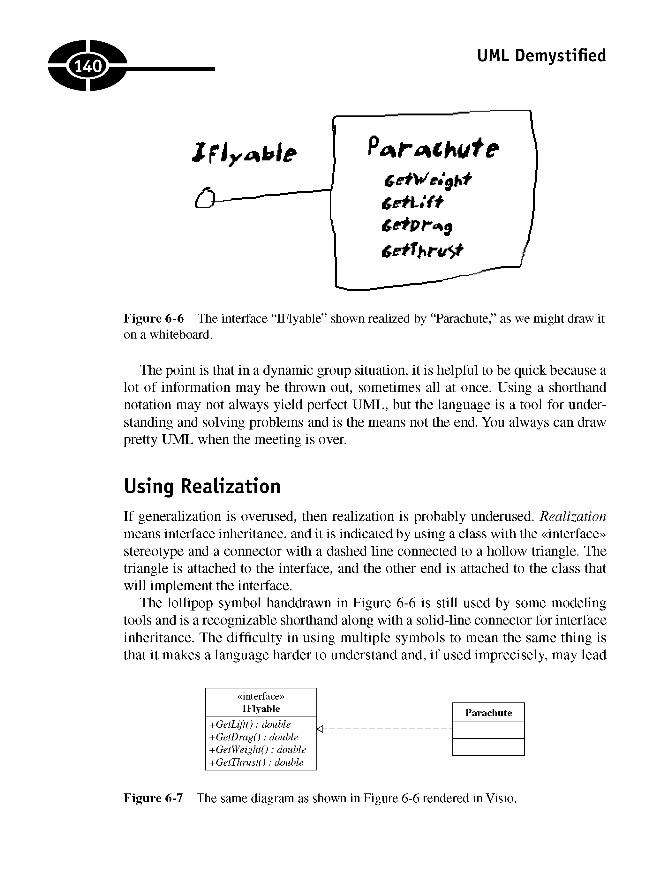
UML Demystified
Figure 6-6 The interface "IFlyable" shown realized by "Parachute," as we might draw iton a whiteboard.
The point is that in a dynamic group situation, it is helpful to be quick because alot of information may be thrown out, sometimes all at once. Using a shorthandnotation may not always yield perfect UML, but the language is a tool for under-standing and solving problems and is the means not the end. You always can drawpretty UML when the meeting is over.
Using Realization
If generalization is overused, then realization is probably underused. Realizationmeans interface inheritance, and it is indicated by using a class with the «interface»stereotype and a connector with a dashed line connected to a hollow triangle. Thetriangle is attached to the interface, and the other end is attached to the class thatwill implement the interface.
The lollipop symbol handdrawn in Figure 6-6 is still used by some modelingtools and is a recognizable shorthand along with a solid-line connector for interfaceinheritance. The difficulty in using multiple symbols to mean the same thing isthat it makes a language harder to understand and, if used imprecisely, may lead
Figure 6-7 The same diagram as shown in Figure 6-6 rendered in Visio.
.140
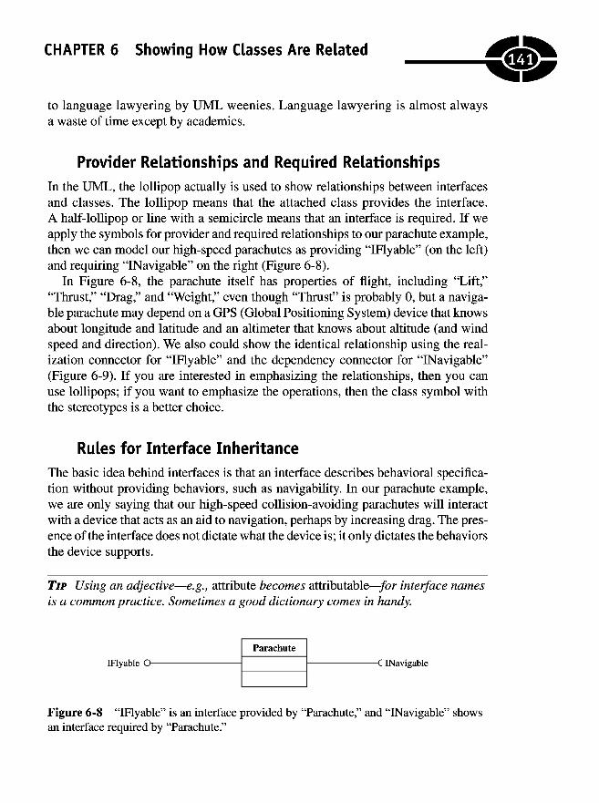
CHAPTER 6 Showing How Classes Are Related
to language lawyering by UML weenies. Language lawyering is almost alwaysa waste of time except by academics.
Provider Relationships and Required Relationships
In the UML, the lollipop actually is used to show relationships between interfacesand classes. The lollipop means that the attached class provides the interface.A half-lollipop or line with a semicircle means that an interface is required. If weapply the symbols for provider and required relationships to our parachute example,then we can model our high-speed parachutes as providing "IFlyable" (on the left)and requiring "INavigable" on the right (Figure 6-8).
In Figure 6-8, the parachute itself has properties of flight, including "Lift,""Thrust," "Drag," and "Weight," even though "Thrust" is probably 0, but a naviga-ble parachute may depend on a GPS (Global Positioning System) device that knowsabout longitude and latitude and an altimeter that knows about altitude (and windspeed and direction). We also could show the identical relationship using the real-ization connector for "IFlyable" and the dependency connector for "INavigable"(Figure 6-9). If you are interested in emphasizing the relationships, then you canuse lollipops; if you want to emphasize the operations, then the class symbol withthe stereotypes is a better choice.
Rules for Interface Inheritance
The basic idea behind interfaces is that an interface describes behavioral specifica-tion without providing behaviors, such as navigability. In our parachute example,we are only saying that our high-speed collision-avoiding parachutes will interactwith a device that acts as an aid to navigation, perhaps by increasing drag. The pres-ence of the interface does not dictate what the device is; it only dictates the behaviorsthe device supports.
TIP Using an adjective—e.g., attribute becomes attributable—/or interface namesis a common practice. Sometimes a good dictionary comes in handy.
Figure 6-8 "IFlyable" is an interface provided by "Parachute," and "INavigable" showsan interface required by "Parachute."
141

UML Demystified
Figure 6-9 This figure depicts the same relationships as those described in Figure 6-8,specifically, that "Parachute" realizes "IFlyable" and depends on "INavigable."
Interfaces do not provide behaviors; they only stipulate what they must be. Therule is that an interface must be implemented through realization or inheritance.This means that
• Given interface A, class B can implement all the behaviors described byinterface A.
• Given interface A and interface B, which inherits from interface A, class Ccan implement all the behaviors described by interfaces A and B.
• Given interface A and classes B and C, where class C inherits from classB or class B is composed of class C, together classes B and C implementall the behaviors described by interface A. In the composition scenario,B realizes A, and in the inheritance scenario, C realizes A.
Assuming that "INavigable's" behavioral specification included "GetLongi-tude()," "GetLatitudeO," and "GetAltitude()," then "INavigable" in the first scenariocould be realize by a device that can determine longitude, latitude, and altidude. Inthe second scenario, "INavigable" might inherit from an interface "lAltitudinal," andboth interfaces are realized by a single three-dimensionally orienting device. Finally,in the third scenario, "INavigable" might define all three-dimensional positions andbe implemented by generalization or composition, as shown in Figure 6-10. (Just tosatisfy my curiosity, such a device does exist—the Garmin eTrex Summit GPS withElectronic Compass and Altimeter. I want one.)
Again, it is worth noting that the three scenarios described all satisfy the require-ment of navigability adequately. The actual scenario I design depends on what classesI have available or what is convenient. If I already have part of the interface realizedby another class, then I might get the rest through inheritance of composition.Remember that the design doesn't have to be perfect, but the models should describewhat you mean adequately. You always can change your mind if you have to.
142

CHAPTER 6 Showing How Classes Are Related
Figure 6-10 Implementing an interface through inheritance.
Describing Aggregation and CompositionAggregation gets a mention here because it is the term most often used in object-oriented software design when talking about composition, i.e., when talking aboutone class being composed of others. Aggregation is the term used, but compositionis what is meant. As I said earlier, the aggregation connector—composed of a hol-low diamond and a solid line—has an ambiguous meaning that is no different froman association, and association is preferred.
Composition uses a solid diamond and a solid line. When you use composition,it means that the class that represents the whole, or composite class, contains theone and only instance of the class representing the part; it also means that the wholeclass is responsible for the lifetime of the part class.
Composition means that the composite class must ensure that all its parts arecreated and attached to the composite before the composite is wholly constructed.As long as the composite exists, it can be implemented to rely on none of its partsbeing destroyed by any other entity. When the composite is destroyed, it mustdestroy the parts, or it can explicitly remove parts and hand them off to some otherobject. The multiplicity of the composite is always 1 or 0.1.
To demonstrate composition, we can modify the relationship illustrated inFigure 6-10. In this figure I demonstrated how to satisfy an interface through inheri-tance, but the name of the child class, "GPSWithAltimeter," sounds like a compositionrelationship. The word with suggests composition to me more than it suggests in-heritance. In order to satisfy the interface, we can define "GPSWithAlitimeter" as thecomposite, define "Altimeter" as the part, and promote the "GetAltitude" method
143

UML Demystified
Figure 6-11 Figure 6-10 revised to use composition to add the behavior of the altimeter.
from "Altimeter." Figure 6-11 shows the revision, and the listing that follows showshow we might stub each of these elements in C#.
public interface INavigable
double GetLongitudedouble GetLatitude () ;double GetAltitudeO;
public class Altimeter
{/// <summary>
/// Return meters MSL (mean sea level)/// </summary>/// <returnsx/returns>public double GetAltitudeO
}}return 0;
public class GPSWithAltimeter : INavigable
private Altimeter altimeter;
public GPSWithAltimeter()
altimeter = new Altimeter();
}
144
{
{
{
{
{
}
():
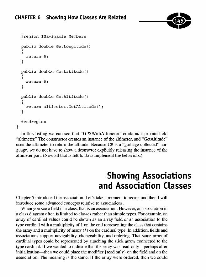
CHAPTER 6 Showing How Classes Are Related
#region INavigable Members
public double GetLongitude()
return 0;
public double GetLatitude()
return 0;
public double GetAltitude()
return altimeter.GetAltitude();
#endregion
In this listing we can see that "GPSWithAltimeter" contains a private field"altimeter." The constructor creates an instance of the altimeter, and "GetAltitude"uses the altimeter to return the altitude. Because C# is a "garbage collected" lan-guage, we do not have to show a destructor explicitly releasing the instance of thealtimeter part. (Now all that is left to do is implement the behaviors.)
m
Showing Associationsand Association Classes
Chapter 5 introduced the association. Let's take a moment to recap, and then I willintroduce some advanced concepts relative to associations.
When you see a field in a class, that is an association. However, an association ina class diagram often is limited to classes rather than simple types. For example, anarray of cardinal values could be shown as an array field or an association to thetype cardinal with a multiplicity of 1 on the end representing the class that containsthe array and a multiplicity of many (*) on the cardinal type. In addition, fields andassociations support navigability, changeability, and ordering. That same array ofcardinal types could be represented by attaching the stick arrow connected to thetype cardinal. If we wanted to indicate that the array was read-only—perhaps afterinitialization—then we could place the modifier {read only} on the field and on theassociation. The meaning is the same. If the array were ordered, then we could
{
{
{
}
}
}
}
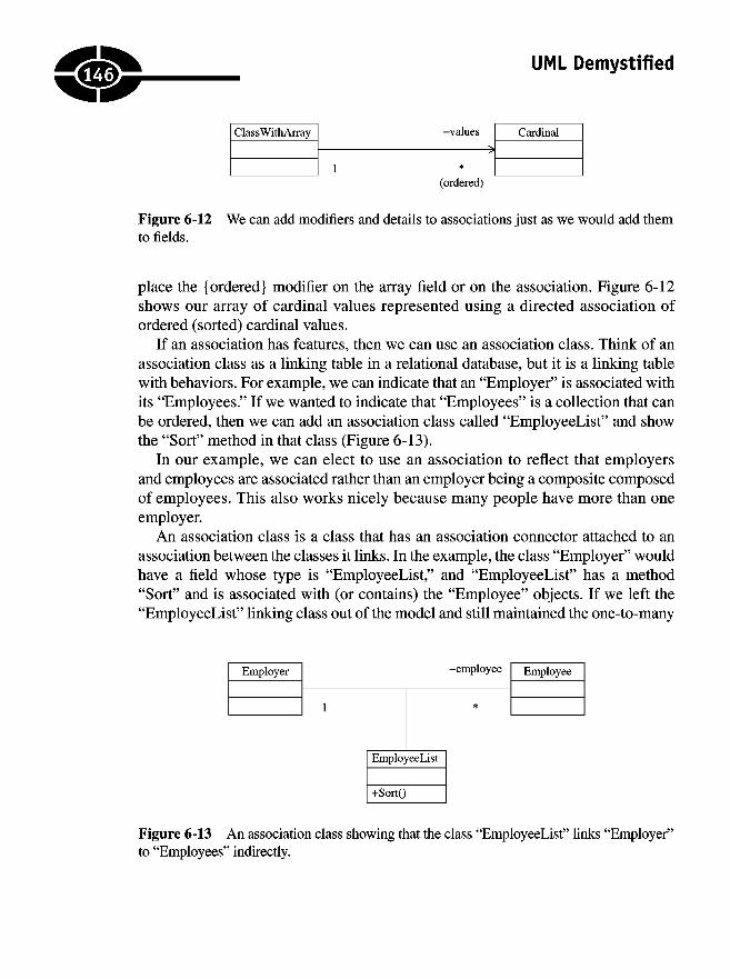
UML Demystified
Figure 6-12 We can add modifiers and details to associations just as we would add themto fields.
place the {ordered} modifier on the array field or on the association. Figure 6-12shows our array of cardinal values represented using a directed association ofordered (sorted) cardinal values.
If an association has features, then we can use an association class. Think of anassociation class as a linking table in a relational database, but it is a linking tablewith behaviors. For example, we can indicate that an "Employer" is associated withits "Employees." If we wanted to indicate that "Employees" is a collection that canbe ordered, then we can add an association class called "EmployeeList" and showthe "Sort" method in that class (Figure 6-13).
In our example, we can elect to use an association to reflect that employersand employees are associated rather than an employer being a composite composedof employees. This also works nicely because many people have more than oneemployer.
An association class is a class that has an association connector attached to anassociation between the classes it links. In the example, the class "Employer" wouldhave a field whose type is "EmployeeList," and "EmployeeList" has a method"Sort" and is associated with (or contains) the "Employee" objects. If we left the"EmployeeList" linking class out of the model and still maintained the one-to-many
Figure 6-13 An association class showing that the class "EmployeeList" links "Employer"to "Employees" indirectly.
146
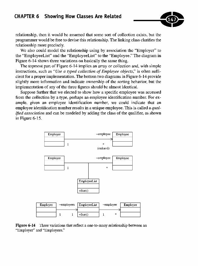
CHAPTER 6 Showing How Classes Are Related
relationship, then it would be assumed that some sort of collection exists, but theprogrammer would be free to devise this relationship. The linking class clarifies therelationship more precisely.
We also could model the relationship using by association the "Employer" tothe "EmployeeList" and the "EmployeeList" to the "Employee." The diagram inFigure 6-14 shows three variations on basically the same thing.
The topmost part of Figure 6-14 implies an array or collection and, with simpleinstructions, such as "Use a typed collection of Employee objects? is often suffi-cient for a proper implementation. The bottom two diagrams in Figure 6-14 provideslightly more information and indicate ownership of the sorting behavior, but theimplementation of any of the three figures should be almost identical.
Suppose further that we elected to show how a specific employee was accessedfrom the collection by a type, perhaps an employee identification number. For ex-ample, given an employee identification number, we could indicate that anemployee identification number results in a unique employee. This is called a qual-ified association and can be modeled by adding the class of the qualifier, as shownin Figure 6-15.
Figure 6-14 Three variations that reflect a one-to-many relationship between an"Employer" and "Employees."
147

UML Demystified
Figure 6-15 The qualifier that yields a unique employee is the "Employeeld.'
When you see a qualifier, you will expect to see the qualifier used as a parameterthat yields a specific instance of the associated type. The code listing that followsshows how we can implement this code in Visual Basic.NET using a typed collec-tion of "Employee" objects, a class named "Employeeld," and an indexer.
Imports System.Collections
Public Class EmployerPrivate employees As EmployeeList
Public Sub New( )employees = New EmployeeList
End Sub
End Class
Public Class EmployeeListInherits System.Collections.CollectionBase
Default Public Property Item(ByVal id As EmployeelD) As EmployeeGet
Return GetEmployee(id)End GetSet(ByVal Value As Employee)
SetEmployee(Value, id)End Set
End Property
Public Function Add(ByVal value As EmployeeList) As IntegerReturn List.Add(value)
End Function
Private Function Indexof(ByVal value As EmployeelD) As IntegerDim i As IntegerFor i = 1 To List.Count
If (CType(List(i), Employee).ID.IsEqual(value)) ThenReturn i
End IfNext
148
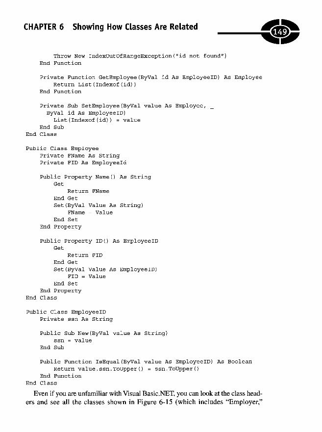
CHAPTER 6 Showing How Classes Are Relatedm
Throw New IndexOutOfRangeException ("id not found")End Function
Private Function GetEmployee(ByVal id As EmployeelD) As EmployeeReturn List(Indexof(id))
End Function
Private Sub SetEmployee(ByVal value As Employee, _ByVal id As EmployeelD)List(Indexof(id)) = value
End SubEnd Class
Public Class EmployeePrivate FName As StringPrivate FID As Employeeld
Public Property NameO As StringGet
Return FNameEnd GetSet(ByVal Value As String)
FName = ValueEnd Set
End Property
Public Property ID() As EmployeelDGet
Return FIDEnd GetSet(ByVal Value As EmployeelD)
FID = ValueEnd Set
End PropertyEnd Class
Public Class EmployeelDPrivate ssn As String
Public Sub New(ByVal value As String)ssn = value
End Sub
Public Function IsEqual(ByVal value As EmployeelD) As BooleanReturn value.ssn.ToUpper() = ssn.ToUpper()
End FunctionEnd Class
Even if you are unfamiliar with Visual Basic.NET, you can look at the class head-ers and see all the classes shown in Figure 6-15 (which includes "Employer,"
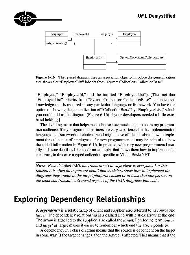
UML Demystified
Figure 6-16 The revised diagram uses an association class to introduce the generalizationthat shows that "EmployeeList" inherits from "System.Collections.CollectionBase."
"Employee," "Employeeld," and the implied "EmployeeList"). [The fact that"EmployeeList" inherits from "System.Collections.CollectionBase" is specializedknowledge that is required in any particular language or framework. You have theoption of showing the generalization of "Collections ase" by "EmployeeList," whichyou could add to the diagram (Figure 6-16) if your developers needed a little extrahand holding.]
The deciding factor that helps me to choose how much detail to add is my program-mer audience. If my programmer partners are very experienced in the implementationlanguage and framework of choice, then I might leave off details about how to imple-ment the collection of employees. For new programmers, it may be helpful to showthe added information in Figure 6-16. In practice, with very new programmers I usu-ally add more detail and then code an exemplar that shows them how to implement theconstruct, in this case a typed collection specific to Visual Basic.NET.
NOTE Even detailed UML diagrams aren 't always clear to everyone. For thisreason, it is often an important detail that modelers know how to implement thediagrams they create in the target platform chosen or at least that one person onthe team can translate advanced aspects of the UML diagrams into code.
Exploring Dependency RelationshipsA dependency is a relationship of client and supplier also referred to as source andtarget. The dependency relationship is a dashed line with a stick arrow at the end.The arrow is attached to the supplier, also called the target. I prefer the term source,and target as target makes it easier to remember which end the arrow points to.
A dependency in a class diagram means that the source is dependent on the targetin some way. If the target changes, then the source is affected. This means that if the
150

CHAPTER 6 Showing How Classes Are Related
target's interface changes, then implementation of the source will be affected.Dependencies are not transitive. For instance, if class A is dependent on class B andclass B is dependent on class C, then if class C's interface changes, class B's imple-mentation may have to change but not necessarily class B's interface. However, ifdependencies are cyclic—class A depends on class B depends on class C dependson class A—then changes to class C can have a cyclic effect that makes changesvery difficult, resulting in a brittle implementation. As a general rule, avoid compli-cated and cyclic dependencies.
Directed associations, composition, and inheritance imply a dependency. If class Ahas a directed association with class B, then class A is dependent on class B. If classB inherits from class A, then class B is dependent on class A. Association andgeneralization are more precise relationships with their own connotations; usedependency when one of the more specific kinds of relationships doesn't apply.
Finally, before we explore some of the predefined stereotypes that apply to depen-dencies, don't try to show all dependency relationships. Just draw the dependenciesthat are important.
Table 6-1 shows the predefined stereotypes for dependencies. Often the implica-tion of a dependency is clear by its context, but these stereotypes exist to clearly
access
bind
call
create
derive
instantiate
permit
realize
refine
send
substitute
trace
use
Private reference to another package's contents.
Describes a new element that is created when the templateparameter is assigned.
A method in the source calls a method in the target.
The source creates an instance of the target.
One object is derived from another.
The source creates an instance of the target.
The source can access the target's private members (e.g.,implemented as a friend relationship in some languages).
The source implements the interface of the target. (The realizationconnector is a better choice.)
The source refines the target. This is used for traceability betweenmodels (e.g., between an analysis and design model).
Indicates a sender and receiver of a signal.
The source can be substituted for the target. (This is similar to howa subclass can be substituted for its superclass.)
Used to link model elements.
The source needs the target to complete its implementation.
Table 6-1 A List of Stereotypes for Dependency Relationships Defined by the UMLVersion 2.0
151
UML Demystified
state your intended use. (Following the table is a brief description of each of thedependency relationships.)
Often it is enough to draw the occasional dependency connector in code andimplement what you mean. The following paragraphs elaborate on some of thedependency relationships described in Table 6-1.
The "access" dependency supports importing packages privately. Some of theseconcepts are new in UML version 2.0, and this is one I haven't had occasion to use.The closest example that might apply here is the difference between the interfaceand implementation use clauses in Delphi. Essentially, Delphi supports privateimportation in its implementation use clauses.
If you have ever read The C++ Programming Language, by Bjarne Stroustrop,then you would have read the discourse on template classes. In C with classes, tem-plates originated as a weakly typed construct devised by using substitution andmacros. The result was that the new name created by concatenating the string typeresulted in a new class. With templates, the result is the same. When you define theparameter for parameterized types—templates or generics—you have a new entity."Bind" exists for purposes of modeling this occurrence.
"Call" straightforwardly calls a method of the target class. "Create" indicatesthat the source creates an instance of the target. You might see this relationship inconjunction with the factory pattern. A factory's sole purpose is to perform all thesteps necessary to create the correct object.
"Derive," "realize," "refine," and "trace" are abstract dependencies. They exist torepresent two versions of the same thing. For example, the "realize" dependencyimplies the same relationship as a realization—i.e., the implementation of an inter-face. "Trace" is used to connect model elements as they evolve, e.g., use cases touse case realizations.
"Instantiate" also might be used to indicate that the source creates instances ofthe target. A better example has to do with runtime type information or reflection in.NET. We could show that a metaclass (or the an instance of the "Type" object in.NET) is used to create an instance of a class.
The "permit" stereotype is used to indicate that the source can invoke nonpublicmembers of the target. This relationship is supported by the "Friend" modifier inlanguages such as Visual Basic and through dynamic reflection.
A signal is like an event that occurs out of sequence. For example, when you areasleep and your alarm begins to ring, this is a signal to wake up. The "signal" stereotypeis used to indicate that something has happened that needs a response. Think event.
The "substitute" stereotype applies when the source can be substituted with thetarget. The clearest form of substitution is a child class in place of a parent.Finally, the "use" stereotype is common. "Use" simply implies that the source needsthe target to be complete. "Use" is a more generalized form of "call," "create,""instantiate," and "send."
152

CHAPTER 6 Showing How Classes Are Related
Adding Details to ClassesThe devil is in the details, as they say. Class diagrams can include a lot of informa-tion that is conveyed by text characters, fonts, and what is included, as well as whatis excluded. I prefer to be explicit to the extent possible but not verbose and to bepersonally present to resolve ambiguities during implementation. In this section Iwant to point out a few details that you can look for and some respectable shortcutsyou can take to ensure that you understand UML diagrams created by others andthat others understand your diagrams. Because these basic guidelines are relativelyshort, they are listed as statements.
• Underlined features indicate static features.
• Derived properties are demarked by a slash preceding the property name.For example, given properties "hours worked" and "hourly wage," we canderive the wage, which would appear as "/wage."
• Italicized class names indicate abstract classes. An abstract class has someelements with no implementation and depends on subclasses for a completeimplementation.
• Model fields; properties are implied in languages that support properties. Inlanguages that don't support properties, methods prefixed with "get_" and"set_" yield the same result.
• Constraints specify before (pre) and after (post) conditions. Use constraintsto indicate the state in which an object should be when a method is enteredand a method is exited. The "assertion" construct supports this style ofprogramming.
• When you are modeling operations, try to maintain a minimum numberof public operations, use private fields, and permit access to fields throughproperties (if supported) or accessor methods (if properties are not supported).
Quiz1. A subclass has access to a superclass's private members.
a. True
b. False
153

UML Demystified
2. If a child class has more than one parent and each parent introduces anoperation with the same name,
a. the programmer should resolve the name conflict explicitly.
b. all languages that support multiple inheritance resolve conflictsimplicitly.
c. Neither of the above. Conflicts are not allowed.
3. Which of the following statements is (are) true?
a. Generalization refers to subtypes.
b. Classification refers to subtypes.
c. Generalization refers to object instances.
d. Classification refers to object instances.
e. None of the above
4. To realize
a. means to inherit from a parent class.
b. means to implement an interface.
c. means to promote the constituent members in a composite class.
d. is a synonym for aggregation.
5. If a language does not support multiple inheritance, then the result can beapproximated by
a. an association and the promotion of constituent properties.
b. realization.
c. composition and the promotion of constituent properties.
d. aggregation and the promotion of constituent properties.
6. Dynamic classification—where an object is changed at runtime—can bemodeled using
a. generalization.
b. association.
c. realization.
d. composition.
7. An "association" class is referred to as a linking class.
a. True
b. False
154J
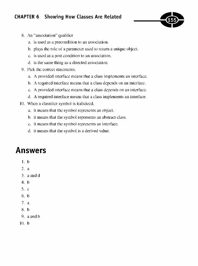
CHAPTER 6 Showing How Classes Are Related
8. An "association" qualifier
a. is used as a precondition to an association.
b. plays the role of a parameter used to return a unique object.
c. is used as a post condition to an association.
d. is the same thing as a directed association.
9. Pick the correct statements.
a. A provided interface means that a class implements an interface.
b. A required interface means that a class depends on an interface.
c. A provided interface means that a class depends on an interface.
d. A required interface means that a class implements an interface.
10. When a classifier symbol is italicized,
a. it means that the symbol represents an object.
b. it means that the symbol represents an abstract class.
c. it means that the symbol represents an interface.
d. it means that the symbol is a derived value.
Answers1. b
2. a
3. a and d
4. b
5. c
6. b
7. a
8. b
9. a and b
10. b
Era

This page intentionally left blank

CHAPTER
Using StateChart Diagrams
Historically, the difference between state charts and activity diagrams was muddled.In the Unified Modeling Language (UML) version 2.0, state charts come into theirown as a distinct and separate diagram.
State charts (also known as state machines) are good at showing an object's stateover many use cases and good at defining protocols that describe a correct orchestra-tion of messages, such as might be needed for database access or TransmissionControl Protocol (TCP) connectivity. State charts are ideally suited for describingthe behavior of user interfaces and device controllers for real-time systems. Whereasinteraction diagrams are good at understanding systems, state charts are good at in-dicating behavior precisely. If you are working in real-time systems or with physicaldevice controllers, then you may use state charts frequently. However, a huge num-ber of applications are business applications based on graphical user interfaces(and databases and many programmers use modern rapid application developmenttools to prototype interfaces rather than define their behaviors using state charts).
157
7
Copyright © 2005 by The McGraw-Hill Companies. Click here for terms of use.
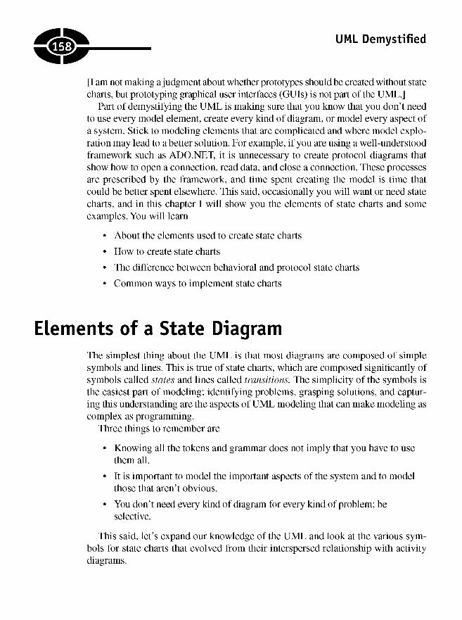
UML Demystified
[I am not making a judgment about whether prototypes should be created without statecharts, but prototyping graphical user interfaces (GUIs) is not part of the UML.]
Part of demystifying the UML is making sure that you know that you don't needto use every model element, create every kind of diagram, or model every aspect ofa system. Stick to modeling elements that are complicated and where model explo-ration may lead to a better solution. For example, if you are using a well-understoodframework such as ADO.NET, it is unnecessary to create protocol diagrams thatshow how to open a connection, read data, and close a connection. These processesare prescribed by the framework, and time spent creating the model is time thatcould be better spent elsewhere. This said, occasionally you will want or need statecharts, and in this chapter I will show you the elements of state charts and someexamples. You will learn
• About the elements used to create state charts
• How to create state charts
• The difference between behavioral and protocol state charts
• Common ways to implement state charts
Elements of a State DiagramThe simplest thing about the UML is that most diagrams are composed of simplesymbols and lines. This is true of state charts, which are composed significantly ofsymbols called states and lines called transitions. The simplicity of the symbols isthe easiest part of modeling; identifying problems, grasping solutions, and captur-ing this understanding are the aspects of UML modeling that can make modeling ascomplex as programming.
Three things to remember are
• Knowing all the tokens and grammar does not imply that you have to usethem all.
• It is important to model the important aspects of the system and to modelthose that aren't obvious.
• You don't need every kind of diagram for every kind of problem; beselective.
This said, let's expand our knowledge of the UML and look at the various sym-bols for state charts that evolved from their interspersed relationship with activitydiagrams.
158

CHAPTER 7 Using State Chart Diagrams
Exploring State Symbols
There are several state symbols. The most common is the rounded rectangle, orsimple state. Significantly state charts consist of simple states and transitions, butthere are other states that play important though less prominent roles.
In this section I will explain simple states with regular and do activities; orthogo-nal and nonorthogonal composite states; initial, terminate, and final states; junctions,choices, and history states; submachine states; and superstates, exit, and entrypoints.
Using Initial, Final, and Terminate States
Recall that state charts and activity diagrams have a shared history. Consequently,although their definitions in the UML version 2.0 are more clearly delineated, statecharts and activity diagrams still share some symbols in common. Three states,initial, final, and terminal, use the same symbols found in activity diagrams but playroles tailored to state charts.
The initial state is a solid circle representing a pseduostate in protocol statemachines—see "Creating Protocol State Machines" below—in the UML version 2.0.You can use the initial state in state charts in general, but it is not used commonly.The final state uses the same symbol—a solid circle with a circular outline—as thefinal activity in activity diagrams and is used to indicate the end of a state chart—see "Creating Behavioral State Machines" below. Final states don't have outgoingtransitions; don't have entry, exit, or do activities; don't reference submachines; andaren't divided into regions. (These concepts are described in a moment.) The finalstate is an endpoint without elaboration. The terminate state is an X used in protocolstate machines; think of it as a dead end.
Using Junction and Choice States
A choice state is a pseudostate that is used in protocol state machines. A choicelooks like a decision diamond and plays a similar role to a decision in activity dia-grams. A choice has a single incoming transition and has more than one outgoingtransition. Outgoing transitions are taken depending on which guard condition eval-uates to true. If more than one guard evaluates to true, then an arbitrary transition istaken, but at least one guard must evaluate to true (Figure 7-1).
A junction is a solid circle, like the initial state, and is used to merge several in-coming transitions into a single outgoing transition or split a single incoming transitioninto multiple outgoing transitions (Figure 7-2).
EljCtJ
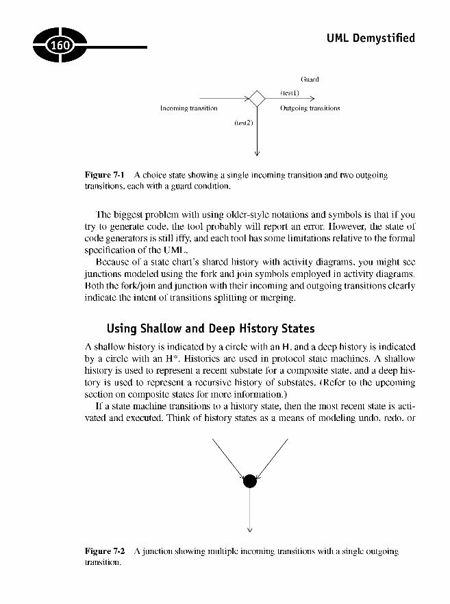
UML Demystified
Figure 7-1 A choice state showing a single incoming transition and two outgoingtransitions, each with a guard condition.
The biggest problem with using older-style notations and symbols is that if youtry to generate code, the tool probably will report an error. However, the state ofcode generators is still iffy, and each tool has some limitations relative to the formalspecification of the UML.
Because of a state chart's shared history with activity diagrams, you might seejunctions modeled using the fork and join symbols employed in activity diagrams.Both the fork/join and junction with their incoming and outgoing transitions clearlyindicate the intent of transitions splitting or merging.
Using Shallow and Deep History States
A shallow history is indicated by a circle with an H, and a deep history is indicatedby a circle with an H*. Histories are used in protocol state machines. A shallowhistory is used to represent a recent substate for a composite state, and a deep his-tory is used to represent a recursive history of substates. (Refer to the upcomingsection on composite states for more information.)
If a state machine transitions to a history state, then the most recent state is acti-vated and executed. Think of history states as a means of modeling undo, redo, or
Figure 7-2 A junction showing multiple incoming transitions with a single outgoingtransition.
160
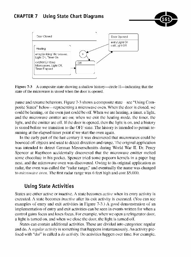
CHAPTER 7 Using State Chart Diagrams
Figure 7-3 A composite state showing a shallow history-state of the microwave is stored when the door is opened.
-circle H—indicating that the
pause and resume behaviors. Figure 7-3 shows a composite state—see "Using Com-posite States" below—representing a microwave oven. When the door is closed, wecould be heating, or the oven just could be off. When we are heating, a timer, a light,and the microwave emitter are on; when we exit the heating mode, the timer, thelight, and the emitter are off. If the door is opened, then the light is on, and a historyis stored before we transition to the OFF state. The history is intended to permit re-suming at the elapsed timer point if we start the oven again.
In the early part of the last century it was discovered that microwaves could bebounced off objects and used to detect direction and range. The original applicationwas intended to detect German Messerschmitts during World War II. Dr. PercySpencer at Raytheon accidentally discovered that the microwave emitter meltedsome chocolate in his pocket. Spencer tried some popcorn kernels in a paper bagnext, and the microwave oven was discovered. Owing to its original application asradar, the oven was called the "radar range," and eventually the name was changedto microwave oven. The first radar range was 6 feet high and cost $5,000.
Using State Activities
States are either active or inactive. A state becomes active when its entry activity isexecuted. A state becomes inactive after its exit activity is executed. (You can seeexamples of entry and exit activities in Figure 7-3.) A good demonstration of animplementation of entry and exit activities can be seen in events written for when acontrol gains focus and loses focus. For example, when we open a refrigerator door,a light is turned on, and when we close the door, the light is turned off.
States can contain additional activities. These are divided into categories: regularand do. A regular activity is something that happens instantaneously. An activity pre-fixed with "do/" is called a do activity. Do activities happen over time. For example,
161
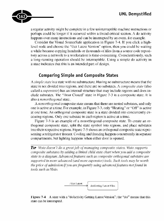
UML Demystified
a regular activity might be complete in a few uninterruptible machine instructions orperhaps could be longer if it occurred within a thread critical section. A do activityhappens over many instructions and can be interrupted by an event, for example.
Consider the Visual SourceSafe application in Figure 7-4. If you click a high-level node and choose the "Get Latest Version" option, then you could be waitinga while because copying hundreds or thousands of files from a source code reposi-tory across a network to a workstation is time-consuming. Conscientiously, sucha long-running operation should be interruptible. Using a simple do activity ina state indicates that this is an intended part of design.
Comparing Simple and Composite States
A simple state is a state with no substructure. Having no substructure means that thestate is not divided into regions, and there are no substates. A composite state (alsocalled a superstate) has an internal structure that may include regions and does in-clude substates. The "Door Closed" state in Figure 7-3 is a composite state. It isalso a nonorthogonal state.
A nonorthogonal composite state means that there are nested substates, and onlyone is active at a time. For example, in Figure 7-3, only "Heating" or "Off" is activeat one time. An orthogonal composite state is a state divided into concurrently ex-ecuting regions. Only one substate in each region is active at a time.
Figure 7-3 is an example of a nonorthogonal composite state. To create an or-thogonal composite state, split the state symbol into regions, and place substatesinto their respective regions. Figure 7-5 shows an orthogonal composite state repre-senting a refrigerator freezer. Cooling and freezing happen concurrently in separatecompartments, but lighting happens when either door is opened.
TIP Visio doesn't do a great job of managing composite states. Visio supportscomposite substates by adding a linked child state chart when you add a compositestate to a diagram. Advanced features such as composite orthogonal substates aresupported in more advanced (and more expensive) tools. Such tools may be worththe price of admission if you are frequently using advanced features not found intools such as Visio.
Figure 7-4 A state with a "do/activity Getting Latest Version"; the "do/" means that thisstate can be interrupted.
162

CHAPTER 7 Using State Chart Diagrams
Figure 7-5 A composite orthogonal state that represents simultaneous cooling and freezing.
Figure 7-3 was laboriously created using MS-Paint, whereas Figure 7-5 was cre-ated much more quickly using Rational XDE. I do a lot of modeling, so it is worththe price of admission to use Rational XDE, but on some projects, I have usedVisio, and it works fine for day-to-day modeling. Good tools are the mark of a goodcraftsperson, but spending a lot of money is no guarantee of success.
Using Internal Activities
Internal activities are like self-transitions—refer to "Exploring Transitions" below.An internal activity is a response that happens internally and triggers an activitywithout executing an exit and entry activity. Internal activities use the same event,guard, and activity notation that is used on transitions. I'll talk more about transi-tions shortly.
Linking to Submachines
Instead of repeating state chart (state machine) diagrams, you want to reuse dia-grams. This applies to state machines. The UML supports modeling submachinesby naming the substate machine after the state name, separated by a class name.(This looks like the C++ variable-class name declaration statement.) For example,
mystate : MyStateMachine
indicates that "MyState" is an instance of the state machine named "MyState-Machine."
If you are using Visio, then you can use the name, colon, state machine notationto reference a substate machine. Other tools—such as Rational XDE, mentionedpreviously—support a special symbol for submachines and will link the referencedsubmachine dynamically.
.163.
UML Demystified
Exploring Transitions
Transitions are directed lines that connect states. Transitions occur based on sometriggering mechanism—commonly implemented as events—and may or may notproceed based on a guard condition, resulting in some effect. This sort of cause-and-effect relationship illustrates why state machines can be useful for modelinguser interfaces. This section will explore triggering mechanisms, examples of guardconditions, and how to specify effects. I also will complete the discussion of inter-nal and external transitions introduced in the section "Using Internal Activities."
Specifying Triggers
A transition has a source state, a transition event, a guard, an effect, and a targetstate. Before the source state is exited, the exit activity occurs. When the transitiontrigger occurs, a guard condition can be tested to determine if the transition is taken.A taken transition results in an effect. Finally, the target's entry activity is executed.The directed line that represents the transition is labeled with the optional triggerevent, guard, and effect. If the activities in a state finish, then the result is calleda triggerless or completion transition.
Triggers, or events, that signify a transition are categorized as call, change, sig-nal, and timer events. A call event specifies a synchronous object call. A changeevent represents a change in the result of a Boolean expression. A signal event indi-cates an explicit, named synchronous message, and a timer event is a trigger thatoccurs after a specific interval of time. The trigger is the first element, if present,attached to a transition.
TIP Some tools may prefix specific kinds of transitions with labels such as "when"in the case ofVisio and change events.
Specifying Guard Conditions
Guard conditions are placed in brackets and must evaluate to a testable Booleancondition. (I have seen the notation for guard conditions on other diagrams, such asactivity and interaction diagrams.) If a guard condition is present, then it is evalu-ated and must result in a true value for the transition to complete.
Guard conditions should be relatively simple and should not result in side ef-fects. For example, "[x > 0]" is a good guard condition, but "increment x during theevaluation like [X++ > 0]" is a guard with side effects because the value of x ischanged each time the guard is executed.
.164
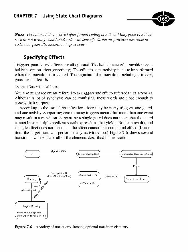
CHAPTER 7 Using State Chart Diagrams
NOTE Formal modeling evolved after formal coding practices. Many good practices,such as not writing conditional code with side effects, mirror practices desirable incode, and generally, models end up as code.
Specifying Effects
Triggers, guards, and effects are all optional. The last element of a transition sym-bol is the option effect (or activity). The effect is some activity that is to be performedwhen the transition is triggered. The signature of a transition, including a trigger,guard, and effect, is
Event [Guard] /Ef fec t
You also might see events referred to as triggers and effects referred to as activities.Although a lot of synonyms can be confusing, these words are close enough toconvey their purpose.
According to the formal specification, there may be many triggers, one guard,and one activity. Supporting zero to many triggers means that more than one eventmay result in a transition. Supporting a single guard does not mean that the guardcannot have multiple predicates (subexpressions that yield a Boolean result), anda single effect does not mean that the effect cannot be a compound effect. (In addi-tion, the target state can perform many activities too.) Figure 7-6 shows severaltransitions with some or all of the elements described in this section.
Figure 7-6 A variety of transitions showing optional transition elements.
165
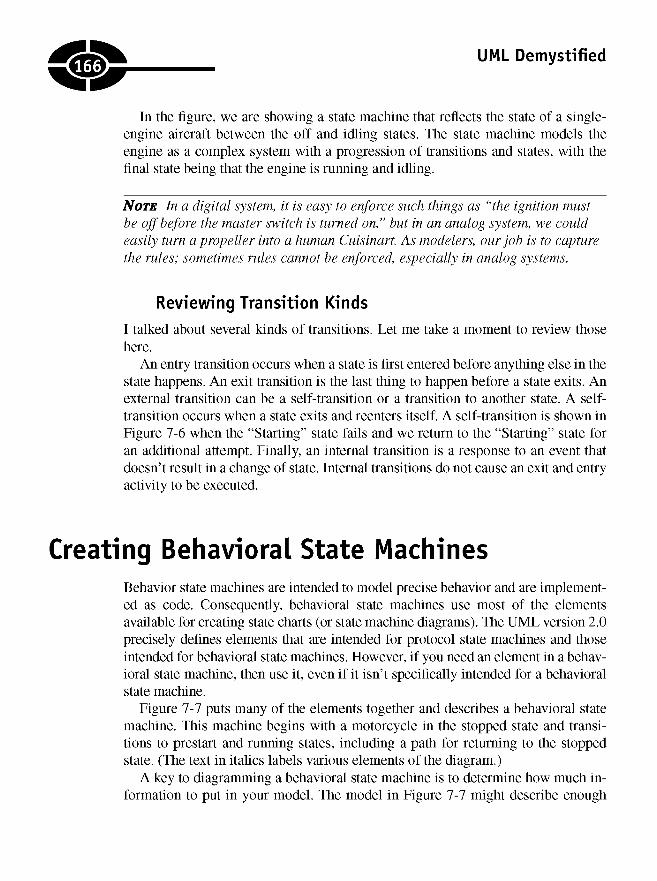
UML Demystified
In the figure, we are showing a state machine that reflects the state of a single-engine aircraft between the off and idling states. The state machine models theengine as a complex system with a progression of transitions and states, with thefinal state being that the engine is running and idling.
NOTE In a digital system, it is easy to enforce such things as "the ignition mustbe off before the master switch is turned on," but in an analog system, we couldeasily turn a propeller into a human Cuisinart. As modelers, our job is to capturethe rules; sometimes rules cannot be enforced, especially in analog systems.
Reviewing Transition Kinds
I talked about several kinds of transitions. Let me take a moment to review thosehere.
An entry transition occurs when a state is first entered before anything else in thestate happens. An exit transition is the last thing to happen before a state exits. Anexternal transition can be a self-transition or a transition to another state. A self-transition occurs when a state exits and reenters itself. A self-transition is shown inFigure 7-6 when the "Starting" state fails and we return to the "Starting" state foran additional attempt. Finally, an internal transition is a response to an event thatdoesn't result in a change of state. Internal transitions do not cause an exit and entryactivity to be executed.
Creating Behavioral State MachinesBehavior state machines are intended to model precise behavior and are implement-ed as code. Consequently, behavioral state machines use most of the elementsavailable for creating state charts (or state machine diagrams). The UML version 2.0precisely defines elements that are intended for protocol state machines and thoseintended for behavioral state machines. However, if you need an element in a behav-ioral state machine, then use it, even if it isn't specifically intended for a behavioralstate machine.
Figure 7-7 puts many of the elements together and describes a behavioral statemachine. This machine begins with a motorcycle in the stopped state and transi-tions to prestart and running states, including a path for returning to the stoppedstate. (The text in italics labels various elements of the diagram.)
A key to diagramming a behavioral state machine is to determine how much in-formation to put in your model. The model in Figure 7-7 might describe enough
166
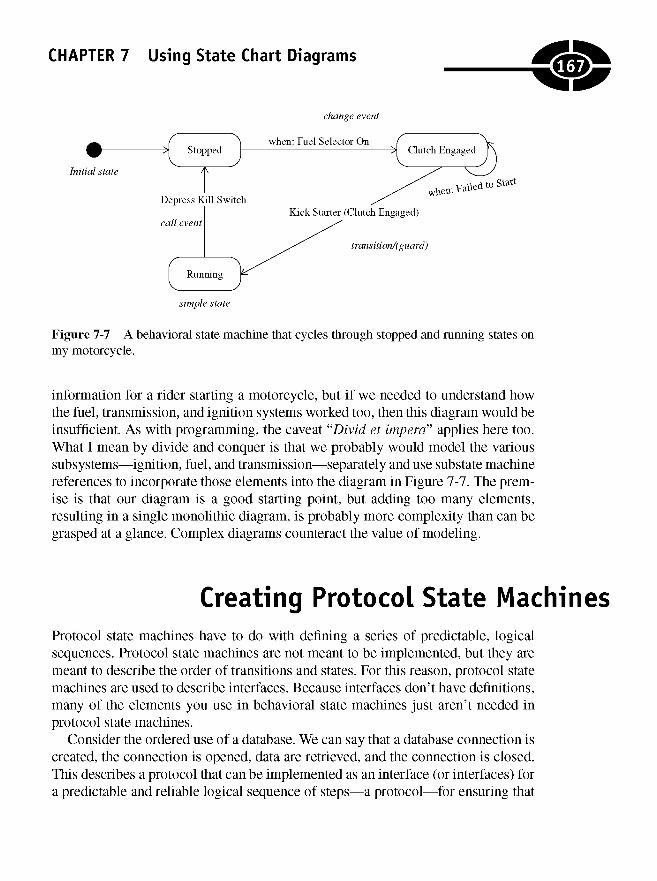
CHAPTER 7 Using State Chart Diagrams
Figure 7-7 A behavioral state machine that cycles through stopped and running states onmy motorcycle.
information for a rider starting a motorcycle, but if we needed to understand howthe fuel, transmission, and ignition systems worked too, then this diagram would beinsufficient. As with programming, the caveat "Divid et impera" applies here too.What I mean by divide and conquer is that we probably would model the varioussubsystems—ignition, fuel, and transmission—separately and use substate machinereferences to incorporate those elements into the diagram in Figure 7-7. The prem-ise is that our diagram is a good starting point, but adding too many elements,resulting in a single monolithic diagram, is probably more complexity than can begrasped at a glance. Complex diagrams counteract the value of modeling.
Creating Protocol State MachinesProtocol state machines have to do with defining a series of predictable, logicalsequences. Protocol state machines are not meant to be implemented, but they aremeant to describe the order of transitions and states. For this reason, protocol statemachines are used to describe interfaces. Because interfaces don't have definitions,many of the elements you use in behavioral state machines just aren't needed inprotocol state machines.
Consider the ordered use of a database. We can say that a database connection iscreated, the connection is opened, data are retrieved, and the connection is closed.This describes a protocol that can be implemented as an interface (or interfaces) fora predictable and reliable logical sequence of steps—a protocol—for ensuring that
167
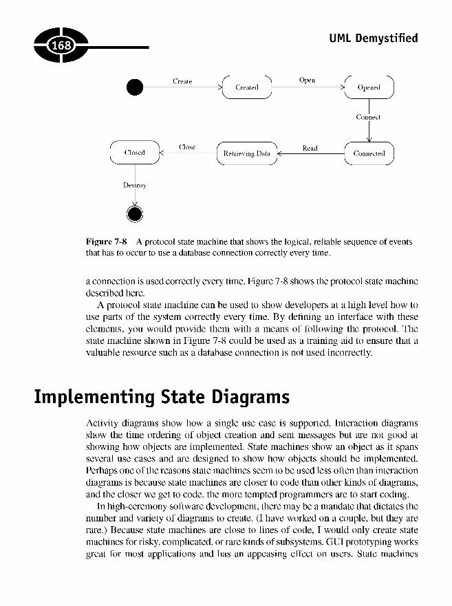
UML Demystified
Figure 7-8 A protocol state machine that shows the logical, reliable sequence of eventsthat has to occur to use a database connection correctly every time.
a connection is used correctly every time. Figure 7-8 shows the protocol state machinedescribed here.
A protocol state machine can be used to show developers at a high level how touse parts of the system correctly every time. By defining an interface with theseelements, you would provide them with a means of following the protocol. Thestate machine shown in Figure 7-8 could be used as a training aid to ensure that avaluable resource such as a database connection is not used incorrectly.
Implementing State DiagramsActivity diagrams show how a single use case is supported. Interaction diagramsshow the time ordering of object creation and sent messages but are not good atshowing how objects are implemented. State machines show an object as it spansseveral use cases and are designed to show how objects should be implemented.Perhaps one of the reasons state machines seem to be used less often than interactiondiagrams is because state machines are closer to code than other kinds of diagrams,and the closer we get to code, the more tempted programmers are to start coding.
In high-ceremony software development, there may be a mandate that dictates thenumber and variety of diagrams to create. (I have worked on a couple, but they arerare.) Because state machines are close to lines of code, I would only create statemachines for risky, complicated, or rare kinds of subsystems. GUI prototyping worksgreat for most applications and has an appeasing effect on users. State machines
168
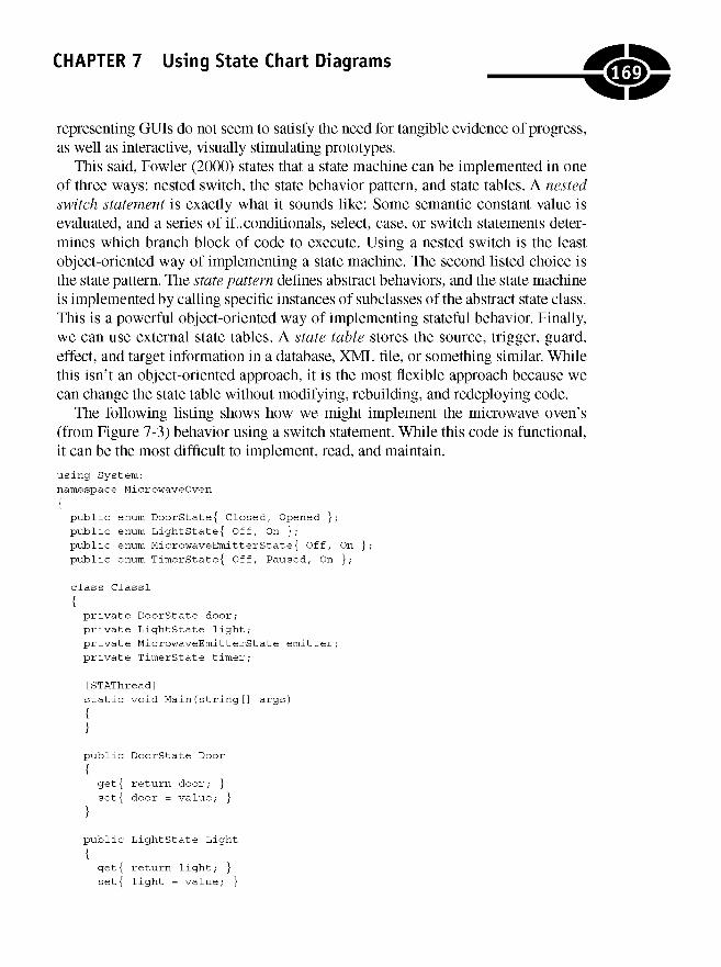
CHAPTER 7 Using State Chart Diagrams
representing GUIs do not seem to satisfy the need for tangible evidence of progress,as well as interactive, visually stimulating prototypes.
This said, Fowler (2000) states that a state machine can be implemented in oneof three ways: nested switch, the state behavior pattern, and state tables. A nestedswitch statement is exactly what it sounds like: Some semantic constant value isevaluated, and a series of if..conditionals, select, case, or switch statements deter-mines which branch block of code to execute. Using a nested switch is the leastobject-oriented way of implementing a state machine. The second listed choice isthe state pattern. The state pattern defines abstract behaviors, and the state machineis implemented by calling specific instances of subclasses of the abstract state class.This is a powerful object-oriented way of implementing stateful behavior. Finally,we can use external state tables. A state table stores the source, trigger, guard,effect, and target information in a database, XML file, or something similar. Whilethis isn't an object-oriented approach, it is the most flexible approach because wecan change the state table without modifying, rebuilding, and redeploying code.
The following listing shows how we might implement the microwave oven's(from Figure 7-3) behavior using a switch statement. While this code is functional,it can be the most difficult to implement, read, and maintain.using System;namespace MicrowaveOven
{public enum DoorState{ Closed, Opened };public enum LightState{ Off, On };public enum MicrowaveEmitterState{ Off, On };public enum TimerState{ Of f, Paused, On };
class Classl
{private DoorState door;private LightState light;private MicrowaveEmitterState emitter;private TimerState timer;
[STAThread]static void Main(string [] args)
{}public DoorState Door
{get{ return door; }set{ door = value; }
public LightState Light
{get{ return light; }set{ light = value; }
169
}
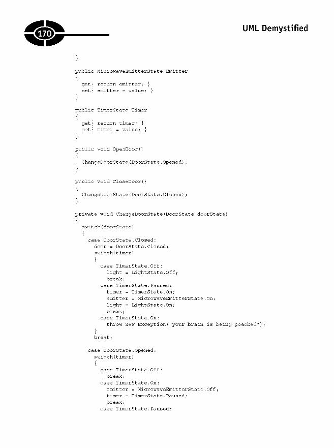
UML Demystified
}public MicrowaveEmitterState Emitter
{get{ return emitter; }set{ emitter = value; }
}public TimerState Timer
get{ return timer; }set{ timer = value; }
}public void OpenDoor()
ChangeDoorstate(DoorState.Opened);
}public void CloseDoor()
ChangeDoorstate(DoorState.Closed);
}private void ChangeDoorstate(DoorState doorState)
switch(doorState)
case DoorState.Closed:door = DoorState.Closed;switch(timer)
case TimerState.Off:light = LightState.Off;break;
case TimerState.Paused:timer = TimerState.On;emitter = MicrowaveEmitterState.On;light = LightState.On;break;
case TimerState.On:throw new Exception("your brain is being poached"),
break;
case DoorState.Opened:switch(timer)
{case TimerState.Off:break;
case TimerState.On:emitter = MicrowaveEmitterState.Off;timer = TimerState.Paused;break;
case TimerState.Paused:
.170.
}
{
{
{
{
{
{
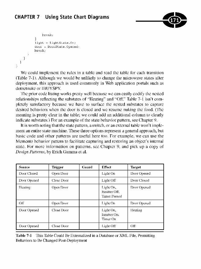
CHAPTER 7 Using State Chart Diagrams
break;
}light = LightState.On;door = DoorState.Opened;break;
We could implement the rules in a table and read the table for each transition(Table 7-1). Although we would be unlikely to change the microwave states afterdeployment, this approach is used commonly in Web application portals such asdotnetnuke or IBUYSPY.
The prior code listing works pretty well because we can easily codify the nestedrelationships reflecting the substates of "Heating" and "Off." Table 7-1 isn't com-pletely satisfactory because we have to surface the nested substates to capturedesired behaviors when the door is closed and we resume nuking the food. (Themeaning is pretty clear in the table; we could add an additional column to clearlyindicate substates.) For an example of the state behavior pattern, see Chapter 9.
It is worth noting that the state pattern, a switch, or an external table won't imple-ment an entire state machine. These three options represent a general approach, butbasic code and other patterns are useful here too. For example, we can use theMemento behavior pattern to facilitate capturing and restoring an object's internalstate. For more information on patterns, see Chapter 9, and pick up a copy ofDesign Patterns, by Erich Gamma et al.
Source
Door Closed
Door Opened
Heating
Off
Door Opened
Door Opened
Trigger
Open Door
Close Door
Open Door
Open Door
Close Door
Close Door
Guard Effect
Light On
Light Off
Light On,Emitter Off,Timer Paused
Light On
Light On,Emitter On,Timer On
Light Off
Target
Door Opened
Door Closed
Door Opened
Door Opened
Heating
Off
Table 7-1 This Table Could Be Externalized in a Database or XML File, PermittingBehaviors to Be Changed Post-Deployment
171
}}
}}
UML Demystified
Quiz1. State charts (or state machine diagrams) are good for
a. diagramming systems.
b. diagramming objects and messages for a single use case.
c. understanding a single use case.
d. specifying the behavior of an object across several use cases.
2. State machines are especially useful in exploring GUIs and real-timecontrollers.
a. True
b. False
3. A junction is used to
a. merge several incoming transitions to a single outgoing transition.
b. split a single incoming transition into several outgoing transitions.
c. Both a and b
d. None of the above
4. History pseudostates are used to restore previous states.
a. True
b. False
5. A regular activity executes
a. over time and a do activity executes immediately but can be interrupted.
b. immediately and a do activity executes over time and can be interrupted.
c. over time and can be interrupted and a do activity executes over time.
d. over time and a do activity executes overtime; only the do activity canbe interrupted.
6. Transitions are directed lines labeled with
a. an optional trigger event, a guard, and an effect.
b. a trigger event, an optional guard, and an effect.
c. a trigger event, a guard, and an optional effect.
d. optionally, a trigger event, a guard, and an effect.
172

CHAPTER 7 Using State Chart Diagrams
7. Internal transitions cause an enter and exit activity to be executed.
a. True
b. False
8. Self-transitions cause an enter and exit activity to be executed.
a. True
b. False
9. A composite orthogonal state
a. is divided into regions, and only one region can be active at a time.
b. is divided into regions, and only one substate can be active at a time.
c. is divided into regions, and only one substate per region can be activeat a time.
d. is composed of a single region, and multiple substates can be activesimultaneously.
10. A composite nonorthogonal state
a. is composed of regions, and only one region can be active at a time.
b. is not divided into regions, and only one substate can be active at a time.
c. is not divided into regions, and multiple substates can be active at a time.
d. is divided into regions, and one substate per region can be active at a time.
Answers1. d
2. a
3. c
4. a
5. b
6. a
7. b
8. a
9. c
10. b
173

This page intentionally left blank
CHAPTER
ModelingComponents
When I was 15,1 purchased my first car for $325. Go ahead and laugh—a $325 carin 1981 was as bad as you'd imagine it to be. Of course, being industrious, I beganto find ways to refurbish the car and make it as roadworthy as I knew how. One ofthe first things I realized about this 1974 Oldsmobile Cutlass rust bucket—besidesthat the front seat didn't lock, causing the seat to slide all the way forward whenI stopped and all the way back when I accelerated, the football-sized hole in theradiator, and four different sized tires—was that the serpentine belt needed replac-ing. I thought replacing a serpentine belt was a task I could handle.
After I got the car home, I settled on replacing the serpentine belt. I began toremove the radiator, water pump, and alternator. You get the picture. I realized thatthis was a bigger job than I might be able to do and resolved to take the car to the
8
175
Copyright © 2005 by The McGraw-Hill Companies. Click here for terms of use.

UML Demystified
Firestone repair shop down the road. The Firestone guy loosened the alternator,rotating it inward, slipped the belt over the fan and alternator, moved the alternatorback into place, tightened the bolts, and was finished in 10 minutes. I just receivedmy first $35 dollar lesson in the value of knowledge.
Why did I tell you this story? The answer is because when I tell you that you canprobably skim over this chapter and may not need component diagrams, you willbelieve me.
To model components, we use many of the same symbols and connectors that wehave discussed in earlier chapters, but there is a difference. Components are au-tonomous chunks of code—think subsystem—that can be reused by deployingthem independently. (Components don't have to be big, but they generally are muchmore than a single class or a couple of loosely related classes.) Components gener-ally have multiple provided and required interfaces and are found in large, complexapplications with dozens or hundreds of domain classes. Thus, if you are buildinga simple client-server application, a basic Web site, or single-user Windows appli-cation, then you probably don't need component diagrams. If you are building anenterprise solution with hundreds of domain classes and reusable elements, thenyou might need component diagrams.
Every class is not a domain class. Arrays, collections, and graphical user inter-face (GUI) classes are not domain classes. Domain classes are the things thatcapture the domain problem—student, registration, classes in an enrollment appli-cation, bookings, people, cases, time served in a prison management application,and deposits, withdrawals, and accounts in a banking system. If you have hundredsof these kinds of classes, then you may need component diagrams.
Obvious examples of very complex components include such things asMicrosoft Office applications, Enterprise Java Beans, COM+, and CORE A. Per-haps less complex components might include your custom database persistencecomponent.
This said, I encourage you to just skim this chapter, but you should read it thor-oughly if you know you are building a big system or are trying to organize theefforts of a large team and an overview of the system will help orchestrate the ef-forts of all the developers. This chapter will show the straightforward mechanicsof creating component diagrams. For excellent guidelines on the circumstancesfor building component diagrams, refer to Scott Ambler's The Object Primer:Agile Model-Driven Development with UML 2.0, 3rd edition. In this chapter youwill learn
176
CHAPTER 8 Modeling Components
• How to describe components
• How to specify provided and required interfaces
• Alternate ways to specify a component based on the detail you want to convey
Introducing Component-Based DesignThere are two general ways to derive components. One way is to use a top-downapproach, and another way is to use a bottom-up approach. Either way canwork. Let me explain what I mean by both approaches and why either way canwork.
Using a Top-Down Approach to Design
A top-down approach is a recommended approach by some. What a top-downapproach means is that you define the components first—the big pieces of thesystem—and then define the component interfaces. Once the components andinterfaces are defined, you can divide the implementation of the system amongthe participants by having various groups or team members build each compo-nent. Since everyone theoretically has agreed to build to the interfaces, the deve-lopers are free to implement the internal parts of the component any way theychoose.
I think that this approach can work if your team is using many well-establishedcomponents with well-known interfaces. However, defining all new componentsfrom a top-down perspective can be very challenging to do well and to get right.
Additionally, using a top-down approach means that you are committing toa complex implementation style from the get-go because component-based systemshave as many as three to five supporting interfaces and pass-through classes forevery domain class. (This is what components are—discrete, well-defined inter-faces resulting in indirection and pass-through classes.)
Thus the problem with a top-down approach is that for every domainclass you might design (and implement), you need five support classes, andthis is why component-based systems can be time-consuming, expensive, andrisky.
177

UML Demystified
Using a Bottom-Up Approach to Design
A bottom-up approach means that you define domain classes first—i.e., the classesthat solve the business problem, not the architectural problem. The result is thata significant amount of effort is spent on solving the problem first rather than de-signing a complicated architecture first.
With domain classes and a bottom-up approach, you get more traction on solvingthe problem, and you always can componentize the domain classes if the complexityof your solution grows or you identify a group of classes that can be deployed andreused more easily if they are encapsulated in components.
Either a top-down or a bottom-up approach can work. For small to medium-sizedapplications, you probably don't need many components, and a bottom-up designwill work fine. For enterprise-scale applications, you need an experienced guide,and a top-down approach may be best.
A critical concept is that decisions are easier to change in models than they arein code. Thus, if you do create models, you can explore and change design deci-sions more readily. This concept applies to component diagrams too.
Modeling a ComponentIn the Unified Modeling Language (UML), the component symbol was changedfrom the unwieldy symbol shown in Figure 8-1 to a classifier symbol—a rectangle—with the «component» stereotype (Figure 8-2) or a small icon thatlooks like Figure 8-1 in the upper-right corner of the classifier symbol.
We have to compromise with some UML tools that aren't completely compati-ble with UML version 2.0. The classifier in Figure 8-2 shows the attribute andoperation sections of the classifier symbol. This is acceptable.
If your tool supports the old-style symbol (shown in Figure 8-1), then you can usethat as well. Apparently, the reason for the symbol change was that the older-stylesymbol's jutting rectangles made it more difficult to draw and attach connectors.
Figure 8-1 The old-style UML component symbol.
i??n
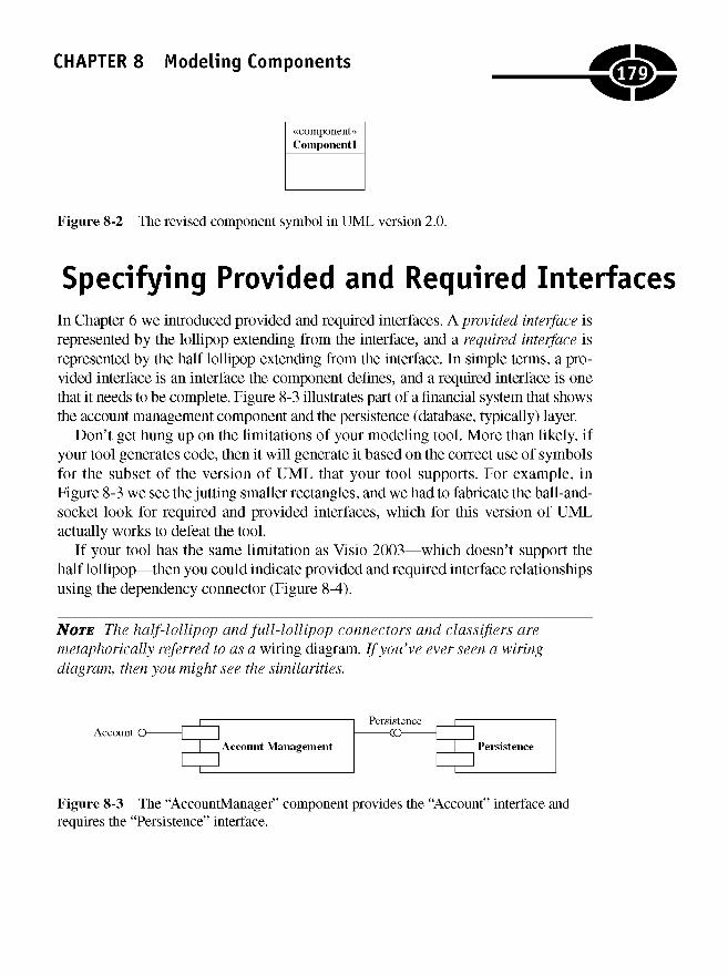
Figure 8-2 The revised component symbol in UML version 2.0.
Specifying Provided and Required InterfacesIn Chapter 6 we introduced provided and required interfaces. A provided interface isrepresented by the lollipop extending from the interface, and a required interface isrepresented by the half lollipop extending from the interface. In simple terms, a pro-vided interface is an interface the component defines, and a required interface is onethat it needs to be complete. Figure 8-3 illustrates part of a financial system that showsthe account management component and the persistence (database, typically) layer.
Don't get hung up on the limitations of your modeling tool. More than likely, ifyour tool generates code, then it will generate it based on the correct use of symbolsfor the subset of the version of UML that your tool supports. For example, inFigure 8-3 we see the jutting smaller rectangles, and we had to fabricate the ball-and-socket look for required and provided interfaces, which for this version of UMLactually works to defeat the tool.
If your tool has the same limitation as Visio 2003—which doesn't support thehalf lollipop—then you could indicate provided and required interface relationshipsusing the dependency connector (Figure 8-4).
NOTE The half-lollipop and full-lollipop connectors and classifiers aremetaphorically referred to as a wiring diagram. If you've ever seen a wiringdiagram, then you might see the similarities.
Figure 8-3 The "AccountManager" component provides the "Account" interface andrequires the "Persistence" interface.
179CHAPTER 8 Modeling Components
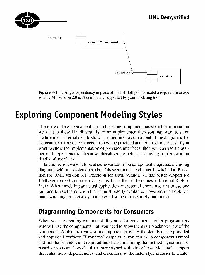
UML Demystified
Figure 8-4 Using a dependency in place of the half lollipop to model a required interfacewhen UML version 2.0 isn't completely supported by your modeling tool.
Exploring Component Modeling StylesThere are different ways to diagram the same component based on the informationwe want to show. If a diagram is for an implementer, then you may want to showa whitebox—internal details shown—diagram of a component. If the diagram is fora consumer, then you only need to show the provided and required interfaces. If youwant to show the implementation of provided interfaces, then you can use a classi-fier and dependencies—because classifiers are better at showing implementationdetails of interfaces.
In this section we will look at some variations on component diagrams, includingdiagrams with more elements. (For this section of the chapter I switched to Posei-don for UML version 3.1. Poseidon for UML version 3.1 has better support forUML version 2.0 component diagrams than either of the copies of Rational XDE orVisio. When modeling an actual application or system, I encourage you to use onetool and to use the notation that is most readily available. However, in a book for-mat, switching tools gives you an idea of some of the variety out there.)
Diagramming Components for Consumers
When you are creating component diagrams for consumers—other programmerswho will use the components—all you need to show them is a blackbox view of thecomponent. A blackbox view of a component provides the details of the providedand required interfaces. If your tool supports it, you can use a component symboland list the provided and required interfaces, including the method signatures ex-posed, or you can show classifiers stereotyped with «interface». Most tools supportthe realizations, dependencies, and classifiers, so the latter style is easier to create.
180
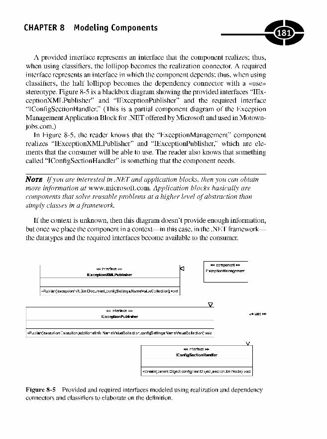
CHAPTER 8 Modeling Components
A provided interface represents an interface that the component realizes; thus,when using classifiers, the lollipop becomes the realization connector. A requiredinterface represents an interface in which the component depends; thus, when usingclassifiers, the half lollipop becomes the dependency connector with a «use»stereotype. Figure 8-5 is a blackbox diagram showing the provided interfaces "lEx-ceptionXMLPublisher" and "lExceptionPublisher" and the required interface"IConfigSectionHandler." (This is a partial component diagram of the ExceptionManagement Application Block for .NET offered by Microsoft and used in Motown-jobs.com.)
In Figure 8-5, the reader knows that the "ExceptionManagement" componentrealizes "lExceptionXMLPublisher" and "lExceptionPublisher," which are ele-ments that the consumer will be able to use. The reader also knows that somethingcalled "IConfigSectionHandler" is something that the component needs.
NOTE If you are interested in .NET and application blocks, then you can obtainmore information at www.microsoft.com. Application blocks basically arecomponents that solve reusable problems at a higher level of abstraction thansimply classes in a framework.
If the context is unknown, then this diagram doesn't provide enough information,but once we place the component in a context—in this case, in the .NET framework—the datatypes and the required interfaces become available to the consumer.
Figure 8-5 Provided and required interfaces modeled using realization and dependencyconnectors and classifiers to elaborate on the definition.
181
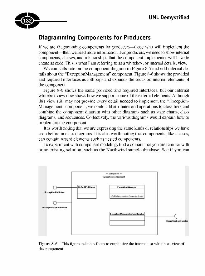
UML Demystified
Diagramming Components for Producers
If we are diagramming components for producers—those who will implement thecomponent—then we need more information. For producers, we need to show internalcomponents, classes, and relationships that the component implementer will have tocreate as code. This is what I am referring to as a whitebox, or internal details, view.
We can elaborate on the component diagram in Figure 8-5 and add internal de-tails about the "ExceptionManagement" component. Figure 8-6 shows the providedand required interfaces as lollipops and expands the focus on internal elements ofthe component.
Figure 8-6 shows the same provided and required interfaces, but our internalwhitebox view now shows how we support some of the external elements. Althoughthis view still may not provide every detail needed to implement the "Exception-Management" component, we could add attributes and operations to classifiers andcombine the component diagram with other diagrams such as state charts, classdiagrams, and sequences. Collectively, the various diagrams would explain how toimplement the component.
It is worth noting that we are expressing the same kinds of relationships we haveseen before in class diagrams. It is also worth noting that components, like classes,can contain nested elements such as nested components.
To experiment with component modeling, find a domain that you are familiar withor an existing solution, such as the Northwind sample database. See if you can
Figure 8-6 This figure switches focus to emphasize the internal, or whitebox, view ofthe component.
.182

CHAPTER 8 Modeling Components
describe a top-down view of a "componentized" version of elements of a customerorder-fulfillment system. (Of course, you can use any sample domain with which youare familiar.)
Quiz1. Every model should contain at least one component diagram.
a. True
b. False
2. A top-down approach to component diagrams means that you
a. define the components first and then decompose those components intoconstituent parts.
b. define the constituent parts and then place the components on top of theconstituent parts.
c. None of the above
3. A bottom-up approach to design can be valuable because (pick all that apply)
a. components aren't really needed.
b. you get more traction solving domain problems first.
c. building infrastructure is expensive and time-consuming.
d. domain classes always can be organized into components at a later time.
4. Component symbols can be represented using a classifier with the«component» stereotype.
a. True
b. False
5. A provided interface can be represented by a named lollipop
a. or a half lollipop.
b. or a dependency on a classifier with the «interface» stereotype.
c. or an «interface» stereotype on a classifier with a realization connector.
d. only by using the lollipop.
6. A required interface is an interface that the component realizes.
a. True
b. False
183

UML Demystified
7. A required interface can be represented by a named half lollipop
a. or a lollipop.
b. or a dependency on a classifier with the «interface» stereotype.
c. or an «interface» stereotype on a classifier with a realization connector.
d. only by using the half lollipop.
8. Components can contain nested components.
a. True
b. False
9. As a general rule, you only components and component diagrams for systemswith 100 or more domain classes.
a. True, but this is a general guideline. Components can help you to organizea solution and build reusable elements that can be sold separately.
b. False, because building components is always cheaper in Hie long run.
10. For each domain class in a component-based architecture, you may needthree to five supporting classes.
a. True
b. False
Answers1. b
2. a
3. b, c, and d
4. a
5. c
6. b
7. b
8. a
9. a
10. a
184
CHAPTER
Fit and Finish
I have worked on projects with budgets of less than $5 million that encompassed20,000 person-hours to projects with budgets of over a billion dollars and hundredsof thousands of person-hours. Some of these projects used almost no formal model-ing and design, and others used so much modeling and design that all forwardmomentum came to a halt. The lesson is that too little formality can result in a hacky,shoddy product and too much formality can result in a stalled or canceled project.
It is also worth mentioning that I have worked for huge companies that don't doany modeling but deliver software all the time. One has to wonder if the success ofthose projects is related to how much money those companies had to throw at theproblem and also whether the software would be better, faster, and cheaper if somemodeling and design had occurred.
The answer is somewhere in between. In general, software models need to be ascomplete and precise as the thing being designed. For example, if you are buildingsomething as complex as a doghouse, then you probably don't need much in theway of models. For something as complex as a house, you probably need models as
9
185
Copyright © 2005 by The McGraw-Hill Companies. Click here for terms of use.
UML Demystified
complex as a blueprint. Knowing the size, number of rooms, and building materialswill help you to size and budget a project while leaving some room for invention.For instance, variations in lighting fixtures, color of paint, style of carpeting, andthe precise placement of electrical outlets can be left (within reason) to the ingenu-ity of the specialists. For houses, specialists are carpenters, electricians, roofers,and plumbers; for software, specialists are programmers, testers, DBAs, and graph-ical user interface (GUI) designers.
The reality is that most software is more complex than a house, and much of it isbeing built without blueprints (UML models) that would adequately describea doghouse. The reason is that software modeling is new and hard. Further, code canbe compiled, debugged, run, and tested with results that are superficially meas-urable. In contrast, models aren't compiled but can only be "debugged" manually,are not run, and there is no simple way to test them. I would wager that very fewsoftware companies are doing code walk-throughs successfully, forget about Uni-fied Modeling Language (UML) walkthroughs.
What all this means is that if you are reading this, then you are ahead of many ofyour peers in terms of software modeling practices. It also means that defininga process and finding a balance between too much and too little modeling are im-portant. In this chapter I have provided some practical pointers in the context ofUML modeling and design that have helped me in the past. These pointers arebased on some projects that have succeeded and some that have failed. To help youfigure out how to complete your models, I will talk about
• A few basic dos and don'ts
• Using known patterns and refactorings
• When and how to add supporting documentation
• Validating your models
Modeling Dos and Don'tsI thought about naming this section "Modeling Best Practices" but dos and don'tsseems more demystifying.
I started modeling using the Booch notation in the early 1990s. In those days,there were few places you could go to learn a language such as C++ from a sea-soned pro and almost nowhere to learn modeling. This means that early on, thefew books I could get and my own mistakes were the only teachers available.Over more than a dozen years, I have gotten better, but there are still few bona
186

CHAPTER 9 Fit and Finish
fide modeling experts, and as far as I can tell, many universities still aren't offer-ing curricula for software architects (or even UML modelers); the art is too new.Consequently, the advice I can give you is based on my own intensive study andmany years of feeling my way. Clearly, this all suggests that your local expertmay disagree with my opinion. You know your own people better than I do; if youthink that something won't work or that my advice is questionable, then look tothose few wise old men whom everybody recognizes as experts: James Rum-baugh, Ivar Jacobson, Grady Booch, Erich Gamma, and Martin Fowler. There area few others, but you get the picture. When I have questions about the UML mod-eling, these are the folks I turn too.
Don't Keep Programmers Waiting
The first rule is: Don 't keep programmers waiting on models. This means that you mustdo a lot of design before you assemble your main programming team. A few program-mers available to help you prototype will be helpful, but don't staff up completely untilyou have a project plan and some of the analysis and design well under way.
Unfortunately, most projects aren't this organized. The whole team arrives, andthe pressure is on immediately to get everyone to work, including programmers.Try to create models that are detailed enough to get programmers working but notso detailed that they are stuck waiting. This is hard to do.
Work from a Macro View to a Micro View
Work on "big picture" items first. For example, identify the big parts of the systemfirst—Web GUI, custom macro language, Web services, and database persistence—before working on classes and lines of code. If you can figure out the parts and howthey fit together, then work can be divided by subsystems. This is a top-down ap-proach, but it supports a division of labor and gives you a context for smaller, moredetailed work.
Document Sparingly
Most documentation is part of the micro view. When modeling, keep in mind thatthe UML is a shorthand language for text. (You could design a whole system inplain English, right?) Analyze and design a solution as completely as needed withoutadding a lot of notes and documentation. Often, additional diagrams can clarifya diagram as readily as long-winded text.
187
UML Demystified
You also can save some of the documentation for the end of the project if yourmodels are hard deliverables. If your customer (internal or external) isn't paying forthe models, then spending resources polishing them may be a waste of your timeand money.
Find an Editor
Being a good UML modeler is not the same as being a good writer. In addition togetting a second set of eyes to look at your UML diagrams, hire an English major(or whatever language you speak) to review your documentation. Again, only dothis if models are hard deliverables.
Be Selective about Diagrams You Choose to CreateWhy did the chicken cross the road? The answer is probably because she could.Don't create diagrams because you can. Only create those that solve interestingproblems and only those that you really need. This approach also will help to elim-inate the waiting programmer problem.
Don't Count on Code Generation
James McCarthy cautions against "flipping the bozo bit"—as in "that guy is a bozo"—but if someone tells you that you are to model, model, model and flip a switchgenerating an executable, theny?zp that bozo bit. We are a decade or two away fromthe technology and education supporting generated applications. I have never seenthis approach work and have talked to several Rational consultants who agree withme. Code generation is a good idea, but we are a long way from automating softwaregeneration.
Model and Build from Most Risky to Least RiskySoftware usually has a few very important business cases and a bunch of supportingbusiness cases. The guiding principle is to build the hardest and most importantparts of the software first. Tackling the hard problems first helps you to avoid nastysurprises, and frequently, software can ship if the important business cases are
188
CHAPTER 9 Fit and Finish
supported even when some of the extra frills aren't so great. In my experience, thisis one of the biggest mistakes projects make: building easy things first.
If It's Obvious Don't Model It
Application blocks, components, third-party tools, and frameworks are all out ofyour control. All you can do is use them—unless you own these elements too,which is rare. Don't waste time modeling what you don't own. If you must modelthird-party tools in order to help developers use them, then model them as black-boxes: All you need to model is their presence and interfaces, and you only need tomodel the interfaces you are actually using. If your developers can use ADO.NETor the Data Access Application Block, for example, then simply indicate that youare using it. That's enough.
Emphasize Specialization
Another mistake is team member generalization. Software teams consist of gener-alists, but there is a tremendous amount of historical documentation and evidencethat specialization is a good thing: Adam Smith's Wealth of Nations, Henry Ford'sassembly lines, and the ancient Latin phrase "Divid et imperum." Dividing a prob-lem, intensity of focus, specialization, and building the critical elements first willtake you a long way on the road to success.
Using Known State PatternsPatterns are not an original idea or new. The application of patterns in softwareseems to originate from a 1977 book entitled, A Pattern Language, by ChristopherAlexander et al. Oddly enough, this book is about designing cities and towns, andpatterns such as green spaces. The green space pattern means that towns shouldhave parks.
It is certainly a clever extrapolation to turn a book about designing cities intoa concept that revolutionizes software—does it happen any other way than by ex-trapolation—but it has been demonstrated that good pattern usage helps to yieldgood software. The question is: Since software patterns are documented, do you
189

UML Demystified
need to add them to your UML diagrams when you use them in your designs? Theanswer is probably.
Software patterns are templates, but there is some latitude in how you implementthem. Each time a pattern is employed, you will have different class names basedon the solution domain, and many patterns can be implemented in different ways.For example, events and event handlers are an implementation of the observer pat-tern, but this is not precisely how observer is documented. Microsoft considers ASPpages and code-behind for ASP.NET an implementation of model-view-controller(MVC), but you won't see ASP.NET mentioned in the pattern definition. Thus theanswer is yes, in many instances, if you use a pattern, then you should incorporateit into your models to place it in the context of your problem domain. However, ifyou have a very experienced team, then you could just tell the developers to use theMVC, observer, or state pattern here.
TIP A good tip is to identify patterns when you use them. Identifying well-documented design patterns will eliminate or at least mitigate the need foryou to duplicate that documentation in your designs.
A good rule of thumb is that good software is based on patterns. The key is tolearn about design patterns, figure out key areas where they will help your design,and then incorporate them into your designs.
Figure 9-1 demonstrates how we can model the state behavior pattern, borrowingfrom the microwave oven in Chapter 7. This example demonstrates how we can
Figure 9-1 This figure is a classic implementation of the state behavior pattern for themicrowave oven example from Chapter 7.
190
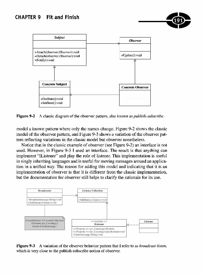
CHAPTER 9 Fit and Finish
Figure 9-2 A classic diagram of the observer pattern, also known as publish-subscribe.
model a known pattern where only the names change. Figure 9-2 shows the classicmodel of the observer pattern, and Figure 9-3 shows a variation of the observer pat-tern reflecting variations in the classic model but observer nonetheless.
Notice that in the classic example of observer (see Figure 9-2) an interface is notused. However, in Figure 9-3 I used an interface. The result is that anything canimplement "IListener" and play the role of listener. This implementation is usefulin singly inheriting languages and is useful for moving messages around an applica-tion in a unified way. The reason for adding this model and indicating that it is animplementation of observer is that it is different from the classic implementation,but the documentation for observer still helps to clarify the rationale for its use.
Figure 9-3 A variation of the observer behavior pattern that I refer to as broadcast-listen,which is very close to the publish-subscribe notion of observer.
191
UML Demystified
Refactoring Your ModelThis book is not the best forum for teaching design patterns or refactoring. TheUML is distinct from patterns, but patterns are described using the UML and text inother books. Refactoring is different from both the UML and patterns. While thereis some overlap between patterns and refactorings—e.g., Singleton and Factory areboth creational patterns and refactorings—refactoring is something that generally isdone after code has been written to improve the design of existing code. This said,there is no reason you cannot refactor models.
Suppose, for example, that you have a message signature in an interaction dia-gram that has several parameters. Before you release the diagram to your progra-mmers, you could apply the refactoring "Introduce Parameter Object." "IntroduceParameter Object" simply says to convert a long method signature into a short meth-od signature by introducing a class that contains all the parameters needed fora particular method and changing the method to accept an instance of that class.
There is no need to do anything other than introduce the parameter class andchange the method signature, but you would have to know about refactoring and thejustification for making this change. To learn more about refactoring, read Refac-toring: Improving the Design of Existing Code, by Martin Fowler, for more informationon this subject.
Patterns and refactorings are not part of the UML, but they will help you to createbetter UML diagrams. Good designs don't have to have grammatically perfectUML, but patterns and refactorings will make your designs better.
Adding Supporting DocumentationMany modeling tools will take any documentation that you create and combine itwith your diagrams and spit out high-quality—generally HyperText Markup Lan-guage (HTML)—cross-referenced and indexed model documentation. However, ifyou use a tool such as Excel, Word, Notepad, or something besides your UML toolto create your documentation, then you are defeating this feature of most tools.
I encourage you to convey as much meaning as possible with pictures. The simplereason is that pictures convey more information in a concise format than reams oftext. If you need text, then try constraints and notes in the model, but keep these to aminimum. Finally, if you must add a lot of documentation, don't hold the program-mers up while you write it. You will be lucky if the programmers even read your
1Q?

CHAPTER 9 Fit and Finish
models—the truth hurts—let alone long-winded text. Unfortunately, many program-mers are perfectly happy coding away whatever comes to mind or whatever theycoded on their last project. Complicated models may end up being ignored models.
Generally, for posterity, I like to include a written architectural overview ina separate document that describes the system at a high level. Some people just can'tor won't read models—think managers or even future programmers—but I createthese documents near the end of the project when everyone else is busy debuggingand testing.
Keep in mind that the UML and modeling are just one facet of software develop-ment. Modeling should help, not hinder, the overall process.
Validating Your ModelMany tools will validate models automatically. Unfortunately, every tool is different,and every tool seems to support different aspects of the UML. You can drive yourselfcrazy trying to remove bugs reported by validation tools from UML models.I wouldn't spend my time here. Period.
Your time will be better spent coding examples that show developers how toimplement the model, teaching developers how to read the models, and walkingthrough the models with the developers to see if they make sense and can be imple-mented. Generally, by the time you and the developers are happy with a particulardiagram, the program has most of what your diagram describes coded anyway.
Finally, just as I wouldn't ship code with warnings or errors, I don't want to shipmodels with warnings or errors either. If model validation is reporting an error, thenit usually means that I am using a feature inconsistently with the implementation ofthe UML my specific tool supports. Before I put a ribbon on a model and move onto something else, I will try to resolve discrepancies reported by validation tools.Historically, customers usually haven't been willing to pay for this effort, though.
Quiz1. A model is only complete when it contains at least one of every kind
of diagram.
a. True
b. False
193
UML Demystified
2. Component diagrams are absolutely necessary.
a. True
b. False
3. I must pick either a top-down or a bottom-up approach to modeling butcannot combine techniques.
a. True
b. False
4. Specialization has been argued to yield productivity gains.
a. True
b. False
5. Design patterns are part of the UML specification.
a. True
b. False
6. Refactoring is not part of the UML specification.
a. True
b. False
7. Most experts agree that patterns and refactorings will improve theimplementation of software.
a. True
b. False
8. The UML is a standard, and everyone agrees that it should be used.
a. True
b. False
9. Using a tool to validate models is essential.
a. True
b. False
10. All UML modeling tools are capable of effectively generating entire,complete applications.
a. True
b. False
.194

CHAPTER 9 Fit and Finish
Answers1. b
2. b
3. b
4. a
5. b
6. a
7. a
8. b
9. b
10. b
195

This page intentionally left blank

CHAPTER
Visualizing YourDeployment
Topology
Deployment topology simply means what your system will look like when you putit into use. You can diagram what your system will look like when deployed witha deployment diagram. Deployment diagrams will show the reader the logical ele-ments, their physical locations, and how these elements communicate, as well asthe number and variety of physical and logical elements.
Use deployment diagrams to show where your Web server is and whether youhave more than one. Use deployment diagrams to show where you database server isand whether you have more than one and what the database server's relationship(s)is(are) to other elements. Deployment diagrams can show how these elements areconnected, what protocols the elements are using to communicate, and what operatingsystems or physical devices, including computers and other devices, are present.
10
197
Copyright © 2005 by The McGraw-Hill Companies. Click here for terms of use.

UML Demystified
Clearly, the implication is that if you don't have most of these elements, then youprobably don't need to create a deployment diagram. If you are creating a simplestand-alone application or even a simple single-user database application, a Web site,console application, or service, then you can skip creating a deployment diagram.
Deployment diagrams are not that hard to create, don't generally contain a largenumber of elements, and are only needed for medium- to large-complexity applica-tions. What deployment diagrams are good at doing is visualizing the landscape of yourdeployment for systems with multiple elements. You are certainly welcome to createa deployment diagram for every model, but here is an area where I would economize.
Modeling NodesNodes are three-dimensional boxes that represent physical devices that can but don'thave to be computers or execution environments that can be computers, operatingsystems, or containing environments such as COM+, IIS, or an Apache server.
Physical devices commonly include computers, but they can include any physicaldevice. Working on a project for Lucent Technologies years ago, I was writing soft-ware for hoteling phones—moving phone settings from phone to phone and controllingswitching systems. In my deployment diagram, I showed computers, phones, andphone switches. More recently, I was working on a project for Pitney Bowes. I waswriting a multinational shipping framework to support the concept of a universal car-rier. Much of that framework used MSMQ—COM+ messaging queuing—sothe deployment diagram reflected nodes that represented a COM+ executionenvironment.
The basic symbol for a node is a three-dimensional cube with the node name in thecube (Figure 10-1). If you wanted to model several nodes of the same type, then youcould use a tag indicating the number of occurrences of that node, or you could add
Figure 10-1diagram.
A single-named node in a Unified Modeling Language (UML) deployment
iEM
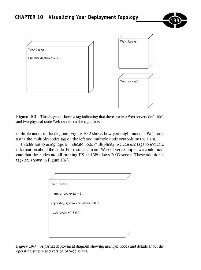
CHAPTER 10 Visualizing Your Deployment Topology
Figure 10-2 This diagram shows a tag indicating that there are two Web servers (left side)and two physical node Web servers on the right side.
multiple nodes to the diagram. Figure 10-2 shows how you might model a Web farmusing the multiple-nodes tag on the left and multiple node symbols on the right.
In addition to using tags to indicate node multiplicity, we can use tags to indicateinformation about the node. For instance, in our Web server example, we could indi-cate that the nodes are all running IIS and Windows 2003 server. These additionaltags are shown in Figure 10-3.
Figure 10-3 A partial deployment diagram showing multiple nodes and details about theoperating system and version of Web server.
199
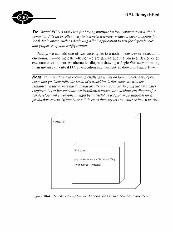
UML Demystified
TIP Virtual PC is a tool I use for having multiple logical computers on a singlecomputer. It is an excellent way to test beta software or have a clean machine forlocal deployment, such as deploying a Web application to test for dependenciesand proper setup and configuration.
Finally, we can add one of two stereotypes to a node—«device» or «executionenvironment—to indicate whether we are talking about a physical device or anexecuton environment. An alternative diagram showing a single Web server runningin an instance of Virtual PC, an execution environment, is shown in Figure 10-4.
NOTE An interesting and recurring challenge is that on long projects developerscome and go. Generally, the result of a transition is that someone who hasremained on the project has to spend an afternoon or a day helping the newcomerconfigure his or her machine. An installation project or a deployment diagram forthe development environment might be as useful as a deployment diagram for aproduction system. (If you have a little extra time, try this out and see how it works.)
Figure 10-4 A node showing Virtual PC being used as an execution environment.
200

CHAPTER 10 Visualizing Your Deployment Topology
Showing Artifacts in NodesArtifacts are the things you are deploying. (If you are combining hardware and soft-ware development, then you might be deploying your own nodes too, but I am talkingjust about software.) Artifacts are modeled using the class symbol and an «artifact»stereotype. Artifacts can be .EXEs, .DLLs, HTML files, documents, JAR files, as-semblies, scripts, binary files, or anything else you deploy as part of your solution.Commonly, binary artifacts are components, and we can use a tag to specify whichcomponent an artifact represents. Figure 10-5 shows an artifact representing a .DLL,and Figure 10-6 shows how we would place that artifact in a node.
Traditionally, you might find some overlap between component diagrams anddeployment diagrams. For example, if an artifact implements a component, you canshow the component implemented as a tag, or you can add the component to thenode showing the dependency between the artifact and the component. Figure 10-7shows the component tag used to indicate that the shown artifact implements the"ExceptionManagement" component used, and Figure 10-8 shows the same thing us-ing the more verbose dependency attached to a component symbol. (The «manifest»stereotype means that the artifact is a manifestation of the component.)
NOTE Dependencies also can be used between artifacts to indicate that oneartifact is dependent on a second. This supports the notion of references in .NET,uses in Delphi, and includes C++. For example, the "ExceptionManagement.dll"has a dependency on the "System.dll" (not shown) that contains the "EventLog"class in .NET.
As an alternative to placing several nested class diagrams in a single node, theUML supports listing artifacts as text. For example, an ASP.NET-based Web sitewill contain a binary, several .ASPX files containing HTML and ASP, and possiblyother documents or elements such as script. Using the class symbol for more than
Figure 10-5 An artifact representing a binary that is the executable supporting a Web site.
201

UML Demystified
Figure 10-6 In deployment diagrams, artifacts are deployed to nodes, so we can showan artifact nested in a node.
Figure 10-7 Specifying the component an artifact implements using a tag.
202
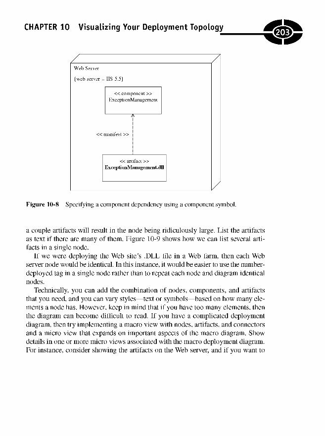
CHAPTER 10 Visualizing Your Deployment Topology
Figure 10-8 Specifying a component dependency using a component symbol.
a couple artifacts will result in the node being ridiculously large. List the artifactsas text if there are many of them. Figure 10-9 shows how we can list several arti-facts in a single node.
If we were deploying the Web site's .DLL file in a Web farm, then each Webserver node would be identical. In this instance, it would be easier to use the number-deployed tag in a single node rather than to repeat each node and diagram identicalnodes.
Technically, you can add the combination of nodes, components, and artifactsthat you need, and you can vary styles—text or symbols—based on how many ele-ments a node has. However, keep in mind that if you have too many elements, thenthe diagram can become difficult to read. If you have a complicated deploymentdiagram, then try implementing a macro view with nodes, artifacts, and connectorsand a micro view that expands on important aspects of the macro diagram. Showdetails in one or more micro views associated with the macro deployment diagram.For instance, consider showing the artifacts on the Web server, and if you want to
203
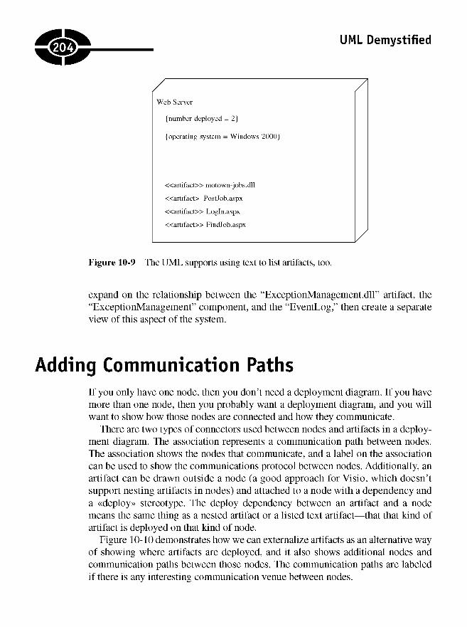
UML Demystified
Figure 10-9 The UML supports using text to list artifacts, too.
expand on the relationship between the "ExceptionManagement.dll" artifact, the"ExceptionManagement" component, and the "EventLog," then create a separateview of this aspect of the system.
Adding Communication PathsIf you only have one node, then you don't need a deployment diagram. If you havemore than one node, then you probably want a deployment diagram, and you willwant to show how those nodes are connected and how they communicate.
There are two types of connectors used between nodes and artifacts in a deploy-ment diagram. The association represents a communication path between nodes.The association shows the nodes that communicate, and a label on the associationcan be used to show the communications protocol between nodes. Additionally, anartifact can be drawn outside a node (a good approach for Visio, which doesn'tsupport nesting artifacts in nodes) and attached to a node with a dependency anda «deploy» stereotype. The deploy dependency between an artifact and a nodemeans the same thing as a nested artifact or a listed text artifact—that that kind ofartifact is deployed on that kind of node.
Figure 10-10 demonstrates how we can externalize artifacts as an alternative wayof showing where artifacts are deployed, and it also shows additional nodes andcommunication paths between those nodes. The communication paths are labeledif there is any interesting communication venue between nodes.
204
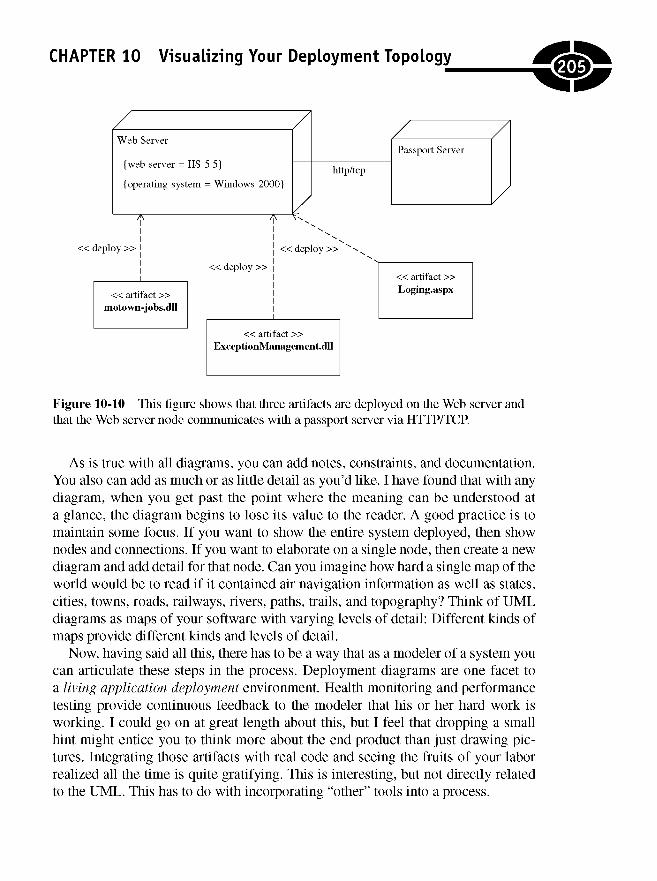
CHAPTER 10 Visualizing Your Deployment Topology
Figure 10-10 This figure shows that three artifacts are deployed on the Web server andthat the Web server node communicates with a passport server via HTTP/TCP.
As is true with all diagrams, you can add notes, constraints, and documentation.You also can add as much or as little detail as you'd like. I have found that with anydiagram, when you get past the point where the meaning can be understood ata glance, the diagram begins to lose its value to the reader. A good practice is tomaintain some focus. If you want to show the entire system deployed, then shownodes and connections. If you want to elaborate on a single node, then create a newdiagram and add detail for that node. Can you imagine how hard a single map of theworld would be to read if it contained air navigation information as well as states,cities, towns, roads, railways, rivers, paths, trails, and topography? Think of UMLdiagrams as maps of your software with varying levels of detail: Different kinds ofmaps provide different kinds and levels of detail.
Now, having said all this, there has to be a way that as a modeler of a system youcan articulate these steps in the process. Deployment diagrams are one facet toa living application deployment environment. Health monitoring and performancetesting provide continuous feedback to the modeler that his or her hard work isworking. I could go on at great length about this, but I feel that dropping a smallhint might entice you to think more about the end product than just drawing pic-tures. Integrating those artifacts with real code and seeing the fruits of your laborrealized all the time is quite gratifying. This is interesting, but not directly relatedto the UML. This has to do with incorporating "other" tools into a process.
205
UML Demystified
Quiz1. A node always represents a physical device.
a. True
b. False
2. A node can represent (pick all that apply)
a. a computer.
b. any physical device.
c. an execution context such as an application server.
d. all the above.
3. The stereotypes that apply to nodes can be (pick all that apply)
a. «device».
b. «component».
c. «exceutionenvironment».
d. «manifest».
4. Tags are used to add details to a node.
a. True
b. False
5. A database server is an example of a node.
a. True
b. False
6. Artifacts use which symbol?
a. Package
b. Class
c. Activity
d. Object
7. An artifact can be represented as text in a node, a class in a node, and witha realization connector and an external class symbol.
a. True
b. False
206

CHAPTER 10 Visualizing Your Deployment Topology
8. The connector and stereotype for an artifact shown outside a node is
a. realization and manifest.
b. dependency and deploy.
c. association and deploy.
d. dependency and manifest.
9. When an artifact is shown connected to a component, which stereotype applies?
a. «deploy»
b. «use»
c. «manifest»
d. «extends»
10. Which connector is used to show communication between nodes?
a. Dependency
b. Generalization
c. Association
d. Link
Answers1. a
2. d
3. a and c
4. a
5. a
6. b
7. b
8. b
9. c
10. d
207

This page intentionally left blank
APPENDIX
Final Exam
1. What does the acronym UML mean?
a. Uniform Model Language
b. Unified Modeling Language
c. Unitarian Mock-Up Language
d. Unified Molding Language
2. The UML is only used to model software.
a. True
b. False
3. What is the name of the process most closely associated with the UML?
a. The modeling process
b. The rational unified process
c. Extreme programming
d. Agile methods
A
209
Copyright © 2005 by The McGraw-Hill Companies. Click here for terms of use.
UML Demystified
4. What is the name of the standards body that defines the UML?
a. Unified Modeling Group
b. Object Modeling Group
c. Object Management Group
d. The Four Amigos
5. Use case diagrams are used to capture macro descriptions of a system.
a. True
b. False
6. Differentiate between sequence diagrams and collaboration diagrams(choose all that apply).
a. Sequence diagrams are interaction diagrams; collaboration diagramsare not.
b. Sequence diagrams represent a time ordering; collaboration diagramsrepresent classes and messages, but time ordering is not implied.
c. Time order is indicating by numbering sequence diagrams.
d. None of the above
7. A class diagram is a dynamic view of the classes in a system.
a. True
b. False
8. A good UML model will contain at least one of every kind of diagram.
a. True
b. False
9. What is the nickname of the group of scientists who are most notablyassociated with the UML?
a. The Gang of Four
b. The Three Musketeers
c. The Three Amigos
d. The Dynamic Duo
10. Sequence diagrams are good at showing the state of an object across manyuse cases.
a. True
b. False
210
APPENDIX A Final Exam
11. What symbol represents an actor?
a. Aline
b. A directed line
c. A stick figure
d. An oval containing text
12. An actor can be a person or something that acts on a system.
a. True
b. False
13. What symbol represents an association (pick the best answer)?
a. Aline.
b. A line with a triangle pointing at the dependent element.
c. A dashed line with an arrow pointing at the dependent element.
d. A dashed line with an arrow pointing at the depended-on element.
14. Stereotypes are more common on
a. actors.
b. connectors.
c. use cases.
d. None of the above.
15. An inclusion relationship is used for modeling optional features reusingbehavior modeled by another use case.
a. True
b. False
16. An extension relationship is used for modeling behavior captured byanother use case.
a. True
b. False
17. Generalization is synonymous with
a. polymorphism.
b. aggregation.
c. inheritance.
d. interfaces.
211
UML Demystified
18. Every capability of a system must be represented by a use case.
a. True
b. False
19. In an includes relationship, the arrow points at the
a. base use case.
b. inclusion use case.
20. It is important to implement the hard use cases first to mitigate risk early.
a. True
b. False
21. Synonyms for a transition are connector and flow.
a. True
b. False
22. In general, activity diagrams consist of (pick all that apply)
a. nodes.
b. transitions.
c. decisions.
d. edges.
23. Exceptions are not supported in activity diagrams.
a. True
b. False
24. A join and merge node use
a. different symbols.
b. identical symbols.
c. either identical or differing symbols depending on context.
d. All nodes symbols are the same.
25. Multiple flows entering an action node are not
a. an implicit merge.
b. an implicit join.
.212

APPENDIX A Final Exam
26. Flows wait at a merge until
a. all flows have arrived.
b. the first flow has arrived.
c. you tell it to leave.
d. It depends.
27. The swimlane metaphor is still in use.
a. True
b. False
28. Actions can exist in only one activity partition at the same time.
a. True
b. False
29. A join and fork node is represented by
a. an oval.
b. a circle.
c. a rectangle.
d. a diamond.
30. Activity diagrams are identical to flowcharts.
a. True
b. False
31. A collaboration diagram is an example of
a. a sequence diagram.
b. a class diagram.
c. an activity diagram.
d. an interaction diagram.
32. A collaboration diagram shows how an object's state evolves over manyuse cases.
a. True
b. False
213
UML Demystified
33. Collaboration diagrams were renamed communication diagrams in theUML version 2.0.
a. True
b. False
34. Sequence diagrams cannot be used to model asynchronous and multithreadedbehavior.
a. True
b. False
35. Interaction frames use a (fill in the blank) to control when andwhich fragment of the frame to execute.
a. merge
b. join
c. guard
d. asynchronous message
36. The alt interaction frame is used to
a. model optional behavior.
b. model multithreaded behavior.
c. model conditional logic.
d. capture error conditions.
37. Sequence diagrams and communication diagrams show complementaryviews.
a. True
b. False
38. An activation symbol shows
a. the lifetime of an object in a communication diagram.
b. object creation.
c. the lifetime of an object in a sequence diagram.
d. object destruction.
39. A nested numbering scheme is valid UML used in
a. sequence diagrams.
b. activity diagrams.
c. use cases.
d. communication diagrams.
214

APPENDIX A Final Exam
40. Sequence diagrams are perfect for modeling lines of code.
a. True
b. False
41. The same basic symbol is used for enumerations and interfaces.
a. True
b. False
42. When adding classes to a diagram, you should show fields and
a. methods.
b. fields only.
c. properties.
d. properties and methods.
43. A property can be modeled as a feature of a class and
a. a subclass.
b. an association class.
c. a dependent class.
d. an interface.
44. When modeling attributes, it is
a. required that you model attribute methods.
b. recommended that you not show attribute methods.
c. recommended that you show the underlying fields for those attributes.
d. None of the above
45. Simple types should be modeled as features and complex types as (pick thebest one)
a. features too.
b. association classes.
c. attributes.
d. features or association classes.
46. A unidirectional association has an arrow at one end called the source. Theother end is called the target.
a. True
b. False
215
UML Demystified
47. An aggregation is most like
a. inheritance.
b. association.
c. composition.
d. generalization.
48. What is the most important difference between an aggregation andcomposition?
a. Composition means that the whole, or composite, class will beresponsible for creating and destroying the part or contained class.
b. Aggregation means that the whole, aggregate class will be responsiblefor creating and destroying the part or contained class.
c. Composition means that the whole, or composite, class is the only classthat can have an instance of the part class at any given time.
d. Aggregation means that the whole, or aggregate, class is the only classthat can have an instance of the part class at any given time.
e. a and c
f. b and d
49. Realization means
a. polymorphism.
b. association.
c. interface inheritance.
d. composition.
50. A named association is modeled as a
a. method.
b. property.
c. field and property.
d. dependency.
51. A subclass has access to a superclass's protected members.
a. True
b. False
52. A child class may only have one parent class.
a. True
b. False
.216

APPENDIX A Final Exam
53. Which of the following statements is false?
a. Generalization refers to subtypes.
b. Classification refers to subtypes.
c. Generalization refers to object instances.
d. Classification refers to object instances.
e. None of the above
54. Realization refers to
a. class inheritance.
b. interface inheritance.
c. promoting the constituent members in a composite class.
d. aggregation.
55. Multiple inheritance can be approximated through
a. an association and the promotion of constituent properties.
b. realization.
c. composition and the promotion of constituent properties.
d. aggregation and the promotion of constituent properties.
56. Dynamic classification—where an object's type changed at runtime—canbe modeled using
a. generalization.
b. association.
c. realization.
d. composition.
57. An association class is not referred to as a linking class.
a. True
b. False
58. A parameter used to return a unique type is called
a. a realization.
b. an association qualifier.
c. an association postcondition.
d. directed association.
217
UML Demystified
59. Pick the correct statements.
a. A provided interface means that a class implements an interface.
b. A required interface means that a class depends on an interface.
c. A provided interface means that a class depends on an interface.
d. A required interface means that a class implements an interface.
60. When a classifier symbol is underlined, it means that
a. the symbol represents an object.
b. the symbol represents an abstract class.
c. the symbol represents an interface.
d. the symbol is a derived value.
61. State charts (or state machine diagrams) are good for
a. diagramming systems.
b. diagramming objects and messages for a single use case.
c. understanding a single use case.
d. specifying the behavior of an object across several use cases.
62. State machines should not be used to explore graphical user interfaces(GUIs) and real-time controllers.
a. True
b. False
63. A junction is used to
a. merge several incoming transitions to a single outgoing transition.
b. split a single incoming transition into several outgoing transitions.
c. Both a and b
d. None of the above
64. History pseudostates are used to restore previous states.
a. True
b. False
65. A do activity executes
a. over time and a regular activity executes immediately but can beinterrupted.
b. immediately and a regular activity executes over time but can beinterrupted.
218

APPENDIX A Final Exam
c. over time and can be interrupted, and a regular activity executesimmediately.
d. over time and a regular activity executes immediately but cannot beinterrupted.
66. Transitions are directed lines labeled with
a. an optional trigger, an event, and an effect.
b. a trigger, an optional event, and an effect.
c. a trigger, an event, and an optional effect.
d. a trigger, an event, and an effect optionally.
67. External transitions cause an enter and exit activity to be executed.
a. True
b. False
68. Self-transitions cause an enter and exit activity to be executed.
a. True
b. False
69. A composite orthogonal state
a. is divided into regions, and only one region can be active at a time.
b. is divided into regions, and only one substate can be active at a time.
c. is divided into regions, and only one substate per region can be active ata time.
d. is composed of a single region, and multiple substates can be activesimultaneously.
70. A composite nonorthogonal state
a. is comprised of regions, and only one region can be active at a time.
b. is not divided into regions, and only one substate can be active at a time.
c. is not divided into regions, and multiple substates can be active at a time.
d. is divided into regions, and one substate per region can be active at a time.
71. Every model should contain at least one component diagram.
a. True
b. False
219
UML Demystified
72. A bottom-up approach to component diagrams means that you
a. define the components first and decompose those components intoconstituent parts.
b. define the constituent parts and place the components on top of theconstituent parts.
c. Neither of the above
73. A bottom-up approach to design can be valuable because (pick allthat apply)
a. components aren't really needed.
b. you get more traction solving domain problems first.
c. building infrastructure is expensive and time-consuming.
d. domain classes always can be organized into components at alater time.
74. Component symbols can be represented using a classifier with the«component» stereotype.
a. True
b. False
75. A required interface can be represented by a named half lollipop
a. or a lollipop.
b. or a dependency on a classifier with the «interface» stereotype.
c. or by connecting to an interface with a dependency.
d. only by using the half lollipop.
76. A provided interface is an interface that a component realizes.
a. True
b. False
77. A required interface can be represented by a named half lollipop and isequivalent to a dependency between a component and an interface.
a. True
b. False
78. Components may not contain nested components.
a. True
b. False
a220

APPENDIX A Final Exam
79. As a general rule, you only use components and component diagrams forsystems with 100 or more domain classes.
a. True, but this is a general guideline. Components can help you organizea solution and build reusable elements that can be sold separately.
b. False, because building components is always cheaper in the long run.
80. For each domain class in a component-based architecture, you may needtwo to three supporting classes.
a. True
b. False
81. A model is only complete when it contains at least one of every kind ofdiagram.
a. True
b. False
82. Component diagrams are only needed for large systems.
a. True
b. False
83. I must pick either a top-down or a bottom-up approach to modeling butcannot combine techniques.
a. True
b. False
84. Specialization has been argued to yield productivity gains.
a. True
b. False
85. Design patterns are not part of the UML specification.
a. True
b. False
86. Refactoring is part of the UML specification.
a. True
b. False
87. Few experts agree that patterns and refactorings will improve theimplementation of software.
a. True
b. False
221
UML Demystified
88. The UML is a standard, and everyone agrees that it should be used.
a. True
b. False
89. Using a tool to validate models is essential.
a. True
b. False
90. All UML modeling tools are capable of effectively generating entire,complete applications.
a. True
b. False
91. A node always represents a physical device.
a. True
b. False
92. A node can represent (pick all that apply)
a. a computer.
b. any physical device.
c. an execution context such as an application server.
d. All the above
93. The stereotypes that apply to nodes are (pick all that apply)
a. «device».
b. «component».
c. «executionenvironment».
d. «manifest».
94. Tags are not used to add details to a node.
a. True
b. False
95. A database server is an example of a node.
a. True
b. False
96. Artifacts use which symbol?
a. Package
b. Class
.22
APPENDIX A Final Exam
c. Activity
d. Object
97. An artifact can be represented as text in a node, a class in a node, and witha realization connector and an external class symbol.
a. True
b. False
98. The connector and stereotype for an artifact shown outside a node is
a. realization and manifest.
b. dependency and deploy.
c. association and deploy.
d. dependency and manifest.
99. When an artifact is shown connected to a component, which stereotypeapplies?
a. «deploy»
b. «use»
c. «manifest»
d. «extends»
100. Which connector is used to show communication between nodes?
a. Dependency
b. Generalization
c. Association
d. Link
Answers1. b 7. b 13. a
2. b 8. b 14. b
3. b 9. c 15. b
4. c 10. b 16. b
5. a 11. c 17. c
6. b 12. a 18. b
223
UML Demystified
19. b
20. a
21. b
22. aandd
23. b
24. a
25. a
26. a
27. a
28. b
29. c
30. b
31. d
32. b
33. a
34. b
35. c
36. c
37. b
38. c
39. d
40. b
41. a
42. a
43. b
44. b
45. d
46. a
47.
48.
49.
50.
51.
52.
53.
54.
55.
56.
57.
58.
59.
60.
61.
62.
63.
64.
65.
66.
67.
68.
69.
70.
71.
72.
73.
74.
c7
C
C
a
b
b andc
b
c
b
b
b
a andb
a
d
b
c
a
c
d
a
a
c
b
b
b
b, c, and d
a
75. c
76. a
77. a
78. b
79. a
80. b
81. b
82. b
83. b
84. a
85. a
86. b
87. b
88. b
89. b
90. b
91. b
92. d
93. a andc
94. b
95. a
96. b
97. b
98. b
99. c
100. c
224
SELECTEDBIBLIOGRAPHY
Ambler, Scott. The Object Primer: Agile Model-Driven Development with UML2.0,3d ed. New York: Wiley, 2004.
Booch, Grady. Object Solutions. Reading, MA: Addison-Wesley, 2005.Booch, Grady, Ivar Jacobson, and James Rumbaugh. The Unified Modeling
Language, 2d ed. Reading, MA: Addison-Wesley, 2005.Eriksson, Hans-Erik, Magnus Penker, Brian Lyons, and David Fado. UML 2 Toolkit.
Indianapolis: Wiley, 2004.Fowler, Martin. UML Distilled Third Edition: A Brief Guide to the Standard Object
Modeling Language. Reading, MA: Addison-Wesley, 2004.Love, John F. McDonald's: Behind the Arches. New York: Bantam, 1995.Overgaard, Gunnar, and Karen Palmkvist. Use Cases: Patterns and Blueprints.
Reading, MA: Addison-Wesley, 2005.
225
Copyright © 2005 by The McGraw-Hill Companies. Click here for terms of use.

This page intentionally left blank
INDEX
Symbols« and » (guillemots), 24- (minus) symbol, 107+ (plus) symbol, 107# (pound) symbol, 107
AAccept signal (activity diagrams), 67Action nodes (activity diagrams), 52, 53, 56-62
adding preconditions/postconditions,58-62
modeling subactivities, 62naming actions, 57-58
Activating lifelines, 84-85Active states, 161-162Activities (state chart diagrams), 165Activity diagrams, 7-8, 47-77
action nodes, 56-62actions that span partitions, 67control flow, 52, 53creating, 72-73decision nodes, 62-63determining number of, 77examples of, 51flowcharts vs., 48, 51forks, 63goal of, 47guard conditions, 52-54
initial node, 52input parameters, 70joins, 63merge nodes, 62-64multidimensional partitions, 67, 68naming actions, 57-58partitioning responsibility, 63-68preconditions and postconditions, 58-62in reengineering process, 73-76showing exceptions in, 70, 71showing flows in, 54-56subactivities, 62swimlanes, 63-68terminating, 71-72time signal, 67-69uses of, 48, 49-51
Activity final node (activity diagrams), 71-72Activity partitions (See Swimlanes [activity
diagrams])Actor symbols, 7, 21
defining, 36-39Esaw, 1,2, 10, 11function of, 18lifelines attached to, 83, 84
Aggregation relationships, 112-114, 143(See also Composition relationships)
Agile process, 14, 92Alexander, Christopher, 189
227
Copyright © 2005 by The McGraw-Hill Companies. Click here for terms of use.
UML Demystified
Alternative interaction frame, 90, 91Ambler, Scott, 176Ancestor (as term), 132Annotations:
class diagrams, 118use case diagrams, 27-28 (See also
Documentation [use case diagrams])Arrays:
association, 145-147attribute, 110, 111
Artifacts (deployment diagrams), 201-204,204,205
Association classes, 146-150directed, 146, 151qualified, 147
Association relationships, 145-150class diagrams, 108-109, 112, 113use cases, 22
Attributes, 103arrays and multiplicity, 110, 111with association, 108-109in classifier symbol, 106, 107declaring, 107-108, 107-109decorating, 106-107primitives as, 121uniqueness of, 110-111using, 107-111
Automobile engineering, 4
BBabbage, Charles, 4Balancing Agility and Discipline
(Barry Boehm), 14Base class, 114Behavior state machines, 159, 166-167Behaviors, 103Behind the Golden Arches, 73Boehm, Barry, 14Booch, Grady, 4, 187Bottom-up design approach, 178Boundary classes, 124, 125, 128Broccoli, Albert, 136
CC++, 4The C++ Programming Language (Gjarne,
Stroustrop), 152Call events, 164Change events, 164Child (as term), 114, 132Chitty Chitty Bang Bang (film), 136-137Choice state, 159, 160Class diagrams, 8-9, 101-128
adding details to classes, 153adding operations to classes,
111,112attributes, 107-111boundary classes, 128classifier, 103-107comments, 118constraints, 118-120control classes, 127datatypes, 105decorating classes, 106-107entity classes, 126-127enumerations, 121-122features, 103generic types, 105identifying classes needed, 123-128interfaces, 104-105metaclasses, 105-106namespaces, 122-123notes, 118, 119object diagrams, 104packages, 118parameterized types, 105primitives, 120-121relationships in, 111, 113-117stereotypes, 117
Class responsibility and collaborator (CRC)cards, 125-126
Classes:adding details to, 153association, 146-150
228

INDEX
boundary, 124, 125, 128in class diagrams, 8-9classifiers, 103-107control, 124, 125, 127decorating, 106discovering, 102domain, 176entity, 124, 125, 126-127features of, 103lifeline representing, 84metaclasses, 105-106relationships among (See Relationships)simple, 104
Classification:dynamic, 133-136generalization vs., 132-133
Classifier role (collaboration diagrams), 94Classifiers, 103-107
attributes in, 106, 107half- and full-lollipop, 179operations in, 111
Cobol, 4Coding, initiation of, 96-97Collaboration (communication) diagrams,
9,11,82,94-95Combined fragments (See Interaction frames)Comments (class diagrams), 118Communication diagrams (See Collaboration
diagrams)Communication paths (deployment diagrams),
204-205Completion transition, 164Component diagrams, 11-12, 175-182
bottom-up design approach, 178for consumers, 180-181for producers, 182-183specifying interfaced, 179-180top-down design approach, 177
Components, 176Composite states, 162-163Composition relationships, 112-114, 143-145
Computers, history of, 4Connector nodes (activity diagrams), 54-55Connectors:
class diagrams, 112-117collaboration diagrams, 94deployment diagrams, 204half- and full-lollipop, 179stereotypes associated with, 117use case diagrams, 22-25
Constraints:class diagrams, 118-120sequence diagrams, 87
Consumers, component diagrams for, 180-181Control classes, 124, 125, 127Control flow (activity diagrams), 52, 53CRC cards (See Class responsibility and
collaborator cards)Create, read, update, and delete (CRUD)
behavior, 51Creational patterns, 133CRUD (create, read, update, and delete)
behavior, 51Customers, communicating with, 20
DDatatypes, 105Decision diamonds (flowcharts), 62Decision nodes (activity diagrams), 56, 62-63Decorating classes, 106-107Deep history state, 160, 161Dependency relationships, 150-152
class diagrams, 112, 116-117extend stereotypes, 26-27include stereotypes, 25-26inserting references to, 32stereotypes for, 151-152use cases, 22, 25-27, 32
Deployment topology diagrams, 12, 197-205communication paths, 204-205nodes on, 198-200showing artifacts in nodes, 201-205
229
UML Demystified
Design:bottom-up, 178top-down, 177use case-driven, 43-44
Design by contract, 58, 59Design patterns, 127, 133-134Design Patterns (Erich Gamma), 97, 127,
133,171Diagrams, 7-12
activity, 7-8choosing, 188class, 8-9component, 11-12deployment topology, 12interaction, 9-10size and complexity of, 13state, 10, 11text supplementing, 13use case, 7when to create, 12
Directed association, 146, 151Directed/directional association, 113Do activities, 161-162Documentation (in general):
amount of, 187-188editing of, 188with models, 192-193(See also Comments; Notes)
Documentation (use case diagrams),13,28-32, 42
forms of, 28notes as, 27-28outlines for, 29-32of primary and secondary
requirements, 20Domain classes, 176Domain experts, 49, 125Dynamic classification, 133-136
EEckert, Presper, 4Edge (See Control flow)Editing of documentation, 188Entity classes, 124, 125, 126-127Enumerations (class diagrams), 121-122Esaw, 1,2, 10, 11Exception handler (activity diagrams), 70, 71Exceptions (activity diagrams), 70, 71Extension use case, 25-27extreme Programming (XP), 6, 14
FFeature(s):
of classes, 103meaning of term, 106, 107as processes, 48symbols identifying, 107
Feedback,13Fields, 107, 145Final state, 159Fleming, Ian, 136Flow (See Control flow)Flow final node (activity diagrams), 71-72Flowcharts:
activity diagrams vs., 48, 51decision diamonds in, 62
Fork nodes (activity diagrams), 56, 63Found messages, 85Fowler, Martin, 97, 187, 192Full-lollipop, 179
GGamma, Erich, 97, 127, 133, 171, 187Gates, Bill, 3Generalization relationships:
class diagrams, 112, 114, 115use cases, 22, 23(See also Inheritance relationships)
230
INDEX
Generics, 105Grammar, 102-103Grandchild (as term), 132Guard conditions:
activity diagrams, 52-54, 58-62sequence diagrams, 90state chart diagrams, 164, 165
Guillemots («and»), 24
HHalf-lollipop, 179History states, 160, 161Hopper, Grace, 4
IIdioms, 10Inactive states, 161Inclusion use case, 25-26Inheritance, 104-105
multiple, 135-138single, 132, 135
Inheritance relationships, 132-143class diagrams, 112, 114-115, 115interface inheritance, 139-143multiple inheritance, 135-138single inheritance, 132state behavior pattern, 133-135(See also Generalization relationships)
Initial node (activity diagrams), 52Initial state, 159Interaction diagrams, 9-10, 81-97
and code writing, 96-97collaboration diagrams, 9,11collaboration (communication)
diagrams, 82, 94-95sequence diagrams, 9-10, 82-94
Interaction frames (combined fragments),87-91
Interface inheritance, 139-143provided interfaces, 141required interfaces, 141
rules for, 141-143whiteboard modeling, 139-140(See also Realization relationships)
Interfaces:class diagrams, 104-105implementation of, 142provided, 141, 179required, 141, 179, 180
Internal activities (state chart diagrams), 163Is-a relationships, 114, 115, 132-133
JJacobson, Ivar, 4, 187Join nodes (activity diagrams), 63Junction state, 159, 160
LLifelines (sequence diagrams), 83-84
activating, 84-85staggering, 91
Living application deploymentenvironment, 205
Loop frame, 89-90Lost messages, 85Low signal-to-noise ratio, 125
MMcCarthy, James, 188McDonald's, 73Macro approach, 19, 187Macro phase (modeling), 111Mansfield, Richard, 124Mauchly, John, 4Merge nodes (activity diagrams),
62-64Messages (sequence diagrams):
defined, 85discovering, 92-94found, 85lost, 85sending, 85-87
.231
Metaclasses, 105-106Metadata, 106Methods:
behaviors as, 103decorating, 106-107discovering, 102use of term, 111
Micro approach, 19, 187Micro phase (modeling), 111Microsoft:
and cost of software, 6SOA, 14
Microwave ovens, 161Minus (-) symbol, 107Model view controller (MVC), 127Modeling:
dos and don'ts for, 186-189experts in, 187and future software development, 5goal of, 10macro and micro phases in, 111primary activities associated
with, 139reasons for, 5using known state patterns, 189-191(See also specific topics)
Modeling languages:development of, 4process vs., 14
Modeling tools, 5-6, 13Models:
adding documentation to, 192-193definition of, 2evaluating completion of, 12notes in, 118refactoring, 192text supplementing, 13using, 6validating, 193value of, 2
UML Demystified
Motown-jobs.com (example), 34—44defining actors, 36-39dividing into multiple diagrams,
39^3guard conditions, 53, 54search design for, 92-94sequence diagram for, 86
MSDN, 6Multidimensional activity partitions, 67, 68Multiple inheritance, 135-138Multiple-diagram use cases, 39^43Multiplicity:
attributes, 110connectors, 24
MVC (model view controller), 127
NNamespaces (class diagrams), 118,
122-123Naming actions (activity diagrams), 57-58Navigation, 113Nested call, 85Nested numbering schemes, 95Nested switch statement, 169Nodes (deployment diagrams), 198-200Nonorthogonal states, 162Notes:
class diagrams, 118, 119sequence diagrams, 87, 88use case diagrams, 27-28 (See also
Documentation [use case diagrams])Numbering schemes, 95
0Object Constraint Language (OCL), 87, 118Object diagrams, 104Object lifelines (sequence diagrams),
83-84, 84-85Object Management Group (OMG), 3The Object Primer (Scott Ambler), 176
232
INDEX
Object-oriented analysis and design:basic principle of, 48challenge to, 124UML support for, 17
Objects:in activity diagrams, 55discovering, with sequence diagrams,
92-94OCL (See Object Constraint Language)OMG (Object Management Group), 3Opdike, William, 97Operations, 111Operator overloading, 121Option effect (state chart diagrams), 165-166Orthogonal states, 162, 163Outlines (as use case documentation), 29-32Outsourcing of software development, 5Ovals (See Use case ovals)
pPackage symbol, 118Parameterized types, 105Parent (as term), 114Partitions (See Swimlanes [activity diagrams])A Pattern Language (Christopher
Alexander), 189Pins (in activity diagrams), 55-56Plus (+) symbol, 107Polymorphism, 115, 132Postconditions (activity diagrams),
56,58-62Pound (#) symbol, 107Preconditions (activity diagrams), 56, 58-62Primitives (class diagrams), 120-121Prioritizing capabilities, with use case
diagrams, 19-20Problem domain, 48Process(es):
features as, 48modeling languages vs., 14
Process reengineering, 73Producers, component diagrams
for, 182-183Property, 107Protocol state machines, 159, 160, 167-168Provided interfaces, 141, 179
QQualified association, 147
RRadar range, 161Rational Unified Process (RUP), 14, 92Read-write behavior, 51Realization relationships:
class diagrams, 112, 115-116interface inheritance, 139-143
Redundant diagrams, 81, 82Reengineering process, 73-76Refactoring, 97, 192Refactoring (Martin Fowler), 97, 192Regular activities, 161Relationships:
aggregation, 112-114, 143association, 22, 108-109, 112, 113,
145-150in class diagrams, 111, 113-117composition, 112-114, 143-145dependency, 25-27, 32, 112,
116-117, 150-152generalization, 22, 23, 112, 114, 115inheritance, 112, 114-115, 132-143is-a, 114, 115, 132-133realization, 112, 115-116in use cases, 22, 23, 25-27, 32
Required interfaces, 141, 179, 180Reusing diagrams, 163Role specialization, 93Roomba® cleaner, 33Rose XDE, 6
233

Rumbaugh, James, 4, 187RUP (See Rational Unified Process)
sSearch engine, 92, 93Send signal (activity diagrams), 67, 69Sequence diagrams, 9-10, 82-94
activating lifelines, 84-85constraints, 87discovering objects/messages with, 92-94interaction frames, 87-91notes, 87, 88object lifelines, 83-84sending messages, 85-87usefulness of, 91-92
Service Oriented Architecture (SOA), 14Shallow history state, 160, 161Signal, 152Signal events, 164Signal-to-noise ratio, 125Simple states, 162Single inheritance, 132, 135Smalltalk, 4SOA (Service Oriented Architecture), 14Software design:
complexity of, 186evolution of, 3-5(See also Modeling)
Solution domain, 48Sort algorithms, 105Source (of connector), 113, 150Specialization (software teams), 189Spencer, Percy, 161State behavior pattern, 133-136, 190-191State chart diagrams (state diagrams/state
machines), 10, 11, 157-171active/inactive states, 161-162behavior state machines, 166-167choice state, 159, 160deep history state, 160, 161
UML Demystified
final state, 159history states, 160, 161implementing, 168-171initial state, 159internal activities, 163junction state, 159, 160linking to submachines, 163protocol state machines, 167-168shallow history state, 160, 161simple/composite states, 162-163symbols for, 158-159terminate state, 159transitions, 164-166
State patterns, 169, 171, 189-191State table, 169States symbol, 158Static diagrams, 101, 131 (See also
Class diagrams)Stereotypes, 24-25
class diagrams, 117datatypes, 105for dependencies, 151-152extend, 26-27include, 25-26
Stroustrop, Bjarne, 4, 152Structural patterns, 133Subactivity(-ies):
in activity diagrams, 62reengineering, 74-76
Subclass, 114Submachines, linking to, 163Substitutability, 115Superclass, 114Superstate (See Composite states)Swimlanes (activity diagrams), 63-68
TTarget (of connector), 150-151Templates (C++), 105Terminate state, 159
234
INDEX
Text (use case diagrams), 13, 19, 28, 32(See also Documentation [use casediagrams])
Time signals (activity diagrams), 67-69Timer events, 164To-do lists, use case diagrams as, 19Together, 6Top-down design approach, 177Transitions (state chart diagrams),
158, 164-166Triggerless transition, 164Triggers, 164, 165Turing, Aolan, 4
UUnified Modeling Language (UML), 2
decomposing/recomposing problemswith, 49
development of, 4and evolution of software design, 3-5grammar of, 103as a language, 2, 3, 82precise communication in, 102
Unified modeling process, 4Unified Process, 14Uniform Resource Locators (URLs), 28Use case diagrams (use cases), 7, 17^44
actor symbols in, 21adding supporting documentation
to, 28-29annotating, 27-32communicating with, 20connectors in, 22-25creating, 32-34deceptive simplicity of, 18-19deciding on number of, 34defining actors in, 36-39dividing, into multiple diagrams, 39^43
and documenting your ideas, 42driving design with, 43^4example using, 34^-3inserting notes in, 27-28objective of, 42prioritizing capabilities with, 19-20purpose of, 17simplicity of, 18-19success and failure scenarios in, 92text with, 13, 19as to-do lists, 19use case symbol, 21using outlines to document, 29-32
Use case ovals, 7, 18Use case symbols (in use case diagrams), 21Use case-driven design, 43-44Users, communicating with, 20
VValidating models, 193Visio, 3, 6
adding documentation, 29composite states, 162connector nodes with, 54-55extends stereotype, 25and half-lollipop, 179interaction frame, 89linking to submachincs, 163multidimensional partition
simulation, 67subactivities, 62time signal simulation, 68
WWhiteboarding, 139-140
XXP (See extreme Programming)
235

This page intentionally left blank
The fast and easy way tounderstanding computingfundamentals• No formal training needed• Self-paced, easy-to-follow, and user-friendly• Amazing low price
0-07-225454-8 0-07-225363-0 0-07-225514-5 0-07-225359-2 0-07-225370-3
0-07-225364-9 0-07-225878-0 0-07-226134-X 0-07-226171-4 0-07-226170-6
0-07-226141-2 0-07-226182-X 0-07-226224-9 0-07-226210-9
For more information on these and other McGraw-Hill/Osborne titles,visit www.osbome.com.
ID S B CD R N E DELIVERSRESU l_ T S ! KJjH Osborne