ultrasonic sensors in urban traffic driving-aid...
TRANSCRIPT
Sensors 2011, 11, 661-673; doi:10.3390/s110100661
sensors ISSN 1424-8220
www.mdpi.com/journal/sensors
Article
Ultrasonic Sensors in Urban Traffic Driving-Aid Systems
Luciano Alonso 1,*, Vicente Milanés
2, Carlos Torre-Ferrero
1, Jorge Godoy
2,
Juan P. Oria 1 and Teresa de Pedro
2
1 Control Engineering Group, University of Cantabria, Avda. Los Castros s/n, 39005 Santander,
Spain; E-Mails: [email protected] (C.T.-F.); [email protected] (J.P.O.) 2 AUTOPIA Program at Center for Automation and Robotics (CAR, UPM-CSIC), 28500 Arganda
del Rey, Madrid, Spain; E-Mails: [email protected] (V.M.);
[email protected] (J.G.); [email protected] (T.D.P.)
* Author to whom correspondence should be addressed; E-Mail: [email protected];
Tel.: +34-942-201-864; Fax: +34-942-201-873.
Received: 17 November 2010; in revised form: 13 December 2010 / Accepted: 16 December 2010 /
Published: 11 January 2011
Abstract: Currently, vehicles are often equipped with active safety systems to reduce the
risk of accidents, most of which occur in urban environments. The most prominent include
Antilock Braking Systems (ABS), Traction Control and Stability Control. All these
systems use different kinds of sensors to constantly monitor the conditions of the vehicle,
and act in an emergency. In this paper the use of ultrasonic sensors in active safety systems
for urban traffic is proposed, and the advantages and disadvantages when compared to
other sensors are discussed. Adaptive Cruise Control (ACC) for urban traffic based on
ultrasounds is presented as an application example. The proposed system has been
implemented in a fully-automated prototype vehicle and has been tested under real traffic
conditions. The results confirm the good performance of ultrasonic sensors in these systems.
Keywords: ultrasonic sensors; signal processing; active safety; artificial intelligence
1. Introduction
According to the Traffic Department of the Government of Spain [1], in 2009 there where a total
of 88,251 traffic accidents involving deaths or injuries, and more than half of these occurred in urban
areas. Although in recent years the number of victims has decreased gradually, it is still extremely
OPEN ACCESS
Sensors 2011, 11
662
high. The high number of accidents has led to the increasing use of increasingly intelligent and
efficient driving-aid systems. Nowadays, autonomous vehicles driving on the roads would still be
considered to be a distant possibility, but in recent years, tentative steps are being taken toward this
goal. In this sense, several applications, such as Cruise Control (CC) can be found in the market [2].
Vehicles equipped with new active electronic safety systems are constantly appearing, in an attempt to
reduce the risk of accidents. Most of these systems are not very efficient in preventing accidents in
urban environments because the speeds and distances between vehicles are relatively low. They all use
different kinds of sensors to continuously monitor the status of both the vehicle and the surrounding
environment. Examples include:
- Tilt sensors, used by the control system of lights.
- High pressure sensors, used by Electronic Stability Program (ESP).
- Torque sensors, used by steering systems.
- Steering wheel angle sensors, used by steering and ESP systems.
- Acceleration sensors and seat occupation sensors, used by airbag control systems.
- Wheel rotation angle sensors, used by ESP systems.
- Wheel angular velocity sensors, used by ABS systems and their associated systems.
- Ultrasonic sensors, used by parking aid systems.
- Radar sensors, used by ACC systems.
- Vision sensors, used by new pedestrian detection systems.
All these systems increase the final price of the vehicle, and are thus are typically only offered in
some high-end models. Only a few, such as ABS are usually standard in all models. Any action to
reduce the cost of these systems could facilitate their integration into a larger number of vehicles.
This paper proposes the use of ultrasonic sensors in driver assistance systems, at speeds less than
50 km/h and distances less than 10 m, typical in urban traffic. These sensors can detect any obstacle
within a distance range of a few tens of m, including both vehicles and pedestrians. Ultrasonic sensors
are inexpensive and their hardware is simple, compared with other systems, such as those based on
radar sensors or computer vision. The main disadvantages are their short range due to the attenuation
of ultrasounds in air, and their slow response time due to the low propagation speed [3]. They are also
greatly affected by atmospheric conditions, in particular by turbulences caused by wind and vehicle
movement [4]. Despite these drawbacks, ultrasonic sensors can provide a simple and low cost
alternative compared to the existing expensive and sophisticated systems, within the aforementioned
speed and distance ranges, as demonstrated by experimental results obtained in this work.
Spanish law defines the safety distance as the distance enabling us to completely stop the car
without hitting the vehicle in front, and allowing others to safely pass us. This distance is the sum of
two factors: the driver’s reaction time and the braking distance. A system such as the one proposed can
remove the driver’s reaction time, reducing the safety distance to simply the car’s braking distance,
which in turn depends on several factors such as speed and road conditions.
The remainder of the paper is structured as follows: Section 2 presents the implementation of an
ACC based on ultrasonic sensors, including the tuning process based on Genetic Algorithms (GA).
Section 3 describes the ultrasonic sensor that has been used in this communication. An analysis of its
Sensors 2011, 11
663
behavior in outdoor environments is detailed in Section 4. The fully-automated vehicle and the field
tests are shown in Section 5. Finally, the conclusions are presented.
2. Design and Tuning of the Adaptive Cruise Control
Cruise Control (CC) is a comfort system designed to maintain a constant speed preset by the driver.
Its natural evolution is the Adaptive Cruise Control that can automatically slow down, decreasing the
throttle when approaching a slower vehicle, and keeping a safe distance. When the preceding vehicle
accelerates or leaves the path, the system accelerates once again to the preset speed. To act on the
accelerator, the system uses the speed and distance to the preceding vehicle provided by a radar sensor.
This system automatically turns off at the low speeds typical in urban traffic, because it cannot act on
the brakes, or does so to a limited extent.
In this work an ultrasonic ACC is proposed for the speeds and distances typical in city traffic where
the actual systems available on the market do not work. Unlike other existing systems, this one only
uses the distance measured by the ultrasonic subsystem to control the speed and distance to the
preceding vehicle, which limits its interaction with the car electronics to actions on the accelerator and
brakes. This reduces the cost, and facilitates its installation in low-end vehicles. It is also capable of
preventing collisions with other vehicles and pedestrians, or at least to reducing the damage or injuries.
Although the stopping distance depends approximately on the square of the speed, in [5] an ACC
for urban traffic based only on the distance to the preceding vehicle provided by the sensor has been
designed by simulation. To do this, a mathematical model of vehicle’s longitudinal dynamics has been
used [6], implemented in Matlab/Simulink. The system estimates the relative speed and relative
acceleration from consecutive samples of the distance, and uses the three quantities to calculate the
actions on the accelerator and brake. In this work only the distance and relative speed are used, thus
simplifying the control system.
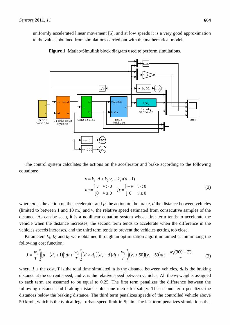
Figure 1 shows the block diagram used for the simulations, in which the following subsystems can
be observed:
- Front vehicle, which provides the speed and distance traveled by the vehicle ahead.
- Ultrasonic system, which measures the distance between vehicles 10 times per second, limited
to between 1 and 10 m due to the limitations of the sensor.
- Controller, which calculates the actions on the accelerator and brake. The output values are
between 0 and 100 as a percentage of total capacity.
- Rear vehicle, which incorporates the aforementioned mathematical model of the vehicle’s
longitudinal dynamics.
- Safety Distance, which calculates the braking distance based on vehicle speed according to
the expression:
g
vdb
··2
2
(1)
with db being the braking distance, v the vehicle speed, µ the friction coefficient between tyres
and road, and g the acceleration of gravity. This expression is derived from the equations of
Sensors 2011, 11
664
uniformly accelerated linear movement [5], and at low speeds it is a very good approximation
to the values obtained from simulations carried out with the mathematical model.
Figure 1. Matlab/Simulink block diagram used to perform simulations.
The control system calculates the actions on the accelerator and brake according to the following
equations:
00
0
00
0
)1/(· 321
v
vvfr
v
vvac
dkvkdkv r
(2)
where ac is the action on the accelerator and fr the action on the brake, d the distance between vehicles
(limited to between 1 and 10 m.) and vr the relative speed estimated from consecutive samples of the
distance. As can be seen, it is a nonlinear equation system whose first term tends to accelerate the
vehicle when the distance increases, the second term tends to accelerate when the difference in the
vehicles speeds increases, and the third term tends to prevent the vehicles getting too close.
Parameters k1, k2 and k3 were obtained through an optimization algorithm aimed at minimizing the
following cost function:
T
Twdtvv
T
wdtdddd
T
wdtdd
T
wJ
T T
rrbb
T
b
)300(50501 4
0 0
32
0
21 (3)
where J is the cost, T is the total time simulated, d is the distance between vehicles, db is the braking
distance at the current speed, and vr is the relative speed between vehicles. All the wi weights assigned
to each term are assumed to be equal to 0.25. The first term penalizes the difference between the
following distance and braking distance plus one metre for safety. The second term penalizes the
distances below the braking distance. The third term penalizes speeds of the controlled vehicle above
50 km/h, which is the typical legal urban speed limit in Spain. The last term penalizes simulations that
Sensors 2011, 11
665
end too soon, which means that the controlled vehicle has not been able to follow the vehicle in front
during the whole simulation. As can be seen, the cost J of a controller is an unknown function of ki.
The cost value depends on the result of a simulation performed with that controller, but not directly on
the parameters, and is neither continuous nor differentiable, so that traditional methods are not suitable
for its optimization. In this work a GA [7] was used for this task, although any other global
optimization method valid for this kind of problems could have been used, as the Simulated Annealing
method. GA’s are a well-known heuristic method for the global optimization of arbitrarily complex
functions with one or more variables, based on the genetic evolution of species. It is therefore
considered unnecessary to describe the details of its implementation in this work. The objective
function of a GA is dependent on the problem, and there is no design methodology, except trial and
error. In this work several cost functions have been tested trying to optimize the distance between
vehicles, subject to the restrictions described, all with similar results, i.e., obtaining very similar
controllers. The proposed function is only one of them. The parameters of the GA are set so that the
execution of the algorithm several times has led in all cases solutions sufficiently close together to be
able to say with some confidence that these solutions are in the vicinity of global optimum. The best
values obtained by the GA for the parameters are k1 = 1.77, k2 = 12.14 and k3 = 15.75, and the final
cost is J = 0.63. Figure 2 shows the results of a 160-s simulation with the controller obtained, during
which the leading vehicle varies its speed randomly between 0 and 60 km/h.
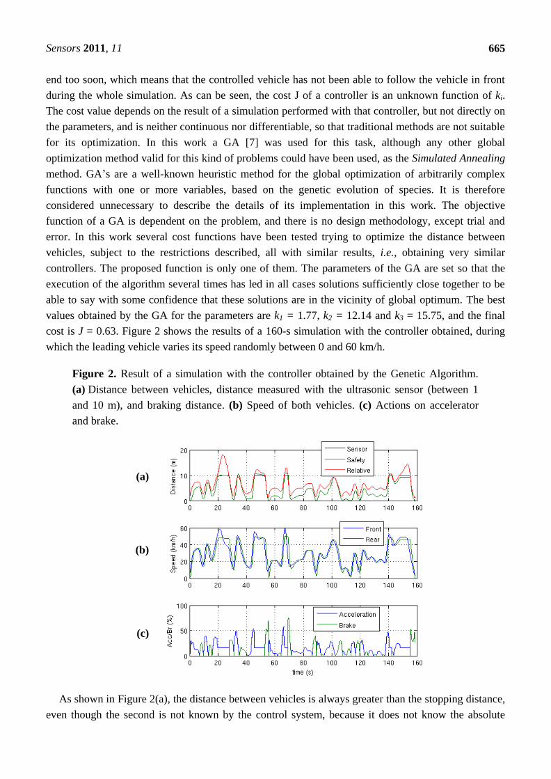
Figure 2. Result of a simulation with the controller obtained by the Genetic Algorithm.
(a) Distance between vehicles, distance measured with the ultrasonic sensor (between 1
and 10 m), and braking distance. (b) Speed of both vehicles. (c) Actions on accelerator
and brake.
(a)
(b)
(c)
As shown in Figure 2(a), the distance between vehicles is always greater than the stopping distance,
even though the second is not known by the control system, because it does not know the absolute
Sensors 2011, 11
666
speed. Figure 2(b) shows that the controlled vehicle never exceeds 50 km/h. even though the vehicle
ahead does so. When the distance between vehicles exceeds 10 m, which is beyond the sensor range,
the controlled vehicle stabilizes its speed at about 50 km/h. In Figure 2(c), the control actions on the
accelerator and brake are shown. At the end of the simulation, it can be seen how the leading vehicle
performs a sudden braking maneuver, and the controlled vehicle stops at a distance of slightly more
than one metre from it without crashing, the brakes remaining at a value around 30% of their capacity.
As a conclusion, we can say that a control system based solely on the distance measured by the
sensor (limited to between 1 and 10 m) is able to adjust the distance, maintaining it greater than the
stopping distance despite not knowing the absolute speed. However, it is necessary to have a
mathematical model of the vehicle that enables the control system to be tuned prior to its experimental
implementation.
3. Ultrasonic System
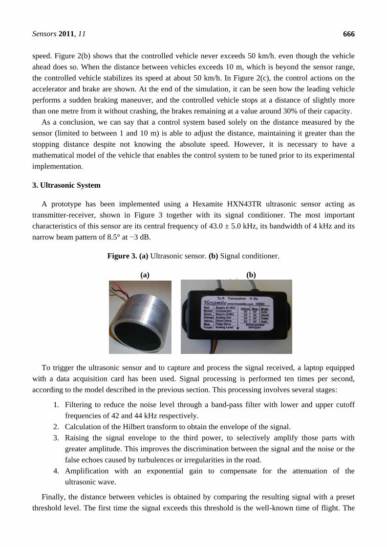
A prototype has been implemented using a Hexamite HXN43TR ultrasonic sensor acting as
transmitter-receiver, shown in Figure 3 together with its signal conditioner. The most important
characteristics of this sensor are its central frequency of 43.0 ± 5.0 kHz, its bandwidth of 4 kHz and its
narrow beam pattern of 8.5° at −3 dB.
Figure 3. (a) Ultrasonic sensor. (b) Signal conditioner.
(a) (b) (a ) (b )
To trigger the ultrasonic sensor and to capture and process the signal received, a laptop equipped
with a data acquisition card has been used. Signal processing is performed ten times per second,
according to the model described in the previous section. This processing involves several stages:
1. Filtering to reduce the noise level through a band-pass filter with lower and upper cutoff
frequencies of 42 and 44 kHz respectively.
2. Calculation of the Hilbert transform to obtain the envelope of the signal.
3. Raising the signal envelope to the third power, to selectively amplify those parts with
greater amplitude. This improves the discrimination between the signal and the noise or the
false echoes caused by turbulences or irregularities in the road.
4. Amplification with an exponential gain to compensate for the attenuation of the
ultrasonic wave.
Finally, the distance between vehicles is obtained by comparing the resulting signal with a preset
threshold level. The first time the signal exceeds this threshold is the well-known time of flight. The
Sensors 2011, 11
667
distance is calculated by multiplying the time of flight by the speed of sound in air, and halving to take
into account that the ultrasonic pulse goes back and forth between the sensor and the vehicle ahead.
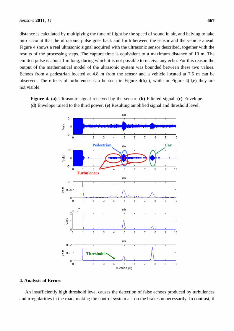
Figure 4 shows a real ultrasonic signal acquired with the ultrasonic sensor described, together with the
results of the processing steps. The capture time is equivalent to a maximum distance of 10 m. The
emitted pulse is about 1 m long, during which it is not possible to receive any echo. For this reason the
output of the mathematical model of the ultrasonic system was bounded between these two values.
Echoes from a pedestrian located at 4.8 m from the sensor and a vehicle located at 7.5 m can be
observed. The effects of turbulences can be seen in Figure 4(b,c), while in Figure 4(d,e) they are
not visible.
Figure 4. (a) Ultrasonic signal received by the sensor. (b) Filtered signal. (c) Envelope.
(d) Envelope raised to the third power. (e) Resulting amplified signal and threshold level.
Pedestrian Car
Turbulences
Threshold
4. Analysis of Errors
An insufficiently high threshold level causes the detection of false echoes produced by turbulences
and irregularities in the road, making the control system act on the brakes unnecessarily. In contrast, if
Sensors 2011, 11
668
the threshold is too high detection failures can occur, meaning that no objects are detected when they
are there and therefore causing possible collisions.
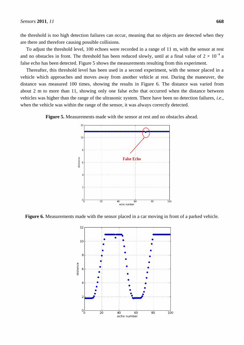
To adjust the threshold level, 100 echoes were recorded in a range of 11 m, with the sensor at rest
and no obstacles in front. The threshold has been reduced slowly, until at a final value of 2 × 10⁻⁴
a
false echo has been detected. Figure 5 shows the measurements resulting from this experiment.
Thereafter, this threshold level has been used in a second experiment, with the sensor placed in a
vehicle which approaches and moves away from another vehicle at rest. During the maneuver, the
distance was measured 100 times, showing the results in Figure 6. The distance was varied from
about 2 m to more than 11, showing only one false echo that occurred when the distance between
vehicles was higher than the range of the ultrasonic system. There have been no detection failures, i.e.,
when the vehicle was within the range of the sensor, it was always correctly detected.
Figure 5. Measurements made with the sensor at rest and no obstacles ahead.
False Echo
Figure 6. Measurements made with the sensor placed in a car moving in front of a parked vehicle.
Sensors 2011, 11
669
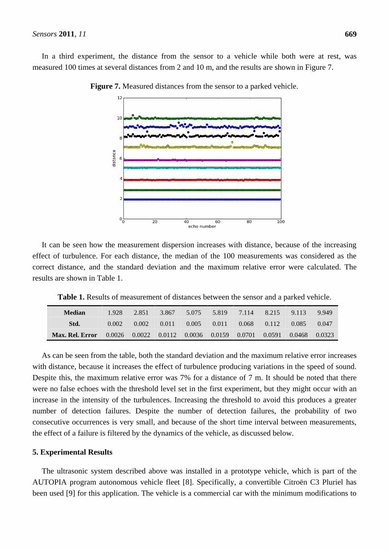
In a third experiment, the distance from the sensor to a vehicle while both were at rest, was
measured 100 times at several distances from 2 and 10 m, and the results are shown in Figure 7.
Figure 7. Measured distances from the sensor to a parked vehicle.
It can be seen how the measurement dispersion increases with distance, because of the increasing
effect of turbulence. For each distance, the median of the 100 measurements was considered as the
correct distance, and the standard deviation and the maximum relative error were calculated. The
results are shown in Table 1.
Table 1. Results of measurement of distances between the sensor and a parked vehicle.
Median 1.928 2.851 3.867 5.075 5.819 7.114 8.215 9.113 9.949
Std. 0.002 0.002 0.011 0.005 0.011 0.068 0.112 0.085 0.047
Max. Rel. Error 0.0026 0.0022 0.0112 0.0036 0.0159 0.0701 0.0591 0.0468 0.0323
As can be seen from the table, both the standard deviation and the maximum relative error increases
with distance, because it increases the effect of turbulence producing variations in the speed of sound.
Despite this, the maximum relative error was 7% for a distance of 7 m. It should be noted that there
were no false echoes with the threshold level set in the first experiment, but they might occur with an
increase in the intensity of the turbulences. Increasing the threshold to avoid this produces a greater
number of detection failures. Despite the number of detection failures, the probability of two
consecutive occurrences is very small, and because of the short time interval between measurements,
the effect of a failure is filtered by the dynamics of the vehicle, as discussed below.
5. Experimental Results
The ultrasonic system described above was installed in a prototype vehicle, which is part of the
AUTOPIA program autonomous vehicle fleet [8]. Specifically, a convertible Citroën C3 Pluriel has
been used [9] for this application. The vehicle is a commercial car with the minimum modifications to
Sensors 2011, 11
670
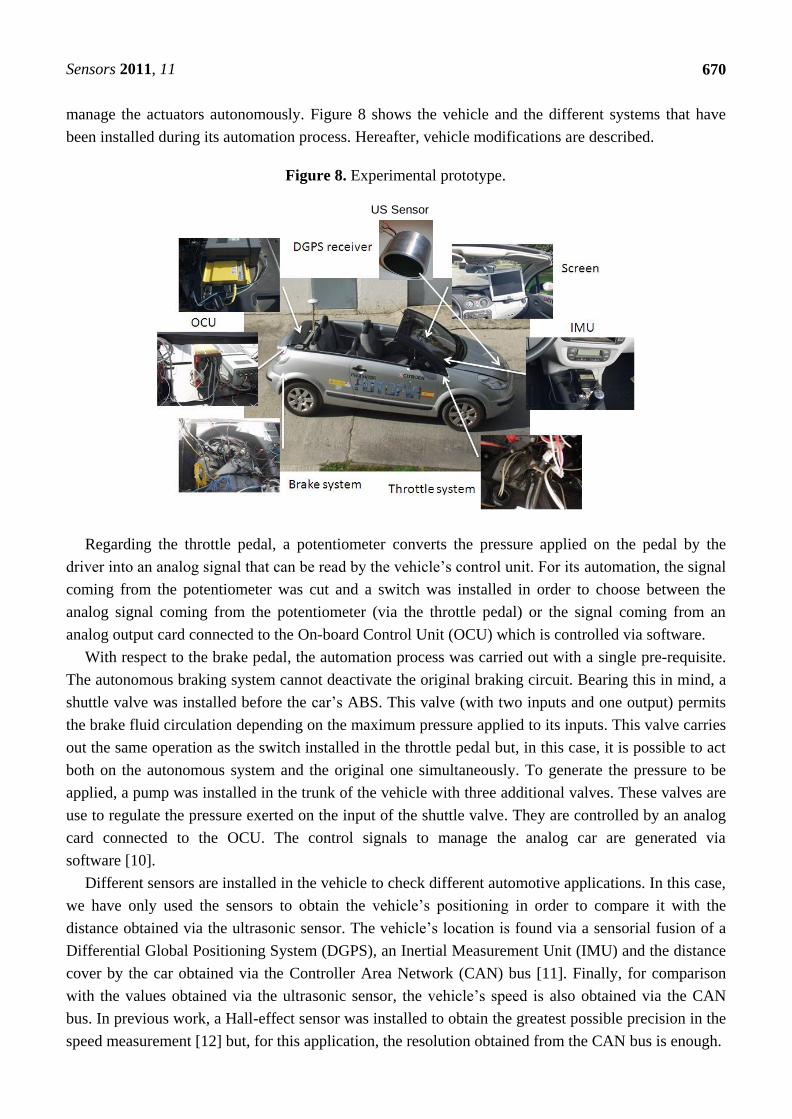
manage the actuators autonomously. Figure 8 shows the vehicle and the different systems that have
been installed during its automation process. Hereafter, vehicle modifications are described.
Figure 8. Experimental prototype.
US Sensor
Regarding the throttle pedal, a potentiometer converts the pressure applied on the pedal by the
driver into an analog signal that can be read by the vehicle’s control unit. For its automation, the signal
coming from the potentiometer was cut and a switch was installed in order to choose between the
analog signal coming from the potentiometer (via the throttle pedal) or the signal coming from an
analog output card connected to the On-board Control Unit (OCU) which is controlled via software.
With respect to the brake pedal, the automation process was carried out with a single pre-requisite.
The autonomous braking system cannot deactivate the original braking circuit. Bearing this in mind, a
shuttle valve was installed before the car’s ABS. This valve (with two inputs and one output) permits
the brake fluid circulation depending on the maximum pressure applied to its inputs. This valve carries
out the same operation as the switch installed in the throttle pedal but, in this case, it is possible to act
both on the autonomous system and the original one simultaneously. To generate the pressure to be
applied, a pump was installed in the trunk of the vehicle with three additional valves. These valves are
use to regulate the pressure exerted on the input of the shuttle valve. They are controlled by an analog
card connected to the OCU. The control signals to manage the analog car are generated via
software [10].
Different sensors are installed in the vehicle to check different automotive applications. In this case,
we have only used the sensors to obtain the vehicle’s positioning in order to compare it with the
distance obtained via the ultrasonic sensor. The vehicle’s location is found via a sensorial fusion of a
Differential Global Positioning System (DGPS), an Inertial Measurement Unit (IMU) and the distance
cover by the car obtained via the Controller Area Network (CAN) bus [11]. Finally, for comparison
with the values obtained via the ultrasonic sensor, the vehicle’s speed is also obtained via the CAN
bus. In previous work, a Hall-effect sensor was installed to obtain the greatest possible precision in the
speed measurement [12] but, for this application, the resolution obtained from the CAN bus is enough.
Sensors 2011, 11
671
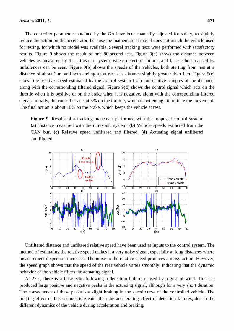
The controller parameters obtained by the GA have been manually adjusted for safety, to slightly
reduce the action on the accelerator, because the mathematical model does not match the vehicle used
for testing, for which no model was available. Several tracking tests were performed with satisfactory
results. Figure 9 shows the result of one 80-second test. Figure 9(a) shows the distance between
vehicles as measured by the ultrasonic system, where detection failures and false echoes caused by
turbulences can be seen. Figure 9(b) shows the speeds of the vehicles, both starting from rest at a
distance of about 3 m, and both ending up at rest at a distance slightly greater than 1 m. Figure 9(c)
shows the relative speed estimated by the control system from consecutive samples of the distance,
along with the corresponding filtered signal. Figure 9(d) shows the control signal which acts on the
throttle when it is positive or on the brake when it is negative, along with the corresponding filtered
signal. Initially, the controller acts at 5% on the throttle, which is not enough to initiate the movement.
The final action is about 10% on the brake, which keeps the vehicle at rest.
Figure 9. Results of a tracking maneuver performed with the proposed control system.
(a) Distance measured with the ultrasonic system. (b) Vehicle speeds extracted from the
CAN bus. (c) Relative speed unfiltered and filtered. (d) Actuating signal unfiltered
and filtered.
Fa u lt
d e t e c t io n
Fa ls e
e c h o
Unfiltered distance and unfiltered relative speed have been used as inputs to the control system. The
method of estimating the relative speed makes it a very noisy signal, especially at long distances where
measurement dispersion increases. The noise in the relative speed produces a noisy action. However,
the speed graph shows that the speed of the rear vehicle varies smoothly, indicating that the dynamic
behavior of the vehicle filters the actuating signal.
At 27 s, there is a false echo following a detection failure, caused by a gust of wind. This has
produced large positive and negative peaks in the actuating signal, although for a very short duration.
The consequence of these peaks is a slight braking in the speed curve of the controlled vehicle. The
braking effect of false echoes is greater than the accelerating effect of detection failures, due to the
different dynamics of the vehicle during acceleration and braking.
Sensors 2011, 11
672
In conclusion, it can be seen how the controlled vehicle adjusts its speed to that of the vehicle
ahead, and how the distance varies depending on the speed.
6. Conclusions
In the present work, a prototype of an ultrasonic ACC for low speeds and short distances typical of
urban traffic, where the systems available on the market do not work, has been designed, built and
experimentally tested. An ultrasonic sensor, cheaper and less demanding of hardware than other types
of sensors currently used, such as those based on radar or computer vision, is used to measure the
distance between vehicles. The relative speed is estimated using consecutive samples of this distance.
These two quantities are used by the control system to calculate the actions on both the accelerator and
the brake, and to adjust the speed in order to maintain the safety distance. As ultrasonic sensors can
detect any kind of obstacle, this system can also prevent collision with pedestrians, or at least reduce
the injuries sustained.
Since the control system does not use the absolute speed to calculate the safety distance as do the
currently existing systems, interaction with automotive electronics is limited to actions on the
accelerator and brake. This fact, coupled with the lower cost of ultrasonic sensors compared with other
kinds of sensors, could facilitate the mounting of the system in low-end vehicles, helping to improve
comfort and safety at a reduced cost.
Acknowledgements
This work is the result of collaboration between the Control Engineering Group of the University of
Cantabria and the team of the AUTOPIA program at the Center for Automation and Robotics (CAR,
UPM-CSIC), and was performed under the auspices of the project CICYT-DPI2007-64295.
References and Notes
1. Observatorio Nacional de Seguridad Vial. Anuario Estadístico de Accidentes 2009; Dirección
General de Tráfico, Ministerio del Interior: Madrid, Spain, 2008.
2. Onieva, E.; Milanés, V.; González, C.; de Pedro, T.; Pérez, J.; Alonso, J. Throttle and brake
pedals automation for populated areas. Robotica 2010, 28, 509-516.
3. Kinsler, L.E.; Frey, A.R.; Coopens A.B.; Sanders, J.V. Fundamentals of Acoustics, 4th ed.; Wiley:
New York, NY, USA, 2000.
4. Alonso, L. Contribuciones al estudio de sistemas ultrasónicos y su aplicación a la seguridad
activa en vehículos inteligentes. Ph.D. Thesis, University of Cantabria, Cantabria, Spain, 2009.
5. Alonso, L.; Pérez-Oria, J.M.; Fernández, M.; Rodríguez, C.; Arce, J.; Ibarra, M.; Ordoñez, V.
Genetically tuned controller of an adaptive cruise control for urban traffic based on ultrasounds.
In Artificial Neural Networks—ICANN 2010; Lecture Notes on Computer Science; Springer:
Berlin/Heidelberg, Germany, 2010; Volume 6353/2010, pp. 479-485.
6. Short, M.; Pont, M.J.; Huang, Q. Simulation of Vehicle Longitudinal Dynamics; Embedded
Systems Laboratory, University of Leicester: Leicester, UK, 2004.
Sensors 2011, 11
673
7. Holland, J.H. Adaptation in Natural and Artificial Systems; MIT Press: Cambridge, MA, USA,
1992.
8. Autopia. Available online: http://www.iai.csic.es/users/autopia/programa_en.html (accessed on
September 15, 2010).
9. Milanés, V.; Llorca, D.F.; Vinagre, B.; González, C.; Sotelo, M.A. Clavileño: Evolution of an
Autonomous Car. In Proceedings of 13th International IEEE Conference on Intelligent
Transportation Systems, Funchal, Portugal, September 20–22, 2010.
10. Milanés, V.; González, C.; Naranjo, J.; Onieva, E.; de Pedro, T. Electro-Hydraulic Braking
System for Autonomous Vehicles. Int. J. Autom. Technol. 2010, 11, 89-95.
11. Milanés, V.; Naranjo, J.; González, C.; Alonso, J.; de Pedro, T. Autonomous vehicle based in
cooperative GPS and intertial systems. Robotica 2008, 26, 627-633.
12. Pérez, J.; Seco, F.; Milanés, V.; Jiménez, A.; Díaz, J.C.; de Pedro, T. An RFID-based intelligent
vehicle speed controller using active traffic signals. Sensors 2010, 10, 5872-5887.
© 2011 by the authors; licensee MDPI, Basel, Switzerland. This article is an open access article
distributed under the terms and conditions of the Creative Commons Attribution license
(http://creativecommons.org/licenses/by/3.0/).