ultrasonic flowmeters for liquids for permanent ... · calculation of volumetric flow rate ......
TRANSCRIPT

Technical Specification
FLUXUS® F808/809
TSFLUXUS_F808_809V1-7EN_Leu, 2015-10-14 1
Transmitter FLUXUS F808
Transmitter FLUXUS F809
Measurement with transducers mounted by Variofix C
Measurement with transducers mounted by PermaFiX
Ultrasonic Flowmeters for Liquids for Permanent Installation in Hazardous Areas
Especially designed for the stationary use in explosive atmosphere
Features
• F808: instrument with one measuring channel for exact and reliable flow measurement
• F809: Instrument with two measuring channels for exact and reliable flow measurement under complex flow conditions
• Precise bi-directional and highly dynamic flow measurement with the non-intrusive clamp-on technology
• High precision at fast and slow flow rates, high temperature and zero point stability
• Transmitter housing:- Corrosionproof and suitable for offshore application- Transmitter F80x**-A1 in a flameproof housing (degree of
protection IP66)- Transmitter F80x**-F1 in an explosionproof housing (NEMA
4X)
• Certifications:- F80x**-A1: ATEX/IECEx- F80x**-F1: FM Cl. 1, Div. 1- F808**-F2: FM Cl. 1, Div. 2
• The transmitters can be operated by a magnet pen without opening the housing
• Automatic loading of calibration data and transducer detection for a fast and easy set-up (less than 5 min), providing precise and long-term stable results
• User-friendly design
• Communication interfaces Modbus RTU and HART available
• Transducers available for a wide range of inner pipe diame-ters ( ) and fluid temperatures ( )
• Flow measurement independent of pipe wall thickness and medium pressure
• approved transducers for hazardous areas available
• HybridTrek automatically switches between transit time and NoiseTrek mode of measurement when high particulate flows are encountered
• Measurement is unaffected by medium density, viscosity and solid content (max. 10 % of volume)
• Product variant FLUXUS XLF is especially suited for precise and reliable flow measurement applications with very low flow velocities (e.g. chemical injection in oil and gas extraction)
Applications
Designed for industrial use in harsh environments, especially for oil extraction and processing in the petrochemical and chemical industry.• Chemical industry• Petrochemical industry• Oil extraction and exploration• Refineries
6...6500 mm -170...+600 °C
ATEX/IECEx, FM Class 1 Div. 1/Div.2

FLUXUS® F808/809 Technical Specification
Table of Contents
TSFLUXUS_F808_809V1-7EN_Leu, 2015-10-142
Function ........................................................................................................................................................... 3Measurement Principle ..................................................................................................................................... 3Calculation of Volumetric Flow Rate ................................................................................................................. 3Number of Sound Paths.................................................................................................................................... 4Typical Measurement Setup ............................................................................................................................. 4
Flow Transmitter ............................................................................................................................................. 5Technical Data .................................................................................................................................................. 5Dimensions ....................................................................................................................................................... 8Wall and 2 " Pipe Mounting Kit........................................................................................................................ 10Terminal Assignment ...................................................................................................................................... 11
Transducers................................................................................................................................................... 13Transducer Selection ...................................................................................................................................... 13Transducer Order Code .................................................................................................................................. 14Technical Data ................................................................................................................................................ 15
Transducer Mounting Fixture ...................................................................................................................... 25
Coupling Materials for Transducers............................................................................................................ 28
Connection Systems..................................................................................................................................... 29Transducer Cable............................................................................................................................................ 30
Junction Box (F80***-A1) .............................................................................................................................. 31Technical Data ................................................................................................................................................ 31Dimensions ..................................................................................................................................................... 312 " Pipe Mounting Kit (optional)....................................................................................................................... 32Terminal Assignment ...................................................................................................................................... 32
Extension Cable (F80***-F1) ......................................................................................................................... 33Terminal Assignment for Terminal Board KFM1 ............................................................................................. 33

TSFLUXUS_F808_809V1-7EN_Leu, 2015-10-14 3
Technical Specification FLUXUS® F808/809
Function
Measurement Principle
Transit Time Difference Principle
In order to measure the flow of a medium in a pipe, ultrasonic signals are used, employing the transit time dif-ference principle. Ultrasonic signals are emitted by a transducer installed on the pipe and received by a sec-ond transducer. These signals are emitted alternately in the flow direction and against it.
As the medium in which the signals propagate is flowing, the transit time of the ultrasonic signals in the flowdirection is shorter than against the flow direction.
The transit time difference, ∆t, is measured and allows the flowmeter to determine the average flow velocityalong the propagation path of the ultrasonic signals. A flow profile correction is then performed in order to ob-tain the area averaged flow velocity, which is proportional to the volumetric flow rate.
Two integrated microprocessors control the entire measuring process. This allows the flowmeter to removedisturbance signals, and to check each received ultrasonic wave for its validity which reduces noise.
HybridTrek
If the gaseous or solid content in the medium increases occasionally during measurement, a measurementwith the transit time difference principle is no longer possible. NoiseTrek mode will then be selected by theflowmeter. This measurement method allows the flowmeter to achieve a stable measurement even with highgaseous or solid content.
The transmitter can switch automatically between transit time and NoiseTrek mode without any changes tothe measurement setup.
Calculation of Volumetric Flow Rate
= kRe . A . ka . ∆t/(2 . tfl)
where
Path of the ultrasonic signal Transit time difference ∆t
- volumetric flow ratekRe - fluid mechanics calibration factorA - cross-sectional pipe areaka - acoustical calibration factor∆t - transit time differencetfl - transit time in the medium
V·
V·

4 TSFLUXUS_F808_809V1-7EN_Leu, 2015-10-14
FLUXUS® F808/809 Technical Specification
Number of Sound Paths
The number of sound paths is the number of transits of the ultrasonic signal through the medium in the pipe.Depending on the number of sound paths, the following methods of installation exist:
• reflection arrangementThe number of sound paths is even. Both of the transducers are mounted on the same side of the pipe. Correct positioning of the transducers is easier.
• diagonal arrangementThe number of sound paths is odd. Both of the transducers are mounted on opposite sides of the pipe. In the case of a high signal attenuation by the medium, pipe and coatings, diagonal arrangement with 1 sound path will be used.
The preferred method of installation depends on the application. While increasing the number of sound pathsincreases the accuracy of the measurement, signal attenuation increases as well. The optimum number ofsound paths for the parameters of the application will be determined automatically by the transmitter.
As the transducers can be mounted with the transducer mounting fixture in reflection arrangement or diagonalarrangement, the number of sound paths can be adjusted optimally for the application..
Typical Measurement Setup
a - transducer distance
Reflection arrangement, number of sound paths: 2
Diagonal arrangement, number of sound paths: 3
Diagonal arrangement, number of sound paths: 1 Diagonal arrangement, number of sound paths: 1,negative transducer distance
Example of a measurement setup in reflection arrangement
a
a
a > 0 a < 0
transducers
transmitter
outputs
power supply
RS485(optional)

TSFLUXUS_F808_809V1-7EN_Leu, 2015-10-14 5
Technical Specification FLUXUS® F808/809
Flow Transmitter
Technical Data
FLUXUS F809**-A1F809**-A1A
F809**-F1 F808**-A1 F808**-F1 F808**-F2
design explosion proof field device, 1 or 2 mea-suring channels
explosion proof field device, 1 measuring channel
transducers C****81, C****LI1, C***2E85
C**1N62 C****81, C****LI1, C***2E85
C**1N62 C****53
measurementmeasurement principle transit time difference correlation principle,
automatic NoiseTrek selection for measurements with high gaseous or solid contentflow velocity 0.01...25 m/srepeatability 0.15 % of reading ±0.01 m/smedium all acoustically conductive liquids with < 10 % gaseous or solid content in volume (transit time difference
principle)temperature compensation corresponding to the recommendations in ANSI/ASME MFC-5.1-2011accuracy1
with standard calibrationwith advanced calibration (optional)with field calibration2 ±0.5 % of reading ±0.01 m/sflow transmitterpower supply 100...240 V/50...60 Hz
or20...32 V DC
power consumption < 8 Wnumber of flow measuring channels
1, optional: 2 1
damping 0...100 s, adjustablemeasuring cycle (1 channel) 100...1000 Hzresponse time 1 s, option: 70 mshousing material cast aluminum, special offshore coatingdegree of protection accord-ing to IEC/EN 60529
IP66
dimensions see dimensional drawingweight 6.1 kg 5.3 kgfixation wall mounting, 2 " pipe mountingoperating temperature -30...+60 °C (< -20 °C without operation of the display)display 2 x 16 characters, dot matrix, backlightmenu language English, German, French, Dutch, Spanish
1 for transit time difference principle, reference conditions and v > 0.15 m/s2 reference uncertainty < 0.2 %
±1.6 % of reading ±0.01 m/s±1.2 % of reading ±0.01 m/s

6 TSFLUXUS_F808_809V1-7EN_Leu, 2015-10-14
FLUXUS® F808/809 Technical Specification
explosion protection
ATEX/IECEx
zone 1marking F809**-A1
Ex db e IIC T6 GbEx tb IIIC T 100 °C DbTa -40...+60 °C
F809**-A1A
Ex db e ia IIC T6 GbEx tb ia IIIC T 100 °C DbTa -40...+60 °C
-
Ex db e IIC T6 GbEx tb IIIC T 100 °C DbTa -40...+60 °C
- -
certification ATEX IBExU11ATEX1022 X
- IBExU11ATEX1022 X
- -
certification IECEx IECEx IBE 11.0006X
- IECEx IBE 11.0006X
- -
type of protection gas: electronics compartment: flameproof enclo-sure, connection compartment: increased safetydust: protection by enclosure
- gas: electronics compartment: flameproof enclo-sure, connection compartment: increased safetydust: protection by enclosure
- -
intrinsic safety parameters F809**-A1AUm = 250 VUi = 30 V DCIi = 56 mAPi = 0.42 WCi = 3 nF
- - - -
FM
marking -
Cl. I, II, III/Div. 1/GP. A, B, C, D, E, F, G/For Group A, con-duit seal of connec-tion compartment is required within 18 inches.
Cl. I, II, III/Div. 1/GP. B, C, D, E, F, G
T4A Ta = 60 °C
-
Cl. I, II, III/Div. 1/GP. A, B, C, D, E, F, G/For Group A, con-duit seal of connec-tion compartment is required within 18 inches.
Cl. I, II, III/Div. 1/GP. B, C, D, E, F, G
T5 Ta = 60 °C
Cl. I, II, III/Div. 2/GP. A, B, C, D, E, F, G/T5 Ta = 60 °C
measuring functionsphysical quantities volumetric flow rate, mass flow rate, flow velocitytotalizer volume, masscalculation functions average, difference, sum (2 measuring
channels necessary)-
diagnostic functions sound speed, signal amplitude, SNR, SCNR, standard deviation of amplitudes and transit timesdata loggerloggable values all physical quantities, totalized values and diagnostic valuescapacity > 100 000 measured valuescommunicationinterface - process integration (optional): Modbus RTU or HART
- diagnosis: RS2323
3 connection of the interface RS232 outside of explosive atmosphere (housing cover open)
FLUXUS F809**-A1F809**-A1A
F809**-F1 F808**-A1 F808**-F1 F808**-F2
II2GII2D
0637
II2GII2D
0637
II2GII2D
0637

TSFLUXUS_F808_809V1-7EN_Leu, 2015-10-14 7
Technical Specification FLUXUS® F808/809
serial data kit (optional)software (all Windows™ versions)
- FluxData: download of measurement data, graphical presentation,conversion to other formats (e.g. for Excel™)
- FluxDiag (optional): online diagnostics and report generation
- FluxKoef: creating medium data sets
- FluxSubstanceLoader: upload of medium data setsсable RS2323
adapter RS232 - USB3
outputsThe outputs are galvanically isolated from the transmitter.
number F809**-A1current output: 2binary output: 2 or 4
or
current output: 0 or 1binary output: 1Modbus
or
current output: 2/HARTbinary output: 2
or
frequency output: 1binary output: 1
F809**-A1Acurrent output (intrinsic safety): 1/HART
current output: 2binary output: 2 or 4
or
current output: 0 or 1binary output: 1Modbus
or
current output: 2/HARTbinary output: 2
or
frequency output: 1binary output: 1
current output: 1binary output: 1
or
current output: 1Modbus
or
current output: 1/HARTbinary output: 1
current outputcurrent output I1, I2- range 0/4...20 mA- accuracy 0.1 % of reading ±15 μA- active output Rext < 500 Ω- passive output Uext = 4...26.4 V, depending on Rext, Rext < 1 kΩcurrent output I1 in HART mode- range 4...20 mA- passive output Uext = 7...30 V DC- active output Uint = 24 V
current output (intrinsic safety)current output I1- range 4...20 mA - -- accuracy 0.04 % of reading
±3 μA- -
- passive output Uext = 7...30 V, depending on Rext, Rext < 1 kΩ
- -
current output I1 in HART mode- range 4...20 mA -- passive output Uext = 7...30 V DC -
frequency outputrange 0...5 kHz -open collector 24 V/4 mA
optional: 30 V/100 mA or8.2 V DIN EN 60947-5-6 (NAMUR)
-
binary outputReed relay 48 V/100 mA -open collector 24 V/4 mA
optional: 30 V/100 mA or8.2 V DIN EN 60947-5-6 (NAMUR)
24 V/4 mA
optional (only in combination with HART): 30 V/100 mA or8.2 V DIN EN 60947-5-6 (NAMUR)
binary output as alarm output- functions limit, change of flow direction or errorbinary output as pulse output- pulse value 0.01...1000 units- pulse width 80...1000 ms
3 connection of the interface RS232 outside of explosive atmosphere (housing cover open)
FLUXUS F809**-A1F809**-A1A
F809**-F1 F808**-A1 F808**-F1 F808**-F2

8 TSFLUXUS_F808_809V1-7EN_Leu, 2015-10-14
FLUXUS® F808/809 Technical Specification
Dimensions
FLUXUS F808**-A1, F808**-F2
FLUXUS F808**-F1
243
174
thread, cable gland: 4x M20 x 1.5
136
286
material: stainless steel 304 (1.4301)
243
174
thread: 4x NPT 3/4
136
286
material: stainless steel 304 (1.4301)
TSFLUXUS_F808_809V1-7EN_Leu, 2015-10-14 9
Technical Specification FLUXUS® F808/809
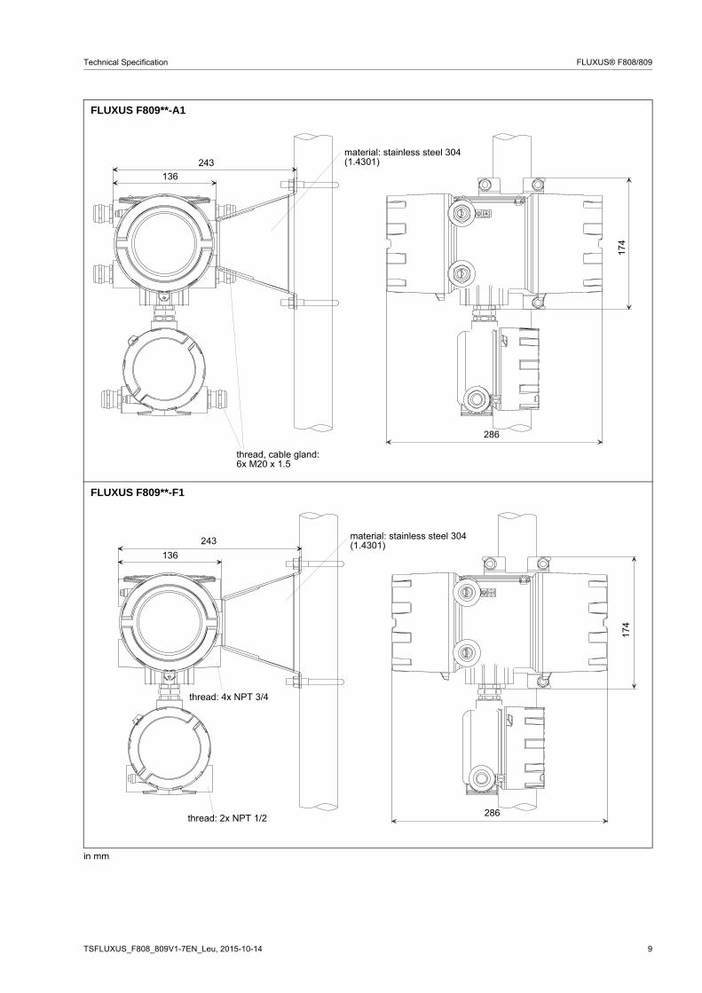
FLUXUS F809**-A1
FLUXUS F809**-F1
in mm
243
174
thread, cable gland:6x M20 x 1.5
136
286
material: stainless steel 304 (1.4301)
243
174
thread: 4x NPT 3/4
136
286
material: stainless steel 304 (1.4301)
thread: 2x NPT 1/2
10 TSFLUXUS_F808_809V1-7EN_Leu, 2015-10-14
FLUXUS® F808/809 Technical Specification
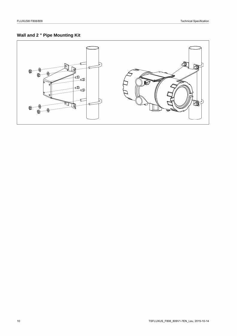
Wall and 2 " Pipe Mounting Kit

TSFLUXUS_F808_809V1-7EN_Leu, 2015-10-14 11
Technical Specification FLUXUS® F808/809
Terminal Assignment
power supply
transducers
outputs (Options)
FLUXUS F808
AC DCterminal strip terminal connection terminal connectionKL2 L phase L+ +
N neutral L- -PE earth PE earth
measuring channel Aterminal strip terminal connectionKL4 ARS transducer , internal shield
AR transducer , signalAV transducer , signalAVS transducer , internal shield
cable gland or equipotential bonding terminal (transducers)
external shield
terminal strip terminal connectionKL1 4 GND 6 (+) 5 (-) binary output B1KL3 3 GND 2 (+) 1 (-) active current output I1
terminal strip terminal connectionKL1 4 GND 6 (+) 5 (-) binary output B1KL3 3 GND 1 (-) 2 (+) passive current output I1
terminal strip terminal connectionKL1 1 (S) 2 (A+) 3 (B-) ModbusKL3 3 GND 2 (+) 1 (-) active current output I1
terminal strip terminal connectionKL1 1 (S) 2 (A+) 3 (B-) ModbusKL3 3 GND 1 (-) 2 (+) passive current output I1
KL2
KL1
KL4
KL3
equipotential bonding terminal
equipotential bonding terminal (transducers)
power supply
transducers
outputs
12 TSFLUXUS_F808_809V1-7EN_Leu, 2015-10-14
FLUXUS® F808/809 Technical Specification
power supply
transducers
outputs
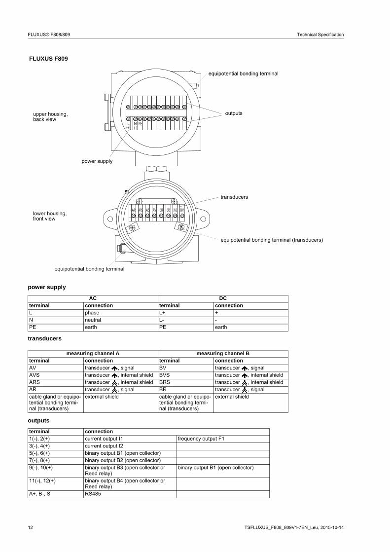
FLUXUS F809
AC DCterminal connection terminal connectionL phase L+ +N neutral L- -PE earth PE earth
measuring channel A measuring channel Bterminal connection terminal connectionAV transducer , signal BV transducer , signalAVS transducer , internal shield BVS transducer , internal shieldARS transducer , internal shield BRS transducer , internal shieldAR transducer , signal BR transducer , signalcable gland or equipo-tential bonding termi-nal (transducers)
external shield cable gland or equipo-tential bonding termi-nal (transducers)
external shield
terminal connection1(-), 2(+) current output I1 frequency output F13(-), 4(+) current output I25(-), 6(+) binary output B1 (open collector)7(-), 8(+) binary output B2 (open collector)9(-), 10(+) binary output B3 (open collector or
Reed relay)binary output B1 (open collector)
11(-), 12(+) binary output B4 (open collector or Reed relay)
A+, B-, S RS485
L N PE(+) (-)
AR ARS AVAVS BR BRS BVBVS
equipotential bonding terminal
lower housing,front view
upper housing,back view
equipotential bonding terminal
power supply
transducers
outputs
equipotential bonding terminal (transducers)
TSFLUXUS_F808_809V1-7EN_Leu, 2015-10-14 13
Technical Specification FLUXUS® F808/809
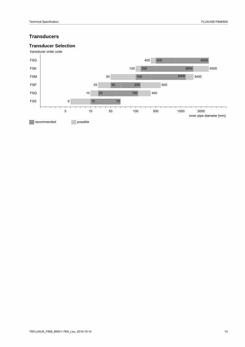
Transducers
Transducer Selectiontransducer order code
FSG 400 500 6500
FSK 100 200 3600 6500
FSM 50 100 2000 3400
FSP 25 50 200 600
FSQ 10 25 150 400
FSS 6 10 70
5 10 50 100 500 1000 5000inner pipe diameter [mm]
recommended possible

14 TSFLUXUS_F808_809V1-7EN_Leu, 2015-10-14
FLUXUS® F808/809 Technical Specification
Transducer Order Code
1, 2 3 4 5, 6 7, 8 9...11 12, 13 no. of character
tra
nsdu
cer
tra
nsdu
cer
fre
quen
cy
- ambi
ent
tem
pera
ture
expl
osio
n pr
ote
ctio
n
conn
ectio
n sy
stem
- exte
nsio
n ca
ble
/ optio
n
description
FS set of ultrasonic flow transducers for liquids measurement, shear wave
G 0.2 MHz
K 0.5 MHz
M 1 MHz
P 2 MHz
Q 4 MHz
S 8 MHz
N normal temperature range
E extended temperature range (shear wave transducers with trans-ducer frequency M, P, Q)
A1 ATEX zone 1/IECEx zone 1
F1 FM Class I Div. 1
F2 FM Class I Div. 2
TS direct connection or connection via junction box
TI direct connection
XXX 0 m: without extension cable
> 0 m: with extension cable, F80***-A1: with junction box, F80***-F1: with terminal board KFM1
LC long transducer cable
IP68 degree of protection IP68
OS housing with stainless steel 316
example
FS M - N A1 TS - 000 shear wave transducer 1 MHz, normal temperature range, ATEX zone 1/IECEx zone 1, connection system TS (direct connection)
- - /

TSFLUXUS_F808_809V1-7EN_Leu, 2015-10-14 15
Technical Specification FLUXUS® F808/809
Technical Data
Shear Wave Transducers (zone 1)
technical type CDG1N81 CDK1N81order code FSG-NA1TS
FSG-NA1TS/OSFSK-NA1TSFSK-NA1TS/OS
transducer frequency MHz 0.2 0.5
inner pipe diameter dmin. extended mm 400 100min. recommended mm 500 200max. recommended mm 6500 3600max. extended mm 6500 6500pipe wall thicknessmin. mm - -max. mm - -materialhousing PEEK with stainless steel
cap 304 (1.4301), option OS: 316L (1.4404)
PEEK with stainless steel cap 304 (1.4301), option OS: 316L (1.4404)
contact surface PEEK PEEKdegree of protection according to IEC/EN 60529
IP65 IP66
transducer cabletype 1699 1699length m 5 5dimensionslength l mm 129.5 126.5width b mm 51 51height h mm 67 67.5dimensional drawing
ambient temperaturemin. °C -40 -40max. °C +130 +130temperature compensation
x x
explosion protection
ATEX/IECEx
categoryzone
gas: 2G dust: 2D1 21
gas: 2G dust: 2D1 21
explosion protection temperature (pipe surface)min. °C -55 -55max. °C +180 +180marking
Ex e q IIC T6...T3 GbEx tb IIIC TX Db
Ex e q IIC T6...T3 GbEx tb IIIC TX Db
certification ATEX IBExU07ATEX1168 X IBExU07ATEX1168 Xcertification IECEx IECEx IBE 08.0007X IECEx IBE 08.0007Xtype of protection gas: increased safety,
powder fillingdust: protection by enclosure
gas: increased safety, powder fillingdust: protection by enclosure
transducer mounting fixture necessary
x x
remark on request
l
hb
l
hb
II2GII2D
0637 II2GII2D
0637

16 TSFLUXUS_F808_809V1-7EN_Leu, 2015-10-14
FLUXUS® F808/809 Technical Specification
technical type CDM2N81 CDP2N81 CDQ2N81order code FSM-NA1TS
FSM-NA1TS/OSFSP-NA1TSFSP-NA1TS/OS
FSQ-NA1TSFSQ-NA1TS/OS
transducer frequency MHz 1 2 4
inner pipe diameter dmin. extended mm 50 25 10min. recommended mm 100 50 25max. recommended mm 2000 200 150max. extended mm 3400 600 400pipe wall thicknessmin. mm - - -max. mm - - -materialhousing PEEK with stainless steel
cap 304 (1.4301), option OS: 316L (1.4404)
PEEK with stainless steel cap 304 (1.4301), option OS: 316L (1.4404)
PEEK with stainless steel cap 304 (1.4301), option OS: 316L (1.4404)
contact surface PEEK PEEK PEEKdegree of protection according to IEC/EN 60529
IP66 IP66 IP65
transducer cabletype 1699 1699 1699length m 4 4 3dimensionslength l mm 64 64 40width b mm 32 32 22height h mm 40.5 40.5 25.5dimensional drawing
ambient temperaturemin. °C -40 -40 -40max. °C +130 +130 +130temperature compensation
x x x
explosion protection
ATEX/IECEx
categoryzone
gas: 2G dust: 2D1 21
gas: 2G dust: 2D1 21
gas: 2G dust: 2D1 21
explosion protection temperature (pipe surface)min. °C -55 -55 -55max. °C +180 +180 +180marking
Ex e q IIC T6...T3 GbEx tb IIIC TX Db
Ex e q IIC T6...T3 GbEx tb IIIC TX Db
Ex e q IIC T6...T3 GbEx tb IIIC TX Db
certification ATEX IBExU07ATEX1168 X IBExU07ATEX1168 X IBExU07ATEX1168 Xcertification IECEx IECEx IBE 08.0007X IECEx IBE 08.0007X IECEx IBE 08.0007Xtype of protection gas: increased safety,
powder fillingdust: protection by enclosure
gas: increased safety, powder fillingdust: protection by enclosure
gas: increased safety, powder fillingdust: protection by enclosure
transducer mounting fixture necessary
x x x
l
hb
l
hb
hb
l
II2GII2D
0637 II2GII2D
0637 II2GII2D
0637
TSFLUXUS_F808_809V1-7EN_Leu, 2015-10-14 17
Technical Specification FLUXUS® F808/809
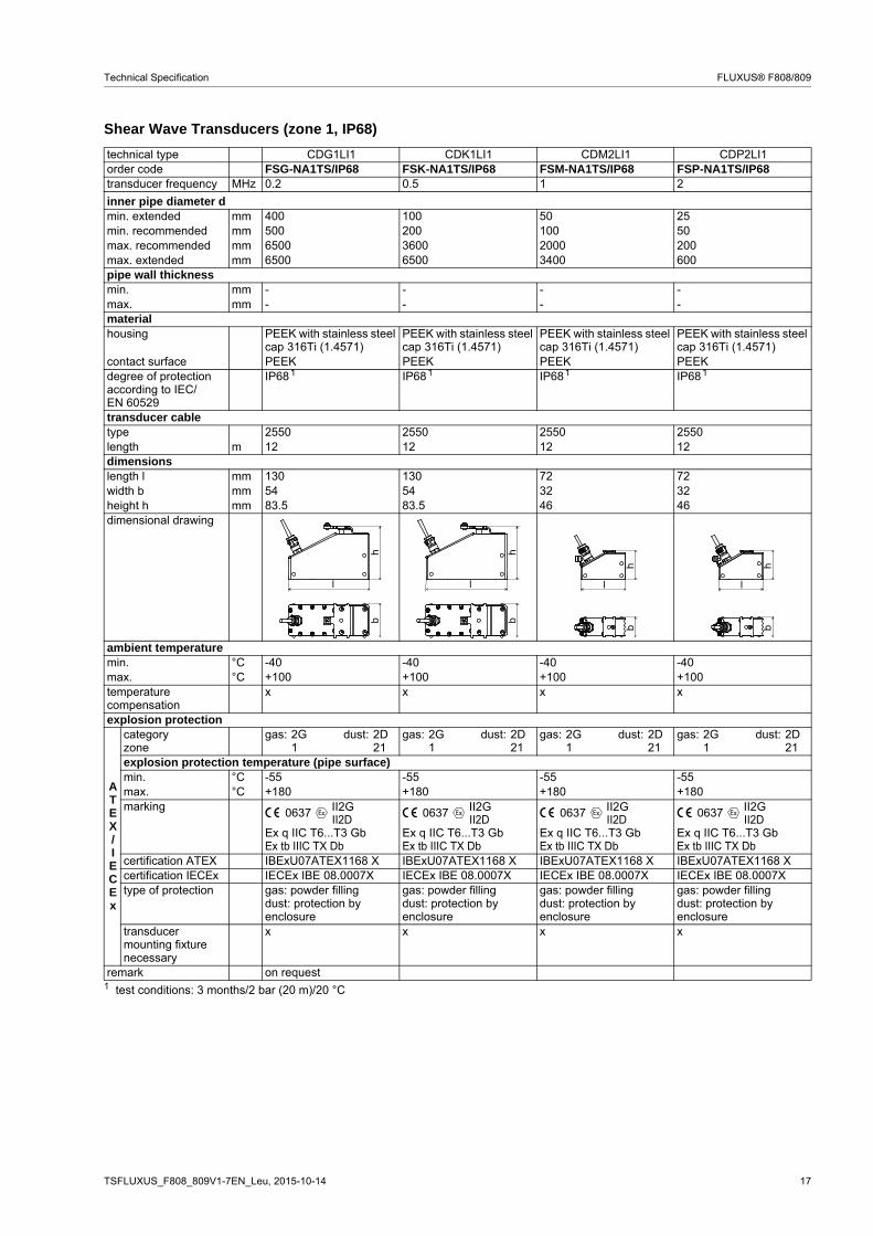
Shear Wave Transducers (zone 1, IP68)
technical type CDG1LI1 CDK1LI1 CDM2LI1 CDP2LI1order code FSG-NA1TS/IP68 FSK-NA1TS/IP68 FSM-NA1TS/IP68 FSP-NA1TS/IP68transducer frequency MHz 0.2 0.5 1 2
inner pipe diameter dmin. extended mm 400 100 50 25min. recommended mm 500 200 100 50max. recommended mm 6500 3600 2000 200max. extended mm 6500 6500 3400 600pipe wall thicknessmin. mm - - - -max. mm - - - -materialhousing PEEK with stainless steel
cap 316Ti (1.4571)PEEK with stainless steel cap 316Ti (1.4571)
PEEK with stainless steel cap 316Ti (1.4571)
PEEK with stainless steel cap 316Ti (1.4571)
contact surface PEEK PEEK PEEK PEEKdegree of protection according to IEC/EN 60529
IP68 IP68 IP68 IP68
transducer cabletype 2550 2550 2550 2550length m 12 12 12 12dimensionslength l mm 130 130 72 72width b mm 54 54 32 32height h mm 83.5 83.5 46 46dimensional drawing
ambient temperaturemin. °C -40 -40 -40 -40max. °C +100 +100 +100 +100temperature compensation
x x x x
explosion protection
ATEX/IECEx
categoryzone
gas: 2G dust: 2D1 21
gas: 2G dust: 2D1 21
gas: 2G dust: 2D1 21
gas: 2G dust: 2D1 21
explosion protection temperature (pipe surface)min. °C -55 -55 -55 -55max. °C +180 +180 +180 +180marking
Ex q IIC T6...T3 GbEx tb IIIC TX Db
Ex q IIC T6...T3 GbEx tb IIIC TX Db
Ex q IIC T6...T3 GbEx tb IIIC TX Db
Ex q IIC T6...T3 GbEx tb IIIC TX Db
certification ATEX IBExU07ATEX1168 X IBExU07ATEX1168 X IBExU07ATEX1168 X IBExU07ATEX1168 Xcertification IECEx IECEx IBE 08.0007X IECEx IBE 08.0007X IECEx IBE 08.0007X IECEx IBE 08.0007Xtype of protection gas: powder filling
dust: protection by enclosure
gas: powder fillingdust: protection by enclosure
gas: powder fillingdust: protection by enclosure
gas: powder fillingdust: protection by enclosure
transducer mounting fixture necessary
x x x x
remark on request1 test conditions: 3 months/2 bar (20 m)/20 °C
1 1 1 1
l
hb
l
hb
l
hb
l
hb
II2GII2D
0637 II2GII2D
0637 II2GII2D
0637 II2GII2D
0637

18 TSFLUXUS_F808_809V1-7EN_Leu, 2015-10-14
FLUXUS® F808/809 Technical Specification
Shear Wave Transducers (zone 1, extended temperature range)
technical type CDM2E85 CDP2E85 CDQ2E85order code FSM-EA1TS
FSM-EA1TS/OSFSP-EA1TSFSP-EA1TS/OS
FSQ-EA1TSFSQ-EA1TS/OS
transducer frequency MHz 1 2 4
inner pipe diameter dmin. extended mm 50 25 10min. recommended mm 100 50 25max. recommended mm 2000 200 150max. extended mm 3400 600 400pipe wall thicknessmin. mm - - -max. mm - - -materialhousing PI with stainless steel
cap 304 (1.4301), option OS: 316L (1.4404)
PI with stainless steel cap 304 (1.4301), option OS: 316L (1.4404)
PI with stainless steel cap 304 (1.4301), option OS: 316L (1.4404)
contact surface PI PI PIdegree of protection according to IEC/EN 60529
IP66 IP66 IP56
transducer cabletype 6111 6111 6111length m 4 4 3dimensionslength l mm 64 64 40width b mm 32 32 22height h mm 40.5 40.5 25.5dimensional drawing
ambient temperaturemin. °C -30 -30 -30max. °C +200 +200 +200temperature compensation
x x x
explosion protection
ATEX/IECEx
categoryzone
gas: 2G dust: 3D1 22
gas: 2G dust: 3D1 22
gas: 2G dust: 3D1 22
explosion protection temperature (pipe surface)min. °C -45 -45 -45max. °C +225 +225 +225marking
Ex e q IIC T6...T2 GbEx tb IIIA TX Db
Ex e q IIC T6...T2 GbEx tb IIIA TX Db
Ex e q IIC T6...T2 GbEx tb IIIA TX Db
certification ATEX IBExU07ATEX1168 X IBExU07ATEX1168 X IBExU07ATEX1168 Xcertification IECEx IECEx IBE 08.0007X IECEx IBE 08.0007X IECEx IBE 08.0007Xtype of protection gas: increased safety,
powder fillingdust: protection by enclosure
gas: increased safety, powder fillingdust: protection by enclosure
gas: increased safety, powder fillingdust: protection by enclosure
transducer mounting fixture necessary
x x x
l
hb
l
hb
hb
l
II2GII2D
0637 II2GII2D
0637 II2GII2D
0637

TSFLUXUS_F808_809V1-7EN_Leu, 2015-10-14 19
Technical Specification FLUXUS® F808/809
Shear Wave Transducers (FM Class I, Div. 1)
technical type CDG1N62 CLG1N62 CDK1N62 CLK1N62order code FSG-NF1TS
FSG-NF1TS/OSFSG-NF1TS/LCFSG-NF1TS/OS/LC
FSK-NF1TSFSK-NF1TS/OS
FSK-NF1TS/LCFSK-NF1TS/OS/LC
transducer frequency MHz 0.2 0.5
inner pipe diameter dmin. extended mm 400 100min. recommended mm 500 200max. recommended mm 6500 3600max. extended mm 6500 6500pipe wall thicknessmin. mm - -max. mm - -materialhousing stainless steel 304 (1.4301),
option OS: 316L (1.4404)stainless steel 304 (1.4301),option OS: 316L (1.4404)
contact surface PEEK PEEKdegree of protection according to IEC/EN 60529
IP66 IP66
transducer cabletype 2549 2549 2549 2549length m 15 46 15 46dimensionslength l mm 132 132width b mm 60 60height h mm 72 72mounting length lm mm 185 185dimensional drawing
operating temperaturemin. °C -40 -40max. °C +110 +110temperature compensation
x x
explosion protection
FM
explosion protection temperaturemin. °C -40 -40max. °C +125 +125marking S/Cl. I, II, III / Div. 1 /
GP A, B, C, D, E, F, G /Temperature Codes dwg 3831
S/Cl. I, II, III / Div. 1 / GP A, B, C, D, E, F, G /
Temperature Codes dwg 3831remark on request
l
hb
lm

20 TSFLUXUS_F808_809V1-7EN_Leu, 2015-10-14
FLUXUS® F808/809 Technical Specification
Shear Wave Transducers (FM Class I, Div. 1)
technical type CDM1N62 CLM1N62 CDP1N62 CLP1N62 CDQ1N62 CLQ1N62order code FSM-NF1TS
FSM-NF1TS/OS
FSM-NF1TS/LCFSM-NF1TS/OS/LC
FSP-NF1TSFSP-NF1TS/OS
FSP-NF1TS/LCFSP-NF1TS/OS/LC
FSQ-NF1TSFSQ-NF1TS/OS
FSQ-NF1TS/LCFSQ-NF1TS/OS/LC
transducer frequency MHz 1 2 4
inner pipe diameter dmin. extended mm 50 25 10min. recommended mm 100 50 25max. recommended mm 2000 200 150max. extended mm 3400 600 400pipe wall thicknessmin. mm - - -max. mm - - -materialhousing stainless steel 304 (1.4301),
option OS: 316L (1.4404)stainless steel 304 (1.4301),option OS: 316L (1.4404)
stainless steel 304 (1.4301),option OS: 316L (1.4404)
contact surface PEEK PEEK PEEKdegree of protection according to IEC/EN 60529
IP66 IP66 IP66
transducer cabletype 2549 2549 2549 2549 2549 2549length m 15 46 15 46 20 46dimensionslength l mm 60 60 60width b mm 30 30 30height h mm 43 43 43mounting length lm mm 110 110 110dimensional drawing
operating temperaturemin. °C -40 -40 -40max. °C +110 +110 +110temperature compensation
x x x
explosion protection
FM
explosion protection temperaturemin. °C -40 -40 -40max. °C +125 +125 +125marking S/Cl. I, II, III / Div. 1 /
GP A, B, C, D, E, F, G /Temperature Codes dwg 3831
S/Cl. I, II, III / Div. 1 / GP A, B, C, D, E, F, G /
Temperature Codes dwg 3831
S/Cl. I, II, III / Div. 1 / GP A, B, C, D, E, F, G /
Temperature Codes dwg 3831
hb
l
lm

TSFLUXUS_F808_809V1-7EN_Leu, 2015-10-14 21
Technical Specification FLUXUS® F808/809
Shear Wave Transducers (FM Div. 2)
technical type CDG1N53 CLG1N53 CDK1N53 CLK1N53order code FSG-NF2TS
FSG-NF2TS/OSFSG-NF2TS/LCFSG-NF2TS/LC/OS
FSK-NF2TSFSK-NF2TS/OS
FSK-NF2TS/LCFSK-NF2TS/LC/OS
transducer frequency MHz 0.2 0.2 0.5 0.5inner pipe diameter dmin. extended mm 400 400 100 100min. recommended mm 500 500 200 200max. recommended mm 6500 6500 3600 3600max. extended mm 6500 6500 6500 6500pipe wall thicknessmin. mm - - - -max. mm - - - -materialhousing PEEK with stainless steel
cap 304 (1.4301), option OS: 316L (1.4404)
PEEK with stainless steel cap 304 (1.4301), option OS: 316L (1.4404)
PEEK with stainless steel cap 304 (1.4301), option OS: 316L (1.4404)
PEEK with stainless steel cap 304 (1.4301), option OS: 316L (1.4404)
contact surface PEEK PEEK PEEK PEEKdegree of protection according to IEC/EN 60529
IP67 IP67 IP67 IP67
transducer cabletype 1699 1699 1699 1699length m 5 9 5 9dimensionslength l mm 129.5 129.5 126.5 126.5width b mm 51 51 51 51height h mm 67 67 67.5 67.5dimensional drawing
ambient temperaturemin. °C -40 -40 -40 -40max. °C +130 +130 +130 +130temperature compensation
x x x x
explosion protection
FM
order code FSG-NF2TSFSG-NF2TS/OS
FSG-NF2TS/LCFSG-NF2TS/LC/OS
FSK-NF2TSFSK-NF2TS/OS
FSK-NF2TS/LCFSK-NF2TS/LC/OS
explosion protection temperaturemin. °C -40 -40 -40 -40max. °C +125 +125 +125 +125marking NI/Cl. I,II,III/Div. 2 /
GP A,B,C,D,E,F,G/Temp. Codes dwg 3860
NI/Cl. I,II,III/Div. 2 /GP A,B,C,D,E,F,G/
Temp. Codes dwg 3860
NI/Cl. I,II,III/Div. 2 /GP A,B,C,D,E,F,G/
Temp. Codes dwg 3860
NI/Cl. I,II,III/Div. 2 /GP A,B,C,D,E,F,G/
Temp. Codes dwg 3860type of protection non incendive non incendive non incendive non incendive
remark on request on request
l
hb
l
hb
l
hb
l
hb

22 TSFLUXUS_F808_809V1-7EN_Leu, 2015-10-14
FLUXUS® F808/809 Technical Specification
technical type CDS1N53order code FSS-NF2TStransducer frequency MHz 8inner pipe diameter dmin. extended mm 6min. recommended mm 10max. recommended mm 70max. extended mm 70pipe wall thicknessmin. mm -max. mm -materialhousing stainless steel 304
(1.4301)contact surface PEIdegree of protection according to IEC/EN 60529
IP65
transducer cabletype 1699length m 2dimensionslength l mm 25width b mm 13height h mm 17dimensional drawing
ambient temperaturemin. °C -30max. °C +130temperature compensation
x
FM
order code FSS-NF2TSexplosion protection temperaturemin. °C -40max. °C +125marking NI/Cl. I,II,III/Div. 2 /
GP A,B,C,D,E,F,G/Temp. Codes dwg 3860
type of protection non incendive
hb
l

TSFLUXUS_F808_809V1-7EN_Leu, 2015-10-14 23
Technical Specification FLUXUS® F808/809
Shear Wave Transducers (FM Div. 2)
technical type CDM2N53 CDP2N53 CDQ2N53order code FSM-NNNTS
FSM-NNNTS/OSFSP-NNNTSFSP-NNNTS/OS
FSQ-NNNTSFSQ-NNNTS/OS
transducer frequency MHz 1 2 4
inner pipe diameter dmin. extended mm 50 25 10min. recommended mm 100 50 25max. recommended mm 2000 200 150max. extended mm 3400 600 400pipe wall thicknessmin. mm - - -max. mm - - -materialhousing PEEK with stainless steel cap 304
(1.4301), option OS: 316L (1.4404)
PEEK with stainless steel cap 304 (1.4301), option OS: 316L (1.4404)
PEEK with stainless steel cap 304 (1.4301), option OS: 316L (1.4404)
contact surface PEEK PEEK PEEKdegree of protection according to IEC/EN 60529
IP67 IP67 IP67
transducer cabletype 1699 1699 1699length m 4 4 3dimensionslength l mm 64 64 40width b mm 32 32 22height h mm 40.5 40.5 25.5dimensional drawing
ambient temperaturemin. °C -40 -40 -40max. °C +130 +130 +130temperature compensation
x x x
explosion protection
FM
order code FSM-NF2TSFSM-NF2TS/OS
FSP-NF2TSFSP-NF2TS/OS
FSQ-NF2TSFSQ-NF2TS/OS
explosion protection temperaturemin. °C -55 -55 -55max. °C +190 +190 +190marking NI/Cl. I,II,III/Div. 2 /
GP A,B,C,D,E,F,G/Temp. Codes dwg 3860
NI/Cl. I,II,III/Div. 2 /GP A,B,C,D,E,F,G/
Temp. Codes dwg 3860
NI/Cl. I,II,III/Div. 2 /GP A,B,C,D,E,F,G/
Temp. Codes dwg 3860type of protection non incendive non incendive non incendive
l
hb
l
hb
hb
l

24 TSFLUXUS_F808_809V1-7EN_Leu, 2015-10-14
FLUXUS® F808/809 Technical Specification
Shear Wave Transducers (FM Div. 2)
technical type CDM2E53 CDP2E53 CDQ2E53order code FSM-EF2TS
FSM-EF2TS/OSFSP-EF2TSFSP-EF2TS/OS
FSQ-EF2TSFSQ-EF2TS/OS
transducer frequency MHz 1 2 4
inner pipe diameter dmin. extended mm 50 25 10min. recommended mm 100 50 25max. recommended mm 2000 200 150max. extended mm 3400 600 400pipe wall thicknessmin. mm - - -max. mm - - -materialhousing PI with stainless steel cap 304
(1.4301), option OS: 316L (1.4404)
PI with stainless steel cap 304 (1.4301), option OS: 316L (1.4404)
PI with stainless steel cap 304 (1.4301), option OS: 316L (1.4404)
contact surface PI PI PIdegree of protection according to IEC/EN 60529
IP56 IP56 IP56
transducer cabletype 6111 6111 6111length m 4 4 3dimensionslength l mm 64 64 40width b mm 32 32 22height h mm 40.5 40.5 25.5dimensional drawing
ambient temperaturemin. °C -30 -30 -30max. °C +200 +200 +200temperature compensation
x x x
explosion protection
FM
order code FSM-EF2TSFSM-EF2TS/OS
FSP-EF2TSFSP-EF2TS/OS
FSQ-EF2TSFSQ-EF2TS/OS
explosion protection temperaturemin. °C -45 -45 -45max. °C +235 +235 +235marking NI/Cl. I,II,III/Div. 2 /
GP A,B,C,D,E,F,G/Temp. Codes dwg 3860
NI/Cl. I,II,III/Div. 2 /GP A,B,C,D,E,F,G/
Temp. Codes dwg 3860
NI/Cl. I,II,III/Div. 2 /GP A,B,C,D,E,F,G/
Temp. Codes dwg 3860type of protection non incendive non incendive non incendive
l
hb
l
hb
hb
l

TSFLUXUS_F808_809V1-7EN_Leu, 2015-10-14 25
Technical Specification FLUXUS® F808/809
Transducer Mounting Fixture
Order Code
1, 2 3 4 5 6 7...9 10, 11 no. of character
tran
sduc
er
mou
ntin
g fix
ture
tran
sduc
er
- mea
sure
men
t ar
rang
emen
t
size
- fixat
ion
oute
r pi
pe
diam
eter
/ optio
n
description
VL Variofix L
VС Variofix C
PF PermaFiX
WI transducer box for WaveInjector
K transducers with transducer frequency G, K
M transducers with transducer frequency M, P, Q
Q transducers with transducer frequency Q
S transducers with transducer frequency S
D reflection arrangement or diagonal arrangement
R reflection arrangement
S small
M medium
L large
B bolts
S tension straps
W welding
N without fixation
002 10...20 mm
004 20...40 mm
T36 40...360 mm
013 10...130 mm
036 130...360 mm
092 360...920 mm
200 920...2000 mm
450 2000...4500 mm
940 4500...9400 mm
SK1 0.5...2.5 in
SK2 3...6 in
SK3 8...10 in
SK4 12...18 in
SK5 20...36 in
SK6 42...100 in
SK7 100...170 in
SB2 3...6 in
SB3 8...10 in
SB4 12...18 in
SB5 20...36 in
SB6 30...100 in
NDR any
IP68 degree of protection IP68
OS housing with stainless steel 316
Z special design
example
VL M - D S - S 200 Variofix L and tension straps for transducers with transducer frequency M, P
PF M - D S - S 200 PermaFiX and tension straps for transducers with transducer frequency M, P, Q
- - /

26 TSFLUXUS_F808_809V1-7EN_Leu, 2015-10-14
FLUXUS® F808/809 Technical Specification
Variofix L (VLS)
transducers:CDS1N53
material: stainless steel 304 (1.4301), 303 (1.4305)
Variofix L (VLK, VLM, VLQ) material: stainless steel 304 (1.4301), 301 (1.4310), 410 (1.4006)option OS: 316 (1.4571), 316L (1.4404), 17-7PH (1.4568)
inner length:VLK: 348 mm,option IP68: 368 mmVLM: 234 mmVLQ: 176 mm
dimensions:VLK: 423 x 90 x 93 mm,option IP68: 443 x 94 x 105 mmVLM: 309 x 57 x 63 mmVLQ: 247 x 43 x 47 mm
Variofix L with bolt mounting plate (VL*-**-B) material: stainless steel 304 (1.4301), 301 (1.4310), 410 (1.4006)option OS: 316 (1.4571), 316L (1.4404), 17-7PH (1.4568)
inner length:VLM: 234 mmVLQ: 176 mm
dimensions:VLM: 309 x 57 x 63 mmVLQ: 247 x 43 x 47 mm
outer pipe diameter:max. 48 mm
Variofix C (VC) material: stainless steel 304 (1.4301), 301 (1.4310)option OS: 316 (1.4571)
inner length:VCK-*L: 500 mmVCK-*S: 350 mmVCM: 400 mmVCQ: 250 mm
dimensions:VCK-*L: 560 x 122 x 102 mm,option IP68: 560 x 126 x 120 mmVCK-*S: 410 x 122 x 102 mm,option IP68: 410 x 126 x 120 mmVCM: 460 x 96 x 80 mmVCQ: 310 x 85 x 62 mm

TSFLUXUS_F808_809V1-7EN_Leu, 2015-10-14 27
Technical Specification FLUXUS® F808/809
PermaFiX with tension straps (PF*-DS-S)
material: stainless steel 304 (1.4301), 301 (1.4310)option OS: 316 (1.4571)
inner length:PFK: 373 mmPFM: 276 mm
dimensions:PFK: 410 x 90 x 73 mmPFM: 310 x 68 x 44 mm
PermaFiX with bolts (PF*-DS-B)
transducer box WI for WaveInjector
see Technical SpecificationTSWaveInjectorVx-x
transducer box

28 TSFLUXUS_F808_809V1-7EN_Leu, 2015-10-14
FLUXUS® F808/809 Technical Specification
Coupling Materials for Transducers
Technical Data
normal temperature range(4th character of transducer order
code = N)
extended temperature range(4th character of transducer order
code = E)
WaveInjector WI-400
< 100 °C < 170 °C < 150 °C < 200 °C < 280 °C 280...400 °C< 24 h coupling com-
pound type N orcoupling foiltype VT
coupling com-pound type E orcoupling foiltype VT
coupling com-pound type E orcoupling foiltype VT
coupling com-pound type E or H or coupling foiltype VT
coupling foiltype A andcoupling foiltype VT
coupling foiltype B andcoupling foiltype VT
long time measurement
coupling foiltype VT1
coupling foiltype VT2
coupling foiltype VT1
coupling foiltype VT2
coupling foiltype A andcoupling foiltype VT
coupling foiltype B andcoupling foiltype VT
1 < 5 years2 < 6 months
type order code ambient temperature material remark°C
coupling compound type N
990739-1 -30...+130 mineral grease paste
coupling compound type E
990739-2 -30...+200 silicone paste
coupling compound type H
990739-3 -30...+250 fluoropolymer paste
coupling foil type A 990739-7 max. 280 lead
coupling foil type B 990739-8 > 280...400 silver
coupling foil type VT 990739-61 -10...+200 fluoroelastomer for transducers with transducer frequency F
990739-0 for transducers with transducer frequency G, H, K
990739-6 for shear wave transducers with transducer frequency M, P
990739-14 for shear wave transducers IP68 and Lambwave transducers with transducer frequency M, P, Q
990739-5 for transducers with transducer frequency Q

TSFLUXUS_F808_809V1-7EN_Leu, 2015-10-14 29
Technical Specification FLUXUS® F808/809
Connection Systemsconnection system TSconnection with extension cable direct connection transducers
technical type*****8*
****LI*
*****62
connection system T1direct connection transducers
technical type*****53
tran
smitt
er
x
l
JB01
tran
smitt
er
x
tran
smitt
er
x
l
JB01
tran
smitt
er
x
extension cable
transmitter
terminal board for junction box(junction box by customer)
tran
sduc
er
tran
sduc
er
tran
smitt
ertr
ansm
itter
x

30 TSFLUXUS_F808_809V1-7EN_Leu, 2015-10-14
FLUXUS® F808/809 Technical Specification
Transducer Cable
Technical Data
transducer frequency(3d character of transducer
order code)
F, G, H, K M, P Q S
TS/T1
x l x l x l x lcable length m 5 ≤ 300 4 ≤ 300 3 ≤ 90 2 ≤ 40
cable length (*****62) m 15 ≤ 300 15 ≤ 300 15 ≤ 90 - -cable length (option LC,
*****62)m 46 ≤ 300 46 ≤ 300 46 ≤ 90 - -
cable length (option IP68) m 12 ≤ 300 12 ≤ 300 - - - -
x - transducer cable lengthl - max. length of extension cable
transducer cabletype 1699 2550 (option IP68) 6111 2549ambient temperature °C -55...+200 -40...+100 -100...+225 -100...+200properties longitudinal water
tightcable jacketmaterial PTFE PUR PFA PTFEouter diameter mm 2.9 5.2 ±0.2 2.7 5.3thickness mm 0.3 0.9 0.5 0.5colour brown grey white blackshield x x x xsheathmaterial stainless steel 304
(1.4301)- stainless steel 304
(1.4301)-
option OS: 316L (1.4404)
option OS: 316L (1.4404)
outer diameter mm 8 - 8 -
extension cabletype 2615 5245transmitter F80***-F1 F80***-A1
F808**-F2ambient temperature °C -40...+70 -30...+70properties halogen free
fire propagation test according to IEC 60332-1
combustion test according to IEC 60754-2
halogen free
fire propagation test according to IEC 60332-1
combustion test according to IEC 60754-2
cable jacketmaterial PUR PURouter diameter mm 12 12thickness mm 2 2colour black blackshield x xsheathmaterial - steel wire braid with
copolymer sheathouter diameter mm - 15.6

TSFLUXUS_F808_809V1-7EN_Leu, 2015-10-14 31
Technical Specification FLUXUS® F808/809
Junction Box (F80***-A1)
Technical Data
Dimensions
technical type JB01S4E3Mdimensions see dimensional drawingfixation wall mounting, optional: 2 " pipe
mountingmaterialhousing stainless steel 316L (1.4404)gasket siliconedegree of protection according to IEC/EN 60529
IP67
ambient temperaturemin. °C -40max. °C +80explosion protection
ATEX/IECEx
zone 1marking
Ex e mb IIC (T6)...T4 GbEx tb IIIC T 100 °C DbTa -40...+(70)80 °C
certification ATEX IBExU06ATEX1161certification IECEx IECEx IBE 08.0006type of protection gas:
• increased safety• decoupled network:
encapsulation dust: protection by enclosure
in mm
II2GII2D
0637
174
1192
wall mounting holder
70163.5
156
Ø 9
thread: 3x M20 x 1.5cable gland: max. 2x M20

32 TSFLUXUS_F808_809V1-7EN_Leu, 2015-10-14
FLUXUS® F808/809 Technical Specification
2 " Pipe Mounting Kit (optional)
Terminal Assignment
JB01
transducers
terminal strip KL1terminal connection
V transducer , signalVS transducer , internal shieldRS transducer , internal shieldR transducer , signalcable gland external shield
extension cable
terminal strip KL2terminal connection
TV signalTVS internal shieldTRS internal shieldTR signalshield terminal external shield
shield terminal
equipotential bonding terminal(at wall mounting holder)

TSFLUXUS_F808_809V1-7EN_Leu, 2015-10-14 33
Technical Specification FLUXUS® F808/809
Extension Cable (F80***-F1)The extension cable and the transducers are connected via terminal board KFM1. The terminal board has tobe installed into a junction box (by customer) approved for hazardous areas.
Terminal Assignment for Terminal Board KFM1
transducers
terminal connectionterminal strip KL1V transducer , signalVS transducer , internal shieldVOS transducer , external shieldterminal strip KL2R transducer , signalRS transducer , internal shieldROS transducer , external shield
extension cable
terminal strip KL3terminal connection
TV signalTVS internal shieldTOS external shieldTRS internal shieldTR signal
110.9
115
73.5
73.5
Ø5.5
in mm

34 TSFLUXUS_F808_809V1-7EN_Leu, 2015-10-14
FLUXUS® F808/809 Technical Specification
FLEXIM GmbH
Wolfener Str. 36
12681 Berlin
Germany
Tel.: +49 (30) 93 66 76 60
Fax: +49 (30) 93 66 76 80
internet: www.flexim.com
e-mail: [email protected]
Subject to change without notification. Errors excepted.
FLUXUS® is a registered trademark of FLEXIM GmbH.