~udlp-tacom welding code, almn (ansi-aws d1.2)
TRANSCRIPT
ALUM_WELD_CODE — REV. A — 10 February, 1998 1
ALUM_WELD_CODE — REV. A — 10 February, 1998 2
IMPORTANT
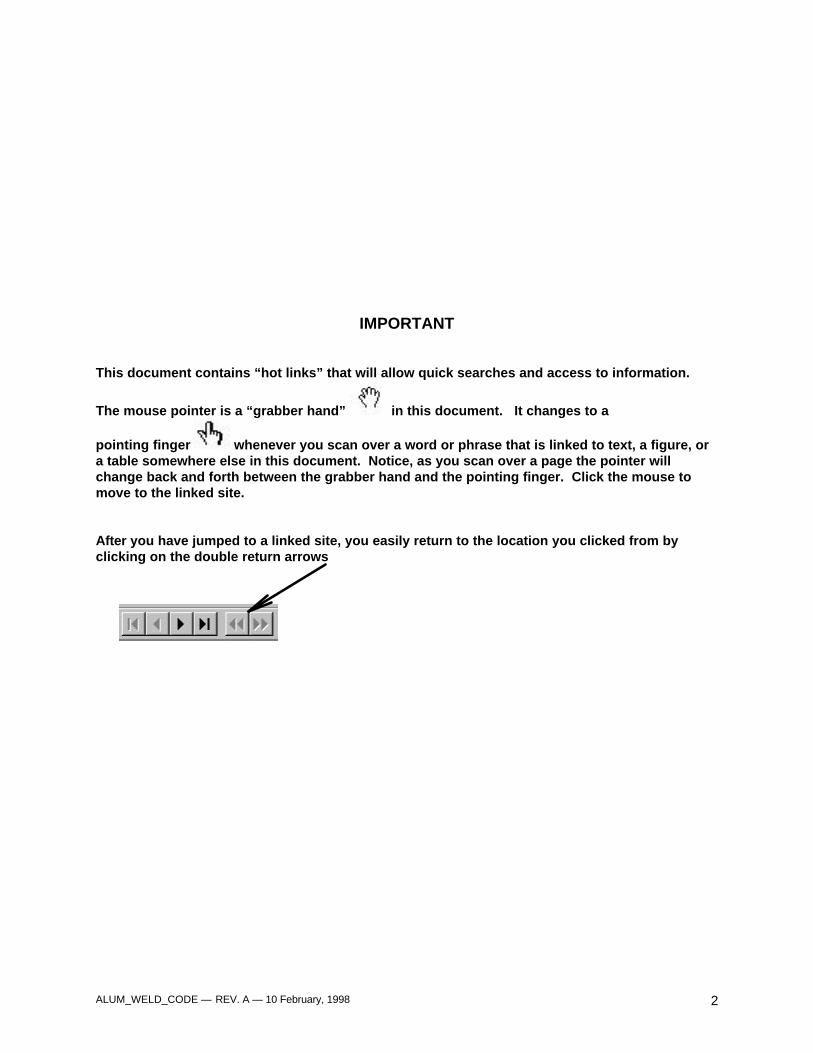
This document contains “hot links” that will allow quick searches and access to information.
The mouse pointer is a “grabber hand” in this document. It changes to a
pointing finger whenever you scan over a word or phrase that is linked to text, a figure, ora table somewhere else in this document. Notice, as you scan over a page the pointer willchange back and forth between the grabber hand and the pointing finger. Click the mouse tomove to the linked site.
After you have jumped to a linked site, you easily return to the location you clicked from byclicking on the double return arrows
ALUM_WELD_CODE — REV. A — 10 February, 1998 3
Preface
Format
This document follows the AWS format, and isbased on the current practice in the manufactureof ground combat vehicles. Therefore, thesection that normally would be included toestablish design standards has been eliminatedfrom this code. This follows the practice withinthis industry of having design performed bystructural design engineers using the latest infinite element analysis techniques.
This code has been divided into 9 sections(sections 1 through 10, with section 2, normallyapplied to design, eliminated) that can be groupedinto the following areas related to weldingmanufacture:
• General welding procedural requirements forthe qualification of welding processes and weldjoint geometries.
• Specific requirements for qualifying welders forvarious welding processes.
• Specific requirements for welds in four differentcategories:
– Stud Welding
– Non-Critical Welding
– Critical Welding (Except Ballistic Structures)
– Ballistic Welding
Generally, the requirements for welds in the latterthree categories can be related to the priormilitary specifications, as follows:
• Quality standards of Section 8, related towelding attachments, is based upon MIL-STD-372, Class B.
• Quality standards of Section 9, related towelding primary nonballistic structures, is basedupon MIL-STD-372, Class A.
• Quality standards of Section 10, related towelding structures subject to ballistic attack, isbased upon MIL-STD-1946.
For simplicity, this document can be divided intoseparate working sections. Sections 7 through 10describe the requirements for specific weldcategories and should be used to control weldingof these individual categories. They should beused in conjunction with Section 6 whichestablishes basic quality procedures.
Sections 1 through 5, excluding the nonexistentSection 2, establish the general workmanship andtechnique requirements for all aluminum welding.It also establishes the qualification of proceduresand of welders. These sections produce theframework for good welding performance in anyfacility fabricating components for our country’sdefense. They must be followed for theestablishment of an acceptable facility withwelders capable of performing the weldingneeded for this fabrication.
Revisions
This document has been designed to beaccessed on-line. Any hard copy printed fromthis file MUST be considered an uncontrolleddocument.
This has been designed to be a living documentwhich can be revised upon agreement of allparties to it. Recommendations for change willalways be considered by the committeeresponsible for maintaining the document.
Acknowledgment
This code is based on the American WeldingSociety’s ANSI/AWS D1.2 Structural WeldingCode - Aluminum.
This document was prepared by a team from theU.S. Army’s Armament Research, Developmentand Engineering Center in Dover, NJ, the U.S.Army’s Tank-Automotive and ArmamentResearch, Development and Engineering Centerin Warren, MI, and United Defense, L.P.’s GroundSystems Division’s; Aiken, SC, San Jose, CA andYork, PA sites.

ALUM_WELD_CODE — REV. A — 10 February, 1998 4
ALUM_WELD_CODE — REV. A — 10 February, 1998 5
TABLE OF CONTENTS
Preface.................................................................................................................................................3List of Tables ........................................................................................................................................9List of Figures.....................................................................................................................................11
1 GENERAL PROVISIONS.............................................................................................. 131.1 Scope .......................................................................................................................................131.2 Approval ...................................................................................................................................131.3 Materials ...................................................................................................................................131.4 Welding Processes....................................................................................................................161.5 Equipment Calibration...............................................................................................................161.6 Definitions .................................................................................................................................161.7 Welding Symbols ......................................................................................................................161.8 Safety Precautions ....................................................................................................................171.9 Standard Units Of Measurement ...............................................................................................17
3 WORKMANSHIP........................................................................................................... 193.1 General .....................................................................................................................................193.2 Preparation Of Base Material ....................................................................................................193.3 Assembly ..................................................................................................................................213.4 Control Of Distortion And Shrinkage..........................................................................................223.5 Weld Profiles ............................................................................................................................223.6 Rework/Repairs.........................................................................................................................233.7 Cleaning Of Completed Welds ..................................................................................................24
4 TECHNIQUE................................................................................................................. 25
Part A General Requirements For Gas Metal Arc, Gas Tungsten Arc, Plasma Arc(Variable Polarity) Welding ........................................................................................25
4.1 Material Requirements ..............................................................................................................254.2 Welding Processes....................................................................................................................254.3 Shielding Gases ........................................................................................................................254.4 Preheat Requirements...............................................................................................................254.5 Interpass Temperature Requirements........................................................................................254.6 Arc Strikes ................................................................................................................................254.7 Cleaning Prior To Welding` .......................................................................................................254.8 Weld Termination......................................................................................................................254.9 Backing To Prevent Melting Through ........................................................................................264.10 Peening.....................................................................................................................................264.11 Thermal Stress-Relief Treatment ..............................................................................................26
Part B Gas Metal Arc Welding .............................................................................................26
4.12 General .....................................................................................................................................264.13 Restrictions On Gas Metal Arc Welding With Single Electrode..................................................26
Part C General Requirements Gas Tungsten Arc Welding ...................................................27
4.14 General .....................................................................................................................................274.15 Tungsten Electrodes..................................................................................................................274.16 Restrictions On Gas Tungsten Arc Welding...............................................................................28
Part D Plasma Arc Welding .................................................................................................28
4.17 General .....................................................................................................................................284.18 Tungsten Electrodes..................................................................................................................284.19 Restrictions On Variable Polarity Plasma Arc Welding ..............................................................28
ALUM_WELD_CODE — REV. A — 10 February, 1998 6
Contents
5 QUALIFICATIONS OF PROCEDURES AND PERSONNEL......................................... 29
Part A General Requirements...............................................................................................29
5.1 General ....................................................................................................................................295.2 Qualification Of Welding Procedures.........................................................................................295.3 Qualification Of Welders, Welding Operators, And Tack Welders .............................................295.4 Qualification Responsibility .......................................................................................................295.5 Records.....................................................................................................................................295.6 Position Of Test Welds..............................................................................................................29
Part B Types of Tests, Test Methods and Acceptance Criteria..............................................35
5.7 Types And Purposes Of Tests ...................................................................................................355.8 Visual Examination ...................................................................................................................365.9 Tension Tests — Groove Welds................................................................................................365.10 Bend Tests — Groove Welds — Plate And Pipe .......................................................................375.11 Soundness Tests — Fillet Welds...............................................................................................435.12 Radiographic Examination ........................................................................................................44
Part C Procedure Qualification..............................................................................................46
5.13 General .....................................................................................................................................465.14 Limits Of Qualified Positions For Procedures ............................................................................465.15 Preparation Of Test Weldment — Procedure Qualification........................................................485.16 Limitation of Variables — Procedure Qualification.....................................................................485.17 Tests — Procedure Qualification ...............................................................................................505.18 Retests......................................................................................................................................55
Part D Performance Qualification..........................................................................................55
5.19 General .....................................................................................................................................555.20 Limits of Qualified Positions for Performance............................................................................555.21 Preparation of Test Weldments — Performance Qualification...................................................585.22 Limitation of Variables — Welder Performance Qualification ....................................................605.23 Limitation of Variables — Welding Operator Performance Qualification ....................................605.24 Limitation of Variables — Tack Welder Performance Qualification............................................605.25 Tests — Performance Qualification...........................................................................................625.26 Retests......................................................................................................................................635.27 Period of Effectiveness .............................................................................................................63
6 INSPECTION ................................................................................................................ 67
Part A General Requirements...............................................................................................67
6.1 General .....................................................................................................................................676.2 Inspection of Materials ..............................................................................................................676.3 Inspection of Welding Procedure Qualification and Equipment..................................................676.4 Inspection of Welder, Welding Operator, and Tack Welder Qualifications .................................686.5 Inspection of Work and Records................................................................................................686.6 Obligations of the Contractor.....................................................................................................686.7 Nondestructive Testing .............................................................................................................68
Part B Radiographic Inspection.............................................................................................69
6.8 General .....................................................................................................................................696.9 Extent of Testing .......................................................................................................................696.10 Radiographic Procedures ..........................................................................................................696.11 Acceptability of Welds ..............................................................................................................736.12 Examination, Report, and Disposition of Radiographs ...............................................................73
ALUM_WELD_CODE — REV. A — 10 February, 1998 7
Contents
Part C Ultrasonic Testing of Groove Welds ...........................................................................73
6.13 General .....................................................................................................................................73
7 STUD WELDING .......................................................................................................... 75
Part A General Requirements...............................................................................................75
7.1 General ........................................................................................................................................75
Part B Arc Stud Welding.......................................................................................................75
7.2 General Requirements ..............................................................................................................757.3 Material Requirements ..............................................................................................................757.4 Workmanship............................................................................................................................757.5 Technique .................................................................................................................................767.6 Qualification Requirements .......................................................................................................767.7 Operator and Preproduction Qualification .................................................................................787.8 Acceptance Criteria — Production Welds..................................................................................787.9 Mislocated Studs.......................................................................................................................787.10 Repair of Misapplied Studs........................................................................................................78
Part C Capacitor Discharge Stud Welding.............................................................................79
7.11 General Requirements ..............................................................................................................797.12 Material Requirements ..............................................................................................................797.13 Workmanship............................................................................................................................797.14 Technique .................................................................................................................................797.15 Qualification Requirements .......................................................................................................797.16 Operator and Preproduction Qualification..................................................................................817.17 Acceptance Criteria — Production Welds..................................................................................817.18 Mislocated Studs.......................................................................................................................817.19 Repair of Misapplied Studs........................................................................................................81
8 NON-CRITICAL WELDING........................................................................................... 83
Part A General Requirements...............................................................................................83
8.1 Application ................................................................................................................................838.2 Base Metal ................................................................................................................................838.3 Filler Metal ................................................................................................................................84
Part B Workmanship.............................................................................................................84
8.4 Dimensional Tolerances............................................................................................................848.5 Temporary Welds......................................................................................................................848.6 Weld Termination......................................................................................................................848.7 Quality of Welds........................................................................................................................84
9 CRITICAL WELDING (Except Ballistic Structures).................................................... 87
Part A General Requirements...............................................................................................87
9.1 Application ................................................................................................................................879.2 Base Metal ................................................................................................................................879.3 Filler Metal ................................................................................................................................87
Part B Workmanship.............................................................................................................88
9.4 Dimensional Tolerances............................................................................................................889.5 Temporary Welds......................................................................................................................889.6 Weld Terminations ....................................................................................................................889.7 Quality of Welds........................................................................................................................88
ALUM_WELD_CODE — REV. A — 10 February, 1998 8
Contents
10 BALLISTIC WELDING.................................................................................................. 91
Part A General Requirements...............................................................................................91
10.1 Application ................................................................................................................................9110.2 Base Metal ................................................................................................................................9110.3 Filler Metal ................................................................................................................................91
Part B Workmanship.............................................................................................................91
10.4 Temporary Welds......................................................................................................................9110.5 Weld Terminations ....................................................................................................................9110.6 Ballistic Certification..................................................................................................................9110.7 Macro Specimens .....................................................................................................................9310.8 Quality of Welds........................................................................................................................9310.9 Ballistic Shock Test Procedure ..................................................................................................95
APPENDICES ....................................................................................................................... 99
APPENDIX A – STANDARD FORMS.................................................................................. 101
APPENDIX B – WELD TYPES............................................................................................ 119
ALUM_WELD_CODE — REV. A — 10 February, 1998 9
LIST OF TABLES
Table1.1 Aluminum Alloy Products Available for Structural Applications..................................................141.2 Recommended Aluminum Alloy Filler Metals for Structural Welding of Various Aluminum
Alloys ........................................................................................................................................153.1 Limit of Acceptability and Repair of Cut Edge Discontinuities in Plate .......................................204.1 Typical Current Ranges for Tungsten Electrodes.......................................................................274.2 Typical Chemical Composition of Tungsten Electrodes .............................................................285.1 Tensile Strength of Welded Aluminum Alloys (GTAW or GMAW With No Postweld Heat
Treatment) ................................................................................................................................405.2 Procedure Qualification - Type and Position Limitations ............................................................505.3 Number and Type of Test Specimens and Range of Thickness Qualified — Procedure
Qualification; Complete Joint Penetration Groove Welds ..........................................................525.4 Number and Type of Test Specimens and Range of Thickness Qualified—Procedure
Qualification; Partial Joint Penetration Groove Welds ...............................................................545.5 Number and Type of Test Specimens and Range of Thickness Qualified —Procedure
Qualification Fillet Welds ..........................................................................................................575.6 Welder Performance Qualification—Type of Weld and Position Limitations ..............................585.7 Number and Type of Test Specimens and Range of Thickness Qualified Welder and
Welding Operator Qualification .................................................................................................646.1 Penetrameter Requirements......................................................................................................707.1 Minimum Fillet Weld Size for Small Diameter Studs .................................................................767.2 Minimum Required Torque Values and Tension Loads for Arc Stud Welding
(F-22 Aluminum Alloy Studs).....................................................................................................777.3 Minimum Required Torque Values and Tension Loads for Capacitor Discharge Stud
Welding (F-22 Aluminum Alloy Studs).......................................................................................809.1 Maximum Acceptable Porosity in Radiographs for Any 3 in. Length of Weld
(Dynamically Loaded)................................................................................................................8910.1 Sample Inspection Frequency Table .........................................................................................9510.2 “Consecutives” Table for Random Positions ..............................................................................9510.3 Striking Velocity Requirements for 5083 Aluminum Alloy Using the 75 mm Aluminum
M1002A Plate Proofing Projectile..............................................................................................9710.4 Striking Velocity Requirements for 7039 Aluminum Alloy Using the 75-mm Aluminum,
M1002A Plate Proofing Projectile..............................................................................................9710.5 Striking Velocity Requirements for 5083 Aluminum Alloy Using the 57-mm Aluminum
M1001A Plate Proofing Projectile..............................................................................................9710.6 Striking Velocity Requirements for 7039 Aluminum Alloy Using the 57-MM Aluminum
M1001A Plate Proofing Projectile..............................................................................................9710.7 Striking Velocity Requirements for 2519 Alloy Aluminum Armor Weldments Using the
75-mm, M1002A Aluminum Plate Proofing Projectile ................................................................97

ALUM_WELD_CODE — REV. A — 10 February, 1998 10
ALUM_WELD_CODE — REV. A — 10 February, 1998 11
LIST OF FIGURESFigure3.1 Edge Discontinuities in Cut Plate....................................................................................................213.2 Maximum Allowable Root Opening.................................................................................................223.3 Acceptable and Unacceptable Weld Profiles ..................................................................................235.1 Positions of Groove Welds.............................................................................................................305.2 Positions of Fillet Welds.................................................................................................................315.3 Position of Test Plates for Groove Welds .......................................................................................325.4 Position of Test Plates for Pipe or Tubing for Groove Welds ..........................................................335.5 Position of Test Plates for Fillet Welds ...........................................................................................345.6 Position for Test Pipes for Fillet Welds...........................................................................................355.7 Reduced Section Tension Specimens — Plate and Tubing ............................................................385.9 Alternate Reduced Section Tension Specimen for Pipe [3 in. (75 mm) Diameter or Less ...............395.10 Full Section Tension Specimens — Small Diameter Pipe [3 in. (75 mm) Diameter or Less] ...........395.11 Transverse Side Bend Specimens..................................................................................................415.12 Transverse Face- and Root-Bend Specimens ................................................................................425.13 Longitudinal Face- and Root-Bend Specimens ...............................................................................435.14 Plunger-Type Guided Bend Jig.......................................................................................................445.15 Roller-Type Guided Bend Jig .........................................................................................................455.16 Wrap-Around Guided Bend Jig.......................................................................................................475.17 Fillet Weld Soundness Test for Procedure Qualification — Option 1 — Plate.................................475.18 Fillet Weld Soundness Test for Procedure Qualification — Option 1 — Pipe..................................485.19 Fillet Weld Soundness Test for Procedure Qualification — Option 2 — Root Bend Test — Plate ...495.20 Location of Test Specimens for Procedure Qualification — Plate ...................................................535.21 Location of Test Specimens on Welded Test Pipe..........................................................................545.22 Location of Test Specimens for Square and Rectangular Tubing....................................................545.23 Location of Test Specimens for Job Size Pipe or Tubing 1/16 in. through 3/8 in. Wall Thickness ...565.24 Location of Test Specimens for Job Size Pipe or Tubing Over 3/8 in. Wall Thickness....................565.25 Test Plate for Unlimited Thickness — Performance Qualification — Option 1 —
All Positions ...................................................................................................................................595.26 Test Plate for Unlimited Thickness — Option 2 — Horizontal Position Only ...................................605.27 Test Plate for Limited Thickness — All Positions — Performance Qualification..............................615.28 Optional Test Plate for Limited Thickness — Horizontal Position —
Performance Qualification..............................................................................................................615.29 Tubular Groove Weld — Performance Qualification — Without Backing........................................615.30 Tubular Groove Weld — Performance Qualification — Without Backing (Alternative
to Figure 5.29)................................................................................................................................615.31 Tubular Groove Weld — Performance Qualification With Backing .................................................625.32 Test Joint for T-, Y-, and K-connections on Pipe or Square or Rectangular Tubing —
Performance Qualification..............................................................................................................625.33 Test Weldment for Fillet Welds Only — Performance Qualification — Option 1 .............................625.34 Location of Test Specimens on Welded Test Pipe and Square and Rectangular Tubing —
Performance Qualification`.............................................................................................................656.1 Radiographic Identification and Penetrameter Locations on Approximately Equal Thickness
Joints .............................................................................................................................................716.2 Radiographic Identification and Penetrameter Locations on Transitions Joints ..............................716.3 Penetrameter Design .....................................................................................................................727.1 Stud Welding Bend Jig...................................................................................................................777.2 Torque Testing Arrangement For Stud Welds.................................................................................778.1 Permissible Undercut Values..........................................................................................................848.2 Permissible Cracks the Stop Region of a Weld ..............................................................................8510.1 Example of Specimen Size, or Orientation, and Markings for Ballistic Test. ...................................92

ALUM_WELD_CODE — REV. A — 10 February, 1998 12
ALUM_WELD_CODE — REV. A — 10 February, 1998 13
UDLP/TACOM
Ground Combat Vehicle Welding Code — AluminumJuly, 1996
1. General Provisions
1.1 Scope
This Code covers welding requirementsapplicable to welding ground combat aluminumalloy structures and components. It is to be usedin conjunction with appropriate complementarycodes or specifications for materials design andconstruction. It is not intended to supplant codesdeveloped for use in specialized fabrication, suchas the ASME Boiler and Pressure Vessel Code, oraerospace codes; it is appropriate for use infabrication of ballistic and nonballistic primarystructures, supporting structures andappurtenances. Requirements that areessentially common to all types of structures arecovered in sections 1 through 7, while provisionsrelating exclusively to quality requirements basedupon the intended use of the weldments areincluded in sections 8, 9 and 10.
1.2 Approval
All reference to a need for approval shall beinterpreted to mean approval by the Government,or the duly designated person who acts for and onbehalf of the Government in all matters withinthe scope of this code.
In addition, where Contractor approvals shall berequired, the term Contractor shall refer to theappropriate Prime Contractor Weld Engineeringand/or Quality Engineering personnel.
1.3 Materials
1.3.1 Base Metals
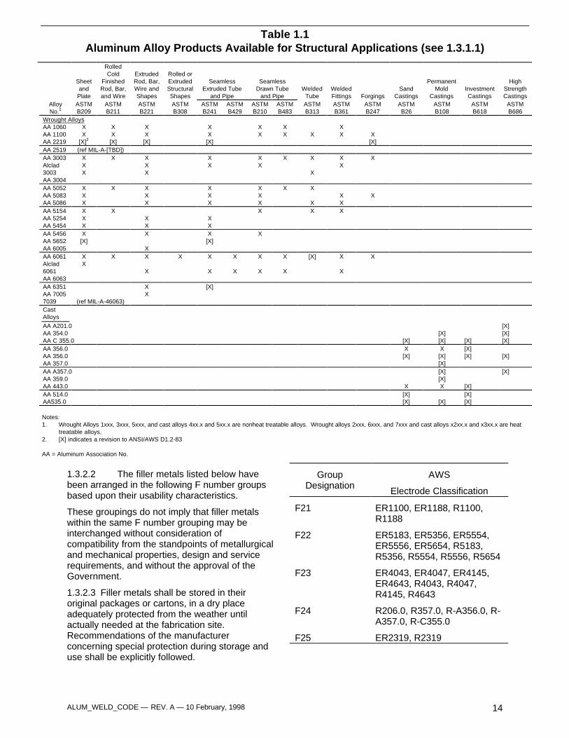
1.3.1.1 Aluminum alloys approved for use inthis code are listed under ASTM and former
military specifications, as appropriate, in Table1.1. Other aluminum alloys may be used onlywhen approved by the Government or listed as analternate in the Technical Data Package (TDP).
1.3.1.2 To reduce the number of weldingprocedure qualifications required, the followinggroupings of base materials listed in Table 1.1have been established. They are basedessentially on comparable base metalcharacteristics, such as composition, weldability,and mechanical properties:
M-Number Listing
M21 – 1060, 1100, ALCLAD 3003, 5005 5050
M22 – 3004, ALCLAD 3004, 5052, 5254, 5456,5652
M23 – 6005, 6061, ALCLAD 6061, 6063, 6351
M24 – 2219
M25 – 5083, 5086, 5456
M26 – A201.1, 354.0, 355.0, 356.0, A356.0,357.0, A357.0, 359.0, 514.0, 535.0
M27 – 7005, 7039
1.3.2 Filler Metals
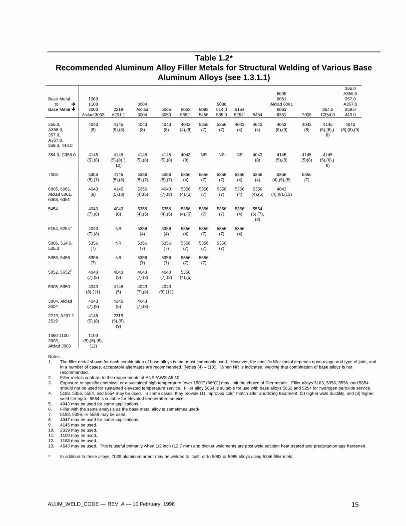
1.3.2.1 Filler metals shall comply with all therequirements set forth in the latest edition ofANSI/AWS A5.10, Specification for BareAluminum and Aluminum Alloy WeldingElectrodes and Rods. Table 1.2 lists filler alloysrecommended for use with pertinent basealuminum alloys for general structuralapplications.
ALUM_WELD_CODE — REV. A — 10 February, 1998 14
1.3.2.2 The filler metals listed below havebeen arranged in the following F number groupsbased upon their usability characteristics.
These groupings do not imply that filler metalswithin the same F number grouping may beinterchanged without consideration ofcompatibility from the standpoints of metallurgicaland mechanical properties, design and servicerequirements, and without the approval of theGovernment.
1.3.2.3 Filler metals shall be stored in theiroriginal packages or cartons, in a dry placeadequately protected from the weather untilactually needed at the fabrication site.Recommendations of the manufacturerconcerning special protection during storage anduse shall be explicitly followed.
GroupDesignation
AWS
Electrode Classification
F21 ER1100, ER1188, R1100,R1188
F22 ER5183, ER5356, ER5554,ER5556, ER5654, R5183,R5356, R5554, R5556, R5654
F23 ER4043, ER4047, ER4145,ER4643, R4043, R4047,R4145, R4643
F24 R206.0, R357.0, R-A356.0, R-A357.0, R-C355.0
F25 ER2319, R2319
Table 1.1Aluminum Alloy Products Available for Structural Applications (see 1.3.1.1)
Sheetand
Plate
RolledCold
FinishedRod, Bar,and Wire
ExtrudedRod, Bar,Wire andShapes
Rolled orExtrudedStructuralShapes
SeamlessExtruded Tube
and Pipe
SeamlessDrawn Tube
and PipeWelded
TubeWeldedFittings Forgings
SandCastings
PermanentMold
CastingsInvestmentCastings
HighStrengthCastings
AlloyNo.1
ASTMB209
ASTMB211
ASTMB221
ASTMB308
ASTMB241
ASTMB429
ASTMB210
ASTMB483
ASTMB313
ASTMB361
ASTMB247
ASTMB26
ASTMB108
ASTMB618
ASTMB686
Wrought AlloysAA 1060AA 1100AA 2219
XX
[X]2
XX
[X]
XX
[X]
XX
[X]
XX
XX X
XX X
[X]AA 2519 (ref MIL-A-[TBD])AA 3003Alclad3003AA 3004
XXX
X XXX
XX
XX
X X
X
XX
X
AA 5052AA 5083AA 5086
XXX
X XXX
XXX
XXX
X X
XXX
X
AA 5154AA 5254AA 5454
XXX
XXX
XX
X X X
AA 5456AA 5652AA 6005
X[X]
X
X
X[X]
X
AA 6061Alclad6061AA 6063
XX
X X
X
X X
X
X
X
X
X
X
X
[X] X
X
X
AA 6351AA 70057039 (ref MIL-A-46063)
XX
[X]
CastAlloys
AA A201.0AA 354.0AA C 355.0 [X]
[X][X] [X]
[X][X][X]
AA 356.0AA 356.0AA 357.0
X[X]
X[X][X]
[X][X] [X]
AA A357.0AA 359.0AA 443.0 X
[X][X]X [X]
[X]
AA 514.0AA535.0
[X][X] [X]
[X][X]
Notes:1. Wrought Alloys 1xxx, 3xxx, 5xxx, and cast alloys 4xx.x and 5xx.x are nonheat treatable alloys. Wrought alloys 2xxx, 6xxx, and 7xxx and cast alloys x2xx.x and x3xx.x are heat
treatable alloys.2. [X] indicates a revision to ANSI/AWS D1.2-83
AA = Aluminum Association No.
ALUM_WELD_CODE — REV. A — 10 February, 1998 15
Table 1.2*Recommended Aluminum Alloy Filler Metals for Structural Welding of Various Base
Aluminum Alloys (see 1.3.1.1)
Base Metal to èBase Metal ê
106011003003
Alclad 30032219
A201.1
3004Alclad3004
50055050
505256523
50835456
5086514.0535.0
515452543 5454
60056061
Alclad 606160636351 7005
354.0C354.0
356.0A356.0357.0
A357.0359.0443.0
356.0,A356.0,357.0,A357.0,359.0, 443.0
4043(8)
4145(5),(8)
4043(8)
4043(8)
4043(4),(8)
5356(7)
5356(7)
4043(4)
4043(4)
4043(8),(9)
4043(8)
4145(5),(6),(
8)
4043(6),(8),(9)
354.0, C355.0 4145(5),(8)
4145(5),(8),(
10)
4145(5),(8)
4145(5),(8)
4043(8)
NR NR NR 4043(8)
4145(5),(8)
4145(5)(8)
4145(5),(6),(
8)
7005 5356(5),(7)
4145(5),(8)
5356(5),(7)
5356(5),(7)
5356(4)
5556(7)
5356(7)
5356(4)
5356(4)
5356(4),(5),(8)
5356(7)
6005, 6061,Alclad 6061,6063, 6351
4043(8)
4145(5),(8)
5356(4),(5)
4043(7),(8)
5356(4),(5)
5356(7)
5356(7)
5356(4)
5356(4),(5)
4043(4),(8),(13)
5454 4043(7),(8)
4043(8)
5356(4),(5)
5356(4),(5)
5356(4),(5)
5356(7)
5356(7)
5356(4)
5554(5),(7),
(8)
5154, 52543 4043(7),(8)
NR 5356(4)
5356(4)
5356(4)
5356(7)
5356(7)
5356(4)
5086, 514.0,535.0
5356(7)
NR 5356(7)
5356(7)
5356(7)
5356(7)
5356(7)
5083, 5456 5356(7)
NR 5356(7)
5356(7)
5356(7)
5556(7)
5052, 56523 4043(7),(8)
4043(8)
4043(7),(8)
4043(7),(8)
5356(4),(5)
5005, 5050 4043(8),(11)
4145(5)
4043(7),(8)
4043(8),(11)
3004, Alclad3004
4043(7),(8)
4145(5)
4043(7),(8)
2219, A201.12519
4145(5),(8)
2319(5),(8),
(9)
1060 11003003,Alclad 3003
1100(5),(6),(8),
(12)
Notes:1. The filler metal shown for each combination of base alloys is that most commonly used. However, the specific filler metal depends upon usage and type of joint, and
in a number of cases, acceptable alternates are recommended. [Notes (4) – (13)]. When NR is indicated, welding that combination of base alloys is notrecommended.
2. Filler metals conform to the requirements of ANSI/AWS A5.10.3. Exposure to specific chemical, or a sustained high temperature [over 150ºF (66ºC)] may limit the choice of filler metals. Filler alloys 5183, 5356, 5556, and 5654
should not be used for sustained elevated temperature service. Filler alloy 5654 is suitable for use with base alloys 5652 and 5254 for hydrogen peroxide service.4. 5183, 5356, 5554, and 5654 may be used. In some cases, they provide (1) improved color match after anodizing treatment, (2) higher weld ductility, and (3) higher
weld strength. 5554 is suitable for elevated temperature service.5. 4043 may be used for some applications.6. Filler with the same analysis as the base metal alloy is sometimes used/7. 5183, 5356, or 5556 may be used.8. 4047 may be used for some applications.9. 4145 may be used.10. 2319 may be used.11. 1100 may be used.12. 1188 may be used.13. 4643 may be used. This is useful primarily when 1/2 inch (12.7 mm) and thicker weldments are post weld solution heat treated and precipitation age hardened.
* In addition to these alloys, 7039 aluminum armor may be welded to itself, or to 5083 or 5086 alloys using 5356 filler metal.
ALUM_WELD_CODE — REV. A — 10 February, 1998 16
1.3.3 Shielding Gases
1.3.3.1 The shielding gas in conventionalwelding of aluminum shall be welding-gradeargon, complying with CGA specification Grade Cminimum. Where special circumstances exist,i.e., the need for deep penetration (as in weldingvery thick sections), the use of welding-gradehelium or a mixture of welding grade argon andwelding-grade helium may be used in accordancewith the requirements of section 5.16.
1.3.3.2 Shielding gases shall be stored in andused from the containers in which they aresupplied or from a central storage tankdistribution system which is replenished by thegas supplier. The entire handling system shall bedesigned to prevent contamination.
1.4 Welding Processes
This code covers the requirements for weldingaluminum alloys by the following processes:
(1) GMAW — gas metal arc welding
(2) GMAW-P— pulsed gas metal arc welding
(3) GTAW — gas tungsten arc welding
(4) PAW-VP — plasma arc welding withvariable polarity.
(5) SW — stud welding
(6) GMAW-AU, -ME, and -RO — automatic,mechanized, or robotic gas metal arcwelding
The welding procedures for these processes shallcomply with the provisions of sections 1 through 5and, in addition, sections 8, 9, or 10, asapplicable.
1.5 Equipment Calibration
The manufacturer is required to develop andmaintain a welding equipment calibrationprogram. This program shall consist of, as aminimum, an annual comparison check of themachine output with instrumentation calibratedusing standards traceable to the National Instituteof Standards and Technology (NIST). Thestandard may be a load bank, voltmeter/ammeter,clamp-on meter, etc.
Machine output for amperage and voltage mustbe within ± 10% of full scale. Properdocumentation and evidence of theimplementation must be maintained and issubject to random audit. If leads are in excess of
10 ft. in length, calibration will be performed atthe nozzle. Either gage correction or aconversion chart will be used.
1.6 Definitions
The welding terms used in this Code shall beinterpreted in accordance with the definitionsgiven in the latest edition of ANSI/AWS A3.0,Standard Welding Terms and Definitions.
Terms not included in ANSI/AWS A3.0 aredefined below:
Reenetrant corner – A corner directed inward (asopposed to an outside corner)
Fins – Metal on a casting caused by an imperfectmold or die
Flange – A rib or rim provided for strength, forguiding, or for attachment to another object
Transition area – An area in which the thicknessvaries from thicker to thinner
Shrinkage – A shrinkage crack
Cope holes – A hole formed to conform to theshape of another member
Bearing joint – Welded joint positioned to absorbthe load
Faying surfaces – The mating surface of amember that is touching or in closeproximity to another member to which it isto be joined
Built-up members – A member that has beenclad, buttered, or in some way built up withweld metal
Modified PQR – A PQR that has been developedfrom existing procedures qualified from awelding military standard or specification,and grandfathered into an AWS PQRformat
Modified WPS – A WPS that has been createdfrom a modified PQR(s) developed from anexisting workmanship sample per MIL-STDor specification.
1.7 Welding Symbols
Welding symbols used in drawings, sketches,erection plans, procedure specifications, etc.,shall be those shown in the latest edition ofANSI/AWS A2.4, Symbols for Welding, Brazing,and Nondestructive Examination. Special
ALUM_WELD_CODE — REV. A — 10 February, 1998 17
conditions shall be fully explained by added notesor details.
1.8 Safety Precautions
Note: This Code may involve hazardousmaterials, operations,. and equipment. The Codedoes not purport to address all of the safetyproblems associated with its use. It is theresponsibility of the user to establish appropriatesafety and health practices. The user should
determine the applicability of any regulatorylimitations prior to use.
Adequate safety precautions, including ventilationof the work area shall be taken in accordance withthe requirements of the latest edition ofANSI/ASC Z49.1, Safety in Welding and Cutting.
1.9 Standard Units of Measurement
The values stated in U.S. customary units are tobe regarded as the standard..

ALUM_WELD_CODE — REV. A — 10 February, 1998 18
ALUM_WELD_CODE — REV. A — 10 February, 1998 19
3. Workmanship
3.1 General
3.1.1 All applicable subsections in this sectionshall be adhered to in the production andinspection of welded assemblies and structuresproduced under this Code.
3.1.2 All welding and cutting equipment shallbe so designed and manufactured and shall bemaintained in such operating condition thatqualified welders, welding operators and tackwelders are able to follow the procedures andattain the results prescribed elsewhere in thisCode.
3.1.3 Welding shall not be done when theparent metal temperature is lower than 55° F.This does not mean the ambient environmentaltemperature, but the temperature in theimmediate vicinity of the weld. If the ambientenvironmental temperature is below 32° F, aheated structure or shelter may be provided whichwill maintain the temperature adjacent to theweldment at 55° F or higher. When thetemperature of the weld area and surroundingbase metal is below the allowed minimumtemperature, the base metal shall be preheated,but not to exceed 250° F, so that the parts onwhich weld metal is being deposited are at, orabove, the allowed minimum temperature for adistance equal to the thickness of the parts beingwelded, but not less than 3 in. both laterally and inadvance of the welding. This heating is to bedone before welding is started to drive moisturefrom the region of the weld.
3.1.4 Welding shall not be done when thesurfaces are wet or exposed to rain, mist, snow,sleet, frost, or excessive wind, or when welders,welding operators or tack welders are exposed tosuch inclement conditions.
3.1.5 The sizes and lengths of welds shall bethose specified by the design requirements anddetail drawings.
3.1.6 The locations of welds shall not bechanged from those shown on the drawings.
3.1.7 The use of anti-spatter compound shallbe prohibited.
3.2 Preparation of Base Material
3.2.1 Edge preparation can be accomplishedby shearing, sawing, plasma arc cutting, chipping,planing, milling or routing. Grinding of aluminum,except as a final weld contouring and finishingoperation, is not recommended.
3.2.1.1 When grinding is necessary, careshall be taken to select nonloading type abrasivesspecifically intended for use on aluminum, andthe abrasives shall be maintained free oflubricants and other foreign material.
3.2.1.2 All exposed cut edges on alloy 7039must be buttered if not part of a weld joint.
3.2.2 Surfaces and edges to be welded shall besmooth, uniform, and free from fins, tears, andcracks.
3.2.3 In plasma arc cutting, the arc shall beadjusted and manipulated so as to avoid cuttingbeyond (inside) the prescribed lines. The surfaceroughness of the cut surfaces shall be no greaterthan that defined by the American NationalStandards Institute (ANSI B46.1, Surface Texture)value of 1000 µin. for material up to 4 in. thickand 2000 µin for material 4 in. to 8 in. thick,except that members not subject to calculatedstress at the ends may meet the surfaceroughness value of 2000 µin. Roughnessexceeding the permissible amount and occasionalnotches or gouges more than 3/16 in. deep, onotherwise satisfactory surfaces shall be faired intothe cut surface by machining or grinding to aslope not exceeding one in ten. In cut edges,occasional notches or gouges less than 7/16 in,deep in material up to 4 in. in thickness, or lessthan 5/8 in. deep in material more than 4 in. thickmay, with the approval of the Material ReviewBoard (MRB), be repaired by welding inaccordance with approved repair procedures.
3.2.4 Visual Inspection and Repair of Cut
Edges1
3.2.4.1 In the determination of limits ofinternal discontinuities revealed on sheared or cutedges and caused by tearing, inclusions, ordelamination (seldom encountered in aluminumproducts), the amount of metal removed shall be
ALUM_WELD_CODE — REV. A — 10 February, 1998 20
the minimum necessary to remove thediscontinuity or to determine that the permissiblelimit of the discontinuity is not exceeded. Theremoval of metal for this purpose may be donefrom either the plate surface or a cut edge. Cutedges may exist at any angle with respect to thedirection of rolling.
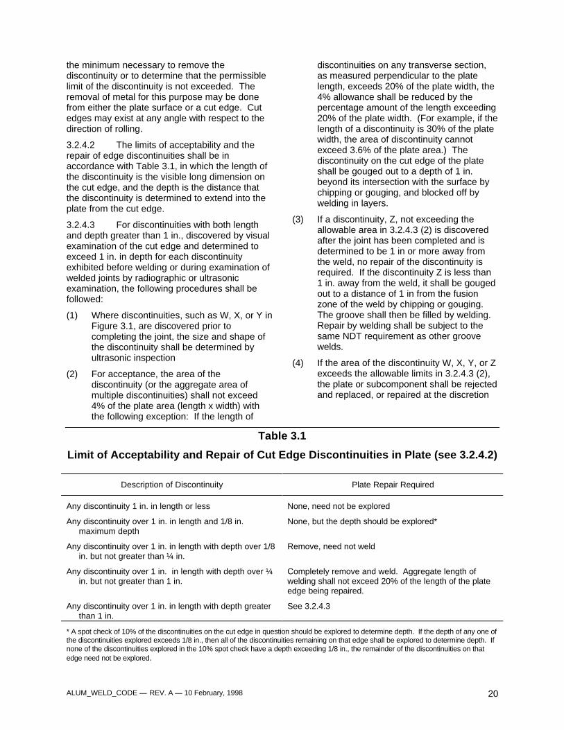
3.2.4.2 The limits of acceptability and therepair of edge discontinuities shall be inaccordance with Table 3.1, in which the length ofthe discontinuity is the visible long dimension onthe cut edge, and the depth is the distance thatthe discontinuity is determined to extend into theplate from the cut edge.
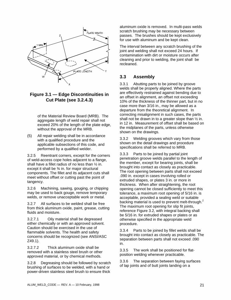
3.2.4.3 For discontinuities with both lengthand depth greater than 1 in., discovered by visualexamination of the cut edge and determined toexceed 1 in. in depth for each discontinuityexhibited before welding or during examination ofwelded joints by radiographic or ultrasonicexamination, the following procedures shall befollowed:
(1) Where discontinuities, such as W, X, or Y inFigure 3.1, are discovered prior tocompleting the joint, the size and shape ofthe discontinuity shall be determined byultrasonic inspection
(2) For acceptance, the area of thediscontinuity (or the aggregate area ofmultiple discontinuities) shall not exceed4% of the plate area (length x width) withthe following exception: If the length of
discontinuities on any transverse section,as measured perpendicular to the platelength, exceeds 20% of the plate width, the4% allowance shall be reduced by thepercentage amount of the length exceeding20% of the plate width. (For example, if thelength of a discontinuity is 30% of the platewidth, the area of discontinuity cannotexceed 3.6% of the plate area.) Thediscontinuity on the cut edge of the plateshall be gouged out to a depth of 1 in.beyond its intersection with the surface bychipping or gouging, and blocked off bywelding in layers.
(3) If a discontinuity, Z, not exceeding theallowable area in 3.2.4.3 (2) is discoveredafter the joint has been completed and isdetermined to be 1 in or more away fromthe weld, no repair of the discontinuity isrequired. If the discontinuity Z is less than1 in. away from the weld, it shall be gougedout to a distance of 1 in from the fusionzone of the weld by chipping or gouging.The groove shall then be filled by welding.Repair by welding shall be subject to thesame NDT requirement as other groovewelds.
(4) If the area of the discontinuity W, X, Y, or Zexceeds the allowable limits in 3.2.4.3 (2),the plate or subcomponent shall be rejectedand replaced, or repaired at the discretion
Table 3.1
Limit of Acceptability and Repair of Cut Edge Discontinuities in Plate (see 3.2.4.2)
Description of Discontinuity Plate Repair Required
Any discontinuity 1 in. in length or less None, need not be explored
Any discontinuity over 1 in. in length and 1/8 in.maximum depth
None, but the depth should be explored*
Any discontinuity over 1 in. in length with depth over 1/8in. but not greater than ¼ in.
Remove, need not weld
Any discontinuity over 1 in. in length with depth over ¼in. but not greater than 1 in.
Completely remove and weld. Aggregate length ofwelding shall not exceed 20% of the length of the plateedge being repaired.
Any discontinuity over 1 in. in length with depth greaterthan 1 in.
See 3.2.4.3
* A spot check of 10% of the discontinuities on the cut edge in question should be explored to determine depth. If the depth of any one ofthe discontinuities explored exceeds 1/8 in., then all of the discontinuities remaining on that edge shall be explored to determine depth. Ifnone of the discontinuities explored in the 10% spot check have a depth exceeding 1/8 in., the remainder of the discontinuities on thatedge need not be explored.
ALUM_WELD_CODE — REV. A — 10 February, 1998 21
Figure 3.1 — Edge Discontinuities inCut Plate (see 3.2.4.3)
of the Material Review Board (MRB). Theaggregate length of weld repair shall notexceed 20% of the length of the plate edge,without the approval of the MRB.
(5) All repair welding shall be in accordancewith a qualified procedure and theapplicable subsections of this code, andperformed by a qualified welder.
3.2.5 Reentrant corners, except for the cornersof weld-access cope holes adjacent to a flange,shall have a fillet radius of no less than ½ in.except it shall be ¾ in. for major structuralcomponents. The fillet and its adjacent cuts shallmeet without offset or cutting past the point oftangency.
3.2.6 Machining, sawing, gouging, or chippingmay be used to back gouge, remove temporarywelds, or remove unacceptable work or metal.
3.2.7 All surfaces to be welded shall be freefrom thick aluminum oxide, paint, grease, cuttingfluids and moisture.
3.2.7.1 Oily material shall be degreasedeither chemically or with an approved solvent.Caution should be exercised in the use offlammable solvents. The health and safetyconcerns should be recognized (see ANSI/ASCZ49.1).
3.2.7.2 Thick aluminum oxide shall beremoved with a stainless steel brush or otherapproved material, or by chemical methods.
3.2.8 Degreasing should be followed by scratchbrushing of surfaces to be welded, with a hand orpower-driven stainless steel brush to ensure thick
aluminum oxide is removed. In multi-pass weldsscratch brushing may be necessary betweenpasses. The brushes should be kept exclusivelyfor use with aluminum and be kept clean.
The interval between any scratch brushing of thejoint and welding shall not exceed 24 hours. Ifcontamination with dirt or moisture occurs aftercleaning and prior to welding, the joint shall berecleaned.
3.3 Assembly
3.3.1 Abutting parts to be joined by groovewelds shall be properly aligned. Where the partsare effectively restrained against bending due toan offset in alignment, an offset not exceeding10% of the thickness of the thinner part, but in nocase more than 3/16 in., may be allowed as adeparture from the theoretical alignment. Incorrecting misalignment in such cases, the partsshall not be drawn in to a greater slope than ½ in.in 12 in. Measurement of offset shall be based onthe midplanes of the parts, unless otherwiseshown on the drawings.
3.3.2 Welding grooves which vary from thoseshown on the detail drawings and procedurespecifications shall be referred to MRB.
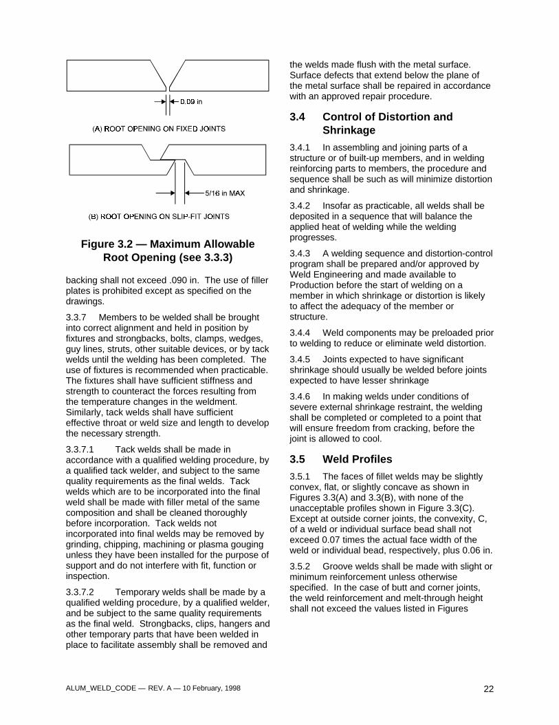
3.3.3 Parts to be joined by partial jointpenetration groove welds parallel to the length ofthe member, except for bearing joints, shall bebrought into contact as closely as practicable.The root opening between parts shall not exceed.090 in. except in cases involving rolled orextruded shapes, or plates 3 in. or more inthickness. When after straightening, the rootopening cannot be closed sufficiently to meet thistolerance, a maximum root opening of 5/16 in. isacceptable, provided a sealing weld or suitablebacking material is used to prevent melt-through.2
The maximum root opening for slip fit joints,reference Figure 3.2, with integral backing shallbe 5/16 in. for extruded shapes or plates or asotherwise specified in the appropriate weldprocedure.
3.3.4 Parts to be joined by fillet welds shall bebrought into contact as closely as practicable. Theseparation between parts shall not exceed .090in.
3.3.5 The work shall be positioned for flat-position welding whenever practicable.
3.3.6 The separation between faying surfacesof lap joints and of butt joints landing on a
ALUM_WELD_CODE — REV. A — 10 February, 1998 22
Figure 3.2 — Maximum AllowableRoot Opening (see 3.3.3)
backing shall not exceed .090 in. The use of fillerplates is prohibited except as specified on thedrawings.
3.3.7 Members to be welded shall be broughtinto correct alignment and held in position byfixtures and strongbacks, bolts, clamps, wedges,guy lines, struts, other suitable devices, or by tackwelds until the welding has been completed. Theuse of fixtures is recommended when practicable.The fixtures shall have sufficient stiffness andstrength to counteract the forces resulting fromthe temperature changes in the weldment.Similarly, tack welds shall have sufficienteffective throat or weld size and length to developthe necessary strength.
3.3.7.1 Tack welds shall be made inaccordance with a qualified welding procedure, bya qualified tack welder, and subject to the samequality requirements as the final welds. Tackwelds which are to be incorporated into the finalweld shall be made with filler metal of the samecomposition and shall be cleaned thoroughlybefore incorporation. Tack welds notincorporated into final welds may be removed bygrinding, chipping, machining or plasma gougingunless they have been installed for the purpose ofsupport and do not interfere with fit, function orinspection.
3.3.7.2 Temporary welds shall be made by aqualified welding procedure, by a qualified welder,and be subject to the same quality requirementsas the final weld. Strongbacks, clips, hangers andother temporary parts that have been welded inplace to facilitate assembly shall be removed and
the welds made flush with the metal surface.Surface defects that extend below the plane ofthe metal surface shall be repaired in accordancewith an approved repair procedure.
3.4 Control of Distortion andShrinkage
3.4.1 In assembling and joining parts of astructure or of built-up members, and in weldingreinforcing parts to members, the procedure andsequence shall be such as will minimize distortionand shrinkage.
3.4.2 Insofar as practicable, all welds shall bedeposited in a sequence that will balance theapplied heat of welding while the weldingprogresses.
3.4.3 A welding sequence and distortion-controlprogram shall be prepared and/or approved byWeld Engineering and made available toProduction before the start of welding on amember in which shrinkage or distortion is likelyto affect the adequacy of the member orstructure.
3.4.4 Weld components may be preloaded priorto welding to reduce or eliminate weld distortion.
3.4.5 Joints expected to have significantshrinkage should usually be welded before jointsexpected to have lesser shrinkage
3.4.6 In making welds under conditions ofsevere external shrinkage restraint, the weldingshall be completed or completed to a point thatwill ensure freedom from cracking, before thejoint is allowed to cool.
3.5 Weld Profiles
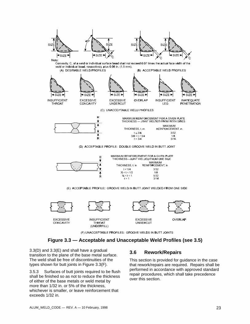
3.5.1 The faces of fillet welds may be slightlyconvex, flat, or slightly concave as shown inFigures 3.3(A) and 3.3(B), with none of theunacceptable profiles shown in Figure 3.3(C).Except at outside corner joints, the convexity, C,of a weld or individual surface bead shall notexceed 0.07 times the actual face width of theweld or individual bead, respectively, plus 0.06 in.
3.5.2 Groove welds shall be made with slight orminimum reinforcement unless otherwisespecified. In the case of butt and corner joints,the weld reinforcement and melt-through heightshall not exceed the values listed in Figures
ALUM_WELD_CODE — REV. A — 10 February, 1998 23
Figure 3.3 — Acceptable and Unacceptable Weld Profiles (see 3.5)
3.3(D) and 3.3(E) and shall have a gradualtransition to the plane of the base metal surface.The weld shall be free of discontinuities of thetypes shown for butt joints in Figure 3.3(F).
3.5.3 Surfaces of butt joints required to be flushshall be finished so as not to reduce the thicknessof either of the base metals or weld metal bymore than 1/32 in. or 5% of the thickness,whichever is smaller, or leave reinforcement thatexceeds 1/32 in.
3.6 Rework/Repairs
This section is provided for guidance in the casethat rework/repairs are required. Repairs shall beperformed in accordance with approved standardrepair procedures, which shall take precedenceover this section.
ALUM_WELD_CODE — REV. A — 10 February, 1998 24
Definitions for rework and repair are as follows:
Rework – The removal and replacing of anexisting weld, addition or deletion of weldmetal to bring a weld to drawingrequirement, or the removal andreplacement of a mislocated component.
Repair – Through the welding process, therestoration of base metal to the correctconfiguration. This includes mislocatedholes, slots, undersize and oversizeconditions.
3.6.1 The removal of weld metal or portions ofthe base metal may be done in accordance withsection 3.2.6. The removal shall be done so thatthe remaining weld metal and base metal are notnicked or undercut. Unacceptable portions of theweld shall be removed without substantialremoval of base metal. Metal added tocompensate for any deficiency in the size of theweld shall be deposited by a qualified welder withfiller of the same composition in accordance withan approved welding procedure The surfacesshall be cleaned thoroughly before welding.
3.6.2 The contractor has the option of eitherreworking an unacceptable weld, or removing andreplacing the entire weld, except as required bysection 3.6.3. If the contractor elects to reworkthe weld, it shall be corrected as follows:
3.6.2.1 Overlap or Excessive Convexity.Excess weld metal shall be removed bymachining, chipping, or grinding.
3.6.2.2 Excessive Concavity of Weld orCrater, Under-size Welds, Undercutting.Surfaces shall be prepared and additional weldmetal deposited in accordance with the specifiedwelding procedure.
3.6.2.3 Excessive Weld Porosity orIncomplete Fusion. Unacceptable portions shallbe removed and the area rewelded in accordancewith the specified welding procedure.
3.6.2.4 Cracks in Weld or Base Metal. Theextent of the crack shall be ascertained by use ofvisual, or by dye penetrant, X-ray examination, orother NDT means. The crack shall be removedand the area rewelded in accordance with thespecified welding procedure, as required insections 8, 9, or 10. If dye penetrant is used, alltraces of penetrant and developer shall beremoved before rewelding is begun.
3.6.3 If the contractor elects to remove andreplace the entire weld, the procedure approvedfor use on the original weld shall be used andsuch replacement welds shall be recorded.
3.6.4 The reworked or replaced weld shall betested or examined by the method originally usedand the same technique and quality acceptancecriteria shall be applied.
3.6.5 Members distorted by welding shall bestraightened at ambient temperature bymechanical means. If localized heating is to beapplied in any straightening operation, thecomplete procedure shall be approved by theGovernment.
3.6.6 Approval of the Weld or Quality Engineeror of Production supervision shall be obtained forsuch corrections as weld repairs to mill defects inthe base metal and repair of cracks in accordancewith approved repair procedures.
3.6.7 Production Supervision shall be notifiedbefore improperly fitted and tacked members arecut apart.
3.6.8 If, after an unacceptable weld has beenmade, work is performed which has rendered thatweld inaccessible or has created new conditionswhich make correction of the unacceptable welddangerous or ineffective, then the originalconditions shall be restored by removing theadded welds or members, or both, before thecorrections are made. If this is not done, the weldmust be submitted to MRB for disposition.
3.7 Cleaning Of Completed Welds
3.7.1 Welded joints shall not be painted orotherwise covered before the welding is examinedand approved.
3.7.2 Weld spatter shall be removed only whenits presence affects subsequent component fit, orwhere on the finished product it results in apotential personnel safety hazard.
Footnotes:
1 The requirements of 3.2.4 are not applicable to cases inwhich the stress is applied normal to the plate surface.
2 Backing to prevent melt-through may be of ceramic glasstape, austenitic stainless steel or an alloy with the M-numberclassification of the base metal. The backing shall be inintimate contact with the root side of the components beingwelded. If aluminum alloy backing is to be left permanentlyin place, it may be attached by continuous fillet welds.
ALUM_WELD_CODE — REV. A — 10 February, 1998 25
4. Technique
Part A
General Requirements for Gas MetalArc, Gas Tungsten Arc and Plasma
Arc (Variable Polarity) Welding
4.1 Material Requirements
4.1.1 The Filler metal shall comply with all therequirements set forth in the latest edition ofANSI/AWS A5.10, Specification for BareAluminum and Aluminum Alloy WeldingElectrodes and Rods. (Note: When required, thefiller metal must have the capability of meetingradiographic soundness requirements.)
4.1.2 Filler metal alloys to be used with specificbase metals and combinations of, base metalsshall be as shown in Table 1.2.
4.1.3 The filler metals used shall conform toANSI/AWS A5.10. The contractor ormanufacturer shall have a method of verification(purchase orders, packing slips, etc.) thatprovides evidence the filler metals conforms toANSI/AWS A5.10.
4.2 Welding Processes
The welding process shall be either gas metal arc(GMAW), pulsed gas metal arc (GMAW-P), gastungsten arc (GTAW), plasma arc with variablepolarity (PAW-VP), automatic gas metal arc(GMAW-AU), mechanized gas metal arc (GMAW-ME), or robotic gas metal arc (GMAW-RO).
4.3 Shielding Gases
4.3.1 Argon, helium, or mixtures of argon andhelium used for shielding shall be a welding gradehaving a dew point of -63° F or lower.
4.3.2 The contractor or manufacturer shallmaintain records of the gas manufacturer'scertification that the gas or gas mixture is suitablefor the intended application and conforms to thedew point required in 4.3.1.
4.4 Preheat Requirements
Preheating is sometimes used for welding thickaluminum sections to avoid cold-start defects, toachieve heat balance with dissimilar thicknesses,or to remove moisture. Special care shall betaken to ensure close temperature control,
particularly when fabricating the heat treatablealuminum alloys and the 5000 series aluminumalloys containing more than 3% magnesium.Preheating temperatures for these types of alloysshall not exceed 250° F. Holding times at thistemperature shall not exceed 15 minutes.
4.5 Interpass TemperatureRequirements
When fabricating the heat treatable aluminumalloys and the 5000 series alloys containing morethan 3% magnesium, interpass temperatures shallnot exceed 275° F to provide optimum weldproperties and to decrease the possibility ofsensitization to exfoliation and stress corrosioncracking.
4.6 Arc Strikes
Arc strikes outside the area of permanent weldsshould be avoided on any base metal. Blemishescaused by arc strikes shall be finished to asmooth contour when their presence affects form,fit, or function, and checked to ensure no loss ofsoundness of the base metal. Cracks caused byarc strikes shall be removed. The cracks shall berepair-welded and the weld finished flush with themetal surface.
4.7 Cleaning Prior to Welding
All joint faces and the surfaces adjacent to thearea to be welded shall be prepared inaccordance with 3.2.8.
4.8 Weld Termination
4.8.1 Welds shall be started and stopped in amanner that ensures sound welds. Wheneverpossible and appropriate, the starting andstopping shall be done by the use of extensionbars or run-on and run-off plates.
4.8.2 Extension bars or run-on and run-offplates shall be removed (preferably bymechanical cutting) upon completion and coolingof the weld. The ends of the weld shall be madesmooth and fit flush with the edges of theadjacent parts.
4.8.3 When it is impossible to terminate a weldon an extension bar or run-on or run-off plate,prior consideration to weld termination should begiven so as to terminate the weld in a low stressarea.
ALUM_WELD_CODE — REV. A — 10 February, 1998 26
4.8.4 The techniques for terminating a filletweld or a cover pass bead within a joint shouldconsist of the following, or any combination of thefollowing:
(1) Reversing the direction of travel for aminimum distance of 2 in.
(2) Increasing travel speed to reduce cratersize.
(3) Providing suitable weld build-up with theweld surface.
(4) Tail-in and tail-out.
4.8.5 Crater cracks existing in tack welds thatwill be incorporated into final welds, extension offillet welds, and within intermediate or root passesof root welds, shall be removed by mechanicalmeans prior to additional welding.
4.9 Backing to Prevent MeltingThrough
4.9.1 Permanent backing for groove welds shallbe of aluminum of the same M-Number as thebase metal. Permanent backing shall not be usedwhen the root opening exceeds 3/8 in.
4.9.2 Backing shall be made continuous for thefull length of the weld. All welds in the backingshall be complete joint penetration groove weldswith the reinforcement ground smooth. Thesewelds shall meet the workmanship requirementsof section 3 of this Code.
4.9.3 Permanent backing in all weld repairsneed not be removed unless specified on thedrawing or required by MRB disposition.
4.9.4 Temporary backing for groove welds maybe of austenitic stainless steel, glass tape,ceramic, or aluminum (3XXX, 5XXX, 6XXX).Copper shall not be used as a temporary backingbecause of the dangers of weld contaminationand corrosion problems.
4.10 Peening
Weld peening may be used only when permittedon the drawing.
4.11 Thermal Stress-Relief Treatment
4.11.1 Where required by contract documents,welded assemblies shall be stress relieved bythermal treatment. Specific thermal practicesshould be determined for each alloy and temperconsidered for stress relief. Finish machiningshall preferably be done after stress relief.
4.11.2 The stress relief treatment procedureshall be as stipulated on the drawing and shallconform to the following requirements:
(1) The temperature of the furnace shall notexceed 200° F at the time the weldedassembly is placed in it.
(2) The maximum temperature developed inany part of the assembly and the exposuretime shall not exceed the drawingrequirements.
(3) During the heating period, the variation intemperature throughout the weldment shallbe no greater than 100° F within any 15 ftinterval of length.
Part B
Gas Metal Arc Welding
4.12 General
This part covers specific requirements for gasmetal arc welding in the solid state and pulsedmodes, in addition to requirements of Part A ofthis section.
4.13 Restrictions on Gas Metal ArcWelding with Single Electrode
4.13.1 The following are restrictions on thewelding procedures:
4.13.1.1 Except for mechanized high currentdensity or automated welding, the maximum sizeof a stringer bead fillet weld made in one passshall be 3/8 in. for all welding positions.
For heat treatable aluminum alloys that are to bepostweld precipitation-age-hardened only, themaximum size of stringer bead fillet welds madein one pass shall be 5/16 in. for all weldingpositions.
4.13.1.2 Except for mechanized high currentdensity or automated welding, the thickness ofweld layers, except root and surface layers, shallnot exceed 3/8 in. When the root opening of agroove weld exceeds 3/8 in., a multiple pass split-layer technique shall be used. The split-layertechnique shall also be used in making allmultiple pass welds when the width of the layerexceeds 1¼ in.
4.13.1.3 The welding current, voltage, gasflow, filler metal diameter and travel speed shallbe in compliance with qualified PQRs/WPSs and
ALUM_WELD_CODE — REV. A — 10 February, 1998 27
the requirements of section 8, 9, or 10, asapplicable.
4.13.1.4 The progression of all passes ofvertical position welding shall be upwards.
4,13.1.5 Welding shall employ only theforehand technique
4.13.2 Except as noted in section 10, completejoint penetration groove welds made without theuse of backing shall have the root of the initialpass backgouged, chipped, or otherwise removedto sound metal and all trace of root discontinuityshall be eliminated before welding is started onthe second side.
4.13.3 Gas metal arc welding shall not be donein a draft or wind. Where drafty conditions exist,a windbreak or shelter shall be employed.
4.13.4 Copper inclusions deposited duringmeltback time (burnback) shall be gouged,chipped, or otherwise removed to sound metal.
Part C
Gas Tungsten Arc Welding
4.14 General
This part covers specific requirements for gastungsten arc welding in addition to therequirements of Part A of this section.
4.15 Tungsten Electrodes
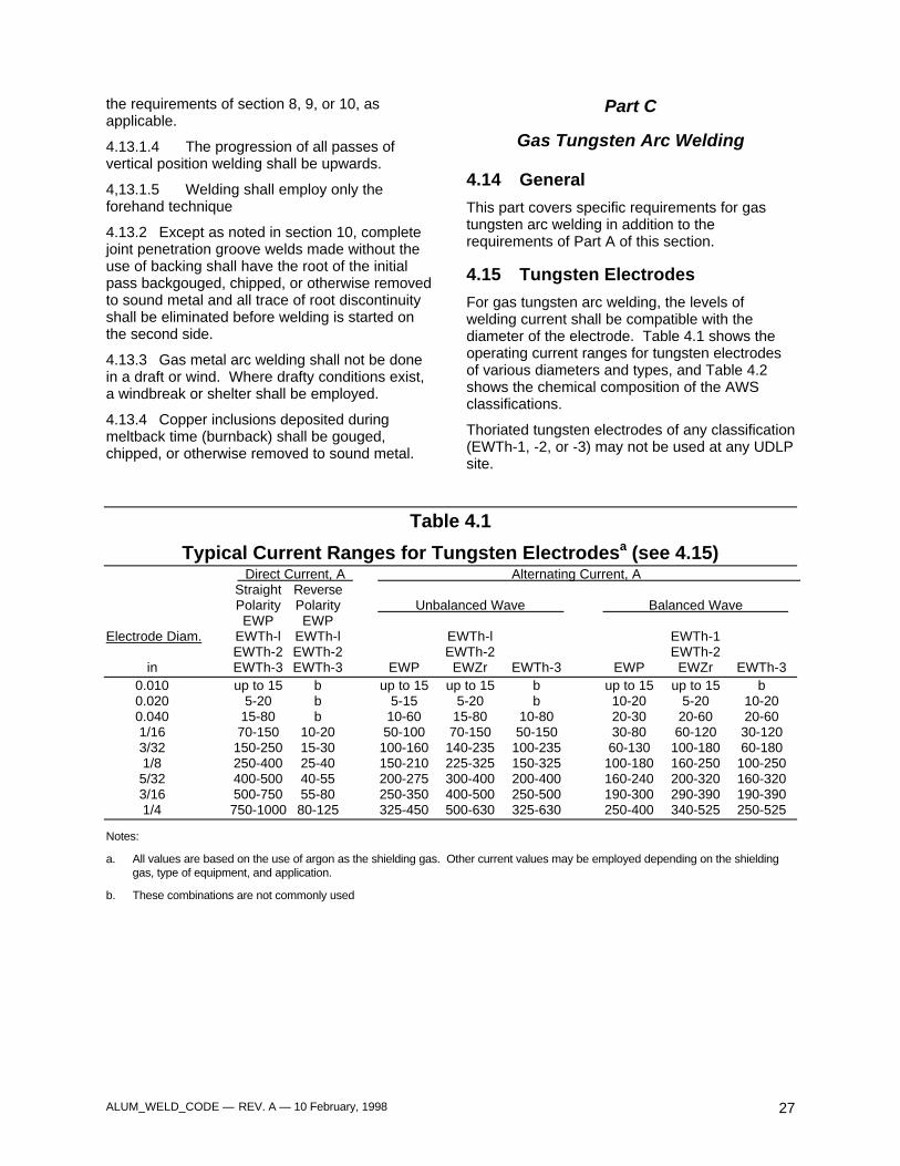
For gas tungsten arc welding, the levels ofwelding current shall be compatible with thediameter of the electrode. Table 4.1 shows theoperating current ranges for tungsten electrodesof various diameters and types, and Table 4.2shows the chemical composition of the AWSclassifications.
Thoriated tungsten electrodes of any classification(EWTh-1, -2, or -3) may not be used at any UDLPsite.
Table 4.1
Typical Current Ranges for Tungsten Electrodesa (see 4.15) Direct Current, A Alternating Current, A Straight ReversePolarity Polarity Unbalanced Wave Balanced Wave EWP EWP
Electrode Diam. EWTh-l EWTh-l EWTh-l EWTh-1EWTh-2 EWTh-2 EWTh-2 EWTh-2
in EWTh-3 EWTh-3 EWP EWZr EWTh-3 EWP EWZr EWTh-30.010 up to 15 b up to 15 up to 15 b up to 15 up to 15 b0.020 5-20 b 5-15 5-20 b 10-20 5-20 10-200.040 15-80 b 10-60 15-80 10-80 20-30 20-60 20-601/16 70-150 10-20 50-100 70-150 50-150 30-80 60-120 30-1203/32 150-250 15-30 100-160 140-235 100-235 60-130 100-180 60-1801/8 250-400 25-40 150-210 225-325 150-325 100-180 160-250 100-2505/32 400-500 40-55 200-275 300-400 200-400 160-240 200-320 160-3203/16 500-750 55-80 250-350 400-500 250-500 190-300 290-390 190-3901/4 750-1000 80-125 325-450 500-630 325-630 250-400 340-525 250-525
Notes:
a. All values are based on the use of argon as the shielding gas. Other current values may be employed depending on the shieldinggas, type of equipment, and application.
b. These combinations are not commonly used
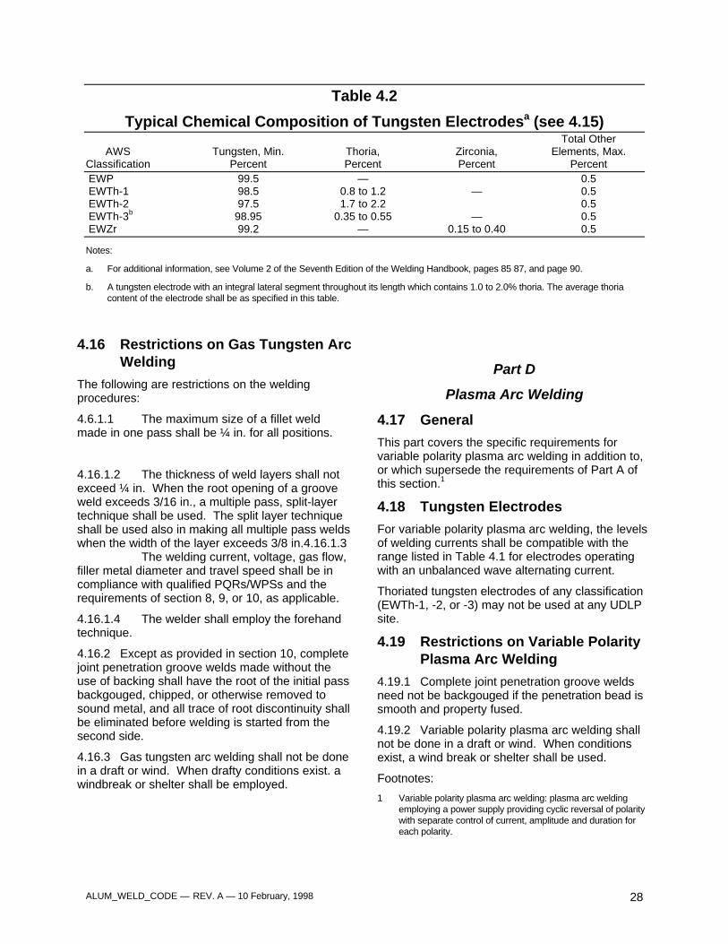
ALUM_WELD_CODE — REV. A — 10 February, 1998 28
Table 4.2
Typical Chemical Composition of Tungsten Electrodesa (see 4.15)Total Other
AWS Tungsten, Min. Thoria, Zirconia, Elements, Max.Classification Percent Percent Percent PercentEWP 99.5 — 0.5EWTh-1 98.5 0.8 to 1.2 — 0.5EWTh-2 97.5 1.7 to 2.2 0.5EWTh-3b 98.95 0.35 to 0.55 — 0.5EWZr 99.2 — 0.15 to 0.40 0.5
Notes:
a. For additional information, see Volume 2 of the Seventh Edition of the Welding Handbook, pages 85 87, and page 90.
b. A tungsten electrode with an integral lateral segment throughout its length which contains 1.0 to 2.0% thoria. The average thoriacontent of the electrode shall be as specified in this table.
4.16 Restrictions on Gas Tungsten ArcWelding
The following are restrictions on the weldingprocedures:
4.6.1.1 The maximum size of a fillet weldmade in one pass shall be ¼ in. for all positions.
4.16.1.2 The thickness of weld layers shall notexceed ¼ in. When the root opening of a grooveweld exceeds 3/16 in., a multiple pass, split-layertechnique shall be used. The split layer techniqueshall be used also in making all multiple pass weldswhen the width of the layer exceeds 3/8 in.4.16.1.3
The welding current, voltage, gas flow,filler metal diameter and travel speed shall be incompliance with qualified PQRs/WPSs and therequirements of section 8, 9, or 10, as applicable.
4.16.1.4 The welder shall employ the forehandtechnique.
4.16.2 Except as provided in section 10, completejoint penetration groove welds made without theuse of backing shall have the root of the initial passbackgouged, chipped, or otherwise removed tosound metal, and all trace of root discontinuity shallbe eliminated before welding is started from thesecond side.
4.16.3 Gas tungsten arc welding shall not be donein a draft or wind. When drafty conditions exist. awindbreak or shelter shall be employed.
Part D
Plasma Arc Welding
4.17 General
This part covers the specific requirements forvariable polarity plasma arc welding in addition to,or which supersede the requirements of Part A ofthis section.1
4.18 Tungsten Electrodes
For variable polarity plasma arc welding, the levelsof welding currents shall be compatible with therange listed in Table 4.1 for electrodes operatingwith an unbalanced wave alternating current.
Thoriated tungsten electrodes of any classification(EWTh-1, -2, or -3) may not be used at any UDLPsite.
4.19 Restrictions on Variable PolarityPlasma Arc Welding
4.19.1 Complete joint penetration groove weldsneed not be backgouged if the penetration bead issmooth and property fused.
4.19.2 Variable polarity plasma arc welding shallnot be done in a draft or wind. When conditionsexist, a wind break or shelter shall be used.
Footnotes:
1 Variable polarity plasma arc welding: plasma arc weldingemploying a power supply providing cyclic reversal of polaritywith separate control of current, amplitude and duration foreach polarity.
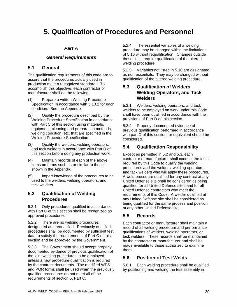
ALUM_WELD_CODE — REV. A — 10 February, 1998 29
5. Qualification of Procedures and Personnel
Part A
General Requirements
5.1 General
The qualification requirements of this code are toassure that the procedures actually used inproduction meet a recognized standard.1 Toaccomplish this objective, each contractor ormanufacturer shall do the following:
(1) Prepare a written Welding ProcedureSpecification In accordance with 5.13.2 for eachcondition. See the Appendix.
(2) Qualify the procedure described by theWelding Procedure Specification in accordancewith Part C of this section using materials,equipment, cleaning and preparation methods,welding condition, etc. that are specified in theWelding Procedure Specification.
(3) Qualify the welders, welding operators,and tack welders in accordance with Part D ofthis section before doing any production work.
(4) Maintain records of each of the aboveitems on forms such as or similar to thoseshown in the Appendix.
(5) Impart knowledge of the procedures to beused to the welders, welding operators, andtack welders
5.2 Qualification of WeldingProcedures
5.2.1 Only procedures qualified in accordancewith Part C of this section shall be recognized asapproved procedures.
5.2.2 There are no welding proceduresdesignated as prequalified. Previously qualifiedprocedures shall be documented by sufficient testdata to satisfy the requirements of Part C of thissection and be approved by the Government.
5.2.3 The Government should accept properlydocumented evidence of previous qualification ofthe joint welding procedures to be employed,unless a new procedure qualification is requiredby the contract documents. The modified WPSand PQR forms shall be used when the previouslyqualified procedures do not meet all of therequirements of section 5, Part C.
5.2.4 The essential variables of a weldingprocedure may be changed within the limitationsof 5.16 without requalification. Changes outsidethese limits require qualification of the alteredwelding procedure.
5.2.5 Variables not listed in 5.16 are designatedas non-essentials. They may be changed withoutqualification of the altered welding procedure.
5.3 Qualification of Welders,Welding Operators, and TackWelders
5.3.1 Welders, welding operators, and tackwelders to be employed on work under this Codeshall have been qualified in accordance with theprovisions of Part D of this section.
5.3.2 Properly documented evidence ofprevious qualification performed in accordancewith part D of this section, or equivalent should beconsidered.
5.4 Qualification Responsibility
Except as permitted in 5.2 and 5.3, eachcontractor or manufacturer shall conduct the testsrequired by this Code to qualify the weldingprocedures and the welders, welding operators,and tack welders who will apply these procedures.A weld procedure qualified for any contract at anyUnited Defense site shall be considered as beingqualified for all United Defense sites and for allUnited Defense contractors who meet therequirements of this Code. A welder qualified atany United Defense site shall be considered asbeing qualified for the same process and positionat any other United Defense site.
5.5 Records
Each contractor or manufacturer shall maintain arecord of all welding procedure and performancequalifications of welders, welding operators, ortack welders. These records shall be maintainedby the contractor or manufacturer and shall bemade available to those authorized to examinethem.
5.6 Position of Test Welds
5.6.1 Each welding procedure shall be qualifiedby positioning and welding the test assembly in

ALUM_WELD_CODE — REV. A — 10 February, 1998 30
Tabulations of positions of groove welds
PositionDiagram
ReferenceInclination
of AxisRotation of
FaceFlat A 0° 150° to 210°
Horizontal B 0° to 15° 80° to 150°210° to 280°
Overhead C 0° to 80° 0° to 80°280° to 360°
Vertical DE
15° to 80°80° to 90°
80° to 280°0° to 360°
Notes:1. The horizontal reference plane is always taken to lie below the weld under consideration.2. The inclination of axis is measured from the horizontal reference plane toward the vertical reference plane.3. The angle of rotation of the face is determined by a line perpendicular to the theoretical face of the weld which passes through the
axis of the weld. The reference position (0°) of rotation of the face invariably points in the direction opposite to that in which the axisangle increases. When looking at point P, the angle of rotation of the face of the weld is measured in a clockwise direction from thereference position (0°).
Figure 5.1 — Positions of Groove Welds (see 5.6.1)
the manner stated below for the position for whichit is to be qualified. These positions are classified
as: (1) flat, (2) horizontal, (3) vertical, or (4)overhead in accordance with Figures 5.1 and 5.2.
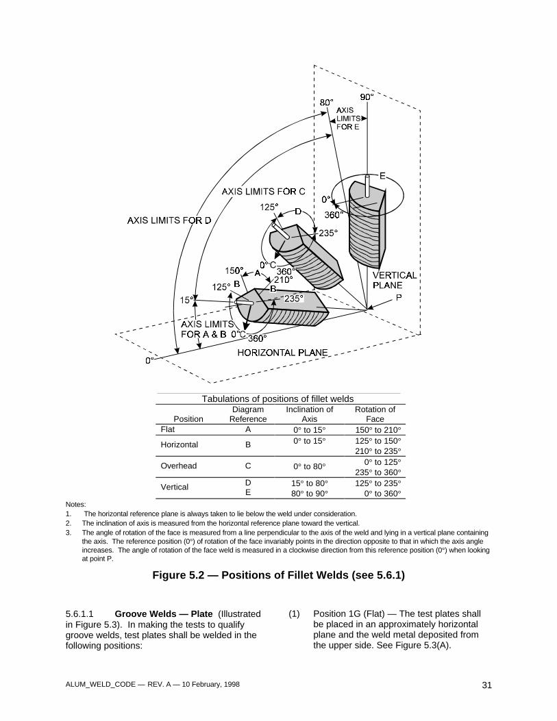
ALUM_WELD_CODE — REV. A — 10 February, 1998 31
Tabulations of positions of fillet welds
PositionDiagram
ReferenceInclination of
AxisRotation of
FaceFlat A 0° to 15° 150° to 210°
Horizontal B 0° to 15° 125° to 150°210° to 235°
Overhead C 0° to 80° 0° to 125°235° to 360°
Vertical DE
15° to 80°80° to 90°
125° to 235°0° to 360°
Notes:1. The horizontal reference plane is always taken to lie below the weld under consideration.2. The inclination of axis is measured from the horizontal reference plane toward the vertical.3. The angle of rotation of the face is measured from a line perpendicular to the axis of the weld and lying in a vertical plane containing
the axis. The reference position (0°) of rotation of the face invariably points in the direction opposite to that in which the axis angleincreases. The angle of rotation of the face weld is measured in a clockwise direction from this reference position (0°) when lookingat point P.
Figure 5.2 — Positions of Fillet Welds (see 5.6.1)
5.6.1.1 Groove Welds — Plate (Illustratedin Figure 5.3). In making the tests to qualifygroove welds, test plates shall be welded in thefollowing positions:
(1) Position 1G (Flat) — The test plates shallbe placed in an approximately horizontalplane and the weld metal deposited fromthe upper side. See Figure 5.3(A).
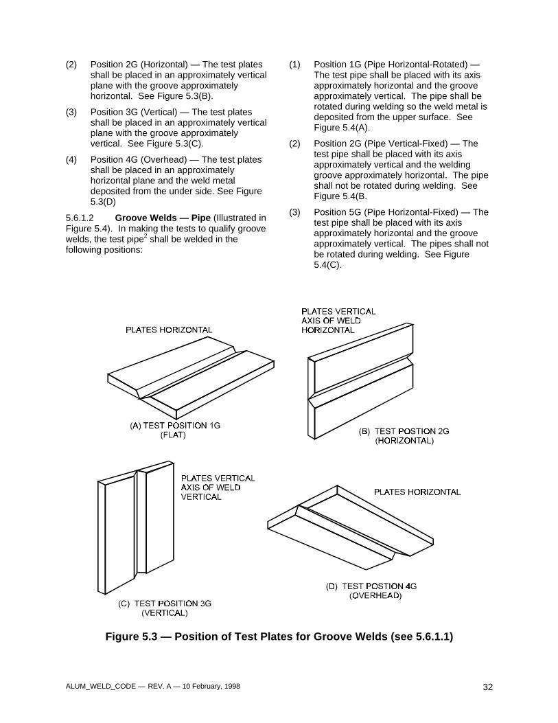
ALUM_WELD_CODE — REV. A — 10 February, 1998 32
(2) Position 2G (Horizontal) — The test platesshall be placed in an approximately verticalplane with the groove approximatelyhorizontal. See Figure 5.3(B).
(3) Position 3G (Vertical) — The test platesshall be placed in an approximately verticalplane with the groove approximatelyvertical. See Figure 5.3(C).
(4) Position 4G (Overhead) — The test platesshall be placed in an approximatelyhorizontal plane and the weld metaldeposited from the under side. See Figure5.3(D)
5.6.1.2 Groove Welds — Pipe (Illustrated inFigure 5.4). In making the tests to qualify groovewelds, the test pipe2 shall be welded in thefollowing positions:
(1) Position 1G (Pipe Horizontal-Rotated) —The test pipe shall be placed with its axisapproximately horizontal and the grooveapproximately vertical. The pipe shall berotated during welding so the weld metal isdeposited from the upper surface. SeeFigure 5.4(A).
(2) Position 2G (Pipe Vertical-Fixed) — Thetest pipe shall be placed with its axisapproximately vertical and the weldinggroove approximately horizontal. The pipeshall not be rotated during welding. SeeFigure 5.4(B.
(3) Position 5G (Pipe Horizontal-Fixed) — Thetest pipe shall be placed with its axisapproximately horizontal and the grooveapproximately vertical. The pipes shall notbe rotated during welding. See Figure5.4(C).
Figure 5.3 — Position of Test Plates for Groove Welds (see 5.6.1.1)
ALUM_WELD_CODE — REV. A — 10 February, 1998 33
Figure 5.4 — Position of Test Plate for Groove Welds (see 5.6.1.2)
(4) Position 6G (Pipe Inclined-Fixed) — Thetest pipe shall be inclined at approximately45° with the horizontal. The pipe shall notbe rotated during welding. See Figure5.4(D).
(5) Position 6GR (Restricted, Pipe Inclined-Fixed.) — Test for complete jointpenetration groove welds of tubular T-, Y-and K-connections.
The test pipe shall be provided with arestriction ring and be inclined atapproximately 45° with the horizontal. Thepipe shall not be rotated during welding.See Figure 5.4(E).
5.6.1.3 Fillet Welds — Plate (Illustrated inFigure 5.5). In making the tests to qualify weldson plate, test plates shall be welded in thepositions outlined below:
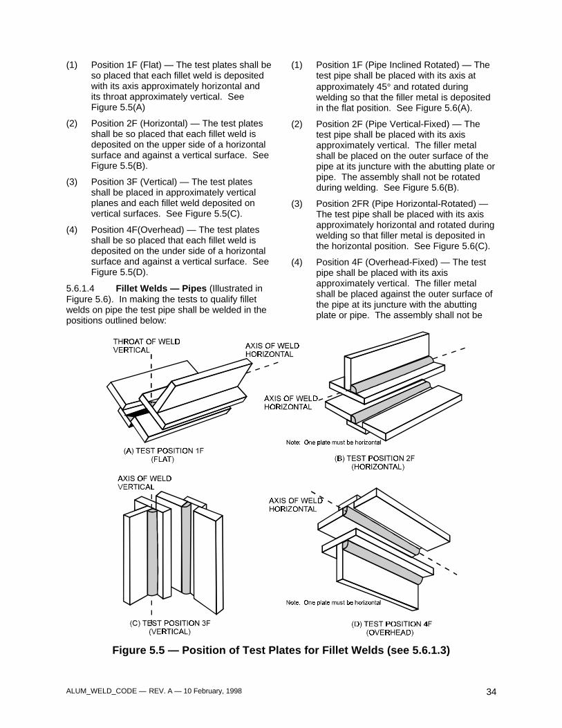
ALUM_WELD_CODE — REV. A — 10 February, 1998 34
(1) Position 1F (Flat) — The test plates shall beso placed that each fillet weld is depositedwith its axis approximately horizontal andits throat approximately vertical. SeeFigure 5.5(A)
(2) Position 2F (Horizontal) — The test platesshall be so placed that each fillet weld isdeposited on the upper side of a horizontalsurface and against a vertical surface. SeeFigure 5.5(B).
(3) Position 3F (Vertical) — The test platesshall be placed in approximately verticalplanes and each fillet weld deposited onvertical surfaces. See Figure 5.5(C).
(4) Position 4F(Overhead) — The test platesshall be so placed that each fillet weld isdeposited on the under side of a horizontalsurface and against a vertical surface. SeeFigure 5.5(D).
5.6.1.4 Fillet Welds — Pipes (Illustrated inFigure 5.6). In making the tests to qualify filletwelds on pipe the test pipe shall be welded in thepositions outlined below:
(1) Position 1F (Pipe Inclined Rotated) — Thetest pipe shall be placed with its axis atapproximately 45° and rotated duringwelding so that the filler metal is depositedin the flat position. See Figure 5.6(A).
(2) Position 2F (Pipe Vertical-Fixed) — Thetest pipe shall be placed with its axisapproximately vertical. The filler metalshall be placed on the outer surface of thepipe at its juncture with the abutting plate orpipe. The assembly shall not be rotatedduring welding. See Figure 5.6(B).
(3) Position 2FR (Pipe Horizontal-Rotated) —The test pipe shall be placed with its axisapproximately horizontal and rotated duringwelding so that filler metal is deposited inthe horizontal position. See Figure 5.6(C).
(4) Position 4F (Overhead-Fixed) — The testpipe shall be placed with its axisapproximately vertical. The filler metalshall be placed against the outer surface ofthe pipe at its juncture with the abuttingplate or pipe. The assembly shall not be
Figure 5.5 — Position of Test Plates for Fillet Welds (see 5.6.1.3)
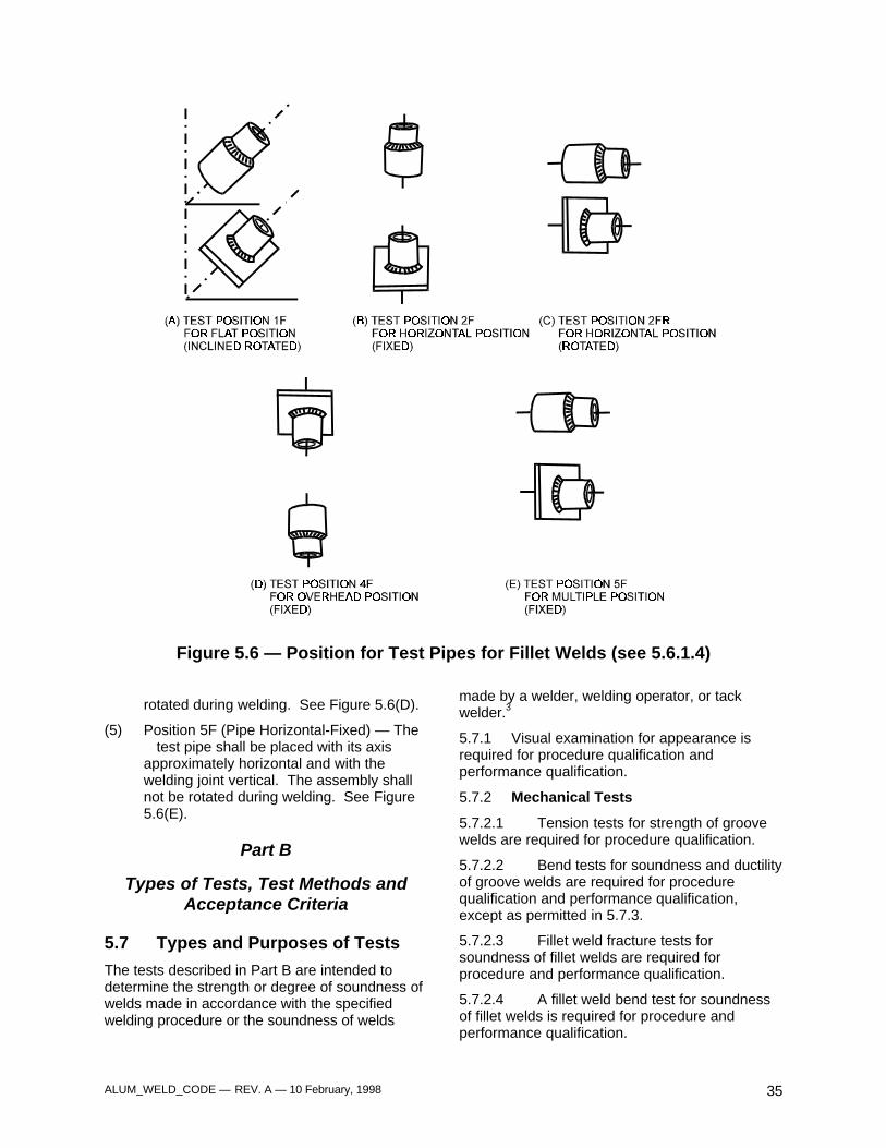
ALUM_WELD_CODE — REV. A — 10 February, 1998 35
Figure 5.6 — Position for Test Pipes for Fillet Welds (see 5.6.1.4)
rotated during welding. See Figure 5.6(D).
(5) Position 5F (Pipe Horizontal-Fixed) — Thetest pipe shall be placed with its axis
approximately horizontal and with thewelding joint vertical. The assembly shallnot be rotated during welding. See Figure5.6(E).
Part B
Types of Tests, Test Methods andAcceptance Criteria
5.7 Types and Purposes of Tests
The tests described in Part B are intended todetermine the strength or degree of soundness ofwelds made in accordance with the specifiedwelding procedure or the soundness of welds
made by a welder, welding operator, or tackwelder.3
5.7.1 Visual examination for appearance isrequired for procedure qualification andperformance qualification.
5.7.2 Mechanical Tests
5.7.2.1 Tension tests for strength of groovewelds are required for procedure qualification.
5.7.2.2 Bend tests for soundness and ductilityof groove welds are required for procedurequalification and performance qualification,except as permitted in 5.7.3.
5.7.2.3 Fillet weld fracture tests forsoundness of fillet welds are required forprocedure and performance qualification.
5.7.2.4 A fillet weld bend test for soundnessof fillet welds is required for procedure andperformance qualification.
ALUM_WELD_CODE — REV. A — 10 February, 1998 36
5.7.3 Radiographic examination may be usedin lieu of bend tests for performance qualificationof welded groove joints in wrought materials. Theradiographic procedure and technique shall be inaccordance with the requirements of section 6,Part B of this Code.
5.8 Visual Examination
5.8.1 Examination Procedure. Visualinspection of the weld surface shall be performedon the test weldment prior to cutting anymechanical test specimens except thatmacroetching of cut sections is included in theexamination of fillet welds and partial penetrationgroove welds. Liquid penetrants, magnifyinglenses, scales or templates may be used as aidsin determining whether the sample weldmentpasses the criteria outlined in 5.8.2 or 5.8.3.
5.8.1.1 For detecting discontinuities that areopen to the surface, liquid penetrant inspectionmay be used. The methods set forth in ASTME165, Standard Recommended Practice for LiquidPenetrant Inspection Method, shall be used andthe standards of acceptance shall be inaccordance with 8.7.1, 9.7.1, or 10.8.1, whicheveris applicable.
5.8.1.2 The macroetched specimen for thefillet weld test assembly or the partial penetrationgroove weld test assembly shall be taken fromthe end of the sample weldment. The macroetchspecimens for fillet welded pipe, tubing, or castinggroove welded assemblies shall be taken bysectioning longitudinally through the center of thepipe, tubing, or casting. One cut face of thespecimen shall be smoothed and etched with asuitable etchant to give a clear definition of theweld metal and heat-affected zone.
5.8.2 Acceptance Criteria — VisualExamination — Groove Welds, Plate and Pipe.Unless the test weldment passes the followingvisual examination, the test shall have failed:
(1) Both the face and root surfaces shall befree of cracks.
(2) All craters shall be filled to the full crosssection of the weld.
(3) The edges of the weld shall blend smoothlywith the base metal.
(4) Underfill shall not exceed 0.01 in.
(5) The root shall show (a) complete fusion forfull penetration welds, or (b) penetrationequal to or greater than the weld size forpartial penetration welds.
(6) The maximum melt-through on groovewelds in pipe or tubing shall not exceed 1/8in.
(7) The root concavity shall not exceed 1/16 in.
(8) Total weld thickness shall be equal to orgreater than the thickness of the basemetal, but the weld reinforcement shall notexceed the following:
Thickness, tMaximum
Reinforcementin. in.
t ≤ 3/8 3/323/8 < t ≤ 3/4 1/8
t > 3/4 3/16
5.8.3 Acceptance Criteria — VisualExamination of Fillet Welds for Plate or Pipe.Unless the test weldment passes the visualexamination as follows, the test shall have failed:
(1) The surface of the weld shall be free fromcracks.
(2) All craters shall be filled to the full cross-section of the weld.
(3) The edges of the weld shall blend smoothlywith the base metal.
(4) Underfill shall not exceed 0.01 in.
(5) The leg lengths shall meet the requirementsof the procedure specification.
(6) The weld shall exhibit complete fusion inthe root and to the base metal by themacroetch test.
5.9 Tension Tests — Groove Welds
5.9.1 Specimens. Tension test specimensshall conform to one of the types illustrated inFigures 5.7, 5.9 or 5.10.
5.9.1.1 Reduced Section Test Specimens— Plate. Reduced section specimens from plateconforming to the requirements given in Figure5.7 shall be used for tension tests on allthicknesses of plate.
(1) A single specimen of full plate thicknessshall be used for thicknesses up to andincluding 1 in.
(2) For plate thicknesses greater than 1 in.,single or multiple specimens may be used.
(3) When multiple specimens are necessarybecause of the limitations of the testingequipment, the entire thickness shall be cut
ALUM_WELD_CODE — REV. A — 10 February, 1998 37
mechanically into the minimum number ofapproximately equal slices of a thicknessthat can be tested in the availableequipment. Each specimen (slice) shall betested, and collectively shall represent asingle required tension test.
5.9.1.2 Reduced Section Test Specimens— Pipe
(1) For pipe having an outside diameter greaterthan 3 in., reduced section specimensconforming to the requirements given inFigure 5.7 shall be used for tension tests onall thicknesses.
(a) A single specimen of the full thicknessshall be used for thicknesses up to andincluding 1 in.
(b) For thicknesses greater than 1 in.,single or multiple specimens may beused.
(c) When multiple specimens arenecessary because of the limitations ofthe testing equipment, the entirethickness shall be cut mechanically intothe minimum number of approximatelyequal slices of a thickness that can betested in the available equipment.Each specimen (slice) shall be testedand collectively shall represent a singlerequired tension test.
(2) For pipe having an outside diameter of 3 in.or less, test specimens conforming to therequirements given in Figure 5.9 may beused for tension tests.
5.9.1.3 Full-Section Pipe. For pipe havingan outside diameter of 3 in. or less, full-sectionspecimens conforming to the requirements givenin Figure 5.10 may be used for tension tests.
5.9.1.4 Partial Joint Penetration GrooveWelds — Plate and Pipe. For partial jointpenetration groove welds in plate and pipe, theexcess material on the root side of the joint shallbe removed by machining to the thickness of theweld size. Tension test specimens shall beprepared in accordance with 5.9.1.
5.9.2 Tension Test Procedure. Each tensiontest specimen shall be ruptured under tensile loadand the maximum load shall be determined. Thetensile strength shall be computed by dividing themaximum load by the least cross sectional areaof the specimen as determined frommeasurements made before the load was applied.
5.9.3 Acceptance criteria — Tension Tests— Plate and Pipe
5.9.3.1 The tensile strength shall be no lessthan the applicable requirement in Table 5.1.When multiple specimens are used, as allowed in5.9.1.1 and 5.9.1.2, each specimen (slice) shallmeet the requirement.
5.9.3.2 If base metals of different tensilestrengths are used, the specified minimum tensilestrength of the weaker of the two, as shown inTable 5.1, applies.
5.10 Bend Tests — Groove Welds —Plate and Pipe
5.10.1 Specimens. Except as allowed in 5.7.3,bend test specimens shall be prepared by cuttingthe test weldment to form specimens ofapproximately rectangular cross sectionconforming to one of the types shown in Figures5.11, 5.12, or 5.13. The cut surfaces shall bedesignated the sides of the specimen. Theoriginal surfaces of the specimen shall be calledthe face and root surfaces, the face surfacehaving the greater width of weld. Bendspecimens are of five types, depending onwhether the axis of the weld is transverse orparallel to the longitudinal axis of the specimenand which surface (side, face, or root) is on theconvex (outer) side of the bent specimen.Longitudinal bend specimens may be used in lieuof transverse bend specimens for testingcombinations of base and filler materials whichdiffer markedly in bending properties.
5.10.1.1 Transverse Side Bend Specimen.The weld is transverse to the longitudinal axis ofthe specimen which is bent so that the sidesurface with the larger discontinuity, if any,becomes the convex surface of the bendspecimen. Transverse side bend specimens shallconform to the dimensions shown in Figure 5.11.Specimens of base metal thickness greater than1.5 in. may be bent at full width or cut into an oddnumber of strips of approximately equal width sothat the axis of one interior strip coincides withroot of the weld. Each specimen (strip) shall betested and, collectively, shall represent a singlerequired bend test.
5.10.1.2 Transverse Face Bend Specimen.The weld is transverse to the longitudinal axis ofthe specimen which is bent so that the face
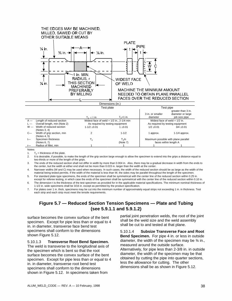
ALUM_WELD_CODE — REV. A — 10 February, 1998 38
Dimensions (in.)
Test plate Test pipe
Tp ≤ 1 in Tp>1 in.3 in. or smaller
diameter
greater than 3 in.diameter or large
job size pipeA — Length of reduced section Widest face of weld + 1/2 in., 2-1/4 min Widest face of weld + 1/2 in.L — Overall length, min (Note 2) As required by testing equipment As required by testing equipmentW — Width of reduced section
(Notes 3, 4)1-1/2 ±0.01 1 ±0.01 1/2 ±0.01 3/4 ±0.01
C— Width of grip section, min(Notes 4, 5)
2 1-1/2 1 approx. 1-1/4 approx.
t— Specimen thickness(Notes 6, 7)
Tp Tp/n(Note 7)
Maximum possible with plane parallelfaces within length A
r— Radius of fillet, min 1 1 1 1
Notes:1. Tp = thickness of the plate.2. It is desirable, if possible, to make the length of the grip section large enough to allow the specimen to extend into the grips a distance equal to
two-thirds or more of the length of the grips.3. The ends of the reduced section shall not differ in width by more than 0.004 in. Also, there may be a gradual decrease in width from the ends to
the center, but the width at either end shall not be more than 0.015 in. larger than the width at the center.4. Narrower widths (W and C) may be used when necessary. In such cases, the width of the reduced section should be as large as the width of the
material being tested permits. If the width of the material is less than W, the sides may be parallel throughout the length of the specimen.5. For standard plate-type specimens, the ends of the specimen shall be symmetrical with the center line of the reduced section within 0.25 in.
except for referee testing, in which case the ends of the specimen shall be symmetrical with the center line of the reduced section within 0.10 in.6. The dimension t is the thickness of the test specimen as provided for in the applicable material specifications. The minimum nominal thickness of
1-1/2 in. wide specimens shall be 3/16 in. except as permitted by the product specification.7. For plates over 1 in. thick, specimens may be cut into the minimum number of approximately equal strips not exceeding 1 in. in thickness. Test
each strip and each strip must meet the tensile requirements.
Figure 5.7 — Reduced Section Tension Specimens — Plate and Tubing(see 5.9.1.1 and 5.9.1.2)
surface becomes the convex surface of the bentspecimen. Except for pipe less than or equal to 4in. in diameter, transverse face bend testspecimens shall conform to the dimensionsshown Figure 5.12.
5.10.1.3 Transverse Root Bend Specimen.The weld is transverse to the longitudinal axis ofthe specimen which is bent so that the rootsurface becomes the convex surface of the bentspecimen. Except for pipe less than or equal to 4in. in diameter, transverse root bend testspecimens shall conform to the dimensionsshown in Figure 5.12. In specimens taken from
partial joint penetration welds, the root of the jointshall be the weld size and the weld assemblyshall be cut to and tested at that plane.
5.10.1.4 Subsize Transverse Face and RootBend Specimen. For pipe 4 in. or less in outsidediameter, the width of the specimen may be ¾ in.,measured around the outside surface.Alternatively, for pipe less than 2-3/8 in. in outsidediameter, the width of the specimen may be thatobtained by cutting the pipe into quarter sections,less the allowance for cutting. The otherdimensions shall be as shown in Figure 5.12.
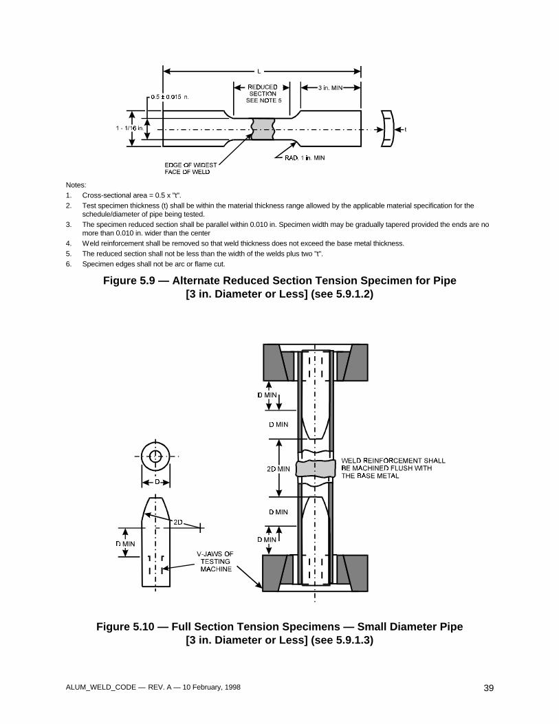
ALUM_WELD_CODE — REV. A — 10 February, 1998 39
Notes:1. Cross-sectional area = 0.5 x "t".2. Test specimen thickness (t) shall be within the material thickness range allowed by the applicable material specification for the
schedule/diameter of pipe being tested.3. The specimen reduced section shall be parallel within 0.010 in. Specimen width may be gradually tapered provided the ends are no
more than 0.010 in. wider than the center4. Weld reinforcement shall be removed so that weld thickness does not exceed the base metal thickness.5. The reduced section shall not be less than the width of the welds plus two "t".6. Specimen edges shall not be arc or flame cut.
Figure 5.9 — Alternate Reduced Section Tension Specimen for Pipe[3 in. Diameter or Less] (see 5.9.1.2)
Figure 5.10 — Full Section Tension Specimens — Small Diameter Pipe[3 in. Diameter or Less] (see 5.9.1.3)
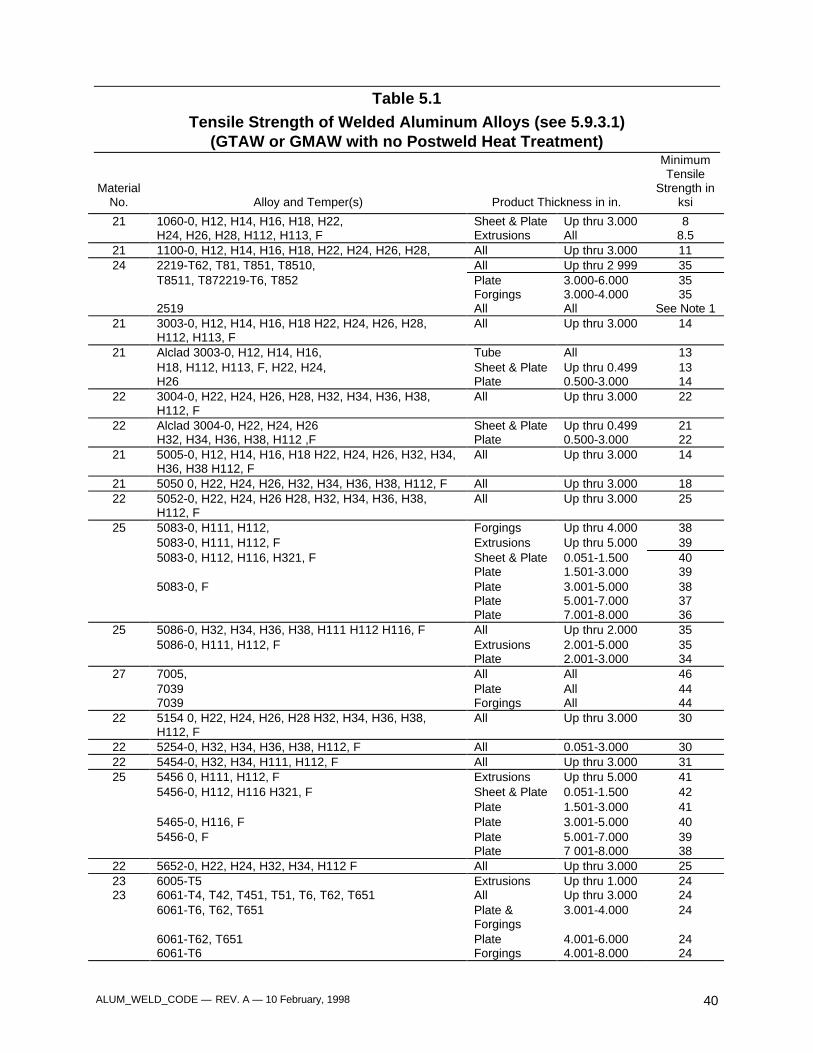
ALUM_WELD_CODE — REV. A — 10 February, 1998 40
Table 5.1Tensile Strength of Welded Aluminum Alloys (see 5.9.3.1)
(GTAW or GMAW with no Postweld Heat Treatment)
MaterialNo. Alloy and Temper(s) Product Thickness in in.
MinimumTensile
Strength inksi
21 1060-0, H12, H14, H16, H18, H22, Sheet & Plate Up thru 3.000 8H24, H26, H28, H112, H113, F Extrusions All 8.5
21 1100-0, H12, H14, H16, H18, H22, H24, H26, H28, All Up thru 3.000 1124 2219-T62, T81, T851, T8510, All Up thru 2 999 35
T8511, T872219-T6, T852 Plate 3.000-6.000 35Forgings 3.000-4.000 35
2519 All All See Note 121 3003-0, H12, H14, H16, H18 H22, H24, H26, H28,
H112, H113, FAll Up thru 3.000 14
21 Alclad 3003-0, H12, H14, H16, Tube All 13H18, H112, H113, F, H22, H24, Sheet & Plate Up thru 0.499 13H26 Plate 0.500-3.000 14
22 3004-0, H22, H24, H26, H28, H32, H34, H36, H38,H112, F
All Up thru 3.000 22
22 Alclad 3004-0, H22, H24, H26 Sheet & Plate Up thru 0.499 21H32, H34, H36, H38, H112 ,F Plate 0.500-3.000 22
21 5005-0, H12, H14, H16, H18 H22, H24, H26, H32, H34,H36, H38 H112, F
All Up thru 3.000 14
21 5050 0, H22, H24, H26, H32, H34, H36, H38, H112, F All Up thru 3.000 1822 5052-0, H22, H24, H26 H28, H32, H34, H36, H38,
H112, FAll Up thru 3.000 25
25 5083-0, H111, H112, Forgings Up thru 4.000 385083-0, H111, H112, F Extrusions Up thru 5.000 395083-0, H112, H116, H321, F Sheet & Plate 0.051-1.500 40
Plate 1.501-3.000 395083-0, F Plate 3.001-5.000 38
Plate 5.001-7.000 37Plate 7.001-8.000 36
25 5086-0, H32, H34, H36, H38, H111 H112 H116, F All Up thru 2.000 355086-0, H111, H112, F Extrusions 2.001-5.000 35
Plate 2.001-3.000 3427 7005, All All 46
7039 Plate All 447039 Forgings All 44
22 5154 0, H22, H24, H26, H28 H32, H34, H36, H38,H112, F
All Up thru 3.000 30
22 5254-0, H32, H34, H36, H38, H112, F All 0.051-3.000 3022 5454-0, H32, H34, H111, H112, F All Up thru 3.000 3125 5456 0, H111, H112, F Extrusions Up thru 5.000 41
5456-0, H112, H116 H321, F Sheet & Plate 0.051-1.500 42Plate 1.501-3.000 41
5465-0, H116, F Plate 3.001-5.000 405456-0, F Plate 5.001-7.000 39
Plate 7 001-8.000 3822 5652-0, H22, H24, H32, H34, H112 F All Up thru 3.000 2523 6005-T5 Extrusions Up thru 1.000 2423 6061-T4, T42, T451, T51, T6, T62, T651 All Up thru 3.000 24
6061-T6, T62, T651 Plate &Forgings
3.001-4.000 24
6061-T62, T651 Plate 4.001-6.000 246061-T6 Forgings 4.001-8.000 24
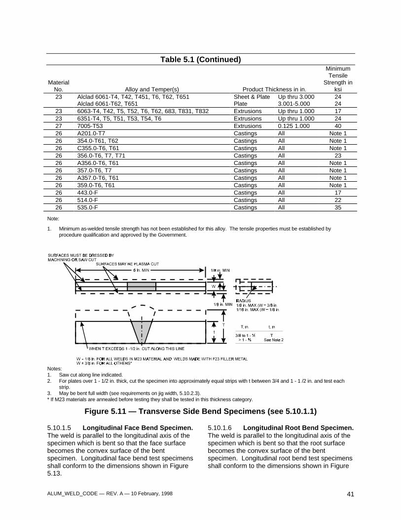
ALUM_WELD_CODE — REV. A — 10 February, 1998 41
Table 5.1 (Continued)
MaterialNo. Alloy and Temper(s) Product Thickness in in.
MinimumTensile
Strength inksi
23 Alclad 6061-T4, T42, T451, T6, T62, T651 Sheet & Plate Up thru 3.000 24Alclad 6061-T62, T651 Plate 3.001-5.000 24
23 6063-T4, T42, T5, T52, T6, T62, 683, T831, T832 Extrusions Up thru 1.000 1723 6351-T4, T5, T51, T53, T54, T6 Extrusions Up thru 1.000 2427 7005-T53 Extrusions 0.125 1.000 4026 A201.0-T7 Castings All Note 126 354.0-T61, T62 Castings All Note 126 C355.0-T6, T61 Castings All Note 126 356.0-T6, T7, T71 Castings All 2326 A356.0-T6, T61 Castings All Note 126 357.0-T6, T7 Castings All Note 126 A357.0-T6, T61 Castings All Note 126 359.0-T6, T61 Castings All Note 126 443.0-F Castings All 1726 514.0-F Castings All 2226 535.0-F Castings All 35
Note:
1. Minimum as-welded tensile strength has not been established for this alloy. The tensile properties must be established byprocedure qualification and approved by the Government.
Notes:1. Saw cut along line indicated.2. For plates over 1 - 1/2 in. thick, cut the specimen into approximately equal strips with t between 3/4 and 1 - 1 /2 in. and test each
strip.3. May be bent full width (see requirements on jig width, 5.10.2.3).* If M23 materials are annealed before testing they shall be tested in this thickness category.
Figure 5.11 — Transverse Side Bend Specimens (see 5.10.1.1)
5.10.1.5 Longitudinal Face Bend Specimen.The weld is parallel to the longitudinal axis of thespecimen which is bent so that the face surfacebecomes the convex surface of the bentspecimen. Longitudinal face bend test specimensshall conform to the dimensions shown in Figure5.13.
5.10.1.6 Longitudinal Root Bend Specimen.The weld is parallel to the longitudinal axis of thespecimen which is bent so that the root surfacebecomes the convex surface of the bentspecimen. Longitudinal root bend test specimensshall conform to the dimensions shown in Figure
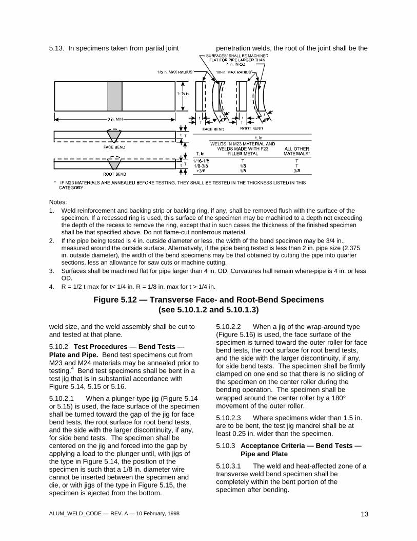
ALUM_WELD_CODE — REV. A — 10 February, 1998 13
5.13. In specimens taken from partial joint penetration welds, the root of the joint shall be the
Notes:1. Weld reinforcement and backing strip or backing ring, if any, shall be removed flush with the surface of the
specimen. If a recessed ring is used, this surface of the specimen may be machined to a depth not exceedingthe depth of the recess to remove the ring, except that in such cases the thickness of the finished specimenshall be that specified above. Do not flame-cut nonferrous material.
2. If the pipe being tested is 4 in. outside diameter or less, the width of the bend specimen may be 3/4 in.,measured around the outside surface. Alternatively, if the pipe being tested is less than 2 in. pipe size (2.375in. outside diameter), the width of the bend specimens may be that obtained by cutting the pipe into quartersections, less an allowance for saw cuts or machine cutting.
3. Surfaces shall be machined flat for pipe larger than 4 in. OD. Curvatures hall remain where-pipe is 4 in. or lessOD.
4. R = 1/2 t max for t< 1/4 in. R = 1/8 in. max for t > 1/4 in.
Figure 5.12 — Transverse Face- and Root-Bend Specimens(see 5.10.1.2 and 5.10.1.3)
weld size, and the weld assembly shall be cut toand tested at that plane.
5.10.2 Test Procedures — Bend Tests —Plate and Pipe. Bend test specimens cut fromM23 and M24 materials may be annealed prior totesting.4 Bend test specimens shall be bent in atest jig that is in substantial accordance withFigure 5.14, 5.15 or 5.16.
5.10.2.1 When a plunger-type jig (Figure 5.14or 5.15) is used, the face surface of the specimenshall be turned toward the gap of the jig for facebend tests, the root surface for root bend tests,and the side with the larger discontinuity, if any,for side bend tests. The specimen shall becentered on the jig and forced into the gap byapplying a load to the plunger until, with jigs ofthe type in Figure 5.14, the position of thespecimen is such that a 1/8 in. diameter wirecannot be inserted between the specimen anddie, or with jigs of the type in Figure 5.15, thespecimen is ejected from the bottom.
5.10.2.2 When a jig of the wrap-around type(Figure 5.16) is used, the face surface of thespecimen is turned toward the outer roller for facebend tests, the root surface for root bend tests,and the side with the larger discontinuity, if any,for side bend tests. The specimen shall be firmlyclamped on one end so that there is no sliding ofthe specimen on the center roller during thebending operation. The specimen shall bewrapped around the center roller by a 180°movement of the outer roller.
5.10.2.3 Where specimens wider than 1.5 in.are to be bent, the test jig mandrel shall be atleast 0.25 in. wider than the specimen.
5.10.3 Acceptance Criteria — Bend Tests —Pipe and Plate
5.10.3.1 The weld and heat-affected zone of atransverse weld bend specimen shall becompletely within the bent portion of thespecimen after bending.
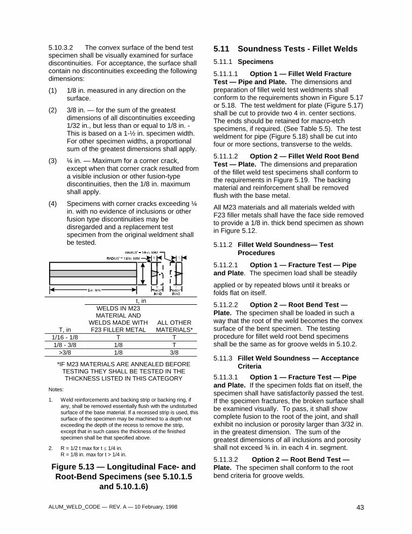
ALUM_WELD_CODE — REV. A — 10 February, 1998 43
5.10.3.2 The convex surface of the bend testspecimen shall be visually examined for surfacediscontinuities. For acceptance, the surface shallcontain no discontinuities exceeding the followingdimensions:
(1) 1/8 in. measured in any direction on thesurface.
(2) 3/8 in. — for the sum of the greatestdimensions of all discontinuities exceeding1/32 in., but less than or equal to 1/8 in. -This is based on a 1-½ in. specimen width.For other specimen widths, a proportionalsum of the greatest dimensions shall apply.
(3) ¼ in. — Maximum for a corner crack,except when that corner crack resulted froma visible inclusion or other fusion-typediscontinuities, then the 1/8 in. maximumshall apply.
(4) Specimens with corner cracks exceeding ¼in. with no evidence of inclusions or otherfusion type discontinuities may bedisregarded and a replacement testspecimen from the original weldment shallbe tested.
t, in
T, in
WELDS IN M23MATERIAL AND
WELDS MADE WITHF23 FILLER METAL
ALL OTHERMATERIALS*
1/16 - 1/8 T T1/8 - 3/8 1/8 T
>3/8 1/8 3/8
*IF M23 MATERIALS ARE ANNEALED BEFORETESTING THEY SHALL BE TESTED IN THETHICKNESS LISTED IN THIS CATEGORY
Notes:
1. Weld reinforcements and backing strip or backing ring, ifany, shall be removed essentially flush with the undisturbedsurface of the base material. If a recessed strip is used, thissurface of the specimen may be machined to a depth notexceeding the depth of the recess to remove the strip,except that in such cases the thickness of the finishedspecimen shall be that specified above.
2. R = 1/2 t max for t ≤ 1/4 in.R = 1/8 in. max for t > 1/4 in.
Figure 5.13 — Longitudinal Face- andRoot-Bend Specimens (see 5.10.1.5
and 5.10.1.6)
5.11 Soundness Tests - Fillet Welds
5.11.1 Specimens
5.11.1.1 Option 1 — Fillet Weld FractureTest — Pipe and Plate. The dimensions andpreparation of fillet weld test weldments shallconform to the requirements shown in Figure 5.17or 5.18. The test weldment for plate (Figure 5.17)shall be cut to provide two 4 in. center sections.The ends should be retained for macro-etchspecimens, if required. (See Table 5.5). The testweldment for pipe (Figure 5.18) shall be cut intofour or more sections, transverse to the welds.
5.11.1.2 Option 2 — Fillet Weld Root BendTest — Plate. The dimensions and preparationof the fillet weld test specimens shall conform tothe requirements in Figure 5.19. The backingmaterial and reinforcement shall be removedflush with the base metal.
All M23 materials and all materials welded withF23 filler metals shall have the face side removedto provide a 1/8 in. thick bend specimen as shownin Figure 5.12.
5.11.2 Fillet Weld Soundness— TestProcedures
5.11.2.1 Option 1 — Fracture Test — Pipeand Plate. The specimen load shall be steadily
applied or by repeated blows until it breaks orfolds flat on itself.
5.11.2.2 Option 2 — Root Bend Test —Plate. The specimen shall be loaded in such away that the root of the weld becomes the convexsurface of the bent specimen. The testingprocedure for fillet weld root bend specimensshall be the same as for groove welds in 5.10.2.
5.11.3 Fillet Weld Soundness — AcceptanceCriteria
5.11.3.1 Option 1 — Fracture Test — Pipeand Plate. If the specimen folds flat on itself, thespecimen shall have satisfactorily passed the test.If the specimen fractures, the broken surface shallbe examined visually. To pass, it shall showcomplete fusion to the root of the joint, and shallexhibit no inclusion or porosity larger than 3/32 in.in the greatest dimension. The sum of thegreatest dimensions of all inclusions and porosityshall not exceed ¾ in. in each 4 in. segment.
5.11.3.2 Option 2 — Root Bend Test —Plate. The specimen shall conform to the rootbend criteria for groove welds.
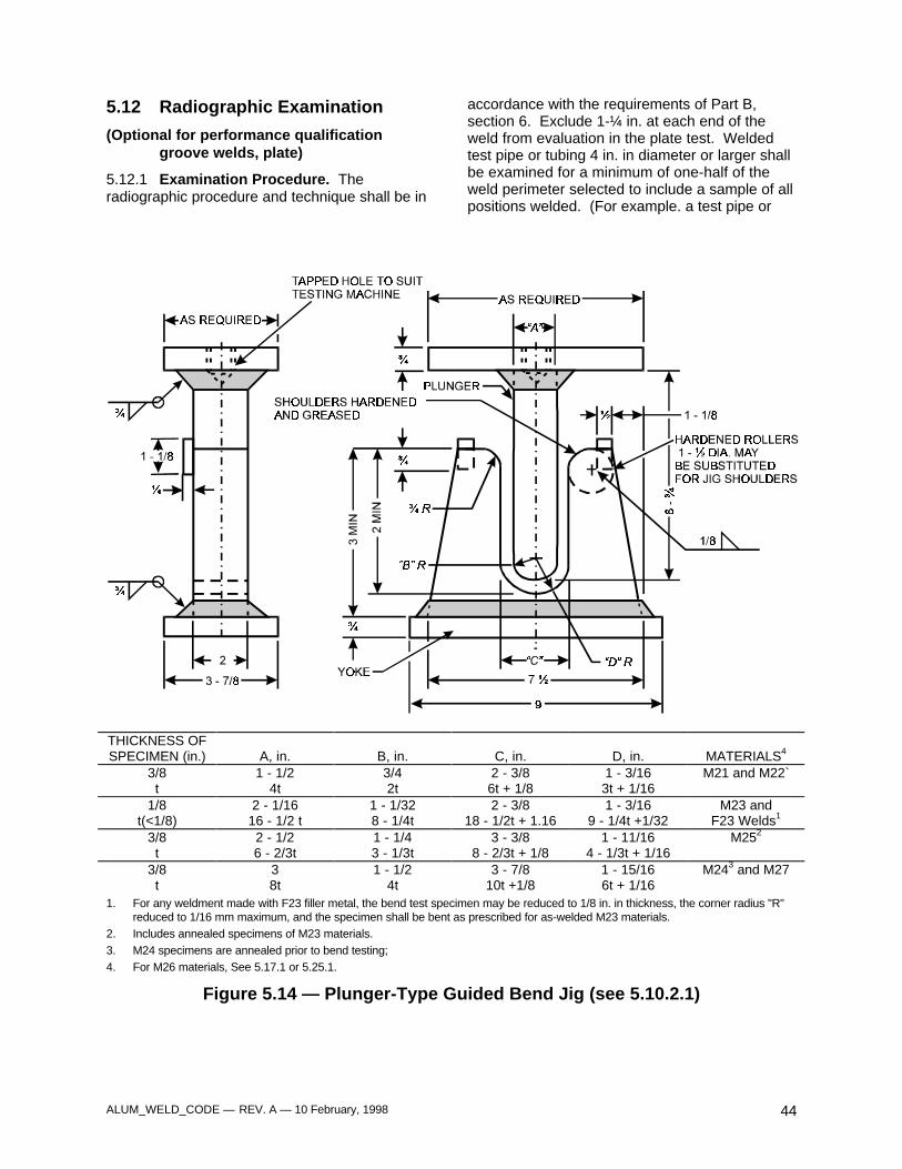
ALUM_WELD_CODE — REV. A — 10 February, 1998 44
5.12 Radiographic Examination
(Optional for performance qualificationgroove welds, plate)
5.12.1 Examination Procedure. Theradiographic procedure and technique shall be in
accordance with the requirements of Part B,section 6. Exclude 1-¼ in. at each end of theweld from evaluation in the plate test. Weldedtest pipe or tubing 4 in. in diameter or larger shallbe examined for a minimum of one-half of theweld perimeter selected to include a sample of allpositions welded. (For example. a test pipe or
THICKNESS OFSPECIMEN (in.) A, in. B, in. C, in. D, in. MATERIALS4
3/8 1 - 1/2 3/4 2 - 3/8 1 - 3/16 M21 and M22`t 4t 2t 6t + 1/8 3t + 1/16
1/8 2 - 1/16 1 - 1/32 2 - 3/8 1 - 3/16 M23 andt(<1/8) 16 - 1/2 t 8 - 1/4t 18 - 1/2t + 1.16 9 - 1/4t +1/32 F23 Welds1
3/8 2 - 1/2 1 - 1/4 3 - 3/8 1 - 11/16 M252
t 6 - 2/3t 3 - 1/3t 8 - 2/3t + 1/8 4 - 1/3t + 1/163/8 3 1 - 1/2 3 - 7/8 1 - 15/16 M243 and M27t 8t 4t 10t +1/8 6t + 1/16
1. For any weldment made with F23 filler metal, the bend test specimen may be reduced to 1/8 in. in thickness, the corner radius "R"reduced to 1/16 mm maximum, and the specimen shall be bent as prescribed for as-welded M23 materials.
2. Includes annealed specimens of M23 materials.3. M24 specimens are annealed prior to bend testing;4. For M26 materials, See 5.17.1 or 5.25.1.
Figure 5.14 — Plunger-Type Guided Bend Jig (see 5.10.2.1)
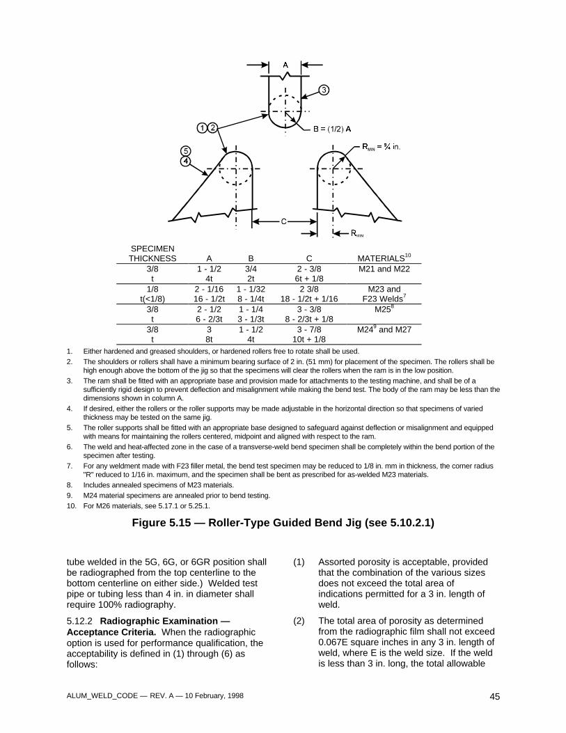
ALUM_WELD_CODE — REV. A — 10 February, 1998 45
SPECIMENTHICKNESS A B C MATERIALS10
3/8 1 - 1/2 3/4 2 - 3/8 M21 and M22t 4t 2t 6t + 1/8
1/8 2 - 1/16 1 - 1/32 2 3/8 M23 andt(<1/8) 16 - 1/2t 8 - 1/4t 18 - 1/2t + 1/16 F23 Welds7
3/8 2 - 1/2 1 - 1/4 3 - 3/8 M258
t 6 - 2/3t 3 - 1/3t 8 - 2/3t + 1/83/8 3 1 - 1/2 3 - 7/8 M249 and M27t 8t 4t 10t + 1/8
1. Either hardened and greased shoulders, or hardened rollers free to rotate shall be used.2. The shoulders or rollers shall have a minimum bearing surface of 2 in. (51 mm) for placement of the specimen. The rollers shall be
high enough above the bottom of the jig so that the specimens will clear the rollers when the ram is in the low position.3. The ram shall be fitted with an appropriate base and provision made for attachments to the testing machine, and shall be of a
sufficiently rigid design to prevent deflection and misalignment while making the bend test. The body of the ram may be less than thedimensions shown in column A.
4. If desired, either the rollers or the roller supports may be made adjustable in the horizontal direction so that specimens of variedthickness may be tested on the same jig.
5. The roller supports shall be fitted with an appropriate base designed to safeguard against deflection or misalignment and equippedwith means for maintaining the rollers centered, midpoint and aligned with respect to the ram.
6. The weld and heat-affected zone in the case of a transverse-weld bend specimen shall be completely within the bend portion of thespecimen after testing.
7. For any weldment made with F23 filler metal, the bend test specimen may be reduced to 1/8 in. mm in thickness, the corner radius"R" reduced to 1/16 in. maximum, and the specimen shall be bent as prescribed for as-welded M23 materials.
8. Includes annealed specimens of M23 materials.9. M24 material specimens are annealed prior to bend testing.10. For M26 materials, see 5.17.1 or 5.25.1.
Figure 5.15 — Roller-Type Guided Bend Jig (see 5.10.2.1)
tube welded in the 5G, 6G, or 6GR position shallbe radiographed from the top centerline to thebottom centerline on either side.) Welded testpipe or tubing less than 4 in. in diameter shallrequire 100% radiography.
5.12.2 Radiographic Examination —Acceptance Criteria. When the radiographicoption is used for performance qualification, theacceptability is defined in (1) through (6) asfollows:
(1) Assorted porosity is acceptable, providedthat the combination of the various sizesdoes not exceed the total area ofindications permitted for a 3 in. length ofweld.
(2) The total area of porosity as determinedfrom the radiographic film shall not exceed0.067E square inches in any 3 in. length ofweld, where E is the weld size. If the weldis less than 3 in. long, the total allowable
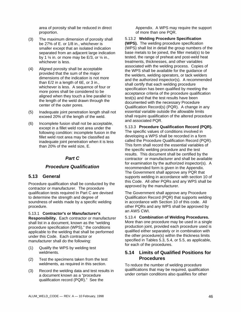
ALUM_WELD_CODE — REV. A — 10 February, 1998 46
area of porosity shall be reduced in directproportion.
(3) The maximum dimension of porosity shallbe 27% of E. or 1/8 in., whichever issmaller except that an isolated indicationseparated from an adjacent large indicationby 1 ¼ in. or more may be E/3, or ¼ in.,whichever is less.
(4) Aligned porosity shall be acceptableprovided that the sum of the majordimensions of the indication is not morethan E/2 in a length of 6E, or 3 in.,whichever is less. A sequence of four ormore pores shall be considered to bealigned when they touch a line parallel tothe length of the weld drawn through thecenter of the outer pores.
(5) Inadequate joint penetration length shall notexceed 20% of the length of the weld.
(6) Incomplete fusion shall not be acceptable,except in a fillet weld root area under thefollowing condition: incomplete fusion in thefillet weld root area may be classified asinadequate joint penetration when it is lessthan 20% of the weld size, E.
Part C
Procedure Qualification
5.13 General
Procedure qualification shall be conducted by thecontractor or manufacturer. The procedurequalification tests required In Part C are devisedto determine the strength and degree ofsoundness of welds made by a specific weldingprocedure.
5.13.1 Contractor's or Manufacturer'sResponsibility. Each contractor or manufacturershall list in a document, known as the “weldingprocedure specification (WPS),” the conditionsapplicable to the welding that shall be performedunder this Code. Each contractor ormanufacturer shall do the following:
(1) Qualify the WPS by welding testweldments.
(2) Test the specimens taken from the testweldments, as required in this section.
(3) Record the welding data and test results ina document known as a “procedurequalification record (PQR).” See the
Appendix. A WPS may require the supportof more than one PQR.
5.13.2 Welding Procedure Specification(WPS). The welding procedure specification(WPS) shall list in detail the group numbers of thebase metals to be joined, the filler metal(s) to betested, the range of preheat and post-weld heattreatments, thicknesses, and other variablesassociated with the welding process. Copies ofthe WPS shall be available for the guidance ofthe welders, welding operators, or tack weldersand the authorized inspector(s). A recommendedshall certify that each welding procedurespecification has been qualified by meeting theacceptance criteria of the procedure qualificationtest(s) and that the test results have beendocumented with the necessary ProcedureQualification Record(s) (PQR). A change in anyessential variable outside the allowable limitsshall require qualification of the altered procedureand associated PQR.
5.13.3 Procedure Qualification Record (PQR).The specific values of conditions involved indeveloping a WPS shall be recorded in a formcalled the Procedure Qualification Record (PQR).This form shall record the essential variables ofthe specific welding procedure and the testresults. This document shall be certified by thecontractor or manufacturer and shall be availablefor examination by the authorized inspector(s). Arecommended form is given in the Appendix.The Government shall approve any PQR thatsupports welding in accordance with section 10 ofthis Code. All other PQRs and any WPS shall beapproved by the manufacturer.
The Government shall approve any ProcedureQualification Record (PQR) that supports weldingin accordance with Section 10 of this code. Allother PQRs and any WPS shall be approved byan AWS CWI.
5.13.4 Combination of Welding Procedures.More than one procedure may be used in a singleproduction joint, provided each procedure used isqualified either separately or in combination withthe other procedure(s) within the thickness limitsspecified in Tables 5.3, 5.4, or 5.5, as applicable,for each of the procedures.
5.14 Limits of Qualified Positions forProcedures
To reduce the number of welding procedurequalifications that may be required, qualificationunder certain conditions also qualifies for other
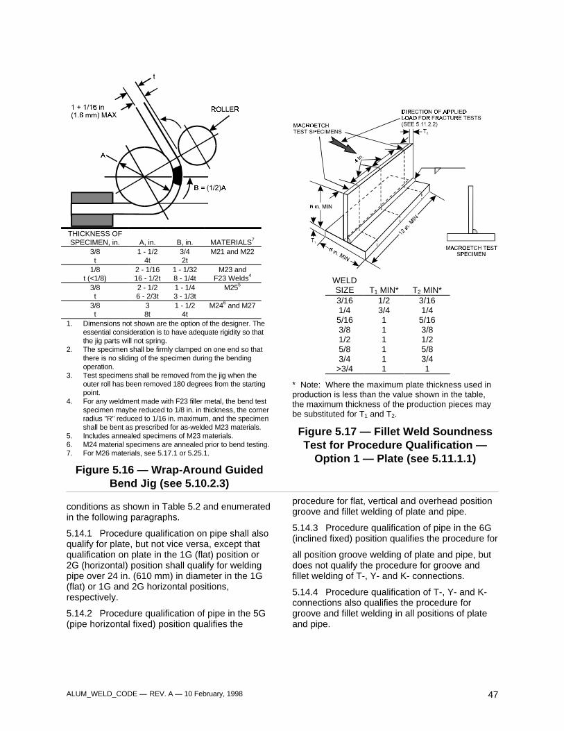
ALUM_WELD_CODE — REV. A — 10 February, 1998 47
THICKNESS OFSPECIMEN, in. A, in. B, in. MATERIALS7
3/8 1 - 1/2 3/4 M21 and M22t 4t 2t
1/8 2 - 1/16 1 - 1/32 M23 andt (<1/8) 16 - 1/2t 8 - 1/4t F23 Welds4
3/8 2 - 1/2 1 - 1/4 M255
t 6 - 2/3t 3 - 1/3t3/8 3 1 - 1/2 M246 and M27t 8t 4t
1. Dimensions not shown are the option of the designer. Theessential consideration is to have adequate rigidity so thatthe jig parts will not spring.
2. The specimen shall be firmly clamped on one end so thatthere is no sliding of the specimen during the bendingoperation.
3. Test specimens shall be removed from the jig when theouter roll has been removed 180 degrees from the startingpoint.
4. For any weldment made with F23 filler metal, the bend testspecimen maybe reduced to 1/8 in. in thickness, the cornerradius "R" reduced to 1/16 in. maximum, and the specimenshall be bent as prescribed for as-welded M23 materials.
5. Includes annealed specimens of M23 materials.6. M24 material specimens are annealed prior to bend testing.7. For M26 materials, see 5.17.1 or 5.25.1.
Figure 5.16 — Wrap-Around GuidedBend Jig (see 5.10.2.3)
WELDSIZE T1 MIN* T2 MIN*3/16 1/2 3/161/4 3/4 1/45/16 1 5/163/8 1 3/81/2 1 1/25/8 1 5/83/4 1 3/4
>3/4 1 1
* Note: Where the maximum plate thickness used inproduction is less than the value shown in the table,the maximum thickness of the production pieces maybe substituted for T1 and T2.
Figure 5.17 — Fillet Weld SoundnessTest for Procedure Qualification —
Option 1 — Plate (see 5.11.1.1)
conditions as shown in Table 5.2 and enumeratedin the following paragraphs.
5.14.1 Procedure qualification on pipe shall alsoqualify for plate, but not vice versa, except thatqualification on plate in the 1G (flat) position or2G (horizontal) position shall qualify for weldingpipe over 24 in. (610 mm) in diameter in the 1G(flat) or 1G and 2G horizontal positions,respectively.
5.14.2 Procedure qualification of pipe in the 5G(pipe horizontal fixed) position qualifies the
procedure for flat, vertical and overhead positiongroove and fillet welding of plate and pipe.
5.14.3 Procedure qualification of pipe in the 6G(inclined fixed) position qualifies the procedure for
all position groove welding of plate and pipe, butdoes not qualify the procedure for groove andfillet welding of T-, Y- and K- connections.
5.14.4 Procedure qualification of T-, Y- and K-connections also qualifies the procedure forgroove and fillet welding in all positions of plateand pipe.
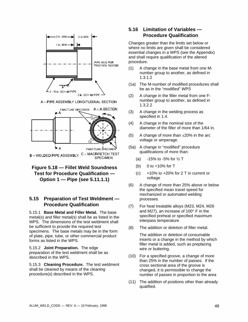
ALUM_WELD_CODE — REV. A — 10 February, 1998 48
Figure 5.18 — Fillet Weld SoundnessTest for Procedure Qualification —
Option 1 — Pipe (see 5.11.1.1)
5.15 Preparation of Test Weldment —Procedure Qualification
5.15.1 Base Metal and Filler Metal. The basemetal(s) and filler metal(s) shall be as listed in theWPS. The dimensions of the test weldment shallbe sufficient to provide the required testspecimens. The base metals may be in the formof plate, pipe, tube, or other commercial productforms as listed in the WPS.
5.15.2 Joint Preparation. The edgepreparation of the test weldment shall be asdescribed in the WPS.
5.15.3 Cleaning Procedure. The test weldmentshall be cleaned by means of the cleaningprocedure(s) described in the WPS.
5.16 Limitation of Variables —Procedure Qualification
Changes greater than the limits set below orwhere no limits are given shall be consideredessential changes in a WPS (see the Appendix)and shall require qualification of the alteredprocedure.
(1) A change in the base metal from one M-number group to another, as defined in1.3.1.2
(1a) The M-number of modified procedures shallbe as in the “modified” WPS
(2) A change in the filler metal from one F-number group to another, as defined in1.3.2.2
(3) A change in the welding process asspecified in 1.4.
(4) A change in the nominal size of thediameter of the filler of more than 1/64 in.
(5) A change of more than ±20% in the arcvoltage or amperage.
(5a) A change in “modified” procedurequalifications of more than:
(a) -15% to -5% for ½ T
(b) 0 to +10% for T
(c) +10% to +20% for 2 T in current orvoltage
(6) A change of more than 25% above or belowthe specified mean travel speed formechanized or automated weldingprocesses.
(7) For heat treatable alloys (M23, M24, M26and M27), an increase of 100° F in thespecified preheat or specified maximuminterpass temperature
(8) The addition or deletion of filler metal.
The addition or deletion of consumableinserts or a change in the method by whichfiller metal is added, such as preplacingwire or buttering.
(10) For a specified groove, a change of morethan 25% in the number of passes. If thecross sectional area of the groove ischanged, it is permissible to change thenumber of passes in proportion to the area
(11) The addition of positions other than alreadyqualified.
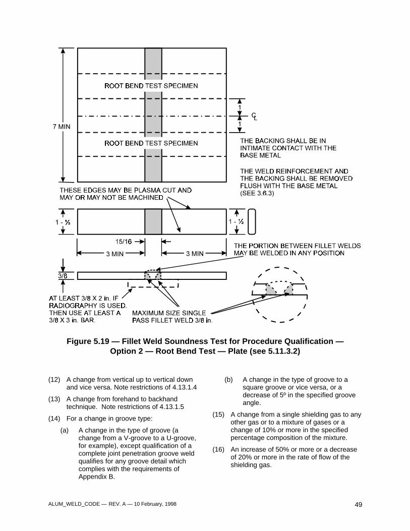
ALUM_WELD_CODE — REV. A — 10 February, 1998 49
Figure 5.19 — Fillet Weld Soundness Test for Procedure Qualification —Option 2 — Root Bend Test — Plate (see 5.11.3.2)
(12) A change from vertical up to vertical downand vice versa. Note restrictions of 4.13.1.4
(13) A change from forehand to backhandtechnique. Note restrictions of 4.13.1.5
(14) For a change in groove type:
(a) A change in the type of groove (achange from a V-groove to a U-groove,for example), except qualification of acomplete joint penetration groove weldqualifies for any groove detail whichcomplies with the requirements ofAppendix B.
(b) A change in the type of groove to asquare groove or vice versa, or adecrease of 5º in the specified grooveangle.
(15) A change from a single shielding gas to anyother gas or to a mixture of gases or achange of 10% or more in the specifiedpercentage composition of the mixture.
(16) An increase of 50% or more or a decreaseof 20% or more in the rate of flow of theshielding gas.
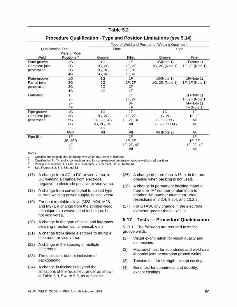
ALUM_WELD_CODE — REV. A — 10 February, 1998 50
Table 5.2
Procedure Qualification - Type and Position Limitations (see 5.14)Type of Weld and Position of Welding Qualified *
Qualification Test Plate Pipe
WeldPlate or PipePositions** Groove Fillet Groove Fillet
Plate-groove 1G 1G 1F 1G(Note 1) 1F(Note 1)Complete joint 2G 1G, 2G 1F, 2F 1G, 2G (Note 1) 1F, 2F (Note 1)penetration 3G 1G, 3G 1F, 3F
4G 1G, 4G 1F, 4FPlate-groove 1G 1G 1F 1G(Note 1) 1F(Note 1)Partial joint 2G 2G 1F, 2F 1G, 2G (Note 1) 1F, 2F (Note 1)penetration 3G 3G 3F
4G 4G 4FPlate-fillet 1F 1F 1F(Note 1)
2F 1F, 2F 1F, 2F (Note 1)3F 3F 5F(Note 1)4F 4F 4F (Note 1)
Pipe-groove 1G 1G 1F 1G 1FComplete joint 2G 1G, 2G 1F, 2F 1G, 2G 1F, 2Fpenetration 5G 1G, 3G, 4G 1F, 2F, 3F 1G, 2G, 5G All
6G 1G, 2G, 3G,4G
All 1G, 2G, 5G 6G All
6GR All All All (Note 2) AllPipe-fillet 1F 1F 1F
2F, 2FR 1F, 2F 1F, 2F4F 1F, 2F, 4F 1F, 2F, 4F5F All All
Notes:1 Qualifies for welding pipe or tubing over 24 in. (610 mm) in diameter.2. Qualifies for T-, Y-, and K-connections and for complete joint penetration groove welds in all positions* Positions of welding: F = Flat, H = Horizontal, V = Vertical, OH = Overhead.** See Figures 5.3, 5.4, 5.5 and 5.6.
(17) A change from AC to DC or vice versa; inDC welding a change from electrodenegative to electrode positive or vice versa.
(18) A change from conventional to pulsed typecurrent welding power supply, or vice versa
(19) For heat treatable alloys (M23, M24, M26,and M27), a change from the stringer-beadtechnique to a weave bead technique, butnot vice versa.
(20) A change in the type of initial and interpasscleaning (mechanical, chemical, etc.)
(21) A change from single electrode to multipleelectrode, or vice versa.
(22) A change in the spacing of multipleelectrodes.
(23) The omission, but not inclusion ofbackgouging.
(24) A change in thickness beyond thelimitations of the “qualified range” as shownin Table 5.3, 5.4, or 5.5, as applicable.
(25) A change of more than 1/16 in. in the rootopening when backing is not used.
(26) A change in permanent backing materialfrom one “M” number of aluminum toanother “M” number aluminum. Noterestrictions in 8.2.4, 9.2.4, and 10.2.3.
(27) For GTAW, any change in the electrodediameter greater than ±1/32 in.
5.17 Tests — Procedure Qualification
5.17.1 The following are required tests forgroove welds:
(1) Visual examination for visual quality anddimensions.
(2) Macroetch test for soundness and weld sizein partial joint penetration groove welds.
(3) Tension test for strength, except castings.
(4) Bend test for soundness and ductility,except castings.

ALUM_WELD_CODE — REV. A — 10 February, 1998 51
(5) When welding castings to other castings orwrought material, the bend test forsoundness and ductility of groove weldsand fillet welds shall be omitted, and amacroetch test for weld soundness shall beconducted.
5.17.2 The following are required tests for filletwelds:
(1) Visual examination for appearance anddimensions.
(2) Macroetch test for penetration.
(3) Fracture test for soundness or root bendtest for soundness, except castings
5.17.3 Test Specimens: Number, Type andPreparation
5.17.3.1 The type and number of specimensthat shall be tested to qualify a welding procedurefor complete joint penetration groove welds onplate, pipe, or tubing are shown in Table 5.3,together with the range of thicknesses qualifiedfor use in construction. The range is based on thethickness of the plate, pipe or tubing used inmaking the qualification.
5.17.3.2 The type and number of specimensthat shall be tested to qualify a welding procedurefor partial joint penetration groove welds areshown in Table 5.4. A sample weld shall bemade using the type of groove design and jointwelding procedure to be used in construction,except the depth of groove need not exceed 1 in.If the partial joint penetration groove weld is to beused for corner or T-joints, the butt joint shallhave a temporary restrictive plate in the plane ofthe square face to simulate the T-jointconfiguration.
5.17.3.3 When a joint welding procedure hasbeen qualified for a complete joint penetrationgroove weld and is applied as the weldingprocedure for a partial joint penetration grooveweld falling within the limitation of variables, threemacroetch specimens are required.
5.17.3.4 The type and number of specimensthat shall be tested to qualify a welding procedurefor fillet welds are shown in Table 5.5.
5.17.4 Location of Removal of TestSpecimens for Procedure Qualification. Onesample weldment of sufficient size to obtain thenumber of test specimens required by Table 5.3,5.4 or 5.5, as applicable, shall be prepared inaccordance with the welding procedurespecification.
5.17.4.1 Test Specimens — Groove Welds— Plate. The order of removal of test specimensshall conform to Figure 5.20(A), 5.20(B) or5.20(C). Complete joint penetration groove weldsmade on plates ¾ in. or greater in thicknesswhich are welded using two-side weldingtechniques shall be tested using the testspecimens in Figure 5.20(B). Partial jointpenetration groove welds made on plates 3/8 in,or greater in thickness shall be tested with theunfused side machined off to the depth of theeffective weld size. For base metals andcombinations of base and filler metals whichdiffer significantly in ductility, test specimencoupons as shown in Figure 5-20(C) shall beused.
5.17.4.2 Partial Joint Penetration GrooveWelds — Plate or Pipe. The type and number ofspecimens that shall be tested to qualify awelding procedure are shown in Table 5.4. Asample weld shall be made using the type ofgroove design and joint welding procedure to beused in construction, except the depth of grooveneed not exceed 1 in.
If the partial joint penetration groove weld is to beused for corner or T-joints, the butt joints shallhave a temporary restrictive plate in the plane ofthe square face to simulate the T-jointconfiguration. The sample weld shall be tested asfollows:
(1) When a joint welding procedure has beenqualified for a complete joint penetrationgroove weld and is applied to the weldingconditions of a partial joint penetrationgroove weld, three macroetch cross sectiontest specimens are required; there shall beone specimen from each end of the sampleweldment, and one from the center.
(2) If a joint welding procedure is not coveredby (1), then a sample weldment shall beprepared and a macroetch test specimenmade to determine the weld size. Then theexcess material is machined off the bottomside of the joint to the thickness of the weldsize.
Tension and bend specimens shall be preparedand tests performed, as required for completejoint penetration groove welds.
5.17.4.3 Test Specimens — Groove Welds.— Pipe. The order of removal of test specimensshall conform to Figure 5.21, 5.22 or 5.24.
5.17.4.4 Test Specimens — Fillet Welds.The number and type of test specimens that shallbe tested to qualify a welding procedure are
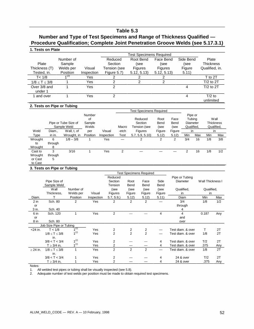
ALUM_WELD_CODE — REV. A — 10 February, 1998 52
Table 5.3Number and Type of Test Specimens and Range of Thickness Qualified —
Procedure Qualification; Complete Joint Penetration Groove Welds (see 5.17.3.1)1. Tests on Plate
Test Specimens Required
PlateThickness (T)
Tested, in.
Number ofSample
Welds perPosition
VisualInspection
ReducedSection
Tension (seeFigure 5.7)
Root Bend(see
Figures5.12, 5.13)
Face Bend(see
Figures5.12, 5.13)
Side Bend(see
Figure5.11)
PlateThickness
Qualified, in.
T< 1/8 1(2) Yes 2 2 2 T to 2T1/8 ≤ T ≤ 3/8 1 Yes 2 2 2 T/2 to 2TOver 3/8 and
under 11 Yes 2 4 T/2 to 2T
1 and over 1 Yes 2 4 T/2 tounlimited
2. Tests on Pipe or TubingTest Specimens Required
Pipe or Tube Size ofSample Weld
Numberof
SampleWelds Macro
ReducedSection
Tension (see
RootBend(see
FaceBend(see
Pipe orTubing
DiameterQualified,
WallThicknessQualified,
Weld Diam., Wall, t, of per Visual -etch Figures Figure Figure in inType in in. Wrought, in Position Inspection Test 5.7, 5.9, 5.10) 5.12) 5.12) Min Max Min Max
Wroughtto
Wrought
6through
8
1/8 – 3/8 1 Yes — 2 2 2 3/4 16 1/8 3/8
Cast toWroughtor Castto Cast
3through
5
3/16 1 Yes 2 — — — 2 16 1/8 1/2
3. Tests on Pipe or TubingTest Specimens Required
Pipe Size ofSample Weld
ReducedSectionTension
RootBend
FaceBend
SideBend
Pipe or TubingDiameter Wall Thickness l
WallThickness,
Number ofWelds per Visual
(seeFigures
(seeFigure
(seeFigure
(seeFigure
Qualified,in
Qualified,in
Diam. T Position Inspection 5.7, 5.9,) 5.12) 5.12) 5.11) Diam Min Max2 inor
3 in.
Sch. 80
Sch. 40
2 Yes 2 2 2 — 3/4through
4
1/8 1/2
6 inor
8 in
Sch. 120
Sch. 80
1 Yes 2 — — 4 4andover
0.187 Any
Job Size Pipe or Tubing<24 in. T < 1/8 1(2) Yes 2 2 2 — Test diam. & over T 2T
1/8 ≤ T ≤ 3/8in.
1(2) Yes 2 2 2 — Test diam. & over 1/8 2T
3/8 < T < 3/4 1(2) Yes 2 — — 4 Test diam. & over T/2 2TT ≥ 3/4 in, 1(2) Yes 2 — — 4 Test diam. & over .375 Any
≥ 24 in. 1/8 ≤ T ≤ 3/8in.
1 Yes 2 2 2 — Test diam. & over 1/8 2T
3/8 < T < 3/4 1 Yes 2 — — 4 24 & over T/2 2TT ≥ 3/4 in, 1 Yes 2 — — 4 24 & over .375 Any
Notes:1. All welded test pipes or tubing shall be visually inspected (see 5.8).2. Adequate number of test welds per position must be made to obtain required test specimens.
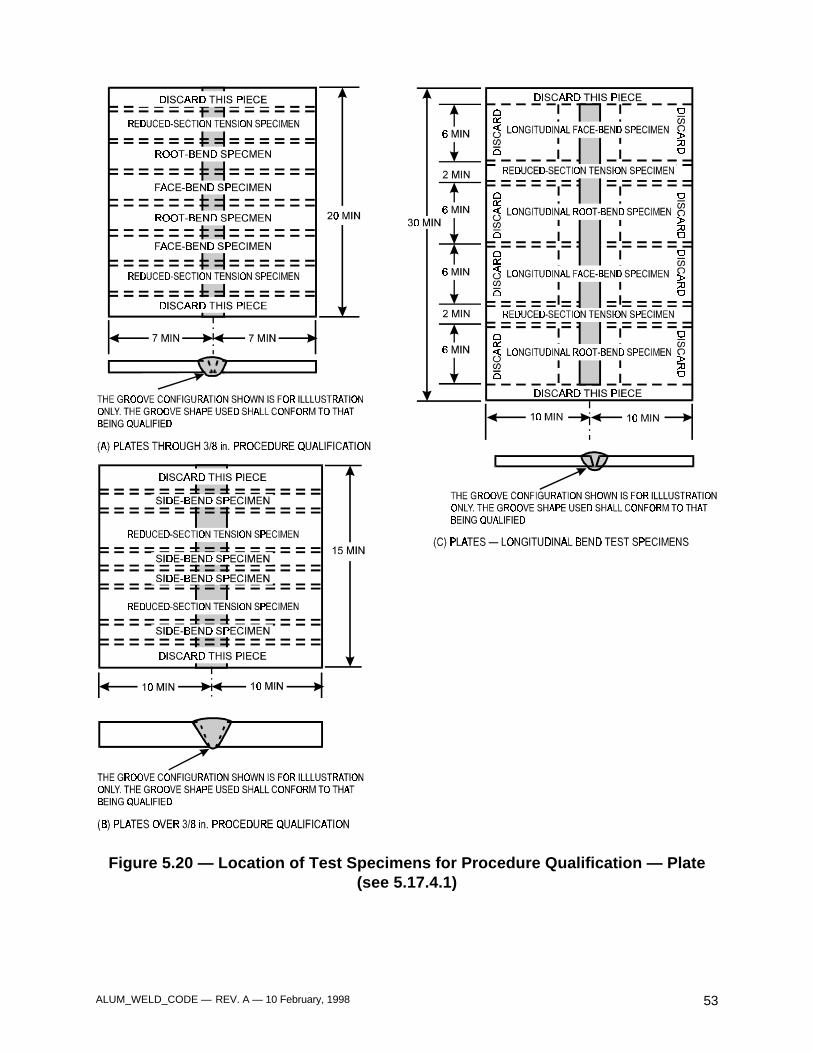
ALUM_WELD_CODE — REV. A — 10 February, 1998 53
Figure 5.20 — Location of Test Specimens for Procedure Qualification — Plate(see 5.17.4.1)
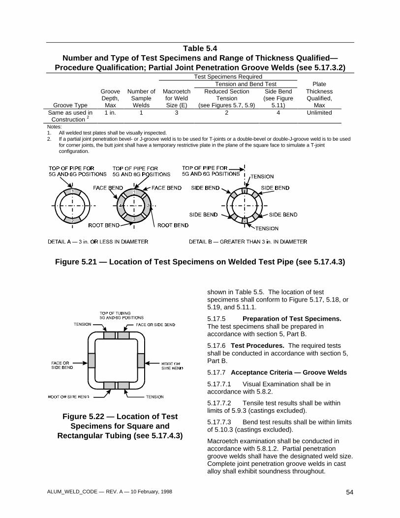
ALUM_WELD_CODE — REV. A — 10 February, 1998 54
Table 5.4Number and Type of Test Specimens and Range of Thickness Qualified—
Procedure Qualification; Partial Joint Penetration Groove Welds (see 5.17.3.2)Test Specimens Required
Tension and Bend Test Plate
Groove Type
GrooveDepth,Max
Number ofSampleWelds
Macroetchfor WeldSize (E)
Reduced SectionTension
(see Figures 5.7, 5.9)
Side Bend(see Figure
5.11)
ThicknessQualified,
MaxSame as used in
Construction 21 in. 1 3 2 4 Unlimited
Notes:1. All welded test plates shall be visually inspected.2. If a partial joint penetration bevel- or J-groove weld is to be used for T-joints or a double-bevel or double-J-groove weld is to be used
for corner joints, the butt joint shall have a temporary restrictive plate in the plane of the square face to simulate a T-jointconfiguration.
Figure 5.21 — Location of Test Specimens on Welded Test Pipe (see 5.17.4.3)
Figure 5.22 — Location of TestSpecimens for Square and
Rectangular Tubing (see 5.17.4.3)
shown in Table 5.5. The location of testspecimens shall conform to Figure 5.17, 5.18, or5.19, and 5.11.1.
5.17.5 Preparation of Test Specimens.The test specimens shall be prepared inaccordance with section 5, Part B.
5.17.6 Test Procedures. The required testsshall be conducted in accordance with section 5,Part B.
5.17.7 Acceptance Criteria — Groove Welds
5.17.7.1 Visual Examination shall be inaccordance with 5.8.2.
5.17.7.2 Tensile test results shall be withinlimits of 5.9.3 (castings excluded).
5.17.7.3 Bend test results shall be within limitsof 5.10.3 (castings excluded).
Macroetch examination shall be conducted inaccordance with 5.8.1.2. Partial penetrationgroove welds shall have the designated weld size.Complete joint penetration groove welds in castalloy shall exhibit soundness throughout.
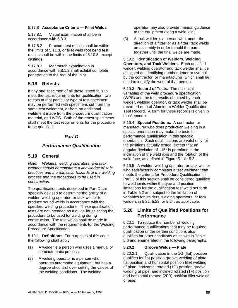
ALUM_WELD_CODE — REV. A — 10 February, 1998 55
5.17.8 Acceptance Criteria — Fillet Welds
5.17.8.1 Visual examination shall be inaccordance with 5.8.3.
5.17.8.2 Fracture test results shall be withinthe limits of 5.11.3, or fillet weld root bend testresults shall be within the limits of 5.10.3, exceptcastings.
5.17.8.3 Macroetch examination inaccordance with 5.8.1.2 shall exhibit completepenetration to the root of the joint.
5.18 Retests
If any one specimen of all those tested fails tomeet the test requirements for qualification, tworetests of that particular type of test specimenmay be performed with specimens cut from thesame test weldment, or from an additionalweldment made from the procedure qualificationmaterial, and WPS. Both of the retest specimensshall meet the test requirements for the procedureto be qualified.
Part D
Performance Qualification
5.19 General
Note: Welders. welding operators, and tackwelders should demonstrate a knowledge of safepractices and the particular hazards of the weldingprocess and the procedures to be used inconstruction.
The qualification tests described in Part D arespecially devised to determine the ability of awelder, welding operator, or tack welder toproduce sound welds in accordance with thespecified welding procedure. These qualificationtests are not intended as a guide for selecting theprocedure to be used for welding duringconstruction. The test welds shall be made inaccordance with the requirements for the WeldingProcedure Specification.
5.19.1 Definitions. For purposes of this codethe following shall apply:
(1) A welder is a person who uses a manual orsemiautomatic process.
(2) A welding operator is a person whooperates automated equipment, but has adegree of control over setting the values ofthe welding conditions. The welding
operator may also provide manual guidanceto the equipment along a weld joint.
(3) A tack welder is a person who, under thedirection of a fitter, or as a fitter, tack weldsan assembly in order to hold the partstogether until the final welds are made.
5.19.2 Identification of Welders, WeldingOperators, and Tack Welders. Each qualifiedwelder, welding operator and tack welder shall beassigned an identifying number, letter or symbolby the contractor or manufacturer, which shall beused to identify the work of that person.
5.19.3 Record of Tests. The essentialvariables of the weld procedure specification(WPS) and the test results obtained by eachwelder, welding operator, or tack welder shall berecorded on a of Aluminum Welder QualificationTest Record. A form for these records is given inthe Appendix.
5.19.4 Special Positions. A contractor ormanufacturer who does production welding in aspecial orientation may make the tests forperformance qualification in this specificorientation. Such qualifications are valid only forthe positions actually tested, except that anangular deviation of ±15° is permitted in theinclination of the weld axis and the rotation of theweld face, as defined in Figure 5.1 or 5.2.
5.19.5 A welder, welding operator, or tack welderwho satisfactorily completes a test weldment thatmeets the criteria for Procedure Qualification inPart C of this section shall be considered qualifiedto weld joints within the type and positionlimitations for the qualification test weld set forthin Table 5.2 and subject to the limitation ofvariables for welders, welding operators, or tackwelders in 5.22, 5.23, or 5.24, as applicable.
5.20 Limits of Qualified Positions forPerformance
5.20.1 To reduce the number of weldingperformance qualifications that may be required,qualification under certain conditions alsoqualifies for other conditions as shown in Table5.6 and enumerated in the following paragraphs.
5.20.2 Groove Welds — Plate
5.20.2.1 Qualification in the 1G (flat) positionqualifies for flat position groove welding of plate,flat position and horizontal position fillet weldingof plate, horizontal rotated (1G) position groovewelding of pipe, and inclined rotated (1F) positionand horizontal rotated (2FR) position fillet weldingof pipe.
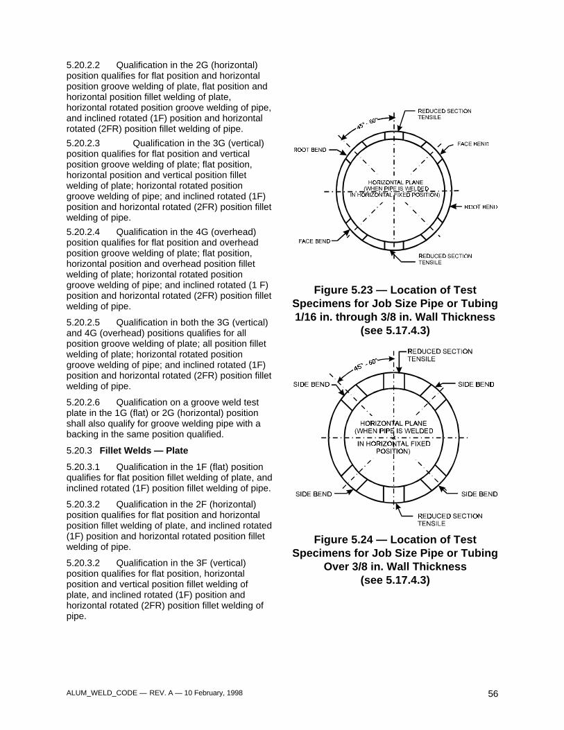
ALUM_WELD_CODE — REV. A — 10 February, 1998 56
5.20.2.2 Qualification in the 2G (horizontal)position qualifies for flat position and horizontalposition groove welding of plate, flat position andhorizontal position fillet welding of plate,horizontal rotated position groove welding of pipe,and inclined rotated (1F) position and horizontalrotated (2FR) position fillet welding of pipe.
5.20.2.3 Qualification in the 3G (vertical)position qualifies for flat position and verticalposition groove welding of plate; flat position,horizontal position and vertical position filletwelding of plate; horizontal rotated positiongroove welding of pipe; and inclined rotated (1F)position and horizontal rotated (2FR) position filletwelding of pipe.
5.20.2.4 Qualification in the 4G (overhead)position qualifies for flat position and overheadposition groove welding of plate; flat position,horizontal position and overhead position filletwelding of plate; horizontal rotated positiongroove welding of pipe; and inclined rotated (1 F)position and horizontal rotated (2FR) position filletwelding of pipe.
5.20.2.5 Qualification in both the 3G (vertical)and 4G (overhead) positions qualifies for allposition groove welding of plate; all position filletwelding of plate; horizontal rotated positiongroove welding of pipe; and inclined rotated (1F)position and horizontal rotated (2FR) position filletwelding of pipe.
5.20.2.6 Qualification on a groove weld testplate in the 1G (flat) or 2G (horizontal) positionshall also qualify for groove welding pipe with abacking in the same position qualified.
5.20.3 Fillet Welds — Plate
5.20.3.1 Qualification in the 1F (flat) positionqualifies for flat position fillet welding of plate, andinclined rotated (1F) position fillet welding of pipe.
5.20.3.2 Qualification in the 2F (horizontal)position qualifies for flat position and horizontalposition fillet welding of plate, and inclined rotated(1F) position and horizontal rotated position filletwelding of pipe.
5.20.3.2 Qualification in the 3F (vertical)position qualifies for flat position, horizontalposition and vertical position fillet welding ofplate, and inclined rotated (1F) position andhorizontal rotated (2FR) position fillet welding ofpipe.
Figure 5.23 — Location of TestSpecimens for Job Size Pipe or Tubing1/16 in. through 3/8 in. Wall Thickness
(see 5.17.4.3)
Figure 5.24 — Location of TestSpecimens for Job Size Pipe or Tubing
Over 3/8 in. Wall Thickness(see 5.17.4.3)
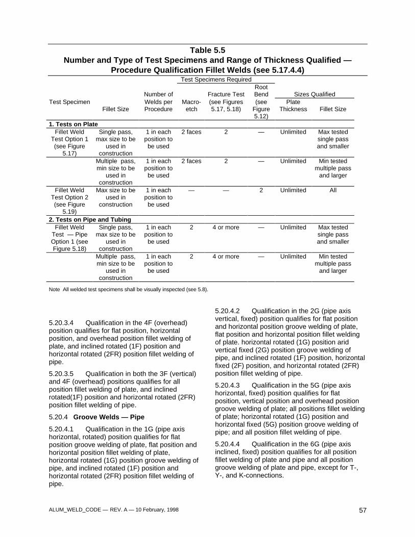
ALUM_WELD_CODE — REV. A — 10 February, 1998 57
Table 5.5Number and Type of Test Specimens and Range of Thickness Qualified —
Procedure Qualification Fillet Welds (see 5.17.4.4)Test Specimens Required
Number of Fracture TestRootBend Sizes Qualified
Test SpecimenFillet Size
Welds perProcedure
Macro-etch
(see Figures5.17, 5.18)
(seeFigure5.12)
PlateThickness Fillet Size
1. Tests on PlateFillet Weld
Test Option 1(see Figure
5.17)
Single pass,max size to be
used inconstruction
1 in eachposition tobe used
2 faces 2 — Unlimited Max testedsingle passand smaller
Multiple pass,min size to be
used inconstruction
1 in eachposition tobe used
2 faces 2 — Unlimited Min testedmultiple pass
and larger
Fillet WeldTest Option 2(see Figure
5.19)
Max size to beused in
construction
1 in eachposition tobe used
— — 2 Unlimited All
2. Tests on Pipe and TubingFillet Weld
Test — PipeOption 1 (seeFigure 5.18)
Single pass,max size to be
used inconstruction
1 in eachposition tobe used
2 4 or more — Unlimited Max testedsingle passand smaller
Multiple pass,min size to be
used inconstruction
1 in eachposition tobe used
2 4 or more — Unlimited Min testedmultiple pass
and larger
Note All welded test specimens shall be visually inspected (see 5.8).
5.20.3.4 Qualification in the 4F (overhead)position qualifies for flat position, horizontalposition, and overhead position fillet welding ofplate, and inclined rotated (1F) position andhorizontal rotated (2FR) position fillet welding ofpipe.
5.20.3.5 Qualification in both the 3F (vertical)and 4F (overhead) positions qualifies for allposition fillet welding of plate, and inclinedrotated(1F) position and horizontal rotated (2FR)position fillet welding of pipe.
5.20.4 Groove Welds — Pipe
5.20.4.1 Qualification in the 1G (pipe axishorizontal, rotated) position qualifies for flatposition groove welding of plate, flat position andhorizontal position fillet welding of plate,horizontal rotated (1G) position groove welding ofpipe, and inclined rotated (1F) position andhorizontal rotated (2FR) position fillet welding ofpipe.
5.20.4.2 Qualification in the 2G (pipe axisvertical, fixed) position qualifies for flat positionand horizontal position groove welding of plate,flat position and horizontal position fillet weldingof plate. horizontal rotated (1G) position aridvertical fixed (2G) position groove welding ofpipe, and inclined rotated (1F) position, horizontalfixed (2F) position, and horizontal rotated (2FR)position fillet welding of pipe.
5.20.4.3 Qualification in the 5G (pipe axishorizontal, fixed) position qualifies for flatposition, vertical position and overhead positiongroove welding of plate; all positions fillet weldingof plate; horizontal rotated (1G) position andhorizontal fixed (5G) position groove welding ofpipe; and all position fillet welding of pipe.
5.20.4.4 Qualification in the 6G (pipe axisinclined, fixed) position qualifies for all positionfillet welding of plate and pipe and all positiongroove welding of plate and pipe, except for T-,Y-, and K-connections.
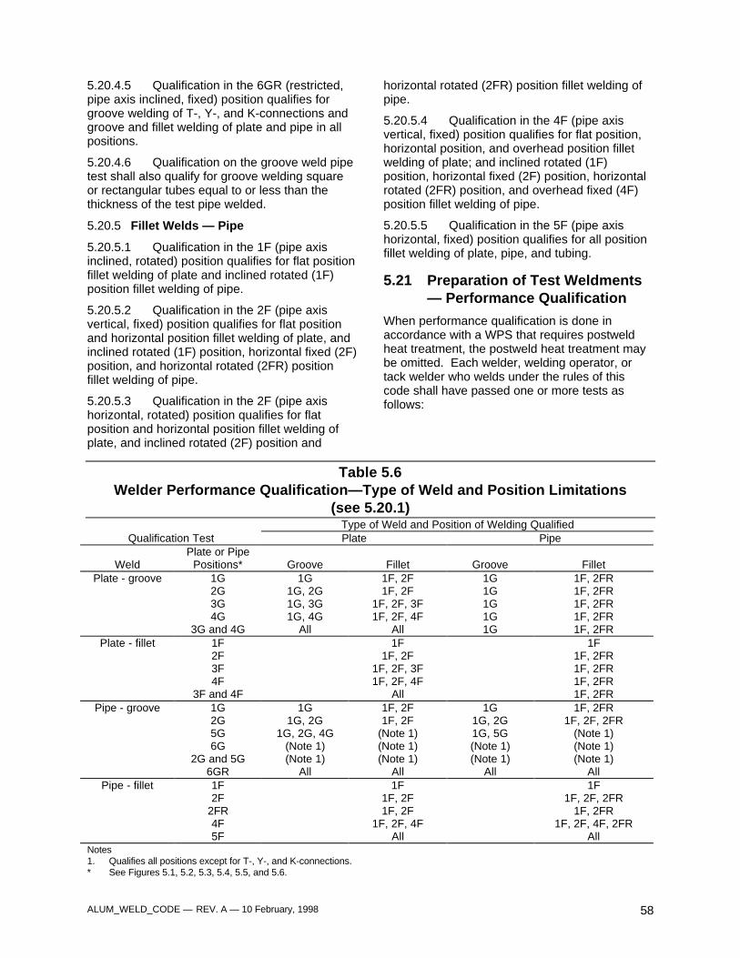
ALUM_WELD_CODE — REV. A — 10 February, 1998 58
5.20.4.5 Qualification in the 6GR (restricted,pipe axis inclined, fixed) position qualifies forgroove welding of T-, Y-, and K-connections andgroove and fillet welding of plate and pipe in allpositions.
5.20.4.6 Qualification on the groove weld pipetest shall also qualify for groove welding squareor rectangular tubes equal to or less than thethickness of the test pipe welded.
5.20.5 Fillet Welds — Pipe
5.20.5.1 Qualification in the 1F (pipe axisinclined, rotated) position qualifies for flat positionfillet welding of plate and inclined rotated (1F)position fillet welding of pipe.
5.20.5.2 Qualification in the 2F (pipe axisvertical, fixed) position qualifies for flat positionand horizontal position fillet welding of plate, andinclined rotated (1F) position, horizontal fixed (2F)position, and horizontal rotated (2FR) positionfillet welding of pipe.
5.20.5.3 Qualification in the 2F (pipe axishorizontal, rotated) position qualifies for flatposition and horizontal position fillet welding ofplate, and inclined rotated (2F) position and
horizontal rotated (2FR) position fillet welding ofpipe.
5.20.5.4 Qualification in the 4F (pipe axisvertical, fixed) position qualifies for flat position,horizontal position, and overhead position filletwelding of plate; and inclined rotated (1F)position, horizontal fixed (2F) position, horizontalrotated (2FR) position, and overhead fixed (4F)position fillet welding of pipe.
5.20.5.5 Qualification in the 5F (pipe axishorizontal, fixed) position qualifies for all positionfillet welding of plate, pipe, and tubing.
5.21 Preparation of Test Weldments— Performance Qualification
When performance qualification is done inaccordance with a WPS that requires postweldheat treatment, the postweld heat treatment maybe omitted. Each welder, welding operator, ortack welder who welds under the rules of thiscode shall have passed one or more tests asfollows:
Table 5.6Welder Performance Qualification—Type of Weld and Position Limitations
(see 5.20.1)Type of Weld and Position of Welding Qualified
Qualification Test Plate Pipe
WeldPlate or Pipe
Positions* Groove Fillet Groove FilletPlate - groove 1G
2G3G4G
3G and 4G
1G1G, 2G1G, 3G1G, 4G
All
1F, 2F1F, 2F
1F, 2F, 3F1F, 2F, 4F
All
1G1G1G1G1G
1F, 2FR1F, 2FR1F, 2FR1F, 2FR1F, 2FR
Plate - fillet 1F2F3F4F
3F and 4F
1F1F, 2F
1F, 2F, 3F1F, 2F, 4F
All
1F1F, 2FR1F, 2FR1F, 2FR1F, 2FR
Pipe - groove 1G2G5G6G
2G and 5G6GR
1G1G, 2G
1G, 2G, 4G(Note 1)(Note 1)
All
1F, 2F1F, 2F
(Note 1)(Note 1)(Note 1)
All
1G1G, 2G1G, 5G(Note 1)(Note 1)
All
1F, 2FR1F, 2F, 2FR
(Note 1)(Note 1)(Note 1)
AllPipe - fillet 1F
2F2FR4F5F
1F1F, 2F1F, 2F
1F, 2F, 4FAll
1F1F, 2F, 2FR
1F, 2FR1F, 2F, 4F, 2FR
AllNotes1. Qualifies all positions except for T-, Y-, and K-connections.* See Figures 5.1, 5.2, 5.3, 5.4, 5.5, and 5.6.
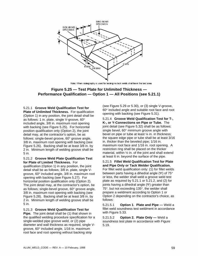
ALUM_WELD_CODE — REV. A — 10 February, 1998 59
Figure 5.25 — Test Plate for Unlimited Thickness —Performance Qualification — Option 1 — All Positions (see 5.21.1)
5.21.1 Groove Weld Qualification Test forPlate of Unlimited Thickness. For qualification(Option 1) in any position, the joint detail shall beas follows: 1 in. plate, single V-groove, 60°included angle, 3/8 in. maximum root openingwith backing (see Figure 5.25). For horizontalposition qualification only (Option 2), the jointdetail may, at the contractor's option, be asfollows: single-bevel groove, 60° groove angle,3/8 in. maximum root opening with backing (seeFigure 5.26). Backing shall be at least 3/8 in. by2 in. Minimum length of welding groove shall be5 in.
5.21.2 Groove Weld Plate Qualification Testfor Plate of Limited Thickness. Forqualification (Option 1) in any position, the jointdetail shall be as follows; 3/8 in. plate, single V-groove, 60° included angle, 3/8 in. maximum rootopening with backing (see Figure 5.27). Forhorizontal position qualification only (Option 2).The joint detail may, at the contractor's option, beas follows; single-bevel groove, 60° groove angle,3/8 in. maximum root opening with backing (seeFigure 5.28). Backing shall be at least 3/8 in. by2 in. Minimum length of welding groove shall be5 in.
5.21.3 Groove Weld Qualification Test forPipe. The joint detail shall be (1) that shown inthe qualified welding procedure specification for asingle-welded pipe groove weld, or (2) pipediameter and wall thickness as required, single V-groove, 60° included angle, 1/16 in. maximumroot face and root opening without backing strip
(see Figure 5.29 or 5.30), or (3) single V-groove,60° included angle and suitable root face and rootopening with backing (see Figure 5.31).
5.21.4 Groove Weld Qualification Test for T-,K-, or Y-Connections on Pipe or Tube. Thejoint detail (see Figure 5.32) shall be as follows:single bevel, 60° minimum groove angle withbevel on pipe or tube at least ¼ in. in thickness;the square edge pipe or tube shall be at least 3/16in. thicker than the beveled pipe; 1/16 in.maximum root face and 1/16 in. root opening. Arestriction ring shall be placed on the thickermaterial, within ½ in. of the joint and shall extendat least 6 in. beyond the surface of the pipe.
5.21.5 Fillet Weld Qualification Test for Plateand Pipe Only or Tack Welder Qualification.For fillet weld qualification only: (1) for fillet weldsbetween parts having a dihedral angle (Ψ) of 75°or less, the welder shall weld a groove weld testplate as required by 5.21.1 or 5.21.2, and (2) forjoints having a dihedral angle (Ψ) greater than75°. but not exceeding 135°, the welder shallprepare a weldment according to Option 1 orOption 2 depending on the contractor's choice, asfollows:
5.21.5.1 Option 1. Plate and Pipe — Weld afillet weld soundness test weldment in accordancewith Figure 5.33.
5.21.5.2 Option 2. Plate Only — Weld asoundness test plate in accordance with Figure5.19.
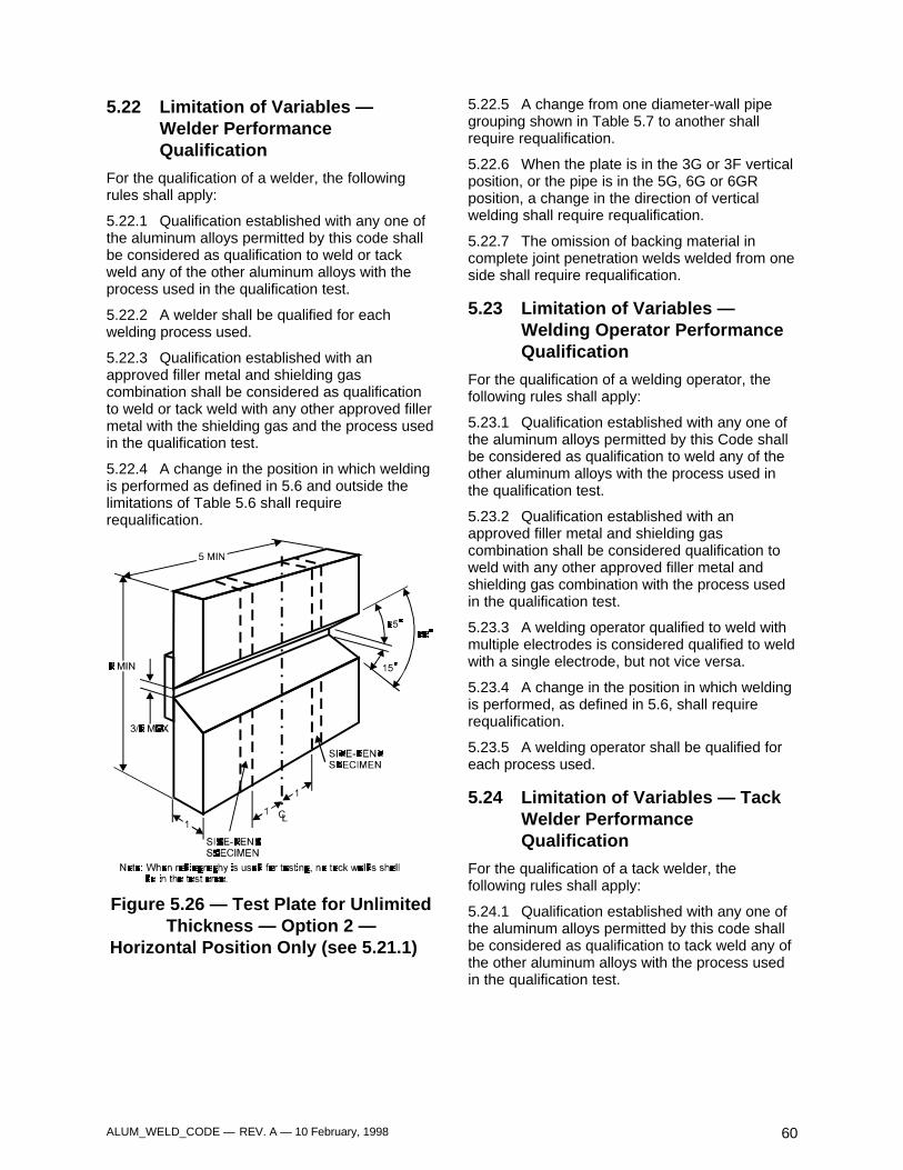
ALUM_WELD_CODE — REV. A — 10 February, 1998 60
5.22 Limitation of Variables —Welder PerformanceQualification
For the qualification of a welder, the followingrules shall apply:
5.22.1 Qualification established with any one ofthe aluminum alloys permitted by this code shallbe considered as qualification to weld or tackweld any of the other aluminum alloys with theprocess used in the qualification test.
5.22.2 A welder shall be qualified for eachwelding process used.
5.22.3 Qualification established with anapproved filler metal and shielding gascombination shall be considered as qualificationto weld or tack weld with any other approved fillermetal with the shielding gas and the process usedin the qualification test.
5.22.4 A change in the position in which weldingis performed as defined in 5.6 and outside thelimitations of Table 5.6 shall requirerequalification.
Figure 5.26 — Test Plate for UnlimitedThickness — Option 2 —
Horizontal Position Only (see 5.21.1)
5.22.5 A change from one diameter-wall pipegrouping shown in Table 5.7 to another shallrequire requalification.
5.22.6 When the plate is in the 3G or 3F verticalposition, or the pipe is in the 5G, 6G or 6GRposition, a change in the direction of verticalwelding shall require requalification.
5.22.7 The omission of backing material incomplete joint penetration welds welded from oneside shall require requalification.
5.23 Limitation of Variables —Welding Operator PerformanceQualification
For the qualification of a welding operator, thefollowing rules shall apply:
5.23.1 Qualification established with any one ofthe aluminum alloys permitted by this Code shallbe considered as qualification to weld any of theother aluminum alloys with the process used inthe qualification test.
5.23.2 Qualification established with anapproved filler metal and shielding gascombination shall be considered qualification toweld with any other approved filler metal andshielding gas combination with the process usedin the qualification test.
5.23.3 A welding operator qualified to weld withmultiple electrodes is considered qualified to weldwith a single electrode, but not vice versa.
5.23.4 A change in the position in which weldingis performed, as defined in 5.6, shall requirerequalification.
5.23.5 A welding operator shall be qualified foreach process used.
5.24 Limitation of Variables — TackWelder PerformanceQualification
For the qualification of a tack welder, thefollowing rules shall apply:
5.24.1 Qualification established with any one ofthe aluminum alloys permitted by this code shallbe considered as qualification to tack weld any ofthe other aluminum alloys with the process usedin the qualification test.
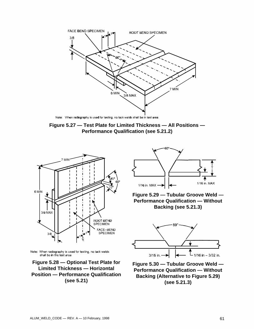
ALUM_WELD_CODE — REV. A — 10 February, 1998 61
Figure 5.27 — Test Plate for Limited Thickness — All Positions —Performance Qualification (see 5.21.2)
Figure 5.28 — Optional Test Plate forLimited Thickness — Horizontal
Position — Performance Qualification(see 5.21)
Figure 5.29 — Tubular Groove Weld —Performance Qualification — Without
Backing (see 5.21.3)
Figure 5.30 — Tubular Groove Weld —Performance Qualification — WithoutBacking (Alternative to Figure 5.29)
(see 5.21.3)
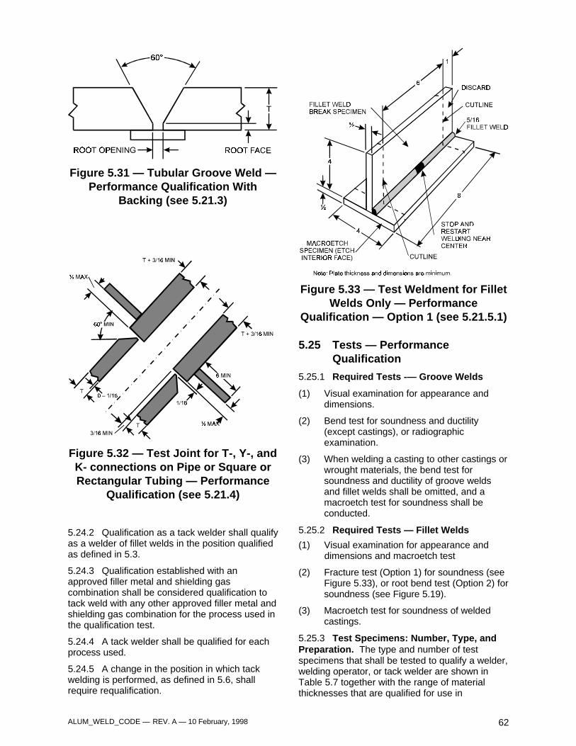
ALUM_WELD_CODE — REV. A — 10 February, 1998 62
Figure 5.31 — Tubular Groove Weld —Performance Qualification With
Backing (see 5.21.3)
Figure 5.32 — Test Joint for T-, Y-, andK- connections on Pipe or Square orRectangular Tubing — Performance
Qualification (see 5.21.4)
5.24.2 Qualification as a tack welder shall qualifyas a welder of fillet welds in the position qualifiedas defined in 5.3.
5.24.3 Qualification established with anapproved filler metal and shielding gascombination shall be considered qualification totack weld with any other approved filler metal andshielding gas combination for the process used inthe qualification test.
5.24.4 A tack welder shall be qualified for eachprocess used.
5.24.5 A change in the position in which tackwelding is performed, as defined in 5.6, shallrequire requalification.
Figure 5.33 — Test Weldment for FilletWelds Only — Performance
Qualification — Option 1 (see 5.21.5.1)
5.25 Tests — PerformanceQualification
5.25.1 Required Tests -— Groove Welds
(1) Visual examination for appearance anddimensions.
(2) Bend test for soundness and ductility(except castings), or radiographicexamination.
(3) When welding a casting to other castings orwrought materials, the bend test forsoundness and ductility of groove weldsand fillet welds shall be omitted, and amacroetch test for soundness shall beconducted.
5.25.2 Required Tests — Fillet Welds
(1) Visual examination for appearance anddimensions and macroetch test
(2) Fracture test (Option 1) for soundness (seeFigure 5.33), or root bend test (Option 2) forsoundness (see Figure 5.19).
(3) Macroetch test for soundness of weldedcastings.
5.25.3 Test Specimens: Number, Type, andPreparation. The type and number of testspecimens that shall be tested to qualify a welder,welding operator, or tack welder are shown inTable 5.7 together with the range of materialthicknesses that are qualified for use in

ALUM_WELD_CODE — REV. A — 10 February, 1998 63
construction in relation to the thickness of the testmaterial used in making the qualification.Radiographic examination of the groove-weld testassembly may be used at the contractor's optionin lieu of mechanical testing, see section 6, Part Bfor specific radiation angle, dimensions andmacroetch test.
5.25.4 Location of Test Specimens forPerformance Qualification. One sampleweldment shall be made for the type of weldqualification being tested. Test size of thesample weldment and location of the testspecimens to be removed shall be in accordancewith the figures associated with the type ofweldment being tested (see Figures 5.25 through5.33). The removal of test specimens from pipeshall be as shown in Figure 5.34.
5.25.5 Preparation of Test Specimens. Thetest specimens shall be prepared in accordancewith section 5, Part B.
5.25.6 Test Procedures
5.25.6.1 Bend tests shall be made asdescribed in 5.10.2.
5.25.6.2 Fillet Weld Fracture Test. Theentire length of the fillet weld shall be examinedvisually; then the 6 in. long specimen shall betested as described in 5.25.2.
5.25.6.3 Radiographic test procedure shall beas described in section 6, Part B.
5.25.6.4 Macroetch test procedure isdescribed in 5.8.1.2.
5.25.7 Acceptance Criteria — Groove Welds
5.25.7.1 Visual examination shall conform to5.8.2.
5.25.7.2 Guided bend test results shall bewithin the limits of 5.10.3.
5.25.7.3 Radiographic evaluation shall bewithin the limits of 5.12.2. Two radiographs shallbe taken, one perpendicular to the weld surface,and the second parallel to one side of the weldgroove.
5.25.8 Acceptance Criteria — Fillet Welds
5.25.8.1 Visual examination shall conform to5.8.3.
5.25.8.2 Fracture test results shall be withinthe limits of 5.11.3.1.
5.25.8.3 Fillet weld root bend test results shallbe within the limits of 5.10.3.
5.26 Retests
5.26.1 The performance test may be terminatedat any stage of the testing procedure, whenever itbecomes apparent to the supervisor conductingthe tests that the welder, welding operator, or tackwelder does not have the required skill to producesatisfactory results.
5.26.2 In case a welder, welding operator or tackwelder fails to meet the requirements of one ormore weld tests, a retest may be allowed underthe following conditions:
5.26.2.1 An immediate retest may be madeconsisting of two test specimens of each type onwhich the welder, welding operator, or tack welderfailed. All retest specimens shall meet all thespecified requirements.
5.26.2.2 A complete performance qualificationretest may be made at a later date for any failedqualification tests provided, there is evidence thatthe welder, welding operator, or tack welder hashad further training or practice.
5.27 Period of Effectiveness
The welder's, welding operator's, or tack welder'squalification, as specified in this code (Section 5,
Part D), shall be considered as remaining ineffect indefinitely unless (1) the welder, weldingoperator, or tack welder is not engaged in a givenprocess of welding for which the welder, weldingoperator, or tack welder is qualified for a periodexceeding, six months, or (2) there is somespecific reason to question the welder's, weldingoperator's, or tack welder's ability.
Footnotes
1. The provisions of ANSI/AWS B2.1, Standard for WeldingProcedures and Performance Qualification, may be used forthe qualification of procedures and personnel. However, ininstances where the provisions of ANSl/AWS B2.1 andANSI/AWS D1.2 are in conflict, ANSI/AWS D1.2 shall takeprecedence.
2. The term pipe as used herein shall include all tubularshapes.
3. The provisions of ANSI/AWS B4.0, Standard Methods forMechanical Testing of Welds, may be used for the testingof welds made for procedure or performance qualification.However, in instances where the provisions of ANSI/AWSB4.0 and ANSI/AWS D1.2 are in conflict, ANSI/AWS D1.2should take precedence.
4. Annealing practice: Hold 2 – 3 hours at 775°F and cool at50° F/hr to 500°F. The rate of cooling below 500º F isunimportant.
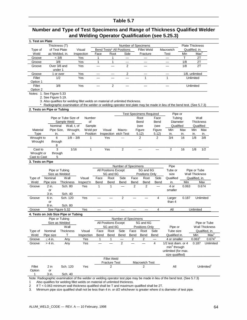
ALUM_WELD_CODE — REV. A — 10 February, 1998 64
Table 5.7
Number and Type of Test Specimens and Range of Thickness Qualified Welderand Welding Operator Qualification (see 5.25.3)
1. Test on PlateThickness (T) Number of Specimens Plate Thickness
Type of of Test Plate Visual Bend Tests* All Positions Fillet Weld Macroetch Qualified, in.Weld as Welded, in. Inspection Face Root Side Fracture Test Min Max3
Groove < 3/8 Yes 1 1 — — — T 2TGroove 3/8 Yes 1 1 — — — 1/8 2TGroove Over 3/8 and
under 1Yes — — 2 — — 1/8 2T
Groove 1 or over Yes — — 2 — — 1/8, unlimitedFillet
Option 11/2 Yes — — — 1 1 Unlimited
FilletOption 2
3/8 Yes — 2 — — — Unlimited
Notes: 1. See Figure 5.332. See Figure 5.19.3. Also qualifies for welding fillet welds on material of unlimited thickness.* Radiographic examination of the welder or welding operator test plate may be made in lieu of the bend test. (See 5.7.3)
2. Tests on Pipe or TubingTest Specimens Required Pipe or
Pipe or Tube Size of Number Root Face Tubing WallSample Weld of Bend Bend Diameter Thickness
Nominal Wall, t, of Sample (see (see Qualified QualifiedMaterial
TypePipe Size,
in.Wrought,
in.Weld perPosition
VisualInspection
Macro-etch Test
Figure5.12)
Figure5.12)
Minin.
Maxin.
Minin.
Maxin.
Wrought toWrought
6through
8
1/8 – 3/8 1 Yes — 2 2 3/4 16 1/8 3/8
Cast toWrought orCast to Cast
3through
5
1/16 1 Yes 2 — — 2 16 1/8 1/2
3. Tests on PipeNumber of Specimens Pipe
Pipe or Tubing All Positions Except 5G and 6G Tube or Pipe or TubeSize as Welded 5G and 6G Positions Only size Wall Thickness
Type of Nominal Wall Visual Face Root Side Face Root Side Qualified Qualified, in.Weld Pipe size Thickness Inspect’n Bend Bend Bend Bend Bend Bend in. Min Max
Groove 2 in.or
3 in.
Sch. 80
Sch. 40
Yes 1 1 — 2 2 — 4 orsmaller
0.063 0.674
Groove 6 in.or
8 in.
Sch. 120
Sch. 80
Yes — — 2 — — 4 Largerthan 4
0.187 Unlimited
Groove See Figure 5.32 Yes — — — — — 4 All Unlimited
4. Tests on Job Size Pipe or TubingPipe or Tubing Number of SpecimensSize as Welded All Positions Except 5G and 6G Pipe or Tube
Wall 5G and 6G Positions Only Pipe or Wall ThicknessType of Nominal Thickness Visual Face Root Side Face Root Side Tube size Qualified, in.Weld Pipe size T Inspection Bend Bend Bend Bend Bend Bend Qualified in. Min Max1
Groove ≤ 4 in. Any Yes 1 1 — 2 2 — 4 or smaller 0.0631 0.6741
Groove > 4 in. Any Yes — — 2 — — 4 1/2 test diam. or 4min3 through
unlimited (for max.size qualified)
0.187 Unlimited
Fillet WeldFracture Test Macroetch Test
FilletOption
1
2 inor
3 in.
Sch. 120
Sch. 40
Yes 2 2 All Unlimited1
Note: Radiographic examination of the welder or welding operator test pipe may be made in lieu of the bend test. (See 5.7.3)1 Also qualifies for welding fillet welds on material of unlimited thickness.2 If T < 0.063 minimum wall thickness qualified shall be T and maximum qualified shall be 2T.3. Minimum pipe size qualified shall not be less than 4 in. or d/2 whichever is greater where d is diameter of test pipe.
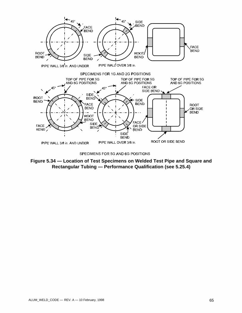
ALUM_WELD_CODE — REV. A — 10 February, 1998 65
Figure 5.34 — Location of Test Specimens on Welded Test Pipe and Square andRectangular Tubing — Performance Qualification (see 5.25.4)

ALUM_WELD_CODE — REV. A — 10 February, 1998 66

ALUM_WELD_CODE — REV. A — 10 February, 1998 67
6. InspectionPart A
General Requirements
6.1 General6.1.1 For the purpose of this Code, fabricationverification and testing and confirmation andtesting are separate functions. Fabricationverification and testing may be performed asnecessary prior to assembly, during assembly,during welding, and after welding to ensure thatmaterial and workmanship meet the requirementsof the contract document. Confirmation inspectionand testing shall be performed in a timely mannerto avoid delays in the work. Fabricationverification and testing shall be the responsibilityof the manufacturer, unless otherwise provided inthe contract documents. Confirmation inspectionand testing may be performed at the prerogativeof the contracting agency.
6.1.2 The fabrication verification and testingindividual is one who performs verification andtesting in regard to product quality on behalf ofthe manufacturer within the scope of the contractdocument. The confirmation individual acts onbehalf of the contracting agency on all qualitymatters within the scope of the contractdocument.
When the term Inspector(s) is used in this Codewithout further qualification, it applies equally tothe individual performing fabrication verificationand confirmation within the limits of 6.1.1.
6.1.3 Inspector Qualification
6.1.3.1 Inspectors responsible for acceptanceor rejection of material and workmanship shall bequalified. The basis of Inspector qualification shallbe documented.
The following are acceptable qualification bases:
(1) Current or previous certification as an AWSCertified Welding Inspector (CWI) inaccordance with the provisions of AWSQCI, Standard and Guide for Qualificationand Certification of Welding Inspectors, or
(2) Current or previous qualification by theCanadian Welding Bureau (CWB) to therequirements of the Canadian StandardAssociation (CSA) Standard W178.2,Certification of Welding Inspectors, or
(3) An Engineer, technician or operator who, bytraining and experience, in metalsfabrication, inspection, and testing, iscompetent to perform inspection of thework, as described in this document.
6.1.3.2 The qualification of an Inspector shallremain in effect indefinitely, provided theInspector remains active in inspection of weldedaluminum fabrication, unless there is specificreason to question the Inspector's ability.
6.1.3.4 Inspectors shall have passed an eyeexamination with or without corrective lenses toprove: (1) near vision acuity of Snellen English, orequivalent, at no less than12 in., and (2) far visionacuity of 20/40, or better. An eye examination ofall inspection personnel is required every threeyears or less, if necessary, to demonstrateadequacy.
6.1.3.5 Weld Engineering and/or QualityEngineering shall have authority to verify thequalification of Inspectors.
6.1.4 The Inspector shall ascertain that allfabrication and erection by welding is performedin accordance with the requirements of thecontract documents.
6.1.5 The Inspector shall be furnishedcomplete, detailed weld drawings showing thesize, length, type, and location as well as allneeded inspection documents.
6.1.6 The Inspector shall be notified ofoperations subject to inspection and verification.
6.2 Inspection of Materials
The Inspector shall make certain that onlymaterials conforming to the requirements of thisCode are used.
6.3 Inspection of WeldingProcedure Qualification andEquipment
6.3.1 The Inspector shall make certain that allwelding is in accordance with a welding procedurespecification which has been qualified inaccordance with 5.2 of this Code.
6.3.2 The Inspector shall assure that thewelding equipment to be used conforms to therequirements of 3.1.2.
ALUM_WELD_CODE — REV. A — 10 February, 1998 68
6.4 Inspection of Welder, WeldingOperator, and Tack WelderQualifications
6.4.1 The contractor shall permit welding to beperformed only by welders, welding operators,and tack welders who are qualified in accordancewith the requirements of 5.3.
6.4.2 When the quality of a welder's, weldingoperator's, or tack welder's work appears to bebelow the requirements of this Code, theInspector shall determine the cause and mayrequire that the welder, welding operator, or tackwelder demonstrate an ability to produce soundwelds by means of a simple test, such as the filletweld break test or by requiring completerequalification in accordance with section 5, PartD.
6.4.3 The Inspector shall require requalificationof any welder, welding operator, or tack welderwho has not used each process to be used in theconstruction under consideration for a periodexceeding six months.
6.5 Inspection of Work and Records
6.5.1 As part of the visual inspection, theInspector shall make certain that the size, length,and location of all welds conform to therequirements of this Code, and to the detaildrawings, and that no unspecified welds havebeen added without approval.
6.5.2 The Inspector shall make certain that onlywelding procedures which meet the provisions of5.1 and 5.2 are employed.
6.5.3 The Inspector shall, observe thetechnique and performance of each welder,welding operator, and tack welder to make certainthat the applicable requirements of section 4 aremet.
6.5.4 The Inspector shall examine the work tomake certain that it meets the requirements ofsection 3 and subsections 8.7, 9.7, or 10.8, asapplicable. The size and contour of welds shall bemeasured with acceptable gages. Visualinspection for cracks in welds and base metal andother discontinuities should be aided by a stronglight, magnifiers, or such other devices as may befound helpful.
6.5.5 The Inspector shall identify with adistinguishing mark all parts or joints that havebeen inspected and rejected.
6.5.6 The Contractor or manufacturer shallkeep a record of qualifications of all welders,welding operators, and tack welders, all procedurequalifications or other tests that are made, andsuch other information as may be pertinent.
6.6 Obligations of the Contractor6.6.1 In addition to the requirements of 6.1.1,the contractor shall be responsible for visualinspection and necessary correction of alldeficiencies in materials and workmanship inaccordance with the requirements of section 3and subsection 8.7.1, 9.7.1, or 10.8.1, asapplicable.
6.6.2 The contractor shall comply with allrequests of the Inspector to correct deficiencies inmaterials and workmanship as provided in thecontract documents.
6.6.3 If faulty welding or its removal forrewelding damages the base metal so that in thejudgment of the MRB its retention is not inaccordance with the intent of the contractdocuments, the contractor shall remove andreplace the damaged base metal in a mannerapproved by the MRB.
6.6.4 When nondestructive testing other thanvisual inspection is specified in the informationfurnished to bidders, it shall be the contractor'sresponsibility to ensure that all specified weldsmeet the quality requirements of 8.7, 9.7, or 10.8,whichever is applicable.
6.7 Nondestructive Testing6.7.1 When nondestructive testing other thanvisual is to be required, it shall be so stated in theprocurement documentation. This informationshall designate the categories of welds to beexamined, the extent of examination of eachcategory, and the method or methods of testing.
6.7.2 Welds tested nondestructively that do notmeet the requirements of this Code shall berepaired by the methods permitted in 3.6.
6.7.3 When radiographic testing is used, theprocedure and technique shall be in accordancewith Part B of this section.
6.7.4 When ultrasonic testing is used, theprocedure and technique shall be in accordancewith Part C of this section.
6.7.5 For detecting discontinuities that are opento the surface, liquid penetrant inspection may beused. The methods set forth in ASTM E165,Standard Recommended Practice for LiquidPenetrant Inspection Method, shall be used and
ALUM_WELD_CODE — REV. A — 10 February, 1998 69
the standards of acceptance shall be inaccordance with 8.7.1, 9.7.1, or 10.8.1, whicheveris applicable.
6.7.6 Personnel Qualification
6.7.6.1 Personnel performing nondestructivetesting other than visual shall be qualified inaccordance with the current edition of theAmerican Society for Nondestructive TestingRecommended Practice No. SNT-TC-1A1. Onlyindividuals a) qualified as an NDT Level II orLevel III, or b) qualified as an NDT Level I andworking under a qualified NDT Level II or Level IIImay perform nondestructive testing unlessotherwise specified.
6.7.6.2 Certification of Level I and Level IIindividuals shall be performed by a Level IIIindividual who has been certified by (1) TheAmerican Society for Nondestructive Testing, or(2) has the education, training, experience, andhas successfully passed the written examinationprescribed in SNT-TC-1A
6.7.6.3 Personnel performing nondestructivetests under the provisions of 6.7.6 need not bequalified nor certified under the provisions ofAWS QCI.
Part B
Radiographic Inspection
6.8 General
6.8.1 The procedures and standards set forthherein govern radiographic testing of welds whensuch inspection is required by the contractdocuments as provided in 6.7. The requirementslisted herein are specifically for testing welds inplates, shapes, and bars by X-ray or gamma-raysources. The methodology shall conform toASTM
E94, Standard Recommended Practice forRadiographic Testing, and ASTM E142, StandardMethod for Controlling Quality of RadiographicTesting, except as provided herein.
6.8.2 Variations in testing procedures,equipment, and acceptance standards shall beused upon agreement between the contractor andthe Government. Such variations include, but arenot limited to, the following: radiographic testingof fillet, T, and corner welds; changes in source-to-film distance; unusual application of film;
unusual penetrameter applications (including filmside penetrameters and wire penetrameters);radiographic testing of thicknesses greater than 6in.; film types, densities, and variations inexposure, development, and view techniques.
6.9 Extent of Testing
The extent of radiographic testing shall be asspecified in the technical data package.Sampling plans shall be submitted to theprocuring activity for approval.
6.10 Radiographic Procedures
6.10.1 Radiographs shall be made using a singlesource of either X-ray or gamma radiation. Theradiographic sensitivity shall be judged on thebasis of the penetrameter images. Theradiographic technique and equipment shallprovide sufficient sensitivity to clearly delineatethe required penetrameters and the essentialholes as described in 6.10.7, Table 6.1 and Figure6.3. Identifying letters and numbers shall showclearly in the radiograph.
6.10.2 Radiography shall be performed inaccordance with all applicable safetyrequirements.
6.10.3 When the technical data packagerequires the removal of weld reinforcement, thewelds shall be prepared for radiography bygrinding as described in 3.5. Other weld surfacesneed not be ground or otherwise smoothed forpurposes of radiographic testing unless surfaceirregularities between the weld and base metalobscure objectionable weld discontinuities.
6.10.3.1 Extension bars and run off platesshall be removed prior to radiographic inspectionunless otherwise approved by the Weld or QualityEngineer.
6.10.3.2 When required by the technical datapackage, backing shall be removed and thesurface shall be finished flush by mechanicalmeans prior to radiography. Weld finishing shallbe as described in 3.5.
6.10.3.2 When weld reinforcement or backing,or both are not removed, aluminum shims whichextend at least 1/8 in. beyond three sides of therequired penetrameter shall be placed under thepenetrameter so that the total thickness ofaluminum between the penetrameter and the film
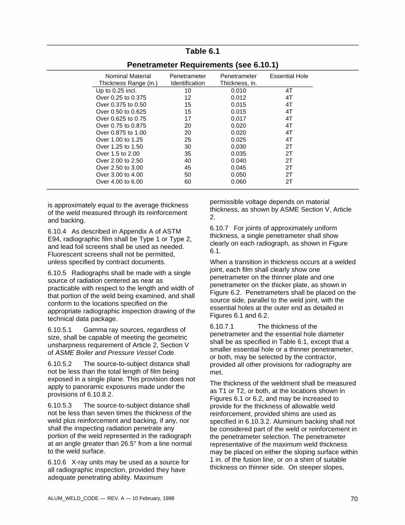
ALUM_WELD_CODE — REV. A — 10 February, 1998 70
Table 6.1
Penetrameter Requirements (see 6.10.1)Nominal Material
Thickness Range (in.)PenetrameterIdentification
PenetrameterThickness, in.
Essential Hole
Up to 0.25 incl. 10 0.010 4TOver 0.25 to 0.375 12 0.012 4TOver 0.375 to 0.50 15 0.015 4TOver 0.50 to 0.625 15 0.015 4TOver 0.625 to 0.75 17 0.017 4TOver 0.75 to 0.875 20 0.020 4TOver 0.875 to 1.00 20 0.020 4TOver 1.00 to 1.25 25 0.025 4TOver 1.25 to 1.50 30 0.030 2TOver 1.5 to 2.00 35 0.035 2TOver 2.00 to 2.50 40 0.040 2TOver 2.50 to 3.00 45 0.045 2TOver 3.00 to 4.00 50 0.050 2TOver 4.00 to 6.00 60 0.060 2T
is approximately equal to the average thicknessof the weld measured through its reinforcementand backing.
6.10.4 As described in Appendix A of ASTME94, radiographic film shall be Type 1 or Type 2,and lead foil screens shall be used as needed.Fluorescent screens shall not be permitted,unless specified by contract documents.
6.10.5 Radiographs shall be made with a singlesource of radiation centered as near aspracticable with respect to the length and width ofthat portion of the weld being examined, and shallconform to the locations specified on theappropriate radiographic inspection drawing of thetechnical data package.
6.10.5.1 Gamma ray sources, regardless ofsize, shall be capable of meeting the geometricunsharpness requirement of Article 2, Section Vof ASME Boiler and Pressure Vessel Code.
6.10.5.2 The source-to-subject distance shallnot be less than the total length of film beingexposed in a single plane. This provision does notapply to panoramic exposures made under theprovisions of 6.10.8.2.
6.10.5.3 The source-to-subject distance shallnot be less than seven times the thickness of theweld plus reinforcement and backing, if any, norshall the inspecting radiation penetrate anyportion of the weld represented in the radiographat an angle greater than 26.5° from a line normalto the weld surface.
6.10.6 X-ray units may be used as a source forall radiographic inspection, provided they haveadequate penetrating ability. Maximum
permissible voltage depends on materialthickness, as shown by ASME Section V, Article2.
6.10.7 For joints of approximately uniformthickness, a single penetrameter shall showclearly on each radiograph, as shown in Figure6.1.
When a transition in thickness occurs at a weldedjoint, each film shall clearly show onepenetrameter on the thinner plate and onepenetrameter on the thicker plate, as shown inFigure 6.2. Penetrameters shall be placed on thesource side, parallel to the weld joint, with theessential holes at the outer end as detailed inFigures 6.1 and 6.2.
6.10.7.1 The thickness of thepenetrameter and the essential hole diametershall be as specified in Table 6.1, except that asmaller essential hole or a thinner penetrameter,or both, may be selected by the contractor,provided all other provisions for radiography aremet.
The thickness of the weldment shall be measuredas T1 or T2, or both, at the locations shown inFigures 6.1 or 6.2, and may be increased toprovide for the thickness of allowable weldreinforcement, provided shims are used asspecified in 6.10.3.2. Aluminum backing shall notbe considered part of the weld or reinforcement inthe penetrameter selection. The penetrameterrepresentative of the maximum weld thicknessmay be placed on either the sloping surface within1 in. of the fusion line, or on a shim of suitablethickness on thinner side. On steeper slopes,
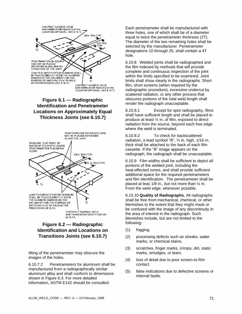
ALUM_WELD_CODE — REV. A — 10 February, 1998 71
Figure 6.1 — RadiographicIdentification and Penetrameter
Locations on Approximately EqualThickness Joints (see 6.10.7)
Figure 6.2 — RadiographicIdentification and Locations onTransitions Joints (see 6.10.7)
tilting of the penetrameter may obscure theimages of the holes.
6.10.7.2 Penetrameters for aluminum shall bemanufactured from a radiographically similaraluminum alloy and shall conform to dimensionsshown in Figure 6.3. For more detailedinformation, ASTM E142 should be consulted.
Each penetrameter shall be manufactured withthree holes, one of which shall be of a diameterequal to twice the penetrameter thickness (2T).The diameter of the two remaining holes shall beselected by the manufacturer. Penetrameterdesignations 10 through 25, shall contain a 4Thole.
6.10.8 Welded joints shall be radiographed andthe film indexed by methods that will providecomplete and continuous inspection of the jointwithin the limits specified to be examined. Jointlimits shall show clearly in the radiographs. Shortfilm, short screens (when required by theradiographic procedure), excessive undercut byscattered radiation, or any other process thatobscures portions of the total weld length shallrender the radiograph unacceptable.
6.10.8.1 Except for spot radiography, filmsshall have sufficient length and shall be placed toproduce at least ½ in. of film, exposed to directradiation from the source, beyond each free edgewhere the weld is terminated.
6.10.8.2 To check for backscatteredradiation, a lead symbol "B", ½ in. high, 1/16 in.thick shall be attached to the back of each filmcassette. If the "B" image appears on theradiograph, the radiograph shall be unacceptable.
6.10.9 Film widths shall be sufficient to depict allportions of the welded joint, including theheat-affected zones, and shall provide sufficientadditional space for the required penetrametersand film identification. The penetrameter shall beplaced at leas 1/8 in., but not more than ¼ in.From the weld edge, whenever possible.
6.10.10 Quality of Radiographs. All radiographsshall be free from mechanical, chemical, or otherblemishes to the extent that they might mask orbe confused with the image of any discontinuity inthe area of interest in the radiograph. Suchblemishes include, but are not limited to thefollowing:
(1) fogging.
(2) processing defects such as streaks, watermarks, or chemical stains.
(3) scratches, finger marks, crimps, dirt, staticmarks, smudges, or tears.
(4) loss of detail due to poor screen-to-filmcontact.
(5) false indications due to defective screens orinternal faults.
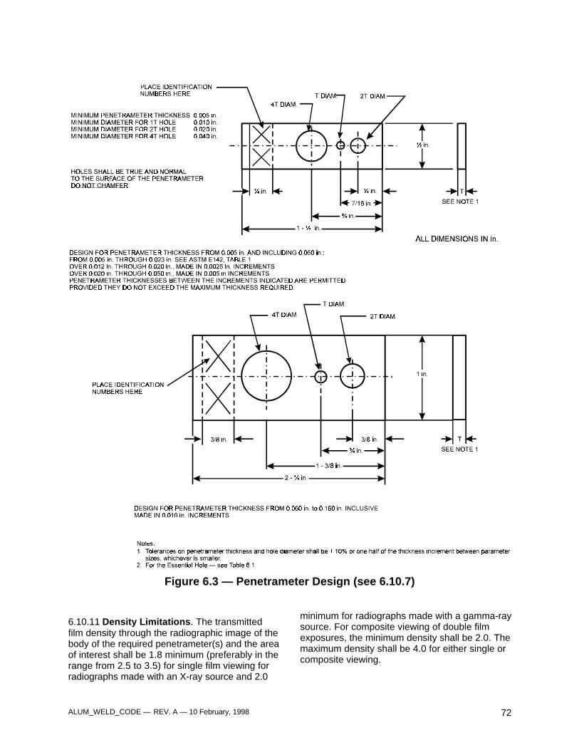
ALUM_WELD_CODE — REV. A — 10 February, 1998 72
Figure 6.3 — Penetrameter Design (see 6.10.7)
6.10.11 Density Limitations. The transmittedfilm density through the radiographic image of thebody of the required penetrameter(s) and the areaof interest shall be 1.8 minimum (preferably in therange from 2.5 to 3.5) for single film viewing forradiographs made with an X-ray source and 2.0
minimum for radiographs made with a gamma-raysource. For composite viewing of double filmexposures, the minimum density shall be 2.0. Themaximum density shall be 4.0 for either single orcomposite viewing.
ALUM_WELD_CODE — REV. A — 10 February, 1998 73
The film shall be processed to develop a filmblackening measured by the H&D radiographicdensity expressed as:
D = H&D (radiographic)density = log10 (I0/I)where
I0 = light intensity on the film, andI = light transmitted through the film
6.10.12 Radiograph identification and locationidentification marks shall be placed on theweldment at each radiograph location, all of whichshall show in the radiograph. The radiographicimages shall be produced by placing leadnumbers or letters, or any combination thereof,over each of the identical identification andlocation marks made on the weldment. Theimages provide the means for matching thedeveloped radiograph with the weld.
Additional identification information may bepreprinted no less than ¾ in. from the edge of theweld or produced on the radiograph by placinglead figures on the weldment.
Information required to show on the radiographshall include the contract identification, initial ofthe radiographic inspection company, initials ofthe fabricator, the fabricator shop order number,the radiographic identification mark, the date, andthe weld repair number, if applicable.
6.11 Acceptability of Welds
Welds shown by radiographic testing to havediscontinuities prohibited by 9.7.2 or 10.8.2 shallbe discarded or corrected in accordance with 3.6.More dense inclusions shall be treated asporosity.
6.12 Examination, Report, andDisposition of Radiographs
6.12.1 The contractor or manufacturer shallmaintain a record of the welds or portions ofwelds subjected to radiographic inspection and
include descriptions, pictures, or sketches of thediscontinuity indications developed.
6.12.2 The contractor shall provide a variableintensity illuminator (viewer) with spot-review ormasked spot-review capability. The viewer shallincorporate a means for adjusting the size of thespot under examination. The viewer shall havesufficient capacity to properly illuminateradiographs with an H&D density of 4.0. Filmreview shall be done in an area of subdued light.
6.12.3 Before a weld subject to radiographictesting by the manufacturer is accepted by thecontractor, all of its radiographs, including anythat show unacceptable quality prior to repair, anda report interpreting them, shall be submitted tothe contractor upon request.
6.12.4 The contractor's or manufacturer’sobligation to retain radiographs shall cease after 1year after completion of the contract unlessotherwise specified.
Part C
Ultrasonic Testing of Groove Welds
6.13 General
6.13.1 When ultrasonic testing is required orpermitted by the Contract Documents, the extentof testing, the procedure, and the acceptancecriteria shall be specified therein.
6.13.2 The tester shall maintain a record of thewelds or portions of welds subjected to ultrasonictesting. The contractor's obligation to retain theserecords shall cease after 5 years after completionof the contract unless otherwise specified.
Footnotes:
1. Available from the American Society for NondestructiveTesting, 4153 Arlingate Plaza, Columbus, Ohio 43228.

ALUM_WELD_CODE — REV. A — 10 February, 1998 74

ALUM_WELD_CODE — REV. A — 10 February, 1998 75
7. Stud Welding
Part A
General Requirements
7.1 General
7.1.1 Section 7 contains general requirementsfor arc stud welding and capacitor discharge studwelding of aluminum alloy studs to aluminumalloys and stipulates specific requirements for thefollowing:
(1) mechanical properties of aluminum alloystuds
(2) workmanship, preproduction testing,qualification, and performance testing
(3) inspection of stud welding duringproduction.
7.1.2 Wherever the term “contractor” is used itmeans “contractor or supplier subject tocontractor’s approval.”
7.1.3 In all drawings subsequent to this code,the weld shall be noted on the technical datapackage as follows: “Weld in accordance withUDLP/TACOM Ground Combat Vehicle WeldingCode -- Aluminum, Section 7.”
Part B
Arc Stud Welding
7.2 General Requirements
7.2.1 Studs shall be ¼ in. up to and including ½in. diameter and designed for arc welding toaluminum members with the use of automaticallytimed stud welding equipment. The type, size,and lengths of the stud shall be as specified bythe drawings, specifications or special provisions.
7.2.2 A ferrule or arc shield of heat resistantceramic or other suitable material shall befurnished with each stud.
7.2.3 The minimum base metal thickness forarc stud application shall not be less than 50% ofthe stud diameter.
7.3 Material Requirements
7.3.1 Studs shall be made from cold drawn orextruded stock of alloys shown below. Otheralloys may be used when specified in thetechnical data package.
Aluminum AlloysFor Arc Stud Welding Applications
4043518353565556
7.3.2 The stud shall not be anodized, painted,or coated with any foreign substance.
7.3.3 The contractor or manufacturer shallhave a method of verification (purchase order,packing slip, etc.) that provides evidence thatstuds conform to 7.3
7.3.4 Mechanical testing of aluminum studalloys shall be in accordance with the applicablesections of ASTM B557, Standard Methods ofTension Testing Wrought and Cast Aluminum-and Aluminum-Alloys and Magnesium-AlloyProducts or AWS B4.0, Standard Methods forMechanical Testing of Welds.
7.4 Workmanship7.4.1 Studs shall be free from oil, moisture,excessive oxide, or other deleterious matter thatwould adversely affect the welding operation.
7.4.2 Base metal to which studs are to bewelded shall be free of anodic coatings, moisture,or other injurious material to assure obtainingsound welds. These areas may be cleaned byetching, brushing with a stainless steel bristlebrush, scraping, or grinding.
7.4.3 Ferrules shall be clean and dry. Anyferrules which show signs of surface moistureshall be oven dried at 250°F for a minimum oftwo hours before use.
7.4.4 Ferrule geometry shall conform to thecontour of the base metal.
7.4.5 Ferrules shall be broken free from allstuds after welding.
7.4.6 Welded studs shall meet the visualinspection requirements of 7.8.
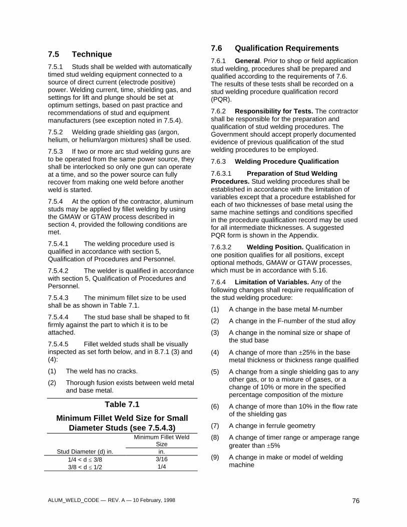
ALUM_WELD_CODE — REV. A — 10 February, 1998 76
7.5 Technique
7.5.1 Studs shall be welded with automaticallytimed stud welding equipment connected to asource of direct current (electrode positive)power. Welding current, time, shielding gas, andsettings for lift and plunge should be set atoptimum settings, based on past practice andrecommendations of stud and equipmentmanufacturers (see exception noted in 7.5.4).
7.5.2 Welding grade shielding gas (argon,helium, or helium/argon mixtures) shall be used.
7.5.3 If two or more arc stud welding guns areto be operated from the same power source, theyshall be interlocked so only one gun can operateat a time, and so the power source can fullyrecover from making one weld before anotherweld is started.
7.5.4 At the option of the contractor, aluminumstuds may be applied by fillet welding by usingthe GMAW or GTAW process described insection 4, provided the following conditions aremet.
7.5.4.1 The welding procedure used isqualified in accordance with section 5,Qualification of Procedures and Personnel.
7.5.4.2 The welder is qualified in accordancewith section 5, Qualification of Procedures andPersonnel.
7.5.4.3 The minimum fillet size to be usedshall be as shown in Table 7.1.
7.5.4.4 The stud base shall be shaped to fitfirmly against the part to which it is to beattached.
7.5.4.5 Fillet welded studs shall be visuallyinspected as set forth below, and in 8.7.1 (3) and(4):
(1) The weld has no cracks.
(2) Thorough fusion exists between weld metaland base metal.
Table 7.1
Minimum Fillet Weld Size for SmallDiameter Studs (see 7.5.4.3)
Minimum Fillet WeldSize
Stud Diameter (d) in. in.1/4 < d ≤ 3/8 3/163/8 < d ≤ 1/2 1/4
7.6 Qualification Requirements
7.6.1 General. Prior to shop or field applicationstud welding, procedures shall be prepared andqualified according to the requirements of 7.6.The results of these tests shall be recorded on astud welding procedure qualification record(PQR).
7.6.2 Responsibility for Tests. The contractorshall be responsible for the preparation andqualification of stud welding procedures. TheGovernment should accept properly documentedevidence of previous qualification of the studwelding procedures to be employed.
7.6.3 Welding Procedure Qualification
7.6.3.1 Preparation of Stud WeldingProcedures. Stud welding procedures shall beestablished in accordance with the limitation ofvariables except that a procedure established foreach of two thicknesses of base metal using thesame machine settings and conditions specifiedin the procedure qualification record may be usedfor all intermediate thicknesses. A suggestedPQR form is shown in the Appendix.
7.6.3.2 Welding Position. Qualification inone position qualifies for all positions, exceptoptional methods, GMAW or GTAW processes,which must be in accordance with 5.16.
7.6.4 Limitation of Variables. Any of thefollowing changes shall require requalification ofthe stud welding procedure:
(1) A change in the base metal M-number
(2) A change in the F-number of the stud alloy
(3) A change in the nominal size or shape ofthe stud base
(4) A change of more than ±25% in the basemetal thickness or thickness range qualified
(5) A change from a single shielding gas to anyother gas, or to a mixture of gases, or achange of 10% or more in the specifiedpercentage composition of the mixture
(6) A change of more than 10% in the flow rateof the shielding gas
(7) A change in ferrule geometry
(8) A change of timer range or amperage rangegreater than ±5%
(9) A change in make or model of weldingmachine
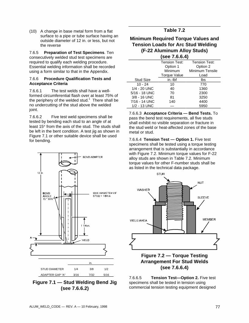
ALUM_WELD_CODE — REV. A — 10 February, 1998 77
(10) A change in base metal form from a flatsurface to a pipe or tube surface having anoutside diameter of 12 in. or less, but notthe reverse
7.6.5 Preparation of Test Specimens. Tenconsecutively welded stud test specimens arerequired to qualify each welding procedure.Essential welding information shall be recordedusing a form similar to that in the Appendix.
7.6.6 Procedure Qualification Tests andAcceptance Criteria
7.6.6.1 The test welds shall have a well-formed circumferential flash over at least 75% ofthe periphery of the welded stud.1 There shall beno undercutting of the stud above the weldedjoint.
7.6.6.2 Five test weld specimens shall betested by bending each stud to an angle of atleast 15° from the axis of the stud. The studs shallbe left in the bent condition. A test jig as shown inFigure 7.1 or other suitable device shall be usedfor bending.
in.
STUD DIAMETER 1/4 3/8 1/2
ADAPTER GAP “A” 3/16 7/32 5/16
Figure 7.1 — Stud Welding Bend Jig(see 7.6.6.2)
Table 7.2
Minimum Required Torque Values andTension Loads for Arc Stud Welding
(F-22 Aluminum Alloy Studs)(see 7.6.6.4)Tension Test:
Option 1Tension Test:
Option 2Minimum
Torque ValueMinimum Tensile
LoadStud Size in.-lbf lbs10 - 24 10 770
1/4 - 20 UNC 40 13605/16 - 18 UNC 70 23003/8 - 16 UNC 81 3250
7/16 - 14 UNC 140 44001/2 - 13 UNC — 5950
7.6.6.3 Acceptance Criteria — Bend Tests. Topass the bend test requirements, all five studsshall exhibit no visible separation or fracture inthe stud weld or heat-affected zones of the basemetal or stud.
7.6.6.4 Tension Test — Option 1. Five testspecimens shall be tested using a torque testingarrangement that is substantially in accordancewith Figure 7.2. Minimum torque values for F-22alloy studs are shown in Table 7.2. Minimumtorque values for other F-number studs shall beas listed in the technical data package.
Figure 7.2 — Torque TestingArrangement For Stud Welds
(see 7.6.6.4)
7.6.6.5 Tension Test—Option 2. Five testspecimens shall be tested in tension usingcommercial tension testing equipment designed
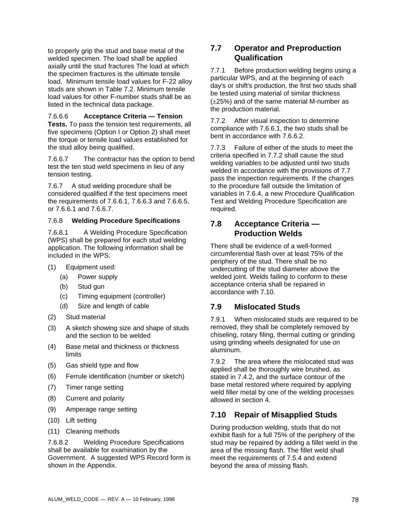
ALUM_WELD_CODE — REV. A — 10 February, 1998 78
to properly grip the stud and base metal of thewelded specimen. The load shall be appliedaxially until the stud fractures The load at whichthe specimen fractures is the ultimate tensileload. Minimum tensile load values for F-22 alloystuds are shown in Table 7.2. Minimum tensileload values for other F-number studs shall be aslisted in the technical data package.
7.6.6.6 Acceptance Criteria — TensionTests. To pass the tension test requirements, allfive specimens (Option I or Option 2) shall meetthe torque or tensile load values established forthe stud alloy being qualified.
7.6.6.7 The contractor has the option to bendtest the ten stud weld specimens in lieu of anytension testing.
7.6.7 A stud welding procedure shall beconsidered qualified if the test specimens meetthe requirements of 7.6.6.1, 7.6.6.3 and 7.6.6.5,or 7.6.6.1 and 7.6.6.7.
7.6.8 Welding Procedure Specifications
7.6.8.1 A Welding Procedure Specification(WPS) shall be prepared for each stud weldingapplication. The following information shall beincluded in the WPS:
(1) Equipment used:
(a) Power supply
(b) Stud gun
(c) Timing equipment (controller)
(d) Size and length of cable
(2) Stud material
(3) A sketch showing size and shape of studsand the section to be welded
(4) Base metal and thickness or thicknesslimits
(5) Gas shield type and flow
(6) Ferrule identification (number or sketch)
(7) Timer range setting
(8) Current and polarity
(9) Amperage range setting
(10) Lift setting
(11) Cleaning methods
7.6.8.2 Welding Procedure Specificationsshall be available for examination by theGovernment. A suggested WPS Record form isshown in the Appendix.
7.7 Operator and PreproductionQualification
7.7.1 Before production welding begins using aparticular WPS, and at the beginning of eachday's or shift's production, the first two studs shallbe tested using material of similar thickness(±25%) and of the same material M-number asthe production material.
7.7.2 After visual inspection to determinecompliance with 7.6.6.1, the two studs shall bebent in accordance with 7.6.6.2.
7.7.3 Failure of either of the studs to meet thecriteria specified in 7.7.2 shall cause the studwelding variables to be adjusted until two studswelded in accordance with the provisions of 7.7pass the inspection requirements. If the changesto the procedure fall outside the limitation ofvariables in 7.6.4, a new Procedure QualificationTest and Welding Procedure Specification arerequired.
7.8 Acceptance Criteria —Production Welds
There shall be evidence of a well-formedcircumferential flash over at least 75% of theperiphery of the stud. There shall be noundercutting of the stud diameter above thewelded joint. Welds failing to conform to theseacceptance criteria shall be repaired inaccordance with 7.10.
7.9 Mislocated Studs
7.9.1 When mislocated studs are required to beremoved, they shall be completely removed bychiseling, rotary filing, thermal cutting or grindingusing grinding wheels designated for use onaluminum.
7.9.2 The area where the mislocated stud wasapplied shall be thoroughly wire brushed, asstated in 7.4.2, and the surface contour of thebase metal restored where required by applyingweld filler metal by one of the welding processesallowed in section 4.
7.10 Repair of Misapplied Studs
During production welding, studs that do notexhibit flash for a full 75% of the periphery of thestud may be repaired by adding a fillet weld in thearea of the missing flash. The fillet weld shallmeet the requirements of 7.5.4 and extendbeyond the area of missing flash.

ALUM_WELD_CODE — REV. A — 10 February, 1998 79
Studs not meeting the Code requirements of 7.8other than deficient flash shall be removed andreplaced in accordance with 7.9.
Part C
Capacitor Discharge Stud Welding
7.11 General Requirements7.11.1 Nonflanged studs shall be limited to amaximum base diameter of ¼ in., and flangedstud base diameters shall be limited to amaximum of 5/16 in., unless permitted by thetechnical data package.
7.11.2 For contact, gap, and drawn arc capacitordischarge stud welding, the size and shape of thestud tip or projection, or the weld-end geometryshall be designed to achieve sound welds. Thesecharacteristics and the shank shape orconfiguration shall be as specified in thedrawings, specifications, or special provisions.
7.11.3 No ferrule is required.
7.11.4 Shielding gas is not required with thecontact or gap capacitor discharge process. Asuitable shielding gas shall be used with thedrawn arc capacitor discharge process.
7.11.5 The minimum base metal thickness forcapacitor discharge stud welding shall be no lessthan 25% of the base diameter of the stud.
7.12 Material Requirements7.12.1 Studs shall be made from cold drawn orextruded stock of alloys shown below. Otheralloys may be used when specified in thetechnical data package.
Aluminum Alloys ForCapacitor Discharge Stud Welding Applications
1100 55564043 60615183 60635356
7.12.2 Studs shall not be anodized, painted. orcoated with any foreign substance.
7.12.3 The contractor or manufacturer shallhave a method of verification (purchase order,packing slip, etc.) that provides evidence thatstuds conform to 7.12.
7.12.4 Mechanical testing of aluminum studalloys shall be in accordance with the applicable
sections of ASTM B557, Standard Methods ofTension Testing Wrought and Cast Aluminum andAluminum-Alloy and Magnesium-Alloy Products,or ANSI/AWS B4.0, Standard Methods forMechanical Testing of Welds.
7.12.5 Stud bases for capacitor dischargewelding studs may be flanged or nonflanged.
7.13 Workmanship7.13.1 Studs shall be free from oil, moisture,excessive oxide, or other deleterious matter thatwould adversely affect the welding operation.
7.13.2 Base metal to which studs are to bewelded shall be free of anodic coatings, moisture,or other injurious material to assure obtainingsound welds. These areas shall be cleaned byeither etching, brushing with a stainless steelbristle brush, scraping, or grinding.
7.13.3 Welded studs shall meet the visualinspection requirements of 7.17.
7.14 Technique7.14.1 Studs shall be welded with equipmentthat ensures the capacitors are fully charged to apreset value before the stud can be welded.
7.14.2 When required, welding grade shieldinggas (argon, helium, or helium/argon mixtures)shall be used.
7.14.3 A wetting agent may be introduced in theweld area just prior to the weld being made.
7.15 Qualification Requirements7.15.1 General. Prior to shop or fieldapplication, stud welding procedures shall beprepared and qualified according to therequirements of 7.15. The results of these testsshall be recorded on a stud procedurequalification record (PQR).
7.15.2 Responsibility for Tests. The contractorshall be responsible for the preparation andqualification of stud welding procedures. TheGovernment should accept properly documentedevidence of previous qualification of the studwelding procedures to be employed.
7.15.3 Welding Procedure Qualification
7.15.3.1 Preparation of Stud WeldingProcedures. Stud welding procedures shall beestablished in accordance with 7.15.4, except thata procedure established for each of twothicknesses of base metal using the same
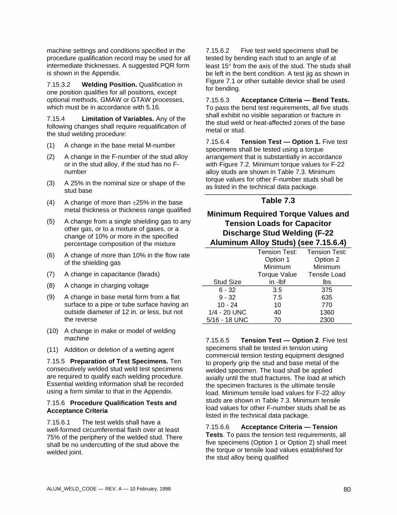
ALUM_WELD_CODE — REV. A — 10 February, 1998 80
machine settings and conditions specified in theprocedure qualification record may be used for allintermediate thicknesses. A suggested PQR formis shown in the Appendix.
7.15.3.2 Welding Position. Qualification inone position qualifies for all positions, exceptoptional methods, GMAW or GTAW processes,which must be in accordance with 5.16.
7.15.4 Limitation of Variables. Any of thefollowing changes shall require requalification ofthe stud welding procedure:
(1) A change in the base metal M-number
(2) A change in the F-number of the stud alloyor in the stud alloy, if the stud has no F-number
(3) A 25% in the nominal size or shape of thestud base
(4) A change of more than ±25% in the basemetal thickness or thickness range qualified
(5) A change from a single shielding gas to anyother gas, or to a mixture of gases, or achange of 10% or more in the specifiedpercentage composition of the mixture
(6) A change of more than 10% in the flow rateof the shielding gas
(7) A change in capacitance (farads)
(8) A change in charging voltage
(9) A change in base metal form from a flatsurface to a pipe or tube surface having anoutside diameter of 12 in. or less, but notthe reverse
(10) A change in make or model of weldingmachine
(11) Addition or deletion of a wetting agent
7.15.5 Preparation of Test Specimens. Tenconsecutively welded stud weld test specimensare required to qualify each welding procedure.Essential welding information shall be recordedusing a form similar to that in the Appendix.
7.15.6 Procedure Qualification Tests andAcceptance Criteria
7.15.6.1 The test welds shall have awell-formed circumferential flash over at least75% of the periphery of the welded stud. Thereshall be no undercutting of the stud above thewelded joint.
7.15.6.2 Five test weld specimens shall betested by bending each stud to an angle of atleast 15° from the axis of the stud. The studs shallbe left in the bent condition. A test jig as shown inFigure 7.1 or other suitable device shall be usedfor bending.
7.15.6.3 Acceptance Criteria — Bend Tests.To pass the bend test requirements, all five studsshall exhibit no visible separation or fracture inthe stud weld or heat-affected zones of the basemetal or stud.
7.15.6.4 Tension Test — Option 1. Five testspecimens shall be tested using a torquearrangement that is substantially in accordancewith Figure 7.2. Minimum torque values for F-22alloy studs are shown in Table 7.3. Minimumtorque values for other F-number studs shall beas listed in the technical data package.
Table 7.3
Minimum Required Torque Values andTension Loads for Capacitor
Discharge Stud Welding (F-22Aluminum Alloy Studs) (see 7.15.6.4)
Tension Test:Option 1
Tension Test:Option 2
MinimumTorque Value
MinimumTensile Load
Stud Size in.-lbf lbs6 - 32 3.5 3759 - 32 7.5 63510 - 24 10 770
1/4 - 20 UNC 40 13605/16 - 18 UNC 70 2300
7.15.6.5 Tension Test — Option 2. Five testspecimens shall be tested in tension usingcommercial tension testing equipment designedto properly grip the stud and base metal of thewelded specimen. The load shall be appliedaxially until the stud fractures. The load at whichthe specimen fractures is the ultimate tensileload. Minimum tensile load values for F-22 alloystuds are shown in Table 7.3. Minimum tensileload values for other F-number studs shall be aslisted in the technical data package.
7.15.6.6 Acceptance Criteria — TensionTests. To pass the tension test requirements, allfive specimens (Option 1 or Option 2) shall meetthe torque or tensile load values established forthe stud alloy being qualified
ALUM_WELD_CODE — REV. A — 10 February, 1998 81
7.15.6.7 The contractor has the option to bendtest the ten stud weld specimens in lieu of anytension testing.
7.15.7 A stud welding procedure shall beconsidered qualified if the test specimens meetthe requirements of 7.15.6.1, 7.15.6.3, and7.15.6.6, or 7.15.6.1 and 7.15.6.7.
7.15.8 Welding Procedure Specifications
7.15.8.1 A Welding Procedure Specification(WPS) shall be prepared for each stud weldingapplication. The following information shall beincluded in the welding procedure:
(1) Equipment used:
(a) Power control
(b) Stud gun
(c) Size and length of cable
(2) Stud material
(3) A sketch showing size and shape of studsand the section to be welded
(4) Base metal and thickness or thicknesslimits
(5) Gas shield type and flow (if applicable)
(6) Capacitance and charging voltage
(7) Drop height
(8) Capacitor discharge method
(9) Cleaning method
7.15.8.2 Welding Procedure Specificationsshall be available for examination by theGovernment. A suggested WPS form is shown inAppendix A.
7.16 Operator and PreproductionQualification
7.16.1 Before production welding begins using aparticular WPS, and at the beginning of eachday's or shift's production, the first two studs shallbe tested using material of similar thickness(±25%) and of the same material M-number asthe production material.
7.16.2 After visual inspection to determinecompliance with 7.15.6.1, the two studs shall bebent in accordance with 7.15.6.2.
7.16.3 Failure of either of the studs to meet thecriteria specified in 7.16.2 shall cause the studwelding variable parameters to be adjusted untiltwo studs welded in accordance with theprovisions of 7.16 pass the inspectionrequirements. If the changes to the procedure falloutside the limitation of variables in 7.15.4, a newProcedure Qualification Test and WeldingProcedure Specification are required.
7.17 Acceptance Criteria —Production Welds
There shall be evidence of a well-formedcircumferential flash over at least 75% of theperiphery of the stud. There shall be noundercutting of the stud diameter above thewelded joint. Welds failing to conform to theseacceptance criteria shall be repaired inaccordance with 7.19.
7.18 Mislocated Studs
7.18.1 When mislocated studs are required to beremoved, they shall be completely removed bychiseling, rotary filing, thermal cutting or grindingusing grinding wheels designated for use onaluminum.
7.18.2 The area where the mislocated stud wasapplied shall be thoroughly wire brushed, asstated in 7.13.2, and the surface contour of thebase metal restored where required by applyingweld filler metal by one of the welding processesallowed in section 4, Technique.
7.19 Repair of Misapplied Studs
During production welding, studs that do notexhibit flash for a full 75% of the periphery of thestud may be repaired by adding a fillet weld in thearea of the missing flash. The fillet weld shallmeet the requirements of 7.5.4 and extendbeyond the area of missing flash. Studs notmeeting the Code requirements of 7.17 other thandeficient flash shall be removed and replaced inaccordance with 7.18.
Footnotes
1. The expelled metal around the base of the stud isdesignated as flash in accordance with the definition ofupset in ANSI/AWS A3.0, Standard Welding Terms andDefinitions.

ALUM_WELD_CODE — REV. A — 10 February, 1998 82
ALUM_WELD_CODE — REV. A — 10 February, 1998 83
8. Non-Critical Welding
Part A
General Requirements
8.1 Application
8.1.1 Application to Existing Drawings
8.1.1.1 For all existing engineering drawings,the current nomenclature, “MIL-STD-372, ClassB” shall be equivalent to this requirement.
8.1.1.2 If a standard or specification on page116 is listed as a cross reference to section 8, butthe welds comply with the followingrequirements, section 8 of this Code shall apply.
(1) For all welds the following characteristicsmust be met:
(a) The weld must be a fillet weld, and shall beno larger than 5/16 inch.
(b) The weld shall not be longer than 18continuous inches.
(2) For all welds within the vehicle, the itemsupported by the bracket, hanger, clip,footman loop, etc., welded under thislimitation shall not exceed 35 pounds.
(3) For all welds on the exterior of the vehicle,the item supported by the bracket, hanger,clip, footman loop, etc., welded under thislimitation shall not exceed 50 pounds.
8.1.1.3 Any deviation from the aboverequirements may be accomplished using theform in Appendix A.
8.1.2 Application to New Drawings
8.1.2.1 This class of weld is applicable to allweld joints whose failure would not result in injuryto personnel, or in unfulfillment of an assignedmission. This class of welds is not applicable toballistic joints.
8.1.2.2 In all drawings subsequent to thiscode, the weld shall be noted on the technicaldata package as follows: “Weld in accordancewith UDLP/TACOM Ground Combat VehicleWelding Code -- Aluminum, Section 8.”
8.2 Base Metal
(1) ASTM B26, Standard Specification forAluminum Alloy Sand Castings
(2) ASTM B108, Standard Specification forAluminum Alloy Permanent-Mold Castings
(3) ASTM B209, Standard Specification forAluminum Alloy Sheet and Plate
(4) ASTM B210, Standard Specification forAluminum Alloy Drawn Seamless Tubes
(5) ASTM B211, Standard Specification forAluminum Alloy Bar, Rod, and Wire
(6) ASTM B221, Standard Specification forAluminum Alloy Extruded Bar, Rod, Wire,Shapes, and Tubes
(7) ASTM B241, Standard Specification forAluminum and Aluminum Alloy SeamlessPipe and Seamless Extruded Tube
(8) ASTM B247, Standard Specification forAluminum Alloy Die and Hand Forgings
(9) ASTM B308, Standard Specification forAluminum Alloy Standard StructuralShapes, Rolled or Extruded
(10) ASTM B313, Standard Specification forAluminum and Aluminum Alloy RoundWelded Tubes
(11) ASTM B361, Standard Specification forFactory Made Wrought Aluminum andAluminum-Alloy Welding Fittings
(12) ASTM B429 Standard Specification forAluminum-Alloy Extruded Structural Pipeand Tube
(13) ASTM B483, Standard Specification forAluminum-Alloy Drawn Tubes for GeneralPurpose Applications
(14) MIL-A-45225, Aluminum Alloy Armor,Forged
(15) MIL-A-46027, Aluminum Alloy Armor Plate,Weldable 5083 and 5456
(16) MIL-A-46063, Armor Plate, Aluminum Alloy,7039
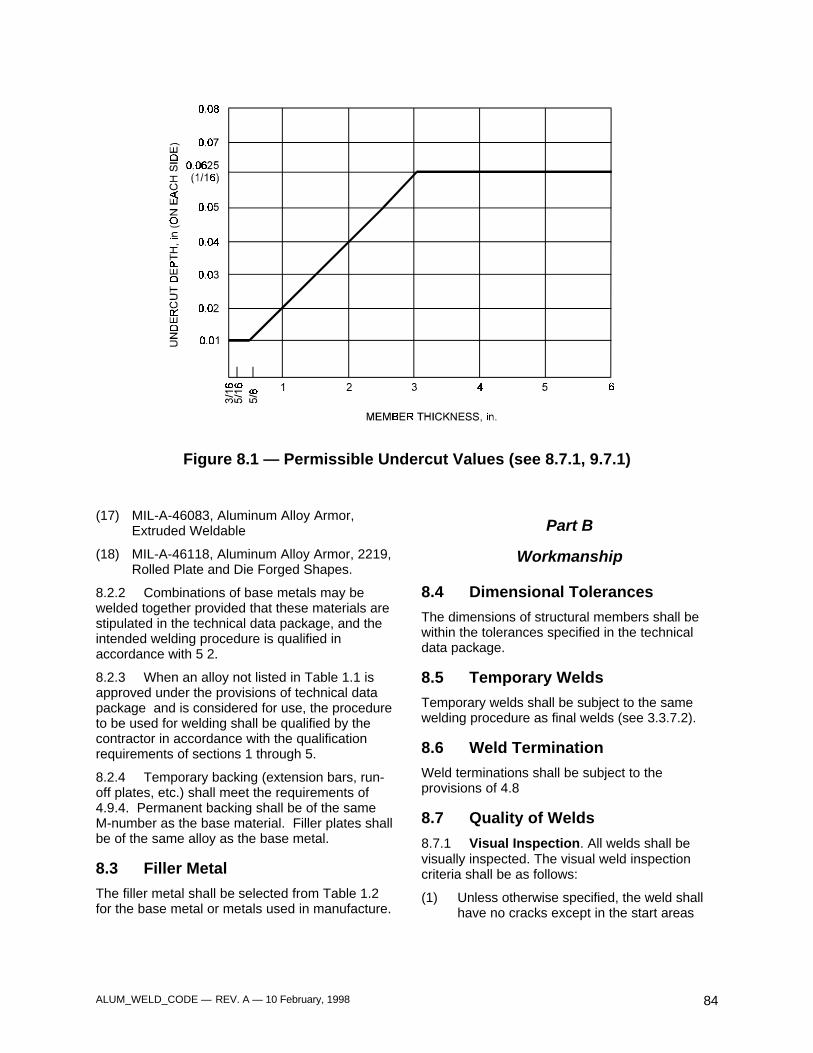
ALUM_WELD_CODE — REV. A — 10 February, 1998 84
Figure 8.1 — Permissible Undercut Values (see 8.7.1, 9.7.1)
(17) MIL-A-46083, Aluminum Alloy Armor,Extruded Weldable
(18) MIL-A-46118, Aluminum Alloy Armor, 2219,Rolled Plate and Die Forged Shapes.
8.2.2 Combinations of base metals may bewelded together provided that these materials arestipulated in the technical data package, and theintended welding procedure is qualified inaccordance with 5 2.
8.2.3 When an alloy not listed in Table 1.1 isapproved under the provisions of technical datapackage and is considered for use, the procedureto be used for welding shall be qualified by thecontractor in accordance with the qualificationrequirements of sections 1 through 5.
8.2.4 Temporary backing (extension bars, run-off plates, etc.) shall meet the requirements of4.9.4. Permanent backing shall be of the sameM-number as the base material. Filler plates shallbe of the same alloy as the base metal.
8.3 Filler Metal
The filler metal shall be selected from Table 1.2for the base metal or metals used in manufacture.
Part B
Workmanship
8.4 Dimensional Tolerances
The dimensions of structural members shall bewithin the tolerances specified in the technicaldata package.
8.5 Temporary Welds
Temporary welds shall be subject to the samewelding procedure as final welds (see 3.3.7.2).
8.6 Weld Termination
Weld terminations shall be subject to theprovisions of 4.8
8.7 Quality of Welds
8.7.1 Visual Inspection. All welds shall bevisually inspected. The visual weld inspectioncriteria shall be as follows:
(1) Unless otherwise specified, the weld shallhave no cracks except in the start areas
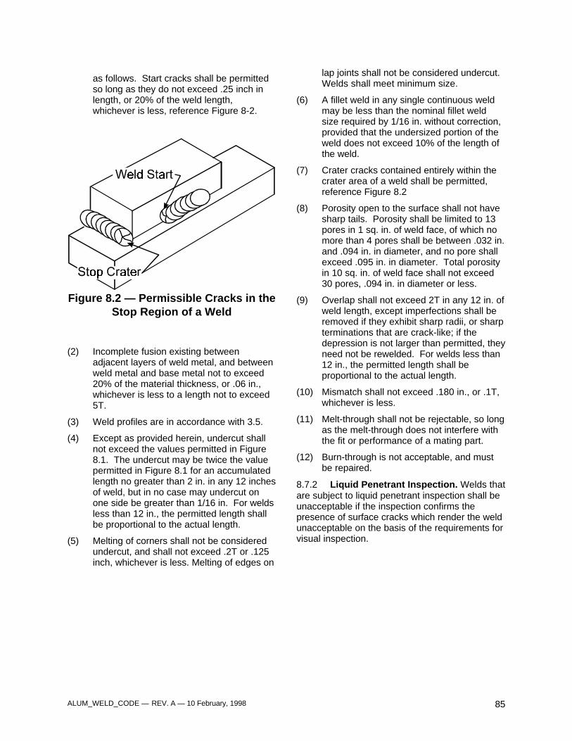
ALUM_WELD_CODE — REV. A — 10 February, 1998 85
as follows. Start cracks shall be permittedso long as they do not exceed .25 inch inlength, or 20% of the weld length,whichever is less, reference Figure 8-2.
Figure 8.2 — Permissible Cracks in theStop Region of a Weld
(2) Incomplete fusion existing betweenadjacent layers of weld metal, and betweenweld metal and base metal not to exceed20% of the material thickness, or .06 in.,whichever is less to a length not to exceed5T.
(3) Weld profiles are in accordance with 3.5.
(4) Except as provided herein, undercut shallnot exceed the values permitted in Figure8.1. The undercut may be twice the valuepermitted in Figure 8.1 for an accumulatedlength no greater than 2 in. in any 12 inchesof weld, but in no case may undercut onone side be greater than 1/16 in. For weldsless than 12 in., the permitted length shallbe proportional to the actual length.
(5) Melting of corners shall not be consideredundercut, and shall not exceed .2T or .125inch, whichever is less. Melting of edges on
lap joints shall not be considered undercut.Welds shall meet minimum size.
(6) A fillet weld in any single continuous weldmay be less than the nominal fillet weldsize required by 1/16 in. without correction,provided that the undersized portion of theweld does not exceed 10% of the length ofthe weld.
(7) Crater cracks contained entirely within thecrater area of a weld shall be permitted,reference Figure 8.2
(8) Porosity open to the surface shall not havesharp tails. Porosity shall be limited to 13pores in 1 sq. in. of weld face, of which nomore than 4 pores shall be between .032 in.and .094 in. in diameter, and no pore shallexceed .095 in. in diameter. Total porosityin 10 sq. in. of weld face shall not exceed30 pores, .094 in. in diameter or less.
(9) Overlap shall not exceed 2T in any 12 in. ofweld length, except imperfections shall beremoved if they exhibit sharp radii, or sharpterminations that are crack-like; if thedepression is not larger than permitted, theyneed not be rewelded. For welds less than12 in., the permitted length shall beproportional to the actual length.
(10) Mismatch shall not exceed .180 in., or .1T,whichever is less.
(11) Melt-through shall not be rejectable, so longas the melt-through does not interfere withthe fit or performance of a mating part.
(12) Burn-through is not acceptable, and mustbe repaired.
8.7.2 Liquid Penetrant Inspection. Welds thatare subject to liquid penetrant inspection shall beunacceptable if the inspection confirms thepresence of surface cracks which render the weldunacceptable on the basis of the requirements forvisual inspection.

ALUM_WELD_CODE — REV. A — 10 February, 1998 86
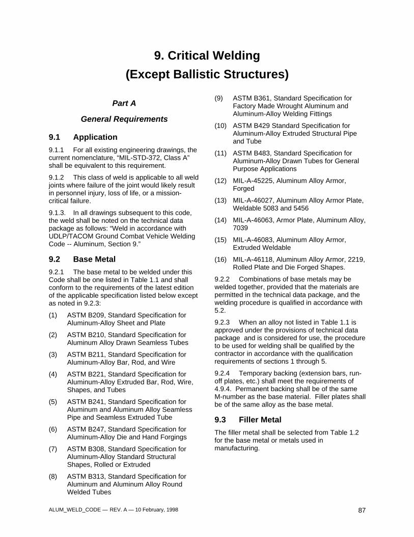
ALUM_WELD_CODE — REV. A — 10 February, 1998 87
9. Critical Welding
(Except Ballistic Structures)
Part A
General Requirements
9.1 Application
9.1.1 For all existing engineering drawings, thecurrent nomenclature, “MIL-STD-372, Class A”shall be equivalent to this requirement.
9.1.2 This class of weld is applicable to all weldjoints where failure of the joint would likely resultin personnel injury, loss of life, or a mission-critical failure.
9.1.3. In all drawings subsequent to this code,the weld shall be noted on the technical datapackage as follows: “Weld in accordance withUDLP/TACOM Ground Combat Vehicle WeldingCode -- Aluminum, Section 9.”
9.2 Base Metal
9.2.1 The base metal to be welded under thisCode shall be one listed in Table 1.1 and shallconform to the requirements of the latest editionof the applicable specification listed below exceptas noted in 9.2.3:
(1) ASTM B209, Standard Specification forAluminum-Alloy Sheet and Plate
(2) ASTM B210, Standard Specification forAluminum Alloy Drawn Seamless Tubes
(3) ASTM B211, Standard Specification forAluminum-Alloy Bar, Rod, and Wire
(4) ASTM B221, Standard Specification forAluminum-Alloy Extruded Bar, Rod, Wire,Shapes, and Tubes
(5) ASTM B241, Standard Specification forAluminum and Aluminum Alloy SeamlessPipe and Seamless Extruded Tube
(6) ASTM B247, Standard Specification forAluminum-Alloy Die and Hand Forgings
(7) ASTM B308, Standard Specification forAluminum-Alloy Standard StructuralShapes, Rolled or Extruded
(8) ASTM B313, Standard Specification forAluminum and Aluminum Alloy RoundWelded Tubes
(9) ASTM B361, Standard Specification forFactory Made Wrought Aluminum andAluminum-Alloy Welding Fittings
(10) ASTM B429 Standard Specification forAluminum-Alloy Extruded Structural Pipeand Tube
(11) ASTM B483, Standard Specification forAluminum-Alloy Drawn Tubes for GeneralPurpose Applications
(12) MIL-A-45225, Aluminum Alloy Armor,Forged
(13) MIL-A-46027, Aluminum Alloy Armor Plate,Weldable 5083 and 5456
(14) MIL-A-46063, Armor Plate, Aluminum Alloy,7039
(15) MIL-A-46083, Aluminum Alloy Armor,Extruded Weldable
(16) MIL-A-46118, Aluminum Alloy Armor, 2219,Rolled Plate and Die Forged Shapes.
9.2.2 Combinations of base metals may bewelded together, provided that the materials arepermitted in the technical data package, and thewelding procedure is qualified in accordance with5.2.
9.2.3 When an alloy not listed in Table 1.1 isapproved under the provisions of technical datapackage and is considered for use, the procedureto be used for welding shall be qualified by thecontractor in accordance with the qualificationrequirements of sections 1 through 5.
9.2.4 Temporary backing (extension bars, run-off plates, etc.) shall meet the requirements of4.9.4. Permanent backing shall be of the sameM-number as the base material. Filler plates shallbe of the same alloy as the base metal.
9.3 Filler Metal
The filler metal shall be selected from Table 1.2for the base metal or metals used inmanufacturing.
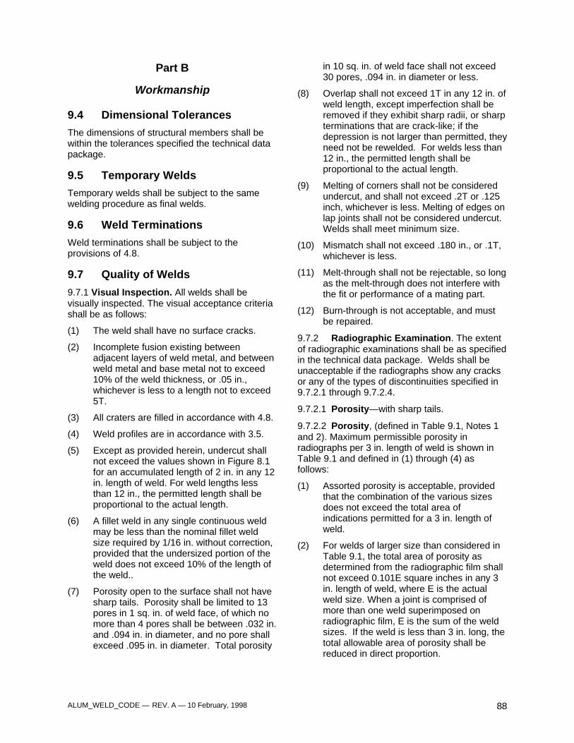
ALUM_WELD_CODE — REV. A — 10 February, 1998 88
Part B
Workmanship
9.4 Dimensional Tolerances
The dimensions of structural members shall bewithin the tolerances specified the technical datapackage.
9.5 Temporary Welds
Temporary welds shall be subject to the samewelding procedure as final welds.
9.6 Weld Terminations
Weld terminations shall be subject to theprovisions of 4.8.
9.7 Quality of Welds
9.7.1 Visual Inspection. All welds shall bevisually inspected. The visual acceptance criteriashall be as follows:
(1) The weld shall have no surface cracks.
(2) Incomplete fusion existing betweenadjacent layers of weld metal, and betweenweld metal and base metal not to exceed10% of the weld thickness, or .05 in.,whichever is less to a length not to exceed5T.
(3) All craters are filled in accordance with 4.8.
(4) Weld profiles are in accordance with 3.5.
(5) Except as provided herein, undercut shallnot exceed the values shown in Figure 8.1for an accumulated length of 2 in. in any 12in. length of weld. For weld lengths lessthan 12 in., the permitted length shall beproportional to the actual length.
(6) A fillet weld in any single continuous weldmay be less than the nominal fillet weldsize required by 1/16 in. without correction,provided that the undersized portion of theweld does not exceed 10% of the length ofthe weld..
(7) Porosity open to the surface shall not havesharp tails. Porosity shall be limited to 13pores in 1 sq. in. of weld face, of which nomore than 4 pores shall be between .032 in.and .094 in. in diameter, and no pore shallexceed .095 in. in diameter. Total porosity
in 10 sq. in. of weld face shall not exceed30 pores, .094 in. in diameter or less.
(8) Overlap shall not exceed 1T in any 12 in. ofweld length, except imperfection shall beremoved if they exhibit sharp radii, or sharpterminations that are crack-like; if thedepression is not larger than permitted, theyneed not be rewelded. For welds less than12 in., the permitted length shall beproportional to the actual length.
(9) Melting of corners shall not be consideredundercut, and shall not exceed .2T or .125inch, whichever is less. Melting of edges onlap joints shall not be considered undercut.Welds shall meet minimum size.
(10) Mismatch shall not exceed .180 in., or .1T,whichever is less.
(11) Melt-through shall not be rejectable, so longas the melt-through does not interfere withthe fit or performance of a mating part.
(12) Burn-through is not acceptable, and mustbe repaired.
9.7.2 Radiographic Examination. The extentof radiographic examinations shall be as specifiedin the technical data package. Welds shall beunacceptable if the radiographs show any cracksor any of the types of discontinuities specified in9.7.2.1 through 9.7.2.4.
9.7.2.1 Porosity—with sharp tails.
9.7.2.2 Porosity, (defined in Table 9.1, Notes 1and 2). Maximum permissible porosity inradiographs per 3 in. length of weld is shown inTable 9.1 and defined in (1) through (4) asfollows:
(1) Assorted porosity is acceptable, providedthat the combination of the various sizesdoes not exceed the total area ofindications permitted for a 3 in. length ofweld.
(2) For welds of larger size than considered inTable 9.1, the total area of porosity asdetermined from the radiographic film shallnot exceed 0.101E square inches in any 3in. length of weld, where E is the actualweld size. When a joint is comprised ofmore than one weld superimposed onradiographic film, E is the sum of the weldsizes. If the weld is less than 3 in. long, thetotal allowable area of porosity shall bereduced in direct proportion.
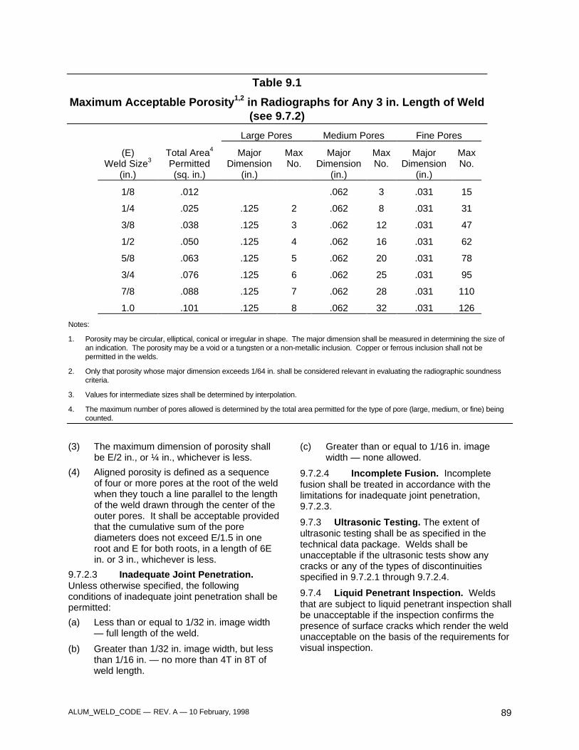
ALUM_WELD_CODE — REV. A — 10 February, 1998 89
Table 9.1
Maximum Acceptable Porosity1,2 in Radiographs for Any 3 in. Length of Weld(see 9.7.2)
Large Pores Medium Pores Fine Pores
(E)Weld Size3
(in.)
Total Area4
Permitted(sq. in.)
MajorDimension
(in.)
MaxNo.
MajorDimension
(in.)
MaxNo.
MajorDimension
(in.)
MaxNo.
1/8 .012 .062 3 .031 15
1/4 .025 .125 2 .062 8 .031 31
3/8 .038 .125 3 .062 12 .031 47
1/2 .050 .125 4 .062 16 .031 62
5/8 .063 .125 5 .062 20 .031 78
3/4 .076 .125 6 .062 25 .031 95
7/8 .088 .125 7 .062 28 .031 110
1.0 .101 .125 8 .062 32 .031 126
Notes:
1. Porosity may be circular, elliptical, conical or irregular in shape. The major dimension shall be measured in determining the size ofan indication. The porosity may be a void or a tungsten or a non-metallic inclusion. Copper or ferrous inclusion shall not bepermitted in the welds.
2. Only that porosity whose major dimension exceeds 1/64 in. shall be considered relevant in evaluating the radiographic soundnesscriteria.
3. Values for intermediate sizes shall be determined by interpolation.
4. The maximum number of pores allowed is determined by the total area permitted for the type of pore (large, medium, or fine) beingcounted.
(3) The maximum dimension of porosity shallbe E/2 in., or ¼ in., whichever is less.
(4) Aligned porosity is defined as a sequenceof four or more pores at the root of the weldwhen they touch a line parallel to the lengthof the weld drawn through the center of theouter pores. It shall be acceptable providedthat the cumulative sum of the porediameters does not exceed E/1.5 in oneroot and E for both roots, in a length of 6Ein. or 3 in., whichever is less.
9.7.2.3 Inadequate Joint Penetration.Unless otherwise specified, the followingconditions of inadequate joint penetration shall bepermitted:
(a) Less than or equal to 1/32 in. image width— full length of the weld.
(b) Greater than 1/32 in. image width, but lessthan 1/16 in. — no more than 4T in 8T ofweld length.
(c) Greater than or equal to 1/16 in. imagewidth — none allowed.
9.7.2.4 Incomplete Fusion. Incompletefusion shall be treated in accordance with thelimitations for inadequate joint penetration,9.7.2.3.
9.7.3 Ultrasonic Testing. The extent ofultrasonic testing shall be as specified in thetechnical data package. Welds shall beunacceptable if the ultrasonic tests show anycracks or any of the types of discontinuitiesspecified in 9.7.2.1 through 9.7.2.4.
9.7.4 Liquid Penetrant Inspection. Weldsthat are subject to liquid penetrant inspection shallbe unacceptable if the inspection confirms thepresence of surface cracks which render the weldunacceptable on the basis of the requirements forvisual inspection.

ALUM_WELD_CODE — REV. A — 10 February, 1998 90
ALUM_WELD_CODE — REV. A — 10 February, 1998 91
10. Ballistic Welding
Part A
General Requirements
10.1 Application
10.1.1 For all existing engineering drawings, thecurrent nomenclature, “MIL-STD-1946” shall beequivalent to this requirement.
10.1.2 This class of weld is applicable to weldjoints in a ballistic structure which are critical tothe ballistic integrity of the structure. Weld jointwhich are not critical to the ballistic integrity of aballistic structure may be specified with non-ballistic weld classes. Non-ballistic weld classes,as defined in Sections 8 and 9, may be specifiedon the same ballistic structure.
10.1.3 In all drawings subsequent to this code,the weld shall be noted on the technical datapackage as follows: “Weld in accordance withUDLP/TACOM Ground Combat Vehicle WeldingCode -- Aluminum, Section 10.”
10.2 Base Metal
10.2.1 The base metal to be welded under thisCode shall be limited to those listed below:
(1) MIL-A-45225, Aluminum Alloy Armor,Forged
(2) MIL-A-46027, Aluminum Alloy Armor Plate,Weldable 5083 and 5456
(3) MIL-A-46063, Armor Plate, Aluminum Alloy,7039
(4) MIL-A-46083, Aluminum Alloy Armor,Extruded Weldable
(5) MIL-A-46118, Aluminum Alloy Armor, 2219,Rolled Plate and Die Forged Shapes.
10.2.2 Combinations of base metals may bewelded together, provided welding procedure isqualified in accordance with 5.2, 10.6 and 10.9.
10.2.3 Temporary backing (extension bars, run-off plates, etc.) shall meet the requirements of4.9.4. Permanent backing shall be of the sameM-number as the base material. Filler plates shallbe of the same alloy as the base metal.
10.3 Filler Metal
The filler metal shall be selected from Table 1.2for the base metal or metals used in manufacture.
Part B
Workmanship
10.4 Temporary Welds
10.4.1 Temporary welds shall be subject to thesame welding procedure and quality requirementsas final welds.
10.5 Weld Terminations
Weld terminations shall be subject to theprovisions of 4.8.
10.6 Ballistic Certification
10.6.1 Ballistic Testing
10.6.1.1 Ballistic weld procedures that havebeen previously qualified shall be consideredacceptable by the Government for other ballisticweldments provided the limitations of 5.16 andthe joint type/design tolerances are maintained.
10.6.1.2 Ballistic testing will be carried out, inaccordance with the requirements of 10.9 at anyTECOM-approved test agency. The contractor ormanufacturer shall fabricate ballistic test samples(10.6.1.4) prior to beginning production.Certification shall be issued upon acceptableperformance of the material under ballistic shocktest (10.9).
10.6.1.3 Unless otherwise specified, when achange in any factor of the WPS outside thelimitations specified in 5.16, or as listed below, isdesired, a new PQR shall be submitted forapproval. Recertification shall be conducted inthe same manner as in the original certificationprocedure.
(a) A change is made from mechanical tothermal or a combination of mechanicaland thermal to thermal edge preparation.
(b) A change is made from a mechanical to athermal method of preparing the root ofjoint before welding the second side, but notvice versa.
10.6.1.4 Ballistic weld joints will becategorized by armor material types and jointdesign. Representative samples of each type maybe selected by the procuring activity inconsideration of material thickness and plateobliquity.
10.6.1.5 Ballistic test samples shall be weldedusing the contractor’s PQR for the joint
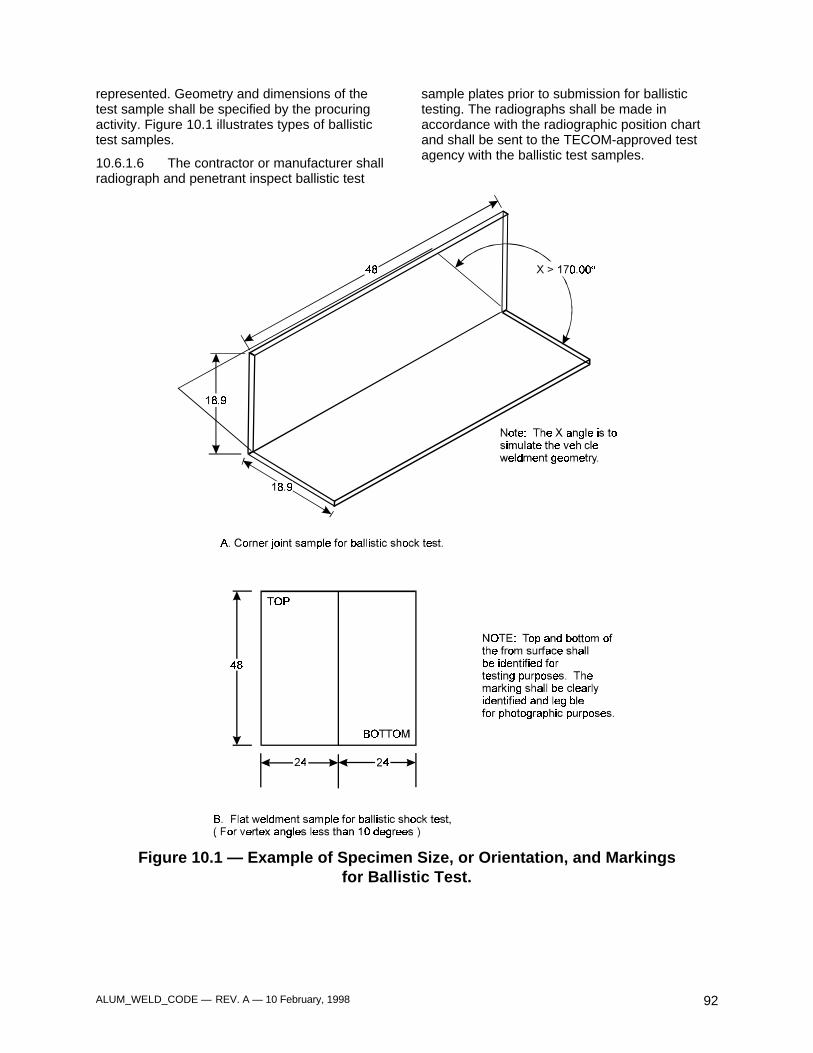
ALUM_WELD_CODE — REV. A — 10 February, 1998 92
represented. Geometry and dimensions of thetest sample shall be specified by the procuringactivity. Figure 10.1 illustrates types of ballistictest samples.
10.6.1.6 The contractor or manufacturer shallradiograph and penetrant inspect ballistic test
sample plates prior to submission for ballistictesting. The radiographs shall be made inaccordance with the radiographic position chartand shall be sent to the TECOM-approved testagency with the ballistic test samples.
Figure 10.1 — Example of Specimen Size, or Orientation, and Markingsfor Ballistic Test.
ALUM_WELD_CODE — REV. A — 10 February, 1998 93
10.6.2 Marking of Test Samples.
10.6.2.1 Original Submissions. Eachballistic test sample shall be marked for easyidentification. Marking shall be in letters, digits orboth, clearly legible and shall include thespecimen identification, submission date,contractor's name or trademark, and top andbottom, and front and back identification. Theinformation shall be marked on the specimen asspecified by the test director. The impact side ofeach sample shall be marked "IMPACT SIDE"with letters at least 25.4 mm (1 inch) high.
10.6.2.2 Retest Samples. Retest samplesshall be marked with the original test sampleidentification, and any additional identificationspecified. This will be followed by the letter "R" toindicate retest.
10.6.3 Submission of Data. Unlessotherwise specified, the WPS data and theradiographic inspection report, including elements(a) through (e) in the following listing shall besubmitted with each ballistic test sample:
(a) Ballistic plate number
(b) Manufacturers name and address
(c) Contract number
(d) Thickness of plates
(e) Plate specification number
10.6.4 Ballistic Testing
10.6.4.1 Preliminary Ballistic Testing. Theballistic test sample submitted to the test agencyfor ballistic shock testing may be subjected to aradiographic inspection (10.8.2) at the testingagency. On passing the radiographic inspectionrequirement it shall then be subjected to theballistic shock test in accordance with 10.9
10.6.4.2 Request for Retest. If a ballistictest sample fails to pass, the contractor ormanufacturer, upon notification can immediatelyrequest a retest. If no request is made within 10days after notification, the PQR and or jointdesign shall be rejected.
10.6.4.3 Retest Sample Submission. If thecontractor or manufacturer requests a retest, twoadditional test specimens shall be submitted tothe test agency for test. The samples shall bewelded by the established PQR used for theoriginal test specimen and marked in accordancewith 10.6.2.2. Failure of either sample in theretest shall be cause for rejection of the PQR.
10.7 Macro Specimens
10.7.1 Number and type of test specimens.One macro specimen shall be made for each typeof joint included in PQR. This specimen may becut from the ballistic test specimen (Figure 10.1)so long as the dimensions of Figure 10.1 are met.
10.8 Quality of Welds
10.8.1 Visual Inspection. All welds shall bevisually inspected. The visual weld inspectioncriteria shall be as follows:
(1) The weld shall have no surface cracks.
(2) Incomplete fusion exists between adjacentlayers of weld metal, and between weldmetal and base metal not to exceed 10% ofthe weld thickness, or .03 in., whichever isless to a length not to exceed 1T.
(3) All craters are filled in accordance with 4.8.
(4) Weld profiles are in accordance with 3.5.
(5) Except as provided herein, undercut shallnot exceed the values shown in Figure 8.1for an accumulated length of 2 in. in any 12in. length of weld. For weld lengths lessthan 12 in., the permitted length shall beproportional to the actual length.
(6) A fillet weld in any single continuous weldmay be less than the nominal fillet weldsize required by 1/16 in. without correction,provided that the undersized portion of theweld does not exceed 10% of the length ofthe weld.
(7) Porosity open to the surface shall not havesharp tails. Porosity shall be limited to 6pores in 1 sq. in. of weld face, of which nomore than 2 pores shall be between .032 in.and .094 in. in diameter, and no pore shallexceed .095 in. in diameter. Total porosityin 10 sq. in. of weld face shall not exceed15 pores, .094 in. in diameter or less.
(8) Overlap shall not exceed 1T in any 12 in. ofweld length, except imperfection shall beremoved if they exhibit sharp radii, or sharpterminations that are crack-like; if thedepression is not larger than permitted, theyneed not be rewelded. For welds less than12 in., the permitted length shall beproportional to the actual length.
(9) Melting of corners shall not be consideredundercut, and shall not exceed .2T or .125inch, whichever is less. Melting of edges on
ALUM_WELD_CODE — REV. A — 10 February, 1998 94
lap joints shall not be considered undercut.Welds shall meet minimum size.
(10) Mismatch shall not exceed .180 in., or .1T,whichever is less.
10.8.2 Radiographic Examination.
10.8.2.1 The extent of radiographicexaminations shall be as specified in the contractdocuments.
10.8.2.2 Radiographic Position Drawings.A radiographic position drawing and weldingassembly drawings shall be submitted to theprocurement activity for review and acceptance inestablishment of radiographic standards andRoutine Positions. This drawing contain thefollowing:
(a) An isometric or plan view or both of theweldment.
(b) Identification, by letter or number(s) of thejoint(s) to be radiographed as identified onthe assembly drawing.
(c) Identification of positions by letter ornumber.
(d) Cross-section of the joint(s) showing theidentification and type of the joint(s), bysymbol and the thickness of the matingpieces.
(e) A table entitled “Routine Positions”containing five columns entitled “Position,front”, “Position, rear”, “Position, left side”,“Position, right side”, and “Film size”.
(f) A table entitled “Random Positions”containing two columns entitled “Positions”and “Film size”.
(g) Notes, reading as follows:
(1) “Random shots” to be selected by thecontractor and approved by theGovernment.
(2) Unless otherwise specified, therequirements and discontinuity typesspecified in 9.7.2 shall serve as a basisfor the radiographic acceptancestandards to be prepared by theprocuring or design agency. However,the 1/32 inch lack of penetration at theapex of the weld joint described in9.7.2.3 (a) does not apply to highcurrent density joint geometry. Theradiographic acceptance standardsshall be indicated on the applicable
radiographic position chart, drawing orcontract requirement.
(3) Routine position shall be radiographedin such a way as to cover all the leftside joint types as specified on theradiographic position chart onalternating lots. The same procedurewill be followed for the right side. Onehundred percent joint type coverage willbe achieved over a span of 2 controlweldments.
(4) If the radiographs appear questionableas to acceptability, additionalradiographs shall be taken.
(5) The frequency of radiographicinspection shall be as shown in Table10.1, unless otherwise specified.
10.8.3 Inspection of Production Weldments.
10.8.3.1 First Production Weldment. Thefirst weldment in production shall be radiographedso as to attain 100% coverage of all joint typesindicated on the radiographic position drawing.Subsequent weldments will be radiographed inthose areas that were defective until complianceis met. This is accomplished through a phase outof rejections.
10.8.3.2 Spot Checking. After therequirements in 10.8.3.1 have been met, jointswill be spot checked by radiography inaccordance with 10.8.2.2 (g) (1) and (3). Usuallyonly one radiograph shall be required on anyspecific joint with a frequency as controlled byTable 10.1. Thus, spot checking will not usuallyrequire radiographing of all joints in a singleweldment. If an area is found rejectable whenspot checking, the remainder of the joint will beradiographed unless otherwise specified. Cracks½ in. or less at either end of a weld joint shall notrequire radiography of the remainder of the weldjoint.
10.8.3.3 Checking of Rejectable RandomPosition. When spot checking random positionsin accordance with 10.8.3.2 reveals rejectablediscontinuities, additional radiography may berequired as prescribed in accordance with Table10.2.
10.8.3.4 Checking of Rejectable RoutinePositions. When radiographs required in10.8.3.2 indicates an area or areas that do notconform to the radiographic standard, thecorresponding joint on the next available
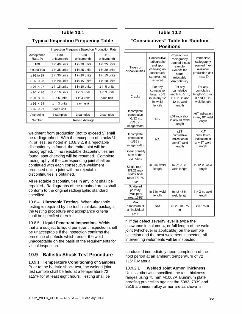
ALUM_WELD_CODE — REV. A — 10 February, 1998 95
Table 10.1
Typical Inspection Frequency Table
Inspection Frequency Based on Production Rate
AcceptanceRate, %
> 30units/month
15-30units/month
<15units/month
100 1 in 40 units 1 in 30 units 1 in 25 units
≥ 99 to 100 1 in 35 units 1 in 25 units 1 in 20 units
≥ 98 to 99 1 in 30 units 1 in 20 units 1 in 15 units
≥ 97 < 98 1 in 20 units 1 in 15 units 1 in 10 units
≥ 96 < 97 1 in 15 units 1 in 10 units 1 in 5 units
≥ 95 < 96 1 in 10 units 1 in 5 units 1 in 3 units
≥ 94 < 95 1 in 5 units 1 in 3 units each unit
≥ 93 < 94 1 in 3 units each unit
≥ 92 < 93 each unit
Averaging 5 samples 3 samples 2 samples
Number Rolling Average
weldment from production (not to exceed 5) shallbe radiographed. With the exception of cracks ½in. or less, as noted in 10.8.3.2, if a rejectablediscontinuity is found, the entire joint will beradiographed. If no rejectable discontinuities arefound, spot checking will be resumed. Completeradiography of the corresponding joint shall becontinued with each consecutive weldmentproduced until a joint with no rejectablediscontinuities is obtained.
All rejectable discontinuities in any joint shall berepaired. Radiographs of the repaired areas shallconform to the original radiographic standardspecified.
10.8.4 Ultrasonic Testing. When ultrasonictesting is required by the technical data package,the testing procedure and acceptance criteriashall be specified therein.
10.8.5 Liquid Penetrant Inspection. Weldsthat are subject to liquid penetrant inspection shallbe unacceptable if the inspection confirms thepresence of defects which render the weldunacceptable on the basis of the requirements forvisual inspection.
10.9 Ballistic Shock Test Procedure
10.9.1 Temperature Conditioning of Samples.Prior to the ballistic shock test, the welded jointtest sample shall be held at a temperature 72±15°F for at least eight hours. Testing shall be
Table 10.2
“Consecutives” Table for RandomPositions
Types ofdiscontinuities
Consecutiveradiography
and spotchecking onsubsequentsamples not
required
Consecutiveradiography
required if nextsample
exhibits thesame
rejectablediscontinuity
Immediateradiography
required (nextavailable
production unit– max 5)*
Cracks
For anycumulativelength ≤0.5in. in any 12
in. weldlength
For anycumulative
length >0.5 in.,≤1.0 in. in and
12 in. weldlength
For anycumulative
length >1.0 in.in and 12 in.weld length
Incompletepenetration>1/32 in.,≤1/16 in.
image width
NA≤6T indicationin any 8T weld
length
>6T indicationin any 8T weld
length
Incompletepenetration>1/16 in.
image width
NA
≤1Tcumulativeindication inany 8T weld
length
>1Tcumulativeindication inany 8T weld
length
Linear porositysum of thediameters
Single root –E/1.25 maxand/or bothroots E/0.75
max
In 3 in. weldlength
In ≥2 <3 in.weld length
In <2 in. weldlength
Scatteredporosity
(Max porearea .151E)
In 3 in. weldlength
In ≥2 <3 in.weld length
In <2 in. weldlength
Maxdimension ofan individual
pore
N/A >0.25 ≤0.375in
>0.375 in.
* If the defect severity level is twice theallowance in column 4, or full length of the weldjoint (whichever is applicable) on the sampleselection and the next weldment inspected, allintervening weldments will be inspected.
conducted immediately upon completion of thehold period at an ambient temperature of 72±15°F.Material
10.9.2.1 Welded Joint Armor Thickness.Unless otherwise specified, the test thicknessranges using 75 mm M1002A aluminum plateproofing projectiles against the 5083, 7039 and2519 aluminum alloy armor are as shown in
ALUM_WELD_CODE — REV. A — 10 February, 1998 96
Tables 10.3, 10.4 and 10.7. The test thicknessranges using the 57 mm M1001A aluminum plateproofing projectiles against the same alloys are asshown in Tables 10.5 and 10.6.
10.9.2.2 Test Sample ThicknessMeasurement. Unless otherwise specified, eachof the two components making up the welded jointshall be measured for thickness in at least fourlocations at least 1 in. from the edges. Thicknessshall be read to the nearest 0.001 in. using amicrometer. The average of the readings takenon each component shall be considered as thethickness of the plate, forging or extrusion.
10.9.3 Test Fixture. The ballistic test sampleshall be supported rigidly using wedges asnecessary in an appropriate test fixture selectedby the test director. A 30-in. distance betweensupports shall be sustained for flat weldments.
10.9.4 Test Obliquity. The line of fire shall beperpendicular to the sample surface at the impactlocation (zero degrees obliquity).
10.9.5 Fair Impact. A fair impact is one whichmeets the requirements of 10.9.4, 10.9.6, 10.9.7and 10.9.8.
10.9.6 Impact Location.
10.9.6.1 Corner Joint (Various Angles).Unless otherwise specified, the impact locationshall be measured from the backside of the plate(<170°). The center of the projectile impact shallbe within 2 ± ½ in. from the toe of the weld on thebackside. If the backside of the weld joint designdoes not have a weld, then the impact locationshall be measured from the intersection of the twoplates on the backside. The aiming point for thecenter of the first impact (10.9.8.1) shall be 13 ±1in. from the top of the target. The second impactshall be 13 ±1 in. from the bottom of the target, oras otherwise required by the test director.
10.9.6.2 Flat Weldments. Unless otherwisespecified, the impact location shall be no furtherthan ½ in. from the centerline of the weld andbetween 12 in., and 13 in. from the top of the testsample.
10.9.7 Striking Velocities.
10.9.7.1 Corner Joints. Striking velocitiesshall be chosen from Tables 10.3 through 10.7based on the alloy and thickness of the plate tobe impacted. Striking velocities on alloys notcovered by these tables shall be as agreed uponin the contract.
10.9.7.2 Flat weldments.
10.9.7.2.1 Weldment Made of Two Plates ofSame Material and Thickness. Strikingvelocities shall be chosen from Table 10.3 forimpacts on 5083 alloy armor, from Table 10.4 forimpacts on 7039 alloy armor and from Table 10.7for impacts on 2519 alloy armor. Striking velocityon other armor types shall be as agreed upon inthe contract.
10.9.7.2.2 Weldment Made of Two Plates ofDifferent Alloys But Same Thickness. Thestriking velocity shall be that which is required forthe weaker alloy.
10.9.7.2.3 Weldment Made of Two Plates ofDifferent Alloys and Thicknesses. The strikingvelocity shall be the lower of the two consideringthe alloy and thickness.
10.9.8 Number of impacts
10.9.8.1 Corner Joints. One fair impact isrequired on each of the two pieces making up thewelded joint. The thinner of the two plates orcomponents shall be impacted first. Should athird round be required, the procedure of 10.9.13shall be followed.
10.9.8.2 Flat weldments. One fair impact isrequired on the welded joint. Should a secondround be required, the procedure of 10.9.11.2shall be followed.
10.9.9 Photographic Record and Inspectionof Impact Area. Close up photographs of thefront and back of the impacted area showing anycracks present shall be taken after each impact.Front, back and length of cracking shall be clearlyidentified for photographic records. The impactedarea shall be inspected with liquid dye penetrantin accordance with MIL-STD-6866 whenevervisual crack length approaches the maximumpermitted.
10.9.10 Excessive Cracking on a First RoundFair Impact. Excessive cracking (10.9.14) shallbe cause for rejection of the PQR for that jointdesign.
10.9.11 Second Impacts.
10.9.11.1 Corner Joints. After a firstround fair impact without excessive cracking, thesecond impact shall be on the plate not previouslyimpacted and at the opposite end of the sample(section 10.9.6). Should excessive cracking occuron the second impact, it will be cause for rejectingthe weld procedure for that joint design.
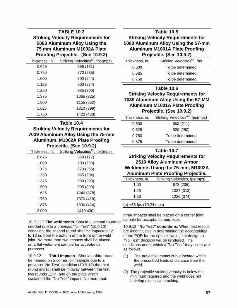
ALUM_WELD_CODE — REV. A — 10 February, 1998 97
TABLE 10.3Striking Velocity Requirements for
5083 Aluminum Alloy Using the75 mm Aluminum M1002A PlateProofing Projectile. (See 10.9.2)
Thickness, in. Striking Velocities(a), fps(mps)0.625 595 (181)
0.750 770 (235)
1.000 800 (244)
1.125 900 (274)
1.250 985 (300)
1.375 1065 (325)
1.500 1155 (352)
1.625 1310 (399)
1.750 1420 (433)
Table 10.4Striking Velocity Requirements for
7039 Aluminum Alloy Using the 75-mmAluminum, M1002A Plate Proofing
Projectile. (See 10.9.2)Thickness, in. Striking Velocities(a), fps(mps)
0.875 550 (177)
1.000 780 (238)
1.125 870 (265)
1.250 965 (294)
1.375 980 (299)
1.500 995 (303)
1.625 1240 (378)
1.750 1370 (418)
1.875 1390 (424)
2.000 1410 430)
10.9.11.2 Flat weldments. Should a second round beneeded due to a previous “No Test” (10.9.13)condition, the second round shall be impacted 12to 13 in. from the bottom of the front of the weldjoint. No more than two impacts shall be placedon a flat weldment sample for acceptancepurposes.
10.9.12 Third impacts Should a third roundbe needed on a corner joint sample due to aprevious “No Test” condition (10.9.13) the thirdround impact shall be midway between the firsttwo rounds ±2 in. and on the plate whichsustained the “No Test” impact. No more than
Table 10.5Striking Velocity Requirements for
5083 Aluminum Alloy Using the 57-mmAluminum M1001A Plate Proofing
Projectile. (See 10.9.2)Thickness, in. Striking Velocities(a), fps
0.500 To be determined
0.625 To be determined
0.750 To be determined
Table 10.6Striking Velocity Requirements for
7039 Aluminum Alloy Using the 57-MMAluminum M1001A Plate Proofing
Projectile. (See 10.9.2)Thickness, in. Striking Velocities(a), fps(mps)
0.500 693 (211)
0.625 920 (280)
0.750 To be determined
0.875 To be determined
Table 10.7Striking Velocity Requirements for
2519 Alloy Aluminum ArmorWeldments Using the 75-mm, M1002AAluminum Plate Proofing Projectile.
Thickness, in. Striking Velocities, fps(mps)1.00 673 (205)
1.25 1027 (313)
1.50 1226 (374)
(a) ±33 fps (10.24 mps)
three impacts shall be placed on a corner jointsample for acceptance purposes.
10.9.13 “No Test” conditions. When test resultsare inconclusive in determining the acceptabilityof the PQR for the specific weld joint design, a“No Test” decision will be rendered. Theconditions under which a "No Test" may occur areas follows:
(1) The projectile impact is not located withinthe prescribed limits of distance from theweld.
(2) The projectile striking velocity is below theminimum required and the weld does notdevelop excessive cracking.
ALUM_WELD_CODE — REV. A — 10 February, 1998 98
(3) The projectile striking velocity is above themaximum allowed and the weld developsexcessive cracking.
(4) The location of tile center of the impact isless than 13 ±1 in. from the top or bottom ofthe test sample and excessive crackingoccurs including cracks extending to theclosest end of the sample.
(5) Excessive cracking is developed on acorner joint sample by a third impact whenmore than two impacts are required.
(6) Excessive cracking is developed on a flatweldment by a second impact when morethan one impact is required.
(7) Should the material forming part of the weldjoint design fail in shear a “No Test”condition will be rendered on the PQR anda recommendation will be made to redesignthe joint and to submit the redesigned jointfor testing.
10.9.14 Evaluation of results. The maximumallowable accumulative total length of weld,fusion zone, or heat-affected zone cracking onboth the impact side and on the opposite side,caused by a fair impact shall be 12 in. Cracking inexcess of 12 in. shall be considered excessivecracking and failure. Cracks in the armor parallelto the weld and within 1/8 in. of the edge of theweld will be considered in the total cracking.Cracking of the weld area shall govern, however,if the total length of cracking in the weld area
meets the acceptable limits and 12 in. of crackingoccurs in an area greater than 1/8 in. from theweld, a “No Test” condition shall result (see10.9.13). Cracking of the armor (plate, forging,extrusion) greater than 1/8 in. from the weld areashall not be a reason for rejection of the weldingprocedure. A fair impact shall be recorded whenthe test projectile impacts the target at 0° obliquitywithin the prescribed dimensional limits from theproper direction at a striking velocity less than theminimum required by the test, and excessiveweld cracking occurs. Such an impact will because for rejection. In addition a fair impact shallbe recorded when the projectile strikes the targetat 0° obliquity within the prescribed dimensionallimits from the proper direction at a strikingvelocity greater than the maximum required bythe test; and no excessive weld cracking occurs.
10.9.15 Retest Samples.
10.9.15.1 “No Test” Result. An additionaltest sample shall be provided by the manufacturerwhen firing results are inconclusive because of“no test” impacts.
10.9.15.2 PQR rejection. When a supplierrequests a retest of his product after an initialrejection, he shall submit two samples for firingtests. The test sample shall be prepared by therevised PQR and shall be marked in accordancewith 10.6.3. Failure of either one of the retestspecimens shall be cause for rejection of thePQR represented.

ALUM_WELD_CODE — REV. A — 10 February, 1998 99
APPENDICES

ALUM_WELD_CODE — REV. A — 10 February, 1998 100

ALUM_WELD_CODE — REV. A — 10 February, 1998 101
APPENDIX A
Standard Forms

ALUM_WELD_CODE — REV. A — 10 February, 1998 102
ALUM_WELD_CODE — REV. A — 10 February, 1998 103
Table of Contents
Procedure Qualification Record ......................................................................................................... 105
Welding Procedure Specification ....................................................................................................... 107
Procedure Qualification Record for Stud Welding Applications .......................................................... 109
Welding Procedure Specification for Stud Welding Applications ........................................................ 110
Procedure Qualification Record Modified (for “grandfathered” procedures only)................................. 111
Welding Procedure Specification Modified (for “grandfathered” procedures only) .............................. 113
Aluminum Welder Qualification Test Record ..................................................................................... 115
Weld Specification Cross Reference Matrix ....................................................................................... 116
Request For Weld Classification Change........................................................................................... 117

ALUM_WELD_CODE — REV. A — 10 February, 1998 104
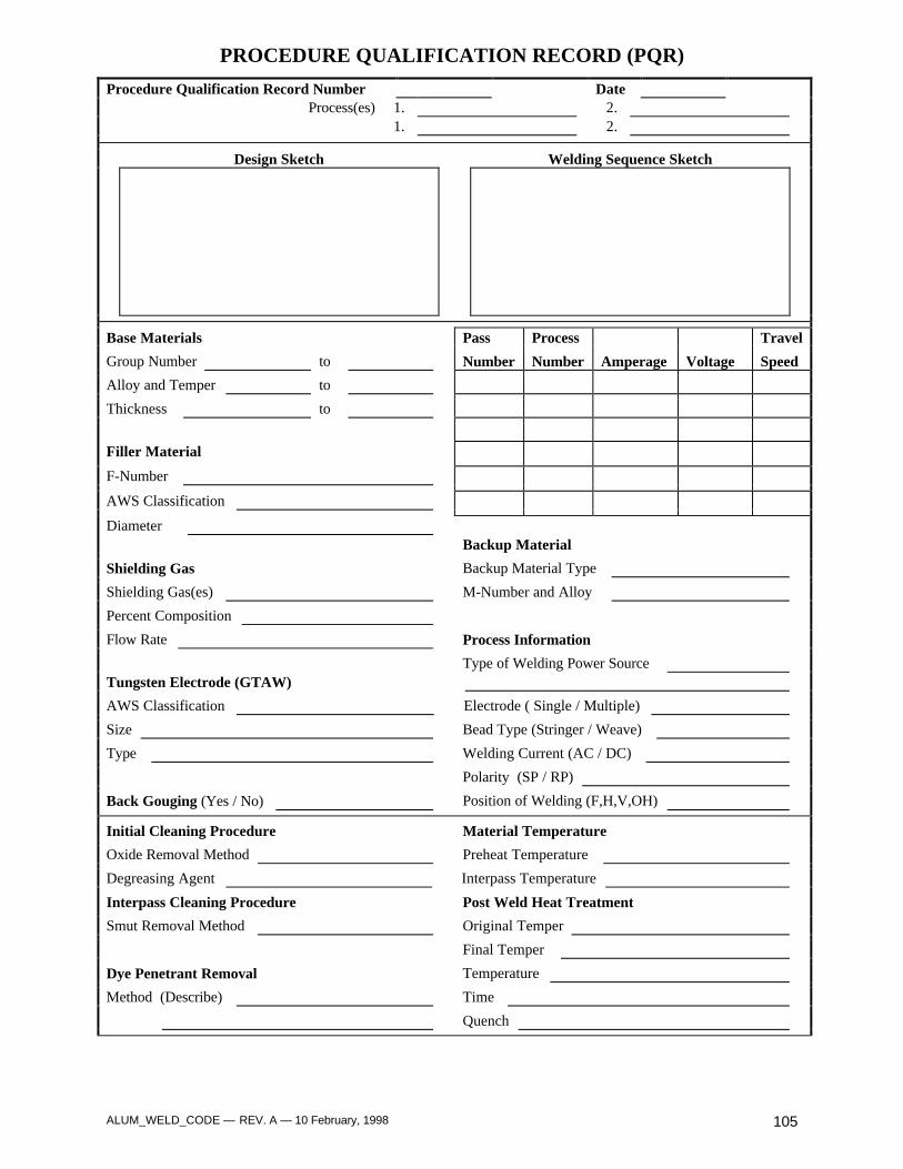
ALUM_WELD_CODE — REV. A — 10 February, 1998 105
PROCEDURE QUALIFICATION RECORD (PQR)
Procedure Qualification Record Number DateProcess(es) 1. 2.
1. 2.
Design Sketch Welding Sequence Sketch
Base Materials Pass Process Travel
Group Number to Number Number Amperage Voltage Speed
Alloy and Temper to
Thickness to
Filler Material
F-Number
AWS Classification
DiameterBackup Material
Shielding Gas Backup Material Type
Shielding Gas(es) M-Number and Alloy
Percent Composition
Flow Rate Process Information
Type of Welding Power SourceTungsten Electrode (GTAW)
AWS Classification Electrode ( Single / Multiple)
Size Bead Type (Stringer / Weave)
Type Welding Current (AC / DC)
Polarity (SP / RP)
Back Gouging (Yes / No) Position of Welding (F,H,V,OH)
Initial Cleaning Procedure Material Temperature
Oxide Removal Method Preheat Temperature
Degreasing Agent Interpass Temperature
Interpass Cleaning Procedure Post Weld Heat Treatment
Smut Removal Method Original Temper
Final Temper
Dye Penetrant Removal Temperature
Method (Describe) Time
Quench
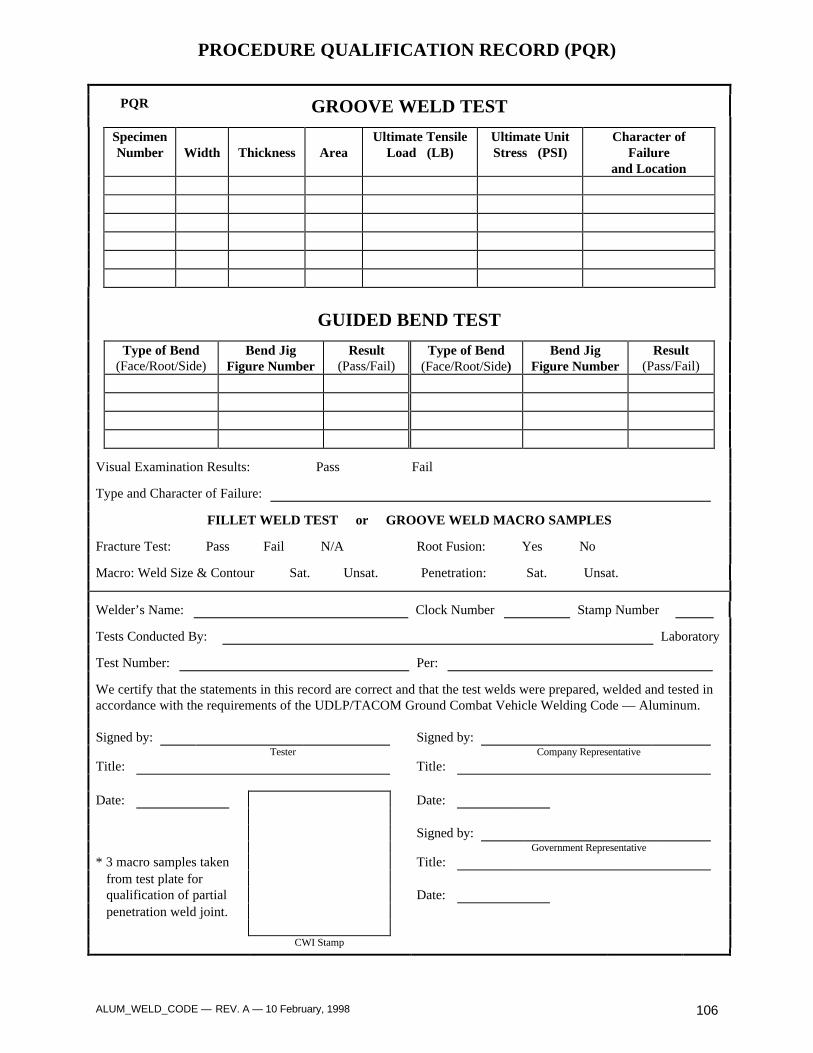
ALUM_WELD_CODE — REV. A — 10 February, 1998 106
PROCEDURE QUALIFICATION RECORD (PQR)
PQR GROOVE WELD TEST
SpecimenNumber Width Thickness Area
Ultimate TensileLoad (LB)
Ultimate UnitStress (PSI)
Character ofFailure
and Location
GUIDED BEND TEST
Type of Bend(Face/Root/Side)
Bend JigFigure Number
Result(Pass/Fail)
Type of Bend(Face/Root/Side)
Bend JigFigure Number
Result(Pass/Fail)
Visual Examination Results: Pass Fail
Type and Character of Failure:
FILLET WELD TEST or GROOVE WELD MACRO SAMPLES
Fracture Test: Pass Fail N/A Root Fusion: Yes No
Macro: Weld Size & Contour Sat. Unsat. Penetration: Sat. Unsat.
Welder’s Name: Clock Number Stamp Number
Tests Conducted By: Laboratory
Test Number: Per:
We certify that the statements in this record are correct and that the test welds were prepared, welded and tested inaccordance with the requirements of the UDLP/TACOM Ground Combat Vehicle Welding Code — Aluminum.
Signed by: Signed by:Tester Company Representative
Title: Title:
Date: Date:
Signed by:Government Representative
* 3 macro samples taken Title: from test plate for qualification of partial Date: penetration weld joint.
CWI Stamp
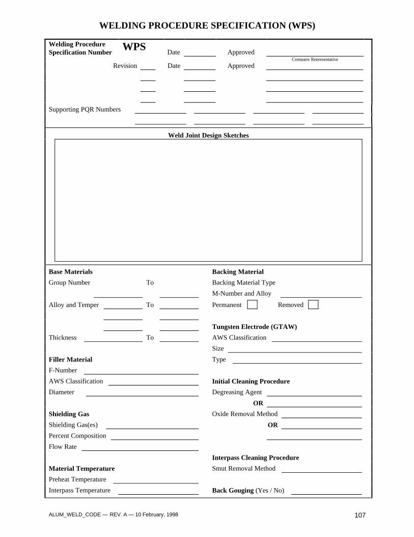
ALUM_WELD_CODE — REV. A — 10 February, 1998 107
WELDING PROCEDURE SPECIFICATION (WPS)
Welding ProcedureSpecification Number
WPSDate Approved
Company Representative
Revision Date Approved
Supporting PQR Numbers
Weld Joint Design Sketches
Base Materials Backing Material
Group Number To Backing Material Type
M-Number and Alloy
Alloy and Temper To Permanent Removed
Tungsten Electrode (GTAW)
Thickness To AWS Classification
Size
Filler Material Type
F-Number
AWS Classification Initial Cleaning Procedure
Diameter Degreasing Agent
OR
Shielding Gas Oxide Removal Method
Shielding Gas(es) OR
Percent Composition
Flow Rate
Interpass Cleaning Procedure
Material Temperature Smut Removal Method
Preheat Temperature
Interpass Temperature Back Gouging (Yes / No)

ALUM_WELD_CODE — REV. A — 10 February, 1998 108
WELDING PROCEDURE SPECIFICATION (WPS)
WPSPost Weld Heat Treatment
Original Temper Final Temper
Temperature Time
Quench
Dye Penetrant Removal Method (Describe)
Welding Sequence Sketches
Base Material Thickness
Position of Welding
Groove Angle
Weld Passes (Single, Multi.)
Amperage Range
Voltage Range
Travel Speed (IPM)
Shielding Gas Cup Size
Weld Bead Type
Welding Process
Welding Power Source
Welding Current (AC/DC)
Polarity (Straight/Reverse)
Welding Progression
Vertical Progression
Number of Electrodes
Spacing of Electrodes Note: The parameters listed above should be used as a guideline for welding same thickness materials, when welding dissimilar thickness’ or welding out of position, the welding parameters shall be maintained within the bolded range listed above.
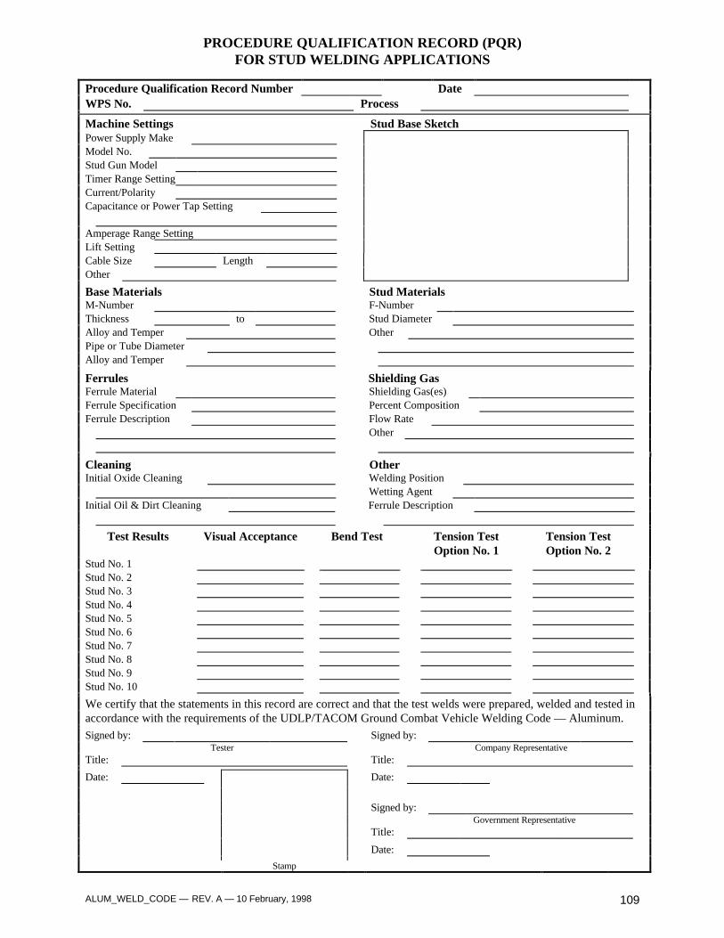
ALUM_WELD_CODE — REV. A — 10 February, 1998 109
PROCEDURE QUALIFICATION RECORD (PQR)FOR STUD WELDING APPLICATIONS
Procedure Qualification Record Number DateWPS No. Process
Machine Settings Stud Base SketchPower Supply MakeModel No.Stud Gun ModelTimer Range SettingCurrent/PolarityCapacitance or Power Tap Setting
Amperage Range SettingLift SettingCable Size LengthOther
Base Materials Stud MaterialsM-Number F-NumberThickness to Stud DiameterAlloy and Temper OtherPipe or Tube DiameterAlloy and Temper
Ferrules Shielding GasFerrule Material Shielding Gas(es)Ferrule Specification Percent CompositionFerrule Description Flow Rate
Other
Cleaning OtherInitial Oxide Cleaning Welding Position
Wetting AgentInitial Oil & Dirt Cleaning Ferrule Description
Test Results Visual Acceptance Bend Test Tension TestOption No. 1
Tension TestOption No. 2
Stud No. 1Stud No. 2Stud No. 3Stud No. 4Stud No. 5Stud No. 6Stud No. 7Stud No. 8Stud No. 9Stud No. 10
We certify that the statements in this record are correct and that the test welds were prepared, welded and tested inaccordance with the requirements of the UDLP/TACOM Ground Combat Vehicle Welding Code — Aluminum.
Signed by: Signed by:Tester Company Representative
Title: Title:
Date: Date:
Signed by:Government Representative
Title:
Date:
Stamp
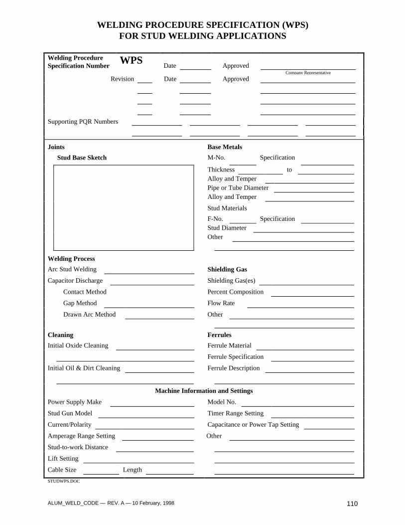
ALUM_WELD_CODE — REV. A — 10 February, 1998 110
WELDING PROCEDURE SPECIFICATION (WPS)FOR STUD WELDING APPLICATIONS
Welding ProcedureSpecification Number
WPSDate Approved
Company Representative
Revision Date Approved
Supporting PQR Numbers
Joints Base Metals
Stud Base Sketch M-No. Specification
Thickness toAlloy and TemperPipe or Tube DiameterAlloy and Temper
Stud Materials
F-No. SpecificationStud DiameterOther
Welding Process
Arc Stud Welding Shielding Gas
Capacitor Discharge Shielding Gas(es)
Contact Method Percent Composition
Gap Method Flow Rate
Drawn Arc Method Other
Cleaning Ferrules
Initial Oxide Cleaning Ferrule Material
Ferrule Specification
Initial Oil & Dirt Cleaning Ferrule Description
Machine Information and Settings
Power Supply Make Model No.
Stud Gun Model Timer Range Setting
Current/Polarity Capacitance or Power Tap Setting
Amperage Range Setting Other
Stud-to-work Distance
Lift Setting
Cable Size Length
STUDWPS.DOC

ALUM_WELD_CODE — REV. A — 10 February, 1998 111
PROCEDURE QUALIFICATION RECORD (PQR) MODIFIED
Procedure Qualification Record Number DateProcess(es) 1. 2.
1. 2.
Design Sketch Welding Sequence Sketch
Base Materials Pass Process Travel
Group Number to Number Number Amperage Voltage Speed
Alloy and Temper to
Thickness to
Filler Material
F-Number
AWS Classification
DiameterBackup Material
Shielding Gas Backup Material Type
Shielding Gas(es) M-Number and Alloy
Percent Composition
Flow Rate Process Information
Type of Welding Power SourceTungsten Electrode (GTAW)
AWS Classification Electrode ( Single / Multiple)
Size Bead Type (Stringer / Weave)
Type Welding Current (AC / DC)
Polarity (SP / RP)
Back Gouging (Yes / No) Position of Welding (F,H,V,OH)
Initial Cleaning Procedure Material Temperature
Oxide Removal Method Preheat Temperature
Degreasing Agent Interpass Temperature
Interpass Cleaning Procedure Post Weld Heat Treatment
Smut Removal Method Original Temper
Final Temper
Dye Penetrant Removal Temperature
Method (Describe) Time
Quench
PQRM.DOC
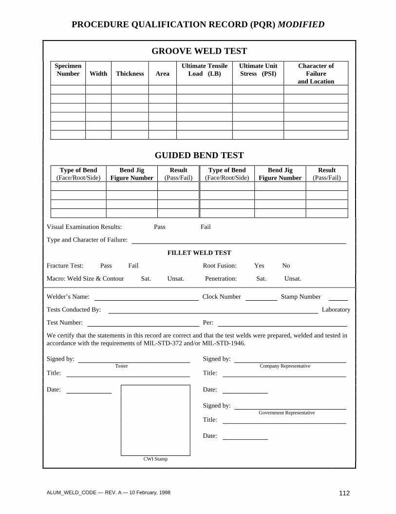
ALUM_WELD_CODE — REV. A — 10 February, 1998 112
PROCEDURE QUALIFICATION RECORD (PQR) MODIFIED
GROOVE WELD TEST
SpecimenNumber Width Thickness Area
Ultimate TensileLoad (LB)
Ultimate UnitStress (PSI)
Character ofFailure
and Location
GUIDED BEND TEST
Type of Bend(Face/Root/Side)
Bend JigFigure Number
Result(Pass/Fail)
Type of Bend(Face/Root/Side)
Bend JigFigure Number
Result(Pass/Fail)
Visual Examination Results: Pass Fail
Type and Character of Failure:
FILLET WELD TEST
Fracture Test: Pass Fail Root Fusion: Yes No
Macro: Weld Size & Contour Sat. Unsat. Penetration: Sat. Unsat.
Welder’s Name: Clock Number Stamp Number
Tests Conducted By: Laboratory
Test Number: Per:
We certify that the statements in this record are correct and that the test welds were prepared, welded and tested inaccordance with the requirements of MIL-STD-372 and/or MIL-STD-1946.
Signed by: Signed by:Tester Company Representative
Title: Title:
Date: Date:
Signed by:Government Representative
Title:
Date:
CWI Stamp

ALUM_WELD_CODE — REV. A — 10 February, 1998 113
WELDING PROCEDURE SPECIFICATION (WPS) MODIFIED
Welding ProcedureSpecification Number
WPSDate Approved
United Defense LP Weld Engineering Representative
Revision Date Approved
Supporting PQR Numbers
Weld Joint Design Sketches
Base Materials Backing Material
Group Number To Backing Material Type
M-Number and Alloy
Alloy and Temper To Permanent Removed
Tungsten Electrode (GTAW)
Thickness To AWS Classification
Size
Filler Material Type
F-Number
AWS Classification Initial Cleaning Procedure
Diameter Degreasing Agent
OR
Shielding Gas Oxide Removal Method
Shielding Gas(es) OR
Percent Composition
Flow Rate Interpass Cleaning ProcedureSmut Removal Method
Material Temperature
Preheat Temperature Back Gouging
Interpass Temperature (Yes / No)
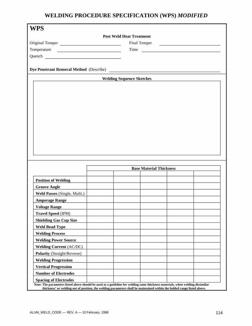
ALUM_WELD_CODE — REV. A — 10 February, 1998 114
WELDING PROCEDURE SPECIFICATION (WPS) MODIFIED
WPSPost Weld Heat Treatment
Original Temper Final Temper
Temperature Time
Quench
Dye Penetrant Removal Method (Describe)
Welding Sequence Sketches
Base Material Thickness
Position of Welding
Groove Angle
Weld Passes (Single, Multi.)
Amperage Range
Voltage Range
Travel Speed (IPM)
Shielding Gas Cup Size
Weld Bead Type
Welding Process
Welding Power Source
Welding Current (AC/DC)
Polarity (Straight/Reverse)
Welding Progression
Vertical Progression
Number of Electrodes
Spacing of Electrodes Note: The parameters listed above should be used as a guideline for welding same thickness materials, when welding dissimilar thickness’ or welding out of position, the welding parameters shall be maintained within the bolded range listed above.

ALUM_WELD_CODE — REV. A — 10 February, 1998 115
ALUMINUM WELDER QUALIFICATION TEST RECORD
Company Name Company Location Test ID No.
Name Badge No. Date
Welding Process Manual Semiautomatic Mechanized
Material Number Alloy to Thickness
Filler Metal Specification Class Diameter
Position 1G 2G 3G (up) 4G Backing material
In accordance with procedure specification no.
Retest Yes No If a retest, was further training or practice provided? Yes No
VISUAL INSPECTION
Accept Reject Accept RejectCracks 0.1” max. UnderfillCraters Filled ReinforcementSmooth Weld/BaseTransition
RADIOGRAPHIC INSPECTION
Test/Film ID No. Results Remarks
Accept Reject
Radiographer Date
GUIDED BEND TEST
Specimen type Thickness,in.
Results Remarks
Accept Reject Accept Reject Accept Reject Accept Reject
I certify that the statements in this record are correct and that the test welds were prepared, welded, and tested inaccordance with the requirements of the UDLP/TACOM Ground Combat Vehicle Welding Code-Aluminum.
Signed byTest Administrator
Title
Date
CWI Stamp
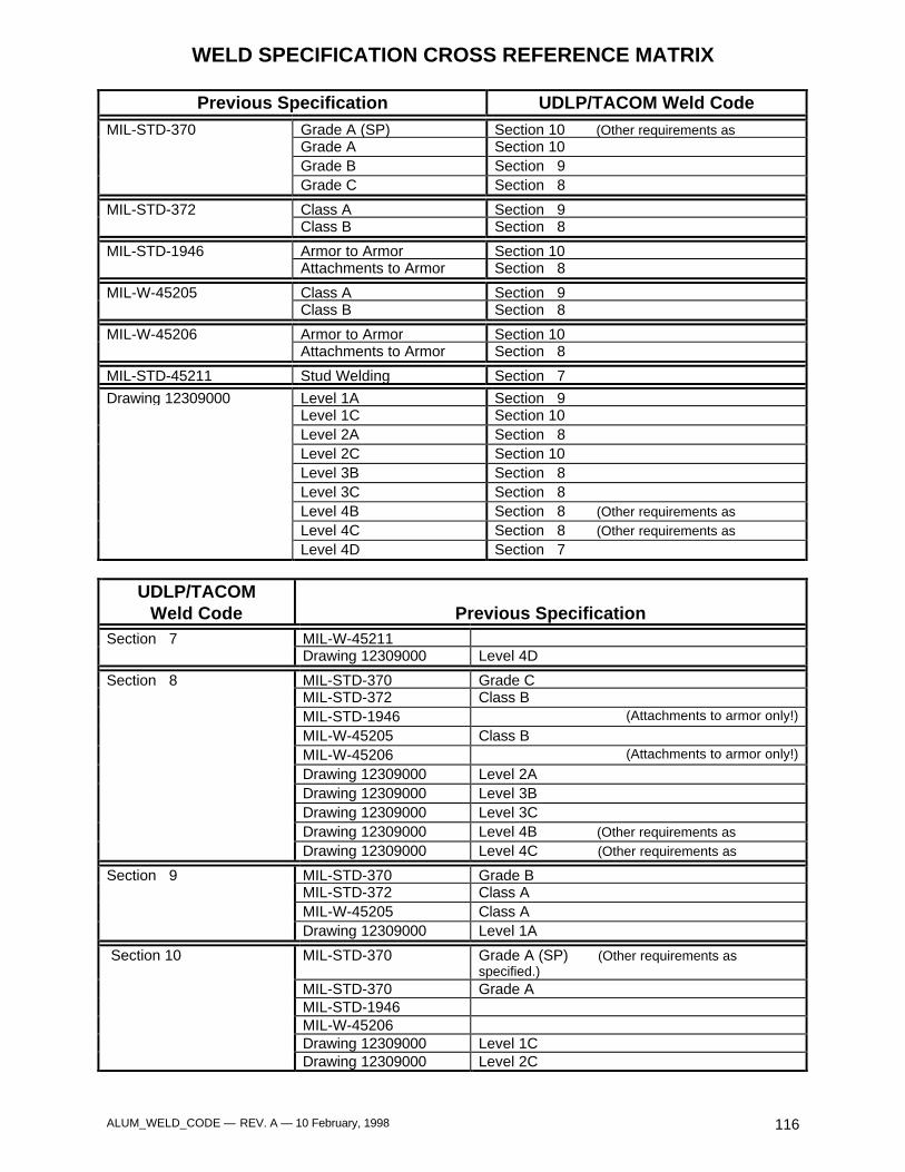
ALUM_WELD_CODE — REV. A — 10 February, 1998 116
WELD SPECIFICATION CROSS REFERENCE MATRIX
Previous Specification UDLP/TACOM Weld CodeMIL-STD-370 Grade A (SP) Section 10 (Other requirements as
Grade A Section 10Grade B Section 9Grade C Section 8
MIL-STD-372 Class A Section 9Class B Section 8
MIL-STD-1946 Armor to Armor Section 10Attachments to Armor Section 8
MIL-W-45205 Class A Section 9Class B Section 8
MIL-W-45206 Armor to Armor Section 10Attachments to Armor Section 8
MIL-STD-45211 Stud Welding Section 7
Drawing 12309000 Level 1A Section 9Level 1C Section 10Level 2A Section 8Level 2C Section 10Level 3B Section 8Level 3C Section 8Level 4B Section 8 (Other requirements as
specified.)Level 4C Section 8 (Other requirements asspecified.)Level 4D Section 7
UDLP/TACOMWeld Code Previous Specification
Section 7 MIL-W-45211Drawing 12309000 Level 4D
Section 8 MIL-STD-370 Grade CMIL-STD-372 Class BMIL-STD-1946 (Attachments to armor only!)
MIL-W-45205 Class BMIL-W-45206 (Attachments to armor only!)
Drawing 12309000 Level 2ADrawing 12309000 Level 3BDrawing 12309000 Level 3CDrawing 12309000 Level 4B (Other requirements as
specified.)Drawing 12309000 Level 4C (Other requirements asspecified.)
Section 9 MIL-STD-370 Grade BMIL-STD-372 Class AMIL-W-45205 Class ADrawing 12309000 Level 1A
Section 10 MIL-STD-370 Grade A (SP) (Other requirements asspecified.)
MIL-STD-370 Grade AMIL-STD-1946MIL-W-45206Drawing 12309000 Level 1CDrawing 12309000 Level 2C
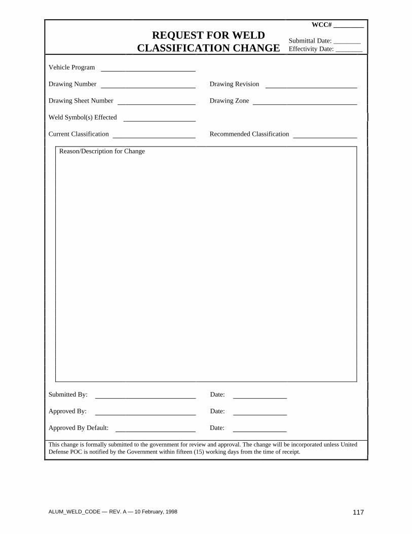
ALUM_WELD_CODE — REV. A — 10 February, 1998 117
REQUEST FOR WELDCLASSIFICATION CHANGE
WCC# _________
Submittal Date: ________Effectivity Date: ________
Vehicle Program
Drawing Number Drawing Revision
Drawing Sheet Number Drawing Zone
Weld Symbol(s) Effected
Current Classification Recommended Classification
Reason/Description for Change
Submitted By: Date:
Approved By: Date:
Approved By Default: Date:
This change is formally submitted to the government for review and approval. The change will be incorporated unless UnitedDefense POC is notified by the Government within fifteen (15) working days from the time of receipt.

ALUM_WELD_CODE — REV. A — 10 February, 1998 118

ALUM_WELD_CODE — REV. A — 10 February, 1998 119
APPENDIX B
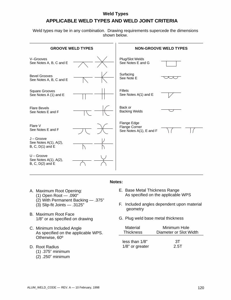
ALUM_WELD_CODE — REV. A — 10 February, 1998 120
Weld Types
APPLICABLE WELD TYPES AND WELD JOINT CRITERIA
GROOVE WELD TYPES NON-GROOVE WELD TYPES
Plug/Slot WeldsSee Notes E and G
Flange EdgeFlange CornerSee Notes A(1), E and F
SurfacingSee Note E
FilletsSee Notes A(1) and E
Back orBacking Welds
V–GroovesSee Notes A, B, C and E
Bevel GroovesSee Notes A, B, C and E
Square GroovesSee Notes A (1) and E
Flare BevelsSee Notes E and F
Flare VSee Notes E and F
J – GrooveSee Notes A(1), A(2),B, C, D(1) and E
U – GrooveSee Notes A(1), A(2),B, C, D(2) and E
A. Maximum Root Opening:(1) Open Root — .090"(2) With Permanent Backing — .375"(3) Slip-fit Joints — .3125"
B. Maximum Root Face1/8" or as specified on drawing
C. Minimum Included AngleAs specified on the applicable WPS.Otherwise, 60º
D. Root Radius(1) .375 minimum(2) .250 minimum
″″
Notes:
E. Base Metal Thickness RangeAs specified on the applicable WPS
F. Included angles dependent upon material geometry
G. Plug weld base metal thickness
Material Minimum Hole Thickness Diameter or Slot Width
less than 1/8" 3T 1/8" or greater 2.5T
Weld types may be in any combination. Drawing requirements supercede the dimensions shown below.