udc 621 . 791 . 053 : 539 . 55 metallurgical controlling ... · impact test for the weld metal was...
TRANSCRIPT
NIPPON STEEL TECHNICAL REPORT No. 95 January 2007
- 76 -
UDC 621 . 791 . 053 : 539 . 55
*1 Steel Laboratories*2 Plate Division
*3 Structural Division
Metallurgical Controlling Factors for Toughnessof Multi-layered Weld Metal in Beam-to-column Connections-Application of Fraction of Columnar Structure in Assessing Toughness
of Weld Metal Derived from YGW18 Solid Wire-Yuji HASHIBA*1 Toshiei HASEGAWA*1
Shigeru OHKITA*1 Yuzuru YOSHIDA*2
Yasumi SHIMURA*3
Abstract
Metallurgical controlling factors for toughness of multi-layered weld metal in
beam-to-column connections were investigated by considering the heterogeneity of
microstructure as a dominant factor of scatter of Charpy absorbed energy. The frac-
tion of as-welded zone of weld metal included in notch part of the test piece for
Charpy impact test was defined as fraction of columnar structure (αααααC ). Charpy
impact test for the weld metal was examined with constant αααααC (αααααC
: 0% and 80%) to
reduce the heterogeneity of microstructure as much as possible. The validity of αααααC
as an index of heterogeneity of microstructure was verified, and the clarification of
the influence of heat input and interpass temperature on the toughness of weld metal
was tried.
1. IntroductionBeam-to-column connections are essential structural components
for the seismic resistance of a building steel frame. Against the back-ground of increased interest in the seismic performance of buildingsespecially after the Hanshin-Awaji Earthquake in 1995, many stud-ies have been conducted regarding the performance of weld joints1-11)
and increasingly stringent measures for improving the performancehave been proposed and practically applied. Lately, to prevent brittlefracture of weld joints, there have been various proposals to specifyquality requirements for many types of weld joints of a steel columnin more detail in consideration of required performance of a buildingand stress imposed on structural members. In the meantime, currentdesign standards require higher toughness for a beam-to-column con-nection than earlier standards did; the toughness presently required
for this type of connection is generally 70 J or more in terms of theCharpy absorbed energy at 0˚C (vE
0 )1).
Multi-pass CO2 arc welding is commonly employed for beam-
to-column connections, and solid wires such as YGW11 and YGW18under JIS Z 3312 are widely used as the welding consumables forthe application.
To prevent poor performance of weld joints due to excessive heatinput or interpass temperature, steel frame fabricators specify upperlimits of these parameters for field practice. Since the principal fac-tors that determine the mechanical properties of a weld metal are itschemical composition and thermal history (cooling rate), it is cur-rently a usual control practice for field welding work to specify up-per limits of heat input and interpass temperature for various typesof welding consumables.

NIPPON STEEL TECHNICAL REPORT No. 95 January 2007
- 77 -
From the viewpoint of operating efficiency, however, setting up-per limits for these parameters lowers deposition rate of weld metaland increases cooling time after each pass, which significantly dete-riorate work efficiency. For rational welding work, therefore, it isdesirable to have a means for predicting an optimum welding condi-tion to realize required performance of a weld metal.
From the viewpoint of development of welding consumables, onthe other hand, it is important to clarify the relationship between theperformance of a weld metal and cooling rate. However, many paststudies showed that the Charpy absorbed energy of a weld metal at0˚C often fluctuated remarkably depending on the combination ofwelding consumables and work conditions (heat input and interpasstemperature)2). A factor causing the fluctuation of the absorbed en-ergy is the possibility that the ductile-brittle transition temperatureof the weld metal in question is near 0˚C, and another is the fact thatthe weld metal at the notched position of a Charpy test piece hasdifferent metallurgical structures from one to another because of com-plex thermal history and varied shapes of weld-metal layers, whichare inevitable with multi-pass welding.
In consideration of the above, an investigation was conducted onthe relationship between Charpy absorbed energy and cooling ratethrough a series of test using YGW18 weld metal, which was widelyused for beam-to-column joints. Then, understanding that the struc-tural unevenness of weld metal due to the changing thermal historypeculiar to multi-pass welding was a main governing factor of itstoughness, an attempt was made to clarify the relationship betweenthe toughness and cooling rate of weld metal taking the macroscopicstructural heterogeneity of weld metal into consideration by makinga correlation between Charpy absorbed energy and macroscopic struc-tural fractions of weld metal at the notched position of a test piece.
2. Introduction of Fraction of Columnar StructureαααααCThe mechanical properties of weld metal depend on the structure
that is determined by its chemical composition and cooling rate, whichis dependent on thermal conditions such as heat input and interpasstemperature. In the present test, it was assumed that the metallo-graphic structure of the notched position of a test piece was differentfrom one to another, and this caused the test results of Charpy ab-sorbed energy of multi-layered weld metal to fluctuate. That is, bymulti-pass welding, the structure of an as-welded zone of the weldmetal of a previous pass undergoes reheating during a succeedingpass, and a reheated structure having mechanical properties differ-ent from those of the as-welded zone forms as a result. For this rea-son, even if test pieces are cut out from the same position in the
thickness direction of specimen joints, the ratio between the as-weldedand reheated zones of weld metal at the notched position is likely tobe different with different Charpy test pieces, or different weld jointsto evaluate, because of the difference in weld-metal layers and dis-turbances in work conditions.
In view of the above, the fraction of columnar structure (αC
) wasdefined as an index to express the heterogeneity of weld metal struc-ture, which it was assumed to be different from test piece to testpiece. Fig. 1 schematically shows weld-metal layers of a weld joint;the structures of subject weld metal at the notched position of a Charpytest piece are classified into an as-welded zone in columnar structureand a reheated zone mainly in granular structure. A more preciseway of classification would be necessary metallographically, but touse as simple an index as possible, it was considered that this classi-fication into two would be adequate, and the ratio of the as-weldedzone to the whole structure (α
C ≡ as-welded zone / (as-welded zone
+ reheated zone)) at the notched position of a Charpy test piece wasdefined as its fraction of columnar structure.
3. Test Method3.1 Investigation of toughness fluctuation of YGW11 and YGW18
multi-layered weld metalsBefore calculating the relationship between cooling time and
Charpy absorbed energy of YGW18 weld metal, a series of testswere conducted to investigate the actual fluctuation of Charpy ab-sorbed energy of YGW11 and YGW18 weld metals and that of α
C of
different test pieces.Fig. 2 (a) shows the shape and dimensions of the T-joint speci-
mens (weld length of 300 mm) prepared for the test. The thicknessof the plate corresponding to a skin plate of a square-section columnwas 36 mm for all the specimens, and the thickness (t) of the platecorresponding to a flange of a beam was changed to 19, 25, 32 and40 mm, and its bevel angle to 20, 30 and 35˚. Plates of JIS SN490steel and solid wires 1.4 mm in diameter of YM-26 and YM-55C(products of Nippon Steel & Sumikin Welding Co., Ltd. correspond-ing to YGW11 and YGW18 under JIS Z 3312, respectively) wereused for the specimen joints.
The welding method was underhand, semi-automatic, multi-pass,CO
2-gas-shielded arc welding by continuous, reversing build-up se-
quence. In the field welding practice of beam-to-column joints, heatinput is not always the same in all the passes: the heat input of theroot pass is often lower than that of passes for upper layers. For thisreason, heat input of different passes was not controlled to a constantvalue in the present test. Furthermore, the final layer was formed intwo-passes for all the specimen joints, but each of the other layers
Fig. 1 Definition of fraction of columnar structure

NIPPON STEEL TECHNICAL REPORT No. 95 January 2007
- 78 -
below it were either formed in a single pass (build-up condition D1in Table 1) or in two passes per layer after the interpass temperaturereached 350˚C (build-up condition D2 in Table 1).
Table 1 shows the combinations of plate thicknesses, weldingconsumables and bevel angle, and the welding conditions (heat in-put, maximum interpass temperature, etc) for the test. The heat inputof the pass at the position corresponding to 1/4 t was as follows: 3.0to 3.3 kJ/mm for YGW11 and plates 19 and 25 mm in thickness; 2.0
to 4.2 and 4.9 to 5.1 kJ/mm for YGW11 and plates 32 and 40 mm inthickness, respectively; and 2.8 to 3.5 kJ/mm for YGW18 and plates32 mm in thickness.
Charpy test pieces were cut out from the 1/4-t position of thebeam flange plates nearer to the upper side, additional test pieceswere taken from the specimens using plates 32 and 40 mm in thick-ness at the 3/4-t position nearer the root. The notch was cut at thecenter of the weld metal of each test piece.3.2 Investigation of toughness of YGW18 multi-layered weld
metal with constant columnar structure fractionAfter the above, specimen joints were prepared using YGW18
weld metal and minimizing disturbance in welding conditions, cutout test pieces having the same columnar structure fraction α
C from
specimen joints welded under the same conditions, and subjected toa Charpy impact test. The objects of this test were to verify the ad-equacy of the columnar structure fraction as an indicator of struc-tural heterogeneity, to calculate the cooling time from 800 to 500˚Cas a function of heat input and interpass temperature, and to clarifythe effects of heat input and interpass temperature over the tough-ness of weld metal.
The specimen joints were butt joints (weld length of 250 mm)simulating a beam-to-column connection; Fig. 2 (b) shows their shapeand dimensions. Plates of JIS SN490 steel 40 mm in thickness andsolid wires 1.4 mm in diameter of YM-55C (a product of NipponSteel & Sumikin Welding Co., Ltd. corresponding to YGW18 underJIS Z 3312) were used. A total of 11 welding conditions combiningthe following were tested: heat input of 3.0, 4.0 and 5.0 kJ/mm andinterpass temperatures of 350, 400, 450 and 500˚C. To minimize dis-turbance in welding work, all the passes were welded under the sameheat input. Because interpass temperature was set higher than in nor-mal field practice, and to stably realize the intended interpass tem-
Fig. 2 Schematic illustrations of test joint geometry
Table 1 Welding conditions of test joints
No.
1901190219032502250332023203320432103211321340024003320632073208320932153216
WeldingWire
YGW11
YGW18
Platethickness
(mm)
19
25
32
40
32
Grooveangle( ˚ )
25303530353035253025303035252530302530
Totalpass
4456788111188910888899
Current(A)
380400
400-410420
400-420380
360-400300-420340-390390-420380-440
400380-420300-400300-400380-400380-400360-410360-420
Voltage(V)
40404244444242
32-464042424242
32-4433-44
4444
42-4040-42
Heatinput
(kJ/mm)
2.3-3.12.3-3.32.7-3.73.2-4.02.4-3.62.7-4.62.2-4.81.2-3.22.6-4.12.7-3.62.5-3.82.7-5.92.7-5.31.7-3.81.8-4.11.9-3.92.1-3.42.2-3.62.5-4.2
Maximuminterpass
temperature(˚C)470491516513553502520
>= 350550440485596599
-----
530
* Build-up conditionsD1 Dual-pass per layer only in final layerD2 Dual-pass per layer after reaching an interpass temperature of 350˚C
Welding conditions
Build-upcondition*
D1
D2
D1
D1

NIPPON STEEL TECHNICAL REPORT No. 95 January 2007
- 79 -
perature near the final layer, from which each test piece would be cutout, the specimen joints were soaked in a furnace of 350˚C and thensubjected to fully automatic welding by a welding robot under con-ditions controlled to the respectively specified heat input and interpasstemperatures.
For the control of interpass temperature, the temperature wasmeasured at a plate surface position at the center of the weld lengthand 10 mm away from the upper end of the bevel. The thermal his-tory of weld metal was measured with a thermocouple submerged inthe molten pool; as a result, it was possible to accurately measure thecooling time from 800 to 500˚C.
The Charpy test pieces were cut out under microstructural obser-vation so that α
C at the notch position was 0% (100% reheated zone)
or 80% (mostly as-welded zone) as schematically shown in Fig. 3.
4. Test Results and Discussion4.1 Fluctuation of Charpy absorbed energy of YGW11 and YGW
18 multi-layered weld metalsFirst, the results of the test of 3.1 above are described. The car-
bon equivalents of the welding consumables YGW11 and YGW18used for the test were as follows: 0.271 to 0.296 mass % with YGW11and 0.328 to 0.365 mass % with YGW18. Here, the carbon equiva-lent (Ceq) was calculated according to the equation Ceq = C + Mn/6+ Si/24 + Ni/40 + Cr/5 + Mo/4 + V/14 (in mass %).
The value of αC of each test piece was determined through struc-
tural observation of the fracture surface at the notch position afterthe Charpy impact test. Fig. 4 shows the relationship between theCharpy absorbed energy at 0˚C (vE
0 ) and α
C .
The Charpy absorbed energy at 0˚C of YGW18 weld metal was70 J or more in a wide range of α
C , and its fluctuation was small.
The value of vE0 tended to decease as α
C increased.
On the other hand, while the absorbed energy of YGW11 weldmetal fluctuated more than that of YGW18 did, the tendency of vE
0
to decrease with larger values of αC was substantially the same as
that of YGW18. This is presumably due to the difference in tough-ness between the as-welded and reheated zones; it suggests the pos-sibility that the reheated zone, the structure of which is finer thanthat of the as-welded zone, has a higher toughness.
In this test, vE0 and α
C were correlated as shown in Fig. 4 be-
cause it was assumed that the fluctuation of αC was mainly respon-
sible for that of vE0. However, the correlation between the two was
not very clear especially with YGW11 weld metal, and the possibil-ity of there being other influencing factors could not be ignored. Oneof the reasons why the fluctuation of vE
0 could not be explained
using only αC was presumably that, in the present test, the welding
work conditions (heat input, interpass temperature, shapes of weld-metal layers, etc.) at the test piece position changed from specimento specimen.4.2 Charpy absorbed energy of multi-layered YGW18 weld metal
with constant columnar structure fractionIn the preceding sub-section 4.1, it was pointed out that the fluc-
tuation of welding conditions was a suspected factor of the fluctua-tion of vE
0. This sub-section describes the results of the test of 3.2
above, where the fluctuation of welding conditions (heat input andinterpass temperature) was minimized.
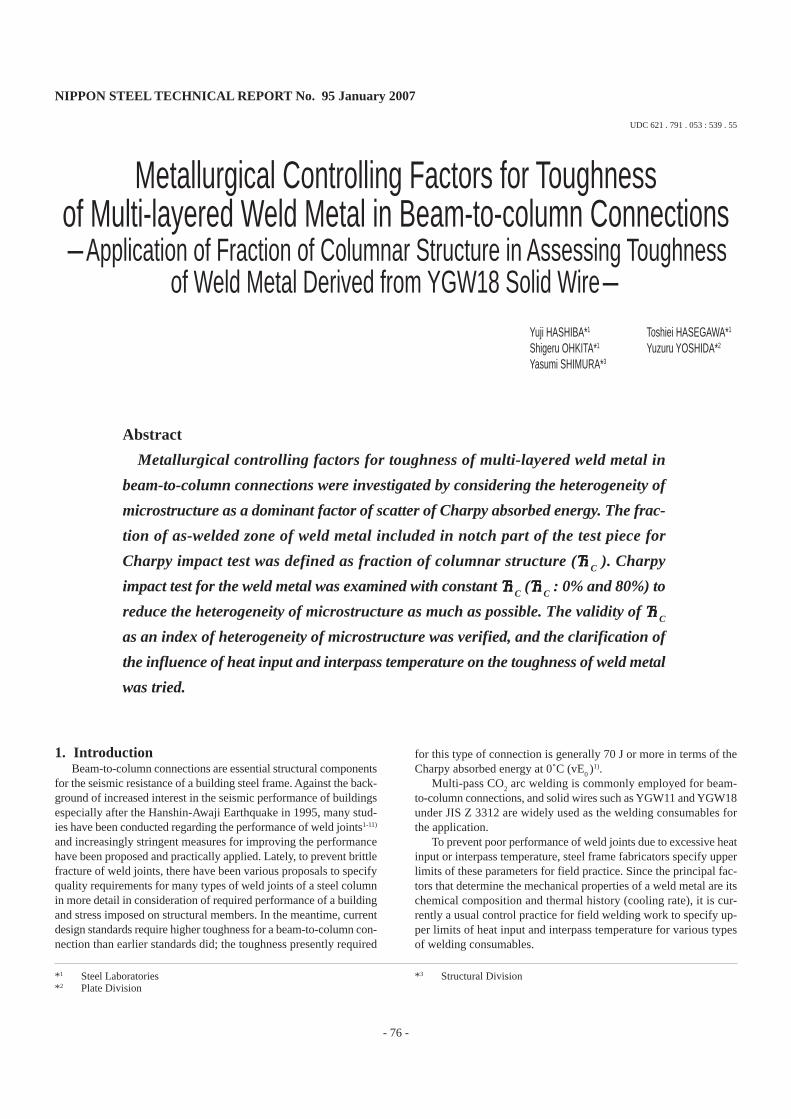
Fig. 5 shows the relationship of vE0 with heat input and interpass
temperature. Although vE0 showed no clear tendencies with respect
to changes in heat input or interpass temperature in the test results of4.1, vE
0 of test pieces having the same value of α
C tended to de-
crease as heat input and interpass temperature increased, as the graphclearly shows. With multi-layered YGW18 weld metal, vE
0 decreased
under most of the welding conditions as αC decreased, or as the ratio
of the reheated zone increased: the difference between vE0 when α
C
was 80% (hereinafter written as vE0 (α
C =
80%)) and that when α
C
was 0% (hereinafter written as vE0 (α
C =
0%)) was approximately
40 J at the largest.This points to a conclusion that the toughness of weld metal fluc-
tuates significantly owing to the facts that heat input and interpasstemperature are different from joint to joint in the field practice ofmulti-pass welding, and that the ratios of the as-welded and reheatedzones at the notch position are different from test piece to test piece.Accordingly, one can understand that the fact described in 4.1 thatthe toughness of YGW18 weld metal tended to decrease as α
C in-
creased is due to the differences in the heat input and interpass tem-perature at the test piece position between different specimen joints.
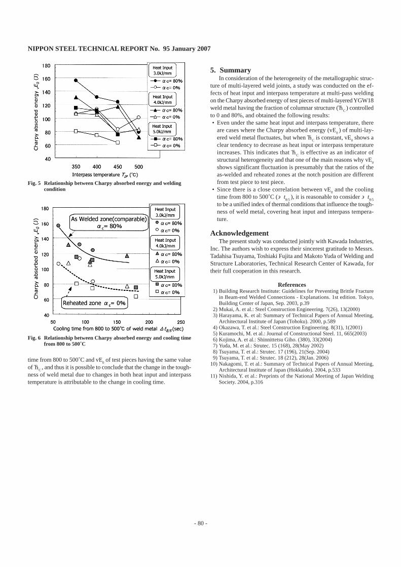
Fig. 6 shows the relationship between the cooling time from 800to 500˚C (Δt
8/5 ) and vE
0. Both vE
0 (α
C =
80%) and vE
0 (α
C =
0%)
tended to decrease as Δt8/5
increased. As far as the conditions of thepresent test are concerned, there is a correlation between the cooling
Fig. 3 Position of test pieces for Charpy impact test
Fig. 4 Relationship between Charpy absorbed energy and fraction ofcolumnar structure
NIPPON STEEL TECHNICAL REPORT No. 95 January 2007
- 80 -
time from 800 to 500˚C and vE0 of test pieces having the same value
of αC , and thus it is possible to conclude that the change in the tough-
ness of weld metal due to changes in both heat input and interpasstemperature is attributable to the change in cooling time.
Fig. 5 Relationship between Charpy absorbed energy and weldingcondition
Fig. 6 Relationship between Charpy absorbed energy and cooling timefrom 800 to 500˚C
5. SummaryIn consideration of the heterogeneity of the metallographic struc-
ture of multi-layered weld joints, a study was conducted on the ef-fects of heat input and interpass temperature at multi-pass weldingon the Charpy absorbed energy of test pieces of multi-layered YGW18weld metal having the fraction of columnar structure (α
C ) controlled
to 0 and 80%, and obtained the following results:• Even under the same heat input and interpass temperature, there
are cases where the Charpy absorbed energy (vE0 ) of multi-lay-
ered weld metal fluctuates, but when αC is constant, vE
0 shows a
clear tendency to decrease as heat input or interpass temperatureincreases. This indicates that α
C is effective as an indicator of
structural heterogeneity and that one of the main reasons why vE0
shows significant fluctuation is presumably that the ratios of theas-welded and reheated zones at the notch position are differentfrom test piece to test piece.
• Since there is a close correlation between vE0 and the cooling
time from 800 to 500˚C (Δt8/5
), it is reasonable to consider Δt8/5
to be a unified index of thermal conditions that influence the tough-ness of weld metal, covering heat input and interpass tempera-ture.
AcknowledgementThe present study was conducted jointly with Kawada Industries,
Inc. The authors wish to express their sincerest gratitude to Messrs.Tadahisa Tsuyama, Toshiaki Fujita and Makoto Yuda of Welding andStructure Laboratories, Technical Research Center of Kawada, fortheir full cooperation in this research.
References 1) Building Research Institute: Guidelines for Preventing Brittle Fracture
in Beam-end Welded Connections - Explanations. 1st edition. Tokyo,Building Center of Japan, Sep. 2003, p.39
2) Mukai, A. et al.: Steel Construction Engineering. 7(26), 13(2000) 3) Harayama, K. et al: Summary of Technical Papers of Annual Meeting,
Architectural Institute of Japan (Tohoku). 2000, p.589 4) Okazawa, T. et al.: Steel Construction Engineering. 8(31), 1(2001) 5) Kuramochi, M. et al.: Journal of Constructional Steel. 11, 665(2003) 6) Kojima, A. et al.: Shinnittetsu Giho. (380), 33(2004) 7) Yuda, M. et al.: Strutec. 15 (168), 28(May 2002) 8) Tsuyama, T. et al.: Strutec. 17 (196), 21(Sep. 2004) 9) Tsuyama, T. et al.: Strutec. 18 (212), 28(Jan. 2006)10) Nakagomi, T. et al.: Summary of Technical Papers of Annual Meeting,
Architectural Institute of Japan (Hokkaido). 2004, p.53311) Nishida, Y. et al.: Preprints of the National Meeting of Japan Welding
Society. 2004, p.316