type 3522-1 and type 3522-7 pneumatic control valves type
TRANSCRIPT
Data Sheet T 8822 EN
Associated Information Sheet for valves T 8000-XAssociated Information Sheet for actuators T 8300Associated Information Sheet for accessories T 8350
Edition December 2016
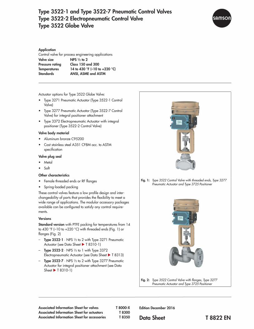
Fig. 1: Type 3522 Control Valve with threaded ends, Type 3277 Pneumatic Actuator and Type 3725 Positioner
Fig. 2: Type 3522 Control Valve with flanges, Type 3277 Pneumatic Actuator and Type 3725 Positioner
Actuator options for Type 3522 Globe Valve: • Type 3271 Pneumatic Actuator (Type 3522‑1 Control
Valve) • Type 3277 Pneumatic Actuator (Type 3522‑7 Control
Valve) for integral positioner attachment • Type 3372 Electropneumatic Actuator with integral
positioner (Type 3522‑2 Control Valve)
Valve body material • Aluminum bronze C95200 • Cast stainless steel A351 CF8M acc. to ASTM
specification
Valve plug seal • Metal • Soft
Other characteristics • Female threaded ends or RF flanges • Spring‑loaded packing
These control valves feature a low profile design and inter‑changeability of parts that provides the flexibility to meet a wide range of applications. The modular accessory packages available can be configured to satisfy any control require‑ments.
VersionsStandard version with PTFE packing for temperatures from 14 to 430 °F (–10 to +220 °C) with threaded ends (Fig. 1) or flanges (Fig. 2) – Type 3522-1 · NPS ½ to 2 with Type 3271 Pneumatic
Actuator (see Data Sheet u T 8310‑1) – Type 3522-2 · NPS ½ to 1 with Type 3372
Electropneumatic Actuator (see Data Sheet u T 8313) – Type 3522-7 · NPS ½ to 2 with Type 3277 Pneumatic
Actuator for integral positioner attachment (see Data Sheet u T 8310‑1)
Type 3522-1 and Type 3522-7 Pneumatic Control ValvesType 3522-2 Electropneumatic Control ValveType 3522 Globe Valve
ApplicationControl valve for process engineering applicationsValve size NPS ½ to 2Pressure rating Class 150 and 300Temperatures 14 to 430 °F (–10 to +220 °C)Standards ANSI, ASME and ASTM
2 T 8822 EN
Further options – Adjustable graphite packing – Stellited® trim – Additional handwheel · see Data Sheet u T 8310‑1 – NACE version acc. to ISO 15156, MR0103:2007,
MR0175:2002
Fail-safe actionDepending on how the springs are arranged in the pneumatic actuator (see Data Sheets u T 8310‑1), the valve has two dif‑ferent fail‑safe positions effective upon air supply failure: – Actuator stem extends (air-to-open/fail-close): The actua‑
tor spring closes the valve upon air supply failure. – Actuator stem retracts (air-to-close/fail-open): The actua‑
tor spring opens the valve upon air supply failure.
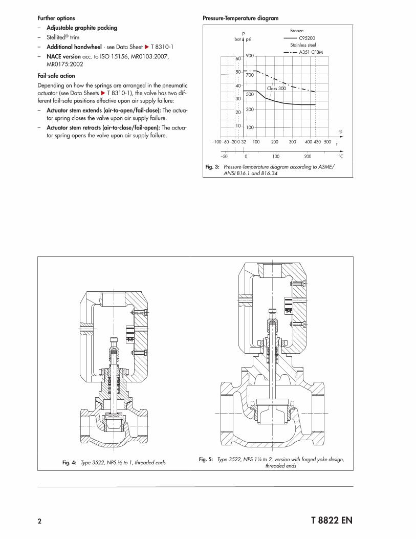
Pressure-Temperature diagram
C95200
A351 CF8M
–100 –60 –20 0 32 100 200 400300 500430
bar psi
90060
50700
40
50030
30020
10 100
Class 300
–50 0 100 200
p
t
Bronze
Stainless steel
°F
°C
Fig. 3: Pressure-Temperature diagram according to ASME/ANSI B16.1 and B16.34
Fig. 4: Type 3522, NPS ½ to 1, threaded ends Fig. 5: Type 3522, NPS 1¼ to 2, version with forged yoke design, threaded ends
T 8822 EN 3
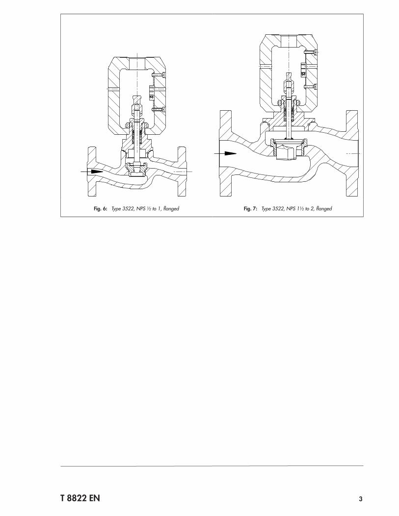
Fig. 6: Type 3522, NPS ½ to 1, flanged Fig. 7: Type 3522, NPS 1½ to 2, flanged
4 T 8822 EN
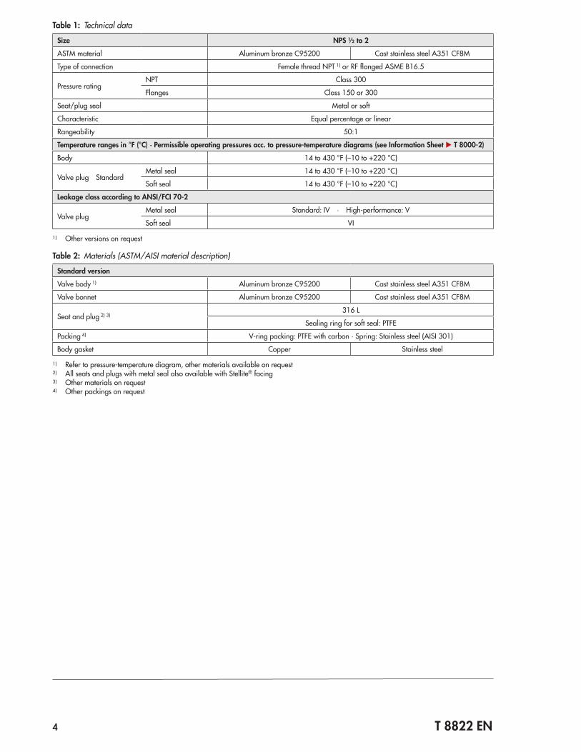
Table 1: Technical data
Size NPS ½ to 2
ASTM material Aluminum bronze C95200 Cast stainless steel A351 CF8M
Type of connection Female thread NPT 1) or RF flanged ASME B16.5
Pressure ratingNPT Class 300
Flanges Class 150 or 300
Seat/plug seal Metal or soft
Characteristic Equal percentage or linear
Rangeability 50:1
Temperature ranges in °F (°C) · Permissible operating pressures acc. to pressure-temperature diagrams (see Information Sheet u T 8000-2)
Body 14 to 430 °F (–10 to +220 °C)
Valve plug StandardMetal seal 14 to 430 °F (–10 to +220 °C)
Soft seal 14 to 430 °F (–10 to +220 °C)
Leakage class according to ANSI/FCI 70-2
Valve plugMetal seal Standard: IV · High‑performance: V
Soft seal VI
1) Other versions on request
Table 2: Materials (ASTM/AISI material description)
Standard version
Valve body 1) Aluminum bronze C95200 Cast stainless steel A351 CF8M
Valve bonnet Aluminum bronze C95200 Cast stainless steel A351 CF8M
Seat and plug 2) 3)316 L
Sealing ring for soft seal: PTFE
Packing 4) V‑ring packing: PTFE with carbon · Spring: Stainless steel (AISI 301)
Body gasket Copper Stainless steel
1) Refer to pressure‑temperature diagram, other materials available on request2) All seats and plugs with metal seal also available with Stellite® facing3) Other materials on request4) Other packings on request
T 8822 EN 5
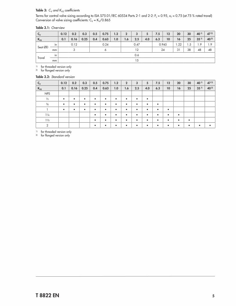
Table 3: CV and KVS coefficientsTerms for control valve sizing according to ISA S75.01/IEC 60534 Parts 2‑1 and 2‑2: FL = 0.95, xT = 0.75 (at 75 % rated travel)Conversion of valve sizing coefficients: CV = KV/0.865
Table 3.1: Overview
CV 0.12 0.2 0.3 0.5 0.75 1.2 2 3 5 7.5 12 20 30 40 1) 47 2)
KVS 0.1 0.16 0.25 0.4 0.63 1.0 1.6 2.5 4.0 6.3 10 16 25 35 1) 40 2)
Seat ØDin 0.12 0.24 0.47 0.945 1.22 1.5 1.9 1.9
mm 3 6 12 24 31 38 48 48
Travelin 0.6
mm 15
1) for threaded version only2) for flanged version only
Table 3.2: Standard version
CV 0.12 0.2 0.3 0.5 0.75 1.2 2 3 5 7.5 12 20 30 40 1) 47 2)
KVS 0.1 0.16 0.25 0.4 0.63 1.0 1.6 2.5 4.0 6.3 10 16 25 35 1) 40 2)
NPS
½ • • • • • • • • •
¾ • • • • • • • • • •
1 • • • • • • • • • • •
1¼ • • • • • • • • •
1½ • • • • • • • • • •
2 • • • • • • • • • • • •
1) for threaded version only2) for flanged version only
6 T 8822 EN
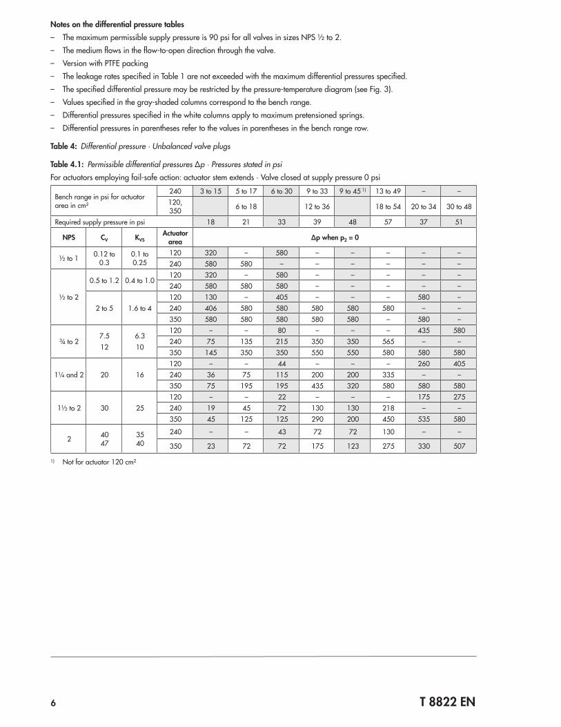
Notes on the differential pressure tables – The maximum permissible supply pressure is 90 psi for all valves in sizes NPS ½ to 2. – The medium flows in the flow‑to‑open direction through the valve. – Version with PTFE packing – The leakage rates specified in Table 1 are not exceeded with the maximum differential pressures specified. – The specified differential pressure may be restricted by the pressure‑temperature diagram (see Fig. 3). – Values specified in the gray‑shaded columns correspond to the bench range. – Differential pressures specified in the white columns apply to maximum pretensioned springs. – Differential pressures in parentheses refer to the values in parentheses in the bench range row.
Table 4: Differential pressure · Unbalanced valve plugs
Table 4.1: Permissible differential pressures Δp · Pressures stated in psiFor actuators employing fail‑safe action: actuator stem extends · Valve closed at supply pressure 0 psi
Bench range in psi for actuator area in cm²
240 3 to 15 5 to 17 6 to 30 9 to 33 9 to 45 1) 13 to 49 – –120, 350 6 to 18 12 to 36 18 to 54 20 to 34 30 to 48
Required supply pressure in psi 18 21 33 39 48 57 37 51
NPS CV KVSActuator
area Δp when p2 = 0
½ to 1 0.12 to 0.3
0.1 to 0.25
120 320 – 580 – – – – –240 580 580 – – – – – –
½ to 2
0.5 to 1.2 0.4 to 1.0120 320 – 580 – – – – –240 580 580 580 – – – – –
2 to 5 1.6 to 4120 130 – 405 – – – 580 –240 406 580 580 580 580 580 – –350 580 580 580 580 580 – 580 –
¾ to 27.512
6.310
120 – – 80 – – – 435 580240 75 135 215 350 350 565 – –350 145 350 350 550 550 580 580 580
1¼ and 2 20 16120 – – 44 – – – 260 405240 36 75 115 200 200 335 – –350 75 195 195 435 320 580 580 580
1½ to 2 30 25120 – – 22 – – – 175 275240 19 45 72 130 130 218 – –350 45 125 125 290 200 450 535 580
2 4047
3540
240 – – 43 72 72 130 – –
350 23 72 72 175 123 275 330 507
1) Not for actuator 120 cm²
T 8822 EN 7
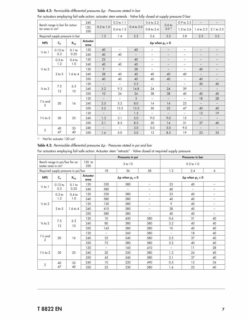
Table 4.2: Permissible differential pressures Δp · Pressures stated in barFor actuators employing fail‑safe action: actuator stem extends · Valve fully closed at supply pressure 0 bar
Bench range in bar for actua‑tor area in cm²
2400.2 to 1.0
0.3 to 1.10.4 to 2.0
0.6 to 2.20.6 to 3.0 1)
0.9 to 3.3 – –120, 350 0.4 to 1.2 0.8 to 2.4 1.2 to 3.6 1.4 to 2.3 2.1 to 3.3
Required supply pressure in bar 1.2 1.4 2.2 2.6 3.2 3.8 2.5 3.5
NPS CV KVSActuator
area Δp when p2 = 0
½ to 1 0.12 to 0.3
0.1 to 0.25
120 40 – 40 – – – – –240 40 40 – – – – – –
½ to 2
0.5 to 1.2
0.4 to 1.0
120 22 – 40 – – – – –240 40 40 40 – – – – –
2 to 5 1.6 to 4120 9 – 28 – – – 40 –240 28 40 40 40 40 40 – –350 40 40 40 40 40 – 40 –
¾ to 27.512
6.310
120 – – 5.5 – – – 30 40240 5.2 9.3 14.8 24 24 39 – –350 10 24 24 38 38 40 40 40
1¼ and 2 20 16
120 – – 3 – – – 18 28240 2.5 5.2 8.0 14 14 23 – –350 5.2 13.5 13.5 30 22 47 40 40
1½ to 2 30 25120 – – 1.5 – – – 12 19240 1.3 3.1 5.0 9.0 9.0 15 – –350 3.1 8.5 8.5 20 14 31 37 40
2 4047
3540
240 – – 3.0 5.0 5.0 9.0 – –350 1.6 5.0 5.0 12 8.5 19 23 35
1) Not for actuator 120 cm²
Table 4.3: Permissible differential pressures Δp · Pressures stated in psi and barFor actuators employing fail‑safe action: Actuator stem “retracts” · Valve closed at required supply pressure
Pressures in psi Pressures in barBench range in psi/bar for ac‑tuator area in cm²
120 to 350 3 to 15 0.2 to 1.0
Required supply pressure in psi/bar 18 36 58 1.2 2.4 4
NPS CV KVSActuator
area Δp when p2 = 0 Δp when p2 = 0
½ to 1 0.12 to 0.3
0.1 to 0.25
120 330 580 – 23 40 –240 580 – – 40 – –
½ to 2
0.3 to 1.2
0.4 to 1.0
120 330 580 – 23 40 –240 580 580 – 40 40 –
2 to 5 1.6 to 4120 130 580 – 9 40 –240 410 580 – 28 40 –350 580 580 – 40 40 –
¾ to 27.512
6.310
120 10 450 580 0.6 31 40240 80 580 580 5.2 40 40350 145 580 580 10 40 40
1¼ and 2 20 16
120 – 260 580 – 18 40240 35 540 580 2.5 37 40350 75 580 580 5.2 40 40
1½ to 2 30 25120 – 160 410 – 11 28240 20 350 580 1.3 24 40350 45 540 580 3.1 37 40
2 4047
3540
240 10 220 490 0.5 15 34350 25 330 580 1.6 23 40

8 T 8822 EN
Table 5: Dimensions for Type 3522 Valve in standard version
Table 5.1: Version with threaded ends
Globe valve Size NPS ½ ¾ 1 1¼ 1½ 2
Length L Class 300in 3.5 3.5 4.31 4.63 5.31 6.66
mm 89 89 109 118 135 169
H1 for actuators
Type 3271, Type 3277 ≤350 cm²
in 9.25 8.75 8.62 8.88
mm 235 222 219 225
Type 3372in 10.6
–mm 269
H2in 1.13 1.13 1.38 1.50 1.68 1.75
mm 28.5 28.5 35 38 43 44.5
Table 5.2: Version with flanges
Globe valve Size NPS ½ ¾ 1 1¼ 1½ 2
Length LClass 150
in 7.3 7.3 7.3–
8.7 10mm 184 184 184 222 254
Class 300in 7.5 7.6 7.8
–9.3 10.5
mm 190 194 197 235 267
H1 for actuators
Type 3271, Type 3277 ≤350 cm²
in 9.25 – 8.62 8.88
mm 235 – 219 225
Type 3372in 10.6
–mm 269
H2in 1.3 1.2 1.4 – 2.1 2.1
mm 33 31 36 – 54.5 54.5
Table 6: Dimensions for actuators
Table 6.1: Dimensions for Type 3271 and Type 3277 Pneumatic Actuators
Actuator areain² 18.6 27.1 37.2 54.3
cm² 120 175 240 350
Diaphragm ØDin 6.6 8.5 9.5 11.0
mm 168 215 240 280
H for Type 3271in 2.7 3.1 2.4 3.2
mm 69 78 62 82
H for Type 3277in 2.8 3.1 2.6 3.2
mm 70 78 65 82
H3 1)in 4.33
mm 110
H5in 3.98
mm 101
Thread M30 x 1.5
a (for Type 3271 Actuator) 1/8 NPT (G 1/8) ¼ NPT (G ¼) ¼ NPT (G ¼) 3/8 NPT (G 3/8)
a2 (for Type 3277 Actuator) – 3/8 NPT (G 3/8)
1) Minimum clearance to remove the actuator
T 8822 EN 9
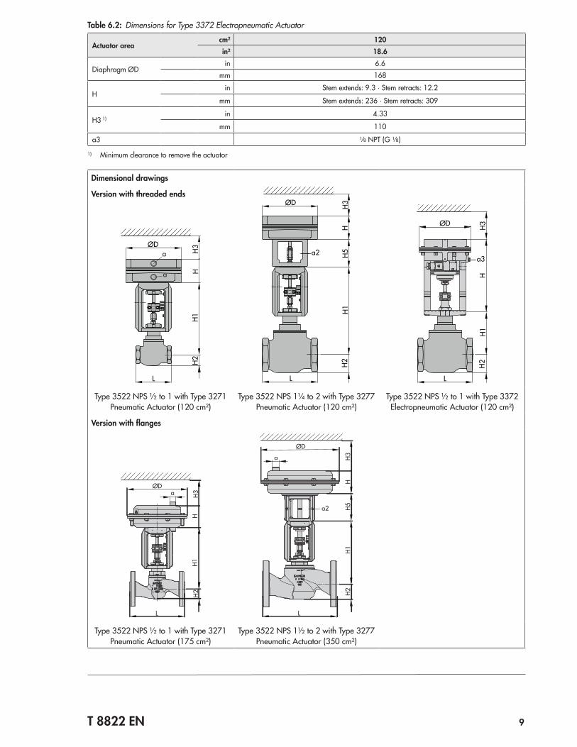
Table 6.2: Dimensions for Type 3372 Electropneumatic Actuator
Actuator areacm² 120in² 18.6
Diaphragm ØDin 6.6
mm 168
Hin Stem extends: 9.3 · Stem retracts: 12.2
mm Stem extends: 236 · Stem retracts: 309
H3 1)in 4.33
mm 110
a3 1/8 NPT (G 1/8)
1) Minimum clearance to remove the actuator
Dimensional drawings
a2
H3H2
ØD
H5H1
L
H ØD H3H
H1H2
L
a3
Version with threaded endsH2
ØD
L
H1H3
H
a
a
Type 3522 NPS ½ to 1 with Type 3271 Pneumatic Actuator (120 cm²)
Type 3522 NPS 1¼ to 2 with Type 3277 Pneumatic Actuator (120 cm²)
Type 3522 NPS ½ to 1 with Type 3372 Electropneumatic Actuator (120 cm²)
Version with flanges
ØD
L
H1H
H2H3a
ØD
L
H1H3
HH2
H5a2
a
Type 3522 NPS ½ to 1 with Type 3271 Pneumatic Actuator (175 cm²)
Type 3522 NPS 1½ to 2 with Type 3277 Pneumatic Actuator (350 cm²)
10 T 8822 EN
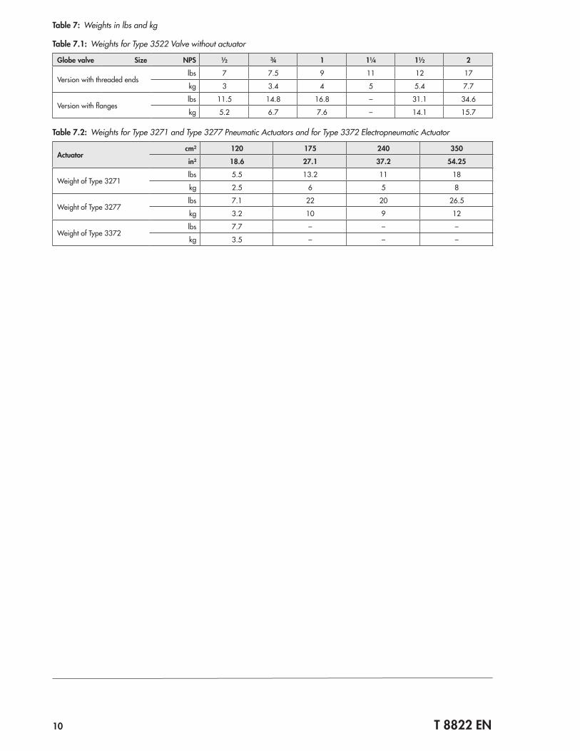
Table 7: Weights in lbs and kg
Table 7.1: Weights for Type 3522 Valve without actuator
Globe valve Size NPS ½ ¾ 1 1¼ 1½ 2
Version with threaded endslbs 7 7.5 9 11 12 17
kg 3 3.4 4 5 5.4 7.7
Version with flangeslbs 11.5 14.8 16.8 – 31.1 34.6
kg 5.2 6.7 7.6 – 14.1 15.7
Table 7.2: Weights for Type 3271 and Type 3277 Pneumatic Actuators and for Type 3372 Electropneumatic Actuator
Actuatorcm² 120 175 240 350
in² 18.6 27.1 37.2 54.25
Weight of Type 3271lbs 5.5 13.2 11 18
kg 2.5 6 5 8
Weight of Type 3277lbs 7.1 22 20 26.5
kg 3.2 10 9 12
Weight of Type 3372lbs 7.7 – – –
kg 3.5 – – –
T 8822 EN 11
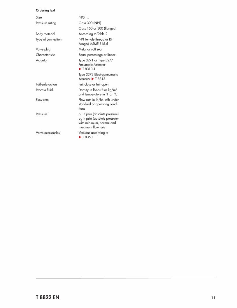
Ordering text
Size NPS …Pressure rating Class 300 (NPT)
Class 150 or 300 (flanged)Body material According to Table 2Type of connection NPT female thread or RF
flanged ASME B16.5Valve plug Metal or soft sealCharacteristic Equal percentage or linearActuator Type 3271 or Type 3277
Pneumatic Actuator u T 8310‑1Type 3372 Electropneumatic Actuator u T 8313
Fail‑safe action Fail‑close or fail‑openProcess fluid Density in lb/cu.ft or kg/m³
and temperature in °F or °CFlow rate Flow rate in lb/hr, scfh under
standard or operating condi‑tions
Pressure p1 in psia (absolute pressure)p2 in psia (absolute pressure)with minimum, normal and maximum flow rate
Valve accessories Versions according to u T 8350

Specifications subject to change without notice
SAMSON AG · MESS- UND REGELTECHNIK Weismüllerstraße 3 · 60314 Frankfurt am Main, Germany Phone: +49 69 4009-0 · Fax: +49 69 4009-1507 [email protected] · www.samson.de T 8822 EN 20
16‑1
2‑19
· En
glish