twisting moment calc
DESCRIPTION
twisting moment calculationsTRANSCRIPT
ShaftsShafts
Vedat TemizAssistant Professor of Machine Design

Introduction• A shaft is a rotating machine element which is used to
transmit power from one place to another. • The power is delivered to the shaft by some tangential force
and the resultant torque (or twisting moment) set up within the shaft permits the power to be transferred to various machines linked up to the shaft In order to transfer themachines linked up to the shaft. In order to transfer the power from one shaft to another, the various members such as pulleys, gears etc., are mounted on it. These members p y , g ,along with the forces exerted upon them causes the shaft to bending.
• In other words, we may say that a shaft is used for the transmission of torque and bending moment. The various
b t d th h ft b f kmembers are mounted on the shaft by means of keys or splines.
Introduction• Notes• The shafts are usually cylindrical, but may be square or cross‐
shaped in section. They are solid in cross‐section but sometimes hollow shafts are also used.
• An axle, though similar in shape to the shaft, is a stationary hi l t d i d f th t i i f b dimachine element and is used for the transmission of bending
moment only. It simply acts as a support for some rotating body such as hoisting drum a car wheel or a rope sheavebody such as hoisting drum, a car wheel or a rope sheave.
• A spindle is a short shaft that imparts motion either to a cutting tool (e.g. drill press spindles) or to a work piece (e.g. g ( g p p ) p ( glathe spindles)
Material Used for Shafts
• The material used for shafts should have the following• The material used for shafts should have the following properties :
• 1. It should have high strength.• 2 It should have good machinability• 2. It should have good machinability.• 3. It should have low notch sensitivity factor.• 4 It should have good heat treatment properties• 4. It should have good heat treatment properties.• 5. It should have high wear resistant properties.
Manufacturing of Shaftsg
• Shafts are generally manufactured by hot rolling and• Shafts are generally manufactured by hot rolling and finished to size by cold drawing or turning and grindinggrinding.
• The cold rolled shafts are stronger than hot rolled h f b i h hi h id lshafts but with higher residual stresses.
• The residual stresses may cause distortion of the shaft when it is machined, especially when slots or keyways are cut.
• Shafts of larger diameter are usually forged and turned to size in a lathe.
Types of Shaftsyp
• 1 Transmission shafts These shafts transmit power between• 1. Transmission shafts. These shafts transmit power between the source and the machines absorbing power. The counter shafts, line shafts, over head shafts and all factory shafts are , , ytransmission shafts. Since these shafts carry machine parts such as pulleys, gears etc., therefore they are subjected to bending in addition to twisting.
• 2. Machine shafts. These shafts form an integral part of the machine itself. The crank shaft is an example of machine shaft.

Standard Sizes of Transmission Shafts
Th t d d i f t i i h ft• The standard sizes of transmission shafts are :• 25 mm to 60 mm with 5 mm steps; 60 mm to 110 mm with 10 mm steps ; 110 mm to 140 mm with 15 mm steps ; and 140 mm to 500mm with 15 mm steps ; and 140 mm to 500 mm with 20 mm steps.h d d l h f h h f 6• The standard length of the shafts are 5 m, 6 m and 7 m.
Stresses in Shafts
• The following stresses are induced in the shafts :• The following stresses are induced in the shafts :• 1. Shear stresses due to the transmission of torque(i d i l l d)(i.e. due to torsional load).
• 2. Bending stresses (tensile or compressive) due to the forces acting upon machine elements like gears, pulleys etc. as well as due to the weight of the shaft itself.
• 3. Stresses due to combined torsional and bending gloads
Maximum Permissible Working Stresses for Transmission Shaftsfor Transmission Shafts
• According to American Society of Mechanical Engineers (ASME) code for the design of transmissionEngineers (ASME) code for the design of transmission shafts, the maximum permissible working stresses in tension or compression may be taken astension or compression may be taken as
• (a) 112 MPa for shafts without allowance for keywayskeyways.
• (b) 84 MPa for shafts with allowance for keyways.
Maximum Permissible Working Stresses for Transmission Shaftsfor Transmission Shafts
• For shafts purchased under definite physical• For shafts purchased under definite physical specifications, the permissible tensile stress (σt) may be taken as 60 per cent of the elastic limit in tensionbe taken as 60 per cent of the elastic limit in tension (σel), but not more than 36 per cent of the ultimate tensile strength (σ ) In other words the permissibletensile strength (σu). In other words, the permissible tensile stress,
0 6 0 36 hi h i l• σt = 0.6 σel or 0.36 σu, whichever is less.
Maximum Permissible Working Stresses for Transmission Shaftsfor Transmission Shafts
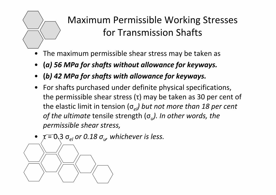
• The maximum permissible shear stress may be taken as• The maximum permissible shear stress may be taken as• (a) 56 MPa for shafts without allowance for keyways.• (b) 42 MPa for shafts with allowance for keyways• (b) 42 MPa for shafts with allowance for keyways.• For shafts purchased under definite physical specifications,
the permissible shear stress (τ) may be taken as 30 per cent ofthe permissible shear stress (τ) may be taken as 30 per cent of the elastic limit in tension (σel) but not more than 18 per cent of the ultimate tensile strength (σu). In other words, the upermissible shear stress,
• τ = 0.3 σel or 0.18 σu, whichever is less.

Design of Shaftsg
• The shafts may be designed on the basis of• The shafts may be designed on the basis of• 1. Strength, and 2. Rigidity and stiffness.• In designing shafts on the basis of strength the following• In designing shafts on the basis of strength, the following
cases may be considered :• (a) Shafts subjected to twisting moment or torque only• (a) Shafts subjected to twisting moment or torque only,• (b) Shafts subjected to bending moment only,• (c) Shafts subjected to combined twisting and bending• (c) Shafts subjected to combined twisting and bending
moments, and• (d) Shafts subjected to axial loads in addition to combined(d) Shafts subjected to axial loads in addition to combined
torsional and bending loads.
Shafts Subjected to Twisting M t O lMoment Only
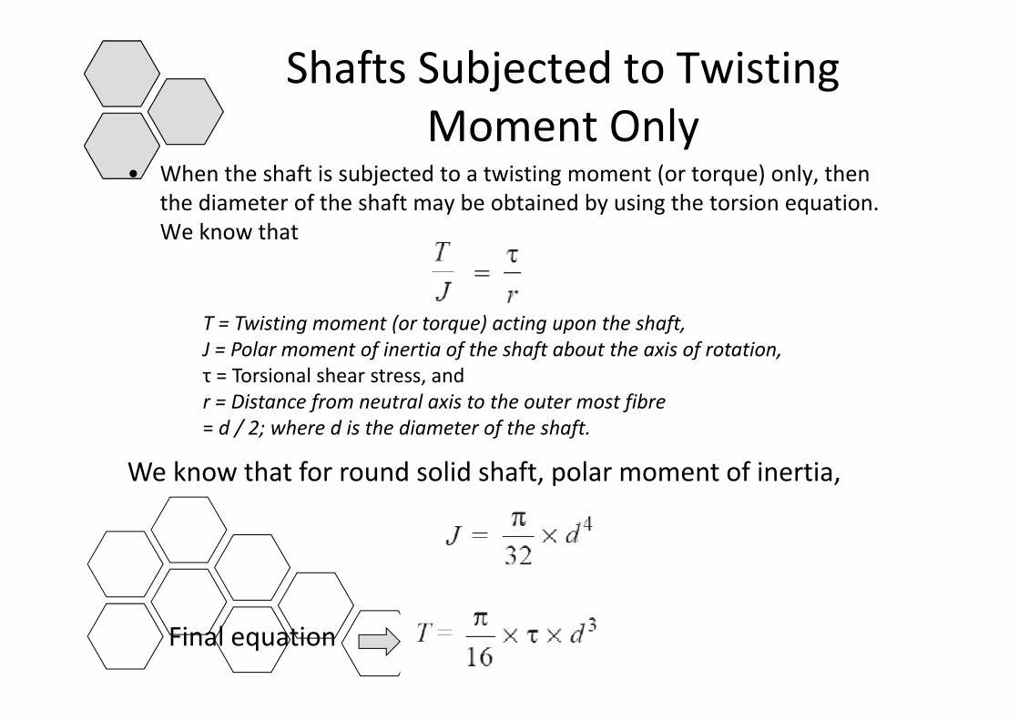
• When the shaft is subjected to a twisting moment (or torque) only, then th di t f th h ft b bt i d b i th t i tithe diameter of the shaft may be obtained by using the torsion equation. We know that
T = Twisting moment (or torque) acting upon the shaft,J = Polar moment of inertia of the shaft about the axis of rotation,τ = Torsional shear stress, andr = Distance from neutral axis to the outer most fibre= d / 2; where d is the diameter of the shaft.
We know that for round solid shaft, polar moment of inertia,
Final equation
Shafts Subjected to Twisting M t O lMoment Only
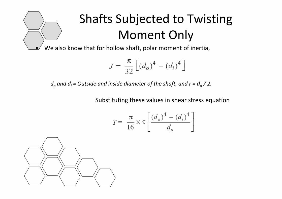
• We also know that for hollow shaft, polar moment of inertia,
do and di = Outside and inside diameter of the shaft, and r = do / 2.
Substituting these values in shear stress equationSubstituting these values in shear stress equation
Shafts Subjected to Bending M t O l (A l )Moment Only (Axles)
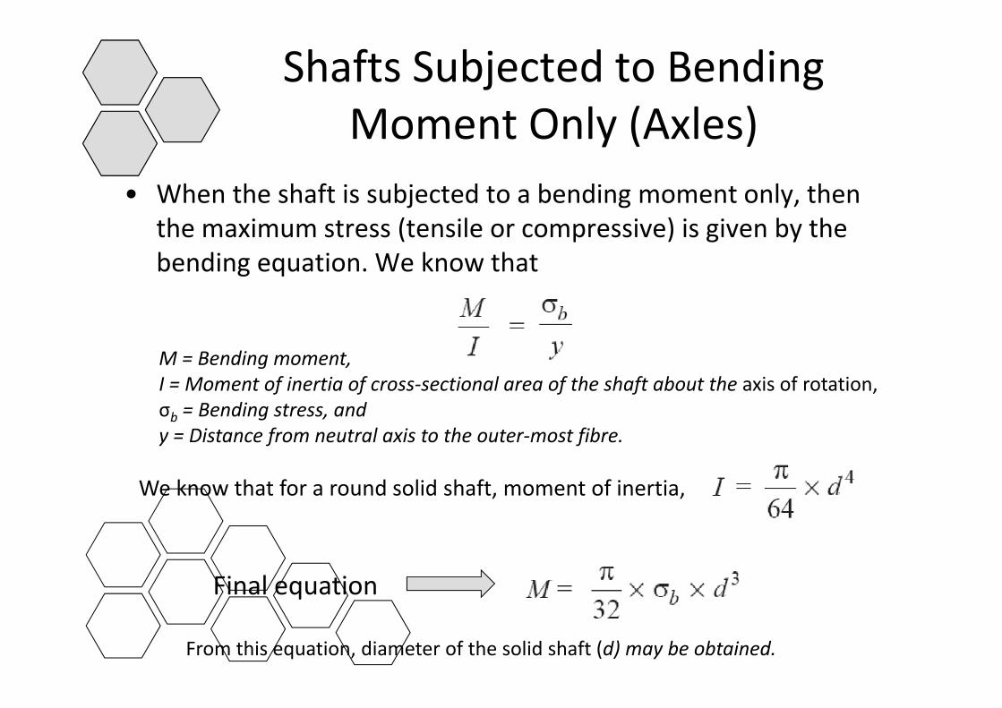
• When the shaft is subjected to a bending moment only then• When the shaft is subjected to a bending moment only, then the maximum stress (tensile or compressive) is given by the bending equation. We know thatg q
M B di tM = Bending moment,I = Moment of inertia of cross‐sectional area of the shaft about the axis of rotation,σb = Bending stress, andy = Distance from neutral axis to the outer most fibrey = Distance from neutral axis to the outer‐most fibre.
We know that for a round solid shaft, moment of inertia,
Final equationq
From this equation, diameter of the solid shaft (d) may be obtained.
Shafts Subjected to Combined Twisting Moment and Bending MomentMoment and Bending Moment
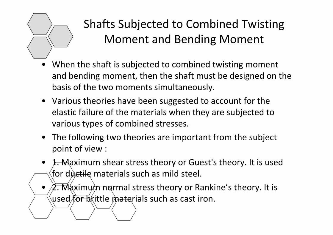
• When the shaft is subjected to combined twisting moment• When the shaft is subjected to combined twisting moment and bending moment, then the shaft must be designed on the basis of the two moments simultaneously. y
• Various theories have been suggested to account for the elastic failure of the materials when they are subjected to various types of combined stresses.
• The following two theories are important from the subject point of view :
• 1. Maximum shear stress theory or Guest's theory. It is used f d il i l h ild lfor ductile materials such as mild steel.
• 2. Maximum normal stress theory or Rankine’s theory. It is used for brittle materials such as cast ironused for brittle materials such as cast iron.
Shafts Subjected to Combined Twisting Moment and Bending MomentMoment and Bending Moment
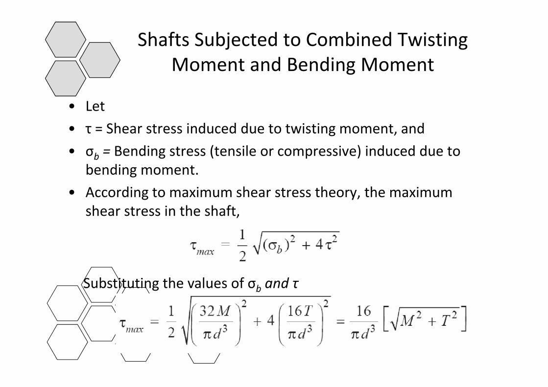
• Let• Let • τ = Shear stress induced due to twisting moment, and• σ = Bending stress (tensile or compressive) induced due to• σb = Bending stress (tensile or compressive) induced due to
bending moment.• According to maximum shear stress theory the maximum• According to maximum shear stress theory, the maximum
shear stress in the shaft,
Substituting the values of σ and τSubstituting the values of σb and τ

Shafts Subjected to Combined Twisting Moment and Bending MomentMoment and Bending Moment
• The expression• The expression
is known as equivalent twisting moment and is denoted by Te. The equivalent twisting moment may be defined as that twistingThe equivalent twisting moment may be defined as that twisting moment, which when acting alone, produces the same shear stress (τ) as the actual twisting moment. By limiting the maximum ( ) g y gshear stress (τmax) equal to the allowable shear stress (τ) for the material, the first equation may be written as
From this expression, diameter of the shaft ( d ) may be evaluated.
Shafts Subjected to Combined Twisting Moment and Bending MomentMoment and Bending Moment
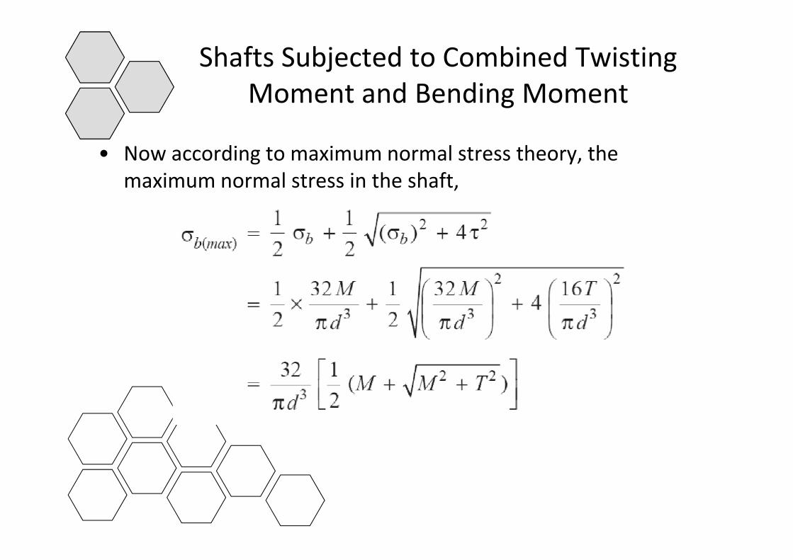
• Now according to maximum normal stress theory the• Now according to maximum normal stress theory, the maximum normal stress in the shaft,
Shafts Subjected to Combined Twisting Moment and Bending MomentMoment and Bending Moment
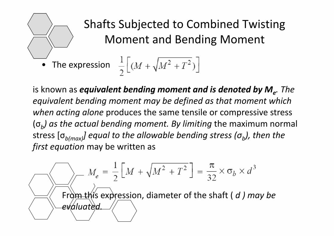
• The expression• The expression
is known as equivalent bending moment and is denoted by M Theis known as equivalent bending moment and is denoted by Me. The equivalent bending moment may be defined as that moment which when acting alone produces the same tensile or compressive stress (σb) as the actual bending moment. By limiting the maximum normal stress [σb(max)] equal to the allowable bending stress (σb), then the fi t ti b ittfirst equation may be written as
From this expression, diameter of the shaft ( d ) may be p , ( ) yevaluated.
Shafts Subjected to Fluctuating Loadsj g• In the previous calculations, we have assumed that the shaft is
subjected to constant torque and bending momentsubjected to constant torque and bending moment. • But in actual practice, the shafts are subjected to fluctuating
torque and bending moments. q g• In order to design such shafts like line shafts and counter
shafts, the combined shock and fatigue factors must be taken into account for the computed twisting moment (T ) and bending moment (M ).
• Thus for a shaft subjected to combined bending and torsion, the equivalent twisting moment
Shafts Subjected to Fluctuating Loadsj g
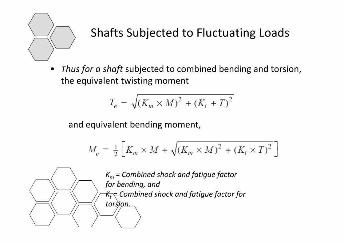
Th f h ft bj t d t bi d b di d t i• Thus for a shaft subjected to combined bending and torsion, the equivalent twisting moment
d i l b diand equivalent bending moment,
Km = Combined shock and fatigue factorKm Combined shock and fatigue factor for bending, andKt = Combined shock and fatigue factor for torsiontorsion.
Shafts Subjected to Fluctuating Loadsj g
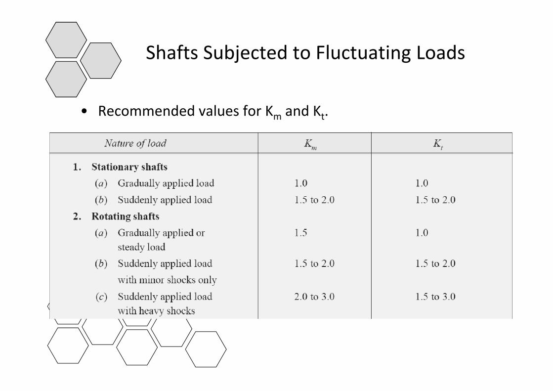
R d d l f K d K• Recommended values for Km and Kt.
Design of Shafts on the basis of Rigidityg g y
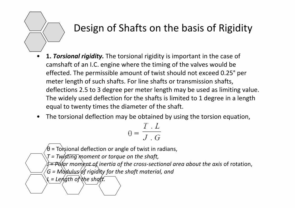
• 1 Torsional rigidity The torsional rigidity is important in the case of• 1. Torsional rigidity. The torsional rigidity is important in the case of camshaft of an I.C. engine where the timing of the valves would be effected. The permissible amount of twist should not exceed 0.25° per meter length of such shafts For line shafts or transmission shaftsmeter length of such shafts. For line shafts or transmission shafts, deflections 2.5 to 3 degree per meter length may be used as limiting value. The widely used deflection for the shafts is limited to 1 degree in a length
l h d f h h fequal to twenty times the diameter of the shaft.• The torsional deflection may be obtained by using the torsion equation,
θ = Torsional deflection or angle of twist in radians,g ,T = Twisting moment or torque on the shaft,J = Polar moment of inertia of the cross‐sectional area about the axis of rotation,G = Modulus of rigidity for the shaft material, andL = Length of the shaft.
Design of Shafts on the basis of Rigidityg g y
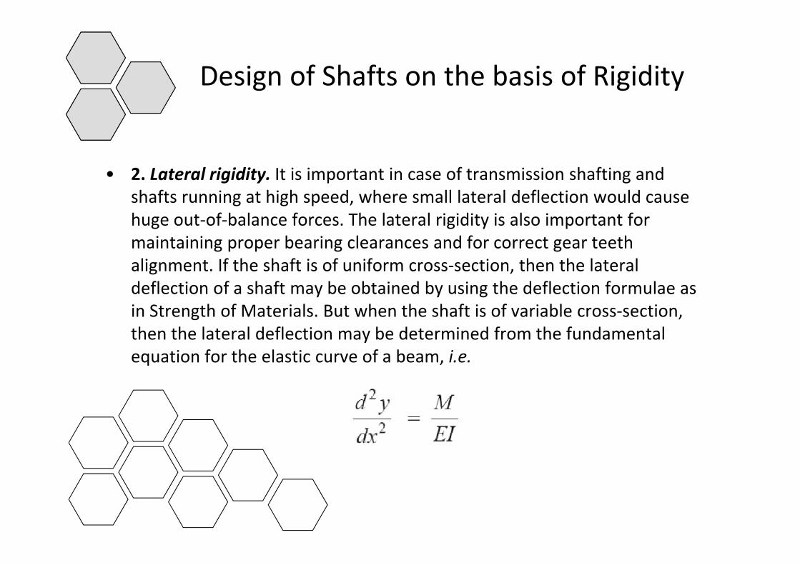
• 2. Lateral rigidity. It is important in case of transmission shafting and shafts running at high speed, where small lateral deflection would cause huge out of balance forces The lateral rigidity is also important forhuge out‐of‐balance forces. The lateral rigidity is also important for maintaining proper bearing clearances and for correct gear teeth alignment. If the shaft is of uniform cross‐section, then the lateral d fl i f h f b b i d b i h d fl i f ldeflection of a shaft may be obtained by using the deflection formulae as in Strength of Materials. But when the shaft is of variable cross‐section, then the lateral deflection may be determined from the fundamental equation for the elastic curve of a beam, i.e.