tutorial - roland care service &...
TRANSCRIPT
Tutorial
Thank you very much for purchasing the Roland printer.
• To ensure correct and safe usage with a full understanding ofthis product’s performance, please be sure to read through thismanual completely and store it in a safe location.
• Unauthorized copying or transferal, in whole or in part, of thismanual is prohibited.
• The contents of this operation manual and the specifications ofthis product are subject to change without notice.
• The operation manual and the product have been prepared andtested as much as possible. If you find any misprint or error,please inform us.
• Roland DG Corp. assumes no responsibility for any direct orindirect loss or damage which may occur through use of thisproduct, regardless of any failure to perform on the part of thisproduct.
• Roland DG Corp. assumes no responsibility for any direct orindirect loss or damage which may occur with respect to anyarticle made using this product.
Table of Contents
About Serial-number Registration……………………………………... 4 Overview………………………………….…………………………………………… 4 Work Process………………………………………………………………………. 5 Basics…………………………………………………………………………………… 6
System Requirements…………………………………………………………… 6 File I/O Specifications …………………………………………………………… 7 GUI ………………………………………………………………………………….. 8 Right Mouse Button Menu ……………………………………………………… 9 Viewing & Displaying ………………………………………………………….. 11 Trackball & Transformation ……………………………………………………13 Selecting & Deleting ……………………………………………………………15 Measure …………………………………………………………………………… 17 Undo ……………………………………………………………………………… 18 Preferences ………………………………………………………………………19 Hot Keys ………………………………………………………………………… 21 Using On-line Help ……………………………………………………………... 22
Scan Workbench ………………………………………………………………23
Select and Delete …………………………………………………………………23 Shell Trackball ……………………………………………………………………26 Registration of 2 shells …………………………………………………………27 Global Registration ……………………………………………………………... 28 Merge Shells …………………………………………………………………….. 30
Page 2 of 50 Pixform2001 Tutorial
Polygon Workbench………………………………………………………….. 33 Clean……………………………………………………………………………….. 34 Fill Holes ………………………………………………………………………….. 35 Decimate ………………………………………………………………………….. 38 Smooth…………………………………………………………………………….. 39 Subdivide ……………………………………………………………………….. 42 Remesh …………………………………………………………………………. 43 Transform ……………………………………………………………………….. 44
Surface Workbench ………………………………………………………….. 45
Auto Surfacing …………………………………………………………………. 45
Glossary ……………………………………………………………………………. 48
Windows® is a registered trademarks of Microsoft® Corporation in the United States and/or other countries.
Pixform™ is a trademark of Roland DG corporation.
Other company names and product names are trademarks or registered trademarks of their respective holders.
Copyright©2001-2003 Roland DG corporation, INUS technology, Inc. All right reserved.
http://www.rolanddg.com
Pixform2001 Tutorial Page 3 of 50
About Serial-number Registration Before you can use Pixform, you need to register the serial number. After installing and setting up Pixform, follow the steps below to register it. Please note that unless you register the serial number, files cannot be saved or exported. You can find the serial number on the label affixed to the CD-ROM case.
1. Start Pixform. 2. Go into the [Help] menu and click [Register Pixform]. 3. Enter the user name you want to use, type in the serial number, then click
[OK]. 4. Restart Pixform.
Overview Pixform consists of three workbenches: Scan, Polygon, and Surface.
Basics : • Various data formats support (IGES, VRML, DXF, STL, ICF) • Unlimited undo operation • Working view volume management • Various selection tools • Layer management • Complete texture information support • 3D polygon data compression (ICF file format) • Export color 3D content for Web-based applications
Scan Workbench :
• Align/register data with common polygon in two different coordinate frames • Merge multiple polygonal models with high accuracy
Polygon Workbench :
• Automatic detection and cleaning of bad polygon meshes • Quality enhancement smoothing and real-time smoothing • Curvature-based decimation • Automatic global re-meshing for dramatic polygon quality enhancement • Curvature-based hole filling
Surface Workbench :
• Automatic NURBS surface generation from polygon model • High accuracy polygon to NURBS surface conversion • G0/G1/C1 matching with multiple-adjacent surfaces • Interactive accuracy verification
Page 4 of 50 Pixform2001 Tutorial
• Seamless integration with other CAD system
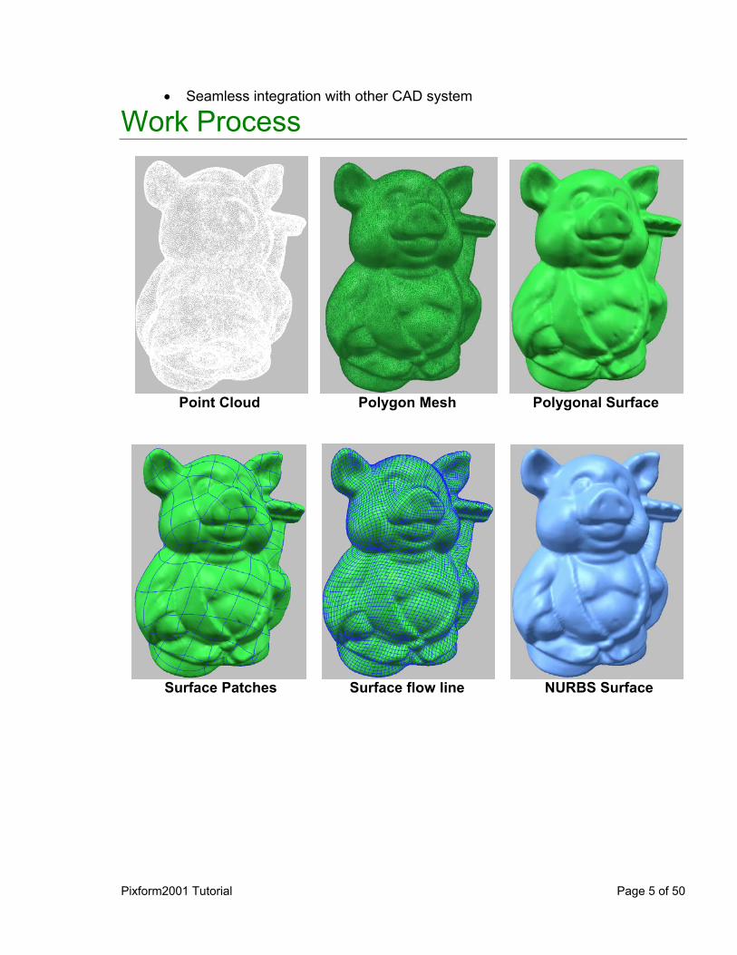
Work Process
Point Cloud Polygon Mesh Polygonal Surface
Surface Patches Surface flow line NURBS Surface
Pixform2001 Tutorial Page 5 of 50
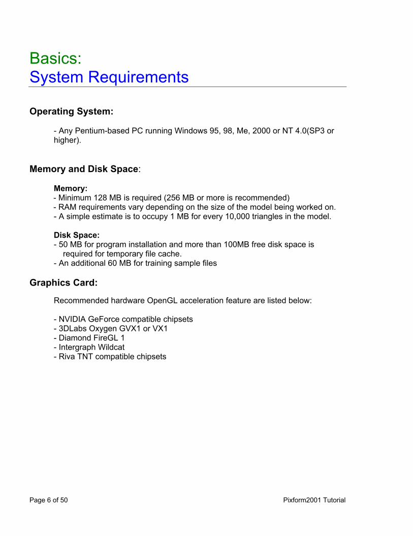
Basics: System Requirements Operating System:
- Any Pentium-based PC running Windows 95, 98, Me, 2000 or NT 4.0(SP3 or higher).
Memory and Disk Space:
Memory: - Minimum 128 MB is required (256 MB or more is recommended) - RAM requirements vary depending on the size of the model being worked on. - A simple estimate is to occupy 1 MB for every 10,000 triangles in the model. Disk Space: - 50 MB for program installation and more than 100MB free disk space is
required for temporary file cache. - An additional 60 MB for training sample files
Graphics Card:
Recommended hardware OpenGL acceleration feature are listed below: - NVIDIA GeForce compatible chipsets - 3DLabs Oxygen GVX1 or VX1 - Diamond FireGL 1 - Intergraph Wildcat - Riva TNT compatible chipsets
Page 6 of 50 Pixform2001 Tutorial
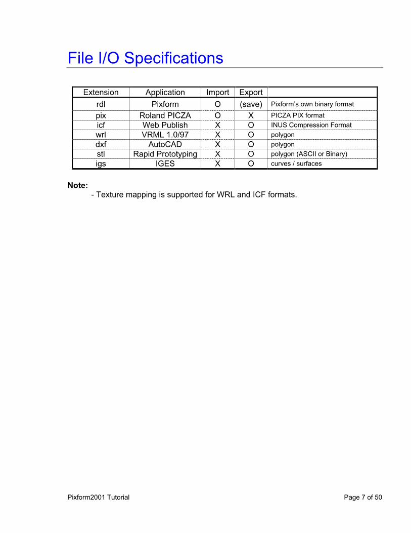
File I/O Specifications
Extension Application Import Export rdl Pixform O (save) Pixform’s own binary format
pix Roland PICZA O X PICZA PIX format icf Web Publish X O INUS Compression Format wrl VRML 1.0/97 X O polygon dxf AutoCAD X O polygon stl Rapid Prototyping X O polygon (ASCII or Binary) igs IGES X O curves / surfaces
Note:
- Texture mapping is supported for WRL and ICF formats.
Pixform2001 Tutorial Page 7 of 50
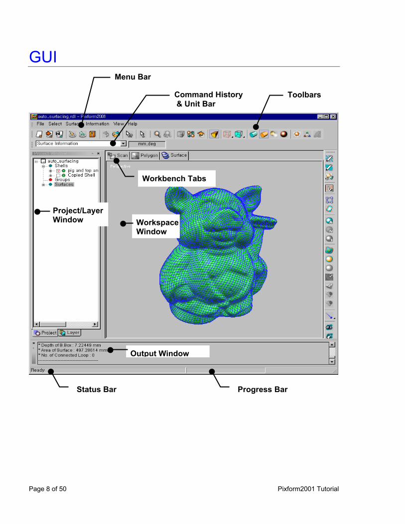
GUI
Menu Bar
Command History & Unit Bar
Toolbars
Workbench Tabs
Project/LayerWindow Workspace
Window
Output Window
Status Bar Progress Bar
Page 8 of 50 Pixform2001 Tutorial

Right Mouse Button Menu In addition to the menu bar, there are menus that appear when you click the right mouse button (RMB). On Toolbar:
You can show or hide toolbars as selecting them after clicking RMB on menu bar or toolbars (as shown right). Also, you can customize GUI and keyboard.
On Workspace Window:
Last command can be repeated and also use display menu and selection menu frequently used by clicking RMB on workspace window (as shown below).
On Project/Layer Window: You can use quick menus for changing property of entities and exporting specific entities as clicking RMB on Project/Layer Window (as shown below).
Pixform 2001 Tutorial Page 9 of 50
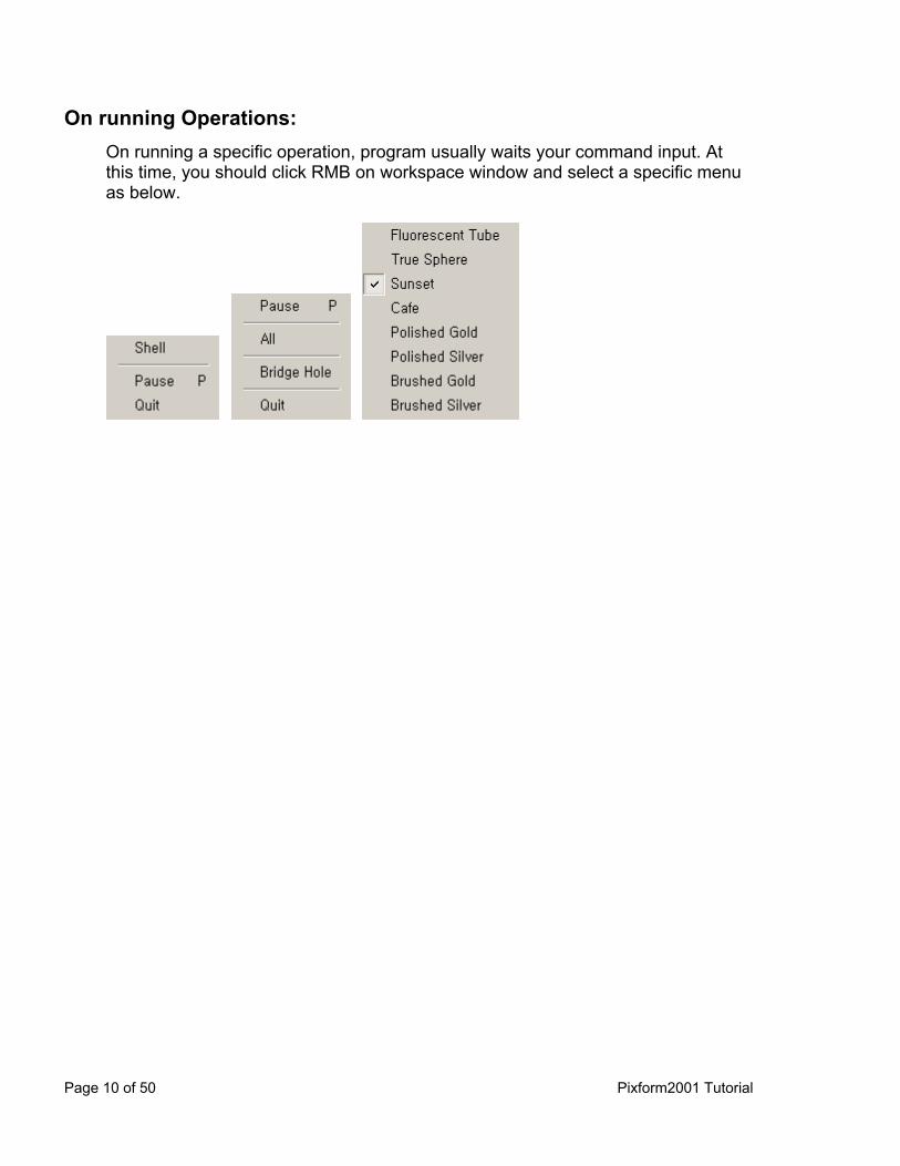
On running Operations: On running a specific operation, program usually waits your command input. At this time, you should click RMB on workspace window and select a specific menu as below.
Page 10 of 50 Pixform2001 Tutorial
Viewing & Displaying
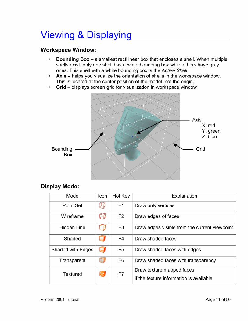
Workspace Window: Bounding Box – a smallest rectilinear box that encloses a shell. When multiple
shells exist, only one shell has a white bounding box while others have gray ones. This shell with a white bounding box is the Active Shell.
Axis – helps you visualize the orientation of shells in the workspace window. This is located at the center position of the model, not the origin.
Grid – displays screen grid for visualization in workspace window
Axis X: red Y: green Z: blue
Grid BoundingBox
Display Mode: Mode Icon Hot Key Explanation
Point Set F1 Draw only vertices
Wireframe F2 Draw edges of faces
Hidden Line F3 Draw edges visible from the current viewpoint
Shaded F4 Draw shaded faces
Shaded with Edges F5 Draw shaded faces with edges
Transparent F6 Draw shaded faces with transparency
Textured F7 Draw texture mapped faces
if the texture information is available
Pixform 2001 Tutorial Page 11 of 50
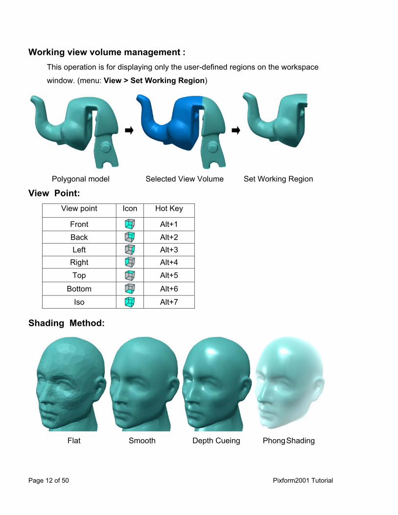
Working view volume management : This operation is for displaying only the user-defined regions on the workspace
window. (menu: View > Set Working Region)
Polygonal model Selected View Volume Set Working Region
View Point: View point Icon Hot Key
Front Alt+1
Back Alt+2 Left Alt+3
Right Alt+4
Top Alt+5
Bottom Alt+6
Iso Alt+7
Shading Method:
Flat Smooth Depth Cueing Phong Shading
Page 12 of 50 Pixform2001 Tutorial
Trackball & Transformation
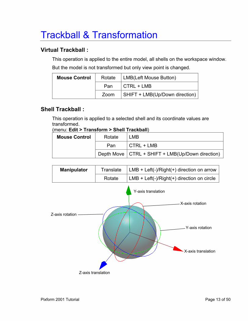
Virtual Trackball : This operation is applied to the entire model, all shells on the workspace window.
But the model is not transformed but only view point is changed.
Mouse Control Rotate LMB(Left Mouse Button)
Pan CTRL + LMB
Zoom SHIFT + LMB(Up/Down direction)
Shell Trackball : This operation is applied to a selected shell and its coordinate values are transformed. (menu: Edit > Transform > Shell Trackball)
Mouse Control Rotate LMB
Pan CTRL + LMB
Depth Move CTRL + SHIFT + LMB(Up/Down direction)
Manipulator Translate LMB + Left(-)/Right(+) direction on arrow
Rotate LMB + Left(-)/Right(+) direction on circle
Y-axis translation
X-axis rotation
Z-axis rotation
Y-axis rotation
X-axis translation
Z-axis translation
Pixform 2001 Tutorial Page 13 of 50
Shell/Model Transformation : (menu: Edit > Transform > Shell or Model) Rotate – rotate a shell/model as given angle around specific axis Translate – translate a shell/model as given distance in the x, y, or z direction Scale – increase or decrease the actual size of a shell/model
Page 14 of 50 Pixform2001 Tutorial
Selecting & Deleting
Commands: Select Entities – Vertex, Face, Shell, Surface Select All / None / Inverse – Vertex, Face Select Custom Region – Face Select Flood Fill – Face Select Boundary – Vertex, Face Select Enlarge Depth/Feature – Face Select Visible / Through – Face Select Mode – Line, Rectangle, Circle, Freehand, Paint Brush
Selection Method: Picking – single selection,
Freehand – Vertex, Face,
Paint Brush – Vertex, Face, (NOTE: By Paint Brush, visible vertices or faces only are selected, if model has polygonal mesh)
Dragging – Multiple Selection, Vertex, Face, Shell, Surface,
NOTE: To selectively unselect entities, press the Ctrl key while selecting entities from the current highlighted selection.
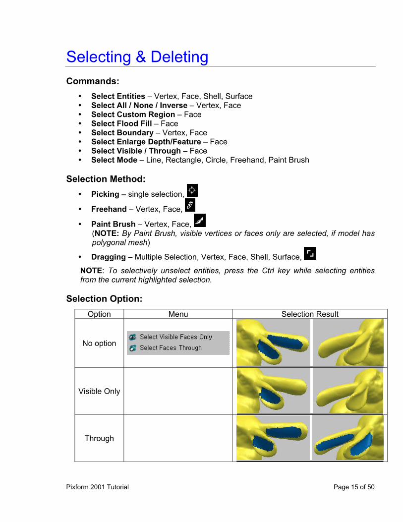
Selection Option:
Option Menu Selection Result
No option
Visible Only
Through
Pixform 2001 Tutorial Page 15 of 50
Deleting: Single Entity – (i) Vertex, Face, Shell: Edit > Delete
(ii) Surface: [Menu] > Delete Multiple Entity – Vertices, Faces, or Surfaces can be deleted by performing
each Delete command as soon as selecting each entities Selecting & Deleting on Project Window: Single Entity Selection – pick each node with LMB Single Entity Deletion – pick each node with RMB, and select Delete on RMB
menu. Multiple Entity Deletion – pick an upper rank node with RMB, and select Delete
All on RMB menu. Shown Entity Deletion – pick an upper rank node with RMB, and select Delete
Shown Entities on RMB menu.
Page 16 of 50 Pixform2001 Tutorial
Measure
You can measure the distance, radius and angle. Also, there are useful functions for three-dimensional quantitative measurements such as cross section viewing, curvature plot, etc. You can also get the model information such as the object size, area, volume, and numbers of entities. Distance: Point / Point along line Point / Point along surface Perimeter
Radius: Circle Sphere Rounded Area Radius
Angle: 3 Points 2 Vectors
Cross Section: Perimeter Area Centroid Distance and displacement between points
Deviation: Shell / Shell and Surface / Shell
Curvature: Mean, Gaussian, Maximum and Minimum
NOTE: You can convert the deviation or curvature color maps to the vertex color of
objects.
Pixform 2001 Tutorial Page 17 of 50
Undo
You can use the Undo command to removes the effects of the last operation performed.
To perform the Undo command, a saving space called command stack is required. The Size of the command stack means the maximum number of recent commands undoable. There is no limit to the size of the command stack in Pixform. You can record and undo commands as many times as the memory permits. But, the larger the size of the command stack, the weaker the performance. Therefore, setting a practically appropriate command stack size is important. To set the size of the command stack select File > Preferences menu, and change the value of Undo depth item in the General Options tab.
Undo depth configures the size of the command stack to return an object to the state it was in before the last action.
The Undo command, disabled by default, can be enabled or disabled alternately by clicking icon in the standard toolbar or by clicking Edit > Enable Undo menu in toggle type. Only when Undo is enabled, recently executed operations are recorded. To
undo an operation, click Edit > Undo in the menu bar or icon in the standard toolbar or push the hot key, Ctrl+Z.
The Undo command is available for most operations except for the follows: -. Selection -. Viewing -. Measuring -. Inquiring Information
Page 18 of 50 Pixform2001 Tutorial
Preferences You can change a variety of Pixform’s default settings to customize the application and accommodate your personal work style and needs. All of the options can be accessed by clicking File > Preferences menu. General Options: Undo depth – configures the size of the command stack to return an object to
the state it was in before the last action. For enabling or disabling this option, you should click Edit > Enable Undo menu in toggle type.
Auto save – makes the current model save automatically at regular intervals in minute. This option can be enabled or disabled by checking or un-checking the small box in front of this item.
Cache Directory – is where the automatically saved file(RDLAutoSave1.rdl) and all the temporary files locate.
Number of recent RDL files – is the number of recently worked file list shown beneath File > Recent Files.
External Data Unit – is the unit of external model imported through File > Import command, and used as the basic unit of numerical input while executing commands such as Transform, Delete Spikes, etc.
Internal Measure Unit – is the unit used internally within Pixform, and used as the basic unit for showing information while executing commands such as Measure, Information, etc.
Display Options: Polygon draw – Offset factor and Offset unit are parameters used when
displaying shells with Shaded with Edges or Hidden Line rendering mode. In case edges do not look clearly, up or down the values of these parameters. The phenomenon arises from incompatible graphic driver.
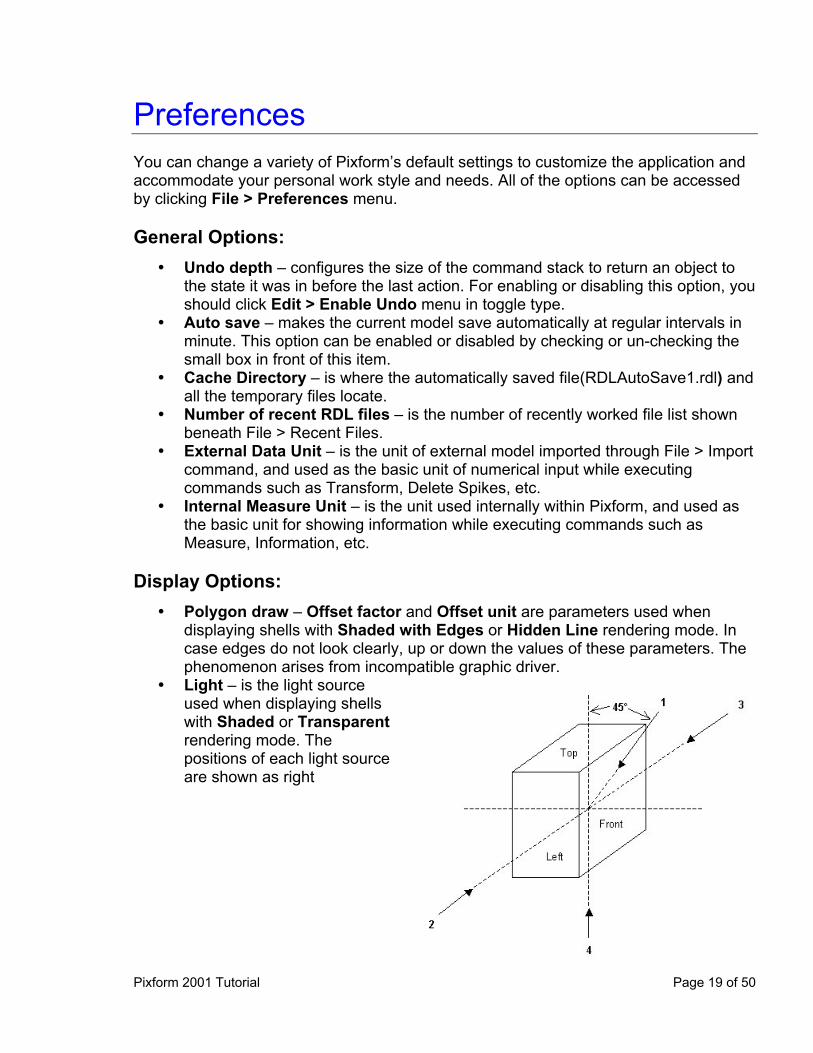
Light – is the light source used when displaying shells with Shaded or Transparent rendering mode. The positions of each light source are shown as right
Pixform 2001 Tutorial Page 19 of 50

Dynamic Draw – is used to increase the performance of virtual trackball Show at launching – decides whether or not to show the bounding box, axis,
and grid on the screen when a new workspace window is opened. Select –is used to select only faces which are visible on the screen. Increase the
Buffer Size to select very many faces. Picking – configures the size of the rectangle in the pixel unit, and it affects the
accuracy of picking result. Turn on the Vertex snap option to pick a vertex when you pick a position close to it.
Gradient Background – sets the default background color of Workspace window to gradient gray color.
2 Side Shading – is used to render both sides of polygons
Page 20 of 50 Pixform2001 Tutorial
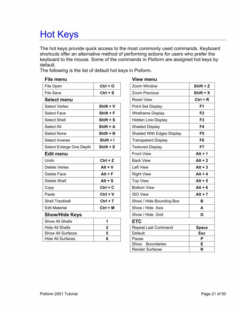
Hot Keys The hot keys provide quick access to the most commonly used commands. Keyboard shortcuts offer an alternative method of performing actions for users who prefer the keyboard to the mouse. Some of the commands in Pixform are assigned hot keys by default. The following is the list of default hot keys in Pixform.
File menu View menu File Open Ctrl + O Zoom Window Shift + Z
File Save Ctrl + S Zoom Previous Shift + X
Select menu Reset View Ctrl + R
Select Vertex Shift + V Point Set Display F1
Select Face Shift + F Wireframe Display F2
Select Shell Shift + S Hidden Line Display F3
Select All Shift + A Shaded Display F4
Select None Shift + N Shaded With Edges Display F5
Select Inverse Shift + I Transparent Display F6
Select Enlarge One Depth Shift + E Textured Display F7
Edit menu Front View Alt + 1
Undo Ctrl + Z Back View Alt + 2
Delete Vertex Alt + V Left View Alt + 3
Delete Face Alt + F Right View Alt + 4
Delete Shell Alt + S Top View Alt + 5
Copy Ctrl + C Bottom View Alt + 6
Paste Ctrl + V ISO View Alt + 7
Shell Trackball Ctrl + T Show / Hide Bounding Box B
Edit Material Ctrl + M Show / Hide Axis A
Show/Hide Keys Show / Hide Grid G
Show All Shells 1 ETC Hide All Shells 2 Repeat Last Command Space Show All Surfaces 5 Default Esc Hide All Surfaces 6 Pause P Show Boundaries E Render Surfaces R
Pixform 2001 Tutorial Page 21 of 50
Using On-line Help There are two ways you can access on-line help. You can open the Help window and search for information on a specific topic, or you can use context-sensitive help.
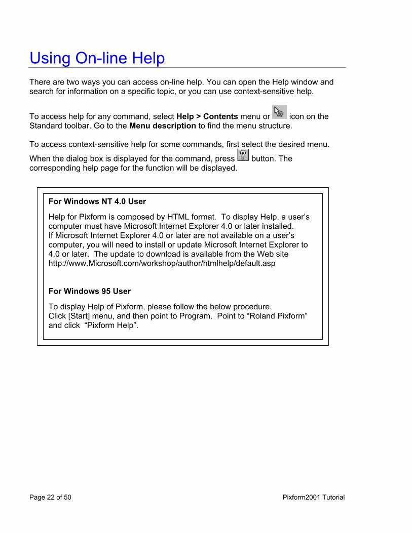
To access help for any command, select Help > Contents menu or icon on the Standard toolbar. Go to the Menu description to find the menu structure. To access context-sensitive help for some commands, first select the desired menu.
When the dialog box is displayed for the command, press button. The corresponding help page for the function will be displayed.
For Windows NT 4.0 User Help for Pixform is composed by HTML format. To display Help, a user’s computer must have Microsoft Internet Explorer 4.0 or later installed. If Microsoft Internet Explorer 4.0 or later are not available on a user’s computer, you will need to install or update Microsoft Internet Explorer to 4.0 or later. The update to download is available from the Web site http://www.Microsoft.com/workshop/author/htmlhelp/default.asp For Windows 95 User To display Help of Pixform, please follow the below procedure. Click [Start] menu, and then point to Program. Point to “Roland Pixform” and click “Pixform Help”.
Page 22 of 50 Pixform2001 Tutorial
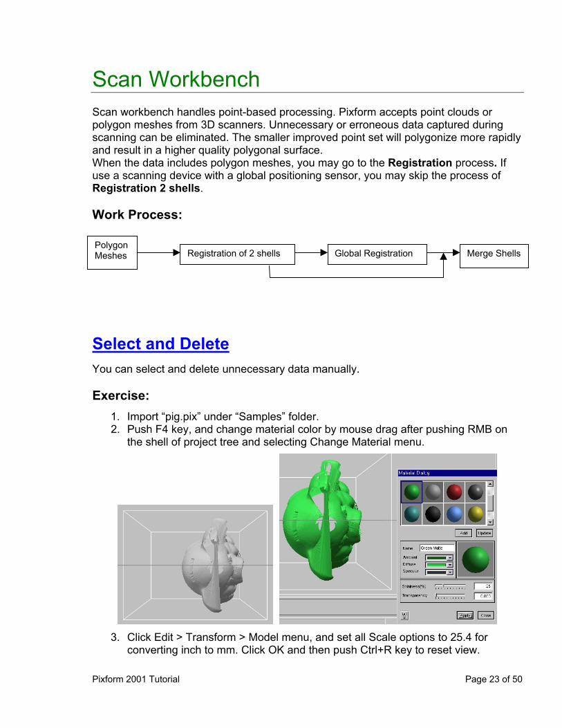
Scan Workbench Scan workbench handles point-based processing. Pixform accepts point clouds or polygon meshes from 3D scanners. Unnecessary or erroneous data captured during scanning can be eliminated. The smaller improved point set will polygonize more rapidly and result in a higher quality polygonal surface. When the data includes polygon meshes, you may go to the Registration process. If use a scanning device with a global positioning sensor, you may skip the process of Registration 2 shells. Work Process:
Registration of 2 shells Global Registration Merge ShellsPolygon Meshes
Select and Delete You can select and delete unnecessary data manually. Exercise:
1. 2.
Import “pig.pix” under “Samples” folder. Push F4 key, and change material color by mouse drag after pushing RMB on the shell of project tree and selecting Change Material menu.
3. Click Edit > Transform > Model menu, and set all Scale options to 25.4 for
converting inch to mm. Click OK and then push Ctrl+R key to reset view.
Pixform 2001 Tutorial Page 23 of 50
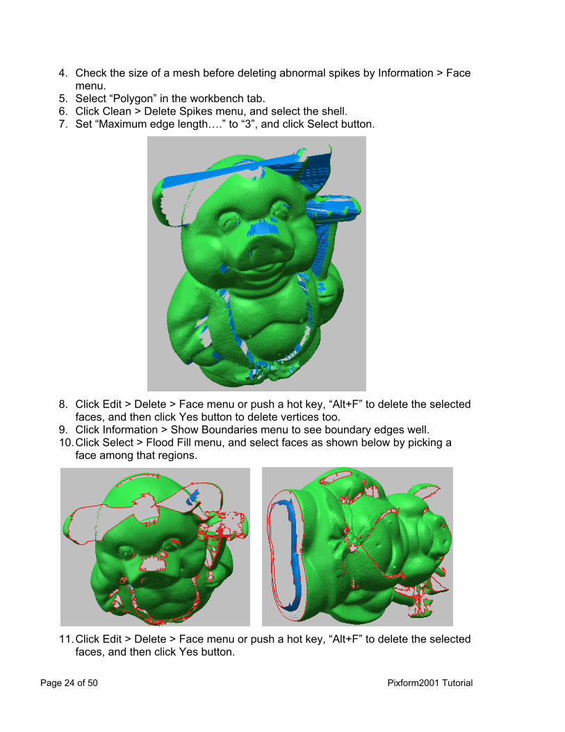
4.
5. 6. 7.
Check the size of a mesh before deleting abnormal spikes by Information > Face menu. Select “Polygon” in the workbench tab. Click Clean > Delete Spikes menu, and select the shell. Set “Maximum edge length….” to “3”, and click Select button.
8.
9. 10.
Click Edit > Delete > Face menu or push a hot key, “Alt+F” to delete the selected faces, and then click Yes button to delete vertices too. Click Information > Show Boundaries menu to see boundary edges well. Click Select > Flood Fill menu, and select faces as shown below by picking a face among that regions.
11. Click Edit > Delete > Face menu or push a hot key, “Alt+F” to delete the selected
faces, and then click Yes button.
Page 24 of 50 Pixform2001 Tutorial

12.13.14.15.16.17.18.19.
Hide “pig” shell in Project Window. Import “top.pix” under “Samples” folder, and apply Edit > Material operation. Click Edit > Transform > Shell menu, and select “top” shell in Project Window. Set all Scale options to 25.4 for converting inch to mm, and click OK. And then push Ctrl+R key to reset view. Click Clean > Delete Spikes menu, and select the shell. Set “Maximum edge length….” to “5”, and click Delete button. Click Select > Entities > Vertex menu or push a hot key, “Shift+V”, and then select unnecessary vertices irrelevant to the top view as shown below.
20. Click Edit > Delete> Vertex menu or push a hot key, “Alt+V” to delete the
selected vertices.
Pixform 2001 Tutorial Page 25 of 50
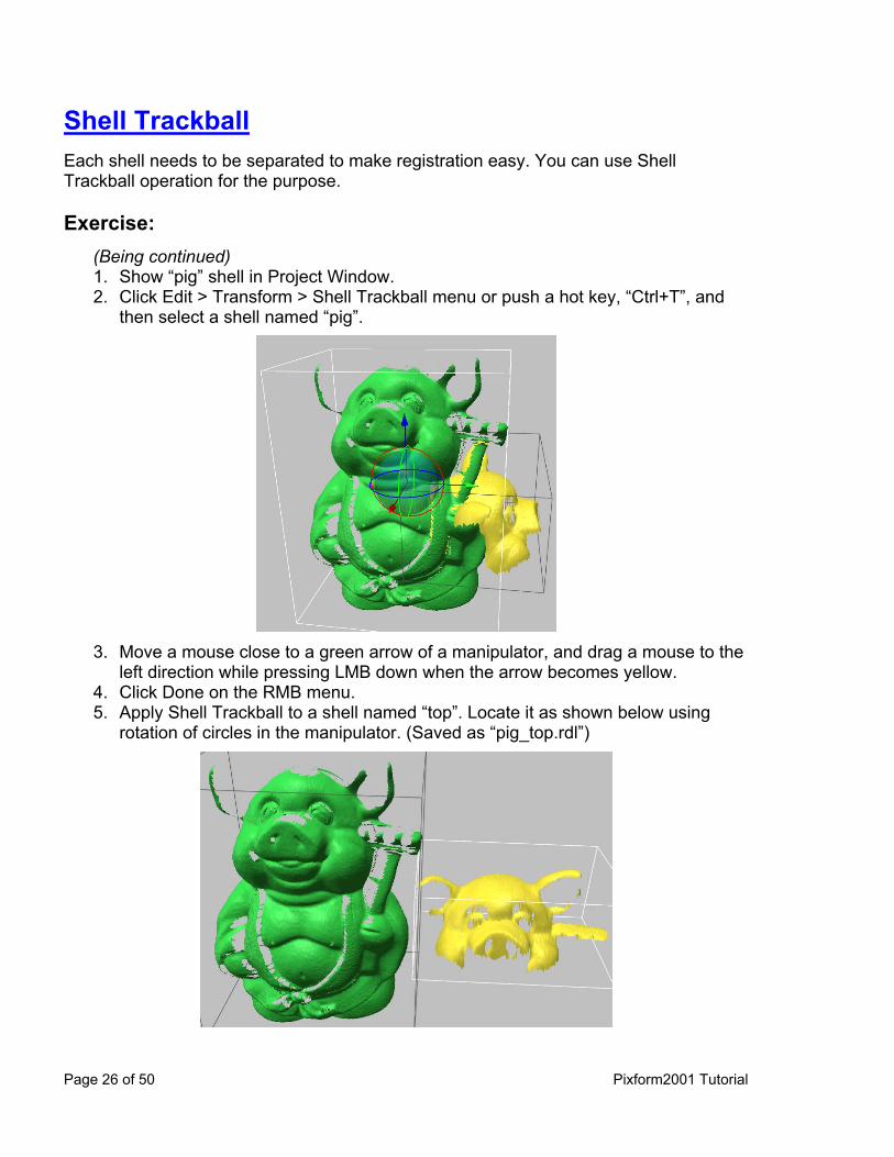
Shell Trackball Each shell needs to be separated to make registration easy. You can use Shell Trackball operation for the purpose. Exercise:
(Being continued) 1. 2.
Show “pig” shell in Project Window. Click Edit > Transform > Shell Trackball menu or push a hot key, “Ctrl+T”, and then select a shell named “pig”.
3.
4. 5.
Move a mouse close to a green arrow of a manipulator, and drag a mouse to the left direction while pressing LMB down when the arrow becomes yellow. Click Done on the RMB menu. Apply Shell Trackball to a shell named “top”. Locate it as shown below using rotation of circles in the manipulator. (Saved as “pig_top.rdl”)
Page 26 of 50 Pixform2001 Tutorial
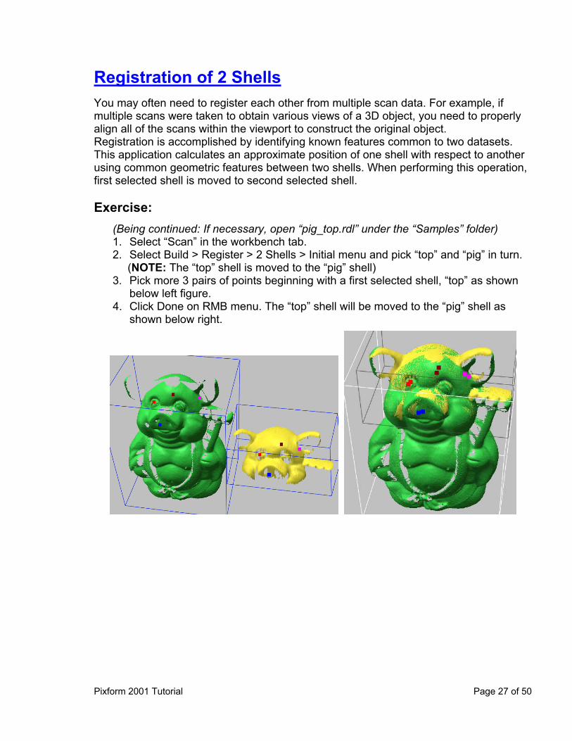
Registration of 2 Shells You may often need to register each other from multiple scan data. For example, if multiple scans were taken to obtain various views of a 3D object, you need to properly align all of the scans within the viewport to construct the original object. Registration is accomplished by identifying known features common to two datasets. This application calculates an approximate position of one shell with respect to another using common geometric features between two shells. When performing this operation, first selected shell is moved to second selected shell. Exercise:
(Being continued: If necessary, open “pig_top.rdl” under the “Samples” folder) 1. 2.
3.
4.
Select “Scan” in the workbench tab. Select Build > Register > 2 Shells > Initial menu and pick “top” and “pig” in turn. (NOTE: The “top” shell is moved to the “pig” shell) Pick more 3 pairs of points beginning with a first selected shell, “top” as shown below left figure. Click Done on RMB menu. The “top” shell will be moved to the “pig” shell as shown below right.
Pixform 2001 Tutorial Page 27 of 50
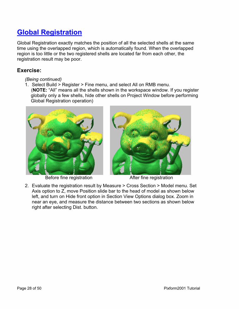
Global Registration Global Registration exactly matches the position of all the selected shells at the same time using the overlapped region, which is automatically found. When the overlapped region is too little or the two registered shells are located far from each other, the registration result may be poor. Exercise:
(Being continued) 1. Select Build > Register > Fine menu, and select All on RMB menu.
(NOTE: “All” means all the shells shown in the workspace window. If you register globally only a few shells, hide other shells on Project Window before performing Global Registration operation)
Before fine registration After fine registration
2. Evaluate the registration result by Measure > Cross Section > Model menu. Set Axis option to Z, move Position slide bar to the head of model as shown below left, and turn on Hide front option in Section View Options dialog box. Zoom in near an eye, and measure the distance between two sections as shown below right after selecting Dist. button.
Page 28 of 50 Pixform2001 Tutorial
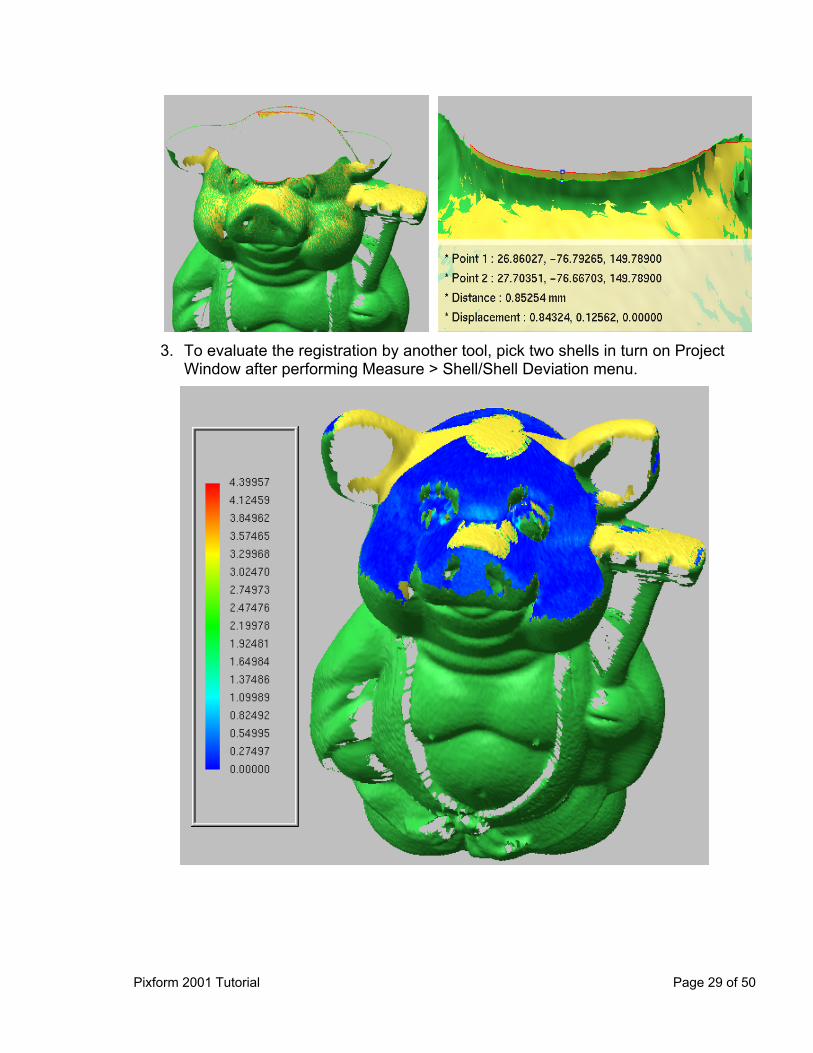
3. To evaluate the registration by another tool, pick two shells in turn on Project
Window after performing Measure > Shell/Shell Deviation menu.
Pixform 2001 Tutorial Page 29 of 50
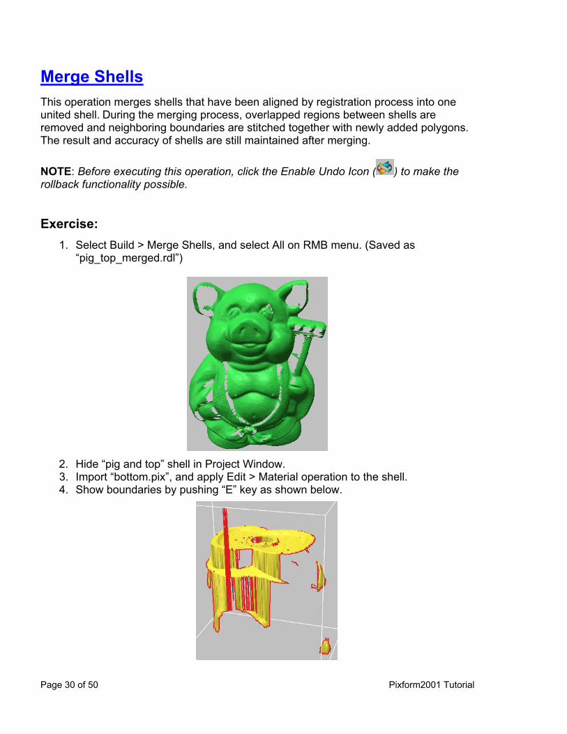
Merge Shells This operation merges shells that have been aligned by registration process into one united shell. During the merging process, overlapped regions between shells are removed and neighboring boundaries are stitched together with newly added polygons. The result and accuracy of shells are still maintained after merging. NOTE: Before executing this operation, click the Enable Undo Icon ( ) to make the rollback functionality possible. Exercise:
1. Select Build > Merge Shells, and select All on RMB menu. (Saved as “pig_top_merged.rdl”)
2. 3. 4.
Hide “pig and top” shell in Project Window. Import “bottom.pix”, and apply Edit > Material operation to the shell. Show boundaries by pushing “E” key as shown below.
Page 30 of 50 Pixform2001 Tutorial

5. 6.
7.
Select “Polygon” in the workbench tab. Apply Clean > Delete Spikes to the shell, and delete faces which edge is larger than 5. Apply Clean > Delete Singularities to the shell with default options. Push a hot key, “Shift+V”, and then select unnecessary vertices irrelevant to the bottom view as shown below. Push a hot key, “Alt+V” to delete the selected vertices.
8. 9.
Show “pig and top” shell in Project Window. Apply Shell Trackball to “bottom” shell as shown below.
10. Apply Registration and Merge operations to “pig and top” and to “bottom” shells.
(Saved as “pig_top_bottom_merged.rdl”)
Pixform 2001 Tutorial Page 31 of 50

11. Repeat above 2 to 10 processes with “side1.pix” file. (Saved as “pig_top_bottom_side1_merged.rdl”) (NOTE: It is better to delete unnecessary vertices before merging to get the result to be wished)
Registered Merged
12. Repeat above 2 to 10 processes with “side2.pix” file. (Saved as “all_merged.rdl”)
Registered Merged
Page 32 of 50 Pixform2001 Tutorial
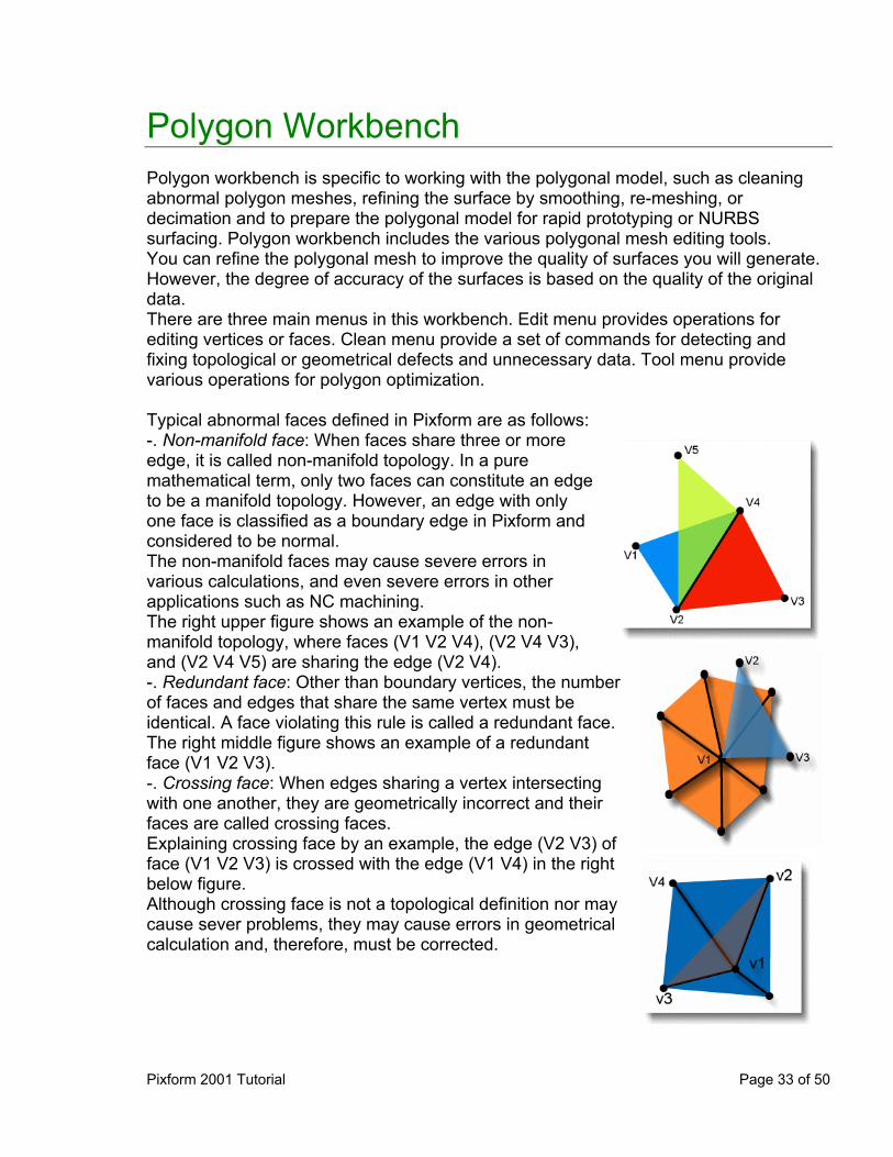
Polygon Workbench Polygon workbench is specific to working with the polygonal model, such as cleaning abnormal polygon meshes, refining the surface by smoothing, re-meshing, or decimation and to prepare the polygonal model for rapid prototyping or NURBS surfacing. Polygon workbench includes the various polygonal mesh editing tools. You can refine the polygonal mesh to improve the quality of surfaces you will generate. However, the degree of accuracy of the surfaces is based on the quality of the original data. There are three main menus in this workbench. Edit menu provides operations for editing vertices or faces. Clean menu provide a set of commands for detecting and fixing topological or geometrical defects and unnecessary data. Tool menu provide various operations for polygon optimization. Typical abnormal faces defined in Pixform are as follows: -. Non-manifold face: When faces share three or more edge, it is called non-manifold topology. In a pure mathematical term, only two faces can constitute an edge to be a manifold topology. However, an edge with only one face is classified as a boundary edge in Pixform and considered to be normal. The non-manifold faces may cause severe errors in various calculations, and even severe errors in other applications such as NC machining. The right upper figure shows an example of the non-manifold topology, where faces (V1 V2 V4), (V2 V4 V3), and (V2 V4 V5) are sharing the edge (V2 V4). -. Redundant face: Other than boundary vertices, the number of faces and edges that share the same vertex must be identical. A face violating this rule is called a redundant face. The right middle figure shows an example of a redundant face (V1 V2 V3). -. Crossing face: When edges sharing a vertex intersecting with one another, they are geometrically incorrect and their faces are called crossing faces. Explaining crossing face by an example, the edge (V2 V3) of face (V1 V2 V3) is crossed with the edge (V1 V4) in the right below figure. Although crossing face is not a topological definition nor may cause sever problems, they may cause errors in geometrical calculation and, therefore, must be corrected.
Pixform 2001 Tutorial Page 33 of 50
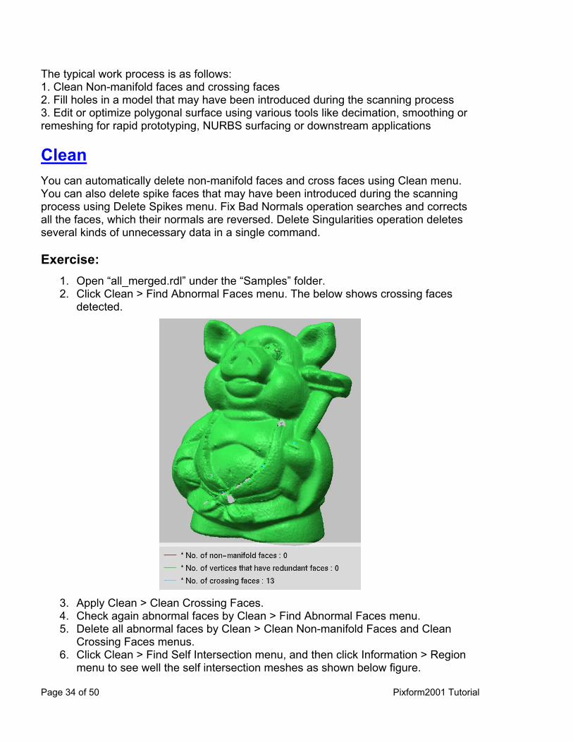
The typical work process is as follows: 1. Clean Non-manifold faces and crossing faces 2. Fill holes in a model that may have been introduced during the scanning process 3. Edit or optimize polygonal surface using various tools like decimation, smoothing or remeshing for rapid prototyping, NURBS surfacing or downstream applications Clean You can automatically delete non-manifold faces and cross faces using Clean menu. You can also delete spike faces that may have been introduced during the scanning process using Delete Spikes menu. Fix Bad Normals operation searches and corrects all the faces, which their normals are reversed. Delete Singularities operation deletes several kinds of unnecessary data in a single command. Exercise:
1. 2.
Open “all_merged.rdl” under the “Samples” folder. Click Clean > Find Abnormal Faces menu. The below shows crossing faces detected.
3. 4. 5.
6.
Apply Clean > Clean Crossing Faces. Check again abnormal faces by Clean > Find Abnormal Faces menu. Delete all abnormal faces by Clean > Clean Non-manifold Faces and Clean Crossing Faces menus. Click Clean > Find Self Intersection menu, and then click Information > Region menu to see well the self intersection meshes as shown below figure.
Page 34 of 50 Pixform2001 Tutorial
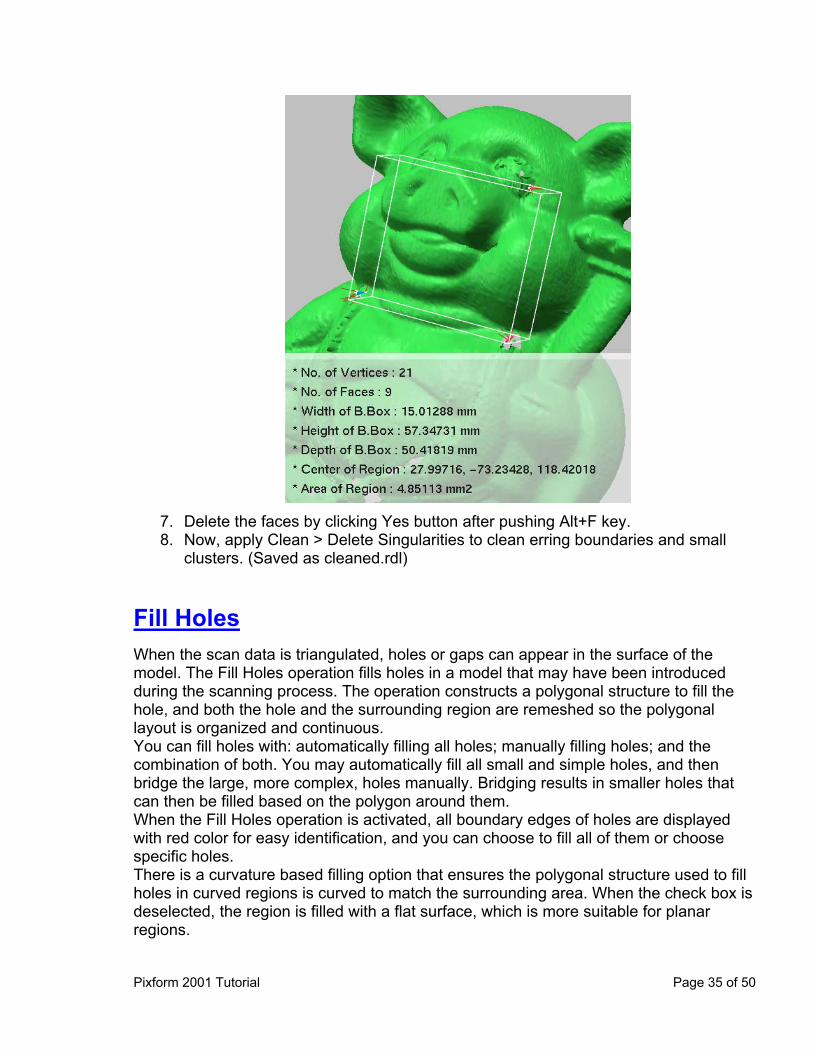
7. 8.
Delete the faces by clicking Yes button after pushing Alt+F key. Now, apply Clean > Delete Singularities to clean erring boundaries and small clusters. (Saved as cleaned.rdl)
Fill Holes When the scan data is triangulated, holes or gaps can appear in the surface of the model. The Fill Holes operation fills holes in a model that may have been introduced during the scanning process. The operation constructs a polygonal structure to fill the hole, and both the hole and the surrounding region are remeshed so the polygonal layout is organized and continuous. You can fill holes with: automatically filling all holes; manually filling holes; and the combination of both. You may automatically fill all small and simple holes, and then bridge the large, more complex, holes manually. Bridging results in smaller holes that can then be filled based on the polygon around them. When the Fill Holes operation is activated, all boundary edges of holes are displayed with red color for easy identification, and you can choose to fill all of them or choose specific holes. There is a curvature based filling option that ensures the polygonal structure used to fill holes in curved regions is curved to match the surrounding area. When the check box is deselected, the region is filled with a flat surface, which is more suitable for planar regions.
Pixform 2001 Tutorial Page 35 of 50
NOTE: The Fill Holes operation can be applied an entire shell or locally selected region. Exercise:
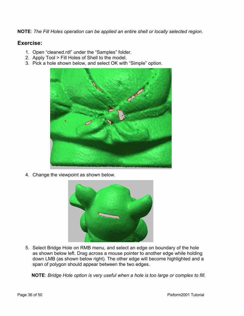
1. 2. 3.
Open “cleaned.rdl” under the “Samples” folder. Apply Tool > Fill Holes of Shell to the model. Pick a hole shown below, and select OK with “Simple” option.
4. Change the viewpoint as shown below.
5. Select Bridge Hole on RMB menu, and select an edge on boundary of the hole
as shown below left. Drag across a mouse pointer to another edge while holding down LMB (as shown below right). The other edge will become highlighted and a span of polygon should appear between the two edges.
NOTE: Bridge Hole option is very useful when a hole is too large or complex to fill.
Page 36 of 50 Pixform2001 Tutorial

Step 1
Step 2
6. To accept a bridge, release the mouse. A bridge is created between the starting edge and the destination edge (as shown below).
7.
8.
Select a specific hole or click Next button on Hole Selection Options to find easily another holes, and fill it. Click All on RMB menu, and then push OK with default options.
Pixform 2001 Tutorial Page 37 of 50
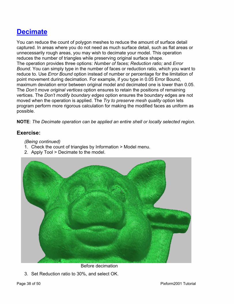
Decimate You can reduce the count of polygon meshes to reduce the amount of surface detail captured. In areas where you do not need as much surface detail, such as flat areas or unnecessarily rough areas, you may wish to decimate your model. This operation reduces the number of triangles while preserving original surface shape. The operation provides three options: Number of faces; Reduction ratio; and Error Bound. You can simply type in the number of faces or reduction ratio, which you want to reduce to. Use Error Bound option instead of number or percentage for the limitation of point movement during decimation. For example, if you type in 0.05 Error Bound, maximum deviation error between original model and decimated one is lower than 0.05. The Don’t move original vertices option ensures to retain the positions of remaining vertices. The Don’t modify boundary edges option ensures the boundary edges are not moved when the operation is applied. The Try to preserve mesh quality option lets program perform more rigorous calculation for making the modified faces as uniform as possible. NOTE: The Decimate operation can be applied an entire shell or locally selected region. Exercise:
(Being continued) 1. 2.
Check the count of triangles by Information > Model menu. Apply Tool > Decimate to the model.
Before decimation
3. Set Reduction ratio to 30%, and select OK.
Page 38 of 50 Pixform2001 Tutorial
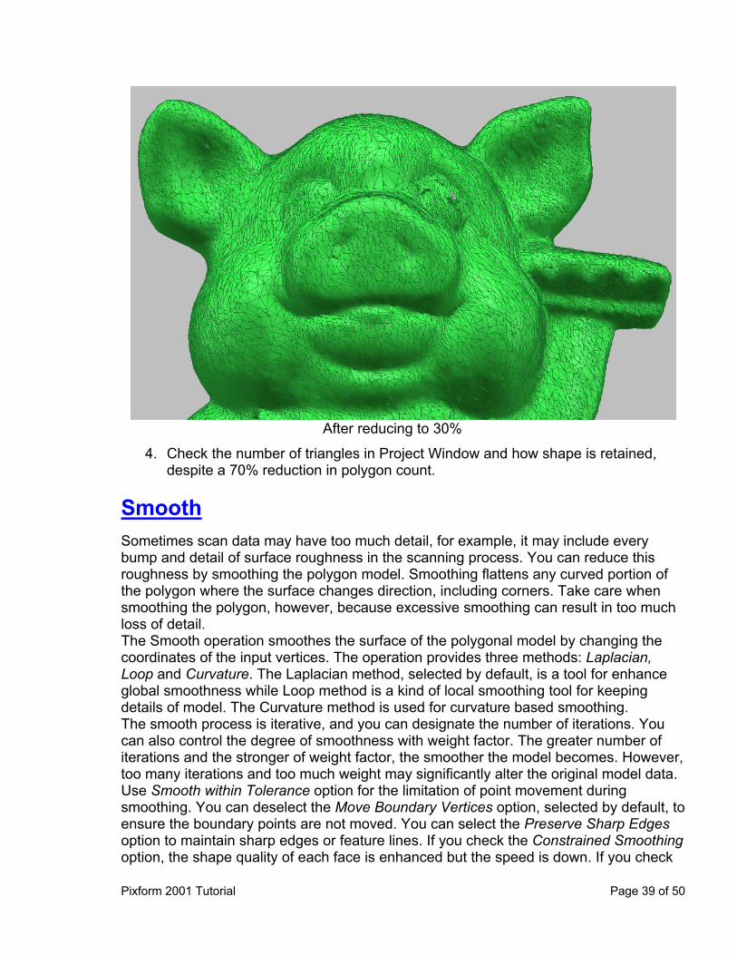
After reducing to 30%
4. Check the number of triangles in Project Window and how shape is retained, despite a 70% reduction in polygon count.
Smooth Sometimes scan data may have too much detail, for example, it may include every bump and detail of surface roughness in the scanning process. You can reduce this roughness by smoothing the polygon model. Smoothing flattens any curved portion of the polygon where the surface changes direction, including corners. Take care when smoothing the polygon, however, because excessive smoothing can result in too much loss of detail. The Smooth operation smoothes the surface of the polygonal model by changing the coordinates of the input vertices. The operation provides three methods: Laplacian, Loop and Curvature. The Laplacian method, selected by default, is a tool for enhance global smoothness while Loop method is a kind of local smoothing tool for keeping details of model. The Curvature method is used for curvature based smoothing. The smooth process is iterative, and you can designate the number of iterations. You can also control the degree of smoothness with weight factor. The greater number of iterations and the stronger of weight factor, the smoother the model becomes. However, too many iterations and too much weight may significantly alter the original model data. Use Smooth within Tolerance option for the limitation of point movement during smoothing. You can deselect the Move Boundary Vertices option, selected by default, to ensure the boundary points are not moved. You can select the Preserve Sharp Edges option to maintain sharp edges or feature lines. If you check the Constrained Smoothing option, the shape quality of each face is enhanced but the speed is down. If you check
Pixform 2001 Tutorial Page 39 of 50
the Preserve Volume option, the total volume of model will be preserved, thus prevent polygonal model shrinkage, during the smoothing process. NOTE: The Smooth operation can be applied an entire shell or locally selected region.
Also you can use the paint tool to smooth locally in real time. Exercise:
(Being continued) 1. 2. 3. 4.
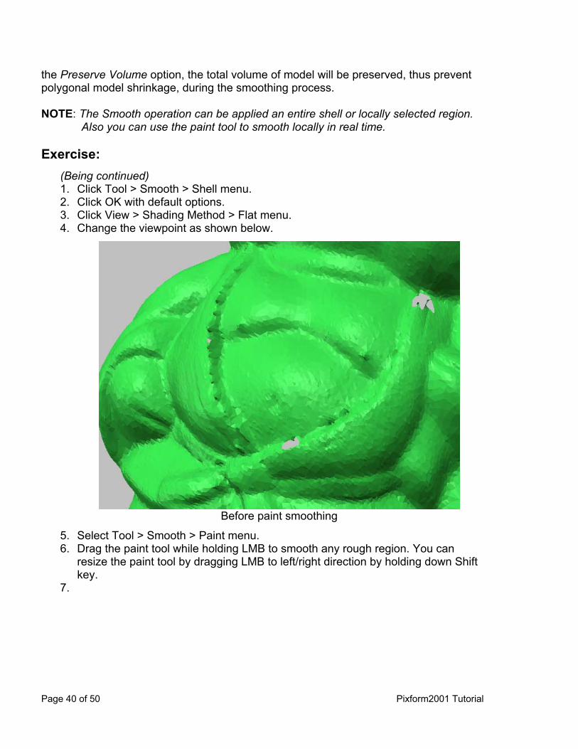
Click Tool > Smooth > Shell menu. Click OK with default options. Click View > Shading Method > Flat menu. Change the viewpoint as shown below.
Before paint smoothing
5. 6.
7.
Select Tool > Smooth > Paint menu. Drag the paint tool while holding LMB to smooth any rough region. You can resize the paint tool by dragging LMB to left/right direction by holding down Shift key.
Page 40 of 50 Pixform2001 Tutorial
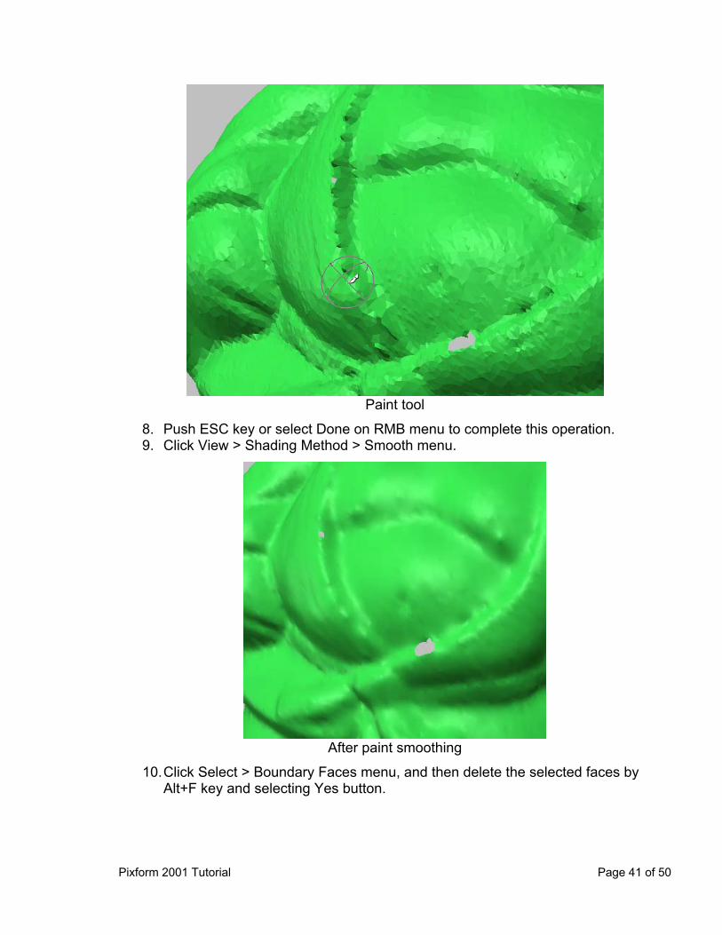
Paint tool
8. 9.
Push ESC key or select Done on RMB menu to complete this operation. Click View > Shading Method > Smooth menu.
After paint smoothing
10. Click Select > Boundary Faces menu, and then delete the selected faces by Alt+F key and selecting Yes button.
Pixform 2001 Tutorial Page 41 of 50

11.12.13.
Apply Clean > Delete Singularities to clean boundaries. Apply Tool > Fill Holes of Shell to the shell, and click All on RMB menu. Click Information > Show Boundaries menu to check whether there are any holes. (Saved as “smooth.rdl”)
Subdivide The Subdivide operation improves the surface of the polygonal model by adding new vertices and adjusting the coordinates of existing vertices, resulting in a greater number of triangles in the selected area and a smoother surface. The operation subdivides selected triangles, producing four triangles for every one original triangle. Each face is subdivided into four pieces by adding new 3 vertices on each edge of the face; not only are the new vertices to be added but the original vertex position is also recalculated, thus the continuity of the curvature is much improved. You can subdivide only the faces which edges are longer than the length you specify. You can select the Preserve Sharp Edges option to maintain sharp edges or feature lines. NOTE: The Subdivide operation can be applied an entire shell or locally selected region. Exercise:
(Being continued) 1. 2.
Click Tool > Subdivide Shell menu, and select the model. Click OK on dialog box.
Page 42 of 50 Pixform2001 Tutorial
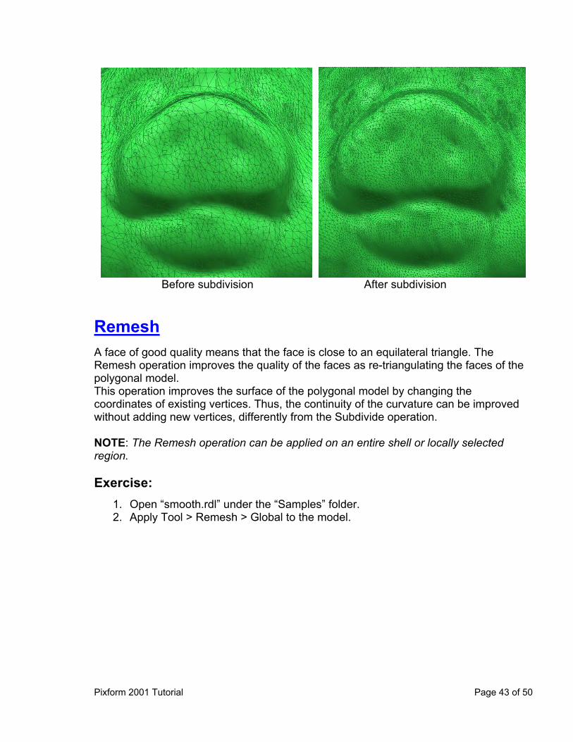
Before subdivision After subdivision
Remesh A face of good quality means that the face is close to an equilateral triangle. The Remesh operation improves the quality of the faces as re-triangulating the faces of the polygonal model. This operation improves the surface of the polygonal model by changing the coordinates of existing vertices. Thus, the continuity of the curvature can be improved without adding new vertices, differently from the Subdivide operation. NOTE: The Remesh operation can be applied on an entire shell or locally selected region. Exercise:
1. 2.
Open “smooth.rdl” under the “Samples” folder. Apply Tool > Remesh > Global to the model.
Pixform 2001 Tutorial Page 43 of 50
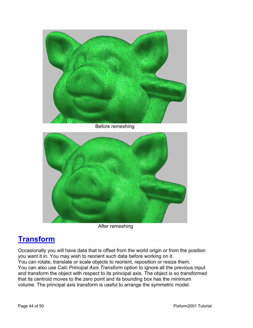
Before remeshing
After remeshing
Transform Occasionally you will have data that is offset from the world origin or from the position you want it in. You may wish to reorient such data before working on it. You can rotate, translate or scale objects to reorient, reposition or resize them. You can also use Calc Principal Axis Transform option to ignore all the previous input and transform the object with respect to its principal axis. The object is so transformed that its centroid moves to the zero point and its bounding box has the minimum volume. The principal axis transform is useful to arrange the symmetric model.
Page 44 of 50 Pixform2001 Tutorial
Exercise: (Being continued) 1. 2. 3.
Click Edit > Transform > Model menu. Set Rotate option to X= -90, Y= 0, Z= -90. Click OK, and then push Ctrl+R key. (Save as optimized.rdl)
Surface Workbench Pixform allows you to generate a watertight, smooth surface. You can create NURBS surface automatically. Automatic surface generation doesn’t need tedious curve drawing, so helps you speed up your surfacing work. Auto surfacing can use feature curves you predefined. You can evaluate the surface by plotting deviation between surface and original polygon and environment mapping. You can also evaluate continuities between adjacent surface patches. The typical work process is as follows:
1. 2. 3. 4. 5.
Fit NURBS surface to polygonal model Edit NURBS surface patches Analyze the surface Improve the continuity and smoothness Export to the downstream application
Auto Surfacing The Auto Surfacing operation automatically makes all patch boundaries and generates a watertight, smooth surface. You can determine boundary matching, and the amount of detail you want. Exercise 1: No Reference Shell
1. 2. 3. 4. 5.
Open “optimized.rdl” under the “Samples” folder. Select “Surface” in the workbench tabs. Select Surface > Auto Surfacing menu, pick the shell and itself as reference shell. Click Done on RMB menu. Set No. of Surfaces to 200, uncheck Match option, and then click OK.
Pixform 2001 Tutorial Page 45 of 50

Before auto surfacing After auto surfacing
Exercise 2: Use Reference Shell 1. 2. 3.
Delete all surfaces in Project Window, and go to the Polygon workbench. Duplicate the shell by pushing Ctrl+C and Ctrl+V keys. Apply Tool > Decimate to duplicate, and reduce to 100 faces.
NOTE: About 200 patches of surface, double the number of polygon mesh, will be created.
Original shell Duplicate decimated
Page 46 of 50 Pixform2001 Tutorial

4. 5.
6. 7. 8. 9.
Go to the Surface workbench. Click Surface > Auto Surfacing menu, select the original shell and the duplicate as reference shell in turn on the Project Window. Click Done on RMB menu. Uncheck Match option, and click OK with other default options. Select Surface > Options > Drawing Quality > Boundary Only menu. Render the surface by the hot key, R, and hide all entities by pushing the hot keys, 2 and 6.
Surface boundaries Rendering surface 10.11.12.13.
Show all surfaces by pushing the hot key, 5. Click Surface > Tool > Match menu, and then select all surfaces by mouse drag. Click Done on RMB menu. Click OK button with default options. (Saved as “auto_surfacing.rdl”)
Pixform 2001 Tutorial Page 47 of 50
Glossary The following sections define many of the basic terms and concepts you should know in order to use Pixform effectively. Aspect Ratio Ratio of width to height Boundary Borders of a model Boundary Edge Edge of a polygon that is not shared with another polygon C0 or G0 Continuity Positional continuity. Two surfaces that share a set of boundaries are C0 or G0 continuous when the adjoining edges of the surfaces match up exactly with respect to surface position. C1 or G1 Continuity Tangential continuity. Two surfaces that share a set of boundaries are C1 or G1 continuous when the normals at the boundaries of those surfaces are exactly aligned in direction and are the same in magnitude. CAD Computer Aided Design Control Points A set of points that parameterize and control the shape of a NURBS curve or surface Decimation An operation that reduces the count of entities. This operation usually attempts to preserve the object's overall shape and sharp features. Edge Line between two connected vertices on a polygon Face A face is a triangle composed of three vertices, and it is defined as three edges connected with each other. GUI Graphic User Interface
Page 48 of 50 Pixform2001 Tutorial
IGES Initial Graphics Exchange Specification, the standard for exchanging geometric information Isocurve(Iso-parameter curve) A set of curves on the surface that occur in the UV direction and define the surface shape. A parametric surface is typically crossed with flow lines that are constant U or V parameter curves on the surface, which are referred to either as isocurves. LMB Left Mouse Button Manipulator An interactive control device, which is usually used to transform an object Model A model is a logical set of several shells. Only one model can exist on the workspace window. Mouse Drag Moving the mouse while pressing and holding the mouse button. Normal A vector perpendicular to a polygonal mesh NURBS Non-Uniform Rational B-Spline. This is a type of spline where the curve passes close to but not through the control points or knots and used in spline-based modeling. Parameterization The flow of the curves defining a parametric surface Point Cloud (or Point Set) A point cloud is defined as a set of points in 3D space. A point cloud may consist of a single point or several million points. In Pixform, the number of points in a point cloud is limited only by the memory limitations of the host computer. Polyline A collection of n lines defined by the n +1 points that define the endpoints of each line segment Polygonal model A model composed of polygon faces.
Pixform 2001 Tutorial Page 49 of 50
Page 50 of 50 Pixform2001 Tutorial
Region A region is a user-selected set of vertex or face, which is just a temporary set in the job process. A region is released after the corresponding job is finished. RMB Right Mouse Button Shell A shell is a logical set of several faces. Faces are usually connected with each other, but not always. Normally, polygon meshes obtained through triangulation process of a point cloud measured on one view are managed as a shell. STL Stereo Lithography file format Surface A surface is defined as a mathematical function that describes the geometry fit to polygonal meshes. A surface(called patch) is bounded by iso-parameter curves(called flow line), controlled by a selected set of control points in the bi-direction, U-direction and V-direction. The surface is divided into 2 types, untrimmed and trimmed surface. The untrimmed surface has 4 boundary curves, while the trimmed surface has 2, 3, or more than 4 boundary curves. The trimmed surface is a special type of surface that is trimmed by its boundary curves after a basic surface, that is, an untrimmed surface is generated. Pixform uses NURBS to represent the surface geometry. Topology Data that tells the software how to connect the entities Vertex A single point defined by its Cartesian coordinates(X, Y and Z)
World Coordinates
In 3D space, a coordinate system that enables the software and the artist to establish an exact location for objects, lights, or cameras. The origin of the world coordinate system is (0, 0, 0).