tushar project
TRANSCRIPT
INTRODUCTION TO Central Acquisition
Radar (3D-CAR) – ROHINI / REVATHI
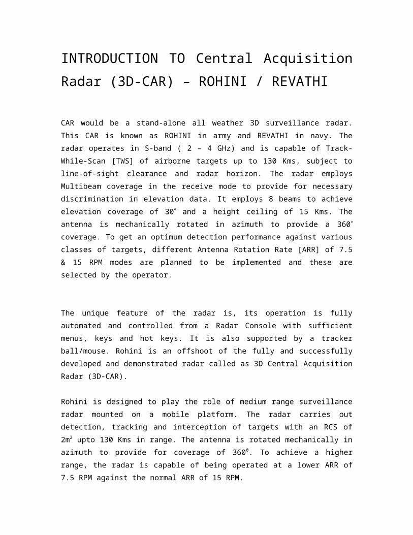
CAR would be a stand-alone all weather 3D surveillance radar. This CAR is
known as ROHINI in army and REVATHI in navy. The radar operates in S-band
( 2 – 4 GHz) and is capable of Track-While-Scan [TWS] of airborne targets up
to 130 Kms, subject to line-of-sight clearance and radar horizon. The radar
employs Multibeam coverage in the receive mode to provide for necessary
discrimination in elevation data. It employs 8 beams to achieve elevation
coverage of 30 and a height ceiling of 15 Kms. The antenna is mechanically
rotated in azimuth to provide a 360 coverage. To get an optimum detection
performance against various classes of targets, different Antenna Rotation
Rate [ARR] of 7.5 & 15 RPM modes are planned to be implemented and these
are selected by the operator.
The unique feature of the radar is, its operation is fully automated and
controlled from a Radar Console with sufficient menus, keys and hot keys. It is
also supported by a tracker ball/mouse. Rohini is an offshoot of the fully and
successfully developed and demonstrated radar called as 3D Central
Acquisition Radar (3D-CAR).
Rohini is designed to play the role of medium range surveillance radar
mounted on a mobile platform. The radar carries out detection, tracking and
interception of targets with an RCS of 2m2 upto 130 Kms in range. The
antenna is rotated mechanically in azimuth to provide for coverage of 3600.
To achieve a higher range, the radar is capable of being operated at a lower
ARR of 7.5 RPM against the normal ARR of 15 RPM.
Rohini is provided with all terrain mobility and various modes of
transportation. To achieve this goal a versatile mobile platform is developed.
This product is fitted on a TATRA class of vehicle.

CAR has the following subsystems
a) Multi-beam Antenna system
b) Transmitter
c) Receiver
d) Signal Processor
e) Radar Data Extractor
f) Radar Data Processor
g) Radar Controller
h) Radar Console
i) Electronic Equipment Cabin
j) Data centre
k) Mobile Power Source
l) IFF System
The Multibeam antenna system for Rohini is planned to be realized to have
360 Coverage in Azimuth and 30 Coverage in elevation. The antenna will
have a wide beam in transmit mode and eight simultaneous narrow beams in
receive mode to give 30 Coverage in elevation.
The requirement of Transmitter is to amplify the pulsed RF signal from 1W to
140kW while maintaining the phase noise (additive noise) to –60dBc/Hz at
100Hz away as demanded by the system.
The antenna can be manually positioned at different look angles in steps of
0.50,
covering – 2 degrees to +1 degree from normal position. In the receive mode
the eight beams cater for a height coverage of greater than 15 Kms. The IFF
antenna is placed atop the main antenna
LAN interfaces are used to communicate with external systems. High-speed
data transfer of target parameters can be done. This helps in data remoting
upto a distance of 500 mtrs that can be extended with suitable repeaters.
The Radar Console is a local display. The color display has features for
monitoring of radar performance, the radar output selection for radar modes of
operation. Interfaces to radar control signals are built-in. The Radar generates
different videos viz., Analog and Digital videos at the Receiver and Signal
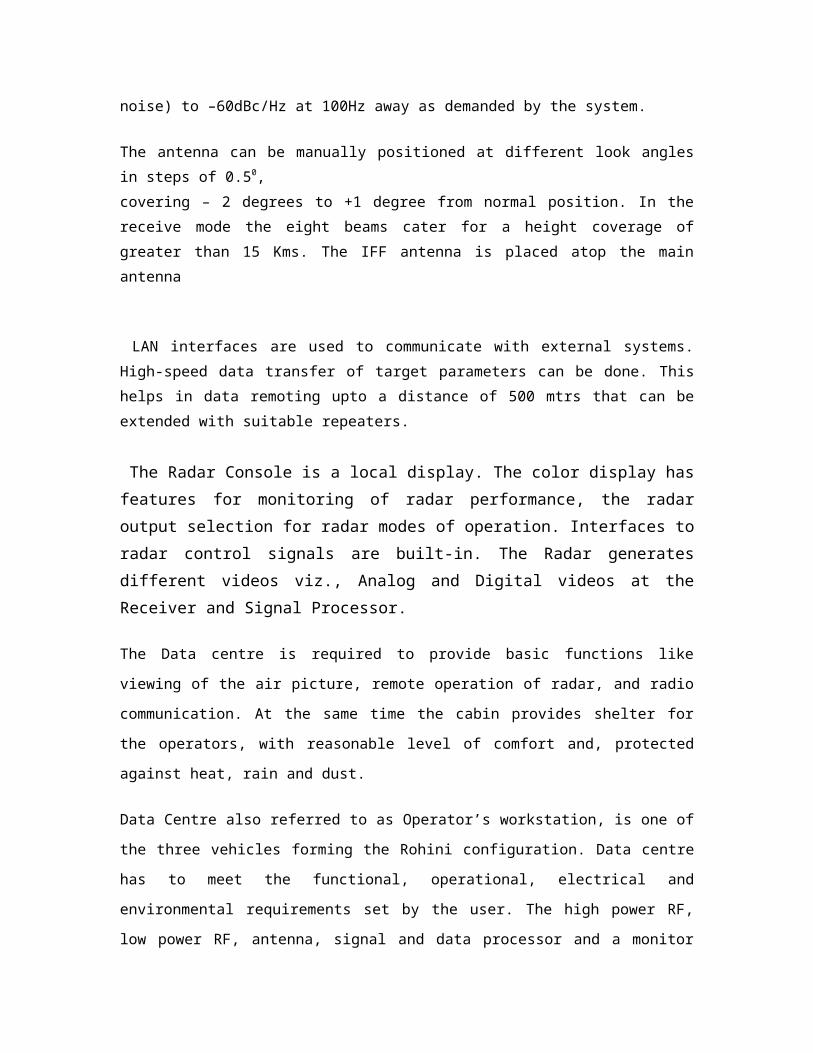
Processor.
The Data centre is required to provide basic functions like viewing of the air
picture, remote operation of radar, and radio communication. At the same
time the cabin provides shelter for the operators, with reasonable level of
comfort and, protected against heat, rain and dust.
Data Centre also referred to as Operator’s workstation, is one of the three
vehicles forming the Rohini configuration. Data centre has to meet the
functional, operational, electrical and environmental requirements set by the
user. The high power RF, low power RF, antenna, signal and data processor
and a monitor console are all integrated into the sensor vehicle.
This can, if needed, provide autonomous radar functionality. Data Centre will
be separated from the sensor by maximum of 100 mts. The two are
connected for exchange of data and control messages.
Mobile power source is required to provide the main supply to Radar Sensor
and Data Centre for electronic and mechanical units of Radar including air
conditioning units. The total power requirement for both vehicles is approx.
60KVA.
The radar normally operates at 15 RPM to get the optimum detection
performance up to 150 Km against fighter class of aircraft. 7.5 RPM mode will
be selected for getting higher detection ranges against larger cross-section
targets [up to 200 Km]. 15 RPM mode is specifically provided, where faster
update is needed.
The Identification Friend or Foe (IFF) system is a good example of a secondary
radar system that is in wide use in the military environment. A great deal of
valuable information can be provided to the secondary radar by.
the target’s transponder. The transponder provides an identifying code to the
secondary radar that then uses the code and an associated data base system
to look up aircraft origin and destination, flight number, aircraft type and
even the numbers of personnel onboard. This type of information is clearly

not available from a primary radar system
Sl.No
ITEM REVATHI ROHINI
1.Antenna Elevation coverage
Up to 50° Up to 30°
2.Antenna Weight
< 2400 kg. -
3. No. of 8+1 7+1
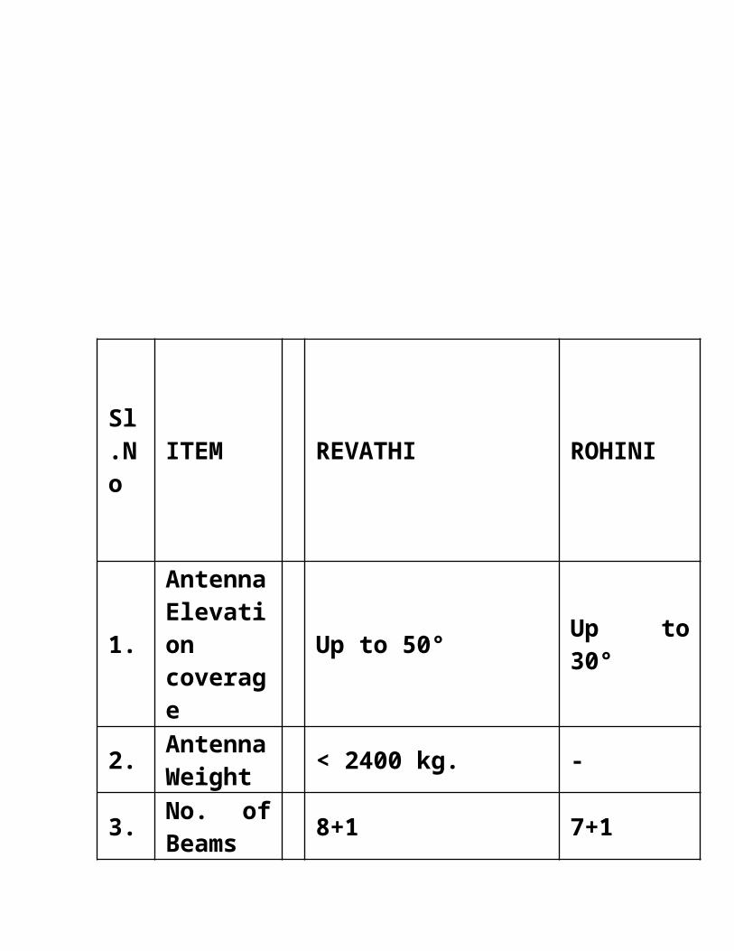
Beams
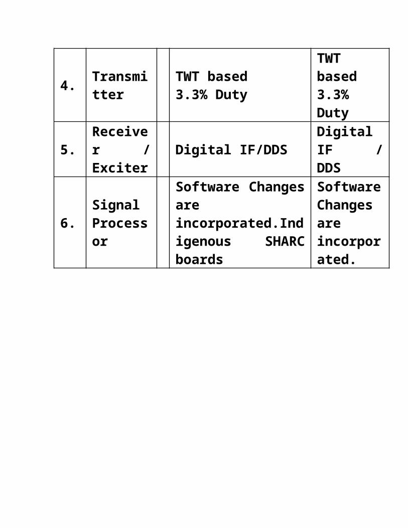
4.Transmitter
TWT based3.3% Duty
TWT based3.3% Duty
5.Receiver / Exciter
Digital IF/DDSDigital IF / DDS
6.Signal Processor
Software Changes are incorporated.Indigenous SHARC boards
Software Changes are incorporated.
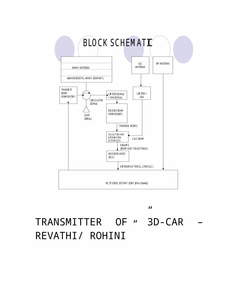
ARRAY ANTENNA
(4x8 HORIZONTAL ARRAY SEGMENT)
SLC ANTENNA
IFF ANTENNA
LIMITER +LNA
TRANSMIT BEAMFORMER(TBF)
LIMITER(32 Nos)+ LNA(32 Nos.)
RECEIVE BEAM FORMER(RBF)
RF, IF VIDEO, ROTARY JOINT (8 Rx Channel)
LOAD(32Nos.)
7 NARROW BEAMS
CIRCULATOR(32 Nos)
COLLECTING ANDDISTRIBUTION SYSTEM(CDS)
RECEIVER UNITS(RCV)
8 BEAMS(BEAM 6 OR 7 SELECTABLE)
8 IF BEAMS(7 FOR EL, 1 FOR SLC)
1 SLC BEAM
BLOCK SCHEMATIC
TRANSMITTER OF ”3D-CAR – REVATHI/ ROHINI”
SCOPE: The transmitter of CAR is capable of delivering RF peak power of greater
than 140 KW and RF average peak power greater than 4 KW. The transmitter
uses fully indigenous technology established by LRDE for 3D CAR
programme. The transmitter is planned to be realized as production version
M/S BEL Bangalore based on transfer of technology (TOT) from LRDE.
SALIENT FEATURES OF THE REVATHI / ROHINI RADAR
MANUAL / REMOTE OPERATION SECTOR BLANKING FACILITY FOR FULL 360 DEG AZIMUTHS USE OF 1.5KW SSPA FOR FAIL SAFE MODE OF OPERATION MODULAR DESIGN APPROCH FOR EASE OF MAINTAINABILITY HVPS: IGBT BASED FULL BRIDGE RESONANT CONVERTER USING PHASE
MODULATION TECHNIQUE FDM: SOLID STATE SWITCHING CPC: MICROCONTROLLER BASED PROTECTION
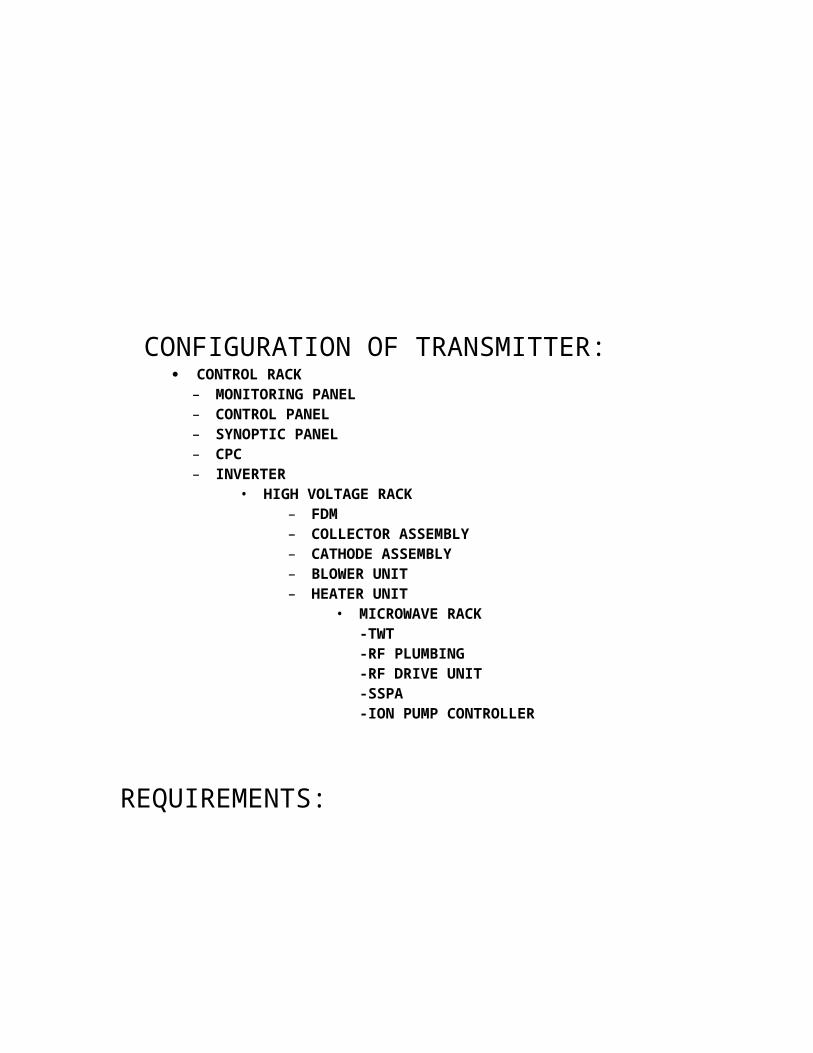
CONFIGURATION OF TRANSMITTER:
CONTROL RACK– MONITORING PANEL– CONTROL PANEL– SYNOPTIC PANEL– CPC– INVERTER
• HIGH VOLTAGE RACK– FDM– COLLECTOR ASSEMBLY– CATHODE ASSEMBLY– BLOWER UNIT– HEATER UNIT
• MICROWAVE RACK-TWT-RF PLUMBING-RF DRIVE UNIT-SSPA-ION PUMP CONTROLLER
REQUIREMENTS:
The requirement is to amplify the pulsed RF signal from 1W to 140 KW while
maintaining the phase noise (additive noise) to 60 dBz/Hz at 100 Hz away as
demanded by the system. In addition, a failsafe mode of delivering 2 KW of
peak power to antennae, in case of liquid coolant as redundant measure. RTS
-400 is the TWT based transmitter capable of delivering 140 KW of peak and
4 KW of average.
-600+800RF IN
RF OUTLIQUID COOLING
-45kV,5kW33kV,18kW
3kV,ION PUMP-10V,10A
TWT POWER SUPPLIES CONNECTION DIAGRAM

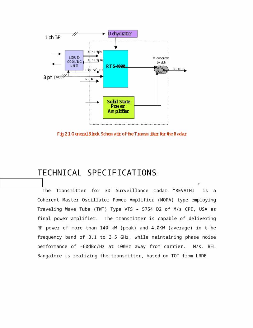
TECHNICAL SPECIFICATIONS:
The Transmitter for 3D Surveillance radar “REVATHI” is a Coherent Master
Oscillator Power Amplifier (MOPA) type employing Traveling Wave Tube (TWT)
Type VTS – 5754 D2 of M/s CPI, USA as final power amplifier. The transmitter
is capable of delivering RF power of more than 140 kW (peak) and 4.0KW
(average) in t he frequency band of 3.1 to 3.5 GHz, while maintaining phase
noise performance of –60dBc/Hz at 100Hz away from carrier. M/s. BEL
Bangalore is realizing the transmitter, based on TOT from LRDE.
The input output diagram of the transmitter is shown in fig 2.2.1. The
electrical specifications of the transmitter are:

8. Duty: T on / T on + T off = 3.2 % (max).
9. RF drive power level: (It has to be passed through this power level , before

passing through TWT ) : - 5 DBM to 13 DBM.
10. Blanking (screening of particular area from where a lot of energy is
coming): Sector blanking facility for full 360 degree azimuth.
11. Protection: crow bar protection technique is used. This method involves
grounding the power by using and gate and a triode.
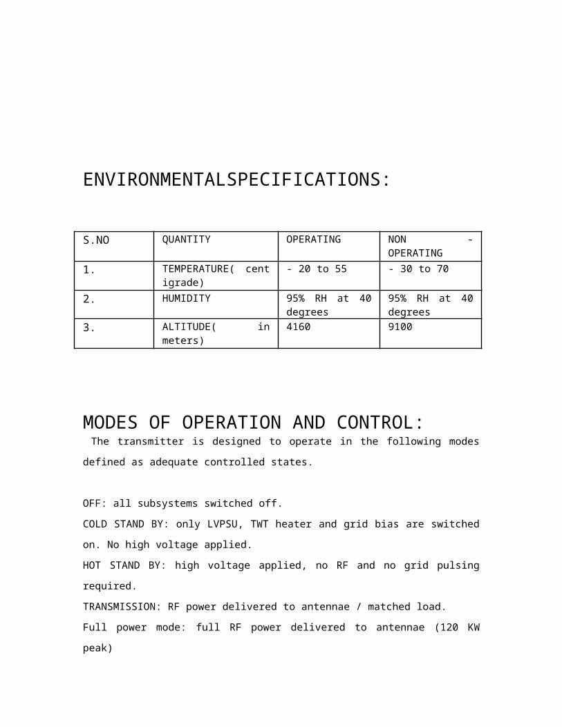
ENVIRONMENTALSPECIFICATIONS:

S.NO QUANTITY OPERATING NON - OPERATING
1. TEMPERATURE( centigrade)
- 20 to 55 - 30 to 70
2. HUMIDITY 95% RH at 40 degrees
95% RH at 40 degrees
3. ALTITUDE( in meters) 4160 9100
MODES OF OPERATION AND CONTROL: The transmitter is designed to operate in the following modes defined as
adequate controlled states.
OFF: all subsystems switched off.
COLD STAND BY: only LVPSU, TWT heater and grid bias are switched on. No
high voltage applied.
HOT STAND BY: high voltage applied, no RF and no grid pulsing required.
TRANSMISSION: RF power delivered to antennae / matched load.
Full power mode: full RF power delivered to antennae (120 KW peak)
Reduced power mode: The transmitter is operated at 1/ 10 of its full power
based on selection of the user.
Fail safe mode: A power of 1 KW peak at required duty is delivered to
antennae through Solid State Power Amplifier when liquid cooling fails.
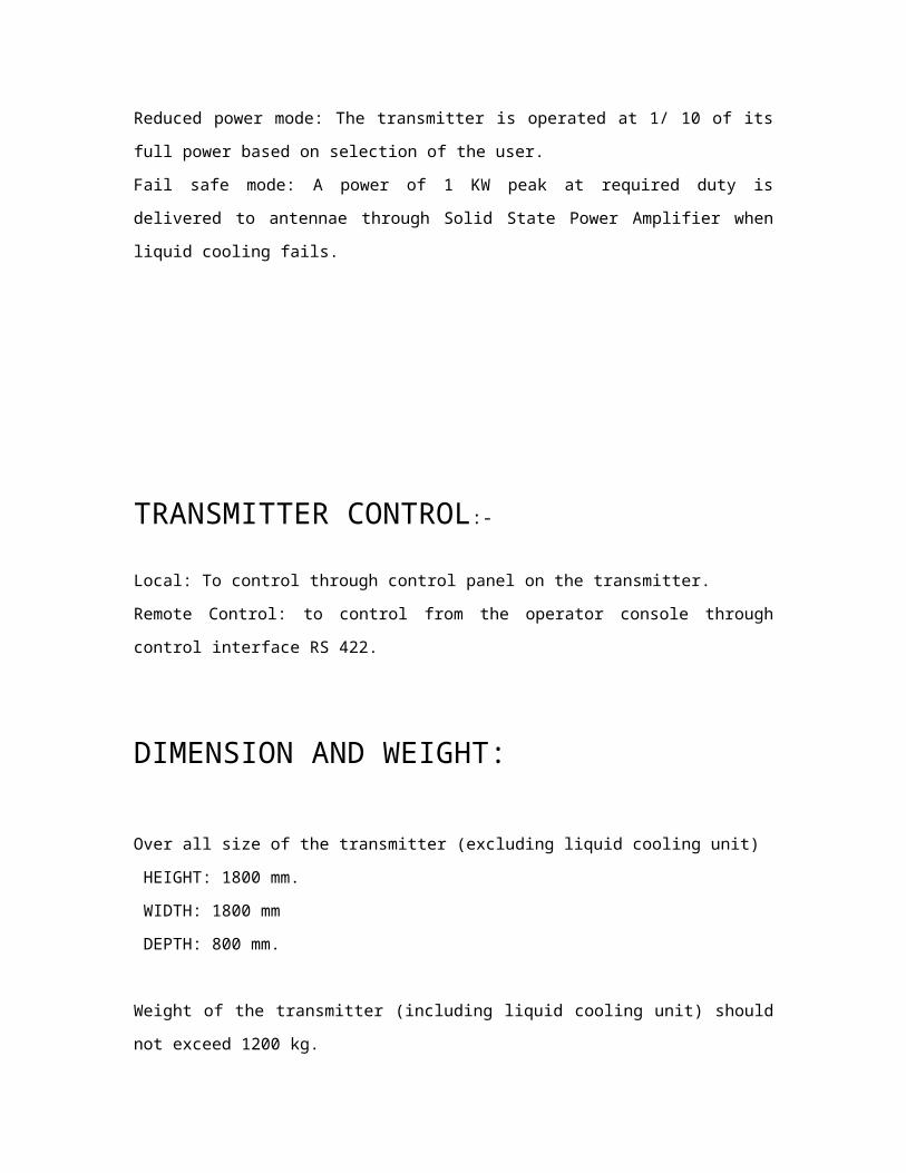
TRANSMITTER CONTROL:-
Local: To control through control panel on the transmitter.
Remote Control: to control from the operator console through control
interface RS 422.
DIMENSION AND WEIGHT:
Over all size of the transmitter (excluding liquid cooling unit)
HEIGHT: 1800 mm.
WIDTH: 1800 mm
DEPTH: 800 mm.
Weight of the transmitter (including liquid cooling unit) should not exceed
1200 kg.
GENERAL COOLING REQUIREMENT:
The system is a forced liquid-to-air type, used for cooling systems of the S-
Band Transmitter. The primary coolant used for circulation through this
transmitter heat loads is Dematerialized water / Glycol to catch for operation
from -20C to 55C. The transmitter employs liquid cooling for TWT, high
power circulator RF dummy load and high voltage power supplies and forced
air-cooling for all other sub-assemblies. Independent of air-cooling, a dry air
with low dew point and dust particles should be applied for wave-guide
pressurizing and for TWT.
General design of the cooling is worked out in such a way that the
temperature rise for outlet coolant is around 10C than the inlet. The total
heat load on liquid to air cooling unit is 25kW and for forced air cooling 3 kW.
The TWT, High Power Ferrite Isolator and high voltage power supplies are
cooled with de – ionized water and ethylene glycol mixture (50: 50). Liquid
cooling distribution is realized in such a way that the liquid cooling unit will
have a minimal pressure on the connections.
Forced air – cooling is employed to other components using the ambient air
properly filtered to ensure dust – free air. A dry air with low dew point and
dust particles is applied for wave guide channel.
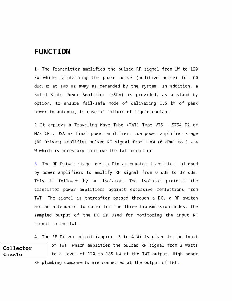
FUNCTION
1. The Transmitter amplifies the pulsed RF signal from 1W to 120 kW while
maintaining the phase noise (additive noise) to -60 dBc/Hz at 100 Hz away as
demanded by the system. In addition, a Solid State Power Amplifier (SSPA) is
provided, as a stand by option, to ensure fail-safe mode of delivering 1.5 kW
of peak power to antenna, in case of failure of liquid coolant.
2 It employs a Traveling Wave Tube (TWT) Type VTS - 5754 D2 of M/s CPI, USA
as final power amplifier. Low power amplifier stage (RF Driver) amplifies
pulsed RF signal from 1 mW (0 dBm) to 3 - 4 W which is necessary to drive
the TWT amplifier.
3. The RF Driver stage uses a Pin attenuator transistor followed by power
amplifiers to amplify RF signal from 0 dBm to 37 dBm. This is followed by an
isolator. The isolator protects the transistor power amplifiers against
excessive reflections from TWT. The signal is thereafter passed through a DC,
a RF switch and an attenuator to cater for the three transmission modes. The
sampled output of the DC is used for monitoring the input RF signal to the
TWT.
4. The RF Driver output (approx. 3 to 4 W) is given to the input of TWT, which
amplifies the pulsed RF signal from 3 Watts to a level of 120 to 185 kW at the
TWT output. High power RF plumbing components are connected at the
output of TWT.
Collector Supply

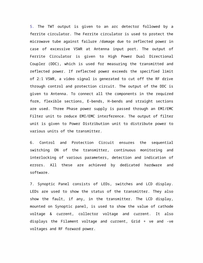
5. The TWT output is given to an arc detector followed by a ferrite circulator.
The Ferrite circulator is used to protect the microwave tube against failure
/damage due to reflected power in case of excessive VSWR at Antenna input
port. The output of Ferrite Circulator is given to High Power Dual Directional
Coupler (DDC), which is used for measuring the transmitted and reflected
power. If reflected power exceeds the specified limit of 2:1 VSWR, a video
signal is generated to cut off the RF drive through control and protection
circuit. The output of the DDC is given to Antenna. To connect all the
components in the required form, flexible sections, E-bends, H-bends and
straight sections are used. Three Phase power supply is passed through an
EMI/EMC Filter unit to reduce EMI/EMC interference. The output of filter unit is
given to Power Distribution unit to distribute power to various units of the
transmitter.
6. Control and Protection Circuit ensures the sequential switching ON of the
transmitter, continuous monitoring and interlocking of various parameters,
detection and indication of errors. All these are achieved by dedicated
hardware and software.
7. Synoptic Panel consists of LEDs, switches and LCD display. LEDs are used
to show the status of the transmitter. They also show the fault, if any, in the
transmitter. The LCD display, mounted on Synoptic panel, is used to show the
value of cathode voltage & current, collector voltage and current. It also
displays the Filament voltage and current, Grid + ve and -ve voltages and RF
forward power.
8. The Inverter unit converts the incoming ac supply to DC and then converts
the DC to high frequency AC (Pulse width controlled square wave) operating
at 20 kHz. The output of the Inverter unit is given to HV rack for generation of
Cathode and Collector voltages of the TWT amplifier.
9. High Voltage Power Supply unit (HVPSU) is used to supply high voltage to
collector and cathode of the TWT.
10. The Floating Deck Modulator (FDM) unit generates filament voltage with
surge current protection and also generates grid +ve and grid -ve voltages.
Switching of grid voltage as per pulse width and PRF requirements are also
provided by FDM.
Cooling Unit is used to cool the various components of the transmitter. The
TWT, High 11.Power Ferrite Isolator, high Voltage Power supplies and RF
dummy load are cooled with de-ionized water and ethylene glycol mixture
(50:50). Forced air-cooling is employed to cool other components using
ambient air which is filtered to ensure dust free air.
12. The Dry Air unit ensures that the wave guide is at all times pressurized
and dry.
General Mechanical Design
The transmitter consists of three metal racks containing respectively three
functional units: Microwave Unit (MU), Power Supply Unit (PSU), and Control
Unit (CU). All racks have front doors properly gasket for protection against
EMI.
At the upper part of each unit, above the door, slip panels containing RF
input, Transmitter pulse input, control and measurement connectors, control
lamps, hour meters, CBs and high voltage meters are placed. The Transmitter
is housed in 3 separate racks.
1. Microwave Rack consists of TWT, microwave plumbing components, SSPA
and RF driver.
2. High voltage rack Consists of all high voltage components and FDM
capacitor.
3. Control Rack Consisting of Monitoring and Diagnostics circuits, Control
Circuits, Power distribution along with line filter unit and high voltage inverter
unit.
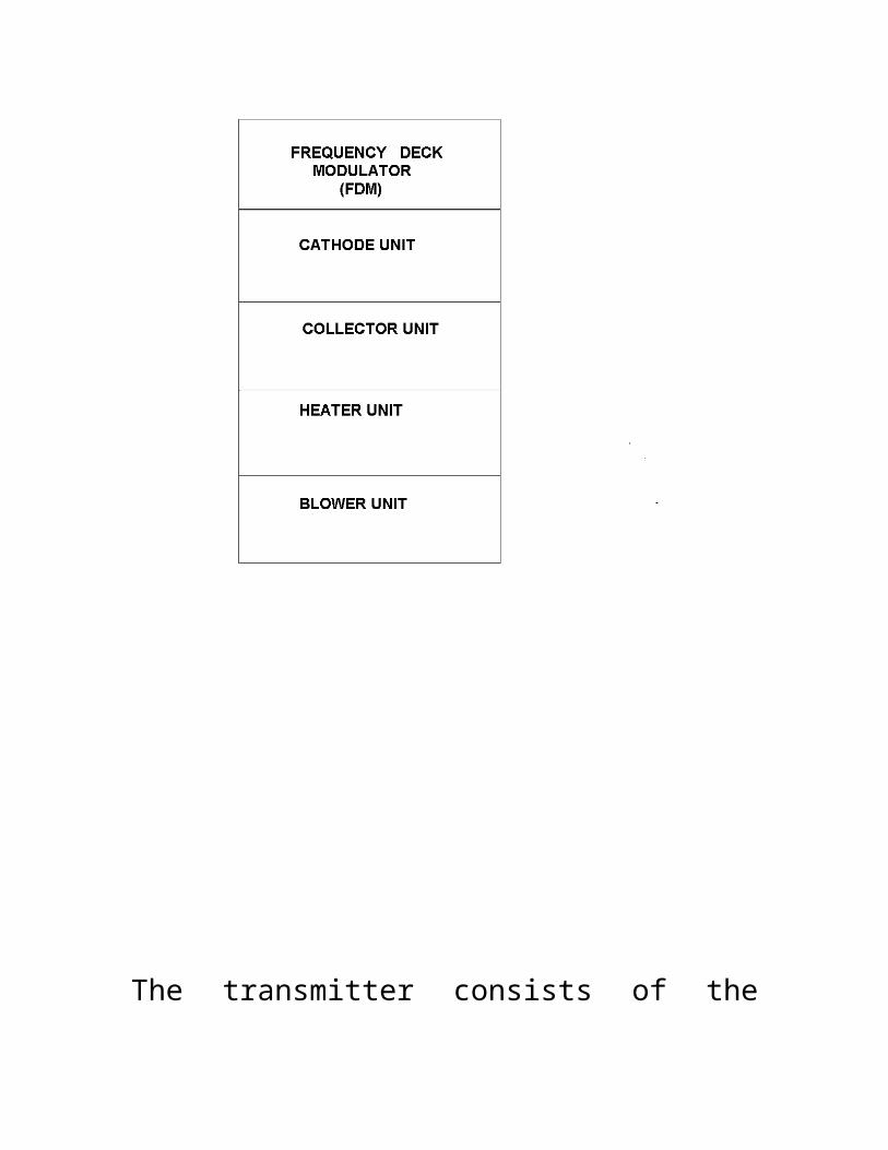
BLOCK DIAGRAM OF HIGH VOLTAGE RACK

The transmitter consists of the following racks:
HIGH VOLTAGE RACK: It consists of FDM, cathode and
collector assembly, heater and blower unit. The main function of the high
voltage rack is to provide high voltage power supply to cathode and collector
of the TWT. FDM is the most important component and it provides the
filament supply, grid bias and grid positive and negative supply to the TWT. It
also communicates with the CPC via optical links.
Cathode assembly provides the cathode supply and collector assembly
provides the collector supply to TWT. Heater unit is used for removing the
moisture within the rack. Blower unit provides cooling for cathode and
cathode assemblies.AC components probes in cathode and collector are used
to get the sample of output voltage and same is used to control the pulse
width of the inverter to achieve a regulation of .2%.
CONTROL RACK: The rack houses the inverter, control and protection
circuit, synoptic panel, control panel and monitoring panel.
MICROWAVE RACK: it consists of the low power amplifier, high power
TWT amplifier, ion pump supply, ferrite isolator, and high power dual direction
coupler and wave guide channel.. The microwave unit consists of the
following functional assemblies:
(a) Low power amplifier [RF drive unit]
(b) High power TWT amplifier
(c) RF Plumbing, Wave-guide switch & dummy load
(d) Solid state power amplifier (2 kW) for low power transmission
mode
(e) Protection, monitoring and diagnostic circuits
(f) Low voltage supply
(g) TWT ion pump supply
(h) Resistive TWT anode divider
(i) Microwave power measurement circuits
(j) Air cooling components
CONSRUCTION OF FDM (Floating Deck Modulator) ASSEMBLY:
The FDM assembly is on a space of 420 mm square with a depth of 700 mm.
the Floating Deck Modulator assembly houses FDM, carbon resistor block and
isolation transformer . the FDM assembly is covered on all sides by FRP
sheets and also floats on FRP mounts machined suitably for the purpose . The
FDM sub rack is at a distance of 390 mm from the front. The carbon resistors
are mounted on the front of the FDM rack. The isolation transformer is also
mounted in front of the carbon resistors. The voltmeters, hour meters are
fixed on to the front panel of FDM assembly.
The FDM assembly is being locally cooled by fans housed inside. The cooling
of entire sub assembly is taken care by mounting blowers at the rear end of
the compartment.
FDM consists of the following:
1. Filament supply and the timer card to generate filament supply for TWT
using fly – back converter.
2. Grid positive and grid negative supply card to generate grid bias and grid
positive supply.
3. Switch card to switch TWT between + 870 V and – 600 V.
4. LVPSU to generate all low voltage power supplies like + 15 V, + 5 V and +
24 V.
5. FDM transformer.
FUNCTIONS OF FDM:
1. Generates filament supply for TWT with surge current protection.
2. Generates grid bias and the grid positive supplies.
3. Provides switching function. (Switching of TWT grid as per pulse width and
the PRF requirement.)
4. Communication to CPC on optical link.
All the circuitry necessary to achieve the following functions is floating at the
cathode potential of – 45 V DC and needs special consideration in
engineering. All circuits are housed inside an equipotential surface.
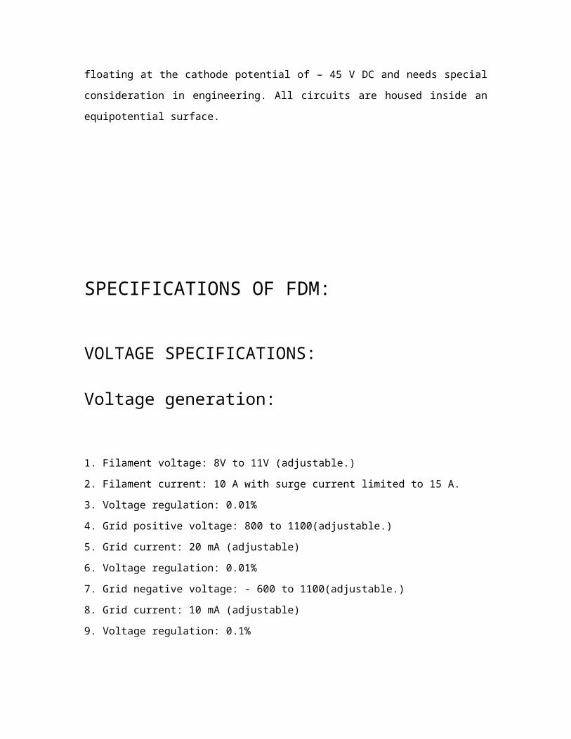
SPECIFICATIONS OF FDM:
VOLTAGE SPECIFICATIONS:
Voltage generation:
1. Filament voltage: 8V to 11V (adjustable.)
2. Filament current: 10 A with surge current limited to 15 A.
3. Voltage regulation: 0.01%
4. Grid positive voltage: 800 to 1100(adjustable.)
5. Grid current: 20 mA (adjustable)
6. Voltage regulation: 0.01%
7. Grid negative voltage: - 600 to 1100(adjustable.)
8. Grid current: 10 mA (adjustable)
9. Voltage regulation: 0.1%
Switch specifications:1) Switch output: - 800 to 1100 pulse.
2) Pulse width: 50, 25, 4 microseconds.
3) PRF: .5, 1, 4 (KHz)
4) Pulse rise time: < 0.5 microsecs. (The time taken by pulse to rise)
5) Pulse fall time : < 0.5 microsecs. (The time taken by pulse to fall.)
6) Pulse jitter: < 10 nsec.
7) Drop on the top of pulse :< 1V for 25 microsecs.

PROTECTIONS OF FDM:
1. Pulse width / PRF PROTECTION.
2. Short circuit protection.
3. Overload protection
4. Voltage too high and too low (window) protection
5. Thermal protection.
DESCRIPTION OF VARIOUS CARDS USED IN FDM:
1) V TO F CARD: This card contains six V to F converter (AD 650), four of which are used to
convert the grid positive, grid negative, filament voltage and filament current
samples to corresponding frequencies. This consists of four optical
transmitters for converting electrical pulses into light signals, which are
transmitted to CPC (cathode protection card) by optical links and optical
receivers to convert light signals to electrical pulses.
2) FILAMENT SUPPLY AND TIMER CARD – 1
The filament supply is a - 10 V/ 10 A supply for TWT filament. It is a switched
mode power supply and topology followed is fly – back converter. The supply
operates at a frequency of 25 KHz and PWM scheme is followed for
regulation. The switching device is protected against over currents by pulse
to pulse current limiting using a current transformer and current limit
comparator of UC 1526.
The supply has electronic current limiting which limits the initial current the
TWT initial surge current to 15 A and operates in current control mode until
the filament warms up. It is also provided with hard current limiting by means
of a series limiting resistor which is bypassed by operating a relay after 5 min
from initial power on. The current control feature is available only when this
card is operated along with filament supply and timer card – 2 . the card also
generates 115 V DC / 2 A supply , which is used as input for filament and grid
fly back converter.
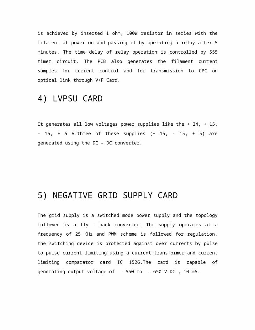
3) FILAMENT SUPPLY AND TIMER CARD – 2
This is responsible for the hard current limiting feature which is achieved by
inserted 1 ohm, 100W resistor in series with the filament at power on and
passing it by operating a relay after 5 minutes. The time delay of relay
operation is controlled by 555 timer circuit. The PCB also generates the
filament current samples for current control and for transmission to CPC on
optical link through V/F Card.
4) LVPSU CARD
It generates all low voltages power supplies like the + 24, + 15, - 15, + 5
V.three of these supplies (+ 15, - 15, + 5) are generated using the DC – DC
converter.
5) NEGATIVE GRID SUPPLY CARD
The grid supply is a switched mode power supply and the topology followed is
a fly - back converter. The supply operates at a frequency of 25 KHz and PWM
scheme is followed for regulation. the switching device is protected against
over currents by pulse to pulse current limiting using a current transformer
and current limiting comparator card IC 1526.The card is capable of
generating output voltage of - 550 to - 650 V DC , 10 mA.
6) POSITIVE GRID SUPPLY CARD
The grid supply is a switched mode power supply and the topology followed is
a fly - back converter. The supply operates at a frequency of 25 KHz and PWM

scheme is followed for regulation. the switching device is protected against
over currents by pulse to pulse current limiting using a current transformer
and current limiting comparator card IC 1526.The card is capable of
generating output voltage of +700 to +1000 V DC , 25 mA.
7) SWITCH CARD
It uses a fast high voltage switch of BHELKE make to switch the grid between
+ 870 V and – 600 V at required pulse width and PRF, based on input
command. The circuit configuration enables availability of continuous grid
– ve at TWT grid even if the bottom switch becomes faulty.
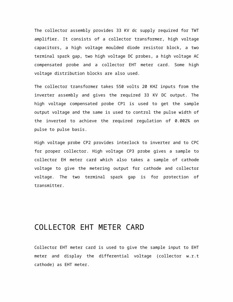
COLLECTOR ASSEMBLY
The collector assembly provides 33 KV dc supply required for TWT amplifier. It
consists of a collector transformer, high voltage capacitors, a high voltage
moulded diode resistor block, a two terminal spark gap, two high voltage DC
probes, a high voltage AC compensated probe and a collector EHT meter
card. Some high voltage distribution blocks are also used.
The collector transformer takes 550 volts 20 KHZ inputs from the inverter
assembly and gives the required 33 KV DC output. The high voltage
compensated probe CP1 is used to get the sample output voltage and the
same is used to control the pulse width of the inverted to achieve the
required regulation of 0.002% on pulse to pulse basis.
High voltage probe CP2 provides interlock to inverter and to CPC for proper

collector. High voltage CP3 probe gives a sample to collector EH meter card
which also takes a sample of cathode voltage to give the metering output for
cathode and collector voltage. The two terminal spark gap is for protection of
transmitter.
COLLECTOR EHT METER CARD
Collector EHT meter card is used to give the sample input to EHT meter and
display the differential voltage (collector w.r.t cathode) as EHT meter.
When +5 volts is applied at TP1, TP3 and TP4 (GND), output received at TP6
and TP7 (GND) is approximately 0 volts which is difference of TP1 and TP3
input voltage.
CATHODE ASSEMBLYThe cathode assembly provides - 45 KV DC supply required for the TWT
amplifier. It consists of a cathode transformer, a high wattage capacitor, a
high voltage diode block, resistor plate assembly, a three terminal spark gap,
two high voltage DC probes; a high voltage AC compensated probe, a
crowbar trigger unit and a droop circuit. Some high voltage distribution blocks
are also used.
The cathode transformer takes 550 volts; 20 KHz input from the inverter
assembly and give the required 45 KV DC output. The high voltage
compensated probe CP1 is used to get the sample output voltage and the
same is used to control the pulse width of the inverted to achieve the
required regulation of 0.002% on pulse to pulse basis.
High voltage probe CP2 provides interlock to inverter and to CPC for proper
collector. High voltage CP3 probe gives a sample to collector EHT meter card.

In case of fault CPC gives a control signal to the crowbar trigger unit, which
gives a 25 KHz pulse to the three terminal spark gap to switch off the high
voltage supply. The droop circuit is used for monitoring the droop voltage on the
monitoring panel, housed in control rack.
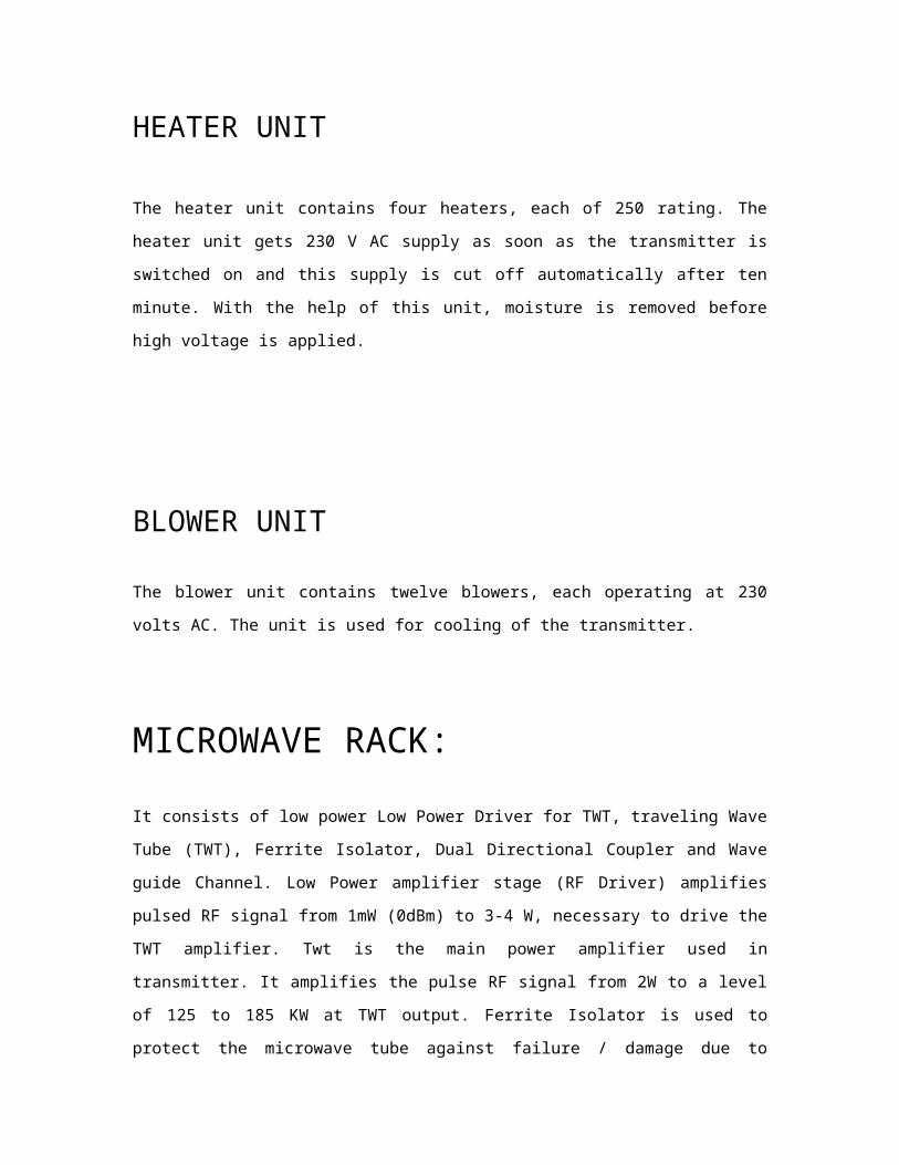
HEATER UNIT
The heater unit contains four heaters, each of 250 rating. The heater unit
gets 230 V AC supply as soon as the transmitter is switched on and this
supply is cut off automatically after ten minute. With the help of this unit,
moisture is removed before high voltage is applied.
BLOWER UNIT
The blower unit contains twelve blowers, each operating at 230 volts AC. The
unit is used for cooling of the transmitter.
MICROWAVE RACK:
It consists of low power Low Power Driver for TWT, traveling Wave Tube
(TWT), Ferrite Isolator, Dual Directional Coupler and Wave guide Channel. Low
Power amplifier stage (RF Driver) amplifies pulsed RF signal from 1mW
(0dBm) to 3-4 W, necessary to drive the TWT amplifier. Twt is the main power
amplifier used in transmitter. It amplifies the pulse RF signal from 2W to a
level of 125 to 185 KW at TWT output. Ferrite Isolator is used to protect the
microwave tube against failure / damage due to reflected power in case of
excess VSWR at Antenna input port. High Power Dual Directional Coupler
(DDC) is used for measuring the transmit power and reflected power. To
connect all components in the required form, flexible sections, E-bends, H-
bends and straight sections are used.
DESCRIPTION OF VARIOUS COMPONENTS
OF MICRO – WAVE RACK:
a) Low Power Driver for TWT (RF Driver)
Low Power amplifier stage (RF Driver) amplifies pulsed RF signal from 1mW
(0dBm) to 2 – 4 W, necessary to drive the TWT amplifier
b) High Power Microwave Stage
High Power RF stage consists of:
(a) Traveling Wave Tube (TWT)
(b) Ferrite Circulator
(c) Dual Directional Coupler (DDC)
(d) High Power dummy load
(e) Wave guide channel
(f) Wave guide switch

Traveling Wave Tube (TWT)TWT is the main power amplifier used in the transmitter. A coupled cavity
TWT type VTS – 5754 D2 is selected for this transmitter.
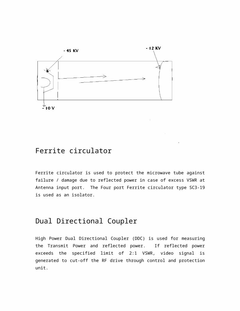
Diagram of TWT
Ferrite circulator
Ferrite circulator is used to protect the microwave tube against failure /
damage due to reflected power in case of excess VSWR at Antenna input
port. The Four port Ferrite circulator type SC3-19 is used as an isolator.
Dual Directional Coupler
High Power Dual Directional Coupler (DDC) is used for measuring the Transmit
Power and reflected power. If reflected power exceeds the specified limit of
2:1 VSWR, video signal is generated to cut-off the RF drive through control
and protection unit.
High power dummy load
High power dummy load is used to test the transmitter with out connecting
the antenna during standalone testing.
Wave-guide Channel
To connect all the components in the required form, flexible sections, E-
bends, H-bends and straight sections are used. Standard W/G sections are
being used for this purpose.
PEAK DETECTOR CARD
The function of this card is to detect the peak amplitude of the input signal

after amplifying it. The signal from crystal detector is given to the input of
this card, which is of the order of mill volts. This signal is amplified to about 7
times of the input. The peak is detected and its output is DC signal in the
order of volts.
The card has two peak detector channels.
When pulsed signal corresponding to the duty of transmitter is detected at
TP1 and TP2, AD847 OPAMP amplifies it to about 7 times. IC 139 is used as a
comparator.
Transistor Q1 is ON when output at U 2 - 1 is high. The DC output
corresponding to the peak amplitude of the input signal is measured at J 1 – 9
and GND.
The output RC time constant is adjusted such a way that the DC value holds
till the next pulse arrives. the time constant derived by R5 and C1 should
neither be too large, because in case of fault, where in the input will absent,
the output should die down within minimum time and nor should be too
small, that the output DC value droops down from the peak value at a much
higher rate, before the next pulse comes.
SIGNAL COMPILER CARD
Signal compiler card consist of two 25- pin Female Connector, six 9- Pin Male
Connector to provide one to one connection between Microwave Rack and
CPC.
Electronic Equipment Cabin (EEC)
Electronic Equipment Cabin (EEC) has the following subsystems
• Transmitter• Solid State Power Amplifier (SSPA)• Signal Data Processor (SDP)• Display Console• IFF• Master Control Unit (MCU)• Deployment Console Unit (DCU)• Dehydrator• Advance Land Navigation System (ALNS)• PC• Power Distribution Panel (PDP)• EMI Filter
Do’s & Don’ts
Radar positioning
1. Ground should be hard enough to sustain the pressure of elephant legs.
2. Ground slop should not be more than 4 degree for leveling.
3. Ideally terrain should be with zero obstruction upto 500 mtr radius. If this condition does not meet, at least area of interest should meet the requirement
4. Obstruction diagram for short range with the help of Theodolite and visibility diagram for long range to be done with the help of
map of concern location.
5. Radar should be 500 mtr away from high tension line.
PROJECTCENTRAL ACQUISITION RADAR
(CAR)
UNDER THE GUIDANCE OF: SUBMITTED BY:
TUSHAR AGARWAL
UPT NO. 634 ECE (070271111)
BEL, GHAZIABAD AKGEC, GHAZIABAD
PREFACE
This six week training program is a part of 4-year B.Tech. course. Practical industrial training mainly aims at making one aware of industrial environment, which means that one get to know the limitation, constraints and freedom under which an engineer works. One also gets an opportunity to see from close quarter that indicates management relation. This training mainly involves industrial and complete knowledge about designing, assembling and manufacturing of equipment.
During this period, the student gets the real experience for working in the industry environment. Most of the theoretical knowledge
that has been gained during the course of their studies is put to test here. Apart from this the student gets an opportunity to learn the latest technology, which immensely helps in them in building their career.
ACKNOWLEGEMENT
First of all I would like to express my gratitude to Mr._________________ , HR Department for arranging my training for the duration of six weeks. The training schedule prepared by them gave me an opportunity to have an insight of working methodology and procedures of BEL. I would like to thank department of HRD for the cooperation.
I offer my sincere gratitude to my guide ________________ for his continuous guidance and support. I would like to thank Mr .________________ and all the members of C.A.R radar assembly for helping me throughout my training.
My special thanks to whole staff of BEL for accepting me as a

trainee & helping me in Radar assembly. they proved themselves inspiring, helpful, productive and fruitful to me.
It will be in debt on my part if I forgot to give my thanks to all those visible and invisible hands that helped me throughout my training period.
TUSHAR AGARWAL
CERTIFICATE
This is to certify that Mr. TUSHAR AGARWAL, student of B.Tech (Electronics and Communication), AJAY KUMAR GARG ENGINEERING COLLEGE, GHAZIABAD successfully completed his six weeks training in BHARAT ELECTRONICS LIMITED, GHAZIABAD.
A project on “Central Acquisition Radar (3D-CAR)
Transmitter” was assigned to him. In this period he
worked hard and made valuable contribution in

developing the project. All his work is genuine and
original and was timely completed.