turf - tick turf tick sod harvester · e-mail [email protected] . 1 ... clipping machine on and off...
TRANSCRIPT
TURF - TICK
Original instructions
Turf Tick sod harvester
Version 2.3
March 2016
Turf Tick Products B.V.
Harmelerwaard 21
3481 LC Harmelen
Tel. +31 (0)30 666 13 48
Fax. +31 (0)30 666 13 40
E-mail [email protected]
1
According to NEN5509 – 1993
1. Introduction .................................................................................................................................... 2 2. Operation ........................................................................................................................................ 3 3. Composition of the machine.......................................................................................................... 4
3.1. Basic machine ............................................................................................................... 4
3.2. Cross conveyor .............................................................................................................. 4
3.3. Rotary brush .................................................................................................................. 4 3.4 Auto steer ......................................................................................................................................... 6 4. Use of the harvester ....................................................................................................................... 6 5. General Safety prescriptions......................................................................................................... 7
5.1. Safety prescriptions basis machine ............................................................................... 7
5.2. Safety instructions cross conveyor .............................................................................. 10
5.3. Safety instructions auto steer ...................................................................................... 10 6. Set-up preparation before starting ............................................................................................. 11
6.1. Basic Machine ............................................................................................................. 11 7. Use ................................................................................................................................................. 12
7.1. Controls....................................................................................................................... 12
7.1.1. Cutting the sod ..................................................................................................... 14
7.1.2. Adjusting the cutting thickness ............................................................................ 14
7.1.3. Speed main conveyor belts ................................................................................... 15
7.1.4. Speed cutting knife ............................................................................................... 15
7.1.5. Cross conveyor ..................................................................................................... 15
7.1.6. Rotary brush ......................................................................................................... 15
7.1.7. Auto steer ............................................................................................................. 16
7.2. Clipping machine on and off from the tractor ............................................................ 17
7.3. Change cutting blade .................................................................................................. 19
7.4. Settings and adjustments ............................................................................................. 20
7.4.1. Main conveyor belt speed ..................................................................................... 20
7.4.2. Cutter head ........................................................................................................... 23
7.4.3. Main frame ........................................................................................................... 27
7.4.4. Rollup system ....................................................................................................... 29
7.4.5. Trailer ................................................................................................................... 36 8. Maintenance ................................................................................................................................. 37
8.1. Maintenance schedule ................................................................................................. 37
8.2. Grease points survey ................................................................................................... 42 9. Diagrams ....................................................................................................................................... 52
9.1. Hydraulic system ......................................................................................................... 52
9.2. Electrical drawings ..................................................................................................... 53
2
1. Introduction
The Turf Tick Sod Harvester is an excellent machine that is produced with the utmost care.
This investment will bring to you the greatest benefits if you carefully read and follow the
instructions regarding safety, usage and maintenance as presented is this manual.
It is our urgent advice to read and study and follow the instructions in this manual.
The Turf Tick Harvester may not be operated by any person that has not
fully read and understood the instructions in this manual.
The Turf Tick Harvester is intended to be used by professional operators
only.
In case of any questions about the content or this manual, please inform us at the shortest
possible notice. We will react immediately in order to explain or otherwise contribute to safe
and proper operation or the machine.
Disclaimer!! Turf Tick Products B.V. cannot be held responsible for damage, direct or indirect, resulting
partly or whole from operation errors, lack or proper maintenance or unskilled use or any
other use of the machine than as described in this manual.
3
2. Operation
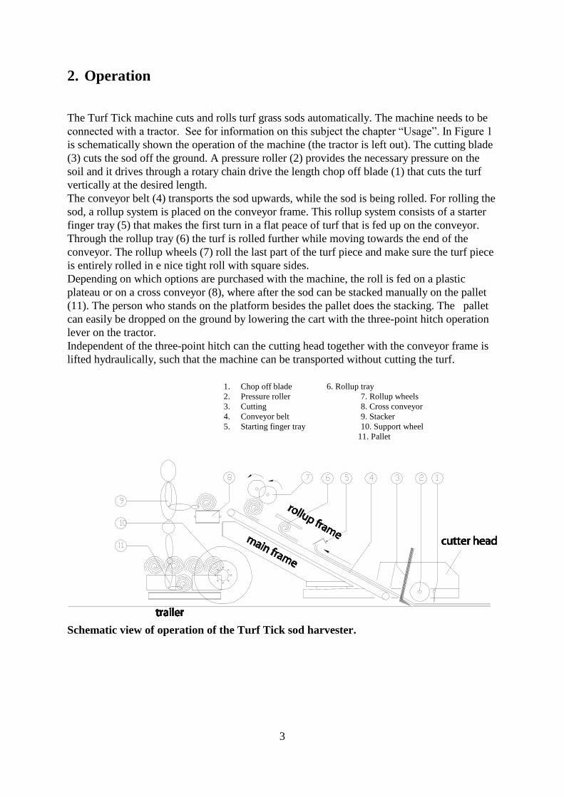
The Turf Tick machine cuts and rolls turf grass sods automatically. The machine needs to be
connected with a tractor. See for information on this subject the chapter “Usage”. In Figure 1
is schematically shown the operation of the machine (the tractor is left out). The cutting blade
(3) cuts the sod off the ground. A pressure roller (2) provides the necessary pressure on the
soil and it drives through a rotary chain drive the length chop off blade (1) that cuts the turf
vertically at the desired length.
The conveyor belt (4) transports the sod upwards, while the sod is being rolled. For rolling the
sod, a rollup system is placed on the conveyor frame. This rollup system consists of a starter
finger tray (5) that makes the first turn in a flat peace of turf that is fed up on the conveyor.
Through the rollup tray (6) the turf is rolled further while moving towards the end of the
conveyor. The rollup wheels (7) roll the last part of the turf piece and make sure the turf piece
is entirely rolled in e nice tight roll with square sides.
Depending on which options are purchased with the machine, the roll is fed on a plastic
plateau or on a cross conveyor (8), where after the sod can be stacked manually on the pallet
(11). The person who stands on the platform besides the pallet does the stacking. The pallet
can easily be dropped on the ground by lowering the cart with the three-point hitch operation
lever on the tractor.
Independent of the three-point hitch can the cutting head together with the conveyor frame is
lifted hydraulically, such that the machine can be transported without cutting the turf.
Schematic view of operation of the Turf Tick sod harvester.
1. Chop off blade 6. Rollup tray
2. Pressure roller 7. Rollup wheels
3. Cutting 8. Cross conveyor
4. Conveyor belt 9. Stacker
5. Starting finger tray 10. Support wheel
11. Pallet
4
3. Composition of the machine
The Turf Tick basic machine can be equipped with further options. The options can be
supplied directly with the original purchase of the machine or they can be purchased
separately in a later stage. The options are:
Auto steer
Cross conveyor
Rotary brush
Figure 1 shows a number of these components.
3.1. Basic machine
The following major components of the Turf Tick basis machine can be distinguished:
Cutting head:
- Cutting blade, driven by crankshaft
- Length chop off blade, driven by bottom roll using a chain and sprockets.
- Lifting arm mount, for lifting the machine for transport.
Basic frame:
- Conveyor belts, driven by a hydraulic motor using a chain and sprockets.
Rollup frame:
- Starter finger tray.
- Rollup tray.
- Rollup rubber wheels, driven by a chain drive.
Trailer:
- Platform for a person who is stacking the sods on the pallet.
- Pallet-forks with pallet
- Wheels
- 3-point hitch for tractor
3.2. Cross conveyor
It is possible to mount a cross conveyor near the end of the main conveyor frame, to
automatically transport the sods in a cross direction when they leave the main conveyor. The
cross conveyor is hydraulically driven.
3.3. Rotary brush
The rotary brush cleans during the cutting the next pass of the turf. It an inward position for
transportation and a working position where it is swung sideways out so that it is in the

5
position to sweep the edge of the turf field that is to be cut during the next pass of the
harvester.
6
3.4 Auto steer
With the optional auto steer unit it is possible to steer the tractor automatically alongside the
edge of the field, following the perfect line. The Autosteer is an electro-hydraulic system. It
consists of:
A steering shoe with sensor, which follows the edge of the turf.
A sensor mounted to the existing steering wheels of the tractor, to measure the steering
angle.
A control unit which controls the steering direction for the wheels, based on the
signals from both the steering shoe and wheels. This control unit consists of:
-an electrical part
-a hydraulic part.
A more extended description of the auto steer system can be found in the separate user manual
that comes with the auto steer system. See for further details this separate auto steer manual.
4. Use of the harvester
The Turf Tick sod harvester is specially developed for:
- The cutting and automatic rolling of turf on levelled area at a speed of max 5 kilometers in
1 hour.
- In use the machine needs to be connected with a tractor that is suitable and fit for that
purpose. Read for information on this subject also the chapter “Setting up for use”
- For taking with it in the field only one pallet with turf stacked on it. The absolute
maximum weight of the pallet with turf is 1500 kg.
- The Turf Tick sod harvester is not approved and designed for driving on the public
roads When transportation over public roads is necessary, the machine needs to adapted
and checked to make sure that that it fulfils to all specific national or local prescriptions.
The machine is not developed for transport of people. Only on the platform (see chapter
“operation “) it is permitted for one experienced person to stand and work.
During transportation it is not permitted for a person to be transported with the machine,
beside the tractor driver, who is to be seated on the tractor seat
Use the Turf Tick only for the purpose it is developed.
7
5. General Safety prescriptions
Read following Safety prescriptions entirely before starting
operation of the machine.
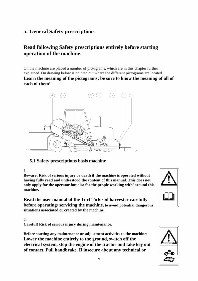
On the machine are placed a number of pictograms, which are in this chapter further
explained. On drawing below is pointed out where the different pictograms are located.
Learn the meaning of the pictograms; be sure to know the meaning of all of
each of them!
5.1. Safety prescriptions basis machine
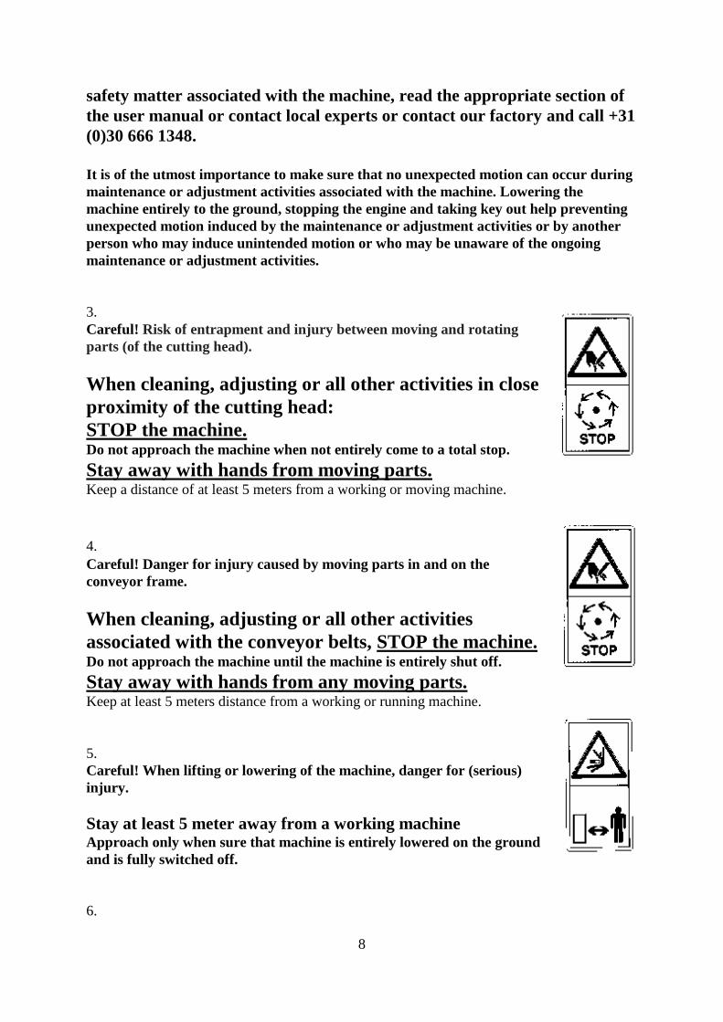
1.
Beware: Risk of serious injury or death if the machine is operated without
having fully read and understood the content of this manual. This does not
only apply for the operator but also for the people working with/ around this
machine.
Read the user manual of the Turf Tick sod harvester carefully
before operating/ servicing the machine, to avoid potential dangerous
situations associated or created by the machine.
2.
Careful! Risk of serious injury during maintenance.
Before starting any maintenance or adjustment activities to the machine:
Lower the machine entirely to the ground, switch off the
electrical system, stop the engine of the tractor and take key out
of contact. Pull handbrake. If insecure about any technical or
8
safety matter associated with the machine, read the appropriate section of
the user manual or contact local experts or contact our factory and call +31
(0)30 666 1348.
It is of the utmost importance to make sure that no unexpected motion can occur during
maintenance or adjustment activities associated with the machine. Lowering the
machine entirely to the ground, stopping the engine and taking key out help preventing
unexpected motion induced by the maintenance or adjustment activities or by another
person who may induce unintended motion or who may be unaware of the ongoing
maintenance or adjustment activities.
3.
Careful! Risk of entrapment and injury between moving and rotating
parts (of the cutting head).
When cleaning, adjusting or all other activities in close
proximity of the cutting head:
STOP the machine. Do not approach the machine when not entirely come to a total stop.
Stay away with hands from moving parts. Keep a distance of at least 5 meters from a working or moving machine.
4. Careful! Danger for injury caused by moving parts in and on the
conveyor frame.
When cleaning, adjusting or all other activities
associated with the conveyor belts, STOP the machine. Do not approach the machine until the machine is entirely shut off.
Stay away with hands from any moving parts. Keep at least 5 meters distance from a working or running machine.
5.
Careful! When lifting or lowering of the machine, danger for (serious)
injury.
Stay at least 5 meter away from a working machine Approach only when sure that machine is entirely lowered on the ground
and is fully switched off.
6.
9
Take care! Danger for injury when trapped if covers are removed
Make sure that all covers and shields in all instances are mounted
100% correctly when during use of the machine. Only in case of maintenance it is allowed to remove the any covers or shields. See for this
chapter maintenance.
Check on replacement of all covers and shields after maintenance.
7.
Careful! Danger for injury, because of hydraulic system.
The hydraulic system operates with high pressure.
Before working at the system make sure that de system is no pressure at all. Highly
pressurized oil (up to 160 bar) passes easily through clothing and infringes the skin. This can
result in very serious injury to the skin. Highly pressurized oil can easily cause blood
poisoning.
8.
Careful! Danger during connecting and disconnecting the machine to the tractor.
Take care that during connecting and disconnecting the machine not a person is entirely or
with any limb between the tractor and the machine.
For correctly connecting and disconnecting the machine to the tractor, read carefully the
chapter “Use” of this user manual.
9.
Careful! Danger while standing and working on the stacking platform besides the pallet.
In order to work safely on the stacker platform, following safety rules need be practiced.
- Drive while cutting the turf never faster than walking speed.
- Avoid sudden movement of the harvester. Do not start driving abruptly and avoid abrupt
stop operations. Before starting movement of the tractor, always make sure that the
“stacker” is stable at his position and is aware that movement will start.
- When driving the machine while not cutting it is strongly advised that the stacker is not on
the platform. In case of necessity for the stacker to be on the platform during transport of
the machine, make sure that the stacker holds with his hands a stable support at the
machine. Make sure that the stacker will not approach with his hands or limb any part of
the machine that can start moving unexpectedly by any action or possible operator error.
The stacker can stabilize his position by holding the end bar of the rollup frame. See also
chapter “Operation”. Remember that being on the platform during transport will remain a
possibly hazardous activity that is to be handled with utmost care and may not be a regular
activity. For inexperienced persons or with an inexperienced tractor driver it is absolutely
forbidden.
- Do not drive backward with the stacker standing on the platform. Make it a 100% habit of
waiting with driving backwards until the stacker has a safe distance from the path of travel
of the machine.
10
10.
Watch out! Danger if not passing through safety instructions to any new operator or
stacker.
People can seriously hurt themselves if people do not pass through the information about
safety instructions. Make sure new users of the machine are fully informed about the
instructions and dangers of the machine.
5.2. Safety instructions cross conveyor
11.
Watch out!
People can seriously hurt themselves if the protection covers of the cross conveyor are not
mounted. Make sure the protection covers are always mounted before using the machine.
5.3. Safety instructions auto steer
12.
Watch out! Danger if disturbance auto steer.
People can seriously hurt themselves when the auto steer system steers the tractor not
properly. Therefore, never drive faster than 5 km/h with auto steer switched on and stop the
tractor immediately if failure happens.
13.
Watch out! Danger if unintentionally switching on auto steer.
People can seriously hurt themselves when you unintentionally switch on the auto steer.
For instance if you drive on a public road. Therefore only switch on the auto steer if you start
cutting grass. Before lifting the machine you have to switch off the auto steer.
14.
Watch out! Danger using automatic clutch by insufficient sight.
People can seriously hurt themselves when you can’t see the person on the back of the
machine and still want to use the automatic clutch. If the sight is insufficient, don’t drive the
machine.
11
6. Set-up preparation before starting
6.1. Basic Machine
The Turf Tick machine is assembled in three main parts.
The trailer (parts book 101-52). This one is mounted on the 3-point hitch at the back
of the tractor.
The sod harvester, existing off cutter head, mainframe and rolling up frame. This one
is connected to the trailer and on the bottom side of the tractor with a special mounting
frame.
Mounting frame, (parts book 100-50). This one needs to be made at size and mounted
at the “belly” of the tractor. The mainframe of the cutting machine is mounted on this.
An employee of Turf Tick Products B.V is making the sod harvester at size in six steps.
These steps are:
1. Connection of the trailer to the three-point hitch of the tractor.
2. Connection of the sod harvester to the trailer with a special connecting frame (parts
book 101-52-17 en 101-52-16).
3. Lengthen the mounting frame, such that the sod harvester is at the right distance of the
tractor.
4. Connection of the hydraulic tubes.
5. Connection of the electric parts.
6. Adjustment of the sod harvester to your specific needs en circumstances (referred in
chapter “Settings and adjustments”.
12
7. Use
Before using the machine, it needs to be set upped (referred in chapter Set up preparation for
starting), safety prescriptions completely read and the machine set upped and adjusted
(referred in chapter “Settings and adjustments”)
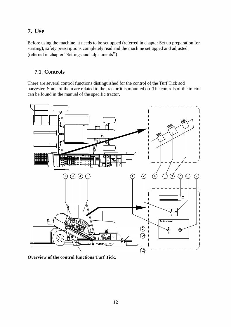
7.1. Controls
There are several control functions distinguished for the control of the Turf Tick sod
harvester. Some of them are related to the tractor it is mounted on. The controls of the tractor
can be found in the manual of the specific tractor.
Overview of the control functions Turf Tick.
13
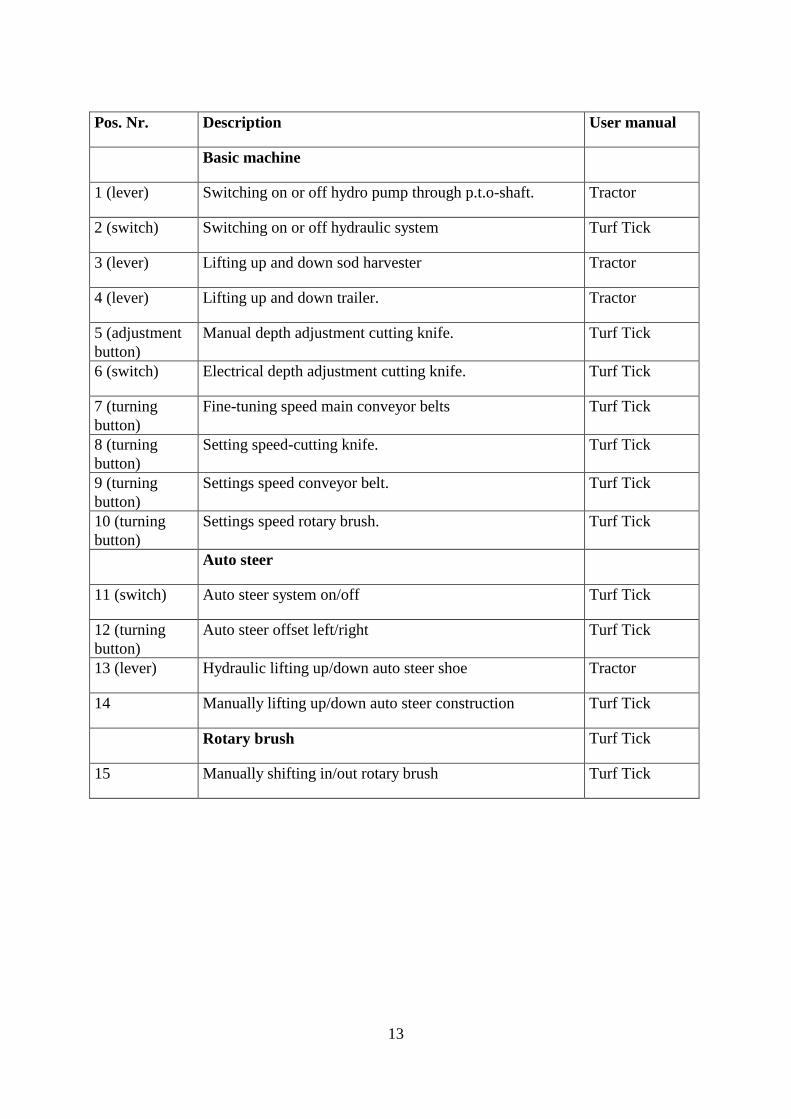
Pos. Nr. Description User manual
Basic machine
1 (lever) Switching on or off hydro pump through p.t.o-shaft. Tractor
2 (switch) Switching on or off hydraulic system Turf Tick
3 (lever) Lifting up and down sod harvester Tractor
4 (lever) Lifting up and down trailer. Tractor
5 (adjustment
button)
Manual depth adjustment cutting knife. Turf Tick
6 (switch) Electrical depth adjustment cutting knife. Turf Tick
7 (turning
button)
Fine-tuning speed main conveyor belts Turf Tick
8 (turning
button)
Setting speed-cutting knife. Turf Tick
9 (turning
button)
Settings speed conveyor belt. Turf Tick
10 (turning
button)
Settings speed rotary brush. Turf Tick
Auto steer
11 (switch) Auto steer system on/off Turf Tick
12 (turning
button)
Auto steer offset left/right Turf Tick
13 (lever) Hydraulic lifting up/down auto steer shoe Tractor
14 Manually lifting up/down auto steer construction Turf Tick
Rotary brush Turf Tick
15 Manually shifting in/out rotary brush Turf Tick
14
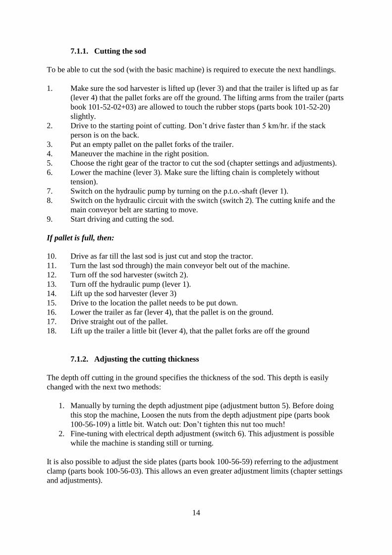
7.1.1. Cutting the sod
To be able to cut the sod (with the basic machine) is required to execute the next handlings.
1. Make sure the sod harvester is lifted up (lever 3) and that the trailer is lifted up as far
(lever 4) that the pallet forks are off the ground. The lifting arms from the trailer (parts
book 101-52-02+03) are allowed to touch the rubber stops (parts book 101-52-20)
slightly.
2. Drive to the starting point of cutting. Don’t drive faster than 5 km/hr. if the stack
person is on the back.
3. Put an empty pallet on the pallet forks of the trailer.
4. Maneuver the machine in the right position.
5. Choose the right gear of the tractor to cut the sod (chapter settings and adjustments).
6. Lower the machine (lever 3). Make sure the lifting chain is completely without
tension).
7. Switch on the hydraulic pump by turning on the p.t.o.-shaft (lever 1).
8. Switch on the hydraulic circuit with the switch (switch 2). The cutting knife and the
main conveyor belt are starting to move.
9. Start driving and cutting the sod.
If pallet is full, then:
10. Drive as far till the last sod is just cut and stop the tractor.
11. Turn the last sod through) the main conveyor belt out of the machine.
12. Turn off the sod harvester (switch 2).
13. Turn off the hydraulic pump (lever 1).
14. Lift up the sod harvester (lever 3)
15. Drive to the location the pallet needs to be put down.
16. Lower the trailer as far (lever 4), that the pallet is on the ground.
17. Drive straight out of the pallet.
18. Lift up the trailer a little bit (lever 4), that the pallet forks are off the ground
7.1.2. Adjusting the cutting thickness
The depth off cutting in the ground specifies the thickness of the sod. This depth is easily
changed with the next two methods:
1. Manually by turning the depth adjustment pipe (adjustment button 5). Before doing
this stop the machine, Loosen the nuts from the depth adjustment pipe (parts book
100-56-109) a little bit. Watch out: Don’t tighten this nut too much!
2. Fine-tuning with electrical depth adjustment (switch 6). This adjustment is possible
while the machine is standing still or turning.
It is also possible to adjust the side plates (parts book 100-56-59) referring to the adjustment
clamp (parts book 100-56-03). This allows an even greater adjustment limits (chapter settings
and adjustments).
15
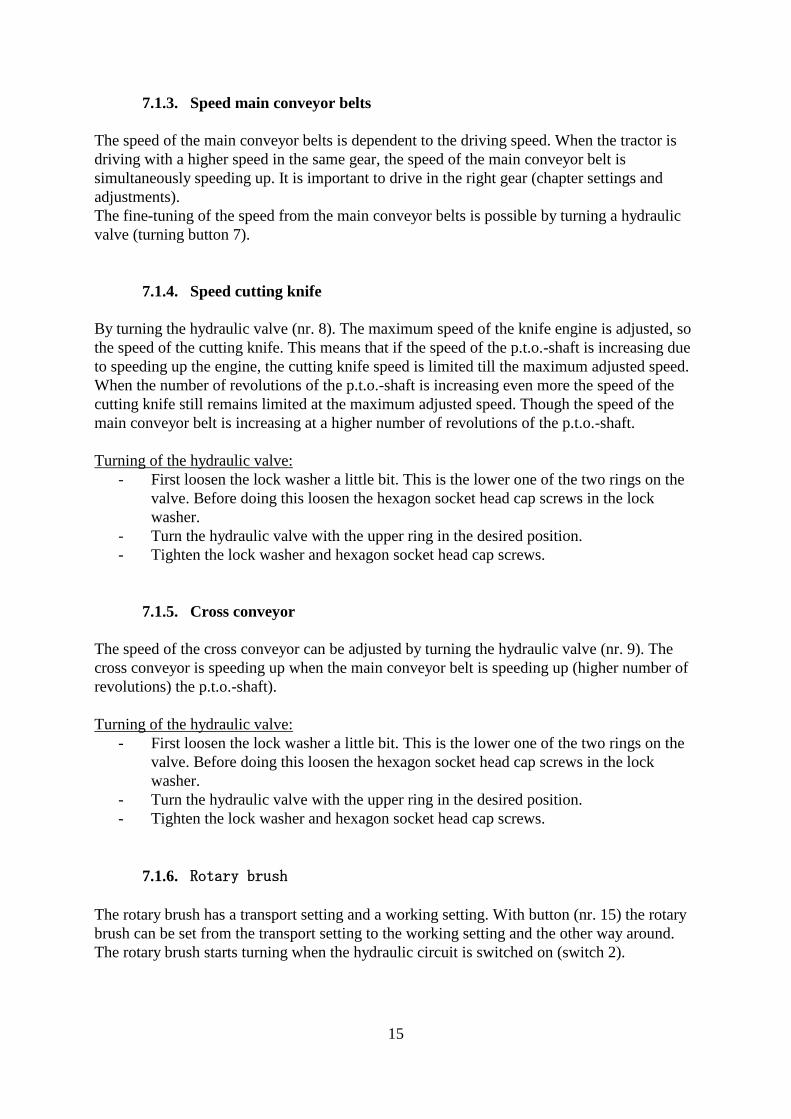
7.1.3. Speed main conveyor belts
The speed of the main conveyor belts is dependent to the driving speed. When the tractor is
driving with a higher speed in the same gear, the speed of the main conveyor belt is
simultaneously speeding up. It is important to drive in the right gear (chapter settings and
adjustments).
The fine-tuning of the speed from the main conveyor belts is possible by turning a hydraulic
valve (turning button 7).
7.1.4. Speed cutting knife
By turning the hydraulic valve (nr. 8). The maximum speed of the knife engine is adjusted, so
the speed of the cutting knife. This means that if the speed of the p.t.o.-shaft is increasing due
to speeding up the engine, the cutting knife speed is limited till the maximum adjusted speed.
When the number of revolutions of the p.t.o.-shaft is increasing even more the speed of the
cutting knife still remains limited at the maximum adjusted speed. Though the speed of the
main conveyor belt is increasing at a higher number of revolutions of the p.t.o.-shaft.
Turning of the hydraulic valve:
- First loosen the lock washer a little bit. This is the lower one of the two rings on the
valve. Before doing this loosen the hexagon socket head cap screws in the lock
washer.
- Turn the hydraulic valve with the upper ring in the desired position.
- Tighten the lock washer and hexagon socket head cap screws.
7.1.5. Cross conveyor
The speed of the cross conveyor can be adjusted by turning the hydraulic valve (nr. 9). The
cross conveyor is speeding up when the main conveyor belt is speeding up (higher number of
revolutions) the p.t.o.-shaft).
Turning of the hydraulic valve:
- First loosen the lock washer a little bit. This is the lower one of the two rings on the
valve. Before doing this loosen the hexagon socket head cap screws in the lock
washer.
- Turn the hydraulic valve with the upper ring in the desired position.
- Tighten the lock washer and hexagon socket head cap screws.
7.1.6. Rotary brush
The rotary brush has a transport setting and a working setting. With button (nr. 15) the rotary
brush can be set from the transport setting to the working setting and the other way around.
The rotary brush starts turning when the hydraulic circuit is switched on (switch 2).
16
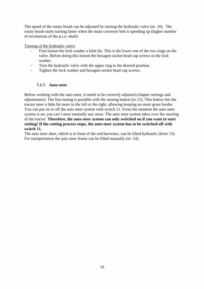
The speed of the rotary brush can be adjusted by turning the hydraulic valve (nr. 10). The
rotary brush starts turning faster when the main conveyor belt is speeding up (higher number
of revolutions of the p.t.o.-shaft)
Turning of the hydraulic valve:
- First loosen the lock washer a little bit. This is the lower one of the two rings on the
valve. Before doing this loosen the hexagon socket head cap screws in the lock
washer.
- Turn the hydraulic valve with the upper ring in the desired position.
- Tighten the lock washer and hexagon socket head cap screws.
7.1.7. Auto steer
Before working with the auto steer, it needs to be correctly adjusted (chapter settings and
adjustments). The fine-tuning is possible with the turning button (nr.12). This button lets the
tractor steer a little bit more to the left or the right, allowing keeping no more grass border.
You can put on or off the auto steer system with switch 11. From the moment the auto steer
system is on, you can’t steer manually any more. The auto steer system takes over the steering
of the tractor. Therefore, the auto steer system can only switched on if you want to start
cutting! If the cutting process stops, the auto steer system has to be switched off with
switch 11.
The auto steer shoe, which is in front of the sod harvester, can be lifted hydraulic (lever 13).
For transportation the auto steer frame can be lifted manually (nr. 14).
17
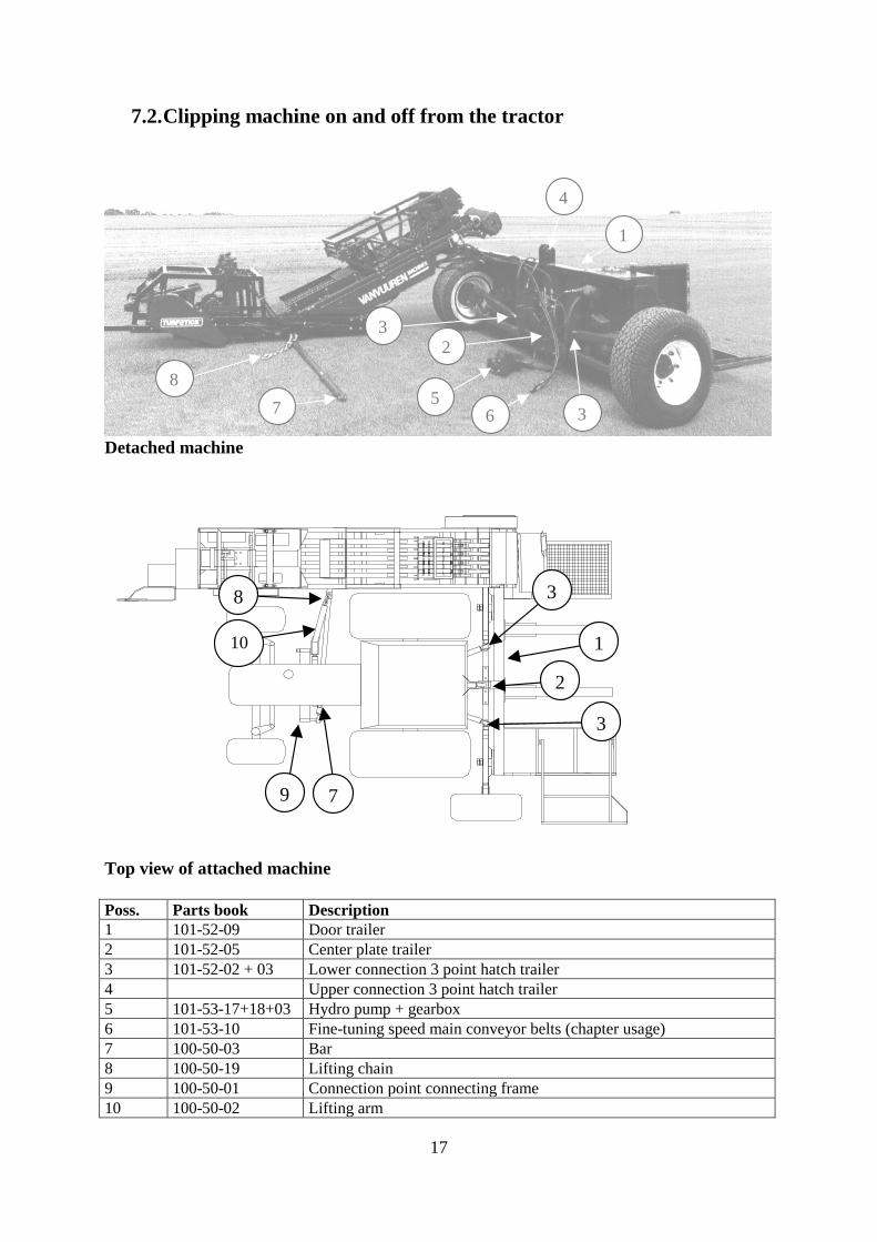
7.2. Clipping machine on and off from the tractor
4
1
365
23
7
8
Detached machine
7
10
0
8
9
3
1
2
3
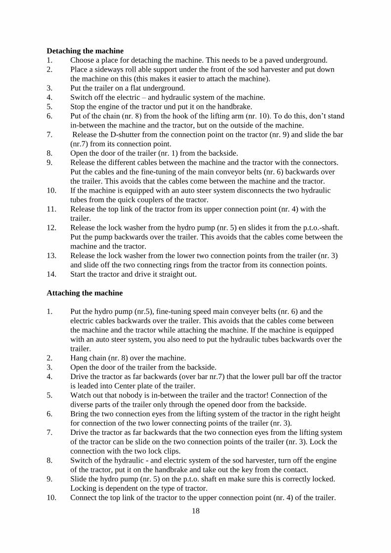
Top view of attached machine
Poss. Parts book Description
1 101-52-09 Door trailer
2 101-52-05 Center plate trailer
3 101-52-02 + 03 Lower connection 3 point hatch trailer
4 Upper connection 3 point hatch trailer
5 101-53-17+18+03 Hydro pump + gearbox
6 101-53-10 Fine-tuning speed main conveyor belts (chapter usage)
7 100-50-03 Bar
8 100-50-19 Lifting chain
9 100-50-01 Connection point connecting frame
10 100-50-02 Lifting arm
18
Detaching the machine
1. Choose a place for detaching the machine. This needs to be a paved underground.
2. Place a sideways roll able support under the front of the sod harvester and put down
the machine on this (this makes it easier to attach the machine).
3. Put the trailer on a flat underground.
4. Switch off the electric – and hydraulic system of the machine.
5. Stop the engine of the tractor und put it on the handbrake.
6. Put of the chain (nr. 8) from the hook of the lifting arm (nr. 10). To do this, don’t stand
in-between the machine and the tractor, but on the outside of the machine.
7. Release the D-shutter from the connection point on the tractor (nr. 9) and slide the bar
(nr.7) from its connection point.
8. Open the door of the trailer (nr. 1) from the backside.
9. Release the different cables between the machine and the tractor with the connectors.
Put the cables and the fine-tuning of the main conveyor belts (nr. 6) backwards over
the trailer. This avoids that the cables come between the machine and the tractor.
10. If the machine is equipped with an auto steer system disconnects the two hydraulic
tubes from the quick couplers of the tractor.
11. Release the top link of the tractor from its upper connection point (nr. 4) with the
trailer.
12. Release the lock washer from the hydro pump (nr. 5) en slides it from the p.t.o.-shaft.
Put the pump backwards over the trailer. This avoids that the cables come between the
machine and the tractor.
13. Release the lock washer from the lower two connection points from the trailer (nr. 3)
and slide off the two connecting rings from the tractor from its connection points.
14. Start the tractor and drive it straight out.
Attaching the machine
1. Put the hydro pump (nr.5), fine-tuning speed main conveyer belts (nr. 6) and the
electric cables backwards over the trailer. This avoids that the cables come between
the machine and the tractor while attaching the machine. If the machine is equipped
with an auto steer system, you also need to put the hydraulic tubes backwards over the
trailer.
2. Hang chain (nr. 8) over the machine.
3. Open the door of the trailer from the backside.
4. Drive the tractor as far backwards (over bar nr.7) that the lower pull bar off the tractor
is leaded into Center plate of the trailer.
5. Watch out that nobody is in-between the trailer and the tractor! Connection of the
diverse parts of the trailer only through the opened door from the backside.
6. Bring the two connection eyes from the lifting system of the tractor in the right height
for connection of the two lower connecting points of the trailer (nr. 3).
7. Drive the tractor as far backwards that the two connection eyes from the lifting system
of the tractor can be slide on the two connection points of the trailer (nr. 3). Lock the
connection with the two lock clips.
8. Switch of the hydraulic - and electric system of the sod harvester, turn off the engine
of the tractor, put it on the handbrake and take out the key from the contact.
9. Slide the hydro pump (nr. 5) on the p.t.o. shaft en make sure this is correctly locked.
Locking is dependent on the type of tractor.
10. Connect the top link of the tractor to the upper connection point (nr. 4) of the trailer.
19
11. If the machine is equipped with an auto steer system, put the two hydraulic tubes in the
quick couplers of the tractor.
12. Connect the different electrical cables of the machine with the cables of the tractor.
13. Slide bar (nr. 7) on the connection point of the tractor (nr. 9) en lock this with the lock
clip.
14. Put the lifting chain (nr. 8) on the lifting arm (nr.10). Don’t stand in-between the
machine and the tractor, but stand on the outside of the machine.
7.3. Change cutting blade
The cutting blade of the machine is heavily loaded and for that reason in needs to be changed
regularly. The cutting blade needs to be changed if:
- The cutting blade is that much blunt that it doesn’t cut properly any more. It starts
bending out or even pushing itself out of the ground.
- The cutting blade is unevenly worn-out, that the sod isn’t of a constant thickness
anymore. One side is thicker than the other.
Procedure changing the cutting blade:
1. Unfold the support leg of the machine (front side of the machine). Put a support block
under the machine if it is equipped with an auto steer system.
2. Lower the machine on the support leg or support block.
3. Switch off the hydraulic – and electrical system of the machine, turn off the engine, put it
on the handbrake and get the key out of the contact.
4. Change the cutting blade. Watch out: Tighten the bolts as much as possible and remind
toothed lock washers to avoid loosening.
20
7.4. Settings and adjustments
7.4.1. Main conveyor belt speed
For an optimal performance of the Turf Tick sod harvester it is of great importance that the
speed of the main conveyor belts corresponding to the driving speed is adjusted correctly. The
speed of the main conveyor belts is associated with the driving speed of the tractor (through
the p.t.o. shaft). So when the tractor is driving faster (in the same gear), the speed of the main
conveyor belts start to speed up the same. The speed of the main conveyor belts stays right
according to the driving speed.
Influence factors on the speed of the main conveyor belts.
The speed of the main conveyor belts according to the driving speed of the tractor is specified
by:
The tractor:
- The gear that is driven in.
- Choice of p.t.o. shaft gear (1 or 2 possibilities dependent on the type of tractor)
The sod harvester:
- Gear wheel unit hydraulic pump (parts book 101-53-18)
- Pump produce hydraulic pump (parts book 101-52-17)
- Slag volume Hydraulic engine main conveyor belts.
- Gear wheel relations drive main conveyor belts.
- Fine-tuning main conveyor belts (parts book 101-53-10, chapter usage)
The sod harvester is standard delivered with specific settings (gear wheel unit, pump, etc.)
This means that the tractor needs to be adapted to gain the right speed of the main conveyor
belts in relation to the driving speed. Choose the right driving – and p.t.o. shaft gear.
If you want to use a different driving gear, because you want to cut faster or slower, the sod
harvester needs to be adjusted different. This is easily possible by changing the gear wheel
relation drive main conveyor belts.
The right speed of the main conveyor belts in relation to the driving speed.
The goal of a right adjustment of the speed from the main conveyor belts is that it needs to be
a little bit faster than the driving speed of the tractor while cutting the sods. If the speed is
lower than the driving speed the sods are pushed up while if the speed is too fast, the sods are
torn apart.
21
1
A
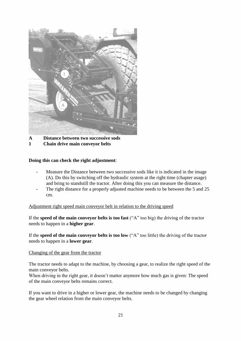
A Distance between two successive sods
1 Chain drive main conveyor belts
Doing this can check the right adjustment:
- Measure the Distance between two successive sods like it is indicated in the image
(A). Do this by switching off the hydraulic system at the right time (chapter usage)
and bring to standstill the tractor. After doing this you can measure the distance.
- The right distance for a properly adjusted machine needs to be between the 5 and 25
cm.
Adjustment right speed main conveyor belt in relation to the driving speed
If the speed of the main conveyor belts is too fast (“A” too big) the driving of the tractor
needs to happen in a higher gear.
If the speed of the main conveyor belts is too low (“A” too little) the driving of the tractor
needs to happen in a lower gear.
Changing of the gear from the tractor
The tractor needs to adapt to the machine, by choosing a gear, to realize the right speed of the
main conveyor belts.
When driving in the right gear, it doesn’t matter anymore how much gas is given: The speed
of the main conveyor belts remains correct.
If you want to drive in a higher or lower gear, the machine needs to be changed by changing
the gear wheel relation from the main conveyor belts.
22
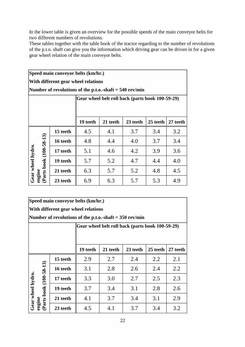
In the lower table is given an overview for the possible speeds of the main conveyor belts for
two different numbers of revolutions.
These tables together with the table book of the tractor regarding to the number of revolutions
of the p.t.o. shaft can give you the information which driving gear can be driven in for a given
gear wheel relation of the main conveyor belts.
Speed main conveyor belts (km/hr.)
With different gear wheel relations
Number of revolutions of the p.t.o.-shaft = 540 rev/min
Gear wheel belt roll back (parts book 100-59-29)
19 teeth 21 teeth 23 teeth 25 teeth 27 teeth
Gea
r w
hee
l h
yd
ro.
engin
e
(Part
s b
ook
(100-5
8-1
3) 15 teeth 4.5 4.1 3.7 3.4 3.2
16 teeth 4.8 4.4 4.0 3.7 3.4
17 teeth 5.1 4.6 4.2 3.9 3.6
19 teeth 5.7 5.2 4.7 4.4 4.0
21 teeth 6.3 5.7 5.2 4.8 4.5
23 teeth 6.9 6.3 5.7 5.3 4.9
Speed main conveyor belts (km/hr.)
With different gear wheel relations
Number of revolutions of the p.t.o.-shaft = 350 rev/min
Gear wheel belt roll back (parts book 100-59-29)
19 teeth 21 teeth 23 teeth 25 teeth 27 teeth
Gea
r w
hee
l h
yd
ro.
engin
e
(Part
s b
ook
(100-5
8-1
3) 15 teeth 2.9 2.7 2.4 2.2 2.1
16 teeth 3.1 2.8 2.6 2.4 2.2
17 teeth 3.3 3.0 2.7 2.5 2.3
19 teeth 3.7 3.4 3.1 2.8 2.6
21 teeth 4.1 3.7 3.4 3.1 2.9
23 teeth 4.5 4.1 3.7 3.4 3.2
23
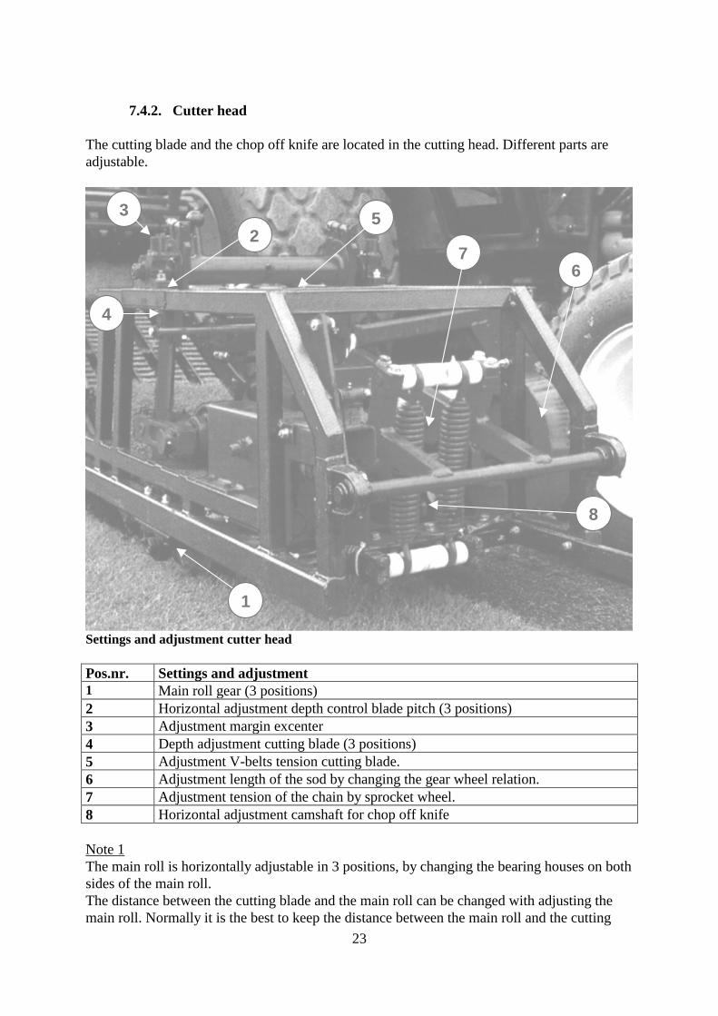
7.4.2. Cutter head
The cutting blade and the chop off knife are located in the cutting head. Different parts are
adjustable.
2
1
3
4
6
8
7
5
Settings and adjustment cutter head
Pos.nr. Settings and adjustment
1 Main roll gear (3 positions)
2 Horizontal adjustment depth control blade pitch (3 positions)
3 Adjustment margin excenter
4 Depth adjustment cutting blade (3 positions)
5 Adjustment V-belts tension cutting blade.
6 Adjustment length of the sod by changing the gear wheel relation.
7 Adjustment tension of the chain by sprocket wheel.
8 Horizontal adjustment camshaft for chop off knife
Note 1
The main roll is horizontally adjustable in 3 positions, by changing the bearing houses on both
sides of the main roll.
The distance between the cutting blade and the main roll can be changed with adjusting the
main roll. Normally it is the best to keep the distance between the main roll and the cutting
24
blade as little as possible (main roll backwards). Especially when the sod is very dry or wet or
the field has a lot a tracks. If there are lot of stones in the ground, you need to make the
distance between the cutting blade and the main roll bigger, otherwise the cutting blade can
seize up with the main roll.
Note 2
The depth adjustment / blade pitch is adjustable in 3 longitudinal positions by changing the
place of the excenter blocks on both sides of the frame. Because this adjustment influences the
blade position in longitudinal direction, it changes the blade pitch.
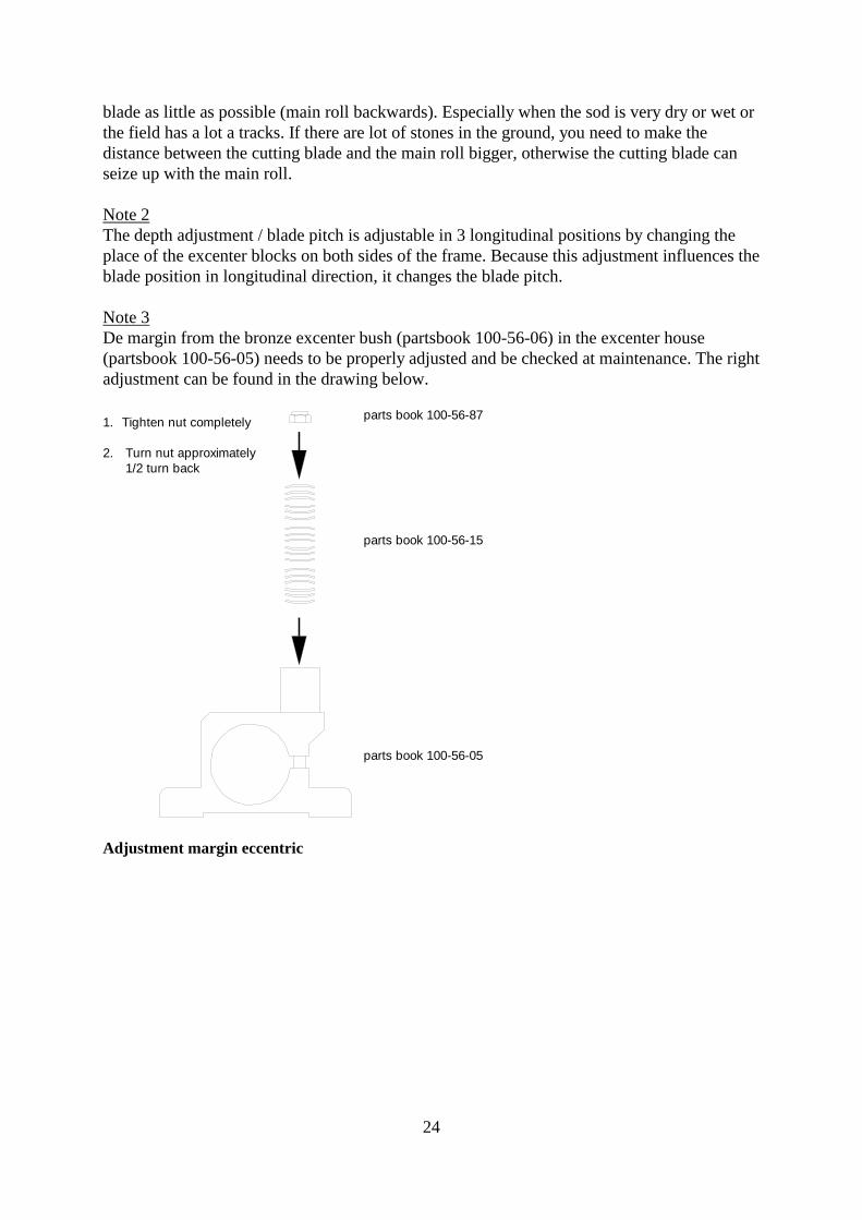
Note 3
De margin from the bronze excenter bush (partsbook 100-56-06) in the excenter house
(partsbook 100-56-05) needs to be properly adjusted and be checked at maintenance. The right
adjustment can be found in the drawing below.
1. Tighten nut completely
2. Turn nut approximately
1/2 turn back
parts book 100-56-87
parts book 100-56-15
parts book 100-56-05
Adjustment margin eccentric

25
Note 4.
For normal use the range of the depth adjustment described in the chapter “usage” is
sufficient. If you want an even bigger adjustment range, it is possible to change the position of
the side plates (parts book 100-56-59) in relation to the adjustable depth clamp (parts book
100-56-03) by choosing different mounting holes. Look at the drawing below.
parts book
parts book
parts book
parts book
combination
combinationcombinationcombination
Adjustment possibilities for change of depth.
26
Note 5.
The cutting knife engine drives through 3 v-belts the crankshaft from the cutting knife. The
tension of the v-belt can be changed, by sliding the frame; the cutting knife engine is mounted
to.
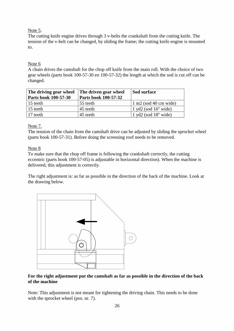
Note 6
A chain drives the camshaft for the chop off knife from the main roll. With the choice of two
gear wheels (parts book 100-57-30 en 100-57-32) the length at which the sod is cut off can be
changed.
The driving gear wheel
Parts book 100-57-30
The driven gear wheel
Parts book 100-57-32
Sod surface
15 teeth 55 teeth 1 m2 (sod 40 cm wide)
15 teeth 45 teeth 1 yd2 (sod 16'' wide)
17 teeth 45 teeth 1 yd2 (sod 18'' wide)
Note 7.
The tension of the chain from the camshaft drive can be adjusted by sliding the sprocket wheel
(parts book 100-57-31). Before doing the screening roof needs to be removed.
Note 8
To make sure that the chop off frame is following the crankshaft correctly, the cutting
eccentric (parts book 100-57-05) is adjustable in horizontal direction). When the machine is
delivered, this adjustment is correctly.
The right adjustment is: as far as possible in the direction of the back of the machine. Look at
the drawing below.
For the right adjustment put the camshaft as far as possible in the direction of the back
of the machine
Note: This adjustment is not meant for tightening the driving chain. This needs to be done
with the sprocket wheel (pos. nr. 7).
27
7.4.3. Main frame
The main conveyor belt is mounted on the main frame. The main adjustment points are:
- Adjustment conveyor belt tension
- Adjustment scrapers upper and lower belt roll
Adjustment tension main conveyor belts
The right tension of the main conveyor belts is important. In the images below the adjusting of
this tension is indicated.
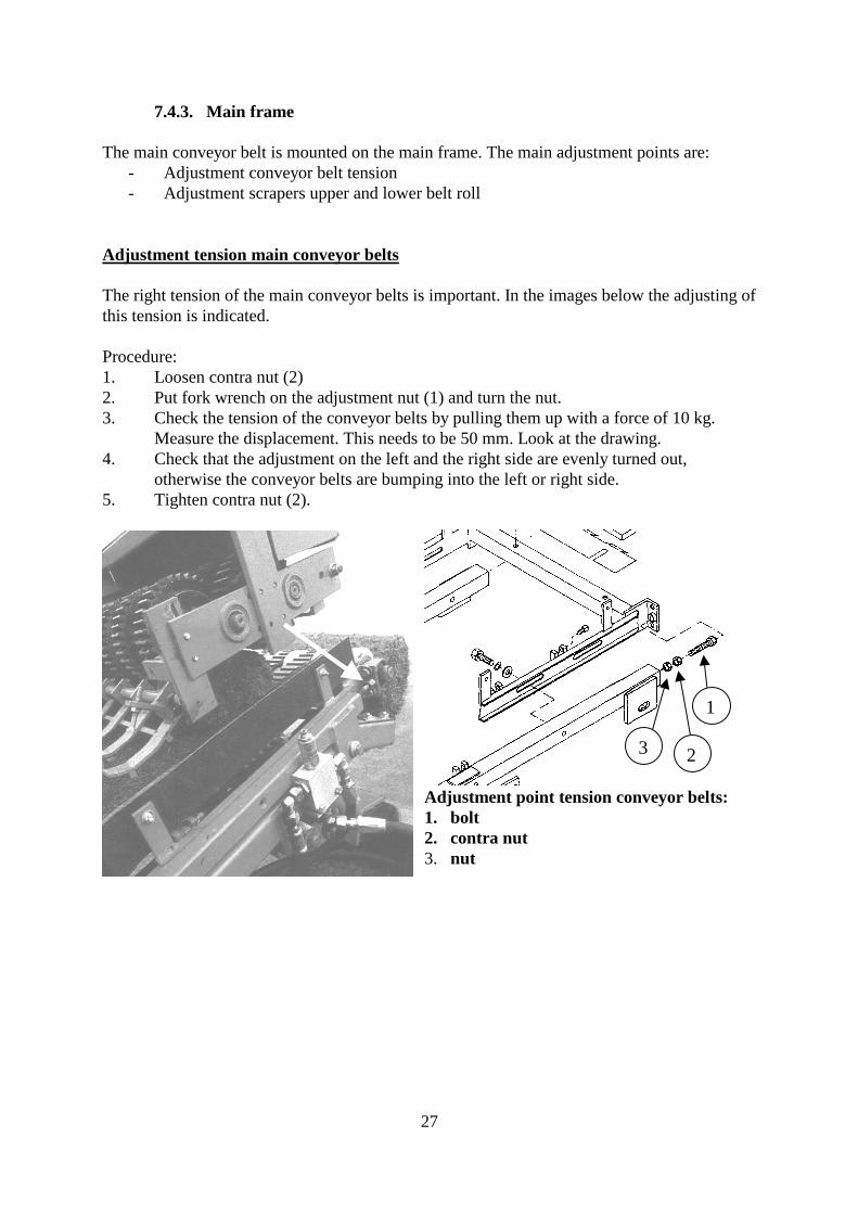
Procedure:
1. Loosen contra nut (2)
2. Put fork wrench on the adjustment nut (1) and turn the nut.
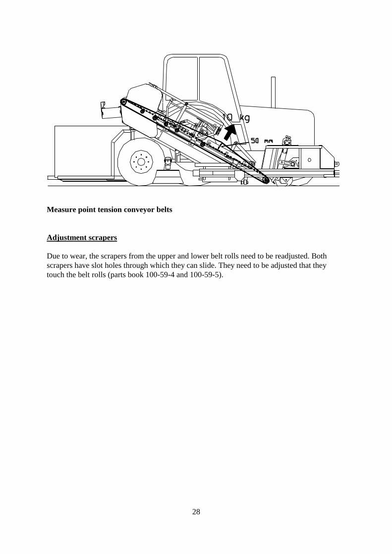
3. Check the tension of the conveyor belts by pulling them up with a force of 10 kg.
Measure the displacement. This needs to be 50 mm. Look at the drawing.
4. Check that the adjustment on the left and the right side are evenly turned out,
otherwise the conveyor belts are bumping into the left or right side.
5. Tighten contra nut (2).
1
23
Adjustment point tension conveyor belts:
1. bolt
2. contra nut
3. nut
28
Measure point tension conveyor belts
Adjustment scrapers
Due to wear, the scrapers from the upper and lower belt rolls need to be readjusted. Both
scrapers have slot holes through which they can slide. They need to be adjusted that they
touch the belt rolls (parts book 100-59-4 and 100-59-5).
29
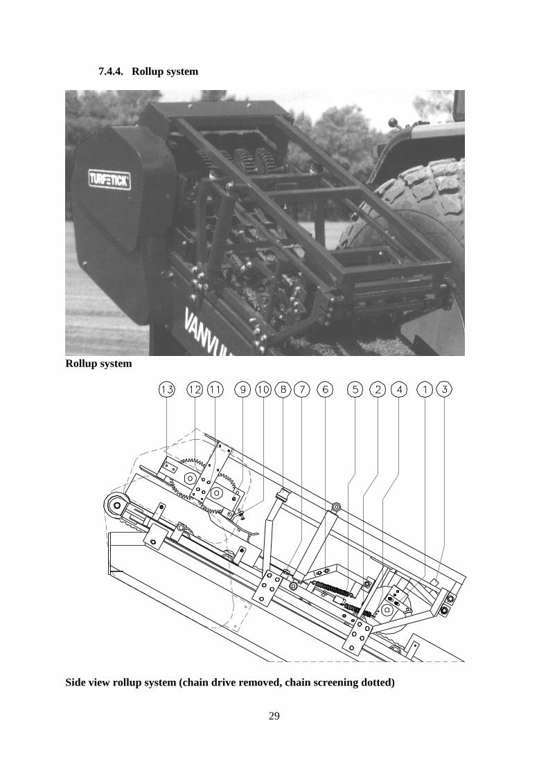
7.4.4. Rollup system
Rollup system
Side view rollup system (chain drive removed, chain screening dotted)
30
Settings and adjustment rollup system
Nr. Way to adjust Parts book
I starting part
1 Slot hole adjustment 101-50-14
2 Bolt and contra nut 101-50-62 + 60
3 Turning in/out rubber stop and contra nut 101-50-32 + 60
II rolling board part
4 Choice hole spring connection 101-50-10
5 Choice hole spring connection 101-50-23
6 Choice hole + adjustment slot hole 101-50-05 + 06
7 Turning in/out rubber stop and contra nut 101-50-32 + 60
III rolling wheels part
8 Moving synthetic material ring 101-50-27
9 Slot hole adjustment 101-51-08 + 09
10 Bolt and contra nut 101-51-32 + 56
11 Slot hole adjustment 101-51-06
13 Slot hole adjustment 101-51-07
13 Slot hole adjustment 101-51-02 + 42
After this part the different settings and adjustments are explained. Goal of a correct adjusted
rollup system is to roll the sod into tight rolls and that they come out of the rollup system in
the right position.
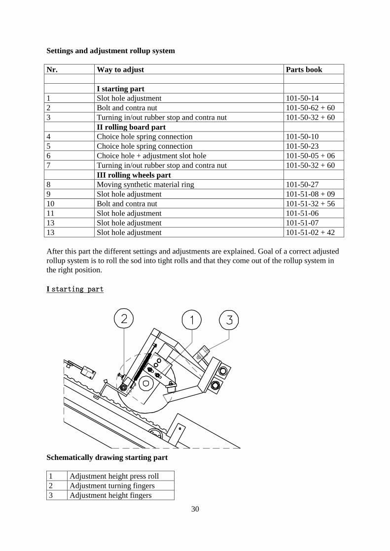
I starting part
Schematically drawing starting part
1 Adjustment height press roll
2 Adjustment turning fingers
3 Adjustment height fingers
31
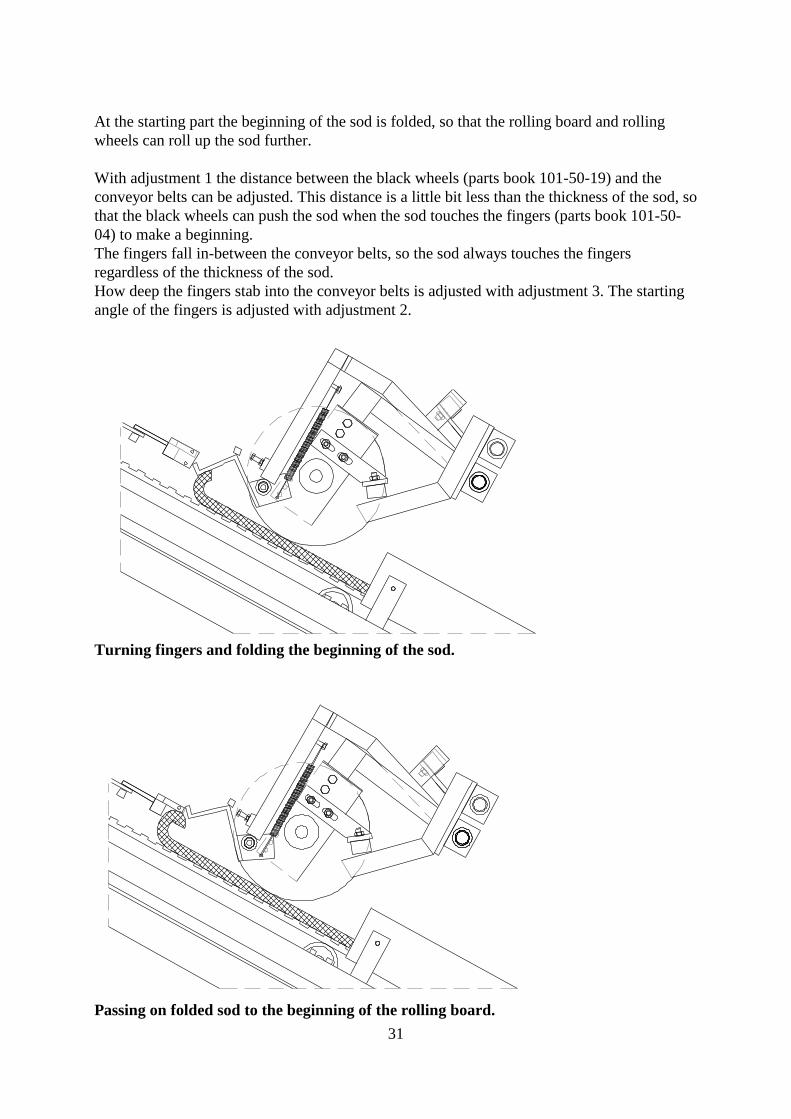
At the starting part the beginning of the sod is folded, so that the rolling board and rolling
wheels can roll up the sod further.
With adjustment 1 the distance between the black wheels (parts book 101-50-19) and the
conveyor belts can be adjusted. This distance is a little bit less than the thickness of the sod, so
that the black wheels can push the sod when the sod touches the fingers (parts book 101-50-
04) to make a beginning.
The fingers fall in-between the conveyor belts, so the sod always touches the fingers
regardless of the thickness of the sod.
How deep the fingers stab into the conveyor belts is adjusted with adjustment 3. The starting
angle of the fingers is adjusted with adjustment 2.
Turning fingers and folding the beginning of the sod.
Passing on folded sod to the beginning of the rolling board.
32
If the fingers are stabbing too deep in-between the conveyor belts, the sod will only be folded
and no beginning of the roll is made.
If the fingers are stabbing not deep enough in-between the conveyor belt, the sod will not be
folded, only lifted up a little bit, so there is not made a beginning of a roll. In case of very
loose sods, it could be necessary that 1 of the 2 springs (parts book 101-50-30) is removed.
The right adjustment of the starting part is important and can be varied dependent on the type
en thickness of the sod.
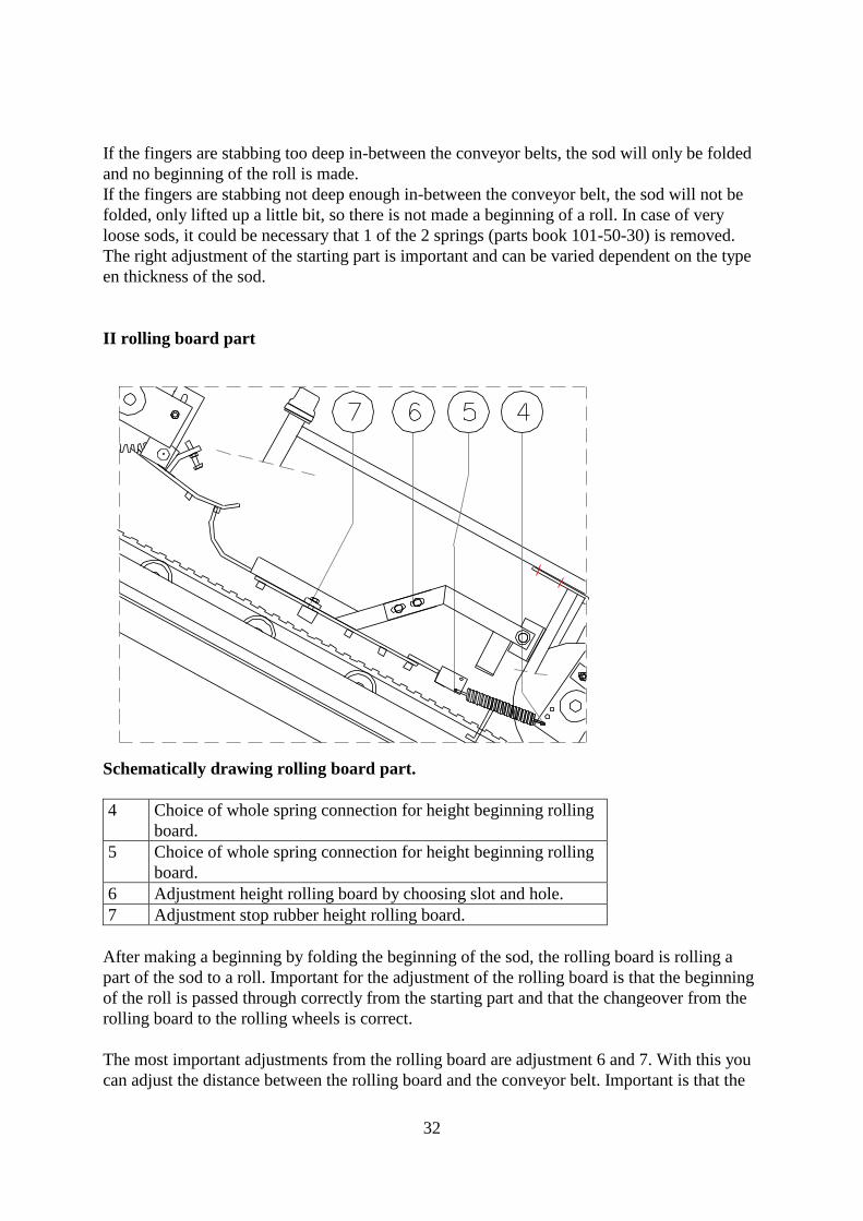
II rolling board part
Schematically drawing rolling board part.
4 Choice of whole spring connection for height beginning rolling
board.
5 Choice of whole spring connection for height beginning rolling
board.
6 Adjustment height rolling board by choosing slot and hole.
7 Adjustment stop rubber height rolling board.
After making a beginning by folding the beginning of the sod, the rolling board is rolling a
part of the sod to a roll. Important for the adjustment of the rolling board is that the beginning
of the roll is passed through correctly from the starting part and that the changeover from the
rolling board to the rolling wheels is correct.
The most important adjustments from the rolling board are adjustment 6 and 7. With this you
can adjust the distance between the rolling board and the conveyor belt. Important is that the
33
distance between the rolling board and the conveyor belt is bigger than the thickness of the
sod. However, if the distance is getting too big, the sod can’t be rolled any more.
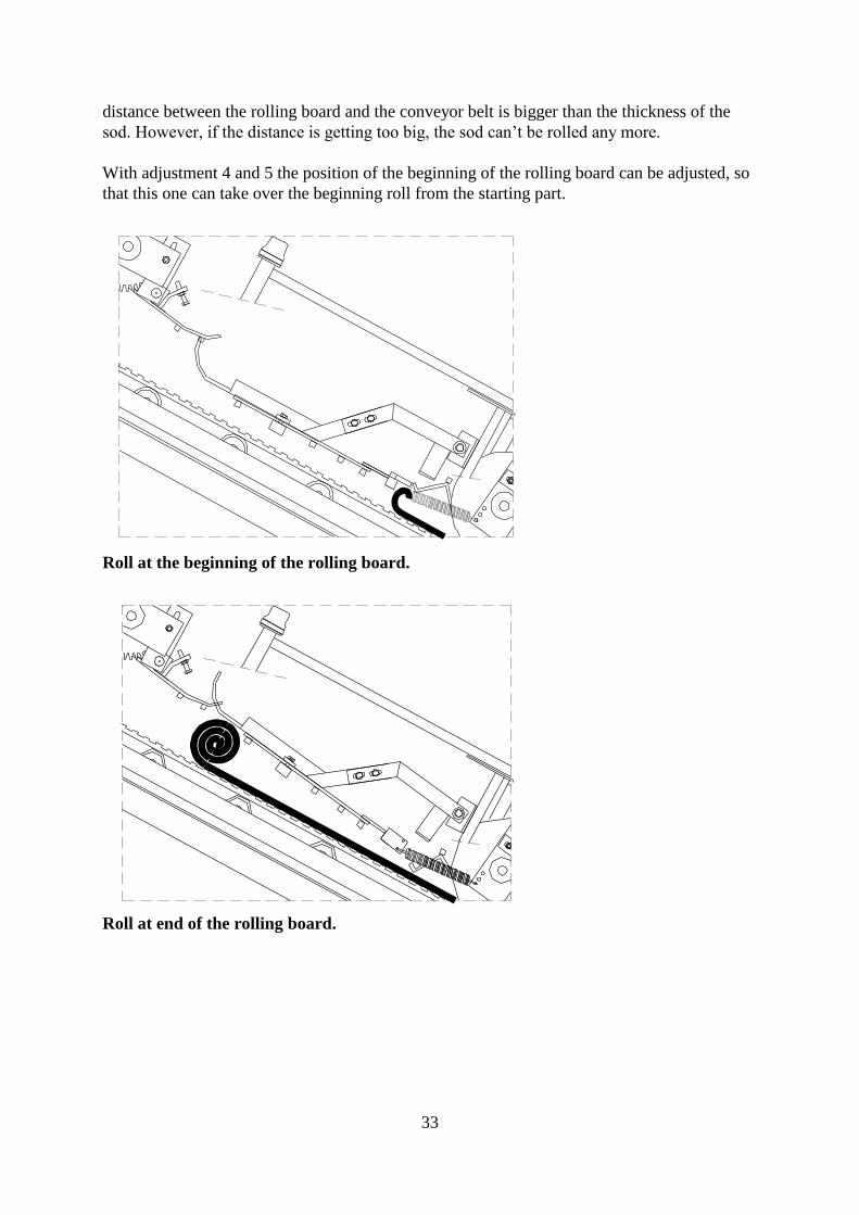
With adjustment 4 and 5 the position of the beginning of the rolling board can be adjusted, so
that this one can take over the beginning roll from the starting part.
Roll at the beginning of the rolling board.
Roll at end of the rolling board.
34
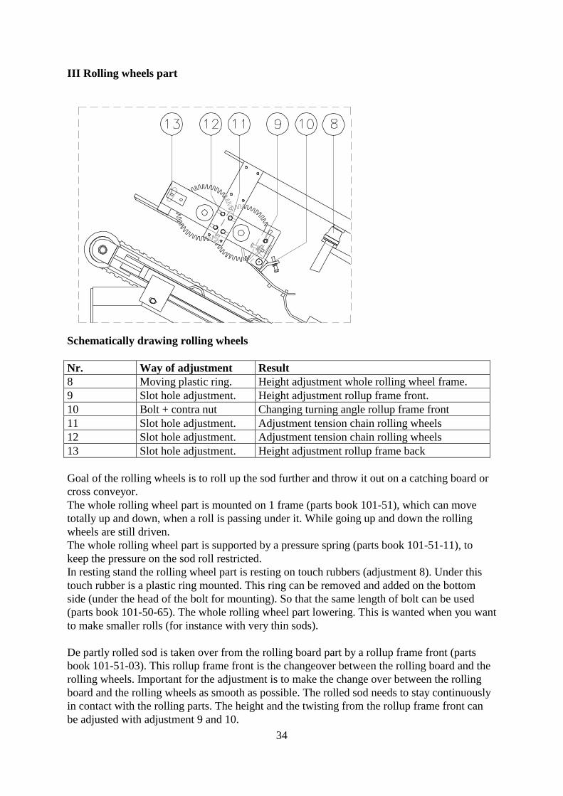
III Rolling wheels part
Schematically drawing rolling wheels
Nr. Way of adjustment Result
8 Moving plastic ring. Height adjustment whole rolling wheel frame.
9 Slot hole adjustment. Height adjustment rollup frame front.
10 Bolt + contra nut Changing turning angle rollup frame front
11 Slot hole adjustment. Adjustment tension chain rolling wheels
12 Slot hole adjustment. Adjustment tension chain rolling wheels
13 Slot hole adjustment. Height adjustment rollup frame back
Goal of the rolling wheels is to roll up the sod further and throw it out on a catching board or
cross conveyor.
The whole rolling wheel part is mounted on 1 frame (parts book 101-51), which can move
totally up and down, when a roll is passing under it. While going up and down the rolling
wheels are still driven.
The whole rolling wheel part is supported by a pressure spring (parts book 101-51-11), to
keep the pressure on the sod roll restricted.
In resting stand the rolling wheel part is resting on touch rubbers (adjustment 8). Under this
touch rubber is a plastic ring mounted. This ring can be removed and added on the bottom
side (under the head of the bolt for mounting). So that the same length of bolt can be used
(parts book 101-50-65). The whole rolling wheel part lowering. This is wanted when you want
to make smaller rolls (for instance with very thin sods).
De partly rolled sod is taken over from the rolling board part by a rollup frame front (parts
book 101-51-03). This rollup frame front is the changeover between the rolling board and the
rolling wheels. Important for the adjustment is to make the change over between the rolling
board and the rolling wheels as smooth as possible. The rolled sod needs to stay continuously
in contact with the rolling parts. The height and the twisting from the rollup frame front can
be adjusted with adjustment 9 and 10.
35
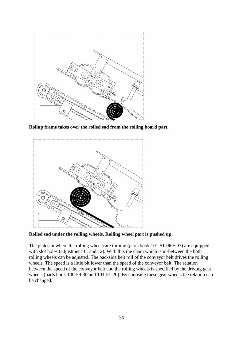
Rollup frame takes over the rolled sod from the rolling board part.
Rolled sod under the rolling wheels. Rolling wheel part is pushed up.
The plates in where the rolling wheels are turning (parts book 101-51-06 + 07) are equipped
with slot holes (adjustment 11 and 12). With this the chain which is in-between the both
rolling wheels can be adjusted. The backside belt roll of the conveyor belt drives the rolling
wheels. The speed is a little bit lower than the speed of the conveyor belt. The relation
between the speed of the conveyor belt and the rolling wheels is specified by the driving gear
wheels (parts book 100-59-30 and 101-51-20). By choosing these gear wheels the relation can
be changed.
36
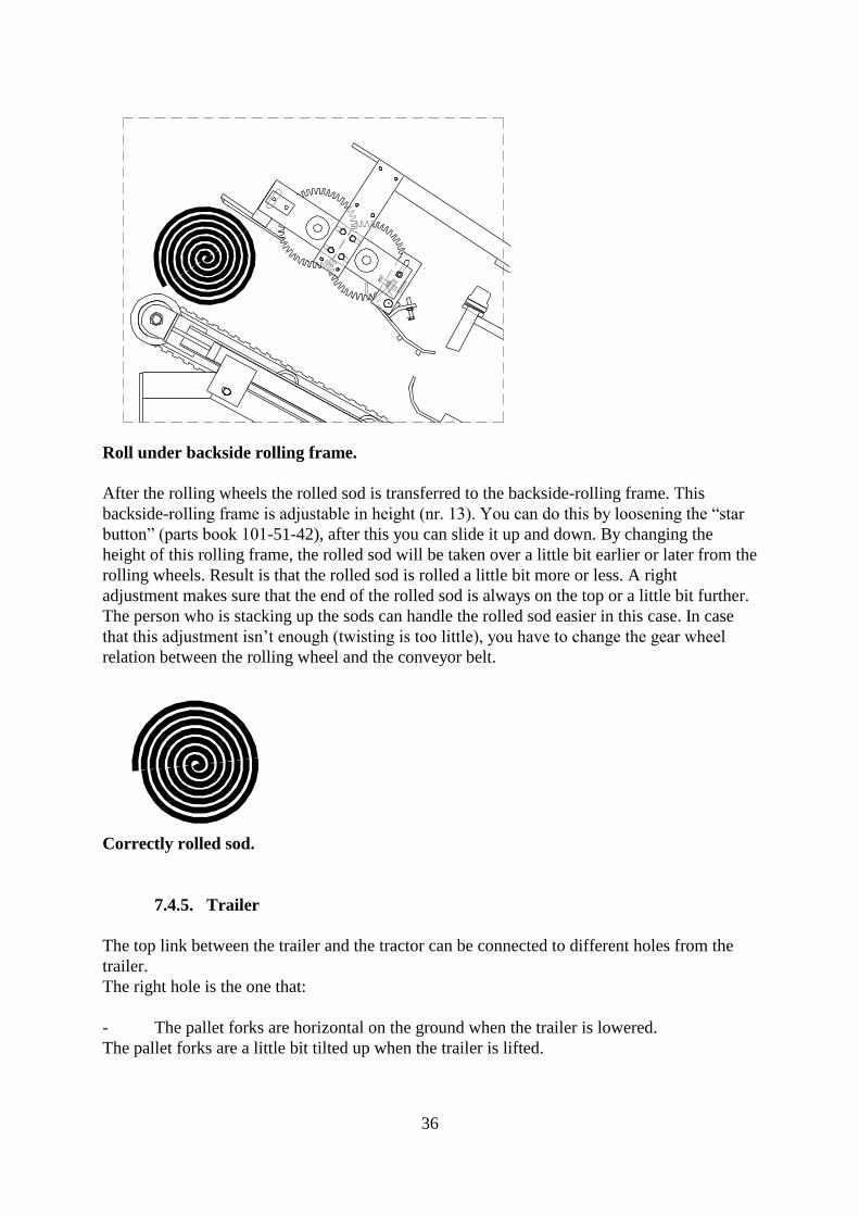
Roll under backside rolling frame.
After the rolling wheels the rolled sod is transferred to the backside-rolling frame. This
backside-rolling frame is adjustable in height (nr. 13). You can do this by loosening the “star
button” (parts book 101-51-42), after this you can slide it up and down. By changing the
height of this rolling frame, the rolled sod will be taken over a little bit earlier or later from the
rolling wheels. Result is that the rolled sod is rolled a little bit more or less. A right
adjustment makes sure that the end of the rolled sod is always on the top or a little bit further.
The person who is stacking up the sods can handle the rolled sod easier in this case. In case
that this adjustment isn’t enough (twisting is too little), you have to change the gear wheel
relation between the rolling wheel and the conveyor belt.
Correctly rolled sod.
7.4.5. Trailer
The top link between the trailer and the tractor can be connected to different holes from the
trailer.
The right hole is the one that:
- The pallet forks are horizontal on the ground when the trailer is lowered.
The pallet forks are a little bit tilted up when the trailer is lifted.
37
8. Maintenance
Proper maintenance is important for economic and profitable lifetime use of the machine and
it’s necessary for safe operation of the machine.
Follow the maintenance schedule as given below.
Check the machine on regular basis for play of the different components and also on loose or
vibrating bolts and components.
8.1. Maintenance schedule
The maintenance schedule can be split as follows:
- Maintenance 1 x each day
- Maintenance 1 x each week
- Maintenance 1 x each month
- Maintenance 1 x yearly
- Maintenance 1 x every 2 year
- Maintenance after 20 hectares (app. 50 acres) turf are cut
A number of unmentioned points are further described below.
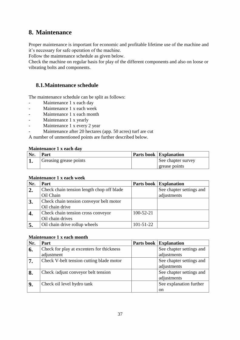
Maintenance 1 x each day
Nr. Part Parts book Explanation
1. Greasing grease points See chapter survey
grease points
Maintenance 1 x each week
Nr. Part Parts book Explanation
2. Check chain tension length chop off blade
Oil Chain
See chapter settings and
adjustments
3. Check chain tension conveyor belt motor
Oil chain drive
4. Check chain tension cross conveyor
Oil chain drives
100-52-21
5. Oil chain drive rollup wheels 101-51-22
Maintenance 1 x each month
Nr. Part Parts book Explanation
6. Check for play at excenters for thickness
adjustment
See chapter settings and
adjustments
7. Check V-belt tension cutting blade motor See chapter settings and
adjustments
8. Check /adjust conveyor belt tension See chapter settings and
adjustments
9. Check oil level hydro tank See explanation further
on
38
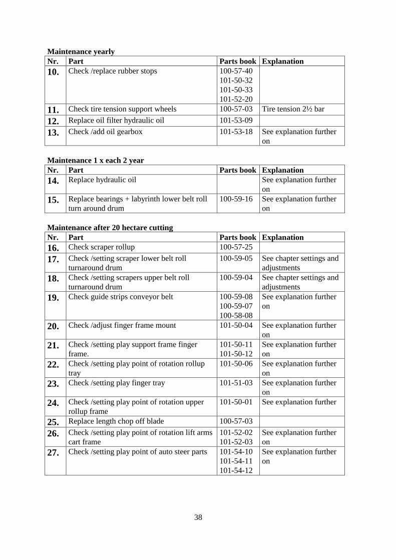
Maintenance yearly
Nr. Part Parts book Explanation
10. Check /replace rubber stops 100-57-40
101-50-32
101-50-33
101-52-20
11. Check tire tension support wheels 100-57-03 Tire tension 2½ bar
12. Replace oil filter hydraulic oil 101-53-09
13. Check /add oil gearbox 101-53-18 See explanation further
on
Maintenance 1 x each 2 year
Nr. Part Parts book Explanation
14. Replace hydraulic oil See explanation further
on
15. Replace bearings + labyrinth lower belt roll
turn around drum
100-59-16 See explanation further
on
Maintenance after 20 hectare cutting
Nr. Part Parts book Explanation
16. Check scraper rollup 100-57-25
17. Check /setting scraper lower belt roll
turnaround drum
100-59-05 See chapter settings and
adjustments
18. Check /setting scrapers upper belt roll
turnaround drum
100-59-04 See chapter settings and
adjustments
19. Check guide strips conveyor belt 100-59-08
100-59-07
100-58-08
See explanation further
on
20. Check /adjust finger frame mount 101-50-04 See explanation further
on
21. Check /setting play support frame finger
frame.
101-50-11
101-50-12
See explanation further
on
22. Check /setting play point of rotation rollup
tray
101-50-06 See explanation further
on
23. Check /setting play finger tray 101-51-03 See explanation further
on
24. Check /setting play point of rotation upper
rollup frame
101-50-01 See explanation further
25. Replace length chop off blade 100-57-03
26. Check /setting play point of rotation lift arms
cart frame
101-52-02
101-52-03
See explanation further
on
27. Check /setting play point of auto steer parts 101-54-10
101-54-11
101-54-12
See explanation further
on
39
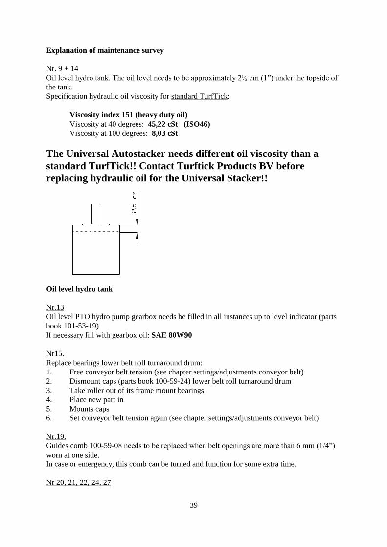
Explanation of maintenance survey
Nr. 9 + 14
Oil level hydro tank. The oil level needs to be approximately 2½ cm (1”) under the topside of
the tank.
Specification hydraulic oil viscosity for standard TurfTick:
Viscosity index 151 (heavy duty oil)
Viscosity at 40 degrees: 45,22 cSt (ISO46)
Viscosity at 100 degrees: 8,03 cSt
The Universal Autostacker needs different oil viscosity than a
standard TurfTick!! Contact Turftick Products BV before
replacing hydraulic oil for the Universal Stacker!!
Oil level hydro tank
Nr.13
Oil level PTO hydro pump gearbox needs be filled in all instances up to level indicator (parts
book 101-53-19)
If necessary fill with gearbox oil: SAE 80W90
Nr15.
Replace bearings lower belt roll turnaround drum:
1. Free conveyor belt tension (see chapter settings/adjustments conveyor belt)
2. Dismount caps (parts book 100-59-24) lower belt roll turnaround drum
3. Take roller out of its frame mount bearings
4. Place new part in
5. Mounts caps
6. Set conveyor belt tension again (see chapter settings/adjustments conveyor belt)
Nr.19.
Guides comb 100-59-08 needs to be replaced when belt openings are more than 6 mm (1/4”)
worn at one side.
In case or emergency, this comb can be turned and function for some extra time.
Nr 20, 21, 22, 24, 27

40
When mentioned rotational points have too much axial play (= in the direction of axle), this
play needs be filled out with shims.

41
Nr. 23
The axial play (in the direction of axle) can easily be adjusted through adjustment of the 2 set
bushings on the axle of the finger tray.
Nr. 26
The axial play (in the direction of the axle) can be adjusted through rotation of the nut (parts
book 101-52-60) + counter nut on this axle.

42
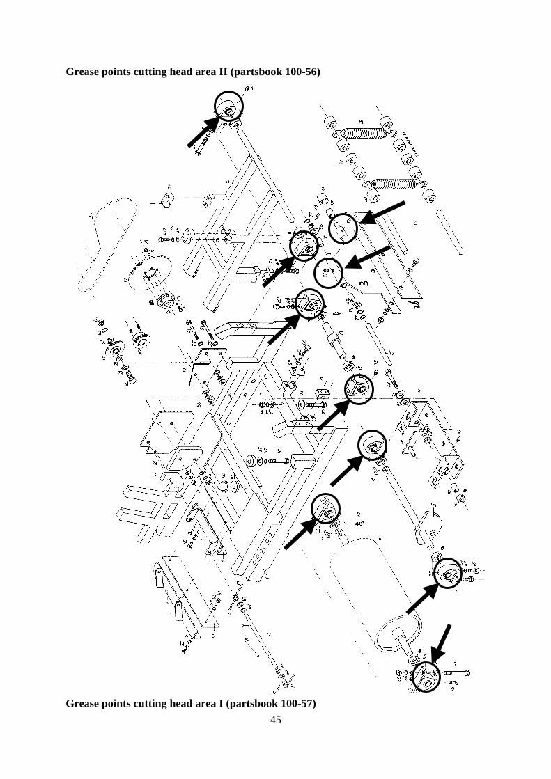
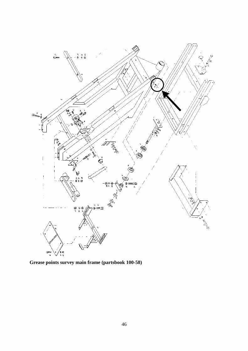
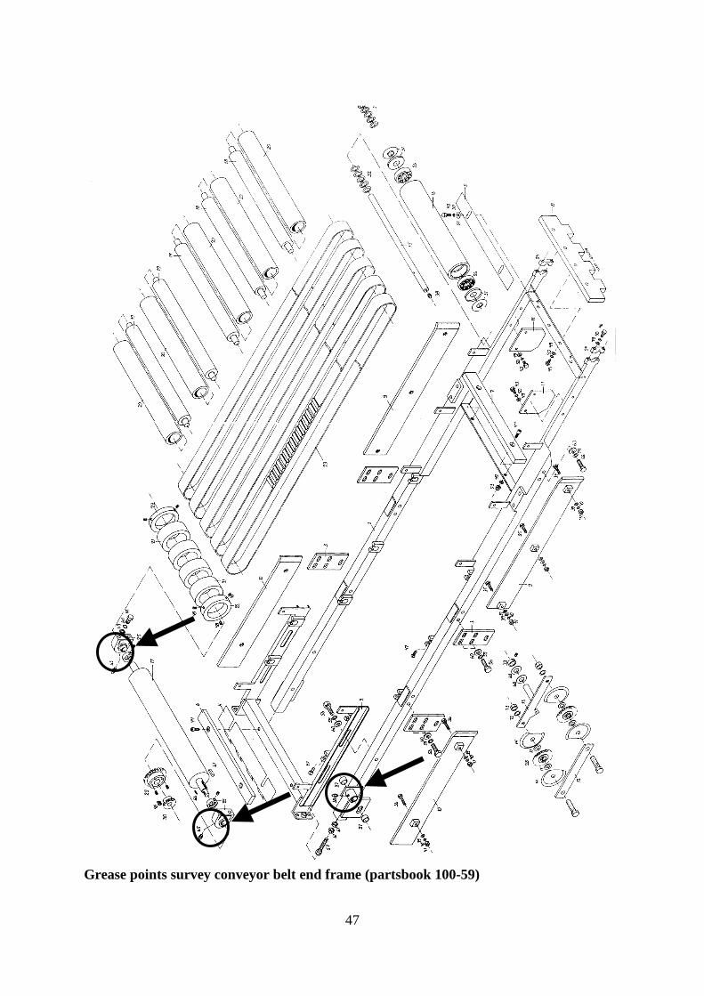
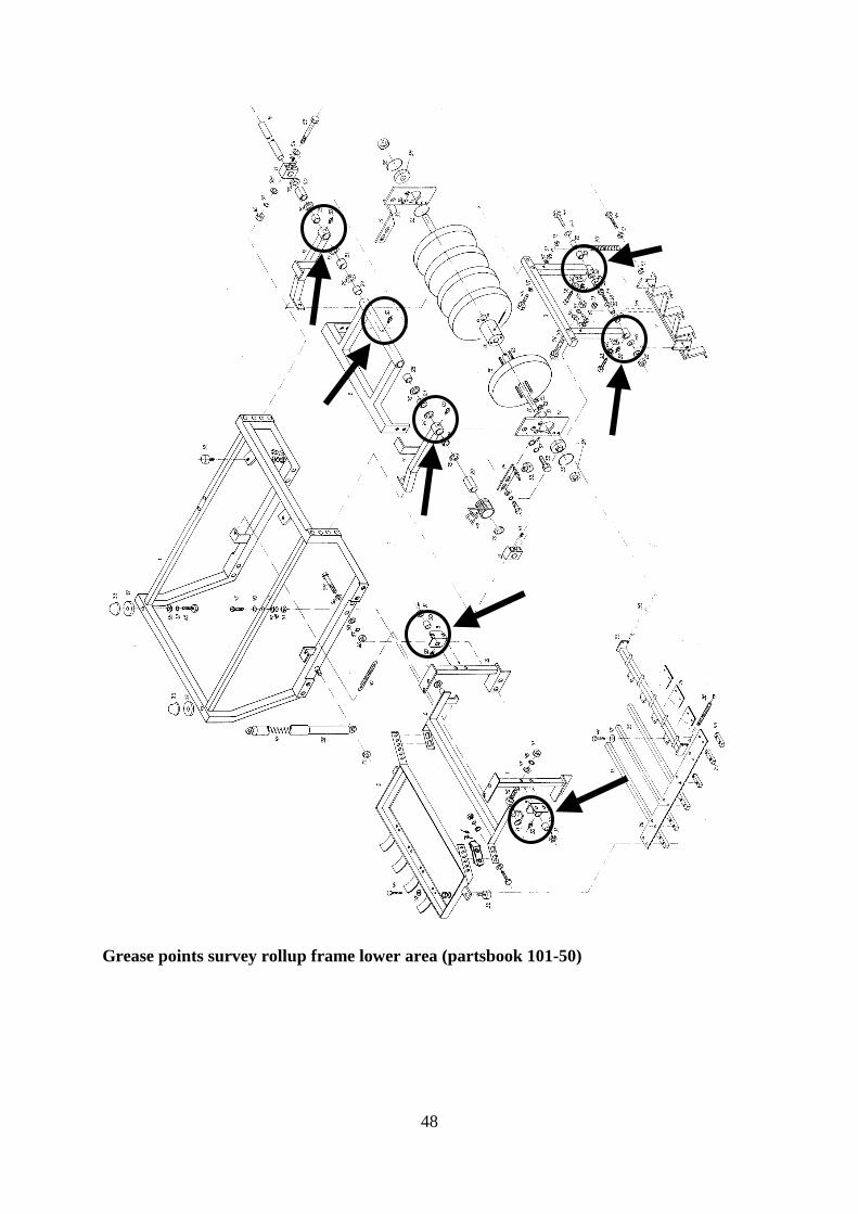
8.2. Grease points survey
In following survey is explained where the different grease nipples on the machine are
located, such that at greasing they can easily be found.
Analogues to the order followed in the parts book the pages are shown.
Name Parts book
Connecting frame 100-50
Press roll 100-51
Cutting head area II 100-56
Cutting head area I 100-57
Main frame 100-58
Conveyor belt and frame 100-59
Rollup frame, lower area 101-50
Rollup frame, upper area 101-51
Trailer 101-52
Auto steer 101-54
Grease points connecting frame (partsbook 100-50)
43
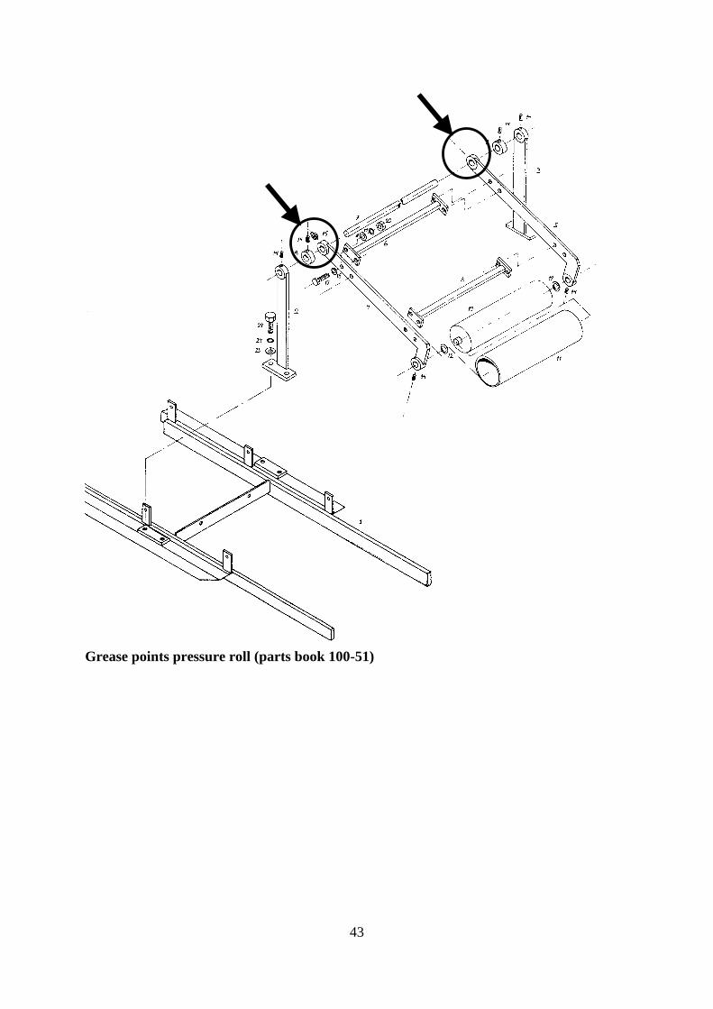
Grease points pressure roll (parts book 100-51)
44
45
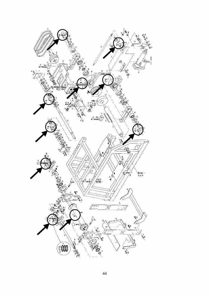
Grease points cutting head area II (partsbook 100-56)
Grease points cutting head area I (partsbook 100-57)
46
Grease points survey main frame (partsbook 100-58)
47
Grease points survey conveyor belt end frame (partsbook 100-59)
48
Grease points survey rollup frame lower area (partsbook 101-50)
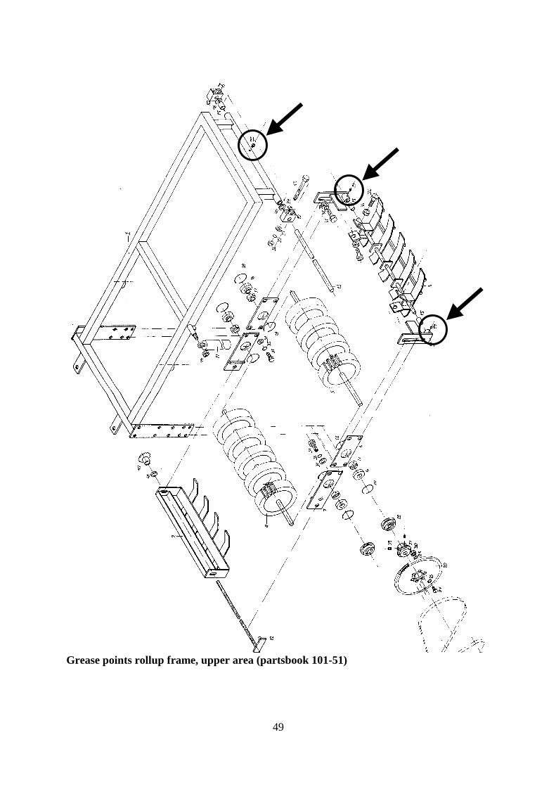
49
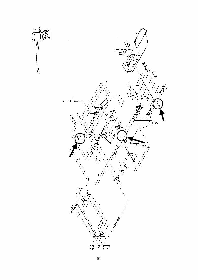
Grease points rollup frame, upper area (partsbook 101-51)
50
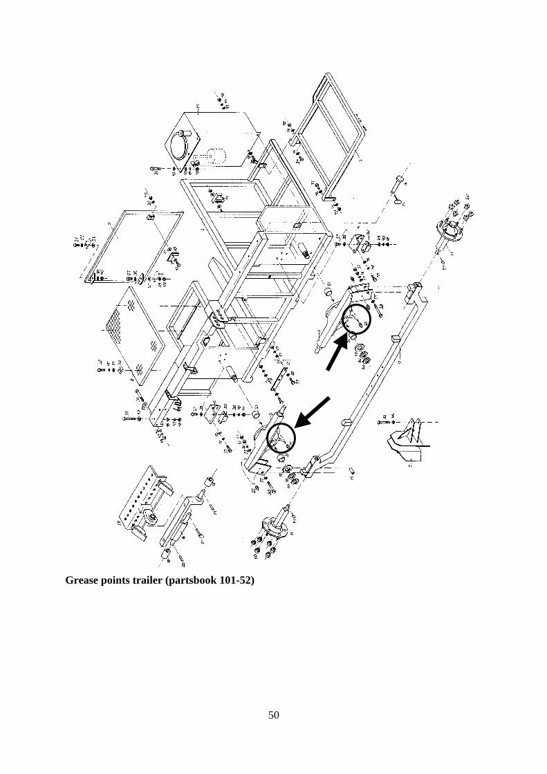
Grease points trailer (partsbook 101-52)
51
52
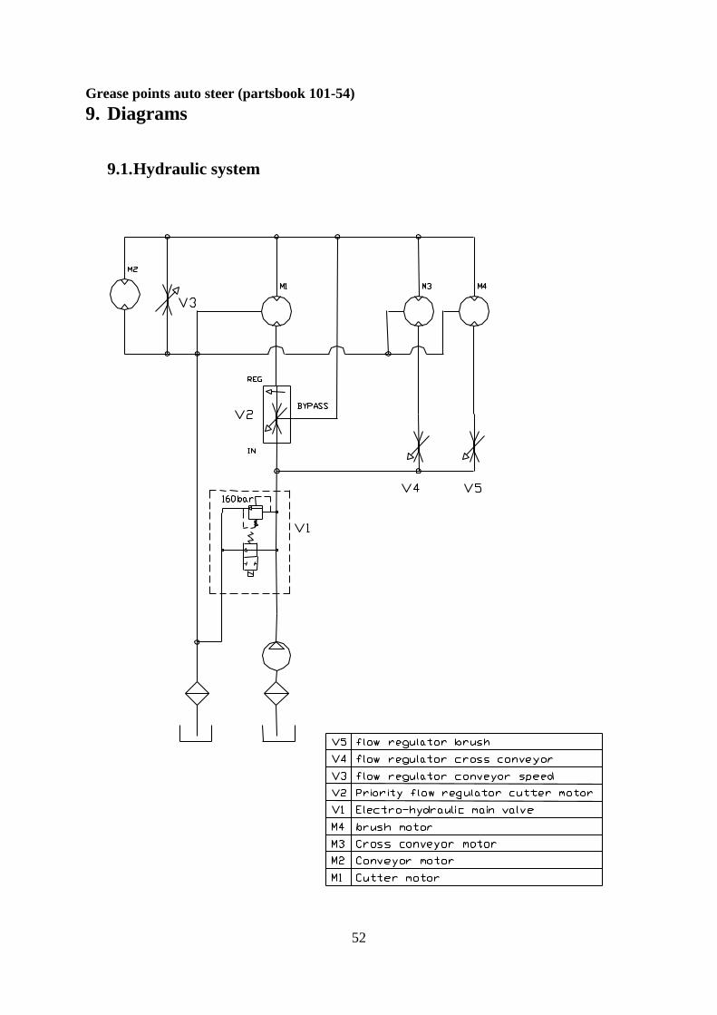
Grease points auto steer (partsbook 101-54)
9. Diagrams
9.1. Hydraulic system

53
9.2. Electrical drawings
A description and explanation of the auto steer system can be found in the separate user
manual for the auto steer system.