turbocharging and supercharging
DESCRIPTION
25. TURBOCHARGING AND SUPERCHARGING. Figure 25-1 A supercharger on a Ford V-8. Figure 25-2 A turbocharger on a Toyota engine. Figure 25-3 The more air and fuel that can be packed in a cylinder, the greater the density of the air-fuel charge. - PowerPoint PPT PresentationTRANSCRIPT
© 2011 Pearson Education, Inc.All Rights Reserved
Automotive Technology, Fifth EditionJames Halderman
TURBOCHARGING AND SUPERCHARGING
25
25 TURBOCHARGING AND SUPERCHARGING
Automotive Technology, Fifth EditionJames Halderman
© 2011 Pearson Education, Inc.All Rights Reserved
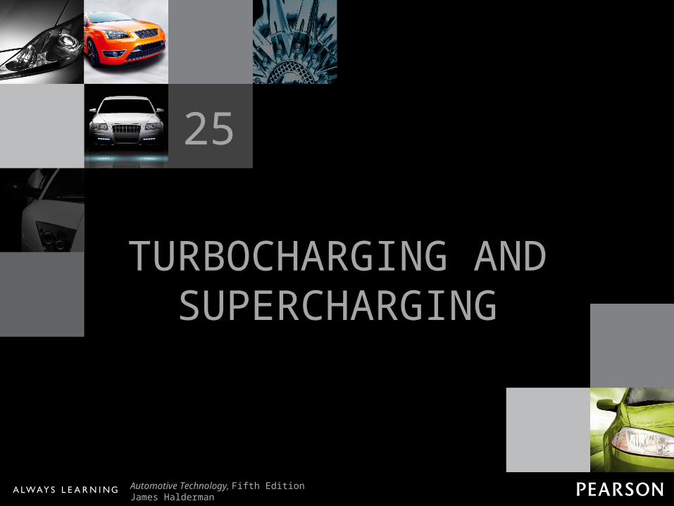
Figure 25-1 A supercharger on a Ford V-8.
25 TURBOCHARGING AND SUPERCHARGING
Automotive Technology, Fifth EditionJames Halderman
© 2011 Pearson Education, Inc.All Rights Reserved
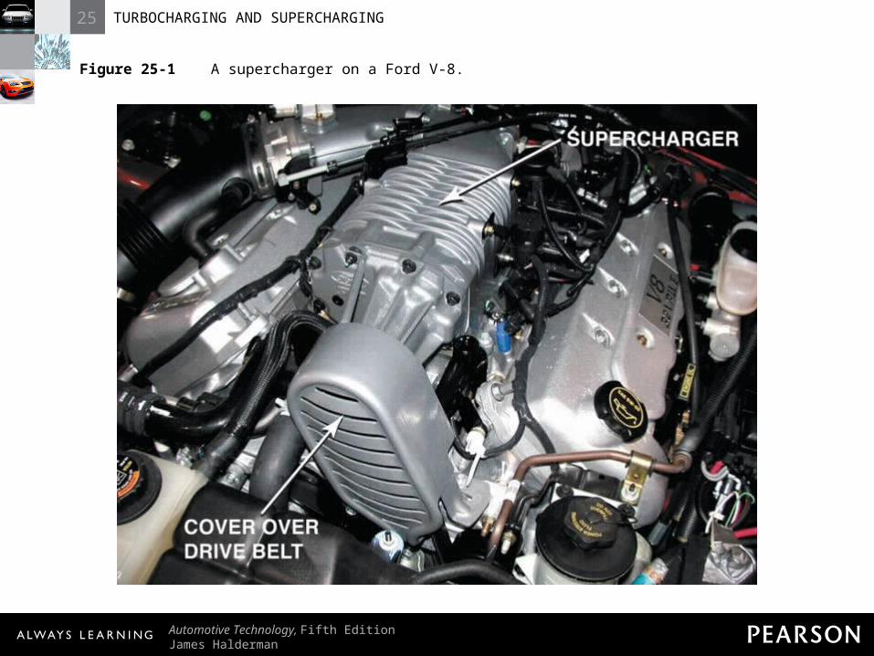
Figure 25-2 A turbocharger on a Toyota engine.
25 TURBOCHARGING AND SUPERCHARGING
Automotive Technology, Fifth EditionJames Halderman
© 2011 Pearson Education, Inc.All Rights Reserved
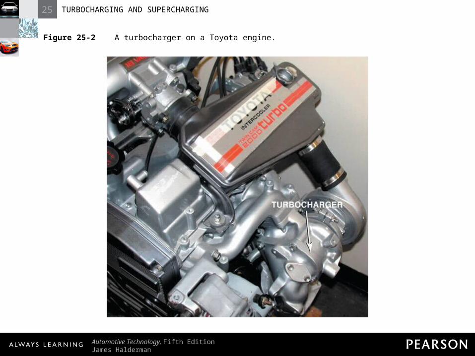
Figure 25-3 The more air and fuel that can be packed in a cylinder, the greater the density of the air-fuel charge.
25 TURBOCHARGING AND SUPERCHARGING
Automotive Technology, Fifth EditionJames Halderman
© 2011 Pearson Education, Inc.All Rights Reserved
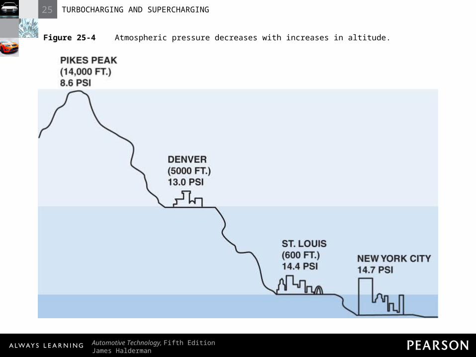
Figure 25-4 Atmospheric pressure decreases with increases in altitude.
25 TURBOCHARGING AND SUPERCHARGING
Automotive Technology, Fifth EditionJames Halderman
© 2011 Pearson Education, Inc.All Rights Reserved
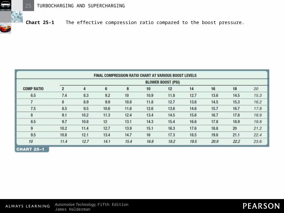
Chart 25-1 The effective compression ratio compared to the boost pressure.
25 TURBOCHARGING AND SUPERCHARGING
Automotive Technology, Fifth EditionJames Halderman
© 2011 Pearson Education, Inc.All Rights Reserved
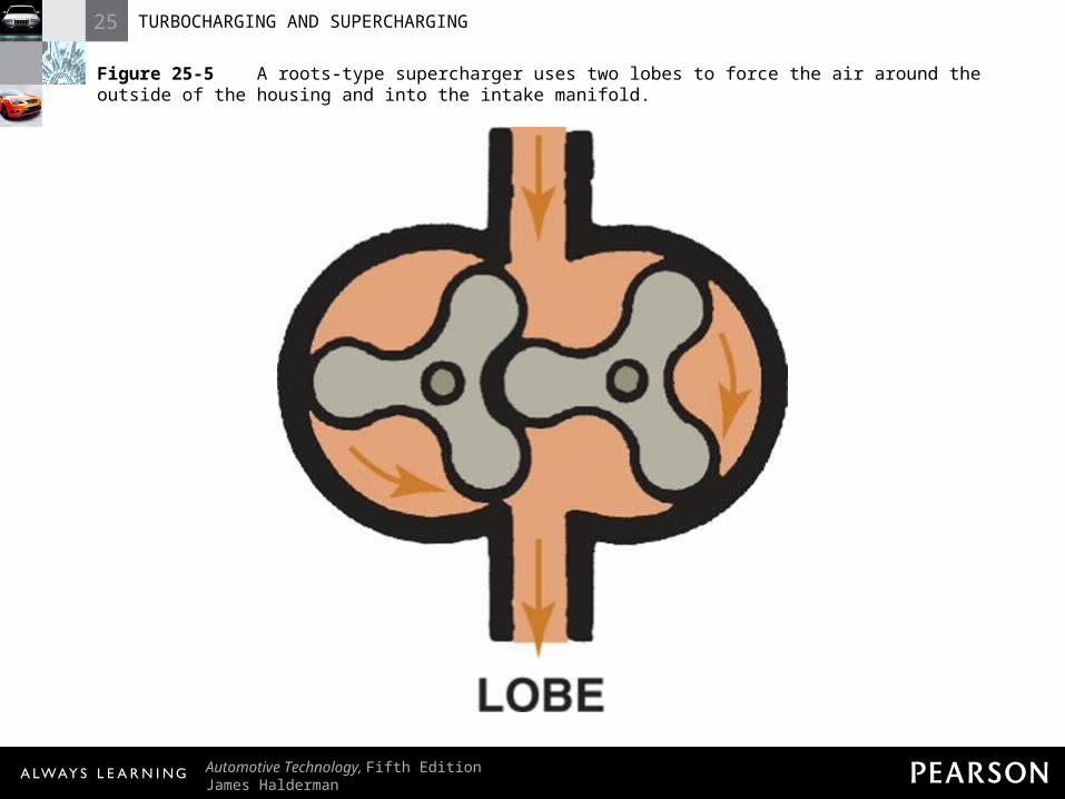
Figure 25-5 A roots-type supercharger uses two lobes to force the air around the outside of the housing and into the intake manifold.
25 TURBOCHARGING AND SUPERCHARGING
Automotive Technology, Fifth EditionJames Halderman
© 2011 Pearson Education, Inc.All Rights Reserved
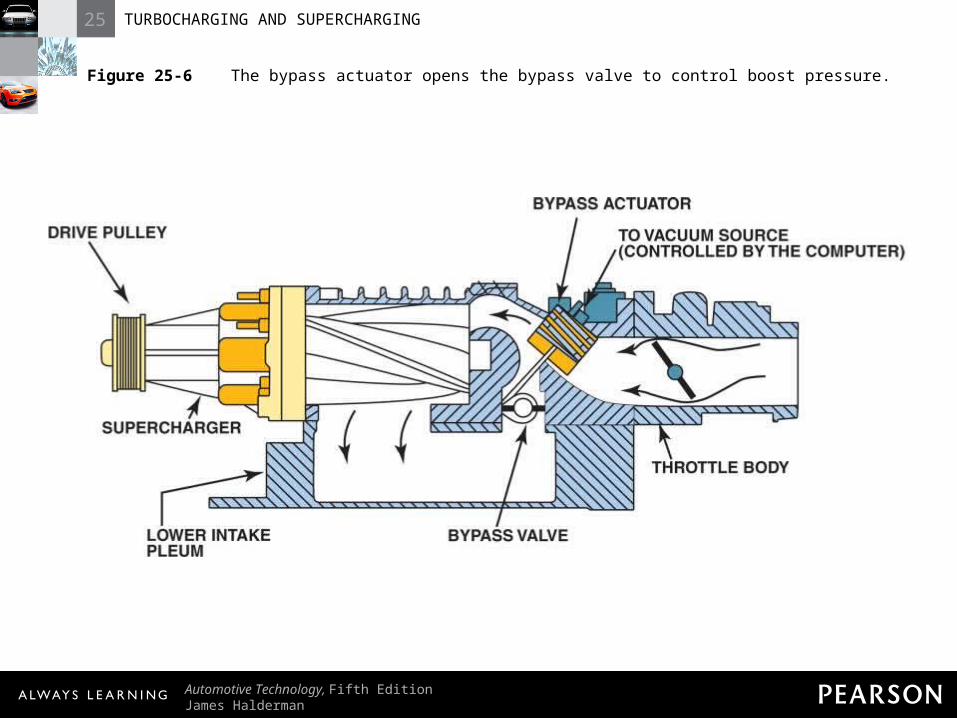
Figure 25-6 The bypass actuator opens the bypass valve to control boost pressure.
25 TURBOCHARGING AND SUPERCHARGING
Automotive Technology, Fifth EditionJames Halderman
© 2011 Pearson Education, Inc.All Rights Reserved
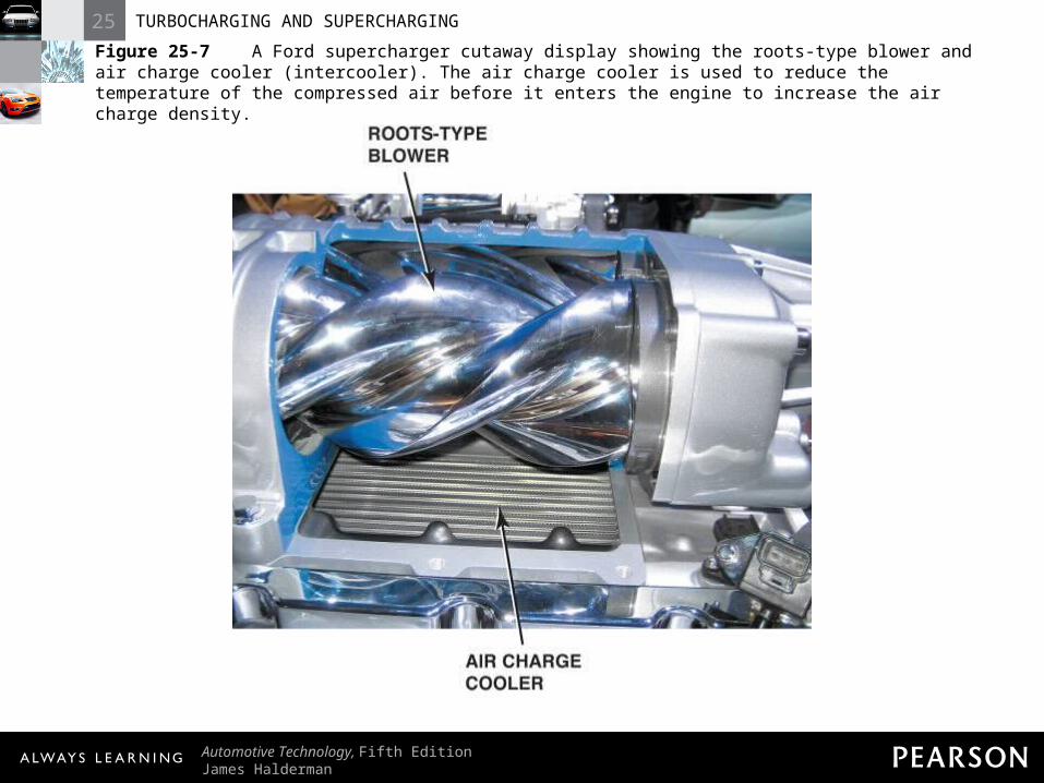
Figure 25-7 A Ford supercharger cutaway display showing the roots-type blower and air charge cooler (intercooler). The air charge cooler is used to reduce the temperature of the compressed air before it enters the engine to increase the air charge density.
25 TURBOCHARGING AND SUPERCHARGING
Automotive Technology, Fifth EditionJames Halderman
© 2011 Pearson Education, Inc.All Rights Reserved
TECH TIP: Faster Moves More Air One of the high-performance measures that can be used to increase horsepower on a supercharged engine is to install a smaller diameter pulley. The smaller the pulley diameter, the faster the supercharger will rotate and the higher the potential boost pressure will be. The change will require a shorter belt, and the extra boost could cause serious engine damage.
25 TURBOCHARGING AND SUPERCHARGING
Automotive Technology, Fifth EditionJames Halderman
© 2011 Pearson Education, Inc.All Rights Reserved
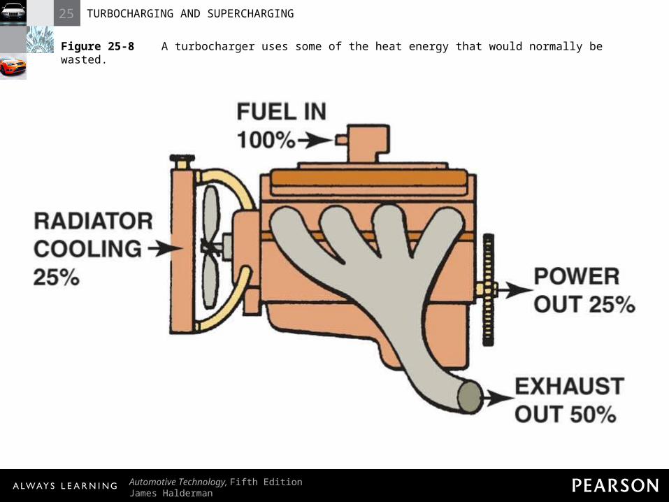
Figure 25-8 A turbocharger uses some of the heat energy that would normally be wasted.
25 TURBOCHARGING AND SUPERCHARGING
Automotive Technology, Fifth EditionJames Halderman
© 2011 Pearson Education, Inc.All Rights Reserved
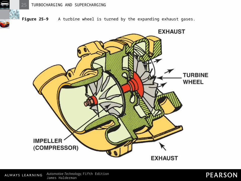
Figure 25-9 A turbine wheel is turned by the expanding exhaust gases.
25 TURBOCHARGING AND SUPERCHARGING
Automotive Technology, Fifth EditionJames Halderman
© 2011 Pearson Education, Inc.All Rights Reserved
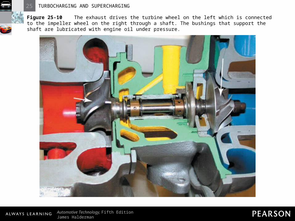
Figure 25-10 The exhaust drives the turbine wheel on the left which is connected to the impeller wheel on the right through a shaft. The bushings that support the shaft are lubricated with engine oil under pressure.
25 TURBOCHARGING AND SUPERCHARGING
Automotive Technology, Fifth EditionJames Halderman
© 2011 Pearson Education, Inc.All Rights Reserved
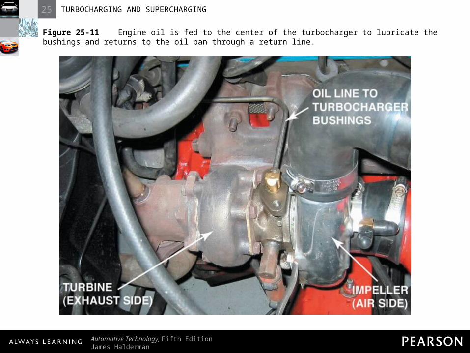
Figure 25-11 Engine oil is fed to the center of the turbocharger to lubricate the bushings and returns to the oil pan through a return line.
25 TURBOCHARGING AND SUPERCHARGING
Automotive Technology, Fifth EditionJames Halderman
© 2011 Pearson Education, Inc.All Rights Reserved
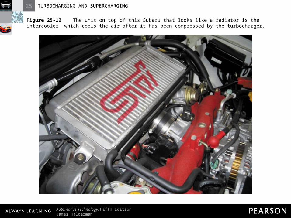
Figure 25-12 The unit on top of this Subaru that looks like a radiator is the intercooler, which cools the air after it has been compressed by the turbocharger.
25 TURBOCHARGING AND SUPERCHARGING
Automotive Technology, Fifth EditionJames Halderman
© 2011 Pearson Education, Inc.All Rights Reserved
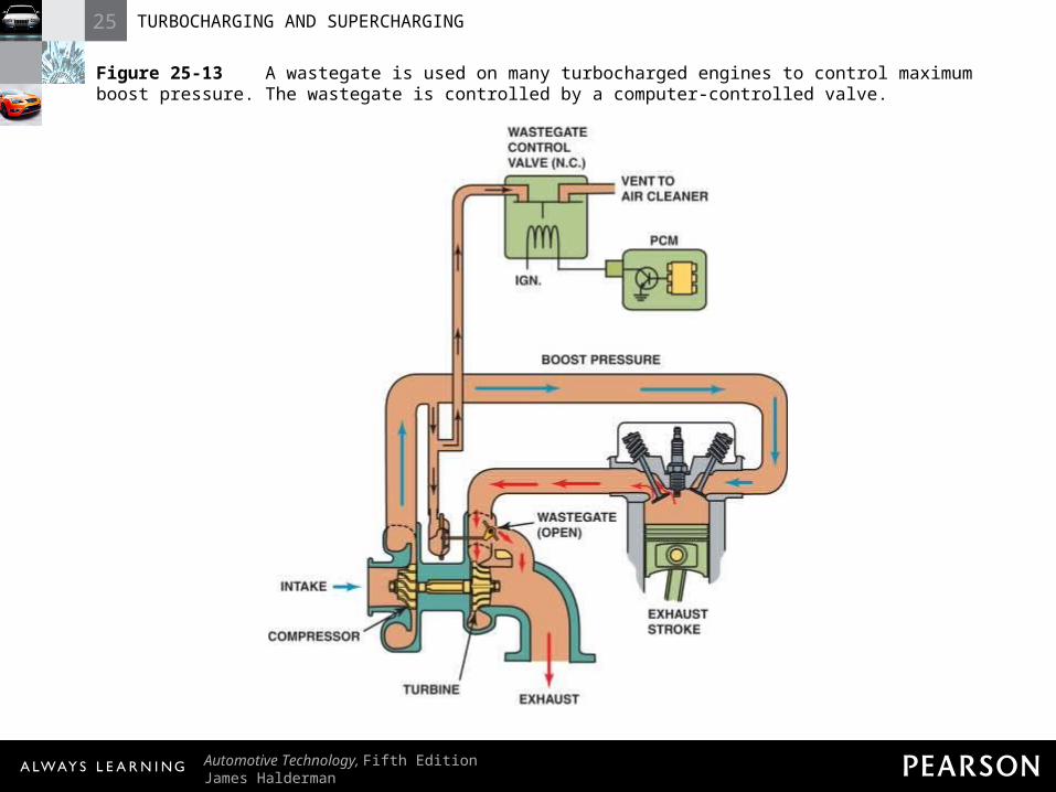
Figure 25-13 A wastegate is used on many turbocharged engines to control maximum boost pressure. The wastegate is controlled by a computer-controlled valve.
25 TURBOCHARGING AND SUPERCHARGING
Automotive Technology, Fifth EditionJames Halderman
© 2011 Pearson Education, Inc.All Rights Reserved
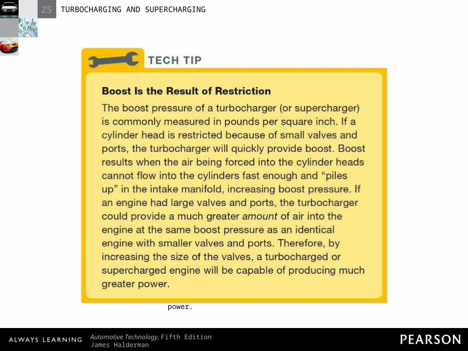
TECH TIP: Boost Is the Result of Restriction The boost pressure of a turbocharger (or supercharger) is commonly measured in pounds per square inch. If a cylinder head is restricted because of small valves and ports, the turbocharger will quickly provide boost. Boost results when the air being forced into the cylinder heads cannot flow into the cylinders fast enough and “piles up” in the intake manifold, increasing boost pressure. If an engine had large valves and ports, the turbocharger could provide a much greater amount of air into the engine at the same boost pressure as an identical engine with smaller valves and ports. Therefore, by increasing the size of the valves, a turbocharged or supercharged engine will be capable of producing much greater power.
25 TURBOCHARGING AND SUPERCHARGING
Automotive Technology, Fifth EditionJames Halderman
© 2011 Pearson Education, Inc.All Rights Reserved
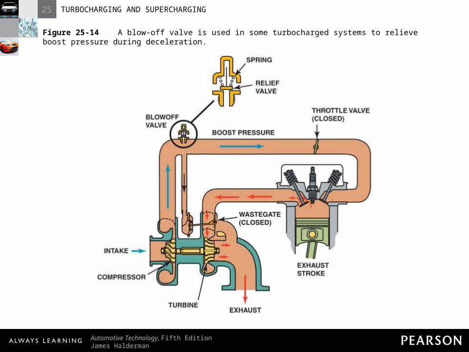
Figure 25-14 A blow-off valve is used in some turbocharged systems to relieve boost pressure during deceleration.
25 TURBOCHARGING AND SUPERCHARGING
Automotive Technology, Fifth EditionJames Halderman
© 2011 Pearson Education, Inc.All Rights Reserved
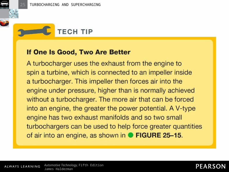
TECH TIP: If One Is Good, Two Are Better A turbocharger uses the exhaust from the engine to spin a turbine, which is connected to an impeller inside a turbocharger. This impeller then forces air into the engine under pressure, higher than is normally achieved without a turbocharger. The more air that can be forced into an engine, the greater the power potential. A V-type engine has two exhaust manifolds and so two small turbochargers can be used to help force greater quantities of air into an engine, as shown in - FIGURE 25–15 .
25 TURBOCHARGING AND SUPERCHARGING
Automotive Technology, Fifth EditionJames Halderman
© 2011 Pearson Education, Inc.All Rights Reserved
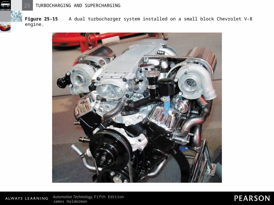
Figure 25-15 A dual turbocharger system installed on a small block Chevrolet V-8 engine.
25 TURBOCHARGING AND SUPERCHARGING
Automotive Technology, Fifth EditionJames Halderman
© 2011 Pearson Education, Inc.All Rights Reserved
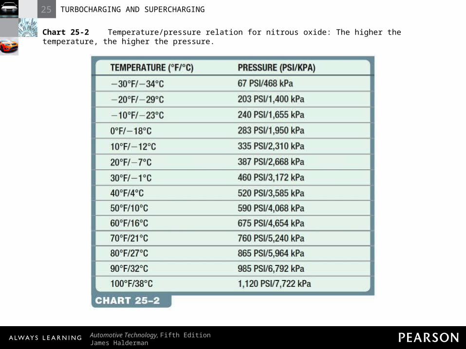
Chart 25-2 Temperature/pressure relation for nitrous oxide: The higher the temperature, the higher the pressure.
25 TURBOCHARGING AND SUPERCHARGING
Automotive Technology, Fifth EditionJames Halderman
© 2011 Pearson Education, Inc.All Rights Reserved
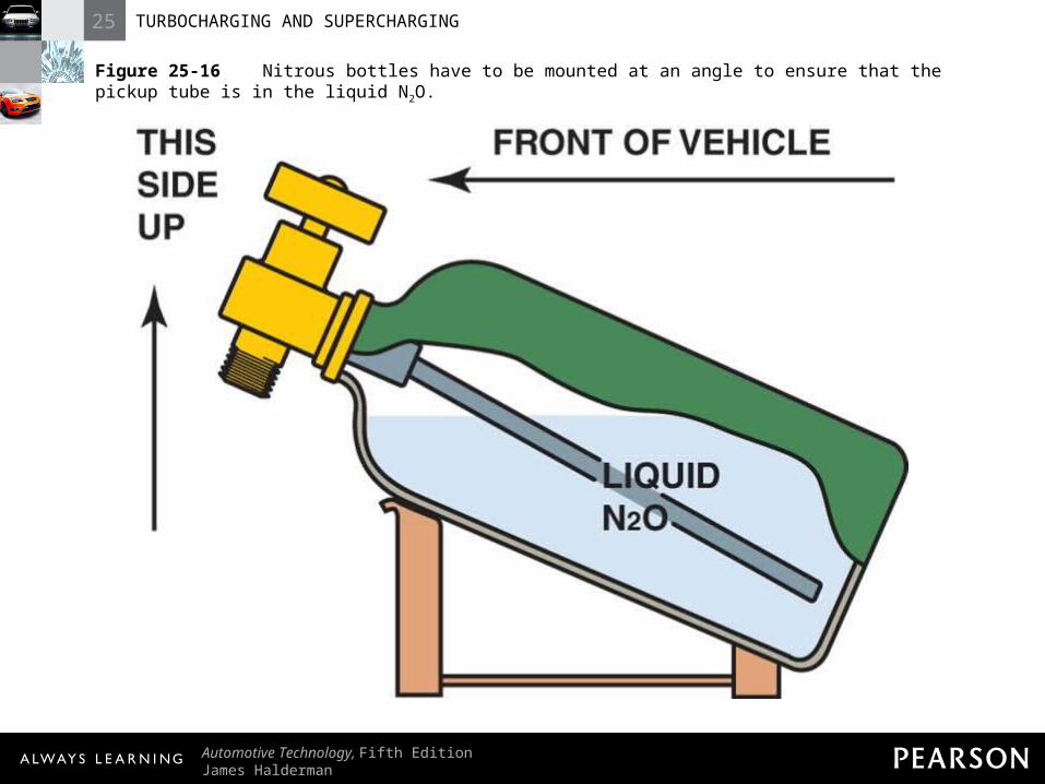
Figure 25-16 Nitrous bottles have to be mounted at an angle to ensure that the pickup tube is in the liquid N2O.
25 TURBOCHARGING AND SUPERCHARGING
Automotive Technology, Fifth EditionJames Halderman
© 2011 Pearson Education, Inc.All Rights Reserved
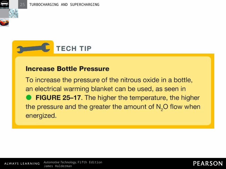
TECH TIP: Increase Bottle Pressure To increase the pressure of the nitrous oxide in a bottle, an electrical warming blanket can be used, as seen in - FIGURE 25–17 . The higher the temperature, the higher the pressure and the greater the amount of N2O flow when energized.
25 TURBOCHARGING AND SUPERCHARGING
Automotive Technology, Fifth EditionJames Halderman
© 2011 Pearson Education, Inc.All Rights Reserved
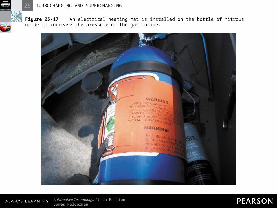
Figure 25-17 An electrical heating mat is installed on the bottle of nitrous oxide to increase the pressure of the gas inside.