tuomas seppänen automation improvements to …jultika.oulu.fi/files/nbnfioulu-201602111170.pdf ·...
TRANSCRIPT

DEGREE PROGRAMME IN COMPUTER SCIENCE AND ENGINEERING
Tuomas Seppänen
AUTOMATION IMPROVEMENTS TOLTE ENODEB USER PLANE SOFTWARE
INTEGRATION TESTING
Master’s ThesisDegree Programme in Computer Science and Engineering
January 2016

Seppänen T. (2016) Automation Improvements to LTE eNodeB User Plane Soft-ware Integration Testing. Degree Programme in Computer Science and Engineering,University of Oulu, Oulu, Finland. Master’s thesis, 64 p.
ABSTRACT
The LTE eNodeB base station software is composed of various interconnectedcomponents, which handle different functionalities. Integration testing is used totest the interfaces and interactions between the components when they are com-bined together. In agile software development new software component buildsare created frequently, which leads to a need for a quick and automated testingenvironment.
This thesis focuses on improving the level of automation in the LTE User Planesoftware integration testing continuous integration environment. Two differentsubjects, interface specification adaptation and test scenario configuration, areaddressed in this study. An automated system triggered by the continuous in-tegration platform is implemented to update the testing environment so that itcomplies with the latest interface specification. In addition, a new software toolis developed as a proof of concept for an alternative method for test script writ-ing and test case creation. The tool is used to create and configure test scenariosin a graphical user interface and to automatically generate test scripts from theconfiguration instead of writing the test scripts manually.
The operation of the automated adaptation system was observed for more thana year with over a hundred interface specification changes. Results show a sub-stantial reduction in processing time when comparing to the earlier manual pro-cess and no errors were detected in the output.
The new software tool for creating test scenarios achieves its goal. The toolenables the creation and configuration of basic test scenarios in the graphical userinterface and the generated test scripts can be executed successfully.
Keywords: test automation, continuous integration, software testing, agile soft-ware development, telecommunications

Seppänen T. (2016) Parannukset LTE eNodeB User Plane -ohjelmiston integraa-tiotestauksen automatisoinnissa. Oulun yliopisto, tietotekniikan tutkinto-ohjelma.Diplomityö, 64 s.
TIIVISTELMÄ
LTE eNodeB -tukiasema koostuu useasta toisiinsa yhteydessä olevasta kompo-nentista, jotka käsittelevät eri toiminnallisuuksia. Integraatiotestausta käytetäänkomponenttien välisten rajapintojen ja vuorovaikutusten testaamiseen. Ketteräs-sä ohjelmistokehityksessä uusia käännöksiä ohjelmistokomponenteista luodaanusein, mikä luo tarpeen nopealle ja automatisoidulle testiympäristölle.
Tämä diplomityö keskittyy parantamaan automaation tasoa LTE User Plane-ohjelmiston integraatiotestauksen jatkuvan integroinnin ympäristössä. Työssäkäsitellään kahta eri aihetta: rajapintamäärittelyihin mukautumista sekä testi-skenaarioiden konfiguraatiota. Automatisoitu järjestelmä, jonka käynnistää jat-kuvan integroinnin alusta, toteutetaan päivittämään testiympäristö noudatta-maan viimeisintä rajapintamäärittelyä. Lisäksi uusi ohjelmistotyökalu kehite-tään osoituksena vaihtoehtoisesta tavasta testikoodin kirjoittamiseen ja testita-pausten luomiseen. Työkalua käytetään graafisessa käyttöliittymässä testiskenaa-rioiden muodostamiseen ja konfigurointiin sekä testikoodin automaattiseen tuot-tamiseen konfiguraatioiden pohjalta käsin kirjoittamisen sijaan.
Automatisoidun mukautumisjärjestelmän toimintaa tarkkailtiin yli vuodenajan, jona aikana havaittiin yli sata rajapintamäärittelyiden muutosta. Tulok-set osoittavat huomattavan vähennyksen suoritusajassa verrattuna edeltäneeseenmanuaaliseen prosessiin. Järjestelmän tuotoksissa ei tarkkailuajanjakson aikanahavaittu virheitä.
Uusi ohjelmistotyökalu testiskenaarioiden luomiseen täyttää sille asetetun ta-voitteen. Työkalu mahdollistaa yksinkertaisten testiskenaarioiden luomisen jakonfiguraation graafisessa käyttöliittymässä. Työkalulla tuotetut testikoodit voi-daan suorittaa onnistuneesti.
Avainsanat: testiautomaatio, jatkuva integraatio, ohjelmistotestaus, ketterä oh-jelmistokehitys, tietoliikenne

TABLE OF CONTENTS
ABSTRACT
TIIVISTELMÄ
TABLE OF CONTENTS
FOREWORD
ABBREVIATIONS
1. INTRODUCTION 91.1. Scope of the Thesis . . . . . . . . . . . . . . . . . . . . . . . . . . . 10
2. LTE ARCHITECTURE 112.1. Brief History of Mobile Telecommunications . . . . . . . . . . . . . 112.2. Architectural Overview . . . . . . . . . . . . . . . . . . . . . . . . . 122.3. LTE Characteristics . . . . . . . . . . . . . . . . . . . . . . . . . . . 122.4. E-UTRAN . . . . . . . . . . . . . . . . . . . . . . . . . . . . . . . . 132.5. LTE Radio Interface Protocols . . . . . . . . . . . . . . . . . . . . . 14
2.5.1. Data Flow . . . . . . . . . . . . . . . . . . . . . . . . . . . . 152.5.2. The Physical Layer . . . . . . . . . . . . . . . . . . . . . . . 162.5.3. The Medium Access Control Layer . . . . . . . . . . . . . . 162.5.4. The Radio Link Control Layer . . . . . . . . . . . . . . . . . 172.5.5. The Packet Data Convergence Protocol Layer . . . . . . . . . 172.5.6. The Radio Resource Control Layer . . . . . . . . . . . . . . 17
3. AGILE SOFTWARE DEVELOPMENT 183.1. Scrum . . . . . . . . . . . . . . . . . . . . . . . . . . . . . . . . . . 193.2. Test-driven Development . . . . . . . . . . . . . . . . . . . . . . . . 213.3. Continuous Integration . . . . . . . . . . . . . . . . . . . . . . . . . 22
3.3.1. Basic Functionality . . . . . . . . . . . . . . . . . . . . . . . 233.3.2. Main Practices . . . . . . . . . . . . . . . . . . . . . . . . . 243.3.3. Benefits . . . . . . . . . . . . . . . . . . . . . . . . . . . . . 253.3.4. The Importance of Automation . . . . . . . . . . . . . . . . . 25
4. SOFTWARE TESTING 274.1. Testing Levels . . . . . . . . . . . . . . . . . . . . . . . . . . . . . . 274.2. Testing Methods . . . . . . . . . . . . . . . . . . . . . . . . . . . . . 284.3. Integration Testing . . . . . . . . . . . . . . . . . . . . . . . . . . . 29
4.3.1. Testing Approaches . . . . . . . . . . . . . . . . . . . . . . . 294.4. LTE UP SW Integration . . . . . . . . . . . . . . . . . . . . . . . . . 32
4.4.1. Interface Specification and Adaptation . . . . . . . . . . . . . 334.4.2. Automation . . . . . . . . . . . . . . . . . . . . . . . . . . . 35
5. AUTOMATION TOOL IMPLEMENTATION 37

5.1. Project Description . . . . . . . . . . . . . . . . . . . . . . . . . . . 375.2. Used Languages and Tools . . . . . . . . . . . . . . . . . . . . . . . 37
5.2.1. Python . . . . . . . . . . . . . . . . . . . . . . . . . . . . . 385.2.2. Bash . . . . . . . . . . . . . . . . . . . . . . . . . . . . . . 385.2.3. Subversion . . . . . . . . . . . . . . . . . . . . . . . . . . . 395.2.4. Jenkins . . . . . . . . . . . . . . . . . . . . . . . . . . . . . 39
5.3. Interface Adaptation Automation . . . . . . . . . . . . . . . . . . . . 395.4. The Message Template Parser . . . . . . . . . . . . . . . . . . . . . 42
5.4.1. Process Description . . . . . . . . . . . . . . . . . . . . . . . 435.4.2. Challenges . . . . . . . . . . . . . . . . . . . . . . . . . . . 45
5.5. The CSV Updater . . . . . . . . . . . . . . . . . . . . . . . . . . . . 465.5.1. Process Description . . . . . . . . . . . . . . . . . . . . . . . 465.5.2. Challenges . . . . . . . . . . . . . . . . . . . . . . . . . . . 48
5.6. The Scenario Configurator . . . . . . . . . . . . . . . . . . . . . . . 495.6.1. Requirements and Use Cases . . . . . . . . . . . . . . . . . . 505.6.2. The User Interface . . . . . . . . . . . . . . . . . . . . . . . 525.6.3. Process Description . . . . . . . . . . . . . . . . . . . . . . . 535.6.4. Challenges . . . . . . . . . . . . . . . . . . . . . . . . . . . 57
6. RESULTS AND DISCUSSION 586.1. Implementation Status . . . . . . . . . . . . . . . . . . . . . . . . . 586.2. Findings and Impact . . . . . . . . . . . . . . . . . . . . . . . . . . 586.3. Limitations . . . . . . . . . . . . . . . . . . . . . . . . . . . . . . . 596.4. Future Work . . . . . . . . . . . . . . . . . . . . . . . . . . . . . . . 60
7. SUMMARY 61
8. REFERENCES 62

FOREWORD
This Master’s Thesis was done for Nokia Networks in an LTE UP SWi team. The topicof the thesis and research was devised during the summer of 2013 while working atNokia Networks as a summer trainee. The development of the resulted software andthe writing of the thesis document was done concurrently between October 2014 andJanuary 2016.
I would like to acknowledge Nokia Networks for the opportunity to write this thesis.Furthermore, I would especially like to express my gratitude to my instructors, Mr.Kristian Ruotsalainen and Mr. Matti Jutila from Nokia. Your guidance and supporthas been extremely valuable and helpful along the process. A special thanks is alsoin order for my team mates and co-workers in the LTE UP SWi team. Your feedbackand knowledge has helped to steer the development process in the right direction. Ialso want to thank Prof. Juha Röning for supervising this thesis and for his importantfeedback.
Finally, I would like to thank my parents and my beloved Petra for their support andencouragement during the writing of this thesis and throughout my studies.
Oulu, Finland, January 27, 2016
Tuomas Seppänen

ABBREVIATIONS
1G First Generation2G Second Generation3G Third Generation3GPP Third Generation Partnership Project4G Fourth Generation5G Fifth GenerationAMPS Advanced Mobile Phone SystemAPI Application Programming InterfaceARQ Automatic Repeat RequestASN.1 Abstract Syntax Notion OneATT Automated Testing ToolBTS Base Transceiver StationCI Continuous IntegrationCP Control PlaneCRC Cyclic Redundancy CheckCS Circuit SwitchingCSV Comma-Separated ValuesCU CSV UpdaterDL DownlinkEDGE GSM EvolutioneNodeB E-UTRAN Node BEPC Evolved Packet CoreEPS Evolved Packet SystemE-UTRAN Evolved Universal Terrestrial Radio Access NetworkGbps Gigabits per secondGPRS General Packet Radio ServicesGSM Global System for Mobile CommunicationsGUI Graphical User InterfaceHARQ Hybrid Automatic Repeat RequestHSDPA High Speed Downlink Packet AccessHSPA High Speed Packet AccessIDE Integrated Development EnvironmentIFS Interface SpecificationIP Internet ProtocolJSON JavaScript Object NotationkHz KilohertzL1 Layer 1L2 Layer 2L3 Layer 3LTE Long Term EvolutionLTE-A LTE-AdvancedMAC Medium Access ControlMbps Megabits per secondMIMO Multiple Input Multiple OutputMM Mobility Management

MME Mobility Management EntityMTP Message Template ParserNMT Nordic Mobile TelephoneOFDMA Orthogonal Frequency Division Multiple AccessPDCP Packet Data Convergence ProtocolPDU Protocol Data UnitPS Packet SwitchingRB Radio BearerRLC Radio Link ControlRNC Radio Network ControllerROHC Robust Header CompressionRRC Radio Resource ControlRRM Radio Resource ManagementSAE System Architecture EvolutionSAP Service Access PointSC Scenario ConfiguratorSC-FDMA Single Carrier Frequency Division Multiple AccessSCM Source Code ManagementSDU Service Data UnitS-GW Serving GatewaySUT System Under TestSVN SubversionSW SoftwareSWi Software IntegrationTB Transport BlockTBS Transport Block SizeUE User EquipmentUL UplinkUP User PlaneWCDMA Wideband Code Division Multiple AccessXML Extensible Markup LanguageXP Extreme Programming

9
1. INTRODUCTION
Long Term Evolution (LTE) is currently the latest Third Generation Partnership Project(3GPP) standard in radio network technologies, also referred to as fourth generation(4G) mobile communication technology. It succeeds Global System for Mobile Com-munications (GSM) and GSM Evolution (EDGE), also known as second generation(2G) technologies, and Wideband Code Division Multiple Access (WCDMA) andHigh Speed Packet Access (HSPA), also known as third generation (3G) technolo-gies. [1, pp. 1-2] The Evolved Universal Terrestrial Radio Access Network Node B(eNodeB) is the Base Transceiver Station (BTS) for LTE and provides a connectionbetween User Equipment (UE) and the core network. [2, p. 11]
The software in the eNodeB systems in Nokia Networks is a complex entity of var-ious embedded software components. The different software components provide andhandle different functionalities in the eNodeB system. The software components com-municate with each other and control entities via control messages. The software com-ponents are combined together to form the full eNodeB software for different hardwaredeployments. Software development is done using Agile methods such as Scrum, con-tinuously producing new software builds with incremental changes.
The eNodeB software is tested at a multitude of testing levels. Software componentsare tested internally with unit and component testing, and internal interfaces with othersystem components are tested by utilizing component stubs in the test environment.LTE User Plane (UP) Software Integration (SWi) is the first integration testing levelwhere complete software components are integrated and the functionality of the soft-ware is tested as a whole. LTE UP software components are integrated using a ‘bigbang’ approach and most of the testing is done using the black-box method. This lowlevel testing phase includes the Layer 1 (L1) and Layer 2 (L2) component software.Layer 3 (L3) control software is not included and is instead replaced by testing tools.Thus LTE UP SWi verifies and tests only the UP side of the LTE protocol stack.
The main purpose and goal of LTE UP SWi is to test and verify feature and interfacefunctionality at an early phase of the development. Testing utilizes testing tool soft-ware, various simulators and test UE hardware. As new software component builds areavailable, they are continuously integrated together in a continuous integration (CI) en-vironment. Testing is automated and test executions are triggered either periodicallyor when the eNodeB software components are changed.
Test cases and scenarios are configured with testing tool software using eNodeBinterface control messages, and test UE hardware settings and behavior. Before theimplementation done within the scope of this thesis, the eNodeB interface control mes-sages in the LTE UP SWi environment were created and maintained manually. Thiswas problematic as the interface specification is often modified to reflect the changesmade in the eNodeB software. When the interface is modified, the LTE UP SWi envi-ronment must adapt the modifications to be able to continue testing the latest software.
Maintaining and updating the control messages and the test environment manuallyis very slow and prone to human error. Interface changes can cause major delays andinterruptions in testing activity as tests are unable to execute successfully until thechanges are adapted. The manual process forced people to stop other, higher valuework and focus on the interface adaptation, causing an increase in the work effort

10
and delayed testing. This leads to longer CI feedback cycles, and delays in softwareintegration testing can impact the delivery of new features and software releases.
Interface message structure and content is also complex and not very readable. Asthe messages can contain thousands of configuration parameters affecting the function-ality of the eNodeB, mistakes either in control message change adaptation or parametervalue settings can be very harmful. Wrongly structured messages or incorrect parame-ter values can cause unexpected and unintended eNodeB behavior during the test cases.This can lead to unreliable test results as the test scenario might not be what the testerintended.
1.1. Scope of the Thesis
The scope of the thesis is to improve the level of automation in the LTE UP SWienvironment in order to shorten the CI feedback cycle length and to reduce the numberof human mistakes with the test environment. The main cause for delays in the CIfeedback cycle is the manual work regarding interface specification change adaptationin the control messages. As a solution, an automated system to generate up-to-dateeNodeB control messages and environment configurations is introduced. In addition,to make test scenario set-up easier and less prone to human mistakes, a new softwaretool Scenario Configurator is implemented and introduced as a proof of concept foran alternative way of creating test scenarios. Scenario Configurator enables the user toconfigure test scenarios and create eNodeB control messages in a graphical interfacerather than manually editing test scripts. Software created for this thesis has been donein a Scrum mode using a test-driven development (TDD) process.

11
2. LTE ARCHITECTURE
2.1. Brief History of Mobile Telecommunications
During the last 15 years, the number of mobile subscribers has increased at a hugespeed. In the year 2002, the amount of subscribers reached one billion and just sixyears later, in the year 2008, four billion. [3, pp. 1-2] By the time of the year 2013,the number has already exceeded six billion and is quickly reaching the average of onesubscription per person in the world [1, p. xiii].
First mobile telecommunication services became widespread in the early 1980s. Thefirst generation (1G) technologies, such as Nordic Mobile Telephone (NMT) and Ad-vanced Mobile Phone System (AMPS), were analog systems designed to support onlyvoice services. In the 1990s, 2G networks, mainly GSM, introduced digital mobilecommunications and therefore the opportunity for data services. Although GSM wasalso originally designed to carry voice traffic only, data capabilities were later added.The first major data service provided was text messaging (Short Message Services,SMS). GSM networks were initially able to reach peak data rates of 9.6 kbps. Higherdata rates, up to 0.236 Mbps, were eventually reached with General Packet Radio Ser-vices (GPRS) and EDGE. [1, pp. 2-3] [3, p. 4]
Until the advent of 3G networks, High Speed Downlink Packet Access (HSDPA),data usage was dominated by voice traffic. As HSDPA increased the data rates com-pared to 2G networks considerably, data usage started to increase substantially. As flatpricing schemes became more popular, data traffic volume quickly surpassed the voicetraffic. [3, p. 2]
The definition of 3GPP LTE started in 2004 with outlining of the targets. By lookingat the rate of increase in network capacity demands, it had already become clear thata new radio system was needed, even though HSDPA had not yet been commerciallylaunched. [3, p. 4] LTE performance targets were set higher compared to earlier net-work technologies by multiple factors. Spectral efficiency was set to be two to fourtimes better than with the latest High Speed Packet Access (HSPA) release. Downlink(DL) and uplink (UL) data rate targets were set at 100 Mbps and 50 Mbps respectively.Round trip time was aimed at under 10 milliseconds. 3GPP LTE was first introduced in3GPP Release 8. [3, pp. 4-5] [2, p. 11] [4] LTE 3GPP Release 8 has often been labeledas only ‘3.9G’ [5].
The latest standardized technology is LTE Advanced (LTE-A), which is an enhance-ment of the LTE standard. LTE-A was standardized by 3GPP in March 2011 in 3GPPRelease 10. LTE-A is considered as being true 4G [5]. It focuses on bringing highercapacity and is specified to have peak data rates of 1 Gbps in DL and 500 Mbps inUL in one cell. [6] [3, pp. 11, 19] A comparison of DL peak data rates between 3GPPmobile technologies is seen in Figure 1 [3, p. 8].
It is expected that in the year 2020 the total worldwide mobile traffic will reachmore than 127 exabytes, which is roughly 33 times more than in the year 2010. Over40 exabytes of mobile data was predicted for the year 2015. [7] With this in mind it isclear that mobile networks face an increasing challenge to keep up with the capacityperformance demands. Fifth generation (5G) network technologies are currently be-ing researched, but they are not yet standardized. Commercial deployment of 5G isexpected around the year 2020, providing speeds even higher than 1 Gbps. [8]

12
Figure 1: DL peak data rates of 3GPP technologies.
2.2. Architectural Overview
The LTE architecture is split into two distinct networks, the Evolved Universal Ter-restrial Radio Access Network (E-UTRAN) and the Evolved Packet Core (EPC), alsoreferred to as System Architecture Evolution (SAE) [2, pp. 11-12]. E-UTRAN con-sists of eNodeBs, which is the BTS for LTE. UEs, such as smartphones and laptops,communicate with the eNodeB. The eNodeB is directly connected to the EPC througha Mobility Management Entity (MME) for control plane (CP) signalling and a ServingGateway (S-GW) for user plane data [3, pp. 25-28]. The EPC is connected to an exter-nal network, such as operator services and the Internet, through a Packet Data NetworkGateway (P-GW), which is connected to the S-GW. The LTE architecture is presentedin Figure 2 [2, p. 11].
2.3. LTE Characteristics
Unlike previous 3GPP mobile network technologies, LTE has a flat architecture, whichmeans that the eNodeBs communicate directly with the core network [2, pp. 11-12].There is no Radio Network Controller (RNC) node and instead, RNC functional-ity is included in the eNodeB. This minimizes the number of network elements andmakes the network configuration simpler, allowing smaller round trip times and higherthroughputs [3, pp. 5-6]. LTE uses Orthogonal Frequency Division Multiple Ac-cess (OFDMA) for DL and Single Carrier Frequency Division Multiple Access (SC-FDMA) for UL. LTE supports transmission bandwidths up to 20 MHz and MultipleInput Multiple Output (MIMO) technology. Peak data rates are 150 Mbps when using

13
Figure 2: LTE architecture overview.
2x2 MIMO or 300 Mbps using 4x4 MIMO for DL and 75 Mbps for UL. Resourceallocation happens in the frequency domain with a resolution of 180 kHz resourceblocks. Unlike the previous mobile technologies 2G and 3G, LTE is based completelyon Packet Switching (PS). PS was chosen as the only domain since 3GPP specifiedLTE to use Internet Protocol (IP) as the key protocol for all services [9].
2.4. E-UTRAN
The eNodeB is the only node in the E-UTRAN. This means that the eNodeB is incontrol of all radio related functionality in the LTE network. In a typical operator net-work, eNodeBs are distributed throughout the coverage area in close proximity to theactual radio antennas. Functionally the eNodeB provides the E-UTRAN UP and CPprotocol terminations towards the UE, and relaying data between the radio connectionto the UEs and the IP based connectivity towards the EPC. The eNodeBs are inter-

14
connected with each other via the X2 interface and to the EPC via the S1 interface.The eNodeB has the responsibility for many CP functions, such as Radio ResourceManagement (RRM). This means that the eNodeB is responsible for controlling theusage of the radio interface, including resource allocation, prioritizing and schedulingtraffic, and monitoring the usage of the resources. The eNodeB has an important rolealso in Mobility Management (MM). The eNodeB decides itself whether handoversfor UEs between cells are needed based on its measurements of the radio signal leveland quality. A more detailed description of the functional split between the E-UTRANand the EPC is presented in Figure 3. [3, pp. 27-28] [10]
Figure 3: Functional split between E-UTRAN and EPC.
2.5. LTE Radio Interface Protocols
The LTE radio protocol architecture can be divided into Control Plane architectureand User Plane architecture. The CP protocol stack is responsible for transferringsignalling messages and the UP protocol stack for transferring application data. Thefunction of the LTE radio interface protocols is to establish, reconfigure and releasethe Radio Bearer (RB) that provides the means for transferring the Evolved PacketSystem (EPS) bearer. A bearer can be described as a pipeline or a path way for datathrough the network from one point to another. An EPS bearer is established betweenthe UE and the P-GW. A radio bearer is established between the UE and the eNodeBacross the radio interface. There are two types of radio bearers: Data Radio Bearers(DRBs) and Signalling Radio Bearers (SRBs). DRBs carry user data and SRBs carrythe CP messaging. Figures 4a and 4b present the E-UTRAN UP and CP protocolstacks. [2, pp. 209-214] [3, pp. 137-139] [10]The LTE radio protocol stack includes the physical layer (PHY), also known as
Layer 1 (L1). Included Layer 2 (L2) protocols are Medium Access Control (MAC),Radio Link Control (RLC) and Packet Data Convergence Protocol (PDCP). All L1 and

15
(a) User Plane protocol stack. (b) Control Plane protocol stack.
Figure 4: E-UTRAN protocol stack.
L2 protocols are part of both UP and CP. Layer 3 (L3) consists of the Radio ResourceControl (RRC) protocol, which is only part of the CP. [3, pp. 137-138]
2.5.1. Data Flow
The LTE data flow in E-UTRAN UP utilizes Service Data Units (SDUs) and ProtocolData Units (PDUs). Each layer in the UP protocol stack receives a SDU from an upperlayer, processes the data, adds a protocol header to form a PDU and passes it onto alower layer. Figure 5 illustrates the LTE data flow between UP protocol layers. [1, p.126]
Figure 5: LTE data flow.
In the DL data flow example of Figure 5, three IP packets from two radio bearersare processed. The data flow in UL transmission is similar, although reversed. ThePDCP layer receives an IP packet as the PDCP SDU, performs IP-header compression

16
and ciphering. Then a PDCP PDU is formed by adding a PDCP header, which carriesinformation required for deciphering in the UE. The resulted PDU is then forwardedto the RLC layer.
The RLC layer receives the PDCP PDU, which is now handled as the RLC SDU.The RLC protocol performs concatenation and/or segmentation of the RLC SDU intosuitable sized RLC PDUs. A RLC header is then added to all resulting RLC PDUs.The RLC header contains data for in-sequence delivery per logical channel in the UE.The header is also used for identification if RLC retransmission is performed. TheRLC PDUs are then forwarded to the MAC layer.
The MAC layer receives the RLC PDU. The MAC protocol multiplexes the receivedPDUs and adds a MAC header to form Transport Blocks (TBs). MAC SDU size de-pends on the Transport Block Size (TBS), which is determined by the instantaneousdata rate chosen by the link adaptation mechanism. The resulting TBs are then for-warded to the physical layer.
Finally, the TB is received by the physical layer. It adds a Cyclic Redundancy Check(CRC) to the TB for error detection purposes. The physical layer also performs codingand modulation of the data and eventually transmits the resulting signal over the airinterface. [1, pp. 126-127] [2, pp. 209-214]
2.5.2. The Physical Layer
The physical layer is the Layer 1 in the radio interface between the UE and the eNodeB.It has a key role in defining the capacity and performance of the network. The physicallayer communicates with the upper MAC layer through transport channels. It providesphysical layer processing, such as adding CRC, coding interleaving and modulation,and handles transmission and reception across the air interface. Modulation is appliedbefore the data is mapped onto the air interface resources. OFDMA is used for theDL and SC-FDMA for the UL. The physical layer uses resources entirely based ondynamic allocation of the shared resources instead of having user specific dedicatedresources. [2, pp. 210-212] [3, p. 83]
2.5.3. The Medium Access Control Layer
The MAC layer communicates with the upper RLC layer through the logical channelsand maps them to the transport channels for the physical layer. The MAC layer handlesand is responsible for prioritizing and multiplexing the data received from the logicalchannels. It also performs Hybrid Automatic Repeat Request (HARQ) retransmissionsand DL and UL scheduling. Link adaptation for both DL and UL is also done in theMAC layer, for example selecting a suitable modulation scheme and TBS. [1, pp. 128-135] [2, pp. 210-212] [3, pp. 139-143]

17
2.5.4. The Radio Link Control Layer
The RLC layer communicates with the upper PDCP layer through a Service AccessPoint (SAP) [10]. The RLC protocol can operate in three modes: Transparent Mode(TM), Unacknowledged Mode (UM) and Acknowledged Mode (AM).
In the TM mode, received PDUs pass through the RLC layer without adding anyheaders. The TM mode can be used only for services that are not sensitive to the orderof delivery or do not use physical layer retransmissions.
In the UM mode, the RLC layer provides more functionality. The RLC protocol pro-vides in-sequence delivery if HARQ operations have occurred in the lower level layers.Received PDUs are also segmented or concatenated and RLC headers are added.
In the AM mode, the RLC layer provides the same functionality as the UM mode,but also adds the possilibity of Automatic Repeat Request (ARQ) retransmissions ifPDUs are lost in the lower layers. [1, pp. 127-128] [3, pp. 143-145]
2.5.5. The Packet Data Convergence Protocol Layer
The PDCP layer provides header compression using Robust Header Compression(ROHC) and ciphering for the user plane data. It also provides ciphering and in-tegrity protection for CP messaging. Header compression is not performed for CPdata. Header compression is essential as the large overheads in the headers gener-ated by higher layers can waste valuable air interface resources and thus lead to worseperformance [2, pp. 209-211].
2.5.6. The Radio Resource Control Layer
The RRC layer is only part of the CP. The RRC messages are a significant part ofthe control information exchanged between the UE and the eNodeB. RRC messagesuse the Abstract Syntax Notion One (ASN.1) protocol format and they are transmittedonly on SRBs. The RRC protocol is responsible for many radio resources functionsand handles bearer and UE connections between the UE and the eNodeB. In LTE, thereare only two UE states for RRC connectivity: RRC_IDLE and RRC_CONNECTED.
In the RRC_IDLE state, the RRC connection is not established, and the UE is mon-itoring the paging channel for incoming calls and acquiring information from the cur-rent and neighboring cells. In the RRC_CONNECTED state, the RRC connection isestablished and data flow is active between the UE and the eNodeB. [3, pp. 146-147]

18
3. AGILE SOFTWARE DEVELOPMENT
Traditionally, software development approaches, such as the waterfall model, havestriven to anticipate and predict all requirements and finalize the project plan at thebeginning of the process. This is done for the purpose of trying to reduce changes inthe later stages of the development process as they are usually very costly. Traditionalsoftware development methods are also linear by nature and do not define how to re-act to unpredictable situations or problems during any of the project phases. Theseapproaches have been found to fit poorly in the modern business culture where situa-tions change rapidly and failing to follow up on these changes is considered a businessfailure [11] [12].
Figure 6: Waterfall model.
Agile software development is an umbrella term for a collection of different softwaredevelopment methods. The term groups together a philosophy with a set of guide-lines [13, pp. 65]. Popular agile methods include for example Scrum and ExtremeProgramming (XP). Rather than avoiding and rejecting changes during the softwaredevelopment process, agile methods aim to embrace them and instead focus on re-ducing the cost. Highsmith and Cockburn define agility as being about creating andresponding to change [11].The main principles and cornerstones of agile methods were conceived in February
2001, when 17 software industry experts calling themselves the Agile Alliance joinedtogether. They came up with a document called the Agile Manifesto. [14, pp. 4] Itstates the following [15]:
“We are uncovering better ways of developing software by doing it and helpingothers do it. Through this work we have come to value:
Individuals and interactions over processes and toolsWorking software over comprehensive documentationCustomer collaboration over contract negotiationResponding to change over following a plan
That is, while there is value in the items on the right, we value the items on theleft more.”

19
Agile software engineering emphasizes customer communication and satisfactionand encourages rapid, incremental software delivery. Agile methods see the customerfavourably as part of the development team to make communication more effective.Project plans should be made flexible and possible problems and uncertainties duringthe project should be taken into account. As also mentioned in the manifesto, Jacobsonputs weight on individual work and cooperation within a team. [16] Intermediate workproducts, such as documentation, are de-emphasized and constant software deliveriesare considered more valuable to the customer [13, pp. 67].The agile process is driven by scenarios from the customer, which are descriptions of
requirements. Plans are not thought as set in stone and are subject to change. Differentagile methods have different ways of working to comply with the guidelines, but theyall follow the same core principles. Figure 7 displays the difference between traditionaland agile software development methods regarding the cost of change as a function oftime in development [13, pp. 67-72].
Figure 7: Cost of change as a function of development progress in time.
3.1. Scrum
Scrum is a widely used agile software development method. It was invented by JeffSutherland in the early 1990s. Scrum has been later on developed further by KenSchwaber and Mike Beedle. Scrum conforms well to the agile philosophy and princi-ples described in the agile manifesto. [13, pp. 82-83] It enhances the traditional itera-tive and incremental development approach that was first created and documented byMatthew Pittman and later developed by Grady Booch. Scrum is considered more ofa framework of practices rather than a prescriptive process as it does not dictate anddescribe what should be done in every situation. [12] [17]The most significant and central parts of the Scrum process are sprints. Sprints are
process patterns, which consist of work units towards a specific requirement, feature or

20
a task and have a predefined length in time. A sprint period is usually one to four weekslong. In the beginning of a sprint, these work items are taken from a product backlogin a sprint planning meeting. The product backlog is a list of all the requirements andfeatures that have value to the customer. The product owner prioritizes the work itemson the backlog and maintains and updates it if necessary, but this is not done during asprint to provide the Scrum team a stable environment. Scrum emphasizes team self-organization and self-management. Teams are cross-functional, meaning that the teammembers include people from all fields of expertise that are required to fully complete abacklog item within the team. The Scrum process is presented in Figure 8. [13, pp. 82-84] [12] [17]
Figure 8: The Scrum process with a 30-day sprint.
In the course of a sprint, the team plans, develops, tests and finally delivers the fin-ished work item in a fully functional software increment. Short, typically 15-minuteScrum meetings are held daily. All Scrum team members participate and share infor-mation about their progress. As Pressman explains, three questions are specificallyanswered one-by-one by all Scrum team members: [13, pp. 84]
• What did you do since the last team meeting?
• What obstacles are you encountering?
• What do you plan to accomplish by the next team meeting?
The team is led by a Scrum master, who provides guidance and coaching to theteam. The Scrum master is also responsible for solving issues that disturb the workand ensuring that Scrum practices are followed. All Scrum meetings are facilitated bythe Scrum master, sometimes joined by the product owner. At the end of every sprint,a sprint retrospective meeting is held by the team. During this meeting, the team looksback at the ending sprint to revise and reflect on the Scrum practices. Conclusionsmade as a result of this meeting can then be used to improve coming sprints. [17]The main difference in the way of working between traditional approaches and
Scrum is that traditional approaches have defined development processes while Scrumsprints are empirical. This means that in Scrum the sprint process is mostly unpre-dictable. Traditional processes have well-defined inputs and outputs and the way of

21
working is known explicitly. In Scrum, sprints are nonlinear and flexible and they aretreated as a black box. This approach supports and encourages creativity in the teamas the process relies on the skill and ingenuity of the individual members. [12]
3.2. Test-driven Development
Test-driven development (TDD) is a software development strategy and often used inagile development processes. In TDD, test cases are written and executed before theactual production code is created. The TDD process is done in fast iterations, wherethe code is developed in small increments, usually one subfunction at a time. Test casesfor small subfunctions, or in other words units, are called unit tests. Traditionally theunit tests have been written after the production code in a time frame ranging from acouple of minutes to many months. [18] [13, pp. 826-827]Before the production code can be written, the developer writes a unit test case for
the production code functionality. As the unit test tests code that has not been writtenyet, it should fail. Subsequently, the production code is written to make the unit testpass. If the test case passes, both the test case and production code are refactored whilecontinuously running all test cases to ensure that the code still works. This work flowis repeated until all requirements are satisfied and there are no more test cases to becreated. The TDD process flow is presented in Figure 9. [13, pp. 826-827] [18]
Figure 9: Test-driven development process flow.
The main point in TDD is software design. Writing the tests defines requirementsfor the code and when writing the test case, the developer decides what the productioncode should do. This step is part of the analysis and planning. As Janzen and Saiedianpoint out, TDD is often misunderstood as being mainly about testing and not design.

22
Some blame can be put on the name test-driven development, which includes the wordtest but not the word design. Secondly, most studies have focused on the externalquality of the code, meaning defects, and productivity. This focus is valid and useful,but the primary aspect of design in TDD, affecting mostly the internal quality of thesoftware, is often missed. [19]
Studies have shown TDD to improve both the external and the internal quality of thesoftware. In 2005, Janzen and Saiedian combined results from several different studiesboth in industry and academia. These studies focused on the external quality andshowed improvement in most of the cases. [18] In another study in 2008, Janzen andSaiedian focused more on the internal quality factors of the software such as code size,complexity and coupling. The study compared results from coding tasks performed bytest-first and test-last approaches. The research data showed that test-first programmerswrote smaller and simpler code than their test-last counterparts. However, the studydid not a reveal clear difference regarding code cohesion and coupling. [19]
3.3. Continuous Integration
In traditional linear software development models, software integration has usuallytaken place at the end of the project. This has often been a huge and daunting taskcausing major problems in software quality, which in the end phase of the project arevery costly and can lead to delays in delivery. The importance and difficulty of soft-ware integration is tied to the complexity and size of the project. In his book, Duvalleven calls this phase of development “integration hell.” Integration might not be a bigissue in small one-person projects, but adding even one more person to the projectincreases the significance of integration greatly as the ability of the software compo-nents to work together has to be ensured. The approach of continuous integration (CI)addresses these difficulties and alleviates them by introducing a practice for rapid andearly integration. [20, pp. xix-xxii]
CI is a practice for software development where the work of individual developersis merged together frequently, in most cases many times a day. Each integration in-crement is tested and verified by an automated system, which builds the software andruns tests. This allows the earliest possible detection of integration errors. Accordingto Fowler, many teams have found this process to greatly reduce integration issues andto allow more rapid development of a cohesive and stable software. CI originated fromthe core practices of Extreme Programming and is nowadays widely used in all agileprocesses. [21]
CI and TDD are complementary practices to each other. Software created withTDD’s test-first approach is inclined to be well designed and therefore easy to inte-grate with the whole project. A system where new code is always tested and integratedearly in small increments automatically ensures that the software grows in a composedand controlled way and that the software is always near a ready-to-release state. In thecase of embedded software, using CI and TDD can distinguish software and hardwareproblems from each other as these processes promote a strong separation of differentsoftware areas. [22]

23
3.3.1. Basic Functionality
As a prerequisite, CI assumes the usage of a source code management (SCM) system.Other than that, the CI practice itself does not require any specific tools to be used. CIdoes not necessarily need to be an automated process to fulfill its purposes. A man-ual approach to integration with an automated build can work well in many situations.However, as the main purpose of CI is to provide rapid feedback and automation pro-vides great benefits, a CI server is often used to automate the CI practices. Figure 10presents the typical components of a CI system. [20, pp. 3-8] [21]
Figure 10: CI system components.
A typical CI development scenario begins with the developer checking out a localworking copy from the version control repository of the mainline branch. The devel-oper then writes the automated tests and the production code on the local machine. Af-ter the changes are done, the software is built and tested on the development machine.If the software builds and tests execute without errors, the developer can commit thelocal changes to the repository. If errors occur, the code is fixed and rebuilt and testsre-executed locally.Once the changes are committed to the repository, the CI server polls the reposi-
tory periodically to detect changes. The server then checks out the latest revision fromthe repository and integrates it with the rest of the software. The CI system usuallyincludes multiple build servers and test environments, which the CI server commandsand uses. The integrated software is then built and tested by the CI server and feedbackis generated from the results. If errors are detected, the main task of the developer isto fix the errors as soon as possible. This means that integration errors are detected atthe earliest possible phase and by integrating the software incrementally and rapidly,

24
the developers can easily pinpoint the code responsible for breaking the software. Fig-ure 11 presents a typical work flow of a CI scenario. [21]
Figure 11: Typical CI software development scenario.
3.3.2. Main Practices
To enable the CI working process described in the previous section to work effec-tively, there are a number of practices that need to be in place. First, a software projectshould use and maintain a source code repository using an SCM system. The repos-itory should have a mainline branch, usually called trunk, and keep the use of otherbranches to a minimum. The repository should contain everything that is required tobuild the software, including test scripts, databases, install scripts and even integrateddevelopment environment (IDE) configurations. Fowler coins a rule of thumb, whichstates that a developer should be able to take a clean workstation, check out the repos-itory and be able to build the system completely with only minimal work needed toprepare the workstation. [21]When code is committed to the repository, the CI system should automatically in-
tegrate and build the software. Building the software can be automated by a script ora series of scripts, which can then be run by a CI server. When the build is finished,it should be automatically self-tested. This means that a test suite of unit tests shouldbe automatically run for every build. This has great benefits and synergy with TDD ascode produced with TDD is often very well self-tested. However, it is not a require-ment of CI to use TDD as CI does enforce just as strong a rule for self-testing as TDDdoes. [21] [23] [24]The developers should commit to the mainline at least once per day, preferably many
times per day, but only if the code is not broken. The code should be built and testedon a local workstation before committing to the mainline. Committing many times aday ensures that the integration is happening with small changes. This, again, meansthat bugs are caught early and debugging is easy as changes are small and erroneouscode is easy to locate. [21] [24]As the code is being integrated and built with every commit, it is important that the
building itself is fast. Fowler states that a good guideline for maximum build lengthis ten minutes. [21] Fast builds ensure that the time between the developer’s commitand feedback from CI, the feedback cycle, is kept as short as possible. Testing can bealso split into many phases. With every commit, a fast test suite should always be run.

25
Passing this first build test enables the developers to continue working on the mainlinewith confidence. After the commit build, other more extensive and slower tests can betriggered to run in parallel using the executables from the commit build. In contraryto commit build failures, secondary test failures do not necessary require immediatefixing of the errors, although it is recommended to fix them also as fast as possible.
An important aspect of CI is also the testing environment. Optimally the testingshould happen in the production environment, with the same hardware and configura-tions as the actual product. If testing is done only in a testing environment, there is arisk of missing issues and bugs that are specific to the production environment.
A CI system often has more than one test environment and machine. An automaticdeployment of builds and tests should be in place. One environment is usually ded-icated for the commit build tests and other environments can run the secondary orregression tests. The deployment can usually be automated with the CI server.
As main point of CI is feedback and communication, there must be a mechanism inplace for the developer team to see what is happening easily. The state of the systemand changes made to the code should be always visible. One of the most importantthings to monitor is the state of the mainline commit build. Many CI servers provideviews to display this information for example on a web page. This web page can bedisplayed in the team room at all times. Email is also a good way for the feedback toreach the developers. [21] [20, pp. 10-12, 220]
3.3.3. Benefits
The greatest value and benefit of CI comes from the reduced risk. CI completelyeliminates the fear of the “integration hell” as there is no longer a long and undefinedperiod of integration at end of the project. CI enables the developers to have a constantknowledge of the state of the system. Problems are detected and fixed early and thehealth of the system is constantly being measured and monitored via automated tests.The developers also have to make less assumptions in the code. [21] [20, pp. 29-32]
The automated CI process allows the developers to concentrate on the actual workrather than executing repetitive processes such as code compilation, testing and inspec-tion. CI reduces or even completely eliminates these processes from the manual workof the developers. CI ensures that the process is ordered and runs exactly the same wayevery time, thus reducing possible human errors.
Using a CI process can also enable the release of a deployable software at any giventime. By keeping the mainline code base always stable and error free, the software isalways in a complete state. This is especially important when working in with an agilemethod such as Scrum, in which after every sprint a fully working software incrementshould be delivered. [20, pp. 31]
3.3.4. The Importance of Automation
In general, using automated systems to replace manual work eliminates human errorsand frees people to do more higher-value work. This is also the case with CI withadditional benefits. Compared to manual CI activities, automated CI brings better effi-

26
ciency and frequency. An automated system can also ensure that the activities are donein a clean environment, always following the same steps and settings. This reduces theneed for assumptions and thus leads to better decision making.
Automation contributes a lot to the speed of the feedback from CI. By increasing thelevel of automation in the CI system, the time between the changes and the feedbackis usually reduced. In other words, the feedback cycle of CI is shortened. Duvallintroduces four steps that can be applied to almost every activity regarding a softwareproject. [20, pp. 29-32, 34]
• Identify — Identifying a manual process that can be automated.
• Build — Creating a script or a small program to automate the process. Theautomation should be repeatable and unchanging.
• Share — Storing the script or program to the version control repository. Thisway it can be used by everybody and be applied across the project.
• Make it continuous — Include the automated process into the CI process so thatit is executed by the CI server every time a change is detected.

27
4. SOFTWARE TESTING
The goal of software testing is to reveal errors that were made when designing andimplementing the software [13, pp. 449]. Myers [25, pp. 5-10] puts weight on the re-mark that testing should not be primarily thought of as a demonstration of the correctfunctionality of the software. Instead, it should be assumed that the tested softwarecontains errors and testing should be done to find as many faults as possible. The find-ing of an error adds value to the software and therefore furthers the progress towardsthe fully functional program.Software errors are caused by bad software quality. A software error can be catego-
rized as a source code error, procedural error, an error in the documentation or a dataerror. In almost all of the cases these errors are caused by humans and can be caused bya multitude of reasons. These reasons include incorrect requirement definitions, com-munication failures, logical errors and deviations from the requirements, documenta-tion or given instructions done either accidentally or deliberately. [26, pp. 19-24]
4.1. Testing Levels
Software testing is categorized into different levels corresponding to a software devel-opment phase or activity. Tests on most of the testing levels can be executed only aftera certain part of the software is written. However, tests for all levels can be designedand created throughout the software development process. Figure 12 displays the Vmodel, presenting the different software development activities and their correspond-ing testing levels. The information needed to implement a test is usually derived fromthe corresponding software development activity. [27, pp. 5-8]
Figure 12: The V model of software development phases and testing levels.
Acceptance testing is used to verify that the software meets the requirements set bythe customer in the early requirements analysis phase and during the project. Thisrequires that the people involved in the testing have strong knowledge of the domain.[27, pp. 5-6] For this reason, acceptance testing is usually performed by the customeror the end user [25, pp. 144].System testing focuses on finding out whether the system as a whole functions as
intended. This testing phase correlates with the architectural design phase, in which

28
the included system components are chosen and their connections and functions arespecified. System testing verifies that the software fulfills its objectives. This testinglevel usually reveals design and specification faults. Finding a a low-level softwareerror in system testing can be very costly. [27, pp. 6] [25, pp. 130]Integration testing assesses whether the interfaces between different software mod-
ules inside the subsystem work correctly. Software modules are assumed to functioncorrectly otherwise. Integration testing is commonly done with a part of the system.Often only a few of many components are tested together, which does not require thewhole system to be complete. [27, pp. 6, 217] Integration testing can be approachedwith many different testing methods and strategies, which are explained in more detailin section 4.3.Module testing is used to verify individual software modules. Modules are a collec-
tion of software units, the smallest possible subroutines and subprograms in the code.Module testing verifies that these units work and interact correctly together in isolationfrom the rest of the system. [27, pp. 6]Software code is produced in the implementation phase, which is tested in the unit
testing phase. Unit testing is designed to verify the functionality of the individualsoftware units and is considered the lowest level of testing. [27, pp. 7]
4.2. Testing Methods
Software testing techniques are usually divided into two prevalent testing methods:black- and white-box testing. These methods describe how the system under test (SUT)is viewed when designing the test cases. Any software product can be tested andverified with one of these two strategies. [13, pp. 484]In black-box testing, the testing only applies to the interface of the system as the
internal behavior and structure of the software is either unknown or disregarded. TheSUT is viewed only externally, as a black box. Black-box testing focuses only tofind situations in which the system behaves differently from what is specified. Thismeans that the test cases and data are derived from the specifications of the software,rather than from the internal composition. For the test cases, sets of inputs are definedfor the SUT and the output is verified for each input. The goal of the testing is toverify behavior with every possible input, but in many cases this is impractical or evenimpossible as the amount of possible inputs can be extremely high. This technique iscalled exhaustive input testing. Figure 13 presents the black-box approach. [25, pp. 9-10] [13, pp. 495]
Figure 13: Black-box testing approach

29
In white-box testing the internal structure of the software is known and test cases arebuilt based on that knowledge. The data for the test cases is derived from the logic ofthe software. The goal in white-box testing is to test every possible logical path andstatement in the software, as opposed to testing inputs in black-box testing. Similarto exhaustive input testing, exhaustive path testing is also often impractical or evenimpossible to implement due to the massive amount of possible combinations of theprogram flow. Figure 14 presents the white-box approach. [25, pp. 11-13] [13, pp. 485]
Figure 14: White-box testing approach
4.3. Integration Testing
Quality of the final software product relies heavily on the quality of the individualsoftware modules that combined together create the system. Not only do modulesneed to be well-tested on their own, they need to be tested when integrated together.Interfacing modules with each other can experience a multitude of issues. For exam-ple, data loss over an interface can occur, unforeseen effects and incorrect behavior ofcombined subfunctions can happen. Integration errors are usually caused by insuffi-cient specifications, incorrect implementation of the interfaces, resource managementor needed properties. Integration testing is designed to uncover these errors in the inter-facing of the modules. Modules that are being integrated are already unit and moduletested. [28] [13, pp. 459]
4.3.1. Testing Approaches
There are two kinds of approaches to integration testing: incremental and nonincre-mental testing or big-bang testing. These strategies describe how the modules in thesystem are integrated in the testing. In the nonincremental ‘big-bang’ strategy the soft-ware modules are all integrated together at once and testing is done with the completesystem. The opposite strategy, incremental testing, dictates that the software is con-structed and tested in smaller increments until the whole software is integrated. Incre-mental testing can be performed using two primary strategies: top-down and bottom-uptesting. [28] [26, pp. 182] [13, pp. 459]Big-bang testing is usually discouraged if the integrated software is large as the
isolation of the causes of the errors can be difficult [13, pp. 459]. Interface errors andprogramming errors in modules are often detected later than in incremental testing.

30
However, nonincremental testing usually uses less computational time and allows moreparallel actions than incremental testing as all modules are tested simultaneously. [25,pp. 107-108]Doing integration testing using an incremental testing strategy is considered to be
superior to nonincremental testing. Interface errors can be found earlier which directlymeans lower costs for repairing such an error. As hardware costs have been decreasingand simultaneously the computational power and capabilities have been increasing, theimportance of saving on the hardware has been diminishing. The two most prevalentincremental testing strategies are top-down and bottom-up. Both strategies are usedto test a software with a hierarchical module structure. In the top-down strategy, thehighest level module is tested first and testing continues down the hierarchy with thelowest level modules being the last modules that are tested. In the bottom-up approach,the testing order is the other way around. Lowest level modules are tested first and thehighest level main module is tested last. [25, pp. 108-109] [26, pp. 182]Figure 15 displays an example testing sequence with a top-down strategy. Testing
is done in six phases and it starts from the top of the hierarchy. In stage 1, module11 is unit tested and in stage 2 modules 9 and 10 are integrated with module 11 andintegration test A is performed. In stage 3 the sub-system of integration A is integratedwith module 8 and integration test B is executed. Modules 6 and 7 are integrated withB and integration test C is run in stage 4. Final actual integration test D is performedin stage 5 in which modules 1 and 2 are integrated with C. In the final stage 6, modules3, 4 and 5 are integrated with D and a system test is performed. [26, pp. 182-185]
Figure 15: Illustration of top-down testing.

31
The sequence displayed in Figure 15 is only one example of a possible top-downtesting path. The order of integrated and tested modules is dictated only by the rulethat requires that at least one of the modules calling modules ought to have been testedearlier. Top-down testing requires stubs, or so-called dummymodules, to replace lowerlevel modules, which are not yet available when performing unit or integration tests.Stubs are used to simulate the functionality of modules, which have not yet been de-veloped. [25, p. 110] [26, pp. 185] For example, in Figure 15 in stage 2, the testing ofmodule 8 requires that modules 1 and 2 are substituted with stubs to enable the testing.Figure 16 displays an example testing sequence with a bottom-up strategy. Testing
is done in four phases and it starts from the bottom modules. In stage 1, modules 1to 7 are unit tested and in stage 2 modules 1 and 2 are integrated with module 8 andintegration test A is performed. In stage 3, modules 3, 4, 5 and 8 are integrated withmodule 9 and modules 6 and 7 are integrated with module 10. Two integration tests, Band C, are executed. In the final stage 4, B and C are integrated with top-level module11 and a system test is performed. [26, pp. 182-183]
Figure 16: Illustration of bottom-up testing.
Like in top-down testing, the order of tested modules can vary. The only rule thatneeds to be followed is that all the modules called from the tested module need tohave been tested earlier. In bottom-up testing, driver modules, like stubs in top-downtesting, are needed to substitute higher-level modules that are not yet developed oravailable. Drivers contain test inputs, call the tested modules and handle the module’soutput. [26, pp. 182-185] [25, p. 116-117] For example, in stage 2 in Figure 16, module9 needs to be substituted with a driver module when testing module 8.Both incremental testing strategies have their advantages and disadvantages. Bottom-
up is considered to be easier to perform as top-down requires the development of mul-tiple stubs, which can be quite complicated modules themselves. Driver modules areusually much simpler and thus require less work. The biggest disadvantage of bottom-up testing is that the functionality of the entire program cannot be tested and displayeduntil the late stages of the testing, although this might not be as crucial if most flawsoccur toward the bottom of the program hierarchy. On the other hand, the biggest

32
advantage of top-down testing is that the main program functionality can be demon-strated in a very early stage after the upper-level modules have been completed. It isnot often clear which strategy should be preferred and used. Usually the best way is toweigh the pro and con factors against the requirements and needs of a particular soft-ware. Many developers also determine the strategy based on the chosen developmentmethod, being either top-down or bottom-up. [26, pp. 185-186] [25, p. 118-119]
4.4. LTE UP SW Integration
LTE UP SWi in Nokia Networks is a low level integration testing phase in which theLTE UP software components are integrated. Integration is done with a ‘big bang’approach, where all LTE UP software components are integrated and coupled togetherat the same time to form the LTE UP software part of the eNodeB system. However,the tested software does not include all components of the full eNodeB system. Forexample, the LTE CP software is not included and instead, the CP functionality isreplaced with the testing equipment and software. Some eNodeB software componentsare not included in the software build at all and some are replaced by component stubsto provide enough functionality to enable the LTE UP software testing. The completeeNodeB software with all software components is integrated and tested at a highertesting level. The integration testing of the whole eNodeB software is done using abottom-up testing strategy with multiple sub-system integration phases, LTE UP SWibeing one of them. LTE UP SWi often includes both black- and white-box testing.Testing in LTE UP SWi is automated in a CI environment using a Jenkins CI server.
All control messages and build and test scripts are stored in a Subversion (SVN) sourcecontrol repository. The test environment consists of multiple workstations, which areall paired with real production hardware. UE functionality is simulated with a UEsimulator hardware. Figure 17 presents the LTE UP SWi test environment.
Figure 17: The LTE UP SWi test environment.
The eNodeB system is controlled by eNodeB control messages. In normal operation,these control messages would be sent by L3 CP software. However, as the L3 CP andhigher layer software and functionality are absent in the software builds used in LTEUP SWi, the control messages are sent by a testing tool. The control messages are used

33
to configure the eNodeB to a specific testing scenario with a specific parametrization.There are three types of control messages: request, response and indication. Requestsare messages sent to the eNodeB, to which the eNodeB replies with a response mes-sage. Every request message has a corresponding response message, which containsdata specific to the request. Response messages also indicate if the sent request dataand structure was valid. Together with different kinds of system logs, data from theresponse messages is used to verify the functionality of the eNodeB. The eNodeB testsetup is displayed in Figure 18.
Figure 18: eNodeB test setup.
The main component of the test environment is the test PC, which hosts the testscripts and runs the testing software tool, referred to in this document as AutomatedTesting Tool (ATT). The ATT is internally developed and maintained by Nokia Net-works and intended for BTS software and hardware testing. It includes a frameworkfor creating and executing test scripts, commanding the UE simulator and sendingeNodeB control messages. It utilizes its own proprietary scripting language and for-mat for the control messages. The format of the control messages is explained furthertogether with the interface specification in subsection 4.4.1. All communication be-tween the devices is done via Ethernet. The ATT replaces the L3 RRC functionality ofthe eNodeB software.
4.4.1. Interface Specification and Adaptation
In LTE UP SWi, the eNodeB functionalities, features and interfaces are tested by usingeNodeB control messages. Every component in the system has an application program-ming interface (API), which is specified in an interface specification (IFS). Interfacespecifications are Nokia internal documents, in which the component API is explainedand available control messages and their contents are defined.Messages consist of a header and a payload. The header contains information about
the receiver, sender and metadata about the message, for example message type. Thepayload part includes the actual content of the message. The content of the message isbased on the IFS, where the message is specified.The ATT utilizes message templates, which are defined in its own custom format.
As the actual messages are just bit sequences, message templates provide a more user-
34
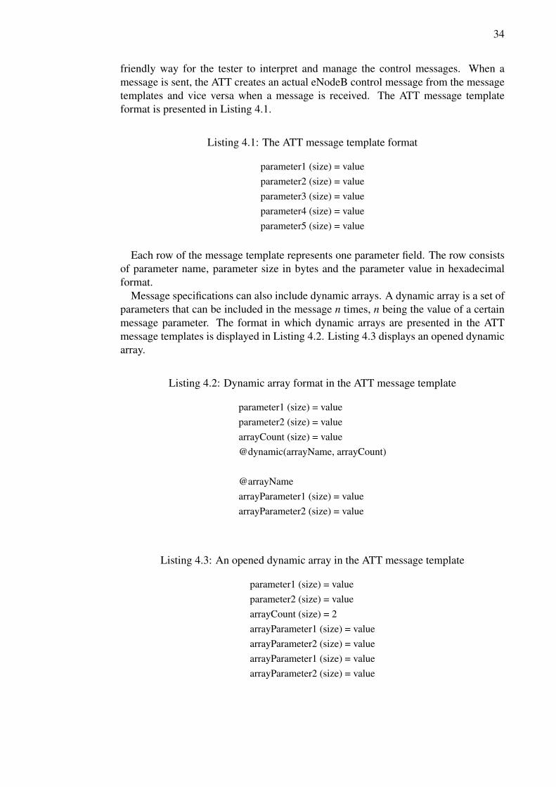
friendly way for the tester to interpret and manage the control messages. When amessage is sent, the ATT creates an actual eNodeB control message from the messagetemplates and vice versa when a message is received. The ATT message templateformat is presented in Listing 4.1.
Listing 4.1: The ATT message template format
parameter1 (size) = valueparameter2 (size) = valueparameter3 (size) = valueparameter4 (size) = valueparameter5 (size) = value
Each row of the message template represents one parameter field. The row consistsof parameter name, parameter size in bytes and the parameter value in hexadecimalformat.
Message specifications can also include dynamic arrays. A dynamic array is a set ofparameters that can be included in the message n times, n being the value of a certainmessage parameter. The format in which dynamic arrays are presented in the ATTmessage templates is displayed in Listing 4.2. Listing 4.3 displays an opened dynamicarray.
Listing 4.2: Dynamic array format in the ATT message template
parameter1 (size) = valueparameter2 (size) = valuearrayCount (size) = value@dynamic(arrayName, arrayCount)
@arrayNamearrayParameter1 (size) = valuearrayParameter2 (size) = value
Listing 4.3: An opened dynamic array in the ATT message template
parameter1 (size) = valueparameter2 (size) = valuearrayCount (size) = 2arrayParameter1 (size) = valuearrayParameter2 (size) = valuearrayParameter1 (size) = valuearrayParameter2 (size) = value

35
The ATT message templates are stored in text format in the LTE UP SWi SVNrepository. Different parameter sets for the message templates are stored in comma-separated values (CSV) files, which mirror the structure of the message templates. Foreach message template there is a corresponding CSV file. The CSV files are also storedin the SVN repository. The message templates and the parameters from the CSV filesare read by the ATT and the parameter values can then be applied to the messages. Testscripts have also references to parameters read from the CSV files to allow reading ormodifying of the parameters during a test case. Example of the used CSV file structureis displayed in Listing 4.4.
Listing 4.4: Example of the CSV file structure
MessageName_firstParameter,0,0,0,0,0,0MessageName_secondParameter,1,0,1,0,1,0MessageName_thirdParameter,FF,FF,FF,FF,FF,FFMessageName_parameterWithSameName,0,0,0,0,0,0MessageName_parameterWithSameName_2,A,A,A,A,A,AMessageName_parameterWithSameName_3,4C,2A,CC,EF,7,2
Each row in the CSV files represents one parameter and its values. First field con-tains the message and the parameter name joined with an underscore. The rest of thefields contain the parameter values in hexadecimal format. The amount of values de-pends on the type of the message and the amount of different scenarios stored in theCSV. Each column of parameter values represents one parameter set.
As the IFS and message structures are changed, the changes need to be taken intoaccount in LTE UP SWi. This means that the message templates, the structures of theCSV files and test script references in the ATT library have to be updated to reflect thechanges in the specification.
4.4.2. Automation
Most of the testing in LTE UP SWi is automated. The automation is handled by a CIserver Jenkins. The CI server monitors changes in the production code and integratesand builds the software every time a change is detected. Every software build is testedwith a quickly executed basic test set to ensure that the build is functional. A longerset of general tests also run periodically parallel to the commit tests to verify the basicfunctionality to a greater extent. Separate test cases and sets are created and run forspecific functions and features of the eNodeB. These test cases are run in regression toensure and maintain their correct behavior as the eNodeB software is developed further.Some test cases require a special scenario or a condition, which cannot be effectivelyautomated. For example, these scenarios might require the use of additional simulatorsor signal generators, which might not be automatable.
The biggest hindrance of the test automation has been the manual interface adap-tation process. When the interface specification is modified and the changes are in-cluded in the latest software, the test scripts and control messages need to be changed
36
accordingly. Testing of the latest software cannot continue until the test environment isupdated to comply with the interface specification. This process, which has been donemanually and is very laborious and prone to mistakes, has many times taken days tocomplete and verify. The solution introduced and developed in this thesis is aimed tosolve this issue by automating the interface adaptation process completely.

37
5. AUTOMATION TOOL IMPLEMENTATION
This thesis introduces solutions to two problems in the automation process in LTE UPSWi. First, an automated system was created and developed to handle the interfacemessage change adaptation process. Secondly, a new software tool named ScenarioConfigurator was developed to address the issue of complex test case parametrizationand creation. Both implementations aim to reduce the amount of manual work andunautomated processes in the CI testing environment. Main goals and benefits of theimproved automation level are a shorter test feedback cycle and fewer human mistakes.
5.1. Project Description
All implementations during this thesis were developed in Scrum mode in a timespanof five months, which was divided into five month-long sprints. All work was split intotasks and subtasks, which were stored in a backlog. A total of 42 tasks and subtaskswere created for the thesis implementation with an average length of 10.6 hours, theshortest item reaching completion in one hour and the longest in 81 hours. Completionstatus, spent hours, target sprint, start date and end date were logged in the backlog forevery item.Majority of the interface adaptation automation development was done during the
first sprint in October 2014 and the last sprint in February 2015. The three sprintsfrom November 2014 to January 2015 were focused on the development of ScenarioConfigurator. All implementation work accounted for 405 work hours during the fivesprints.
5.2. Used Languages and Tools
This section presents the programming languages and tools used during the develop-ment process. The test environment of implementations is also described.Implementations were programmed in Python using the TDD method. They are ex-
ecuted in both Unix and Windows environments using Bash shell scripts. Unit testingand code coverage checking are done automatically in the CI server Jenkins. The inter-face adaptation automation system is also executed by Jenkins. All scripts and sourcecodes are stored in a Subversion (SVN) source code repository. The top level softwareenvironment is displayed in Figure 19.
Figure 19: Top level software environment.

38
5.2.1. Python
Python is a high-level programming language, which utilizes dynamic typing and sup-ports effective object-oriented programming. It is comparable to such programminglanguages as Perl, Ruby or Java. It is an interpreted language instead of compiled,which enables good support for scripting and quick application development. Pythoninterpreters are also available on multiple platforms. Python has a large built-in stan-dard library that supports various common programming tasks. [29] [30]Tkinter is a graphical user interface (GUI) package for Python. It is the de facto
standard for Python GUIs and is included in the standard Python library. Tkinter hasmulti-platform support, which means that software using Tkinter can be run on differ-ent operating systems, such as Linux and Windows. [31]Python was chosen as the used programming language, because it has good multi-
platform support and an extensive standard library. Implementing code using the TDDmethod is well supported and Python also has native support for CSV file handlingand the JavaScript Object Notation (JSON) format. The Linux and Windows operatingsystems, both of which are used in LTE UP SWi, are also supported by Python. AlsoTkinter was chosen to be used as the GUI package for Scenario Configurator for havingcross-platform support. PyCharm was used as the IDE to develop the software andrun unit tests locally. PyCharm includes Python code editing features such as syntaxhighlighting, code auto-completion, an integrated unit tester, debugger and integrationto various version control systems [32].
5.2.2. Bash
Bash is a shell for Unix operating systems. A shell is a command line user interface tothe system that interprets the users’ commands. Many different shells are available asthe shell is a separate program. Shells can be thought of as layers around the operatingsystem, taking input from the user and translating it into instructions that can be un-derstood by the operating system. The shell then forwards the command results fromthe operating system to the users. Figure 20 describes the relations between user, shelland the operating system. [33]
Figure 20: Relations between user, shell and the operating system.

39
5.2.3. Subversion
SVN is an open source version control system made by Apache. Version control sys-tems are used to manage files and directories and all changes made to them in a soft-ware project. This enables developers to revert erroneous changes or recover an olderversion of the code. It also allows the users to view the history of the code and how ithas changed along the project. SVN operates across a network so that many users canwork on the code at the same time and commit changes to the SVN repository. Usinga version control system such as SVN reduces the fear of committing erroneous codeas the previous working version can always be recovered and restored. [34]
SVN is widely used in Nokia Networks as the version control system. During thisthesis, the source codes of the implementations were stored in the LTE UP SWi SVNrepository. Development was mostly done in the main branch of the repository. Aside branch was used to make significant changes to the ATT test script library beforemerging the changes back to the main branch. Around 330 commits were made forthis thesis work.
5.2.4. Jenkins
Jenkins is an open source CI server software. A CI server is used to automate theintegration process. It continuously polls the version control repository for changesand automatically runs an integration build when a change is detected. [20, pp. 81] Asmany other CI servers, in addition to result emails, Jenkins provides a dashboard viewfor the build and test results. Jenkins is also configurable and manageable via a webinterface. [35] All automated testing in LTE UP SWi is done in Jenkins.
Jenkins was used in this thesis for automatic execution of unit tests and code cov-erage measurements every time a commit was made to the repository. In addition, thefinished interface adaptation automation implementation runs on Jenkins and is trig-gered every time a Jenkins job execution detects an interface change. Test executionsof test cases made with Scenario Configurator were also verified by running them inregression in Jenkins.
5.3. Interface Adaptation Automation
The interface adaptation automation process aims to remove the manual work phasesfrom the adaptation process and therefore to allow testers to focus on higher valuework. Automating the interface adaptation also aims to reduce the testing downtimeand CI feedback cycle length. Figure 21 presents the manual process used before thethesis implementation.
The automated process creates and updates the ATT message template files and CSVfiles used in LTE UP SWi according to the latest IFS. The specifications are providedin extensible markup language (XML) files, which contain the message header andcontent descriptions and definitions. The XML files are inputted to a conversion tool,which creates base message templates for the ATT in text format. All parameters inthese templates have a zero value as the IFS does not specify values for the message

40
Figure 21: Manual interface adaptation process.
parameters. The acceptable parameter values and value ranges are described in otherspecification documents regarding component functionalities. In LTE UP SWi, theparameter values are derived from those specifications, requirements for a test scenarioand the testing environment limitations. Default parameter values are stored in theexisting message templates and CSV files in the SVN repository. In addition to thezero parameter values, the base message templates do not contain the dynamic arraysin the ATT supported format. Instead, the dynamic arrays are written open one timeby default in the message templates as the parameter related to the amount of eachdynamic array is not explicitly defined in the IFS.Two new software tools, Message Template Parser (MTP) and CSV Updater (CU),
were implemented during the writing of this thesis for the interface adaptation automa-tion. Figure 22 displays the interface adaptation automation process in high level.
Figure 22: Interface adaptation automation process.

41
Previously, the base message templates created from the XML files were not usedin the testing process, and were only used as a reference when manually updating theexisting message templates. Now, in the automation process, the base templates areused as an input for the MTP. The tool compares the new base templates, which areformed according to the latest IFS, and the existing templates from the SVN repository.The MTP fills the new base templates with existing LTE UP SWi default parametervalues and forms the dynamic arrays based on the existing messages from SVN. Themodified message templates that differ from the existing ones are then committed backto the SVN repository automatically. If one or more message templates are modifiedby the MTP, the CSV file updating process is executed. If no templates are found todiffer, the CSV updating process is skipped. This can be the case as sometimes theinterface specification changes do not have an impact on the messages used in the LTEUP SWi environment.
The CSV file updating process is done by the CU. The CU compares the structureof the existing CSV files from the SVN repository to the new message templates fromthe MTP. The CU processes the CSV files by mirroring the parameter structure of aspecific message template to the corresponding CSV file. The modified CSV files arethen committed back to the SVN repository automatically.
The automated system generates an email report of the committed changes and it issent to all team members. This report can also be read in Jenkins. The report includesthe new interface specification revision, a list of message templates and CSV files thatwere committed to the repository and the revision numbers of the commits. Links toresults and the console log in Jenkins are also included. Figure 23 presents an exampleof the produced email report.
Figure 23: Example of an email report produced by the automation process.
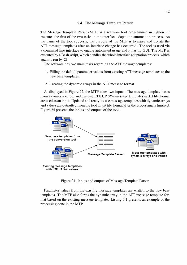
42
5.4. The Message Template Parser
The Message Template Parser (MTP) is a software tool programmed in Python. Itexecutes the first of the two tasks in the interface adaptation automation process. Asthe name of the tool suggests, the purpose of the MTP is to parse and update theATT message templates after an interface change has occurred. The tool is used viaa command line interface to enable automated usage and it has no GUI. The MTP isexecuted by a Bash script, which handles the whole interface adaptation process, whichagain is run by CI.The software has two main tasks regarding the ATT message templates:
1. Filling the default parameter values from existing ATT message templates to thenew base templates.
2. Creating the dynamic arrays in the ATT message format.
As displayed in Figure 22, the MTP takes two inputs. The message template basesfrom a conversion tool and existing LTE UP SWi message templates in .txt file formatare used as an input. Updated and ready-to-use message templates with dynamic arraysand values are outputted from the tool in .txt file format after the processing is finished.Figure 24 presents the inputs and outputs of the tool.
Figure 24: Inputs and outputs of Message Template Parser.
Parameter values from the existing message templates are written to the new basetemplates. The MTP also forms the dynamic array in the ATT message template for-mat based on the existing message template. Listing 5.1 presents an example of theprocessing done in the MTP.

43
Listing 5.1: Example of the base template processing done by Message TemplateParser
parameter1 (4) = 00000000parameter2 (1) = 00arrayCount (4) = 00000000arrayParameter1 (2) = 0000arrayParameter2 (2) = 0000parameter3 (4) = 00000000
(a) Before processing
parameter1 (4) = 0000AF3Cparameter2 (1) = AEarrayCount (4) = 00000001@dynamic(arrayName,arrayCount)
@arrayNamearrayParameter1 (2) = 0001arrayParameter2 (2) = FFFF
parameter3 (4) = 000000FE
(b) After processing
5.4.1. Process Description
The message templates from both inputs are read to memory. The MTP then comparesthe base message templates with the existing message templates of corresponding mes-sages one by one to find matching parameters. Two types of parameter matching areused. First, the parameters are matched straightforwardly by checking if the names andsizes of the parameters are equal. If not all parameters are matched in this comparison,the unmatched parameters are matched by using a comparison based on the Leven-shtein distance. Levenshtein distance is a metric, which can be used to determine thesimilarity between two strings. The similarity is calculated from the minimum amountof operations that is required to change one string into the other, an operation meaninga deletion, an insertion or a substitution of a single character. [36]
Once all parameters are matched, the MTP checks whether the existing template hasa dynamic array. If it has, the MTP maps the parameters belonging to the dynamicarray to the parameters in the base template. After the mapping is done, the ATTformatted dynamic array is created in the base template, replacing the correspondingparameters.
The ATT formatted dynamic arrays in the message templates have originally beencreated manually. They enable the usage of different amounts of opened dynamicarrays in the ATT using a single message template. However, the dynamic arraysare not required by the ATT by definition. For example, one could use a messagetemplate with nine opened dynamic arrays or a message template with an ATT messageformat dynamic array with nine as the value of the array count parameter. Albeit thefunctionality in these situations would be the same, the ATT dynamic array format issuperior as a single message template can be used in multiple situations and scenarios.After the initial manual creation of the ATT dynamic array format in the messagetemplate, it is always recreated by the MTP in the new base template when the MTPprocess is executed.

44
Statistics including the percentage of matched parameters and the results of dynamicarray processing for each base message template are then written to a log file. Onceall parameters are processed, the values from the existing templates are written to theparameters in the base templates. Finally, the newly formed message template files arecreated along with updating a few ATT specific configuration files. Figure 26 presentsthe MTP process in a UML activity diagram.Utilizing data from the existing templates means that the values stored in the files in
the SVN repository are always preserved and transferred to the new templates. Thisalso enables the team to have the ability to easily modify the values. As value changesare made and committed to the message template files in the SVN repository, theywill remain in the circulation as the MTP reads the values from the existing messagetemplates.
Figure 26: Activity diagram of the Message Template Parser process.

45
5.4.2. Challenges
The MTP process relies on the fact that all parameters can be matched between the twoinput templates. The matching is straightforward and simple, if the parameter namesare equal as every match is absolutely sure. This was not initially the case in LTE UPSWi, because not all of the message template parameter names were equal to the namesspecified in the IFS documents. Some parameter names were written using a slightlydifferent notation and some names were completely different. Parameter names in theATT message template format do not have a functional meaning in the actual eNodeBmessage, and they are used only as identifiers in the test scripts.
This problem was addressed by using the Levenshtein distance as a measuring met-ric for the similarity of two parameter names. Even after finding a good threshold forconfirming a match by trial and error, some parameter names could not be matchedautomatically. These parameter names were then matched by comparing their rela-tive position in the template. These matches were then verified by a manual check.After the first execution results were committed to the SVN repository, mismatchingparameter names removed and the parameter names made equal, the issue becamenonexistent. Listing 5.2 illustrates an example of this problem. Parameters in boldtext could be matched by equality, parameters in italic with Levenshtein distance andparameters in underlining with relative position.
Listing 5.2: Example of the mismatching parameter names
oneParameter (4) = 00000000secondParameter (1) = 00ueConfiguration (4) = 00000000cellParameter (2) = 0000
(a) Base template
oneParameter (4) = 0000AF3CscndParam (1) = AEbearerThreshold (4) = 00000001cellParameter (2) = 0001
(b) Existing template
A second problem was caused by a limitation in the ATT. The ATT message templateformat specifies that parameter size can be one, two or four bytes. However, the basetemplates from the conversion tool contained parameters also with sizes of three andeight bytes. This was solved by splitting these parameters into two parts. Parameterswith size of three bytes were split to two and one byte parameters and an eight byteparameter to two four byte parameters. Listing 5.3 illustrates the solution.
Listing 5.3: Example of the invalid parameter size problem
firstParameter (2) = 0000secondParameter (3) = 000000thirdParameter (8) = 0000000000000000
(a) Base template
firstParameter (2) = 0000secondParameter (2) = 0000secondParameter (1) = 00thirdParameter (4) = 00000000thirdParameter (4) = 00000000
(b) After MTP processing

46
5.5. The CSV Updater
The CSV Updater (CU) is a software tool programmed in Python. It handles the latterof the two tasks in the interface adaptation automation process. The purpose of thetool is to update the parameter value storage CSV files used in LTE UP SWi testingaccording to the changed specification. Like the MTP, the CU is operated via a com-mand line for automation purposes and it has no GUI. CU is executed by the same CIscript that runs the MTP and the whole interface adaptation automation process.The tool’s task is to modify the structure of the CSV files based on the occurred
interface change. The CU checks the changes from the newly updated ATT messagetemplates in .txt file format, which are used as an input to the tool. Existing CSVfiles from the SVN repository are used as another input for the comparison with theATT message templates. The CU outputs the updated CSV files after the processing isfinished. The inputs and outputs are displayed in Figure 29.
Figure 29: Inputs and outputs of CSV Updater.
The CU mirrors the structure of the message template in the corresponding CSVfile. If parameters are added to the message in an interface change, they are alsoadded to the CSV file with a zero value. The same process applies also to removedand renamed parameters. Listing 5.4 presents an example of the CU process. In thisexample scenario, one parameter is added to the message template UESetup. When theCU compares the message template with the existing CSV file, the difference is noticedand the CU adds the new parameter to the output CSV file. The added parameter isdisplayed in bold text.
5.5.1. Process Description
The CU reads both inputs, message templates and CSV files to memory in the begin-ning of the processing. All inputted CSV files are then processed. A correspondingmessage template is selected for each CSV file. The selection is done based on themessage name.

47
Listing 5.4: Example of the CSV updating process done by CSV Updater
oneParameter (4) = 00000000secondParameter (1) = 00ueConfiguration (4) = 00000000cellParameter (2) = 0000bearerSetup (1) = 00
(a) UESetup message template
UESetup_oneParameter,1,1,1UESetup_secondParameter,0,0,0UESetup_ueConfiguration,A,A,AUESetup_bearerSetup,0,0,0
(b) Existing CSV file
UESetup_oneParameter,1,1,1UESetup_secondParameter,0,0,0UESetup_ueConfiguration,A,A,AUESetup_cellParameter,0,0,0UESetup_bearerSetup,0,0,0
(c) Updated CSV file
After a template-CSV-pair is selected, it is then processed. First, the CU checkswhether the message template has a dynamic array. If one is detected, the CU writesthe dynamic array open 16 times. The amount of 16 times is selected based on the CSVfile structures, which contain the dynamic array parameter values for 16 different sets.By writing the dynamic array open 16 times in the message template, the comparisonof the parameter structures between the template and the CSV file is easy as everyparameter can be mapped uniquely.
The comparison between the message template and CSV file parameter structureis done next. Comparison is done by simply checking the equality of the parameternames. CSV parameters with the same name have a running index with an underscoreand an index number starting from the second same name parameter. These indexesare removed temporarily before the comparison to allow direct matching with the pa-rameters in the message templates, which do not contain indexing for parameters withthe same name.
If the CU finds that the structures of the template and CSV file differ, the changesare applied to the CSV file. New parameters in the template are added to the CSV fileand deleted parameters are deleted from the CSV file. Once the changes are made, theparameter counts are recalculated in the CSV file and the indexing is rewritten to theparameters with the same name. Finally, the CSV file data is written to a file. Figure 31presents the CU process in a UML activity diagram.
Similarly as the MTP, the CU utilizes the existing CSV files from the SVN repos-itory, meaning that the values stored in the CSV files are retained in the automationprocess. The values in the CSV files can be modified and committed back to the repos-itory freely and they will be included in the updated files processed by the CU in thefuture iterations.

48
Figure 31: Activity diagram of the CSV Updater process.
5.5.2. Challenges
Similar problems were faced in the implementation of the CU as with the MTP. Beforethis thesis implementation, the CSV file parameter names were not perfectly matchedto the parameter names described in the IFS documents. This led to problems whenmatching the newly created templates from the MTP to the existing CSV files in theSVN repository. This problem was solved by creating a JSON-formatted data struc-ture, which matched and paired these parameters by utilizing the Levenshtein distancemetric used in the MTP. A small script that uses this data structure was then written inPython to convert the parameter names in the CSV files to the parameter names defined

49
in the IFS. After this script was run one time and the results were checked manually,the CSV files were committed back to the SVN repository. This processing allowedthe CU to directly compare the equality of the parameter names without any deepercomparison. It also ensured that the CSV file structures were now fully aligned withthe message template structures.
The processing also led to a large refactoring and modification of the whole ATTtest script library to correct the parameter name references in the script commands.The refactoring was done by creating a parallel branch of the main branch in the SVNrepository and by creating a script, which modified the scripts automatically based onthe data structure created earlier. After the changes were made to the parallel branchand they were verified, the changes were merged back to the main branch.
5.6. The Scenario Configurator
The Scenario Configurator (SC) is a desktop application for creating and configuringtest scenarios and generating ATT test cases in the LTE UP SWi environment. Theapplication has a GUI for user-friendly usage as well as a command line interface forautomation support. Users can create test scenario files in the GUI, which containconfiguration and settings for a specific test case. These scenario files can be usedto automatically generate ATT test case scripts either via the GUI or the commandline interface. The test scripts can then be executed by the ATT as such, althoughmodifications and additions can be made manually afterwards.
The SC is designed to ease the process of creating a new test case script in the ATT.Due to the limited functionality of the ATT script syntax and complex parametrizationof the eNodeB, the creation of a new test case in the ATT is often a complicated taskand requires the tester to specify possibly hundreds of different parameters. The SCintroduces a new philosophy and practice for creating the test cases. Whereas the ATTutilizes blank message templates and applies parameter values to them in the variousscripts executed during a test case, the SC creates ready-made message templates,which contain all parameter values according to the test scenario specified by the user.These messages can then be sent to the eNodeB as such. Custom value settings canhowever be still applied to the messages in the generated ATT test case script.
The planning of the software was done by presenting the idea of the tool to the testingteam members and interviewing them afterwards to collect requirements. All ideas andrequirements that came up in the interviews were documented and then prioritized. Usecases were then derived from the prioritized requirements. The use cases were dividedinto two mandatory and optional categories.
The SC is programmed in Python and uses the Tkinter GUI package. The tool isdesigned to work in both Windows and Linux environments, which is achieved by thecross-platform functionality of Python and Tkinter. Figure 32 displays the main screenof the GUI in a Windows environment.

50
Figure 32: Screenshot of the Scenario Configurator GUI main screen running onWindows 7.
5.6.1. Requirements and Use Cases
The requirements for the software were devised from the necessities of the basic func-tionality and from the LTE UP SWi testing team personnel, who are the user groupof the software. Eight people were interviewed, one person at a time, for roughly 30minutes. All persons had been briefed of the idea of the software by email several daysbeforehand to allow familiarization and contemplation of the idea.
The interviews were conducted by using a brief slide show presentation. The pre-sentation summed up the core functionality of the planned software and highlightedthe difference in the way of working with the new software compared to the statusquo. After the quick induction from the presentation, the user was asked what featuresone would want to have in the software. Ideas that came up in the conversation weredocumented.
After the requirements were collected, they were prioritized by dividing them intothree categories. The first category consisted of requirements that were consideredessential for the software. The second category included requirements that could beimplemented if there were enough time, which would be good to have. The third andlast category had the requirements that could be excluded from the implementationimmediately for being too time-consuming, complex or too far out of the core scope

51
of the software, and could be considered as possible future improvements. Table 1displays the prioritized requirements for the SC.
Table 1: Prioritized requirements for Scenario Configurator
ID Requirement CategoryR-1 Ability to create a basic scenario as proof-of-concept Essential (1)R-2 Implementing two configurable basic LTE features Essential (1)R-3 Tool must be expandable to allow simple future development Essential (1)R-4 Ability to change a parameter value in a scenario Essential (1)R-5 Human-readable and standard scenario file format is needed Essential (1)R-6 Application must have standard parameter values in place by
defaultEssential (1)
R-7 Ability to use previous scenario as a template for a new sce-nario
Essential (1)
R-8 Support for adding and modifying LTE features to a scenario Essential (1)R-9 Cross-platform support for the application Essential (1)R-10 Ability for the user to select sent eNodeB messages and to
alter their orderEssential (1)
R-11 Including safeguards to prevent users of inputting erroneousparameter values
Essential (1)
R-12 Ability to configure a test scenario only partially with the tooland leave rest of the configuration to the ATT
Essential (1)
R-13 Having a field in the GUI to force parameter values to a mes-sage
Good to have (2)
R-14 Backwards compatibility of the scenario files Good to have (2)R-15 Ability to set boundary test values for parameters Good to have (2)R-16 Ability to compare two scenarios for differences Good to have (2)R-17 Ability to vary the timing of eNodeB message sending Future improve-
ments (3)R-18 Sending eNodeB messages straight to the BTS without using
the ATTFuture improve-ments (3)
These requirements were then converted to use cases. Similarly to the requirements,the use cases were divided into two categories. The first category includes the essentialuse cases and the second category consists of the optional use cases. Table 2 presentsthe use cases for the software.

52
Table 2: Use cases for Scenario Configurator
ID Use case CategoryUC-1 User can configure a basic capacity test scenario with varying
bandwidth, amount of users, transmission mode and throughputconfigurations
Essential (1)
UC-2 User can expand functionality of the application by adding newfeature information
Essential (1)
UC-3 User can override parameters in a scenario via command linearguments and/or JSON-formatted configuration file
Essential (1)
UC-4 User can edit scenario configuration files manually in a text ed-itor
Essential (1)
UC-5 User can select what messages will be sent in the test scenario,and alter their order
Essential (1)
UC-6 User can configure and run a test scenario only partially andleave some steps to ATT execution
Essential (1)
UC-7 User can forcefully set parameter values in the GUI Optional (2)UC-8 User can set a parameter boundary test scenario Optional (2)UC-9 User can compare two scenarios and see their differences Optional (2)UC-10 User can vary test cases by varying the timing of sent messages Optional (2)
Functionality for all essential use cases except UC-2 was implemented. During theimplementation process, the functionality for UC-2 was deemed too time-consumingand was not essential to reach the proof of concept state of the software. Functionalityfor the optional use cases were mostly not implemented in the software although userscan do functions described in UC-7 and UC-9 in the ATT test scripts generated by theSC.
5.6.2. The User Interface
The SC has both a graphical and a command line user interface. The GUI is the maininterface and it includes all of the functionality in the software. The command lineinterface is included to enable the generation of a test case from a test scenario file inthe ATT or manually.
The GUI is comprised of six sections and a log view. The sections contain config-uration options by which the user can set up the scenario. The menus accessible fromthe top of the window include file options, settings and the actions to generate the testcase. Figure 33 shows the different GUI sections.
The first section includes all of the available messages that can be added to the testscenario. Users can also define message blocks, which include multiple messages andcan be added to the scenario as one entry. Managing the message blocks is done viathe edit menu. The second section displays the selected messages in the test scenario.Message order can be rearranged and messages can be deleted via the provided buttonsor by using mouse gestures. The third section displays the message content when amessage is selected from the selected messages section. The fourth section contains

53
Figure 33: GUI sections of Scenario Configurator.
basic configuration settings for a test scenario. The user can configure the values forthe most common LTE features and, for example, the amount of UEs by interactingwith the GUI elements and inputting values to the fields. The fifth section is reservedfor the configuring of various LTE features in the scenario. The section is currentlyempty, because the use case UC-2 functionality has not been implemented at this time.The sixth section displays a summary of the scenario configuration in a text form. Thelog view displays log messages from the users’ actions in the GUI.
5.6.3. Process Description
The user creates the test scenarios in the GUI. The created test scenarios are savedin JSON-formatted files, which contain all configuration information for the scenario.New test scenarios can be created and existing ones loaded in the GUI. Listing 5.5displays an example of a scenario file content.

54
Listing 5.5: Example of a test scenario .json file1 {2 "name": "5mhz 1ue",3 "num_of_cells": 1,4 "trans_mode": "Open-loop dynamic MIMO",5 "rlc_mode": "AM mode",6 "ue_setup": "Random Access Procedure",7 "num_of_drbs": 1,8 "num_of_srbs": 1,9 "cells": {
10 "1": {11 "bandwidth": "5 MHz",12 "cell_mode": "A",13 "nondrx": 1,14 "drx": 0,15 "volte": 0,16 "nondata": 0,17 "sched": 1,18 "rrcconn": 1,19 "dl_tput": 30,20 "ul_tput": 2021 }22 },23 "messages": {24 "1": "LMGTT_ResetReq",25 "2": "Single cell setup",26 "3": "RACH user setup",27 "4": "User delete",28 "5": "Single cell delete"29 }30 }
First, the message template and CSV folder locations have to be defined in the set-tings. When the message template folder is set, the SC loads the available messagesto the first GUI section, listing the messages in a tree structure. The user then selectsand adds the wanted messages to the scenario and sets the configuration values in thebasic configuration section. The SC also offers an option to automatically select themessages to the scenario. The automatically selected messages are based on the user’sbasic configuration such as user setup method and the number of users and cells, whichhave an impact on the message selection. After everything is set, the user can save thescenario to a JSON-formatted file and generate the test case. Figure 34 presents a UMLactivity diagram of the usage of the software.
In the beginning of the generation process, the SC checks whether the scenario con-tains message blocks defined by the user. If it does, the message blocks are expandedinto individual messages. The SC then reads the needed message templates and theircorresponding CSV files into memory. The configuration of the scenario is then read

55
Figure 34: Activity diagram of the usage of Scenario Configurator.
from either the GUI elements or the scenario file, depending on whether the scenariois generated from the GUI or from the command line.Next, all messages are looped through in the order defined in the scenario. The SC
expands the possible dynamic arrays in the message templates by using an applicableconfiguration parameter from the user configuration. If no user defined configurationspecifies the dynamic array amount, the default value is read from the CSV file.Parameter values are applied to the message template first from the CSV file and then
from the user configuration. User configuration is applied last to overwrite the defaultvalue from the CSV file. CSV files provide default values for all message parametersand more specific user-defined parameters are applied over them to customize the testcase.Lastly, the message template is written to a file. Once the last message in the sce-
nario has been processed, the SC creates the needed ATT test scripts for the test case.Figure 35 presents the generation process in more detail in a UML activity diagram.This process is presented as the node “Generate the scenario” in Figure 34.

56
Figure 35: Activity diagram of the scenario generation process.
The test case can also be generated on-the-fly during an ATT test list execution. Thiscan be done by using the command line interface of the SC. The output directory andthe existing scenario file paths are given as the arguments to the tool. The generatedtest case can then be executed in the ATT immediately.The core idea of the ATT test execution is to go through all of the messages in the or-
der specified in the scenario and send them to the eNodeB without modifications as allof the needed parameters are written by the SC. This differs greatly from the traditionalway where all of the parameters are applied to the blank messages in ATT scripts. Also
57
the ATT test scripts can be executed as such, but they contain defined locations wherethe user can expand the functionality in the ATT. This functionality includes executingadditional ATT scripts at specific times in the test case sequence, setting parameters tothe request messages and reading values from the response messages.
5.6.4. Challenges
The implementation of the software turned out to be quite an extensive task. Withthe size of the software nearing 12 000 lines of code, bugs were sometimes difficult topinpoint and find even considering the usage of the TDD method. The developmentof the GUI was done first and it was rather slow due to limited experience in GUIprogramming and Tkinter. Many of the classes and code sections could be reusedwith minor changes from the other tools created during this thesis, which helped a lottimewise. All in all, no major obstacles were encountered during the implementationof the SC.

58
6. RESULTS AND DISCUSSION
The work presented in this thesis is intended to increase the level of automation ineNodeB software integration testing. Two separate improvements are introduced, bothaimed to solve or alleviate a certain problem in the LTE UP SWi area. The interfaceadaptation automation tools were developed to remove manual work from the processthus shortening the CI feedback cycle length and reducing the amount of errors gener-ated. The Scenario Configurator was developed as an alternative way of creating testcases, aiming to make test case scripting easier and less complex. This chapter presentsthe results and findings of the work produced in this thesis.
6.1. Implementation Status
The implementation of the software consisted of two distinct entities: interface adap-tation automation tools (MTP and CU) and the test scenario configuration tool (SC).In its current state, the MTP fulfills its requirements completely. No known softwarebugs exist at the time of writing. 1343 lines of code were written for the software,including the testing code. The unit test suite of the software consists of 42 test cases,which all pass. A code coverage check for the unit tests indicates a 91 percent linecoverage of the production code. No future improvement possibilities are stated at thetime of writing.
The implementation of the CU is finished and no bugs are known to exist at the timeof writing. 1364 lines of code were written for the software, including the testing code.The unit test suite of the software consists of 30 test cases, which are all passed. A codecoverage check for the unit tests indicates a 93 percent line coverage of the productioncode.
The implementation of the SC in its current state fulfills most of the essential re-quirements set in the planning phase of the project. The software can be used to createfully working test cases from the test scenario configuration. This meets the main re-quirement that the tool can be used to create a proof of concept basic test scenario todemonstrate the new philosophy for creating test cases. Several test cases generatedby the SC were executed in regression on a LTE UP SWi test line to verify the correctfunctionality. 11 602 lines of code were written for the software, including the test-ing code. The unit test suite of the software consists of 102 test cases, which are allpassed. A code coverage check for the unit tests indicates a 93 percent line coverageof the production code.
6.2. Findings and Impact
The automated interface adaptation tools have been in use since October 2014. Sincethat time there have been 108 changes in the interface specification that have had aneffect on LTE UP SWi test scripts and files. All of these interface changes have beencorrectly processed by the developed automation tools with no manual interventionsneeded. The average processing time for the automation process has been observed tobe roughly 10 minutes. Before the automated process, the interface adaptation work

59
was done manually and could consume the work effort of multiple people for manydays, during which the normal testing process was halted as new software builds couldnot be tested. The manual work often even left bugs in the test scripts and messagetemplates, which were hard to find and pinpoint. The bugs often meant that some con-trol messages sent to the eNodeB were still aligned to the old interface specification orwere otherwise misformed. Sending erroneous messages caused unexpected behaviorwith miscellaneous symptoms and often it was not evident what the source of the errorswas.
Compared to the previous way of working, the automated process is a significantimprovement. Manual involvement is no longer needed, adaptation is done quicklyand automated tools remove the risk of human errors. No erroneous output files weredetected after any interface change and no tests encountered problems that could beexplained by test script or message template errors caused by the interface adaptationsystem. The automated process allows the testers to concentrate on more valuabletasks and testing of the latest software builds is never interrupted due to interface mis-alignment. The automation tools meet their requirements as the feedback cycle in CItesting is now significantly shorter than before in the case of an interface change.
The idea behind the development of the SC was to create a proof of concept softwarefor an alternative way of creating test cases in the LTE UP SWi environment, whichwould require less complex test script writing and manual parameter setting than be-fore. This was achieved by creating a GUI in which the tester could select the desiredfeatures and settings for a specific test case and then generate the ATT test script fromthe users’ selections. In the end it was possible to create basic test scenarios, generatethe test case scripts and run them either manually or in CI with a minimal amount ofmanual test case writing. Now, a tester would set up a test scenario in the SC anda small ATT test script, which would initialize the test parameters in the ATT envi-ronment and generate eNodeB control messages in the SC. The SC was successfullytested in periodic CI testing during the end of the development with several differenttest case options. It was proven that it is possible to use pregenerated ATT test scriptsand eNodeB control messages in LTE UP SWi testing. As the proof of concept stateof the software was achieved, the work fulfills its requirements.
6.3. Limitations
There are a few limitations regarding the interface adaptation automation tools. Itwas observed that if the LTE UP SWi SVN repository is unresponsive or very slow, theautomation process might exit prematurely and the adaptation would be left unfinished.In such a case the only solution is to restart the automation process manually. Anotherlimitation concerns situations where the new interface specification is not yet used inthe latest eNodeB software builds. However, the automation process commits filesadapted to the newest interface specifications immediately, regardless of the revisionused in the software builds. This means that testers have to wait until the newestinterface specification is used in the software build before updating the interface fileson the test lines’ working copies.
SC functionality demonstrated that it is possible to set up LTE UP SWi test cases byautomatically generating the scripts and eNodeB control messages from the settings

60
selected by the user. In the current state, the functionality is limited to a very basicset of configurable features in the test case. More extensive test cases still have to becreated manually using ATT scripting. The GUI approach in its current state does notallow test case customization beyond the presented settings, which is often necessary.However, test cases can still be customized by editing the generated ATT test scriptsmanually. Furthermore, programming all possible variations and functionalities to theSC would be very laborious and keeping the test case generation in the SC up-to-datewith all changes in the eNodeB software would require lots of work.
6.4. Future Work
Many features and functionalities in the SC were discussed and pondered, which werenot included in the implementation in the thesis scope as the main goal was to make aproof of concept tool for a new way of working. The most important functionality thatwas left out from the implementation is the capability to set, configure and add LTEfeatures to the tool and to the scenarios. The idea is that the user could select desiredfeatures to be either enabled or disabled in a scenario and configure the parametersconnected to that feature. This functionality was described in the requirements R-3and R-8 and the use case UC-2. The most common features that were necessary toimplement to make the basic test case were implemented and the configuration can bedone in the basic configuration section of the GUI.
More features can be added by implementing the functionalities described in theoptional use cases, and good-to-have and future improvement requirements. The SCcould replace the ATT completely by implementing the ability to send and receiveeNodeB messages straight from the tool itself without resorting to the ATT scripts.This feature would require an extensive amount of work, but the tool would be lesscustom built for the LTE UP SWi environment and, as a stand alone software, wouldpossibly enable wider use of the tool.

61
7. SUMMARY
The objective of this thesis work was to improve LTE eNodeB User Plane (UP) soft-ware integration (SWi) testing by increasing the level of automation in the continuousintegration (CI) environment. Automating manual work processes reduces the amountof human mistakes, shortens the CI feedback cycle delay and allows people to do morehigher-value work. Fast and automated testing is essential in agile software develop-ment and CI environment as software is developed in small increments and new buildsare created frequently.
Two different issues in the test automation were addressed; interface specificationadaptation and test case configuration. A system of two programs, Message TemplateParser and CSV Updater, was implemented to automate the interface specificationadaptation. For automatic test case configuration, Scenario Configurator, a softwaretool with a graphical user interface, was developed.
Interface adaptation in LTE UP SWi testing requires keeping the eNodeB controlmessages and the environment configuration updated to the latest interface specifica-tion. The Message Template Parser modifies and updates the control message tem-plates and the CSV Updater updates the test environment parameters in existing CSVfiles. The system is triggered automatically in the CI environment whenever an inter-face specification change occurs.
The Scenario Configurator introduces an alternative way to create test cases in theLTE UP SWi environment. The software allows testers to configure test case scenariosand messaging sequences in a graphical user interface. Test case scripts with corre-sponding parameters can then be generated automatically by the program from thescenario.
The interface specification automation system has been in use for over a year and ithas handled over 100 interface changes. The system has worked as intended and allinterface changes have been correctly processed with an average execution time of 10minutes. This is a significant reduction as manual process often took many hours oreven days to complete. In addition, no errors have been observed in the resulting filesand parameters.
The Scenario Configurator meets its target as a proof of concept software for analternative approach for creating test cases. At the end of the development during thethesis work, the software reached a point where basic test cases could be configuredand generated and the test scripts could be executed correctly. However, further devel-opment is still needed to allow more detailed configuration of the test scenarios.
62
8. REFERENCES
[1] Dahlman E., Parkvall S. & Skold J. (2013) 4G: LTE/LTE-Advanced for MobileBroadband. Elsevier Science.
[2] Johnson C. (2010) Long Term Evolution IN BULLETS. John Wiley & Sons, Inc,1st ed.
[3] Holma H. & Toskala A. (2009) LTE for UMTS - OFDMA and SC-FDMA BasedRadio Access. John Wiley & Sons, Ltd.
[4] 3GPP specification 25.913 - Requirements for Evolved UTRA (E-UTRA)and Evolved UTRAN (E-UTRAN). URL: http://www.3gpp.org/DynaReport/25913.htm, Online; accessed 6-January-2015.
[5] Abdullah M., Jiwa Abdullah A., Ghanim M. & Malaysia H.O. (2011) Com-parison Study on 3.9 G and 4G Evolution. Information Communication andManagement–International Proceedings of Computer Science and InformationTechnology .
[6] Wannstrom J., LTE-Advanced. URL: http://www.3gpp.org/technologies/keywords-acronyms/97-lte-advanced, Online;accessed 5-January-2015.
[7] UMTS Forum Report 44 - Mobile traffic forecasts 2010-2020 report.URL: http://www.umts-forum.org/component/option,com_docman/task,doc_download/gid,2537/Itemid,213/, Online;accessed 5-January-2015.
[8] Patel S., Chauhan M. & Kapadiya K. (2012) 5G: Future Mobile Technology-Vision 2020. International Journal of Computer Applications 54.
[9] Firmin F., The Evolved Packet Core. URL: http://www.3gpp.org/technologies/keywords-acronyms/100-the-evolved-packet-core, Online; accessed 6-January-2015.
[10] 3GPP specification 36.300 - Evolved Universal Terrestrial Radio Access(E-UTRA) and Evolved Universal Terrestrial Radio Access Network (E-UTRAN); Overall description; Stage 2. URL: http://www.3gpp.org/DynaReport/36300.htm, Online; accessed 6-January-2015.
[11] Highsmith J. & Cockburn A. (2001) Agile software development: the business ofinnovation. Computer 34, pp. 120–127.
[12] Schwaber K. (1995) Scrum development process. In: Proceedings of the 10thAnnual ACM Conference on Object Oriented Programming Systems, Languages,and Applications (OOPSLA), pp. 117–134.
[13] Pressman R. (2010) Software Engineering: A Practitioner’s Approach. McGraw-Hill, Inc., New York, NY, USA, 7 ed.

63
[14] Martin R.C. (2003) Agile Software Development: Principles, Patterns, and Prac-tices. Prentice Hall PTR, Upper Saddle River, NJ, USA.
[15] Beck K., Beedle M., van Bennekum A., Cockburn A., Cunningham W., FowlerM., Grenning J., Highsmith J., Hunt A., Jeffries R., Kern J., Marick B., MartinR.C., Mellor S., Schwaber K., Sutherland J. & Thomas D. (2001), Manifestofor Agile Software Development. URL: http://www.agilemanifesto.org/, Online; accessed 25-February-2015.
[16] Jacobson I. (2002) A Resounding ‘Yes’ to Agile Processes-But Also to More.Cutter IT Journal 15, pp. 18–24.
[17] Schwaber K. (2004) Agile Project Management With Scrum. Microsoft Press,Redmond, WA, USA.
[18] Janzen D. & Saiedian H. (2005) Test-Driven Development: Concepts, Taxonomy,and Future Direction. Computer 38, pp. 43–50.
[19] Janzen D. & Saiedian H. (2008) Does Test-Driven Development Really ImproveSoftware Design Quality? Software, IEEE 25, pp. 77–84.
[20] Duvall P., Matyas S. & Glover A. (2007) Continuous Integration: ImprovingSoftware Quality and Reducing Risk. Addison-Wesley Professional, first ed.
[21] Fowler M., Continuous Integration. URL: http://www.martinfowler.com/articles/continuousIntegration.html, Online; accessed 4-March-2015.
[22] Karlesky M., Williams G., Bereza W. & Fletcher M. (2007) Mocking the Em-bedded World: Test-Driven Development, Continuous Integration, and DesignPatterns. In: Proc. Emb. Systems Conf, CA, USA, pp. 1518–1532.
[23] Stolberg S. (2009) Enabling Agile Testing through Continuous Integration. In:Agile Conference, 2009. AGILE ’09., pp. 369–374.
[24] McConnell S. (1996) Daily Build and Smoke Test. IEEE Software 13, pp.144,143.
[25] Myers G.J. & Sandler C. (2004) The Art of Software Testing. John Wiley & Sons,second ed.
[26] Galin D. (2004) Software Quality Assurance: From Theory to Implementation.Pearson/Addison Wesley.
[27] Ammann P. & Offutt J. (2008) Introduction to Software Testing. Cambridge Uni-versity Press, New York, NY, USA, 1 ed.
[28] Baresi L. & Pezzè M. (2006) An Introduction to Software Testing. Electron.Notes Theor. Comput. Sci. 148, pp. 89–111.
[29] The Python Tutorial — Python 2.7.9 documentation. URL: https://docs.python.org/2.7/tutorial/, Online; accessed 16-March-2015.

64
[30] BeginnersGuide/Overview - Python Wiki. URL: https://wiki.python.org/moin/BeginnersGuide/Overview, Online; accessed 16-March-2015.
[31] TkInter - Python Wiki. URL: https://wiki.python.org/moin/TkInter, Online; accessed 16-March-2015.
[32] PyCharm Python/Django IDE Features. URL: https://www.jetbrains.com/pycharm/features/, Online; accessed 23-March-2015.
[33] Newham C. (2005) Learning the bash Shell: Unix Shell Programming. In a Nut-shell (O’Reilly), O’Reilly Media.
[34] What Is Subversion? URL: http://svnbook.red-bean.com/en/1.7/svn.intro.whatis.html, Online; accessed 16-March-2015.
[35] Meet Jenkins - Jenkins - Jenkins Wiki. URL: https://wiki.jenkins-ci.org/display/JENKINS/Meet+Jenkins, Online; accessed 18-March-2015.
[36] Su Z., Ahn B.R., Eom K.Y., Kang M.K., Kim J.P. & Kim M.K. (2008) PlagiarismDetection Using the Levenshtein Distance and Smith-Waterman Algorithm. In:Innovative Computing Information and Control, 2008. ICICIC ’08. 3rd Interna-tional Conference on, p. 569.