ts 102 606-1 - v1.2.1 - digital video broadcasting … · etsi 6 etsi ts 102 606-1 v1.2.1 (2014-07)...
TRANSCRIPT
ETSI TS 102 606-1 V1.2.1 (2014-07)
Digital Video Broadcasting (DVB); Generic Stream Encapsulation (GSE);
Part 1: Protocol
TECHNICAL SPECIFICATION

ETSI
ETSI TS 102 606-1 V1.2.1 (2014-07)2
Reference RTS/JTC-DVB-338-1
Keywords broadcasting, DVB
ETSI
650 Route des Lucioles F-06921 Sophia Antipolis Cedex - FRANCE
Tel.: +33 4 92 94 42 00 Fax: +33 4 93 65 47 16
Siret N° 348 623 562 00017 - NAF 742 C
Association à but non lucratif enregistrée à la Sous-Préfecture de Grasse (06) N° 7803/88
Important notice
The present document can be downloaded from: http://www.etsi.org
The present document may be made available in electronic versions and/or in print. The content of any electronic and/or print versions of the present document shall not be modified without the prior written authorization of ETSI. In case of any
existing or perceived difference in contents between such versions and/or in print, the only prevailing document is the print of the Portable Document Format (PDF) version kept on a specific network drive within ETSI Secretariat.
Users of the present document should be aware that the document may be subject to revision or change of status. Information on the current status of this and other ETSI documents is available at
http://portal.etsi.org/tb/status/status.asp
If you find errors in the present document, please send your comment to one of the following services: http://portal.etsi.org/chaircor/ETSI_support.asp
Copyright Notification
No part may be reproduced or utilized in any form or by any means, electronic or mechanical, including photocopying and microfilm except as authorized by written permission of ETSI.
The content of the PDF version shall not be modified without the written authorization of ETSI. The copyright and the foregoing restriction extend to reproduction in all media.
© European Telecommunications Standards Institute 2014.
© European Broadcasting Union 2014. All rights reserved.
DECTTM, PLUGTESTSTM, UMTSTM and the ETSI logo are Trade Marks of ETSI registered for the benefit of its Members.
3GPPTM and LTE™ are Trade Marks of ETSI registered for the benefit of its Members and of the 3GPP Organizational Partners.
GSM® and the GSM logo are Trade Marks registered and owned by the GSM Association.

ETSI
ETSI TS 102 606-1 V1.2.1 (2014-07)3
Contents
Intellectual Property Rights ................................................................................................................................ 5
Foreword ............................................................................................................................................................. 5
Modal verbs terminology .................................................................................................................................... 5
Introduction ........................................................................................................................................................ 6
1 Scope ........................................................................................................................................................ 7
2 References ................................................................................................................................................ 7
2.1 Normative references ......................................................................................................................................... 7
2.2 Informative references ........................................................................................................................................ 8
3 Definitions and abbreviations ................................................................................................................... 8
3.1 Definitions .......................................................................................................................................................... 8
3.1 Abbreviations ..................................................................................................................................................... 8
4 Generic Stream Encapsulation (GSE) Protocol ........................................................................................ 9
4.1 GSE Principles ................................................................................................................................................... 9
4.1.1 Fragmentation and Reassembly .................................................................................................................. 10
4.1.2 Network Protocol Identification ................................................................................................................. 11
4.1.3 Addressing and Hardware Filtering ............................................................................................................ 11
4.1.4 Locating GSE Streams ................................................................................................................................ 11
4.1.5 Transporting Signalling Information .......................................................................................................... 11
4.2 GSE Packet Format .......................................................................................................................................... 12
4.2.1 Specification ............................................................................................................................................... 12
4.2.2 CRC-32 Trailer ........................................................................................................................................... 15
4.2.3 GSE Packet Types ...................................................................................................................................... 16
4.2.4 Data Field Format ....................................................................................................................................... 16
4.3 Fragmentation ................................................................................................................................................... 17
4.3.1 Rules of operation ....................................................................................................................................... 17
4.3.2 Process description ..................................................................................................................................... 18
5 Labels: Addresses and Binding .............................................................................................................. 19
6 GSE SI specifications ............................................................................................................................. 20
Annex A (normative): Receiver Processing ....................................................................................... 21
A.1 Filtering .................................................................................................................................................. 21
A.2 Reassembly ............................................................................................................................................. 21
A.3 Protocol Type and Next Header Processing ........................................................................................... 22
A.4 Label re-use ............................................................................................................................................ 22
A.5 Padding ................................................................................................................................................... 22
A.6 Hypothetical Receiver Buffer Model ..................................................................................................... 22
A.6.1 Physical layer pipe buffer ................................................................................................................................. 23
A.6.2 GSE de-capsulation buffer ............................................................................................................................... 23
A.6.3 Header decompression module ......................................................................................................................... 23
A.6.4 RTP de-capsulation buffer ................................................................................................................................ 24
A.6.5 Re-multiplexing buffer ..................................................................................................................................... 24
A.6.6 Media decoding module ................................................................................................................................... 24
A.6.7 Decoded data buffer ......................................................................................................................................... 25
A.6.8 Signalling and Requirements for Hypothetical Receiver Buffer Model Parameters ........................................ 25
A.6.8.1 RTP de-capsulation buffer buffering time .................................................................................................. 25
A.6.8.2 Minimal RTP de-capsulation buffer size .................................................................................................... 25
A.6.8.3 Initial decoded data buffer time .................................................................................................................. 26
A.6.8.4 Service alternative grouping ....................................................................................................................... 26
ETSI
ETSI TS 102 606-1 V1.2.1 (2014-07)4
A.6.8.5 Decoding dependency grouping ................................................................................................................. 26
A.6.8.6 Service components synchronization grouping .......................................................................................... 26
A.6.9 Example ............................................................................................................................................................ 27
Annex B (informative): Encapsulator Processing ............................................................................... 28
B.1 Encapsulator/Scheduler Functions ......................................................................................................... 28
B.2 Use of the Label Type Indicator ............................................................................................................. 30
Annex C (informative): GSE Packet Format Examples ..................................................................... 31
Annex D (normative): GSE-Lite Profile ............................................................................................. 33
D.1 Overview ................................................................................................................................................ 33
D.2 GSE-Lite Profile Restrictions ................................................................................................................. 33
D.2.1 PDU size ........................................................................................................................................................... 34
D.2.2 Fragmentation ................................................................................................................................................... 34
Annex E (informative): Bibliography ................................................................................................... 35
History .............................................................................................................................................................. 36

ETSI
ETSI TS 102 606-1 V1.2.1 (2014-07)5
Intellectual Property Rights IPRs essential or potentially essential to the present document may have been declared to ETSI. The information pertaining to these essential IPRs, if any, is publicly available for ETSI members and non-members, and can be found in ETSI SR 000 314: "Intellectual Property Rights (IPRs); Essential, or potentially Essential, IPRs notified to ETSI in respect of ETSI standards", which is available from the ETSI Secretariat. Latest updates are available on the ETSI Web server (http://ipr.etsi.org).
Pursuant to the ETSI IPR Policy, no investigation, including IPR searches, has been carried out by ETSI. No guarantee can be given as to the existence of other IPRs not referenced in ETSI SR 000 314 (or the updates on the ETSI Web server) which are, or may be, or may become, essential to the present document.
Foreword This Technical Specification (TS) has been produced by Joint Technical Committee (JTC) Broadcast of the European Broadcasting Union (EBU), Comité Européen de Normalisation ELECtrotechnique (CENELEC) and the European Telecommunications Standards Institute (ETSI).
NOTE: The EBU/ETSI JTC Broadcast was established in 1990 to co-ordinate the drafting of standards in the specific field of broadcasting and related fields. Since 1995 the JTC Broadcast became a tripartite body by including in the Memorandum of Understanding also CENELEC, which is responsible for the standardization of radio and television receivers. The EBU is a professional association of broadcasting organizations whose work includes the co-ordination of its members' activities in the technical, legal, programme-making and programme-exchange domains. The EBU has active members in about 60 countries in the European broadcasting area; its headquarters is in Geneva.
European Broadcasting Union CH-1218 GRAND SACONNEX (Geneva) Switzerland Tel: +41 22 717 21 11 Fax: +41 22 717 24 81
Founded in September 1993, the DVB Project is a market-led consortium of public and private sector organizations in the television industry. Its aim is to establish the framework for the introduction of MPEG-2 based digital television services. Now comprising over 200 organizations from more than 25 countries around the world, DVB fosters market-led systems, which meet the real needs, and economic circumstances, of the consumer electronics and the broadcast industry.
The present document is part 1 of a multi-part deliverable covering the Generic Stream Encapsulation (GSE), as identified below:
Part 1: "Protocol";
Part 2: "Logical Link Control (LLC)";
Part 3: "Robust Header Compression (ROHC) for IP".
Modal verbs terminology In the present document "shall", "shall not", "should", "should not", "may", "may not", "need", "need not", "will", "will not", "can" and "cannot" are to be interpreted as described in clause 3.2 of the ETSI Drafting Rules (Verbal forms for the expression of provisions).
"must" and "must not" are NOT allowed in ETSI deliverables except when used in direct citation.

ETSI
ETSI TS 102 606-1 V1.2.1 (2014-07)6
Introduction The present document includes the definition of the Generic Stream Encapsulation (GSE) protocol, which allows for efficient encapsulation of IP and other network layer packets over a "generic" physical layer. Such a "generic" physical layer is intended as a transport mode that carries a sequence of data bits or data packets, possibly organized in frames, but with no specific timing constraints.
The first generation of DVB standards only supported data transport using the MPEG format (see ISO/IEC 13818-1 [4]), with a Transport Stream packet multiplex (MPEG-TS). Multi Protocol Encapsulation (EN 301 192 [3]) is the DVB standard for encapsulation of audio/video and other content on MPEG-TS packets. The second generation of DVB standards features backwards compatibility modes for carrying MPEG-TS as well as generic modes for carrying arbitrary packets of variable length. These are referred to as Generic Streams (GS).
The GSE protocol has been devised as an adaptation layer to provide network layer packet encapsulation and fragmentation functions over Generic Stream. GSE provides efficient encapsulation of IP datagrams over variable length Layer 2 packets, which are then directly scheduled on the physical layer into Base Band frames.
GSE maximizes efficiency of IP datagrams transport reducing overhead by a factor 2 to 3 with respect to MPE over MPEG-TS. This is achieved without any compromise of the functionalities provided by the protocol, due to the variable length Layer 2 packet size, suited to IP traffic characteristics. For example in an interactive DVB-S2 system, the overhead is reduced on average from about 10 % for MPE/MPEG-TS to 2 % to 3 % for GSE. Hence yielding an overall throughput gain of about 5 % to 15 %, the actual benefit is of course dependent on the concrete system and traffic characteristics.
In addition to the overhead reduction, GSE provides a more efficient system operation for interactive systems that utilize advanced physical layer techniques such as for instance Adaptive Coding and Modulation (ACM). The inherent channel rate variability experienced in ACM systems makes the Generic Stream format more suited than the Transport Stream. GSE provides a flexible fragmentation and encapsulation method, which permits use of a smart scheduler to optimize system performance, either by increasing the total throughput and/or by improving the average packet end-to-end delay. In addition, GSE flexibility leads to a reduction in packet loss under fading variations, allowing the scheduler at the transmitter to dynamically change transmission parameters (for example modulation format, coding rate) for a particular network layer packet.
GSE also provides additional features that increase the protocol flexibility and applicability. Some key GSE functions/characteristics are:
• Support for multi-protocol encapsulation (IPv4, IPv6, MPEG, ATM, Ethernet, 802.1pQ VLANs, etc.).
• Transparency to network layer functions, including IP encryption and IP header compression.
• Support of several addressing modes: In addition to the 6-byte MAC address (including multicast and unicast), it supports a MAC addressless mode, and an optional 3-byte address mode.
• A mechanism for fragmenting IP datagrams or other network layer packets over Base Band frames to support ACM/VCM.
• Support for hardware filtering.
• Extensibility: additional link protocols can be included through specific protocol type values (e.g. Layer 2 security, IP Header Compression, etc.).
• Low complexity.

ETSI
ETSI TS 102 606-1 V1.2.1 (2014-07)7
1 Scope The present document specifies the Generic Stream Encapsulation (GSE) protocol.
2 References References are either specific (identified by date of publication and/or edition number or version number) or non-specific. For specific references, only the cited version applies. For non-specific references, the latest version of the referenced document (including any amendments) applies.
Referenced documents which are not found to be publicly available in the expected location might be found at http://docbox.etsi.org/Reference.
NOTE: While any hyperlinks included in this clause were valid at the time of publication, ETSI cannot guarantee their long term validity.
2.1 Normative references The following referenced documents are necessary for the application of the present document.
[1] ETSI EN 302 307: "Digital Video Broadcasting (DVB); Second generation framing structure, channel coding and modulation systems for Broadcasting, Interactive Services, News Gathering and other broadband satellite applications (DVB-S2)".
[2] ETSI EN 302 755: "Digital Video Broadcasting (DVB); Frame structure channel coding and modulation for a second generation digital terrestrial television broadcasting system (DVB-T2)".
[3] ETSI EN 301 192: "Digital Video Broadcasting (DVB); DVB specification for data broadcasting".
[4] ISO/IEC 13818-1: "Information technology -- Generic coding of moving pictures and associated audio information: Systems".
[5] IETF RFC 4326: "Unidirectional Lightweight Encapsulation (ULE) for Transmission of IP Datagrams over an MPEG-2 Transport Stream (TS)".
[6] IETF RFC 3819: "Advice for Internet Subnetwork Designers".
[7] IETF RFC 1112: "Host extensions for IP multicasting".
[8] IETF RFC 2464: "Transmission of IPv6 Packets over Ethernet Networks".
[9] IETF RFC 5163: "Extension Formats for Unidirectional Lightweight Encapsulation (ULE) and the Generic Stream Encapsulation (GSE)".
[10] IETF RFC 3095: "RObust Header Compression (ROHC): Framework and four profiles: RTP, UDP, ESP, and uncompressed".
[11] IETF RFC 5888: "The Session Description Protocol (SDP) Grouping Framework".
[12] IETF RFC 5583: "Signaling Media Decoding Dependency in the Session Description Protocol (SDP)".
[13] IETF RFC 4566: "SDP: Session Description Protocol".
ETSI
ETSI TS 102 606-1 V1.2.1 (2014-07)8
2.2 Informative references The following referenced documents are not necessary for the application of the present document but they assist the user with regard to a particular subject area.
[i.1] Void.
[i.2] ETSI TS 102 606-3: "Digital Video Broadcasting (DVB); Generic Stream Encapsulation (GSE); Part 3: Robust Header Compression (ROHC) for IP".
3 Definitions and abbreviations
3.1 Definitions For the purposes of the present document, the following terms and definitions apply:
fragmentation: splitting PDU and Extension Header data over two or more GSE Packets
slicing: splitting a GSE packet over two or more contiguous physical layer frames
3.1 Abbreviations For the purposes of the present document, the following abbreviations apply:
ABNF Augmented Backus–Naur Form ACM Adaptive Coding and Modulation ADU Application Data Unit AM Adapter Module ATM Asynchronous Transfer Mode BB Base Band CRC Cyclic Redundancy Check DDB Decoded Data Buffer DVB Digital Video Broadcast E End indicator EBU European Broadcasting Union GDB GSE De-capsulation Buffer GS Generic Stream GSE Generic Stream Encapsulation HDM Header Decompression Module HEM High Efficiency Mode HRBM Hypothetical Receiver Buffer Model IANA Internet Assigned Numbers Authority IEEE Institute of Electrical and Electronics Engineers IETF Internet Engineering Task Force IP Internet Protocol IPR Intellectual Property Rights IR Initialization and Refresh IR-DYN IR Dynamic (i.e. without static information) ISO International Standard Organization JTC Joint Technical Committee LLC Logical Link Control LT Label Type indicator MAC Medium Access Control MB Megabytes MDM Media Decoding Module MODCOD MODulation and CODing MPE Multi Protocol Encapsulation MPEG Moving Pictures Experts Group

ETSI
ETSI TS 102 606-1 V1.2.1 (2014-07)9
MPLS Multiple Protocol Label Switching MTU Maximum Transmission Unit NPA Network Point of Attachment PDU Protocol Data Unit PLP Physical Layer Pipe PLPB Physical Layer Pipe Buffer PVC Permanent Virtual Circuit QoS Quality of Service RCS Return Channel System RDM ROHC Decoding Module RFC Request For Comment (IETF standard) RMB Re-Multiplexing Buffer ROHC RObust Header Compression RTCP RTP Control Protocol RTP Real-time Transport Protocol RTPDB RTP De-capsulation Buffer S Start indicator SA Service Alternative SDP Session Description Protocol SI Service Information SVC Scalable Video Coding TS Transport Stream UDP User Datagram Protocol ULE Unidirectional Lightweight Encapsulation VCI Virtual Channel Identifier VCM Variable Coding and Modulation VLAN Virtual LAN VPI Virtual Path Identifier
4 Generic Stream Encapsulation (GSE) Protocol
4.1 GSE Principles Figure 1 illustrates GSE operation. IP datagrams, Ethernet Frames, or other network layer packets, herein named Protocol Data Units (PDUs), that are scheduled for transmission, are encapsulated in one or more GSE Packets. The encapsulation process delineates the start and end of each network-layer PDU, adds control information such as the network protocol type and address label, and provides an overall integrity check when needed.
The PDU may be encapsulated in a single GSE Packet or sliced into PDU fragments and encapsulated in several GSE Packets. GSE Packets have in general variable length, in order to match the input IP traffic with minimum overhead.
GSE Packets may be sent in different Base Band frames, not necessarily consecutive or with the same transmission parameters (modulation format, coding rate). Moreover, no constraint on the GSE Packet position within the frame is assumed. However, GSE Packets shall not be reordered between encapsulator and de-encapsulator. In general, a Base Band frame may multiplex more than a single GSE Packet. Base Band frames may have fixed or variable length.
GSE does not include a mechanism for integrity check of single GSE Packets. A CRC-32 is only appended to the last PDU fragment of a fragmented PDU to verify the correctness of the reassembly operation. GSE relies on the physical layer being able to ensure the required error detection and/or correction probability (see RFC 3819 [6] for best current practices in IP networks). The present approach is independent of the specific physical layer provided that this meets the required level for error detection capability.

ETSI
ETSI TS 102 606-1 V1.2.1 (2014-07)10
Figure 1: GSE encapsulation within DVB protocol stack
In a system where ACM is utilized, transmission parameters typically change dynamically on a frame-by-frame basis. A receiver will generally successfully decode only a subset of the transmitted frames, i.e. only the ones whose transmission parameters are compatible with the receiver's current channel conditions.
Physical layers shall deliver GSE packets transparently as they were delivered to the physical layer on the transmission side. Physical layers may perform slicing of GSE packets, if the GSE packets are reassembled by the physical layer before any frames containing GSE packets are delivered to the GSE layer. All frames containing GSE packets which are exchanged between the GSE layer and physical layers shall start with the GSE header of the first GSE packet.
NOTE: Figure 1 shows fragmentation of network PDUs into GSE Packets. The GSE Packets are inserted into Base Band frames without slicing in figure 1.
GSE Packets, including fragments of the same encapsulated PDU, can be scheduled without any restriction (on the frame transmission parameter, on the frame position within the sequence of frames or on the GSE Packet position within the frame) in the Base Band frames. Transmission of fragments shall be in-sequence, preserving the transmit order. The GSE reassembly mechanisms support reconstructing the original PDU regardless of the position of GSE Packets in the transmitted frames.
Optimal efficiency of GSE over a physical layer with ACM requires the encapsulator/scheduler to have a-priori knowledge of the Base Band frame lengths (either fixed or variable). Then utilization of the DataField of a Base Band Frame can be optimized through fragmentation. GSE can fragment PDUs into fragments of arbitrary size. Additional information on processing at the encapsulator and on the interface with the modulator is included in annex B.
4.1.1 Fragmentation and Reassembly
The basic GSE Header comprises protocol fields to perform fragmentation and encapsulation. The fragmentation/reassembly process utilizes a Fragmentation Identifier (Frag ID) label. The Frag ID field is present in the GSE Header of each GSE Packet that carries a PDU fragment, and indicates the PDU to which a fragment belongs. This mechanism supports reassembly of GSE Packets that are interleaved but carry fragments of different PDUs either addressed to the same or different receivers. An integrity check trailer with a CRC32 is appended to the final (end) fragment to detect reassembly errors.
ETSI
ETSI TS 102 606-1 V1.2.1 (2014-07)11
The maximum number of PDU fragments that can be simultaneously present on each GS stream is N=256. When the forward channel is considered, a single point-to-multipoint data stream shared between receiver terminals shall be assumed. On the other hand, in the case of the return channel, where multipoint-to-point connectivity is in place, a number of point-to-point data streams between each transmitter and the receiver terminal shall be assumed. When the sender has completed transmission of a given PDU, the associated Frag ID value is freed and can be used to fragment another PDU. The number of 256 Frag IDs is considered to exceed the needs of current systems and is foreseen to be adequate for next generation systems as well. Therefore, receivers may limit the number of buffers used to less than 256, depending on the system and on the application (see annex A).
The header of each GSE Packet carries a one bit Start Indicator (S bit) in the most-significant bit. An S bit with a value of "1" indicates the start of a PDU after the GSE Header. Additionally the GSE Header has an End Indicator (E bit) as the second-most-significant bit in the header. An E bit with a value of "1" indicates the end of a PDU within the GSE Packet data field. In case both S and E bit have the value "1" the GSE Packet shall carry a complete PDU. The maximum GSE Packet length is 4 KB, this length is carried in the right-most 12 bits of the first two bytes in the GSE Header. A PDU that cannot be carried in a single GSE Packet needs to be fragmented.
4.1.2 Network Protocol Identification
The GSE Header includes a 2 byte Protocol Type/Extension field that indicates the type of protocol carried by the PDU. The Protocol Type field is given in the GSE Header for each complete PDU or the first fragment of an encapsulated PDU and uses the method defined in the Unidirectional Lightweight Encapsulation (ULE) protocol [5]. Extension headers may therefore be defined as in ULE. This approach allows efficient support for a number of PDU formats, including IPv4, IPv6, Ethernet, MPLS, arp, 802.1pQ, etc. and permits inclusion of new protocol types. Moreover, it provides a format for Layer 2 security mechanisms, providing functions such as encryption, identity hiding, and authentication methods, without modification of the GSE Header structure.
4.1.3 Addressing and Hardware Filtering
GSE supports four addressing formats. The default method uses a 6-byte Label (e.g. an IEEE MAC address). It also introduces a 3-byte Label to save overhead in specific cases (see clause 5) and a format with no Label in the GSE Header, either for broadcasting services or for networks, where IP address (or other network layer addressing) processing is implemented. In order to reduce MAC signalling within one single Base Band frame a fourth option (called label re-use) allows to reuse the Label of the previous GSE Packet for subsequent GSE Packets in a given Base Band frame to the same destination address.
To indicate the used format, the GSE Header contains a Label Type Indicator (LT) field of length 2 bits. The value of the Label Type Indicator indicates whether the Label has a length of 6 bytes, or of 3 bytes, or no label is present or label re-use is active. When a Label is present, the receiver shall check the Label and discard any GSE Packet, whose label does not match one configured at the receiver. The GSE Length field in the GSE Header permits the receiver to discard the remainder of a Packet that is not forwarded, by pointing to the start of the following GSE Packet. When the LT value indicates broadcast operation (or IP header processing), all receivers shall process the GSE Packet. Finally, in the case of Label re-use, a receiver shall process a GSE Packet, if and only if the address of the last previously provided GSE Packet matched a receiver address. Label re-use is restricted within the same Base Band frame.
4.1.4 Locating GSE Streams
The receiver terminal shall determine when GSE protocol is applied to a certain received information stream. In the specific case of DVB-S2 for instance, this information is carried in the SYNC field of the Base Band frame header (see EN 302 307 [1]).
Depending on the physical layer standard, multiple streams may be multiplexed at the transmitter and simultaneously received at the terminal side. Each stream shall be considered as a separate logical channel. Therefore, GS encapsulation, including fragmentation, shall be carried out separately for the incoming data of each generic stream. The scope of the Frag ID label is per Generic Stream.
4.1.5 Transporting Signalling Information
The stream used for the signalling information may be a Transport Stream (see clause 6). As an alternative, a single Generic Stream may also be used, for which signalling will be defined in the future.

ETSI
ETSI TS 102 606-1 V1.2.1 (2014-07)12
4.2 GSE Packet Format
4.2.1 Specification
A Generic Stream consists of a sequence of possibly variable length Base Band frames. GSE Packets are multiplexed and allocated in Base Band Frames as defined in table 1. Encapsulated PDUs, or fragments of a PDU (see clause 4.3), are transported in GSE Packets. Padding (when needed) is added after the last GSE Packet in a Base Band frame. When information on the actual data occupation of the Base Band frame (for example in DVB-S2 through the Data Field Length) is not provided as signalling information in the Base Band Header, the Receiver shall recognize the presence of padding through detection of a specific combination of the Start Indicator, End Indicator and Label Type indicator bits (see table 2). The Receiver shall discard any GSE packet subsequent to detection of this combination, which shall never be used for any GSE Header.
Table 1: Syntax for Base Band Frame structure
Syntax Number of bits
Mnemonic
Frame() { for(i=0;i<N;i++) { GSE_Packet() }
Each GSE Packet is composed of a GSE Header followed by a GSE Payload, where the (fragment of the) encapsulated PDU is located. The GSE Header is composed of the fields shown in figure 2. The unshaded fields are always present, while the shaded fields may be omitted depending on the preceding control fields in the first 4 bits of the GSE Header. The presence of possible Extension Headers is determined by the Protocol Type value. The minimum GSE Header length is therefore 2 bytes.
Figure 2: GSE Header format

ETSI
ETSI TS 102 606-1 V1.2.1 (2014-07)13
The syntax of the GSE Packet is defined in table 2.
Table 2: Syntax for GSE Packet structure
Syntax Number of bits
Mnemonic
GSE_Packet() { Start_Indicator 1 bslbf End_Indicator 1 bslbf Label_Type_Indicator 2 bslbf if ( (Start_Indicator=="0") && (End_Indicator=="0") && (Label_Type_Indicator=="00")) {
Padding_bits 4 bslbf for(i=0;i<N1;i++) { Padding_bytes 8 bslbf } } else { GSE_Length 12 uimsbf if ((Start_Indicator=="0") || (End_Indicator=="0")) { Frag_ID 8 uimsbf } if ((Start_Indicator=="1") && (End_Indicator=="0")) { Total_Length 16 uimsbf } if (Start_Indicator=="1") { Protocol_Type 16 uimsbf if (Label_Type_Indicator=="00") { 6_Byte_Label 48 bslbf } else if (Label_Type_Indicator=="01") { 3_Byte_Label 24 bslbf } } for(i=0;i<N2;i++) { GSE_data_byte 8 bslbf } If (Start_Indicator=="0") and ("End_Indicator=="1") { CRC_32 32 rpchof } } }
The semantics of GSE Packet shall be as follows:
Start_Indicator: A value of "1" indicates that this GSE Packet contains the start of the encapsulated PDU. A value of "0" indicates that the start of the PDU is not present in this GSE Packet. For padding, the Start_Indicator shall be set to "0".
End_Indicator: A value of "1" indicates that this GSE Packet contains the end of the encapsulated PDU. A value of "0" indicates that the end of the PDU is not present in this GSE Packet. For padding, the End_Indicator shall be set to "0".
Label_Type_Indicator: This is a 2-bit field. For Start and Complete GSE packets (see clause 4.2.3), it indicates the type of label field in use, and shall be set according to table 3. For Intermediate and End GSE packets, it shall be set to "11". For Padding GSE packets, it shall be set to "00".

ETSI
ETSI TS 102 606-1 V1.2.1 (2014-07)14
Table 3: Label Type Indicator semantics for Start and Complete packets
Value Meaning "00" Indicates that a 6 byte Label is present and shall be used
for filtering. "01" Indicates that a 3 byte Label is present and shall be used
for filtering. "10" Broadcast. No label field is present. All receivers shall
process this GSE Packet. This combination shall be used also in non broadcast systems when no filtering is applied at Layer 2, but IP header processing is utilized [5].
"11" Label re-use. No label field is present. All receivers shall reuse the label that was present in the previous Start or Complete GSE Packet of the same Base Band frame. This method is used for transmitting a sequence of GSE Packets with the same label without repeating the label field. This value shall not be used for the first GSE Packet in the frame.
Padding_bits: These bits shall be set to "0".
Padding_bytes: Should be set to "0". When used for padding, the Start_Indicator, End_Indicator, and Label_Type_Indicator shall be all set to "0"/"00".
NOTE 1: N1 is the number of bytes until the end of the Base Band frame.
GSE_Length: This 12-bit field indicates the number of bytes following in this GSE Packet, counted from the byte following this GSE Length field. The GSE Length field allows for a length of up to 4 096 bytes for a GSE Packet. The GSE Length field points to the start of the following GSE Packet. If the GSE packet is the last in the Base Band frame it points to the end of the Base Band frame Data Field or the start of the padding field. For End packets, it also covers the CRC_32 field.
Frag_ID: This is present when a PDU fragment is included in the GSE Packet, while it is not present if Start_Indicator and End_Indicator are both set to "1". All GSE Packets containing PDU fragments belonging to the same PDU shall contain the same Frag ID. The selected Frag ID shall not be re-used on the link until the last fragment of the PDU has been transmitted. (see clause 4.3).
Total_Length: This field is present in the GSE Header carrying the first fragment of a fragmented PDU. The 16-bit field carries the value of the total length, defined as the length, in bytes, of the Protocol Type, Label (6 byte Label or 3 byte Label), Extension Headers, and the full PDU. The receiver shall perform a total length check after reassembly. It may also use the total length information for pre-allocation of buffer space. Although the length of a single GSE Packet is limited to almost 4 096 bytes, larger PDUs are supported through fragmentation, up to a total length of 65 536 bytes.
NOTE 2: Since the information in the total length field is intended for use by higher layers in the reassembly process, the length of the CRC_32 field is therefore not included in the Total_Length.
Protocol_Type: This 16-bit field indicates the type of payload carried in the PDU, or the presence of a Next-Header. The set of values that may be assigned to this field is divided into two ranges, similar to the allocation of Ethernet and shall follow the rules described in [5]. The two ranges are:
Type 1: Next-Header Type field
The first range of the Type space corresponds to the range of values 0 to 1535 decimal. These values may be used to identify link-specific protocols and/or to indicate the presence of Extension Headers that carry additional optional protocol fields (e.g. a bridging encapsulation). The range is sub-divided into values less than 256 and greater than 256, depending on the type of extension. The use of these values is co-ordinated by an IANA registry [5].
ETSI
ETSI TS 102 606-1 V1.2.1 (2014-07)15
Type 2: EtherType compatible Type Fields
The second range of the Type space corresponds to the values between 0x600 (1536 decimal) and 0xFFFF. This set of type assignments follow DIX/IEEE assignments (but exclude use of this field as a frame length indicator). All assignments in this space shall use the values defined for EtherType, the following two Type values are used as examples (taken from the IEEE EtherTypes registry):
EXAMPLE: 0x0800: IPv4 payload
0x86DD: IPv6 payload
6_byte_Label: This 48-bit field contains the 6-byte label used for addressing (see clause 5).
3_byte_Label: This 24-bit field contains the 3-byte label used for addressing (see clause 5).
data_byte: These bytes shall contain a concatenation of any extension header bytes, and the PDU data. The optional extension header bytes shall be used to carry one or more extension header(s). The extension header format is defined by the ULE specification [5]. For further details on this field, also see clause 4.2.4.
NOTE 3: N2 is the length of the encapsulated PDU or PDU fragment in bytes.
CRC_32: This field is only present in a GSE Packet that carries the last PDU fragment. This field shall be set as defined in clause 4.2.2.
4.2.2 CRC-32 Trailer
When a receiver reassembles a fragmented PDU with fragments scattered over multiple frames, there is a non-negligible probability that a fragment may be missing. The error detection capability of GSE shall therefore be sufficiently strong to detect a wrong reassembly with a high probability. This is achieved in GSE through the computation of a CRC-32 at PDU level for every fragmented PDU.
Each GSE Packet where the S-bit value is "0" and E-bit value is "1" shall carry a 32-bit CRC field in the last four bytes of the GSE Packet. This position eases CRC computation by hardware. The CRC-32 polynomial defined in [4] and shown below shall be used. This is a 32 bit value calculated according to the generator polynomial represented by 0x104C11DB7 in hexadecimal:
x32 + x26 + x23 + x22 + x16 + x12 + x11 + x10 + x8 + x7 + x5 + x4 + x2 + x + 1
The Encapsulator initializes the CRC-32 accumulator register to the value 0xFFFF FFFF. It then accumulates a transmit value for the CRC32 that includes all bytes of the PDU payload, of the Total Length, of the Protocol Type, of the Label (when present) and possible Extension headers fields, and places this in the CRC Field. In GSE, the bytes are processed in order of increasing position.
In the reassembly state the Receiver performs an integrity check by independently calculating the same CRC value of all reassembled PDU with the addition of the above mentioned fields, and comparing this with the transmitted value in the last GSE Packet trailer. PDUs that do not have a valid CRC, are discarded, causing the Receiver to enter the Idle State.
In figure 3 an example study case is shown, where a PDU is divided in three fragments, which are transmitted in three GSE Packets. The shaded fields in figure 3 are the ones that contribute to the CRC calculation: the bytes over which the CRC is to be calculated shall be starting from the Total Length field, omitting all subsequent GSE Packet Headers of the same Frag ID up to, but not including the CRC field.

ETSI
ETSI TS 102 606-1 V1.2.1 (2014-07)16
Figure 3: CRC calculation example
This description may be suited for hardware implementation, but the present document does not imply any specific implementation. Software-based table-lookup or hardware-assisted software-based implementations are also possible.
The sole purpose of this CRC is to protect a fragmented PDU (header, and payload) from undetected reassembly errors and/or errors that may be introduced by unexpected software/hardware operation while the encapsulated PDU fragments are in transit across the underlying subnetwork and during processing at the Encapsulator and/or the Receiver. It may also detect the presence of uncorrected errors from the physical link (however, as previously mentioned, it is assumed that sufficient physical layer error detection capabilities are present).
4.2.3 GSE Packet Types
Table 4 defines the types of GSE packets which may occur, and the combinations of GSE header field values indicating each type. Other combinations shall not be used.
Table 4: GSE packet types
Packet type Start_Indicator End_Indicator Label_Type_Indicator Padding 0 0 00
Intermediate 0 0 11 Start 1 0 see table 3 End 0 1 11
Complete 1 1 see table 3
4.2.4 Data Field Format
As defined in clause 4.2.1, the data field immediately follows the GSE Header, and makes up the rest of the GSE Packet. Since the Protocol_Type field may be used to encode ULE extension headers [5], any extension headers are part of the data field. They are hence also subject to the fragmentation rules defined in clause 4.3.
Optional extension headers bear a length indication in the protocol/header type field. They can hence be safely skipped by all receivers, regardless of whether a receiver is capable of processing the optional extension header contents or not. Mandatory extension headers, like regular PDUs, bear no such length indication and can only be processed by receivers that implement the particular type value. Hence, the ULE extension header mechanism [5] defines that a receiver shall dismiss any packet that contains an unknown type value.

ETSI
ETSI TS 102 606-1 V1.2.1 (2014-07)17
Figure 4: Data field structure
To allow for a graceful handling of unknown type values, and at the same time enable receivers to extract as much information as possible, the data field shall be structured as shown in figure 4, and according to the following rules:
1) If any optional extension headers exist, they shall be at the beginning of the data field, immediately following the GSE Header.
2) If any mandatory extension headers exist, they shall immediately follow the optional extension headers (if any).
3) If a PDU exists, it shall immediately follow the mandatory extension headers (if any).
Note that all three parts of the data field are optional. It is hence for example possible to omit the PDU and only encode extension headers in the data field of a GSE Packet. This may be used to convey out-of-band data like for example Logical Link Control (LLC) information.
4.3 Fragmentation To efficiently use the space in BB Frames, or to convey large PDUs in the data field, it may be necessary to fragment the data field across two or more GSE Packets. In this case, the rules defined in this clause shall apply.
4.3.1 Rules of operation
GSE Packets with data from the same PDU shall have the same Frag ID and shall be transmitted in order. However, they may not be transmitted consecutively, but may be interleaved with GSE Packets carrying full PDUs or fragments with a different Frag ID. Reassembled PDUs will be delivered to higher layers in the order of the reception of the last fragment of the PDUs.
The following rules shall apply:
1) All GSE Packets carrying data of the same PDU shall have the same Frag ID.
2) The first GSE Packet with a given Frag ID shall have S bit equal "1" and E bit equal "0".
3) The GSE Packets carrying PDU fragments, which are neither the first nor the last PDU fragment, shall have S bit equal "0" and E bit equal "0".
4) The last GSE Packet with a given Frag ID shall have S bit equal "0" and E bit equal "1".
5) Whilst a PDU is still incomplete, its Frag ID shall not be reused within a period of 256 BB frames.
6) All GSE Packets with the same Frag ID shall be transmitted in order.
7) The Label shall only be used in Start and Complete GSE Packets, which have the S bit equal "1".
NOTE: The use of the Label is indicated in the Label_Type_Indicator field, which is defined in clause 4.2.
8) For Intermediate and End packets the Label_Type_Indicator field shall be set to "11" (see clause 4.2.3).
9) Any Next-Header Type field shall not be fragmented, i.e. it shall always be completely contained in a GSE Packet.

ETSI
ETSI TS 102 606-1 V1.2.1 (2014-07)18
Some PDU protocols may use extension headers as addressing extensions. These protocols may hence define additional restrictions on the placement and handling of extension headers when fragmentation is applied. Such restrictions (if any) can be found in the specifications defining any such PDU protocols.
4.3.2 Process description
Whenever fragmentation is to be applied, the GSE Encapsulator takes the first X1 bytes (see figure 3) of the PDU and:
• forms a GSE Packet with S bit set to value "1", E bit set to value "0";
• sets the GSE Length Field to the calculated number of bytes including the length of the PDU data X1, the length of the Frag ID field, the Total length field, the Protocol Type field, the Label field (if present) and any Extension Header. The GSE Payload carries the first part of the encapsulated PDU with length X1 bytes. The derived GSE length shall not exceed the remaining free space in the current Base Band frame Data Field;
• sets Frag ID to a free value;
• sets the Total Length field to the calculated number of bytes including the length of the unfragmented PDU, of the Protocol Type field, of the Label field (if present ), and of any extension header;
• adds an appropriate Protocol Type field;
• adds the Label Field, when applicable;
• inserts X1 (see figure 3) bytes from the PDU data in the GSE Payload; and
• then places this GSE Packet into the current frame as first GSE packet or after any other GSE Packet already present in the frame.
When the PDU is divided into more than two fragments, the GSE Encapsulator takes the following X2 (see figure 3) PDU data and:
• forms a GSE Packet with S bit value set to "0" and the E bit value set to "0";
• sets the GSE Length Field in the GSE Header to the calculated number of bytes including the length of the PDU data X2 (see figure 3) and of the Frag ID field. The derived GSE length shall not exceed the remaining free space in the current Base Band frame Data Field;
• sets the Frag ID to the same value as for the previous fragments of this PDU;
• inserts X2 (see figure 3) bytes from the PDU in the GSE Payload; and
• then places this GSE Packet into the selected frame (depending on the scheduler policy) as first GSE packet or after any other GSE Packet already present in the frame. The same operation is repeated for all the PDU fragments, except the last.
Finally, the GSE Encapsulator takes the remaining X3 (see figure 3) PDU data and:
• forms a GSE Packet with S bit value set to "0" and the E bit value set to "1";
• sets the GSE Length Field in the GSE Header to the calculated number of bytes including the length of the PDU data X3, of the Frag ID field and the size of the CRC-32. The derived GSE length shall not exceed the remaining free space in the current Base Band frame Data Field;
• sets the Frag ID to the same value as for the previous fragments of this PDU;
• inserts the remaining X3 (see figure 3) PDU data in the GSE Payload and appends the CRC-32; and
• then places this GSE Packet into the selected Base Band frame (depending on the scheduler policy) as first GSE Packet or after any other GSE Packet already present in the frame.

ETSI
ETSI TS 102 606-1 V1.2.1 (2014-07)19
5 Labels: Addresses and Binding The GSE Label Field is optional. Depending on the Label Type Indicator of the GSE Header, the Label field can have a length of 6 byte, 3 byte or be omitted.
This field shall be carried (i.e. Label Type Indicator set to "00" or "01") for IP unicast packets destined to routers using shared links (i.e. where the same link connects multiple Receivers). A sender may omit this field (Label Type Indicator set to "10") for an IP unicast packet and/or multicast packets delivered to Receivers that are able to utilize a discriminator field (e.g. the IPv4/IPv6 destination address, or a bridged MAC destination address) of the encapsulated protocol, which could be interpreted as a Layer 2 address.
When the GSE Header Label Type Indicator is set to "00", a 6 byte Label (e.g. a Network Point of Attachment NPA field) directly follows the Protocol Type Field of the GSE Header.
When the GSE Header Label Type Indicator is set to "01", a 3 byte Label (e.g. a Network Point of Attachment NPA field) directly follows the Protocol Type Field of the GSE Header. Receiver processing of GSE Packets with 3-byte labels is optional.
In the default addressing mode, Labels will correspond to NPA destination addresses that are 6 byte numbers, normally expressed in hexadecimal. Labels can be used to identify those Receiver(s) in the network that should process a specific GSE Packet. The 3 byte Label can be used as an alternative addressing, for instance in DVB-RCS networks where the 3 byte label can represent the 1-byte group ID and 2 byte logon ID.
The value 0x00:00:00:00:00:00, shall not be used as a Label in a GSE Packet. The least significant bit of the first byte of the Label is set to "1" for multicast frames, and the remaining bytes specify the link layer multicast address. The specific value 0xFF:FF:FF:FF:FF:FF is the link broadcast address, indicating that the reassembled (if fragmented) PDU is to be delivered to all Receivers.
IPv4 packets carrying an IPv4 subnetwork broadcast address need to be delivered to all systems with the same network prefix. When a GSE 6 byte Label is present (Label Type Indicator set to "00") the 6 byte Label shall be set to the NPA link broadcast address (0xFF:FF:FF:FF:FF:FF). When the PDU is an IP multicast packet and a GSE 6 byte Label is present (Label Type Indicator set to "00"), the IP group destination address of the multicast packet shall be mapped to the multicast GSE Label (following the method used to generate a destination MAC address in Ethernet). The method for mapping IPv4 multicast addresses is specified in [7]. The method for mapping IPv6 multicast addresses is specified in RFC 2464 [8].
If several consecutive PDUs are sent to the same destination, label re-use can be utilized to save overhead. In this case, the first Start or Complete packet that carries the Label for that destination of the concatenated GSE Packets shall contain a 3 byte Label or a 6 byte Label (Label Type Indicator is set to "00" or "01"). The Label field of all other concatenated Start and Complete GSE Packets can be omitted and the Label Type Indicator can be set to "11". A receiver which receives a GSE Packet in label re-use mode assumes that the label of the previously received GSE Packet is still valid. Label re-use shall only be used in the case of GSE Packets transmitted within the same Base Band frame.
In GSE the simultaneous use of several 6-byte and one 3-byte addresses is supported. For each address a binding mechanism needs to be devised.
A terminal shall use the following bindings:
• All terminals with a unicast MAC address, shall use their MAC hardware address as 6-byte address; this binding shall be valid for all terminal types (e.g. S2-receive-only, DVB-RCS, terrestrial return link, etc.)
• Terminals shall use mechanism for IP to MAC mapping described in [7] and [8] for IPV4 and IPv6 multicast addresses when signalled in the forward link (see clause 6).
A terminal may also support further addressing modes, for instance:
• Terminals may use the mechanism described in [5] for no-address mode.
• DVB-RCS terminals may bind their group/logon-ID to the 3-byte address if this mapping is signalled in the forward link (see clause 6).

ETSI
ETSI TS 102 606-1 V1.2.1 (2014-07)20
• Other 3 byte label bindings are possible:
- ATM: binding to VCI/VPI (see clause 6).
- VLAN extension (3 byte MAC address as VLAN ID for simple cases, implicit binding with dedicated group marker, e.g. 0xFFFF) (see clause 6).
6 GSE SI specifications For signalling on an MPEG-TS the presence of a GSE stream, an IP/MAC generic_stream_location_descriptor as defined in clause 8.4.5.15 of EN 301 192 [3] shall be carried in an IP/MAC Notification Table (also see [3]).
The selector bytes in the IP/MAC generic_stream_location_descriptor shall be used to convey the following generic_stream_binding_info.
Table 5: Syntax for generic_stream_binding_info
Syntax Number of bits Mnemonic generic_stream_binding_info () { rfc_multicast_binding 1 bslbf 3_byte_binding 3 bslbf Reserved 12 bslbf }
rfc_multicast_binding: The service shall set this flag to "1" if it uses the IP to MAC mapping as described in [7] for IPv4 multicast addresses and [8] for IPv6 multicast addresses. If this flag is set to "0", the mapping of IP addresses to MAC addresses for multicast addresses is done outside the scope of the present document.
3_byte_binding: This 3-bit field indicates which type of binding shall be used for GSE packets bearing a 3-byte label. It shall be encoded according to table 6. Other values shall not be used.
Table 6: 3_byte_binding coding
3_byte_binding Description 000 No 3-byte binding implied. 100 DVB-RCS group or logon id binding: The service shall use
this value if the interactive terminal has to bind to its group_id/logon_id as a 3-byte label.
010 ATM PVC binding: The service shall use this value if VPI/VCI is translated in a 3-byte label.
001 VLAN extension binding: The service shall use this value if vlan_id is translated in a 3-byte label.

ETSI
ETSI TS 102 606-1 V1.2.1 (2014-07)21
Annex A (normative): Receiver Processing A Receiver tunes to a specific Generic Continuous Stream and sets a receive filter to accept all frames for that specific stream. These frames are reassembled to form a stream of GSE Packets. A single Receiver may be able to receive multiple Generic Streams. In each case, reassembly shall be performed independently for each Generic Stream and for each fragmented PDU. To perform this reassembly, the Receiver may use a buffer to hold the partially assembled PDU. Implementations may choose to use other data structures, but shall provide equivalent operations.
As a minimum, the receiver shall implement one reassembly buffer for each address that it binds to. An advanced network supporting QoS mechanisms may use different Frag IDs per address to allow for interleaving PDU fragments to the same address. Therefore, in this kind of networks, a receiver may need to be able to handle per Generic Stream a larger number of concurrently fragmented PDUs up to a maximum of 256.
The receiver shall start processing the first GSE Packet which starts directly after the Base Band frame header and then continue with all following GSE Packets. The receiver can determine the start of the next GSE Packet by calculating the length of the current GSE Packet from the GSE Length field in the GSE Header.
NOTE: There may be more than one GSE Packet per Base Band frame.
A.1 Filtering The receiver shall filter the GSE Packets for certain labelling modes (e.g. 3-byte or 6-byte labels). If the S bit in the GSE Header is set to "1" (one), the receiver shall interpret the label bits. If the GSE Header contains a 6-byte or 3-byte label matching any of the filters, the receiver continues with the processing the packet. Otherwise the receiver shall discard the GSE Packet and continue processing with the next GSE Packet. If the LT-bits are set to "10" (no label present), the receiver shall process the packet regardless of any filters. If the LT field is set to "11" (label re-use mode), the receiver shall check if the previous GSE Packet in the frame was destined for the receiver. If so, the receiver processes the packet, otherwise the receiver shall discard the GSE Packet. The use of a LT value of "11" after a previous LT value of "10" (no label) is illegal.
If the S and E bits are both set to "1", the GSE Packet contains a single PDU. The receiver reads the GSE Length field and can process the packet (see clause A.3), otherwise the GSE Packet is subject to reassembly processing (see clause A.2).
A.2 Reassembly If the S bit is set to "1" and the E bit is set to "0", the GSE Packet contains the first fragment of a PDU with the given Frag ID. Prior to entering the reassembly process for this Frag ID, the receiver shall:
• check whether the ID is already in use, i.e. the receiver has fragments for that Frag ID in a reassembly buffer. If the Frag ID is already in use, the receiver shall first discard the already buffered fragments corresponding to this Frag ID;
• enter the reassembly process for the given Frag ID and start reassembly of a new PDU. The required buffer space can be derived from the Total Length field.
When the S bit is set to "0", the GSE Packet contains a continuation or end fragment. If the receiver has a buffer in the re-assembly state for the Frag ID corresponding to that in the GSE Header, it continues with processing. Otherwise, the GSE Packet shall be discarded.
If the S bit is set to "0" and the E bit is set to "0", the GSE Packet contains a continuation fragment of a PDU with the Frag ID corresponding to that in the GSE Header. It shall add the fragment to the re-assembly buffer. The receiver may check the size of the fragment to ensure that the total reassembled length does not exceed the size of Total Length (if it does, the receiver shall discard the already buffered fragments corresponding to this Frag ID and abort the reassembly).

ETSI
ETSI TS 102 606-1 V1.2.1 (2014-07)22
If the S bit is set to "0" and the E bit is set to "1", the GSE Packet contains the last fragment of a PDU with the Frag ID given in the GSE Header. The receiver shall add the fragment to the re-assembly buffer for this Frag ID. The receiver shall verify if the number of received bytes, including the length of the unfragmented PDU, of the Protocol Type field, of the Label field (if present ), and of any extension header, corresponds to the Total Length field value in the first GSE Packet for this PDU. If the length of the re-assembled PDU plus the additional above listed fields does not match the Total Length, the receiver shall discard the PDU. Finally the receiver shall check the CRC (last 4 bytes of the current GSE Packet) against the CRC of the current PDU buffer. If the CRC does not match, the receiver shall discard the current PDU buffer. This error event should be recorded as a PDU CRC error. If the CRC matches, the encapsulated PDU has been correctly received and the PDU shall be processed (see clause A.3). The receiver shall then free this Frag ID to allow for re-use of the same Frag ID by following PDUs.
If a PDU belonging to a given Frag ID cannot be re-assembled within 255 consecutive frames, the receiver shall discard the buffer and free the Frag ID. This error event should be recorded as a PDU reassembly time-out error.
A.3 Protocol Type and Next Header Processing After receiving a valid and complete PDU, the receiver starts processing by inspecting the Type field. A set of header types are described in RFC 4326 [5] and RFC 5163 [9], other types may be specified in the Next Header Registry.
A Type field value less than 256 indicates a Mandatory Extension Header. The receiver shall perform the processing for the specified Type field value. Further extension headers may follow this extension header. All unimplemented values cause the received data to be discarded, and processing continues with the next GSE packet. This error event should be recorded as a PDU extension header error.
A Type field value between 256 and 1 535 indicates an Optional Extension Header. If implemented, the receiver performs the processing for the specified Type field value, otherwise it discards the next header field, and continues processing by inspecting the next Type value. Further extension headers may follow this extension header.
The PDU payload shall then passed to the next protocol layer. A PDU with a Type field value greater than 1 536 which is not supported by a receiver may be discarded. This error event should be recorded as a PDU type error.
A.4 Label re-use If the first GSE packet in the Base Band frame has the Label Type Indicator set to "11", the Receiver shall discard the GSE packet and process the following GSE packet, until it detects a GSE Packet whose Label Type Indicator is not set to "11".
A.5 Padding When receiving a GSE Header, where the Start Indicator and the End Indicator are set to "0", and the Label Type Indicator is set to "00", padding is detected and the Receiver shall discard all the following bytes until the end of the Base Band frame.
A.6 Hypothetical Receiver Buffer Model This clause defines a hypothetical GSE receiver buffer model which addresses the synchronization constraints of multiple service components. Hence, cross-stream synchronization is ensured, given a required minimal buffering time is respected by receivers.
EXAMPLE: One service may be delivered over more than one transport flow, which may be transmitted over more than one PLP.
RTP de-capsulation buffers and Decoded Data Buffers with minimal buffering time ensure a maximum allowable out-of-synchronization delivery of the related media streams. The model also includes service alternatives, where attribute values may be signalled based on the service alterative.

ETSI
ETSI TS 102 606-1 V1.2.1 (2014-07)23
The proposed hypothetical receiver buffer model, presented in Figure A.1, is composed of: Physical Layer Pipe Buffer (PLPB), GSE De-capsulation Buffer (GDB), RTP De-capsulation Buffer (RTPDB), Re-Multiplexing Buffer (RMB), Media Decoding Module (MDM), and Decoded Data Buffer (DDB). The HRBM takes also into account the operations of Header Decompression Module (HDM), if present.
There is one PLPB and GDB per each receiving PLP, one GDB and RTPDB per each transport flow, one RMB, one MDM, and one DDB per each service component.
NOTE: Some service components, typically scalable media, may be transmitted over more than one transport flow. Therefore, it will require more than one HDM and RTPDB but only one RMB, one MDM, and one DDB. The transmission of service component over more than one transport flow should be supported by a media specific RTP payload format, which describes the operation of RMB.
Figure A.1: Hypothetical Receiver Buffer Model for the IP profile of DVB-GSE
A.6.1 Physical layer pipe buffer The PLPB model shall conform to the model specified in clause C.1.1 of EN 302 755 [2]. The output of the PLPB is generic stream carrying GSE packets.
A.6.2 GSE de-capsulation buffer The GDB model shall conform to the model specified in this annex. The output of the GDB is one or more transport flows or one or more compressed transport flows.
A.6.3 Header decompression module If the output of the GDB is one or more uncompressed transport flows, the HDM shall not be present and the output of the GDB shall be passed directly to the corresponding RTPDB. If the output of the GDB is one or more compressed transport flows, one instance of HDM per compressed transport flow shall be present.
The HDM is divided in two sub-modules: the Adapter Module (AM), and the ROHC Decoding Module (RDM). The structure of the HDM with the AM and the RDM is presented in Figure A.2.
Figure A.2: Header decompression module (HDM)
The HDM shall operate as follows:
1) Each ROHC compressed datagram is inserted to the AM immediately when it is output from the GDB, and it is processed as follows:
a) If the ROHC packet type is IR-DYN (see RFC 3095[10], section 5.2.4), it shall be converted to IR type packet (see [10], section 5.2.3).
b) If the ROHC packet type is other than IR-DYN, the packet is output unchanged.

ETSI
ETSI TS 102 606-1 V1.2.1 (2014-07)24
2) ROHC compressed datagrams are output from the AM in the same order as they were input to the AM as soon as they are processed.
3) Each ROHC compressed datagram is inserted to the RDM immediately when it is output from the AM.
4) The RDM works in unidirectional mode as defined in [10], and operates according to the used profile as defined in part 3 [i.2].
5) The decompressed datagram is output from the RDM immediately after the decompression of the datagram is done.
A.6.4 RTP de-capsulation buffer The RTPDB model is applied to datagrams that are output from the GDB (HDM) and contain RTP packets. The RTPDB model is specific to a transport flow, independent of the carrying service component.
The RTPDB shall operate as follows:
1) All RTP de-capsulation buffers are initially empty.
2) Each RTP packet is inserted to the RTP de-capsulation buffer without any UDP and IP headers, but including the RTP header, and immediately when it is output from the GDB.
3) RTP packets are not removed from the RTPDB before the indicated initial buffering delay (since the insertion of the first RTP packet) has expired. The signalling means for the initial buffering delay are specified in clause A.6.8
a) If the output of RTP de-capsulation buffer is passed directly to a Media Decoding Module, the Application Data Units (ADUs) are output from the RTP de-capsulation buffer in their decoding order. The first ADU in the decoding order is output immediately when the initial buffering delay expires. Each subsequent ADU in the decoding order is output when it becomes available in the RTP decapsulation buffer at a rate conformant to the Media Decoding Module of the media format.
b) If the output of RTP De-capsulation Buffer is passed to a re-multiplexing buffer, rate and order of removing RTP packets from RTPDB is managed by the RMB.
4) If the output of RTP de-capsulation buffer is passed directly to a Media Decoding Module, an RTP packet is removed from the RTPDB when all the ADUs it contains are output.
A.6.5 Re-multiplexing buffer If a service component is transmitted over more than one transport flow, a re-multiplexing buffer shall be present. The re-multiplexing buffer operates as specified in media related RTP payload format.
The RTPDBs which feed to a re-multiplexing buffer form the common part of the chosen service alternative, and decoding dependency attributes shall be signalled in SDP as specified in clause A.6.8.
The re-multiplexed Application Data Units (ADUs) are output from the RTP re-multiplexing buffer in their decoding order. Each subsequent ADU in the decoding order is output when it becomes available in the RTP de-capsulation buffer at a rate conformant to the Media Decoding Module of the media format.
The output of the RMB buffer shall conform to the decoding specification of the media format.
A.6.6 Media decoding module The MDM may be specified in the media decoding specifications. The MDM may consist of a hypothetical reference decoder specified in a media decoding specification, which may include buffering of both coded data and decoded data. MDM outputs decoded samples at a correct sampling frequency.
If no MDM is specified in the media decoding specification for a media stream, the MDM decodes a coded media sample instantaneously and outputs the respective decoded media sample instantaneously.

ETSI
ETSI TS 102 606-1 V1.2.1 (2014-07)25
A.6.7 Decoded data buffer A hypothetical decoded data buffer (DDB) is included in the hypothetical receiver buffer model to conceal differences in the buffering delays of different service components on their way to the DDB.
The DDB shall only be used for those service components for which lip synchronization grouping as defined in RFC 5888 [11] is used. It shall not be used for any other service components.
The DDB shall operate as follows:
1) The DDB is initially empty.
2) Each decoded media sample produced by the MDM is entered to the DDB.
3) Decoded media samples are not removed from the DDB before the signalled initial buffering delay (since the insertion of the first decoded media sample) has expired. The signalling means for the initial buffering delay are specified in clause A.6.8.3. Immediately when the initial buffering delay has expired, an output clock is initialized to the RTP timestamp value of the first decoded media sample in output order.
4) A decoded media sample is removed from the DDB when the output clock has reached the RTP timestamp value of the first decoded media sample.
RTCP Sender Reports shall be used, so that the pace of the output clocks for different service components is kept synchronous.
Receiver implementations can achieve functionality similar to that of the DDB, by buffering coded media samples to avoid excessive short-term storage of decoded media samples.
The media transmission should be arranged such that the service components having the highest data rate for decoded media data have the smallest initial buffering delay for the DDB, to make the cumulative buffering requirements of all the DDBs as small as possible.
The signalled initial buffering delay guarantees synchronized playback, regardless of the position at which the receiver acquired the stream. Receiver implementations may achieve a smaller initial delay when applying different types of adaptive media playout techniques to conceal potential variations in the availability times of decoded data.
A.6.8 Signalling and Requirements for Hypothetical Receiver Buffer Model Parameters
A.6.8.1 RTP de-capsulation buffer buffering time
The initial buffering delay signals the delay in wall clock time (in units of milliseconds) from the insertion of the RTP packet to the RTP decapsulation buffer, until the first ADU in decoding order can be output from the RTP de-capsulation buffer. The signalled delay guarantees pauseless decoding and playback. The value is expressed in milliseconds using values between 0 and 65 535 (inclusive).
The initial buffering delay parameter shall be signalled to the receiver in the media description. In SDP the initial buffering delay shall be provided as the media attribute "dvb-gse-min-buffer-time". The syntax of the "dvb-gse-min-buffer-time" (given in ABNF) shall be as follows:
dvb-gse-min-buffer-time = "a=dvb-gse-min-buffer-time:" 1*5DIGIT
NOTE: Minimal buffering time of RTP de-capsulation buffer can also be provided by media specific RTP payload parameters. In this case, the buffering time of the highest value for given media will be used.
A.6.8.2 Minimal RTP de-capsulation buffer size
The minimal buffer size parameter shall be signalled to the receiver in the media description. In SDP the minimal buffer size shall be provided as the media attribute "dvb-gse-min-buffer-size". The syntax of the "dvb-gse-min-buffer-size" (given in ABNF ) shall be as follows:
dvb-gse-min-buffer-size = "a=dvb-gse-min-buffer-size:" 1*DIGIT

ETSI
ETSI TS 102 606-1 V1.2.1 (2014-07)26
The minimal buffer size is provided in bytes and corresponds to the amount of space require to ensure that the buffer does not overflow if the data is buffered for the period of time signalled by the "dvb-min-buffer-time" attribute.
A.6.8.3 Initial decoded data buffer time
The initial DDB time signals the delay in wall clock time (in units of milliseconds) from the insertion of the first decoded media sample in the DDB until the removal of the first decoded media sample from the DDB. The signalled delay guarantees synchronized playback with other service components that use the lip synchronization grouping. The value is expressed in milliseconds using values between 0 and 3 000 (inclusive).
The initial DDB time shall be signalled to the receiver within the media description for those media streams that use the lip synchronization grouping as specified in RFC 5888 [11] In SDP, the initial buffering time of the decoded data buffer is provided as media attribute "dvb-gse-min-ddb-time". The syntax of the "dvb-gse-min-ddb-time" (given in ABNF) shall be as follows:
dvb-gse-min-ddb-time = "a=dvb-gse-min-ddb-time:" 1*4DIGIT
A.6.8.4 Service alternative grouping
A service may be consumed by receiver in multiple configurations, depending on user preference, subscription status, or device capabilities. For example in the case of the H.264/SVC the video component of the service may be available in multiple temporal, spatial, or quality resolutions. Service or content providers might determine that some configurations of service components might not provide a satisfactory service, while another subset of service components provides a sufficient quality for the service. For example, service or content providers may determine that the video service component is to be accompanied by subtitles (a timed text stream) and/or audio, but is not sufficient without the presence of subtitles, audio, or both subtitles and audio. Therefore, a new token, "SA", is defined for the "group" SDP attribute as specified in RFC 5888 [11]. The media streams grouped together with "a=group:SA" line in SDP form a service alternative group. If clients receive and render a subset of media streams of a service, the subset shall be indicated by an "a=group:SA" line.
Based on the selected service alternative group some of the media level attributes values may vary. For example, the attribute values for the hypothetical buffering model may vary depending on the service alternative group. Therefore, an attribute "sa-udpate" is defined to signal an update of a specific session or media level attribute, if necessary. The "sa-update" attribute applies to the service alternative group indicated by the previous "a=group:SA" line. Zero or more "sa-update" lines may follow an "a=group:SA" line. If an "sa-update" line includes an identification tag given by the "mid" attribute as defined in RFC 5888 [11], the provided SDP update in that line is updates a media level parameter, otherwise it updates a session level parameter. If a client receives a certain service alternative group, the attributes indicated within the "sa-update" line(s) for that service alternative group are in force and should be used by the client.
The syntax of the "sa-update" attribute (given in ABNF) shall be as follows:
sa-update = "a=sa-update:" [identification-tag] ":" sdp-line identification-tag = token as defined in [11] sdp-line = <type>=<value> as defined in [13]
A.6.8.5 Decoding dependency grouping
If a service component is transmitted over more than one transport flow, the rules on signalling media decoding dependency in SDP as defined in RFC 5583 [12] shall be used.
A.6.8.6 Service components synchronization grouping
If any group of service components shall be presented in synchronized manner then lip synchronization grouping as defined in RFC 5888 [11] shall be used.
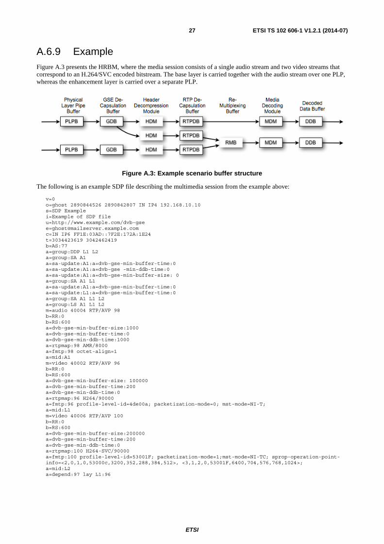
ETSI
ETSI TS 102 606-1 V1.2.1 (2014-07)27
A.6.9 Example Figure A.3 presents the HRBM, where the media session consists of a single audio stream and two video streams that correspond to an H.264/SVC encoded bitstream. The base layer is carried together with the audio stream over one PLP, whereas the enhancement layer is carried over a separate PLP.
Figure A.3: Example scenario buffer structure
The following is an example SDP file describing the multimedia session from the example above:
v=0 o=ghost 2890844526 2890842807 IN IP4 192.168.10.10 s=SDP Example i=Example of SDP file u=http://www.example.com/dvb-gse [email protected] c=IN IP6 FF1E:03AD::7F2E:172A:1E24 t=3034423619 3042462419 b=AS:77 a=group:DDP L1 L2 a=group:SA A1 a=sa-update:A1:a=dvb-gse-min-buffer-time:0 a=sa-update:A1:a=dvb-gse -min-ddb-time:0 a=sa-update:A1:a=dvb-gse-min-buffer-size: 0 a=group:SA A1 L1 a=sa-update:A1:a=dvb-gse-min-buffer-time:0 a=sa-update:L1:a=dvb-gse-min-buffer-time:0 a=group:SA A1 L1 L2 a=group:LS A1 L1 L2 m=audio 40004 RTP/AVP 98 b=RR:0 b=RS:600 a=dvb-gse-min-buffer-size:1000 a=dvb-gse-min-buffer-time:0 a=dvb-gse-min-ddb-time:1000 a=rtpmap:98 AMR/8000 a=fmtp:98 octet-align=1 a=mid:A1 m=video 40002 RTP/AVP 96 b=RR:0 b=RS:600 a=dvb-gse-min-buffer-size: 100000 a=dvb-gse-min-buffer-time:200 a=dvb-gse-min-ddb-time:0 a=rtpmap:96 H264/90000 a=fmtp:96 profile-level-id=4de00a; packetization-mode=0; mst-mode=NI-T; a=mid:L1 m=video 40006 RTP/AVP 100 b=RR:0 b=RS:600 a=dvb-gse-min-buffer-size:200000 a=dvb-gse-min-buffer-time:200 a=dvb-gse-min-ddb-time:0 a=rtpmap:100 H264-SVC/90000 a=fmtp:100 profile-level-id=53001F; packetization-mode=1;mst-mode=NI-TC; sprop-operation-point-info=<2,0,1,0,53000c,3200,352,288,384,512>, <3,1,2,0,53001F,6400,704,576,768,1024>; a=mid:L2 a=depend:97 lay L1:96

ETSI
ETSI TS 102 606-1 V1.2.1 (2014-07)28
Annex B (informative): Encapsulator Processing
B.1 Encapsulator/Scheduler Functions Figure B.1 shows a block diagram highlighting the key functions related to the scheduling and encapsulation process, which take place at the transmitter. This high-level representation is not intended to specify a GSE encapsulation implementation, but rather to exemplify the main functional elements and their interrelations.
Figure B.1: Encapsulator/scheduler block diagram
First, the un-shaded blocks are discussed. The second step will analyze the shaded blocks, which are an aggregation of the elementary plain blocks, analyzing how additional interrelations and joint operation can bring significant benefits in terms of system efficiency.
Incoming IP or other network layer packets are processed and routed into different buffers depending on their destination and QoS requirements/priority. When an ACM system is considered, the channel quality of the destination terminal will also need to be taken into account. Following such classification, the scheduler selects packets to be transmitted, based on a specific scheduling policy, which in general aims at maximizing capacity while guaranteeing achievement of individual QoS targets.
The PDUs, output from the scheduler, will be fragmented and encapsulated (including the addition of any required extension headers) to form GSE Packets (PDU encapsulator/slicer), and further allocated into Base Band frames (GSE Packets scheduler). The generated Base Band frames are then sent to the modulator, together with an indication of the corresponding transmission parameters (coding rate, modulation format) if ACM is utilized.
A design that fully exploits the Base Band frame payload minimizing padding overhead is possible when knowledge of the frame length is used for ad-hoc fragmentation of the incoming encapsulated PDUs (see figure 1). In this case, there is a relation between the function of PDU encapsulation and fragmentation and the GSE Packet allocation into the Base Band frame; a feedback from the GSE Packet scheduler to the PDU encapsulator may be required. Therefore the two functions may be thought of as being jointly performed by a single and more complex block, named here GSE encapsulator.
When ACM is utilized, each receiver will in general only decode a part of the transmitted data stream, and in particular only the frames transmitted with modulation and coding parameters fitting the receiver terminal channel quality. This is the reason why it is necessary for the scheduling of GSE Packets into frames to take into account the ACM information related to the terminal to which a particular PDU was addressed.

ETSI
ETSI TS 102 606-1 V1.2.1 (2014-07)29
A scheduler in the GSE encapsulator, which performs smart placement of GSE Packets in the Base Band frames, allows for optimizing system efficiency. The rational is exemplified in figures B.2 and B.3, where a study case is proposed. In figure B.2, PDU1, PDU2 and PDU3 form a sequence of PDUs, pre-scheduled by the outer scheduler. The term MODCOD indicates the modulation format and coding rate associated to a given PDU. This assumes that the efficiency of MODCOD2 is higher than the one of MODCOD1, i.e. MODCOD1 corresponds to a more robust transmission. The PDUs are encapsulated and scheduled into Base Band Frames by the GSE encapsulator.
Figure B.2: Disjoint encapsulation/scheduling
When a PDU is fragmented, for example to optimally fill the Base Band Frame Data Field, as in the case for the PDU2 in the above example, the remaining PDU fragment is encapsulated in an independent GSE Packet, which is transmitted in one of the following Base Band Frames. However, if no smart scheduling strategy is utilized, the generated GSE Packet will be scheduled for a Base Band Frame, together with other pre-scheduled encapsulated PDUs. Since the transmission parameters are constant for the same frame, the encapsulator will "downgrade" to MODCOD 1 the fragment of the following PDU required to fill the frame. This implies a degradation of the instantaneous channel capacity with respect to the achievable one, due to the disjoint scheduling and encapsulation process. Figure B.3 shows how a joint operation of scheduling and encapsulation can eliminate link efficiency losses and can achieve a better system efficiency.
Figure B.3: Joint scheduling/encapsulation
The issue of distributing scheduling functions between the outer scheduler and the inner GSE Packets scheduler is not addressed in the present document. It is dependent both on the selected scheduling routine and on implementation issues. However, GSE allows for a fully flexible scheduling of encapsulated PDU and PDU fragments into the Base Band Frames, provided that GSE Packets including fragments of the same PDU are transmitted in order. With a joint optimized operation of scheduler and encapsulation, the overall system efficiency can be optimized.

ETSI
ETSI TS 102 606-1 V1.2.1 (2014-07)30
B.2 Use of the Label Type Indicator The Label Type Indicator allows an Encapsulator to notify the receivers about the format of the NPA address that it should use for the filtering of received GSE Packets. The presence of a Label Type Indicator in each GSE Packet for a series of GSE Packets destined for the same NPA address is redundant, and may be optimized by using the LT value of "11". An Encapsulator will use the Label Type value of "11" only within the scope of one single frame, and never for the first GSE packet of a frame. This rule prevents ambiguities in the case of frame loss.

ETSI
ETSI TS 102 606-1 V1.2.1 (2014-07)31
Annex C (informative): GSE Packet Format Examples Figures C.1 to C.5 show example study cases of GSE Packet format.
Figure C.1: GSE Packet carrying a full, unfragmented PDU with a 6 byte NPA Address
Figure C.2: GSE Packet carrying a full, unfragmented PDU with a 3 byte NPA Address
Figure C.3: A sequence of GSE Packets carrying the start, continuation and end of a PDU

ETSI
ETSI TS 102 606-1 V1.2.1 (2014-07)32
Figure C.4: Concatenated GSE Packets: GSE Packet formats and allocation in a Base Band Frame
Figure C.5: GSE encapsulation of MPEG signalling packets [9]

ETSI
ETSI TS 102 606-1 V1.2.1 (2014-07)33
Annex D (normative): GSE-Lite Profile
D.1 Overview In order to reduce the memory and processing requirements at both transmitter and the receiver, the GSE-Lite profile has been conceived to provide a simple yet completely functional sub-set of GSE. This profile is particularly aimed at consumer receivers, where cost is a major design factor. The GSE-Lite profile has been created considering the increased use of IP packets, however it retains many of the generic features of the full GSE profile.
The major features of the GSE-Lite profile are outlined in Table D.1.
Table D.1: GSE-Lite profile features
Feature GSE-Lite Profile GSE Profile Maximum Memory approx. 7,2 [kB] approximately 16 [MB] Maximum Latency 64 [Baseband Frames] 256 [Baseband Frames]
While not an exhaustive list, GSE-Lite is particularly targeted at the second generation DVB physical layer specifications DVB-S2, DVB-C2, DVB-T2 and DVB-NGH.
Unless explicitly stated in this annex, no further restrictions on the use of GSE-Lite shall apply.
D.2 GSE-Lite Profile Restrictions The GSE-Lite profile shall consist of the following restrictions on the full GSE profile:
1) Size Restrictions
a) The maximum PDU size shall be 1 800 bytes.
b) The maximum size of a GSE packet, including extension headers, shall not exceed the maximum PDU size.
2) Fragmentation Restrictions
a) The maximum number of concurrent Fragmentation Identifiers (Frag ID) shall be 4.
b) The maximum number of PDU fragments with the same Frag ID shall be 6.
c) Transmission of PDU fragments of a particular Frag ID shall be completed within a period of 64 baseband frames from the start of first fragment.
These rules are summarized and compared with the full GSE profile in Table D.2.
Table D.2: Comparison of GSE-Lite and GSE profile parameters
Parameter GSE-Lite profile GSE profile Max. PDU Size 1 800 bytes 65 536 bytes Max. GSE Packet Size 1 800 bytes 4 096 bytes Max. Fragmentation Identifiers 4 256 Max. Fragments for PDU 6 Effectively unlimited Max. Delay for Final Fragment Transmission 64 Baseband Frames 256 Baseband Frames

ETSI
ETSI TS 102 606-1 V1.2.1 (2014-07)34
D.2.1 PDU size The maximum PDU size has been specified to be 1 800 bytes in the GSE-Lite profile. This value is slightly larger than the common maximum MTU size of an Ethernet v2 IP packet (1 500 bytes). The extra bytes have been allowed for additional headers and engineering margin. Since the maximum PDU size in GSE-Lite is less than 4 096 bytes (the maximum GSE packet size in the full GSE-profile), the maximum GSE packet size has also been reduced. In this manner, the maximum memory required for buffering fragmented PDUs has been significantly reduced to approximately 7,2 kB (4 fragmentation IDs × 1 800 bytes) in the GSE-Lite profile, from approximately 16 MB in the full GSE profile.
Since the maximum PDU size in GSE-Lite has been reduced, fragmentation of the PDU to meet the maximum GSE packet size of 4 kB is no longer necessary, reducing the processing burden and increasing the header efficiency since fragmentation need not be signalled. However, depending on the physical layer and mode that are used, there are cases when fragmentation of the PDU may be useful or needed, and thus a small amount of fragmentation is permitted in GSE-Lite.
D.2.2 Fragmentation The maximum number of fragments has been chosen to cover the fragmentation of the smallest baseband frame in DVB-T2/C2/S2. This occurs in DVB-S2 where the minimum length of a baseband frame (Kbch) is 3 072 bits (384 bytes), for a short code rate of 1/4. In addition the baseband header size (10 bytes) and for ACM modes a 4 byte CRC also needs to be considered, meaning the minimum data field length is 370 bytes. Therefore, 5 fragments (5 fragments × 370 bytes = 1 850 bytes) will allow the largest GSE-Lite packet to be fragmented, if so needed. To allow some margin, 6 fragments has been chosen as the maximum allowed for GSE-Lite.
Fragmentation of PDUs should not lead to excessive transmission delay. By reducing the maximum time within which the final PDU fragment shall be transmitted, the worst case delay is reduced. In GSE-Lite, considering practical usage examples, the maximum delay for the final fragment transmission has been chosen as 64 baseband frames.
NOTE: Fragmentation rules apply to the GSE layer only. Fragmentation outside of the GSE layer (sometimes referred to as slicing or physical layer fragmentation) may be performed as long as it is transparent to the GSE layer.
The maximum number of concurrent Fragmentation Identifiers (Frag ID) shall be 4 for each destination address that it binds to. Examples of destinations include the broadcast mode "LT==10", or a specific 3-byte or 6-byte label. The minimum number of concurrent Frag IDs that need to be supported by a receiver is one; see annex A for details.
For maximum efficiency and to provide a simple receiver mode where PDU fragmentation is not necessary, it is required that when HEM (High Efficiency Mode) is used on the physical layer, the maximum number of concurrent GSE fragments is 1, which means that PDU fragmentation is not performed on the GSE layer. In this case it is expected that physical layer slicing will be performed as necessary.
ETSI
ETSI TS 102 606-1 V1.2.1 (2014-07)35
Annex E (informative): Bibliography
• ETSI EN 301 790: "Digital Video Broadcasting (DVB); Interaction channel for satellite distribution systems".
• ETSI EN 300 468: "Digital Video Broadcasting (DVB); Specification for Service Information (SI) in DVB systems".
• ETSI TR 101 162: "Digital Video Broadcasting (DVB); Allocation of identifiers and codes for Digital Video Broadcasting (DVB) systems"

ETSI
ETSI TS 102 606-1 V1.2.1 (2014-07)36
History
Document history
V1.1.1 October 2007 Publication as TS 102 606
V1.2.1 July 2014 Publication