trustability board mount pressure sensors · pdf filedatasheet. 2 trustability ... compared...
TRANSCRIPT

TruStability® Board Mount Pressure SensorsHSC Series—High Accuracy, Compensated/Amplified±1.6 mbar to ±10 bar | ±160 Pa to ±1 MPa | ±0.5 inH2O to ±150 psiDigital or Analog Output
Datasheet
2 sensing.honeywell.com
TruStability® Board Mount Pressure Sensors The TruStability® High Accuracy Silicon Ceramic (HSC) Series is a piezoresistive silicon pressure sensor offering a ratiometric analog or digital output for reading pressure over the specified full scale pressure span and temperature range.
The HSC Series is fully calibrated and temperature compensated for sensor offset, sensitivity, temperature effects, and non-linearity using an on-board Application Specific Integrated Circuit (ASIC). Calibrated output values for pressure are updated at approximately 1 kHz for analog and 2 kHz for digital.
The HSC Series is calibrated over the temperature range of 0 °C to 50 °C [32 °F to 122 °F]. The sensor is characterized for operation from a single power supply of either 3.3 Vdc or 5.0 Vdc.
These sensors measure absolute, gage, or differential pressures. The absolute versions have an internal vacuum reference and an output value proportional to absolute pressure. Gage versions are referenced to atmospheric pressure and provide an output proportional to pressure variations from atmosphere. Differential versions allow measurement of pressure between the two pressure ports.
The TruStability® pressure sensors are intended for use with non-corrosive, non-ionic gases, such as air and other dry gases. Available options extend the performance of these sensors to non-corrosive, non-ionic liquids for pressure ranges above 40 mbar | 4 kPa | 20 inH2O.
All products are designed and manufactured according to ISO 9001 standards.
stability • accuracy • flexibility • small size
What makes our sensors better? • Stability and reliability
• Industry-leading accuracy of ±0.25 %FSS BFSL
• Port and housing options simplify integration
• Wide pressure range, from ±1.6 mbar to ±10 bar | ±160 Pa to ±1 MPa | ±0.5 inH2O to ±150 psi
• Small package size
• Extremely low power consumption
,Table of ContentsFeatures and Benefits . . . . . . . . . . . . . . . . . . 3-5
Potential Applications . . . . . . . . . . . . . . . . . . . . 6
General Specifications . . . . . . . . . . . . . . . . . 7-8
Analog Operating Specifications . . . . . . . . . . . 9
Digital Operating Specifications . . . . . . . . . . . 10
Transfer Function Limits . . . . . . . . . . . . . . . . . 11
Total Error Band Values . . . . . . . . . . . . . . . . . 12
Nomenclature and Order Guide . . . . . . . . . . . 13
Pressure Range Specifications
±1.6 mbar to ±10 bar . . . . . . . . . . . . . . . . . . 14
±160 Pa to ±1 MPa . . . . . . . . . . . . . . . . . . . . 15
±0.5 inH2O to ±150 psi . . . . . . . . . . . . . . . . . 16
Available Standard Configurations . . . . . . .17-18
Dimensional Drawings
DIP Packages . . . . . . . . . . . . . . . . . . . . . 19-21
SMT Packages . . . . . . . . . . . . . . . . . . . 21-24
SIP Packages . . . . . . . . . . . . . . . . . . . . . 24-29
Pinouts, PCB Layouts . . . . . . . . . . . . . . . . . . . 30
TruStability® Board Mount Pressure Sensors
Portfolio Overview . . . . . . . . . . . . . . . . . . . . . 31
Additional Information. . . . . . . . . . . . . . . . . . . 32
3sensing.honeywell.com
ProPrietAry Honeywell teCHnologyCombines high sensitivity with high overpressure and burst pressure while providing industry leading stability—performance factors that are difficult to achieve in the same product; this gives the customer more flexibility in sensor implementation and reduces the customer design requirements for protecting the sensor without sacrificing the ability to sense very small changes in pressure.
ProteCteD By MUltiPle gloBAl PAtentS
inDUStry-leADing long-terM StABilityEven after long-term use and thermal extremes, the sensor’s stability remains best in class:
• Minimizes system calibration needs. • Improves system performance. • Helps support system uptime by minimizing the need to service or replace the sensor during its application life.
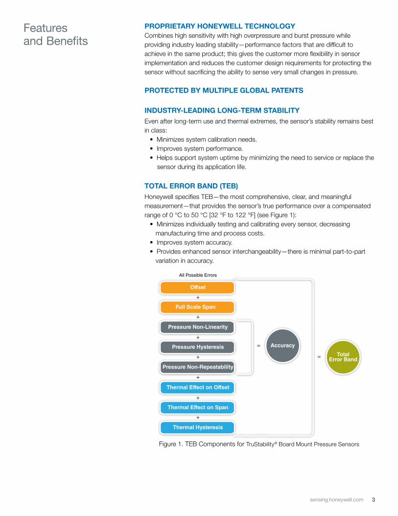
totAl error BAnD (teB)Honeywell specifies TEB—the most comprehensive, clear, and meaningful measurement—that provides the sensor’s true performance over a compensated range of 0 °C to 50 °C [32 °F to 122 °F] (see Figure 1):
• Minimizes individually testing and calibrating every sensor, decreasing manufacturing time and process costs.
• Improves system accuracy. • Provides enhanced sensor interchangeability—there is minimal part-to-part
variation in accuracy.
Features and Benefits
+
+
+
+
+
+
+
Pressure Hysteresis
+
+
Pressure Non-Repeatability
All Possible Errors
+
+
+
Offset
+
+
Full Scale Span
+
+
Thermal Effect on Offset
+
+
Thermal Effect on Span
+
Thermal Hysteresis
TotalError Band
Accuracy=
=
Pressure Non-Linearity
Figure 1. TEB Components for TruStability® Board Mount Pressure Sensors
4 sensing.honeywell.com
Features and Benefits
inDUStry-leADing ACCUrACyExtremely tight accuracy of ±0.25 %FSS BFSL (Full Scale Span Best Fit Straight Line) reduces software needed to correct system inaccuracies, minimizing system design time:
• Avoids additional customer calibration. • Helps to improve system efficiency. • Often simplifies software development.
HigH BUrSt PreSSUreS• Promotes system reliability and reduces potential system downtime. • Can simplify the design process.
HigH working PreSSUre rAngeS Allows ultra-low pressure sensors to be used continuously well above the calibrated pressure range.
inDUStry-leADing flexiBilityModular, flexible design with many package styles (with the same industry-leading stability), pressure ports, and options simplify integration into the device manufacturer’s application.
wiDe vAriety of PreSSUre rAngeSFrom ±1.6 mbar to ±10 bar | ±160 Pa to ±1 MPa | ±0.5 inH2O to 150 psi provide support for many unique applications.
MeetS iPC/JeDeC J-StD-020D.1 MoiStUre SenSitivity level 1 reqUireMentS
• Allows the customer to avoid the thermal and mechanical damage during solder reflow attachment and/or repair that lesser rated products would incur.
• Allows unlimited floor life when stored as specified (<30 ºC/85 %RH), simplifying storage and reducing scrap.
• Never requires lengthy bakes prior to reflow.• Stable and usable shortly after reflow process allows for lean manufacturing.
oPtionAl internAl DiAgnoStiC fUnCtionS• May reduce the need for redundant sensors in the system.• Detects most internal failures including burst sensors.
energy effiCientExtremely low power consumption (less than 10 mW, typ.):
• Reduces system power requirements. • Enables extended battery life. • Optional sleep mode available upon special request.
5sensing.honeywell.com
Features and Benefits
oUtPUt: rAtioMetriC AnAlog; i2C- or SPi-CoMPAtiBle 14-Bit DigitAl oUtPUt (Min. 12-Bit SenSor reSolUtion)Accelerates performance through reduced conversion requirements and the convenience of direct interface to microprocessors.
SMAll SizeMiniature 10 mm x 10 mm [0.39 in x 0.39 in] package is very small when compared to many board mount pressure sensors:
• Occupies less area on the PCB. • Typically allows for easy placement on crowded PCBs or in small devices.
reACH AnD roHS CoMPliAnt
liqUiD MeDiA oPtion• Provides robustness in environments with condensing humidity.• Compatible with a variety of non-ionic fluids. • Available for pressure ranges above 40 mbar | 4 kPa | 20 inH20.
6 sensing.honeywell.com
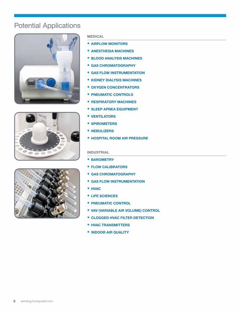
MeDiCAl
• Airflow MonitorS
• AneStHeSiA MACHineS
• BlooD AnAlySiS MACHineS
• gAS CHroMAtogrAPHy
• gAS flow inStrUMentAtion
• kiDney DiAlySiS MACHineS
• oxygen ConCentrAtorS
• PneUMAtiC ControlS
• reSPirAtory MACHineS
• SleeP APneA eqUiPMent
• ventilAtorS
• SPiroMeterS
• neBUlizerS
• HoSPitAl rooM Air PreSSUre
inDUStriAl
• BAroMetry
• flow CAliBrAtorS
• gAS CHroMAtogrAPHy
• gAS flow inStrUMentAtion
• HvAC
• life SCienCeS
• PneUMAtiC Control
• vAv (vAriABle Air volUMe) Control
• CloggeD HvAC filter DeteCtion
• HvAC trAnSMitterS
• inDoor Air qUAlity
Potential Applications
7sensing.honeywell.com
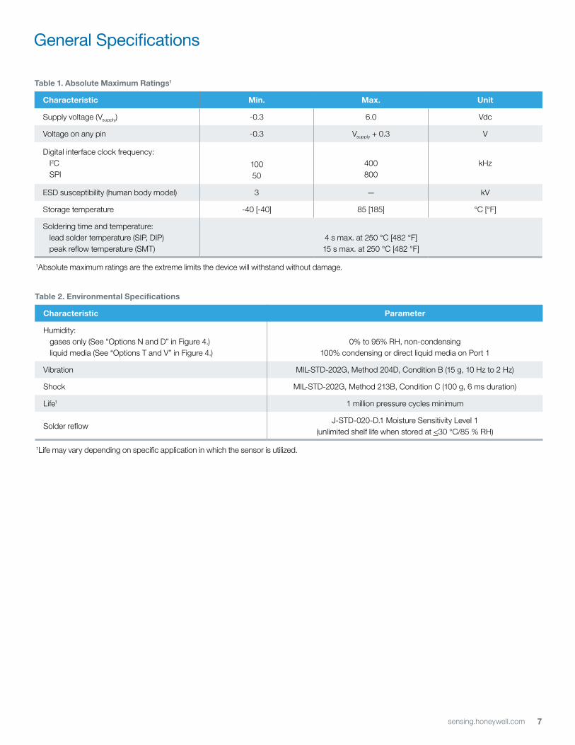
General Specifications
table 1. Absolute Maximum ratings1
Characteristic Min. Max. Unit
Supply voltage (Vsupply) -0.3 6.0 Vdc
Voltage on any pin -0.3 Vsupply + 0.3 V
Digital interface clock frequency: I2C SPI
10050
400800
kHz
ESD susceptibility (human body model) 3 — kV
Storage temperature -40 [-40] 85 [185] °C [°F]
Soldering time and temperature: lead solder temperature (SIP, DIP) peak reflow temperature (SMT)
4 s max. at 250 °C [482 °F]15 s max. at 250 °C [482 °F]
1Absolute maximum ratings are the extreme limits the device will withstand without damage.
table 2. environmental Specifications
Characteristic Parameter
Humidity: gases only (See “Options N and D” in Figure 4.) liquid media (See “Options T and V” in Figure 4.)
0% to 95% RH, non-condensing100% condensing or direct liquid media on Port 1
Vibration MIL-STD-202G, Method 204D, Condition B (15 g, 10 Hz to 2 Hz)
Shock MIL-STD-202G, Method 213B, Condition C (100 g, 6 ms duration)
Life1 1 million pressure cycles minimum
Solder reflowJ-STD-020-D.1 Moisture Sensitivity Level 1
(unlimited shelf life when stored at <30 °C/85 % RH)
1Life may vary depending on specific application in which the sensor is utilized.

8 sensing.honeywell.com
CAUTIONPRODUCT DAMAGE FOR SENSORS WITH LIQUID MEDIA OPTION (ONLY AVAILABLE 60 MBAR | 6 KPA | 1 PSI AND ABOVE) • Ensure liquid media is applied to Port 1 only; Port 2 is not compatible with liquids.• Ensure liquid media contains no particulates. All TruStability® sensors are dead-ended devices. Particulates can accumulate
inside the sensor, causing damage or affecting sensor output.• Recommend that the sensor be positioned with Port 1 facing downwards; any particulates in the system are less likely to enter
and settle within the pressure sensor if it is in this position.• Ensure liquid media does not create a residue when dried; build-up inside the sensor may affect sensor output. Rinsing of a
dead-ended sensor is difficult and has limited effectiveness for removing residue.• Ensure liquid media are compatible with wetted materials. Non-compatible liquid media will degrade sensor performance and
may lead to sensor failure.Failure to comply with these instructions may result in product damage.
table 4. Sensor Pressure types
Pressure type Description
Absolute Output is proportional to the difference between applied pressure and a built-in vacuum reference.
Differential Output is proportional to the difference between the pressures applied to each port (Port 1 – Port 2).
Gage Output is proportional to the difference between applied pressure and atmospheric (ambient) pressure.
General Specifications
table 3. wetted Materials1
Component Port 1 (Pressure Port) Port 2 (reference Port)
Ports and covers high temperature polyamide high temperature polyamide
Substrate alumina ceramic alumina ceramic
Adhesives epoxy, silicone epoxy, silicone
Electronic components ceramic, silicon, glass, solder silicon, glass, gold
1Contact Honeywell Customer Service for detailed material information.
9sensing.honeywell.com
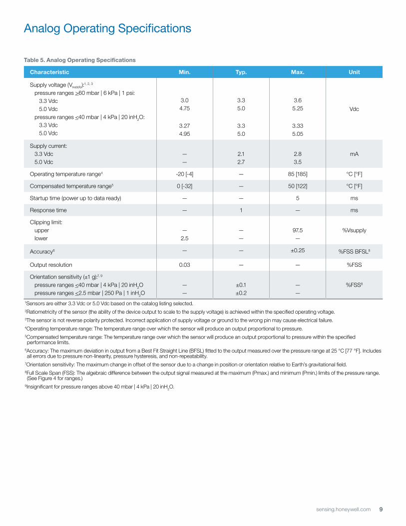
table 5. Analog operating Specifications
Characteristic Min. typ. Max. Unit
Supply voltage (Vsupply):1, 2, 3
pressure ranges >60 mbar | 6 kPa | 1 psi: 3.3 Vdc 5.0 Vdc pressure ranges <40 mbar | 4 kPa | 20 inH2O: 3.3 Vdc 5.0 Vdc
3.04.75
3.274.95
3.35.0
3.35.0
3.65.25
3.335.05
Vdc
Supply current: 3.3 Vdc 5.0 Vdc
——
2.12.7
2.83.5
mA
Operating temperature range4 -20 [-4] — 85 [185] °C [°F]
Compensated temperature range5 0 [-32] — 50 [122] °C [°F]
Startup time (power up to data ready) — — 5 ms
Response time — 1 — ms
Clipping limit: upper lower
—2.5
——
97.5—
%Vsupply
Accuracy6 — — ±0.25 %FSS BFSL8
Output resolution 0.03 — — %FSS
Orientation sensitivity (±1 g):7, 9
pressure ranges <40 mbar | 4 kPa | 20 inH2O pressure ranges <2.5 mbar | 250 Pa | 1 inH2O
——
±0.1±0.2
——
%FSS8
1Sensors are either 3.3 Vdc or 5.0 Vdc based on the catalog listing selected.2Ratiometricity of the sensor (the ability of the device output to scale to the supply voltage) is achieved within the specified operating voltage.3The sensor is not reverse polarity protected. Incorrect application of supply voltage or ground to the wrong pin may cause electrical failure. 4Operating temperature range: The temperature range over which the sensor will produce an output proportional to pressure.5Compensated temperature range: The temperature range over which the sensor will produce an output proportional to pressure within the specified performance limits.
6Accuracy: The maximum deviation in output from a Best Fit Straight Line (BFSL) fitted to the output measured over the pressure range at 25 °C [77 °F]. Includes all errors due to pressure non-linearity, pressure hysteresis, and non-repeatability.
7Orientation sensitivity: The maximum change in offset of the sensor due to a change in position or orientation relative to Earth’s gravitational field.8Full Scale Span (FSS): The algebraic difference between the output signal measured at the maximum (Pmax.) and minimum (Pmin.) limits of the pressure range. (See Figure 4 for ranges.)
9Insignificant for pressure ranges above 40 mbar | 4 kPa | 20 inH2O.
Analog Operating Specifications

10 sensing.honeywell.com
table 7. Sensor output at Significant Percentages (Digital versions only)
% output Digital Counts (decimal) Digital Counts (hex)
0 0 0x0000
10 1638 0x0666
50 8192 0x2000
90 14746 0x399A
100 16383 0x3FFF
table 6. Digital operating Specifications
Characteristic Min. typ. Max. Unit
Supply voltage (Vsupply):1, 2, 3
pressure ranges >60 mbar | 6 kPa | 1 psi: 3.3 Vdc 5.0 Vdc pressure ranges <40 mbar | 4 kPa | 20 inH2O: 3.3 Vdc 5.0 Vdc
3.04.75
3.274.95
3.35.0
3.35.0
3.65.25
3.335.05
Vdc
Supply current: 3.3 Vdc 5.0 Vdc
——
3.13.7
3.94.6
mA
Operating temperature range4 -20 [-4] — 85 [185] °C [°F]
Compensated temperature range5 0 [-32] — 50 [122] °C [°F]
Startup time (power up to data ready) — — 3 ms
Response time — 0.46 — ms
SPI/I2C voltage level: low high
—80
——
20—
%Vsupply
Pull up on SDA/MISO, SCL/SCLK, SS 1 — — kOhm
Accuracy6 — — ±0.25 %FSS BFSL8
Output resolution 12 — — bits
Orientation sensitivity (±1 g):7, 9
pressure ranges <40 mbar | 4 kPa | 20 inH2O pressure ranges <2.5 mbar | 250 Pa | 1 inH2O
——
±0.1±0.2
——
%FSS8
1Sensors are either 3.3 Vdc or 5.0 Vdc based on the catalog listing selected.2Ratiometricity of the sensor (the ability of the device output to scale to the supply voltage) is achieved within the specified operating voltage.3The sensor is not reverse polarity protected. Incorrect application of supply voltage or ground to the wrong pin may cause electrical failure. 4Operating temperature range: The temperature range over which the sensor will produce an output proportional to pressure.5Compensated temperature range: The temperature range over which the sensor will produce an output proportional to pressure within the specified performance limits.
6Accuracy: The maximum deviation in output from a Best Fit Straight Line (BFSL) fitted to the output measured over the pressure range at 25 °C [77 °F]. Includes all errors due to pressure non-linearity, pressure hysteresis, and non-repeatability.
7Orientation sensitivity: The maximum change in offset of the sensor due to a change in position or orientation relative to Earth’s gravitational field.8Full Scale Span (FSS): The algebraic difference between the output signal measured at the maximum (Pmax.) and minimum (Pmin.) limits of the pressure range. (See Figure 4 for ranges.)
9Insignificant for pressure ranges above 40 mbar | 4 kPa | 20 inH2O.
Digital Operating Specifications
11sensing.honeywell.com
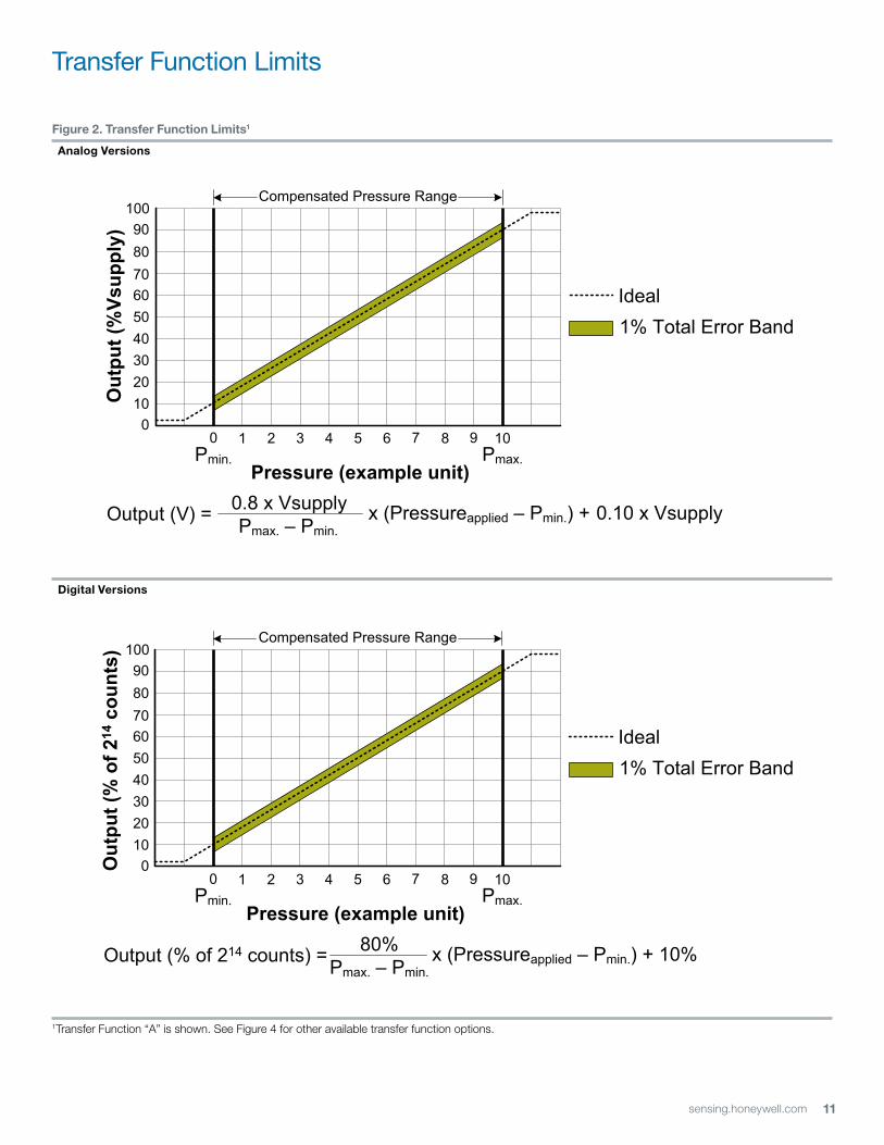
Transfer Function Limits
figure 2. transfer function limits1
Analog versions
Digital versions
1Transfer Function “A” is shown. See Figure 4 for other available transfer function options.
0
102030405060708090
100
1 2 3 4 5 6 7 8 9 10
1% Total Error Band
0
Ideal
Pmin. Pmax.
Compensated Pressure Range
Pressure (example unit)
Out
put (
%Vs
uppl
y)
0.8 x VsupplyPmax. – Pmin.
Output (V) = x (Pressureapplied – Pmin.) + 0.10 x Vsupply
80% Pmax. – Pmin.
Output (% of 214 counts) = x (Pressureapplied – Pmin.) + 10%
Out
put (
% o
f 214
cou
nts)
0
102030405060708090
100
1 2 3 4 5 6 7 8 9 10
Pressure (example unit)
1% Total Error Band
0
Ideal
Pmin. Pmax.
Compensated Pressure Range
12 sensing.honeywell.com
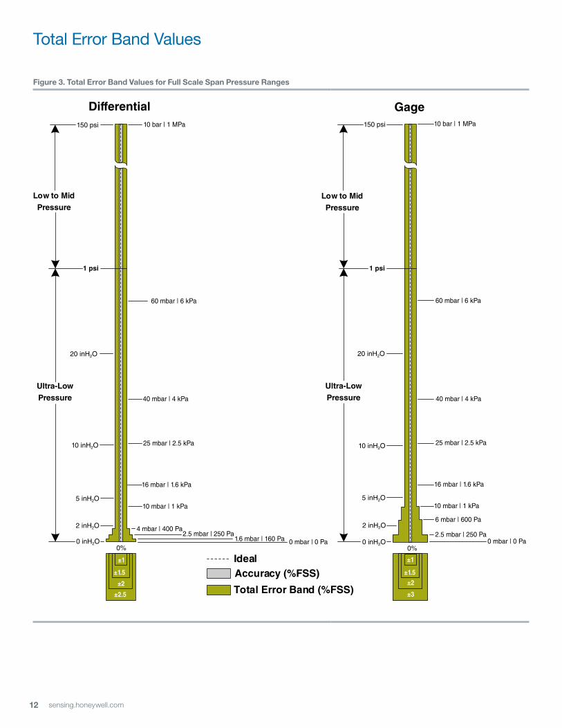
Total Error Band Values
figure 3. total error Band values for full Scale Span Pressure ranges
4 mbar10 inH2030 inH20
Pres
sure
16x
5x
11x
18x
Calibrated Pressure Range
15x
30x
84x
159x
50x
250x
500 inH20
1000 mbar
550 inH20
Calibrated Pressure Range (x)
Working PressureRange
Overpressure(maximum)
Burst Pressure(minimum)
GageDifferential
Low to MidPressure
Ideal
Total Error Band (%FSS)
Accuracy (%FSS)
2.5 mbar | 250 Pa4 mbar | 400 Pa
1.6 mbar | 160 Pa
±1
±1.5
±2
±2.5
16 mbar | 1.6 kPa
25 mbar | 2.5 kPa
40 mbar | 4 kPa
60 mbar | 6 kPa
10 bar | 1 MPa
Low to MidPressure
Ultra-LowPressure
Ultra-LowPressure
2.5 mbar | 250 Pa
6 mbar | 600 Pa
±1
±1.5
±2
±3
10 mbar | 1 kPa
2 inH2O
5 inH2O
10 inH2O
20 inH2O
150 psi
2 inH2O
5 inH2O
10 inH2O
20 inH2O
150 psi
0 inH2O 0 mbar | 0 Pa 0 inH2O 0 mbar | 0 Pa
10 bar | 1 MPa
16 mbar | 1.6 kPa
25 mbar | 2.5 kPa
40 mbar | 4 kPa
60 mbar | 6 kPa
0% 0%
1 psi 1 psi
10 mbar | 1 kPa
13sensing.honeywell.com
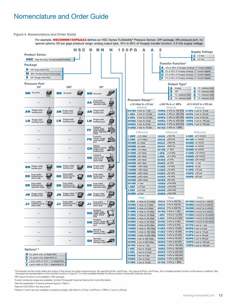
figure 4. nomenclature and order guide
Nomenclature and Order Guide
H S C D N N N 1 5 0 P G A A 3Product Series
Package
008B
Pressure PortDIP
HSC High Accuracy, Compensated/Amplified
Options5, 6
SMT
NN
AADual axialbarbed ports,opposite sides
SIP
AN
LN
FFFastenermount, dual axial barbed ports, opposite sides
FNFastenermount, single axial barbed port
GNRibbedfastener mount,single axialbarbed port
NBFastenermount, dual axial ports, same side
Single radialbarbed portRN
HHFastenermount, dualradial barbedports, same side
HNFastenermount, singleradial barbedport
MNManifoldmount, outerdiameter seal
Single axial barbed port
Single axial barbless port
No portsNN
AN
LN
Single radialbarbed port
Dual radialbarbed ports,same side
Dual radialbarbed ports,opposite sides
RN
RR
DR
Single axial barbed port
Single axial barbless port
No portsNN
AN
LN
Single radialbarbed port
Dual radialbarbed ports,same side
Dual radialbarbed ports,opposite sides
RN
RR
DR
Single axial barbed port
Single axial barbless port
No ports
SNManifoldmount, innerdiameter seal
Dual radialbarbed ports,opposite sides
DR
Dual radialbarbed ports,same side
RR
Single radialbarbless port
Dual radialbarbless ports,same side
JN
JJ
Single radialbarbless port
Dual radialbarbless ports,same side
JN
JJDual radialbarbless ports,same side
JJ
Single radialbarbless portJN
D DIP (Dual Inline Pin)
M SMT (Surface Mount Technology)
S SIP (Single Inline Pin)
Output Type2
Supply Voltage
For example, HSCDNNN150PGAA3 de�nes an HSC Series TruStability® Pressure Sensor, DIP package, NN pressure port, nospecial options,150 psi gage pressure range, analog output type, 10% to 90% of Vsupply transfer function, 3.3 Vdc supply voltage.
Pressure Range3, 4
N Dry gases only, no diagnostics
D Dry gases only, diagnostics on
T Liquid media on Port 1, no diagnostics
V Liquid media on Port 1, diagnostics on
A Analog
S SPI
2 I2C, Address 0x28
3 I2C, Address 0x38
4 I2C, Address 0x48
5 I2C, Address 0x58
6 I2C, Address 0x68
7 I2C, Address 0x78
3 3.3 Vdc
5 5.0 Vdc
1The transfer function limits define the output of the sensor at a given pressure input. By specifying Pmin. and Pmax., the output at Pmin. and Pmax., the complete transfer function of the sensor is defined. See the graphical representations of the transfer function in the product datasheet, Figure 2. For other available transfer functions contact Honeywell Customer Service. 2SPI output function is not available in SIP package.3Custom pressure ranges are available. Contact Honeywell Customer Service for more information.4See the explanation of sensor pressure types in the product datasheet, Table 4. 5See the CAUTION in this document.6Options T and V are only available on pressure ranges ±60 mbar to ±10 bar | ±6 kPa to ±1 MPa | ±1 psi to ±150 psi.
±0.5 inH2O to ±150 psi±1.6 mbar to ±10 barAbsolute
015PA030PA060PA100PA150PA
Differential
Absolute001BA
1.6BA 2.5BA 004BA 006BA 010BA
Differential
Gage
0.5ND001ND 002ND004ND 005ND 010ND020ND 030ND 001PD 005PD 015PD 030PD 060PD
Gage001NG002NG004NG005NG010NG 020NG030NG001PG 005PG015PG030PG 060PG 100PG 150PG
1.6MD2.5MD 004MD 006MD 010MD
016MD 025MD 040MD
060MD 100MD 160MD 250MD 400MD 600MD 001BD 1.6BD 2.5BD 004BD
2.5MG004MG006MG010MG016MG025MG040MG060MG100MG160MG250MG400MG600MG001BG1.6BG2.5BG 004BG006BG 010BG
0 bar to 1 bar
0 bar to 1.6 bar
0 bar to 2.5 bar
0 bar to 4 bar
0 bar to 6 bar
0 bar to 10 bar
±1.6 mbar
±2.5 mbar
±4 mbar
±6 mbar
±10 mbar
±16 mbar
±25 mbar
±40 mbar
±60 mbar
±100 mbar
±160 mbar
±250 mbar
±400 mbar
±600 mbar
±1 bar
±1.6 bar
±2.5 bar
±4 bar
0 mbar to 2.5 mbar
0 mbar to 4 mbar
0 mbar to 6 mbar
0 mbar to 10 mbar
0 mbar to 16 mbar
0 mbar to 25 mbar
0 mbar to 40 mbar
0 mbar to 60 mbar
0 mbar to 100 mbar
0 mbar to 160 mbar
0 mbar to 250 mbar
0 bar to 400 mbar
0 bar to 600 mbar
0 bar to 1 bar
0 bar to 1.6 bar
0 bar to 2.5 bar
0 bar to 4 bar
0 bar to 6 bar
0 bar to 10 bar
±160 Pa to ±1 MPaAbsolute
100KA
160KA 250KA 400KA 600KA 001GA
Differential
Gage
160LD250LD 400LD600LD001KD
1.6KD2.5KD004KD006KD010KD016KD025KD040KD060KD100KD160KD250KD400KD
250LG400LG600LG001KG1.6KG2.5KG004KG006KG010KG016KG025KG040KG060KG100KG160KG250KG400KG600KG001GG
0 kPa to 100 kPa
0 kPa to 160 kPa
0 kPa to 250 kPa
0 kPa to 400 kPa
0 kPa to 600 kPa
0 kPa to 1 MPa
±160 Pa
±250 Pa
±400 Pa
±600 Pa
±1 kPa
±1.6 kPa
±2.5 kPa
±4 kPa
±6 kPa
±10 kPa
±16 kPa
±25 kPa
±40 kPa
±60 kPa
±100 kPa
±160 kPa
±250 kPa
±400 kPa
0 Pa to 250 Pa
0 Pa to 400 Pa
0 Pa to 600 Pa
0 kPa to 1 kPa
0 kPa to 1.6 kPa
0 kPa to 2.5 kPa
0 kPa to 4 kPa
0 kPa to 6 kPa
0 kPa to 10 kPa
0 kPa to 16 kPa
0 kPa to 25 kPa
0 kPa to 40 kPa
0 kPa to 60 kPa
0 kPa to 100 kPa
0 kPa to 160 kPa
0 kPa to 250 kPa
0 kPa to 400 kPa
0 kPa to 600 kPa
0 kPa to 1 MPa
0 inH2O to 1 inH2O
0 inH2O to 2 inH2O
0 inH2O to 4 inH2O
0 inH2O to 5 inH2O
0 inH2O to 10 inH2O
0 inH2O to 20 inH2O
0 inH2O to 30 inH2O
0 psi to 1 psi
0 psi to 5 psi
0 psi to 15 psi
0 psi to 30 psi
0 psi to 60 psi
0 psi to 100 psi
0 psi to 150 psi
±0.5 inH2O
±1 inH2O
±2 inH2O
±4 inH2O
±5 inH2O
±10 inH2O
±20 inH2O
±30 inH2O
±1 psi
±5 psi±15 psi
±30 psi
±60 psi
0 psi to 15 psi
0 psi to 30 psi
0 psi to 60 psi
0 psi to 100 psi
0 psi to 150 psi
Transfer Function1
ABCF
10% to 90% of Vsupply (analog), 214 counts (digital)
5% to 95% of Vsupply (analog), 214 counts (digital)
5% to 85% of Vsupply (analog), 214 counts (digital)
4% to 94% of Vsupply (analog), 214 counts (digital)
1The transfer function limits define the output of the sensor at a given pressure input. By specifying Pmin. and Pmax., the output at Pmin. and Pmax., the complete transfer function of the sensor is defined. See the graphical representations of the transfer function in Figure 2. For other available transfer functions contact Honeywell Customer Service.
2SPI output function is not available in SIP package.3Custom pressure ranges are available. Contact Honeywell Customer Service for more information.4See the explanation of sensor pressure types in Table 4. 5See the CAUTION in this document.6Options T and V are only available on pressure ranges ±60 mbar to ±10 bar | ±6 kPa to ±1 MPa | ±1 psi to ±150 psi.
14 sensing.honeywell.com
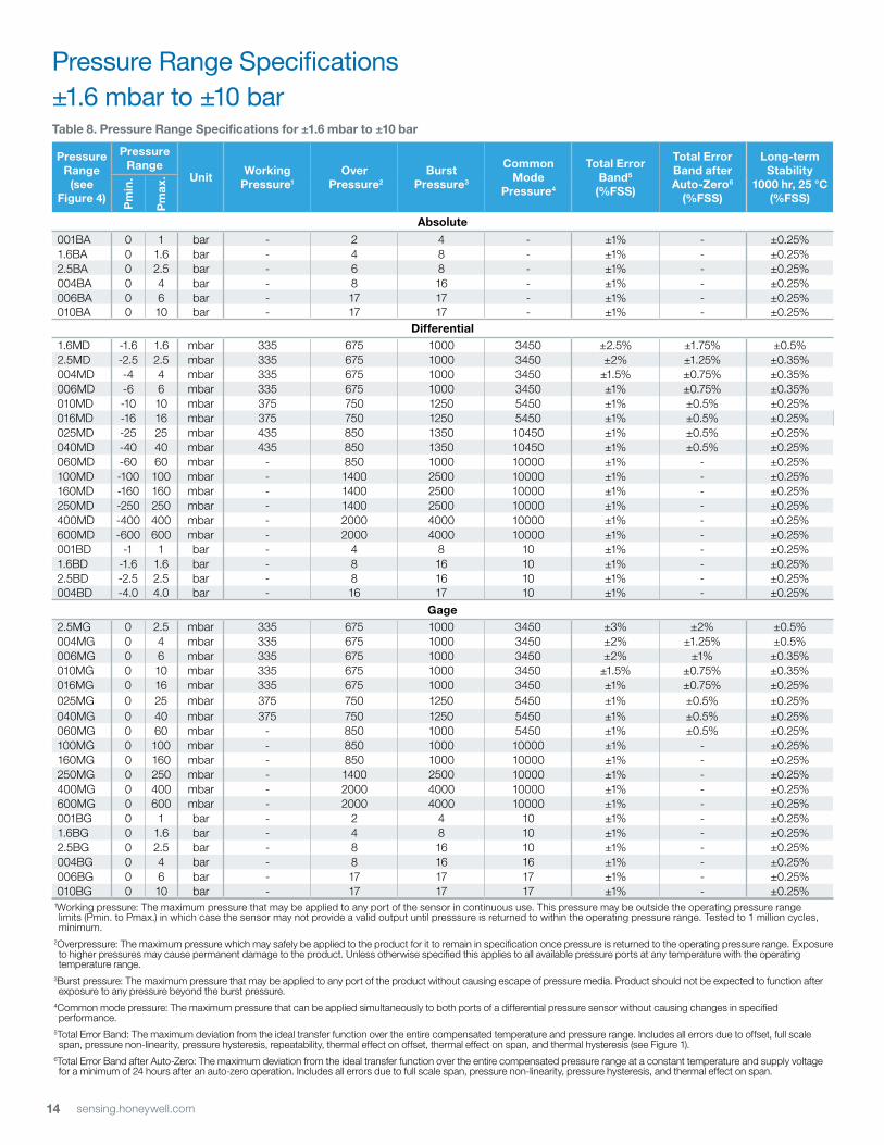
table 8. Pressure range Specifications for ±1.6 mbar to ±10 bar
Pressure range
(see figure 4)
Pressure range
Unitworking
Pressure1over
Pressure2Burst
Pressure3
Common Mode
Pressure4
total error Band5
(%fSS)
total error Band after Auto-zero6
(%fSS)
long-term Stability
1000 hr, 25 °C(%fSS)
Pm
in.
Pm
ax.
Absolute
001BA 0 1 bar - 2 4 - ±1% - ±0.25%1.6BA 0 1.6 bar - 4 8 - ±1% - ±0.25%2.5BA 0 2.5 bar - 6 8 - ±1% - ±0.25%004BA 0 4 bar - 8 16 - ±1% - ±0.25%006BA 0 6 bar - 17 17 - ±1% - ±0.25%010BA 0 10 bar - 17 17 - ±1% - ±0.25%
Differential1.6MD -1.6 1.6 mbar 335 675 1000 3450 ±2.5% ±1.75% ±0.5%2.5MD -2.5 2.5 mbar 335 675 1000 3450 ±2% ±1.25% ±0.35%004MD -4 4 mbar 335 675 1000 3450 ±1.5% ±0.75% ±0.35%006MD -6 6 mbar 335 675 1000 3450 ±1% ±0.75% ±0.35%010MD -10 10 mbar 375 750 1250 5450 ±1% ±0.5% ±0.25%016MD -16 16 mbar 375 750 1250 5450 ±1% ±0.5% ±0.25%025MD -25 25 mbar 435 850 1350 10450 ±1% ±0.5% ±0.25%040MD -40 40 mbar 435 850 1350 10450 ±1% ±0.5% ±0.25%060MD -60 60 mbar - 850 1000 10000 ±1% - ±0.25%100MD -100 100 mbar - 1400 2500 10000 ±1% - ±0.25%160MD -160 160 mbar - 1400 2500 10000 ±1% - ±0.25%250MD -250 250 mbar - 1400 2500 10000 ±1% - ±0.25%400MD -400 400 mbar - 2000 4000 10000 ±1% - ±0.25%600MD -600 600 mbar - 2000 4000 10000 ±1% - ±0.25%001BD -1 1 bar - 4 8 10 ±1% - ±0.25%1.6BD -1.6 1.6 bar - 8 16 10 ±1% - ±0.25%2.5BD -2.5 2.5 bar - 8 16 10 ±1% - ±0.25%004BD -4.0 4.0 bar - 16 17 10 ±1% - ±0.25%
gage2.5MG 0 2.5 mbar 335 675 1000 3450 ±3% ±2% ±0.5%004MG 0 4 mbar 335 675 1000 3450 ±2% ±1.25% ±0.5%006MG 0 6 mbar 335 675 1000 3450 ±2% ±1% ±0.35%010MG 0 10 mbar 335 675 1000 3450 ±1.5% ±0.75% ±0.35%016MG 0 16 mbar 335 675 1000 3450 ±1% ±0.75% ±0.25%025MG 0 25 mbar 375 750 1250 5450 ±1% ±0.5% ±0.25%040MG 0 40 mbar 375 750 1250 5450 ±1% ±0.5% ±0.25%060MG 0 60 mbar - 850 1000 5450 ±1% ±0.5% ±0.25%100MG 0 100 mbar - 850 1000 10000 ±1% - ±0.25%160MG 0 160 mbar - 850 1000 10000 ±1% - ±0.25%250MG 0 250 mbar - 1400 2500 10000 ±1% - ±0.25%400MG 0 400 mbar - 2000 4000 10000 ±1% - ±0.25%600MG 0 600 mbar - 2000 4000 10000 ±1% - ±0.25%001BG 0 1 bar - 2 4 10 ±1% - ±0.25%1.6BG 0 1.6 bar - 4 8 10 ±1% - ±0.25%2.5BG 0 2.5 bar - 8 16 10 ±1% - ±0.25%004BG 0 4 bar - 8 16 16 ±1% - ±0.25%006BG 0 6 bar - 17 17 17 ±1% - ±0.25%010BG 0 10 bar - 17 17 17 ±1% - ±0.25%
1Working pressure: The maximum pressure that may be applied to any port of the sensor in continuous use. This pressure may be outside the operating pressure range limits (Pmin. to Pmax.) in which case the sensor may not provide a valid output until presssure is returned to within the operating pressure range. Tested to 1 million cycles, minimum.
2Overpressure: The maximum pressure which may safely be applied to the product for it to remain in specification once pressure is returned to the operating pressure range. Exposure to higher pressures may cause permanent damage to the product. Unless otherwise specified this applies to all available pressure ports at any temperature with the operating temperature range.
3Burst pressure: The maximum pressure that may be applied to any port of the product without causing escape of pressure media. Product should not be expected to function after exposure to any pressure beyond the burst pressure.
4Common mode pressure: The maximum pressure that can be applied simultaneously to both ports of a differential pressure sensor without causing changes in specified performance.
5Total Error Band: The maximum deviation from the ideal transfer function over the entire compensated temperature and pressure range. Includes all errors due to offset, full scale span, pressure non-linearity, pressure hysteresis, repeatability, thermal effect on offset, thermal effect on span, and thermal hysteresis (see Figure 1).
6Total Error Band after Auto-Zero: The maximum deviation from the ideal transfer function over the entire compensated pressure range at a constant temperature and supply voltage for a minimum of 24 hours after an auto-zero operation. Includes all errors due to full scale span, pressure non-linearity, pressure hysteresis, and thermal effect on span.
Pressure Range Specifications±1.6 mbar to ±10 bar
15sensing.honeywell.com
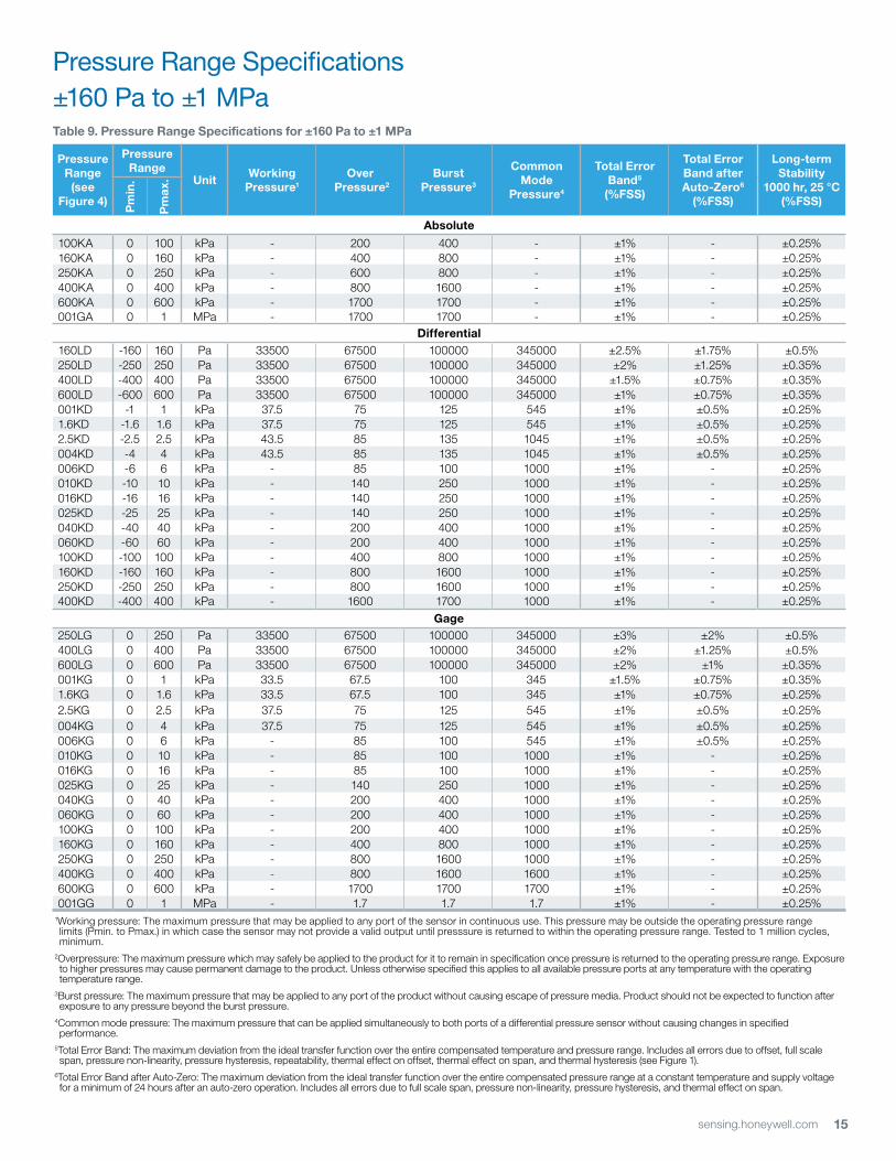
Pressure Range Specifications±160 Pa to ±1 MPatable 9. Pressure range Specifications for ±160 Pa to ±1 MPa
Pressure range
(see figure 4)
Pressure range
Unitworking
Pressure1over
Pressure2Burst
Pressure3
Common Mode
Pressure4
total error Band5
(%fSS)
total error Band after Auto-zero6
(%fSS)
long-term Stability
1000 hr, 25 °C(%fSS)
Pm
in.
Pm
ax.
Absolute
100KA 0 100 kPa - 200 400 - ±1% - ±0.25%160KA 0 160 kPa - 400 800 - ±1% - ±0.25%250KA 0 250 kPa - 600 800 - ±1% - ±0.25%400KA 0 400 kPa - 800 1600 - ±1% - ±0.25%600KA 0 600 kPa - 1700 1700 - ±1% - ±0.25%001GA 0 1 MPa - 1700 1700 - ±1% - ±0.25%
Differential160LD -160 160 Pa 33500 67500 100000 345000 ±2.5% ±1.75% ±0.5%250LD -250 250 Pa 33500 67500 100000 345000 ±2% ±1.25% ±0.35%400LD -400 400 Pa 33500 67500 100000 345000 ±1.5% ±0.75% ±0.35%600LD -600 600 Pa 33500 67500 100000 345000 ±1% ±0.75% ±0.35%001KD -1 1 kPa 37.5 75 125 545 ±1% ±0.5% ±0.25%1.6KD -1.6 1.6 kPa 37.5 75 125 545 ±1% ±0.5% ±0.25%2.5KD -2.5 2.5 kPa 43.5 85 135 1045 ±1% ±0.5% ±0.25%004KD -4 4 kPa 43.5 85 135 1045 ±1% ±0.5% ±0.25%006KD -6 6 kPa - 85 100 1000 ±1% - ±0.25%010KD -10 10 kPa - 140 250 1000 ±1% - ±0.25%016KD -16 16 kPa - 140 250 1000 ±1% - ±0.25%025KD -25 25 kPa - 140 250 1000 ±1% - ±0.25%040KD -40 40 kPa - 200 400 1000 ±1% - ±0.25%060KD -60 60 kPa - 200 400 1000 ±1% - ±0.25%100KD -100 100 kPa - 400 800 1000 ±1% - ±0.25%160KD -160 160 kPa - 800 1600 1000 ±1% - ±0.25%250KD -250 250 kPa - 800 1600 1000 ±1% - ±0.25%400KD -400 400 kPa - 1600 1700 1000 ±1% - ±0.25%
gage250LG 0 250 Pa 33500 67500 100000 345000 ±3% ±2% ±0.5%400LG 0 400 Pa 33500 67500 100000 345000 ±2% ±1.25% ±0.5%600LG 0 600 Pa 33500 67500 100000 345000 ±2% ±1% ±0.35%001KG 0 1 kPa 33.5 67.5 100 345 ±1.5% ±0.75% ±0.35%1.6KG 0 1.6 kPa 33.5 67.5 100 345 ±1% ±0.75% ±0.25%2.5KG 0 2.5 kPa 37.5 75 125 545 ±1% ±0.5% ±0.25%004KG 0 4 kPa 37.5 75 125 545 ±1% ±0.5% ±0.25%006KG 0 6 kPa - 85 100 545 ±1% ±0.5% ±0.25%010KG 0 10 kPa - 85 100 1000 ±1% - ±0.25%016KG 0 16 kPa - 85 100 1000 ±1% - ±0.25%025KG 0 25 kPa - 140 250 1000 ±1% - ±0.25%040KG 0 40 kPa - 200 400 1000 ±1% - ±0.25%060KG 0 60 kPa - 200 400 1000 ±1% - ±0.25%100KG 0 100 kPa - 200 400 1000 ±1% - ±0.25%160KG 0 160 kPa - 400 800 1000 ±1% - ±0.25%250KG 0 250 kPa - 800 1600 1000 ±1% - ±0.25%400KG 0 400 kPa - 800 1600 1600 ±1% - ±0.25%600KG 0 600 kPa - 1700 1700 1700 ±1% - ±0.25%001GG 0 1 MPa - 1.7 1.7 1.7 ±1% - ±0.25%
1Working pressure: The maximum pressure that may be applied to any port of the sensor in continuous use. This pressure may be outside the operating pressure range limits (Pmin. to Pmax.) in which case the sensor may not provide a valid output until presssure is returned to within the operating pressure range. Tested to 1 million cycles, minimum.
2Overpressure: The maximum pressure which may safely be applied to the product for it to remain in specification once pressure is returned to the operating pressure range. Exposure to higher pressures may cause permanent damage to the product. Unless otherwise specified this applies to all available pressure ports at any temperature with the operating temperature range.
3Burst pressure: The maximum pressure that may be applied to any port of the product without causing escape of pressure media. Product should not be expected to function after exposure to any pressure beyond the burst pressure.
4Common mode pressure: The maximum pressure that can be applied simultaneously to both ports of a differential pressure sensor without causing changes in specified performance.
5Total Error Band: The maximum deviation from the ideal transfer function over the entire compensated temperature and pressure range. Includes all errors due to offset, full scale span, pressure non-linearity, pressure hysteresis, repeatability, thermal effect on offset, thermal effect on span, and thermal hysteresis (see Figure 1).
6Total Error Band after Auto-Zero: The maximum deviation from the ideal transfer function over the entire compensated pressure range at a constant temperature and supply voltage for a minimum of 24 hours after an auto-zero operation. Includes all errors due to full scale span, pressure non-linearity, pressure hysteresis, and thermal effect on span.
16 sensing.honeywell.com
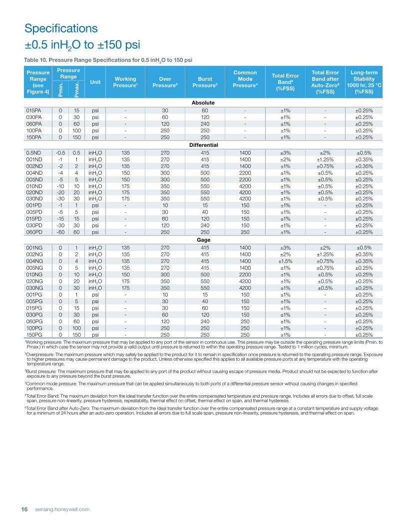
Specifications±0.5 inH2O to ±150 psitable 10. Pressure range Specifications for 0.5 inH2o to 150 psi
Pressure range
(see figure 4)
Pressure range
Unitworking
Pressure1over
Pressure2Burst
Pressure3
Common Mode
Pressure4
total error Band5
(%fSS)
total error Band after Auto-zero6
(%fSS)
long-term Stability
1000 hr, 25 °C(%fSS)
Pm
in.
Pm
ax.
Absolute015PA 0 15 psi - 30 60 - ±1% - ±0.25%030PA 0 30 psi - 60 120 - ±1% - ±0.25%060PA 0 60 psi - 120 240 - ±1% - ±0.25%100PA 0 100 psi - 250 250 - ±1% - ±0.25%150PA 0 150 psi - 250 250 - ±1% - ±0.25%
Differential0.5ND -0.5 0.5 inH2O 135 270 415 1400 ±3% ±2% ±0.5%001ND -1 1 inH2O 135 270 415 1400 ±2% ±1.25% ±0.35%002ND -2 2 inH2O 135 270 415 1400 ±1% ±0.75% ±0.35%004ND -4 4 inH2O 150 300 500 2200 ±1% ±0.5% ±0.25%005ND -5 5 inH2O 150 300 500 2200 ±1% ±0.5% ±0.25%010ND -10 10 inH2O 175 350 550 4200 ±1% ±0.5% ±0.25%020ND -20 20 inH2O 175 350 550 4200 ±1% ±0.5% ±0.25%030ND -30 30 inH2O 175 350 550 4200 ±1% ±0.5% ±0.25%001PD -1 1 psi - 10 15 150 ±1% - ±0.25%005PD -5 5 psi - 30 40 150 ±1% - ±0.25%015PD -15 15 psi - 60 120 150 ±1% - ±0.25%030PD -30 30 psi - 120 240 150 ±1% - ±0.25%060PD -60 60 psi - 250 250 250 ±1% - ±0.25%
gage001NG 0 1 inH2O 135 270 415 1400 ±3% ±2% ±0.5%002NG 0 2 inH2O 135 270 415 1400 ±2% ±1.25% ±0.35%004NG 0 4 inH2O 135 270 415 1400 ±1.5% ±0.75% ±0.35%005NG 0 5 inH2O 135 270 415 1400 ±1% ±0.75% ±0.25%010NG 0 10 inH2O 150 300 500 2200 ±1% ±0.5% ±0.25%020NG 0 20 inH2O 175 350 550 4200 ±1% ±0.5% ±0.25%030NG 0 30 inH2O 175 350 550 4200 ±1% ±0.5% ±0.25%001PG 0 1 psi - 10 15 150 ±1% - ±0.25%005PG 0 5 psi - 30 40 150 ±1% - ±0.25%015PG 0 15 psi - 30 60 150 ±1% - ±0.25%030PG 0 30 psi - 60 120 150 ±1% - ±0.25%060PG 0 60 psi - 120 240 250 ±1% - ±0.25%100PG 0 100 psi - 250 250 250 ±1% - ±0.25%150PG 0 150 psi - 250 250 250 ±1% - ±0.25%
1Working pressure: The maximum pressure that may be applied to any port of the sensor in continuous use. This pressure may be outside the operating pressure range limits (Pmin. to Pmax.) in which case the sensor may not provide a valid output until pressure is returned to within the operating pressure range. Tested to 1 million cycles, minimum.
2Overpressure: The maximum pressure which may safely be applied to the product for it to remain in specification once pressure is returned to the operating pressure range. Exposure to higher pressures may cause permanent damage to the product. Unless otherwise specified this applies to all available pressure ports at any temperature with the operating temperature range.
3Burst pressure: The maximum pressure that may be applied to any port of the product without causing escape of pressure media. Product should not be expected to function after exposure to any pressure beyond the burst pressure.
4Common mode pressure: The maximum pressure that can be applied simultaneously to both ports of a differential pressure sensor without causing changes in specified performance.
5Total Error Band: The maximum deviation from the ideal transfer function over the entire compensated temperature and pressure range. Includes all errors due to offset, full scale span, pressure non-linearity, pressure hysteresis, repeatability, thermal effect on offset, thermal effect on span, and thermal hysteresis
6Total Error Band after Auto-Zero: The maximum deviation from the ideal transfer function over the entire compensated pressure range at a constant temperature and supply voltage for a minimum of 24 hours after an auto-zero operation. Includes all errors due to full scale span, pressure non-linearity, pressure hysteresis, and thermal effect on span.
17sensing.honeywell.com
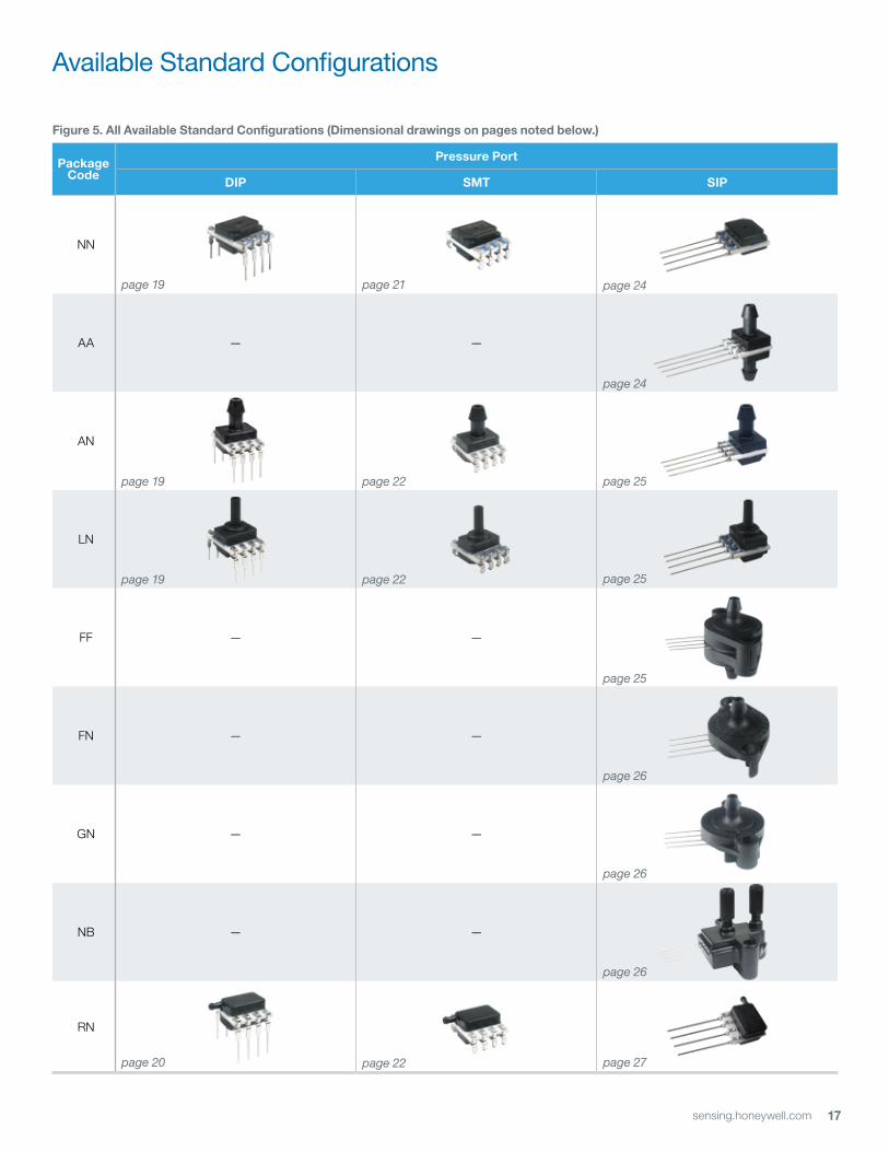
figure 5. All Available Standard Configurations (Dimensional drawings on pages noted below.)
PackageCode
Pressure Port
DiP SMt SiP
NN
AA — —
AN
LN
FF — —
FN — —
GN — —
NB — —
RN
page 19 page 21 page 24
page 24
page 19 page 22 page 25
page 19 page 22 page 25
page 20 page 22 page 27
page 26
page 26
page 26
page 25
Available Standard Configurations
18 sensing.honeywell.com
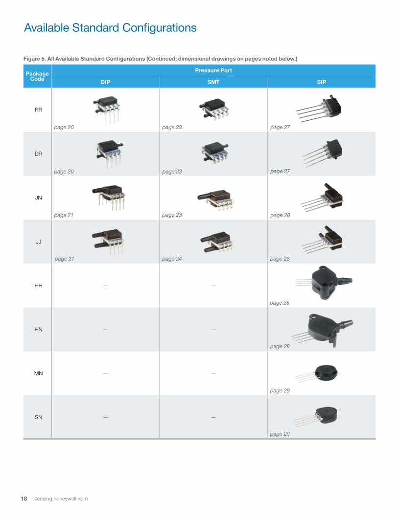
figure 5. All Available Standard Configurations (Continued; dimensional drawings on pages noted below.)
PackageCode
Pressure Port
DiP SMt SiP
RR
DR
JN — —
JJ
HH — —
HN — —
MN — —
SN — —
page 20 page 23 page 27
page 23 page 27
page 28
page 21 page 24
page 28
page 21 page 23
page 28
page 29
page 29
page 29
page 20
Available Standard Configurations
19sensing.honeywell.com
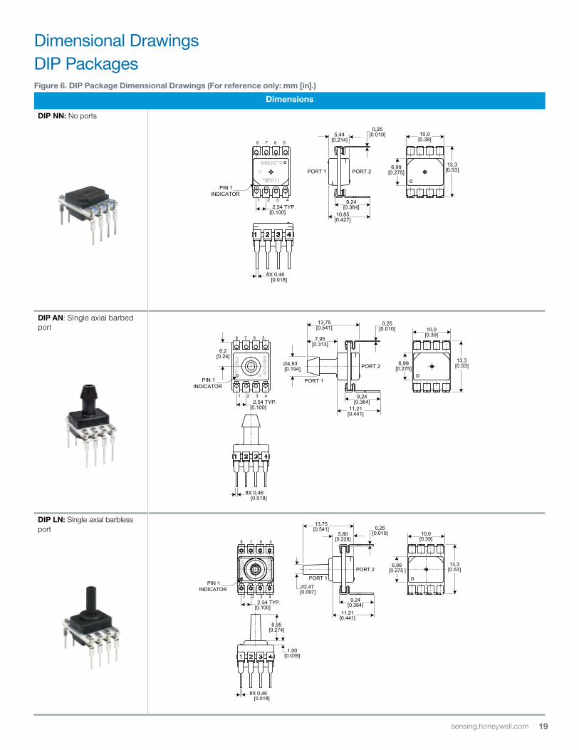
figure 6. DiP Package Dimensional Drawings (for reference only: mm [in].)
Dimensions
DiP nn: No ports
DIP AN: SIngle axial barbed port
DiP ln: Single axial barbless port
1 2 3 4
10,0[0.39]
PORT 1
8 7 6 5
6,2[0.24]
2,54 TYP.[0.100]
9,24[0.364]
11,21[0.441]
7,95[0.313]
13,75[0.541]
4,93 [0.194] PORT 2 6,99
[0.275]
8X 0,46 [0.018]
0,25[0.010]
13,3[0.53]
PIN 1INDICATOR
PORT 1
PORT 2
10,0[0.39]
6,99[0.275 ]
2,54 TYP.[0.100]
6,95[0.274]
1,00[0.039]
9,24[0.364]
11,21[0.441]
13,75[0.541]
5,80[0.228]
1 2 3 4
8 7 6 5
8X 0,46 [0.018]
0,25[0.010]
2,47 [0.097]
13,3[0.53]
PIN 1INDICATOR
10,0[0.39]
6,99[0.275]
1 2 3 4
8 7 6 5
10,85[0.427]
9,24[0.364]
5,44[0.214]
2,54 TYP.[0.100]
8X 0,46 [0.018]
0,25[0.010]
PORT 1 PORT 213,3
[0.53]
PIN 1INDICATOR
Dimensional DrawingsDIP Packages
20 sensing.honeywell.com
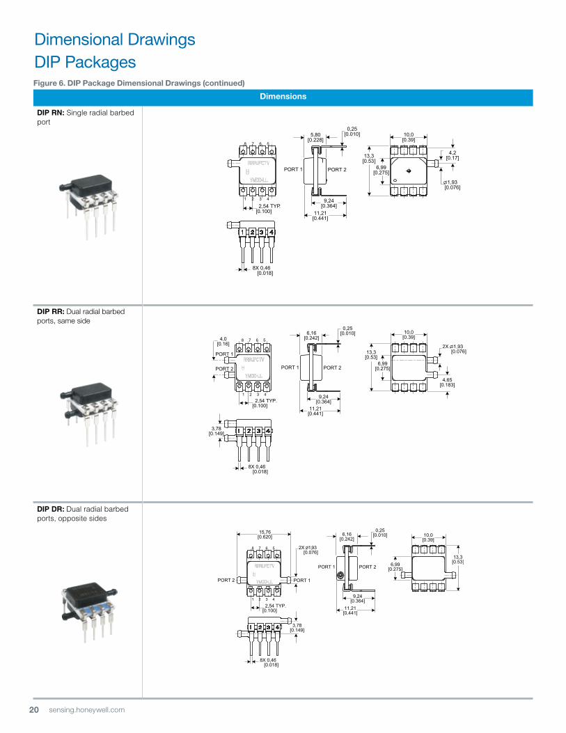
figure 6. DiP Package Dimensional Drawings (continued)
Dimensions
DIP RN: Single radial barbed port
DiP rr: Dual radial barbed ports, same side
DIP DR: Dual radial barbed ports, opposite sides
10,0[0.39]
PORT 1
1 2 3 4
8 7 6 5
6,16[0.242]
9,24[0.364]
2,54 TYP.[0.100]
15,76[0.620]
11,21[0.441]
2X 1,93 [0.076]
6,99[0.275]
8X 0,46 [0.018]
0,25[0.010]
PORT 1 PORT 2
3,78[0.149]
13,3[0.53]
PORT 2
PORT 1
13,3[0.53]
10,0[0.39]
6,99[0.275]
1 2 3 4
8 7 6 5
11,21[0.441]
9,24[0.364]
5,80[0.228]
2,54 TYP.[0.100]
8X 0,46 [0.018]
0,25[0.010]
1,93 [0.076]
4,2[0.17]
PORT 2
8X 0,46 [0.018]
13,3[0.53]
10,0[0.39]
6,99[0.275]
1 2 3 4
8 7 6 5
6,16[0.242]
2,54 TYP.[0.100] 11,21
[0.441]
9,24[0.364]
2X 1,93 [0.076]
4,65[0.183]
,25[0.010]
PORT 1 PORT 2
PORT 1
PORT 2
4,0[0.16]
3,78[0.149]
0
Dimensional DrawingsDIP Packages
21sensing.honeywell.com
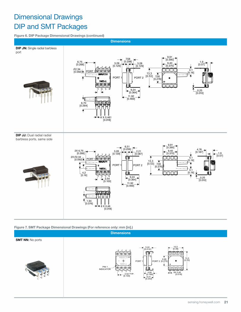
figure 6. DiP Package Dimensional Drawings (continued)
Dimensions
DiP Jn: Single radial barbless port
DIP JJ: Dual radial radial barbless ports, same side
1 2 3 4
8 X 0,46 [0.018]
11,92[0.469]
9,24[0.364]
2X 6,75 [0.266]
PORT 1
6,51[0.256] 4,76
[0.187] 1,9[0.07]
PORT 1
PORT 2
1,94[0.076]
8 7 6 5
2,54[0.100]
3,28[0.129]
2,21[0.087]
4,1[0.16]
4,1[0.16]
4,2[0.16]
9,91[0.390]
9,40[0.370]
2X 2,34 [0.092]
0,25[0.010]
7,00[0.276]
13,3[0.53]
1 2 3 4
8 X 0,461 [0.018]
11,92[0.469]
9,24[0.364]
2,34 [0.092]
6,75 [0.266]
PORT 1
7,58[0.298] 1,9
[0.07]
PORT 1
PORT 2
6,70[0.264]
8 7 6 5
3,28[0.129]
3,28[0.129]
7,00[0.276]
4,1[0.16]
9,91[0.390]
9,40[0.370]
0,25[0.010]
13,3[0.53]
figure 7. SMt Package Dimensional Drawings (for reference only: mm [in].)
Dimensions
SMt nn: No ports
13,3[0.53]
10,0[0.39]
6,99[0.275]
1 2 3 4
8 7 6 5
5,44[0.214]
2,54 TYP.[0.100] 6,41
[0.252]
4,80[0.189]
8X 0,46 [0.018]
PORT 1 PORT 2
PIN 1INDICATOR
Dimensional DrawingsDIP and SMT Packages
22 sensing.honeywell.com
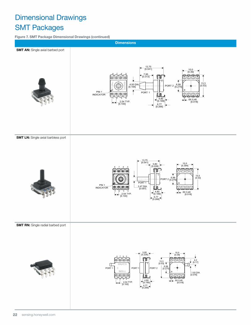
figure 7. SMt Package Dimensional Drawings (continued)
Dimensions
SMt An: Single axial barbed port
SMt ln: Single axial barbless port
SMt rn: Single radial barbed port
13,3[0.53]
10,0[0.39]
6,99[0.275]
1 2 3 4
8 7 6 5
5,80[0.228]
2,54 TYP.[0.100] 6,77
[0.266]
4,80[0.189]
8X 0,46 [0.018]
PORT 1
1,93 DIA. [0.076]
4,2[0.17]
PORT 1 PORT 2
10,0[0.394]
6,99[0.275]
1 2 3 4
8 7 6 5
2,54 TYP.[0.100] 6,77
[0.266]
4,80[0.189]
5,80[0.228]
13,75[0.541]
8X 0,46 [0.018]
PORT 1PORT 2
2,47 DIA.[0.097]
13,3 [0.53]
PIN 1INDICATOR
1 2 3 4
8 7 6 5
10,0[0.39]
7,95[0.313]
13,75[0.541]
4,93 DIA.[0.194]
2,54 TYP.[0.100]
PORT
2PORT
1
6,77[0.266]
4,80[0.189] 8X 0,46
[0.018]
6,99[0.275]
13,3[0.53]
PIN 1INDICATOR
Dimensional DrawingsSMT Packages
23sensing.honeywell.com
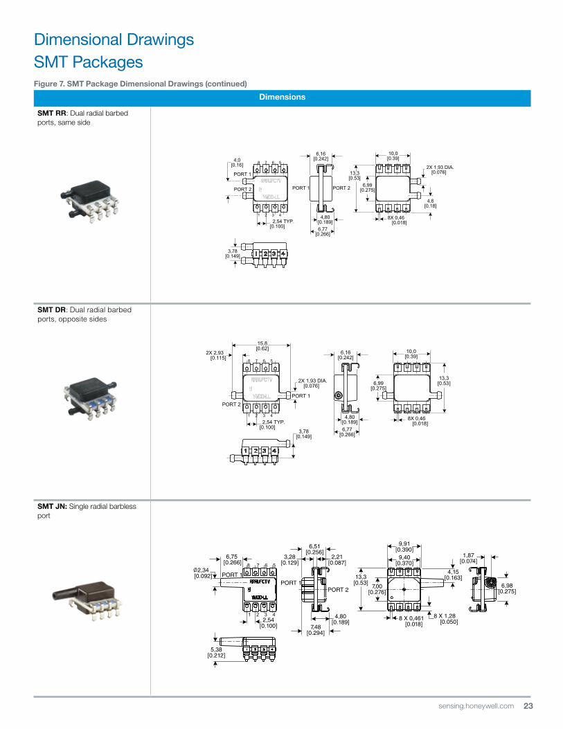
figure 7. SMt Package Dimensional Drawings (continued)
Dimensions
SMt rr: Dual radial barbed ports, same side
SMT DR: Dual radial barbed ports, opposite sides
SMt Jn: Single radial barbless port
1 2 3 4
8 7 6 5
PORT 1PORT 2
10,0[0.39]
6,99[0.275]
2X 2,93 [0.115]
15,8[0.62]
2,54 TYP.[0.100]
2X 1,93 DIA.[0.076]
6,77[0.266]
4,80[0.189]
6,16[0.242]
3,78[0.149]
8X 0,46 [0.018]
13,3[0.53]
10,0[0.39]
6,99[0.275]
1 2 3 4
8 7 6 5
6,16[0.242]
2,54 TYP.[0.100] 6,77
[0.266]
4,80[0.189]
8X 0,46 [0.018]
13,3[0.53]
4,6[0.18]
PORT 1
PORT 2
2X 1,93 DIA. [0.076]
PORT 1 PORT 2
4,0[0.16]
3,78[0.149]
1 2 3 4 8 X 0,461 [0.018]7,48
[0.294]
4,80[0.189]
2,34 [0.092] 13,3
[0.53]
6,75 [0.266]
PORT 1
6,51[0.256]
9,91[0.390]
1,87[0.074]
PORT 1
PORT 2
5,38[0.212]
8 7 6 59,40
[0.370]3,28
[0.129]2,21
[0.087]
7,00[0.276]
4,15[0.163]
2,54[0.100]
8 X 1,28 [0.050]
6,98[0.275]
Dimensional DrawingsSMT Packages

24 sensing.honeywell.com
figure 8. SiP Package Dimensional Drawings (for reference only: mm [in].)
Dimensions
SiP nn: No ports
SIP AA: Dual axial barbed ports, opposite sides
figure 7. SMt Package Dimensional Drawings (continued)
Dimensions
SMT JJ: Dual radial barbless ports, same side
PORT 1 PORT 2
0,25[0.010]
10,0[0.39]
10,0[0.39]
2,54 TYP.[0.100]
15,2[0.60]
22,06[0.869]
2X 4.93 DIA.[0.194]
4X 0,51 [0.020]
2,54 TYP.[0.100]
10,0[0.39]
15,2[0.60]
10,0[0.39]
1 2 3 4
4X 0,51 [0.020]
4,87[0.192]
PORT 1 PORT 2
0,25[0.010]
1 2 3 4 8 X 0,461 [0.018]8,36
[0.329]
5,68[0.189]
2X 2,34 [0.092]
2X 6,75 [0.266]
PORT 1
7,58[0.298] 4,76
[0.187]
PORT 1
5,38[0.212]
8 7 6 53,28
[0.129]
7,00[0.276]
4,15[0.163]
2,54[0.100]
8 X 1,28 [0.050]
6,98[0.275]
PORT 2
4,162[0.1639]
9,91[0.390]
9,40[0.370]
13,3[0.53]
Dimensional DrawingsSMT and SIP Packages
25sensing.honeywell.com
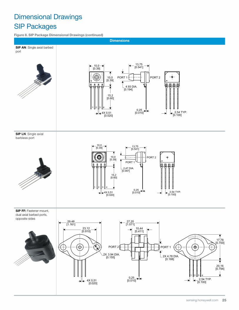
figure 8. SiP Package Dimensional Drawings (continued)
Dimensions
SiP An: Single axial barbed port
SIP LN: Single axial barbless port
SiP ff: Fastener mount, dual axial barbed ports, opposite sides
10,0[0.39]
15,2[0.60]
10,0[0.39]
1 2 3 4
2,54 TYP.[0.100]
PORT 1
PORT 2
0,25[0.010]
13,75[0.541]
4X 0,51 [0.020]
2,47 DIA.[0.097]
0,25[0.010] 2,54 TYP.
[0.100]
PORT 110,0[0.39]
4.93 DIA.[0.194]
10,0[0.39]
13,75[0.541]
15,2[0.60]
PORT 2
4X 0,51 [0.020]
0,25[0.010]
27,20[1.071]
10,44[0.411]
PORT 1PORT 2
2X 4,78 DIA.[0.188][
29,48[1.161]
23,12[0.910]
2X 3.94 DIA.0.155]
4X 0,51 [0.020]
2,54 TYP.[0.100]
17,78[0.700]
20,16[0.794]
Dimensional DrawingsSIP Packages
26 sensing.honeywell.com
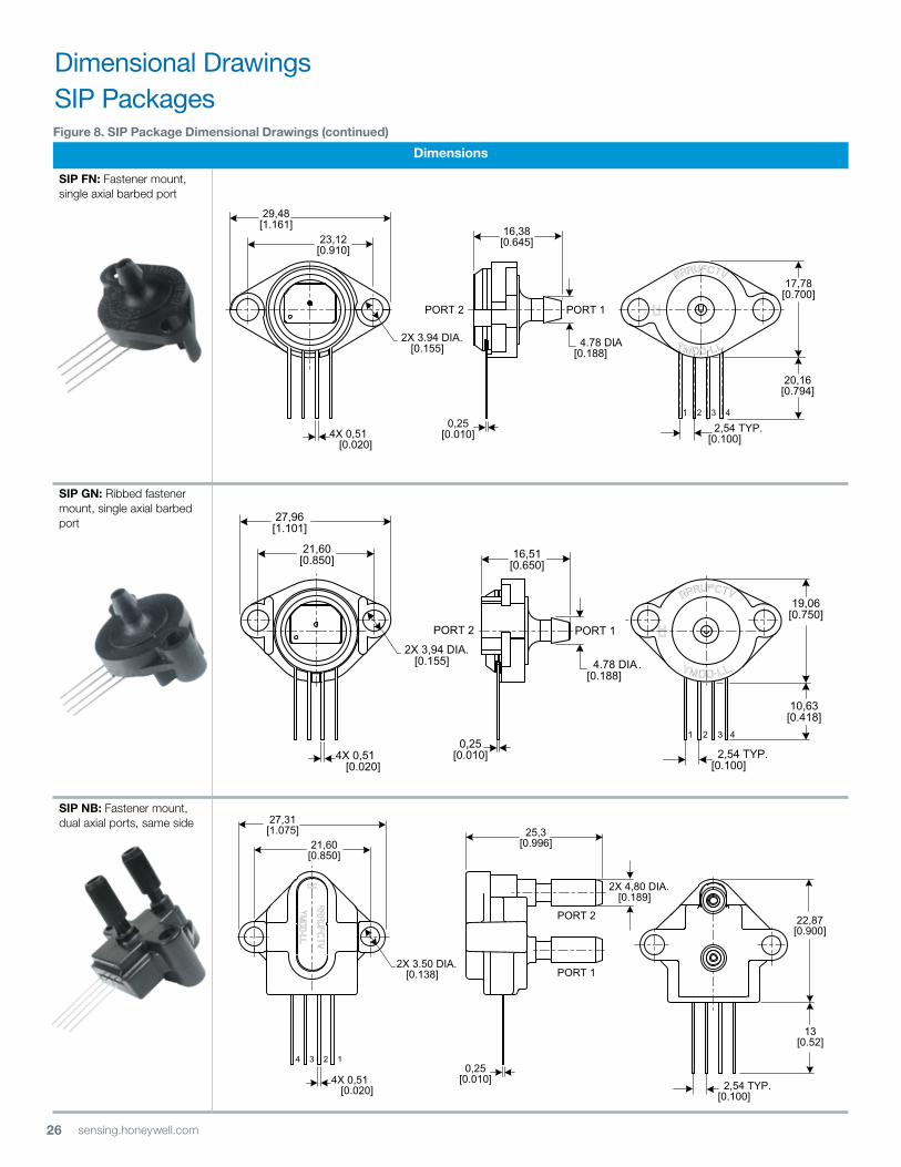
figure 8. SiP Package Dimensional Drawings (continued)
Dimensions
SiP fn: Fastener mount, single axial barbed port
SiP gn: Ribbed fastener mount, single axial barbed port
SiP nB: Fastener mount, dual axial ports, same side
17,78[0.700]
20,16[0.794]
2,54 TYP.[0.100]
0,25[0.010]
29,48[1.161]
23,12[0.910]
16,38[0.645]
2X 3.94 DIA.[0.155] 4.78 DIA.
[0.188]
4X 0,51 [0.020]
2,54 TYP.[0.100]
21,60[0.850]
PORT 1PORT 2
4.78 DIA.[0.188]
0,25[0.010]
2X 3,94 DIA.[0.155]
27,96[1.101]
16,51[0.650]
19,06[0.750]
10,63[0.418]
4X 0,51 [0.020]
0,25[0.010] 2,54 TYP.
[0.100]
22,87[0.900]
13[0.52]
2X 3.50 DIA.[0.138]
21,60[0.850]
27,31[1.075] 25,3
[0.996]
PORT 1
PORT 2
4X 0,51 [0.020]
2X 4,80 DIA.[0.189]
Dimensional DrawingsSIP Packages

27sensing.honeywell.com
figure 8. SiP Package Dimensional Drawings (continued)
Dimensions
SIP RN: Single radial barbed port
SIP RR: Dual radial barbed ports, same side
SIP DR: Dual radial barbed ports, opposite sides
0,25[0.010] 2,54 TYP.
[0.100]
PORT 1
PORT 2
10,0[0.39]
15,2[0.60]
10,0[0.39]
1 2 3 4
5,80[0.228]
1,92 DIA.[0.076]
4X 0,51 [0.020]
PORT 1
0,25[0.010] 2,54 TYP.
[0.100]
PORT 1
PORT 2
1 2 3 4
10,0[0.39]
15,2[0.60]
10,0[0.39] 2X 1,92 DIA.
[0.076]
6,16[0.243]
4X 0,51 [0.020]
PORT 1
PORT 2
0,25[0.010] 2,54 TYP.
[0.100]
PORT 1PORT 2
1 2 3 4
10,0[0.39]
10,0[0.39]
15,2[0.60]
6,16[0.243]
2X 4.93 DIA.[0.194]
15,8[0.62]
4X 0,51 [0.020]
Dimensional DrawingsSIP Packages
28 sensing.honeywell.com
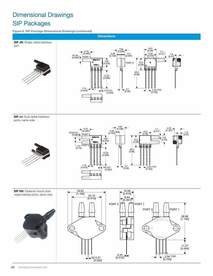
figure 8. SiP Package Dimensional Drawings (continued)
Dimensions
SIP JN: Single radial barbless port
SIP JJ: Dual radial barbless ports, same side
SIP HH: Fastener mount dual radial barbed ports, same side
1 2 3 4
4X 0,51 [0.020]
7,58[0.298]
3,28[0.129]
6,75[0.266]
4,76[0.187]
5,8[0.23]
1,7[0.07]10,0
[0.39]PORT 1
PORT 2
1,14 [0.045] 2,54 TYP.
[0.100]
1,9[0.07]
7,00[0.276]
15,20[0.598]
10,0[0.39]
25,0[0.98]
2,1 [0.08]
2X 2,34 [0.092]
4,2[0.16]
1 2 3 4
4 X 0,51 [0.020]
7,58[0.298]
3,28[0.129]
6,75[0.266]
1,7[0.07]
10,0[0.39]
PORT 1
PORT 2
1,14 [0.045] 2,54 TYP.
[0.100]
1,9[0.07]
7,00[0.276]
15,20[0.598]
10,0[0.39]
25,0[0.98]
2,1 [0.08]
2,2[0.087]
9,40[0.370] 2,34
[0.092]
0,25[0.010]
28,96[1.140]
2,54 TYP.[0.100]
PORT 1PORT 2
29,62[1.166]
23,12[0.910]
11,27[0.444]
6,64[0.261]
10,58[0.416]
4X 0,51 [0.020]
PORT 1PORT 2
Dimensional DrawingsSIP Packages
29sensing.honeywell.com
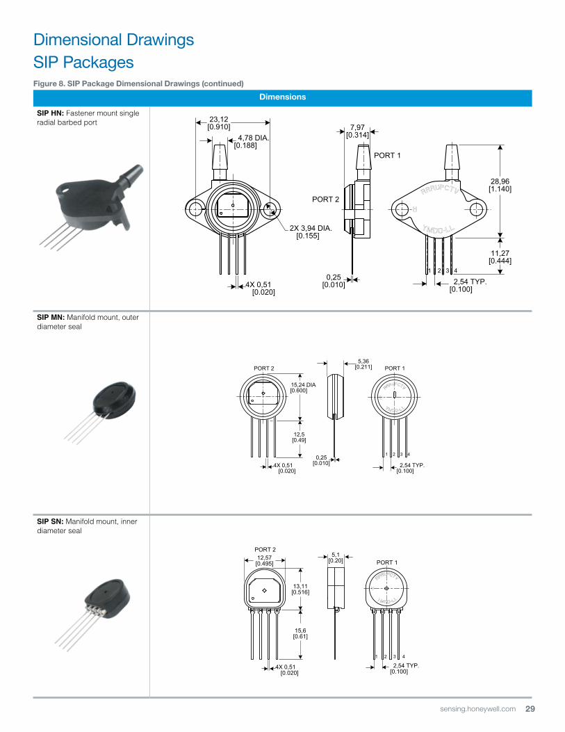
figure 8. SiP Package Dimensional Drawings (continued)
Dimensions
SIP HN: Fastener mount single radial barbed port
SIP MN: Manifold mount, outer diameter seal
SIP SN: Manifold mount, inner diameter seal
28,96[1.140]
11,27[0.444]
23,12[0.910]
0,25[0.010] 2,54 TYP.
[0.100]
2X 3,94 DIA.[0.155]
7,97[0.314] 4,78 DIA.
[0.188]
4X 0,51 [0.020]
PORT 2
2,54 TYP.[0.100]
0,25[0.010]
PORT 1PORT 2
15,24 DIA.[0.600]
12,5[0.49]
5,36[0.211]
4X 0,51 [0.020]
2,54 TYP.[0.100]
1 2 3 4
13,11[0.516]
12,57[0.495]
15,6[0.61]
5,1[0.20]
4X 0,51 [0.020]
PORT 1
PORT 2
Dimensional DrawingsSIP Packages
30 sensing.honeywell.com
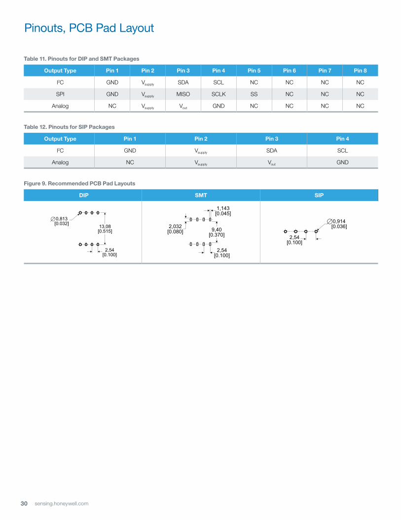
table 11. Pinouts for DiP and SMt Packages
output type Pin 1 Pin 2 Pin 3 Pin 4 Pin 5 Pin 6 Pin 7 Pin 8
I2C GND Vsupply SDA SCL NC NC NC NC
SPI GND Vsupply MISO SCLK SS NC NC NC
Analog NC Vsupply Vout GND NC NC NC NC
table 12. Pinouts for SiP Packages
output type Pin 1 Pin 2 Pin 3 Pin 4
I2C GND Vsupply SDA SCL
Analog NC Vsupply Vout GND
figure 9. recommended PCB Pad layouts
DiP SMt SiP
0,914 [0.036]
2,54[0.100]
13,08[0.515]
0,813 [0.032]
2,54[0.100]
2,54[0.100]
9,40[0.370]
2,032[0.080]
1,143[0.045]
Pinouts, PCB Pad Layout
31sensing.honeywell.com
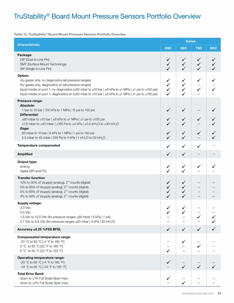
table 13. truStability® Board Mount Pressure Sensors Portfolio overview
CharacteristicSeries
HSC SSC tSC nSC
Package: DIP (Dual In-Line Pin) SMT (Surface Mount Technology) SIP (Single In-Line Pin)
option: dry gases only, no diagnostics (all pressure ranges) dry gases only, diagnostics on (all pressure ranges) liquid media on port 1, no diagnostics (±60 mbar to ±10 bar | ±6 kPa to ±1 MPa | ±1 psi to ±150 psi) liquid media on port 1, diagnostics on (±60 mbar to ±10 bar | ±6 kPa to ±1 MPa | ±1 psi to ±150 psi)
—
—
—
—
Pressure range: Absolute: 1 bar to 10 bar | 100 kPa to 1 MPa | 15 psi to 150 psi Differential: ±60 mbar to ±10 bar | ±6 kPa to ±1 MPa | ±1 psi to ±150 psi ±1.6 mbar to ±40 mbar | ±160 Pa to ±4 kPa | ±0.5 inH2O to ±30 inH2O Gage: 60 mbar to 10 bar | 6 kPa to 1 MPa | 1 psi to 150 psi 2.5 mbar to 40 mbar | 250 Pa to 4 kPa | 1 inH2O to 30 inH2O
—
—
—
temperature compensated —
Amplified — —
output type: analog digital (SPI and I2C)
—
—
transfer function: 10% to 90% of Vsupply (analog), 214 counts (digital) 5% to 95% of Vsupply (analog), 214 counts (digital) 5% to 85% of Vsupply (analog), 214 counts (digital) 4% to 94% of Vsupply (analog), 214 counts (digital)
————
————
Supply voltage: 3.3 Vdc 5.0 Vdc 1.5 Vdc to 12.0 Vdc (for pressure ranges >60 mbar | 6 kPa | 1 psi) 2.7 Vdc to 6.5 Vdc (for pressure ranges <40 mbar | 4 kPa | 20 inH2O)
——
——
——
—
——
Accuracy <0.25 %fSS BfSl Compensated temperature range: -20 °C to 85 °C [-4 °F to 185 °F] 0 °C to 85 °C [32 °F to 185 °F] 0 °C to 50 °C [32 °F to 122 °F]
——
——
—
—
———
operating temperature range: -20 °C to 85 °C [-4 °F to 185 °F] -40 °C to 85 °C [-40 °F to 185 °F]
—
—
—
—
total error Band: down to ±1% Full Scale Span max. down to ±2% Full Scale Span max.
—
—
——
——
TruStability® Board Mount Pressure Sensors Portfolio Overview
32 sensing.honeywell.com
ADDitionAl inforMAtion
The following associated literature is available at sensing.honeywell.com:
• Product line guide
• Product range guide
• Product nomenclature tree
• Installation instructions
• Application information
• Technical notes:
- I2C Communications with Honeywell Digital Output Pressure Sensors
- SPI Communications with Honeywell Digital Output Pressure Sensors
wArrAnty/reMeDy
Honeywell warrants goods of its manufacture as being free of defective materials and faulty workmanship. Honeywell’s standard product warranty applies unless agreed to otherwise by Honeywell in writing; please refer to your order acknowledgement or consult your local sales office for specific warranty details. If warranted goods are returned to Honeywell during the period of coverage, Honeywell will repair or replace, at its option, without charge those items it finds defective. the foregoing is buyer’s sole remedy and is in lieu of all other warranties, expressed or implied, including those of merchantability and fitness for a particular purpose. in no event shall Honeywell be liable for consequential, special, or indirect damages.
While we provide application assistance personally, through our literature and the Honeywell website, it is up to the customer to determine the suitability of the product in the application.
Specifications may change without notice. The information we supply is believed to be accurate and reliable as of this printing. However, we assume no responsibility for its use.
WARNINGPERSONAL INJURYDO NOT USE these products as safety or emergency stop devices or in any other application where failure of the product could result in personal injury.
Failure to comply with these instructions could result in death or serious injury.
WARNINGMISUSE OF DOCUMENTATION• The information presented in this product sheet is for
reference only. Do not use this document as a product installation guide.
• Complete installation, operation, and maintenance information is provided in the instructions supplied with each product.
Failure to comply with these instructions could result in death or serious injury.
Sales and ServiceHoneywell serves its customers through a worldwide network of sales offices, representatives and distributors. For application assistance, current specifications, pricing or name of the nearest Authorized Distributor, contact your local sales office or email us at [email protected]. Visit us on the Web at sensing.honeywell.com
Phone and Fax:Asia Pacific +65 6355-2828 +65 6445-3033 FaxEurope +44 (0) 1698 481481 +44 (0) 1698 481676 FaxLatin America +1-305-805-8188 +1-305-883-8257 FaxUSA/Canada +1-800-537-6945 +1-815-235-6847 +1-815-235-6545 Fax
Sensing and Control
Honeywell
1985 Douglas Drive North
Golden Valley, MN 55422
honeywell.com
50099148-A-EN IL50August 2014© 2014 Honeywell International Inc. All rights reserved.