troubleshooting a k40 laser power subsystem
TRANSCRIPT
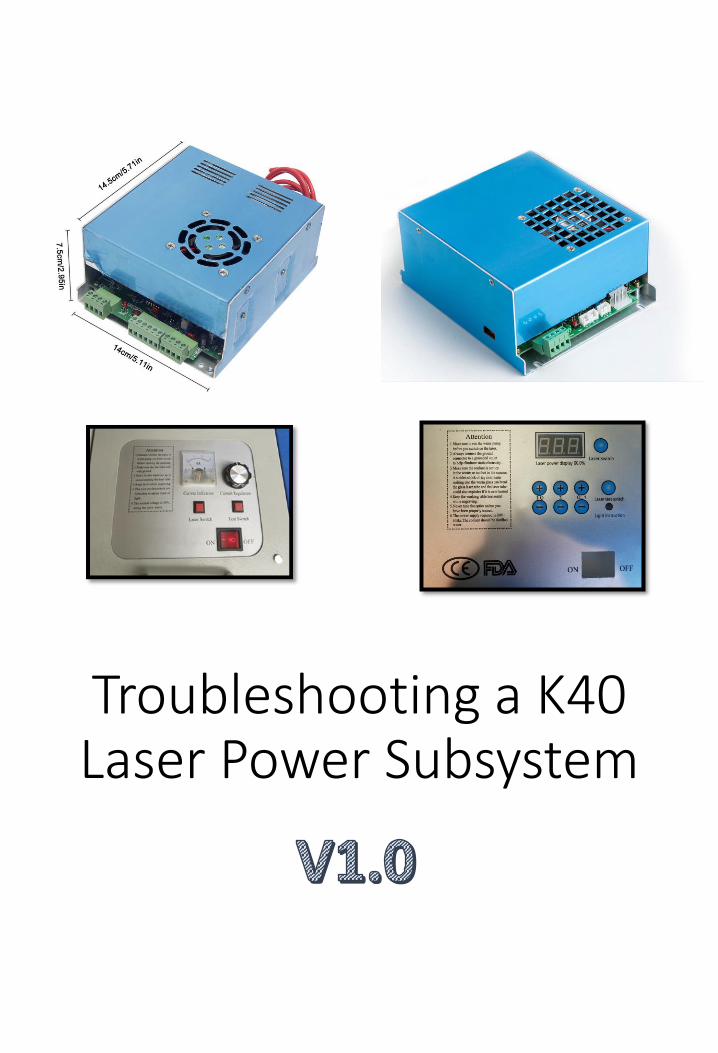
Troubleshooting a K40 Laser Power Subsystem
• The author(s) do not make any warranties about the completeness, reliability and accuracy of this information. Any action you take upon the information in this document is strictly at your own risk, and the author will not be held liable for any losses and damages in connection with the use of this information.
This work is licensed under a Creative Commons Attribution-NonCommercial 4.0 International License.
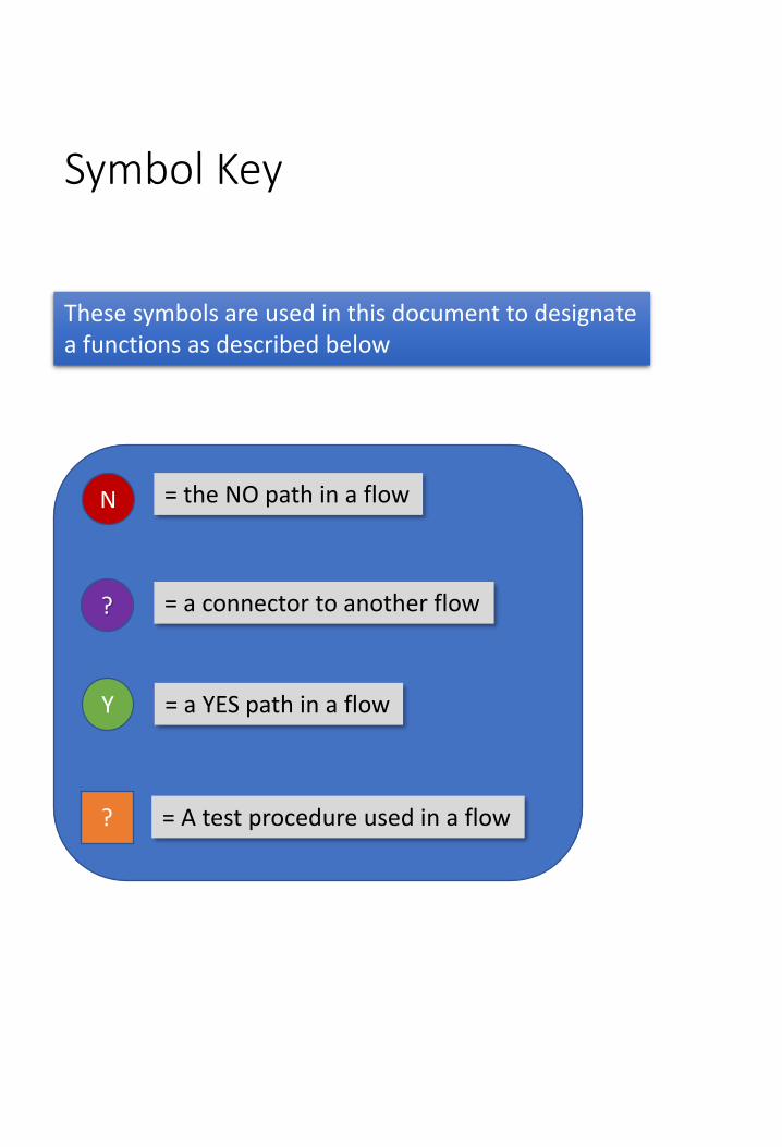
Symbol Key
?
N
?
= the NO path in a flow
= a connector to another flow
= A test procedure used in a flow
These symbols are used in this document to designate a functions as described below
Y = a YES path in a flow
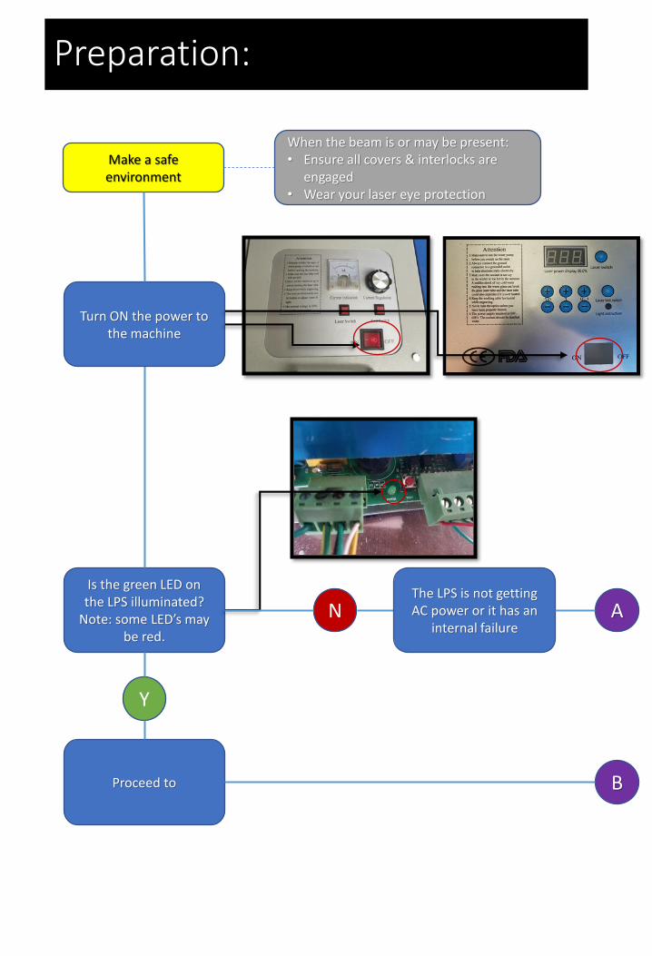
Preparation:
Make a safe environment
A
Is the green LED on the LPS illuminated?
Note: some LED’s maybe red.
Y
N
When the beam is or may be present:• Ensure all covers & interlocks are
engaged• Wear your laser eye protection
Turn ON the power to the machine
The LPS is not getting AC power or it has an
internal failure
Proceed to B
Y
N
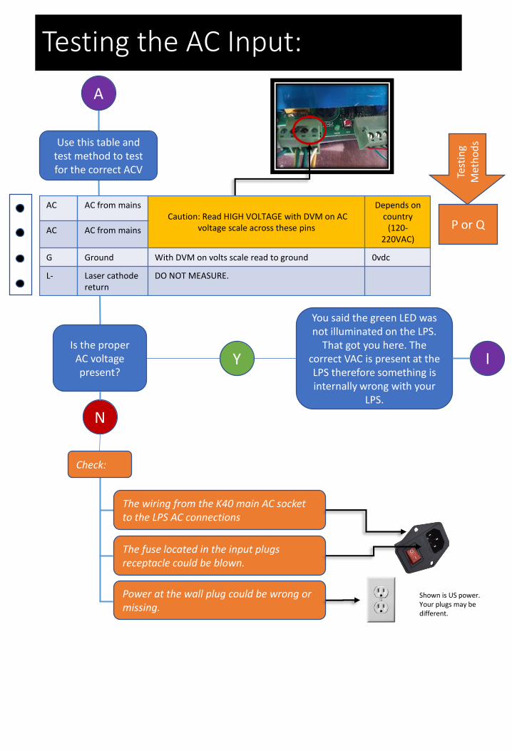
You said the green LED was not illuminated on the LPS.
That got you here. The correct VAC is present at the LPS therefore something is internally wrong with your
LPS.
The fuse located in the input plugs receptacle could be blown.
Testing the AC Input:
A
I
AC AC from mainsCaution: Read HIGH VOLTAGE with DVM on AC
voltage scale across these pins
Depends on country
(120-220VAC)
AC AC from mains
G Ground With DVM on volts scale read to ground 0vdc
L- Laser cathode return
DO NOT MEASURE.
P or Q
Test
ing
Met
ho
dsUse this table and
test method to test for the correct ACV
Is the proper AC voltage present?
The wiring from the K40 main AC socket to the LPS AC connections
Check:
Power at the wall plug could be wrong or missing.
Shown is US power. Your plugs may be different.
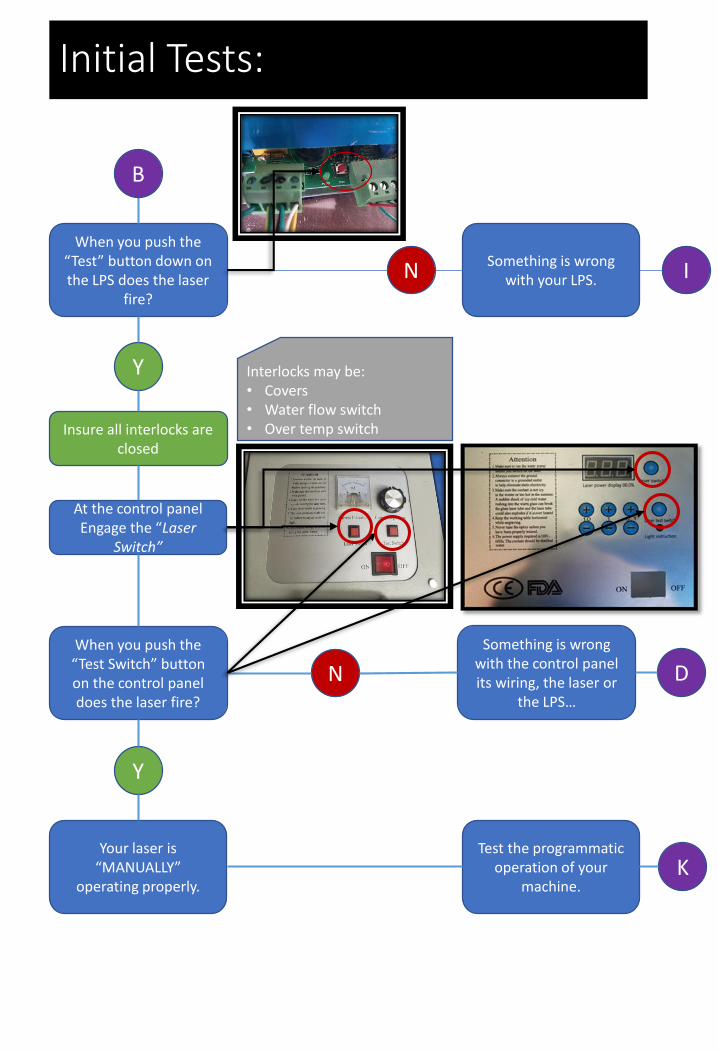
When you push the “Test” button down on the LPS does the laser
fire?
Y
NSomething is wrong
with your LPS.
When you push the “Test Switch” button on the control panel does the laser fire?
At the control panel Engage the “Laser
Switch”
Insure all interlocks are closed
Interlocks may be:• Covers • Water flow switch• Over temp switch
Initial Tests:
B
I
N
Y
Something is wrong with the control panel its wiring, the laser or
the LPS…
Your laser is “MANUALLY”
operating properly. K
Test the programmatic operation of your
machine.
D
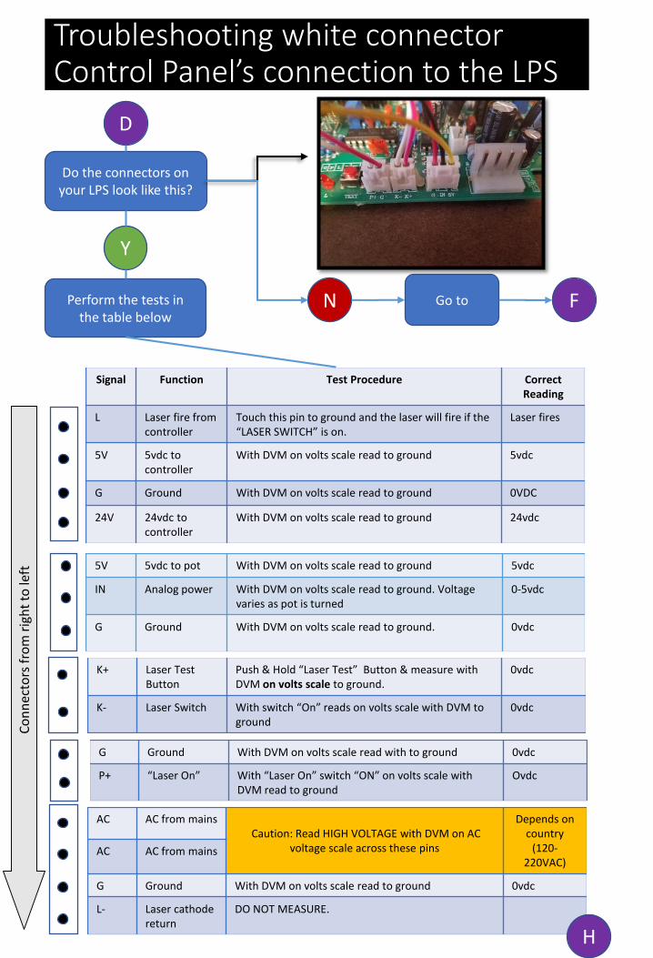
Troubleshooting white connector Control Panel’s connection to the LPS
Do the connectors on your LPS look like this?
Y
D
N FGo to
Signal Function Test Procedure Correct Reading
L Laser fire from controller
Touch this pin to ground and the laser will fire if the “LASER SWITCH” is on.
Laser fires
5V 5vdc to controller
With DVM on volts scale read to ground 5vdc
G Ground With DVM on volts scale read to ground 0VDC
24V 24vdc to controller
With DVM on volts scale read to ground 24vdc
5V 5vdc to pot With DVM on volts scale read to ground 5vdc
IN Analog power With DVM on volts scale read to ground. Voltage varies as pot is turned
0-5vdc
G Ground With DVM on volts scale read to ground. 0vdc
G Ground With DVM on volts scale read with to ground 0vdc
P+ “Laser On” With “Laser On” switch “ON” on volts scale with DVM read to ground
Ovdc
Perform the tests in the table below
AC AC from mainsCaution: Read HIGH VOLTAGE with DVM on AC
voltage scale across these pins
Depends on country
(120-220VAC)
AC AC from mains
G Ground With DVM on volts scale read to ground 0vdc
L- Laser cathode return
DO NOT MEASURE.
Co
nn
ecto
rs f
rom
rig
ht
to le
ft
K+ Laser Test Button
Push & Hold “Laser Test” Button & measure with DVM on volts scale to ground.
0vdc
K- Laser Switch With switch “On” reads on volts scale with DVM to ground
0vdc
H

Troubleshooting green connector control panel’s connection to the LPS
Do the connectors on your LPS look like this?
Y
F
N GGo to
Signal Function Test Procedure Correct Reading
L Laser fire from controller
Touch this pin to ground and the laser will fire if the “LASER SWITCH” is on.
Laser fires
5V 5vdc to controller
With DVM on volts scale read to ground 5vdc
G Ground With DVM on volts scale read to ground 0VDC
24V 24vdc to controller
With DVM on volts scale read to ground 24vdc
5V 5vdc to pot With DVM on volts scale read to ground 5vdc
IN Analog power With DVM on volts scale read to ground. Voltage varies as pot is turned
0-5vdc
G Ground With DVM on volts scale read to ground. 0vdc
L Test Switch Push & Hold “Laser Test” Switch & measure with DVM on volts scale to ground.
0vdc
P Laser Switch With switch “On” reads on volts scale with DVM to ground
0vdc
G Ground With DVM on volts scale read with to ground 0vdc
Perform the tests in the table below
AC AC from mainsCaution: Read HIGH VOLTAGE with DVM on AC
voltage scale across these pins
Depends on country
(120-220VAC)
AC AC from mains
G Ground With DVM on volts scale read to ground 0vdc
L- Laser cathode return
DO NOT MEASURE.
Co
nn
ecto
rs f
rom
rig
ht
to le
ft
HProceed to
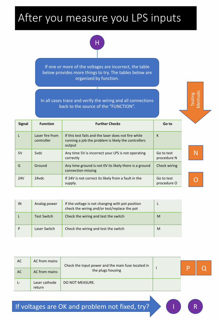
After you measure you LPS inputs
Signal Function Further Checks Go to
L Laser fire from controller
If this test fails and the laser does not fire while running a job the problem is likely the controllers output
K
5V 5vdc Any time 5V is incorrect your LPS is not operating correctly
Go to test procedure N
G Ground Any time ground is not 0V its likely there is a ground connection missing
Check wiring
24V 24vdc If 24V is not correct its likely from a fault in the supply.
Go to test procedure O
IN Analog power If the voltage is not changing with pot position check the wiring and/or test/replace the pot
L
L Test Switch Check the wiring and test the switch M
P Laser Switch Check the wiring and test the switch M
AC AC from mainsCheck the input power and the main fuse located in
the plugs housingI
AC AC from mains
L- Laser cathode return
DO NOT MEASURE.
H
If one or more of the voltages are incorrect, the table below provides more things to try. The tables below are
organized by function.
In all cases trace and verify the wiring and all connections back to the source of the “FUNCTION”.
N
O
P Q
Test
ing
Met
ho
ds
RIf voltages are OK and problem not fixed, try? I
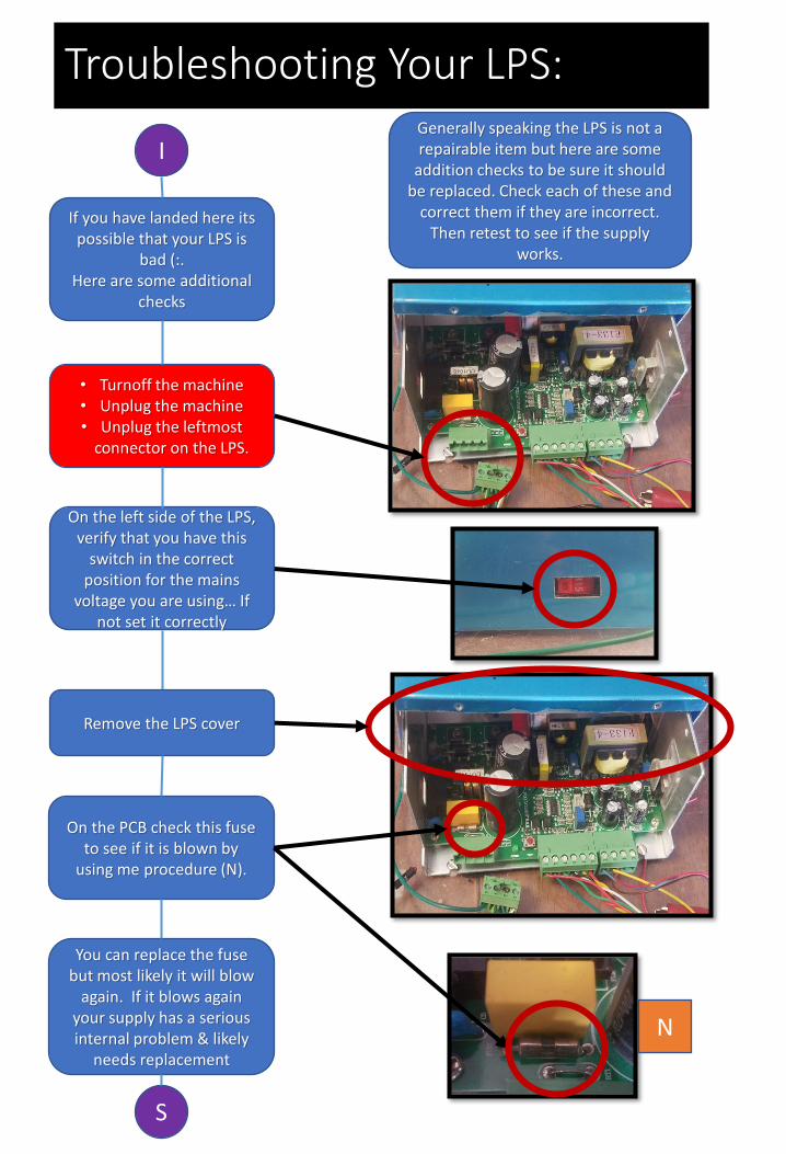
Troubleshooting Your LPS:
I
If you have landed here itspossible that your LPS is
bad (:.Here are some additional
checks
On the left side of the LPS, verify that you have this
switch in the correct position for the mains
voltage you are using… If not set it correctly
• Turnoff the machine• Unplug the machine• Unplug the leftmost
connector on the LPS.
Generally speaking the LPS is not a repairable item but here are some
addition checks to be sure it should be replaced. Check each of these and
correct them if they are incorrect. Then retest to see if the supply
works.
Remove the LPS cover
On the PCB check this fuse to see if it is blown by
using me procedure (N).
N
You can replace the fuse but most likely it will blow
again. If it blows again your supply has a serious internal problem & likely
needs replacement
S
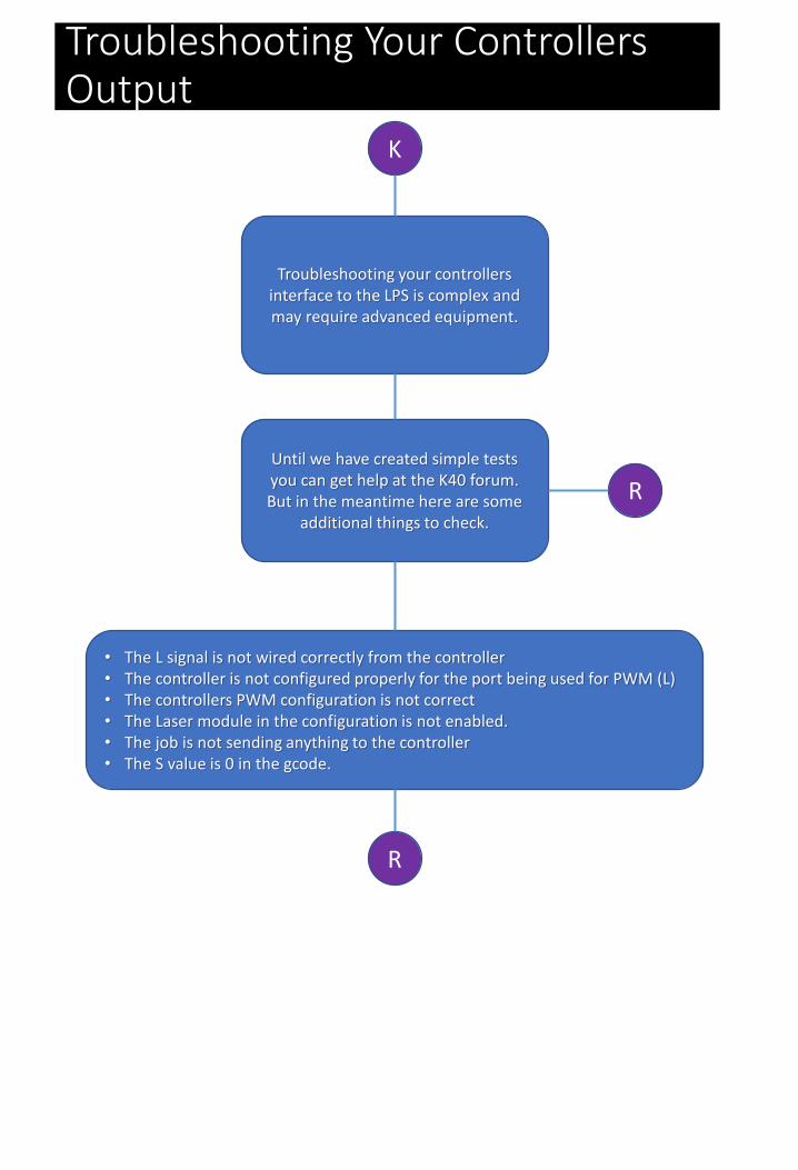
Troubleshooting Your Controllers Output
K
Troubleshooting your controllers interface to the LPS is complex and may require advanced equipment.
Until we have created simple tests you can get help at the K40 forum. But in the meantime here are some
additional things to check.
R
• The L signal is not wired correctly from the controller• The controller is not configured properly for the port being used for PWM (L)• The controllers PWM configuration is not correct• The Laser module in the configuration is not enabled.• The job is not sending anything to the controller• The S value is 0 in the gcode.
R
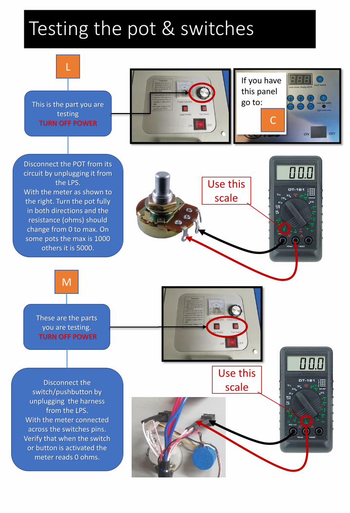
Testing the pot & switches
L
This is the part you are testing
TURN OFF POWER
Use this scale
Disconnect the POT from its circuit by unplugging it from
the LPS.With the meter as shown to the right. Turn the pot fully in both directions and the resistance (ohms) should change from 0 to max. On some pots the max is 1000
others it is 5000.
M
These are the parts you are testing.
TURN OFF POWER
Use this scaleDisconnect the
switch/pushbutton by unplugging the harness
from the LPS.With the meter connected across the switches pins.
Verify that when the switch or button is activated the
meter reads 0 ohms.
If you have this panel go to:
C
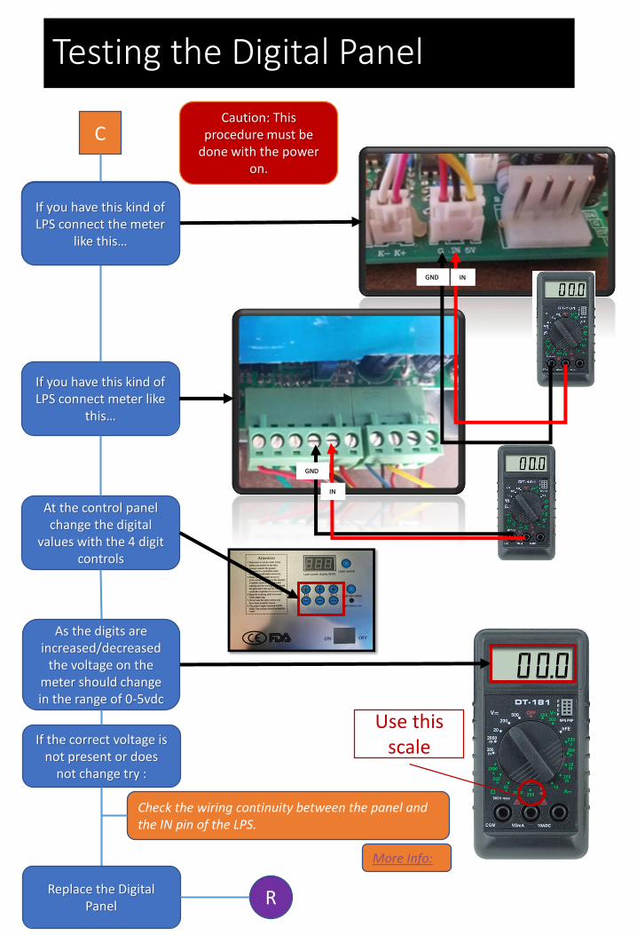
Testing the Digital Panel
C
Caution: This procedure must be
done with the power on.
If you have this kind of LPS connect meter like
this…
Use this scale
At the control panel change the digital
values with the 4 digit controls
If you have this kind of LPS connect the meter
like this…
Caution: This procedure must be
done with the power on.
As the digits areincreased/decreased
the voltage on the meter should change in the range of 0-5vdc
IN
GND
INGND
R
If the correct voltage is not present or does
not change try :
Check the wiring continuity between the panel and the IN pin of the LPS.
Replace the Digital Panel
More Info:
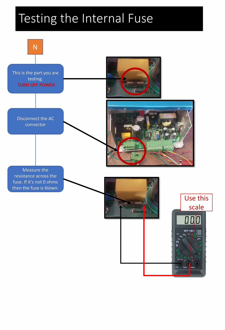
Testing the Internal Fuse
N
This is the part you are testing.
TURN OFF POWER
Disconnect the AC connector
Use this scale
Measure the resistance across the
fuse. If it's not 0 ohms then the fuse is blown.
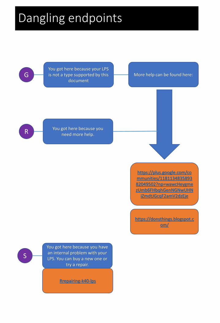
Dangling endpoints
GYou got here because your LPS is not a type supported by this
document
https://plus.google.com/communities/118113483589382049502?np=wawcHeygmezUmb6FHbqhGenNGNwUHN
iZmdtJGcqF2amV2dzEje
More help can be found here:
https://donsthings.blogspot.com/
RYou got here because you
need more help.
S
You got here because you have an internal problem with your LPS. You can buy a new one or
try a repair.
Rrepairing-k40-lps
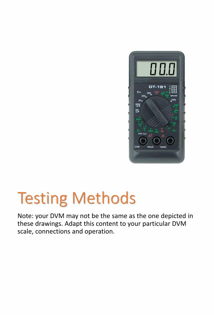
Testing MethodsNote: your DVM may not be the same as the one depicted in these drawings. Adapt this content to your particular DVM scale, connections and operation.
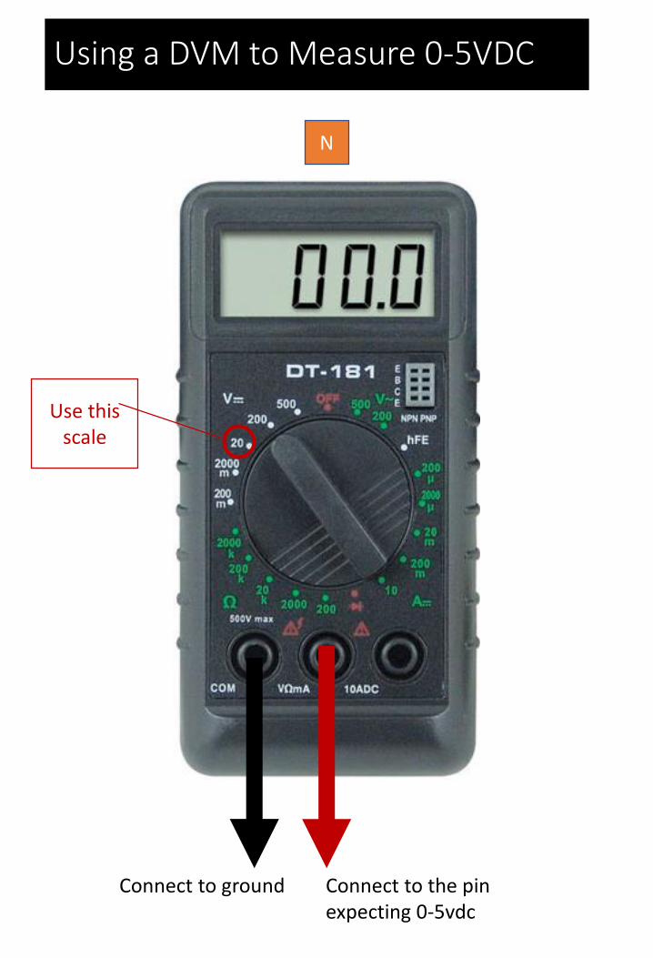
Using a DVM to Measure 0-5VDC
Connect to ground Connect to the pin expecting 0-5vdc
Use this scale
N
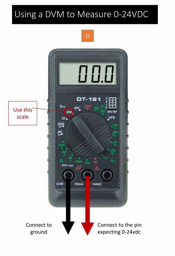
Using a DVM to Measure 0-24VDC
Connect to ground
Connect to the pin expecting 0-24vdc
Use this scale
O
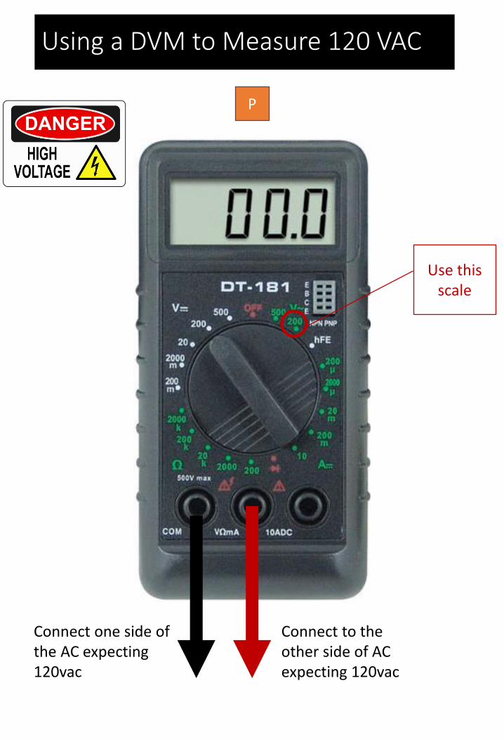
Using a DVM to Measure 120 VAC
Connect one side of the AC expecting 120vac
Connect to the other side of AC expecting 120vac
Use this scale
P

Using a DVM to Measure 220 VAC
Connect one side of the AC expecting 240VAC
Connect to the other side of AC expecting 240VAC
Use this scale
Q