triboelectric nanogenerators as a self-powered 3d ... · pdf filetriboelectric nanogenerators...
TRANSCRIPT
Triboelectric Nanogenerators as a Self-Powered 3D AccelerationSensorYao Kun Pang,† Xiao Hui Li,† Meng Xiao Chen,† Chang Bao Han,† Chi Zhang,*,†
and Zhong Lin Wang*,†,‡
†Beijing Institute of Nanoenergy and Nanosystems, Chinese Academy of Sciences, Beijing, 100083, China‡School of Material Science and Engineering, Georgia Institute of Technology, Atlanta, Georgia 30332, United States
*S Supporting Information
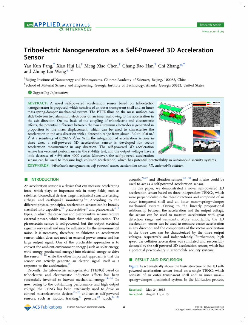
ABSTRACT: A novel self-powered acceleration sensor based on triboelectricnanogenerator is proposed, which consists of an outer transparent shell and an innermass-spring-damper mechanical system. The PTFE films on the mass surfaces canslide between two aluminum electrodes on an inner wall owing to the acceleration inthe axis direction. On the basis of the coupling of triboelectric and electrostaticeffects, the potential difference between the two aluminum electrodes is generated inproportion to the mass displacement, which can be used to characterize theacceleration in the axis direction with a detection range from about 13.0 to 40.0 m/s2 at a sensitivity of 0.289 V·s2/m. With the integration of acceleration sensors inthree axes, a self-powered 3D acceleration sensor is developed for vectoracceleration measurement in any direction. The self-powered 3D accelerationsensor has excellent performance in the stability test, and the output voltages have alittle decrease of ∼6% after 4000 cycles. Moreover, the self-powered accelerationsensor can be used to measure high collision acceleration, which has potential practicability in automobile security systems.
KEYWORDS: triboelectric nanogenerator, self-powered sensor, acceleration sensor, 3D, automobile collision
■ INTRODUCTION
An acceleration sensor is a device that can measure acceleratingforce, which plays an important role in many fields, such assatellites, biomedical devices, large mechanical structure testing,airbags, and earthquake monitoring.1,2 According to thedifferent physical principles, acceleration sensors can be broadlyclassified into capacitive,3,4 piezoresistive,5 and piezoelectric6−8
types, in which the capacitive and piezoresistive sensors requireexternal power, which may limit their wide application. Thepiezoelectric sensor is self-powered, but the output electricalsignal is very small and may be influenced by the environmentalnoise. It is necessary, therefore, to fabricate an accelerationsensor, which does not need an external power source and haslarge output signal. One of the practicable approaches is toconvert the ambient environment energy (such as solar energy,wind energy, geothermal energy) into electrical energy to drivethe sensor,9−12 while the other important approach is that thesensor can actively generate an electric signal itself as aresponse to the acceleration.13
Recently, the triboelectric nanogenerator (TENG) based ontriboelectric and electrostatic induction effects has beensuccessfully invented to harvest mechanical energy.14−16 Tonow, owing to the outstanding performance and high outputvoltage, the TENG has been extensively used to drive orcontrol microelectronic devices17−20 and act as self-poweredsensors, such as motion tracking,21 pressure,22 touch,23−25
acoustic,26,27 and vibration sensors,28−30 and it also could beused to act as a self-powered acceleration sensor.In this paper, we demonstrated a novel self-powered 3D
acceleration sensor based on three independent TENGs, whichwere perpendicular in the three directions and composed of anouter transparent shell and an inner mass−spring−dampermechanical system. Owing to the linearly proportionalrelationship between the acceleration and the output voltage,the sensor can be used to measure acceleration with greatdetection range and sensitivity. More importantly, the 3Dacceleration sensor can be used to measure vector accelerationin any direction and the components of the vector accelerationin the three axes can be characterized by the three outputvoltages, respectively and independently. Furthermore, highspeed car collision acceleration was simulated and successfullydetected by the self-powered 3D acceleration sensor, which hasa potential practicability in automobile security systems.
■ RESULT AND DISCUSSION
Figure 1a schematically shows the basic structure of the 1D self-powered acceleration sensor based on a single TENG, whichconsists of an outer transparent shell and an inner mass−spring−damper mechanical system. In the fabrication process,
Received: May 24, 2015Accepted: August 11, 2015
Research Article
www.acsami.org
© XXXX American Chemical Society A DOI: 10.1021/acsami.5b04516ACS Appl. Mater. Interfaces XXXX, XXX, XXX−XXX
the outer transparent shell was composed of acrylic sheets,which were accurately cut by a laser cutter and have the distinctadvantages of low weight, low cost, and great machinability.The cubical inertial mass is made of steel, with the side lengthof 18 mm and the weight of 28.45 g. As the fixed triboelectriclayers and electrodes, two pieces of Al films (18 mm × 40 mm)were pasted on the internal surface of the acrylic sheets, leavingan interval less than 1 mm between them. The polytetrafluoro-ethylene (PTFE) film was purposely chosen as the freestandingtriboelectric layer, which was cut into 18 mm × 18 mm andadhered on the surface of the inertial mass. In order to increasethe effective contact surface area and the surface roughness and
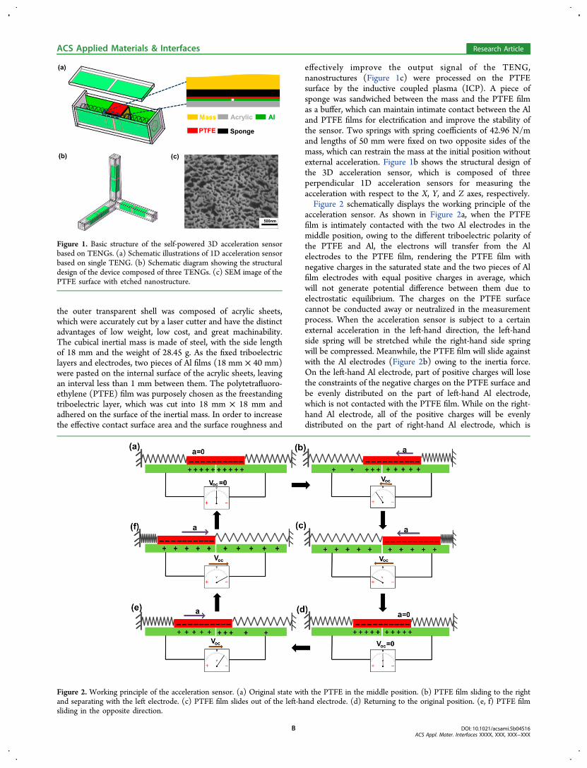
effectively improve the output signal of the TENG,nanostructures (Figure 1c) were processed on the PTFEsurface by the inductive coupled plasma (ICP). A piece ofsponge was sandwiched between the mass and the PTFE filmas a buffer, which can maintain intimate contact between the Aland PTFE films for electrification and improve the stability ofthe sensor. Two springs with spring coefficients of 42.96 N/mand lengths of 50 mm were fixed on two opposite sides of themass, which can restrain the mass at the initial position withoutexternal acceleration. Figure 1b shows the structural design ofthe 3D acceleration sensor, which is composed of threeperpendicular 1D acceleration sensors for measuring theacceleration with respect to the X, Y, and Z axes, respectively.Figure 2 schematically displays the working principle of the
acceleration sensor. As shown in Figure 2a, when the PTFEfilm is intimately contacted with the two Al electrodes in themiddle position, owing to the different triboelectric polarity ofthe PTFE and Al, the electrons will transfer from the Alelectrodes to the PTFE film, rendering the PTFE film withnegative charges in the saturated state and the two pieces of Alfilm electrodes with equal positive charges in average, whichwill not generate potential difference between them due toelectrostatic equilibrium. The charges on the PTFE surfacecannot be conducted away or neutralized in the measurementprocess. When the acceleration sensor is subject to a certainexternal acceleration in the left-hand direction, the left-handside spring will be stretched while the right-hand side springwill be compressed. Meanwhile, the PTFE film will slide againstwith the Al electrodes (Figure 2b) owing to the inertia force.On the left-hand Al electrode, part of positive charges will losethe constraints of the negative charges on the PTFE surface andbe evenly distributed on the part of left-hand Al electrode,which is not contacted with the PTFE film. While on the right-hand Al electrode, all of the positive charges will be evenlydistributed on the part of right-hand Al electrode, which is
Figure 1. Basic structure of the self-powered 3D acceleration sensorbased on TENGs. (a) Schematic illustrations of 1D acceleration sensorbased on single TENG. (b) Schematic diagram showing the structuraldesign of the device composed of three TENGs. (c) SEM image of thePTFE surface with etched nanostructure.
Figure 2. Working principle of the acceleration sensor. (a) Original state with the PTFE in the middle position. (b) PTFE film sliding to the rightand separating with the left electrode. (c) PTFE film slides out of the left-hand electrode. (d) Returning to the original position. (e, f) PTFE filmsliding in the opposite direction.
ACS Applied Materials & Interfaces Research Article
DOI: 10.1021/acsami.5b04516ACS Appl. Mater. Interfaces XXXX, XXX, XXX−XXX
B
contacted with the PTFE film. There will be a positive potentialdifference between the two electrodes. With the increasingacceleration, the mass will slide to the right-hand side until thePTFE film slides out of the left-hand electrode (Figure 2c), andall of the positive charges on the left-hand Al electrode will losethe constraints and evenly distributed on the total left-hand Alelectrode surface. While on the part of right-hand Al electrode,which is contacted with the whole PTFE film, all of the positivecharges will be evenly distributed.The potential difference willreach the maximal value. After that, if the acceleration stops, themass with the PTFE films will come back to its original positiondue to the elasticity of the springs (Figure 2d) and the potentialdifference will decrease to zero. The similar distribution ofcharges on the Al electrodes and potential difference with thereverse polarity are shown in Figures 2e and f. Therefore, thesingle TENG as a 1D self-powered acceleration sensor cancharacterize the acceleration vector in the axial direction.The relationship between the output voltages and the sliding
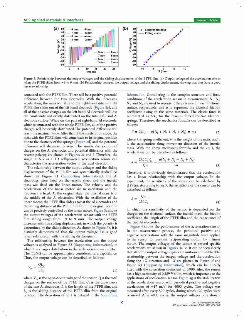
displacements of the PTFE film was systematically studied. Asshown in Figure S1 (Supporting Information), the Alelectrodes were fixed on the acrylic sheet and the inertialmass was fixed on the linear motor. The velocity and theacceleration of the linear motor are in oscillation and thefrequency is fixed. At the original state, the inertial mass is inthe middle of the Al electrodes. With the oscillation of thelinear motor, the PTFE film slides against the Al electrodes andthe sliding distance of the PTFE film from the original positioncan be precisely controlled by the linear motor. Figure 3a showsthe output voltages of the acceleration sensor with the PTFEfilm sliding range from −9 to 9 mm. The output voltageincreases with the sliding displacement, in which the polarity isdetermined by the sliding direction. As shown in Figure 3b, it isdistinctly demonstrated that the output voltage has a goodlinear relationship with the sliding displacement.The relationship between the acceleration and the output
voltage is analyzed in Figure S2 (Supporting Information), inwhich the charges distribution in the surfaces is shown in detail.The TENG can be approximately considered as a capacitance.Thus, the output voltage can be described as follows:
=VQLLC
xoc
0 (1)
where Voc is the open-circuit voltage of the sensor, Q is the totalcharges on the surface of the PTFE film, C0 is the capacitanceof the two Al electrodes, L is the length of the PTFE film, andLx is the sliding distance of the PTFE film from the originalposition. The derivation of eq 1 is detailed in the Supporting
Information. Considering to the complex structure and forceconditions of the acceleration sensor in measurement, N1, N2,N3, and N4 are used to represent the pressure for each frictionalsurface, respectively, and μ to represent the identical frictioncoefficient owing to the same materials. The elastic force isrepresented as 2kLx for the mass is forced by two identicalsprings. Therefore, the mechanics formula can be described asfollows:
μ= − + + + =F kL N N N N ma2 ( )x 1 2 3 4 (2)
where k is spring coefficient, m is the weight of the mass, and ais the acceleration along movement direction of the inertialmass. With the above mechanics formula and the eq 1, theacceleration can be described as follows:
μ= −
+ + +a
kLC VQm
N N N Nm
2 ( )oc0 1 2 3 4
(3)
Therefore, it is obviously demonstrated that the accelerationhas a linear relationship with the output voltage. In theexperiment, the sensitivity of the sensor can be calculated byΔV/Δa. According to eq 3, the sensitivity of the sensor can bedescribed as follows:
=SQmkLC2 0 (4)
in which the sensitivity of the sensor is depended on thecharges on the frictional surface, the inertial mass, the frictioncoefficient, the length of the PTFE film and the capacitance ofthe two Al electrodes.Figure 4 shows the performance of the acceleration sensor.
In the measurement process, the periodical positive andnegative accelerations with the same magnitude were appliedto the sensor for periodic reciprocating motion by a linearmotor. The output voltages of the sensor at several specificaccelerations are shown in Figures 4a−e. It can be seen clearlythat all of the output voltage signals are uniform and stable. Therelationship between the output voltage and the accelerationalong the +X direction and −X are plotted in Figure 4f andFigure S3 (Supporting Information), which can be linearlyfitted with the correlation coefficient of 0.990. Also, the sensorhas a high sensitivity of 0.289 V·s2/m, which is important to theapplications of acceleration sensor. Figure 4g is the stability testof the acceleration sensor with periodical positive and negativeacceleration of ±17 m/s2 for 4000 cycles. The voltage wasmeasured after every 500 cycles, during which 120 cycles wererecorded. After 4000 cycles, the output voltages only show a
Figure 3. Relationship between the output voltages and the sliding displacements of the PTFE film. (a) Output voltage of the acceleration sensorwhen the PTFE slides from −9 to 9 mm. (b) Relationship between the output voltage and the sliding displacement, showing that they have a goodlinear relationship.
ACS Applied Materials & Interfaces Research Article
DOI: 10.1021/acsami.5b04516ACS Appl. Mater. Interfaces XXXX, XXX, XXX−XXX
C
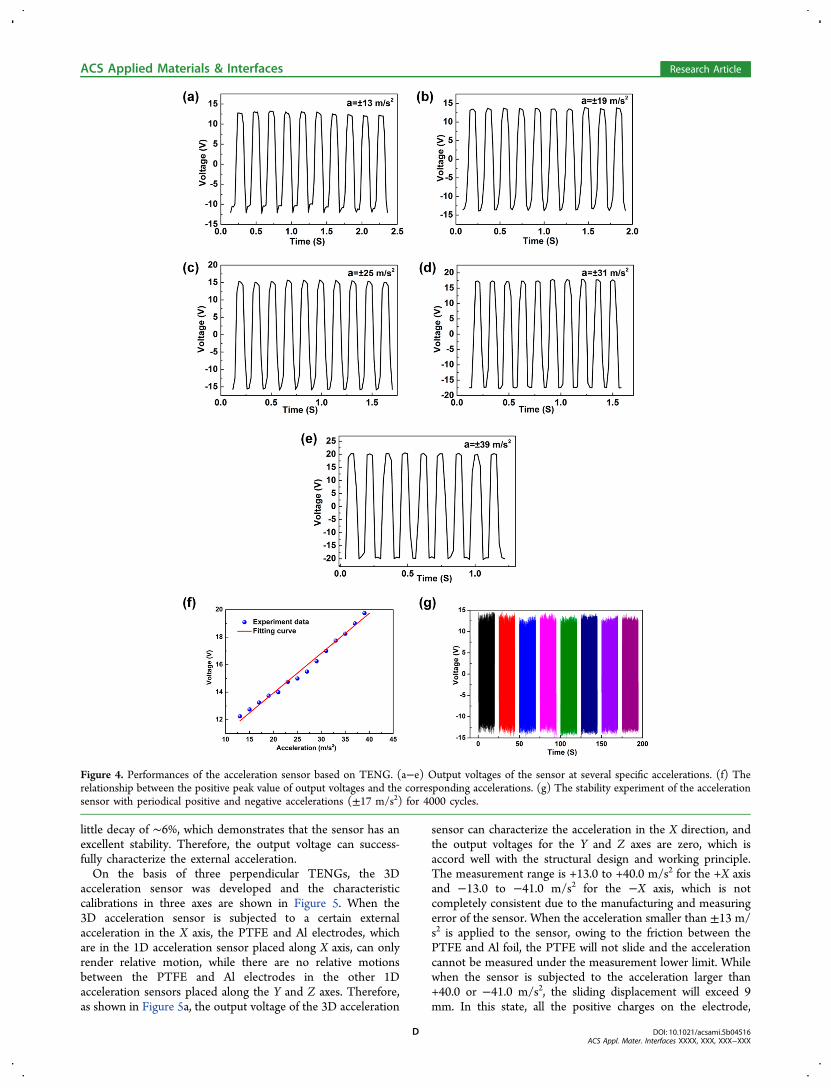
little decay of ∼6%, which demonstrates that the sensor has anexcellent stability. Therefore, the output voltage can success-fully characterize the external acceleration.On the basis of three perpendicular TENGs, the 3D
acceleration sensor was developed and the characteristiccalibrations in three axes are shown in Figure 5. When the3D acceleration sensor is subjected to a certain externalacceleration in the X axis, the PTFE and Al electrodes, whichare in the 1D acceleration sensor placed along X axis, can onlyrender relative motion, while there are no relative motionsbetween the PTFE and Al electrodes in the other 1Dacceleration sensors placed along the Y and Z axes. Therefore,as shown in Figure 5a, the output voltage of the 3D acceleration
sensor can characterize the acceleration in the X direction, andthe output voltages for the Y and Z axes are zero, which isaccord well with the structural design and working principle.The measurement range is +13.0 to +40.0 m/s2 for the +X axisand −13.0 to −41.0 m/s2 for the −X axis, which is notcompletely consistent due to the manufacturing and measuringerror of the sensor. When the acceleration smaller than ±13 m/s2 is applied to the sensor, owing to the friction between thePTFE and Al foil, the PTFE will not slide and the accelerationcannot be measured under the measurement lower limit. Whilewhen the sensor is subjected to the acceleration larger than+40.0 or −41.0 m/s2, the sliding displacement will exceed 9mm. In this state, all the positive charges on the electrode,
Figure 4. Performances of the acceleration sensor based on TENG. (a−e) Output voltages of the sensor at several specific accelerations. (f) Therelationship between the positive peak value of output voltages and the corresponding accelerations. (g) The stability experiment of the accelerationsensor with periodical positive and negative accelerations (±17 m/s2) for 4000 cycles.
ACS Applied Materials & Interfaces Research Article
DOI: 10.1021/acsami.5b04516ACS Appl. Mater. Interfaces XXXX, XXX, XXX−XXX
D

which are completely separate with the PTFE film, will lose theconstraints by the negative charges on the PTFE surface.Therefore, the potential difference of the two Al electrodes willnot increase anymore and the acceleration sensor reaches themeasurement upper limit. Figure 5b and c are the performancesof the 3D acceleration sensor along the Y and Z axes,respectively. They have a similar performance with the onealong the X axis. The detailed characteristics of the 3Dacceleration sensor in three axes are listed in Table 1. The triple
output voltages can characterize the components of the vectoracceleration in the three axes, respectively and independently.Therefore, the 3D acceleration sensor can measure vectoracceleration in any direction. By calculating the three outputvoltages, the vector acceleration can be obtained. As shown inFigure 5d, the red points represent the actual vectoraccelerations and the blue points represent the measuredvector accelerations. It is obvious that the measured 3D vectoraccelerations accord closely with the actual accelerations. Themeasured components of the accelerations in the three axeshave a maximum error of 0.9 m/s2, which is within the standarddeviation range. Therefore, the experimental results demon-strate that the sensor can correctly and effectively measure 3Dvector accelerations in any directions. The detailed measure-ment data are shown in Table 2.A collision experiment is simulated to demonstrate the
application of the 3D acceleration sensor in the vehicle collisionsafety system. Figure 6a is a schematic illustration of the 3Dacceleration sensor for practical application. When a vehiclecollision accident took place, the impact acceleration can bemeasured and the safety air bag can be triggered by theacceleration sensor to protect human life. Generally, the time ofthe vehicle collision is very short and the impact acceleration isusually high, which is beyond the measurement upper limit of
Figure 5. Characteristic calibrations of the 3D acceleration sensor in the three directions and the measurement results of the vector accelerations.(a−c) When the 3D acceleration sensor is subjected to a certain external acceleration in one axis, the 3D acceleration sensor can generate voltage tocharacterize acceleration in this axis, and there is no output voltage signal for the other two axes. (d) Measurement results of five vector accelerations.The measured vector accelerations accord closely with the actual accelerations.
Table 1. Detailed Characteristics of the 3D AccelerationSensor in Three Axes
direction amin (m/s2) amax (m/s
2) S (V·s2/m)a R2 b SD (m/s2)c
−X −13.0 −41.0 0.276 0.977 1.349+X 13.0 40.0 0.289 0.990 0.924−Y −12.9 −41.0 0.264 0.982 1.151+Y 12.6 43.0 0.261 0.978 1.524−Z −14.0 −39.0 0.324 0.977 1.248+Z 14.0 42.0 0.268 0.982 1.151
aS is the sensitivity of the sensor. bR is the coefficient to represent thecorrelation between the fitting curve and the experiment dates. cSD isthe standard deviation.
Table 2. Detailed Measurement Results of the 3D Vector Accelerations
number actual accelerations in three axis (m/s2) measured accelerations in three axis (m/s2) acceleration error (m/s2)
1 (12.1 12.1 12.1) (12.7 12.6 12.8) (0.6 0.5 0.7)2 (17.7 0 −17.7) (18.1 0 −17.3) (0.4 0 −0.4)3 (0 −25.4 17.8) (0 −21.6 17.6) (0 0.7 −0.2)4 (25.0 −20.0 0) (24.8 −20.1 0) (−0.2 0.1 0)5 (−22.0 −22.0 −22.0) (−21.4 −21.1 −21.4) (−0.6 −0.9 −0.6)
ACS Applied Materials & Interfaces Research Article
DOI: 10.1021/acsami.5b04516ACS Appl. Mater. Interfaces XXXX, XXX, XXX−XXX
E
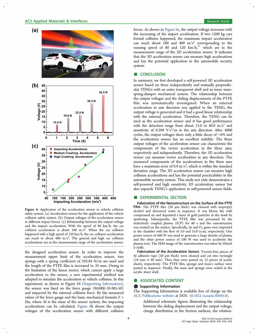
the designed acceleration sensor. In order to improve themeasurement upper limit of the acceleration sensor, twosprings with a spring coefficient of 103.84 N/m are used andthe length of the PTFE film is increased to 35 mm. Owing tothe limitation of the linear motor, which cannot apply a largeacceleration to the sensor, a new experimental method wasadopted to simulate the acceleration in vehicle collision. In thisexperiment, as shown in Figure S4 (Supporting Information),the sensor was fixed on the force gauge (MARK-10-M5-50)and impacted by the external collision force. By the measuredvalues of the force gauge and the basic mechanical formula F =Ma, where M is the mass of the sensor system, the impactingaccelerations can be calculated. Figure 6b shows the outputvoltages of the acceleration sensor with different collision
forces. As shown in Figure 6c, the output voltage increases withthe increasing of the impact acceleration. If two 1200 kg carsfrontal collision happened, the maximum impact accelerationcan reach about 180 and 400 m/s2 corresponding to therunning speed of 80 and 120 km/h,31 which are in themeasurement range of the 3D acceleration sensor. It indicatesthat the 3D acceleration sensor can measure high accelerationsand has the potential application in the automobile securitysystem.
■ CONCLUSIONIn summary, we first developed a self-powered 3D accelerationsensor based on three independently and mutually perpendic-ular TENGs with an outer transparent shell and an inner mass-spring-damper mechanical system. The relationship betweenthe output voltages and the sliding displacements of the PTFEfilm was systematically investigated. When an externalacceleration in axis direction was applied to the TENG, theoutput voltage is generated and it had a good linear relationshipwith the external acceleration. Therefore, the TENG can beused as the acceleration sensor and it has good performancewith the detection range from about 13.0 to 40.0 m/s2 andsensitivity of 0.289 V·s2/m in the axis direction. After 4000cycles, the output voltages show only a little decay of ∼6% andthe acceleration sensor has an excellent stability. The threeoutput voltages of the acceleration sensor can characterize thecomponents of the vector acceleration in the three axes,respectively and independently. Therefore, the 3D accelerationsensor can measure vector acceleration in any direction. Themeasured components of the accelerations in the three axeshave a maximum error of 0.9 m/s2, which is within the standarddeviation range. The 3D acceleration sensor can measure highcollision accelerations and has the potential practicability in theautomobile security system. This study not only demonstrates aself-powered and high sensitivity 3D acceleration sensor butalso expands TENG’s application in self-powered sensor fields.
■ EXPERIMENTAL SECTIONFabrication of the Nanostructure on the Surface of the PTFE
Film. The PTFE film (50 μm thick) was cleaned with isopropyl,alcohol and deionized water in sequence. It was blown dry withcompressed air and deposited a layer of gold particles as the mask bysputtering. Subsequently, the PTFE film was processed by theinductively coupled plasma (ICP) for 40 s and the nanostructurewas created on the surface. Specifically, Ar and O2 gases were importedin the chamber with the flow of 5.0 and 55.0 sccm, respectively. Onepower source of 440 W was used to generate a large density of plasmaand the other power source of 100 W was used to accelerate theplasma ions. The SEM image of the nanostructure was taken by HitachS-5500.
Fabrication of the Acceleration Sensor. Twenty-four pieces ofAl adhesive tape (50 μm thick) were cleaned and cut into rectangle(18 mm × 40 mm). Then they were pasted on 12 pieces of acrylicsheets, respectively. The PTFE film, sponge and mass’s surface werepasted in sequence. Finally, the mass and springs were sealed in theacrylic sheet shell.
■ ASSOCIATED CONTENT*S Supporting InformationThe Supporting Information is available free of charge on theACS Publications website at DOI: 10.1021/acsami.5b04516.
Additional schematic figures illustrating the relationshipbetween the sliding displacement and the output voltage,charge distribution in the friction surfaces, the relation-
Figure 6. Application of the acceleration sensor in vehicle collisionsafety system. (a) Acceleration sensor for the application of the vehiclecollision safety system. (b) Output voltages of the acceleration sensorin different impact forces. (c) Relationship between the output voltageand the impact acceleration. With the speed of 80 km/h, the carcollision acceleration is about 180 m/s2. When the car collisionhappened with a high speed of 120 km/h, the car collision accelerationcan reach to about 400 m/s2. The general and high car collisionaccelerations are in the measurement range of the acceleration sensor.
ACS Applied Materials & Interfaces Research Article
DOI: 10.1021/acsami.5b04516ACS Appl. Mater. Interfaces XXXX, XXX, XXX−XXX
F
ship between the peak value of output voltage, thecorresponding acceleration along the −X direction, andthe experimental method of high accelerations (PDF)
■ AUTHOR INFORMATIONCorresponding Authors*E-mail: [email protected] (Z.L.W.)*E-mail: [email protected] (C.Z.).NotesThe authors declare no competing financial interest.
■ ACKNOWLEDGMENTSThe project is supported by National Natural ScienceFoundation of China (Grant No. 51475099, Grant No.51432005), the “thousands talents” program for the pioneerresearcher, and the Youth Innovation Promotion Association,CAS. We also thank Libo Chen for the discussions.
■ REFERENCES(1) Roylance, L. M. A Miniature Integrated Circuit Accelerometer forBiomedical Application. Ph. D. dissertation, Department of ElectricalEngineering, Stanford University, Stanford, CA,1977.(2) Zimmermann, L.; Ebersohl, J.; Hung, F.; Berry, J. P.; Baillieu, F.;Rey, P.; Diem, B.; Renard, S.; Caillat, P. Airbag Application: AMicrosystem Including a Silicon Capacitive Accelerometer, CMOSSwitched Capacitor Electronics and True Self-test Capability. Sens.Actuators, A 1995, 46, 190−195.(3) Li, G.; Li, Z. H.; Wang, C. S.; Hao, Y. L.; Li, T.; Zhang, D. C.;Wu, G. Y. Design and Fabrication of a Highly Symmetrical CapacitiveTriaxial Accelerometer. J. Micromech. Microeng. 2001, 11, 48−54.(4) Liu, S. F.; Ma, T. H.; Hou, W. Design and Fabrication of a NewMiniaturized Capacitive Accelerometer. Sens. Actuators, A 2008, 147,70−74.(5) Chen, H.; Shen, S. Q.; Bao, M. H. Over-range Capacity of aPiezoresistive Microaccelerometer. Sens. Actuators, A 1997, 58, 197−201.(6) Nemirovsky, Y.; Nemirovesky, A.; Muralt, P.; Setter, N. Design ofa Novel Thin-film Piezoelectric Accelerometer. Sens. Actuators, A 1996,56, 239−249.(7) Hindrichsen, C. C.; Almind, N. S.; Brodersen, S. H.; Lou-Moller,R.; Hansen, K.; Thomsen, E. V. Triaxial MEMS Accelerometer withScreen Printed PZT Thick Film. J. Electroceram. 2010, 25, 108−115.(8) Scheeper, P.; Gullov, J. O.; Kofoed, L. M. A Piezoelectric TriaxialAccelerometer. J. Micromech. Microeng. 1996, 6, 131−133.(9) Yang, Y.; Zhang, H. L.; Zhu, G.; Lee, S.; Lin, Z. H.; Wang, Z. L.Flexible Hybrid Energy Cell for Simultaneously Harvesting Thermal,Mechanical, and Solar Energies. ACS Nano 2013, 7, 785−790.(10) O'Regan, B.; Gratzel, M. A Low-cost, High-efficiency Solar CellBased on Dye-sensitized Colloidal TiO2 Films. Nature 1991, 353,737−740.(11) Xie, Y. N.; Wang, S. H.; Lin, L.; Jing, Q. S.; Lin, Z. H.; Wang, Z.L.; Niu, Z.; Wang, Z. Rotary Triboelectric Nanogenerator Based on aHybridized Mechanism for Harvesting Wind Energy. ACS Nano 2013,7, 7119−7125.(12) Wu, Y. C.; Zhong, X. D.; Wang, X.; Yang, Y.; Wang, Z. L.Hybrid Energy Cell for Simultaneously Harvesting Wind, Solar, andChemical Energies. Nano Res. 2014, 7, 1631−1639.(13) Zhang, H.; Yang, Y.; Su, Y.; Chen, J. J.; Adams, K.; Lee, S.; Hu,C. G.; Wang, Z. L. Triboelectric Nanogenerator for HarvestingVibration Energy in Full Space and as Self-Powered AccelerationSensor. Adv. Funct. Mater. 2014, 24, 1401−1407.(14) Wang, Z. L. Triboelectric Nanogenerators as New EnergyTechnology for Self-powered Systems and as Active Mechanical andChemical Sensors. ACS Nano 2013, 7, 9533−9557.(15) Fan, F. R.; Tian, Z. Q.; Wang, Z. L. Flexible TriboelectricGenerator. Nano Energy 2012, 1, 328−334.
(16) Zhang, C.; Tang, W.; Han, C. B.; Fan, F. R.; Wang, Z. L.Theoretical Comparison, Equivalent Transformation, and ConjunctionOperations of Electromagnetic Induction Generator and TriboelectricNanogenerator for Harvesting Mechanical Energy. Adv. Mater. 2014,26, 3580−359.(17) Tang, W.; Han, C. B.; Zhang, C.; Wang, Z. L. Cover-sheet-basedNanogenerator for Charging Mobile Electronics Using Low-frequencyBody Motion/Vibration. Nano Energy 2014, 9, 121−127.(18) Han, C. B.; Zhang, C.; Tang, W.; Li, X. H.; Wang, Z. L. HighPower Triboelectric Nanogenerator Based on Printed Circuit Board(PCB) Technology. Nano Res. 2015, 8, 722−730.(19) Zhang, C.; Tang, W.; Zhang, L. M.; Han, C. B.; Wang, Z. L.Contact Electrification Field-Effect Transistor. ACS Nano 2014, 8,8702−8709.(20) Zhang, C.; Tang, W.; Pang, Y. K.; Han, C. B.; Wang, Z. L. ActiveMicro-actuators for Optical Modulation Based on a Planar SlidingTriboelectric Nanogenerator. Adv. Mater. 2015, 27, 719−726.(21) Chen, M. X.; Li, X. Y.; Lin, L.; Du, W. M.; Han, X.; Zhu, J.; Pan,C. F.; Wang, Z. L. Triboelectric Nanogenerators as a Self-poweredMotion Tracking System. Adv. Funct. Mater. 2014, 24, 5059−5066.(22) Fan, F. R.; Lin, L.; Zhu, G.; Wu, W. Z.; Zhang, R.; Wang, Z. L.Transparent Triboelectric Nanogenerators and Self-powered PressureSensors Based on Micropatterned Plastic Films. Nano Lett. 2012, 12,3109−3114.(23) Zhu, G.; Yang, W. Q.; Zhang, T.; Jing, Q.; Chen, J.; Zhou, Y. S.;Bai, P.; Wang, Z. L. Self-powered, Ultrasensitive, Flexible TactileSensors Based on Contact Electrification. Nano Lett. 2014, 14, 3208−3214.(24) Lin, L.; Xie, Y. N.; Wang, S. H.; Wu, W. Z.; Niu, S. M.; Wen, X.N.; Wang, Z. L. Triboelectric Active Sensor Array for Self-poweredStatic and Dynamic Pressure Detection and Tactile Imaging. ACSNano 2013, 7, 8266−8274.(25) Yang, Y.; Zhang, H. L.; Lin, Z. H.; Zhou, Y. S.; Jing, Q. S.; Su, Y.J.; Yang, J.; Chen, J.; Hu, C. G.; Wang, Z. L. Human Skin BasedTriboelectric Nanogenerators for Harvesting Biomechanical Energyand as Self-powered Active Tactile Sensor System. ACS Nano 2013, 7,9213−9222.(26) Yu, A. F.; Song, M.; Zhang, Y.; Zhang, Y.; Chen, L. B.; Zhai, J.Y.; Wang, Z. L. Self-powered Acoustic Source Locator in UnderwaterEnvironment Based on Organic Film Triboelectrific Nanogenerator.Nano Res. 2015, 8, 765−773.(27) Yang, J.; Chen, J.; Liu, Y.; Yang, W. Q.; Su, Y. J.; Wang, Z. L.Triboelectrification-based Organic Film Nanogenerator for AcousticEnergy Harvesting and Self-powered Active Acoustic Sensing. ACSNano 2014, 8, 2649−2657.(28) Hu, Y. F.; Yang, J.; Jing, Q. S.; Niu, S. M.; Wu, W. Z.; Wang, Z.L. Triboelectric Nanogenerator Built on Suspended 3D SpiralStructure as Vibration and Positioning Sensor and Wave EnergyHarvester. ACS Nano 2013, 7, 10424−10432.(29) Wang, S. H.; Niu, S. M.; Yang, J.; Lin, L.; Wang, Z. L.Quantitative Measurements of Vibration Amplitude Using a Contact-Mode Freestanding Triboelectric Nanogenerator. ACS Nano 2014, 8,12004−12013.(30) Chen, J.; Zhu, G.; Yang, W.; Jing, Q.; Bai, P.; Yang, Y.; Hou, T.C.; Wang, Z. L. Harmonic-resonator-based Triboelectric Nano-generator as a Sustainable Power Source and a Self-powered ActiveVibration Sensor. Adv. Mater. 2013, 25, 6094−6099.(31) Wagstrom, L.; Thomson, R.; Pipkorn, B. Structural Adaptivityfor Acceleration Level Reduction in Passenger Car Frontal Collisions.Int. J. Crashworthiness 2004, 9, 121−127.
ACS Applied Materials & Interfaces Research Article
DOI: 10.1021/acsami.5b04516ACS Appl. Mater. Interfaces XXXX, XXX, XXX−XXX
G