tribhuvan university institute of engineering …tribhuvan university institute of engineering...
TRANSCRIPT

TRIBHUVAN UNIVERSITYINSTITUTE OF ENGINEERING
CENTRAL CAMPUS, PULCHOWKDEPARTMENT OF ELECTRONICS AND
COMPUTER ENGINEERING
AFINAL YEAR PROJECT REPORT
ONLASER POINTER BASED HUMAN COMPUTER INTERACTION USING
COMPUTER VISION (LP-HCI-CV)
By:Aman Kandoi(69453)
Manika Gartaula(69474)Sraddhanjali Acharya(69490)
Urja Acharya(69497)
LALITPUR, NEPALAugust, 2014

TRIBHUVAN UNIVERSITYINSTITUTE OF ENGINEERING
CENTRAL CAMPUS, PULCHOWK
AFINAL YEAR PROJECT REPORT
ONLASER POINTER BASED HUMAN COMPUTER INTERACTION USING
COMPUTER VISION (LP-HCI-CV)
By:Aman Kandoi(69453)
Manika Gartaula(69474)Sraddhanjali Acharya(69490)
Urja Acharya(69497)
A PROJECT SUBMITTED TO THE DEPARTMENT OF ELECTRONICS ANDCOMPUTER ENGINEERING IN PARTIAL FULFILLMENT OF THE REQUIREMENT
FOR THE BACHELORS DEGREE IN ELECTRONICS AND COMMUNICATIONENGINEERING
DEPARTMENT OF ELECTRONICS AND COMPUTER ENGINEERINGLALITPUR, NEPAL
August, 2014

PAGE OF APPROVAL
The undersigned certify that they have read, and recommended to the Institute of En-gineering for acceptance, this project report entitled “LASER POINTER based HUMANCOMPUTER INTERACTION using COMPUTER VISION” (LP-HCI-CV) submitted byAman Kandoi(69453), Manika Gartaula(69474), Sraddhanjali Acharya(69490) and Urja Acharya(69497) in partial fulfilment of the requirements for the Bachelor’s degree in Electronics &Communication Engineering.
SupervisorDr. Dibakar Raj PantHead of DepartmentDepartment of Electronics & ComputerEngineering
Internal ExaminerProf. Dr. Dinesh Kumar SharmaDepartment of Electronics & ComputerEngineering,Institute of Engineering, Central CampusPulchowk,
External ExaminerEr. Sanjeev Singh KathayatDeputy Director,Civil Aviation Authority of Nepal
Dr. Nanda Bikram AdhikariDeputy HeadDepartment of Electronics & ComputerEngineering,Institute of Engineering, Central CampusPulchowk,Tribhuvan University, Nepal
Dr. Dibakar Raj PantHead of DepartmentDepartment of Electronics & ComputerEngineering,Institute of Engineering, Central CampusPulchowk,Tribhuvan University, Nepal
DATE OF APPROVAL: August 24th, 2014
ii
COPYRIGHT
The author has agreed that the Library, Department of Electronics and Computer En-gineering, Pulchowk Campus, Institute of Engineering may make this report freely availablefor inspection. Moreover, the author has agreed that permission for extensive copying of thisproject report for scholarly purpose may be granted by the supervisors who supervised theproject work recorded herein or, in their absence, by the Head of the Department whereinthe project report was done. It is understood that the recognition will be given to the authorof this report and to the Department of Electronics and Computer Engineering, PulchowkCampus, Institute of Engineering in any use of the material of this project report. Copying orpublication or the other use of this report for financial gain without approval of to the Depart-ment of Electronics and Computer Engineering, Pulchowk Campus, Institute of Engineeringand authors written permission is prohibited.
Request for permission to copy or to make any other use of the material in this reportin whole or in part should be addressed to:
Dibakar Raj Pant, PhDHead of Department,Department of Electronics & Computer Engineering,Institute of Engineering, Central Campus Pulchowk,Tribhuvan University, Nepal
iii

ACKNOWLEDGEMENT
We are highly indebted to the Department of Electronics and Computer Engineering,Central Campus Pulchowk, for providing us with this opportunity of collaborative undertak-ing which has helped us develop a major project of our own that has greatly enhanced ourknowledge and provided us a new experience of team-work, which is quite important for ourfuture endeavours.
We would like to express our deep sense of gratitude to our project supervisor, Dr.Dibakar Raj Pant, Head of Department, Department of Electronics and Computer Engineer-ing, Pulchowk Campus, for providing us with lot of inspiration and intellectual guidancewhile also being very encouraging and supportive throughout the project period.
We would like to acknowledge Prof. Dr. Dinesh Kumar Sharma, Department ofElectronics and Computer Engineering, Pulchowk Campus who guided and supported ourproject.
We would like to express our sincere gratitude to Er. Sanjeev Singh Kathayat, DeputyDirector of Civil Aviation Authority of Nepal, whose immense encouragement and guidancehave been quintessential in the overall success of our project.
We would also like to thank Er. Ruraj Joshi, who guided us in debugging hardwareand software problems related to the project.
We would like to thank the Village Tech Solutions for believing in us and providing usthe opportunity to work on this project.
We would also like to thank Real Time Solutions Pvt. Ltd., and 360 Consultancy Pvt.Ltd., who provided us with workspaces and technical guidances during the project period.
We would like to express our sincere gratitude to the Robotics Club, Central CampusPulchowk and its members for providing us the various machineries and tools required tocomplete the hardware of the project.
We would also like to thank our friends and families, who supported us immenselythroughout the project period.
Lastly, we would like to thank everyone who helped us directly or indirectly during theproject.
iv

ABSTRACT
With the advancement in field of technology, various techniques have been developedwith the aim of improving the interactivity in the education system. As classrooms may con-tain a large number of students each from diverse environment, an effective interaction toolis a necessity these days. The same situation may also arise in the conferences. Video pro-jection is in widespread use for multimedia presentations in classrooms and in conferences.
A particular application is the interactive demonstration of software with a computerwhose screen content is sent to a video beamer. An uncomfortable aspect here is that theusual keyboard/mouse computer limits the possibilities of the speakers by tying them tothe location of the computer with its devices of interaction. To avoid this restriction, wehave developed a system using a common laser pointer tracked by a video camera as aninput device. Video cameras already present in multimedia lecture rooms can be used forthis purpose, which reduces the required overhead compared to special tracking devices,like electro-magnetic ones. Compared to video-based gesture recognition or tracking of apointing stick, video-tracking of a laser point is less sensitive to variations in the ambientlight.
The project is, technically, divided into two parts the software part and the hardwarepart. The hardware part deals with the generation of the pulses at the specified interval tocause the laser to blink with a particular frequency whereas the software part deals withthe detection of the laser pointer on the projected screen and the movement of the mouseaccording to the movement of the laser pointer.
The laser point on the screen is captured by a video camera, and its location recognizedby image processing techniques. The behavior of the point is translated into signals sentto the mouse input of the computer causing the same reactions as if they came from themouse. More complex interaction paradigms are composed from the elementary operationsand pointing of the laser pen.
Keywords: Interactive projector, Computer vision, Human computer interaction
v

TABLE OF CONTENTS
PAGE OF APPROVAL . . . . . . . . . . . . . . . . . . . . . . . . . . . . . . . . ii
COPYRIGHT . . . . . . . . . . . . . . . . . . . . . . . . . . . . . . . . . . . . . iii
ACKNOWLEDGEMENT . . . . . . . . . . . . . . . . . . . . . . . . . . . . . . . iv
ABSTRACT . . . . . . . . . . . . . . . . . . . . . . . . . . . . . . . . . . . . . . v
TABLE OF CONTENTS . . . . . . . . . . . . . . . . . . . . . . . . . . . . . . . vi
LIST OF FIGURES . . . . . . . . . . . . . . . . . . . . . . . . . . . . . . . . . . xi
LIST OF TABLES . . . . . . . . . . . . . . . . . . . . . . . . . . . . . . . . . . . xiii
LIST OF SYMBOLS AND ABBREVIATIONS . . . . . . . . . . . . . . . . . . . xv
1 INTRODUCTION . . . . . . . . . . . . . . . . . . . . . . . . . . . . . . . . . 1
1.1 Background . . . . . . . . . . . . . . . . . . . . . . . . . . . . . . . . . . 1
1.2 Problem Statement . . . . . . . . . . . . . . . . . . . . . . . . . . . . . . 2
1.3 Objectives . . . . . . . . . . . . . . . . . . . . . . . . . . . . . . . . . . . 3
1.4 Scope . . . . . . . . . . . . . . . . . . . . . . . . . . . . . . . . . . . . . 3
1.4.1 Interactive Projector . . . . . . . . . . . . . . . . . . . . . . . . . 3
2 LITERATURE REVIEW . . . . . . . . . . . . . . . . . . . . . . . . . . . . . 5
2.1 Looma and Wand Details . . . . . . . . . . . . . . . . . . . . . . . . . . . 5
2.2 System Operation Description . . . . . . . . . . . . . . . . . . . . . . . . 6
3 BACKGROUND THEORY . . . . . . . . . . . . . . . . . . . . . . . . . . . . 7
vi

3.1 Human-Computer-Interaction (HCI) . . . . . . . . . . . . . . . . . . . . . 7
3.2 Digital Image Processing . . . . . . . . . . . . . . . . . . . . . . . . . . . 7
3.3 Embedded System . . . . . . . . . . . . . . . . . . . . . . . . . . . . . . . 9
4 Tools Used . . . . . . . . . . . . . . . . . . . . . . . . . . . . . . . . . . . . . 10
4.1 Hardware . . . . . . . . . . . . . . . . . . . . . . . . . . . . . . . . . . . 10
4.1.1 Proteus VSM . . . . . . . . . . . . . . . . . . . . . . . . . . . . . 10
4.1.2 Eagle . . . . . . . . . . . . . . . . . . . . . . . . . . . . . . . . . 10
4.1.3 AVR Studio 6 . . . . . . . . . . . . . . . . . . . . . . . . . . . . . 10
4.1.4 SinaProg . . . . . . . . . . . . . . . . . . . . . . . . . . . . . . . 10
4.2 Software implementation and simulation . . . . . . . . . . . . . . . . . . . 11
4.2.1 Python . . . . . . . . . . . . . . . . . . . . . . . . . . . . . . . . . 11
4.2.2 Open Source Computer Vision Library (OpenCV) . . . . . . . . . . 11
4.2.3 Tkinter . . . . . . . . . . . . . . . . . . . . . . . . . . . . . . . . 12
4.2.4 Picamera . . . . . . . . . . . . . . . . . . . . . . . . . . . . . . . 12
4.2.5 PyMouse . . . . . . . . . . . . . . . . . . . . . . . . . . . . . . . 12
5 SYSTEM DEVELOPMENT . . . . . . . . . . . . . . . . . . . . . . . . . . . 14
5.1 Projected Screen of Looma . . . . . . . . . . . . . . . . . . . . . . . . . . 14
5.2 System Block Diagram and Description . . . . . . . . . . . . . . . . . . . 14
6 METHODOLOGY . . . . . . . . . . . . . . . . . . . . . . . . . . . . . . . . . 16
6.1 Initial Calibration of Projected Screen . . . . . . . . . . . . . . . . . . . . 16
6.2 Detection of Laser Pointer . . . . . . . . . . . . . . . . . . . . . . . . . . 18
6.2.1 Dynamic Exposure Correction . . . . . . . . . . . . . . . . . . . . 18
6.2.2 Brightest Pixel Detection . . . . . . . . . . . . . . . . . . . . . . . 18
vii

6.3 Microcontroller to generate laser pulses . . . . . . . . . . . . . . . . . . . 19
6.4 Hardware Implementation . . . . . . . . . . . . . . . . . . . . . . . . . . . 20
6.4.1 Laser Wand . . . . . . . . . . . . . . . . . . . . . . . . . . . . . . 20
6.4.2 Components of Laser Wand . . . . . . . . . . . . . . . . . . . . . 20
6.5 Finalized algorithm for click and drag . . . . . . . . . . . . . . . . . . . . 21
6.6 Communication between computer and RPi . . . . . . . . . . . . . . . . . 21
6.7 Movement of Mouse Pointer . . . . . . . . . . . . . . . . . . . . . . . . . 22
7 PROBLEM FACED and SOLUTIONS . . . . . . . . . . . . . . . . . . . . . . 24
7.1 Laser Hardware . . . . . . . . . . . . . . . . . . . . . . . . . . . . . . . . 24
7.2 Detection of laser point by HSV Segmentation . . . . . . . . . . . . . . . . 24
7.3 Slow detection and action by RPi . . . . . . . . . . . . . . . . . . . . . . . 24
8 RESULTS AND ANALYSIS . . . . . . . . . . . . . . . . . . . . . . . . . . . 26
8.1 Hardware Testing . . . . . . . . . . . . . . . . . . . . . . . . . . . . . . . 26
8.1.1 Testing the Laser Circuit . . . . . . . . . . . . . . . . . . . . . . . 26
8.2 Software Testing . . . . . . . . . . . . . . . . . . . . . . . . . . . . . . . 27
8.2.1 Algorithm Test . . . . . . . . . . . . . . . . . . . . . . . . . . . . 27
8.2.2 System Test . . . . . . . . . . . . . . . . . . . . . . . . . . . . . . 27
9 COST ANALYSIS . . . . . . . . . . . . . . . . . . . . . . . . . . . . . . . . . 28
9.1 Cost Comparison between Looma System and Our System . . . . . . . . . 28
9.2 Total Cost of Our Project . . . . . . . . . . . . . . . . . . . . . . . . . . . 29
10 LIMITATIONS AND FUTURE ENHANCEMENTS . . . . . . . . . . . . . . 30
10.1 Limitations . . . . . . . . . . . . . . . . . . . . . . . . . . . . . . . . . . 30
viii

10.2 Enhancements . . . . . . . . . . . . . . . . . . . . . . . . . . . . . . . . . 30
11 CONCLUSION . . . . . . . . . . . . . . . . . . . . . . . . . . . . . . . . . . . 31
11.1 Conclusion . . . . . . . . . . . . . . . . . . . . . . . . . . . . . . . . . . 31
REFERENCES . . . . . . . . . . . . . . . . . . . . . . . . . . . . . . . . . . . . . 32
APPENDIX A TCP PROTOCOL . . . . . . . . . . . . . . . . . . . . . . . . . . 33
APPENDIX B CAMERA MOUNT . . . . . . . . . . . . . . . . . . . . . . . . . 34
APPENDIX C RPi AMOUNT LOOMA . . . . . . . . . . . . . . . . . . . . . . 35
APPENDIX D RPi AND CAMERA BOARD . . . . . . . . . . . . . . . . . . . . 36
APPENDIX E RPi BOARD . . . . . . . . . . . . . . . . . . . . . . . . . . . . . 37
APPENDIX F RPi CAMERA MODULE . . . . . . . . . . . . . . . . . . . . . . 38
APPENDIX G SIMULATION OF LASER HARDWARE . . . . . . . . . . . . . 39
APPENDIX H LASER CIRCUIT SCHEMATIC . . . . . . . . . . . . . . . . . 40
APPENDIX I LASER CIRCUIT EAGLE DESIGN . . . . . . . . . . . . . . . 41
APPENDIX J FINAL LASER HARDWARE . . . . . . . . . . . . . . . . . . . 42
APPENDIX K FABRICATED LASER CIRCUIT . . . . . . . . . . . . . . . . . 43
APPENDIX L AVR ATMEGA 8L FEATURES . . . . . . . . . . . . . . . . . . 44
APPENDIX M AVR ATMEGA8L PIN DIAGRAM . . . . . . . . . . . . . . . . 45
ix

APPENDIX N STATE DIAGRAM . . . . . . . . . . . . . . . . . . . . . . . . . 46
APPENDIX O FLOWCHART OF THE ALGORITHM . . . . . . . . . . . . . 47
APPENDIX P BEFORE EXPOSURE CORRECTION . . . . . . . . . . . . . . 49
APPENDIX Q AFTER EXPOSURE CORRECTION . . . . . . . . . . . . . . . 50
x

LIST OF FIGURES
Figure 1.1 Interactive Projector System . . . . . . . . . . . . . . . . . . . . . . 3
Figure 2.1 Hardware and Electrical parts of Looma system . . . . . . . . . . . 5
Figure 2.2 3D printed hacked Wii Remote wand . . . . . . . . . . . . . . . . . 6
Figure 2.3 Illustration of the movement of infrared picked up by the Wiimote . 6
Figure 5.1 Looma Software . . . . . . . . . . . . . . . . . . . . . . . . . . . . 14
Figure 5.2 System Block Diagram . . . . . . . . . . . . . . . . . . . . . . . . 15
Figure 6.1 System Methodology . . . . . . . . . . . . . . . . . . . . . . . . . 17
Figure 8.1 PWM generation on button click . . . . . . . . . . . . . . . . . . . 26
Figure A.1 Transmission Control Protocol between Server and Client . . . . . . 33
Figure B.1 Custom Camera Mount . . . . . . . . . . . . . . . . . . . . . . . . 34
Figure C.1 RPi amount looma hardware . . . . . . . . . . . . . . . . . . . . . 35
Figure E.1 RPi Board . . . . . . . . . . . . . . . . . . . . . . . . . . . . . . . 37
Figure F.1 RPi Camera Module . . . . . . . . . . . . . . . . . . . . . . . . . . 38
Figure G.1 Laser Hardware Simulation . . . . . . . . . . . . . . . . . . . . . . 39
Figure H.1 Laser circuit schematic . . . . . . . . . . . . . . . . . . . . . . . . 40
Figure I.1 Laser circuit eagle design diagram . . . . . . . . . . . . . . . . . . 41
Figure J.1 Final Laser Hardware . . . . . . . . . . . . . . . . . . . . . . . . . 42
Figure K.1 Laser circuit fabricated design . . . . . . . . . . . . . . . . . . . . . 43
Figure M.1 AVR Atmega8L Pin Diagram . . . . . . . . . . . . . . . . . . . . . 45
Figure N.1 State Diagram . . . . . . . . . . . . . . . . . . . . . . . . . . . . . 46
Figure O.1 Flowchart of the algorithm . . . . . . . . . . . . . . . . . . . . . . 47
Figure O.2 Flowchart of the algorithm . . . . . . . . . . . . . . . . . . . . . . 48
xi

Figure P.1 Projected Screen Before Exposure Correction . . . . . . . . . . . . 49
Figure Q.1 Projected Screen After Exposure Correction . . . . . . . . . . . . . 50
xii

LIST OF TABLES
Table 9.1 Cost Comparison between Existing System and Our System . . . . . 28
Table 9.2 Total Cost of Our Project . . . . . . . . . . . . . . . . . . . . . . . . 29
xiii

List of Acronyms
2D 2 Dimensional
3D 3 Dimensional
AVR Advanced Virtual RISC
CPU Central Processing Unit
CSI Camera Serial Interface
CV Computer Vision
EEPROM Electrically Erasable Programmable Read Only Memory
FPGA Field Programmable Gate Array
GCC GNU Compiler Collection
GNU Gnu’s Not Unix
GUI Graphical User Interface
HD High Definition
Hrs Hours
HSV Hue-Saturation-Value
Hz Hertz
I/O Input/Output
I2C Inter-Integrated Circuit
ICT Information and Communication Technology
IDLE Integrated DeveLopment Environment
IR Infra-Red
ISR Interrupt Service Routine
IT Information Technology
L Low
LASER Light Amplification by Stimulated Emission of Radiation
LED Light Emitting Diode
MATLAB Mathematical Laboratory
MOT Muti-Object Tracking
xiv

mW milliWatt
NPN Negative-Positive-Negative
nm nanometer
PC Personal Computer
PCB Printed Circuit Board
PWM Pulse Width Modulation
RGB Red Green Blue
RISC Reduced Instruction Set Computer
ROI Region of Interest
RPi Raspberry Pi
STL Standard Template Library
TCP Transmission Control Protocol
USB Universal Serial Bus
USD United States Dollar
VSM Virtual System Modelling
VTS Village Tech Solutions
V Volt
W Watt
WWW World Wide Web
xv

1 INTRODUCTION
1.1 Background
According to the Information and Communication Technology (ICT) Master Plan 2013-2017 [1], the long term goal of education in Nepal is to provide citizens with appropriateknowledge, skills and attitude to work actively in the development of the country and to in-tegrate Nepal into the global community through ensuring equitable access to and quality ofeducation for all. In this context, the Ministry of Education has considered the use of ICT asessential to achieve the goals of education. And the prime components of it are:
1. ICT infrastructure including internet connectivity
2. Human resources well trained in the use of the ICT infrastructure
3. Availability of the Teaching / Learning Materials in the ICT infrastruc- ture
4. System Enhancement procedures
Village Tech Solutions (VTS) which was established in the year 1996 by David andHyadi Sowerwine, with the mission to provide safe, efficient and inexpensive energy systemsfor the people of rural Nepal. VTS had been endeavoring to bring audio-visual system to theclassrooms of Nepal to enhance their current education since the year 2008. By introducingsuch multimedia systems into the classroom, their aim is to make standard learning materialsavailable to all Nepalese students irrespective of their socio-economic statuses. The infor-mation that can be gained from the introduction of such multi-media to rural villages canhelp not only the standard of education, but also the standard of living.
The device has been named Looma. Looma is a portable projection system that usesa wand to navigate the screen, like an interactive projector system. Looma is an affordableand low power consuming audio-visual technology device which will provide an interactivewindow to internet and access to educational contents to village schools that have never seencomputers, or in some cases, even books.
And now with the release of ICT master plan for education, the government of Nepalhas been cooperating with VTS regarding the same. Also, VTS has been collaborating withstudents and enthusiasts for the optimization of Looma, with the main aim to make Loomaaffordable, less power consuming and efficient, so that the people of rural communities canderive maximum advantage from it.
Projector systems project on the screen the contents of the computer connected to it.By the use of various technologies, we can increase the interactivity of projector systems.Our project tries to improve the interactivity and the cost of the existing Looma system suchthat it can be afforded by rural schools. The use of camera to capture the projected area,
1

and detection of location of a visual pen or other visual tools, altogether form an interactiveprojector system.
With the use of a camera, and laser pen, our project gets scoped under Human Com-puter Interaction(HCI). Computer Vision(CV) is an integral part of the interaction. Thevision based HCI acts as an apt mediator between the user and the computer. In its long termgoals, our project aims to lay a foundation to improved interaction with exisiting projectionsystems using our hardware and software.
1.2 Problem Statement
The existing wand system of Looma is basically an IR based handheld device that actsas a mouse. It emits IR light, and also called a light pen. The major components of it are thatit has an IR LED, a button and and on/off switch and uses 555 timer to turn the IR light sourceon/off. The led is blinked at a pre-determined frequency so that the blink is be analysed asa click by its camera processor. The current design uses Nintendo Wii IR camera, which isscavenged from Wii motes in order to detect the IR light on the projected screen. Some ofthe system’s issues which can not be ignored are:
1. Drawing in the Whiteboard: While drawing in the Looma software, the tracking ofthe IR led is very unreliable and the drawings are not made as expected.
2. Use of Pre-built Multi-Object-Tracking(MOT) processor: There is the use of in-built MOT processor in the camera chip, which does part of the image processingand tracking and sending coordinates. In the case of errors, its response can not bemodified to remove errors which makes it inefficient
3. Errors not detectable: Since the Wiimote used IR to move the mouse, the location ofthe IR on the screen is not visible with the naked eye thus making errors not detectable
4. Unavailability in the market: Wiimote IR camera chip being used in the system cannot be readily bought in the open market which makes it difficult to mass produce thesystem
5. Coverage and Difficult to Interact: Wii wand is not interactive enough and workseffectively only within the projected screen space which makes interacting with thescreen difficult and not intuitive
In short, hacked Wii Remotes [2] along with the Field Programmable Gate Array(FPGA) board is adding up to the cost significantly. In addition, the system is not verystable and is inefficient to use as points aforementioned, thereby leading to the research onalternative vision-based HCIs and our project is an effort to get a prototype of one suchalternative.
2

Projector
Laser Point on
the Projected
Screen
Camera
Interaction
SystemComputer
Image Image
Image
ControlImage
Figure 1.1: Interactive Projector System
1.3 Objectives
The basic objectives of our project is make prototype for an alternative type of vision-based HCIs and in the modification of Project Looma in aspects listed below:
1. To use laser pointer instead of IR (Infra-red) based interaction
2. To remove the Wii technology, and its dependencies used in current prototype thereby,making the system efficient and cost effective
1.4 Scope
1.4.1 Interactive Projector
Projector systems do not have anything to project on the screen without any computerconnected to it. So the images projected by the projectors come from the computer con-nected to it. Interactivity in such projector systems can be enabled by the use of varioustechnologies. If there is a camera on a board used as projection area, and which locates theposition of the pen or other visual tool when touching on the board, this would be an inter-active whiteboard. Such whiteboards are used by schools and universities to get maximuminvolvement of students in their learning.
In addition to that, it also reduce the need of IT infrastructures since students can learnfrom a single board present in the classrooms, unlike the use of individual computers foraudio-visual learning. Also, another way of interactivity can be one where the interactivitycan be done right from the projector itself. If the technology for interaction, for example the
3

camera and processor to locate the position of pen, nger or any visual tool are used right onthe projector, this makes up an interactive projector system.
As seen in the figure 1.1, the laser point on the projected screen of the projector is cap-tured by the camera and sent to the interaction system which in turns sends the device beingprojected some control actions to perform. Based on the detection of the laser, some actionsare remotely performed on the computer, thereby controlling tasks on it. Such systems aremore advantageous than the use of whiteboards from security perspective, maintenance per-spective, etc. If any part of the system is damaged, a part of it can be changed or modifiedthus making maintenance and replacement a good choice in the case of interactive projectors.Also, the ways of interacting with the projector screen can be upgraded and modified withsignificantly less cost than in the case of interactive whiteboards.
Interactive Projectors makes sense for the users who want the combination of projectorand interactive whiteboard in an individual system.
4

2 LITERATURE REVIEW
The current prototype can run off a rechargeable 12V battery, has the capability toaccess the World Wide Web(WWW), has readily available off line content, via establishedpartnerships, and has an extremely easy to use interface. The device is contained in a singleunit with replaceable external components (i.e. keyboard, remotes), consumes less than 100W of power, and will cost only USD 300. The system is about the size of a shoe-box. Asseen in the figure 2.1 and 2.2, the existing Looma system functional parts can be listed asbelow:
2.1 Looma and Wand Details
1. 300 lumen projector
2. Internet Connected
3. Wireless Wand control from front of room
4. Audio output for large room setting
5. Rechargeable 12V battery (8Hrs per charge)
6. Computer: Panda board
7. External ports: 1 Ethernet
8. Custom power supply (12V in 5V, 12V, 19.5V out)
9. Hacked Wii IR Camera and Wii wands
Figure 2.1: Hardware and Electrical parts of Looma system
5

Wand control descriptions:
1. Wand shown in the figure is a 3D printed IR light source
2. The wand design uses 555 timer to turn the IR light source on/off at a pre-determinedfrequency such that the blink can be interpreted as a click on the device
3. Current design uses Nintendo Wii IR camera, which are scavenged from Wii motes
Figure 2.2: 3D printed hacked Wii Remote wand
2.2 System Operation Description
Figure 2.3: Illustration of the movement of infrared picked up by the Wiimote
The existing system uses Wii Remote to interact in the audio-visual device. This sys-tem uses an Wii IR camera which picks up the infrared light source, and tracks it using itsMulti-Object Tracking (MOT) processor present in the camera chip as shown in the figure2.3. Wii IR Camera gives out a pre-set Inter-Integrated Circuit (I2C) address so the interfaceboard needs an I2C multiplexer. To convert the I2C output to serial, and to demultiplex thesignals, the system has been using an FPGA board.
6

3 BACKGROUND THEORY
3.1 Human-Computer-Interaction (HCI)
HCI is the study of how people interact with computers and to what extent computersare or are not developed for successful interaction with human beings. Developing human-computer interactions involves design on both sides of the interaction. On the technologyside, the designer must have a thorough understanding of the available hardware and softwarecomponents and tools. On the human side, the designer must have a good understanding ofhow humans learn and work with computers, including envisioning new modes of working.The designer’s task is to create effective, efficient, and satisfying interactions by balanc-ing factors such as cost, benefits, standards, and the environmental constraints in which theinteraction will take place.
Classrooms today are filled with a diverse range of students. Many of them are com-puter literate while others are not. Some are primarily visual learners, some are auditorylearners and some kinesthetic. Others may be gifted and talented.Still others may strug-gle with physical, mental, behavioral or emotional challenges. In such diverse environ-ment, it may be difficult for the teacher to cope up with each and every individual. In suchcases, an effective human-computer interaction tool plays a pivotal role.Various tools arenow available for the efficient human-computer interaction, one of which is the InteractiveSmart Board.
The Smart Board is an interactive whiteboard that uses touch detection for user input(for example scrolling and right mouse-click) in the same way as normal PC input devices.The Smart Board interactive whiteboard operates as part of a system that includes the inter-active whiteboard, a computer, a projector and whiteboarding software which can be usedin various areas like offices, schools,etc.Among the various areas of application of human-computer interaction, education systems are more likely to benefit from its use.
3.2 Digital Image Processing
An image may be defined as a two-dimensional function, f(x, y), where x and y arespatial (plane) coordinates, and the amplitude of f at any pair of coordinates (x, y) is calledthe intensity or gray level of the image at that point. [3] When x, y, and the amplitude valuesof f are all finite, discrete quantities, we call the image a digital image. The field of digitalimage processing refers to processing digital images by means of a digital computer. Imageprocessing can be defined method to convert an image into digital form and perform someoperations on it, in order to get an enhanced image or to extract some useful informationfrom it. It is a type of signal dispensation in which input is image, like video frame orphotograph and output may be image or characteristics associated with that image. UsuallyImage Processing system includes treating images as two dimensional signals while applying
7
already set signal processing methods to them. Image processing algorithm library such asOpen Computer Vision is used which gives a wide range of features.
The basic stages used in image processing are described as follows:
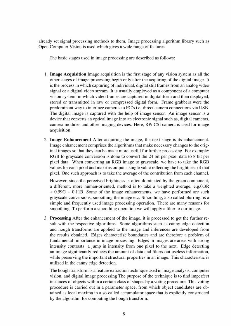
1. Image Acquisition Image acquisition is the first stage of any vision system as all theother stages of image processing begin only after the acquiring of the digital image. Itis the process in which capturing of individual, digital still frames from an analog videosignal or a digital video stream. It is usually employed as a component of a computervision system, in which video frames are captured in digital form and then displayed,stored or transmitted in raw or compressed digital form. Frame grabbers were thepredominant way to interface cameras to PC’s i.e. direct camera connections via USB.The digital image is captured with the help of image sensor. An image sensor is adevice that converts an optical image into an electronic signal such as, digital cameras,camera modules and other imaging devices. Here, RPi CSI camera is used for imageacquisition.
2. Image Enhancement After acquiring the image, the next stage is its enhancement.Image enhancement comprises the algorithms that make necessary changes to the orig-inal images so that they can be made more useful for further processing. For example:RGB to grayscale conversion is done to convert the 24 bit per pixel data to 8 bit perpixel data. When converting an RGB image to grayscale, we have to take the RGBvalues for each pixel and make as output a single value reflecting the brightness of thatpixel. One such approach is to take the average of the contribution from each channel.
However, since the perceived brightness is often dominated by the green component,a different, more human-oriented, method is to take a weighted average, e.g.0.3R+ 0.59G + 0.11B. Some of the image enhancements, we have performed are suchgrayscale conversions, smoothing the image etc. Smoothing, also called blurring, is asimple and frequently used image processing operation. There are many reasons forsmoothing. To perform a smoothing operation we will apply a filter to our image.
3. Processing After the enhancement of the image, it is processed to get the further re-sult with the respective algorithms. Some algorithms such as canny edge detectionand hough transforms are applied to the image and inferences are developed fromthe results obtained. Edges characterize boundaries and are therefore a problem offundamental importance in image processing. Edges in images are areas with strongintensity contrasts a jump in intensity from one pixel to the next. Edge detectingan image significantly reduces the amount of data and filters out useless information,while preserving the important structural properties in an image. This characteristic isutilized in the canny edge detection.
The hough transform is a feature extraction technique used in image analysis, computervision, and digital image processing The purpose of the technique is to find imperfectinstances of objects within a certain class of shapes by a voting procedure. This votingprocedure is carried out in a parameter space, from which object candidates are ob-tained as local maxima in a so-called accumulator space that is explicitly constructedby the algorithm for computing the hough transform.
8

4. Recognition Once the processing operations are completed, the required algorithmsare applied for the feature recognition such as laser detection in our case. Here, therecognised feature is the laser pointer on the projector screen.
3.3 Embedded System
A microcontroller is a self-contained system with peripherals, memory and a processorthat can be used as an embedded system. Most programmable microcontrollers that are usedtoday are embedded in other consumer products or machinery including phones, peripherals,automobiles and household appliances for computer systems. Due to that, another name fora microcontroller is an embedded controller.
Some embedded systems are more sophisticated, while others have minimal require-ments for memory and programming length and a low software complexity. An embed-ded system is an engineering artifact involving computation that is subject to physical con-straints(reaction constraints and execution constraints) arising through interactions of com-putational processes with the physical world. Reaction constraints originate from the be-havioural requirements, throughput, and jitter whereas execution constraints originate fromthe implementation requirements and put bounds on available processor speeds, power,memory and hardware failure rates. The key to embedded systems design is to obtain desiredfunctionality under both kinds of constraints.
Embedded systems are application specific and single functioned and efficiency is ofparamount importance for embedded systems. They are optimized for energy, code size, ex-ecution time, weight and dimensions, and cost.These sysems are typically designed to meetreal time constraints; a real time system reacts to stimuli from the controlled object or opera-tor within the time interval dictated by the environment. For real time systems, right answersarriving too late (or even too early) are wrong. Also they often interact (sense, manipulateand communicate) with external world through sensors and hence are typically reactive sys-tems; a reactive system is in continual interaction with the environment and executes at apace determined by that environment. They generally have minimal or no user interface.
9

4 Tools Used
4.1 Hardware
4.1.1 Proteus VSM
The Proteus VSM contains mixed mode SPICE circuit simulation, animated compo-nents and microcontroller models to facilitate co-simulation of complete microcontrollerbased design. It is possible to develop and test such designs before a physical prototype isconstructed. This is possible because interaction with the design is possible using circuit in-dicators like LED, display panels, actuators etc. It also provides extensive debugging facilityby employing breakpoints, single stepping and variable display of both assembly code andhigh level language source code.
4.1.2 Eagle
Eagle is acronym for Easily Applicable Graphical Layout which is a flexible, expand-able and scriptable schematic capture editor, PCB layout editor and auto-router developedby CadSoft Computer.
4.1.3 AVR Studio 6
AVR Studio 6 is a software development environment developed by Atmel. It is a fullsoftware development with an editor, simulator, programmer, etc. It comes with its own inte-grated C compiler, the AVR GNU C Compiler (GCC). It also supports several programmersincluding the STK500, AVR Dragon, etc.
4.1.4 SinaProg
SinaProg is Hex downloader application with AVRDude and Fuse Bit Calculator. Thisis used to download code/program and to set fuse bits of all AVR based microcontrollers.
10

4.2 Software implementation and simulation
4.2.1 Python
IDLE is an integrated development environment for Python, which has been bundledwith each release of the language. It is packaged as an optional part of the Python packagingwith many Linux distributions. It is completely written in Python and the Tkinter GUI toolkit(wrapper functions for Tcl/Tk).According to the included README, its main features are:
1. Multi-window text editor with syntax highlighting, auto completion, smart indent andother.
2. Python shell with syntax highlighting.
3. Integrated debugger with stepping, persistent breakpoints, and call stack visibility.
4.2.2 Open Source Computer Vision Library (OpenCV)
OpenCV is an open-source Berkeley Software Distribution (BSD)-licensed library thatincludes several hundreds of computer vision algorithms. It focuses mainly on real- time im-age processing. OpenCV library has been used in python platform. OpenCV has a modularstructure, which means that the package includes several shared or static libraries.
OpenCV is an open source computer vision and machine learning software library.OpenCV was built to provide a common infrastructure for computer vision applications andto accelerate the use of machine perception in the commercial products. Being a BSD-licensed product, OpenCV makes it easy for businesses to utilize and modify the code. Thelibrary has more than 2500 optimized algorithms, which includes a comprehensive set ofboth classic and state-of-the-art computer vision and machine learning algorithms.
These algorithms can be used to detect and recognize faces, identify objects, classifyhuman actions in videos, track camera movements, track moving objects, extract 3D modelsof objects, produce 3D point clouds from stereo cameras, stitch images together to producea high resolution image of an entire scene, find similar images from an image database,remove red eyes from images taken using flash, follow eye movements, recognize sceneryand establish markers to overlay it with augmented reality, etc.
1. core - a compact module defining basic data structures, including the dense multidi-mensional array Mat and basic functions used by all other modules.
2. imgproc - an image processing module that includes linear and non-linear image filter-ing, geometrical image transformations (resize, affine and perspective warping, generictable-based remapping), color space conversion, histograms, and so on.
11

3. video - a video analysis module that includes motion estimation, background subtrac-tion, and object tracking algorithms.
4. calib3d - basic multiple-view geometry algorithms, single and stereo camera calibra-tion, and object pose estimation, stereo correspondence algorithms, and elements of3D reconstruction.
5. features2d - salient feature detectors, descriptors, and descriptor matchers.
6. objdetect - detection of objects and instances of the predefined classes (for example,faces, eyes, mugs, people, cars, and so on).
7. highgui - an easy-to-use interface to video capturing, image and video codecs, as wellas simple UI capabilities.
8. gpu - GPU-accelerated algorithms from different OpenCV modules. It also includessome other helper modules, such as FLANN and Google test wrappers, Python bind-ings, and others.
4.2.3 Tkinter
It is a standard builds of Python include an object-oriented interface to the Tcl/Tkwidget set, called Tkinter. This is probably the easiest to install and use. The Tkinter module(Tk interface) is the standard Python interface to the Tk GUI toolkit. Both Tk and Tkinter areavailable on most Unix platforms, as well as on Windows systems. Tcl/Tk is fully portableto the MacOS, Windows, and Unix platforms. The Tkinter module is a thin object-orientedlayer on top of Tcl/Tk. Tkinter is a set of wrappers that implement the Tk widgets as Pythonclasses. In addition, the internal module tkinter provides a threadsafe mechanism whichallows Python and Tcl to interact. Tkinters chief virtues are that it is fast.
4.2.4 Picamera
RPi camera module can use Picamera 1.2. It is a pure Python interace to the cameramodule. The interface eradicates the need to use command line syntax for grabbing imageframes and videos. It does not cause restart of the camera interfaces when changing theintrinsic camera properties .
4.2.5 PyMouse
It is a pure Python cross-platform mouse control module. Mouse functions are pro-vided by the PyMouse library. It runs on any Linux system running over X11 display server.
12

PyMouse provides simple functions like move, click, press and release. PyMouse is a wrap-per over Python X Library. It is used to move the mouse pointer as per the laser pointermovements. It is a fully functional X client library intended for Python programs, work-ing as client to communicate with the X server via the X protocol. It runs on Linux usingXFree86 as the server and most Unices.
The X Window System is a network-transparent window system that was designed atMIT. X display servers run on computers with either monochrome or color bitmap displayhardware. Once the connection is set up, the Xlib macros are used to get the informationabout the current display. Similarly, using the X objects, the mouse pointer is moved bysending coordinates to the appropriate functions.
13

5 SYSTEM DEVELOPMENT
5.1 Projected Screen of Looma
The Looma software can run on any linux hardware. When the power is supplied tothe Looma hardware, the system boots up. The educational Looma software starts up andonce the projector button is turned on, we can see the looma software, as show in the figure5.1. Once the device is up, there are options of whether to use the wand or not use the wand.
Figure 5.1: Looma Software
We ignore these options and use our own system to interact with the computer.
5.2 System Block Diagram and Description
System comprises of a detection system, which is made up of Rpi camera and Rpiboard. They send control information to Looma system for the desired actions.
The detection system is set to grab frames of width = 640 and height = 480. The de-tection system is kept at a pre-calculated distance, such that the projected screen is obtainedin the grabbed frame. The camera is set to capture a video with 24 frames per second. In thegrabbed frame, only the projected screen is our required region of interest within which themonitoring and detection of laser spots is done. The region of interest is extracted and thefour corners of it are used to map the laser point in the coordinate system of the computer.
The arrangement of the detection system and the Looma system is done in such a waythat, the images are undistorted and unwarped. This assumption allows us to then furtherour calculations based on linear mapping. The linear mapping is done to map the imagecoordinates from Rpi to the display resolution of the computer.
14

Figure 5.2: System Block Diagram
The next task is updating mouse as per the laser point’s actions. In all conditions,whenever laser point is seen inside the projected screen, the mouse pointer move commandis given to the Looma system. Based on the number of blinks of the laser point, mouse downor release actions are performed by the Looma system.
Here, the detection system is made a client to the server running in the Looma system.All the image processing tasks are handled by the detection system.
The communication between the detection system and the computer system is done viaclient server architecture as shown in the Appendix A.1. The architecture of communicationis Transmission Control Protocol. TCP provides a reliable, ordered and error-checked deliv-ery of a stream of octets between programs running on computers connected to a local areanetwork, intranet or the public Internet. It resides at the transport layer. For our assembledsystem, see Appendix B.1 and C.1.
15

6 METHODOLOGY
The main purpose of the reformed wand is to establish a way of interaction betweenthe user and the projector system. Hence, this system needs to accomplish the followingtasks to overcome the limitations provided by the current Looma wand system:
1. Get sequence of frames from the real-time video of the projected screen
2. Use of laser light instead of infra-red for greater flexibility in the use of mouse pointer
3. Detect lasers on or off states in each frame using image processing algorithms
4. Based on the results of detection, generate appropriate mouse press and release actionsto operate mouse
6.1 Initial Calibration of Projected Screen
The projected screen is our region of interest. The four corners of the projected screenare first extracted, which is where we want our laser point to be detected within.
The projected screen is distinguished from the wall surface by applying a thresholdon the grayscale image. The applied threshold binarized the captured image such that, thegrayscale image is turned into a binarized image. The projected screen is thresholded intoa white surface and the rest of the image is seen as black. The contour finding algorithmis applied to this image. The contour with the largest area, which is the projected screen isobtained. The rectangular approximation of this contour gives the x and y coordinates of theprojected screen.
The obtained coordinates are in the image plane coordinate system, which needs to bemapped to the projected computers screen coordinates. First of all, the x and y coordinatesof the obtained projected screen is translated to the origin of the image plane coordinateThe mapping is based on linear mapping technique which works on the straight undistortedprojection.
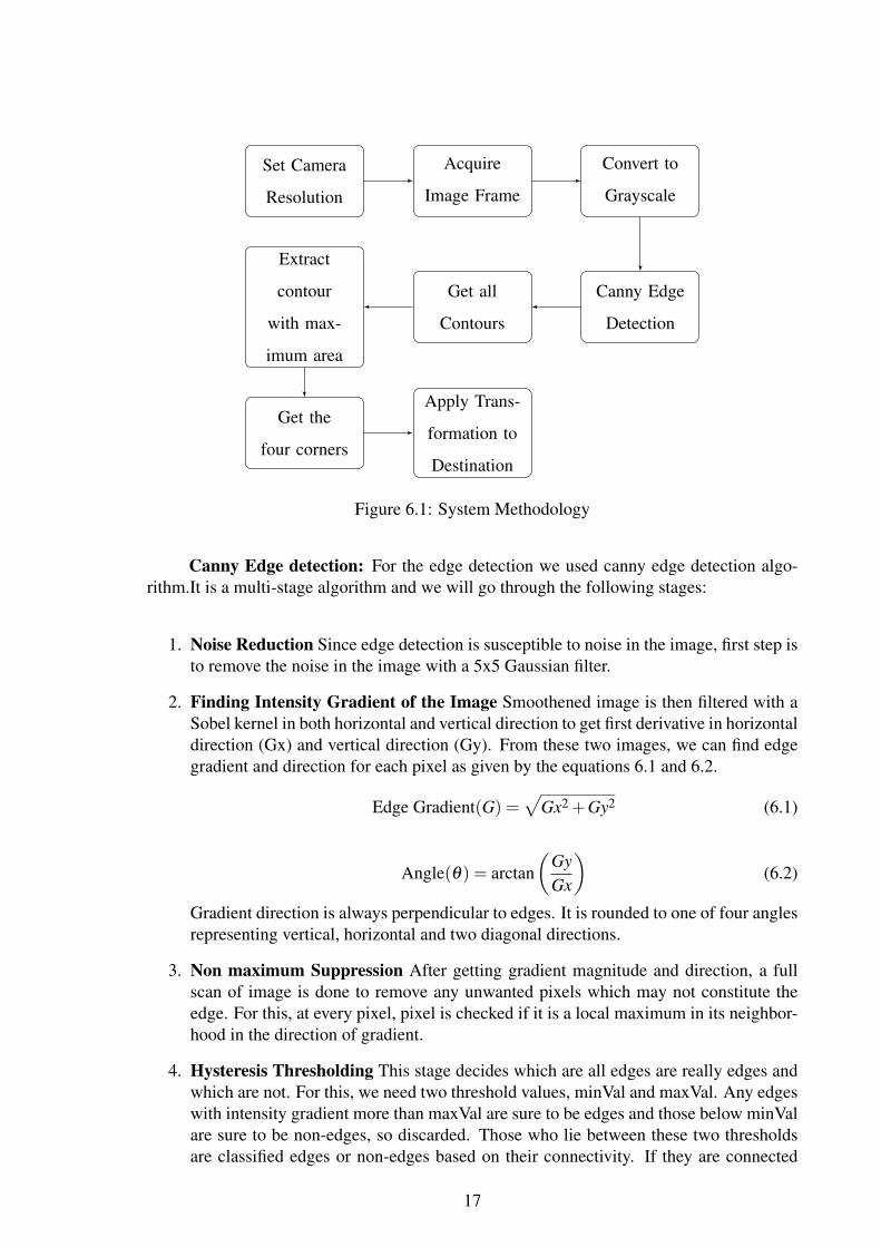
1. Detection of edges to obtain the edge map using Canny edge algorithm
2. Detection of all contours
3. Get parent contour of contour with maximum area
4. Get the four corners of this parent contour
5. Apply the transformation of these corners to a destination coordinates
16
Set Camera
Resolution
Acquire
Image Frame
Convert to
Grayscale
Canny Edge
Detection
Get all
Contours
Extract
contour
with max-
imum area
Get the
four corners
Apply Trans-
formation to
Destination
Figure 6.1: System Methodology
Canny Edge detection: For the edge detection we used canny edge detection algo-rithm.It is a multi-stage algorithm and we will go through the following stages:
1. Noise Reduction Since edge detection is susceptible to noise in the image, first step isto remove the noise in the image with a 5x5 Gaussian filter.
2. Finding Intensity Gradient of the Image Smoothened image is then filtered with aSobel kernel in both horizontal and vertical direction to get first derivative in horizontaldirection (Gx) and vertical direction (Gy). From these two images, we can find edgegradient and direction for each pixel as given by the equations 6.1 and 6.2.
Edge Gradient(G) =√
Gx2 +Gy2 (6.1)
Angle(θ) = arctan(
GyGx
)(6.2)
Gradient direction is always perpendicular to edges. It is rounded to one of four anglesrepresenting vertical, horizontal and two diagonal directions.
3. Non maximum Suppression After getting gradient magnitude and direction, a fullscan of image is done to remove any unwanted pixels which may not constitute theedge. For this, at every pixel, pixel is checked if it is a local maximum in its neighbor-hood in the direction of gradient.
4. Hysteresis Thresholding This stage decides which are all edges are really edges andwhich are not. For this, we need two threshold values, minVal and maxVal. Any edgeswith intensity gradient more than maxVal are sure to be edges and those below minValare sure to be non-edges, so discarded. Those who lie between these two thresholdsare classified edges or non-edges based on their connectivity. If they are connected
17

to sure-edge pixels, they are considered to be part of edges. Otherwise, they are alsodiscarded.
6.2 Detection of Laser Pointer
Since the projected screen can comprise of all sorts of colored imagery, color basedsegmentation method is not appropriate for the detection of laser. For flawless detectionof laser, the exposure of the camera is programmatically reduced so that laser is the onlybrightest pixel seen in the image frame.
6.2.1 Dynamic Exposure Correction
A photograph’s exposure determines how light or dark an image appears when it iscaptured by the camera.
The RPi’s camera is programmable. The camera’s capture property is controlled bythe camera exposure compensation parameter. The exposure correction is done as per thecaptured image’s property dynamically.
The proper exposure configuration improves the detection of the laser. After the pro-jected screen is captured, and the camera exposure values are modified until the laser spot isthe brightest in the input image. On every frame captured, the average of the value channel ofthe image is compared with the preset threshold and the camera exposure level is decreasedaccordingly if the average value of channel is greater than this threshold.
6.2.2 Brightest Pixel Detection
After exposure compensation is done based on the average value of the image captured,the steps involved in detecting the brighest pixel area and its location can be described in thefollowing points:
1. Grayscale conversion Grayscale image carries the intensity information. It is com-posed of shades of gray, varying from black at weakest intensity to white at the strongest.
A RGB image is captured by Rpi at first, which contains all the three components:Red (R), Green (G), Blue (B). The processing of all these components is redundantand time inefficient. The grayscale conversion is done so that the RGB values areexpressed by intensity values within a given range of 0 to 255 values. These grayscalelevels are then thresholded by binary thresholding algorithm. For detail on Rpi Boardand Camera see Appendix D.1, E.1 and F.1.
18

2. Binary Thresholding It is a segmentation method. Thresholding application involvesseparating out regions of an image corresponding to objects which is to be analyzed.This separation is based on the variation of intensity between the object pixels and thebackground pixels.
To differentiate the pixels we are interested in from the rest (which will eventuallybe rejected), we perform a comparison of each pixel intensity value with respect toa threshold (determined according to the problem to solve). Here, we have set thethreshold to be 200 such that regions above this value is thresholded as white and restof the pixels are thresholded as black.
3. Morphological Operations A set of operations that process images based on shapesis termed as morphological operation. Morphological operations apply astructuringelementto an input image and generate an output image.
They have a varied number of uses in the images, such as removing noises, isolation ofindividual elements and joining disparate elements in an image and finding of intensitybumps or holes in an image.
The most basic morphological operations is Dilation. This operations consists of con-voluting an imageAwith some kernel B, which can have any shape or size, usually asquare or circle. The kernel B has a defined anchor point, usually being the center ofthe kernel. As the kernelis scanned over the image, we compute the maximal pixelvalue overlapped byand replace the image pixel in the anchor point position with thatmaximal value. As you can deduce, this maximizing operation causes bright regionswithin an image to grow suppressing the dark ones.
Another morphological operation erosion is the inverse of the dilation process. It com-putes a local minimum over the area of the kernel. As the kernel is scanned over theimage, we compute the minimal pixel value overlapped byand replace the image pixelunder the anchor point with that minimal value. The bright areas of the get thinnerwhereas the dark zones get bigger.
4. Find Contours Contours can be explained simply as a curve joining all the continuouspoints (along the boundary), having same color or intensity. Before finding contours,threshold or canny edge detection should be applied. And it outputs the contours andhierarchy. The outermost contour is taken as laser.
5. Approximate by a bounding rectangle The obtained contour is then approximatedby a bounding rectangle which gives us the x, y coordinates as well as the width andheight of the laser. This is then used to move the mouse pointer.
6.3 Microcontroller to generate laser pulses
An AVR microcontroller is used instead of 555 timer so that resistor and capacitorsvalues need not be changed with the change in frequencies and duty cycles. Below, is theschematic of the system circuit. The laser is turned on when the supply is applied. Whenthe push button is pressed, a pulse at a frequency set to 6Hz in the microcontroller. The
19

proteus simulation of our circuit can be viewed in Appendix G.1 and the schematic diagramin Appendix H.1.
The laser circuit has been programmed such that it produces a 6Hz pulses when thepush button is pressed, else it stays on. The laser hardware eagle design and final circuitscan be viewed in the Appendix I.1, J.1 and K.1. The target frequency has been set to 6Hz.The prescaler used is 64. The top value for pulse width modulation(PWM) is obtained as inthe following equation 6.3.
Top value = (Clock f requency/Target f requency)∗Scaler−1 (6.3)
The top value is 20833. For a 20 per cent duty cycle, the on time of the laser is set to20 per cent of the top value and off time is set to the 80 per cent of the top value. We havekept the push button switch in the interrupt pin, so that when the button is pushed, interruptis obtained and the subsequent Interrupt Service Routine(ISR) can be run. This ISR does thework of producing PWM pulses of 20 per cent duty cycle.
6.4 Hardware Implementation
6.4.1 Laser Wand
A laser wand is the main interacting tool with the vision-based interactive projectorsystem. The laser wand is a custom designed and self fabricated AVR Atmega 8L (pindiagram shown in Appendix L.1 and M.1) microcontroller based system. The input to thewand is a manual button press and outputs from the wand are either continual or varyinglaser blinks.
On continual button press, the blinking of laser wand is made to occur at 6Hz with dutycycle of 20 per cent. Duty cycle is the ratio of on-time of a signal to the total time of a signal.The total time of a signal is the sum of on-time and the off-time of the signal. The on-timeis the window frame of the signal, where the signal is high and off-time is the window frameof the signal, where the signal is low. So a duty cycle of 20 per cent implies that laser is on20 per cent of the time and off 80 per cent of the time when the button is pressed.
6.4.2 Components of Laser Wand
Laser Laser is a device that emits light by optical amplification based on stimulatedemission of electromagnetic radiation. The term LASER is originated as an acronym forLight Amplification by Stimulated Emission of Radiation. Laser light is different from othersources of light because it emits light coherently, thus allowing light to be focused on a tightspot. The laser light being used is of class IIIA, whose power output is 4mW and gives outlight of wavelength 630-680nm.
20
Microcontroller The laser wand is made to blink on manual press of a button. Themicrocontroller has three timers 0, 1, 2 of which 16 bit timer 1 is used in non-inverting PWMmode. The prescaler is set to 64. The Timer and PWM of the avr microcontroller is used toachieve that
6.5 Finalized algorithm for click and drag
We constructed a State Diagram with the three states of laser. Laser-off is a state ofcontinual five or more laser-off states, which occurs when the laser is not detected. Laser-onis a state of continual five or more laser-on states, when the laser is detected. Toggle-0to1occurs when laser state is toggled from off state to on state, whereas in Toggle-1to0, laserstate is toggled from on state to off state.
1. Laser-off or 0
2. Laser-on or 1
3. Toggle 0to1 or 1to0
At all times, when laser is in the on state, the mouse pointer is continually updated tomove. When laser state is toggled, either from laser on to off or vice-versa, the mouse pointeris pressed. If the mouse pointer is moved while in pressed state, drag occurs. This continuesuntil a laser-off state or laser-on state occur, which is interpreted as a mouse release. And,at every toggle state, mouse down occurs and if laser-on or laser-off state is immediatelysucceeded to this event, then mouse is released which is then interpreted as click. The statediagram of the algorithm can be viewd in Appendix N.1 and the final algorithm can beviewed in Appendix O.1
6.6 Communication between computer and RPi
A server and client program are constructed based on TCP protocol. The server andclient maintain the communication between the computer and the RPi. The server programis run on the computer which is being projected by the projector. The client program is runon the RPi which detects laser spots.
Currently, the Looma software is obtaining the mouse coordinates through its serialport from the FPGA board. So we have implemented a protocol for communication us-ing TCP protocol to communicate the mouse actions and coordinates to the computer. TheLooma board is made a server, and the RPi board a client. The client sends the coordinatesof the detected laser spot, and the actions associated with it. Accordingly, the server which is
21

listening to the client, receives the coordinates and their respective actions. The server thensends the actions to the in-built mouse application to do the desired action.
6.7 Movement of Mouse Pointer
The laser coordinates, x and y, detected by the RPi camera is mapped to the systemcoordinates.
First of all, a point obtained in the image window width of 640 and height of 480, istranslated to the origin of the image coordinates system using the following equations 6.4and 6.5.
x′ = x− tx (6.4)
y′ = y− ty (6.5)
where tx and ty are the translation factors.
Now, the obtained point in the origin of the image window is scaled as per the scalingfactor obtained as below:
A point at position (xw,yw) in the image window is mapped into position (xv,yv) inthe viewport of system. To maintain the same relative placement in the viewport as in thewindow, we require that
(xv− xvmin)/(xvmaxxvmin) = (xwxwmin)/(xwmaxxwmin) (6.6)
which gives the scaling factores in x and y directions as,
sx = (xvmaxxvmin)/(xwmaxxwmin) (6.7)
sy = (yvmaxyvmin)/(ywmaxywmin) (6.8)
where, sx and sy are the scaling factors [4] The vmax and vmin are the maximum andminimum coordinates of the viewport system whereas wmax and wmin are the maximumand minimun coordinates of the image window. The corresponding scaling factors are mul-tiplied to the translated image window coordinate and then re-translated using the followingequations.
x′ = x+ tx (6.9)
22

y′ = y+ ty (6.10)
where tx and ty are the translation factors. The final coordinates obtained is used tomove the mouse pointer on the Looma system.
23

7 PROBLEM FACED and SOLUTIONS
7.1 Laser Hardware
Initially, in an attempt to reduce the costs of the overall laser hardware, we had at-tempted to pulse the laser led using 555 timer circuits. The 555 timer circuits comprisedof resistors and capacitors which were picked up precisely enough to give us the requiredfrequency. However, continual error checking and correction, for the detection of the pulsedlaser led by camera, the resistors and capacitors had to be changed frequently, which provedto be inefficient and tedious.
Despite the cost constraints, we moved on to Atmega 8L microcontrolle. We wouldhave used an ATTiny45 microcontroller, which is about the same size as a 555 timer, but itwas not readily available. Thereby, we programmatically pulsed our laser led, as required.Thus, it was easy to setup the laser hardware for the detection system. In the end, we designedand fabricated the hardware, based on Atmega 8L microcontroller.
7.2 Detection of laser point by HSV Segmentation
HSV is Hue, Saturation and Value of an image. HSV Segmentation deals with thenatural color of the object to be detected. We tried to detect the laser utilizing its distinctintensity value in the red region. However, the detection failed in cases when other pointswith same color and intensity came on the projected screen.
For resolving the problem, we considered only the brightest pixels in the projectedscreen. However, along with the laser pointer, other bright parts of the view port such as thewhite parts of the projection itself, and other bright reflections were also being captured. Sowe programmatically checked the intensity of lights reaching the camera’s aperture, and ifit exceeded a calibrated level, we reduced the shutter time thereby only allowing minimalexposure to the image. It was found that, laser was seen to be the brightest spot amongall pixels. So, an exposure correction of the camera was carried out before the start of thedetection. This ensured that only the bright laser pointer is detected.
7.3 Slow detection and action by RPi
Initially, the captured frame size was 640*480 in which we observed a time lag betweenthe instance the laser moved on the screen and the movement of the laser pointer in theLooma system. This made it difficult to interact with the system. A larger image resolutionhad been chosen to detect the laser center from any distances. Since the brightest center of
24

the laser point is reduced in size in the image captured as the detection system is kept furtheraway from the Looma system.
To solve this, we reduced the frame size to 320*240 which is half of our previousframe size. As mentioned above, the size of the laser spot captured by the camera was smallcompared to the above case. Therefore, the dilation algorithm was implemented which madethe brighter regions become bigger. As our laser pointer is also the brighter region, it dilatessuppressing the other darker regions around it.
The erosion algorithm was applied to the image obtained after the dilation which madethe bright regions get thinner and makes the laser pointer more distinct irrespective of thepresence of other noises. The processing speed was faster due to the fast processing ofsmaller sized frames.
25
8 RESULTS AND ANALYSIS
8.1 Hardware Testing
This phase of the hardware testing includes the following tests:
1. Connectivity testing
2. Cold solder testing
3. Checking the polarity of the capacitors
4. Testing the response of button and microcontroller
8.1.1 Testing the Laser Circuit
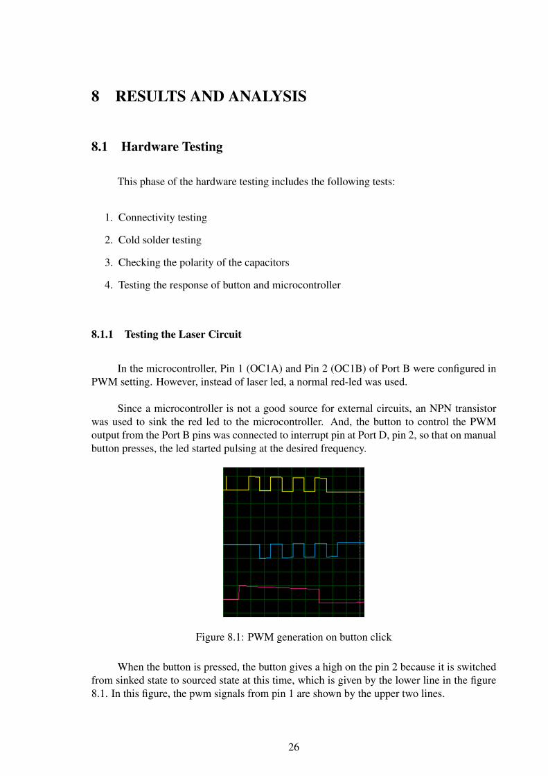
In the microcontroller, Pin 1 (OC1A) and Pin 2 (OC1B) of Port B were configured inPWM setting. However, instead of laser led, a normal red-led was used.
Since a microcontroller is not a good source for external circuits, an NPN transistorwas used to sink the red led to the microcontroller. And, the button to control the PWMoutput from the Port B pins was connected to interrupt pin at Port D, pin 2, so that on manualbutton presses, the led started pulsing at the desired frequency.
Figure 8.1: PWM generation on button click
When the button is pressed, the button gives a high on the pin 2 because it is switchedfrom sinked state to sourced state at this time, which is given by the lower line in the figure8.1. In this figure, the pwm signals from pin 1 are shown by the upper two lines.
26

8.2 Software Testing
8.2.1 Algorithm Test
In normal clock mode, a raspberry had a clock frequency of 700MHz, therefore ageneral laptop with a clock frequency of over 1 GHz, has a better computing power. Beforeall the hardwares were made available to us, we initially, tested our laser detection algorithmson our computer. The inbuilt webcam or even a cheap USB webcam used with the computerdo not have the programmatic exposure correction features, which RPi camera had. For thepurpose of testing, we used a darkly lit room and less bright projected screen for the detectionof the laser point. It was observed that the algorithm performed well and the mouse downand releases were achieved in almost real time.
Later, the algorithm was tested on Rpi by programmatically setting the exposure. Theprojected screen before programmatic exposure correction is given by in the top left windownamed Thresh in the image shown in the Appendix P.1. This window named Thresh isshowing the projected screen as seen by the Rpi camera. After the exposure correctionis done, only the laser pointer is the visible white dot in the window named Thresh. Theexposure corrected image in the window Thresh can be viewed in the Appendix Q.1. Sincethe algorithm worked on both the Rpi and on our computer, the algorithm test was a success.
8.2.2 System Test
The laser detection algorithm was tested on RPi. For the communication of the de-tection system and the computer, a client server architecture was implemented where RPi,being the client and the Loomas existing Pandaboard, running as the server. In this way, thetesting was carried out.
RPi’s processor is not capable of processing real time video at 24 fps. It was observedthat at maximum, it processes the video at about four fps. Thereby, it hindered the laserdetection algorithm significantly. The laser on-offs were not seen as the expected by thealgorithm and the processing is found to be slower than in computer.
To improve the overall detection of the laser pointer, we reduced the image frames byhalf and did dilation on the image to enlarge the pixels. This improved the detection by asignificant amount but with some errors since it dilated non-laser spots as well. Hence, asmentioned in the problems faced and solutions section, the overall detection and actions arenot performed in real time by due to slow processor and other bright spots in the projectedscreen. Since both the systems, Rpi and a general computer, could detect the laser spot andperform actions, the system test was a success as well.
27

9 COST ANALYSIS
9.1 Cost Comparison between Looma System and Our System
S.N Existing System Cost Designed System Cost
1 FPGA Board and Wiring $117 RPi $64.90
2 Nintendo Wii Remote $68.89 RPi Camera Module $29.95
3 3D Printed IR Wands $20 Laser Pointer $0.9
4 Atmega8L $1.87
Total $205.89 Total $97.62
Table 9.1: Cost Comparison between Existing System and Our System
Since Looma system is intended for the rural areas, the system needs to be as economicas possible. From the table 9.1, it can be inferred that, the system that we have designed ischeaper as compared to the existing system of Looma. Also, the overall cost of our projectcan be viewed in the table 9.2.
28

9.2 Total Cost of Our Project
S.N Items Rate(Rs) Quantity Total(Rs)
1 Hydrogen Peroxide 30 1 30
2 Soldering Rod Bit(40W) 250 1 250
3 Capacitors 10 2 20
4 Push Button Switch 5 1 5
5 12 Mhz Crystal 35 1 35
6 IC Base 10 2 20
7 Transistor 35 1 35
8 Drill Bit 20 1 20
9 PCB 300 1 300
10 Laser 90 1 90
11 Conc. HCl(250ml) 500 1 500
12 Aceton(250ml) 300 1 300
13 Atmega8L 180 1 180
14 RPi 6380.319 1 6,380.319
15 RPi Camera Module 2,944.3845 1 2944.3845
16 Laser Pointer 0.9 1 88.479
17 Atmega8L 183.8397 1 183.8397
18 Documentation 4000 1 4000
19 Battery Pack 200 1 200
20 Battery Holder 50 1 50
Total 22 15,443.5432
Table 9.2: Total Cost of Our Project
29
10 LIMITATIONS AND FUTURE ENHANCEMENTS
10.1 Limitations
1. Due to the slow processing speed of the RPi used, there is lag in the overall system.
2. This system may not respond well under bright light conditions.
3. Since the RPi camera is not permanently fixed to the system, a slight movementchanges the calibration data of the system.
10.2 Enhancements
1. A proper hardware with the RPi system fixed inside Looma can prevent the system tobe re-calibrated each time it is moved during use.
2. A better processor than the RPi can be used to enhance the systems speed and effi-ciency, allowing it to perform real time operations.
3. The system performs single clicks and drag as required by the Looma system, but withfurther enhancements, it can be made to perform double clicks.
30

11 CONCLUSION
11.1 Conclusion
The project Laser Pointer based Human Computer Interaction using Computer Visionaims to provide an alternative solution to the interactive wand system developed by Looma.The system that we have designed allows the user to control the projected system from aconsiderable distance using the laser pointer. This aids in the teaching process and makesthe audio visual learning environment more interactive. Although initially, the system hadbeen designed to work on Looma system but we have tried to make it as generic as possibleand can be used for other projector systems as well.
The system emphasizes on the algorithms for the detection of laser pointer on thescreen and implementation of click and drag operations. By integrating the algorithm withthe proper laser hardware, the required laser pointer based interaction system has been devel-oped successfully. The system has been tested in the real working environment. Although,the system can not process real-time data due to the low processing power of the Rpi pro-cessor, the required main actions are performed efficiently. With enhancements suggestedabove, the system’s accuracy and speed can be increased considerably.
During the process of development, many research works carried out in the respectivefields were thoroughly studied. Based on the results and conclusions of these papers, thealgorithms that best suited the domain of this project was selected and their citations can beviewed in the references.
31
REFERENCES
[1] Kirstein and Muller, Interaction with a Projection Screen Using a Camera-Tracked LaserPointer,University of Dortmund, Germany
[2] Johnny Chung Lee, Hacking the Nintendo Wii Remote, Carnegie Mellon University,IEEE-CS,2008
[3] Rafael C. Gonzalez and Richard E. Woods, Digital Image Processing, 3rd Edition
[4] Donald Hearn and M. Pauline Baker, Computer Graphics C Version, 2nd Edition
32

APPENDIX A TCP PROTOCOL
Socket()
Bind()
Listen() Socket()
Accept()
Block until there
are connections
from client
Connect()
Read() Write()
Write() Read()
Close() Close()
Connection Established
Data(Request)
Data(Reply)
Figure A.1: Transmission Control Protocol between Server and Client
33

APPENDIX B CAMERA MOUNT
Figure B.1: Custom Camera Mount
34

APPENDIX C RPi AMOUNT LOOMA
Figure C.1: RPi amount looma hardware
35

APPENDIX D RPi AND CAMERA BOARD
RPi is a single-board computer with processor, memory, I/O ports and many morefeatures, which together make it a functional computer for a wide range of applicationsin robotics. It is so simple than any logical person can program it, even it is for the firsttime when you work with a single-board computer.The ARM powered minicomputer is aplatform with enormous possibilities and powerful enough to run many of the same programsas computer.
RPi serves as a wonderful platform for computer vision algorithms given its size, won-derful camera board and portability. Using the Picamera module, we took raw byte streamsof the projected screen, and converted them to OpenCV object before doing further imageprocessing algorithms. RPi Camera Board Module supports a full HD (High Definition)video streaming at fps of 30 with its 5 megapixel native resolution, and the sensor capableof 2592-1944 pixel static images. RPi Camera Board Module was opted instead of normalUSB web camera.
The software of RPi (RPi) utilizes Rpi GPU (Graphical Processor Unit) when usingRaspi Camera Module. So for example encoding h.264, video has low impact on the CPU(Central Processor Unit) usage. Also, it has an excellent resolution of 5 Megapixels, whichis higher than most USB webcams. It also has an excellent daytime image quality. If we useUSB Webcam, it will have a very slow frame rate video and the CPU usage will be quitehigh. RPi does not have enough CPU horsepower to do higher frame rates, resolution andadvanced video compression.
36

APPENDIX E RPi BOARD
Figure E.1: RPi Board
37

APPENDIX F RPi CAMERA MODULE
Figure F.1: RPi Camera Module
38

APPENDIX G SIMULATION OF LASER HARDWARE
Figure G.1: Laser Hardware Simulation
39

APPENDIX H LASER CIRCUIT SCHEMATIC
Figure H.1: Laser circuit schematic
40
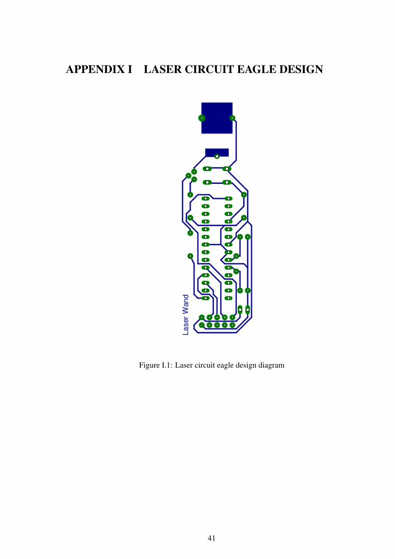
APPENDIX I LASER CIRCUIT EAGLE DESIGN
Figure I.1: Laser circuit eagle design diagram
41

APPENDIX J FINAL LASER HARDWARE
Figure J.1: Final Laser Hardware
42

APPENDIX K FABRICATED LASER CIRCUIT
Figure K.1: Laser circuit fabricated design
43

APPENDIX L AVR ATMEGA 8L FEATURES
1. High-performance, Low-power Atmel AVR 8-bit Microcontroller
(a) Advanced Reduced Instruction Set Computer (RISC) Architecture
(b) 130 Powerful Instructions Most Single-clock Cycle Execution
(c) 32 8 General Purpose Working Registers
2. High Endurance Non-volatile Memory segments
(a) 8Kbytes of In-System Self-programmable Flash program memory
(b) 512Bytes EEPROM
(c) WriteErase Cycles: 10,000 Flash. 100,000 Electrically Erasable ProgrammableRead Only Memory (EEPROM)
(d) Data retention: 20 years at 85oC 100 years at 25oC
3. Peripheral Features
(a) Two 8-bit Timer/Counters with Separate Prescaler, one Compare Mode
(b) One 16-bit Timer/Counter with Separate Prescaler, Compare Mode, and CaptureMode
(c) Real Time Counter with Separate Oscillator
(d) Three PWM Channels
4. Operating Voltages
(a) 2.7V - 5.5V (ATmega8L)
(b) 4.5V - 5.5V (ATmega8)
5. Speed Grades
(a) 0 - 8MHz (ATmega8L)
(b) 0 - 16MHz (ATmega8)
6. Power Consumption at 4Mhz, 3V, 25oC
(a) Active: 3.6mA
(b) Idle Mode: 1.0mA
44

APPENDIX M AVR ATMEGA8L PIN DIAGRAM
Figure M.1: AVR Atmega8L Pin Diagram
45

APPENDIX N STATE DIAGRAM
1to0
0
0to1
1
00000
0
100000
1
0
11111
1
11111
0
Figure N.1: State Diagram
46

APPENDIX O FLOWCHART OF THE ALGORITHM
Start
Grab Image
Frame
Calibrated?
While
User Not
Exit?
Grab New
Frame
Laser
Detect?A
Mouse
Down?
Send
”Mouse
Move”
to Server
Send
”Mouse
Release”
to Server
Stop
Blink
Continual
Yes
Yes
Yes
No
No
Figure O.1: Flowchart of the algorithm
47

A
Action
Detect?
Send ”Mouse
Down” to Server
Send ”Mouse
Down and
Release”
to Server
Blinks < 3
No
Figure O.2: Flowchart of the algorithm
48

APPENDIX P BEFORE EXPOSURE CORRECTION
Figure P.1: Projected Screen Before Exposure Correction
49

APPENDIX Q AFTER EXPOSURE CORRECTION
Figure Q.1: Projected Screen After Exposure Correction
50