treetop circuits owner’s manual for sb-390 ssb adapter ... · treetop circuits owner’s manual...
TRANSCRIPT
Treetop Circuits
Owner’s Manual for SB-390 SSB Adapter
Version 5
1
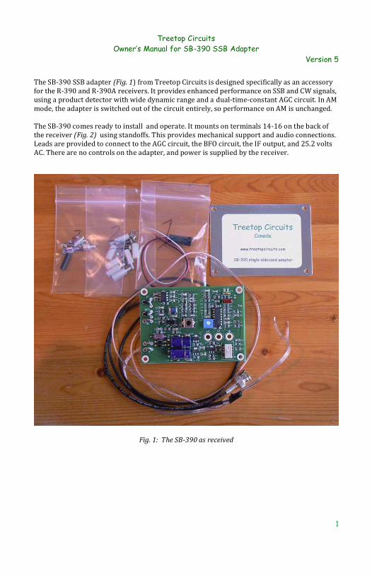
The SB-390 SSB adapter (Fig. 1) from Treetop Circuits is designed specifically as an accessory for the R-390 and R-390A receivers. It provides enhanced performance on SSB and CW signals, using a product detector with wide dynamic range and a dual-time-constant AGC circuit. In AM mode, the adapter is switched out of the circuit entirely, so performance on AM is unchanged. The SB-390 comes ready to install and operate. It mounts on terminals 14-16 on the back of the receiver (Fig. 2) using standoffs. This provides mechanical support and audio connections. Leads are provided to connect to the AGC circuit, the BFO circuit, the IF output, and 25.2 volts AC. There are no controls on the adapter, and power is supplied by the receiver.
Fig. 1: The SB-390 as received
Treetop Circuits
Owner’s Manual for SB-390 SSB Adapter
Version 5
2
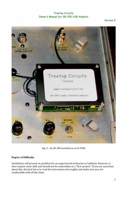
Fig. 2: An SB-390 installed on an R-390A Degree of Difficulty Installation will present no problem for an experienced technician or hobbyist. However, it does require some skill, and should not be undertaken as a “first project”. If you are uncertain about this, the best bet is to read the instructions thoroughly and make sure you are comfortable with all the steps.
Treetop Circuits
Owner’s Manual for SB-390 SSB Adapter
Version 5
3
You should have the manual for your receiver available. You will need to remove and reinstall the IF subchassis, and readjust the BFO center frequency, according to the manual. The small parts required for installation are in numbered bags. Making the connections to the IF module in the receiver (Part 1 of the installation) requires the most skill. Some owners may prefer to have someone with more experience undertake this part of the job. Connectors are provided so that only the IF module and bag 1 need to be shipped or transported. Treetop Circuits can provide clarification on specific points, so please do not hesitate to e-mail. But please also bear in mind that there is no substitute for basic electronic skills and good workmanship. And as always, remember that lethal voltages are present in this receiver. Modifications by Owner Some owners will want to experiment with the circuit. To facilitate this extra holes are provided near the AGC time-constant capacitors C10 and C11. Please read the section on warranty before modifying the circuit. Before Proceeding We recommend that you check our web page http://treetopcircuits.com/docs to be sure you have the latest version of this manual. Do not hesitate to email us at [email protected] if you need assistance. Like all semiconductor circuits, the SB-390 can be damaged by electrostatic discharge. Appropriate practices should be used when handling it. If the receiver chassis is not connected to ground, the resulting “ground buzz” can (rarely) damage the SP-390 if the circuit finds a ground path. This situation should never occur; for safety reasons, the chassis should always be grounded, either independently or through a three-wire line cord. Preparing the Radio The radio should be in good operating condition and properly aligned. If this is not the case, it is recommended that a performance check and alignment be performed before proceeding. Since the SB-390 depends on IF and BFO signals derived from the receiver, it is particularly important that these are correct. In some radios, the center contact of the IF connector has become oxidized and will not make contact. A paper clip with metal polish has been used successfully to remove this oxide film. A shot of DeOxit is a good idea in any event. Installation Unplug the receiver from the power source. Do not trust the switch. 1. Open Bag 1. It contains a connector with three wires attached, which is to be installed to bring the BFO and 25.2 VAC connection to the top of the subchassis..

Treetop Circuits
Owner’s Manual for SB-390 SSB Adapter
Version 5
4
Fig. 3: Connections under the IF subchassis of an R-390A. The bellows has been removed, and the
red, white, and black wires are indicated. You will need to access both top and bottom of the IF subchassis (Fig. 3). Remove the IF module completely, or just turn it over. Remove the bellows joining the BFO control shaft to the PTO, and the BFO shaft, using a .096" Bristol wrench (DO NOT try to do this with an Allen key, etc.). The "C" clip on the BFO shaft does not normally have to be removed. Don't worry about maintaining the alignment of the pointer on the knob; you will have to readjust this after installation. Feed the wires through the hole beside the GAIN ADJ and CARRIER-METER ADJ pots, and connect as follows:
In an R-390: Connect the red wire to RT512, pin 2. This is the AC power connection. Remove C536. This is the small capacitor between V508, pin 5, and V507, pins 1 and 2. Do not change the other connections on V507. Connect the white lead to V508, pin 5. In an R-390A: Connect the red wire to RT510, pin 2. This is the AC power connection. Remove C535. This is the small capacitor between V505, pin 5, and V506, pins 6 and 7. Do not change the other connections on V506. Connect the white lead to V505, pin 5.
Treetop Circuits
Owner’s Manual for SB-390 SSB Adapter
Version 5
5
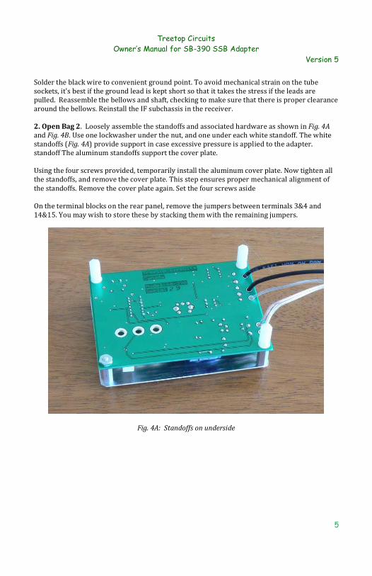
Solder the black wire to convenient ground point. To avoid mechanical strain on the tube sockets, it's best if the ground lead is kept short so that it takes the stress if the leads are pulled. Reassemble the bellows and shaft, checking to make sure that there is proper clearance around the bellows. Reinstall the IF subchassis in the receiver. 2. Open Bag 2. Loosely assemble the standoffs and associated hardware as shown in Fig. 4A and Fig. 4B. Use one lockwasher under the nut, and one under each white standoff. The white standoffs (Fig. 4A) provide support in case excessive pressure is applied to the adapter. standoff The aluminum standoffs support the cover plate. Using the four screws provided, temporarily install the aluminum cover plate. Now tighten all the standoffs, and remove the cover plate. This step ensures proper mechanical alignment of the standoffs. Remove the cover plate again. Set the four screws aside On the terminal blocks on the rear panel, remove the jumpers between terminals 3&4 and 14&15. You may wish to store these by stacking them with the remaining jumpers.
Fig. 4A: Standoffs on underside

Treetop Circuits
Owner’s Manual for SB-390 SSB Adapter
Version 5
6
Fig. 4B: Standoffs and cover on top side 3. Open Bag 3. Remove the screws from terminals 14, 15, and 16. Replace these with the 3 short standoffs and 3 lockwashers. Tighten the standoffs snugly with a 1/4" nutdriver or other tool. These standoffs are aluminum, so avoid over-torquing them. Position the adapter so that three large mounting holes (marked 14, 15, and 16) line up with the standoffs and fasten the adapter in place using three short screws and lockwashers (Fig. 2). Assemble them all loosely, align the adapter with the panel, then tighten the screws. You should feel the lockwashers compress, but don't over-torque. You want the lockwashers to bite, but there's no need to flatten them. Locate the paired wires connected to the pads marked 3 and 4 near the left edge of the adapter. These go to terminals 3 and 4 on the terminal block respectively, and provide the necessary connections to the AGC section. Cut the wires to length, if necessary. Separate them for about 2", and slide a piece of shrink tubing onto each wire. Strip the wires and crimp and solder the terminals onto them. Crimp the terminals onto the insulation, and position and shrink the tubing using a hot-air gun or soldering iron (hold the iron close to, but not touching, the tubing). Connect the terminals to the terminal strip. Note that the wire for terminal 4 has a silver conductor (or a white marker in some units). The BFO and 25.2 VAC signals are connected to the black three-point connector. Thread the connector, and the wires, through the SYNC access hole in the back panel (Fig. 2). Align the

Treetop Circuits
Owner’s Manual for SB-390 SSB Adapter
Version 5
7
black connectors, and push until they latch. If you want to disconnect them, press the small corrugated lever and they will separate easily. Connect the BNC connector to the IF output jack on the rear panel. Install the cover plate, using four screws and lockwashers. If you choose to operate the receiver without the cover plate, be aware that the BFO anode voltage is present on some of the circuitry. Operation The installation is now complete and the receiver is ready to operate. All controls should function as before, except that: a) The AGC time-constant switch will not function in CW/SSB mode. The time constant is controlled by the adapter. b) The MGC function will not work in CW/SSB mode. The AGC will remain functional at all times in this mode. The RF gain control will continue to act normally. c) Noise limiter operation may not be satisfactory in CW/SSB mode because the noise limiter is designed for AM. The audio gain potentiometer (R11) should not need adjustment. However, you may want to adjust it so the audio level in SSB is reasonably close to that in AM. If you decide to make adjustments, note the position of the potentiometer so you can return to the "factory" settings. Also, if you set the gain too high, clipping may occur on strong signals. The BFO may be a bit off frequency due to the loading effect of the coax cable. We recommend that you align the BFO so that the frequency is in the center of the mechanical filter passband with the knob at "0" (the procedure in the receiver manual will accomplish this). For best SSB reception, the BFO frequency should be just off the shoulder of the IF passband; this is particularly critical with mechanical filters because of their steep skirts. The BFO pitch control should therefore be offset from zero by roughly half the filter bandwidth. In these receivers, the signal is inverted in the second mixer and again in the third mixer, so it appears at the detector in non-inverted form. Therefore, use a "-" setting for USB and a "+" setting for LSB on all bands. The above settings establish a starting point. Due to filter aging and other factors, the exact settings for your receiver must be found by experiment. In SSB operation, the nominal frequency is the frequency on which the carrier would appear if it were present. Once the correct BFO setting has been established, you can make the frequency indicator read correctly by performing the frequency calibration at the nearest 100 kHz point in the usual manner, but with the BFO offset for SSB reception. You will find that you no longer need to "ride" the RF gain control. It can be left wide open on all but the strongest signals. Notes on problems encountered and suggestions from customers will appear on our website shortly. Go to www.treetopcircuits.com and click on Technical Notes.

Treetop Circuits
Owner’s Manual for SB-390 SSB Adapter
Version 5
8
Circuit Description (Fig. 5) In the following circuit description, it is assumed that the schematic diagram for the receiver is available for reference. To understand the operation of the adapter, it is helpful to begin with the BFO and mode switching circuitry. In AM mode (BFO off), relay K1 is not operated. Terminals 3 and 4 are thus connected together by the relay NC contacts, as are terminals 14 and 15. This emulates the connections made by the jumpers which were removed during installation, so operation of the receiver in AM mode is unaffected by the presence of the SB-390. When the BFO is turned on, the 455kHZ (+/-) signal appearing at the BFO tube plate is coupled through C14 to the limiting amplifier consisting of Q3, Q4, and associated components. The signal appearing at the collector of Q3 is rectified and filtered. The resulting DC voltage drives operational amplifier U2A, which acts as a comparator and relay driver. Relay K1 operates, allowing the adapter circuitry to take over the detector and AGC functions. The adapter is now in SSB mode. The BFO signal also appears at the collector of Q4, and is coupled via C1 to a resonant circuit consisting of C5, L2, and C6. Because of the resonant action, the voltages at the ends of L1 are 180 degrees out of phase, causing all four switching diodes D1-D4 to conduct during one half cycle and not conduct during the alternate half cycle. The net effect is that the junction of D1 and D2 is grounded during alternate half cycles. The IF signal is amplified by U1. The signal path from U1 through R7, C9, and R8 is shorted to ground on alternate half-cycles of the BFO signal as described above, so a difference signal (the recovered audio) appears. The IF and BFO components are filtered out by R8 and C2, leaving the recovered audio to be amplified by U2D and applied via contacts on relay K1 to the receiver audio circuits (terminal 15). The IF signal at the output of U1 is also applied to the AGC rectifier consisting of D5, D6, and associated components. The resulting positive DC voltage is amplified and inverted by U2C, which is also pre-biased through R30 to establish the AGC threshold. The AGC time-constant circuit is driven via R20 and D10. A dual-time-constant configuration consisting of R21, C10, R22, and C11 is used to provide good audio level control together with a high resistance to blocking on noise bursts. R32 and R33 provide a small pre-bias to speed up re-sensitization when a strong signal disappears, as at the end of a transmission. Operational amplifier U2B is connected as a non-inverting amplifier. It presents a high impedance to the time-constant circuit. The output of U2B drives the receiver AGC line (terminal 4) via contacts on K1. Diode D7 disables the AGC circuits when in AM mode to prevent a dead period during mode switching. Q5 and associated components apply a load to the Diode Load line when in SSB mode to prevent possible audio clicks during mode switching.

Treetop Circuits
Owner’s Manual for SB-390 SSB Adapter
Version 5
9
AC power is derived from the receiver and rectified by D13 and D14, and filtered by C15 and C7. Q1, Q2, and associated circuits regulate the resulting DC, providing approximately +/- 15 volts to power the SB-390 circuits. Terminal 16 is the main ground connection.
Fig. 5: Circuit Diagram Warranty and Return Policy If you are not satisfied with the product for any reason, you can ship it back to us. Provided that it is shipped within 30 days of your receiving it, and we receive it in good shape, we will

Treetop Circuits
Owner’s Manual for SB-390 SSB Adapter
Version 5
10
credit your PayPal account with the amount you paid us – that is, full purchase price including shipping one way. If the product fails in normal use within one year from when you received it, return it to us at your expense. We will repair it and ship it back to you at no charge or replace it (our option).“Normal use” means that it is installed in a correctly functioning R-390 or R-390A receiver, according to the instructions provided and using good workmanship. Also, we will not be responsible for damage caused by receiver malfunction or other events beyond our control, including (but not limited to) power surges and lightning hits. Non-warranty repairs will be carried out for a flat fee of $20 U.S. plus shipping both ways. We reserve the right to refuse to repair heavily damaged units under this policy. If you ship the unit, use an anti-static bag like the one it came in, or wrap it in aluminum foil, to protect it from static electricity generated by packing material. You can modify the unit without automatically voiding the warranty. We make this provision so that knowledgeable owners can alter the AGC time constants and other properties according to individual preferences. However, if you return such a unit for repair, you must tell us in detail what changes were made, the workmanship must be good (in our judgment), and we have the final word on whether your actions caused the failure.
73,
Bob Thomas VE3TOU
Owner, Treetop Circuits