transnet regenerative braking concept definition
TRANSCRIPT
page 1 of 14
Transnet regenerat ive braking concept
def in i t ion
Achmed Giesler CSIR
Copyright © 2014 by A Giesler. Published and used by INCOSE with permission.
Abstract.Transnet has shown an interest in the concept of regenerative braking on their freight trains. Regenerative braking is the capturing, storing and re-using energy currently being wasted during regenerative braking. Currently all the energy is dumped into a rheostat where it is converted into heat. Storing this energy either on the train or off the train and re-use it during acceleration could have significant cost and other advantages. The CSIR has fields of expertise that could be useful in developing such a system. Super capacitors, Li-ion battery technology, simulation and battery pack controllers are a few technologies that could be used in developing a solution. This Concept Definition is for a Transnet regenerative braking project on their freight lines. Transnet has two main freight lines that carry large amounts of freight: the Sishen-Saldanha and the Ermelo to Vryheid-Oos rail lines. The CSIR main focus is on research and new technology development, while Transnet’s focus is on quality service to the client, which includes value for money. These expectations need to be managed carefully to achieve a win-win situation for both parties. Hence the need for a system engineering approach to keep this project on track and focused on meeting the needs of Transnet.
Introduction
This document describes part of the work that goes towards the Concept Definition for a Transnet regenerative braking project. Transnet has a interest for a regenerative braking energy storage and retrieval system for the Sishen-Saldanha and the Ermelo to Vryheid-Oos rail lines. The CSIR launched a project to investigate the concept and associated technologies that could be used for storing and re-using energy currently wasted during regenerative braking. Currently all the energy is dumped into a rheostat where it is converted into heat. Storing this energy either on the train or off the train and re-use it during acceleration has a number of advantages e.g. reduced power consumption. CSIR has fields of expertise that could be useful in developing such a system. Super capacitors, Li-ion battery technology, simulation and battery pack controllers are a few technologies that could be used in developing a solution.
Scope
Firstly, a more detailed look of the scope of this paper and a few system engineering definitions. System engineering is generally an unknown concept with non-engineering researchers and managers. The International Council of System Engineers (INCOSE) defines system engineering as:
Is an interdisciplinary approach and means to enable the realization of successful systems.
page 2 of 14
Focuses on defining customer needs and required functionality early in the development cycle, documenting requirements, and then proceeding with design synthesis and system validation while considering the complete (lifecycle) problem (operations, cost and schedule, performance, training and support, test, manufacturing, and disposal).
Considers both the business and the technical needs of all customers with the goal of providing a quality product that meets the user needs.
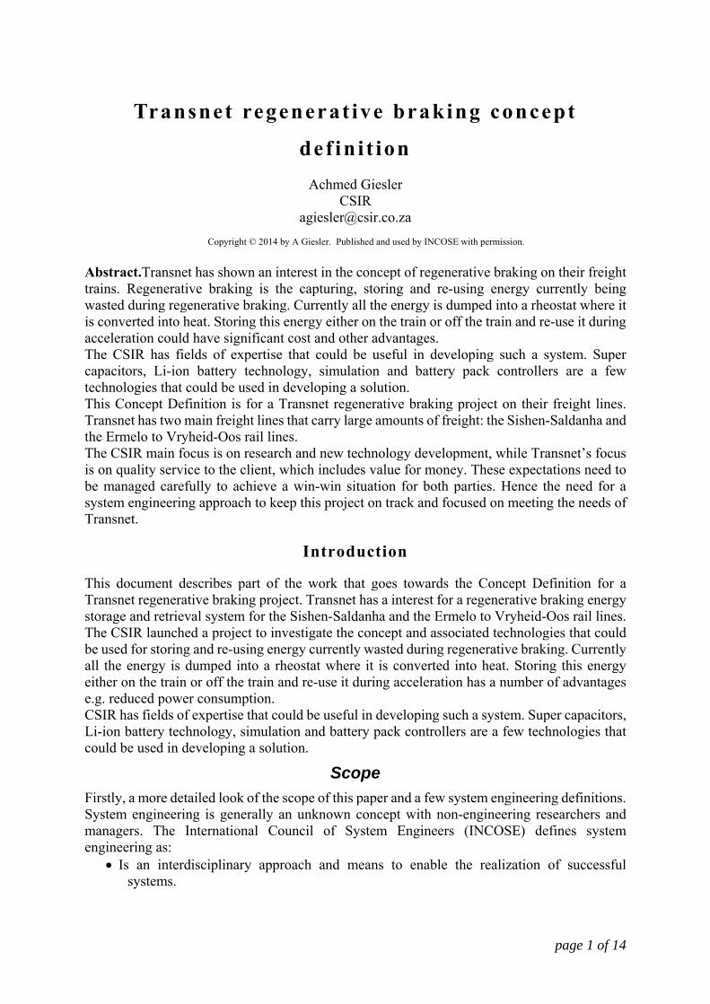
A life cycle model for a system identifies the major stages that the system goes through, from its inception to its retirement (Life Cycle Models, 2014). The aim is that at the end of each stage there is a gate where stakeholders decide whether to proceed to the next stage (or stay in the current stage or terminate the project). A generic lifecycle model is depicted in Figure 1 below. This is merely to illustrate a broad overview of the system engineering life cycle process as each lifecycle should be tailored to the specific project situation.
Figure 1: A Generic Lifecycle Model (Life Cycle Models, 2014) The first phase is the definition phase, the focus area of this document. The System Engineering Body of Knowledge (SEBOK) (Concept Definition, 2014) defines the concept definition as the set of systems engineering (SE) activities in which the problem space and the needs and requirements of the business are examined under the following two primary activities:
Mission Analysis Activity Stakeholder Needs and Requirements Activity
The mission analysis activity examines the needs and requirements of the business. It defines the problem (or opportunity in this case) that exists as well as investigating the constraints and boundaries of the proposed system, in this case regenerative braking energy storage and retrieval. The stakeholder needs and requirements activity examines the operational aspect of a potential solution for the stakeholders, independent of any specific solution. The purpose of this document is to focus on the problem space and not the solution space. In other words, it aims to explore and define the problem (or improvement in this case), what is should accomplish and why it is needed. It does not look at how the improvement will be addressed (the solution). However, as a following step in the concept exploration, alternative solutions should be identified and traded off against each other and against the stakeholder requirements.
Rationale
This project is still in the exploratory stage, with a possibility of much research and development that might be required and it can be argued that a concept definition might be premature at this this. However, this concept definition aims to serve as a framework and to provide a base that can be used for future collaboration, research and development. The aim of this concept definition is not purely research with the aim to develop intellectual property such as patents, but also to guide a team of researchers from various fields of expertise to develop a demonstrator for a possible regenerative braking system solution. The CSIR is looking at developing new technologies with possible patents, licenses and research papers. The researchers are looking for opportunities for new inventions, new designs
page 3 of 14
and novel solutions. The CSIR mandate as stipulated in the Scientific Research Council Acts states the following objects: “The objects of the CSIR are, through directed and particularly multidisciplinary research and technological innovation, to foster, in the national interest and in fields which in its opinion should receive preference, industrial and scientific development, either by itself or in co-operation with principals from the private or public sectors, and thereby to contribute to the improvement of the quality of life of the people of the Republic, and to perform any other functions that may be assigned to the CSIR by or under this Act.” (The Scientific Research Council Act no 46 of 1988 as amended by Act 71/1990, 1900). Transnet on the other hand is much more business focused. In a nutshell, Transnet wants to find low-risk solutions to existing problems that can be solved on a short timescale and will have a positive financial impact on their business. The funding of the project also has a strong influence on the project focus. The funder is the main stakeholder, but it is still a partnership. Currently this project is funded by the CSIR and the focus is more research driven. However, it is important that the CSIR comes up with a solution that is acceptable to Transnet, to comply with the mandate. Using the amount of publications on regenerative braking for freight trains as a guide, very little work has been done in this field. However, regenerative braking has been used in similar applications such as passenger trains and this technology could be used for freight trains. Another option that needs to be evaluated is whether to store the energy on the train or alongside. Newer technologies are expected to be more efficient than older technologies, but could have a longer development time and higher risks. There could be numerous options and combinations of that could possibly be used. The aim of this concept definition is to serve as a framework to guide the development towards the best solution to meet this specific requirement. The different options
Scope of concept definition
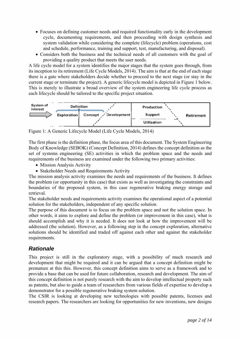
The starting point of engineering any system of interest is understanding the socio-economic and technological context in which the potential opportunity resides, in this instance regenerative braking for freight trains (Business of Mission Analysis, 2013). The stakeholder strategic goals, expectations and possibly requirements represent the business viewpoint. This concept is depicted in Figure 2 below. A concept definition covers two main activities:
Mission analysis Stakeholder needs and requirements
The mission analysis (a military originating term) or business analysis examines the needs of the business. It focuses on the primary purpose(s) of the solution. The stakeholder needs and requirements activity explores what capabilities stakeholders desire in accomplishing this mission or business case. These two concepts are expanded later in this document.
page 4 of 14
Figure 2: Business Strategy and Concept Definition (Business of Mission Analysis, 2013)
Definitions
Before proceeding to the mission analysis and stakeholder needs and requirements, a few definitions and concepts are discussed.
Regenerative concepts
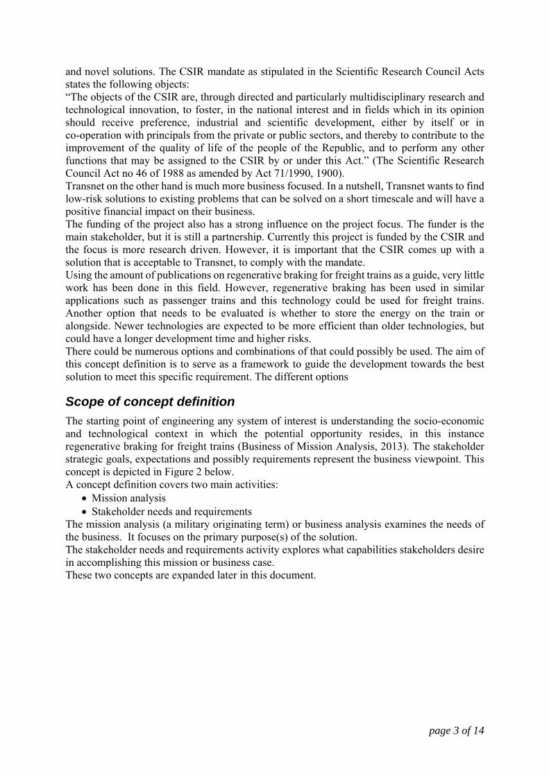
Wayside storage and onboard storage are the two options of regenerative braking with storage. With onboard storage, the energy generated from the regenerative braking s stored onboard the train. This does place a size limitation on the storage facility. The energy can also be transferred to a static external energy storage facility, the so-called wayside storage. The two regenerative storage option are illustrated in Figure 3 below.
Figure 3: Illustration of onboard and wayside storage (Motomi Shimada, 2010)
Catenary
The catenary refers to a system of overhead power lines that provide trains with electricity.
Energy flow and loss analysis
This section aims to give a brief overview of the methodology in defining the power chain for simulation software. A Sankey diagram can be useful to provide an overview of the energy usage of a train system, see Figure 4 below. Electrical energy coming into the train is combined with regenerated energy. This energy is used to move the train forward as well as keeping the auxiliary services energized. Along the entire energy usage chain there are losses.

page 5 of 14
Please note that the size of the arrow in the diagram is not always indicative of the amount of energy; the regenerated power can vary from zero to a system specific maximum. The sizes of the losses arrows (ohmic, electrical and mechanical) in relation to each other is indicative of a generic system. In this diagram, inputs are energy delivered by the grid (e.g. Eskom) and regenerated energy, defined as energy flowing from motors to the electrical side of the system during braking (REGENERATED). Outputs are energies consumed by trains, which comprises of traction and auxiliary energy. Energy losses that are wasted (converted to heat) are losses in conductors (ohmic) and rheostat losses. Since power must be balanced in the system, the relations may be defined as: ESUPPLY + EREGENERATED = ETRACTION + EAUXILIARY + EOHMIC + ERHEOSTAT (Alvaro J. Lopez, 2014) This basic equation does not yet take into account the energy storage system of an onboard system. This equation is merely given as a brief example of what inputs simulation software require. Due to the high cost of prototyping such large systems, simulation is an important design tool. Another shortcoming of this diagram is timing. It assumes that regenerated energy from regenerative braking is immediately used by another train. Therefore this diagram is for a system and not one train.
Figure 4: A typical electrified railway system Sankey diagram (Alvaro J. Lopez, 2014)
Mission analysis
Mission analysis is typically the largest part of the concept definition. As stated earlier, the mission analysis examines the problem statement and needs of the business. It focuses on identifying the primary purpose of the solution (mission). The opportunity here is regenerative braking and the purpose of the mission analysis is to:
Identify stakeholder Develop preliminary operational concepts
page 6 of 14
Define preliminary constraints for the solution space
Stakeholders
The main stakeholders identified on this project are Transnet and the CSIR. Transnet is the sponsor of this project that approached the CSIR with requirement and the CSIR will assist with the development of a system to meet the requirement. In addition, there are a few other indirect stakeholders. Transnet procures its electricity from Eskom. Transnet transports the ore and coal for suppliers who also have specific requirements. Regenerative braking saves electricity which in turn can lead to cost saving for Eskom’s clients. Regenerative braking could put constraints on load requirements and speeds which again could negatively affect Eskom’s clients. It is foreseen that this project will be a challenge from a technology point of view and will require a team of a number of experts in South Africa and beyond. This in turn will bring many more stakeholders on board.
Advantages to the stakeholders
Regenerative braking is about introducing a new technology to an existing system in order to be of economic, social or regulatory advantages to the owner. There are a number of aspects that need to be considered for the user’s expectations. As with any new system, there will be pros and cons. A regenerative braking system can have cost implications as well as additional risks. The potential overall advantage would be the sum total of pros minus cons. The most important criteria are listed below and should be used to determine whether this new technology has the potential to achieve the desired goals set out by the user. In addition, with new technologies come new risks. This should form part of the technology feasibility studies.
Pros
The use of regenerative braking and storage of energy has many potential cost and other savings advantages:
Reduction in overall electricity consumption
This is the most obvious, but not only advantage of regenerative braking. Regenerative braking reduces the peak power demand as well as the overall electricity consumption.
Reduction in carbon footprint
Reducing electricity consumption goes hand in hand with a reduced carbon footprint, but is an additional regulatory advantage that can lead to additional cost savings. Carbon tax is a new tax that is expected to be implemented on the 1st of January 2016. It will be phased in over a period to time to allow for smooth transition in adopting cleaner and more efficient processes and technologies. The proposed tax is R120 per tonne of CO2 equivalent with a 10% cost escalation over 5 years. There are thresholds applicable and this will reduce the effective rate to about R40 per tonne (The Proposed South African Carbon Tax, 2014). Transnet consumes large amounts of energy which will be subjected to carbon tax, be it direct carbon tax such as the use of fossil fuels or indirect carbon tax such as the use of electricity from Eskom. Both the direct and indirect carbon tax will in the long run affect the operating costs.
Reduction in operational costs
This covers any short-term and/or long-term cost saving benefit to the user, apart from the reduced electricity consumption already mentioned. It could be factors such as lower maintenance costs and long-life expectancy.
page 7 of 14
Potential addition of renewable energy sources (in case of alongside storage facility)
A regenerative system has a storage capability. This opens up the possibility to add renewable energy sources with additional electricity consumption and carbon footprint reduction. Depending on the user’s long-term policies, the possible addition of renewable energy sources could form part of the regenerative braking system requirements.
Cons
The cons listed below are not necessarily going to have a negative impact on this project. The aim is to list all the potential issues at this stage and manage them throughout the product life cycle.
Life expectancy and reliability
There are several factors that can impact on the life expectancy of the regenerative system. The environment can be a challenge as these trains travel through some of the hottest parts in South Africa. High temperatures generally lead to faster ageing and higher failure rates in electronic circuits and battery packs. The long lines in remote areas with limited infrastructure can also be an issue. A breakdown on these trains as a result of the regenerative braking system can become costly. The train cannot slow down just using brakes. The regenerative braking system will be an integral part of the safe operation of the train and a backup system might be required.
Maintenance
As this is a new system with potentially new test and maintenance requirements, the impact on the current maintenance system will have to be minimised as far as possible. Any additional costs in the maintenance and logistic support will have to be factored into the cost benefit analysis.
Training and safety
Ideally the system has to function automatically without intervention required by the train drivers. In practise however, additional safety systems and procedures will have to be installed. For example electronic circuits and battery packs can increase the risk of fire.
Preliminary constraints
Constraints on regenerative braking
Not all energy generated during braking can be stored. Each component in the regenerative chain can have a limiting effect on the regenerative braking and retrieval system, be it efficiency, peak power transfer or capacity. These need to be defined in order to determine an estimate of how much energy can realistically be saved by a regenerative braking system for a specific system. Energy Efficient Technologies for Railways (Regenerative braking in 50 Hz, 25 kV systems, 2002) estimates that only about 20% the energy can be recovered on freight trains. This was for one specific topology that feeds the energy back into the grid; there are other topologies that can be employed to increase this percentage. The topology has significant influence on the conversion efficiency. On-board storage is efficient, wayside storage had additional losses and feeding back into the grid is more complex with even more challenges in maximising the conversion efficiency. Each component in the regenerative braking system limits or reduces the conversion efficiency.
page 8 of 14
Share of recoverable energy
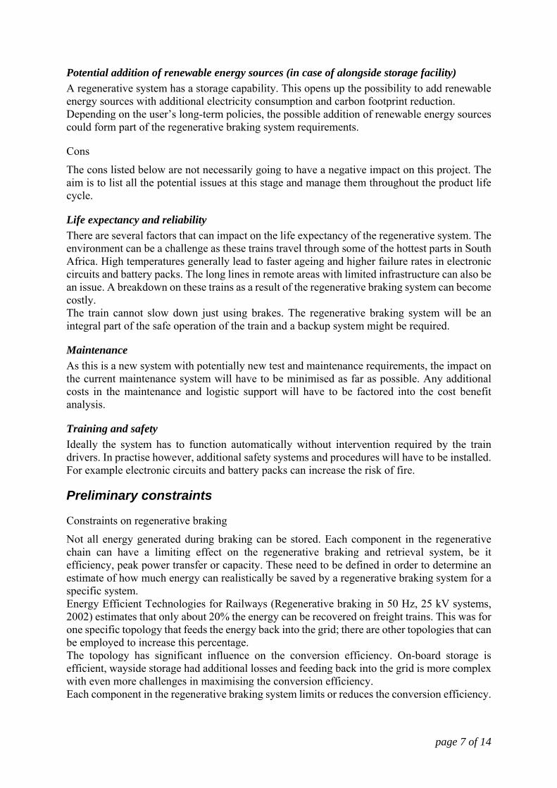
A number of factors limit the share of the recoverable energy. It is best to analyze this for each system. The regenerative energy storage system comprises of at least the building blocks depicted in Figure 5 below. During the braking cycle, energy generated by the traction motor is transferred through a converter to a storage unit. To retrieve the energy, stored energy must again travel through a converter to the motor. Each item in the chain has limitations such as peak energy transfer, efficiencies and capacity. These are discussed below to provide an overview of the constraints of regenerative braking system components.
Figure 5: Regenerative energy transfer: a) storage and b) retrieval
Peak energy transfer
Peak energy refers to the peak power transfer. The share of recoverable energy during braking depends heavily on speed and stopping pattern. In the traction motor braking power by regenerative braking can be around 30% greater than that of powering, which is far inferior to dynamic braking where power typically exceeds 2·5 times that of powering. In other words, for optimum regenerative braking, the train has to stop slower, an added time penalty. This 30% additional power generation capability is achieved by exploiting the over-voltage capability of the traction motors without increasing the current. The converter should not have a limiting factor on the peak energy transfer. Energy storage units have a peak conversion rate limit as well. For super capacitors it is very fast, but for battery packs, the conversion rate as relatively slow. Any energy that is generated at a higher peak than the regenerative braking system can absorb is channeled to rheostat braking and cannot be retrieved.
Efficiencies
Each sub-component has known efficiencies which generally are a given. The conversion efficiency of batteries can vary significantly between various chemistries, as well as state of charge of the battery.
Traction Motor (generator)
Bi-directional Converter
Energy Storage Unit
Traction Motor (forward motion)
Energy Storage Unit
Bi-directional Converter
b
a
page 9 of 14
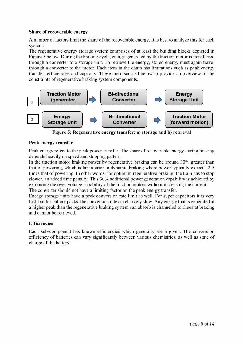
The losses in each system add up and reduce the overall efficiency. There is little (if any) quantitative data on these effects (International Union of Railways, 2002). Table 1 below gives some estimates for 25kV 50Hz systems.
Table 1: Typical Efficiencies ((International Union of Railways, 2002)
Total potential
Correction due to traction efficiency
Correction due to catenary receptivity
Correction due to blended braking
Corrected potential
Main lines 15% 0,85 0,4 0,8 4%
Regional lines 35% 0,85 0,5 0,8 12%
Local lines 45% 0,85 0,6 0,8 18%
Freight lines 20% 0,85 0,4 0,5 3%
Capacity
A regenerative braking system has a limit on the amount of energy that it can store, it is called storage capacity. An onboard storage system is typically constrained by size limitations whereas a wayside storage system does not have this limitation. The storage capacity generally does get more complex as it increases in size.
Lifespan and failure rate
Each technology has a limited lifespan as well as a failure rate. Once again batteries are the weak link with a limited cycle life as well as a risk of premature failures due to quality control issues during manufacture.
Environmental
This regenerative system has to operate in an environment that is exposed to extreme temperatures, all weather conditions and dust. This can severely affect the reliability of a system, or increase the cost of a system to enable it to operate reliably in these conditions. Wayside storage facilities have the added advantage that they can be housed in temperature and controlled buildings in a relatively clean environment.
Technologies being used and researched
Energy regenerated during braking can either be fed back into the grid or stored for later use. The preliminary investigation will have to come up with recommendations for this project. This could be a single technology or a combination of technologies. Feeding the energy back into the grid to be used by other users nullifies the need for energy storage. As this is a short burst of energy that is fed back into the grid, it is not favoured by bulk electricity suppliers. Several energy storage technologies are available to be selected for the application of hybrid locomotives, such as
Battery packs e.g. Li-ion, LiFePO4, lead-acid, NiMH etc. Super capacitors, Flywheels,
((Sun, Cole, Spiryagin, Rasul, Godber, & Hames, Energy storage system analysis for heavy haul hybrid locomotives, 2012), (Sun, Cole, Spiryagin, Rasul, Godber, & Hames, Energy usage analysis for australian heavy haul trains on typical track routes, 2012), (Jaafar, Akli, Roboam, & Jeunesse, 2009), (Pede, 2007), (Barrade, Destraz, & Rufer, 2004)
page 10 of 14
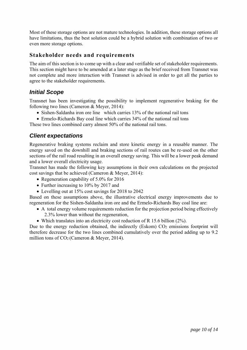
Most of these storage options are not mature technologies. In addition, these storage options all have limitations, thus the best solution could be a hybrid solution with combination of two or even more storage options.
Stakeholder needs and requirements
The aim of this section is to come up with a clear and verifiable set of stakeholder requirements. This section might have to be amended at a later stage as the brief received from Transnet was not complete and more interaction with Transnet is advised in order to get all the parties to agree to the stakeholder requirements.
Initial Scope
Transnet has been investigating the possibility to implement regenerative braking for the following two lines (Cameron & Meyer, 2014):
Sishen-Saldanha iron ore line which carries 13% of the national rail tons Ermelo-Richards Bay coal line which carries 34% of the national rail tons
These two lines combined carry almost 50% of the national rail tons.
Client expectations
Regenerative braking systems reclaim and store kinetic energy in a reusable manner. The energy saved on the downhill and braking sections of rail routes can be re-used on the other sections of the rail road resulting in an overall energy saving. This will be a lower peak demand and a lower overall electricity usage. Transnet has made the following key assumptions in their own calculations on the projected cost savings that be achieved (Cameron & Meyer, 2014):
Regeneration capability of 5.0% for 2016 Further increasing to 10% by 2017 and Levelling out at 15% cost savings for 2018 to 2042
Based on these assumptions above, the illustrative electrical energy improvements due to regeneration for the Sishen-Saldanha iron ore and the Ermelo-Richards Bay coal line are:
A total energy volume requirements reduction for the projection period being effectively 2.3% lower than without the regeneration,
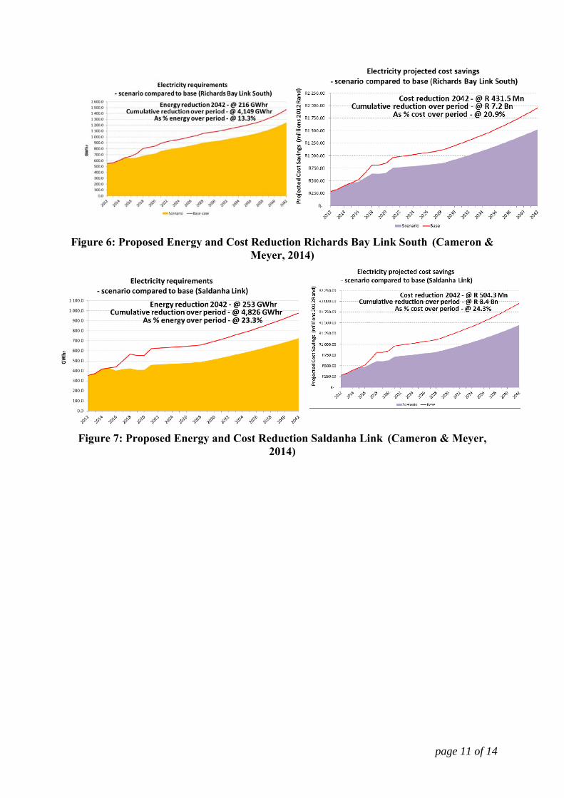
Which translates into an electricity cost reduction of R 15.6 billion (2%). Due to the energy reduction obtained, the indirectly (Eskom) CO2 emissions footprint will therefore decrease for the two lines combined cumulatively over the period adding up to 9.2 million tons of CO2 (Cameron & Meyer, 2014).
page 11 of 14
Figure 6: Proposed Energy and Cost Reduction Richards Bay Link South (Cameron & Meyer, 2014)
Figure 7: Proposed Energy and Cost Reduction Saldanha Link (Cameron & Meyer, 2014)
page 12 of 14
Conclusions and Recommendations
As stated in the introduction, this concept definition might seem premature as the project is still in the exploration phase. However, with the many stakeholders come many expectations and this needs to be managed with clear communication to the stakeholders. As this project has a very specific focus, the development in the solution space must continually focus on addressing the requirement, even in the exploratory phase. A number of technologies for regenerative braking have been tested around the world and a few pilot studies have been completed successfully. However, the requirements of Transnet should be regarded as very different for the following reasons:
Size of freight trains (especially the Sishen-Saldanha line): The freight trains are up to a few kilometers long and the energy generated during braking is sizeable.
Operating environment: The trains operate over long distances, remote locations and are subjected to extreme weather conditions.
A preliminary literature survey indicates that this technology is far from mature. This increases the technical risk of this project. This risk has to be mitigated and controlled. The following recommendations are proposed for the next phase, the preliminary investigation:
Requirements definition
This project is primarily aimed at meeting a specific client requirement. The clients’ expectations need to be defined in detail and revisited regularly during the preliminary investigation phase. It might not be technically possible to meet all the clients’ requirements, but the client might be satisfied with proposed changes.
Technology investigation
This technology investigation should also include discussions with various experts around the world on the maturity and feasibility of the various building blocks, especially the energy storage options.
Simulation
Simulation can be a very useful tool during all phases of product development, from concept exploration to detail development. However, as it is a simplification of reality, it is a challenge to build the model accurate enough for it to add value to the project. Simulation tools need to be validated and calibrated with small scale pilot tests. OpenPowerNet, a traction power supply and engine simulation software developed by Institut für Bahntechnik GmbH is an example of a simulation tool.
page 13 of 14
References
Alvaro J. Lopez, R. R.-C. (2014). Assessment of energy-saving techniques in direct current-electrified mass transit systems. Transportation Research Part C 38, 85-100.
Barrade, P., Destraz, B., & Rufer, A. (2004, October 6-8). Hybrid vehicle in railways applications: supercapacitive energy storage for diesel-electric locomotives. Paris, France: IEEE.
Business of Mission Analysis. (2013, 10 31). Retrieved 03 30, 2015, from Guide to the Systems Engineering Body of Knowledge: http://sebokwiki.org/wiki/Business_or_Mission_Analysis
Cameron, M., & Meyer, F. (2014). The importance of long-term strategic ernergy requirements planning: A Transnet case study. African Utility Week. Cape Town.
Concept Definition. (2014, 12 5). Retrieved 03 24, 2015, from Guide to the System Engineering Body of Knowledge: http://sebokwiki.org/wiki/Concept_Definition
Halligan, R. J. (2011, October 6). Operational Concept Description. Operational Concept Description. Melbourne: Project Performance International.
Jaafar, A., Akli, C. S., Roboam, X., & Jeunesse, A. (2009). Sizing and energy management of a hybrid locomotive based on flywheel and accumulators. IEEE Transactions on Vehicular Technology, vol. 58, no. 8, pp. 3947 - 3958.
Life Cycle Models. (2014, 12 5). Retrieved 03 24, 2015, from Guide to the Systems Engineering Body of Knowledge: http://sebokwiki.org/wiki/Life_Cycle_Models
Motomi Shimada, R. O. (2010, 01 04). Energy Storage System for Effective Use of Regenerative Energy in Electrified Railways. Retrieved 03 30, 2015, from Hitachi: http://www.hitachi.com/rev/pdf/2010/r2010_01_104.pdf
Pede, G. (2007). Thermo-economic analysis of dual-mode hybrid trains. International Conference of Clean Electrical Power - Renewable Energy Resources Impact. Capri, Italy.
Regenerative braking in 50 Hz, 25 kV systems. (2002, 12 02). Retrieved 03 26, 2015, from Energy Efficiency Technologies for Railways: http://www.railway-energy.org/static/Regenerative_braking_in_50_Hz__25_kV_systems_104.php
Sun, Y., Cole, C., Spiryagin, M., Rasul, M., Godber, T., & Hames, S. (2012). Energy storage system analysis for heavy haul hybrid locomotives. Proceedings of the Conference on Railway Engineering (CORE 2012), (pp. pp. 581-589). Brisbane.
Sun, Y., Cole, C., Spiryagin, M., Rasul, M., Godber, T., & Hames, S. (2012). Energy usage analysis for australian heavy haul trains on typical track routes. Proceedings of the Conference on Railway Engineering (CORE 2012), (pp. pp. 559-567). Brisbane.
The Proposed South African Carbon Tax. (2014). Retrieved 3 18, 2015, from The Carbon Report: http://www.thecarbonreport.co.za/the-proposed-south-african-carbon-tax/
The Scientific Research Council Act no 46 of 1988 as amended by Act 71/1990. (1900). The Scientific Research Council Act no 46 of 1988 as amended by Act 71/1990. Pretoria, South Africa.

page 14 of 14
Biography
Achmed Giesler is an Electronic Engineer (Stellenbosch, 1985) who also holds an MBA (Stellenbosch, 2005), specialising in product development. He has many years of product development experience in the defence industry and biomedical engineering fields and won two SABS design institute awards for medical products. He was also part of a European consortium that developed the highly successful JENNY methanol fuel cell for military applications. Currently he is focusing on power management, battery pack development and energy systems for man-portable applications. He was a speaker at the Soldier Technology 2013 conference in London.