transient response improvement of dc-dc buck …...transient response improvement of dc-dc buck...
TRANSCRIPT

Transient Response Improvement of DC-DC Buck Converter by Adjustable Triangular Wave Generator
Shu Wu, Yasunori Kobori, Haruo Kobayashi
Gunma University, Japan
2014/7/10 1
電子情報通信学会 電子通信エネルギー技術研究会 広島工業大学 (2014年7月10日(木)-7月11日(金))

Outline
• Research Objective • Proposed Triangular Wave Generator
• Duty Cycle Modulation • Slope Adjustable Triangular Wave Generator • Improvement of Transient Response
• Stability Analysis
• Simulation Results • Line Transient Response • Load Transient Response
• Conclusion
2014/7/10 2

Outline
• Research Objective • Proposed Triangular Wave Generator
• Duty Cycle Modulation • Slope Adjustable Triangular Wave Generator • Improvement of Transient Response
• Stability Analysis
• Simulation Results • Line Transient Response • Load Transient Response
• Conclusion
2014/7/10 3
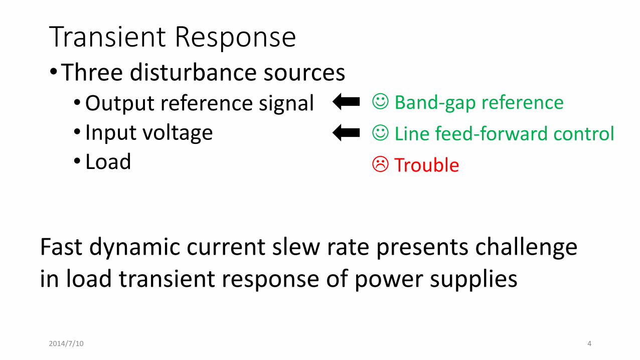
Transient Response •Three disturbance sources •Output reference signal • Input voltage • Load
Band-gap reference
Line feed-forward control
Trouble
Fast dynamic current slew rate presents challenge in load transient response of power supplies
2014/7/10 4

Previous Control Schemes •Feedback • Voltage-Mode Control (VMC)
• Easy to design and analyze • Limited bandwidth: slow response
• Current-Mode Control (CMC) • Inherent line feed-forward control • Wide band • Slope compensation • Current sensor
•Feed-forward Complicated non-linear calculation 2014/7/10 5

Research Objective • Design a slope adjustable triangular wave generator to
improve transient response of DC-DC buck converter • Based on VMC: compared to CMC
---Not require current sensor and slope compensation
• The slope is regulated by input and output voltage: compared to conventional VMC
---Provide line feed-forward control and higher band-width
• Simple: compared to previous feed-forward control
---Not require complicated calculation
2014/7/10 6

Outline
• Research Objective • Proposed Triangular Wave Generator
• Duty Cycle Modulation • Slope Adjustable Triangular Wave Generator • Improvement of Transient Response
• Stability Analysis
• Simulation Results • Line Transient Response • Load Transient Response
• Conclusion
2014/7/10 7
t Reference
+
- +
-
Error Amplifier Comparator
Output 𝑉𝐸
Triangular wave
PWM
V PWM
Triangular Wave 𝑉𝐸
𝑰𝑳𝑹𝒊
+
- +
-
Error Amplifier Comparator
Output 𝑉𝐸
PWM
Reference
PWM 𝑉𝐸 𝑰𝑳𝑹𝒊
t
V
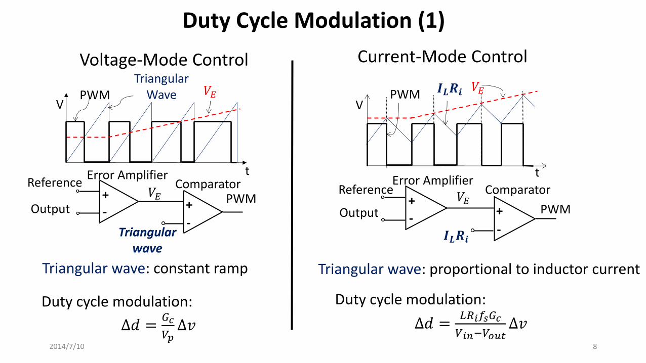
Voltage-Mode Control Current-Mode Control
Triangular wave: constant ramp Triangular wave: proportional to inductor current
Duty cycle modulation:
∆𝑑 =𝐺𝑐
𝑉𝑝∆𝑣
Duty cycle modulation:
∆𝑑 =𝐿𝑅𝑖𝑓𝑠𝐺𝑐
𝑉𝑖𝑛−𝑉𝑜𝑢𝑡∆𝑣
Duty Cycle Modulation (1)
2014/7/10 8

•During load transient response, slope of triangular wave always keep constant (conventional VMC and CMC).
•Duty cycle modulation by slope (proposed).
Duty Cycle Modulation (2)
∆𝑑 =𝑡𝑜𝑛2−𝑡𝑜𝑛1
𝑇𝑠
=𝑉𝐸
𝑇𝑠
1
𝑀2−
1
𝑀1
=𝑉𝐸
𝑇𝑠∆
1
𝑀
Duty cycle variation is inversely proportional to slope.
2014/7/10 9
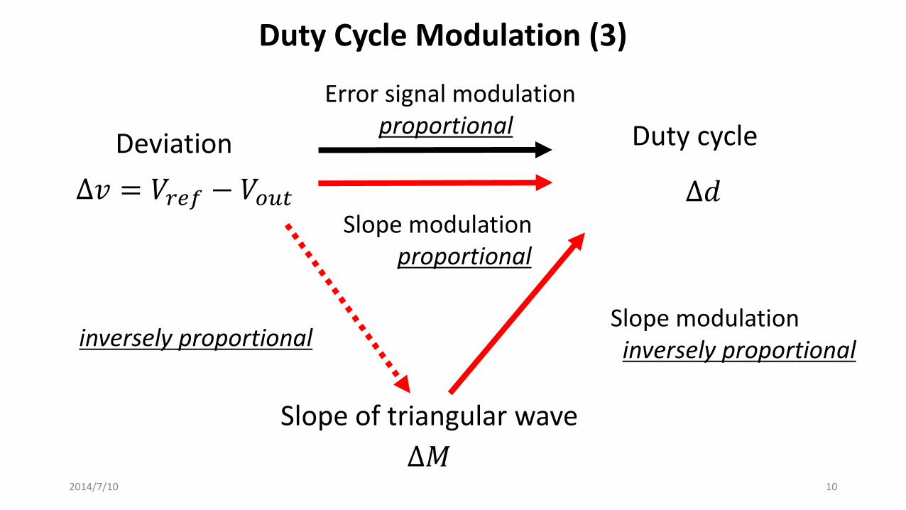
Duty Cycle Modulation (3)
Deviation Duty cycle
∆𝑣 = 𝑉𝑟𝑒𝑓 − 𝑉𝑜𝑢𝑡 ∆𝑑
Slope of triangular wave
∆𝑀
Error signal modulation proportional
Slope modulation inversely proportional inversely proportional
Slope modulation proportional
2014/7/10 10
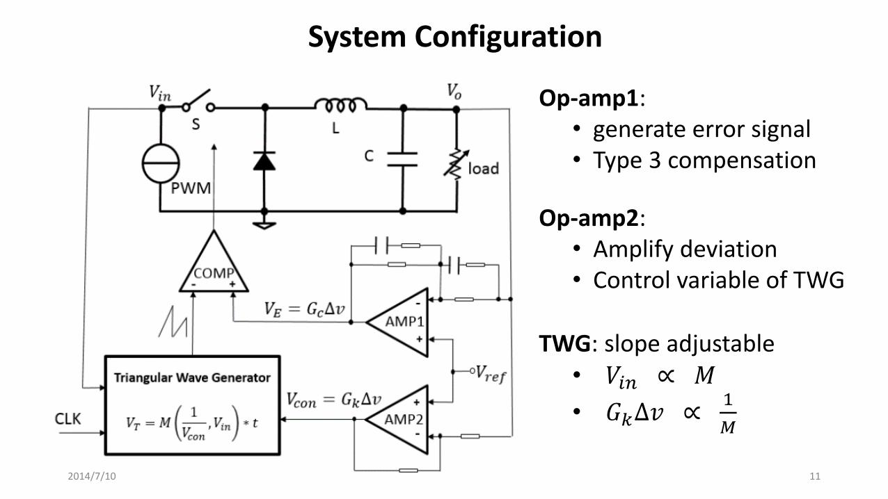
System Configuration
Op-amp1: • generate error signal • Type 3 compensation
Op-amp2: • Amplify deviation • Control variable of TWG
TWG: slope adjustable • 𝑉𝑖𝑛 ∝ 𝑀
• 𝐺𝑘∆𝑣 ∝ 1
𝑀
2014/7/10 11
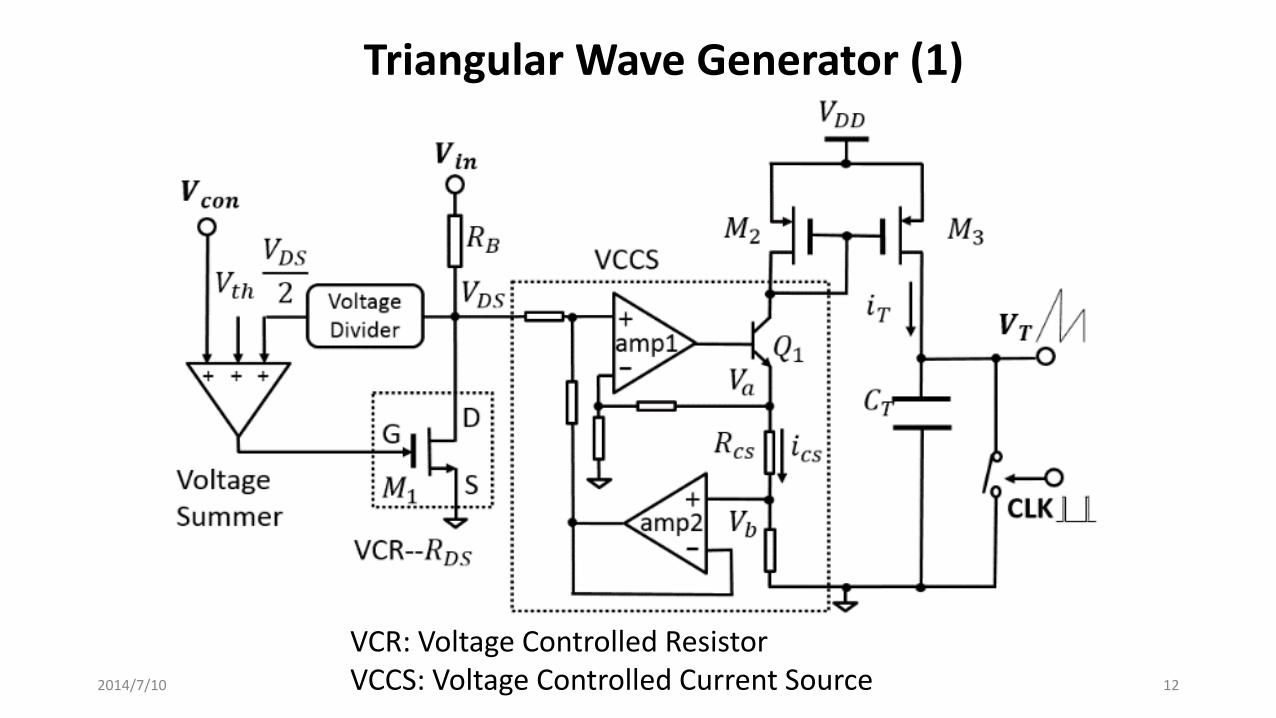
Triangular Wave Generator (1)
VCR: Voltage Controlled Resistor VCCS: Voltage Controlled Current Source 2014/7/10 12

•VCR
Triangular Wave Generator (2)
S
G D
𝑽𝒄𝒐𝒏
𝑉𝐷𝑆2
𝑉𝑡ℎ
+ + +
Voltage Summer
𝑀1
VCR--𝑅𝐷𝑆
𝑽𝒊𝒏
𝑉𝐷𝑆 Voltage Divider
Triode region
𝐼𝐷 = 𝐾𝑛 𝑉𝐺𝑆 − 𝑉𝑡ℎ 𝑉𝐷𝑆 −𝑉𝐷𝑆
2
2 where 𝐾𝑛 = 𝜇𝑛𝐶𝑜𝑥𝑊 𝐿
1
𝑅𝐷𝑆=
𝐼𝐷
𝑉𝐷𝑆= 𝐾𝑛 𝑉𝐺𝑆 − 𝑉𝑡ℎ −
𝑉𝐷𝑆
2
Set 𝑉𝐺𝑆 = 𝑉𝑡ℎ +𝑉𝐷𝑆
2+ 𝑉𝑐𝑜𝑛 by voltage summer,
get a voltage controlled resistor
𝑅𝐷𝑆 =1
𝐾𝑛𝑉𝑐𝑜𝑛 ……(1)
𝑅𝐵
If 𝑅𝐵 ≫ 𝑅𝐷𝑆
𝑽𝑫𝑺 =𝟏
𝑲𝒏𝑹𝑩
𝑽𝒊𝒏
𝑽𝒄𝒐𝒏 ……(2)
𝑽𝑫𝑺 is controlled by input voltage and control variable 2014/7/10 13
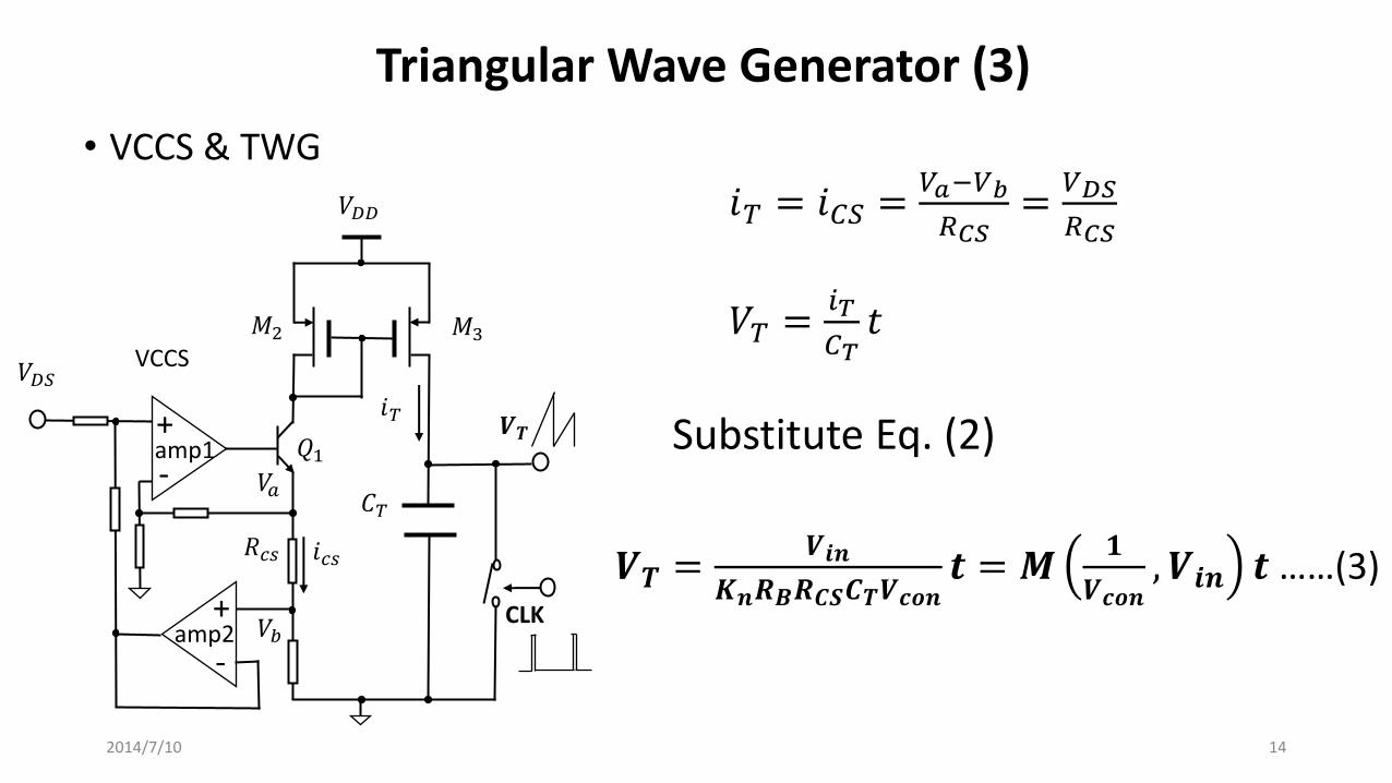
• VCCS & TWG
Triangular Wave Generator (3)
𝑉𝐷𝐷
+ amp1
𝑀2 𝑀3
𝑽𝑻
CLK
VCCS
𝐶𝑇
𝑅𝑐𝑠
𝑉𝑎
𝑉𝑏
𝑖𝑇
𝑖𝑐𝑠
𝑄1
𝑉𝐷𝑆
𝑖𝑇 = 𝑖𝐶𝑆 =𝑉𝑎−𝑉𝑏
𝑅𝐶𝑆=
𝑉𝐷𝑆
𝑅𝐶𝑆
-
amp2 -
+
𝑉𝑇 =𝑖𝑇
𝐶𝑇𝑡
Substitute Eq. (2)
𝑽𝑻 =𝑽𝒊𝒏
𝑲𝒏𝑹𝑩𝑹𝑪𝑺𝑪𝑻𝑽𝒄𝒐𝒏𝒕 = 𝑴
𝟏
𝑽𝒄𝒐𝒏, 𝑽𝒊𝒏 𝒕 ……(3)
2014/7/10 14
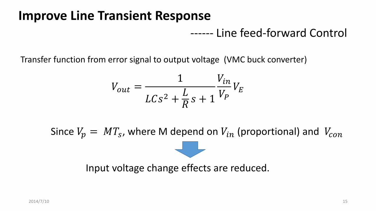
𝑉𝑜𝑢𝑡 =1
𝐿𝐶𝑠2 +𝐿𝑅𝑠 + 1
𝑉𝑖𝑛𝑉𝑃
𝑉𝐸
Improve Line Transient Response ------ Line feed-forward Control
Transfer function from error signal to output voltage (VMC buck converter)
Since 𝑉𝑝 = 𝑀𝑇𝑠, where M depend on 𝑉𝑖𝑛 (proportional) and 𝑉𝑐𝑜𝑛
Input voltage change effects are reduced.
2014/7/10 15
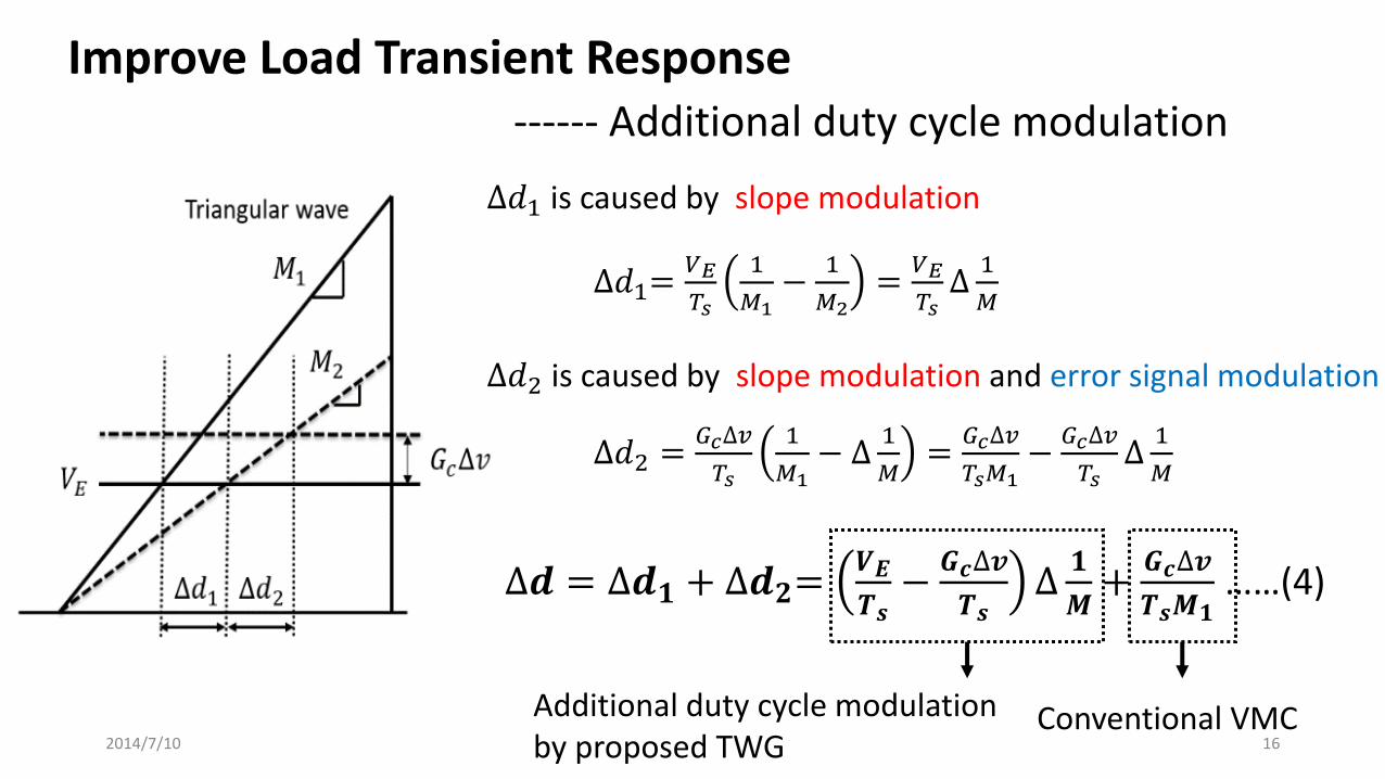
Improve Load Transient Response ------ Additional duty cycle modulation
∆𝑑1 is caused by slope modulation
∆𝑑1=𝑉𝐸
𝑇𝑠
1
𝑀1−
1
𝑀2=
𝑉𝐸
𝑇𝑠∆
1
𝑀
∆𝑑2 =𝐺𝑐∆𝑣
𝑇𝑠
1
𝑀1− ∆
1
𝑀=
𝐺𝑐∆𝑣
𝑇𝑠𝑀1−
𝐺𝑐∆𝑣
𝑇𝑠∆
1
𝑀
∆𝑑2 is caused by slope modulation and error signal modulation
∆𝒅 = ∆𝒅𝟏 + ∆𝒅𝟐=𝑽𝑬
𝑻𝒔−
𝑮𝒄∆𝒗
𝑻𝒔∆
𝟏
𝑴+
𝑮𝒄∆𝒗
𝑻𝒔𝑴𝟏 ……(4)
Conventional VMC Additional duty cycle modulation by proposed TWG 2014/7/10 16
Outline
• Research Objective • Proposed Triangular Wave Generator
• Duty Cycle Modulation • Slope Adjustable Triangular Wave Generator • Improvement of Transient Response
• Stability Analysis
• Simulation Results • Line Transient Response • Load Transient Response
• Conclusion
2014/7/10 17

System Block Diagram
∆𝒅 = ∆𝒅𝟏 + ∆𝒅𝟐≈ 𝑨∆𝒗 +𝑮𝒄
𝑽𝒑_𝒔𝒕𝒂𝒕𝒊𝒄∆𝒗
Ignore non-linear terms
𝐴 =𝐾𝑛𝑅𝐵𝑅𝐶𝑆𝐶𝑇𝑉𝐸𝐺𝑘
𝑇𝑠𝑉𝑖𝑛
𝑉𝑝_𝑠𝑡𝑎𝑡𝑖𝑐 = 𝑇𝑠𝑀1
Open-loop transfer function: T = 𝐴 +𝐺𝑐
𝑉𝑝_𝑠𝑡𝑎𝑡𝑖𝑐𝐺𝑣𝑑𝐻
2014/7/10 18

Example
Power Stage • 𝑉𝑖𝑛 = 5𝑉 • 𝑉𝑜𝑢𝑡 = 3.5𝑉 • 𝑉𝑝_𝑠𝑡𝑎𝑡𝑖𝑐 = 3𝑉
• 𝐿 = 10𝜇𝐻 (𝐸𝑆𝑅 = 10𝑚𝛺) • 𝐶 = 50𝜇𝐹(𝐸𝑆𝑅 = 10𝑚𝛺) • 𝑅 = 35𝛺 • 𝑓𝑠𝑤𝑖𝑡𝑐ℎ = 1𝑀𝐻
Phase Compensation • Type 3 compensation
• 𝑓𝑐 =𝑓𝑠𝑤𝑖𝑡𝑐ℎ
20= 50𝑘𝐻𝑧
• PM = 40° Design for conventional VMC
TWG • 𝐺𝑘 = 10 • 𝑅𝐵 = 1𝑘𝛺 • 𝐾𝑛 ≈ 3 • 𝑅𝑐𝑠 = 100𝛺 • 𝐶𝑇 = 50𝑝𝐹
𝑨 ≈ 𝟑𝟎
2014/7/10 19
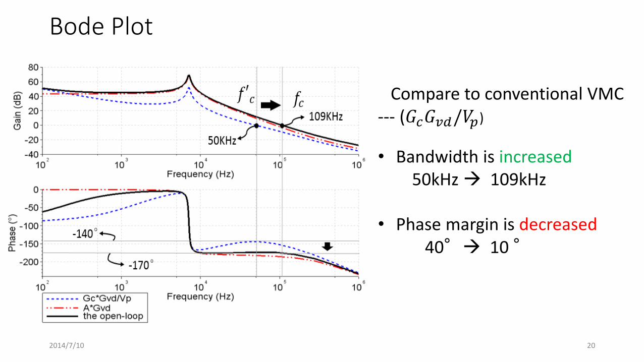
Bode Plot
Compare to conventional VMC --- (𝐺𝑐𝐺𝑣𝑑/𝑉𝑝)
• Bandwidth is increased 50kHz 109kHz • Phase margin is decreased 40° 10 °
2014/7/10 20

Nyquist Plot
2014/7/10 21

Increase Phase Margin
Add a high frequency zero point to A: A A∗ 𝑠 + 𝜔ℎ
• Bandwidth 109kHz 130kHz • Phase Margin 10° 30 °
2014/7/10 22

Outline
• Research Objective • Proposed Triangular Wave Generator
• Duty Cycle Modulation • Slope Adjustable Triangular Wave Generator • Improvement of Transient Response
• Stability Analysis
• Simulation Results • Line Transient Response • Load Transient Response
• Conclusion
2014/7/10 23

Line Transient Response (1)
𝑉𝑖𝑛
𝑉𝑜𝑢𝑡
Without proposed TWG
With proposed TWG
𝑉𝑖𝑛: 5V ↔ 8V
( Simulation conditions is shown in P19) 2014/7/10 24

Line Transient Response (2) 𝑉 𝑜
𝑢𝑡
𝑉 𝐸 &
TW
P
WM
55mV 5mV
Without proposed TWG With proposed TWG 2014/7/10 25
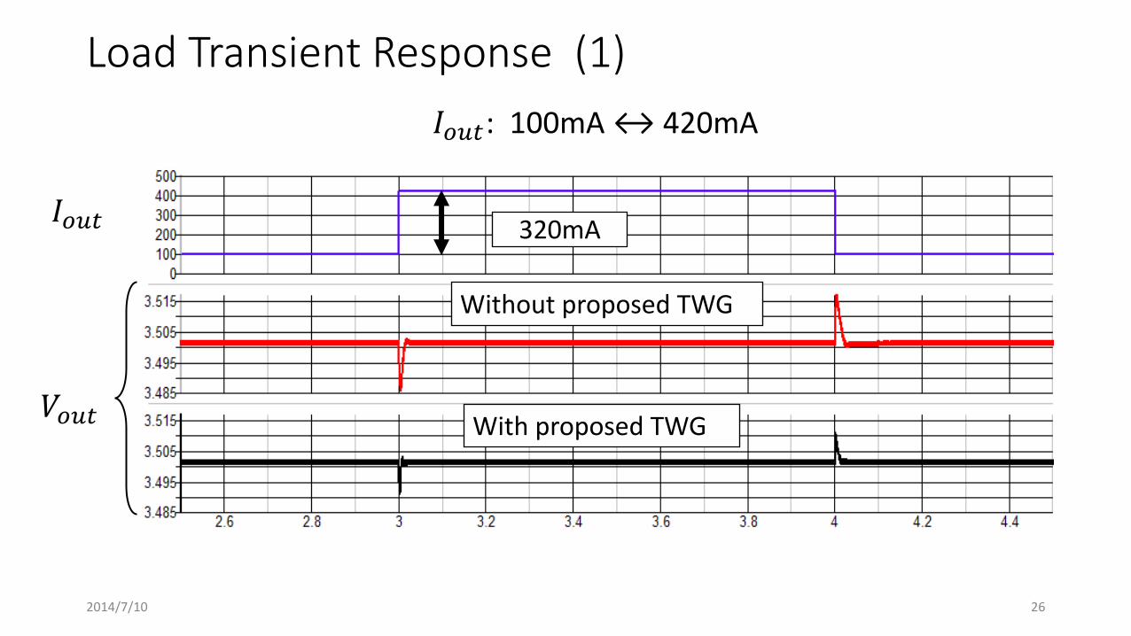
Load Transient Response (1)
𝐼𝑜𝑢𝑡
𝑉𝑜𝑢𝑡
Without proposed TWG
With proposed TWG
320mA
𝐼𝑜𝑢𝑡: 100mA ↔ 420mA
2014/7/10 26
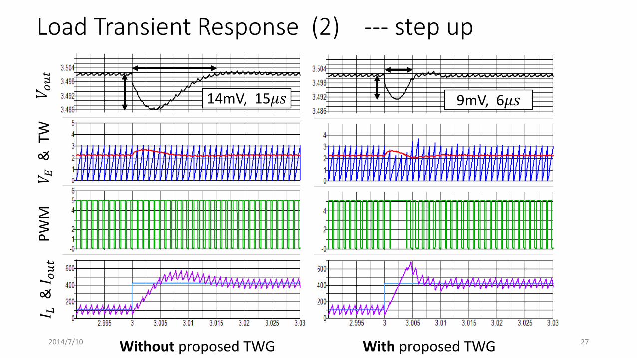
Load Transient Response (2) --- step up 𝑉 𝑜
𝑢𝑡
𝑉 𝐸 &
TW
P
WM
𝐼 𝐿 &
𝐼𝑜𝑢𝑡
14mV, 15𝜇𝑠 9mV, 6𝜇𝑠
Without proposed TWG With proposed TWG 2014/7/10 27
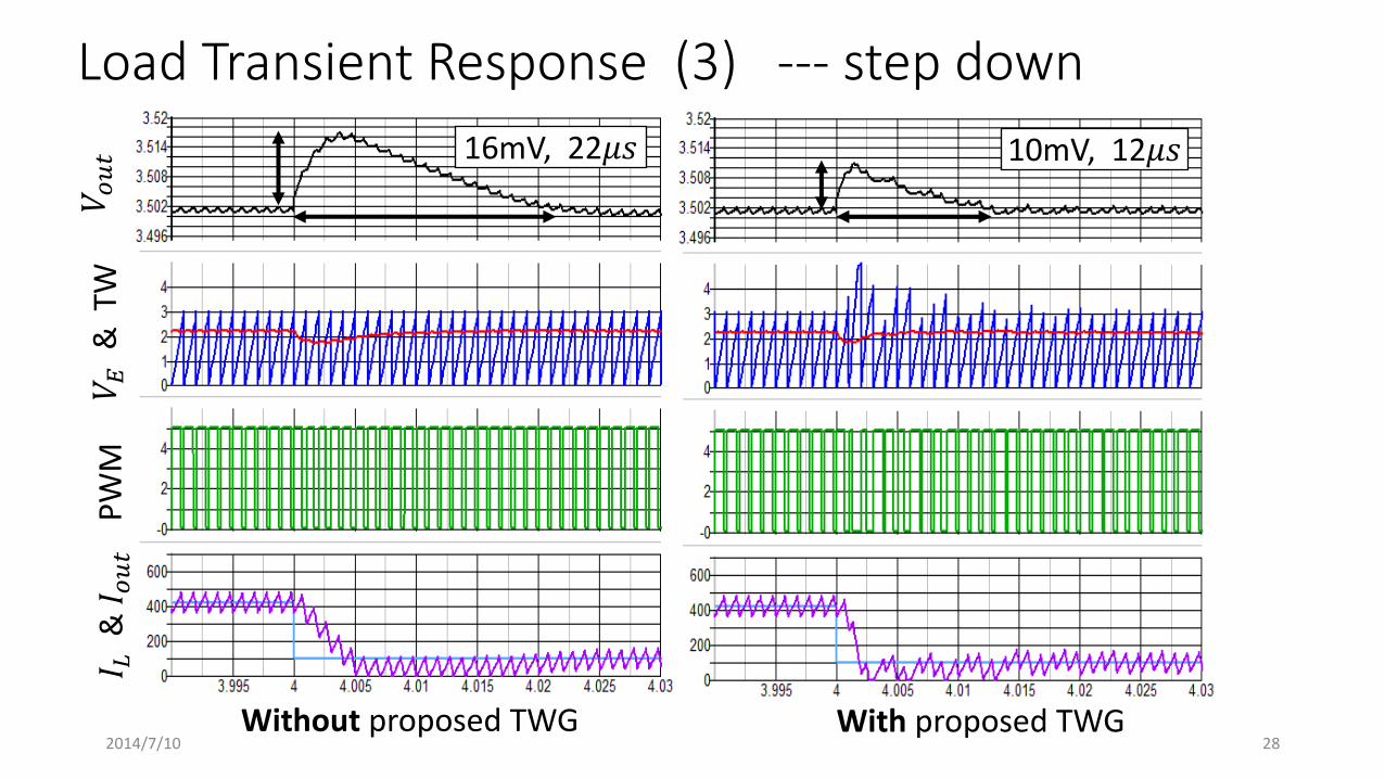
Load Transient Response (3) --- step down 𝑉 𝑜
𝑢𝑡
𝑉 𝐸 &
TW
P
WM
𝐼 𝐿 &
𝐼𝑜𝑢𝑡
16mV, 22𝜇𝑠 10mV, 12𝜇𝑠
Without proposed TWG With proposed TWG 2014/7/10 28
Outline
• Research Objective • Proposed Triangular Wave Generator
• Duty Cycle Modulation • Slope Adjustable Triangular Wave Generator • Improvement of Transient Response
• Stability Analysis
• Simulation Results • Line Transient Response • Load Transient Response
• Conclusion
2014/7/10 29
Conclusion
•Design a slope adjustable triangular wave generator for DC-DC converter. • Improve line and load transient response • Simple - Not require current sensor and slope compensation
•Next Step circuit implementation
2014/7/10 30

The End
Thanks for your attention
2014/7/10 31

Q&A
• Normally, we increased the feedback gain to improve transient response. So that, what is the advantage of your method, comparing to the normal method?
A: with a larger feedback gain, we can get higher bandwidth, but it is limited by the gain-bandwidth product of op-amp, especially, VMC need Type 3 compensation. The proposed method increase the open-loop bandwidth by a novel way. Although it also limited by op-amp, but not so much as conventional method.
• During line transient response, which parameter is changed?
A: Since the triangular wave slope is controlled by input voltage, it means the peak value of triangular wave --Vp also be controlled by input. During line transient response, the variation in Vin is eliminated by the changed Vp. 2014/7/10 32