transformer winding design rev 04 11-13-09libvolume8.xyz/textile/btech/semester6/textile... ·...
TRANSCRIPT

Transformer Winding Design
The Design and Performance of Circular Disc, Helical and Layer Windings for Power Transformer Applications
Minnesota Power Systems Conference
November 3‐5, 2009
Earl Brown Heritage Center
University of Minnesota
Author and Presenter:
David L. Harris, P.E. Customer Technical Executive Waukesha Electric Systems
Transformer Winding Design The Design and Performance of Circular Disc, Helical and Layer Windings for Power Transformer Applications
Page 2 of 12
Winding design and manufacturing practices for power and distribution transformers has focused in the differences between rectangular core and coils and layer windings common in the production of distribution transformers and disc and helical windings and circular core designs common in power transformers. In the small power transformer market defined as 5-15 MVA, ONAN, with primary winding voltages up through 69 kV class, both core and coil designs are commercially available.
Rectangular core and coils and layer windings offer the advantage of lower costs for manufacturing compared to power class circular core and coils with disc and helical windings. Distribution transformers are applied at lower voltages, ratings stated in KVA, lower short circuit and thermal duties serving residential and commercial loads. Power transformers are applied at voltages from 15 kV to 765 kV and higher, ratings stated in MVA, short circuit duties are high, thermal loading variable and in some cases severe. Generator Step-up transformers, unit auxiliary transformers, multiple winding transformers, autotransformers, transmission and distribution bulk power substation service with and without load tap changing all must be designed to withstand the rigorous duty for these power class transformer applications.
Thermal design and operation considerations
Heating of the windings results from the load losses of the winding and are a sum of the conductor resistance losses and stray and eddy losses. Resistance losses (I2R) are a function of load current and the resistance of the winding conductor. Stray and eddy losses include the circulating current losses between parallel connected conductors as well as the eddy current losses caused by the leakage flux entering the conductor, which depend on the dimension of the conductor and direction of the flux impinging upon it.
A second function for the transformer oil is to act as a cooling system to transfer the heat produced in the transformer windings to the cooling system through the processes of conduction, convection and radiation. For optimum winding cooling, it is desireable that the moving oil contact with every winding conductor for maximum convection and conduction of the conductor heat from the winding to the mineral oil.
Satisfactory drying of the insulation prior to oil impregnation in the factory is one significant step to produce a transformer with minimum moisture content when shipped for longer insulation life. Transformer life is based on aging of the cellulose insulation and the most significant factor in the equation is hot spot temperature. One significant cause of catastrophic transformer failure is bubble evolution in the oil resulting from moisture release from the cellulose insulation during higher hot spot temperatures. IEEE Std C57.91-1995 IEEE Guide for Loading Mineral-Oil-Immersed Transformers provides a discussion of the aging process of the transformer cellulose insulation. Winding design not only affects cooling during normal & emergency loading operation, but is a factor in the drying process in the factory. Rectangular core and coil designs are frequently used for distribution transformer designs and offer advantages of reduction in direct labor and material when compared to circular core and coils with disc and helical windings usually wound with sheet conductors for the LV winding. The rectangular core design reduces the core window and results in a reduction of core losses

Transformer Winding Design The Design and Performance of Circular Disc, Helical and Layer Windings for Power Transformer Applications
Page 3 of 12
compared to a circular winding design. A typical construction of the rectangular core design is shown below, from the ABB product brochure.
Rectangular construction of the core and coil assembly limits the location of the majority of cooling ducts to the ends of the coil. The layer insulation is a special product with a B-stage epoxy coating for mechanically bonding the coils for short circuit withstand and restricts the placement of cooling ducts within the windings. These insulation quantities result in reduced winding space factor (space factor is defined as the percentage of the core window area that is insulation). Insulation acts as a barrier to winding dry out and also provides a larger mass for moisture within the core and coil assembly which is detrimental to the insulation aging process. Typical rectangular coils have fewer axial ducts all around the coil to maximize the "space factor" in the "window" creating many potential hot spots; the cooling oil path within the windings for rectangular coils within the core window at the top and bottom is a long horizontal duct making it less effective. Circular core and coil winding construction with layer windings can provide improvement for winding cooling, but usually does not provide complete circulation of the oil to every conductor and every layer of the windings. Even circular layer windings still have significant quantities of winding insulation and thought the space factor in the core and coils are an improvement
Transformer Winding Design The Design and Performance of Circular Disc, Helical and Layer Windings for Power Transformer Applications
Page 4 of 12
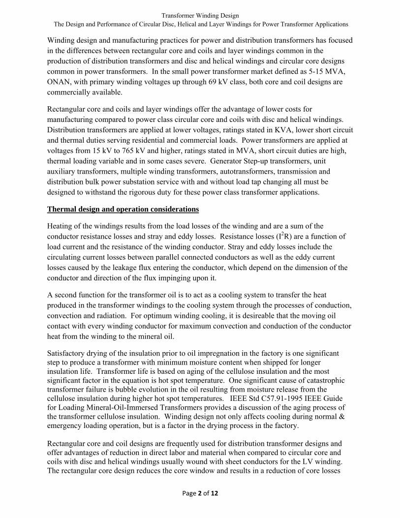
compared to the rectangular core and soil design, it is not as good as a disc and helical circular core and coil construction. An example of a circular core and coil winding assembly utilizing layer windings is shown in the following pictures:
The windings were constructed of rectangular magnet wire with radial cooling spacers inserted between multiples of layers. Reviewing the pictures above, vertical ribs have been used to support the winding conductor and allow vertical flow of oil for winding cooling; it appears that about 60% of the conductors might be in contact with the circulating oil. However, there is no radial spacer allowing oil to contact the conductor between turns. The end rings of the core and coil assembly also include pressboard ribs allowing oil to flow into the coil assembly and exit at the top for winding cooling. IEEE C57.12.00-2006, Paragraph 5.11.1.1 requires all transformers designed and constructed for a maximum of 65 �C average winding temperature rise, and a hot spot temperature rise not to exceed 80 �C And methods to determine the hottest spot winding temperature rises. More detailed guide for determining the hottest spot winding temperature rises can be found in the IEEE 1538-2000 IEEE Guide for Determination of Maximum Winding Temperature Rise in Liquid-Filled Transformers. Detailed calculations require Finite Element Analysis of winding losses to determine the highest loss density location and the magnitude as well as applying the "duct oil temperature" to accurately predict hot-spot temperature. Additional calculations must consider the effect of operation of the DETC (De Energized Tap Changer) and LTC (Load Tap Changer) as these devices result in changes in losses and stray losses and do affect the location of the winding hot spot.
Typical hottest spot temperature rise over average winding temperature, based on tests utilizing fiber optic direct measurements, is lower than 15 �C for Disk type windings. Hot-spot temperatures for this type of windings can be determined within 1.5 �C accuracy based on experiments by WES and other manufacturers.
For layer type windings, it is very difficult to predict and usually higher than disk type unless axial cooling ducts are provided between each layer over the entire circumference of the

Transformer Winding Design The Design and Performance of Circular Disc, Helical and Layer Windings for Power Transformer Applications
Page 5 of 12
winding. Layer type windings typically have much larger volume of conductor and insulation without cooling oil in direct contact to lower the hot-spot temperatures.
The circulation of the oil through the windings into the tank and radiators is the process that removes the heat generated by the windings and allows it to be disbursed to the surrounding environment. Oil flows vertically up through the windings in the ducts between the core and LV coil, LV and HV coils, the radial cooling ducts in the HV and LV coils, and along the outer surface of the HV coil. There is also horizontal oil flow between the coil sections for helical and disc windings. This horizontal oil flow can be further directed by the use of oil flow washers that will guide the vertical oil flow horizontally back and forth through the windings.
As the heat is transferred from the windings to the oil, the density of the oil decreases and rises up through the windings continuing to collect even more heat until it finally reaches the top of the windings. The oil over the top of the windings migrates to the tank and radiator surfaces where it cools off and becomes denser and is circulated back to the bottom of the tank and windings where the process repeats.

Transformer Winding Design The Design and Performance of Circular Disc, Helical and Layer Windings for Power Transformer Applications
Page 6 of 12
Circular disc and helical winding design provides maximum contact of the winding conductors with the circulating oil as shown in the picture below:
Every conductor has radial oil flow due to the use of radial spacers for conductor support. Spacer thickness can be changed to allow improved cooling and decreased winding rise or directed oil flow within the winding can be applied to improve the effectiveness of the winding conductor cooling. Installation of outer cylinders also provides improvement of directing the oil flow through the winding. The design also allows the improved drying of the core and coil assembly prior to oil impregnation through the vapor phase process resulting in shipment of a transformer with lower power factor and lower moisture levels in the core and coil insulation.
The core and coil end rings are designed to provide full circumference winding support for all the nested HV and LV windings and also designed to permit oil circulation to the inner windings of the core and coil assembly for cooling.
Non Directed oil flow Directed oil flow

Transformer Winding Design The Design and Performance of Circular Disc, Helical and Layer Windings for Power Transformer Applications
Page 7 of 12
Through Fault - Short Circuit withstand considerations
The windings are subject to both radial and axial forces related to the current and flux interactions. Radial forces in the inner winding (normally the LV winding) are in compression while the outer winding (normally the HV winding) forces are in tension. Design of the windings and bracing must consider the magnitude of these forces and provide adequate strength to withstand them without significant mechanical deformation which could result in a dielectric failure. The picture below is an example of a free bucking mechanical failure of an inner winding resulting from radial forces in compression on the winding. Note, even though there is mechanical failure, there wasn’t a dielectric failure of this winding.
Radial Forces – Buckling (inner Radial Forces – Hoop Stress (outer Coil)
Outward radial forces converted to tensile h
Axial Forces (Applying Left Hand Rule)
Inner Winding Free Bucking
Transformer Winding Design The Design and Performance of Circular Disc, Helical and Layer Windings for Power Transformer Applications
Page 8 of 12
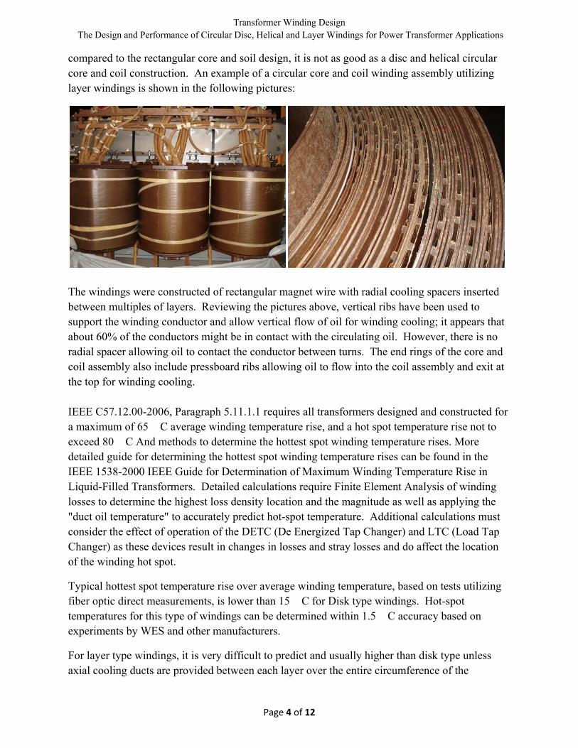
Flux fields are dependent of the balance of the ampere turn distribution of the HV and LV windings. When the ampere turns of the HV and LV windings are equal and balanced, the only forces are radial. DETC taps in the HV windings and LTC operation result in changes in the ampere turn distribution resulting in axial forces. If the HV and LV windings are not aligned axially or one winding is physically shorter than the other, ampere turn balance is significantly affected and axial forces are magnified.
Autotransformers, low impedance, motor starting duty, transformers with multiple voltages by reconnecting the transformer windings in series and parallel configurations, three winding transformers with dual secondary windings for start up or unit auxiliary service at power plants all can result in increased axial and radial forces during a short circuit and require special consideration.
The rectangular core and coil construction presents challenges due to the fact that the windings are not circular, while the radial forces during a fault are attempting to alter the windings from a rectangle to a circular configuration. Adhesion of the epoxy coatings in the paper used for winding layer insulation is crucial to the ability of the winding to withstand these forces without physical changes.
DETC taps are usually specified in the HV winding and with rectangular core and coils and layer windings the inability to provide compensation for the changes in the ampere turn distribution of the HV winding resulting from changing the tap for the DETC in the LV windings result in increasing the axial and radial short circuit forces.
Transformer Winding Design The Design and Performance of Circular Disc, Helical and Layer Windings for Power Transformer Applications
Page 9 of 12
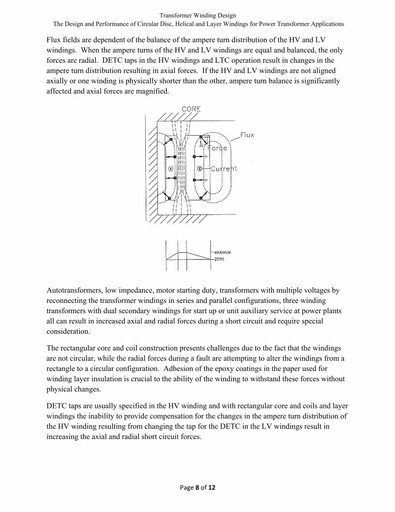
The graph above illustrates that the LV ampere turns are a linear distribution while the HV plot is affected by the position of the DETC. Usually, the DETC is not on A and as the DETC position is changed to a lower voltage rating to meet system voltage operational requirements, short circuit axial forces will increase.
Transformer Winding Design The Design and Performance of Circular Disc, Helical and Layer Windings for Power Transformer Applications
Page 10 of 12
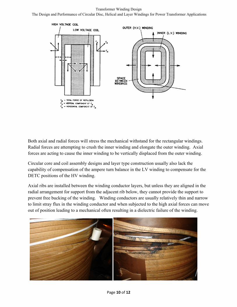
Both axial and radial forces will stress the mechanical withstand for the rectangular windings. Radial forces are attempting to crush the inner winding and elongate the outer winding. Axial forces are acting to cause the inner winding to be vertically displaced from the outer winding.
Circular core and coil assembly designs and layer type construction usually also lack the capability of compensation of the ampere turn balance in the LV winding to compensate for the DETC positions of the HV winding.
Axial ribs are installed between the winding conductor layers, but unless they are aligned in the radial arrangement for support from the adjacent rib below, they cannot provide the support to prevent free bucking of the winding. Winding conductors are usually relatively thin and narrow to limit stray flux in the winding conductor and when subjected to the high axial forces can move out of position leading to a mechanical often resulting in a dielectric failure of the winding.
Transformer Winding Design The Design and Performance of Circular Disc, Helical and Layer Windings for Power Transformer Applications
Page 11 of 12
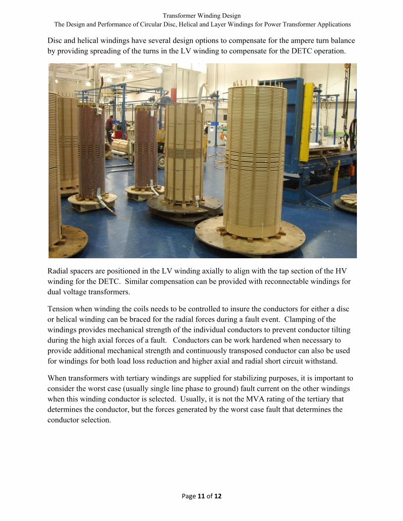
Disc and helical windings have several design options to compensate for the ampere turn balance by providing spreading of the turns in the LV winding to compensate for the DETC operation.
Radial spacers are positioned in the LV winding axially to align with the tap section of the HV winding for the DETC. Similar compensation can be provided with reconnectable windings for dual voltage transformers.
Tension when winding the coils needs to be controlled to insure the conductors for either a disc or helical winding can be braced for the radial forces during a fault event. Clamping of the windings provides mechanical strength of the individual conductors to prevent conductor tilting during the high axial forces of a fault. Conductors can be work hardened when necessary to provide additional mechanical strength and continuously transposed conductor can also be used for windings for both load loss reduction and higher axial and radial short circuit withstand.
When transformers with tertiary windings are supplied for stabilizing purposes, it is important to consider the worst case (usually single line phase to ground) fault current on the other windings when this winding conductor is selected. Usually, it is not the MVA rating of the tertiary that determines the conductor, but the forces generated by the worst case fault that determines the conductor selection.

Transformer Winding Design The Design and Performance of Circular Disc, Helical and Layer Windings for Power Transformer Applications
Page 12 of 12
Mechanical withstand is critical, but we must be review the thermal affect of the short circuit currents on winding temperatures during a short circuit event. Fault winding currents are significantly higher than for normal loads and extremely high winding temperatures are possible unless these conditions are also considered during the conductor selection of the transformer. During the short circuit event, heat transfer through the cooling arrangement is not considered since the thermal time constants of windings are much longer (usually several minutes) than the fault duration. For this reason, the winding temperatures during the fault shall be calculated on the basis of “all heat stored” in the conductor material and turn insulation, per the C57.12.00-2006 Clause 7.4.