transair: advanced air pipe systems - crossco transair...transair: advanced air pipe systems ......
TRANSCRIPT

Transair: Advanced Air Pipe SystemsCompressed Air, Vacuum, Inert Gas
1/2” - 6”
An Energy Efficient
Solution

Within Parker’s eight operating
groups, the company’s engineering
expertise spans the core motion
technologies – electromechanical,
hydraulic and pneumatic – with a
full complement of fluid handling,
filtration, sealing and shielding,
climate control, process control
and aerospace technologies.
The leader in “dry technology”
for the fluid power industry, Parker’s
Fluid Connectors Group is your
single source for high-quality tube
fittings, hose and hose fittings,
thermoplastic tubing, brass
fittings and valves, quick-
disconnect couplings and assembly
tools. The Fluid Connectors Group
serves customers in a broad range
of markets, including Aerial Lift,
Agriculture, Bulk Chemical
Handling, Construction Machinery,
Food & Beverage, Fuel & Gas
Delivery, Industrial Machinery,
Medical, Mining, Mobile, Oil & Gas
and Transportation. Products are
available for shipment 24 hours
a day, supported by 49 manu-
facturing facilities throughout the
world, a global distribution network
and 25 company-owned stocking
service centers. Our commitment
to you is impeccable customer
service. To meet your specific
requirements, we offer a broad
range of programs designed to
reduce your overall operating costs,
streamline manufacturing, improve
productivity, manage inventory,
enhance delivery and address safe-
ty and environmental issues. For
value-added services that
generate value-added solutions,
team up with Parker!
With annual sales exceeding
$12 billion, Parker Hannifin
is the world’s leading
diversified manufacturer of
motion and control technologies
and systems, providing
precision-engineered
solutions for a wide variety
of mobile, industrial and
aerospace markets. Our
products are vital to virtually
everything that moves
or requires control, including
the manufacture and
processing of raw materials,
durable goods, infrastructure
development and all forms
of transport.
Parker Hannifin – the global leader and your partner
1
.
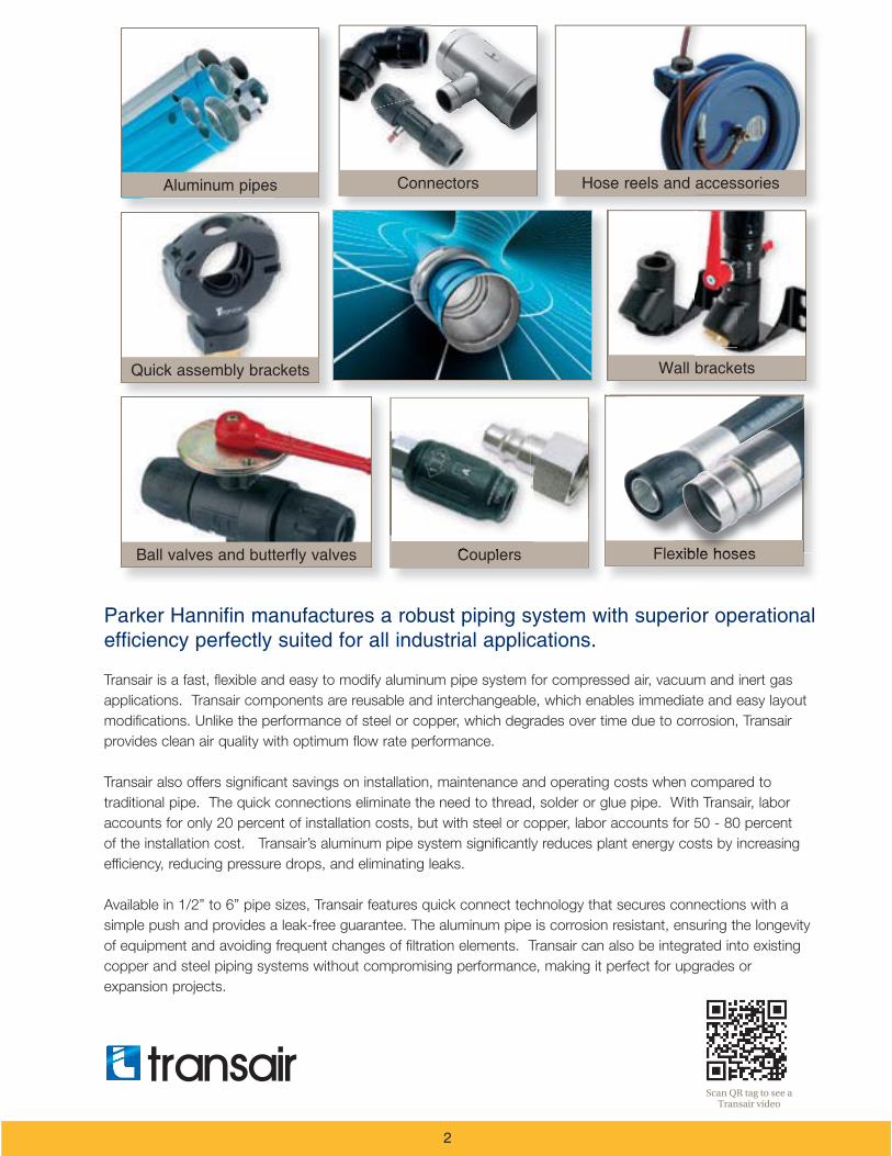
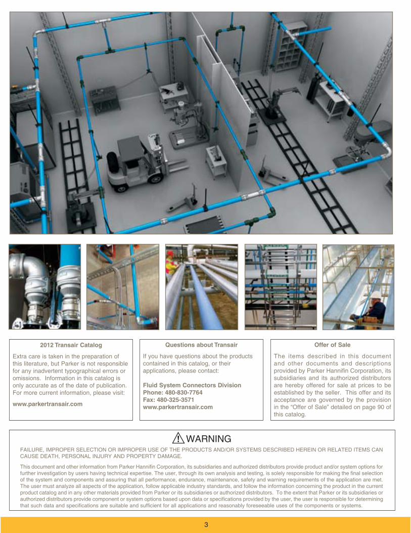
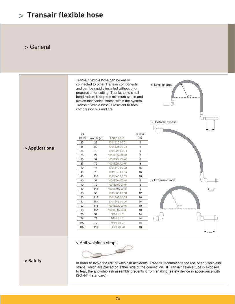
Transair is a fast, flexible and easy to modify aluminum pipe system for compressed air, vacuum and inert gas
applications. Transair components are reusable and interchangeable, which enables immediate and easy layout
modifications. Unlike the performance of steel or copper, which degrades over time due to corrosion, Transair
provides clean air quality with optimum flow rate performance.
Transair also offers significant savings on installation, maintenance and operating costs when compared to
traditional pipe. The quick connections eliminate the need to thread, solder or glue pipe. With Transair, labor
accounts for only 20 percent of installation costs, but with steel or copper, labor accounts for 50 - 80 percent
of the installation cost. Transair’s aluminum pipe system significantly reduces plant energy costs by increasing
efficiency, reducing pressure drops, and eliminating leaks.
Available in 1/2” to 6” pipe sizes, Transair features quick connect technology that secures connections with a
simple push and provides a leak-free guarantee. The aluminum pipe is corrosion resistant, ensuring the longevity
of equipment and avoiding frequent changes of filtration elements. Transair can also be integrated into existing
copper and steel piping systems without compromising performance, making it perfect for upgrades or
expansion projects.
Scan QR tag to see a Transair video
2
Offer of Sale
The items described in this document and other documents and descriptions
subsidiaries and its authorized distributors are hereby offered for sale at prices to be established by the seller. This offer and its acceptance are governed by the provision in the “Offer of Sale” detailed on page 90 of this catalog.
2012 Transair Catalog
Extra care is taken in the preparation of
for any inadvertent typographical errors or omissions. Information in this catalog is only accurate as of the date of publication.
www.parkertransair.com
Questions about Transair
If you have questions about the products
Fluid System Connectors DivisionPhone: 480-830-7764Fax: 480-325-3571www.parkertransair.com
! WARNING
product catalog and in any other materials provided from Parker or its subsidiaries or authorized distributors. To the extent that Parker or its subsidiaries or
3
>
>
>
>
Introduction
Contents
Products catalog
Installation guide
11
32
34
41
4
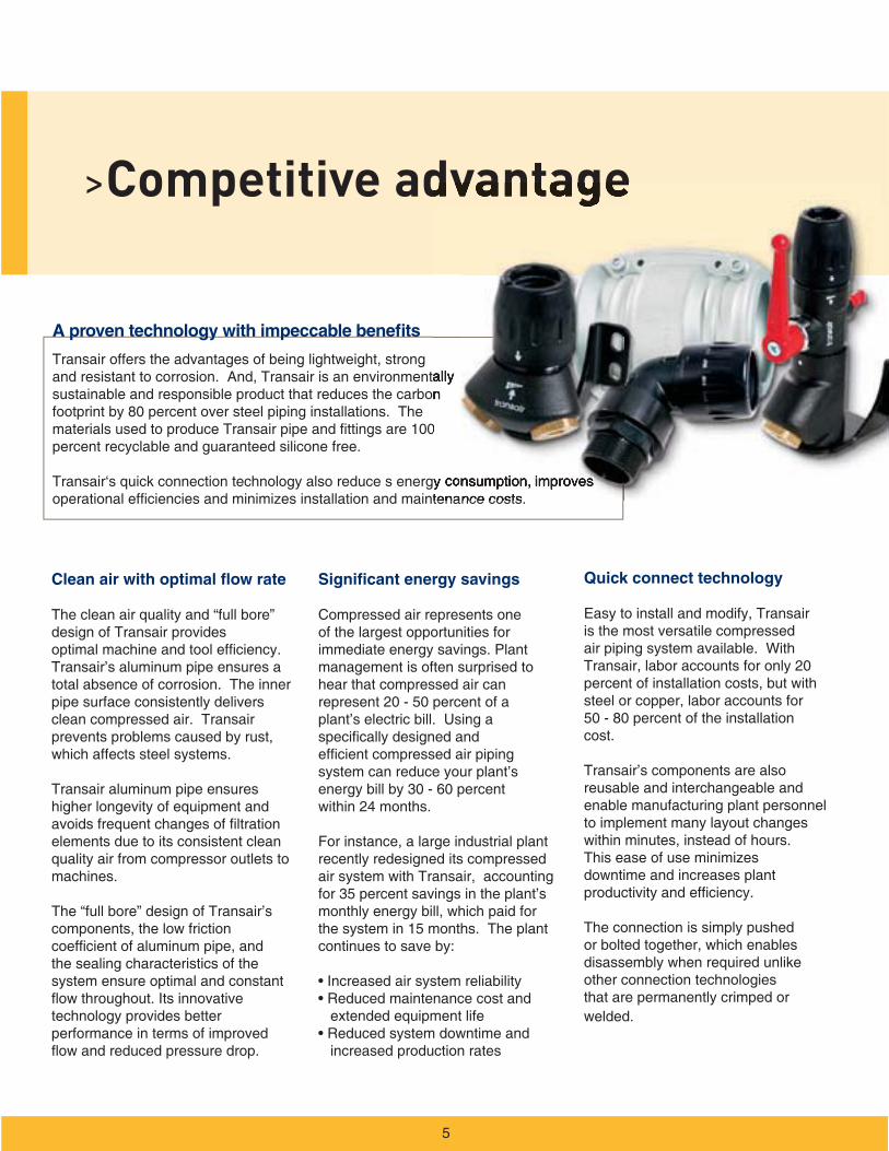
>Competitive advantage
Transair offers the advantages of being lightweight, strong and resistant to corrosion. And, Transair is an environmentally sustainable and responsible product that reduces the carbon footprint by 80 percent over steel piping installations. The
percent recyclable and guaranteed silicone free.
Transair‘s quick connection technology also reduce s energy consumption, improves
Clean air with optimal flow rate
The clean air quality and “full bore” design of Transair provides
Transair’s aluminum pipe ensures a total absence of corrosion. The inner pipe surface consistently delivers clean compressed air. Transair prevents problems caused by rust, which affects steel systems.
Transair aluminum pipe ensures higher longevity of equipment and
elements due to its consistent clean quality air from compressor outlets to machines.
The “full bore” design of Transair’s components, the low friction
the sealing characteristics of the system ensure optimal and constant
technology provides better performance in terms of improved
Significant energy savings
Compressed air represents one of the largest opportunities for immediate energy savings. Plant management is often surprised to hear that compressed air can represent 20 - 50 percent of a plant’s electric bill. Using a
system can reduce your plant’s energy bill by 30 - 60 percent within 24 months.
For instance, a large industrial plant recently redesigned its compressed air system with Transair, accounting for 35 percent savings in the plant’s monthly energy bill, which paid for
continues to save by:
extended equipment life
increased production rates
Quick connect technology
Easy to install and modify, Transair is the most versatile compressed air piping system available. With Transair, labor accounts for only 20 percent of installation costs, but with steel or copper, labor accounts for 50 - 80 percent of the installation cost.
Transair’s components are also reusable and interchangeable and enable manufacturing plant personnel to implement many layout changes within minutes, instead of hours.
downtime and increases plant
The connection is simply pushed or bolted together, which enables disassembly when required unlike other connection technologies that are permanently crimped or welded.
A proven technology with impeccable benefits
5
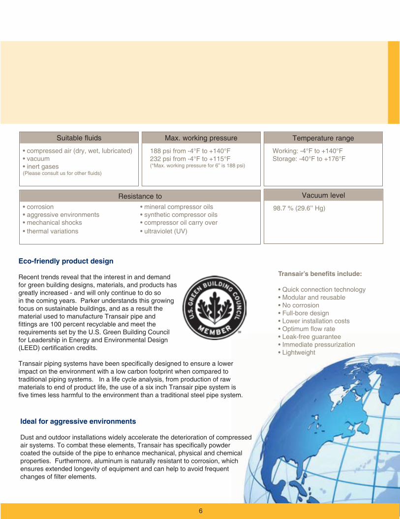
Transair’s benefits include:
Eco-friendly product design
Ideal for aggressive environments
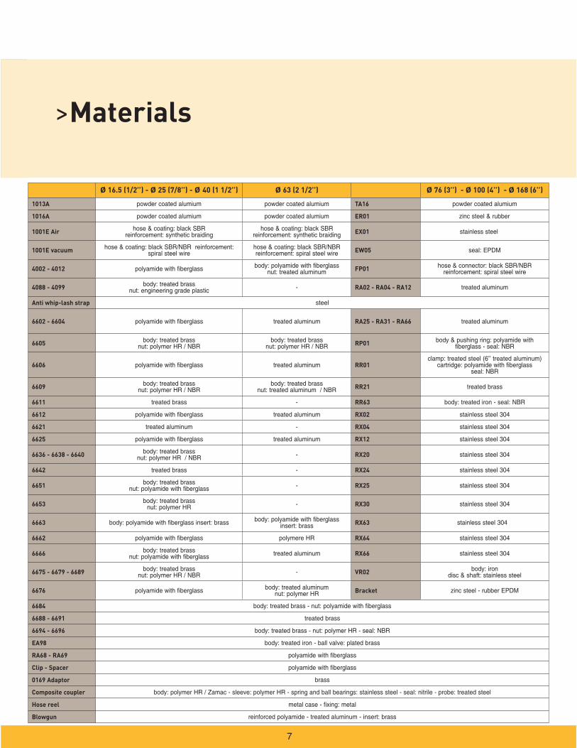
>Materials
Ø 16.5 (1/2’’) - Ø 25 (7/8’’) - Ø 40 (1 1/2’’) Ø 63 (2 1/2’’) Ø 76 (3’’) - Ø 100 (4’’) - Ø 168 (6’’)
1013A TA16
1016A ER01
1001E Air EX01
1001E vacuum EW05
4002 - 4012 FP01
4088 - 4099 - RA02 - RA04 - RA12
Anti whip-lash strap
6602 - 6604 RA25 - RA31 - RA66
6605 RP01
6606 RR01
6609 RR21
6611 - RR63
6612 RX02
6621 - RX04
6625 RX12
6636 - 6638 - 6640 - RX20
6642 - RX24
6651 - RX25
6653 - RX30
6663 RX63
6662 RX64
6666 RX66
6675 - 6679 - 6689 - VR02
6676 Bracket
6684
6688 - 6691
6694 - 6696
EA98
RA68 - RA69
Clip - Spacer
0169 Adaptor
Composite coupler
Hose reel
Blowgun
7
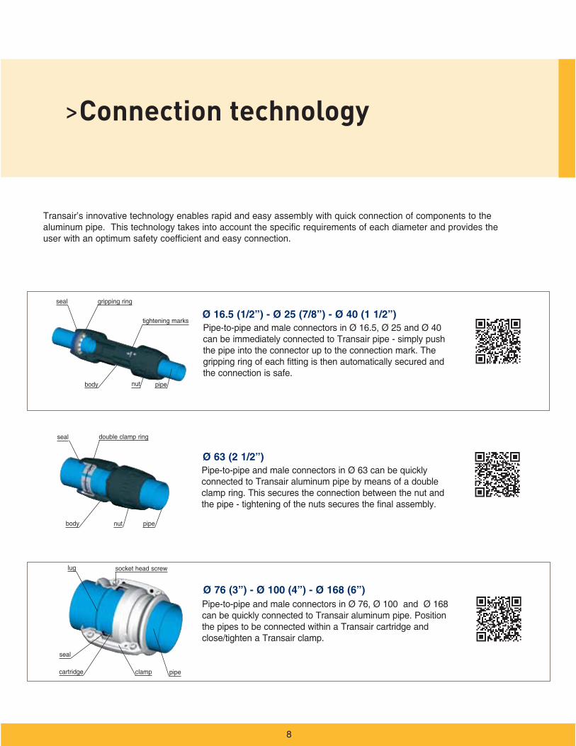
>Connection technology
Ø 16.5 (1/2”) - Ø 25 (7/8”) - Ø 40 (1 1/2”)
Ø 63 (2 1/2”)
Ø 76 (3”) - Ø 100 (4”) - Ø 168 (6”)

>Certifications and guarantees

>Services and tools
Online tools
Services
10
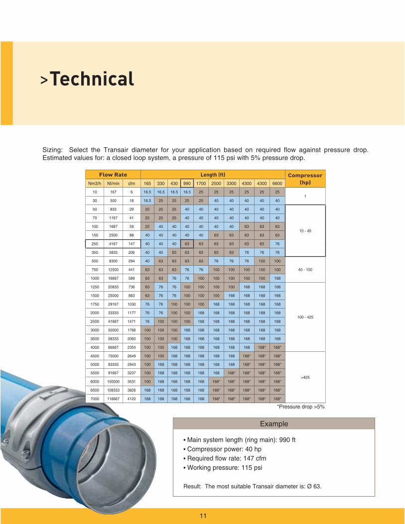
>Technical
11
Flow Rate Length (ft) Compressor (hp)
1
41
441
33333

Maximum flow rate with 1.45 psi pressure drop.
Maximum flow rate with 5% pressure drop
12

Notes>
13
32
34
41
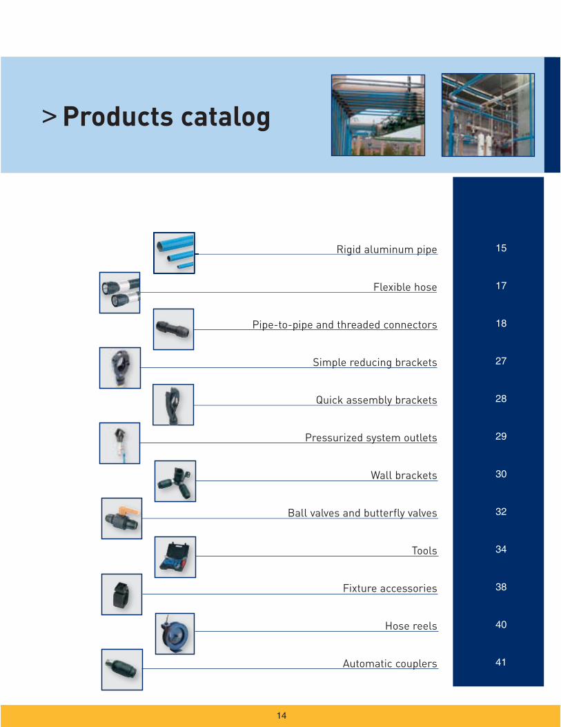
Rigid aluminum pipe
Flexible hose
Pipe-to-pipe and threaded connectors
Simple reducing brackets
Quick assembly brackets
Pressurized system outlets
Wall brackets
Ball valves and butterfly valves
Tools
Fixture accessories
Hose reels
Automatic couplers
> Products catalog
14
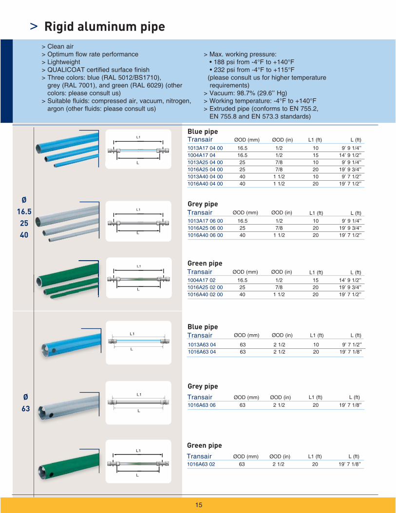
Ø63
Ø16.52540
> Rigid aluminum pipe
Blue pipe
Grey pipe
Green pipe
Blue pipe
Grey pipe
Green pipe
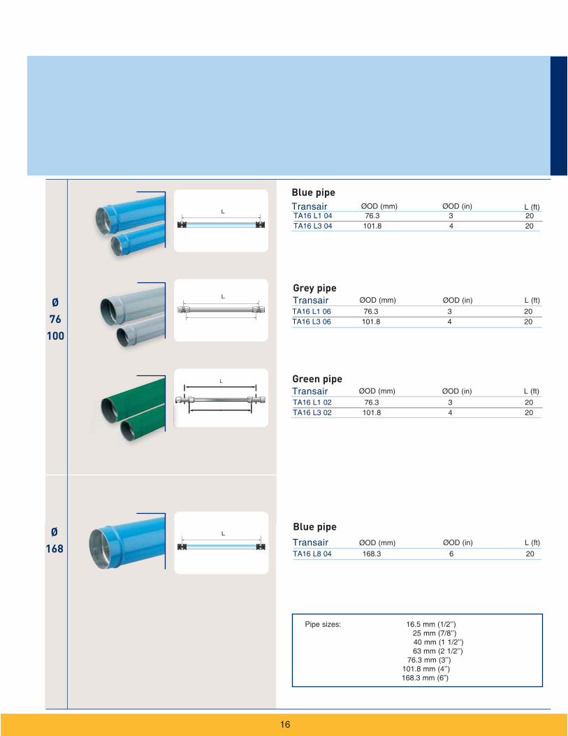
Ø76
100
Ø168
4
Grey pipe
Green pipe
Blue pipe
Blue pipe
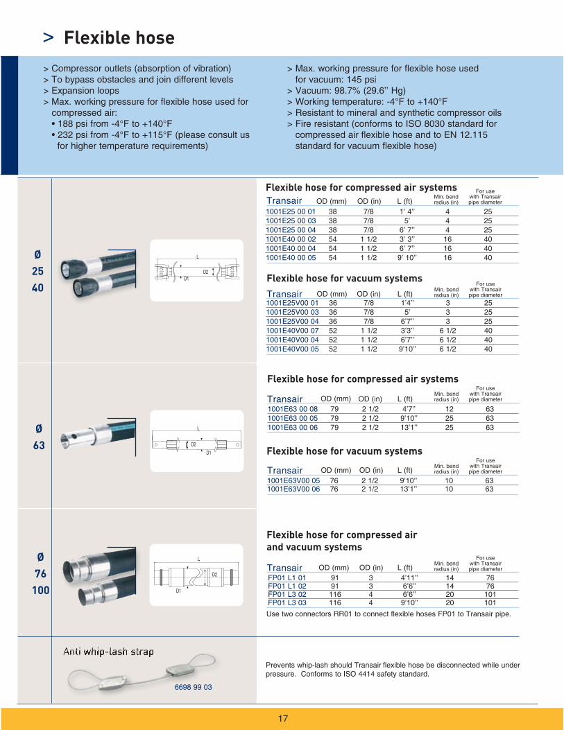
LØ2540
Ø63
Ø76
100
1001E63 00 08 79 2 1/2 4’7’’ 12 631001E63 00 05 79 2 1/2 9’10’’ 25 631001E63 00 06 79 2 1/2 13’1’’ 25 63
1001E63V00 05 76 2 1/2 9’10’’ 10 631001E63V00 06 76 2 1/2 13’1’’ 10 63
1001E25 00 01 38 7/8 1’ 4’’ 4 251001E25 00 03 38 7/8 5’ 4 251001E25 00 04 38 7/8 6’ 7’’ 4 251001E40 00 02 54 1 1/2 3’ 3’’ 16 401001E40 00 04 54 1 1/2 6’ 7’’ 16 401001E40 00 05 54 1 1/2 9’ 10’’ 16 40
1001E25V00 01 36 7/8 1’4’’ 3 251001E25V00 03 36 7/8 5’ 3 251001E25V00 04 36 7/8 6’7’’ 3 251001E40V00 07 52 1 1/2 3’3’’ 6 1/2 401001E40V00 04 52 1 1/2 6’7’’ 6 1/2 401001E40V00 05 52 1 1/2 9’10’’ 6 1/2 40
FP01 L1 01 91 3 4’11’’ 14 76FP01 L1 02 91 3 6’6’’ 14 76FP01 L3 02 116 4 6’6’’ 20 101FP01 L3 03 116 4 9’10’’ 20 101
Transair
Transair
Transair
Transair
Transair
L (ft)Min. bend radius (in)
For use with Transair pipe diameter
Flexible hose for compressed air systems
Flexible hose for vacuum systems
Flexible hose for vacuum systems
Flexible hose for compressed air systems
Use two connectors RR01 to connect flexible hoses FP01 to Transair pipe.
L (ft)
L (ft)
L (ft)
L (ft)
Flexible hose for compressed air and vacuum systems
Min. bend radius (in)
For use with Transair pipe diameter
Min. bend radius (in)
For use with Transair pipe diameter
Min. bend radius (in)
For use with Transair pipe diameter
Min. bend radius (in)
For use with Transair pipe diameter
OD (mm) OD (in)
OD (mm) OD (in)
OD (mm) OD (in)
OD (mm) OD (in)
OD (mm) OD (in)D2
>
17
> Compressor outlets (absorption of vibration) > To bypass obstacles and join different levels > Expansion loops > Max. working pressure for flexible hose used for compressed air:
for higher temperature requirements)
> Max. working pressure for flexible hose used for vacuum: 145 psi
> Vacuum: 98.7% (29.6’’ Hg)
> Resistant to mineral and synthetic compressor oils> Fire resistant (conforms to ISO 8030 standard for
compressed air flexible hose and to EN 12.115 standard for vacuum flexible hose)
Anti whip-lash strap flexible hose be disconnected while under
pressure. Conforms to ISO 4414 safety standard.
Flexible hose
6698 99 03
L
L
D1
D1
D2
D2D1
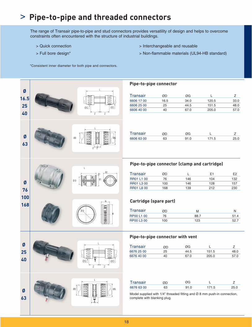
6606 17 00 16.5 34.0 120.5 33.06606 25 00 25 44.5 151.5 48.06606 40 00 40 67.0 205.0 57.0
TransairØ
16.52540
Ø63
Ø76
100168
ØG
L
ØD
Z Z
6606 63 00 63 91.0 171.5 25.0
RR01 L1 00 76 146 104 132 RR01 L3 00 100 146 128 157RR01 L8 00 168 139 212 230
Transair
Transair
L
E2E1
Ø D E1
Ø D
N
M
ØD ØG ZL
ØD ØG ZL
ØD L E1 E2
RP00 L1 00 76 88.7 51.4RP00 L3 00 100 123 52.7
Transair ØD M N
L
Z Z
ØGØD
Ø63
Ø2540 ØG
L
ØD
Z Z
6676 63 00 63 91.0 171.5 25.0
Transair
Transair
ØD ØG ZL
ØD ØG ZLL
ØGØD
Z Z
6676 25 00 25 44.5 151.5 48.06676 40 00 40 67.0 205.0 57.0
>
18
Pipe-to-pipe and threaded connectors
> Quick connection
> Full bore design*
> Interchangeable and reusable
> Non-flammable materials (UL94-HB standard)
The range of Transair pipe-to-pipe and stud connectors provides versatility of design and helps to overcome constraints often encountered with the structure of industrial buildings.
*Consistent inner diameter for both pipe and connectors.
Pipe-to-pipe connector
Pipe-to-pipe connector (clamp and cartridge)
Cartridge (spare part)
Pipe-to-pipe connector with vent
Model supplied with 1/4” threaded fitting and Ø 8 mm push-in connection, complete with blanking plug.

Ø63
Ø76
100
Ø168
Ø16.5
to63
ØGL
Z
ØD
Z
H
CE
JZ2
Z1
L
ØDØG
6602 17 00 16.5 34.0 58.0 31.06602 25 00 25 44.5 68.0 40.06602 40 00 40 67.0 107.0 62.0
Transair
6602 63 00 63 91.0 122.0 61.0
RA02 L8 00 168 269.2 185
Transair
Transair
RX02 L1 00 76 227 189RX02 L3 00 100 278 221
Transair
Ø D
Ø D
90°H
H
ØD ØG ZL
ØD H
H
Ø16.52540
ØD
ØD
ØG Z
Z
L
Z
Z
Z
Z
Z
ØDØG
L
L
6609 17 14 16.5 1/4’’ 9.5 17 34 34 58 31 41.26609 17 22 16.5 1/2’’ 15 23 34 34 58 31 46.56609 25 22 25 1/2’’ 15 27 44.5 45.5 69.5 40.5 53 6609 25 28 25 3/4’’ 15 27 44.5 45.5 69.5 40.5 53 6609 25 35 25 1’’ 16 36 44.5 45.5 69.5 40.5 55 6609 40 35 40 1’’ 16 41 67 68.5 107 62 75 6609 40 43 40 1 1/4’’ 21.5 50 67 68.5 107 62 816609 40 50 40 1 1/2’’ 24.5 50 67 68.5 107 62 816609 40 44 40 2’’ 23 60 67 68.5 107 62 816609 63 41 63 2 1/2’’ 27 80 91 91 124 61 1066609 63 46 63 3’’ 30 95 91 91 124 61 83
TransairØOD (mm) C L Z1 Z2ØJØGHE
>
19
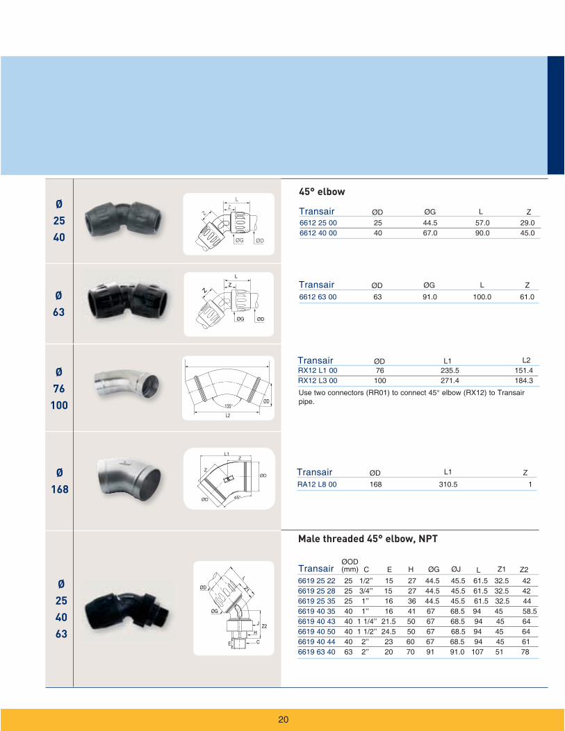
Pipe-to-pipe and threaded connectors
90° elbow
Male threaded 90° elbow, NPT
Use two connectors (RR01) to connect 90° elbow (RX02) to Transair pipe.
Use two connectors (RR01) to connect 90° elbow (RA02) to Transair pipe.
Ø63
ØDØG
L
Z
ØG
ØD
Z2
CE
H
J
ØG
L
Z
ØD
ZØ2540
Ø76
100
Ø168
Ø254063
Ø63
ØG
ØG
C ØJØGH
Male threaded 45° elbow, NPT
45° elbow
Ø76
100
Ø63
Ø16.52540
Ø76
100
Ø63
Ø162540
H
ØG
LZ1
ØDHZ2
Z1
Ø63
Ø16.52540
Ø63
Ø76
100168
Ø76
100
Ø168
ØG
L
Z1
ØD2
ØD1Z2
H
H
H
H
>
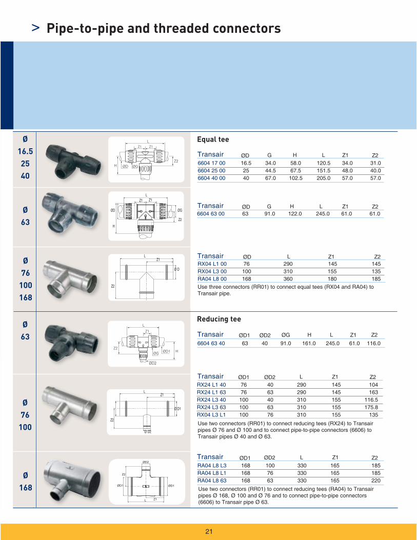
21
Equal tee
Reducing tee
Pipe-to-pipe and threaded connectors
ØG ØD2ØD1
Z
L
L
ØGØD2
Ø76
100
Ø168
Ø16.52540
Ø63
Ø76
100
C
Ø 6
3
Ø 40
61
116
2580
Ø 63
Ø 40
22
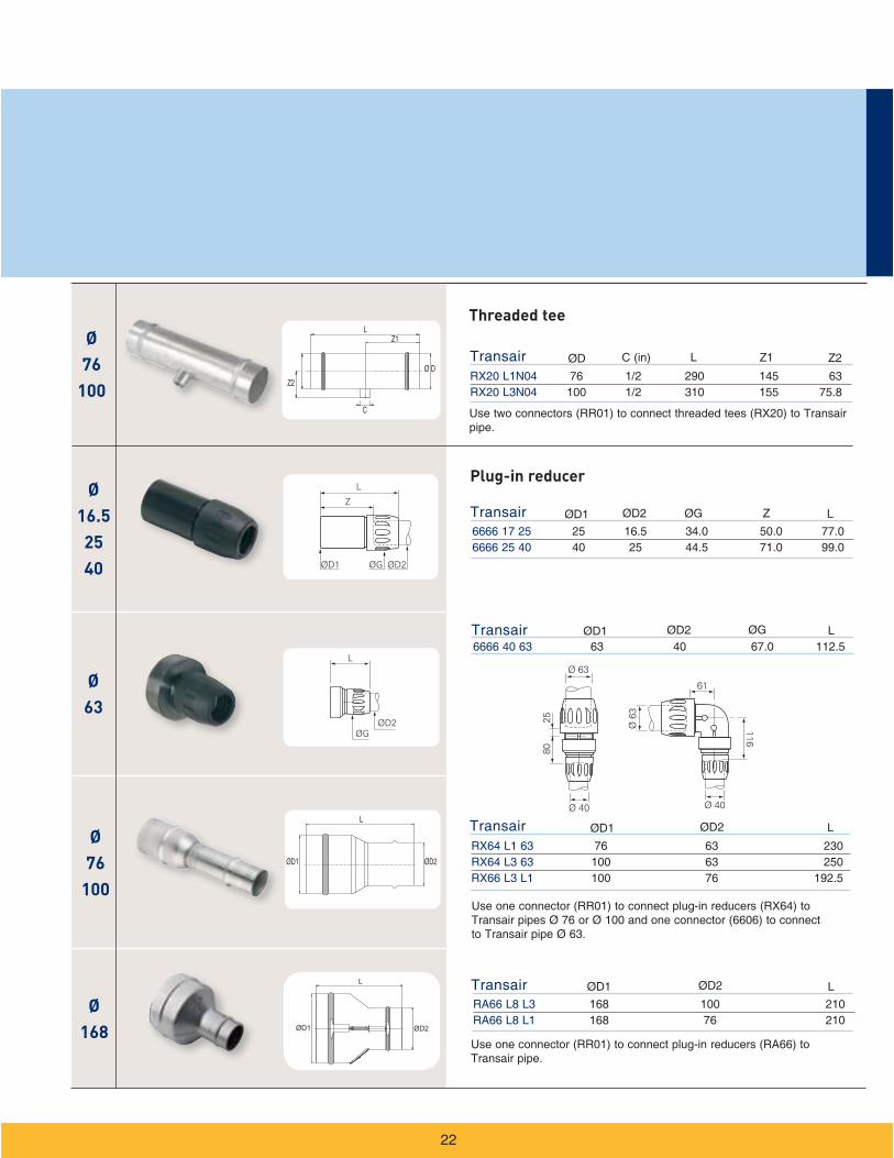
Threaded tee
Plug-in reducer
Ø16.52540
Ø63
Ø76
100
Ø168
6625 17 00 16.5 25.5 34.0 45.5 62.5
6625 25 00 25 33.0 44.5 47.0 75.0
6625 40 00 40 34.5 67.0 55.0 98.5
Transair ØD ØGE H L
6625 63 00 63 31.0 91.0 74.0 111
RA25 L8 00 168 117
Transair
Transair
ØD
ØD
ØGE H L
L
RX25 L1 00 76 99.6
RX25 L3 00 100 107.4
Transair ØD L
ØG
E
ØD
L
H
L
Ø D
L
ØG
H
Ø16.52540
>
23
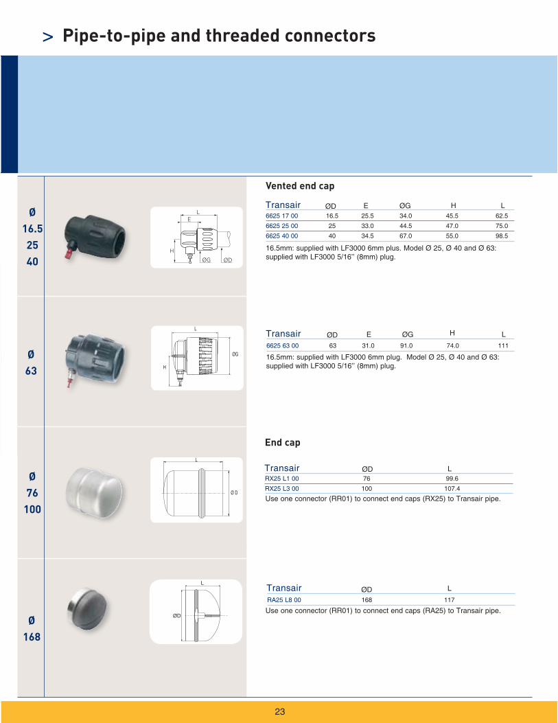
Pipe-to-pipe and threaded connectors
Vented end cap
Use one connector (RR01) to connect end caps (RX25) to Transair pipe.
Use one connector (RR01) to connect end caps (RA25) to Transair pipe.
16.5mm: supplied with LF3000 6mm plus. Model Ø 25, Ø 40 and Ø 63: supplied with LF3000 5/16’’ (8mm) plug.
16.5mm: supplied with LF3000 6mm plug. Model Ø 25, Ø 40 and Ø 63: supplied with LF3000 5/16’’ (8mm) plug.
End cap
Ø16.52540
ØG
E
ØD
C
H
Ø63
Ø25 40
H
C
C
ØG H
C HØ G
H
C
ØG
55
407
H
Z
L
MN
20
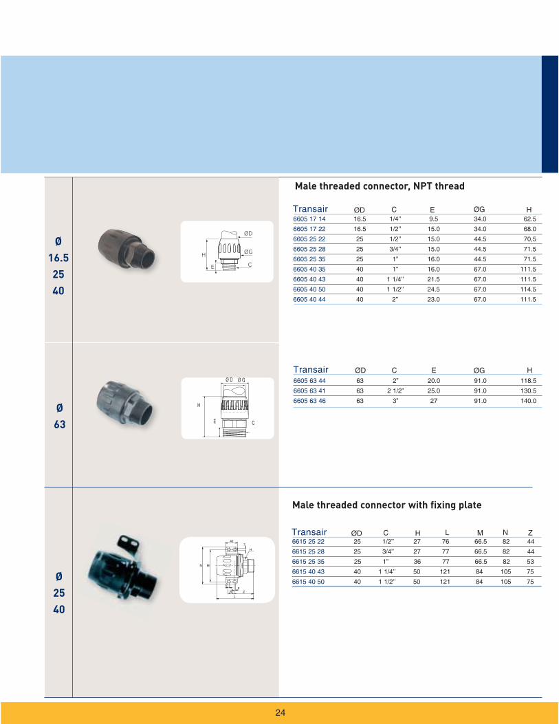
Male threaded connector, NPT thread
Male threaded connector with fixing plate
Ø16.52540
Ø16.52540
Ø76
ØD
C
L
H
H
H
H
C
C ØG H
Ø16.5
to 63
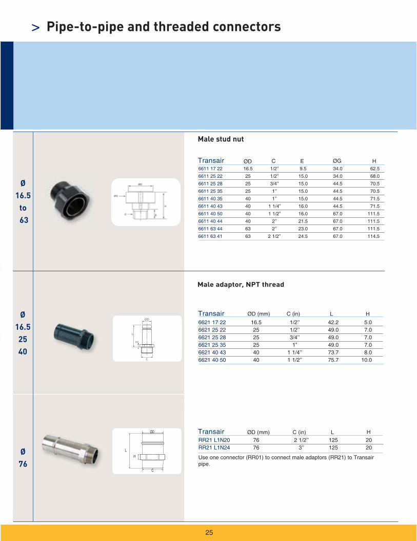
> Pipe-to-pipe and threaded connectors
Male adaptor, NPT thread
Male stud nut

Ø2540
L1
Ø12
L2 N N N
ØG
ØD
L
Z Z
LZ
NC
L2
46
N N
L1
N N
NM
19,5
ZH
K
ØD
6651 25 12 04 25 44.5 271.0 151.0 23.0 35.0 107.06651 40 12 04 40 67.0 400.0 204.0 27.0 50.0 150.0
6653 25 22 06 25 1/2’’ 463 300 25 448 50 204 74 86.56653 40 22 06 40 1/2 ‘‘ 526 310 25 469 50 217 83 104.5
Transair
Transair
ØD
ØD
L
L
G
C
Z
N Z H M
L1
L1
L2
L2
N
K
Ø76
100168
RX30 L1 00 76 65 185 145 18 10 75RX31 L1 00 76 80 200 160 18 10 75RX30 L3 00 100 100 220 180 18 10 75RX31 L3 00 100 100 228.5 190.5 19 12.7 75RX31 L8 00 168 150 279 240 22 25 100
Transair ØD D1
EW05 L1 00 76 RX30/RX31 L1 00EW05 L3 00 100 RX30/RX31 L3 00EW05 L8 00 168 RA31 L8 00
Transair ØD
EW06 00 01 5/8’’ 60 EW06 00 05 M20 80
Transair C L
D2D3
D1 Ø D
LE
D2 D3 E LDN
26
4 port manifold
6 port manifold
Supplied with four Ø12 mm plugs.
Supplied with 1/2’’ NPT ports.
Flange
RX30 dimensions conform to EN 1092-1 standard and the RX31 dimensions conform to ANSI B16.5 standard.
Flange gasket
Flange bolt kit
Contains eight bolts and eight nuts.
For use with flange reference
RA69 25 17 25 16.5 92 34 37 52 47.5RA69 40 25 40 25 117 44.5 37 74 61
Transair ØD1 ØD2 M G L N Z
Ø2540
Ø76
100
Ø168
Ø2540
RR63 L1N08 76 1” M12 50 137RR63 L3N08 100 1” M12 80 137
RR63 L8N12 168 1 1/2” 16 90 235RR63 L8N16 168 2” 16 103 235
Transair
Transair
ØD
ØD
C1
C1
C2
C2
E
E
L
L
RA68 25N04 25 1/2’’ 37 52 86RA68 40N04 40 1/2’’ 37 74 100
Transair ØD C L N M
ØD1
ØG
L N
Z
M
ØD2 ØD2
LC1
E
C2
N
ØD
L
M
C
>
27
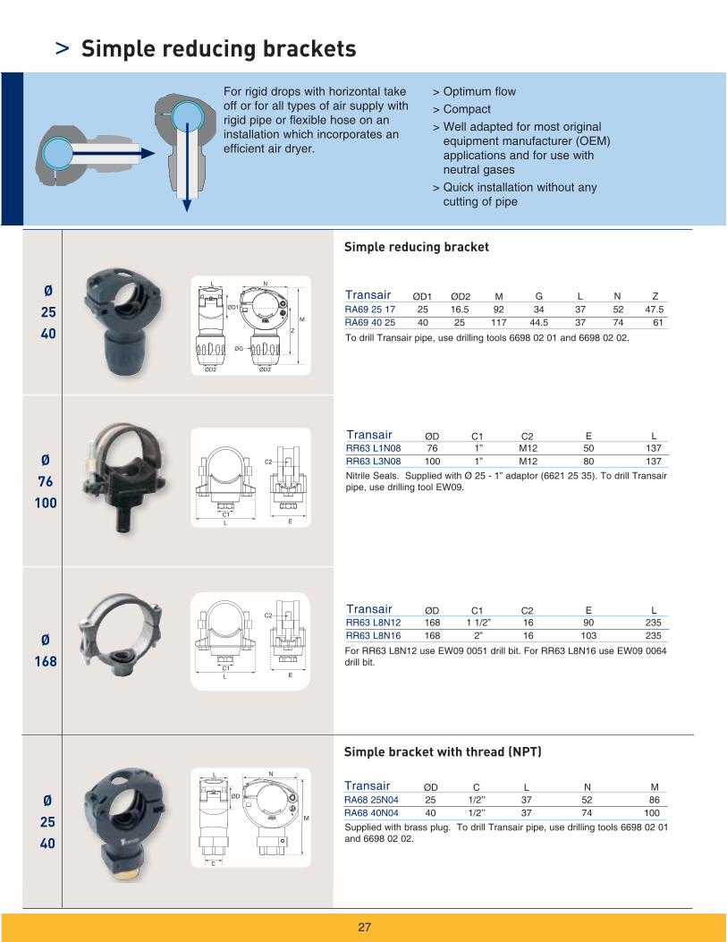
Simple reducing brackets
Simple reducing bracket
Simple bracket with thread (NPT)
To drill Transair pipe, use drilling tools 6698 02 01 and 6698 02 02.
Nitrile Seals. Supplied with Ø 25 - 1” adaptor (6621 25 35). To drill Transair pipe, use drilling tool EW09.
Supplied with brass plug. To drill Transair pipe, use drilling tools 6698 02 01 and 6698 02 02.
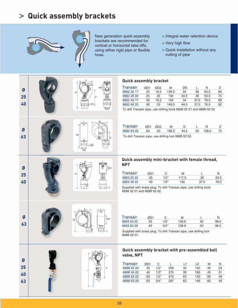
For rigid drops with horizontal take off or for all types of air supply with rigid pipe or flexible hose on an installation which incorporates an efficient air dryer.
> Optimum flow
> Compact
> Well adapted for most original equipment manufacturer (OEM) applications and for use with neutral gases
> Quick installation without any cutting of pipe
For RR63 L8N12 use EW09 0051 drill bit. For RR63 L8N16 use EW09 0064 drill bit.
Ø2540
Ø254063
Ø63
Ø2540
Ø63
D2
ØG
L N
MZ
ØD1
N
L2
L
C
L1
ØD1
M
C N
N
C N
C N
> Quick assembly brackets
Quick assembly bracket
Quick assembly mini-bracket with female thread, NPT
Quick assembly bracket with pre-assembled ball valve, NPT
N
C E N
Ø63
Ø2540
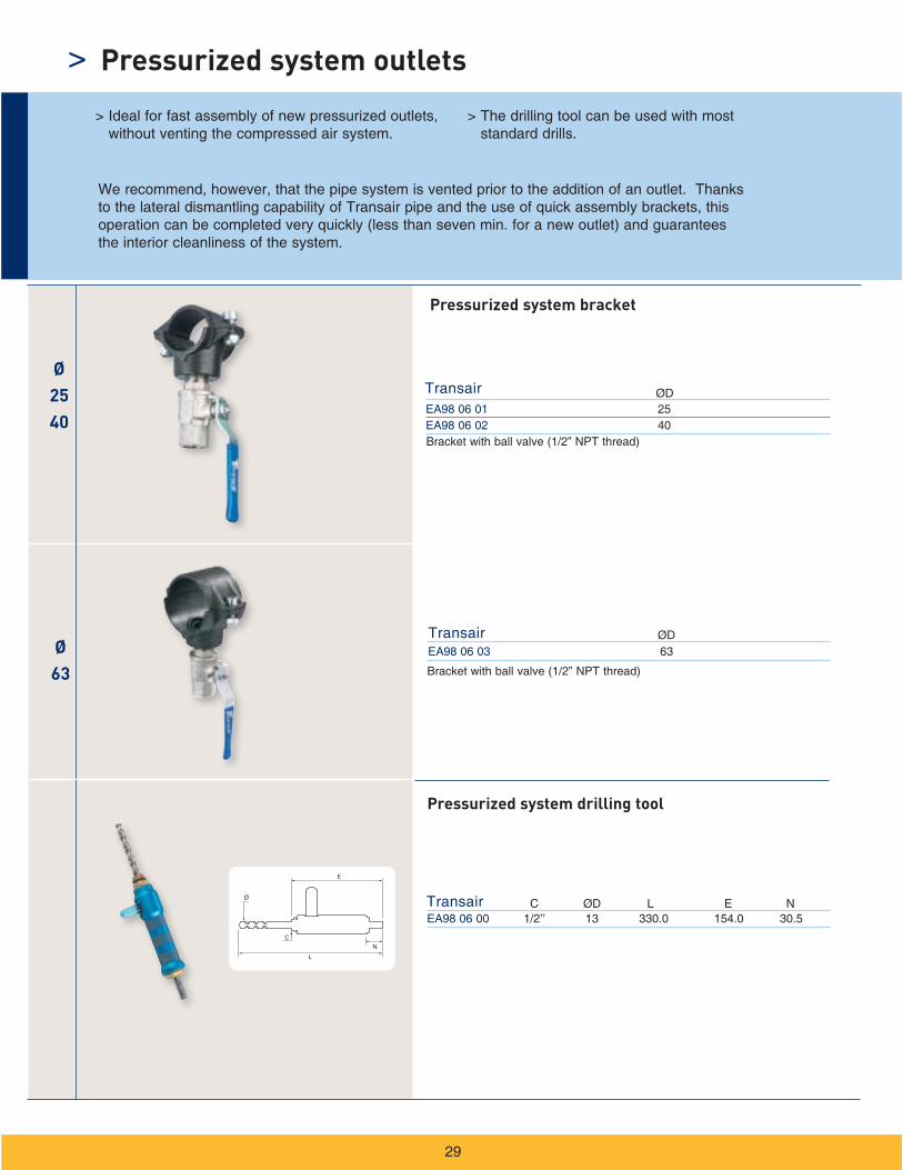
> Pressurized system outlets
Pressurized system bracket
Pressurized system drilling tool
H
K N C2
ØG
ØD
C1
66.5
19,5
C346K
N
19,5
M
H
C1
C2
N
K
46 C2C1
H19,5
66,5
Z
ØD
N
M
C1
C2
H
K
19,5
C3
66,5
Z19,5
N
K
46
H
C2 C1
ØD
C246 C3
C1
H
K
N
19,5
M
C1 H K N
C1 C2 H K N
C2
C1 H K NC2
C3
C1
C1
C2
C2
H
H
K
K
N
N
C3
C3
Ø16.525
C1 H K NC2
C1 H K NC2
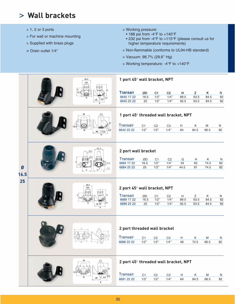
> Wall brackets
>
1 port 45 wall bracket, NPT
2 port 45 wall bracket, NPT
2 port wall bracket
1 port 45 threaded wall bracket, NPT
2 port threaded wall bracket
2 port 45 threaded wall bracket, NPT
Transair ØD C1 H Z K N
Transair C1 C2 H K N
6636 28 22 3/4’’ 1/2’’ 1/4’’ 64 84.5 66.5 82
6638 25 22 25 1/2’’ 1/4’’ 173 142 84.5 108.5
6696 25 22 25 1/2’’ 1/4’’ 92.5 63.5 84.5 82
C2
C3 M
H Z NK
Transair
Transair
Transair
Transair
ØD
ØD
ØD
ØD
C1
C1
C1
C1
H
H
H
Z
Z
Z
K
K
K
N
N
N
C2
C2
C2
C2
6694 17 22 16.5 1/2’’ 1/4’’ 148.5 123 84.5 69.56694 25 22 25 1/2’’ 1/4’’ 173 142 84.5 108.5
6675 17 22 16.5 1/2’’ 1/4’’ 137 111.5 74.5 69.56675 25 22 25 1/2’’ 1/4’’ 163 132 74.5 108.5
6679 17 22 16.5 1/2’’ 1/4’’ 148.5 123 84.5 69.56679 25 22 25 1/2’’ 1/4’’ 173 142 84.5 108.5
Transair ØD C1 H Z K NC2
Ø25
Ø16.525
C1C2
KN
19,5
Z
66,5
46
H
ØD
L
N
K
C3C2
C1
46
19,5H
HZ
C246
K
C1
N
ØD
46C2C1
N
K
HZ
ØD
H
K46 C2
ØD
C1
N
Z
46 C2
K
C1
N
HZ
ØD
>
31
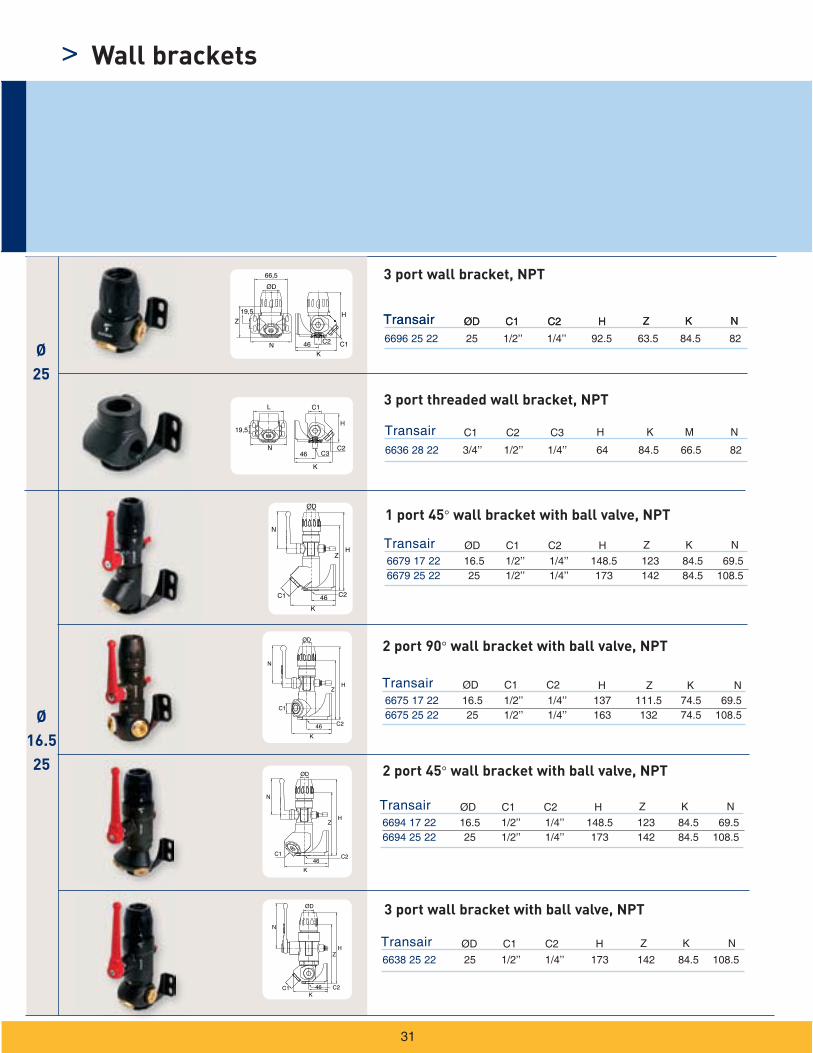
Wall brackets
3 port wall bracket, NPT
2 port 45° wall bracket with ball valve, NPT
3 port wall bracket with ball valve, NPT
3 port threaded wall bracket, NPT
1 port 45° wall bracket with ball valve, NPT
2 port 90° wall bracket with ball valve, NPT
ØG
L
Z2Z1
ØD
N
Ø76
100
Ø63
Ø16.525
N
ØG
Z Z
L
ØD
N
ØG
L
N
ØD
Z1 Z2
N
N
Ø40
N
B RA K
32
Double female, vented
Lockable valve, vented
Double female valve
Ball Valve
Ball valves>
Ø40
Ø76
100
Ø168
ØG
L
Z Z
ØD
Ø4 Ø4
H K
L
K1
H K K1
Remote control shut-off valve
Butterfly valve
Pilot kit
DN
DN
N
N
E
E
>
33
Valves
Ø76
100
Ø63
Ø162540 Ø
25to40
Ø16.5
to168
Ø63
Ø16.5
to63
H
H
H
L
H
H
34
Tool case
Pipe cutter
Drilling jig for rigid aluminum pipe
Drilling jig for rigid aluminum pipe
Tools>
Ø25
Ø40 63
Ø16.52540
EW09 00 22 22 12 71 Ø 40 - 63mmEW09 00 30 30 12 71 Ø 76 - 100mmEW09 00 51 51 12 110 Ø 168mmEW09 00 64 64 12 110 Ø 168mm
Ø40 to
168
6698 02 02 16 12 71 Ø 25mm
6698 02 01 22 12 71 Ø 40 - 63mm
Transair ØD1 ØD2 H
6698 04 02 140Transair L
6698 04 01 64
Transair H
Transair ØD1 ØD2 H
Transair ØD1 ØD2 H
Ø16.5
to 168
>
35
Tools
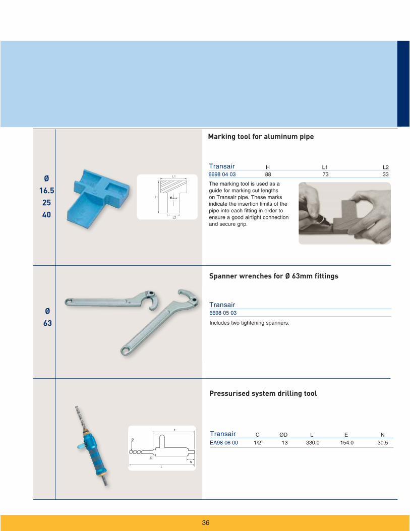
Drilling tool 6698 02 02 is required to install Ø 25 Transair brackets. Can be used with all types of drills.
Drilling tool for aluminum pipe
Deburring tool for aluminum pipe
Chamfer tool for aluminum pipe
Drilling tool 6698 02 01 is required to install Ø 40 and Ø 63 Transair brackets. It is also used to create the two holes needed for double-clamp ring connectors when cutting to length Ø 63 Transair pipe.
For Transair pipe
Drilling tool EW09 is required to install Transair simple reducing brackets. After drilling, it is important to deburr and clean the pipe.
For Transair pipe
For Transair pipe
For 16.5, 25 and 40mm.
Ø63
H
L1
L2
H
C E N
Ø16.52540
Marking tool for aluminum pipe
Spanner wrenches for Ø 63mm fittings
Pressurised system drilling tool
Ø63
Ø76
100
Ø16.52540
Ø76
100168
14
V
E1 E2
14
E1
E2
V
> Tools
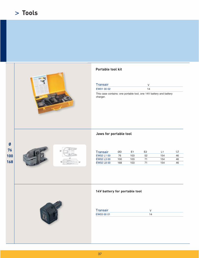
Portable tool kit
Jaws for portable tool
14V battery for portable tool
C H1C
L
ØD
K
HH1
C
L
ØD
K
HH1
C
C
H K
C H1 H K
Ø16.52540
Ø63
Ø76
100168
Ø76
100
C
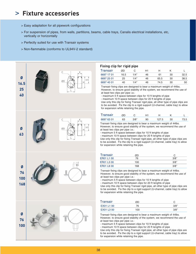
Fixing clip for rigid pipe
Fixture accessories>
H H1
ØD
L K
H1H K
L
L1
H
L
H
H
H
90mm
46mm
44mm
Ø63 Ø40
Ø16.5
to 63
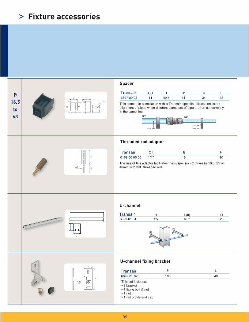
Spacer
U-channel fixing bracket
H
C1E
HC1 E
Threaded rod adaptor
U-channel
Fixture accessories>

L
H
ØD
L
H
ØD
6698 11 11 3/8 250 251 300
Transair H L
6698 11 12 3/8 250 251 390
Transair H L
50 ft
25 ft
>
40
Hose reels > Optimize productivity and the safety of your
work area > Prevent hose damage occurring on the
workshop floor > Maximum working pressure, dependant on the
model:
> Working temperature: -4°F to +14°F
Light series hose reel
Hose clutch with free returnOutlet connection 1/4 male - 3/8’’ inlet
Hose i.d. (in)
Light series hose reel
Hose clutch with free returnOutlet connection 1/4 male - 3/8’’ inlet
Hose i.d. (in)Max. Pressure
(psi)
Max. Pressure (psi)
Hose reels
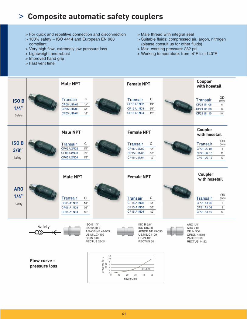
ARO1/4’’
ISO B3/8’’
ISO B1/4’’
Safety
41
Flow curve – pressure loss
Male NPT Female NPT Coupler with hosetail
Male NPT Female NPT Coupler with hosetail
Male NPT Female NPT Coupler with hosetail
Safety
Safety
Safety
Composite automatic safety couplers>
13
C
C
C
C
C
C
flow (SCFM)
12108642
0 10 20 30 40 50
ssol er
usserp
isp
ni
0
Cv=1.24•
••
•• •
•
•
ISO B 1/4’’
ISO B 3/8’’
ARO1/4’’
100/101
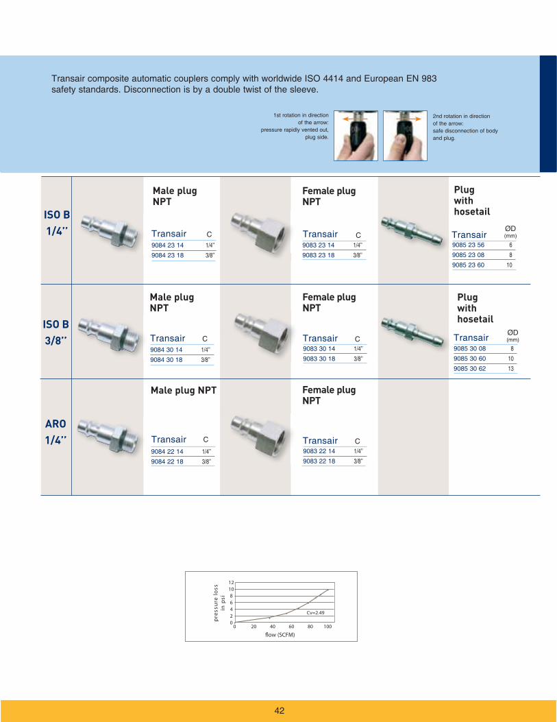
42
Male plug NPT
Female plug NPT
Plug with hosetail
Male plug NPT
Female plug NPT
Male plug NPT Female plug NPT
Plug with hosetail
13
C
C
C
C
C
C
flow (SCFM)
ssol er
usserp
isp
ni
12108642
0•
20 40 60 80 1000
Cv=2.49•
••
•• •
•

> Notes
43
44
> Installation guide
Essential instructions
Aluminum pipe
Pipe-to-pipe connectors
Quick assembly brackets
Flexible hose
Fixture accessories
Practical information
Transair in use
Index
Offer of sale
44
> Installation
> General
> Pressurizing the system
> Transair pipe and hoses
> Expansion / contraction
> Component assembly
> Transair installations - situations to avoid
>
Transair aluminum pipe
> Presentation
> Applications

> Connection indicator
> Drilling locator: mark lines for correct drilling
> Marking
>
> Ø 16.5 - Ø 40
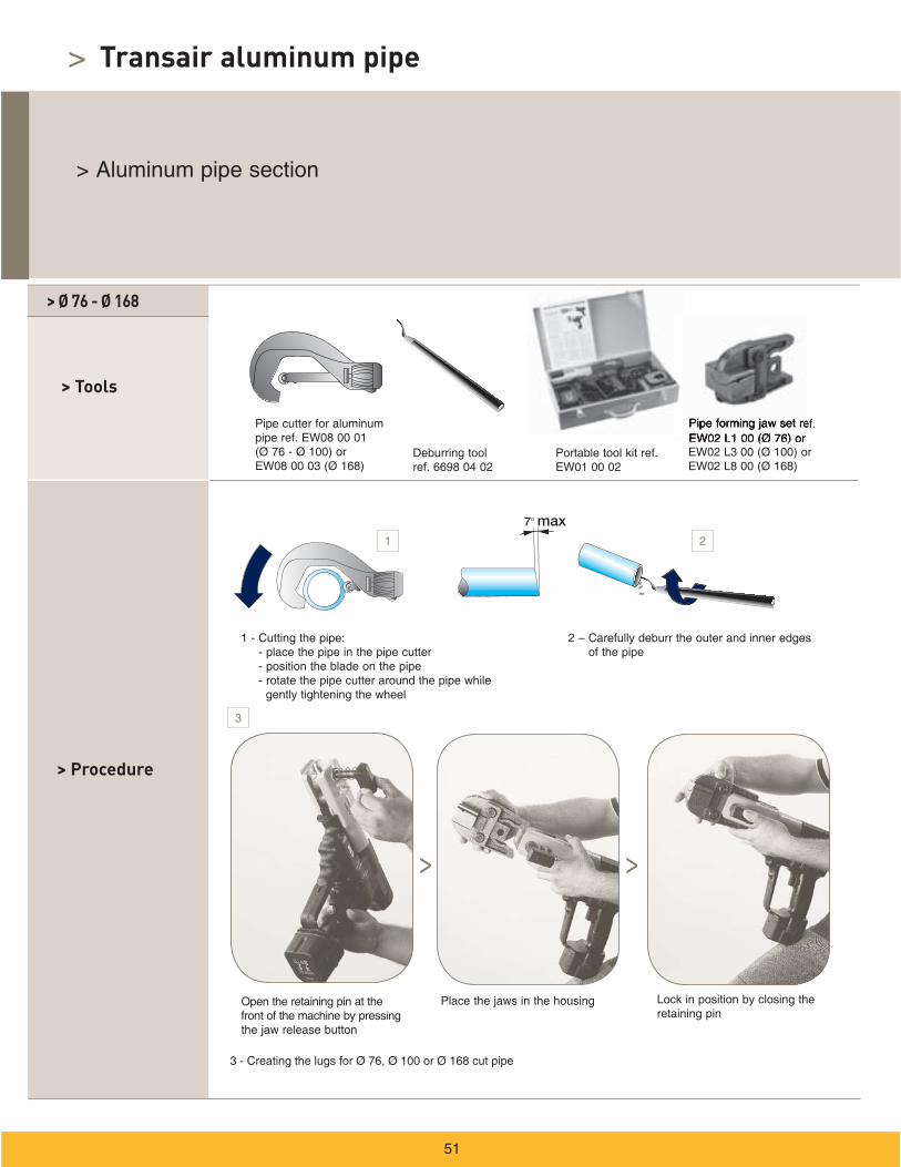
> Procedure
> Tools
Transair aluminum pipe
1 2
3 4
> Tools
> Procedure
> Ø 63
4
1 32
>
> Ø 76 - Ø 168
> Procedure
> Tools
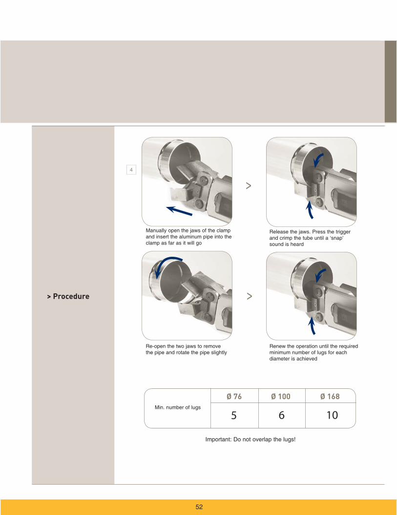
Transair aluminum pipe
1
3
> >
2
> Procedure
Ø 76 Ø 100 Ø 168
4
>
>
5 6 10
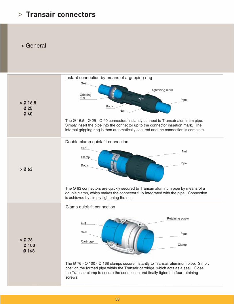
> Transair connectors
> Ø 16.5 Ø 25 Ø 40
> Ø 63
> Ø 76 Ø 100
Ø 168
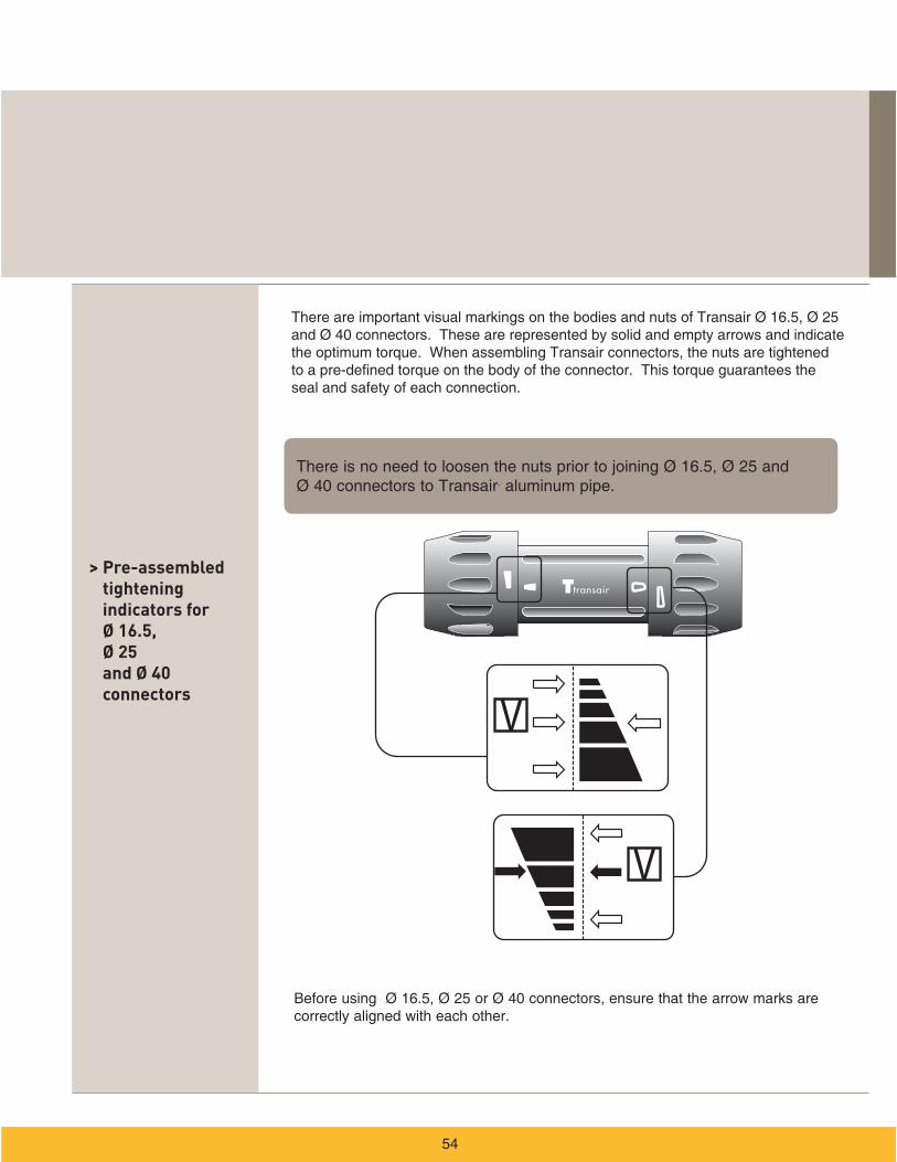
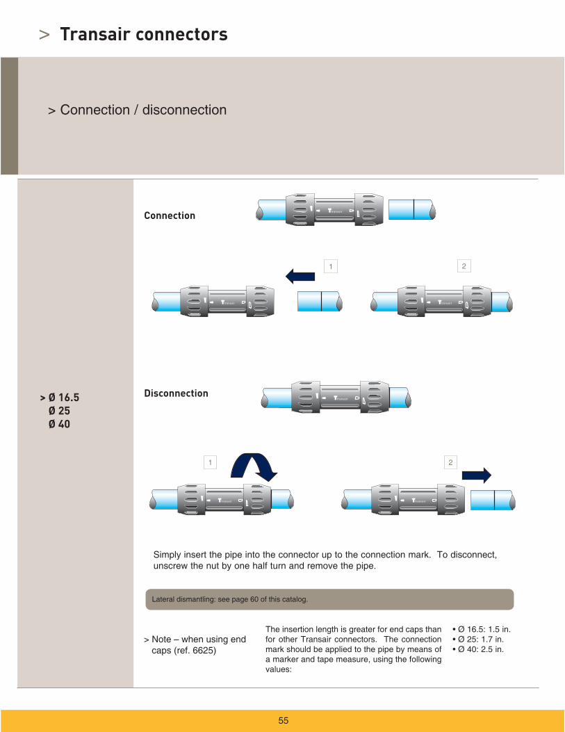
> Pre-assembled tightening indicators for Ø 16.5, Ø 25 and Ø 40 connectors
.
> Transair connectors
> Ø 16.5 Ø 25 Ø 40
Connection
Disconnection
1 2
1 2

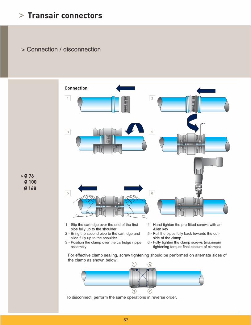
> Ø 63
Connection
Disconnection
1 2
3 4
> Transair connectors
> Ø 76 Ø 100
Ø 168
Connection
1
1 2
3 4
4
3 2
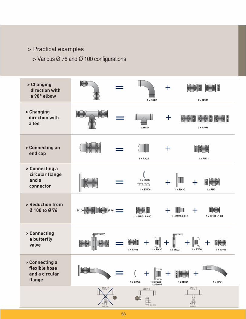
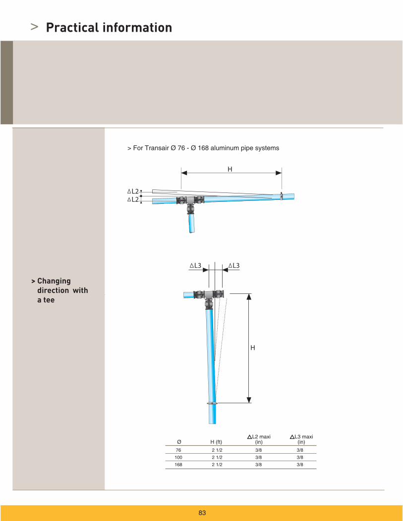
> Changing direction with a 90° elbow
> Changing direction with a tee
> Connecting an end cap
> Connecting a circular flange and a
connector
> Reduction from Ø 100 to Ø 76
> Connecting a butterfly valve
> Connecting a flexible hose and a circular flange
Ø 76 Ø 100
> Transair connectors
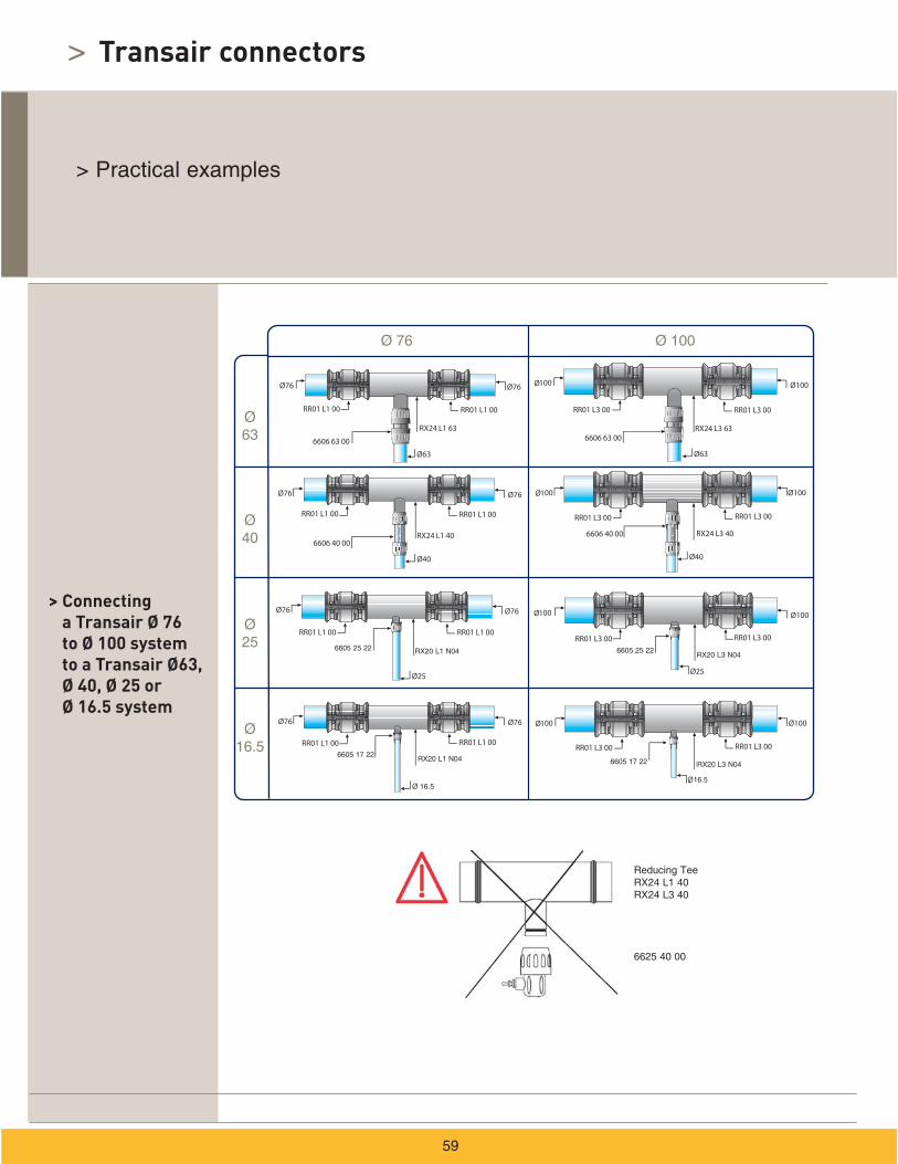
> Connecting a Transair Ø 76 to Ø 100 system to a Transair Ø63, Ø 40, Ø 25 or Ø 16.5 system
> Ø 16.5 Ø 25 Ø 40
> Ø 63
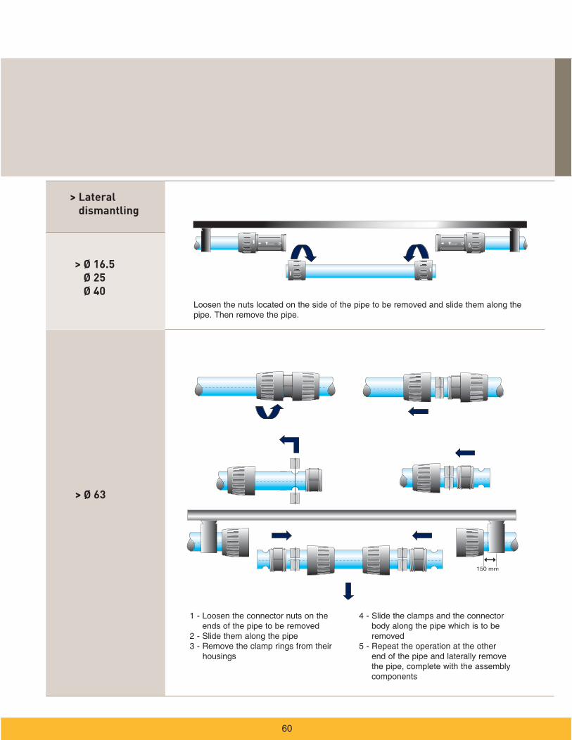
> Lateral dismantling
>
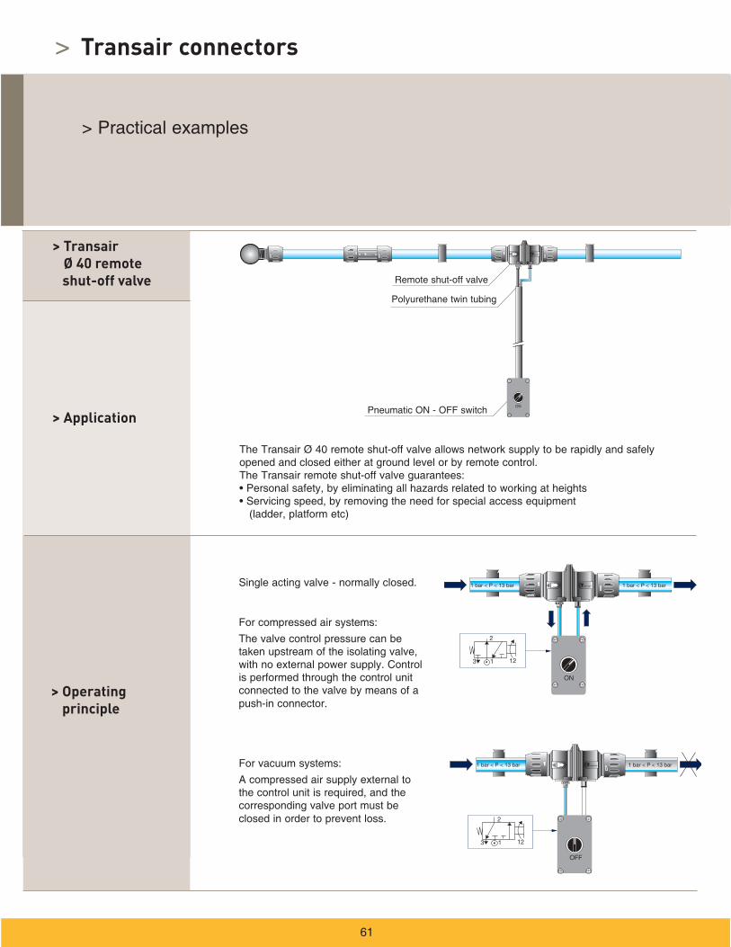
> Application
> Operating principle
> Transair Ø 40 remote
shut-off valve
Transair connectors
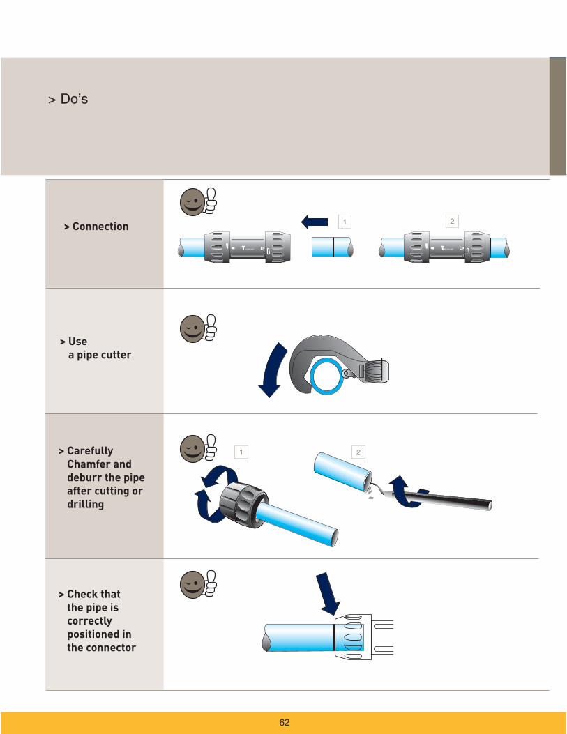
> Connection
> Carefully Chamfer and deburr the pipe after cutting or drilling
> Use a pipe cutter
> Check that the pipe is correctly positioned in the connector
1
1
2
2
>
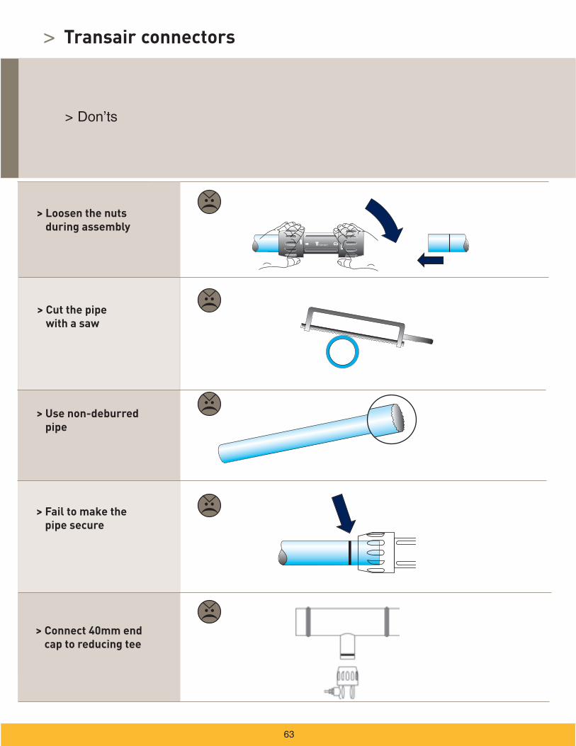
> Loosen the nuts during assembly
> Cut the pipe with a saw
> Use non-deburred pipe
> Fail to make the pipe secure
> Connect 40mm end cap to reducing tee
Transair connectors
>
> Specific instructions for installing a bracket
Transair quick assembly brackets
>
> Tools required
> Procedure
> To Ø 25 or Ø 40
pipe
Transair quick assembly brackets
1
2 3 4
> Tools required
> Procedure
> On Ø 63 pipe
1 2 3 4
>
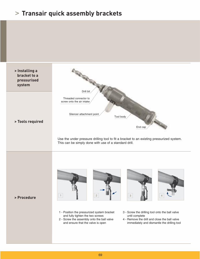
> Installing a bracket
> Tools required
> Procedure
> On Ø 76, Ø 100 or Ø 168 pipe
Drilling tool for aluminum pipe, ref. EW09 00 30 (Ø 76 - Ø 100 ) or EW09 00 64 / EW09 00 51 (Ø 168)
Drill
1 - Drill the aluminum pipe at the desired position using drilling tool ref.
2 - Carefully deburr the pipe
3 - Position bracket ref. RR61 and fully tighten the two screws
4 - Screw on male adapter
Note: Use adapter ref. 6621 25 35 in combination with bracket ref. RR63 to create a Ø 25 take-off point from Ø 76 or Ø 100 pipe.
Deburring tool for aluminum pipe ref. 6698 04 02
Transair quick assembly brackets
1 2
3 4
67
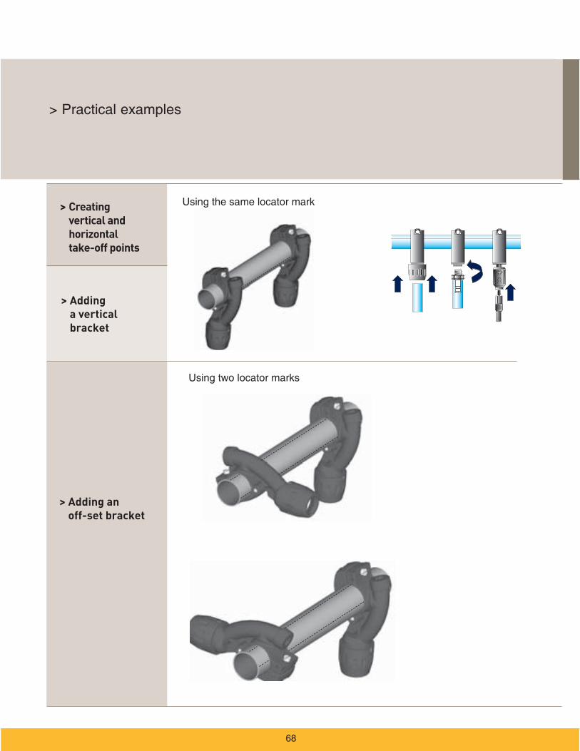
> Adding a vertical bracket
> Adding an off-set bracket
> Creating vertical and horizontal take-off points
1 2
>
> Tools required
> Procedure
> Installing a bracket to a pressurised system
Transair quick assembly brackets
1 2 3 4
6 in min.
R min.
6 in min.
6 in min.
R min.
> Transair flexible hose
> Applications
> Safety
>
4
4
4
3
3
3
12
14
14
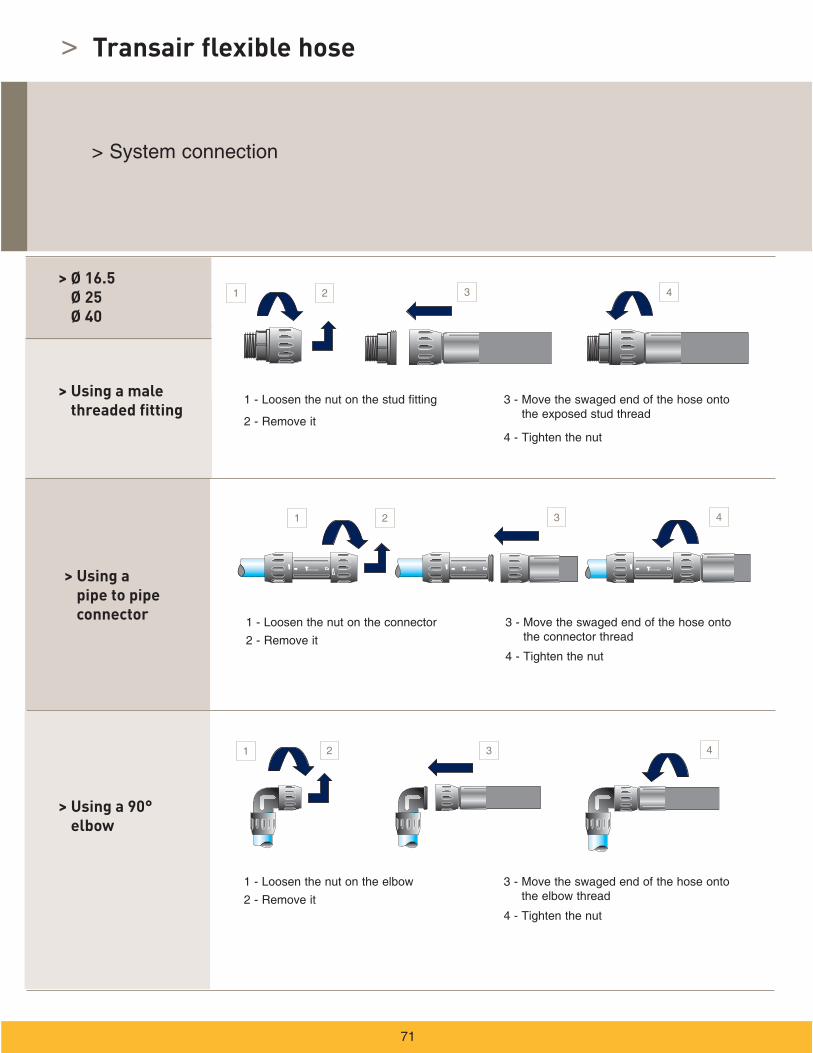
>
> Ø 16.5 Ø 25 Ø 40
> Using a 90° elbow
> Using a male threaded fitting
> Using a pipe to pipe connector
Transair flexible hose
1 3 4
1 2 3 4
1 2 3 4
2
> Using a male threaded
fitting
> Using a pipe to pipe connector
> Using a 90° elbow
> Ø 631 2 3 4
1 2 3 4
1 2 3 4
> Ø 76 Ø 100 Ø 168
> Using a steel clamp
1 2
3 4
> Do’s > Don’ts
>
Fixture accessories
> Transair clip for Ø 16.5, Ø 25, Ø 40 and Ø 63 rigid pipe
> Procedure
> Properties
ø
1 2 3
> Spacer
> Transair fixing clips for Ø 76 - Ø 168
systems
> Fixture accessories
> Offset from a wall
> U-channel type mounting bracket
> Directly onto a wall
> Threaded rod adapter
H
C1E
1 2
> Using beam clamps
> On a metal beam
> Practical information
6666
Z
4088 - 4089 - 4099 - 4002Z1 Z2
4230Z Z
6651
Z Z
6602Z
Z
6606 - 6676Z Z
6612Z
Z
6604Z1
Z2
RA69
Z
6662
RX04Z2
Z1 Z1
RX24+
6606
Z1 Z1
Z2
RX02
Z
Z
RX64 + 6606
Z
VR02
Z Z
RX66 / RA66
Z
R min.
6 in min.
1 2
Ø 16.5 Ø 25 Ø 40 Ø 63 Ø 76 Ø 100
>
Practical information
> Example
H H
HH
> Using an elbow
> Using a quick assembly bracket
H
> Direction change
>
> Changing direction with a tee
Practical information
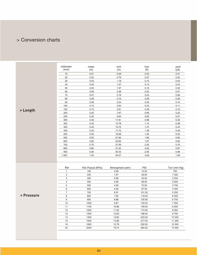
> Length
> Pressure
Bar
>
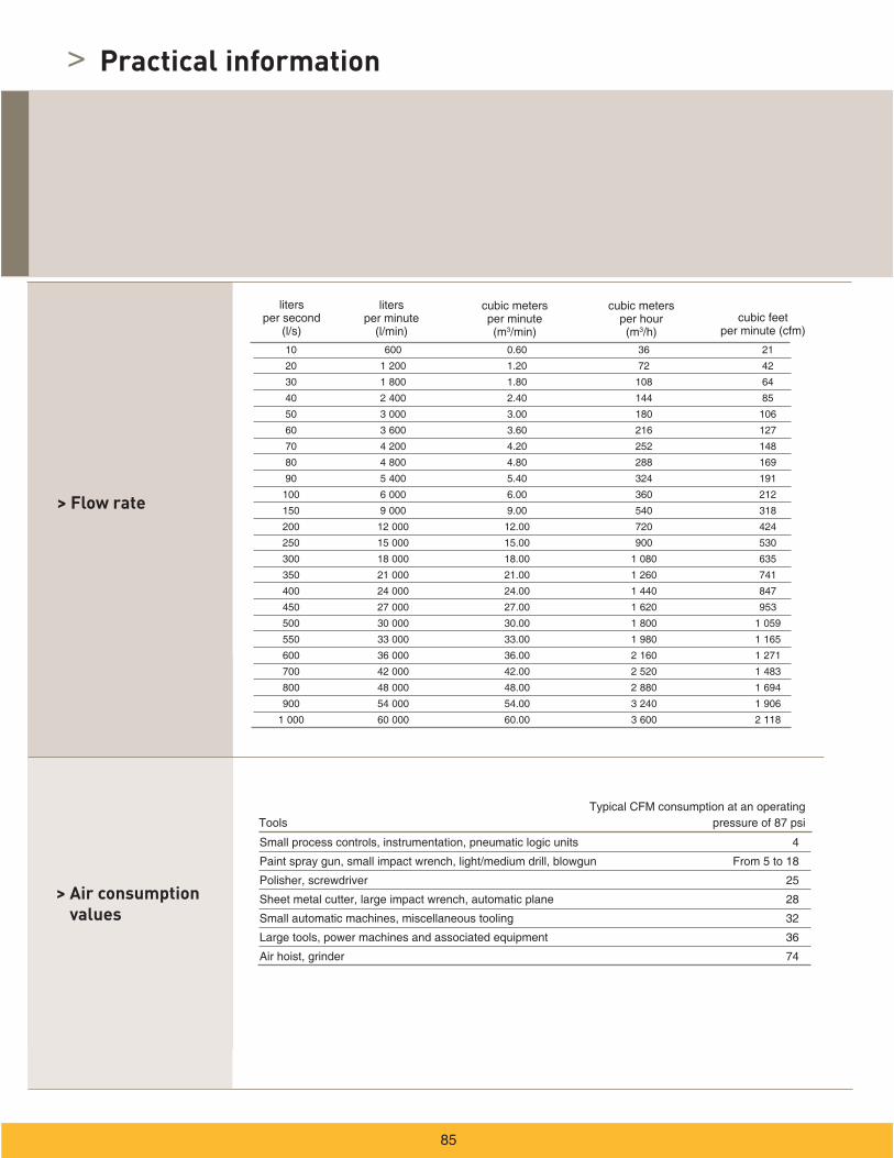
> Flow rate
> Air consumption values
3
3
Practical information
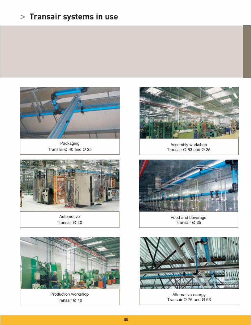
> Transair systems in use
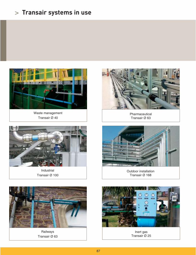
> Transair systems in use
Part numbers index>

AerospaceKey MarketsAftermarket services
Commercial transports
Engines
General & business aviation
Helicopters
Launch vehicles
Military aircraft
Missiles
Power generation
Regional transports
Unmanned aerial vehicles
Key ProductsControl systems & actuation products
Engine systems & components
Fluid conveyance systems& components
Fluid metering, delivery
& atomization devices
Fuel systems & components
Fuel tank inerting systems
Hydraulic systems
& components
Thermal management
Wheels & brakes
AutomationKey Markets Alternative energy
Conveyor & material handling
Factory automation
Food & beverage
Life sciences & medical
Machine tools
Packaging machinery
Paper machinery
Plastics machinery
Primary metals
Safety & security
Semiconductor & electronics
Transportation & automotive
Key Products AC/DC drives & systems
Air preparation
Electric actuators, gantryrobots & slides
Human machine interfaces
Inverters
Manifolds
Miniature fluidics
Pneumatic actuators & grippers
Pneumatic valves & controls
Rotary actuators
Stepper motors, servo motors,
drives & controls
Structural extrusions
Vacuum generators, cups & sensors
Fluid ConnectorsKey Markets
Aerial lift
Agriculture
Bulk chemical handling
Construction machinery
Food & beverage
Fuel & gas delivery
Industrial machinery
Life sciences
Marine
Mining
Mobile
Oil & gas
Renewable energy
Transportation
Key Products Check valves
Connectors for low pressure fluid conveyance
Deep sea umbilicals
Diagnostic equipment
Hose couplings
Industrial hose
Mooring systems & power cables
PTFE hose & tubing
Quick couplings
Rubber & thermoplastic hose
Tube fittings & adapters
Tubing & plastic fittings
HydraulicsKey Markets Aerial lift
Agriculture
Alternative energy
Construction machinery
Forestry
Industrial machinery
Machine tools
Marine
Material handling
Mining
Oil & gas
Power generation
Refuse vehicles
Renewable energy
Truck hydraulics
Turf equipment
Key Products Accumulators
Cartridge valves
Electrohydraulic actuators
Human machine interfaces
Hybrid drives
Hydraulic cylinders
Hydraulic motors & pumps
Hydraulic systems
Hydraulic valves & controls
Hydrostatic steering
Integrated hydraulic circuits
Power take-offs
Power units
Rotary actuators
Sensors
InstrumentationKey Markets Alternative fuels
Biopharmaceuticals
Chemical & refining
Food & beverage
Marine & shipbuilding
Medical & dental
Microelectronics
Nuclear Power
Offshore oil exploration
Oil & gas
Pharmaceuticals
Power generation
Pulp & paper
Steel
Water/wastewater
Key ProductsAnalytical Instruments
Analytical sample conditioningproducts & systems
Chemical injection fittings& valves
Fluoropolymer chemicaldelivery fittings, valves & pumps
High purity gas delivery fittings, valves, regulators& digital flow controllers
Industrial mass flow meters/controllers
Permanent no-weld tube fittings
Precision industrial regulators& flow controllers
Process control double block & bleeds
Process control fittings, valves, regulators & manifold valves
SealKey Markets Aerospace
Chemical processing
Consumer
Fluid power
General industrial
Information technology
Life sciences
Microelectronics
Military
Oil & gas
Power generation
Renewable energy
Telecommunications
Transportation
Key Products Dynamic seals
Elastomeric o-rings
Electro-medical instrumentdesign & assembly
EMI shielding
Extruded & precision-cut,
fabricated elastomeric seals
High temperature metal seals
Homogeneous & insertedelastomeric shapes
Medical device fabrication & assembly
Metal & plastic retainedcomposite seals
Shielded optical windows
Silicone tubing & extrusions
Thermal management
Vibration dampening
Parker’s Motion & Control Product GroupsAt Parker, we’re guided by a relentless drive to help our customers become more productive and achieve higher levels of profitabil-ity by engineering the best systems for their require-ments. It means looking at customer applications from many angles to find new ways to create value. What-ever the motion and control technology need, Parker has the experience, breadth of product and global reach to consistently deliver. No company knows more about motion and control technol-ogy than Parker. For further info call 1 800 C-Parker(1 800 272 7537).
Climate & Industrial ControlsKey Markets
Agriculture
Air conditioning
Construction Machinery
Food & beverage
Industrial machinery
Life sciences
Oil & gas
Precision cooling
Process
Refrigeration
Transportation
Key Products Accumulators
Advanced actuators
CO2 controls
Electronic controllers
Filter driers
Hand shut-off valves
Heat exchangers
Hose & fittings
Pressure regulating valves
Refrigerant distributors
Safety relief valves
Smart pumps
Solenoid valves
Thermostatic expansion valves
FiltrationKey MarketsAerospace
Food & beverage
Industrial plant & equipment
Life sciences
Marine
Mobile equipment
Oil & gas
Power generation & renewable energy
Process
Transportation
Water Purification
Key Products Analytical gas generators
Compressed air filters & dryers
Engine air, coolant, fuel & oil filtration systems
Fluid condition monitoring systems
Hydraulic & lubrication filters
Hydrogen, nitrogen & zero
air generators
Instrumentation filters
Membrane & fiber filters
Microfiltration
Sterile air filtration
Water desalination & purification filters & systems
>
1. Terms and Conditions. Seller’s willingness to offer Products, or accept an order for Products, to or
from Buyer is expressly conditioned on Buyer’s assent to these Terms and Conditions and to the terms
and conditions found on-line at www.parker.com/saleterms/. Seller objects to any contrary or additional
term or condition of Buyer’s order or any other document issued by Buyer.
2. Price Adjustments; Payments. Prices stated on the reverse side or preceding pages of this document
are valid for 30 days. After 30 days, Seller may change prices to reflect any increase in its costs resulting
from state, federal or local legislation, price increases from its suppliers, or any change in the rate, charge,
or classification of any carrier. The prices stated on the reverse or preceding pages of this document
do not include any sales, use, or other taxes unless so stated specifically. Unless otherwise specified
by Seller, all prices are F.O.B. Seller’s facility, and payment is due 30 days from the date of invoice. After
30 days, Buyer shall pay interest on any unpaid invoices at the rate of 1.5% per month or the maximum
allowable rate under applicable law.
3. Delivery Dates; Title and Risk; Shipment. All delivery dates are approximate and Seller shall not be
responsible for any damages resulting from any delay. Regardless of the manner of shipment, title to any
products and risk of loss or damage shall pass to Buyer upon tender to the carrier at Seller’s facility (i.e.,
when it’s on the truck, it’s yours). Unless otherwise stated, Seller may exercise its judgment in choosing
the carrier and means of delivery. No deferment of shipment at Buyers’ request beyond the respective
dates indicated will be made except on terms that will indemnify, defend and hold Seller harmless against
all loss and additional expense. Buyer shall be responsible for any additional shipping charges incurred by
Seller due to Buyer’s changes in shipping, product specifications or in accordance with Section 13, herein.
4. Warranty. Seller warrants that the Products sold hereunder shall be free from defects in material or
workmanship for a period of ten years from the date of shipment to Buyer. This warranty is made only to
Buyer and does not extend to anyone to whom Products are sold after purchased from Seller. The prices
charged for Seller’s products are based upon the exclusive limited warranty stated above, and upon the
following disclaimer: DISCLAIMER OF WARRANTY: THIS WARRANTY COMPRISES THE SOLE AND
ENTIRE WARRANTY PERTAINING TO PRODUCTS PROVIDED HEREUNDER. SELLER DISCLAIMS ALL
OTHER WARRANTIES, EXPRESS AND IMPLIED, INCLUDING MERCHANTABILITY AND FITNESS FOR
A PARTICULAR PURPOSE.
5. Claims; Commencement of Actions. Buyer shall promptly inspect all Products upon delivery. No claims
for shortages will be allowed unless reported to the Seller within 10 days of delivery. No other claims
against Seller will be allowed unless asserted in writing within 60 days after delivery or, in the case of an
alleged breach of warranty, within 30 days after the date within the warranty period on which the defect
is or should have been discovered by Buyer. Any action based upon breach of this agreement or upon
any other claim arising out of this sale (other than an action by Seller for any amount due to Seller from
Buyer) must be commenced within thirteen months from the date of tender of delivery by Seller or, for a
cause of action based upon an alleged breach of warranty, within thirteen onths from the date within the
warranty period on which the defect is or should have been discovered by Buyer.
6. LIMITATION OF LIABILITY. UPON NOTIFICATION, SELLER WILL, AT ITS OPTION, REPAIR OR
REPLACE A DEFECTIVE PRODUCT, OR REFUND THE PURCHASE PRICE. IN NO EVENT SHALL SELLER
BE LIABLE TO BUYER FOR ANY SPECIAL, INDIRECT, INCIDENTAL OR CONSEQUENTIAL DAMAGES
ARISING OUT OF, OR AS THE RESULT OF, THE SALE, DELIVERY, NON-DELIVERY, SERVICING,
USE OR LOSS OF USE OF THE PRODUCTS OR ANY PART THEREOF, OR FOR ANY CHARGES OR
EXPENSES OF ANY NATURE INCURRED WITHOUT SELLER’S WRITTEN CONSENT, EVEN IF SELLER
HAS BEEN NEGLIGENT, WHETHER IN CONTRACT, TORT OR OTHER LEGAL THEORY. IN NO EVENT
SHALL SELLER’S LIABILITY UNDER ANY CLAIM MADE BY BUYER EXCEED THE PURCHASE PRICE
OF THE PRODUCTS.
7. Contingencies. Seller shall not be liable for any default or delay in performance if caused by
circumstances beyond the reasonable control of Seller.
8. User Responsibility. The user, through its own analysis and testing, is solely responsible for making the
final selection of the system and Product and assuring that all performance, endurance, maintenance,
safety and warning requirements of the application are met. The user must analyze all aspects of the
application and follow applicable industry standards and Product information. If Seller provides Product
or system options, the user is responsible for determining that such data and specifications are suitable
and sufficient for all applications and reasonably foreseeable uses of the Products or systems.
9. Loss to Buyer’s Property. Any designs, tools, patterns, materials, drawings, confidential information
or equipment furnished by Buyer or any other items which become Buyer’s property, may be considered
obsolete and may be destroyed by Seller after two consecutive years have elapsed without Buyer placing
an order for the items which are manufactured using such property. Seller shall not be responsible for any
loss or damage to such property while it is in Seller’s possession or control.
10. Special Tooling. A tooling charge may be imposed for any special tooling, including without limitation,
dies, fixtures, molds and patterns, acquired to manufacture Products. Such special tooling shall be and
remain Seller’s property notwithstanding payment of any charges by Buyer. In no event will Buyer acquire
any interest in apparatus belonging to Seller which is utilized in the manufacture of the Products, even if
such apparatus has been specially converted or adapted for such manufacture and notwithstanding any
charges paid by Buyer. Unless otherwise agreed, Seller shall have the right to alter, discard or otherwise
dispose of any special tooling or other property in its sole discretion at any time.
Offer of Sale>
The items described in this document and other documents and descriptions provided by Parker Hannifin Corporation, its subsidiaries and
its authorized distributors (“Seller”) are hereby offered for sale at prices to be established by Seller. This offer and its acceptance by any
customer (“Buyer”) shall be governed by all of the following Terms and Conditions. Buyer’s order for any item described in its document,
when communicated to Seller verbally, or in writing, shall constitute acceptance of this offer. All goods or work described are the Parker
Transair products provided solely by the Fluid Systems Division of Seller and will be referred to as “Products”.
11. Buyer’s Obligation; Rights of Seller. To secure payment of all sums due or otherwise, Seller shall
retain a security interest in the goods delivered and this agreement shall be deemed a Security Agreement
under the Uniform Commercial Code. Buyer authorizes Seller as its attorney to execute and file on Buyer’s
behalf all documents Seller deems necessary to perfect its security interest. Seller shall have a security
interest in, and lien upon, any property of Buyer in Seller’s possession as security for the payment of any
amounts owed to Seller by Buyer.
12. Improper use and Indemnity. Buyer shall indemnify, defend, and hold Seller harmless from any claim,
liability, damages, lawsuits, and costs (including attorney fees), whether for personal injury, property damage,
patent, trademark or copyright infringement or any other claim, brought by or incurred by Buyer, Buyer’s
employees, or any other person, arising out of: (a) improper selection, improper application or other misuse
of Products purchased by Buyer from Seller; (b) any act or omission, negligent or otherwise, of Buyer; (c)
Seller’s use of patterns, plans, drawings, or specifications furnished by Buyer to manufacture Product; or
(d) Buyer’s failure to comply with these terms and conditions. Seller shall not indemnify Buyer under any
circumstance except as otherwise provided.
13. Cancellations and Changes. Orders shall not be subject to cancellation or change by Buyer for any
reason, except with Seller’s written consent and upon terms that will indemnify, defend and hold Seller
harmless against all direct, incidental and consequential loss or damage. Seller may change product
features, specifications, designs and availability with notice to Buyer.
14. Limitation on Assignment. Buyer may not assign its rights or obligations under this agreement without
the prior written consent of Seller.
15. Entire Agreement. This agreement contains the entire agreement between the Buyer and Seller
and constitutes the final, complete and exclusive expression of the terms of the agreement. All prior
or contemporaneous written or oral agreements or negotiations with respect to the subject matter are
herein merged.
16. Waiver and Severability. Failure to enforce any provision of this agreement will not waive that provision
nor will any such failure prejudice Seller’s right to enforce that provision in the future. Invalidation of any
provision of this agreement by legislation or other rule of law shall not invalidate any other provision herein.
The remaining provisions of this agreement will remain in full force and effect.
17. Termination. This agreement may be terminated by Seller for any reason and at any time by giving
Buyer thirty (30) days written notice of termination. In addition, Seller may by written notice immediately
terminate this agreement for the following: (a) Buyer commits a breach of any provision of this agreement
(b) the appointment of a trustee, receiver or custodian for all or any part of Buyer’s property (c) the filing of
a petition for relief in bankruptcy of the other Party on its own behalf, or by a third party (d) an assignment
for the benefit of creditors, or (e) the dissolution or liquidation of the Buyer.
18. Governing Law. This agreement and the sale and delivery of all Products hereunder shall be deemed
to have taken place in and shall be governed and construed in accordance with the laws of the State of
Ohio, as applicable to contracts executed and wholly performed therein and without regard to conflicts
of laws principles. Buyer irrevocably agrees and consents to the exclusive jurisdiction and venue of the
courts of Cuyahoga County, Ohio with respect to any dispute, controversy or claim arising out of or relating
to this agreement. Disputes between the parties shall not be settled by arbitration unless, after a dispute
has arisen, both parties expressly agree in writing to arbitrate the dispute.
19. Indemnity for Infringement of Intellectual Property Rights. Seller shall have no liability for infringement
of any patents, trademarks, copyrights, trade dress, trade secrets or similar rights except as provided in
this Section. Seller will defend and indemnify Buyer against allegations of infringement of U.S. patents, U.S.
trademarks, copyrights, trade dress and trade secrets (“Intellectual Property Rights”). Seller will defend
at its expense and will pay the cost of any settlement or damages awarded in an action brought against
Buyer based on an allegation that a Product sold pursuant to this Agreement infringes the Intellectual
Property Rights of a third party. Seller’s obligation to defend and indemnify Buyer is contingent on Buyer
notifying Seller within ten (10) days after Buyer becomes aware of such allegations of infringement, and
Seller having sole control over the defense of any allegations or actions including all negotiations for
settlement or compromise. If a Product is subject to a claim that it infringes the Intellectual Property Rights
of a third party, Seller may, at its sole expense and option, procure for Buyer the right to continue using
the Product, replace or modify the Product so as to make it noninfringing, or offer to accept return of the
Product and return the purchase price less a reasonable allowance for depreciation. Notwithstanding
the foregoing, Seller shall have no liability for claims of infringement based on information provided by
Buyer, or directed to Products delivered hereunder for which the designs are specified in whole or part
by Buyer, or infringements resulting from the modification, combination or use in a system of any Product
sold hereunder. The foregoing provisions of this Section shall constitute Seller’s sole and exclusive liability
and Buyer’s sole and exclusive remedy for infringement of Intellectual Property Rights.
20. Taxes. Unless otherwise indicated, all prices and charges are exclusive of excise, sales, use, property,
occupational or like taxes which may be imposed by any taxing authority upon the manufacture, sale or
delivery of Products.
21. Equal Opportunity Clause. For the performance of government contracts and where dollar value
of the Products exceed $10,000, the equal employment opportunity clauses in Executive Order 11246,
VEVRAA, and 41 C.F.R. §§ 60-1.4(a), 60-741.5(a), and 60-250.4, are hereby incorporated.
90
© 2012 Parker Hannifin Corporation. All rights reserved.
Parker Hannifin CorporationFluid System Connectors Division
7205 E. Hampton Ave.Mesa, AZ 85209phone 480 830 7764fax 480 325 3571www.parkertransair.com
CAT.3515-TRN
Your complete source for quality tube fittings, hose & hose fittings, brass & composite fittings, quick-disconnect couplings, valves and assembly tools, locally available from a worldwide network of authorized distributors.
Fittings:
Available in inch and metric sizes covering SAE, BSP, DIN, GAZ, JIS and ISO thread configurations, manufactured from steel, stainless steel, brass, aluminum, nylon and thermoplastic.
Hose, Tubing and Bundles:
Available in a wide variety of sizes and materials including rubber, wire-reinforced, thermoplastic, hybrid and custom compounds.
Worldwide Availability:
Parker operates Fluid Connectors manufacturing locations and sales offices throughout North America, South America, Europe and Asia-Pacific.
For information, call toll free...
1-800-C-PARKER
(1-800-272-7537)
Parker Fluid Connectors GroupNorth American Divisions & Distribution Service Centers
North American Divisions
Energy Products Division
Stafford, TXphone 281 566 4500fax 281 530 5353
Fluid System Connectors
Division
Otsego, MIphone 269 694 9411fax 269 694 4614
Hose Products Division
Wickliffe, OHphone 440 943 5700fax 440 943 3129
Industrial Hose Division
Strongsville, OHphone 440 268 2120fax 440 268 2230
Parflex Division
Ravenna, OHphone 330 296 2871fax 330 296 8433
Quick Coupling Division
Minneapolis, MNphone 763 544 7781fax 763 544 3418
Tube Fittings Division
Columbus, OHphone 614 279 7070fax 614 279 7685
Distribution Service Centers
Buena Park, CA
phone 714 522 8840fax 714 994 1183
Conyers, GA
phone 770 929 0330fax 770 929 0230
Louisville, KY
phone 502 937 1322fax 502 937 4180
Portland, OR
phone 503 283 1020fax 503 283 2201
Toledo, OH
phone 419 878 7000fax 419 878 7001fax 419 878 7420 (FCG Kit Operations)
Canada
Grimsby, ONT
phone 905 945 2274fax 905 945 3945(Contact Grimsby for other Service Center locations.)