tranquility digital (dxm2) troubleshooting guide geothermal heat pumps te/tz/tes/tep 97b0601n01...
TRANSCRIPT

DIGITAL Geothermal Heat Pumps
TE/TZ/TES/TEP
97B0601N01
Rev.: 3/10/15
Tranquility® Digital (DXM2) Troubleshooting Guide
Table of ContentsIntroduction 2Troubleshooting Flow Chart 3-9Flow Chart Reference Symbols and Diagrams 10Contactor Chart 12Verifying Pump Feedback Signal 12Removing Powerhead on Modulating Valve 13-14Checking Compressors 15-16Reversing Valve Touch Test Chart 17Performance Troubleshooting 17-18Functional Troubleshooting 20-22Typical Split Water-to-Air Troubleshooting Form 23Typical Water Source Refrigeration Circuit 24 (Heating Cycle)Unit Operating Conditions 25Basic Refrigeration Summary 26Refrigeration Troubleshooting 27-28Auxiliary Heat Check 29Checking Pump Output 29Compressor Contactor Voltage Check 30Check CCH for 24 Volts 30Verifying Contactor 30Verifying Capacitor 31Checking Pump Power Cord 31Replacing Variable-Speed Pump Power Head 32Verifying Power at Molded Plug 32 for CompressorVerifying Antifreeze 33Second Stage Verification 34Verifying 24V at Reversing Valve 35Checking Reversing Valve at DXM2 35A0-2 Jumper 36Checking for Power at DXM2 36
Verifying DC Voltage on DXM2 Board 37 for Modulating Valve CheckTXV Bulb Test 38Verifying Dipswitch Position 39Replacing High Pressure Water Switch 39Verifying a Thermistor 40-41Turning Breaker on in Panel or Aux Heat Control 42Static Pressure Check 42Locating Tstat Version and DXM2 Version 43UltraCheck EZ™ Motor Diagnostic Tool 43Checking Dipswitches on DXM2 44Magnet Test to Shift Reversing Valve 44Checking Blower Line Voltage 45Modulating Valve Loses Configuration 45Hard Reset of Thermostat 46Units Having LT1 Lockouts In Heating 47Electrical—Power Wiring 48LT2 Sensor Location for Non-TAH Air Handlers 49Air Coil Connection 49Lineset Diameters and Charge Information 49Connection to Non-Communicating thermostat and AXM communicating control in TAH Air Handler 50Connection to Non-Communicating thermostat and non-communicating Air Handler/Furnace 50Definitions of Conditions 51-52DXM2 Board Layout and Dipswitches 53AXM Board Layout and Dipswitches 54DXM2 Controls 55-58Typical Wiring Diagrams 59-61ATC32U02 Thermostat Screens and Set Up 62-68Revision History 72
Tranqui l i ty® D i g i t a l ( D X M 2 ) — Tr o u b l e s h o o t i n g G u i d eR e v. : 1 0 M a r c h , 2 0 1 5
2 G e o t h e r m a l H e a t i n g a n d C o o l i n g
Troubleshooting ClimateMaster Tranquility® Digital Packaged Heat Pumps is quite straightforward.
Most problems relate to water flow. Either there isn’t enough water flow or the entering water temperature is improperly supplied. Most service problems can be addressed without refrigerant gauges. In fact, installing gauges on packaged heat pumps can do more harm than good because packaged heat pumps contain less refrigerant compared to split systems. The first thing to do is always perform a water side check (Heat of Extraction for Heating or Heat of Rejection for Cooling) to determine if the unit is operating properly.
Set up and diagnostics are made easier using the communicating thermostat (ATC32) or the communicating service tool (ACDU02). You must have ATC32 or ACDU02 to properly work on ClimateMaster Tranquility® Digital units that use the DXM2 control board.
Follow the flow chart on the following pages to help diagnose and solve your issue.
Introduction

3
Tranqui l i ty® D i g i t a l ( D X M 2 ) — Tr o u b l e s h o o t i n g G u i d eR e v. : 1 0 M a r c h , 2 0 1 5
w w w. c l i m a t e m a s t e r. c o m
Troubleshooting Flow Chart
Did unitstart?
Check that unit voltage reads:
197-254V
Does thermostat say‘No Communication’?
The unit did start but it locked out
Establish power
Check that the compressor is not in a
thermal overload
Check Fault Codefrom thermostator service tool
No Yes
Verify that Dipswitch 1
on S3 is in ‘On’ position
Is there power to DXM2 24V?
(18-31.5V)
A-W
A-Z
No Fault
See Fault Codes and Possible
Causes
A-F
Check that there are 24 volts at CC on
DXM2 board and a call for heating or cooling
A-K
Check for 24V at contactor
18-31.5 volts
A-MNo
Replace the DXM2 Board
Check and possibly replace wiring
No
No
Yes Yes
Next Page
Yes
Yes
No A-A
If it is still not communicating,
check the thermostat wire (Be sure it is not running parallel
along power wire). Ensure all wiring is landed
properly on both DXM2 and
thermostat.
Replace board if current board still does not function
Disconnect and reconnect the wires from the DXM2. This will reset the thermostat.
Verify that the DXM2’s dipswitches
are set properly.
Is the unit properly
configured? See Section 3.0 on page
56.B-G
Hard reset the
thermostat
B-K
Hook Service Tool up to board. Does Service Tool communicate with board?
Also ensure there are no wire nuts;
solder wires if they need to be
extended.
No

Tranqui l i ty® D i g i t a l ( D X M 2 ) — Tr o u b l e s h o o t i n g G u i d eR e v. : 1 0 M a r c h , 2 0 1 5
4 G e o t h e r m a l H e a t i n g a n d C o o l i n g
See Section 3.2 on page 56.
Troubleshooting Flow Chart
My unit has a Modulating
Valve. Is valve opening?
Is the valve having trouble shutting
completely and/or is the unit
locking out?
No
Continued
YesCheck
What are the ∆T set points? Control defaults are 7°
heating and 10° cooling. Open loop units with EWT
less than 50° will need to lower ∆T to 4-5° in the
heating mode.
Valve opens or closes correctly
Yes
Verify A0-2 jumper is in
10V position.
A-V
Be sure unit is configured
for Modulating Valve.
VerifyValve and
powerhead alignment
Manually open the valve 100%. Remove powerhead from valve with powerhead
still energized. Then verify that the notches on valve body are
in the correct position.
Third notch aimed down in unit position.
Then reattach powerhead.
A-C
Next Page
Replace pump power head
No
Is there voltage to the pump?(197-254V)
A-O
The unit startsbut the pump
does not
Check that the A0-2 jumper on
DXM2 board is in PWM position
Yes
A-V
Yes
Replace wire harness
Yes
Yes
No
No
A-P
Check DC Voltage at DXM2 Board
A0-2-Ground = .5-10 VDCIs voltage in this range?
Does the low voltage wiring have a broken
wire?
Check DC Voltage at DXM2 Board
T1-Ground = 3-4 VDC (Pump off) 0-2 VDC (Pump on)
Is voltage in this range?
No
Replace DXM2 board
A-J
Yes
No
Yes
Verify how the units are configured in the thermostat (refer to ‘Section 3.3 - Unit Configuration’ on page 53).
Be sure unit is configured for ‘Variable Speed Pump Single’ if unit is on it’s own loop. If unit shares a loop with other units,
then ensure that the unit is configured for ‘Variable Speed
Pump Parallel.’
B-L
Pump may be locked. Pull pump motor. Can you free
impeller?
Replace pump motor

5
Tranqui l i ty® D i g i t a l ( D X M 2 ) — Tr o u b l e s h o o t i n g G u i d eR e v. : 1 0 M a r c h , 2 0 1 5
w w w. c l i m a t e m a s t e r. c o m
NoYes
Replace wire harness
No
Continued
Troubleshooting Flow Chart
Verify in configuration that the unit is configured
correctly for ECM
YesCheck continuity on
communicating harness from DXM2 to Module. Is there a broken wire?
No
Is 197-254V at the blower motor?
Check the wire harness and
replace if needed
Replace defective part
Next Page
Does blower turn on?
Verify that the wiring on the valve and DXM2 Board are correct. See wiring
diagrams on pages 53-54.
Valve does function but
when the unit shuts off, the valve remains
open.
Verify that the DC voltage on DXM2 between A0-2 and GND. Voltage should
be between 3.3-10VDC. This is the output from the board to the valve.
Verify 3/4” Valve Dipswitch or 1” Valve Dial
A-X
A-C
YesB-I
The unit uses a modulating valve but the thermostat continues to show a variable-
speed pump.
Connect a piece of thermostat wire between T1 and GND on DXM2 so the
DXM2 board sees no feedback.
B-J
No
No
Check DC voltage on DXM2 on packaged or AXM on split with
communicating harness to blower connected 12V–GND should read 9–15V
Does the motor try to spin when giving a ‘G’ call?
Use Emerson EZ Tool to troubleshoot motor and verify motor or module
B-F
B-M

Tranqui l i ty® D i g i t a l ( D X M 2 ) — Tr o u b l e s h o o t i n g G u i d eR e v. : 1 0 M a r c h , 2 0 1 5
6 G e o t h e r m a l H e a t i n g a n d C o o l i n g
Replace defective
wiring
No
Verify that Dipswitch 1:4
is on
NoCall for cooling
Unit starts but does not shift
to cooling
Continued
Verify that you have cooling call at
thermostat
No
YesCheck
reversing valve connection at DXM2. Do you have 24 VAC?
Yes
A-U
Verify 24V at
reversing valve
Yes Replace solenoid on
reversing valve
Yes
In order to increase pressure and move a reversing valve that is sticking, place unit in heating mode and then
remove blower door. Just after removing door, energize the
valve. If it still doesn’t shift, try a strong magnet to pull over
internal slide while energizing.
A-T
B-H Verify RV operation
Replace the reversing valve if it still does not shift
Next Page
If Dipswitch 1:4 is on, replace
board
A-E
Troubleshooting Flow Chart
There are no faults,
but does the compressor
start?
Verify comp contactor.
Verify capacitor. Turn off power and allow 5 minutes for discharge. Then verify
with volt meter the UF reading compare to UF reading on capacitor. Is
capacitor good?
NoA-N
Replace capacitor.
No
YesVerify voltage to compressor at molded plug
Replace molded plug and wire
harness
A-Q
Turn power off and remove molded plug on compressor. Measure
resistance between C-S and C-R.
Replace compressor
A-D
Yes
A-A
Yes
No
Yes
YesIs the blower loud?
Check your model’s airflow configuration.
See Section 3.1 on page 56.
Check static pressure
B-DNo
Verify that all grilles
and registers are open.

7
Tranqui l i ty® D i g i t a l ( D X M 2 ) — Tr o u b l e s h o o t i n g G u i d eR e v. : 1 0 M a r c h , 2 0 1 5
w w w. c l i m a t e m a s t e r. c o m
Verify whether the thermostat is configured
for multi-stage operation
No
Unit does not seem to be in second stage. This is
indicated by the performance check being about 30%
(low).
Verify that you have second
stage call
Does DXM2
CCH have 24V?
Verify that Dipswitch 1:4 is on
NoA-L
Yes Yes YesDoes the rectifier plug on the side
of the compressor have 15-27 VDC?
Replace the rectifier plug
No
With unit running in second stage, check amp draw of comp. Next, remove
rectifier plug. Amps should be lower after removing plug. Reattach plug and verify that amps return to previous higher reading.
Yes
A-S
Replace compressor
No
Continued
The unit started but runs and
loop temp continue to drop
in the heating mode
Yes
Verify the antifreeze level where applicable. Remember that EWT
below 45° needs 15° or lower freeze protection. Verify with appropriate
hydrometer.
A-R
Yes
Antifreeze has been verified as having 15° or lower freeze
protection. Then cut the JW3 jumper
Yes
Is there enough loop in the ground? Is the loop making good contact?
(Example: Is your vertical loop grouted from top to bottom?)
Is the loop turbulent? Min 2500 Reynolds
Number.
Yes
Next Page
Use Pressure Drop Software to verify
If Dipswitch 1:4 is on, replace
board
Troubleshooting Flow Chart
No
No

Tranqui l i ty® D i g i t a l ( D X M 2 ) — Tr o u b l e s h o o t i n g G u i d eR e v. : 1 0 M a r c h , 2 0 1 5
8 G e o t h e r m a l H e a t i n g a n d C o o l i n g
Continued
Configure
No
See Lockout Faults on page 51 under ‘Fault
Codes’
Is there more than one unit
sharing a common loop?
No
Properly configure unit. See Section 3.3 and Section 3.4 on
page 57.
Does this unit have a Variable
Speed Pump and is it configured for parallel pumping?
No
Yes Yes Yes
Is the thermostat configured for the proper
model of the unit? (Example: TZ036) This is found on thermostat’s unit
configuration menu.
Yes YesDoes the unit have the
correct ECM Motor? Check the ECM table, which is in the unit’s IOM.Compare to
the motor in the unit.
Verify pump is supplying enough flow using Pressure Drop
Software. Closed loop 2.25 - 3.0 gpm per ton.
Replace with correct motor
No
The unit periodically
locks out on LT1 in heating or
high pressure in cooling
ATC Thermostat says ‘ECM
Configuration Error’
The unit does run but ATC Thermostat
says ‘Service Needed’
Yes
Troubleshooting Flow Chart
This is the Unit Performance Sentinel. In cooling mode if LT2 is 40° or lower or LT1 is 125° or greater. In heating mode if
LT2 is 125° or greater.
Go to Faults Code 8.
A-F
Next Page
No
No
No

9
Tranqui l i ty® D i g i t a l ( D X M 2 ) — Tr o u b l e s h o o t i n g G u i d eR e v. : 1 0 M a r c h , 2 0 1 5
w w w. c l i m a t e m a s t e r. c o m
Replace DXM2 or AXM
No
Unit runs but does not satisfy
Yes YesThe unit is running. However, there is a load issue. The home is losing or gaining more than the capacity of the
heat pump.
If water flow and airflow are good, then verify refrigerant charge.
Calculate superheat and subcooling.A-H
Troubleshooting Flow Chart
Continued
The unit runs but auxiliary heat is not
working
YesIs the thermostat
calling for auxiliary heat or
emergency heat?
Verify that configuration is set to auxiliary heat in thermostat. See section 2.2.2 on
page 55.
No
Does unit have 197-254V at auxiliary heat
strip?
Turn breaker on in panel or
in auxiliary heat control
B-C
No
Yes Yes
Replace wire harness
No
Does the heat strip control
board have the same 24 VDC as
the DXM2?
Yes
Replace heat strap board
Yes
Verify the Water Side Performance
HE = Heat Extraction in BTUs (Heating) HR = Heat Rejection in BTUs (Cooling)
Calculate using the formula found on A-G.
Check with performance data. Is unit within 10%?
A-G
Verify load using a manual J program.
You may also need to perform a blower door test for true infiltration and thermal imaging for locating heat loss. Also consider a duct
blast to verify that air is being delivered
properly.
Yes
Adjust charge if needed to proper superheat and subcooling ranges.
No
No
Then check for proper TXV operation before adding or removing charge.
A-Y
Does DXM2 or AXM (splits) have 24 VDC at EH1
and/or EH2?
A-I

Tranqui l i ty® D i g i t a l ( D X M 2 ) — Tr o u b l e s h o o t i n g G u i d eR e v. : 1 0 M a r c h , 2 0 1 5
10 G e o t h e r m a l H e a t i n g a n d C o o l i n g
Notes: Specific to Splits
1. When using TES/TEP with communicating Air Handlers (and not using ATC32U02 Thermostat using a 24 volt stat) you must mount stat at Air Handler or unit. For proper communicating between TES/TEP, an Air Handler, ATC32U02 should be placed in the OFF position when not using it as a service tool.
2. When configuring TES or TEP after a board change be sure of correct blower type. Select NONE on tool or thermostat because there is no blower directly connected to the DXM2.
3. TAH Air Handlers can be changed to operate blower on 115 volts instead of 230 volts. Be sure NOT to connect the supplied jumper to other opp. molex plug unless you truly want 115 volts.
4. When installing LT2 Sensor on cased coil or other manu-facturer Air Handler, be sure it is installed between TXV and distributor tubes. If you can not install the sensor in that location then do not in-stall the sensor any where else on the coil and leave jumper on DXM2 board.
5. Ensure that TXV bulb is strapped outside of the Air Handler or Cased Coil on the suction line and that the TXV bulb is insulated.
6. All TES/TEP units come factory charged for an additional 25 feet of lineset. Be sure to add or subtract from this based on your lineset length. Final verifica-tion is looking at superheat and subcooling numbers against operating parameters in IOM.
7. On AXM in TAH Air Handler, the only dipswitch used is #2, which can be used for dehumidification. On the AXM, “ON” is Normal and “OFF” is Dehumidification.
8. When brazing a lineset, use Nitrogen flow to prevent oxidation and carbon build up, because these things can restrict the TXVs. Also, protect service valves with a wet rag or heat block to prevent overheating and causing damage. Always install a biflow filter drier in lineset.
9. For reference connecting low voltage wiring when using other Air Handlers or gas furnace in duel fuel applications, see B-S.
B-R
B-N
B-O
B-P
B-Q
B-S

11
Tranqui l i ty® D i g i t a l ( D X M 2 ) — Tr o u b l e s h o o t i n g G u i d eR e v. : 1 0 M a r c h , 2 0 1 5
w w w. c l i m a t e m a s t e r. c o m
Reference Symbols and Diagramsfor Flow Chart

Tranqui l i ty® D i g i t a l ( D X M 2 ) — Tr o u b l e s h o o t i n g G u i d eR e v. : 1 0 M a r c h , 2 0 1 5
12 G e o t h e r m a l H e a t i n g a n d C o o l i n g
Verifying Pump Feedback SignalA-B
Contactor ChartA-A
Contactor Chart
Contactorclosed
Motor doesnot hum
Burnedcontacts
Open in lowvoltage circuit
Incorrectwiring
Open motorwiring
Open overload switch
Motor hums, cuts off on overload circuitbreaker or blows
fuses
Compressor tight or stuck
High discharge pressure not
equalized
Low linevoltage
Burnt out oropen winding
Non-condensibles in refrigerant circuit
Contactor open
Buzzing
Checkcontactor
Normal voltageto coil
Contactor defective, jammed or hung up
Low voltageto coil
Wrong gauge ofthermostat wire
Low voltage from transformer
Not buzzing
Loosewire
No voltageto coil
No powerto control circuit
Voltageto coil
Coil opencircuited
P1
Alarm
Relay
Comp
Relay
OY1 Y2 W G CR AL1
24Vd
c
EH1
EH2
P6
RC
Off
O
n
JW3
A
OVR
ESDCR N
SBAL2
JW1
Acc1
Relay
Acc2
Relay
H
CO
MN
C1
NO
1
CO
MN
C2
NO
2
P3C
ORVRVLT1
LT1
LT2
LT2
LP LPHP
HP P7
Stat
usFa
ult
R RC
C
CC
GCO
S1
S2
1 12 1 4
Factory Use
(240
Vac)
Com
N.O
.
Fan
Enab
le
5 1/
2"
7"6
1/2"
5"
Use
4 m
ount
ing
scre
ws
#6 s
heet
met
al s
crew
1” l
ong
1.5
3/8”
sta
ndof
f
Fact
ory
low
volta
ge m
olex
conn
ectio
n fo
run
it ha
rnes
s
Fact
ory
low
volta
ge m
olex
conn
ectio
n fo
rel
ectri
c he
atha
rnes
s
Mic
roU
1 Off
O
n
P2
CO
HC
OM
AO2
P11
Gnd
T1P1
0T2
T2T3
T3T4
T4T5
P9 T5T6
T6
A0-1
A0-2
Off
O
n
S3RV Re
layCC
HRe
lay
Test
P5
B-G
ndP4
A+24
V(2
40Va
c)
Fan
Spee
dN
.O.
N.C
.
12V
OU
TG
ndP8 IN NC
P12
Not
e: T
here
is o
nly
one
T1 c
onne
ctio
n
1 2 3 4
1 2 3 4 5 6 7 8
1 2 3 4 5 6 7 8
AO1
Gnd 0-2 VDC with pump on
3-4 VDC with pump off
Ensure correct wiring on T1=Yellow, A0-2=White. If not, voltage may look good but pump may not operate.

13
Tranqui l i ty® D i g i t a l ( D X M 2 ) — Tr o u b l e s h o o t i n g G u i d eR e v. : 1 0 M a r c h , 2 0 1 5
w w w. c l i m a t e m a s t e r. c o m
On 3/4” valve, be sure that dip switch is moved up or toward center of valve and valve closes.
For Proper Valve-to-Head AlignmentBefore removing power head, go to manual mode and open valve to 100%. Stay on that screen and with the valve powered open, remove power head. Verify or rotate physical valve to the
position.
Open
Closed
Removing Powerhead on ¾-Inch Modulating ValveA-C

Tranqui l i ty® D i g i t a l ( D X M 2 ) — Tr o u b l e s h o o t i n g G u i d eR e v. : 1 0 M a r c h , 2 0 1 5
14 G e o t h e r m a l H e a t i n g a n d C o o l i n g
Removing Powerhead on 1-Inch Modulating ValveA-C
2) The 1-inch valve includes a tool to remove the power head.
See previous page for proper valve-to-head alignment.
Open
Closed
1) Rotate dial to ‘1’ on the 1-Inch valve.

15
Tranqui l i ty® D i g i t a l ( D X M 2 ) — Tr o u b l e s h o o t i n g G u i d eR e v. : 1 0 M a r c h , 2 0 1 5
w w w. c l i m a t e m a s t e r. c o m
Checking CompressorsA-D
Compressor C-S Ohms
C-R Ohms Unit
ZPS20 1.64 1.30 TZ024, TE026 TEP/TES026
ZPS30 1.52 0.88 TZ036, TE038 TEP/TES038
ZPS40 1.86 0.52 TZ048, TE049 TEP/TES049
ZPS51 1.68 0.41 TZ060, TE064 TEP/TES064
ZPS60 1.85 0.34 TE072
ZPS26 1.90 1.02 TZ030
ZPS35 1.55 0.62 TZ042
Note: Readings are good ± 7%
Note: Reading S-R = C-S + C-R Readings Example: ZPS20 S-R = 2.94 Ohms
Compressor Ohms Table
Overload opens
RS
C
SuctionLine
RS
C
RS
C
RS
C
Compressor with Open Internal Overload
If both R and S are open to common, Internal overload is open.
Overload opens
RS
C
SuctionLine
RS
C
RS
C
RS
C
Open run winding (infinite) resistance. Start winding shows measurable resistance.
Overload opens
RS
C
SuctionLine
RS
C
RS
C
RS
C
Note: If not, O resistance will be close to it. C-S and C-R will have high resistance above 3 ohms.
Overload opens
RS
C
SuctionLine
RS
C
RS
C
RS
C
Check for ground by placing one lead on suction line.
Compressor with Open Run Winding
Compressor with Shorted Windings Compressor Winding Shorted to Ground

Tranqui l i ty® D i g i t a l ( D X M 2 ) — Tr o u b l e s h o o t i n g G u i d eR e v. : 1 0 M a r c h , 2 0 1 5
16 G e o t h e r m a l H e a t i n g a n d C o o l i n g
An Alternative Way of Checking CompressorsA-D
Megohm Values of Copeland Compressors
For years servicemen have used megohmeters to evaluate compressor motor windings. However, most megohmeter manufacturers publish guidelines that apply to open motors. For this reason, Emerson Climate Technologies has investigated the use of megohmeters on hermetic and semi-hermetic compressors.
When using megohmeters to evaluate the motor insulation of compressors, it is important to understand that they should not be used as one would a volt-ohm meter. A single megohmeter reading gives little insight into the condition of a motor’s insulation.
Megohmeters are best used as a part of a regular maintenance program to monitor trends (over several months). For example, one might record a megohm value and compare it to a previous reading. If subsequent readings show a trend of lower and lower values, then corrective action (such as system clean up) should be taken.
Emerson does not incorporate the megohmeter into any of its quality checks. All Copeland® compressors must pass U.L. required tests using hi-potential current leakage testers (“hi-pot”). Studies performed by Emerson have found that compressors with megohmeter readings as low as 0.5 megohms still pass the hi-pot.
There are many factors that affect megohm readings including contaminated refrigerant, oil level, refrigerant in oil and current leakage through electrical fusites or terminal plates.
Any external electrical components connected to the compressor terminals also affect megohm readings. Wires, contactors and relays all leak current and will decrease compressor megohmeter readings if not disconnected.
As mentioned earlier a single megohm reading cannot be used to condemn a compressor since many other factors are involved. However, limits can be placed on megohm values that dictate action be taken. Emerson has found that these limits are related to the rated voltage of the compressor. Megohm values equal to or greater than 1000 ohms per volt are probably acceptable. For example, a 460 volt compressor might show a megohm reading of 460,000 ohms or 0.46 megohm. Compressors with rated voltages of 208 to 230 volts would then be operable at megohm values of 0.208 to 0.230 megohms; for simplicity, Emerson has set the limit at 0.5 megohms before a compressor is condemned. Figure 1 shows the required procedure for checking compressors with a megohmeter.
New compressors that have never been installed will not need any system clean-up procedures so long as the megohm reading is above 0.5. A baseline reading must be established for comparison purposes and since this is its fi rst reading this will be its baseline value.
Megohmmeter
2© 2010 Emerson Climate TechnologiesPrinted in the U.S.A.
AE4-1294
Application Engineering
B U L L E T I N
Figure 1 Megohmeter Test Procedure
B1A
8102012450

17
Tranqui l i ty® D i g i t a l ( D X M 2 ) — Tr o u b l e s h o o t i n g G u i d eR e v. : 1 0 M a r c h , 2 0 1 5
w w w. c l i m a t e m a s t e r. c o m
Reversing Valve Touch Test ChartA-E
4
2
3
1
65
Line toAir Coil
Discharge fromCompressor
Line toCoax
Suction Lineto Compressor
VALVE OPERATING CONDITION
NOTES: * Temperature of Valve Body** Warmer than Valve Body
1 2 3 4 5 6
NORMAL OPERATION OF VALVE
NormalCOOLING Hot Cool Cool
23 (2)Hot
23 (7) TVB *TVB
NormalHEATING Hot Cool Hot
23 (1)Cool23 (2) TVB *TVB
MALFUNCTION OF VALVE Possible causes Corrections
Valve will not shift from heat
to cool
Check electrical circuit and coilNo Voltage to coil Repair electrical circuit
Defective coil (No resistance) Replace coil
Check refrigeration chargeLow charge Repair leak, recharge system
Pressure differential too high Recheck system
Hot Cool Hot23 (1)
Cool23 (2) Hot *TVB
Pilot valve okay. Dirt in one bleeder hose. Deenergize solenoid, raise head pressure and reenergize solenoid to break dirt loose. If unsuccessful, remove valve and clean out. Check on air before installing if not movement, reduce valve, add strainer to decharge tube and mount valve horizontally
Platon cup leak Stop unit. After pressure equalizes, restart with solenoid energized. If valve shifts, restart with compressor running. If still no shift, replace valve.
Hot Cool Hot23 (1)
Cool23 (2) Hot *TVB Clogged pipe tubes.
Raise head pressure, operate solenoid to free. If still no shift, replace valve
Hot Cool Hot23 (1)
Cool23 (2) Hot Hot Both parts of pilot open. (Back seat port did not
close)Raise head pressure, operate solenoid to free partially clogged port. If still no shift, replace valve.
Warm Cool Warm23 (1)
Cool23 (2) Warm TVB Defective compressor
Start to shift but does not
complete reversal
Hot Warm Warm Hot *TVB Hot
Not enough pressure differential at start of stroke or not enough flow to maintain pressure differential.
Check unit for correct operating pressures and charge. Raise head pressure. If no shift, use valve with smaller ports.
Body damage. Replace valves.
Hot Warm Warm Hot Hot Hot Both parts of pilot open. Raise head pressure, operate solenoid. If no shift, replace valve.
Hot Hot Hot Hot *TVB Hot
Body damage. Replace valve.
Valve hung up at mid-stroke. Pumping volume of compressor not sufficient to maintain reversal.
Raise head pressure, operate solenoid. If no shift, use valve with smaller ports.
Hot Hot Hot Hot Hot Hot Both parts of pilot open. Raise head pressure. Operate solenoid. If no shift, replace valve.
Apparent lock in cooling
Hot Cool Cool23 (2)
Hot23 (1) **WVB *TVB Pilot needle on end of side leaking. Operate valve several times then recheck. If excessive leak,
replace valve.
Hot Cool Cool23 (2)
Hot23 (1) **WVB **WVB Pilot needle and piston needle leaking Operate valve several times then recheck. If excessive leak,
replace valve.
Will not shift cool to heat
Hot Cool Cool23 (2)
Hot23 (1) TVB TVB
Pressure differential too high Stop unit. Will reverse during equalization period. Recheck system.
Clogged pilot tube Raise head pressure. Operate solenoid to free dirt. If still no shift, replace valve.
Hot Cool Cool23 (2)
Hot23 (1) TVB Hot
Dirt in bleeder hole Raise head pressure. Operate solenoid. Replace valve.
Piston cup leakStop unit. After pressures equalize, restart with solenoid deenergized. If valve shifts, reattempt with compressor running. If it still will not reverse while running, replace valve.
Hot Cool Cool23 (2)
Hot25 (1) Hot Hot Defective pilot. Replace valve.
Warm Cool Cool23 (2)
Warm25 (1) *TVB Warm Defective compressor.

Tranqui l i ty® D i g i t a l ( D X M 2 ) — Tr o u b l e s h o o t i n g G u i d eR e v. : 1 0 M a r c h , 2 0 1 5
18 G e o t h e r m a l H e a t i n g a n d C o o l i n g
Symptom Htg Clg Possible Cause Solution
Insufficient Capacity/Not Cooling or Heating Properly
X X Dirty filter Replace or clean
Rduced or no air flowCheck for dirty air filter and clean or replace
in heating Check fan motor operation and airflow restrictionsToo high of external static - check static vs blower table
Reduced or no air flow Check for dirty air filter and clean or replace
in cooling Check fan motor operation and airflow restrictionsToo high of external static - check static vs blower table. See B-D.
X X Leaky duct workCheck supply and return air temperatures at the unit and atdistant duct registers if significantly different, duct leaksare present. Have a duct blast test performed.
X X Low refrigerant charge Check superheat and subcooling per chartX X Restricted metering device Check superheat and subcooling per chart - replace if
restriction. Both SH and SC will be high.X Defective reversing va lve Perform RV touch test
X X Thermostat improperly located Check location and for air drafts behind statX X Unit undersized Recheck loads & sizing check sensible clg load and heat
pump capacity
X X Scaling in water heat exchanger Perform Scaling check and clean if necessary
X X Inlet water too hot or cold Check load, loop sizing, loop backfill, ground moisture.
High Head Pressure
XReduced or no air flow
Check for dirty air filter and clean or replace
in heatingCheck fan motor operation and airflow restrictionsToo high of external static - check static vs blower table.See B-D.
X Reduced or no water flow Check pump operation or valve operation/settingin cooling Check water flow adjust to proper flow rate
X Inlet water too hot Check load, loop sizing, loop backfill, ground moisture
X Air temperature out of range inheating Bring return air temp within design parameters
X Scaling in water heat exchanger Perform Scaling check and clean if necessaryX X Unit over charged Check superheat and subcooling - reweigh in chargeX X Non-condensables insystem Vacuum system and reweigh in charge. Vacuum to min
500 microns.X X Restricted metering device Check superheat and subcooling per chart - replace
Low Suction Pressure
X Reduced water flow Check pump operation or water valve operation/settingin heating Plugged strainer or filter - clean or replace
Check water flow adjust to proper flow rate. Pump or value ∆T.
X Water temperature out of range Bring water temp within design parameters
X Reduced air flow Check for dirty air filter and clean or replace
in cooling Check fan motor operation and airflow restrictionsToo high of external static - check static vs blower table
X Air temperature out of range Too much cold vent air - bring entering air temp withindesign parameters
X X Insufficient charge Check for refrigerant leaks
Low Dischage Air Temperature in Heating
X Too high of air flow Check fan motor speed selection and airflow chart
X Poor performance See “Insufficient Capacity”
High Humidity
X Too high of air flow Check fan motor speed selection and airflow chart.Return air temp may be too low.
X Unit oversized Recheck loads and sizing check sensible clg load and heat pump capacity
Only Compressor Runs
X X Thermostat wiring Check G wiring at heat pump. Jumper G and R for fanoperation.
X X Fan motor relayJumper G and R for fan operation. Check for Line voltageacross blower relay contacts.Check fan power enable relay operation (if present)
X X Fan motor Check for line voltage at motor. Check capacitor
X X Thermostat wiringCheck thermostat wiring at or DXM2. Put in Test Mode and then jumper Y1 and W1 to R to give call for fan,compressor and electric heat.
Unit Doesn't Operate in Cooling
X Reversing Valve
Set for cooling demand and check 24VAC on RV coil.If RV is stuck, run high pressure up by reducing water flowand while operating engage and disengage RV coil voltageto push valve.
X Thermostat setup
X Thermostat wiringCheck O wiring at heat pump. DXM2 requires call for compressor to get RV coil “Click.”
X
X
Modulating Valve Troubleshooting
X
Improper output setting Verify the AO-2 jumper is in the 0-10V position
No valve operation Check voltage to the valve
X No valve output signal Check DC voltage between AO2 and GND. Should be 0when valve is off and between 3.3v and 10v when valveis on.
Replace valve if voltage and control signals are present at the valve and it does not operate
For DXM2 check for “O” RV setup not “B” if uses conv stat.
Performance TroubleshootingA-F

19
Tranqui l i ty® D i g i t a l ( D X M 2 ) — Tr o u b l e s h o o t i n g G u i d eR e v. : 1 0 M a r c h , 2 0 1 5
w w w. c l i m a t e m a s t e r. c o m
Performance TroubleshootingA-F
Symptom Htg Clg Possible Cause Solution
Insufficient Capacity/Not Cooling or Heating Properly
X X Dirty filter Replace or clean
Rduced or no air flowCheck for dirty air filter and clean or replace
in heating Check fan motor operation and airflow restrictionsToo high of external static - check static vs blower table
Reduced or no air flow Check for dirty air filter and clean or replace
in cooling Check fan motor operation and airflow restrictionsToo high of external static - check static vs blower table. See B-D.
X X Leaky duct workCheck supply and return air temperatures at the unit and atdistant duct registers if significantly different, duct leaksare present. Have a duct blast test performed.
X X Low refrigerant charge Check superheat and subcooling per chartX X Restricted metering device Check superheat and subcooling per chart - replace if
restriction. Both SH and SC will be high.X Defective reversing va lve Perform RV touch test
X X Thermostat improperly located Check location and for air drafts behind statX X Unit undersized Recheck loads & sizing check sensible clg load and heat
pump capacity
X X Scaling in water heat exchanger Perform Scaling check and clean if necessary
X X Inlet water too hot or cold Check load, loop sizing, loop backfill, ground moisture.
High Head Pressure
XReduced or no air flow
Check for dirty air filter and clean or replace
in heatingCheck fan motor operation and airflow restrictionsToo high of external static - check static vs blower table.See B-D.
X Reduced or no water flow Check pump operation or valve operation/settingin cooling Check water flow adjust to proper flow rate
X Inlet water too hot Check load, loop sizing, loop backfill, ground moisture
X Air temperature out of range inheating Bring return air temp within design parameters
X Scaling in water heat exchanger Perform Scaling check and clean if necessaryX X Unit over charged Check superheat and subcooling - reweigh in chargeX X Non-condensables insystem Vacuum system and reweigh in charge. Vacuum to min
500 microns.X X Restricted metering device Check superheat and subcooling per chart - replace
Low Suction Pressure
X Reduced water flow Check pump operation or water valve operation/settingin heating Plugged strainer or filter - clean or replace
Check water flow adjust to proper flow rate. Pump or value ∆T.
X Water temperature out of range Bring water temp within design parameters
X Reduced air flow Check for dirty air filter and clean or replace
in cooling Check fan motor operation and airflow restrictionsToo high of external static - check static vs blower table
X Air temperature out of range Too much cold vent air - bring entering air temp withindesign parameters
X X Insufficient charge Check for refrigerant leaks
Low Dischage Air Temperature in Heating
X Too high of air flow Check fan motor speed selection and airflow chart
X Poor performance See “Insufficient Capacity”
High Humidity
X Too high of air flow Check fan motor speed selection and airflow chart.Return air temp may be too low.
X Unit oversized Recheck loads and sizing check sensible clg load and heat pump capacity
Only Compressor Runs
X X Thermostat wiring Check G wiring at heat pump. Jumper G and R for fanoperation.
X X Fan motor relayJumper G and R for fan operation. Check for Line voltageacross blower relay contacts.Check fan power enable relay operation (if present)
X X Fan motor Check for line voltage at motor. Check capacitor
X X Thermostat wiringCheck thermostat wiring at or DXM2. Put in Test Mode and then jumper Y1 and W1 to R to give call for fan,compressor and electric heat.
Unit Doesn't Operate in Cooling
X Reversing Valve
Set for cooling demand and check 24VAC on RV coil.If RV is stuck, run high pressure up by reducing water flowand while operating engage and disengage RV coil voltageto push valve.
X Thermostat setup
X Thermostat wiringCheck O wiring at heat pump. DXM2 requires call for compressor to get RV coil “Click.”
X
X
Modulating Valve Troubleshooting
X
Improper output setting Verify the AO-2 jumper is in the 0-10V position
No valve operation Check voltage to the valve
X No valve output signal Check DC voltage between AO2 and GND. Should be 0when valve is off and between 3.3v and 10v when valveis on.
Replace valve if voltage and control signals are present at the valve and it does not operate
For DXM2 check for “O” RV setup not “B” if uses conv stat.

Tranqui l i ty® D i g i t a l ( D X M 2 ) — Tr o u b l e s h o o t i n g G u i d eR e v. : 1 0 M a r c h , 2 0 1 5
20 G e o t h e r m a l H e a t i n g a n d C o o l i n g
Fault Htg Clg Possible Cause Solution
Main Power Problems X X Green status LED off
Check Line Voltage circuit breaker and disconnect between 197-254 voltsCheck for line voltage between L1 and L2 on the contactorCheck for 24VAC between R and C on DXM 18-31.5Check primary/secondary voltage on transformer
HP Fault Code 2
X Reduced or no water flow Check pump operation or valve operation/settingin cooling Check water flow adjust to proper flow rate
X Water t emperature out of range incooling
Bring water temp within design parameters. Water is too warm.
X Reduced or no air flowCheck for dirty air filter and clean or replace
in heatingCheck fan motor operation and airflow restrictionsDirty air coil- construction dust etc.Too high of external static. Check static vs blower table
X Air t emperature out of range inheating Bring return air temp within design parameters
X X Overcharged with refrigerant Check superheat/subcooling vs typical operating conditiontable
X X Bad HP switch Check switch continuity and operation - Replace
LP/LOC Fault-Code 3 X X Insufficient charge Check for refrigerant leaksLow Pressure/Loss of Charge X Compressor pump down at start-
up Check charge and start-up water flow
LT1 Fault - Code 4
X Reduced or no water flowCheck pump operation or water valve operation/setting
Water Low Temperature
in heatingPlugged strainer or filter - clean or replaceCheck water flow adjust to proper flow rate
X Inadequate anti-freeze level Check antifreeze specific gravity with hydrometer. See A-R.
X Improper low temperature setting(30°F vs 10°F)
Clip JW3 (LT1) jumper for antifreeze use. Be sure loop has 15º freeze protection
X Water t emperature out of range Bring water temp within design parametersX X Bad thermistor Check temp and impedance correlation per chart
LT2 Fault - Code 5Low Air Temperature
X Reduced or no air flowCheck for dirty air filter and clean or replace
in coolingCheck fan motor operation and airflow restrictionsToo high of external static - check static vs blower table
X Air temperature out of range Too much cold vent air. Bring entering air temp within design parameters that IOM specifies.
X Improper low temperature setting(30°F vs 10°F)
Normal airside applications will require. Only setting forpackaged units is 30º.
X X Bad thermistor Check temp and impedance correlation per chart
Condensate Fault - Code 6 High Condensate Level
X X Blocked drain Check for blockage and clean drainX X Improper trap Check trap dimensions and location ahead of vent
X Poor drainageCheck for piping slope away from unitCheck slope of unit toward outletPoor venting - check vent location
X Moisture on sensor Check for moisture shorting to air coil
Over/Under Voltage - Code 7
X X Under voltage
Check power supply and 24VAC voltage before and duringoperation
(Auto Resetting)
Check power supply wire sizeCheck compressor starting. Need hard start kit?Check 24VAC and unit transformer tap for correct powersupply voltage. See A-W.
X X Over voltageCheck power supply voltage and 24VAC before and duringoperation.Check 24VAC and unit transformer tap for correct powersupply voltage
Unit PerformanceSentinel-Code 8
X Heating Mode LT2>125°F Check for poor air flow or overcharged unit
X Cooling Mode LT1>125°F ORLT2< 40°F Check for poor water flow, or air flow
No Fault Code ShownX X No compressor operation See 'Only Fan Operates'X X Compressor overload Check and replace if necessaryX X Control board Reset power and check operation
Unit Short Cycles
Check Thermostat Location and Anticipation Setting
X X Dirty air filter Check and clean air filte rX X Unit in 'Test Mode' Reset power or wait 20 minutes for auto exit
X X Unit selection Unit may be oversized for space - check sizing for actualload of space
X X Compressor overload Check and replace if necessary
Only Fan Runs
X X Thermostat position Insure thermostat set for heating or cooling operationX X Unit locked out Check for lockout codes - reset powerX X Compressor overload Check compressor overload - replace if necessary
X X Thermostat wiringCheck thermostat wiring at DXM2 - put in Test Mode and
Swapped ThermistorCode 9 X X LT1 and LT2 swapped Reverse position of thermistors
ESD - ERV Fault (DXM Only) Green Status LED Code 3
X X ERV unit has fault(Rooftop units only) Troubleshoot ERV unit fault
jumper Y1 and R to give call for compressor
X X Plugged air filter
X X Restricted return air flow
Replace air filterFind and eliminate rectriction - increase return duct and/or grille size. Check static pressure. See the diagram on B-D.
ECM Fault - Code 10
X X Blower does not operate Check blower line voltage. See B-I.Check blower low voltage wiring
Blower operating with incorrectairflow
Wrong unit size selection
Wrong unit family selection
Wrong motor sizeIncorrect blower selection
Low Air Coil Pressure Fault(ClimaDry) Code 11
X Reduced or no air flow in coolingor ClimaDry
Low Air Coil Temperature Fault - (ClimaDry) Code 12
X Reduced airflow in cooling, ClimaDry, or constant fan
Air temperature out of range
Check switch continuity and operation - replaceBad pressure switch
Air temperature out of range
Bad thermistor Check temp and impedance correlation per chart
IFC Fault Code 13Internal Flow Controller Fault
XX No pump output signal Check DC voltage between A02 and GND - should be between 0.5 and 10 VDC with pump active. See A-J.
Low pump voltage Check line voltage to the pump. See picture A-O.
No pump feedback signal Check DC voltage between T1 and GND. Voltage should be between 3 and 4 VDC with pump OFF, and between 0 and 2 VDC with the pump ON. See A-B.
Bad pump RPM sensor Replace pump if the line voltage and control signals are present at the pump, and the pump does not operate
Fault Htg Clg Possible Cause Solution
Check for dirty air filter and clean or replaceCheck fan motor operation and airflow restrictionsToo high of external static - check static vs blower tableToo much cold vent air - bring entering air temp withindesign parameters
Check for dirty air filter and clean or replaceCheck fan motor operation and airflow restrictionsToo high of external static - check static vs blower tableToo much cold vent air - bring entering air temp withindesign parameters
High Pressure
X Frozen water heat exchanger Thaw heat exchanger (water pressure switches).X X Bad HPWS Switch Replace HPWS Switch. See B-A.
Com
mer
cial
Onl
yFunctional Troubleshooting
A-F

21
Tranqui l i ty® D i g i t a l ( D X M 2 ) — Tr o u b l e s h o o t i n g G u i d eR e v. : 1 0 M a r c h , 2 0 1 5
w w w. c l i m a t e m a s t e r. c o m
Fault Htg Clg Possible Cause Solution
Main Power Problems X X Green status LED off
Check Line Voltage circuit breaker and disconnect between 197-254 voltsCheck for line voltage between L1 and L2 on the contactorCheck for 24VAC between R and C on DXM 18-31.5Check primary/secondary voltage on transformer
HP Fault Code 2
X Reduced or no water flow Check pump operation or valve operation/settingin cooling Check water flow adjust to proper flow rate
X Water t emperature out of range incooling
Bring water temp within design parameters. Water is too warm.
X Reduced or no air flowCheck for dirty air filter and clean or replace
in heatingCheck fan motor operation and airflow restrictionsDirty air coil- construction dust etc.Too high of external static. Check static vs blower table
X Air t emperature out of range inheating Bring return air temp within design parameters
X X Overcharged with refrigerant Check superheat/subcooling vs typical operating conditiontable
X X Bad HP switch Check switch continuity and operation - Replace
LP/LOC Fault-Code 3 X X Insufficient charge Check for refrigerant leaksLow Pressure/Loss of Charge X Compressor pump down at start-
up Check charge and start-up water flow
LT1 Fault - Code 4
X Reduced or no water flowCheck pump operation or water valve operation/setting
Water Low Temperature
in heatingPlugged strainer or filter - clean or replaceCheck water flow adjust to proper flow rate
X Inadequate anti-freeze level Check antifreeze specific gravity with hydrometer. See A-R.
X Improper low temperature setting(30°F vs 10°F)
Clip JW3 (LT1) jumper for antifreeze use. Be sure loop has 15º freeze protection
X Water t emperature out of range Bring water temp within design parametersX X Bad thermistor Check temp and impedance correlation per chart
LT2 Fault - Code 5Low Air Temperature
X Reduced or no air flowCheck for dirty air filter and clean or replace
in coolingCheck fan motor operation and airflow restrictionsToo high of external static - check static vs blower table
X Air temperature out of range Too much cold vent air. Bring entering air temp within design parameters that IOM specifies.
X Improper low temperature setting(30°F vs 10°F)
Normal airside applications will require. Only setting forpackaged units is 30º.
X X Bad thermistor Check temp and impedance correlation per chart
Condensate Fault - Code 6 High Condensate Level
X X Blocked drain Check for blockage and clean drainX X Improper trap Check trap dimensions and location ahead of vent
X Poor drainageCheck for piping slope away from unitCheck slope of unit toward outletPoor venting - check vent location
X Moisture on sensor Check for moisture shorting to air coil
Over/Under Voltage - Code 7
X X Under voltage
Check power supply and 24VAC voltage before and duringoperation
(Auto Resetting)
Check power supply wire sizeCheck compressor starting. Need hard start kit?Check 24VAC and unit transformer tap for correct powersupply voltage. See A-W.
X X Over voltageCheck power supply voltage and 24VAC before and duringoperation.Check 24VAC and unit transformer tap for correct powersupply voltage
Unit PerformanceSentinel-Code 8
X Heating Mode LT2>125°F Check for poor air flow or overcharged unit
X Cooling Mode LT1>125°F ORLT2< 40°F Check for poor water flow, or air flow
No Fault Code ShownX X No compressor operation See 'Only Fan Operates'X X Compressor overload Check and replace if necessaryX X Control board Reset power and check operation
Unit Short Cycles
Check Thermostat Location and Anticipation Setting
X X Dirty air filter Check and clean air filte rX X Unit in 'Test Mode' Reset power or wait 20 minutes for auto exit
X X Unit selection Unit may be oversized for space - check sizing for actualload of space
X X Compressor overload Check and replace if necessary
Only Fan Runs
X X Thermostat position Insure thermostat set for heating or cooling operationX X Unit locked out Check for lockout codes - reset powerX X Compressor overload Check compressor overload - replace if necessary
X X Thermostat wiringCheck thermostat wiring at DXM2 - put in Test Mode and
Swapped ThermistorCode 9 X X LT1 and LT2 swapped Reverse position of thermistors
ESD - ERV Fault (DXM Only) Green Status LED Code 3
X X ERV unit has fault(Rooftop units only) Troubleshoot ERV unit fault
jumper Y1 and R to give call for compressor
X X Plugged air filter
X X Restricted return air flow
Replace air filterFind and eliminate rectriction - increase return duct and/or grille size. Check static pressure. See the diagram on B-D.
ECM Fault - Code 10
X X Blower does not operate Check blower line voltage. See B-I.Check blower low voltage wiring
Blower operating with incorrectairflow
Wrong unit size selection
Wrong unit family selection
Wrong motor sizeIncorrect blower selection
Low Air Coil Pressure Fault(ClimaDry) Code 11
X Reduced or no air flow in coolingor ClimaDry
Low Air Coil Temperature Fault - (ClimaDry) Code 12
X Reduced airflow in cooling, ClimaDry, or constant fan
Air temperature out of range
Check switch continuity and operation - replaceBad pressure switch
Air temperature out of range
Bad thermistor Check temp and impedance correlation per chart
IFC Fault Code 13Internal Flow Controller Fault
XX No pump output signal Check DC voltage between A02 and GND - should be between 0.5 and 10 VDC with pump active. See A-J.
Low pump voltage Check line voltage to the pump. See picture A-O.
No pump feedback signal Check DC voltage between T1 and GND. Voltage should be between 3 and 4 VDC with pump OFF, and between 0 and 2 VDC with the pump ON. See A-B.
Bad pump RPM sensor Replace pump if the line voltage and control signals are present at the pump, and the pump does not operate
Fault Htg Clg Possible Cause Solution
Check for dirty air filter and clean or replaceCheck fan motor operation and airflow restrictionsToo high of external static - check static vs blower tableToo much cold vent air - bring entering air temp withindesign parameters
Check for dirty air filter and clean or replaceCheck fan motor operation and airflow restrictionsToo high of external static - check static vs blower tableToo much cold vent air - bring entering air temp withindesign parameters
High Pressure
X Frozen water heat exchanger Thaw heat exchanger (water pressure switches).X X Bad HPWS Switch Replace HPWS Switch. See B-A.
Com
mer
cial
Onl
y
Fault Htg Clg Possible Cause Solution
Main Power Problems X X Green status LED off
Check Line Voltage circuit breaker and disconnect between 197-254 voltsCheck for line voltage between L1 and L2 on the contactorCheck for 24VAC between R and C on DXM 18-31.5Check primary/secondary voltage on transformer
HP Fault Code 2
X Reduced or no water flow Check pump operation or valve operation/settingin cooling Check water flow adjust to proper flow rate
X Water t emperature out of range incooling
Bring water temp within design parameters. Water is too warm.
X Reduced or no air flowCheck for dirty air filter and clean or replace
in heatingCheck fan motor operation and airflow restrictionsDirty air coil- construction dust etc.Too high of external static. Check static vs blower table
X Air t emperature out of range inheating Bring return air temp within design parameters
X X Overcharged with refrigerant Check superheat/subcooling vs typical operating conditiontable
X X Bad HP switch Check switch continuity and operation - Replace
LP/LOC Fault-Code 3 X X Insufficient charge Check for refrigerant leaksLow Pressure/Loss of Charge X Compressor pump down at start-
up Check charge and start-up water flow
LT1 Fault - Code 4
X Reduced or no water flowCheck pump operation or water valve operation/setting
Water Low Temperature
in heatingPlugged strainer or filter - clean or replaceCheck water flow adjust to proper flow rate
X Inadequate anti-freeze level Check antifreeze specific gravity with hydrometer. See A-R.
X Improper low temperature setting(30°F vs 10°F)
Clip JW3 (LT1) jumper for antifreeze use. Be sure loop has 15º freeze protection
X Water t emperature out of range Bring water temp within design parametersX X Bad thermistor Check temp and impedance correlation per chart
LT2 Fault - Code 5Low Air Temperature
X Reduced or no air flowCheck for dirty air filter and clean or replace
in coolingCheck fan motor operation and airflow restrictionsToo high of external static - check static vs blower table
X Air temperature out of range Too much cold vent air. Bring entering air temp within design parameters that IOM specifies.
X Improper low temperature setting(30°F vs 10°F)
Normal airside applications will require. Only setting forpackaged units is 30º.
X X Bad thermistor Check temp and impedance correlation per chart
Condensate Fault - Code 6 High Condensate Level
X X Blocked drain Check for blockage and clean drainX X Improper trap Check trap dimensions and location ahead of vent
X Poor drainageCheck for piping slope away from unitCheck slope of unit toward outletPoor venting - check vent location
X Moisture on sensor Check for moisture shorting to air coil
Over/Under Voltage - Code 7
X X Under voltage
Check power supply and 24VAC voltage before and duringoperation
(Auto Resetting)
Check power supply wire sizeCheck compressor starting. Need hard start kit?Check 24VAC and unit transformer tap for correct powersupply voltage. See A-W.
X X Over voltageCheck power supply voltage and 24VAC before and duringoperation.Check 24VAC and unit transformer tap for correct powersupply voltage
Unit PerformanceSentinel-Code 8
X Heating Mode LT2>125°F Check for poor air flow or overcharged unit
X Cooling Mode LT1>125°F ORLT2< 40°F Check for poor water flow, or air flow
No Fault Code ShownX X No compressor operation See 'Only Fan Operates'X X Compressor overload Check and replace if necessaryX X Control board Reset power and check operation
Unit Short Cycles
Check Thermostat Location and Anticipation Setting
X X Dirty air filter Check and clean air filte rX X Unit in 'Test Mode' Reset power or wait 20 minutes for auto exit
X X Unit selection Unit may be oversized for space - check sizing for actualload of space
X X Compressor overload Check and replace if necessary
Only Fan Runs
X X Thermostat position Insure thermostat set for heating or cooling operationX X Unit locked out Check for lockout codes - reset powerX X Compressor overload Check compressor overload - replace if necessary
X X Thermostat wiringCheck thermostat wiring at DXM2 - put in Test Mode and
Swapped ThermistorCode 9 X X LT1 and LT2 swapped Reverse position of thermistors
ESD - ERV Fault (DXM Only) Green Status LED Code 3
X X ERV unit has fault(Rooftop units only) Troubleshoot ERV unit fault
jumper Y1 and R to give call for compressor
X X Plugged air filter
X X Restricted return air flow
Replace air filterFind and eliminate rectriction - increase return duct and/or grille size. Check static pressure. See the diagram on B-D.
ECM Fault - Code 10
X X Blower does not operate Check blower line voltage. See B-I.Check blower low voltage wiring
Blower operating with incorrectairflow
Wrong unit size selection
Wrong unit family selection
Wrong motor sizeIncorrect blower selection
Low Air Coil Pressure Fault(ClimaDry) Code 11
X Reduced or no air flow in coolingor ClimaDry
Low Air Coil Temperature Fault - (ClimaDry) Code 12
X Reduced airflow in cooling, ClimaDry, or constant fan
Air temperature out of range
Check switch continuity and operation - replaceBad pressure switch
Air temperature out of range
Bad thermistor Check temp and impedance correlation per chart
IFC Fault Code 13Internal Flow Controller Fault
XX No pump output signal Check DC voltage between A02 and GND - should be between 0.5 and 10 VDC with pump active. See A-J.
Low pump voltage Check line voltage to the pump. See picture A-O.
No pump feedback signal Check DC voltage between T1 and GND. Voltage should be between 3 and 4 VDC with pump OFF, and between 0 and 2 VDC with the pump ON. See A-B.
Bad pump RPM sensor Replace pump if the line voltage and control signals are present at the pump, and the pump does not operate
Fault Htg Clg Possible Cause Solution
Check for dirty air filter and clean or replaceCheck fan motor operation and airflow restrictionsToo high of external static - check static vs blower tableToo much cold vent air - bring entering air temp withindesign parameters
Check for dirty air filter and clean or replaceCheck fan motor operation and airflow restrictionsToo high of external static - check static vs blower tableToo much cold vent air - bring entering air temp withindesign parameters
High Pressure
X Frozen water heat exchanger Thaw heat exchanger (water pressure switches).X X Bad HPWS Switch Replace HPWS Switch. See B-A.
Com
mer
cial
Onl
yFunctional Troubleshooting
A-F

Tranqui l i ty® D i g i t a l ( D X M 2 ) — Tr o u b l e s h o o t i n g G u i d eR e v. : 1 0 M a r c h , 2 0 1 5
22 G e o t h e r m a l H e a t i n g a n d C o o l i n g
Fault Htg Clg Possible Cause Solution
Main Power Problems X X Green status LED off
Check Line Voltage circuit breaker and disconnect between 197-254 voltsCheck for line voltage between L1 and L2 on the contactorCheck for 24VAC between R and C on DXM 18-31.5Check primary/secondary voltage on transformer
HP Fault Code 2
X Reduced or no water flow Check pump operation or valve operation/settingin cooling Check water flow adjust to proper flow rate
X Water t emperature out of range incooling
Bring water temp within design parameters. Water is too warm.
X Reduced or no air flowCheck for dirty air filter and clean or replace
in heatingCheck fan motor operation and airflow restrictionsDirty air coil- construction dust etc.Too high of external static. Check static vs blower table
X Air t emperature out of range inheating Bring return air temp within design parameters
X X Overcharged with refrigerant Check superheat/subcooling vs typical operating conditiontable
X X Bad HP switch Check switch continuity and operation - Replace
LP/LOC Fault-Code 3 X X Insufficient charge Check for refrigerant leaksLow Pressure/Loss of Charge X Compressor pump down at start-
up Check charge and start-up water flow
LT1 Fault - Code 4
X Reduced or no water flowCheck pump operation or water valve operation/setting
Water Low Temperature
in heatingPlugged strainer or filter - clean or replaceCheck water flow adjust to proper flow rate
X Inadequate anti-freeze level Check antifreeze specific gravity with hydrometer. See A-R.
X Improper low temperature setting(30°F vs 10°F)
Clip JW3 (LT1) jumper for antifreeze use. Be sure loop has 15º freeze protection
X Water t emperature out of range Bring water temp within design parametersX X Bad thermistor Check temp and impedance correlation per chart
LT2 Fault - Code 5Low Air Temperature
X Reduced or no air flowCheck for dirty air filter and clean or replace
in coolingCheck fan motor operation and airflow restrictionsToo high of external static - check static vs blower table
X Air temperature out of range Too much cold vent air. Bring entering air temp within design parameters that IOM specifies.
X Improper low temperature setting(30°F vs 10°F)
Normal airside applications will require. Only setting forpackaged units is 30º.
X X Bad thermistor Check temp and impedance correlation per chart
Condensate Fault - Code 6 High Condensate Level
X X Blocked drain Check for blockage and clean drainX X Improper trap Check trap dimensions and location ahead of vent
X Poor drainageCheck for piping slope away from unitCheck slope of unit toward outletPoor venting - check vent location
X Moisture on sensor Check for moisture shorting to air coil
Over/Under Voltage - Code 7
X X Under voltage
Check power supply and 24VAC voltage before and duringoperation
(Auto Resetting)
Check power supply wire sizeCheck compressor starting. Need hard start kit?Check 24VAC and unit transformer tap for correct powersupply voltage. See A-W.
X X Over voltageCheck power supply voltage and 24VAC before and duringoperation.Check 24VAC and unit transformer tap for correct powersupply voltage
Unit PerformanceSentinel-Code 8
X Heating Mode LT2>125°F Check for poor air flow or overcharged unit
X Cooling Mode LT1>125°F ORLT2< 40°F Check for poor water flow, or air flow
No Fault Code ShownX X No compressor operation See 'Only Fan Operates'X X Compressor overload Check and replace if necessaryX X Control board Reset power and check operation
Unit Short Cycles
Check Thermostat Location and Anticipation Setting
X X Dirty air filter Check and clean air filte rX X Unit in 'Test Mode' Reset power or wait 20 minutes for auto exit
X X Unit selection Unit may be oversized for space - check sizing for actualload of space
X X Compressor overload Check and replace if necessary
Only Fan Runs
X X Thermostat position Insure thermostat set for heating or cooling operationX X Unit locked out Check for lockout codes - reset powerX X Compressor overload Check compressor overload - replace if necessary
X X Thermostat wiringCheck thermostat wiring at DXM2 - put in Test Mode and
Swapped ThermistorCode 9 X X LT1 and LT2 swapped Reverse position of thermistors
ESD - ERV Fault (DXM Only) Green Status LED Code 3
X X ERV unit has fault(Rooftop units only) Troubleshoot ERV unit fault
jumper Y1 and R to give call for compressor
X X Plugged air filter
X X Restricted return air flow
Replace air filterFind and eliminate rectriction - increase return duct and/or grille size. Check static pressure. See the diagram on B-D.
ECM Fault - Code 10
X X Blower does not operate Check blower line voltage. See B-I.Check blower low voltage wiring
Blower operating with incorrectairflow
Wrong unit size selection
Wrong unit family selection
Wrong motor sizeIncorrect blower selection
Low Air Coil Pressure Fault(ClimaDry) Code 11
X Reduced or no air flow in coolingor ClimaDry
Low Air Coil Temperature Fault - (ClimaDry) Code 12
X Reduced airflow in cooling, ClimaDry, or constant fan
Air temperature out of range
Check switch continuity and operation - replaceBad pressure switch
Air temperature out of range
Bad thermistor Check temp and impedance correlation per chart
IFC Fault Code 13Internal Flow Controller Fault
XX No pump output signal Check DC voltage between A02 and GND - should be between 0.5 and 10 VDC with pump active. See A-J.
Low pump voltage Check line voltage to the pump. See picture A-O.
No pump feedback signal Check DC voltage between T1 and GND. Voltage should be between 3 and 4 VDC with pump OFF, and between 0 and 2 VDC with the pump ON. See A-B.
Bad pump RPM sensor Replace pump if the line voltage and control signals are present at the pump, and the pump does not operate
Fault Htg Clg Possible Cause Solution
Check for dirty air filter and clean or replaceCheck fan motor operation and airflow restrictionsToo high of external static - check static vs blower tableToo much cold vent air - bring entering air temp withindesign parameters
Check for dirty air filter and clean or replaceCheck fan motor operation and airflow restrictionsToo high of external static - check static vs blower tableToo much cold vent air - bring entering air temp withindesign parameters
High Pressure
X Frozen water heat exchanger Thaw heat exchanger (water pressure switches).X X Bad HPWS Switch Replace HPWS Switch. See B-A.
Com
mer
cial
Onl
yFunctional Troubleshooting
A-F

23
Tranqui l i ty® D i g i t a l ( D X M 2 ) — Tr o u b l e s h o o t i n g G u i d eR e v. : 1 0 M a r c h , 2 0 1 5
w w w. c l i m a t e m a s t e r. c o m
Typical Split Water-to-Air Troubleshooting FormA-G
Split Water-to-Air RP930 Troubleshooting Form 111414
Customer: Loop Type: Startup Date:
Model #: Serial #: Antifreeze Type & %:
Complaint:
COMPRESSOR
DISCHARGE
SUCTION
HWG*
AIRCOIL
COOLINGEXPANSION
VALVE FILTERDRIER
REVERSINGVALVE
HEATING POSITION
5
COAX
11
10
42
31
8
7
6
CONDENSER (HEATING)EVAPORATOR (COOLING)
CONDENSER (COOLING)EVAPORATOR (HEATING)
*Turn off HWG before troubleshooting.
REFRIG FLOW - HEATING REFRIG FLOW - COOLING
Source
AIRHANDLERSECTION
COMPRESSOR SECTION
LINE SET
HEATINGEXPANSION
VALVE
COOLING POSITION
9 LT2:HEATINGLIQUIDLINE
9 LT1:COOLINGLIQUIDLINE
REFRIGERANT: R-22 R-410AOPERATING MODE: HEATING COOLING
Description Heating Cooling NotesWater Side Analysis
1 Water In Temp.2 Water Out Temp. Temp. Diff. =3 Water In Pressure4 Water Out Pressure
4a Pressure Drop4b GPM
Heat of Extraction (Absorption) or Heat of Rejection:
HE or HR (Btuh) = Enter HE or HR:
Flow Rate (GPM) x Temp. Diff (deg F) x Fluid Factor
Refrigerant Analysis5 Suction Temp.6 Suction Pressure
6a Saturation Temp.6b Superheat
7 Discharge Temp.8 Discharge Pressure
8a Saturation Temp.8b Subcooling
9 Liquid Line Temp10 Return Air Temp.11 Supply Air Temp. Temp. Diff. =
VoltageCompress Amps
Fluid Factor:500 (Water); 485 (Antifreeze)
Line SetLength: Ft.Liquid: In. DiaSuction: In. Dia
LT1 to LWTTES/TEP
Units 0°-8° DifferenceLT1 will be
colder!
Tranqui l i ty® D i g i t a l ( D X M 2 ) — Tr o u b l e s h o o t i n g G u i d eR e v. : 1 0 M a r c h , 2 0 1 5
24 G e o t h e r m a l H e a t i n g a n d C o o l i n g
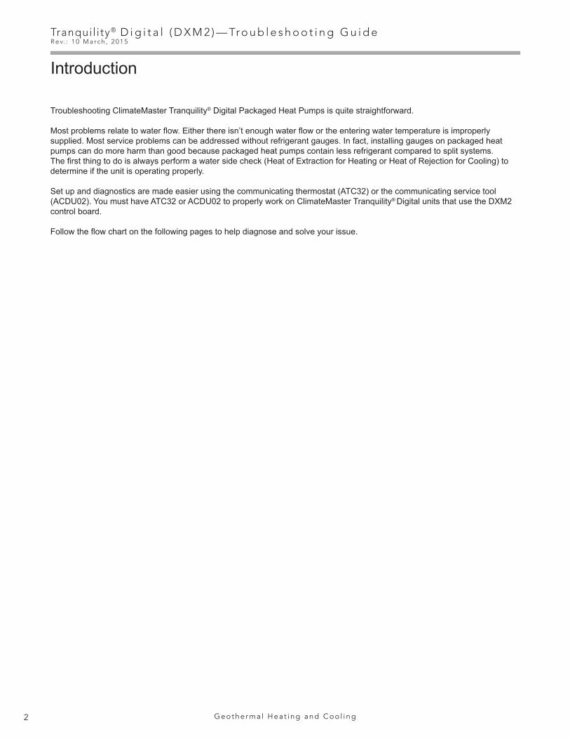
Typical Water Source Refrigeration Circuit (Heating Cycle)A-G
LT1 to LWT in HeatingTZ Units 5°-10° DifferenceTE Units 0°-8° Difference
LT1 will be colder!
Water-to-Water (Heating Only) RP932Troubleshooting Form
Customer: Loop Type: Startup Date:
Model #: Serial #: Antifreeze Type & %:
Complaint:
Description Heating NotesWater Side Analysis
1 Water In Temp.2 Water Out Temp. Temp. Diff. =3 Water In Pressure4 Water Out Pressure
4a Pressure Drop4b GPM
Heat of Extraction (Absorption) or Heat of Rejection:
HE or HR (Btuh) = Enter HE or HR:
Flow Rate (GPM) x Temp. Diff (deg F) x Fluid Factor
Refrigerant Analysis5 Suction Temp.6 Suction Pressure
6a Saturation Temp.6b Superheat7 Discharge Temp.8 Discharge Pressure
8a Saturation Temp.8b Subcooling9 Liquid Line Temp
10 Load Water In Temp.11 Load Water Out Temp. Temp. Diff. =12 Load Water In Pressure13 Load Water Out Pressure
13a Pressure Drop13b GPM
VoltageCompress Amps
COMPRESSOR
DISCHARGE
SUCTION
HWG**
EXPANSIONVALVE FILTER
DRIER*
5
COAX
42
31
8
7
6
EVAPORATOR (HEATING)
REFRIG FLOW - HEATING
Source
CO
AX
1210
1311
CONDENSER (HTG)
WATER-TO-WATER UNITS
Load
* Filter drier not used for some R-22 units.
** Turn off HWG before troubleshooting.
9 LT1:LIQUIDLINE
REFRIGERANT: R-22 R-410A
Fluid Factor:500 (Water); 485 (Antifreeze)
Unit Operating ConditionsA-G

25
Tranqui l i ty® D i g i t a l ( D X M 2 ) — Tr o u b l e s h o o t i n g G u i d eR e v. : 1 0 M a r c h , 2 0 1 5
w w w. c l i m a t e m a s t e r. c o m
Typical Water Source Refrigeration Circuit (Heating Cycle)A-G
Unit Operating ConditionsA-G
Model GPMPressure Drop (psi)
30°F* 50°F 70°F 90°F
024Rev B
2.53.03.84.56.0
0.81.21.82.73.9
0.30.61.11.62.8
0.20.50.91.22.2
0.20.50.81.22.0
030
3.03.84.56.07.5
1.72.32.73.85.1
0.91.21.62.43.5
0.81.11.42.23.1
0.81.11.42.12.9
036Rev B
4.06.06.88.09.0
0.61.82.33.24.0
0.11.01.52.22.9
0.10.71.11.82.4
0.10.71.11.72.3
042
3.85.37.57.910.5
1.72.74.54.87.4
1.01.83.13.45.4
0.91.62.83.14.9
0.91.52.62.94.7
048
4.56.06.89.012.0
1.42.02.54.06.5
1.11.72.13.45.5
0.91.41.83.04.9
0.81.31.72.74.5
060Rev B
6.07.59.012.015.0
1.22.13.15.48.1
0.91.72.54.67.0
0.81.52.34.26.4
0.81.42.23.96.1
* Based on 15% methanol antifreeze solution
TZ Coax Water Pressure DropTE Coax Water Pressure Drop
Model GPMPressure Drop (psi)
30°F 50°F 70°F 90°F
026
4.06.07.08.0
1.53.14.15.1
1.32.63.44.3
1.12.33.03.8
1.02.12.73.4
038
4.06.08.09.0
1.22.64.55.7
1.02.54.25.2
0.82.34.04.8
0.62.13.74.4
049
5.58.311.012.0
1.12.23.94.5
0.92.13.64.2
0.82.03.23.8
0.71.83.13.5
064
7.010.514.015.0
0.51.93.94.8
0.31.83.54.3
0.21.73.23.9
0.11.62.93.5
072
7.511.315.017.0
1.73.96.98.9
1.53.46.07.7
1.33.05.46.9
1.32.85.06.5
Model GPMPressure Drop (psi)
30°F 50°F 70°F 90°F
026
2.33.03.44.56.0
0.71.11.32.03.1
0.40.70.91.42.3
0.40.60.81.21.9
0.50.70.81.21.8
038
3.04.56.06.89.0
1.52.63.84.56.9
0.91.72.73.25.2
0.81.52.32.74.4
0.91.52.22.64.1
049
4.56.06.89.012.0
0.81.31.62.74.6
0.61.11.42.54.2
0.51.01.32.33.8
0.30.91.22.23.5
064
6.07.59.011.312.015.0
0.91.72.53.74.16.1
0.20.91.52.63.04.7
0.20.71.32.32.64.1
0.30.81.42.32.64.0
TES/TEP Coax Water Pressure Drop

Tranqui l i ty® D i g i t a l ( D X M 2 ) — Tr o u b l e s h o o t i n g G u i d eR e v. : 1 0 M a r c h , 2 0 1 5
26 G e o t h e r m a l H e a t i n g a n d C o o l i n g
Expansion Valve System• Feeds refrigerant based upon the measured superheat at the compressor suction. It will appropriately “meter” to maintain
superheat setting.• Able to handle a wide range of capacities (inlet water temperatures)• Bullet proof - You can’t flood a compressor by overcharging with an expansion valve in the system and thus run the risk of
compressor failure.• Stores excess refrigerant in condenser
Overcharged System• High subcooling• Superheat will be maintained by expansion valve at valve setting• Basically no change in capacity• High discharge pressure
Undercharged System• Low subcooling• High superheat• Lower capacity
TXV Stuck Closed (or Restriction)• High superheat• High subcooling• Low suction• High discharge pressure TXV Stuck Open• Low superheat• Low subcooling• High suction pressure
TXVEqualizer
Line
SuctionLine
Discharge
CopelandUltratech
Compressor
Bulb Upstreamof Equalizer Line
Proper TXV Bulb Placement
TXV
Basic Refrigeration SummaryA-H
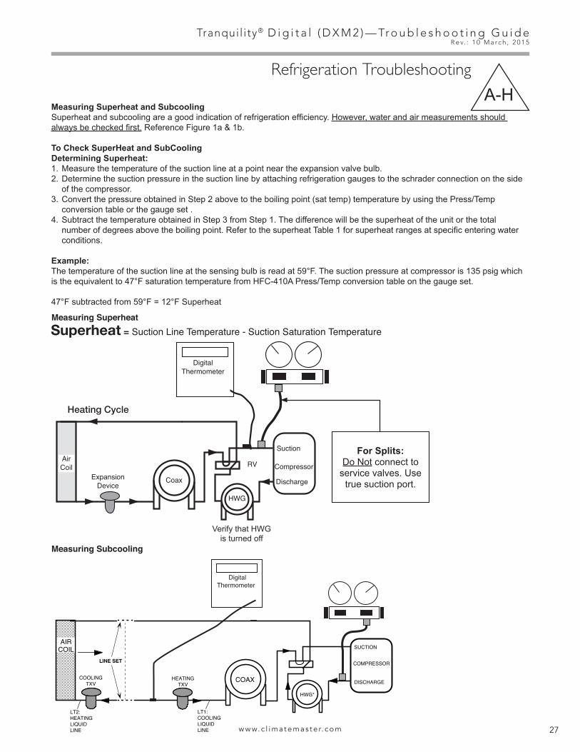
27
Tranqui l i ty® D i g i t a l ( D X M 2 ) — Tr o u b l e s h o o t i n g G u i d eR e v. : 1 0 M a r c h , 2 0 1 5
w w w. c l i m a t e m a s t e r. c o m
Basic Refrigeration SummaryA-H
Measuring Superheat and SubcoolingSuperheat and subcooling are a good indication of refrigeration efficiency. However, water and air measurements should always be checked first. Reference Figure 1a & 1b.
To Check SuperHeat and SubCoolingDetermining Superheat:1. Measure the temperature of the suction line at a point near the expansion valve bulb.2. Determine the suction pressure in the suction line by attaching refrigeration gauges to the schrader connection on the side
of the compressor. 3. Convert the pressure obtained in Step 2 above to the boiling point (sat temp) temperature by using the Press/Temp
conversion table or the gauge set . 4. Subtract the temperature obtained in Step 3 from Step 1. The difference will be the superheat of the unit or the total
number of degrees above the boiling point. Refer to the superheat Table 1 for superheat ranges at specific entering water conditions.
Example:The temperature of the suction line at the sensing bulb is read at 59°F. The suction pressure at compressor is 135 psig which is the equivalent to 47°F saturation temperature from HFC-410A Press/Temp conversion table on the gauge set.
47°F subtracted from 59°F = 12°F Superheat
Measuring Superheat
Measuring Subcooling
Refrigeration TroubleshootingA-H
CompressorExpansion
DeviceCoax
HWG
RVAirCoil
Suction
Discharge
Heating Cycle
DigitalThermometer
Superheat = Suction Line Temperature - Suction Saturation Temperature
CompressorExpansion
DeviceCoax
HWG
RVAirCoil
Suction
Discharge
Heating Cycle
DigitalThermometer
Subcooling = High Pressure Saturation Temperature - Liquid Line Temperature
Heating Liquid Line (LT2)
Cooling Liquid Line (LT1)
Verify that HWG is turned off
For Splits:Do Not connect to
service valves. Use true suction port.
COMPRESSOR
DISCHARGE
SUCTION
HWG*
AIRCOIL
COOLINGTXV COAX
LINE SET
HEATINGTXV
LT2:HEATINGLIQUIDLINE
LT1:COOLINGLIQUIDLINE
DigitalThermometer
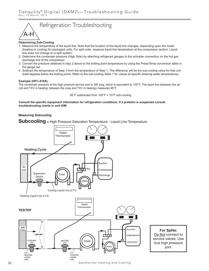
Tranqui l i ty® D i g i t a l ( D X M 2 ) — Tr o u b l e s h o o t i n g G u i d eR e v. : 1 0 M a r c h , 2 0 1 5
28 G e o t h e r m a l H e a t i n g a n d C o o l i n g
Determining Sub-Cooling:1. Measure the temperature of the liquid line. Note that the location of the liquid line changes, depending upon the mode
(heating or cooling) for packaged units. For split units, measure liquid line temperature at the compressor section. Liquid line does not change on a split system.
2. Determine the condenser pressure (High Side) by attaching refrigerant gauges to the schrader connection on the hot gas discharge line of the compressor.
3. Convert the pressure obtained in step 2 above to the boiling point temperature by using the Press/Temp conversion table or the gauge set.
4. Subtract the temperature of Step 3 from the temperature of Step 1. The difference will be the sub-cooling value for that unit (total degrees below the boiling point). Refer to the sub-cooling Table 1 for values at specific entering water temperatures.
Example (HFC-410A):The condenser pressure at the high pressure service port is 340 psig, which is equivalent to 105°F. The liquid line (between the air coil and TXV in heating; between the coax and TXV in heating) measures 95°F.
95°F subtracted from 105°F = 10°F sub-cooling
Consult the specific equipment information for refrigeration conditions. If a problem is suspected consult troubleshooting charts in unit IOM.
CompressorExpansion
DeviceCoax
HWG
RVAirCoil
Suction
Discharge
Heating Cycle
DigitalThermometer
Superheat = Suction Line Temperature - Suction Saturation Temperature
CompressorExpansion
DeviceCoax
HWG
RVAirCoil
Suction
Discharge
Heating Cycle
DigitalThermometer
Subcooling = High Pressure Saturation Temperature - Liquid Line Temperature
Heating Liquid Line (LT2)
Cooling Liquid Line (LT1)
Measuring Subcooling
TES/TEP
Refrigeration TroubleshootingA-H
For Splits:Do Not connect to
service valves. Use true high pressure
port.
COMPRESSOR
DISCHARGE
SUCTION
HWG*
AIRCOIL
COOLINGTXV COAX
LINE SET
HEATINGTXV
LT2:HEATINGLIQUIDLINE
LT1:COOLINGLIQUIDLINE
DigitalThermometer

29
Tranqui l i ty® D i g i t a l ( D X M 2 ) — Tr o u b l e s h o o t i n g G u i d eR e v. : 1 0 M a r c h , 2 0 1 5
w w w. c l i m a t e m a s t e r. c o m
Refrigeration TroubleshootingA-H
P1
Alarm
Relay
Comp
Relay
OY1 Y2 W G CR AL1
24Vd
c
EH1
EH2
P6
RC
Off
O
n
JW3
A
OVR
ESDCR N
SBAL2
JW1
Acc1
Relay
Acc2
Relay
H
CO
MN
C1
NO
1
CO
MN
C2
NO
2
P3C
ORVRVLT1
LT1
LT2
LT2
LP LPHP
HP P7
Stat
usFa
ult
R RC
C
CC
GCO
S1
S2
1 12 1 4
Factory Use
(240
Vac)
Com
N.O
.
Fan
Enab
le
5 1/
2"
7"6
1/2"
5"
Use
4 m
ount
ing
scre
ws
#6 s
heet
met
al s
crew
1” l
ong
1.5
3/8”
sta
ndof
f
Fact
ory
low
volta
ge m
olex
conn
ectio
n fo
run
it ha
rnes
s
Fact
ory
low
volta
ge m
olex
conn
ectio
n fo
rel
ectri
c he
atha
rnes
s
Mic
roU
1 Off
O
n
P2
CO
HC
OM
AO2
P11
Gnd
T1P1
0T2
T2T3
T3T4
T4T5
P9 T5T6
T6
A0-1
A0-2
Off
O
n
S3RV Re
layCC
HRe
lay
Test
P5
B-G
ndP4
A+24
V(2
40Va
c)
Fan
Spee
dN
.O.
N.C
.
12V
OU
TG
ndP8 IN NC
P12
Not
e: T
here
is o
nly
one
T1 c
onne
ctio
n
1 2 3 4
1 2 3 4 5 6 7 8
1 2 3 4 5 6 7 8
AO1
Gnd
0.5-10 VDC with Pump Running
Note: P11 is the DXM2’s output signal is to the pump.
ON
OFF
ON
OFF
1234P1
L1
L2
L3
L4
P2
Verify that 24 VDC is going to auxiliary control board.
P1
Alarm
Relay
Comp
Relay
OY1 Y2 W G CR AL1
24Vd
c
EH1
EH2
P6
RC
Off
O
n
JW3
A
OVR
ESDCR N
SBAL2
JW1
Acc1
Relay
Acc2
Relay
H
CO
MN
C1
NO
1
CO
MN
C2
NO
2
P3C
ORVRVLT1
LT1
LT2
LT2
LP LPHP
HP P7
Stat
usFa
ult
R RC
C
CC
GCO
S1
S2
1 12 1 4
Factory Use
(240
Vac)
Com
N.O
.
Fan
Enab
le
5 1/
2"
7"6
1/2"
5"
Use
4 m
ount
ing
scre
ws
#6 s
heet
met
al s
crew
1” l
ong
1.5
3/8”
sta
ndof
f
Fact
ory
low
volta
ge m
olex
conn
ectio
n fo
run
it ha
rnes
s
Fact
ory
low
volta
ge m
olex
conn
ectio
n fo
rel
ectri
c he
atha
rnes
s
Mic
roU
1 Off
O
n
P2
CO
HC
OM
AO2
P11
Gnd
T1P1
0T2
T2T3
T3T4
T4T5
P9 T5T6
T6
A0-1
A0-2
Off
O
n
S3RV Re
layCC
HRe
lay
Test
P5
B-G
ndP4
A+24
V(2
40Va
c)
Fan
Spee
dN
.O.
N.C
.
12V
OU
TG
ndP8 IN NC
P12
Not
e: T
here
is o
nly
one
T1 c
onne
ctio
n
1 2 3 4
1 2 3 4 5 6 7 8
1 2 3 4 5 6 7 8
AO1
Gnd
24 volts DCFirst stage auxiliary heat
Note: Verify second stage auxiliary heat by moving one prod to EH2
Note: If dipswitch #6 in bank S1 is turned OFF, the relays will rapidly turn on and off and will burn up the relays.
Note: On Splits, check this on the AXM Board in the Air Handler.Black
White
Red
Auxiliary Heat CheckA-I
Checking Pump OutputA-J
Note: White wire is connected to A02.

Tranqui l i ty® D i g i t a l ( D X M 2 ) — Tr o u b l e s h o o t i n g G u i d eR e v. : 1 0 M a r c h , 2 0 1 5
30 G e o t h e r m a l H e a t i n g a n d C o o l i n g
Compressor Contactor Voltage CheckA-K
Check CCH for 24 volts (Second Stage Operation)A-L
Verify that 24 volts are going to the compressor contactor.
Also verify that contactor has between 7-20 ohms across the coil with the power removed.
Verifying ContactorA-M
P1
Alarm
Relay
Comp
Relay
OY1 Y2 W G CR AL1
24Vd
c
EH1
EH2
P6
RC
Off
O
n
JW3
A
OVR
ESDCR N
SBAL2
JW1
Acc1
Relay
Acc2
Relay
H
CO
MN
C1
NO
1
CO
MN
C2
NO
2
P3C
ORVRVLT1
LT1
LT2
LT2
LP LPHP
HP P7
Stat
usFa
ult
R RC
C
CC
GCO
S1
S2
1 12 1 4
Factory Use
(240
Vac)
Com
N.O
.
Fan
Enab
le
5 1/
2"
7"6
1/2"
5"
Use
4 m
ount
ing
scre
ws
#6 s
heet
met
al s
crew
1” l
ong
1.5
3/8”
sta
ndof
f
Fact
ory
low
volta
ge m
olex
conn
ectio
n fo
run
it ha
rnes
s
Fact
ory
low
volta
ge m
olex
conn
ectio
n fo
rel
ectri
c he
atha
rnes
s
Mic
roU
1 Off
O
n
P2
CO
HC
OM
AO2
P11
Gnd
T1P1
0T2
T2T3
T3T4
T4T5
P9 T5T6
T6
A0-1
A0-2
Off
O
n
S3RV Re
layCC
HRe
lay
Test
P5
B-G
ndP4
A+24
V(2
40Va
c)
Fan
Spee
dN
.O.
N.C
.
12V
OU
TG
ndP8 IN NC
P12
Not
e: T
here
is o
nly
one
T1 c
onne
ctio
n
1 2 3 4
1 2 3 4 5 6 7 8
1 2 3 4 5 6 7 8
AO1
Gnd
18-31.5 Volts AC
P1
Alarm
Relay
Comp
Relay
OY1 Y2 W G CR AL1
24Vd
c
EH1
EH2
P6
RC
Off
O
n
JW3
A
OVR
ESDCR N
SBAL2
JW1
Acc1
Relay
Acc2
Relay
H
CO
MN
C1
NO
1
CO
MN
C2
NO
2
P3C
ORVRVLT1
LT1
LT2
LT2
LP LPHP
HP P7
Stat
usFa
ult
R RC
C
CC
GCO
S1
S2
1 12 1 4
Factory Use
(240
Vac)
Com
N.O
.
Fan
Enab
le
5 1/
2"
7"6
1/2"
5"
Use
4 m
ount
ing
scre
ws
#6 s
heet
met
al s
crew
1” l
ong
1.5
3/8”
sta
ndof
f
Fact
ory
low
volta
ge m
olex
conn
ectio
n fo
run
it ha
rnes
s
Fact
ory
low
volta
ge m
olex
conn
ectio
n fo
rel
ectri
c he
atha
rnes
s
Mic
roU
1 Off
O
n
P2
CO
HC
OM
AO2
P11
Gnd
T1P1
0T2
T2T3
T3T4
T4T5
P9 T5T6
T6
A0-1
A0-2
Off
O
n
S3RV Re
layCC
HRe
lay
Test
P5
B-G
ndP4
A+24
V(2
40Va
c)
Fan
Spee
dN
.O.
N.C
.
12V
OU
TG
ndP8 IN NC
P12
Not
e: T
here
is o
nly
one
T1 c
onne
ctio
n
1 2 3 4
1 2 3 4 5 6 7 8
1 2 3 4 5 6 7 8
AO1
Gnd
18-31.5Volts AC
Blue Blue
18 - 31.5 Volts A/C

31
Tranqui l i ty® D i g i t a l ( D X M 2 ) — Tr o u b l e s h o o t i n g G u i d eR e v. : 1 0 M a r c h , 2 0 1 5
w w w. c l i m a t e m a s t e r. c o m
Checking Pump Power CordA-O
First, remove the power to the unit and allow 5-10 minutes for the capacitor to discharge.
After discharge, remove two wires from capacity. Read UF on side and verify with volt meter that can read UF. It will also show ± range for reading.
Note: Rating will change with different size units.
Verifying CapacitorA-N
Verify 197-254V on pump power cord.
Note: Before removing cord from pump, verify that power is turned off on unit or pump will be damaged!
Note: Thermostat/service tool display may still show watts even if one leg of power to the pump (110V) is not functioning. This can result in LT1 faults in heating and high pressure faults in cooling.
Note: Do not force probes into plug. May need to use a piece of 18 guage wire into plug then check voltage.
Green White Black
Check 197-254v here

Tranqui l i ty® D i g i t a l ( D X M 2 ) — Tr o u b l e s h o o t i n g G u i d eR e v. : 1 0 M a r c h , 2 0 1 5
32 G e o t h e r m a l H e a t i n g a n d C o o l i n g
Replacing Variable-Speed Pump Power HeadA-P
1) You can remove power head from motor with # 25 Torx driver if feedback is out of range.
2) Remove plastic cover to remove Torx head screws.
Comp verify voltage 197-254V
Verifying Power at Molded Plug For CompressorA-Q

33
Tranqui l i ty® D i g i t a l ( D X M 2 ) — Tr o u b l e s h o o t i n g G u i d eR e v. : 1 0 M a r c h , 2 0 1 5
w w w. c l i m a t e m a s t e r. c o m
Verifying AntifreezeA-R
-50°F -40°F -30°F -20°F -10°F 0°F 10°F 20°F 30°F 40°F 50°F0.960
0.965
0.970
0.975
0.980
0.985
0.990
0.995
1.000
Low Temperature Protection
Spe
cific
Gra
vity
-45.6°C-40°C
-34.4°C-28.9°C
-23.3°C-17.8°C
-12.2°C-6.7°C
-1.1°C4.4°C
10°C
1.00
1.01
1.02
1.03
1.04
1.05
1.06
1.07
Low Temperature Protection
Spec
ific
Gra
vity
-40°F -30°F -20°F -10°F 0°F 10°F 20°F 30°F 40°F-40°C -34.4°C -28.9°C -23.3°C -17.8°C -12.2°C -6.7°C -1.1°C 4.4°C
0.975
0.980
0.985
0.990
0.995
1.000
-5°F 0°F 5°F 10°F 15°F 20°F 25°F 30°F 35°F
1.7°C-1.1°C-3.9°C-6.7°C-9.4°C-12.2°C-15.0°C-17.8°C-20.6°C
Low Temperature Protection
Methanol Specific Gravity Chart
Propylene Glycol Specific Gravity Chart
Ethanol Specific Gravity Chart
1) Place hydrometer in antifreeze.
2) Read hydrometer where water hits hydrometer.
3) Compare hydrometer to the charts below.
Example: 15°F Methanol = .9825 specific gravity
Read here
10° – 15° ProtectionTypical Ready Ranges
Methanol
Ethanol
Propolyene Glycol
=
=
=
.975 - .982
.981 - .982
1.025 - 1.03

Tranqui l i ty® D i g i t a l ( D X M 2 ) — Tr o u b l e s h o o t i n g G u i d eR e v. : 1 0 M a r c h , 2 0 1 5
34 G e o t h e r m a l H e a t i n g a n d C o o l i n g
Second Stage VerificationA-S
2) When rectifier is removed, verify that pins are not bent.
1) Remove rectifier.
3) Perform an amp draw and read the amps. Then remove rectifier. Amp draw should go down.
If there is no change in amps, then the compressor is not shifting.
4) With the rectifier removed from the compressor, verify 15-27 VDC.
15-27VDC

35
Tranqui l i ty® D i g i t a l ( D X M 2 ) — Tr o u b l e s h o o t i n g G u i d eR e v. : 1 0 M a r c h , 2 0 1 5
w w w. c l i m a t e m a s t e r. c o m
P1
Alarm
Relay
Comp
Relay
OY1 Y2 W G CR AL1
24Vd
c
EH1
EH2
P6
RC
Off
O
n
JW3
A
OVR
ESDCR N
SBAL2
JW1
Acc1
Relay
Acc2
Relay
H
CO
MN
C1
NO
1
CO
MN
C2
NO
2
P3C
ORVRVLT1
LT1
LT2
LT2
LP LPHP
HP P7
Stat
usFa
ult
R RC
C
CC
GCO
S1
S2
1 12 1 4
Factory Use
(240
Vac)
Com
N.O
.
Fan
Enab
le
5 1/
2"
7"6
1/2"
5"
Use
4 m
ount
ing
scre
ws
#6 s
heet
met
al s
crew
1” l
ong
1.5
3/8”
sta
ndof
f
Fact
ory
low
volta
ge m
olex
conn
ectio
n fo
run
it ha
rnes
s
Fact
ory
low
volta
ge m
olex
conn
ectio
n fo
rel
ectri
c he
atha
rnes
s
Mic
roU
1 Off
O
n
P2
CO
HC
OM
AO2
P11
Gnd
T1P1
0T2
T2T3
T3T4
T4T5
P9 T5T6
T6
A0-1
A0-2
Off
O
n
S3RV Re
layCC
HRe
lay
Test
P5
B-G
ndP4
A+24
V(2
40Va
c)
Fan
Spee
dN
.O.
N.C
.
12V
OU
TG
ndP8 IN NC
P12
Not
e: T
here
is o
nly
one
T1 c
onne
ctio
n
1 2 3 4
1 2 3 4 5 6 7 8
1 2 3 4 5 6 7 8
AO1
Gnd
18-31.5 Volts AC
Checking Reversing Valve at DXM2 A-U
Verifying 24V at Reversing ValveA-T
Verify 24V at reversing valve when calling for cooling
To check the solenoid’s magnetic pull, begin by pulling solenoid off of reversing valve. Then energize solenoid and place a metal screw driver in solenoid. You should feel the screw driver being pulled by the magnetic field.

Tranqui l i ty® D i g i t a l ( D X M 2 ) — Tr o u b l e s h o o t i n g G u i d eR e v. : 1 0 M a r c h , 2 0 1 5
36 G e o t h e r m a l H e a t i n g a n d C o o l i n g
A0-2 JumperA-V
Checking for Power at DXM2
A-W
P1
Alarm
Relay
Comp
Relay
OY1 Y2 W G CR AL1
24Vd
c
EH1
EH2
P6
RC
Off
O
n
JW3
A
OVR
ESDCR N
SBAL2
JW1
Acc1
Relay
Acc2
Relay
H
CO
MN
C1
NO
1
CO
MN
C2
NO
2
P3C
ORVRVLT1
LT1
LT2
LT2
LP LPHP
HP P7
Stat
usFa
ult
R RC
C
CC
GCO
S1
S2
1 12 1 4
Factory Use
(240
Vac)
Com
N.O
.
Fan
Enab
le
5 1/
2"
7"6
1/2"
5"
Use
4 m
ount
ing
scre
ws
#6 s
heet
met
al s
crew
1” l
ong
1.5
3/8”
sta
ndof
f
Fact
ory
low
volta
ge m
olex
conn
ectio
n fo
run
it ha
rnes
s
Fact
ory
low
volta
ge m
olex
conn
ectio
n fo
rel
ectri
c he
atha
rnes
s
Mic
roU
1 Off
O
n
P2
CO
HC
OM
AO2
P11
Gnd
T1P1
0T2
T2T3
T3T4
T4T5
P9 T5T6
T6
A0-1
A0-2
Off
O
n
S3RV Re
layCC
HRe
lay
Test
P5
B-G
ndP4
A+24
V(2
40Va
c)
Fan
Spee
dN
.O.
N.C
.
12V
OU
TG
ndP8 IN NC
P12
Not
e: T
here
is o
nly
one
T1 c
onne
ctio
n
1 2 3 4
1 2 3 4 5 6 7 8
1 2 3 4 5 6 7 8
AO1
Gnd
1) 18-31.5V A/C. Verify proper voltage to the board.
2) If there is no 24V at DXM2, verify that the breaker is not tripped on the transformer.
Ensure that the power supply to your transformer is using correct Tap (208/230).
Note: On Splits, 24V transformer is in the Air Handler connected to the AXM board then connected to DXM2.
Blue
Yellow
Red208
Orange230
BlackCommon
P1
Alarm
Relay
Comp
Relay
OY1 Y2 W G CR AL1
24Vd
c
EH1
EH2
P6
RC
Off
O
n
JW3
A
OVR
ESDCR N
SBAL2
JW1
Acc1
Relay
Acc2
Relay
H
CO
MN
C1
NO
1
CO
MN
C2
NO
2
P3C
ORVRVLT1
LT1
LT2
LT2
LP LPHP
HP P7
Stat
usFa
ult
R RC
C
CC
GCO
S1
S2
1 12 1 4
Factory Use
(240
Vac)
Com
N.O
.
Fan
Enab
le
5 1/
2"
7"6
1/2"
5"
Use
4 m
ount
ing
scre
ws
#6 s
heet
met
al s
crew
1” l
ong
1.5
3/8”
sta
ndof
f
Fact
ory
low
volta
ge m
olex
conn
ectio
n fo
run
it ha
rnes
s
Fact
ory
low
volta
ge m
olex
conn
ectio
n fo
rel
ectri
c he
atha
rnes
s
Mic
roU
1 Off
O
n
P2
CO
HC
OM
AO2
P11
Gnd
T1P1
0T2
T2T3
T3T4
T4T5
P9 T5T6
T6
A0-1
A0-2
Off
O
n
S3RV Re
layCC
HRe
lay
Test
P5
B-G
ndP4
A+24
V(2
40Va
c)
Fan
Spee
dN
.O.
N.C
.
12V
OU
TG
ndP8 IN NC
P12
Not
e: T
here
is o
nly
one
T1 c
onne
ctio
n
1 2 3 4
1 2 3 4 5 6 7 8
1 2 3 4 5 6 7 8
AO1
Gnd
For Mod Valve
For Pump A0-2 Jumper
Location
IOV PWM
IOV PWM

37
Tranqui l i ty® D i g i t a l ( D X M 2 ) — Tr o u b l e s h o o t i n g G u i d eR e v. : 1 0 M a r c h , 2 0 1 5
w w w. c l i m a t e m a s t e r. c o m
Verifying DC Voltage on DXM2 Board for Modulating Valve Check A-X
P1
Alarm
Relay
Comp
Relay
OY1 Y2 W G CR AL1
24Vd
c
EH1
EH2
P6
RC
Off
O
n
JW3
A
OVR
ESDCR N
SBAL2
JW1
Acc1
Relay
Acc2
Relay
H
CO
MN
C1
NO
1
CO
MN
C2
NO
2
P3C
ORVRVLT1
LT1
LT2
LT2
LP LPHP
HP P7
Stat
usFa
ult
R RC
C
CC
GCO
S1
S2
1 12 1 4
Factory Use
(240
Vac)
Com
N.O
.
Fan
Enab
le
5 1/
2"
7"6
1/2"
5"
Use
4 m
ount
ing
scre
ws
#6 s
heet
met
al s
crew
1” l
ong
1.5
3/8”
sta
ndof
f
Fact
ory
low
volta
ge m
olex
conn
ectio
n fo
run
it ha
rnes
s
Fact
ory
low
volta
ge m
olex
conn
ectio
n fo
rel
ectri
c he
atha
rnes
s
Mic
roU
1 Off
O
n
P2
CO
HC
OM
AO2
P11
Gnd
T1P1
0T2
T2T3
T3T4
T4T5
P9 T5T6
T6
A0-1
A0-2
Off
O
n
S3RV Re
layCC
HRe
lay
Test
P5
B-G
ndP4
A+24
V(2
40Va
c)
Fan
Spee
dN
.O.
N.C
.
12V
OU
TG
ndP8 IN NC
P12
Not
e: T
here
is o
nly
one
T1 c
onne
ctio
n
1 2 3 4
1 2 3 4 5 6 7 8
1 2 3 4 5 6 7 8
AO1
Gnd
You should see 3.3-10 Volts A/C D/C when valve is functioning properly.
The voltage relates to the valve position:Valve 0% Open = 3.30 VDCValve 50% Open = 5.00 VDCValve 100% Open = 10.00 VDC
Valve gets 24 AC volts here.Note: This check is the output to the valve from the DXM2. Red
Black
White

Tranqui l i ty® D i g i t a l ( D X M 2 ) — Tr o u b l e s h o o t i n g G u i d eR e v. : 1 0 M a r c h , 2 0 1 5
38 G e o t h e r m a l H e a t i n g a n d C o o l i n g
Suction pressure increases when warmed and decreases when bulb
is cooled in cup of ice water
Pressure Gauge
TXV Bulb TestA-Y

39
Tranqui l i ty® D i g i t a l ( D X M 2 ) — Tr o u b l e s h o o t i n g G u i d eR e v. : 1 0 M a r c h , 2 0 1 5
w w w. c l i m a t e m a s t e r. c o m
Verifying Dipswitch PositionA-Z
One of two high pressure water switches set to 145 PSI.
Note: If you are replacing a high pressure water switch, you can simply screw them off. However, beware that there is no Schrader core. To prevent water escaping when you remove the high pressure water switch, isolate the loop using flush valves in units with variable-speed pumps. To isolate the loop in units with modulating valves, use exterior ball valves.
Note: After July 2014 high pressure water switches are only in units with modulating valves.
Note: Switches are in series with high pressure refrigerant switch
Dip switch #1 in On Position for Communicating
P1
Alarm
Relay
Comp
Relay
OY1 Y2 W G CR AL1
24Vd
c
EH1
EH2
P6
RC
Off
O
n
JW3
A
OVR
ESDCR N
SBAL2
JW1
Acc1
Relay
Acc2
Relay
H
CO
MN
C1
NO
1
CO
MN
C2
NO
2
P3C
ORVRVLT1
LT1
LT2
LT2
LP LPHP
HP P7
Stat
usFa
ult
R RC
C
CC
GCO
S1
S2
1 12 1 4
Factory Use
(240
Vac)
Com
N.O
.
Fan
Enab
le
5 1/
2"
7"6
1/2"
5"
Use
4 m
ount
ing
scre
ws
#6 s
heet
met
al s
crew
1” l
ong
1.5
3/8”
sta
ndof
f
Fact
ory
low
volta
ge m
olex
conn
ectio
n fo
run
it ha
rnes
s
Fact
ory
low
volta
ge m
olex
conn
ectio
n fo
rel
ectri
c he
atha
rnes
s
Mic
roU
1 Off
O
n
P2
CO
HC
OM
AO2
P11
Gnd
T1P1
0T2
T2T3
T3T4
T4T5
P9 T5T6
T6
A0-1
A0-2
Off
O
n
S3RV Re
layCC
HRe
lay
Test
P5
B-G
ndP4
A+24
V(2
40Va
c)
Fan
Spee
dN
.O.
N.C
.
12V
OU
TG
ndP8 IN NC
P12
Not
e: T
here
is o
nly
one
T1 c
onne
ctio
n
1 2 3 4
1 2 3 4 5 6 7 8
1 2 3 4 5 6 7 8
AO1
Gnd
Replacing High Pressure Water SwitchB-A
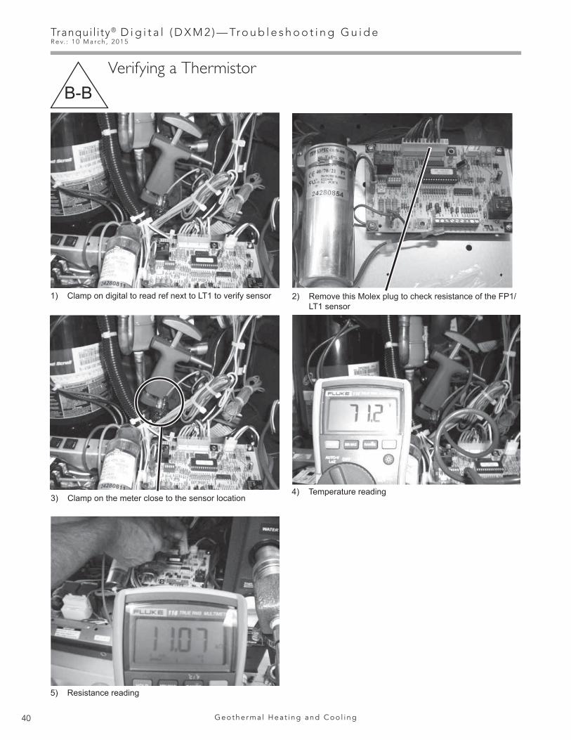
Tranqui l i ty® D i g i t a l ( D X M 2 ) — Tr o u b l e s h o o t i n g G u i d eR e v. : 1 0 M a r c h , 2 0 1 5
40 G e o t h e r m a l H e a t i n g a n d C o o l i n g
1) Clamp on digital to read ref next to LT1 to verify sensor
Verifying a ThermistorB-B
2) Remove this Molex plug to check resistance of the FP1/LT1 sensor
3) Clamp on the meter close to the sensor location4) Temperature reading
5) Resistance reading

41
Tranqui l i ty® D i g i t a l ( D X M 2 ) — Tr o u b l e s h o o t i n g G u i d eR e v. : 1 0 M a r c h , 2 0 1 5
w w w. c l i m a t e m a s t e r. c o m
Nominal resistance at various temperatures Table
Verifying a ThermistorB-B
1% Sensor Calibration Points Table
Thermistor Temperature Sensors – The thermistors used with the DXM2 are NTC (negative temperature coefficient) type. Table 7 shows the replacement part numbers for the LT1 and LT2 thermistors. The sensors have a 1% tolerance and follow the characteristics shown in ‘1% Sensor Calibration Points Table’. The ‘Nominal resistance at various temperatures Table’ shows the nominal resistance at any given temperature and can be used for field service reference. The sensor will use a minimum of 24 awg wire.
Temp (ºC) Temp (ºF) Resistance (kOhm) Temp (ºC) Temp (ºF) Resistance
(kOhm)-17.8 0.0 85.34 55 131.0 2.99-17.5 0.5 84.00 56 132.8 2.88-16.9 1.5 81.38 57 134.6 2.77-12 10.4 61.70 58 136.4 2.67-11 12.2 58.40 59 138.2 2.58-10 14.0 55.30 60 140.0 2.49-9 15.8 52.38 61 141.8 2.40-8 17.6 49.64 62 143.6 2.32-7 19.4 47.05 63 145.4 2.23-6 21.2 44.61 64 147.2 2.16-5 23.0 42.32 65 149.0 2.08-4 24.8 40.15 66 150.8 2.01-3 26.6 38.11 67 152.6 1.94-2 28.4 36.18 68 154.4 1.88-1 30.2 34.37 69 156.2 1.810 32.0 32.65 70 158.0 1.751 33.8 31.03 71 159.8 1.692 35.6 29.50 72 161.6 1.643 37.4 28.05 73 163.4 1.584 39.2 26.69 74 165.2 1.535 41.0 25.39 75 167.0 1.486 42.8 24.17 76 168.8 1.437 44.6 23.02 77 170.6 1.398 46.4 21.92 78 172.4 1.349 48.2 20.88 79 174.2 1.30
10 50.0 19.90 80 176.0 1.2611 51.8 18.97 81 177.8 1.2212 53.6 18.09 82 179.6 1.1813 55.4 17.26 83 181.4 1.1414 57.2 16.46 84 183.2 1.1015 59.0 15.71 85 185.0 1.0716 60.8 15.00 86 186.8 1.0417 62.6 14.32 87 188.6 1.0118 64.4 13.68 88 190.4 0.9719 66.2 13.07 89 192.2 0.9420 68.0 12.49 90 194.0 0.9221 69.8 11.94 91 195.8 0.8922 71.6 11.42 92 197.6 0.8623 73.4 10.92 93 199.4 0.8424 75.2 10.45 94 201.2 0.8125 77.0 10.00 95 203.0 0.7926 78.8 9.57 96 204.8 0.7627 80.6 9.16 97 206.6 0.7428 82.4 8.78 98 208.4 0.7229 84.2 8.41 99 210.2 0.7030 86.0 8.06 100 212.0 0.6831 87.8 7.72 101 213.8 0.6632 89.6 7.40 102 215.6 0.6433 91.4 7.10 103 217.4 0.6234 93.2 6.81 104 219.2 0.6035 95.0 6.53 105 221.0 0.5936 96.8 6.27 106 222.8 0.5737 98.6 6.01 107 224.6 0.5538 100.4 5.77 108 226.4 0.5439 102.2 5.54 109 228.2 0.5240 104.0 5.33 110 230.0 0.5141 105.8 5.12 111 231.8 0.5042 107.6 4.92 112 233.6 0.4843 109.4 4.72 113 235.4 0.4744 111.2 4.54 114 237.2 0.4645 113.0 4.37 115 239.0 0.4446 114.8 4.20 116 240.8 0.4347 116.6 4.04 117 242.6 0.4248 118.4 3.89 118 244.4 0.4149 120.2 3.74 119 246.2 0.4050 122.0 3.60 120 248.0 0.3951 123.8 3.47 121 249.8 0.3852 125.6 3.34 122 251.6 0.3753 127.4 3.22 123 253.4 0.3654 129.2 3.10
Example: See images 4 and 5 on previous page.
If your temperature reading is 71.2 with 11.07 ohms, your sensor is good.
All thermistors in Tranquility® units can use this chart for verification
Temp (°F)
Minimum Resistance
(Ohm)
Maximum Resistance
(Ohm)
Nominal Resistance
(Ohm)78.5 9523 9715 9619
77.5 9650 9843 9746
76.5 10035 10236 10135
75.5 10282 10489 10385
33.5 30975 31598 31285
32.5 31871 32512 32190
31.5 32653 33310 32980
30.5 33728 34406 34065
1.5 80624 82244 81430
0.5 83327 85002 84160
0.0 84564 86264 85410

Tranqui l i ty® D i g i t a l ( D X M 2 ) — Tr o u b l e s h o o t i n g G u i d eR e v. : 1 0 M a r c h , 2 0 1 5
42 G e o t h e r m a l H e a t i n g a n d C o o l i n g
ON
OFF
ON
OFF
1234P1
L1
L2
L3
L4
P2
197 - 254 V
Turning Breaker on in Panel or Auxiliary Heat ControlB-C
Static Pressure CheckB-D
ReturnAir
SupplyAir
Static Pressure Probeinserted into 1/2” Hole
-.18 + .21
With the blower at full load air speed, take a reading from the Digital Manameter. Check the reading against the IOM blower tables or in the tables shown below to determine the maximum external static pressure.
Verify that all grilles and registers are open and free.
Use a Magnetic Static Pressure Tip tool (far right) to check the static pressure.
Add both together to get Total StaticExample: .39 Static Pressure
Tranquility® 22 (TZ) SeriesAirflow in CFM with wet coil and clean air filter
Model Max ESP (in. wg)
024 0.75
030 0.5
036 0.6
042 0.6
048 0.75
060 0.75
Airflow is controlled within 5% up to the Max ESP shown with wet coil.Factory shipped on default CFM.
Tranquility® 30 (TE) SeriesAirflow in CFM with wet coil and clean air filter
ModelMax ESP
(in. wg)026 1.0
038 0.9
049 1.0
064 0.7
072 0.7
Airflow is controlled within 5% up to the Max ESP shown with wet coil.
ECM Blower Performance Static Pressure Tables
Magnetic Static Pressure Tip
Tranquility® Digital Air Handler (TAH)
Model Max ESP (in. wg)
026 1.0
038 0.9
049 1.0
064 0.7

43
Tranqui l i ty® D i g i t a l ( D X M 2 ) — Tr o u b l e s h o o t i n g G u i d eR e v. : 1 0 M a r c h , 2 0 1 5
w w w. c l i m a t e m a s t e r. c o m
Locating Thermostat Version and DXM2 VersionB-E
INSTALLER SETTINGSTHERMOSTAT CONFIGSYSTEM CONFIGACCESSORY CONFIGINPUT DEALER INFOHUMIDITY CONFIGTEMPERATURE CONTROLDEMAND REDUCTION CNFGSERVICE MODERESTORY DEFAULTS
DXM2 3.3ATC32U02 C 1.0SELECT OPTION PREVIOUS
Locate the version level of the DXM2 board and thermostat or service tool on the screen. You can locate the part number on the board and compare it to the table below.
Note: In the future, if there are software changes, the part number will also change.
UltraCheck - EZ™ Motor Diagnostic ToolB-F
Program History of DXM2Part Number / Dots Version Number
17B002N10Version 3.6Version 3.3
17B0002N06
Version 1.217B0002N0517B0002N02
with 3 Yellow Dots2 Yellow Dots1 Yellow Dot Version 1.13 Gray Dots Version 1.02 Gray Dots Version 0.31 Gray Dot
Shows up as nothingNo Dots
EZ TOOLOrange Power Button
Green LED
Motor Blower Comments
Not Lit Not Lit Not Rotating
If button does not illuminate when power button is depressed, verify 24Vac is available at alligator
clips. If 24Vac is verified, the UltraCheck-EZ diagnostic tool is inoperable.
Lit Blinking Rotating Motor and control unit are functioning properly.Lit Not Lit Rotating Control unit should be replaced
Lit Blinking Not Rotating Further investigation required. Proceed to check IV to verify motor operation.
Lit Not Lit Not Rotating Control unit should be replaced, proceed to check IV to verify the motor is still operational.
Note: Any board version lower than 3.3 should be replaced if experiencing any odd symptoms or lockouts that are unexplained

Tranqui l i ty® D i g i t a l ( D X M 2 ) — Tr o u b l e s h o o t i n g G u i d eR e v. : 1 0 M a r c h , 2 0 1 5
44 G e o t h e r m a l H e a t i n g a n d C o o l i n g
Magnet Test to Shift Reversing Valve into CoolingB-H
Checking Dipswitches on DXM2B-G
Use a magnet to pull the internal slide to one side or another.
Verify that dipswitch number 1 is in the ‘On’ position.
If dipswitch number 1 is in the ‘Off’ position, the thermostat will not function.
Under most residential situations, dipswitch banks 1 and 2 will all be in the ‘On’ position.
If any of these dipswitches need to be switched to ‘Off’, consult the DXM2 AOM (97B0003N15).
Discharge line
Line to air coil
Line to coax
Line to compressor
(suction)
Strong magnet placed on air
coil side

45
Tranqui l i ty® D i g i t a l ( D X M 2 ) — Tr o u b l e s h o o t i n g G u i d eR e v. : 1 0 M a r c h , 2 0 1 5
w w w. c l i m a t e m a s t e r. c o m
Checking Blower Line VoltageB-I
For a Modulating Valve that Loses Configuration on Thermostat B-J
In order to have your thermostat acknowledge that the unit has a modulating valve instead of incorrectly showing a variable-speed pump, connect a piece of thermostat wire between GND and T1 so the DXM2 board does not see feedback.
Note: Be sure to turn power off when removing and reinstalling harness to motor or damage will occur.
197-254V
P1
Alarm
Relay
Comp
Relay
OY1 Y2 W G CR AL1
24Vd
c
EH1
EH2
P6
RC
Off
O
n
JW3
A
OVR
ESDCR N
SBAL2
JW1
Acc1
Relay
Acc2
Relay
H
CO
MN
C1
NO
1
CO
MN
C2
NO
2
P3C
ORVRVLT1
LT1
LT2
LT2
LP LPHP
HP P7
Stat
usFa
ult
R RC
C
CC
GCO
S1
S2
1 12 1 4
Factory Use
(240
Vac)
Com
N.O
.
Fan
Enab
le
5 1/
2"
7"6
1/2"
5"
Use
4 m
ount
ing
scre
ws
#6 s
heet
met
al s
crew
1” l
ong
1.5
3/8”
sta
ndof
f
Fact
ory
low
volta
ge m
olex
conn
ectio
n fo
run
it ha
rnes
s
Fact
ory
low
volta
ge m
olex
conn
ectio
n fo
rel
ectri
c he
atha
rnes
s
Mic
roU
1 Off
O
n
P2
CO
HC
OM
AO2
P11
Gnd
T1P1
0T2
T2T3
T3T4
T4T5
P9 T5T6
T6
A0-1
A0-2
Off
O
n
S3RV Re
layCC
HRe
lay
Test
P5
B-G
ndP4
A+24
V(2
40Va
c)
Fan
Spee
dN
.O.
N.C
.
12V
OU
TG
ndP8 IN NC
P12
Not
e: T
here
is o
nly
one
T1 c
onne
ctio
n
1 2 3 4
1 2 3 4 5 6 7 8
1 2 3 4 5 6 7 8
AO1
Gnd

Tranqui l i ty® D i g i t a l ( D X M 2 ) — Tr o u b l e s h o o t i n g G u i d eR e v. : 1 0 M a r c h , 2 0 1 5
46 G e o t h e r m a l H e a t i n g a n d C o o l i n g
Hard Reset of ThermostatB-K
Use a thermostat wire to connect TP2 and TP3 on the thermostat board.

47
Tranqui l i ty® D i g i t a l ( D X M 2 ) — Tr o u b l e s h o o t i n g G u i d eR e v. : 1 0 M a r c h , 2 0 1 5
w w w. c l i m a t e m a s t e r. c o m
Units Having LT1 Lockouts In Heating with Modulating Valve (Open Loop) B-L
When running unit in Y1 and Y2, if valve position moves slightly below 50% open, there is a greater impact on GPM. Putting a pressure-reducing valve ahead of heat pump will prevent valve from moving below 50% open. Set pressure reducing valve to 30 PSI.
Water OutShut Off
Ball Valves for Isolation
Water In
WellTank
BoilerDrains
Pressure-ReducingValve - 30 PSI
50 - 70 PSITypical HouseholdPressure for Wells

Tranqui l i ty® D i g i t a l ( D X M 2 ) — Tr o u b l e s h o o t i n g G u i d eR e v. : 1 0 M a r c h , 2 0 1 5
48 G e o t h e r m a l H e a t i n g a n d C o o l i n g
Electrical—Power WiringB-M
Electrical—Power WiringB-N
Remove Harness Plug
Note: For 115v power only. Damage will occur to motor with 230v power supply if 115v jumper is used.
Install Two Pin Jumper Plug
Note: Check the unit voltage with the harness connected and unit powered up.
DXM2AXM
9-15V DC9-15V DC

49
Tranqui l i ty® D i g i t a l ( D X M 2 ) — Tr o u b l e s h o o t i n g G u i d eR e v. : 1 0 M a r c h , 2 0 1 5
w w w. c l i m a t e m a s t e r. c o m
LT2 Sensor Location for Non-TAH Air HandlersB-O
Air Coil ConnectionB-P
Lineset Diameters and Charge InformationB-Q
Do not install LT2 sensor on this tube
Place LT2 here using a 5/8” clip
PN: 17B0032N03
Sensing BulbIMPORTANT: DO NOT perform any brazing with the TXV bulb attached to any line. After brazing operations have been completed, clamp the TXV bulb securely on the suction line at the 10 or 2 o’clock position with the strap provided in the parts bag. Insulate the TXV sensing bulb and suction line with the provided pressure sensitive insulation (size 4” x 7”).IMPORTANT: TXV sensing bulb should be located on a horizontal section of suction line, just outside of coil box.IMPORTANT: Always protect TXV from heat when brazing.IMPORTANT: TXV sensing bulb is shipped unattached. Installer must attach bulb to suction line after brazing and cooling line for proper unit operation.
TXV (‘IN’ towardcompressor section)
Suction Line
Liquid Line
Bulb (Must beInstalled andInsulated)
EqualizerLine
TXV has internalcheck valve
LT2Sensor
• Basic charge includes only the amount required for the condensing unit and the evaporating coil. An additional amount should be added allowing 0.6oz per ft. for 3/8” [0.6g per cm] and 1.2oz per ft. for 1/2” [1.1g per cm] of lineset used.†Factory charge is preset for 25’ [7.6 meters] lineset.
ModelFactory†
Charge (oz) [kg]
Basic*Charge (oz)
[kg]
20 Feet [6 meters] 40 Feet [12 meters] 60 Feet [18 meters]
Liquid Suction Liquid Suction Liquid Suction
TES/TEP Series026 93 [2.64] 78 [2.21] 3/8" 3/4" 3/8" 3/4" 3/8" 3/4"
038 120 [3.40] 105 [2.98] 3/8" 7/8" 3/8" 7/8" 3/8" 7/8"
049 137 [3.88] 122 [3.46] 3/8" 7/8" 3/8" 7/8" 3/8" 7/8"
064 212 [6.01] 182 [5.16] 1/2" 7/8" 1/2" 7/8" 1/2" 7/8"

Tranqui l i ty® D i g i t a l ( D X M 2 ) — Tr o u b l e s h o o t i n g G u i d eR e v. : 1 0 M a r c h , 2 0 1 5
50 G e o t h e r m a l H e a t i n g a n d C o o l i n g
Connection to Non-Communicating thermostat and AXM communicating control in Tranquility® Digital Air Handler
B-R
68.
Non-Communicating2 Cool / 3 Heat Thermostat
CompressorCompressor Stage 2
CommunicatingTAH AXM Control
Y1Y2
ORGC
DHAL1
Y1Y2
Non-communicating thermostat with communicating compressor section and communicating air handler
DXM2 InCompressor
Section
Fault LED L
Reversing Valve OWAuxiliary Heat W
24Vac Hot RFan G
24Vac Common CDHDehumidification
(ATP32U04 Only)
CA+B-
24V
CA+B-
24V
Non-Communicating2 Cool / 3 Heat Thermostat
CompressorCompressor Stage 2
CommunicatingTAH AXM Control
Y1Y2
ORGC
DHAL1
Y1Y2
Non-communicating thermostat with communicating compressor section and communicating air handler
DXM2 InCompressor
Section
Fault LED L
Reversing Valve OWAuxiliary Heat W
24Vac Hot RFan G
24Vac Common CDHDehumidification
(ATP32U04 Only)
CA+B-
CA+B-
24V 24V
ATC32U02
24V
B-
A+
C
Thermostat ConnectionsC 24V Common for Control CircuitR 24V Supply for Control CircuitA+ Communications (Positive)B – Communications (Negative)
Non CLMTypical Thermostat
CompressorCompressor Stage 2
Non CLMTypical
Air HandlerY1
Y2
O
R
G
C
Y1
Y2
DXM2 BoardCompressor
Section
Electric Heat W
Reversing Valve O24Vac Hot R
Fan G24Vac Common C
AL1Alarm
EElectric Heat
L
W2W1
Y1
Y2
O
R
G
C
LT2Sensor
LT2
LT2Air Coil Freeze
Protection
Note: LT2 sensor is shipped on both TES and TEP.Thermostat ConnectionsC 24V Common for Control CircuitR 24V Supply for Control CircuitA+ Communications (Positive)B – Communications (Negative)

51
Tranqui l i ty® D i g i t a l ( D X M 2 ) — Tr o u b l e s h o o t i n g G u i d eR e v. : 1 0 M a r c h , 2 0 1 5
w w w. c l i m a t e m a s t e r. c o m
Definitions of Conditions
CONTACTOR OPEN - NOT BUZZINGWhen the contactor is open but not buzzing, it is an indication of no voltage to its coil, or that there is voltage to its coil but the coil is open circulated. If unit does not start, check volt-age at coil with volt meter. If there is voltage, the coil is open circulated. Replace the contactor. If no voltage, check power to control circuit.
LOW SUCTION PRESSUREIf low suction pressure is suspected, switch to heating mode and check the suction pressure. This suction pressure should not be lower than the refrigerant pressure equivalent to enter-ing water temperature minus 40°F, provided there is ad-equate water flow and entering air is approximately at 70°F.
OPEN HIGH PRESSURE SWITCHIt is factory set to shut down the unit at 600 PSI.
EXCESSIVE DISCHARGE PRESSUREIf excessive discharge pressure is suspected, switch to heat-ing mode and check the discharge pressure. This discharge pressure should not be higher than the refrigerant pressure equivalent to entering air dry bulb temperature plus 60°F, pro-vided there is proper air flow and entering water temperature is approximately at 70°F.
COMPRESSOR OVERLOADS OPEN AND CLOSEThe purpose of overloads is to quickly sense excessive compressor current and/or temperature and open the power circuit to prevent burnout of motor. This condition may be caused by repeated call to start before pressures equalize, low voltage, tightness of new compressor, excessive current draw or the temperature of the suction gas being too warm to adequately cool the motor. Warm suction gas may be due to an under charge, too much superheat, restriction in liquid or suction line, or restriction in capillary. When the overload opens, it may take from 5 to 30 minutes for it to cool suffi-ciently to close.
CONTACTOR OPEN - BUZZINGWhen the contactor is open but buzzing, it is an indication that its coil is energized but the contactor is unable to close.
NORMAL VOLTAGE TO COILCheck voltage to coil. It should not be lower than 10% below rated voltage as the contractor tries to close. If voltage is normal, the mechanism may be tight or fouled. Remove and inspect mechanism. Clean if necessary. If too sluggish, replace contactor.
BELOW NORMAL VOLTAGE TO COILCheck voltage to coil. If it is lower than 10% below rated volt-age, it is probably due to low supply voltage, faulty trans-former or phase loss.
OPEN OVERLOAD SWITCHSometimes overloads will fail with contacts in the open posi-tion, or contacts may be closed but not conducting electri-cally. To check this, disconnect power circuit. If unit starts,
replace overload if it is located in the electrical box. If unit does not start, the trouble is elsewhere.
BURNED CONTACTSSometimes contacts will close mechanically but will not con-duct electrically. To check for this, disconnect power circuit and measure contact resistance with ohmmeter. The meter should read zero ohms. If meter does not read zero ohms, replace contactor. If ohmmeter is not available, disconnect power circuit, place temporary jumpers from line side of con-tacts and close power circuit. If unit starts, replace contactor. If unit does not start, trouble is elsewhere. Burned contacts may also cause high current draw.
EXPANSION VALVE BULB LOST CHARGEIf the bulb of the expansion valve loses its charge, there will be no pressure to open the valve, thus causing low suction pressure. To check this, remove expansion valve bulb from suction line and hold it in your hand. If the suction pressure does not increase in a few minutes and there are no restrictions in the refrigerant circuit, it is an indication that the bulb has lost its charge. Replace expansion valve.
DISTRIBUTOR TUBE RESTRICTEDTo check this, check suction pressure (very low suction pressure is an indication of restriction or excessive under charge) on cooling cycle temporarily cut off air to air coil and allow unit to operate. If there is a partial restriction or exces-sive undercharge, frost will occur at that point. If there is no restriction, the evaporator coil will frost uniformly. If there is a total restriction anywhere in the refrigerant circuit from the condenser through the evaporator and back to the com-pressor, there will be no frost, the suction pressure may go into vacuum and the discharge pressure will correspond to approximately ambient temperature because there will be no vapor to compress.
EXCESSIVE SUPERHEATSuperheat is the temperature of the refrigerant vapor above the temperature corresponding to the vapor pressure. It should be 3° to 25°F. Excessive superheat is an indication that the evaporator is “starved”. That is, not enough liquid refrigerant in the coil. Excessive superheat may be due to undercharge, restriction in refrigerant circuit, low discharge pressure, expansion valve bulb lost charge, too much load on evaporator, or refrigerant flashing ahead of expansion valve or capillary due to pressure drop.
HIGH AMPSRefer to nameplate on unit. Amps should not exceed rating more than 10%.
POOR EXPANSION VALVE BULB INSTALLATIONThe expansion valve bulb should be securely mounted and properly located on clean pipe, paral-lel to pipe with firm metal contact and wrapped with insulation tape to assure proper sensing of suction line temperature.
A-Y
A-H
Tranqui l i ty® D i g i t a l ( D X M 2 ) — Tr o u b l e s h o o t i n g G u i d eR e v. : 1 0 M a r c h , 2 0 1 5
52 G e o t h e r m a l H e a t i n g a n d C o o l i n g
Definitions of Conditions
MOTOR WINDINGS OVERHEATEDWhen the compressor is drawing normal amps and becomes overheated and cycles by the overload, it is due to the tem-perature of the suction gas being too high to remove heat from the compressor motor. This in turn is due to under-charge, superheat too high or restriction in refrigerant circuit.
HIGH OR LOW VOLTAGECheck nameplate on unit for voltage rating. Check voltage at contactor or starter while the unit is operating. This volt-age should not vary by more than 10% plus or minus from nameplate.
EXPANSION VALVE EQUALIZER LINE RESTRICTEDCheck the equalizer line visually for external damage.
EXPANSION VALVE DIAPHRAGM CASE COLDER THAN THE BULBIf the diaphragm case becomes colder than the bulb, the charge will leave the bulb and condense in the diaphragm case. Thus, bulb control will be lost.

53
Tranqui l i ty® D i g i t a l ( D X M 2 ) — Tr o u b l e s h o o t i n g G u i d eR e v. : 1 0 M a r c h , 2 0 1 5
w w w. c l i m a t e m a s t e r. c o m
DXM2 Board Layout and Dipswitches
P1
Alarm Relay
Comp Relay
OY1 Y2 W G CR AL1
24Vd
c
EH1
EH2
P6
RC
Off
O
n
JW3
A
OVR
ESDCR N
SBAL2
JW1
Acc1 Relay Acc2 Relay
H
CO
M1
NC
1N
O1
CO
M2
NC
2N
O2
P3C
ORVRVLT1
LT1
LT2
LT2
LP LPHP
HP P7
Stat
usFa
ult
R RC
C
CC
GCO
S1
S2
1 12 1 4
esU yrotcaF
Com
N.O.
Fan Enable
5 1/
2"
7"6
1/2"
5"
Use
4 m
ount
ing
scre
ws
#6 s
heet
met
al s
crew
1” l
ong
Fact
ory
low
volta
ge m
ole
conn
ectio
n fo
run
it ha
rnes
s
Fact
ory
low
volta
ge m
olex
conn
ectio
n fo
rel
ectri
c he
atha
rnes
s
MicroU1
Off
O
n
P2
CO
HC
OM
AO2
P11 G
ndT1
P10
T2T2
T3T3
T4T4
T5
P9T5
T6T6
A0-1
A0-2
Off
O
n
S3
RV Relay
CCH Relay
Test
P5
B-G
ndP4
A+24
V
(240Vac)Fan Speed
N.O.N.C.
12V
OU
TG
ndP8 IN NC
P12
Not
e: T
here
is o
nly
one
T1 c
onne
ctio
n
1 2 3 4
1 2 3 4 5 6 7 8
1 2 3 4 5 6 7 8
Service toolconnection
Communicatingstat connection
Conventionalstat connection
Cabinet temperature sensor (with variable speed pump)
24V to compressor second-stage solenoid for Y2/fullload capacity
Use 4 mounting screws #6 sheet metal screw 1” long
Configure modulating valve or variablespeed pump
Variable speed pump
Entering water temp
Leaving water temp
Leavingair temp
Electric heatconnection
Factory low voltage molex connection for unit harness
Entering Hot waterTemperature
Compressor DischargeTemperature
ECM Motor Connection
Test Button to Speed up Time Delays
Communicationsand HWG Settings
Water CoilLow TempLimit Setting.JWT-LT1 jumpershould be clippedfor low temp(antifreeze) operation
Accessoryrelays referto DXM2 AOMfor configuration
(240Vac)
AO1
Gnd
(Packaged units)

Tranqui l i ty® D i g i t a l ( D X M 2 ) — Tr o u b l e s h o o t i n g G u i d eR e v. : 1 0 M a r c h , 2 0 1 5
54 G e o t h e r m a l H e a t i n g a n d C o o l i n g
Fan Connections
Electric HeatConnections
9-wire connection to non-communicating thermostat/
compressor section
4-wire connection to communicating thermostat
4-wire connection to DXM2
Accessory outputs
that track blower
operation
LT2 Sensor
CondensateSensor
AXM Board Layout and Dipswitches

55
Tranqui l i ty® D i g i t a l ( D X M 2 ) — Tr o u b l e s h o o t i n g G u i d eR e v. : 1 0 M a r c h , 2 0 1 5
w w w. c l i m a t e m a s t e r. c o m
DXM2 Controls
FIELD SELECTABLE INPUTSTest mode: Test mode allows the service technician to check the operation of the control in a timely manner. By momen-tarily pressing the TEST pushbutton, the DXM2 control enters a 20 minute test mode period in which all time delays are sped up 15 times. Upon entering test mode, the Status and Fault LED displays will change. The Status LED will ei-ther flash rapidly to indicate the control is in the test mode, or display a numeric flash code representing the current airflow if an ECM blower is connected and operating. The Fault LED will display the most recent fault condition in memory. Note: A flash code of 1 indicates there have been no faults stored in memory.
For diagnostic ease at conventional thermostats, the alarm relay will also cycle during test mode. The alarm relay will cycle on and off similar to the Fault LED to indicate a code representing the last fault, at the thermostat.
The test mode can be exited by pressing the TEST pushbut-ton for 3 seconds. The test Mode can also be entered and exited by cycling the G input, 3 times within a 60 second time period.
During Test Mode, the control monitors to see if the LT1 and LT2 thermistors are connected and operating properly. If the control is in Test Mode, the control will lockout, with Code 9, after 60 seconds if:
a) the compressor is On in Cooling Mode and the LT1 sen-sor is colder than the LT2 sensor. or,
b) the compressor is On in Heating Mode and the LT2 sen-sor is colder than the LT1 sensor.
Retry Mode: If the control is attempting a retry of a fault, the Fault LED will slow flash (slow flash = one flash every 2 sec-onds) to indicate the control is in the process of retrying.
Field Configuration Options - Note: In the following field configuration options, jumper wires should be clipped ONLY when power is removed from the DXM2 control.
Note: Jumper 3 must not be clipped prior to adding antifreeze to the water loop. Antifreeze protection to 10°F required. Clipping JW3 without antifreeze may result in freeze damage and will void the unit warranty.
Water coil low temperature limit setting: Jumper 3 (JW3-LT1 Low Temp) provides field selection of temperature limit setting for LT1 of 30°F or 10°F [-1°F or -12°C] (refrigerant temperature).
Not Clipped = 30°F. Clipped = 10°F.
Alarm Relay Setting - Jumper 1 (JW1-AL2 Dry) provides field selection of alarm function when Alarm Relay is ener-gized.
Not Clipped = AL1 connected to R (24VAC) with Alarm Relay active.
Clipped = Dry contact connection between AL1 and AL2 with Alarm Relay active.
JUMPERS (Set at Factory)
A0-2: Configure Modulating Valve or Variable-Speed Pump (vFlow™ Models Only)
Set A0-2 jumper (see Figure on page 5) to “0 - 10v” if using Internal Modulating Motorized Valve or “PWM” if using Inter-nal Variable-Speed Pump. This applies only to vFlow™ units with Internal Speed Water Flow Control.
DIP SWITCHES
Note: In the following field configuration options, DIP switches should only be moved when power is removed from the DXM2 Control to ensure proper operation.
DIP Package #1 (S1)
DIP Package #1 is 8 position and provides the following setup selections.
DIP 1.1: Unit Performance Sentinel Disable - Provides field selection to disable the UPS feature.
On = Enabled. Off = Disabled.
DIP 1.2: Compressor Relay Staging Operation - Provides selection of Compressor Relay staging operation. The Compressor Relay can be selected to turn on with Stage 1 or Stage 2 call from the thermostat. This is used with Dual Stage units (2 compressors where 2 DXM2 Controls are being used) or with master/slave applications. In master/slave applications, each compressor and fan will stage according to its appropriate DIP 1.2. If set to stage 2, the compressor will have a 3 second on-delay before energizing during a Stage 2 demand. Also, if set for stage 2, the Alarm Relay will NOT cycle during Test Mode.
On = Stage 1. Off = Stage 2.
DIP 1.3: Thermostat Type (Heat/Cool) - Provides selection of thermostat type. Heat Pump or Heat/Cool thermostats can be selected. When in Heat/Cool Mode, Y1 is input call for Cooling Stage 1, Y2 is input call for Cooling Stage 2, W1 is input call for Heating Stage 1, and O/W2 is input call for Heating Stage 2. In Heat Pump Mode, Y1 is input call for Compressor Stage 1, Y2 is input call for Compressor Stage 2, W1 is input call for Heating Stage 3 or Emergency Heat, and O/W2 is the input call for RV (heating or cooling dependent upon DIP 1.4).
On = Heat Pump. Off = Heat/Cool.
DIP 1.4: Thermostat Type (O/B) - Provides selection of thermostat type. Heat pump thermostats with “O” output on with Cooling or “B” output on with Heating can be selected.
On = HP Stat with O output with cooling. Off = HP Stat with B output with heating.
DIP 1.5: Dehumidification Mode - Provides selection of normal or Dehumidification Fan Mode. In Dehumidification Mode, the fan speed will be adjusted for Cooling. In Normal Mode, the fan speed will be normal during Cooling.

Tranqui l i ty® D i g i t a l ( D X M 2 ) — Tr o u b l e s h o o t i n g G u i d eR e v. : 1 0 M a r c h , 2 0 1 5
56 G e o t h e r m a l H e a t i n g a n d C o o l i n g
Table 2: Accessory Relay 2 Configuration
Table 1: Accessory Relay 1 Configuration
DXM2 Controls
On = Normal Fan Mode. Off = Dehumidification Mode.
DIP 1.6: DDC Output at EH2 - DIP Switch 1.6 provides selection for DDC operation. If set to DDC Output at EH2, the EH2 terminal will continuously output the last fault code of the controller. If set to EH2 normal, then the EH2 will operate as standard electric heat output.
On = EH2 Normal. Off = DDC Output at EH2.
DIP 1.7: Boilerless Operation - Provides selection of Boilerless Operation. In Boilerless Mode, only the compressor is used for Heating Mode when LT1 is above the temperature specified by the setting of DIP 1.8. If DIP 1.8 is set for 50°F, then the compressor is used for heating as long as LT1 is above 50°F. Below 50°F, the compressor is not used and the control goes into Emergency Heat Mode, staging on EH1 and EH2 to provide heating.
On = normal. Off = Boilerless operation.
DIP 1.8: Boilerless Changeover Temperature - Provides selection of boilerless changeover temperature setpoint.
On = 50°F. Off = 40°F.
DIP Package #2 (S2)
DIP Package #2 is 8 position and provides the following setup selections.
DIP Package #2 (S2) - A combination of dip switches 2.1, 2.2, 2.3, and 2.4, 2.5, 2.6 deliver configuration of ACC1 and ACC2 relay options respectively. See Table 7a for description and functionality.
DIP 2.7: Auto Dehumidification Fan Mode or High Fan Mode - Provides selection of Auto Dehumidification Fan Mode or High Fan Mode. In Auto Dehumidification Mode, the Fan Speed will be adjusted during Cooling IF the H input is active. In High Fan Mode, the Fan will operate on high speed when the H input is active.
On = Auto Dehumidification Mode (default). Off = High Fan Mode.
DIP 2.8: Factory Setting - Normal position is On. Do not change selection unless instructed to do so by the Factory.
DIP Package #3 (S3)
DIP Package #3 is 4 position and provides the following setup selections.
DIP 3.1: Communications configuration: Provides selection of the DXM2 operation in a communicating system. The DXM2 may operate as a communicating master or slave device depending on the network configuration. In most configurations, the DXM2 will operate as a master device.
On = Communicating Master device (default). Off = communicating Slave device.
DIP 3.2: HWG Test Mode: Provides forced operation of the HWG pump output, activating the HWG pump output for up to five minutes.
On = HWG test mode. Off = Normal HWG mode (default).
DIP 3.3: HWG Temperature: Provides the selection of the HWG operating setpoint.
On = 150°F [66°C]. Off = 125°F [52°C] (default).
DIP 3.4: HWG Status: Provides HWG operation control.
On = HWG mode enabled. Off = HWG mode disabled (default).
SAFETY FEATURES
The following safety features are provided to protect the compressor, heat exchangers, wiring and other components from damage caused by operation outside of design conditions.
Anti-Short Cycle Protection - The control features a 5 minute anti-short cycle protection for the compressor.
Note: The 5 minute anti-short cycle also occurs at power up.
Random Start - The control features a 5-80 second random
DIP 2.1 DIP 2.2 DIP 2.3 ACC1 Relay OptionON ON ON Cycle with fan
OFF ON ON Digital night setback
ON OFF ON Water valve – Slow opening
ON ON OFF Outside air damper
OFF ON OFF Dedicated Dehumidification Mode option – Dehumidistat
OFF OFF OFF Dedicated Dehumidification Mode option – Humidistat
OFF OFF ON Hydronic Economizer – 1st Stage
ON OFF OFF Hydronic Economizer – Both Stages
All other DIP combinations are invalid
DIP 2.4 DIP 2.5 DIP 2.6 ACC2 Relay OptionON ON ON Cycle with compressor
OFF ON ON Digital night setback
ON OFF ON Water valve – Slow opening
OFF OFF ON Humidifier
ON ON OFF Outside air damper
All other DIP combinations are invalid

57
Tranqui l i ty® D i g i t a l ( D X M 2 ) — Tr o u b l e s h o o t i n g G u i d eR e v. : 1 0 M a r c h , 2 0 1 5
w w w. c l i m a t e m a s t e r. c o m
� CAUTION! �CAUTION! Do not restart units without inspection and rem-edy of faulting condition. Equipment damage may occur.
DXM2 Controls
start upon power up. The random start delay will be present after a control power up and after returning from Night Setback or Emergency Shutdown modes.
Extended Compressor Operation Monitoring - If the compressor relay has been on for 4 continuous hours, then the control will automatically turn off the compressor relay and wait the short cycle protection time. All appropriate safeties will be monitored during the off time. If all operation is normal, and if the compressor demand is still present, the control will turn the compressor back on.
Fault Retry - In Fault Retry Mode, the Fault LED begins slow flashing to signal that the control is trying to recover from a fault input. The DXM2 Control will stage off the outputs and then “try again” to satisfy the thermostat call for compressor.
Once the thermostat input calls are satisfied, the control will continue on as if no fault occurred. If 3 consecutive faults occur without satisfying the thermostat call for compressor, then the control will go to Lockout Mode. The last fault causing the lockout will be stored in memory and is displayed at the Fault LED by entering the Test mode.
Note: LT1 and LT2 faults are factory set for one try, so there will be no “retries” for LT1 and LT2 faults. The control will only try one time for these faults.
FAULT CODES
Lockout - In Lockout Mode, the Fault LED will begin fast flashing. The compressor relay is turned off immediately. The fan output will be turned off after the current blower off delay unless auxiliary heat is active. The Lockout Mode can be “soft” reset via the thermostat by removing the call for compressor, or by a “hard” reset (disconnecting power to the control). The fault code will be stored in non-volatile memory that can be displayed by the Fault LED by entering the Test mode, even if power was removed from the control.
Lockout with Emergency Heat - If the DXM2 is config-ured for Heat Pump thermostat Mode (see DIP 1.3), the DXM2 is in Lockout Mode, and the W input becomes active, then Emergency Heat Mode will occur during Lockout. For Emergency Heat, the fan and auxiliary heat outputs will be activated.
Fault Code 2: High Pressure Switch – When the High Pressure switch opens due to high refrigerant pressures, the compressor relay is de–energized immediately. The High Pressure fault recognition is immediate (does not delay for 30 continuous seconds before de–energizing the compressor). When the Test mode is activated, the Fault LED will display a fault code of 2 for a High Pressure fault.
Fault Code 3: Loss of Charge Switch – The Loss of Charge Switch must be open and remain open for 30 continuous seconds during a compressor “on” cycle to be recognized as a Loss of Charge fault. If the Loss of Charge switch is open for 30 seconds prior to compressor power up it will be considered a Loss of Charge fault. The Loss of Charge Switch input is bypassed for the initial 120 seconds of a compressor run cycle. When the Test mode is active, the Fault LED will display a fault code of 3 for a Loss of Charge fault.
Fault Code 4: Water Coil Low Temperature Cut-Out Limit (LT1) - The control will recognize an LT1 fault, during a compressor run cycle if:
a) the LT1 thermistor temperature is below the selected low temperature protection limit setting for at least 50 seconds, AND
b) the LT1 thermistor temperature is rising (getting warmer) at a rate LESS than 2°F per 30 second time period.
The LT1 input is bypassed for the initial 120 seconds of a compressor run cycle. When the Test mode is active, the Fault LED will display a fault code of 4 for a LT1 fault.
Fault Code 5: Air Coil Low Temperature Cut-Out (LT2) - The control will recognize an LT2 fault, during a compressor run cycle if:
a) the LT2 thermistor temperature is below the low temperature protection limit setting for at least 50 seconds, AND
b) the LT2 thermistor temperature is rising (getting warmer) at a rate LESS than 2°F per 30 second time period.
The LT2 input is bypassed for the initial 120 seconds of a compressor run cycle. When the Test mode is active, the Fault LED will display a fault code of 5 for a LT2 fault.
Fault Code 6: Condensate Overflow - The Condensate Overflow sensor must sense overflow levels for 30 continuous seconds to be recognized as a CO fault. Condensate Overflow will be monitored at all times during the compressor run cycle. When the Test mode is active, the Fault LED will display a fault code of 6 for a Condensate Overflow fault.
Fault Code 7: Over/Under Voltage Shutdown - An Over/Under Voltage condition exists when the control voltage is outside the range of 18VAC to 31.5VAC. Over/UnderVoltage Shutdown is self-resetting in that if the voltage comes back within range of 18.5VAC to 31VAC for at least 0.5 seconds, then normal operation is restored. This is not considered a fault or lockout. If the DXM2 is in over/under voltage shutdown for 15 minutes, the Alarm Relay will close. When the Test mode is active, the Fault LED will display a fault code of 7 for an Over/Under Voltage Shutdown.

Tranqui l i ty® D i g i t a l ( D X M 2 ) — Tr o u b l e s h o o t i n g G u i d eR e v. : 1 0 M a r c h , 2 0 1 5
58 G e o t h e r m a l H e a t i n g a n d C o o l i n g
DXM2 Controls
Fault Code 8: Unit Performance Sentinel – UPS – The UPS feature warns when the heat pump is operating inefficiently. A UPS condition exists when:
a) In Heating Mode with compressor energized, if LT2 is greater than 125°F for 30 continuous seconds, or
b) In Cooling Mode with compressor energized, if LT1 is greater than 125°F for 30 continuous seconds, OR LT2 is less than 40°F for 30 continuous seconds.
If a UPS condition occurs, the control will immediately go to UPS warning. The status LED will remain on as if the control is in Normal Mode. (see “LED and Alarm Relay Operation Table”). Outputs of the control, excluding Fault LED and Alarm Relay, will NOT be affected by UPS. The UPS condition cannot occur during a compressor off cycle. During UPS warning, the Alarm Relay will cycle on and off. The cycle rate will be On for 5 seconds, Off for 25 seconds, On for 5 seconds, Off for 25 seconds, etc. When the Test mode is active, the Fault LED will display a fault code of 8 for an UPS condition.
Fault Code 9: Swapped LT1/LT2 Thermistors - During Test Mode, the control monitors to see if the LT1 and LT2 thermistors are connected and operating properly. If the control is in Test Mode, the control will lockout, with Code 9, after 60 seconds if:
a) the compressor is On in Cooling Mode and the LT1 sensor is colder than the LT2 sensor. Or,
b) the compressor is On in Heating Mode and the LT2 sensor is colder than the LT1 sensor.
When the Test mode is active, the Fault LED will display a fault code of 9 for a Swapped Thermistor fault.
Fault Code 10: ECM Blower Fault – When operating an ECM blower, there are two types of ECM Blower fault conditions that may be detected.
a) An ECM blower fault will be detected and the control will lockout after 15 seconds of blower operation with the blower feedback signal reading less than 100 RPM.
b) An ECM blower fault will be detected when the ECM configuration is incorrect or incomplete. For this fault condition, the control will continue to operate using default operating parameters.
When the Test mode is active, the Fault LED will display a fault code of 10 for an ECM Blower fault.
Fault Code 11: Low Air Coil Pressure Switch (Dedicated Dehumidification Mode Units Only) – When the Low Air Coil Pressure switch opens due to low refrigerant pressure in the cooling or reheat operating mode, the compressor relay is de–energized immediately. The Low Air Coil Pressure fault recognition is immediate (does not delay for 30 continuous seconds before de–energizing the compressor). When the Test mode is activated, the Fault LED will display a fault code
of 11 for a Low Air Coil Pressure fault. Note: Low Air Coil Pressure fault will keep the unit from operating in the cooling or reheat modes, but heating operation will still operate normally.
Fault Code 12: Low Air Temperature (Dedicated Dehumidification Mode Units Only) – The control will recognize an Low Air Temperature fault, during cooling, reheat, or constant fan operation if the LAT thermistor temperature is below 35 degrees for 30 continuous seconds. When the Test mode is activated, the Fault LED will display a fault code of 12 for a Low Air Temperature fault. Note: Low Air Temperature fault will keep the unit from operating in the cooling, reheat, or constant fan modes, but heating operation will still operate normally.
Internal Flow Center Faults – When operating an internal flow center, the DXM2 monitors the pump feedback signal and may detect one of several pump faults. The control may detect locked rotor, low voltage, no flow, or bad pump sen-sor conditions that will result in an internal flow center fault. When the Test mode is active, the Fault LED will display a fault code of 13 for a internal flow center fault.
ESD – The ESD (Emergency Shut Down) Mode is utilized when the ERV (Energy Recovery Ventilator) option is applied to an TRE series rooftop unit to indicate an ERV fault. A contact closure at the ERV unit will connect common to the ESD terminal, which will shut down the rooftop/ERV units. The green Status LED will flash code 3 when the unit is in ESD Mode. The ESD Mode can also be enabled from an external common signal to terminal ESD (see “Thermostat Inputs” section for details).

59
Tranqui l i ty® D i g i t a l ( D X M 2 ) — Tr o u b l e s h o o t i n g G u i d eR e v. : 1 0 M a r c h , 2 0 1 5
w w w. c l i m a t e m a s t e r. c o m
Typical Wiring Diagram—96B0005N55

Tranqui l i ty® D i g i t a l ( D X M 2 ) — Tr o u b l e s h o o t i n g G u i d eR e v. : 1 0 M a r c h , 2 0 1 5
60 G e o t h e r m a l H e a t i n g a n d C o o l i n g
DXM2 Wiring Diagram with Internal Flow Controller - 96B0005N60
This diagram includes typical wiring details but is not applicable to all units. For specific unit wiring, refer to the diagram or the units’ control panel.

61
Tranqui l i ty® D i g i t a l ( D X M 2 ) — Tr o u b l e s h o o t i n g G u i d eR e v. : 1 0 M a r c h , 2 0 1 5
w w w. c l i m a t e m a s t e r. c o m
DXM2 Wiring Diagram with Motorized Modulating Water Valve - 96B0005N62
This diagram includes typical wiring details but is not applicable to all units. For specific unit wiring, refer to the diagram or the units’ control panel.
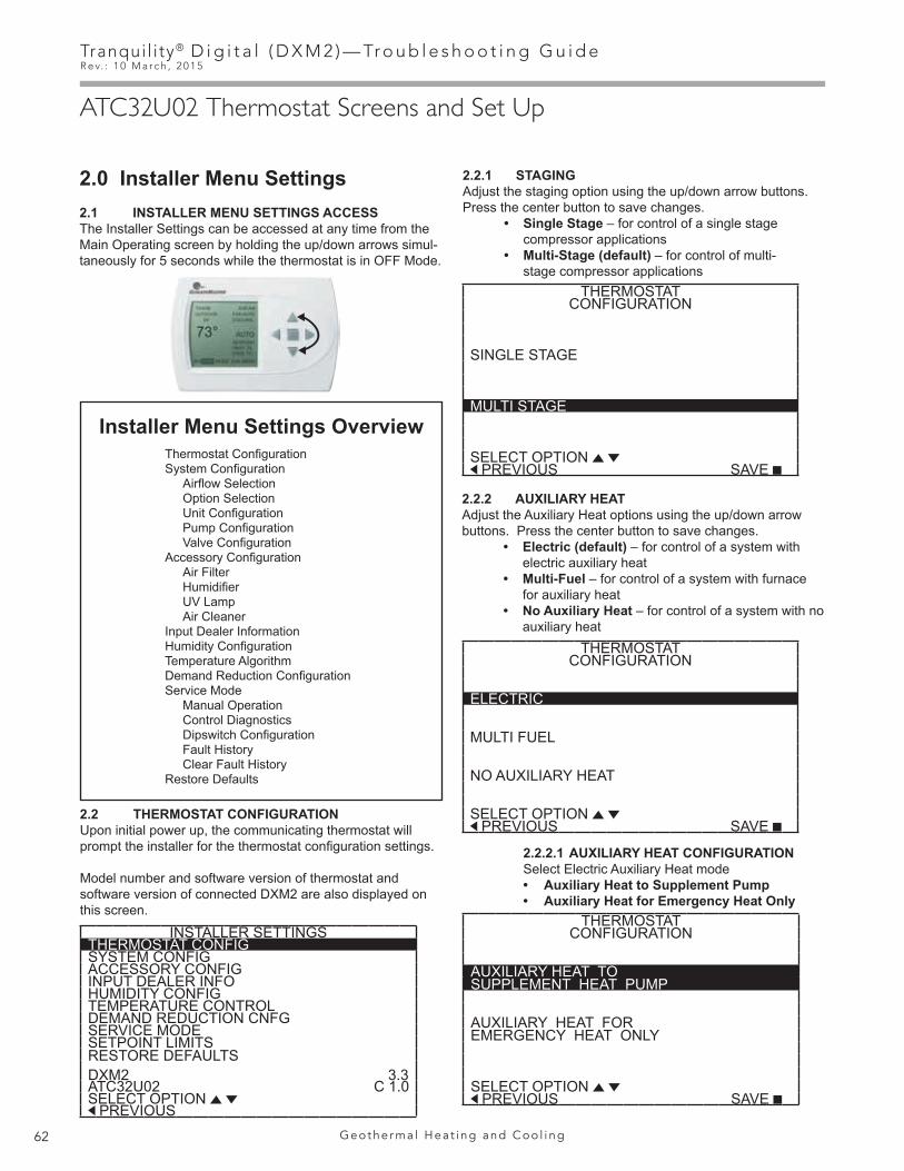
Tranqui l i ty® D i g i t a l ( D X M 2 ) — Tr o u b l e s h o o t i n g G u i d eR e v. : 1 0 M a r c h , 2 0 1 5
62 G e o t h e r m a l H e a t i n g a n d C o o l i n g
ATC32U02 Thermostat Screens and Set Up
2.0 Installer Menu Settings2.1 INSTALLER MENU SETTINGS ACCESSThe Installer Settings can be accessed at any time from the Main Operating screen by holding the up/down arrows simul-taneously for 5 seconds while the thermostat is in OFF Mode.
2.2 THERMOSTAT CONFIGURATIONUpon initial power up, the communicating thermostat will prompt the installer for the thermostat configuration settings.
Model number and software version of thermostat and software version of connected DXM2 are also displayed on this screen.
2.2.1 STAGINGAdjust the staging option using the up/down arrow buttons. Press the center button to save changes. • Single Stage – for control of a single stage compressor applications • Multi-Stage (default) – for control of multi- stage compressor applications
2.2.2 AUXILIARY HEATAdjust the Auxiliary Heat options using the up/down arrow buttons. Press the center button to save changes. • Electric (default) – for control of a system with electric auxiliary heat • Multi-Fuel – for control of a system with furnace for auxiliary heat • No Auxiliary Heat – for control of a system with no auxiliary heat
2.2.2.1 AUXILIARY HEAT CONFIGURATION Select Electric Auxiliary Heat mode
• Auxiliary Heat to Supplement Pump• Auxiliary Heat for Emergency Heat Only
Thermostat ConfigurationSystem Configuration Airflow Selection Option Selection Unit Configuration Pump Configuration Valve Configuration Accessory Configuration Air Filter Humidifier UV Lamp Air Cleaner Input Dealer InformationHumidity ConfigurationTemperature AlgorithmDemand Reduction ConfigurationService Mode Manual Operation Control Diagnostics Dipswitch Configuration Fault History Clear Fault HistoryRestore Defaults
Installer Menu Settings Overview
THERMOSTATCONFIGURATION
SINGLE STAGE
MULTI STAGE
SELECT OPTION PREVIOUS SAVE
THERMOSTATCONFIGURATION
ELECTRIC
MULTI FUEL
NO AUXILIARY HEAT
SELECT OPTION PREVIOUS SAVE
THERMOSTATCONFIGURATION
AUXILIARY HEAT TOSUPPLEMENT HEAT PUMP
AUXILIARY HEAT FOREMERGENCY HEAT ONLY
SELECT OPTION PREVIOUS SAVE
INSTALLER SETTINGSTHERMOSTAT CONFIGSYSTEM CONFIGACCESSORY CONFIGINPUT DEALER INFOHUMIDITY CONFIGTEMPERATURE CONTROLDEMAND REDUCTION CNFGSERVICE MODESETPOINT LIMITSRESTORE DEFAULTSDXM2 3.3ATC32U02 C 1.0SELECT OPTION PREVIOUS

63
Tranqui l i ty® D i g i t a l ( D X M 2 ) — Tr o u b l e s h o o t i n g G u i d eR e v. : 1 0 M a r c h , 2 0 1 5
w w w. c l i m a t e m a s t e r. c o m
ATC32U02 Thermostat Screens and Set Up
AIRFLOW SELECTION CFMHEAT STAGE 1 600HEAT STAGE 2 750 AUXILIARY HEAT 850EMERGENCY HEAT 850COOL STAGE 1 525COOL STAGE 2 700COOL DEHUMID 1 425COOL DEHUMID 2 550CONTINUOUS FAN 350HEAT OFF DELAY 60COOL OFF DELAY 30 PREVIOUS NEXT
SYSTEM CONFIGURATION
AIRFLOW SELECTION
OPTION SELECTION
UNIT CONFIG TE026
PUMP CONFIGURATION
SELECT OPTION PREVIOUS SAVE
INSTALLER SETTINGSTHERMOSTAT CONFIGSYSTEM CONFIGACCESSORY CONFIGINPUT DEALER INFOHUMIDITY CONFIGTEMPERATURE CONTROLDEMAND REDUCTION CNFGSERVICE MODESETPOINT LIMITSRESTORE DEFAULTSDXM2 3.3ATC32U02 C 1.0SELECT OPTION PREVIOUS
3.0 System Configuration
Use the System Configuration option on the start-up screen to adjust critical equipment settings.
The System Configuration information will be automatically obtained from each communicating control in the system.
Note 1: The Airflow Selection menu (section 3.1) will not be present if the connected communicating control system has no blower.
Note 2: The Pump Configuration menu (section 3.4) will not be present if the connected communicating control is configured for No Loop Configuration (OTHER).
Note 3: The Valve Configuration menu (section 3.5) will not be present if the connected communicating control is configured for No Loop Configuration (OTHER).
3.1 AIRFLOW SELECTIONAdjust the airflow settings for each system operating mode using the up/down arrow buttons. Press the center button to select each item.
• Airflow Settings (defaults stored in control) - valid range: obtained from control (in 25 CFM increments)
• Blower Off Delay (default 60 seconds) – valid range: 0 to 255 seconds (in 5 second increments)
NOTE 1: The Airflow Settings will only be present if the connected communicating control is configured for ECM blower.
NOTE 2: If multiple units are connected to one thermostat, refer to section 3.6 for unit selection.
3.2 OPTION SELECTIONThis option allows the configuration of heat pump options to be modified.
Adjust the Option settings using the up/down arrow buttons. Press the center button to select each item.
• Motorized Valve (defaults stored in control) – valid range: Off, On “On” delays compressor start until the valve is fully open.
NOTE: “Motorized Valve” used here refers to a two-position motorized water valve, not to be confused with the modulating motorized water valve found in the LOOP CONFIG.
• Compressor ASCD (Anti-Short Cycle Delay (default stored in control) – valid range: 5 to 8 (in 1 minute increments)
NOTE 1: The Compressor Anti-Short Cycle Delay setting provides equipment protection by forcing the compressor to wait a few minutes before restarting.
NOTE 2: If multiple units are connected to one thermostat, refer to section 3.6 for unit selection.

Tranqui l i ty® D i g i t a l ( D X M 2 ) — Tr o u b l e s h o o t i n g G u i d eR e v. : 1 0 M a r c h , 2 0 1 5
64 G e o t h e r m a l H e a t i n g a n d C o o l i n g
ATC32U02 Thermostat Screens and Set Up
3.3 UNIT CONFIGURATIONAdjust the Unit Configuration settings including Heat Pump Family, Heat Pump Size, Blower Type, and Loop Configuration using the up/down arrow buttons. Press the center button to select each item.
• Heat Pump Family (default stored in control) – valid range: TE, TY, TES, TEP, TRT, TSM
• Heat Pump Size (default stored in control) – valid range: depends on Heat Pump Family setting
• Blower Type (default stored in control) – valid range: NONE, PSC–2SPD, ECM, PSC–1SPD• Loop Config (default stored in control) – valid
range: Other, VS PUMP, MOD VALVE
Airflow, pump and valves can be configured from ‘System Configuration’ screen.
Select ‘VS PUMP’ when applying an internal variable speed flow controller with other flow controllers on a single loop in parallel.
NOTE: Refer to section 3.6.3 for multi-unit configuration instructions.
OPTION SELECTION
MOTORIZED VALVE OFF
COMPRESSOR ASCD 5
PREVIOUS NEXT
� CAUTION! �CAUTION! This is a Commercial option only and does not alter Residential unit operation.
UNIT CONFIGURATION
CURRENT CONFIG TE026
HEAT PUMP FAMILY TE
HEAT PUMP SIZE 026
BLOWER TYPE ECM
LOOP CONFIG VS PUMP
SELECT OPTION PREVIOUS SAVE
VARIABLE SPD INTERNALPUMP CONFIGURATION
LOOP OPTION PARALLEL
PUMP CONTROL DELTA T
HEATING DELTA T 7 FCOOLING DELTA T 10 F
MAXIMUM HEAT LWT 80 FMINIMUM COOL LWT 40 F
PREVIOUS SELECT
3.4 PUMP CONFIGURATIONvFlow™ vs internal flow control pump can be controlled either through temperature differential (Delta T) or can be set to specific speed (fixed; % of full speed for each heat and cool stage).
Can be configured for either single pumping or parallel pumping.
Configure temperature differentials at the thermostat for vFlow™ units with an internal flow control pump.
Adjust the Pump Configuration settings using the up/down arrow buttons. Press the center button to select each item. • Heating Delta T (default stored in control) – valid range: 4 to 12ºF (in 1ºF increments) • Cooling Delta T (default stored in control) – valid range: 9 to 20ºF (in 1ºF increments)
Maximum Heat LWT (valid range based on specific model; refer to model IOM). Minimum Cool LWT (valid range based on specific model; refer to model IOM).
NOTE: Refer to section 3.6.3 for multi-unit configuration instructions.
To control vs pump by fixed speed, select ‘Pump Control’, press , use down arrow to select ‘Fixed’, and press to save.
Default stored in control. Valid range: 15% - 90% (in 1% increments)Heating Stage 1 Cooling Stage 1Heating Stage 2 Cooling Stage 2
If Loop Option is set to ‘PARALLEL’, valid range changes to 50-90% (in 1% increments).

65
Tranqui l i ty® D i g i t a l ( D X M 2 ) — Tr o u b l e s h o o t i n g G u i d eR e v. : 1 0 M a r c h , 2 0 1 5
w w w. c l i m a t e m a s t e r. c o m
ATC32U02 Thermostat Screens and Set Up
VARIABLE SPD INTERNALPUMP CONFIGURATION
LOOP OPTION SINGLE
PUMP CONTROL FIXED
HEATING STAGE 1 60%COOLING STAGE 2 75%
COOLING STAGE 1 50%COOLING STAGE 2 70%
PREVIOUS SELECT
MODULATING VALVECONFIGURATION
OFF POSITION 0.0
VALVE CONTROL DELTA T
HEATING DELTA T 7 FCOOLING DELTA T 10 F
MAXIMUM HEAT LWT 80 FMINIMUM COOL LWT 40 F
PREVIOUS SELECT
3.5 VALVE CONFIGURATIONConfigure temperature differentials at the thermostat for vFlow™ units with a motorized modulating valve.
Adjust the Valve Configuration settings using the up/down arrow buttons. Press the center button to select each item. • Heating Delta T (default stored in control) – valid range: 4 to 12ºF (in 1ºF increments) • Cooling Delta T (default stored in control) – valid range: 9 to 20ºF (in 1ºF increments)
NOTE 1: Minimum and Maximum degree values are shown only when the control is configured with the appropriate values.
NOTE 2: Refer to section 3.6.3 for multi-unit configuration instructions.

Tranqui l i ty® D i g i t a l ( D X M 2 ) — Tr o u b l e s h o o t i n g G u i d eR e v. : 1 0 M a r c h , 2 0 1 5
66 G e o t h e r m a l H e a t i n g a n d C o o l i n g
ATC32U02 Thermostat Screens and Set Up
9.0 Service Mode
9.1 MANUAL OPERATIONManual Operation mode allows the service personnel to manually command operation for any of the thermostat outputs, blower speed, as well as pump speed or valve position to help troubleshoot specific components.
NOTE 1: The ECM Airflow adjustment will not be present if the connected communicating control (DXM2) is not configured for ECM (section 3.3).
NOTE 2: The Pump Speed adjustment will not be present if the connected communicating control (DXM2) is not configured for Pump (section 3.3).
NOTE 3: The Valve Position adjustment will not be present if the connected communicating control (DXM2) is configured for Valve (section 3.1).
NOTE 4: If multiple units are connected to one thermostat, refer to section 9.6
9.2 CONTROL DIAGNOSTICSControl Diagnostics mode allows the service personnel to view the status of all physical inputs, switches, temperature sensor readings, as well as the operational status of the pump at the thermostat.
Navigate between diagnostic screens using the left/right arrow buttons.
NOTE 1: The Pump Status will not be present if the connected communicating control (DXM2) is not configured for Pump (section 3.3).
NOTE 2: If multiple units are connected to one thermostat, refer to section 9.6.
SERVICE MODE
MANUAL OPERATION
CONTROL DIAGNOSTICS
DIPSWITCH CONFIG
FAULT HISTORY
CLEAR FAULT HISTORY
SELECT OPTION PREVIOUS SELECT
MANUAL OPERATING MODE
Y1 COMM OUTPUT OFFY2 COMM OUTPUT OFFW COMM OUTPUT OFFO COMM OUTPUT OFFG COMM OUTPUT OFFH COMM OUTPUT OFFDH COMM OUTPUT OFFECM AIRFLOW 0PUMP SPEED 0%TEST MODE OFF
SELECT OPTION PREVIOUS SELECT
CONTROL DIAGNOSTICS - 2HP SWITCH CLLOC SWITCH CLY1 PHYSICAL INPUT ONY2 PHYSICAL INPUT OFFW PHYSICAL INPUT OFFO PHYSICAL INPUT ONG PHYSICAL INPUT ONH PHYSICAL INPUT OFFEMERG SHUTDOWN OFFNIGHT SETBACK OFFOVR INPUT OFFCONTROL VOLTAGE 26.4
PREVIOUS
CONTROL DIAGNOSTICS - 1LT1 TEMP 38.1LT2 TEMP 79.9COMP DISCHARGE 157.7ENTERING WATER 78.5LEAVING WATER 73.3HOT WATER EWT 121.5LEAVING AIR 75.1LOOP PUMP SPD 60%LOOP PUMP WATTS 140LOOP FLOW GPM 7.4ECM BLOWER RPM 550ECM TARGET CFM 800ECM BLOWER STATIC 0.5 PREVIOUS NEXT

67
Tranqui l i ty® D i g i t a l ( D X M 2 ) — Tr o u b l e s h o o t i n g G u i d eR e v. : 1 0 M a r c h , 2 0 1 5
w w w. c l i m a t e m a s t e r. c o m
ATC32U02 Thermostat Screens and Set Up
9.3 DIPSWITCH CONFIGURATIONDipswitch Configuration mode allows the service personnel to view the status of all dipswitch settings for the connected communicating control (DXM2/AXM) at the thermostat.
Navigate between configuration screens using the left/right arrow buttons. NOTE 1: The unit control dipswitch settings cannot be changed from the thermostat.
NOTE 2: If multiple units are connected to one thermostat, refer to section 9.6.
9.4 FAULT HISTORYFault History mode displays the five most recent stored fault codes for the connected communicating control (DXM2).
Navigate between control fault codes using the up/down arrow buttons. Press the center button to view more information about the highlighted fault code.
NOTE: If multiple units are connected to one thermostat, refer to section 9.7.
9.4.1 Temperature ConditionsDisplays detailed temperature readings that were recorded at the time the fault occurred.
NOTE: If multiple units are connected to one thermostat, refer to section 9.6.
CONTROL CONFIGURATIONDIPSWITCH S1
1 ON UPS ENABLED2 ON DUAL COMP STG 13 ON HEAT PUMP TSTAT4 ON RV O THERMOSTAT5 ON DEHUMID OFF6 ON EH2 AUX HEAT7 ON BOILERLESS8 ON SEE DXM2 AOM
PREVIOUS NEXT
CONTROL CONFIGURATIONDIPSWITCH S2
1 ON \ ACCESSORY 12 ON ACCESSORY 23 ON/
4 ON \ ACCESSORY 25 ON ACTIVE W/ COMP6 ON /
7 ON H DEHUM INPUT8 ON FACTORY SETTING PREVIOUS NEXT
CONTROL CONFIGURATIONDIPSWITCH S3
1 ON FACTORY SETTING2 OFF HWG TEST OFF3 OFF HWG SP 1254 OFF HWG DISABLED
JW3 LT1 SETTING WELL
PREVIOUS
TT038 SN - - - - - 0 1 2 3LAST 5 FAULTS
LT1 LOW WATER TEMP
NO FAULT
NO FAULT
NO FAULT
NO FAULT
NEXT PREVIOUS SELECT
FAULT TEMPERATURE CONDITIONSLT1 LOW WATER TEMP
HEAT 1 11:11 AM 11/14LT1 TEMP 28.1LT2 TEMP 97.3HOT WATER EWT 121.5COMP DISCHARGE 157.7LEAVING AIR 92.7LEAVING WATER 34.9ENTERING WATER 42.1CONTROL VOLTAGE 26.4 PREVIOUS
FAULT CONDITION MENU
LT1 LOW WATER TEMPHEAT 1 11:11 AM 11/14
FAULT TEMP CONDITIONS
FAULT FLOW CONDITIONS
FAULT I/O CONDITIONS
FAULT CONFIG COND
FAULT POSSIBLE CAUSES PREVIOUS SELECT

Tranqui l i ty® D i g i t a l ( D X M 2 ) — Tr o u b l e s h o o t i n g G u i d eR e v. : 1 0 M a r c h , 2 0 1 5
68 G e o t h e r m a l H e a t i n g a n d C o o l i n g
ATC32U02 Thermostat Screens and Set Up
9.4.2 Flow ConditionsDisplays detailed blower and pump speed / valve position readings that were recorded at the time the fault occurred.
NOTE: If multiple units are connected to one thermostat, refer to section 9.7.
9.4.3 Input/Output ConditionsDisplays the status of all physical and communicated inputs, switches, and control outputs that were recorded at the time the fault occurred.
NOTE: If multiple units are connected to one thermostat, refer to section 9.7.
9.4.4 Configuration ConditionsDisplays the status of all dipswitch settings that were recorded at the time the fault occurred.
NOTE: If multiple units are connected to one thermostat, refer to section 9.7.
9.4.5 Possible Causes Possible causes as to why the fault occurred
NOTE: If multiple units are connected to one thermostat, refer to section 9.7.
9.5 CLEAR FAULT HISTORYClear Fault History will clear all fault codes stored in the thermostat as well as the fault history in any connected communicating controls (DXM2/AXM).
FAULT FLOW CONDITIONSLT1 LOW WATER TEMPHEAT 1 11:11 AM 11/14ECM TARGET CFM 800ECM BLOWER RPM 550FLOW RATE GPM 6.5PUMP SPEED 60%PUMP WATTS 140LOOP CONFIG VS PUMP PREVIOUS SINGLE
FAULT I / O CONDITIONSLT1 LOW WATER TEMPHEAT 1 11:11 AM 11/14
TSTAT SAFETY OUTPTCONV COMM HPS
Y1 Y1 LOC CCY2 Y2 CO RVW W ACC1O O OUTPT ACC2G G FAN AL1H H HWG EH1
OVR DH PUMP EH2
PREVIOUS
FAULT CONFG CONDITIONS
LT1 LOW WATER TEMPHEAT 1 11:11 AM 11/14
S1 S2 S31 ON 1 ON 1 ON2 ON 2 ON 2 OFF3 ON 3 ON 3 OFF4 ON 4 ON 4 OFF5 ON 5 ON6 ON 6 ON LT1 WELL7 ON 7 ON LT2 WELL8 ON 8 ON PREVIOUS
POSSIBLE FAULT CAUSESLOW WATER COIL TEMP
LOW WATER TEMP - HTGLOW WATER FLOW - HTGLOW REFRIG CHARGE - HTGINCORRECT LT1 SETTINGBAD LT1 THERMISTOR PREVIOUS

69
Tranqui l i ty® D i g i t a l ( D X M 2 ) — Tr o u b l e s h o o t i n g G u i d eR e v. : 1 0 M a r c h , 2 0 1 5
w w w. c l i m a t e m a s t e r. c o m
Notes:

Tranqui l i ty® D i g i t a l ( D X M 2 ) — Tr o u b l e s h o o t i n g G u i d eR e v. : 1 0 M a r c h , 2 0 1 5
70 G e o t h e r m a l H e a t i n g a n d C o o l i n g

71
Tranqui l i ty® D i g i t a l ( D X M 2 ) — Tr o u b l e s h o o t i n g G u i d eR e v. : 1 0 M a r c h , 2 0 1 5
w w w. c l i m a t e m a s t e r. c o m

Tranqui l i ty® D i g i t a l ( D X M 2 ) — Tr o u b l e s h o o t i n g G u i d eR e v. : 1 0 M a r c h , 2 0 1 5
72 G e o t h e r m a l H e a t i n g a n d C o o l i n g
R
MA
NU
FAC
TUR
ER
CERTIFIED TO ARI AS COMPLY
ING
WIT
H
ISOSTANDARD 13256-1
HEAT PUMPS
WAT
ERTO
AIR BRINETOAIR
97B0601N01
ClimateMaster works continually to improve its products. As a result, the design and specifications of each product at the time for order may be changed without notice and may not be as described herein. Please contact ClimateMaster’s Customer Service Department at 1-405-745-6000 for specific information on the current design and specifications. Statements and other information contained herein are not express warran-ties and do not form the basis of any bargain between the parties, but are merely ClimateMaster’s opinion or commendation of its products.The management system governing the manufacture of ClimateMaster’s products is ISO 9001:2008 certified. © ClimateMaster, Inc. 2013
*97B0601N01*
7300 S.W. 44th StreetOklahoma City, OK 73179
Phone: 405-745-6000Fax: 405-745-6058climatemaster.com
Rev.: 10 March, 2015
ISO 9001:2008Certified
Quality: First & Always
Revision History
Date Page # Description10 March, 2015 Various Content Updated
3 April, 2014 Various Content Updated15 Jan., 2014 36 ‘Verifying DC Voltage on DXM2 Board for Mod Valve Check’ Diagram Corrected6 Sept., 2013 All First Printed