training program dc products - clutches and brakes program dc products - clutches and brakes ......
TRANSCRIPT
®Industrial Clutches and Brakes
Training ProgramDC Products - Clutches and Brakes
Table of Contents
Section Title Page
Introduction . . . . . . . . . . . . . . . . . . . . . . . . . . . . . . . . . . . . . . . . . . . . . . . . . . . . . 1
1 Fundamental Concepts . . . . . . . . . . . . . . . . . . . . . . . . . . . . . . . . . . . . . . . . . . . 2
2 Purpose of Clutches and Brakes . . . . . . . . . . . . . . . . . . . . . . . . . . . . . . . . . . . . 3-4
3 Types of Clutches and Brakes . . . . . . . . . . . . . . . . . . . . . . . . . . . . . . . . . . . . . . 5-7
4 Principles of Friction Braking and Clutching . . . . . . . . . . . . . . . . . . . . . . . . . . . 8-9
5 Principles of Electrically Actuated Friction Clutches and Brakes . . . . . . . . . . . .10-13
6 Basic Rectifier/Power Supply Controls . . . . . . . . . . . . . . . . . . . . . . . . . . . . . . . .14-15
7 Two Step Selection Procedure . . . . . . . . . . . . . . . . . . . . . . . . . . . . . . . . . . . . . .16-17
8 Engineering Fundamentals and Detailed Selection Procedure . . . . . . . . . . . . .18-26
Multiplication of Torque . . . . . . . . . . . . . . . . . . . . . . . . . . . . . . . . . . . . . . . . . . 21
Inertia . . . . . . . . . . . . . . . . . . . . . . . . . . . . . . . . . . . . . . . . . . . . . . . . . . . . . . .21-22
Calculation of Inertia . . . . . . . . . . . . . . . . . . . . . . . . . . . . . . . . . . . . . . . . . . . .22-23
Reflected Inertia . . . . . . . . . . . . . . . . . . . . . . . . . . . . . . . . . . . . . . . . . . . . . . .23-25
Dynamic Torque . . . . . . . . . . . . . . . . . . . . . . . . . . . . . . . . . . . . . . . . . . . . . . . 25
Thermal Capacity . . . . . . . . . . . . . . . . . . . . . . . . . . . . . . . . . . . . . . . . . . . . . .25-26
9 Summary . . . . . . . . . . . . . . . . . . . . . . . . . . . . . . . . . . . . . . . . . . . . . . . . . . . . . . 27
10 Typical Stearns DC Product Applications . . . . . . . . . . . . . . . . . . . . . . . . . . . . . . 28
11 Appendix . . . . . . . . . . . . . . . . . . . . . . . . . . . . . . . . . . . . . . . . . . . . . . . . . . . . . . .29-31
12 Other Products . . . . . . . . . . . . . . . . . . . . . . . . . . . . . . . . . . . . . . . . . . . . . . . . . .32-34
IntroductionA power transmission system converts energy into
useful work.In a typical system, an electric motor is used to convert
electrical energy into rotating mechanical energy. Mechanical energy can be transmitted by a system of mechanical components to perform some usefulfunction or work.
This system, composed of mechanical componentsmay include one or more of the following:
• Shafts • Shaft couplings• Bearings • Pulleys and belts• Cams • Clutches and brakes• Levers • Etc.
Our intent in this program or guide is to discuss clutches and brakes which, when used in a power transmission system, can control the flow ortransmission of mechanical energy.
There are many different types of clutches and brakes.The Stearns products discussed in this guide will narrowdown to electromechanical clutches and brakes which fallunder our general heading of DC products.
Catalog Data, Installation, and Parts Sheets for theseproducts can be found at www.rexnord.com/brakes.html.
1
1. Fundamental Concepts
We say that objects possess energy when they can dowork. And that power is the rate at which work isperformed or that energy is used. In the English or US customary engineering system, the units of power are thehorsepower (hp) and the kilowatt (kw).
A) Power = work
Work is defined as the product of an incremental displacement and of the force vector in the direction of the displacement. When a force of one pound acts through adistance of one foot, than 1 ft-lb of work is done.
B) Work = distance x forceExample units = foot-pound
= inch-ounce= inch-pound
Power is defined as:
C) Power = distance x force
The next concept is that of torque. If a force is applied to alever which is free to pivot around one fixed point, thelever, unless restrained, will rotate about the pivot point.The motive action for this rotation, termed torque, isdefined as the product of force and the perpendicular dis-tance from the pivot to the force vector.
D) Torque = force x distanceExample units = pound-foot
= ounce-inch= pound-inch
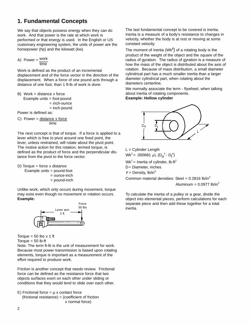
Unlike work, which only occurs during movement, torquemay exist even though no movement or rotation occurs.Example:
Torque = 50 lbs x 1 ftTorque = 50 lb-ftNote: The term ft-lb is the unit of measurement for work.Because most power transmission is based upon rotatingelements, torque is important as a measurement of theeffort required to produce work.
Friction is another concept that needs review. Frictionalforce can be defined as the resistance force that twoobjects surfaces exert on each other under sliding or conditions that they would tend to slide over each other.
E) Frictional force = µ x contact force(frictional resistance) = (coefficient of friction
x normal force)
The last fundamental concept to be covered is inertia.Inertia is a measure of a body’s resistance to changes invelocity, whether the body is at rest or moving at someconstant velocity.
The moment of inertia (Wk2) of a rotating body is theproduct of the weight of the object and the square of theradius of gyration. The radius of gyration is a measure ofhow the mass of the object is distributed about the axis ofrotation. Because of mass distribution, a small diametercylindrical part has a much smaller inertia than a largerdiameter cylindrical part, when rotating about the diameters centerline.We normally associate the term - flywheel, when talkingabout inertia of rotating components.Example: Hollow cylinder
L = Cylinder LengthWk2 = .000681 L (Do
4 - Dl4)
Wk2 = Inertia of cylinder, lb-ft2
D= Diameter, inches? = Density, lb/in3
Common material densities: Steel = 0.2816 lb/in3
Aluminum = 0.0977 lb/in3
To calculate the inertia of a pulley or a gear, divide theobject into elemental pieces, perform calculations for eachseparate piece and then add these together for a totalinertia.
time
time
2
Lever arm1 ft
Force50 lbs
A clutch or brake in a power transmission system functionsas a door or gate. These components direct the flow ofrotational energy to start or/and stop work. Just as a lightswitch is used to turn an electric light on and off; clutchesand brakes are used to turn power on and off to a load.The following examples and diagrams illustrate whereclutches and brakes can be used and why thesecomponents are advantageous.
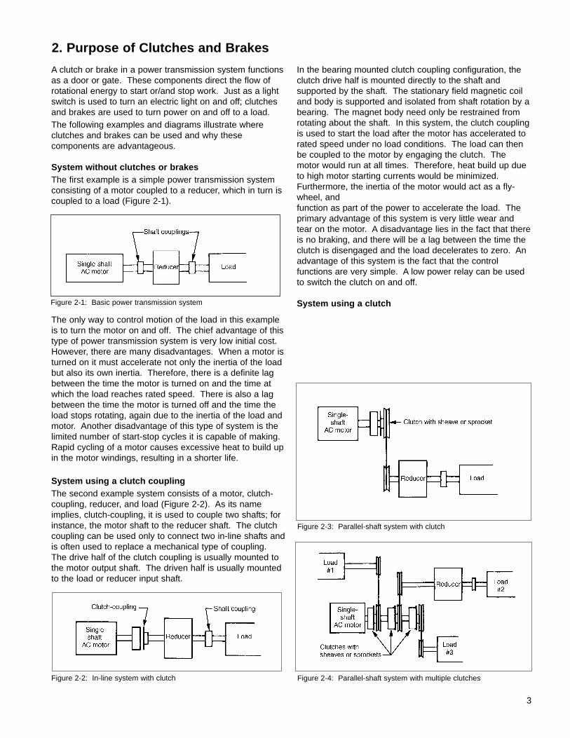
System without clutches or brakesThe first example is a simple power transmission systemconsisting of a motor coupled to a reducer, which in turn iscoupled to a load (Figure 2-1).
The only way to control motion of the load in this exampleis to turn the motor on and off. The chief advantage of thistype of power transmission system is very low initial cost.However, there are many disadvantages. When a motor isturned on it must accelerate not only the inertia of the loadbut also its own inertia. Therefore, there is a definite lagbetween the time the motor is turned on and the time atwhich the load reaches rated speed. There is also a lagbetween the time the motor is turned off and the time theload stops rotating, again due to the inertia of the load andmotor. Another disadvantage of this type of system is thelimited number of start-stop cycles it is capable of making.Rapid cycling of a motor causes excessive heat to build upin the motor windings, resulting in a shorter life.
System using a clutch couplingThe second example system consists of a motor, clutch-coupling, reducer, and load (Figure 2-2). As its nameimplies, clutch-coupling, it is used to couple two shafts; forinstance, the motor shaft to the reducer shaft. The clutchcoupling can be used only to connect two in-line shafts andis often used to replace a mechanical type of coupling.The drive half of the clutch coupling is usually mounted tothe motor output shaft. The driven half is usually mountedto the load or reducer input shaft.
In the bearing mounted clutch coupling configuration, theclutch drive half is mounted directly to the shaft and supported by the shaft. The stationary field magnetic coiland body is supported and isolated from shaft rotation by abearing. The magnet body need only be restrained fromrotating about the shaft. In this system, the clutch couplingis used to start the load after the motor has accelerated torated speed under no load conditions. The load can thenbe coupled to the motor by engaging the clutch. Themotor would run at all times. Therefore, heat build up dueto high motor starting currents would be minimized.Furthermore, the inertia of the motor would act as a fly-wheel, and function as part of the power to accelerate the load. The primary advantage of this system is very little wear andtear on the motor. A disadvantage lies in the fact that thereis no braking, and there will be a lag between the time theclutch is disengaged and the load decelerates to zero. Anadvantage of this system is the fact that the control functions are very simple. A low power relay can be usedto switch the clutch on and off.
System using a clutch
2. Purpose of Clutches and Brakes
Figure 2-1: Basic power transmission system
Figure 2-2: In-line system with clutch
Figure 2-3: Parallel-shaft system with clutch
Figure 2-4: Parallel-shaft system with multiple clutches
3
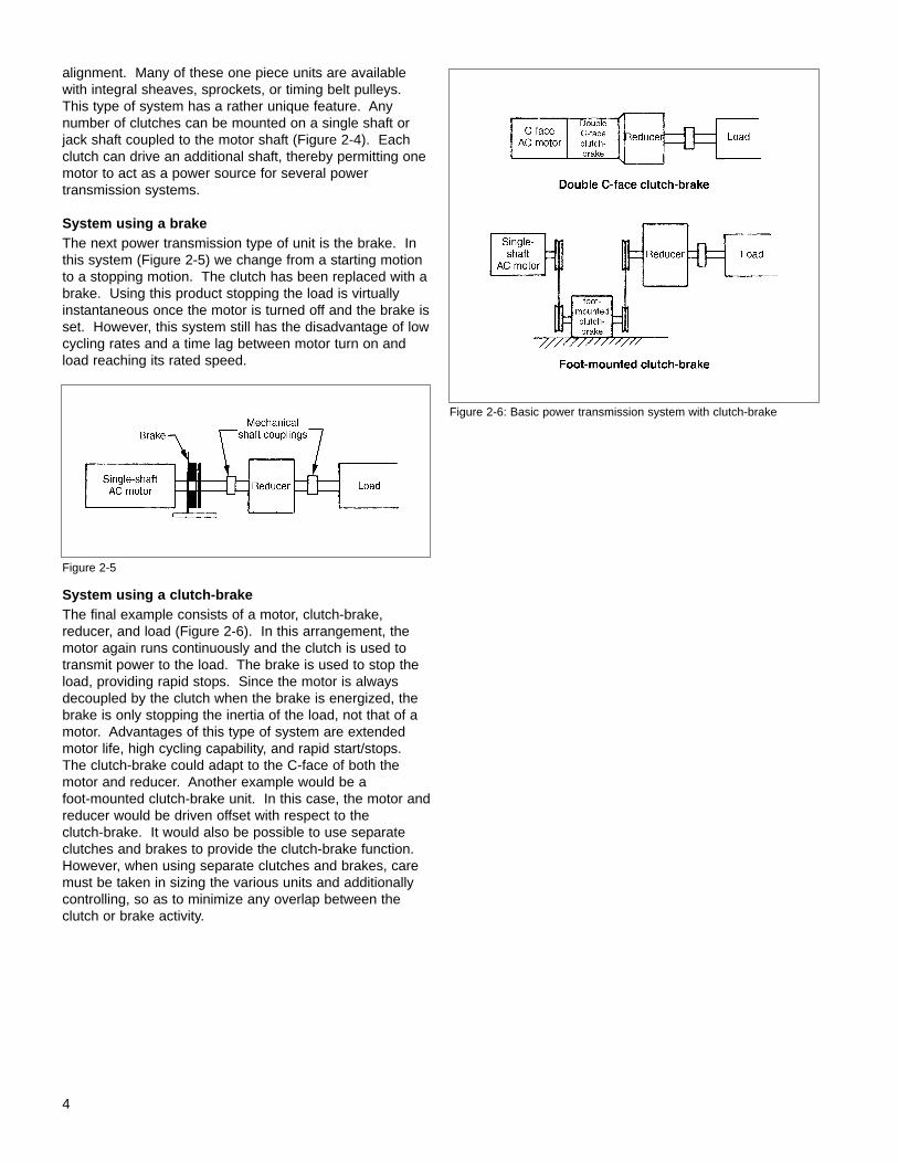
alignment. Many of these one piece units are availablewith integral sheaves, sprockets, or timing belt pulleys. This type of system has a rather unique feature. Any number of clutches can be mounted on a single shaft orjack shaft coupled to the motor shaft (Figure 2-4). Eachclutch can drive an additional shaft, thereby permitting onemotor to act as a power source for several power transmission systems.
System using a brakeThe next power transmission type of unit is the brake. Inthis system (Figure 2-5) we change from a starting motionto a stopping motion. The clutch has been replaced with abrake. Using this product stopping the load is virtuallyinstantaneous once the motor is turned off and the brake isset. However, this system still has the disadvantage of lowcycling rates and a time lag between motor turn on andload reaching its rated speed.
System using a clutch-brakeThe final example consists of a motor, clutch-brake,reducer, and load (Figure 2-6). In this arrangement, themotor again runs continuously and the clutch is used totransmit power to the load. The brake is used to stop theload, providing rapid stops. Since the motor is alwaysdecoupled by the clutch when the brake is energized, thebrake is only stopping the inertia of the load, not that of amotor. Advantages of this type of system are extendedmotor life, high cycling capability, and rapid start/stops.The clutch-brake could adapt to the C-face of both themotor and reducer. Another example would be a foot-mounted clutch-brake unit. In this case, the motor andreducer would be driven offset with respect to the clutch-brake. It would also be possible to use separateclutches and brakes to provide the clutch-brake function.However, when using separate clutches and brakes, caremust be taken in sizing the various units and additionallycontrolling, so as to minimize any overlap between theclutch or brake activity.
4
Figure 2-5
Figure 2-6: Basic power transmission system with clutch-brake
For purposes of discussion the following examples arebrakes, but clutch systems can be designed around thesame operation principles.
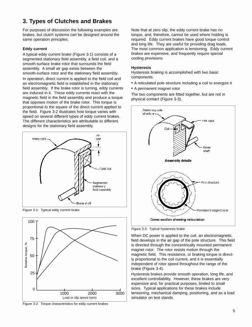
Eddy currentA typical eddy current brake (Figure 3-1) consists of a segmented stationary field assembly, a field coil, and asmooth-surface brake rotor that surrounds the field assembly. A small air gap exists between the smooth-surface rotor and the stationary field assembly.In operation, direct current is applied to the field coil andan electromagnetic field is established in the stationaryfield assembly. If the brake rotor is turning, eddy currentsare induced in it. These eddy currents react with the magnetic field in the field assembly and produce a torquethat opposes motion of the brake rotor. This torque is proportional to the square of the direct current applied tothe field. Figure 3-2 illustrates how torque varies withspeed on several different types of eddy current brakes.The different characteristics are attributable to differentdesigns for the stationary field assembly.
Note that at zero slip, the eddy current brake has notorque, and, therefore, cannot be used where holding isrequired. Eddy current brakes have good torque controland long life. They are useful for providing drag loads.The most common application is tensioning. Eddy currentbrakes are expensive, and frequently require specialcooling provisions.
HysteresisHysteresis braking is accomplished with two basiccomponents.
• A reticulated pole structure including a coil to energize it• A permanent magnet rotor
The two components are fitted together, but are not inphysical contact (Figure 3-3).
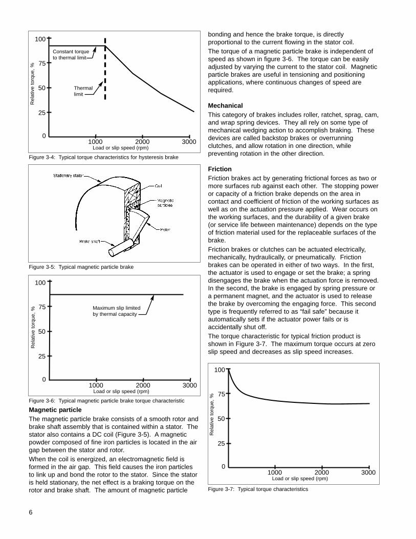
When DC power is applied to the coil, an electromagneticfield develops in the air gap of the pole structure. This fieldis directed through the concentrically mounted permanentmagnet rotor. The rotor resists motion through the magnetic field. This resistance, or braking torque is direct-ly proportional to the coil current, and it is essentially independent of rotor speed throughout the range of thebrake (Figure 3-4).Hysteresis brakes provide smooth operation, long life, andexcellent controllability. However, these brakes are veryexpensive and, for practical purposes, limited to smallsizes. Typical applications for these brakes include tensioning, mechanical damping, positioning, and as a loadsimulator on test stands.
3. Types of Clutches and Brakes
Figure 3-1: Typical eddy current brake
Figure 3-2: Torque characteristics for eddy current brakes
Figure 3-3: Typical hysteresis brake
5
100
75
50
25
01000 2000 3000
Rel
ativ
e to
rque
, %
Load or slip speed (rpm)
6
Magnetic particleThe magnetic particle brake consists of a smooth rotor andbrake shaft assembly that is contained within a stator. Thestator also contains a DC coil (Figure 3-5). A magneticpowder composed of fine iron particles is located in the airgap between the stator and rotor.When the coil is energized, an electromagnetic field isformed in the air gap. This field causes the iron particlesto link up and bond the rotor to the stator. Since the statoris held stationary, the net effect is a braking torque on therotor and brake shaft. The amount of magnetic particle
bonding and hence the brake torque, is directlyproportional to the current flowing in the stator coil.The torque of a magnetic particle brake is independent ofspeed as shown in figure 3-6. The torque can be easilyadjusted by varying the current to the stator coil. Magneticparticle brakes are useful in tensioning and positioningapplications, where continuous changes of speed arerequired.
MechanicalThis category of brakes includes roller, ratchet, sprag, cam,and wrap spring devices. They all rely on some type ofmechanical wedging action to accomplish braking. Thesedevices are called backstop brakes or overrunning clutches, and allow rotation in one direction, while preventing rotation in the other direction.
FrictionFriction brakes act by generating frictional forces as two ormore surfaces rub against each other. The stopping poweror capacity of a friction brake depends on the area in contact and coefficient of friction of the working surfaces aswell as on the actuation pressure applied. Wear occurs onthe working surfaces, and the durability of a given brake(or service life between maintenance) depends on the typeof friction material used for the replaceable surfaces of thebrake.Friction brakes or clutches can be actuated electrically,mechanically, hydraulically, or pneumatically. Frictionbrakes can be operated in either of two ways. In the first,the actuator is used to engage or set the brake; a springdisengages the brake when the actuation force is removed.In the second, the brake is engaged by spring pressure ora permanent magnet, and the actuator is used to releasethe brake by overcoming the engaging force. This secondtype is frequently referred to as “fail safe” because it automatically sets if the actuator power fails or is accidentally shut off.The torque characteristic for typical friction product isshown in Figure 3-7. The maximum torque occurs at zeroslip speed and decreases as slip speed increases.
Figure 3-4: Typical torque characteristics for hysteresis brake
Figure 3-5: Typical magnetic particle brake
Figure 3-7: Typical torque characteristics
100
75
50
25
01000 2000 3000
Rel
ativ
e to
rque
, %
Load or slip speed (rpm)
100
75
50
25
01000 2000 3000
Rel
ativ
e to
rque
, %
Load or slip speed (rpm)
100
75
50
25
01000 2000 3000
Rel
ativ
e to
rque
, %
Load or slip speed (rpm)
Figure 3-6: Typical magnetic particle brake torque characteristic
Thermallimit
Constant torqueto thermal limit
Maximum slip limitedby thermal capacity
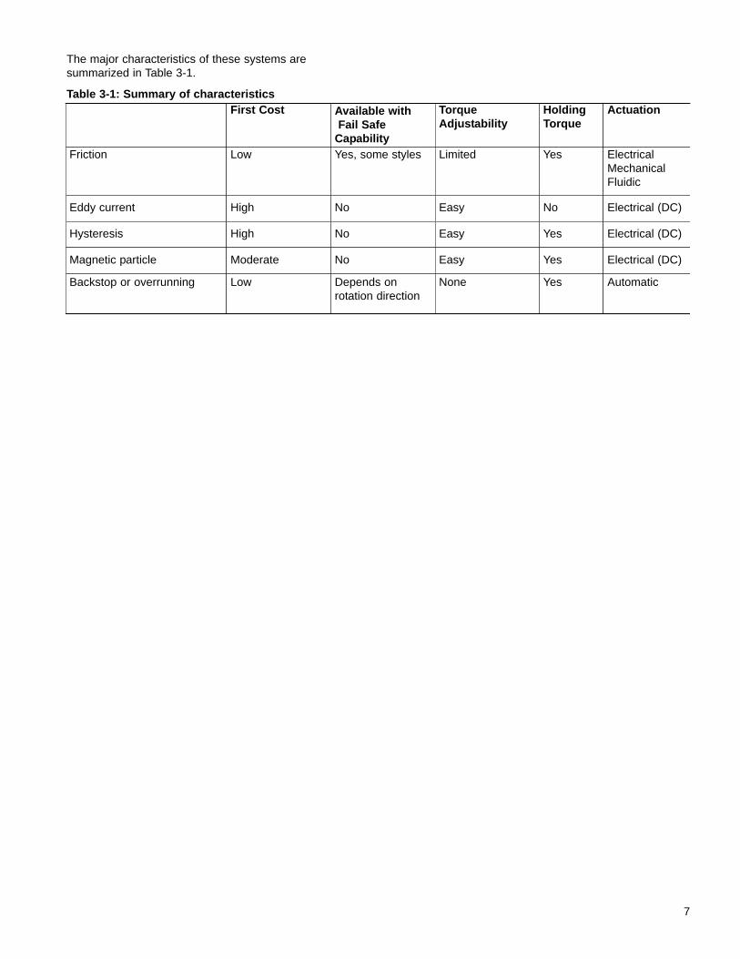
The major characteristics of these systems are summarized in Table 3-1.
Table 3-1: Summary of characteristics
7
First Cost Available withFail Safe
Capability
TorqueAdjustability
HoldingTorque
Actuation
Friction Low Yes, some styles Limited Yes ElectricalMechanicalFluidic
Eddy current High No Easy No Electrical (DC)
Hysteresis High No Easy Yes Electrical (DC)
Magnetic particle Moderate No Easy Yes Electrical (DC)
Backstop or overrunning Low Depends onrotation direction
None Yes Automatic
Friction products are simple, low cost, flexible, and reliable.They are the most practical products for use in cyclingapplications. When released, friction products offerminimal residual drag.Friction products are available in a variety of styles, andcan be operated with several different types of actuators.All styles, however, have two common characteristics:
• Torque • Thermal capacity
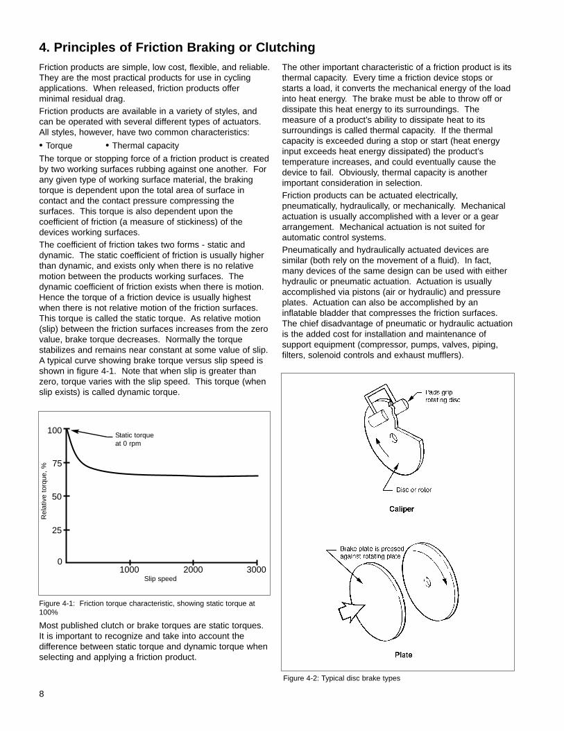
The torque or stopping force of a friction product is createdby two working surfaces rubbing against one another. Forany given type of working surface material, the brakingtorque is dependent upon the total area of surface incontact and the contact pressure compressing the surfaces. This torque is also dependent upon the coefficient of friction (a measure of stickiness) of thedevices working surfaces.The coefficient of friction takes two forms - static anddynamic. The static coefficient of friction is usually higherthan dynamic, and exists only when there is no relativemotion between the products working surfaces. Thedynamic coefficient of friction exists when there is motion.Hence the torque of a friction device is usually highestwhen there is not relative motion of the friction surfaces.This torque is called the static torque. As relative motion(slip) between the friction surfaces increases from the zerovalue, brake torque decreases. Normally the torque stabilizes and remains near constant at some value of slip.A typical curve showing brake torque versus slip speed isshown in figure 4-1. Note that when slip is greater thanzero, torque varies with the slip speed. This torque (whenslip exists) is called dynamic torque.
Most published clutch or brake torques are static torques.It is important to recognize and take into account thedifference between static torque and dynamic torque whenselecting and applying a friction product.
The other important characteristic of a friction product is itsthermal capacity. Every time a friction device stops orstarts a load, it converts the mechanical energy of the loadinto heat energy. The brake must be able to throw off ordissipate this heat energy to its surroundings. The measure of a product’s ability to dissipate heat to its surroundings is called thermal capacity. If the thermalcapacity is exceeded during a stop or start (heat energyinput exceeds heat energy dissipated) the product’s temperature increases, and could eventually cause thedevice to fail. Obviously, thermal capacity is another important consideration in selection.Friction products can be actuated electrically, pneumatically, hydraulically, or mechanically. Mechanicalactuation is usually accomplished with a lever or a geararrangement. Mechanical actuation is not suited for automatic control systems.Pneumatically and hydraulically actuated devices are similar (both rely on the movement of a fluid). In fact,many devices of the same design can be used with eitherhydraulic or pneumatic actuation. Actuation is usuallyaccomplished via pistons (air or hydraulic) and pressureplates. Actuation can also be accomplished by aninflatable bladder that compresses the friction surfaces.The chief disadvantage of pneumatic or hydraulic actuationis the added cost for installation and maintenance of support equipment (compressor, pumps, valves, piping,filters, solenoid controls and exhaust mufflers).
8
4. Principles of Friction Braking or Clutching
Figure 4-1: Friction torque characteristic, showing static torque at100%
Figure 4-2: Typical disc brake types
100
75
50
25
01000 2000 3000
Rel
ativ
e to
rque
, %
Slip speed
Static torqueat 0 rpm

Electrical actuation allows extremely fast reaction andcycle rates. It is also well suited for remote and automaticcontrol. Electric actuation allows a great deal of controlflexibility, and permits direct interface with computerizedcontrollers.Stearns Division manufactures three basic friction productlines:1. Spring-set brakes — plate types that are spring set and
electrically released.2. Electrically engaged products — plate disc (single
surface) type that are electrically set. These are directacting and DC actuated.
3. Heavy duty products — plate disc type that are springset and electrically released or electrically engaged.These products are direct acting and DC actuated.
Figure 4-3: Two modes of friction operation
9
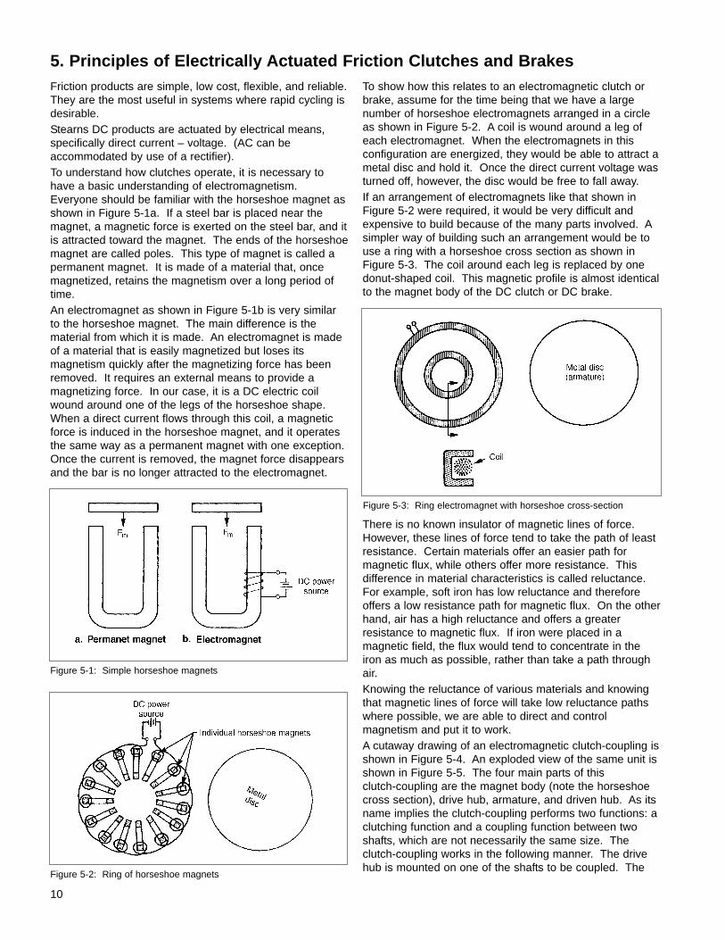
Friction products are simple, low cost, flexible, and reliable.They are the most useful in systems where rapid cycling isdesirable.Stearns DC products are actuated by electrical means,specifically direct current – voltage. (AC can be accommodated by use of a rectifier).To understand how clutches operate, it is necessary tohave a basic understanding of electromagnetism.Everyone should be familiar with the horseshoe magnet asshown in Figure 5-1a. If a steel bar is placed near themagnet, a magnetic force is exerted on the steel bar, and itis attracted toward the magnet. The ends of the horseshoemagnet are called poles. This type of magnet is called apermanent magnet. It is made of a material that, oncemagnetized, retains the magnetism over a long period oftime.An electromagnet as shown in Figure 5-1b is very similarto the horseshoe magnet. The main difference is the material from which it is made. An electromagnet is madeof a material that is easily magnetized but loses its magnetism quickly after the magnetizing force has beenremoved. It requires an external means to provide a magnetizing force. In our case, it is a DC electric coilwound around one of the legs of the horseshoe shape.When a direct current flows through this coil, a magneticforce is induced in the horseshoe magnet, and it operatesthe same way as a permanent magnet with one exception.Once the current is removed, the magnet force disappearsand the bar is no longer attracted to the electromagnet.
To show how this relates to an electromagnetic clutch orbrake, assume for the time being that we have a largenumber of horseshoe electromagnets arranged in a circleas shown in Figure 5-2. A coil is wound around a leg ofeach electromagnet. When the electromagnets in this configuration are energized, they would be able to attract ametal disc and hold it. Once the direct current voltage wasturned off, however, the disc would be free to fall away.If an arrangement of electromagnets like that shown inFigure 5-2 were required, it would be very difficult andexpensive to build because of the many parts involved. Asimpler way of building such an arrangement would be touse a ring with a horseshoe cross section as shown inFigure 5-3. The coil around each leg is replaced by one donut-shaped coil. This magnetic profile is almost identicalto the magnet body of the DC clutch or DC brake.
There is no known insulator of magnetic lines of force.However, these lines of force tend to take the path of leastresistance. Certain materials offer an easier path for magnetic flux, while others offer more resistance. This difference in material characteristics is called reluctance.For example, soft iron has low reluctance and thereforeoffers a low resistance path for magnetic flux. On the otherhand, air has a high reluctance and offers a greater resistance to magnetic flux. If iron were placed in amagnetic field, the flux would tend to concentrate in theiron as much as possible, rather than take a path throughair. Knowing the reluctance of various materials and knowingthat magnetic lines of force will take low reluctance pathswhere possible, we are able to direct and controlmagnetism and put it to work. A cutaway drawing of an electromagnetic clutch-coupling isshown in Figure 5-4. An exploded view of the same unit isshown in Figure 5-5. The four main parts of this clutch-coupling are the magnet body (note the horseshoecross section), drive hub, armature, and driven hub. As itsname implies the clutch-coupling performs two functions: aclutching function and a coupling function between twoshafts, which are not necessarily the same size. Theclutch-coupling works in the following manner. The drivehub is mounted on one of the shafts to be coupled. The
10
5. Principles of Electrically Actuated Friction Clutches and Brakes
Figure 5-1: Simple horseshoe magnets
Figure 5-2: Ring of horseshoe magnets
Figure 5-3: Ring electromagnet with horseshoe cross-section
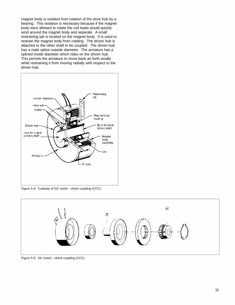
magnet body is isolated from rotation of the drive hub by abearing. This isolation is necessary because if the magnetbody were allowed to rotate the coil leads would quicklywind around the magnet body and separate. A smallrestraining tab is located on the magnet body. It is used torestrain the magnet body from rotating. The driven hub isattached to the other shaft to be coupled. The driven hubhas a male spline outside diameter. The armature has asplined inside diameter which rides on the driven hub.This permits the armature to move back an forth axiallywhile restraining it from moving radially with respect to thedriven hub.
Figure 5-4: Cutaway of DC clutch - clutch coupling (CCC)
11
Figure 5-5: DC clutch - clutch coupling (CCC)
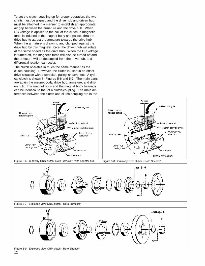
To set the clutch-coupling up for proper operation, the twoshafts must be aligned and the drive hub and driven hubmust be attached in a manner to establish an appropriateair gap between the armature and the drive hub. WhenDC voltage is applied to the coil of the clutch, a magneticforce is induced in the magnet body and passes thru thedrive hub to attract the armature towards the drive hub.When the armature is drawn to and clamped against thedrive hub by this magnetic force, the driven hub will rotateat the same speed as the drive hub. When the DC voltageis turned off, the magnetic force will also be turned off andthe armature will be decoupled from the drive hub, anddifferential rotation can occur. The clutch operates in much the same manner as theclutch-coupling. However, the clutch is used in an offsetdrive situation with a sprocket, pulley, sheave, etc. A typi-cal clutch is shown in Figures 5-6 and 5-7. The main partsare again the magnet body, drive hub, armature, and driv-en hub. The magnet body and the magnet body bearingscan be identical to that of a clutch-coupling. The main dif-ferences between the clutch and clutch-coupling are in the
12Figure 5-9: Exploded view CRP clutch - Roto Sheave®
Figure 5-7: Exploded view CRS clutch - Roto Sprocket®
Figure 5-6: Cutaway CRS clutch- Roto Sprocket® with adapter hub Figure 5-8: Cutaway CRP clutch - Roto Sheave®
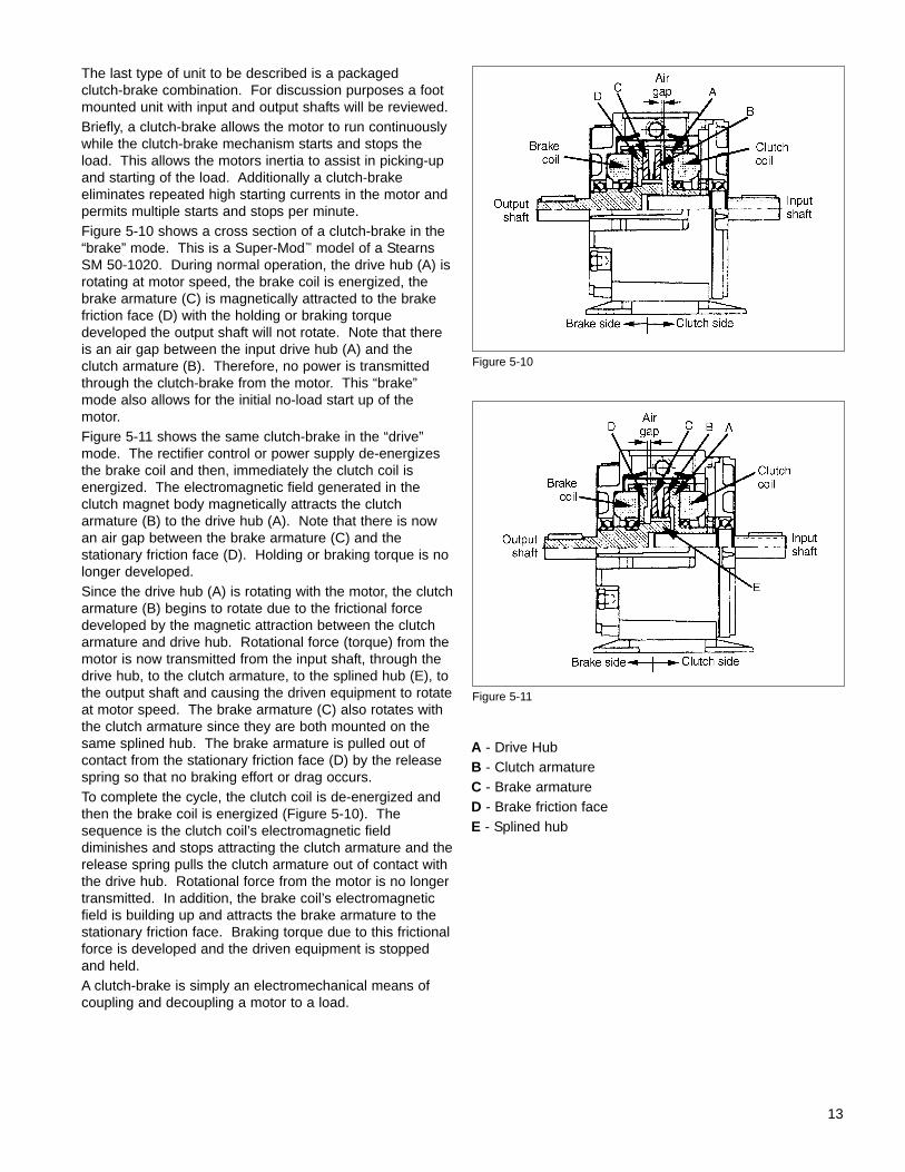
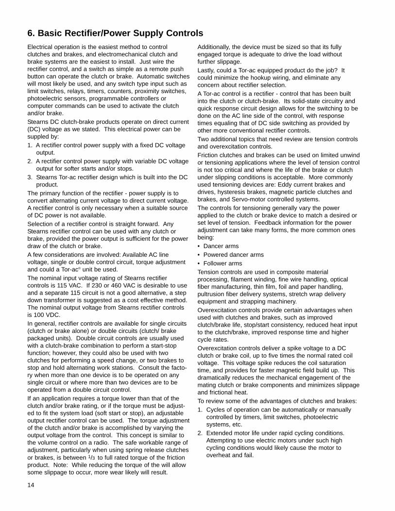
The last type of unit to be described is a packaged clutch-brake combination. For discussion purposes a foot mounted unit with input and output shafts will be reviewed.Briefly, a clutch-brake allows the motor to run continuouslywhile the clutch-brake mechanism starts and stops theload. This allows the motors inertia to assist in picking-upand starting of the load. Additionally a clutch-brake eliminates repeated high starting currents in the motor andpermits multiple starts and stops per minute.Figure 5-10 shows a cross section of a clutch-brake in the“brake” mode. This is a Super-Mod™ model of a StearnsSM 50-1020. During normal operation, the drive hub (A) isrotating at motor speed, the brake coil is energized, thebrake armature (C) is magnetically attracted to the brakefriction face (D) with the holding or braking torque developed the output shaft will not rotate. Note that thereis an air gap between the input drive hub (A) and theclutch armature (B). Therefore, no power is transmittedthrough the clutch-brake from the motor. This “brake”mode also allows for the initial no-load start up of themotor.Figure 5-11 shows the same clutch-brake in the “drive”mode. The rectifier control or power supply de-energizesthe brake coil and then, immediately the clutch coil is energized. The electromagnetic field generated in theclutch magnet body magnetically attracts the clutch armature (B) to the drive hub (A). Note that there is nowan air gap between the brake armature (C) and the stationary friction face (D). Holding or braking torque is nolonger developed.Since the drive hub (A) is rotating with the motor, the clutcharmature (B) begins to rotate due to the frictional forcedeveloped by the magnetic attraction between the clutcharmature and drive hub. Rotational force (torque) from themotor is now transmitted from the input shaft, through thedrive hub, to the clutch armature, to the splined hub (E), tothe output shaft and causing the driven equipment to rotateat motor speed. The brake armature (C) also rotates withthe clutch armature since they are both mounted on thesame splined hub. The brake armature is pulled out ofcontact from the stationary friction face (D) by the releasespring so that no braking effort or drag occurs.To complete the cycle, the clutch coil is de-energized andthen the brake coil is energized (Figure 5-10). Thesequence is the clutch coil’s electromagnetic field diminishes and stops attracting the clutch armature and therelease spring pulls the clutch armature out of contact withthe drive hub. Rotational force from the motor is no longertransmitted. In addition, the brake coil’s electromagneticfield is building up and attracts the brake armature to thestationary friction face. Braking torque due to this frictionalforce is developed and the driven equipment is stoppedand held.A clutch-brake is simply an electromechanical means ofcoupling and decoupling a motor to a load.
A - Drive HubB - Clutch armatureC - Brake armatureD - Brake friction faceE - Splined hub
Figure 5-10
13
Figure 5-11
Electrical operation is the easiest method to control clutches and brakes, and electromechanical clutch andbrake systems are the easiest to install. Just wire the rectifier control, and a switch as simple as a remote pushbutton can operate the clutch or brake. Automatic switcheswill most likely be used, and any switch type input such aslimit switches, relays, timers, counters, proximity switches,photoelectric sensors, programmable controllers or computer commands can be used to activate the clutchand/or brake.Stearns DC clutch-brake products operate on direct current(DC) voltage as we stated. This electrical power can besuppled by:1. A rectifier control power supply with a fixed DC voltage
output.2. A rectifier control power supply with variable DC voltage
output for softer starts and/or stops.3. Stearns Tor-ac rectifier design which is built into the DC
product. The primary function of the rectifier - power supply is toconvert alternating current voltage to direct current voltage.A rectifier control is only necessary when a suitable sourceof DC power is not available.Selection of a rectifier control is straight forward. AnyStearns rectifier control can be used with any clutch orbrake, provided the power output is sufficient for the powerdraw of the clutch or brake.A few considerations are involved: Available AC line voltage, single or double control circuit, torque adjustmentand could a Tor-ac® unit be used.The nominal input voltage rating of Stearns rectifier controls is 115 VAC. If 230 or 460 VAC is desirable to useand a separate 115 circuit is not a good alternative, a stepdown transformer is suggested as a cost effective method.The nominal output voltage from Stearns rectifier controlsis 100 VDC.In general, rectifier controls are available for single circuits(clutch or brake alone) or double circuits (clutch/ brakepackaged units). Double circuit controls are usually usedwith a clutch-brake combination to perform a start-stopfunction; however, they could also be used with two clutches for performing a speed change, or two brakes tostop and hold alternating work stations. Consult the facto-ry when more than one device is to be operated on anysingle circuit or where more than two devices are to beoperated from a double circuit control.If an application requires a torque lower than that of theclutch and/or brake rating, or if the torque must be adjust-ed to fit the system load (soft start or stop), an adjustable output rectifier control can be used. The torque adjustmentof the clutch and/or brake is accomplished by varying theoutput voltage from the control. This concept is similar tothe volume control on a radio. The safe workable range ofadjustment, particularly when using spring release clutchesor brakes, is between 1/3 to full rated torque of the frictionproduct. Note: While reducing the torque of the will allowsome slippage to occur, more wear likely will result.
Additionally, the device must be sized so that its fullyengaged torque is adequate to drive the load without further slippage.Lastly, could a Tor-ac equipped product do the job? Itcould minimize the hookup wiring, and eliminate any concern about rectifier selection.A Tor-ac control is a rectifier - control that has been builtinto the clutch or clutch-brake. Its solid-state circuitry andquick response circuit design allows for the switching to bedone on the AC line side of the control, with responsetimes equaling that of DC side switching as provided byother more conventional rectifier controls.Two additional topics that need review are tension controlsand overexcitation controls.Friction clutches and brakes can be used on limited unwindor tensioning applications where the level of tension controlis not too critical and where the life of the brake or clutchunder slipping conditions is acceptable. More commonlyused tensioning devices are: Eddy current brakes anddrives, hysteresis brakes, magnetic particle clutches andbrakes, and Servo-motor controlled systems.The controls for tensioning generally vary the powerapplied to the clutch or brake device to match a desired orset level of tension. Feedback information for the poweradjustment can take many forms, the more common onesbeing:• Dancer arms• Powered dancer arms• Follower armsTension controls are used in composite material processing, filament winding, fine wire handling, opticalfiber manufacturing, thin film, foil and paper handling, pultrusion fiber delivery systems, stretch wrap deliveryequipment and strapping machinery.Overexcitation controls provide certain advantages whenused with clutches and brakes, such as improvedclutch/brake life, stop/start consistency, reduced heat inputto the clutch/brake, improved response time and highercycle rates.Overexcitation controls deliver a spike voltage to a DCclutch or brake coil, up to five times the normal rated coilvoltage. This voltage spike reduces the coil saturationtime, and provides for faster magnetic field build up. Thisdramatically reduces the mechanical engagement of themating clutch or brake components and minimizes slippageand frictional heat.To review some of the advantages of clutches and brakes:1. Cycles of operation can be automatically or manually
controlled by timers, limit switches, photoelectric systems, etc.
2. Extended motor life under rapid cycling conditions.Attempting to use electric motors under such highcycling conditions would likely cause the motor to overheat and fail.
14
6. Basic Rectifier/Power Supply Controls

3. Reduce overall electrical power consumption from utilitycompanies. The electric motors are running continuously and the clutch-brakes accomplish thestarts and/or stops, therefore the high current draw of amotor start-up under load is avoided.
4. The motor’s inertia is put to useful work, by being available to help start and accelerate a load.
5. Provides a simple and easily controllable means tomechanically connect and disconnect a load from amotor or other prime mover source.
15
For most applications where starting or stopping time anddistance is not an important factor, a simple two step selec-tion is all that’s necessary.STEP ONE: Determine function and type
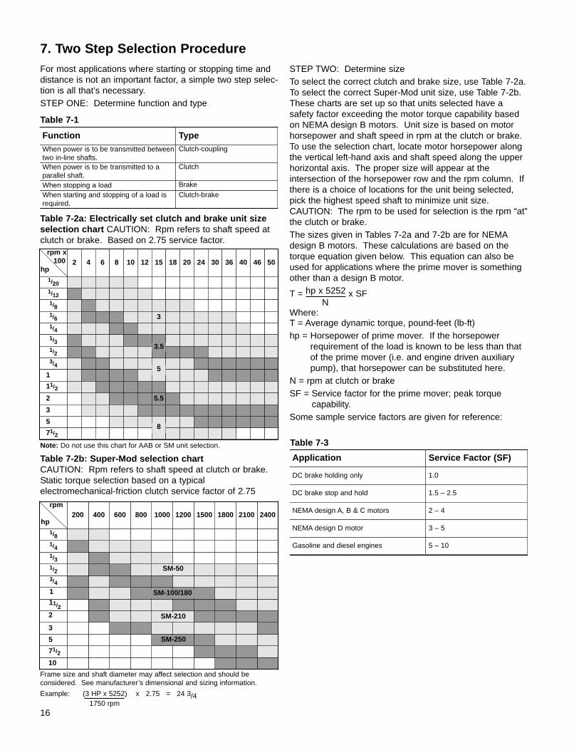
STEP TWO: Determine sizeTo select the correct clutch and brake size, use Table 7-2a.To select the correct Super-Mod unit size, use Table 7-2b.These charts are set up so that units selected have a safety factor exceeding the motor torque capability basedon NEMA design B motors. Unit size is based on motorhorsepower and shaft speed in rpm at the clutch or brake.To use the selection chart, locate motor horsepower alongthe vertical left-hand axis and shaft speed along the upperhorizontal axis. The proper size will appear at the intersection of the horsepower row and the rpm column. Ifthere is a choice of locations for the unit being selected,pick the highest speed shaft to minimize unit size. CAUTION: The rpm to be used for selection is the rpm “at”the clutch or brake.The sizes given in Tables 7-2a and 7-2b are for NEMAdesign B motors. These calculations are based on thetorque equation given below. This equation can also beused for applications where the prime mover is somethingother than a design B motor.
T = hp x 5252 x SF
Where:T = Average dynamic torque, pound-feet (lb-ft)hp = Horsepower of prime mover. If the horsepower
requirement of the load is known to be less than thatof the prime mover (i.e. and engine driven auxiliarypump), that horsepower can be substituted here.
N = rpm at clutch or brakeSF = Service factor for the prime mover; peak torque
capability.Some sample service factors are given for reference:
Table 7-1
16
7. Two Step Selection Procedure
Function TypeWhen power is to be transmitted betweentwo in-line shafts.
Clutch-coupling
When power is to be transmitted to aparallel shaft.
Clutch
When stopping a load Brake
When starting and stopping of a load isrequired.
Clutch-brake
Table 7-2a: Electrically set clutch and brake unit sizeselection chart CAUTION: Rpm refers to shaft speed atclutch or brake. Based on 2.75 service factor.
rpm x100
hp2 4 6 8 10 12 15 18 20 24 30 36 40 5046
1/201/121/81/6 31/41/31/23/4
1
11/2
2 5.5
3
5
71/2
10
71/2
5
3
2
11/2
1
3/4
1/2
1/3
1/4
1/8
240021001800150012001000800600400200rpm
hp
5
8
SM-50
SM-100/180
Table 7-2b: Super-Mod selection chartCAUTION: Rpm refers to shaft speed at clutch or brake. Static torque selection based on a typical electromechanical-friction clutch service factor of 2.75
Note: Do not use this chart for AAB or SM unit selection.
N
Application Service Factor (SF)
DC brake holding only 1.0
DC brake stop and hold 1.5 – 2.5
NEMA design A, B & C motors 2 – 4
Gasoline and diesel engines
NEMA design D motor
5 – 10
3 – 5
Table 7-3
3.5
Frame size and shaft diameter may affect selection and should be considered. See manufacturer’s dimensional and sizing information.
Example: (3 HP x 5252) x 2.75 = 24 3/4
SM-210
SM-250
1750 rpm

PrecautionsThis two-step selection procedure can be used for sizingmost clutch-brake applications. Example of the few situations where it should not be used are as follows:1. Applications where it is necessary to start or stop the
load within a given time.2. Applications involving high cycling rates.3. Applications where there is a large flywheel effect on
the drive or driven side of the clutch or brake.4. Applications where the ambient temperature is not
within 0° to 40° C (32° to 104° F).5. Applications below 300 rpm.In these type of applications, further calculations must bemade by the customer prior to selecting the proper sizeunit or be referred to an application engineer for selectionassistance.Application examplesAlthough the clutch and brake selection procedures arebasically straight forward, the following examples in theuse of the selection chart will illustrate an approach to solv-ing the application problem.CASE ONE: A motor is connected directly to a load inputshaft (Figure 7-1). The motor is a standard NEMA Bdesign and rated at 2 horsepower with a base speed of1800 rpm. A clutch is to be used to prevent prematuremotor “burn out” due to the energy that the motor has todissipate when accelerating the load. As the motor shaft isto be connected to the load shaft, a clutch coupling isrequired.Referring the motor horsepower and base speed to theclutch selection chart 7-2a, the selection is a size 5.5clutch coupling (CCC-55).CASE TWO: A motor is connected to a load thru a 10:1gear reducer (Figure 7-2). The clutch must be applied tothe low speed shaft due to space limitations. The motor isa standard NEMA B design and rated at 1 horsepower witha base speed of 1800 rpm. The reducer shaft is to be connected to the load shaft; therefore, a clutch coupling isrequired.Referring the motor horsepower and the reducer outputspeed to the clutch selection chart 7-2a, the selection is asize 8 clutch coupling (CCC-80).CASE THREE: A motor is connected to a load thru areducer with a further belt reduction on the output of thereducer (Figure 7-3). The motor is a standard NEMA Bdesign and rated at 1 horsepower with a base speed of3600 rpm. The gear reducer has a 2:1 ratio. The beltreduction is 4.5:1. A clutch and brake are required toextend motor life and provide for additional cycles per hour.Minimum down time, and easy clutch-brake maintenancewithout shifting equipment are primary requirements.Therefore, a foot mounted clutch-brake combination isselected. There are three possible locations for the unit:(1) between the motor and the reducer, (2) on the outputshaft of the reducer, and (3) on the input shaft of the load.Referring the motor horsepower and the three speed conditions of the clutch selection chart, the selections are:
1. 1 hp at 3600 rpm – SM-50-2030B2. 1 hp at 1800 rpm – SM-50-2030B3. 1 hp at 400 rpm – SM-180-2030B
17
Figure 7-1: Case one application example
Figure 7-2: Case two application example
Figure 7-3: Case three application example
The following presentation explains the common methodsof using information about the application to select theproper clutch or brake. The information presented may beapplicable to other types of clutches and brakes, however,the emphasis has been on the single disc direct actingtype of clutches and brakes. The application engineering formulas presented are developed to show how they relateto the basic torque formulas and terms used every day inthe power transmission industry. The intent has been topoint out what factors in an application are important andto explain why.Fundamentals of power transmissionIn order to better understand the application of Stearnsbrakes and clutches, it is necessary to again review thebasic terms and mechanical laws of elementary physics.The following information deals with these basic terms andmechanical laws.ForceA force is defined as that which tends to cause motion andcan be either a push or a pull. It is usually expressed inthe English system of weights and measures of ounces,pounds, tons, or “newtons”.TorqueTorque is derived from the Latin term “torquere” whichmeans “to twist”. Technically, torque is a force whichproduces a twist or turning effort.In the application of clutches and brakes, as in the rest ofthe power transmission industry, torque is the basic dimension from which many of the more complex computations are derived. The first part of our review willshow the basic torque formula is used throughout thepower transmission industry.There are two values which determine torque. They are:1. Force2. DistanceIf a force is applied to a jack handle at some distance fromthe lug nut on a wheel, torque is developed. Furthermore,if the jack handle is made longer, the magnitude of torqueapplied to the wheel nut is greater. Therefore, the distanceat which the force is applied is measured from the centerof rotation. The most basic formula to determine torque is:T = F X RWhere:F = Force expressed in weight: e.g., lbs.R = Radius at which the force is applied from the center of
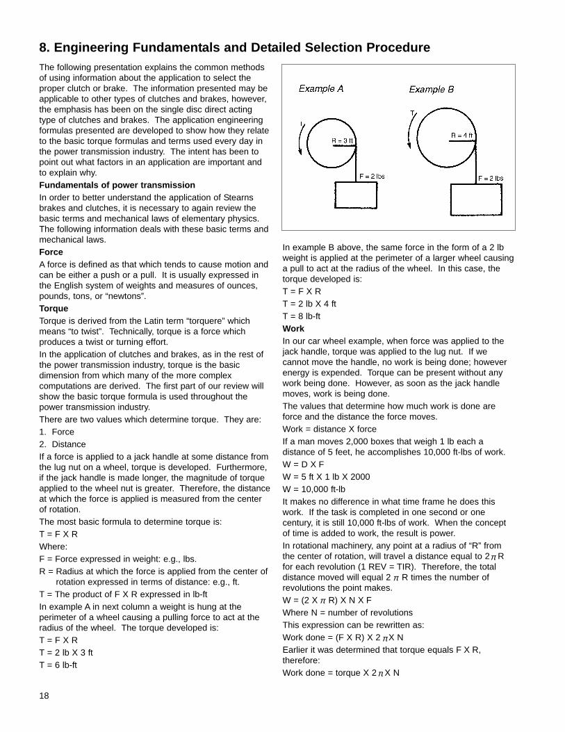
rotation expressed in terms of distance: e.g., ft.T = The product of F X R expressed in lb-ftIn example A in next column a weight is hung at theperimeter of a wheel causing a pulling force to act at theradius of the wheel. The torque developed is:T = F X RT = 2 lb X 3 ftT = 6 lb-ft
In example B above, the same force in the form of a 2 lbweight is applied at the perimeter of a larger wheel causinga pull to act at the radius of the wheel. In this case, thetorque developed is:T = F X RT = 2 lb X 4 ftT = 8 lb-ftWorkIn our car wheel example, when force was applied to thejack handle, torque was applied to the lug nut. If we cannot move the handle, no work is being done; howeverenergy is expended. Torque can be present without anywork being done. However, as soon as the jack handlemoves, work is being done.The values that determine how much work is done areforce and the distance the force moves.Work = distance X forceIf a man moves 2,000 boxes that weigh 1 lb each adistance of 5 feet, he accomplishes 10,000 ft-lbs of work.W = D X FW = 5 ft X 1 lb X 2000W = 10,000 ft-lbIt makes no difference in what time frame he does thiswork. If the task is completed in one second or one century, it is still 10,000 ft-lbs of work. When the conceptof time is added to work, the result is power.In rotational machinery, any point at a radius of “R” fromthe center of rotation, will travel a distance equal to 2 Rfor each revolution (1 REV = TIR). Therefore, the total distance moved will equal 2 R times the number of revolutions the point makes.W = (2 X R) X N X FWhere N = number of revolutionsThis expression can be rewritten as:Work done = (F X R) X 2 X NEarlier it was determined that torque equals F X R, therefore:Work done = torque X 2 X N
π
18
8. Engineering Fundamentals and Detailed Selection Procedure
π
π
π
π
π
HorsepowerPower, in mechanics, is the product of force and distancedivided by time; it is also stated as the performance of agiven amount of work in a given time.Kilowatts and horsepower are the two values commonlyused to express power. In power transmission systems wemost frequently use horsepower. This measurement wasdeveloped by a Scottish Engineer, James Watt, who examined the concepts of work and power, or the rate ofdoing work by using English Dray horses. He found thaton average, one horse could do work at a rate of 33,000 ft-lbsper minute. This rate came to be called horsepower and isthe standard unit of mechanical power used today.1 hp = 33,000 ft-lbs/minIn our previous example, if the man who moved the 2,000one pound boxes did so in 50 minutes, then the averagehorsepower expended was:
hp = 10,000 ft-lbs ÷ 33,000 ft-lb
hp = .006
Note that horsepower is a “rate” of doing work. As such itis sensitive to time, therefore, it takes more horsepower todo a given amount of work in a shorter period of time thana longer period of time.This is of particular importance in clutch applications wherethe clutch is sized at motor running torque, but used tostart a heavy load. The customer may say that the clutchwill see 7 hp but he uses a 10 hp motor. The clutch mustbe able to transmit the highest horsepower demanded andif it can’t, it will slip and eventually burn up.Relationship between work, torque, horsepower andspeedIt was previously determined that:Work = torque X 2 X Nand since,1 hp = 33,000 ft-lbs per minute of worktherefore:
hp = torque X 2 X N
Since,2 = 1
Where:
N = Number of revolutions
T = TorqueThe horsepower formula can be reduced to:
hp = T X N
or, solving for torque:
T = hp X 5,252
This is the basic formula used in the application of power-transmission products. It is also the basic formulaused in the application of clutches and brakes. It showsclearly the factors most readily available in application
problems, i.e., hp and rpm. Furthermore, it shows thattorque selection is a function of the physical forces, workand time required by an application. These factors are allobtainable if you know what to look for.Friction clutches and brakes have two different torqueratings; static and dynamic.Static torque - is defined as the torque between friction sur-faces at the point when relative motion first occursbetween the surfaces. This is sometimes referred to as“breakaway” torque and can be further defined as themaximum “holding” torque.
Dynamic torque - is defined as the torque that existsbetween two friction surfaces that have relative motionbetween them. The dynamic torque is always lower thanthe static torque and will vary in value with the slippingspeed. The dynamic torque is of the lowest value at thehighest slip differential and approaches the static torque asthe slip differential approaches zero.The reason for the different values of static and dynamictorque is due to the different frictional forces. The frictionalforce between two stationary objects, (static) is greaterthan the frictional force between the same two objectswhere there is relative motion (dynamic).Pushing a heavy carton across the floor is an everydayexample of the difference between static and dynamic frictional forces. A certain amount of force is required toovercome the static frictional force between the carton andthe floor. However, once the carton is moving, the forcerequired to keep it moving (and overcome the dynamic frictional force between the carton and floor) is substantially less.Shown in Figure 8-1 is a typical dynamic torque curvewhich represents what would normally happen to thetorque of a clutch or brake as the relative speed betweenthe drive and driven elements of the unit increases. Notethat at 0 rpm speed difference, the actual torque is equal tothe rated static torque and as the relative speed increases,the transmitted torque decreases.This concept is particularly important in beginning to under-stand the application of clutches and brakes because itdescribes a key characteristic of the product. That is com-plete engagement is not instantaneous. It takes someamount of time to overcome the inertia caused by thespeed difference between the drive and driven elements.Therefore, 100% of the torque that a unit is capable oftransmitting, will not actually be transmitted at the momentthe unit is activated and this fact must be taken intoaccount in making a clutch or brake selection. There willbe some delay caused by inertia between the time of activation and the time that a unit is transmitting the ratedtorque.
π
π
19
min.50 minutes
π
33,000
33,000 5,252
5,252
N
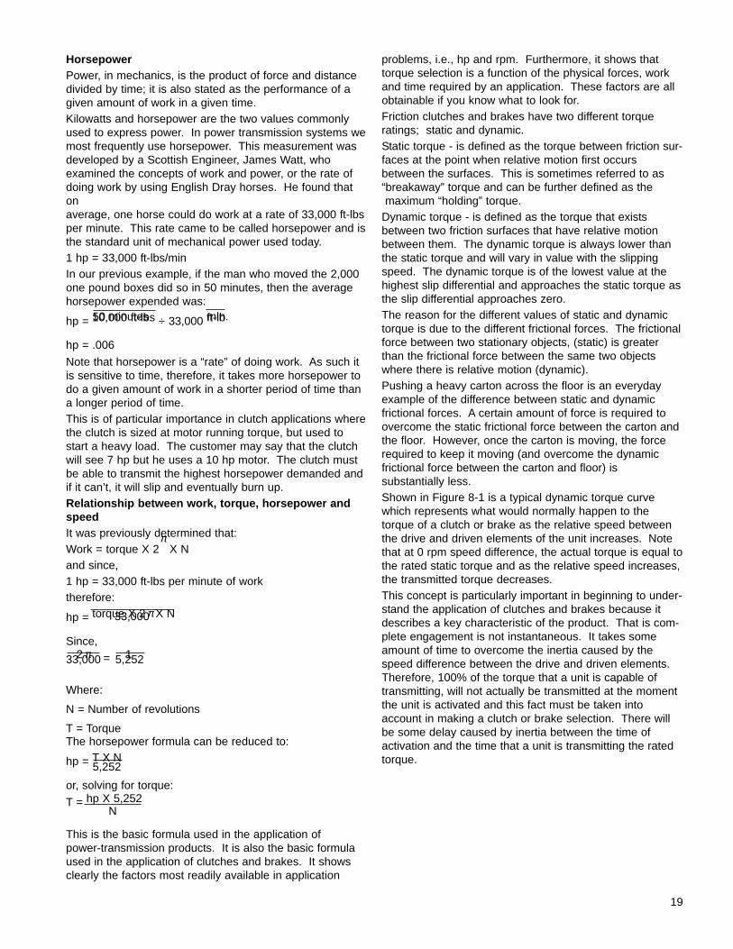
Relationship between magnetism and torque buildup
When an electrical current is applied to a coil in a magnetbody, a magnetic force is developed. As the force develops, and the armature pulls into contact with the friction face of the drive hub, torque begins to build up.This buildup of torque is a fixed ratio of rate of magnetismbuildup and is called the engagement curve. At time 0,rated coil voltage is applied and current begins to build. Asthe current builds, the magnetic force increases. At timeT1, the magnetic force is strong enough to pull in thearmature and from that point transmitted torque begins tobuild. At time T3, 100% of the rated torque is available forstarting or stopping a load. The importance of this relationship is that when an electrical signal is received bya clutch or brake, the load does not instantaneously startor stop. Therefore, the engagement and disengagementtimes must be factored into the application. This mayseem like an inconsequential period of time (milliseconds),but if a customer has an application requiring extremelyhigh cycle rates, or requires very accurate stopping dis-tances, it becomes necessary to consider time even assmall asmilliseconds.
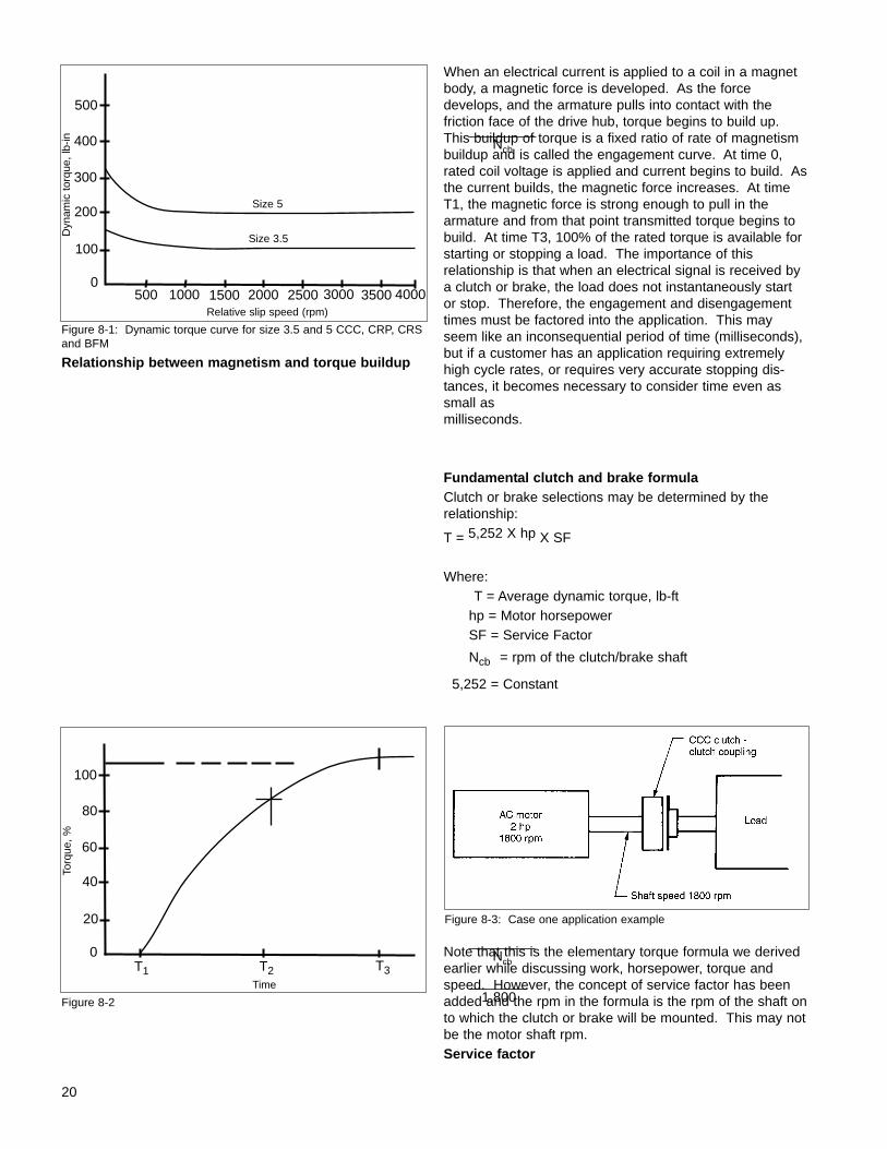
Fundamental clutch and brake formulaClutch or brake selections may be determined by therelationship:
T = 5,252 X hp X SF
Where:T = Average dynamic torque, lb-ft
hp = Motor horsepowerSF = Service Factor
Ncb = rpm of the clutch/brake shaft
5,252 = Constant
Note that this is the elementary torque formula we derivedearlier while discussing work, horsepower, torque andspeed. However, the concept of service factor has beenadded and the rpm in the formula is the rpm of the shaft onto which the clutch or brake will be mounted. This may notbe the motor shaft rpm.Service factor
20
Figure 8-1: Dynamic torque curve for size 3.5 and 5 CCC, CRP, CRSand BFM
Figure 8-2
Ncb
Figure 8-3: Case one application example
Ncb
1,800
500
400
300
100
0500 2000 4000
Dyn
amic
tor
que,
lb-in
Relative slip speed (rpm)
200
1000 1500 2500 3000 3500
100
80
60
20
0T3
Torq
ue,
%
Time
40
T1 T2
Size 5
Size 3.5
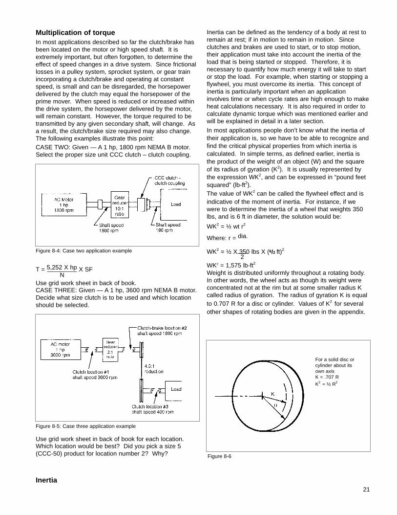
Multiplication of torqueIn most applications described so far the clutch/brake hasbeen located on the motor or high speed shaft. It isextremely important, but often forgotten, to determine theeffect of speed changes in a drive system. Since frictionallosses in a pulley system, sprocket system, or gear trainincorporating a clutch/brake and operating at constantspeed, is small and can be disregarded, the horsepowerdelivered by the clutch may equal the horsepower of theprime mover. When speed is reduced or increased withinthe drive system, the horsepower delivered by the motor,will remain constant. However, the torque required to betransmitted by any given secondary shaft, will change. Asa result, the clutch/brake size required may also change.The following examples illustrate this point:CASE TWO: Given — A 1 hp, 1800 rpm NEMA B motor.Select the proper size unit CCC clutch – clutch coupling.
T = 5,252 X hp X SF
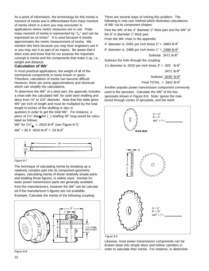
Use grid work sheet in back of book.CASE THREE: Given — A 1 hp, 3600 rpm NEMA B motor.Decide what size clutch is to be used and which locationshould be selected.
Use grid work sheet in back of book for each location.Which location would be best? Did you pick a size 5(CCC-50) product for location number 2? Why?
Inertia
Inertia can be defined as the tendency of a body at rest toremain at rest; if in motion to remain in motion. Sinceclutches and brakes are used to start, or to stop motion,their application must take into account the inertia of theload that is being started or stopped. Therefore, it is necessary to quantify how much energy it will take to startor stop the load. For example, when starting or stopping aflywheel, you must overcome its inertia. This concept ofinertia is particularly important when an applicationinvolves time or when cycle rates are high enough to makeheat calculations necessary. It is also required in order tocalculate dynamic torque which was mentioned earlier andwill be explained in detail in a later section.
In most applications people don’t know what the inertia oftheir application is, so we have to be able to recognize andfind the critical physical properties from which inertia is calculated. In simple terms, as defined earlier, inertia isthe product of the weight of an object (W) and the squareof its radius of gyration (K2). It is usually represented bythe expression WK2, and can be expressed in “pound feetsquared” (lb-ft2).The value of WK2 can be called the flywheel effect and isindicative of the moment of inertia. For instance, if wewere to determine the inertia of a wheel that weights 350lbs, and is 6 ft in diameter, the solution would be:
WK2 = ½ wt r2
Where: r = dia.
WK2 = ½ X 350 lbs X (6/2 ft)2
WK2 = 1,575 lb-ft2
Weight is distributed uniformly throughout a rotating body.In other words, the wheel acts as though its weight wereconcentrated not at the rim but at some smaller radius Kcalled radius of gyration. The radius of gyration K is equalto 0.707 R for a disc or cylinder. Values of K2 for severalother shapes of rotating bodies are given in the appendix.
21
Figure 8-4: Case two application example
N
Figure 8-5: Case three application example
2
Figure 8-6
For a solid disc orcylinder about itsown axisK = .707 RK2 = ½ R2
As a point of information, the terminology for this inertia ismoment of inertia and is differentiated from mass momentof inertia which is a term you may encounter in applications where metric measures are in use. Polarmass moment of inertia is represented by “Jm” and can beexpressed as oz-in/sec2. It is used because it closelyapproximates the metric measurement of inertia. We mention this here because you may hear engineers use itor you may see it as part of an inquiry. Be aware that itdoes exist and know that for our purpose the importantconcept is inertia and the components that make it up, i.e.,weight and distance.Calculation of Wk2
In most practical applications, the weight of all of themechanical components is rarely known or given.Therefore, calculation of inertia can become difficult.However, there are some approximations and shortcutswhich can simplify the calculations.
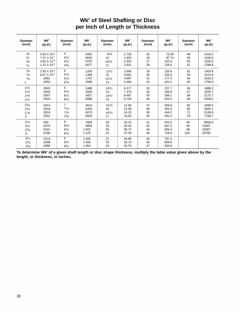
To determine the Wk2 of a steel part, the appendix includesa chart with the calculated Wk2 for solid steel shafting anddiscs from 1/8” to 102” diameter. Note that this table givesWk2 per inch of length and must be multiplied by the totallength in inches of the shafting or disc in question in order to get the total Wk2. For instance, apiece of 1½” diameter ( ) shafting 30” long would be calcu-lated as follows:Wk2 for 1½” = .0010 lb-ft2 (see Figure 8-7)
Wk2 = 30 X .0010 lb-ft2 = .03 lb-ft2
The technique of calculating inertia by breaking up a relatively complex part into its component geometricshapes, calculating inertia of those relatively simple partsand totalling those figures, is widely used. Inertias forbasic power transmission parts are generally availablefrom the manufacturers, however the Wk2 can be calculat-ed if the manufacturer’s figures are not available.Example: Calculate the inertia of the following coupling:
There are several ways of solving this problem. The following is only one method which illustrates calculationsof Wk2 via its component shapes:
Find the Wk2 of the 4” diameter 2” thick part and the Wk2 ofthe 6” in diameter 1” thick part.From the Wk2 chart in the appendix:
4” diameter is .0491 per inch times 2” = .0983 lb-ft2
6” diameter is .2488 per inch times 1” = .2488 lb-ft2
Subtotal .3471 lb-ft2
Subtract the hole through the coupling.
1½ diameter is .0010 per inch times 3” = .003 lb-ft2
.3471 lb-ft2
Subtract .0030 lb-ft2
Final TOTAL = .3441 lb-ft2
Another popular power transmission component commonlyused is the sprocket. Calculate the Wk2 of the twosprockets shown in Figure 8-9. Note: Ignore the holebored through center of sprockets, and the teeth.
Likewise, most power transmission components can bebroken down into simple discs and hollow cylinders inorder to calculate their inertia. For instance, to determine
Figure 8-7
Figure 8-8
Figure 8-9
A = ½”B = 15”WK2 = ? = __________
A = ½”B = 5”WK2 = ? = __________
22
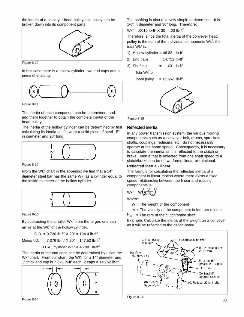
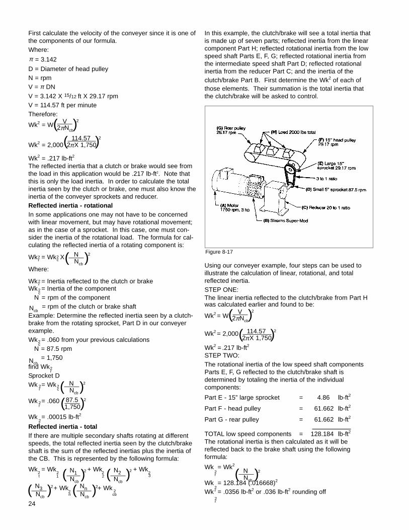
the inertia of a conveyer head pulley, this pulley can bebroken down into its component parts.
In this case there is a hollow cylinder, two end caps and apiece of shafting.
The inertia of each component can be determined, andadd them together to obtain the complete inertia of thehead pulley.The inertia of the hollow cylinder can be determined by firstcalculating its inertia as if it were a solid piece of steel 15”in diameter and 20” long.
From the Wk2 chart in the appendix we find that a 14”diameter steel bar has the same Wk2 as a cylinder equal tothe inside diameter of the hollow cylinder.
By subtracting the smaller Wk2 from the larger, one can
arrive at the Wk2 of the hollow cylinder.
O.D. = 9.720 lb-ft2 X 20” = 194.4 lb-ft2
Minus I.D. = 7.376 lb-ft2 X 20” = 147.52 lb-ft2
TOTAL cylinder WK2 = 46.88 lb-ft2
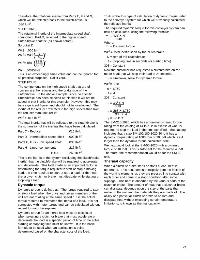
The inertia of the end caps can be determined by using theWk2 chart. From our chart, the WK2 for a 14” diameter and1” thick end cap is 7.376 lb-ft2 each, 2 caps = 14.752 lb-ft2.
The shafting is also relatively simple to determine. It is1½” in diameter and 30” long. Therefore:
Wk2 = .0010 lb-ft2 X 30 = .03 lb-ft2
Therefore, since the total inertia of the conveyer head pulley is the sum of the individual components Wk2, thetotal Wk2 is:
1) Hollow cylinder = 46.88 lb-ft2
2) End caps = 14.752 lb-ft2
3) Shafting = .03 lb-ft2
Total Wk2 of
head pulley = 61.662 lb-ft2
Reflected inertiaIn any power transmission system, the various movingcomponents such as a conveyor belt, drums, sprockets,shafts, couplings, reducers, etc., do not necessarily operate at the same speed. Consequently, it is necessaryto calculate the inertia as it is reflected to the clutch orbrake. Inertia that is reflected from one shaft speed to aclutch/brake can be of two forms; linear or rotational.Reflected inertia - linearThe formula for calculating the reflected inertia of a component in linear motion where there exists a fixedspeed relationship between the linear and rotating components is:
Wk2 = W
Where:W = The weight of the componentV = The velocity of the component in feet per minute
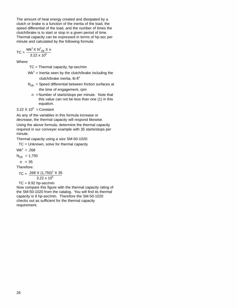
= The rpm of the clutch/brake shaftExample: Calculate the inertia of the weight on a conveyeras it will be reflected to the clutch-brake.
23
Ncb
2 Ncb
Figure 8-13
Figure 8-14Figure 8-16
Figure 8-10
Figure 8-11
Figure 8-12
Figure 8-15
Nπ( )2V
First calculate the velocity of the conveyer since it is one ofthe components of our formula.Where:
= 3.142
D = Diameter of head pulleyN = rpmV = DN
V = 3.142 X 15/12 ft X 29.17 rpmV = 114.57 ft per minuteTherefore:
Wk2 = W
Wk2 = 2,000
Wk2 = .217 lb-ft2
The reflected inertia that a clutch or brake would see fromthe load in this application would be .217 lb-ft2. Note thatthis is only the load inertia. In order to calculate the totalinertia seen by the clutch or brake, one must also know theinertia of the conveyer sprockets and reducer.Reflected inertia - rotationalIn some applications one may not have to be concernedwith linear movement, but may have rotational movement;as in the case of a sprocket. In this case, one must con-sider the inertia of the rotational load. The formula for cal-culating the reflected inertia of a rotating component is:
Wk = Wk X
Where:
Wk = Inertia reflected to the clutch or brakeWk = Inertia of the component
N = rpm of the component= rpm of the clutch or brake shaft
Example: Determine the reflected inertia seen by a clutch-brake from the rotating sprocket, Part D in our conveyerexample.Wk = .060 from your previous calculations
N = 87.5 rpm= 1,750
find Wk Sprocket DWk = Wk
Wk = .060
Wk = .00015 lb-ft2
Reflected inertia - totalIf there are multiple secondary shafts rotating at differentspeeds, the total reflected inertia seen by the clutch/brakeshaft is the sum of the reflected inertias plus the inertia ofthe CB. This is represented by the following formula:
Wk = Wk + Wk + Wk
+ Wk + Wk
In this example, the clutch/brake will see a total inertia thatis made up of seven parts; reflected inertia from the linearcomponent Part H; reflected rotational inertia from the lowspeed shaft Parts E, F, G; reflected rotational inertia fromthe intermediate speed shaft Part D; reflected rotational inertia from the reducer Part C; and the inertia of theclutch/brake Part B. First determine the Wk2 of each ofthose elements. Their summation is the total inertia thatthe clutch/brake will be asked to control.
Using our conveyer example, four steps can be used toillustrate the calculation of linear, rotational, and totalreflected inertia.STEP ONE:The linear inertia reflected to the clutch/brake from Part Hwas calculated earlier and found to be:
Wk2 = W
Wk2 = 2,000
Wk2 = .217 lb-ft2
STEP TWO:The rotational inertia of the low speed shaft componentsParts E, F, G reflected to the clutch/brake shaft is determined by totaling the inertia of the individual components:
Part E - 15” large sprocket = 4.86 lb-ft2
Part F - head pulley = 61.662 lb-ft2
Part G - rear pulley = 61.662 lb-ft2
TOTAL low speed components = 128.184 lb-ft2
The rotational inertia is then calculated as it will bereflected back to the brake shaft using the following formula:
Wk = Wk2
Wk = 128.184 (.016668)2
Wk = .0356 lb-ft2 or .036 lb-ft2 rounding off
24
Nπ
Nπ
2 NcbNπ( )2V
2 X 1,750Nπ( )2114.57
2r
2c Ncb
( )2N
2r
2c
Ncb
2c
Ncb2r
2r
2c Ncb( )2N
2r
2r
2t
2n
Ncb( )2N1 2
2 Ncb( )2N2 2
3
Ncb( )2N3
Ncb( )2Nn 2
cb
Figure 8-17
2 NcbNπ( )2V
2 X 1,750Nπ( )2
2r
Ncb( )2N
2r
2r
1,750( )287.5
12
114.57
Therefore, the rotational inertia from Parts E, F and G,which will be reflected back to the clutch-brake, is .036 lb-ft2.
STEP THREE:The rotational inertia of the intermediate speed shaft component, Part D, reflected to the higher speed clutch-brake shaft is: (as shown before)Sprocket D
Wk = .060 lb-ft2
Wk = Wk
Wk = .060
Wk = .00015 lb-ft2
This is an exceedingly small value and can be ignored forall practical purposes. Call it zero.STEP FOUR:The components on the high speed shaft that are of concern are the reducer and the brake side of theclutch/brake. In the above example, since no specificclutch/brake has been selected at this time it will not beadded in that inertia for this example. However, this maybe a significant figure, and should not be overlooked. Theinertia of the reducer reflected to the high speed shaft fromthe reducer manufacturer is:
Wk2 = .015 lb-ft2
The total inertia that will be reflected to the clutch/brake isthe summation of the inertias that have been calculated.
Part C - Reducer .015 lb-ft2
Part D - Intermediate speed shaft .000 lb-ft2
Parts E, F, G - Low speed shaft .036 lb-ft2
Part H - Linear components .217 lb-ft2
TOTAL .268 lb-ft2
This is the inertia of the system (excluding the clutch/brakeinertia) that the clutch/brake will be required to accelerateand decelerate. This total inertia is an important factor indetermining the torque required to start or stop a movingload, the time required to start or stop a load, or the heatthat a given clutch or brake must dissipate while starting orstopping a load.
Dynamic torqueDynamic torque is defined as: “The torque required to startor stop a load when the drive and driven members of theunit are not rotating at the same speed.” It is the actualtorque required to overcome the inertia of a load. It is notconnected with motor torque and can be calculated withoutregard to motor horsepower.Dynamic torque for an inertia load must be calculatedwhen selecting a clutch or brake that must accelerate ordecelerate the load in a specific period of time or the actualstarting or stopping time must be known. It is the basic formula to be used when an application is being determined based on the characteristics of the load.
To illustrate this type of calculation of dynamic torque, referto the conveyer system for which we previously calculatedthe reflected inertia.The required dynamic torque for this conveyer system cannow be calculated, using the following formula:
Td =
Where:Td = Dynamic torque
Wk2 = Total inertia seen by the clutch/brake
N = rpm of the clutch/braket = Stopping time in seconds (or starting time)
308 = ConstantNow the customer has requested a clutch/brake on themotor shaft that will stop their load in .4 seconds.
Td = Unknown, solve for dynamic torque
Wk2 = .268
n = 1,750t = .4
308= Constant
Td =
Td =
Td = 3.8 lb-ft The SM-210-1020, which has a nominal dynamic torquerating from the catalog of 44 lb-ft, is in excess of what isrequired to stop the load in the time specified. The catalogindicates that a size SM-100/180-1020 20 lb-ft has adynamic torque rating at 1800 rpm of 20 lb-ft which is stilllarger than the dynamic torque calculated here.We next could look at the SM-50-1020 with a dynamictorque of 10 lb-ft. This is sufficient for the required 4 lb-ft.Therefore, the recommendation would be for the SM-50unit.
Thermal capacityWhen a clutch or brake starts or stops a load, heat is generated. This heat comes principally from the friction ofthe working elements as they are pressed into contact witheach other and come to a static condition after some slippage. This heat is absorbed by the various parts of theclutch or brake. The amount of heat that a clutch or brakecan dissipate, depends upon the size of the parts thatmake up the unit and the materials they are made of. Theability of a particular clutch or brake to absorb and dissipate heat without exceeding certain temperature limitations, is known as thermal capacity.
308tWk2 X N
25
2c
2r
2c
Ncb( )2N
2r
1,750( )287.5
2r
308tWk2 X N
308 X .4.268 X 1,750
26
The amount of heat energy created and dissipated by aclutch or brake is a function of the inertia of the load, thespeed differential of the load, and the number of times theclutch/brake is to start or stop in a given period of time.Thermal capacity can be expressed in terms of hp-sec perminute and calculated by the following formula:
TC =
Where:TC = Thermal capacity, hp-sec/min
Wk2 = Inertia seen by the clutch/brake including the
clutch/brake inertia, lb-ft2
Ncb = Speed differential between friction surfaces atthe time of engagement, rpm
n = Number of starts/stops per minute. Note thatthis value can not be less than one (1) in thisequation.
3.22 X 106 = Constant
As any of the variables in this formula increase ordecrease, the thermal capacity will respond likewise.Using the above formula, determine the thermal capacityrequired in our conveyer example with 35 starts/stops perminute.Thermal capacity using a size SM-50-1020:
TC = Unknown, solve for thermal capacity
Wk2 = .268
Ncb = 1,750
n = 35Therefore:
TC =
TC = 8.92 hp-sec/minNow compare this figure with the thermal capacity rating ofthe SM-50-1020 from the catalog. You will find its thermalcapacity is 9 hp-sec/min. Therefore the SM-50-1020checks out as sufficient for the thermal capacity requirement.
3.22 x 10⁶
Wk2 X N2cb X n
3.22 x 10⁶
.268 X (1,750)2 X 35
The application and selection of DC clutches and brakes isa combination of engineering formulas and approximations.As important as the understanding of these formulas are,you must also take into account the environmental conditions that the product will be subjected to throughoutits lifetime. For example: A friction product should neverbe selected for use in hazardous atmospheres unless ithas been designed, tested and approved for such use byan independent testing laboratory such as UnderwritersLaboratories (UL) or Canadian Standards Association(CSA).To better assist the customer in the selection process andapplication of DC clutches and brakes you need to watchout for unusual environment service conditions such as:• Operation in wet or damp areas• Operation speeds in excess of rated• Exposure to gritty dust• Poor ventilation• Exposure to oil vapor• Exposure to salty air• Exposure to radioactivity• Exposure to mechanical loads involving thrust or
overhung in excess of rated• Exposure to chemical fumes
Many times the customer assumes you know all about hisor her specific application. It takes just a few extra minutesof time to ask questions regarding the operating environment and this time may be very well spent upfrontrather than after troubles begin, because of an unusualoperation condition.Each application can be different and the concepts presented in this program are important in making the optimum product decision. The important points to remember are that electromagnetic DC clutches, brakes,and clutch-brake packages can be very versatile andaccomplish many indexing, cycling, connect-disconnect,and positioning functions. Electromagnetic DC productslike those manufactured by Stearns are most assuredly themore cost effective type for controlling the power flow in amechanical power transmission system.Additionally, Stearns has many years of effective use andexperience with DC products since Stearns originally introduced this product line in 1928.
27
9. Summary

Material handling• Conveyers• Stackers• Bucket elevators• Cranes and hoists (gantry)• Aviation baggage/freight conveyers• Automated storage/retrieval systems• Carousel machinery• Gantry cranes• Steel coil levelers• Feeder machinery
Packaging• Stretch wrap machinery• Palletizers• Strapping machinery• Carton - tape and seal machines• Labeling equipment• Bag and box making machines
Printing/paper handling• Business form presses• Sheet fed presses• Slitters and sheeters• Laminator machines
Machine tools• Lathes• Transfer line equipment• Mill, drill and top machinery• Presses and brakes
Textile machinery• Warpers• Carding machines• Sewing equipment• Knitting machines
Food processing• Bakery ovens• Bottling machinery• Meat saws and processing equipment• Package and wrap equipment• Vending machines• Dough process equipment
Steel mill and foundry equipment• Rolling mill stands• Transfer cars• Drawbench machinery• Cooling fans• Push-pull carts• Heat treat ovens
Mining equipment• Ore buckets and conveyers• Ball mills• Coal handling systems
Special machinery• Saw mill carriages and transfer equipment• Concrete block and brick machines• Fan drives• Pump drives• Laundry equipment• Balancing machines• Shoe manufacturing equipment• Bowling pin setter machinery• IC engine driven mobile equipment• Communication and radar drives• Plywood machinery• Secure door systems• Tire molding equipment• Aviation ground support equipment and
air-conditioning carts• Miscellaneous military equipment
28
10. Typical Stearns DC Product Applications
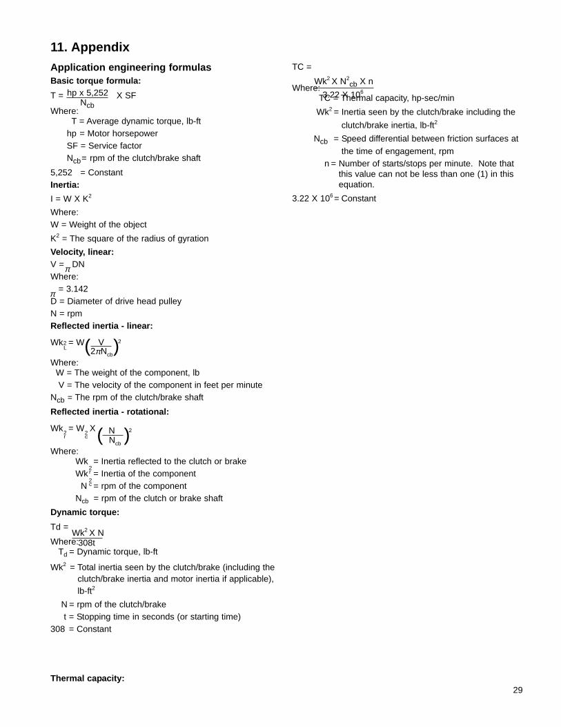
Application engineering formulasBasic torque formula:
T = X SF
Where:T = Average dynamic torque, lb-ft
hp = Motor horsepowerSF = Service factorNcb= rpm of the clutch/brake shaft
5,252 = ConstantInertia:
I = W X K2
Where:W = Weight of the object
K2 = The square of the radius of gyration
Velocity, linear:V = DN Where:
= 3.142D = Diameter of drive head pulleyN = rpmReflected inertia - linear:
Wk = W
Where:W = The weight of the component, lbV = The velocity of the component in feet per minute
Ncb = The rpm of the clutch/brake shaft
Reflected inertia - rotational:
Wk = W X
Where:Wk = Inertia reflected to the clutch or brakeWk = Inertia of the component
N = rpm of the componentNcb = rpm of the clutch or brake shaft
Dynamic torque:
Td =
Where:Td = Dynamic torque, lb-ft
Wk2 = Total inertia seen by the clutch/brake (including theclutch/brake inertia and motor inertia if applicable),lb-ft2
N = rpm of the clutch/braket = Stopping time in seconds (or starting time)
308 = Constant
Thermal capacity:
TC =
Where:TC = Thermal capacity, hp-sec/min
Wk2 = Inertia seen by the clutch/brake including the
clutch/brake inertia, lb-ft2
Ncb = Speed differential between friction surfaces atthe time of engagement, rpm
n = Number of starts/stops per minute. Note thatthis value can not be less than one (1) in thisequation.
3.22 X 106 = Constant
29
11. Appendix
Nπ
Ncb
hp x 5,252
Nπ
2L 2 NcbNπ( )2V
2r
2c Ncb
( )2N
2r
2c
308tWk2 X N
3.22 X 10⁶
Wk2 X N2cb X n
30
Wk2 of Steel Shafting or Disc per Inch of Length or Thickness
Diameter(inch)
Wk2
(lb-ft2)Diameter
(inch)Wk2
(lb-ft2)Diameter
(inch)Wk2
(lb-ft2)Diameter
(inch)Wk2
(lb-ft2)Diameter
(inch)Wk2
(lb-ft2)
1/81/43/81/2
4.53 X 107.47 X 103.83 X 101.21 X 10
441/441/243/4
.0491
.0626
.0787
.0977
93/410101/211
1.7351.9202.3342.811
25262728
75.0087.74
102.0118.0
48495051
1019.21106.81200.01298.9
5/83/47/8
1
2.93 X 106.07 X 10
.0001
.0002
551/451/253/4
.1200
.1458
.1757
.2099
111/212121/213
3.3583.9814.6875.484
29303132
135.8155.5177.3201.3
52535455
1403.81514.91632.51756.9
11/811/413/811/2
.0003
.0005
.0007
.0010
661/461/263/4
.2488
.2930
.3427
.3986
131/214141/215
6.3777.3768.4879.720
33343536
227.7256.6288.1322.5
56575859
1888.22026.72172.72326.5
15/813/417/82
.0013
.0018
.0024
.0031
771/471/273/4
.4610
.5304
.6075
.6926
151/216161/217
11.0812.5814.2316.04
37383940
359.8400.3444.2491.5
60667278
2488.33643.15159.67166.7
21/421/223/43
.005
.0075
.0110
.0156
881/481/283/4
.7864
.88941.0021.125
18192021
20.1525.0230.7237.34
41424344
542.5597.4656.4719.6
849096
102
9558.9125971630720782
31/431/233/4
.0214
.0288
.0380
991/491/2
1.2601.4051.564
222324
44.9853.7363.70
454647
787.3859.6936.9
To determine Wk2 of a given shaft length or disc shape thickness, multiply the table value given above by thelength, or thickness, in inches.
-8
-5
-7
-6
-5
-5
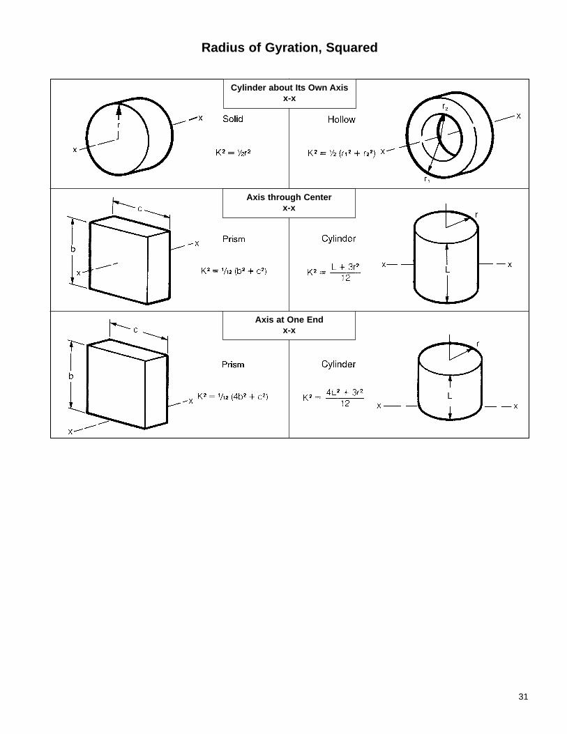
31
Radius of Gyration, Squared
Cylinder about Its Own Axisx-x
Axis through Centerx-x
Axis at One Endx-x
In addition to electrically engaged industrial clutches andbrakes, Stearns Division manufacturers and sells:SINPAC® switchesStearns SINPAC switches represent a revolutionaryapproach to starting split phase, capacitor start, and capac-itor start/capacitor run single-phase induction motors.Reliable solid-state circuitry replaces mechanical centrifugal switch, and actuator.AAB brakesAAB brakes are spring set and electrically released. Thistype of brake develops braking and holding torque in theabsence of electrical power.When electrical power is applied, the armature plate ispulled against the magnet body and the force of the pressure spring by electromagnetic forces. This actionreleases the friction disc, thereby allowing free rotation ofthe brake hub and connected shaft. With removal of theelectrical power, the electromagnetic force is removed(turned-off), and the pressure spring will move the armature plate to clamp the friction disc between the pressure plate and the armature. Braking and holdingtorque is developed by this clamping action and the brakehub transmits the torque to the shaft.AAB brakes are available to meet a wide range of productrequirements. They incorporate asbestos free friction discmaterials and the friction discs are easily replaceable. Ashortened or recessed hub is available for face mountingor to provide for maximum space efficiency. An optional manual release lever is available to allow shaft rotationunder no power or emergency conditions. Customerdesigns and modifications are possible...consult the facto-ry.Heavy duty electric clutches and brakesThe heavy duty line of clutches and brakes are multipledisc, direct acting, DC actuated units. There are threebasic products: The Style E electrically engaged clutch,the SCE spring-engaged, electrically-released clutch, andthe SCEB spring-engaged, electrically-released brakes.The primary markets for these clutches are rolling mills,rotary kilns, rod and ball mills, crushers, pump drives, andemergency standby power systems.Style E electrically engaged clutchStyle E clutches are available in three configurations. Thebasic Style E offers the most economical means of providing heavy duty clutching. Style E clutches offerthese features:• Torque ratings from 140 lb-ft to 9000 lb-ft• Collector rings can be mounted on the drive hub for
minimum diametrical clearance or on the magnet body tominimize overall length
The Style E, Class S series is available with torque ratingsfrom 600 lb-ft to 9000 lb-ft. Style E, Class S clutches offerseveral features that simplify serviceability:• Two-piece collector ring assembly allows replacement
without disassembling clutch
• Detachable drive hub allows replacement of friction discswithout disturbing equipment on either side of clutch
The Style E, Class M series provides torque capabilitiesfrom 3000 lb-ft to 60,000 lb-ft. Style E, Class M clutchesoffers these design features:• Pilot bearing helps correct for minor shaft misalignment• Detachable drive and driven hubs allow replacement of
friction discs without disturbing equipment on either sideof clutch
• Two piece collector ring assembly allows replacementwithout disassembling clutch
Style SCE spring-engaged electrically-released clutchSCE clutches are spring engaged. Thus they require nopower for engaging. Power is only applied to disengagethe clutch.The great force of the engagement springs in the SCEclutch provides high torque in a relatively compact package. The special bronze friction disc cage also permits much higher operating speeds than are availablefrom cast iron cage clutches with equivalent torque ratings.The SCE is available with torque ratings from 450 lb-ftthrough 10,000 lb-ft. All SCE clutches offer these otherdesign features:• Two piece collector ring assembly allows replacement
without disassembling clutch• Detachable drive hub allows replacement of friction disc
without disturbing equipment on either side of clutch.• Manual release screws provided for disengagement in
emergencies and for servicingStyle SCEB spring-engaged, electrically-released brakeStearns SCEB brakes provide higher holding torque perpackage size than most other comparable spring setbrakes. The unique friction disc pack used in these brakesalso allows higher operating speeds per torque rating. Thelow inertia design means that the full brake capacity can beused to stop the load, not the rotating parts of the brake.Stearns SCEB brakes require only simple electrical connections. There is no need for the expensive powersupplies, plumbing connections, and control valves usedfor pneumatic or hydraulic type brakes. All SCEB brakesoffer these additional design features.• Detachable magnet body allows replacement of friction
discs without disturbing equipment connected to brake• Manual release screws provided for disengagement in
emergencies and for servicing• Integral conduit box for safe, simple wiring connections
Stearns solenoid-actuated brakesStearns offers several types of spring engaged disc brakesand are available for:• Industrial duty• Hazardous location• Marine duty• Navy• Maritime duty
Industrial duty brakes
32
12. Other Products
There are two types of enclosures available for industrialbrakes.• Standard enclosures - NEMA 1 and NEMA 2• Dust-tight, waterproof (DTWP) enclosures - NEMA 4 and
NEMA 4XBrakes with standard enclosures are used in locationswhere NEMA Type 1 and 2 enclosures are required. Whenmounted on a NEMA C-face motor, a brake with a standardenclosure is drip-proof. Brakes with NEMA 2 enclosures provide protection against:• Accidental contact with the enclosed electrical
connections and moving components of the brake
• Falling dirt
• Falling liquids and light splashing• Dust, lint, fibers and flyings
Industrial brakes with NEMA 4 enclosures are used in locations where NEMA Type 3 and 4 enclosures arerequired. When mounted on a NEMA C-face motor that isenclosed, such as totally enclosed, non-ventilated (TENV)motor, the brake is dust-tight, waterproof. They are selected for outdoor installations, or where there are moist,abrasive or dusty environments.Brakes with NEMA 4 enclosures provide protection against:• Accidental contact with the enclosed electrical
connections and moving components of the brake• Falling dirt• Falling liquids and light splashing• Lint, fibers and flyings• Windblown dust• Rain, snow and sleet• Low pressure hosedown and splashing water
Brakes with Nema 4X enclosures provide the same protection as the Nema 4 brakes, but also include: corrosion resistance, BISSC certification, meets NationalAAA Dairy Standards, compliance with Wisconsin Foodand Dairy regulations. NEMA 4X brakes are suitable forwashdown applications.Hazardous location brakesCertain installations where explosive gases or ignitabledust are present in the atmosphere, require the use ofStearns hazardous location brakes. The hazardous locations are defined in the National Electrical Code(NEC). For a detailed discussion of these, refer to Bulletin200.The two major differences between Stearns hazardouslocation brakes and industrial brakes are:• Enclosure design• Thermal considerations
The enclosure of a hazardous location brake is designed toprevent flame propagation from inside the brake to the outside atmosphere. This is accomplished through tortuous flame paths having controlled clearances.NOTE: Hazardous location brakes are not waterproof, andprotection from weather and washdowns must be provided.Generally, compliance with the NEC is demonstrated by ULListing of the hazardous location classifications product in
Underwriters Laboratories Location Equipment Directory. Alabel displaying the UL mark and required rating information will be found on each Stearns brake to confirmthe listing. The Canadian Standards Association (CSA)monogram will be found on Stearns hazardous locationbrakes sold in Canada to confirm certification.Stearns motor-mounted, hazardous-location electric discbrakes are Listed only when mounted to a listed hazardous-location motor of the same Class and Group ata UL approved motor manufacturer’s facility, and where thecombination has been accepted by UL or CSA. This procedure completes the explosion-proof assembly of thebrake. However, foot-mounted Listed hazardous-locationdisc brakes are also available for coupling to a motor, andmay be installed by anyone.Marine duty brakesStearns marine duty brakes are available from 10 through1,000 lb-ft. All feature Stearns exclusive self-adjustingmechanism that ends the need for periodic brakeadjustment.A Stearns marine duty brake has a NEMA 4 enclosure(cast iron) with the following special features:• Brass pressure plate• Brass stationary discs• Splined stainless steel hub• Special friction discs• (Optional) special interior coatings or materials
With the exception of these special internal components,marine brakes have the same construction and features ofthe comparable industrial brake models. The brass inter-nal components prevent corrosion from condensation thatmay occur. As added protection against condensation, aspace heater is recommended on all marine duty brakes.Stearns marine duty brakes are suitable for many applications, including capstan, mooring, topping, and vang winches aboard maritime vessels, dry dock winches, andoffshore jackup oil rigs. Marine brakes are designed toconform with the brake specifications in IEEE Standard 45,“IEEE Recommended Practice for Electrical Installations onShipboard.”Navy brakesAll Stearns Navy brakes are designed in accordance withMilitary Specification MIL-B-16392C. With additional modifications, Stearns Navy brakes can also meet MIL-E-17807B. Many of these series are also listed on theNavy’s Qualified Products List, indicating that they havebeen tested recently and approved by the Bureau of Ships.The following features are common to all Navy brakes:• Spraytight or watertight enclosure (NEMA 4)• Ductile iron exterior (housing and endplate)• Brass or ductile iron internal parts (pressure plate and
stationary disc)• Brass or ductile iron support plate• Brass or stainless steel hardware• Special paint per Navy Specifications• Dead-man release• AC voltages only
33
Navy brakes are available with automatic self-adjust ormanual adjust. A special explosion-proof (not UL listed)version is also available.Maritime duty brakesStearns maritime duty brakes are designed for shipboardapplications where compliance with a Navy MilitarySpecification is not required. These brakes are suitable forU.S. Coast Guard applications and many shipboard conditions where “no cast iron” construction, is specified.They are designed to conform with the brake specificationsin IEEE Standard 45, “IEEE Recommended Practice forElectrical Installations on Shipboard.” The maritime brakesare similar to a Navy brake in construction, but do not havea dead-man release or special Navy paint, and are notdesigned or tested to meet the Navy Specification MIL-B-16392C. They have the same self-adjust mechanism and manual release as the comparable industrial brakes. The brass and ductile iron construction of maritime brakeshelps to prevent corrosion due to condensation that mayoccur in a shipboard environment. For additional protec-tionagainst condensation, a space heater is recommended asa modification on all maritime brakes.A hazardous location maritime duty brake is also available.
34