traffic light priority control for emergency vehicles
TRANSCRIPT

ABSTRACT
Title: TRAFFIC LIGHT PRIORITY CONTROL FOR EMERGENCY VEHICLES
Aim:
The aim of the project is to build the traffic light priority control for emergency
vehicle.
Scope:
We have a very high traffic in main cities due to waste increasing of automobiles.
When emergency vehicles are not having a possibility to go through this heavy traffic.
Due to lagging of this time so many losses are occurred. So, to overcome this problem we
need this project.
In this project we place a RF receiver for each one of the traffic lights. RF is having
the frequency of 434 MHz for transmission and reception. The emergency vehicle having
the RF transmitter, which is continuously emitting the signals i.e. in ON state. When the
emergency vehicle is reached nearer to the junction means near to the traffic lights, the
signals are cached by the receiver presented at the traffic light. Normally in heavy traffic
conditions suppose it gives the priority of 5 seconds for each direction to the junction.
But, when this signal is reached, at that direction only it will give the priority of 10
seconds. Thus the higher priority is given to the emergency vehicles. The microcontroller
is used to control all these operations.
By using this project we can save the time and make the actions of the emergency
vehicles are to be fast. We use this system for emergency vehicles like fire engine,
ambulance etc.
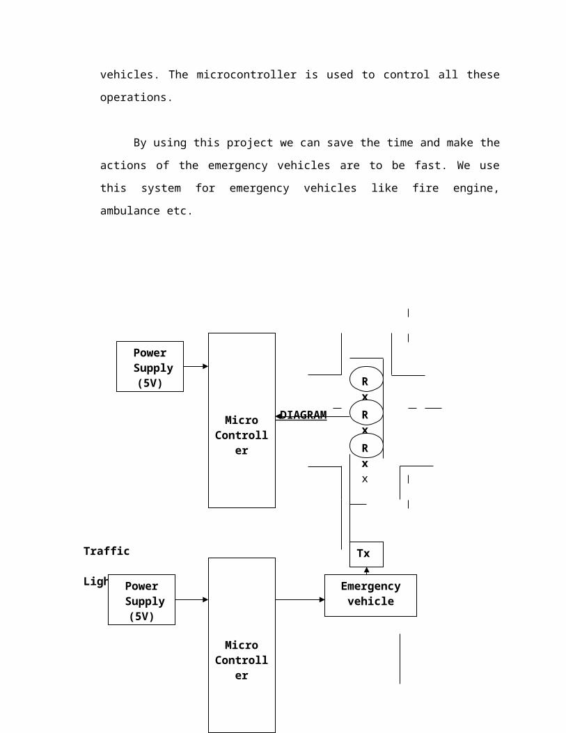
BLOCK DIAGRAM
Traffic Lights
Tx
Power Supply
(5V)
Micro Controller
RxxRxxRxx
Emergency vehicle
Micro Controller
Power Supply
(5V)
SOFTWARE TOOLS USED:
1) Keil Compiler
2) Express PCB/ORCAD
HARDWARE TOOLS:
1) Micro controller.
2) RF transmitter, RF Receiver.
3) Power Supply 5V.
1) Decoder, Encoder.
4) LCD.

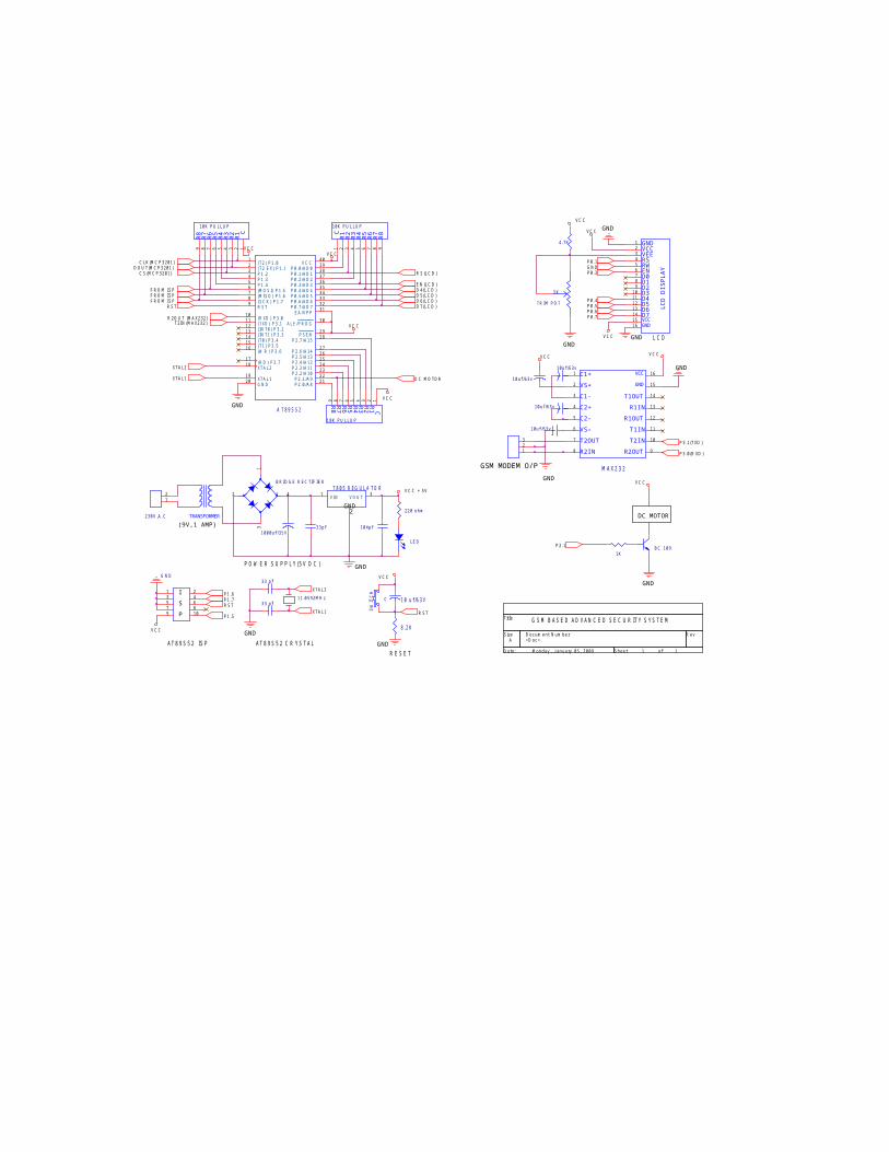
1. SCHEMATIC DIAGRAM
V C CV C C
V C C = 5 V
R ESET
1 0 u f / 6 3 v
GNDVCCVEERSRWEND0
D3D2
D4D5D6D7
LCD DISPLAY
D1
VCCGND
123456789
1 01 11 21 31 41 51 6
SW
ITC
H
1 0 4 p f
L C D
GND
<D o c >A
1 1M o n d a y , J a n u a ry 0 5 , 2 0 0 9
Tit le
S ize D o c u m e n t N u m b e r R e v
D a t e : S h e e t o f
V C C
2
AT8 9 S5 2 C R YSTAL
7805 REGULA TOR1 3
V I N V O U T
R S T
V C C
D C M O TO R
GND
G N D
1 23 45 67 89 1 0
1 1 . 0 5 9 2 M H z
3 3 p f
GND
D 5 (L C D )
C S (M C P 3 2 0 1 )
GND
R S (L C D )
1 K
1 0 u f / 6 3 v
P 2 . 1
- +
B R I D G E R E C TI F I E R
1
4
3
2
B C 1 0 9
F R O M I S PF R O M I S P
V C C
XTA L 2
R8
R7
R6
R5
R4
R3
R2
R1 C
1 0 K P U L L U P
9 8 7 6 5 4 3 2 1
1 0 u f / 6 3 v
GND
P 0 . 3
8.2K
E N (L C D )
(9V,1 AMP)
DC MOTOR
V C C
R 2 O U T (M A X2 3 2 )
V C C
XTA L 1
2 2 0 o h m
R8
R7
R6
R5
R4
R1
R2
R3 C
1 0 K P U L L U P
123456789
V C C
P 1 . 5
C1+
VS+
C1-
C2+
C2-
VS–
T2OUT
R2IN R2OUT
T2IN
T1IN
R1OUT
R1IN
T1OUT
GND
VCC
MAX2 3 2
1
2
3
4
5
6
7
8 9
1 0
1 4
1 6
1 5
1 3
1 2
1 1
GSM BASED AD VAN C ED SEC U R ITY SYSTEM
D 6 (L C D )
P 0 . 6
I
POW ER SU PPL Y(5 V D C )
3 3 p f
T2 I N (M A X2 3 2 )
D 7 (L C D )
D 4 (L C D )
P 0 . 1D O U T(M C P 3 2 0 1 )
GND
R S T
GND
3 3 p f10 uf /63VC
123
P 0 . 5
P 0 . 7
V C C
TR I M P O T
5 K
P
V C C
P 1 . 7P 1 . 6
GSM MODEM O/P
F R O M I S P
P 0 . 4
XTA L 2
GND
GND
1 0 0 0 u f / 3 5 V
GND
XTA L 1
P 3 . 1 (TXD )
R8
R7
R6
R5
R4
R1
R2
R3C
1 0 K P U L L U P
1 2 3 4 5 6 7 8 9
V C C
S
L E D
G N D
2 3 0 V , A . C
12
TRANSFORMER
R S T
A T89S52
2 0
1 81 7
2 9
3 0
1 9
3 29
1 01 11 21 31 41 51 6
4 03 93 83 73 63 53 43 3
2 8
2 72 62 52 42 32 22 1
12345678
3 1
G N D
XTA L 2(R D ) P 3 . 7
P S E N
A L E / P R O G
XTA L 1
P 0 . 7 / A D 7R S T
(R XD ) P 3 . 0(TXD ) P 3 . 1(I N T0 ) P 3 . 2(I N T1 ) P 3 . 3(T0 ) P 3 . 4(T1 ) P 3 . 5(W R ) P 3 . 6
V C CP 0 . 0 / A D 0P 0 . 1 / A D 1P 0 . 2 / A D 2P 0 . 3 / A D 3P 0 . 4 / A D 4P 0 . 5 / A D 5P 0 . 6 / A D 6
P 2 . 7 / A 1 5
P 2 . 6 / A 1 4P 2 . 5 / A 1 3P 2 . 4 / A 1 2P 2 . 3 / A 1 1P 2 . 2 / A 1 0
P 2 . 1 / A 9P 2 . 0 / A 8
(T2 ) P 1 . 0(T2 E X) P 1 . 1P 1 . 2P 1 . 3P 1 . 4(M O S I ) P 1 . 5(M I S O ) P 1 . 6(S C K ) P 1 . 7
E A / V P P
AT8 9 S5 2 ISP
C L K (M C P 3 2 0 1 )
V C C
P 3 . 0 (R XD )
GND
4 . 7 K
1 0 u f / 6 3 v
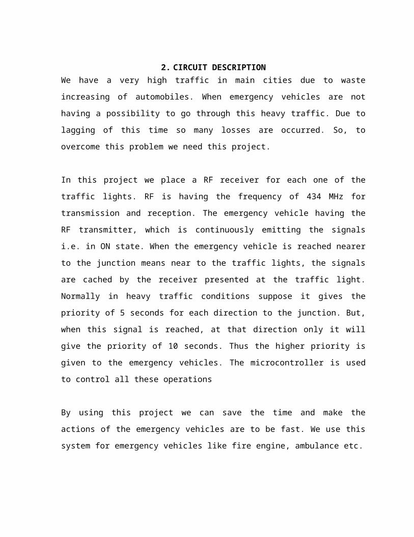
2. CIRCUIT DESCRIPTIONWe have a very high traffic in main cities due to waste increasing of automobiles. When
emergency vehicles are not having a possibility to go through this heavy traffic. Due to
lagging of this time so many losses are occurred. So, to overcome this problem we need this
project.
In this project we place a RF receiver for each one of the traffic lights. RF is having the
frequency of 434 MHz for transmission and reception. The emergency vehicle having the RF
transmitter, which is continuously emitting the signals i.e. in ON state. When the emergency
vehicle is reached nearer to the junction means near to the traffic lights, the signals are
cached by the receiver presented at the traffic light. Normally in heavy traffic conditions
suppose it gives the priority of 5 seconds for each direction to the junction. But, when this
signal is reached, at that direction only it will give the priority of 10 seconds. Thus the higher
priority is given to the emergency vehicles. The microcontroller is used to control all these
operations
By using this project we can save the time and make the actions of the emergency vehicles
are to be fast. We use this system for emergency vehicles like fire engine, ambulance etc.
3. INTRODUCTION TO EMBEDDED SYSTEMS
Embedded systems are electronic devices that incorporate microprocessors with in their implementations. The main purposes of the microprocessors are to simplify the system design and provide flexibility. Having a microprocessor in the device helps in removing the bugs, making modifications, or adding new features are only matter of rewriting the software that controls the device. Or in other words embedded computer systems are electronic systems that include a microcomputer to perform a specific dedicated application. The computer is hidden inside these products. Embedded systems are ubiquitous. Every week millions of tiny computer chips come pouring out of factories finding their way into our everyday products.
Embedded systems are self-contained programs that are embedded within a piece of hardware. Whereas a regular computer has many different applications and software that can be applied to various tasks, embedded systems are usually set to a specific task that cannot be altered without physically manipulating the circuitry. Another way to think of an embedded system is as a computer system that is created with optimal efficiency, thereby allowing it to complete specific functions as quickly as possible.
Embedded systems designers usually have a significant grasp of hardware technologies. They use specific programming languages and software to develop embedded systems and manipulate the equipment. When searching online, companies offer embedded systems development kits and other embedded systems tools for use by engineers and businesses.
Embedded systems technologies are usually fairly expensive due to the necessary development time and built in efficiencies, but they are also highly valued in specific industries. Smaller businesses may wish to hire a consultant to determine what sort of embedded systems will add value to their organization.
CHARACTERISTICS:
Two major areas of differences are cost and power consumption. Since many embedded systems are produced in tens of thousands to millions of units range, reducing cost is a major concern. Embedded systems often use a (relatively) slow processor and small memory size to minimize costs.
The slowness is not just clock speed. The whole architecture of the computer is often intentionally simplified to lower costs. For example, embedded systems often use peripherals controlled by synchronous serial interfaces, which are ten to hundreds of times slower than comparable peripherals used in PCs. Programs on an embedded system often run with real-time constraints with limited hardware resources: often there is no disk drive, operating system, keyboard or screen. A flash drive may replace rotating
media, and a small keypad and LCD screen may be used instead of a PC's keyboard and screen.
Firmware is the name for software that is embedded in hardware devices, e.g. in one or more ROM/Flash memory IC chips. Embedded systems are routinely expected to maintain 100% reliability while running continuously for long periods, sometimes measured in years. Firmware is usually developed and tested too much harsher requirements than is general-purpose software, which can usually be easily restarted if a problem occurs.
PLATFORM:
There are many different CPU architectures used in embedded designs. This in contrast to the desktop computer market which is limited to just a few competing architectures mainly the Intel/AMD x86 and the Apple/Motorola/IBM Power PC’s which are used in the Apple Macintosh. One common configuration for embedded systems is the system on a chip, an application-specific integrated circuit, for which the CPU was purchased as intellectual property to add to the IC's design.
TOOLS:
Like a typical computer programmer, embedded system designers use compilers, assemblers and debuggers to develop an embedded system. Those software tools can come from several sources:
Software companies that specialize in the embedded market Ported from the GNU software development tools. Sometimes, development tools for a personal computer can be used if the embedded processor is a close relative to a common PC processor. Embedded system designers also use a few software tools rarely used by typical computer programmers. Some designers keep a utility program to turn data files into code, so that they can include any kind of data in a program. Most designers also have utility programs to add a checksum or CRC to a program, so it can check its program data before executing it.
OPERATING SYSTEM:
They often have no operating system, or a specialized embedded operating system (often a real-time operating system), or the programmer is assigned to port one of these to the new system.
DEBUGGING:
Debugging is usually performed with an in-circuit emulator, or some type of debugger that can interrupt the micro controller’s internal microcode. The microcode interrupt lets the debugger operate in hardware in which only the CPU works. The CPU-based debugger can be used to test and debug the electronics of the computer from the viewpoint of the CPU.
Developers should insist on debugging which shows the high-level language, with breakpoints and single stepping, because these features are widely available. Also, developers should write and use simple logging facilities to debug sequences of real-time events. PC or mainframe programmers first encountering this sort of programming often become confused about design priorities and acceptable methods. Mentoring, code-reviews and ego less programming are recommended.
DESIGN OF EMBEDDED SYSTEMS:
The electronics usually uses either a microprocessor or a microcontroller. Some large or old systems use general-purpose mainframes computers or minicomputers.
START-UP:
All embedded systems have start-up code. Usually it disables interrupts, sets up the electronics, tests the computer (RAM, CPU and software), and then starts the application code. Many embedded systems recover from short-term power failures by restarting (without recent self-tests). Restart times under a tenth of a second are common.
Many designers have found one of more hardware plus software-controlled LED’s useful to indicate errors during development (and in some instances, after product release, to produce troubleshooting diagnostics). A common scheme is to have the electronics turn off the LED(s) at reset, whereupon the software turns it on at the first opportunity, to prove that the hardware and start-up software have performed their job so far. After that, the software blinks the LED(s) or sets up light patterns during normal operation, to indicate program execution progress and/or errors. This serves to reassure most technicians/engineers and some users.
THE CONTROL LOOP:
In this design, the software has a loop. The loop calls subroutines. Each subroutine manages a part of the hardware or software. Interrupts generally set flags, or update counters that are read by the rest of the software. A simple API disables and enables interrupts. Done right, it handles nested calls in nested subroutines, and restores the preceding interrupt state in the outermost enable. This is one of the simplest methods of creating an exocrine.
Typically, there's some sort of subroutine in the loop to manage a list of software timers, using a periodic real time interrupt. When a timer expires, an associated subroutine is run, or flag is set. Any expected hardware event should be backed-up with a software timer. Hardware events fail about once in a trillion times.
State machines may be implemented with a function-pointer per state-machine (in C++, C or assembly, anyway). A change of state stores a different function into the pointer. The function pointer is executed every time the loop runs.
Many designers recommend reading each IO device once per loop, and storing the result so the logic acts on consistent values. Many designers prefer to design their state machines to check only one or two things per state. Usually this is a hardware event, and a software timer. Designers recommend that hierarchical state machines should run the lower-level state machines before the higher, so the higher run with accurate information.
Complex functions like internal combustion controls are often handled with multi-dimensional tables. Instead of complex calculations, the code looks up the values. The software can interpolate between entries, to keep the tables small and cheap.
One major disadvantage of this system is that it does not guarantee a time to respond to any particular hardware event. Careful coding can easily assure that nothing disables interrupts for long. Thus interrupt code can run at very precise timings. Another major weakness of this system is that it can become complex to add new features. Algorithms that take a long time to run must be carefully broken down so only a little piece gets done each time through the main loop.
This system's strength is its simplicity, and on small pieces of software the loop is usually so fast that nobody cares that it is not predictable. Another advantage is that this system guarantees that the software will run. There is no mysterious operating system to blame for bad behavior.
USER INTERFACES:Interface designers at PARC, Apple Computer, Boeing and HP minimize the
number of types of user actions. For example, use two buttons (the absolute minimum) to control a menu system (just to be clear, one button should be "next menu entry" the other button should be "select this menu entry"). A touch-screen or screen-edge buttons also minimize the types of user actions.
Another basic trick is to minimize and simplify the type of output. Designs should consider using a status light for each interface plug, or failure condition, to tell what failed. A cheap variation is to have two light bars with a printed matrix of errors that they select- the user can glue on the labels for the language that she speaks.
For example, Boeing's standard test interface is a button and some lights. When you press the button, all the lights turn on. When you release the button, the lights with failures stay on. The labels are in Basic English.
Designers use colors. Red defines the users can get hurt- think of blood. Yellow defines something might be wrong. Green defines everything's OK.
Another essential trick is to make any modes absolutely clear on the user's display. If an interface has modes, they must be reversible in an obvious way. Most designers prefer the display to respond to the user. The display should change immediately after a user action. If the machine is going to do anything, it should start within 7 seconds, or give progress reports.
One of the most successful general-purpose screen-based interfaces is the two menu buttons and a line of text in the user's native language. It's used in pagers, medium-priced printers, network switches, and other medium-priced situations that require complex behavior from users. When there's text, there are languages. The default language should be the one most widely understood.
INTRODUCTION TO MICROCONTROLLER
Microcontrollers as the name suggests are small controllers. They are like single chip computers that are often embedded into other systems to function as processing/controlling unit. For example the remote control you are using probably has microcontrollers inside that do decoding and other controlling functions. They are also used in automobiles, washing machines, microwave ovens, toys ... etc, where automation is needed.
Micro-controllers are useful to the extent that they communicate with other devices, such as sensors, motors, switches, keypads, displays, memory and even other micro-controllers. Many interface methods have been developed over the years to solve the complex problem of balancing circuit design criteria such as features, cost, size, weight, power consumption, reliability, availability, manufacturability. Many microcontroller designs typically mix multiple interfacing methods. In a very simplistic form, a micro-controller system can be viewed as a system that reads from (monitors) inputs, performs processing and writes to (controls) outputs.
Embedded system means the processor is embedded into the required application. An embedded product uses a microprocessor or microcontroller to do one task only. In an embedded system, there is only one application software that is typically burned into ROM. Example: printer, keyboard, video game player
Microprocessor - A single chip that contains the CPU or most of the computerMicrocontroller - A single chip used to control other devices
Microcontroller differs from a microprocessor in many ways. First and the most important is its functionality. In order for a microprocessor to be used, other components such as memory, or components for receiving and sending data must be added to it. In short that means that microprocessor is the very heart of the computer. On the other hand, microcontroller is designed to be all of that in one. No other external components are needed for its application because all necessary peripherals are already built into it. Thus, we save the time and space needed to construct devices.
MICROPROCESSOR VS MICROCONTROLLER:
Microprocessor: CPU is stand-alone, RAM, ROM, I/O, timer are separate Designer can decide on the amount of ROM, RAM and I/O ports. expensive versatility general-purpose
Microcontroller:• CPU, RAM, ROM, I/O and timer are all on a single chip• fix amount of on-chip ROM, RAM, I/O ports• for applications in which cost, power and space are critical• single-purpose
MICROCONTROLLER 89S52
FEATURES:
8K Bytes of In-System Reprogrammable Flash Memory Endurance: 1,000 Write/Erase Cycles Fully Static Operation: 0 Hz to 24 MHz 256 x 8-bit Internal RAM 32 Programmable I/O Lines Three 16-bit Timer/Counters Eight Interrupt Sources Programmable Serial Channel Low-power Idle and Power-down ModesDESCRIPTION:The AT89C52 is a low-power, high-performance CMOS 8-bit microcomputer with 8Kbytes of Flash programmable and erasable read only memory (PEROM). The on-chip Flash allows the program memory to be reprogrammed in-system or by a conventional nonvolatile memory programmer. By combining a versatile 8-bit CPU with Flash on a monolithic chip, the Atmel AT89C52 is a powerful microcomputer, which provides a highly flexible and cost-effective solution to many embedded control applications.
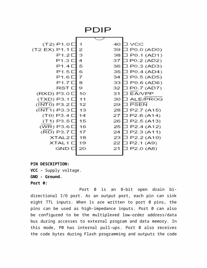
PIN DIAGRAM - AT89S52:
PIN DESCRIPTION:VCC - Supply voltage.GND - Ground.Port 0: Port 0 is an 8-bit open drain bi-directional I/O port. As an output port, each pin can sink eight TTL inputs. When 1s are written to port 0 pins, the pins can be used as high-impedance inputs. Port 0 can also be configured to be the multiplexed low-order address/data bus during accesses to external program and data memory. In this mode, P0 has internal pull-ups. Port 0 also receives the code bytes during Flash programming and outputs the code bytes during program verification. External pull-ups are required during program verification.
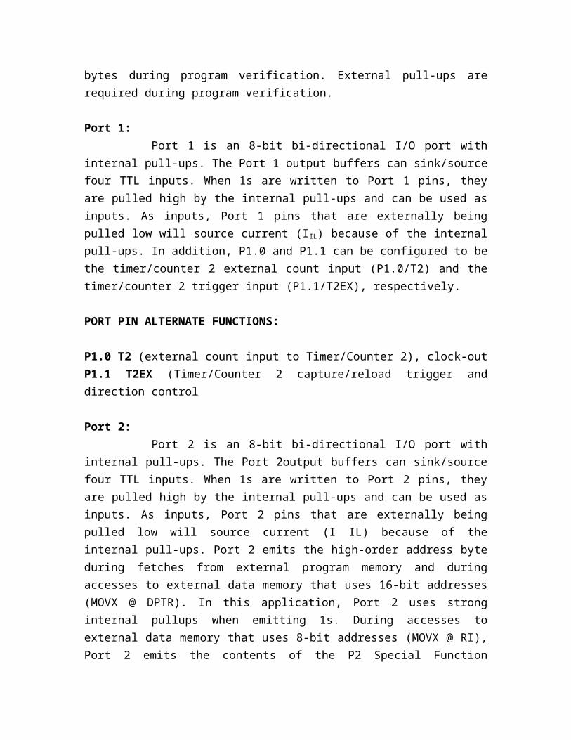
Port 1:Port 1 is an 8-bit bi-directional I/O port with internal pull-ups. The Port 1
output buffers can sink/source four TTL inputs. When 1s are written to Port 1 pins, they
are pulled high by the internal pull-ups and can be used as inputs. As inputs, Port 1 pins that are externally being pulled low will source current (I IL) because of the internal pull-ups. In addition, P1.0 and P1.1 can be configured to be the timer/counter 2 external count input (P1.0/T2) and the timer/counter 2 trigger input (P1.1/T2EX), respectively.
PORT PIN ALTERNATE FUNCTIONS:
P1.0 T2 (external count input to Timer/Counter 2), clock-outP1.1 T2EX (Timer/Counter 2 capture/reload trigger and direction control
Port 2:Port 2 is an 8-bit bi-directional I/O port with internal pull-ups. The Port
2output buffers can sink/source four TTL inputs. When 1s are written to Port 2 pins, they are pulled high by the internal pull-ups and can be used as inputs. As inputs, Port 2 pins that are externally being pulled low will source current (I IL) because of the internal pull-ups. Port 2 emits the high-order address byte during fetches from external program memory and during accesses to external data memory that uses 16-bit addresses (MOVX @ DPTR). In this application, Port 2 uses strong internal pullups when emitting 1s. During accesses to external data memory that uses 8-bit addresses (MOVX @ RI), Port 2 emits the contents of the P2 Special Function Register. Port 2 also receives the high-order address bits and some control signals during Flash programming and verification.
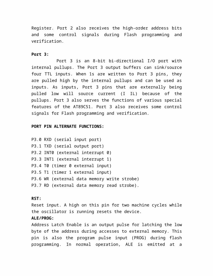
Port 3:Port 3 is an 8-bit bi-directional I/O port with internal pullups. The Port 3
output buffers can sink/source four TTL inputs. When 1s are written to Port 3 pins, they are pulled high by the internal pullups and can be used as inputs. As inputs, Port 3 pins that are externally being pulled low will source current (I IL) because of the pullups. Port 3 also serves the functions of various special features of the AT89C51. Port 3 also receives some control signals for Flash programming and verification.
PORT PIN ALTERNATE FUNCTIONS:
P3.0 RXD (serial input port)P3.1 TXD (serial output port)P3.2 INT0 (external interrupt 0)P3.3 INT1 (external interrupt 1)P3.4 T0 (timer 0 external input)P3.5 T1 (timer 1 external input)P3.6 WR (external data memory write strobe)P3.7 RD (external data memory read strobe).
RST:Reset input. A high on this pin for two machine cycles while the oscillator is running resets the device.ALE/PROG:Address Latch Enable is an output pulse for latching the low byte of the address during accesses to external memory. This pin is also the program pulse input (PROG) during flash programming. In normal operation, ALE is emitted at a constant rate of 1/6 the oscillator frequency and may be used for external timing or clocking purposes. However, that one ALE pulse is skipped during each access to external data memory. If desired, ALE operation can be disabled by setting bit 0 of SFR location 8EH. With the bit set, ALE is active only during a MOVX or MOVC instruction. Otherwise, the pin is weakly pulled high. Setting the ALE-disable bit has no effect if the microcontroller is in external execution mode.
PSEN:Program Store Enable is the read strobe to external program memory. When the AT89C52 is executing code from external program memory, PSEN is activated twice each machine cycle, except that two PSEN activations are skipped during each access to external data memory. EA/VPP:External Access Enable (EA) must be strapped to GND in order to enable the device to fetch code from external pro-gram memory locations starting at 0000H up to FFFFH. However, if lock bit 1 is programmed, EA will be internally latched on reset. EA should be strapped to VCC for internal program executions. This pin also receives the 12V programming enable voltage (VPP) during Flash programming when 12V programming is selected.XTAL1: input to the inverting oscillator amplifier and input to the internal clock operating circuit.XTAL2:It is an output from the inverting oscillator amplifier
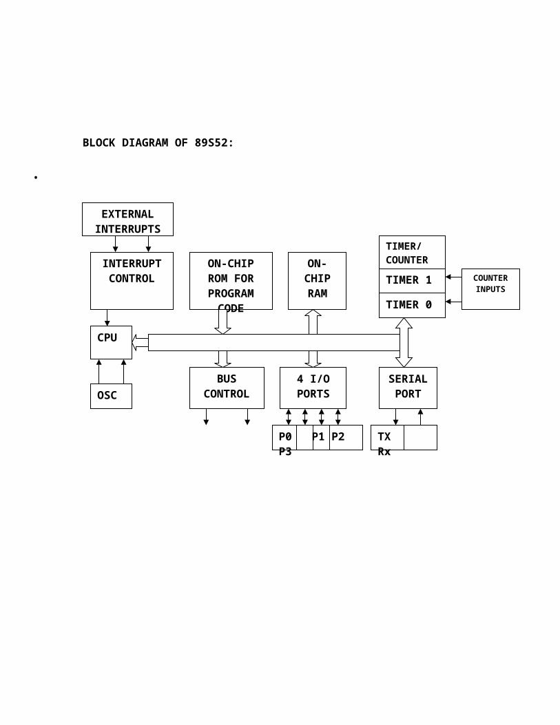
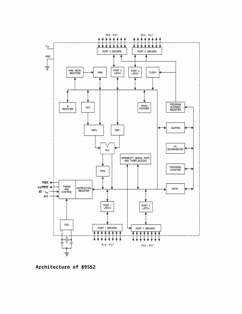
BLOCK DIAGRAM OF 89S52:
•
ARCHITECHTURE OF 8052 MICROCONTROLLER:
INTERRUPT CONTROL
ON-CHIP ROM FOR PROGRAM
CODE
ON-CHIP RAM
TIMER/COUNTER
TIMER 1
TIMER 0
OSC
BUS CONTROL
4 I/O PORTS
SERIAL PORT
CPU
EXTERNAL INTERRUPTS
COUNTER INPUTS
P0 P1 P2 P3 TX Rx
Architecture of 89S52
OSCILLATOR CHARACTERISTICS:XTAL1 and XTAL2 are the input and output, respectively, of an inverting
amplifier, which can be configured for use as an on-chip oscillator. Either a quartz crystal or ceramic resonator may be used. To drive the device from an external clock source, XTAL2 should be left unconnected while XTAL1 is driven. There are no requirements on the duty cycle of the external clock signal, since the input to the internal clocking circuitry is through a divide-by-two flip-flop, but minimum and maximum voltage high and low time specifications must be observed.
IDLE MODE:
In idle mode, the CPU puts itself to sleep while all the on-chip peripherals remain active. The mode is invoked by software. The content of the on-chip RAM and all the special functions registers remain unchanged during this mode. The idle mode can be terminated by any enabled interrupt or by a hardware reset. It should be noted that when idle is terminated by a hardware reset, the device normally resumes program execution, from where it left off, up to two machine cycles before the internal reset algorithm takes control. On-chip hardware inhibits access to internal RAM in this event, but access to the port pins is not inhibited. To eliminate the possibility of an unexpected write to a port pin when Idle is terminated by reset, the instruction following the one that invokes Idle should not be one that writes to a port pin or to external memory.
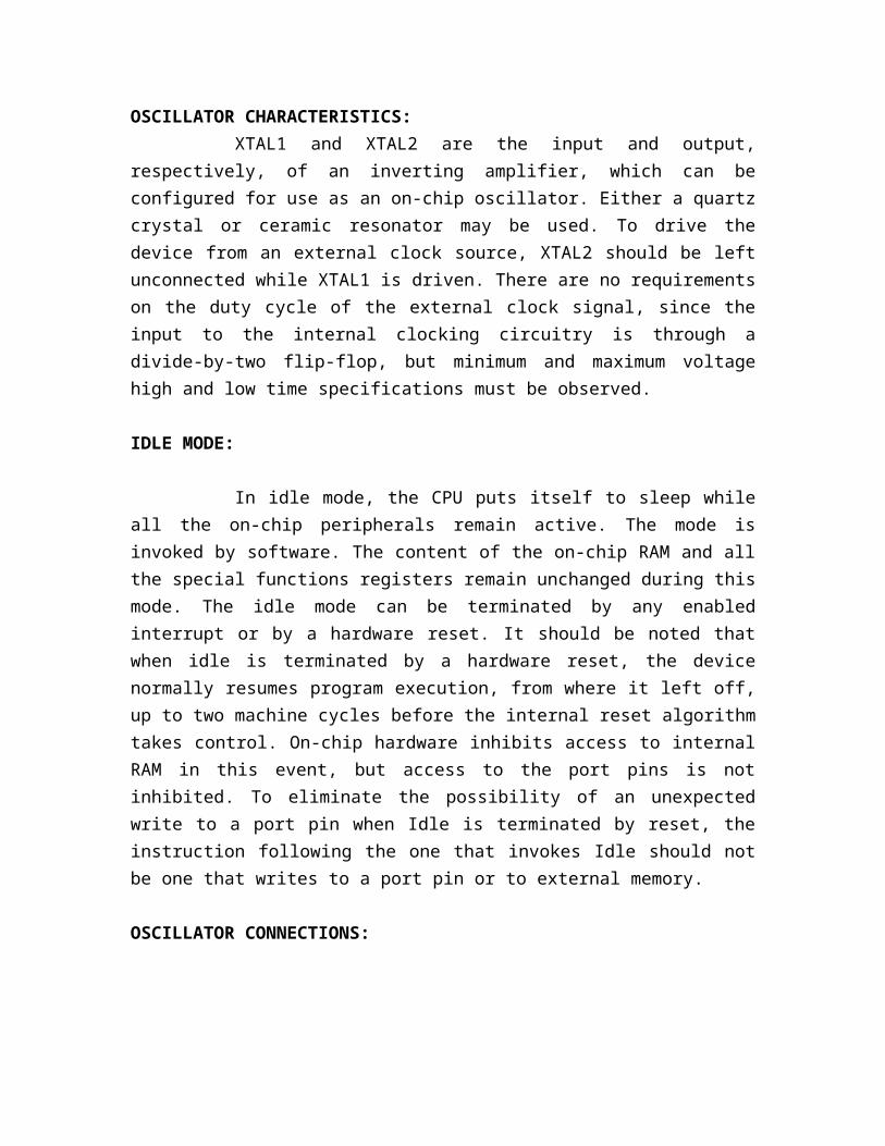
OSCILLATOR CONNECTIONS:
Oscillator Connections
Note: C1, C2 = 30 pF ± 10 pF for Crystals = 40 pF ± 10 pF for Ceramic Resonators
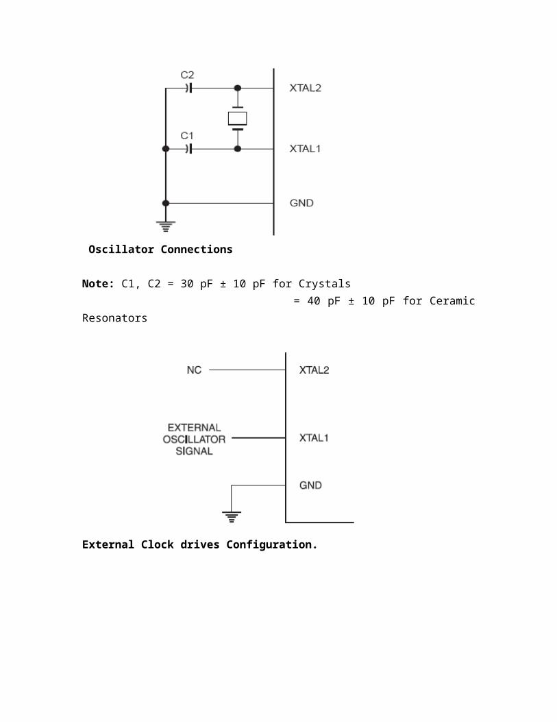
External Clock drives Configuration.
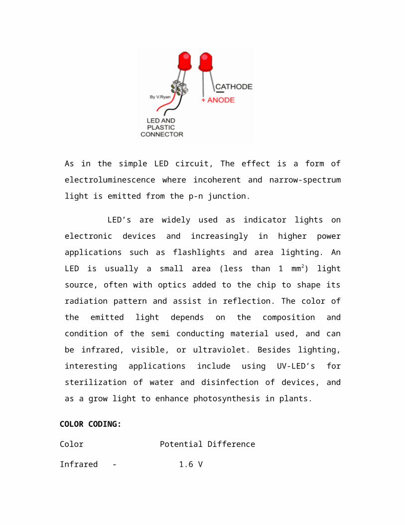
LIGHT EMITTING DIODE (LED)
A light-emitting diode (LED) is a semiconductor diode that emits
incoherent narrow spectrum light when electrically biased in the forward direction of the
pn-junction, as in the common LED circuit. This effect is a form of electroluminescence.
While sending a message in the form of bits such as 1,the data is sent to
the receiver side correspondingly the LED glows representing the data is being received
simultaneously when we send 8 as a data the LED gets off .
As in the simple LED circuit, The effect is a form of electroluminescence where
incoherent and narrow-spectrum light is emitted from the p-n junction.
LED’s are widely used as indicator lights on electronic devices and
increasingly in higher power applications such as flashlights and area lighting. An
LED is usually a small area (less than 1 mm2) light source, often with optics added to
the chip to shape its radiation pattern and assist in reflection. The color of the emitted
light depends on the composition and condition of the semi conducting material used,
and can be infrared, visible, or ultraviolet. Besides lighting, interesting applications
include using UV-LED’s for sterilization of water and disinfection of devices, and as a
grow light to enhance photosynthesis in plants.
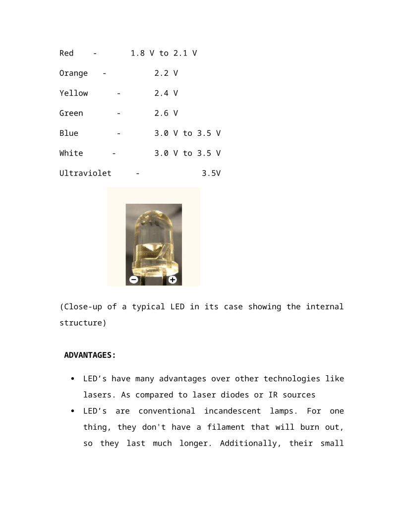
COLOR CODING:
Color Potential Difference
Infrared - 1.6 V
Red - 1.8 V to 2.1 V
Orange - 2.2 V
Yellow - 2.4 V
Green - 2.6 V
Blue - 3.0 V to 3.5 V
White - 3.0 V to 3.5 V
Ultraviolet - 3.5V
(Close-up of a typical LED in its case showing the internal structure)
ADVANTAGES:
LED’s have many advantages over other technologies like lasers. As compared to
laser diodes or IR sources
LED’s are conventional incandescent lamps. For one thing, they don't have a
filament that will burn out, so they last much longer. Additionally, their small
plastic bulb makes them a lot more durable. They also fit more easily into modern
electronic circuits.
The main advantage is efficiency. In conventional incandescent bulbs, the light-
production process involves generating a lot of heat (the filament must be
warmed). Unless you're using the lamp as a heater, because a huge portion of the
available electricity isn't going toward producing visible light.
LED’s generate very little heat. A much higher percentage of the electrical power
is going directly for generating light, which cuts down the electricity demands
considerably.
LED’s offer advantages such as low cost and long service life. Moreover LED’s
have very low power consumption and are easy to maintain.
DISADVANTAGES OF LEDS:
LED’s performance largely depends on the ambient temperature of the operating
environment.
LED’s must be supplied with the correct current.
LED’s do not approximate a "point source" of light, so cannot be used in
applications needing a highly collimated beam.
But the disadvantages are quite negligible as the negative properties of
LED’s do not apply and the advantages far exceed the limitations.

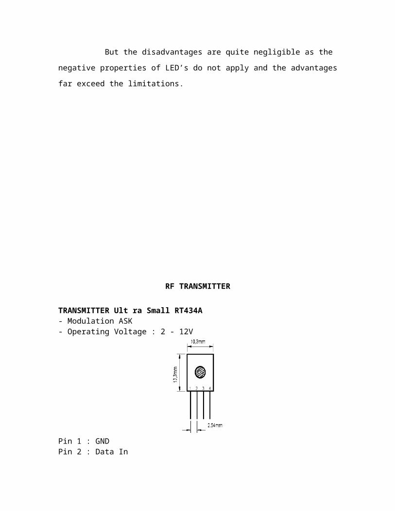
RF TRANSMITTER
TRANSMITTER Ult ra Small RT434A- Modulation ASK- Operating Voltage : 2 - 12V
Pin 1 : GNDPin 2 : Data InPin 3 : VccPin 4 : Antenna ( RF Output )
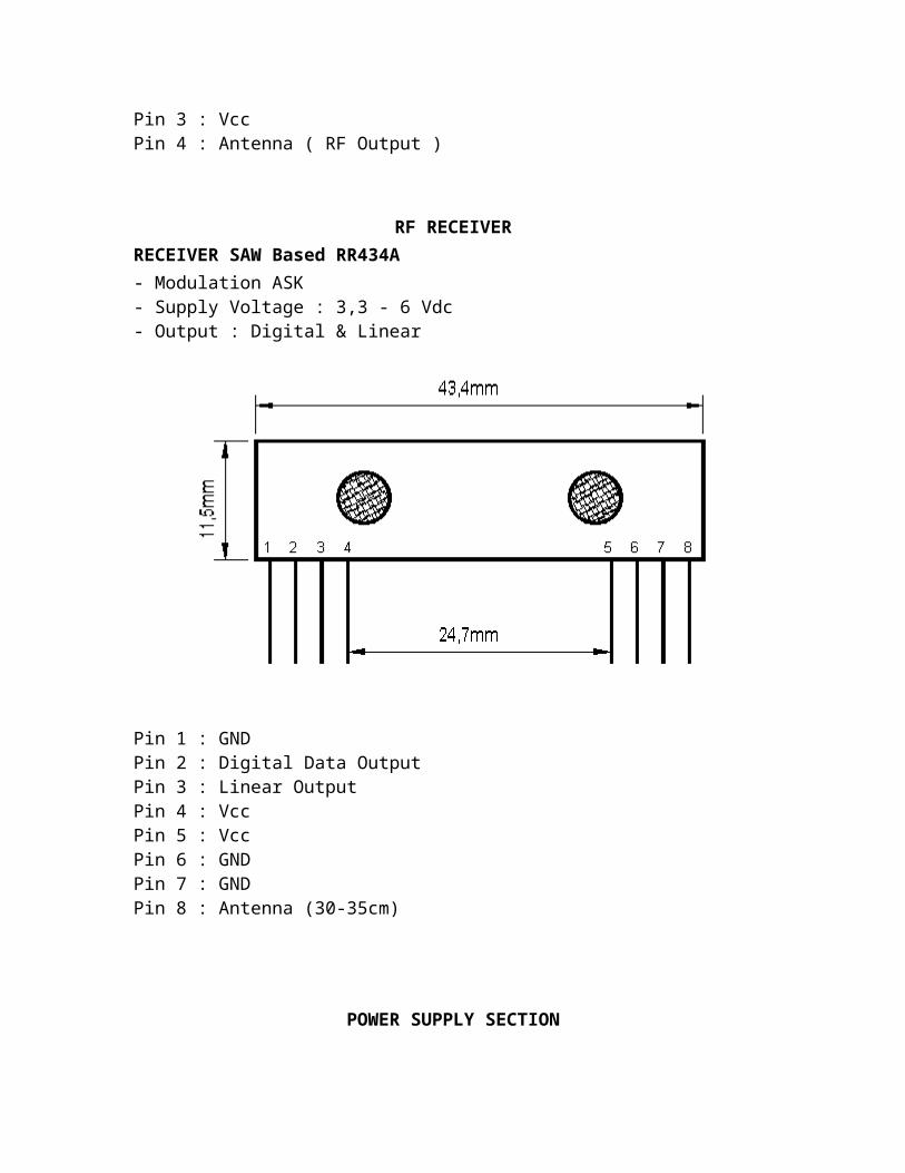
RF RECEIVERRECEIVER SAW Based RR434A- Modulation ASK- Supply Voltage : 3,3 - 6 Vdc- Output : Digital & Linear
Pin 1 : GNDPin 2 : Digital Data OutputPin 3 : Linear OutputPin 4 : VccPin 5 : VccPin 6 : GNDPin 7 : GNDPin 8 : Antenna (30-35cm)
POWER SUPPLY SECTION
In-order to work with any components basic requirement is power supply. In this section there is a requirement of two different voltage levels.Those are
1) 5V DC power supply.2) 9V DC power supply.
Now the aim is to design the power supply section which converts 230V AC in to 5V DC. Since 230V AC is too high to reduce it to directly 5V DC, therefore we need a step-down transformer that reduces the line voltage to certain voltage that will help us to convert it in to a 5V DC. Considering the efficiency factor of the bridge rectifier, we came to a conclusion to choose a transformer, whose secondary voltage is 3 to 4 V higher than the required voltage i.e. 5V. For this application 0-9V transformers is used, since it is easily available in the market.The output of the transformer is 9V AC; it feed to rectifier that converts AC to pulsating DC. As we all know that there are 3 kind of rectifiers that is
1) half wave2) Full wave and3) Bridge rectifier
Here we short listed to use Bridge rectifier, because half wave rectifier has we less in efficiency. Even though the efficiency of full wave and bridge rectifier are the same, since there is no requirement for any negative voltage for our application, we gone with bridge rectifier.
Since the output voltage of the rectifier is pulsating DC, in order to convert it into pure DC we use a high value (1000UF/1500UF) of capacitor in parallel that acts as a filter.
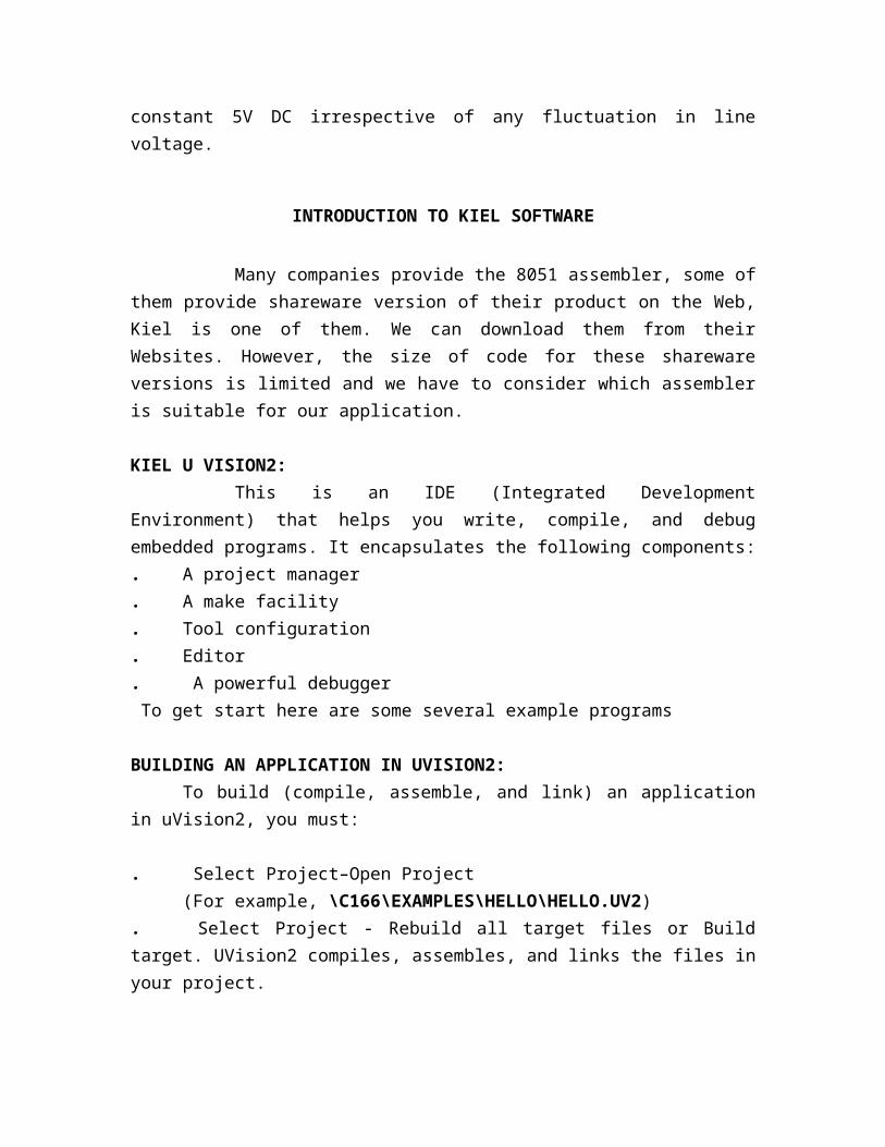
The most easy way to regulate this voltage is by using a 7805 voltage regulator, whose output voltage is constant 5V DC irrespective of any fluctuation in line voltage.
INTRODUCTION TO KIEL SOFTWARE
Many companies provide the 8051 assembler, some of them provide shareware version of their product on the Web, Kiel is one of them. We can download them from their Websites. However, the size of code for these shareware versions is limited and we have to consider which assembler is suitable for our application.
KIEL U VISION2:This is an IDE (Integrated Development Environment) that helps you
write, compile, and debug embedded programs. It encapsulates the following components:. A project manager. A make facility. Tool configuration. Editor. A powerful debugger To get start here are some several example programs
BUILDING AN APPLICATION IN UVISION2:To build (compile, assemble, and link) an application in uVision2, you must:
. Select Project–Open Project(For example, \C166\EXAMPLES\HELLO\HELLO.UV2)
. Select Project - Rebuild all target files or Build target. UVision2 compiles, assembles, and links the files in your project.
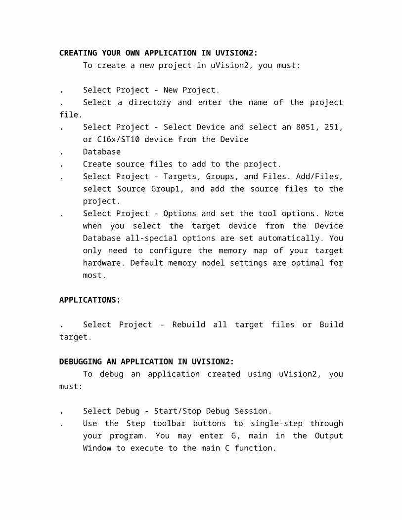
CREATING YOUR OWN APPLICATION IN UVISION2:To create a new project in uVision2, you must:
. Select Project - New Project.
. Select a directory and enter the name of the project file.
. Select Project - Select Device and select an 8051, 251, or C16x/ST10 device from the Device
. Database
. Create source files to add to the project.
. Select Project - Targets, Groups, and Files. Add/Files, select Source Group1, and add the source files to the project.
. Select Project - Options and set the tool options. Note when you select the target device from the Device Database all-special options are set automatically. You only need to configure the memory map of your target hardware. Default memory model settings are optimal for most.
APPLICATIONS:
. Select Project - Rebuild all target files or Build target.
DEBUGGING AN APPLICATION IN UVISION2:To debug an application created using uVision2, you must:
. Select Debug - Start/Stop Debug Session.
. Use the Step toolbar buttons to single-step through your program. You may enter G, main in the Output Window to execute to the main C function.
. Open the Serial Window using the Serial #1 button on the toolbar.
. Debug your program using standard options like Step, Go, Break, and so on.
LIMITATIONS OF EVALUATION SOFTWARE:The following limitations apply to the evaluation versions of the C51, C251, or
C166 tool chains. C51 Evaluation Software Limitations:
. The compiler, assembler, linker, and debugger are limited to 2 Kbytes of object code but source Code may be any size. Programs that generate more than 2 Kbytes of object code will not compile, assemble, or link the startup code generated includes LJMP's and cannot be used in single-chip devices supporting Less than 2 Kbytes of program space like the Philips 750/751/752.
. The debugger supports files that are 2 Kbytes and smaller.
. Programs begin at offset 0x0800 and cannot be programmed into single-chip devices.. No hardware support is available for multiple DPTR registers.. No support is available for user libraries or floating-point arithmetic.
EVALUATION SOFTWARE:. Code-Banking Linker/Locator . Library Manager.. RTX-51 Tiny Real-Time Operating System
PERIPHERAL SIMULATION:
The u vision2 debugger provides complete simulation for the CPU and on chip peripherals of most embedded devices. To discover which peripherals of a device are supported, in u vision2. Select the Simulated Peripherals item from the Help menu. You may also use the web-based device database. We are constantly adding new devices and simulation support for on-chip peripherals so be sure to check Device Database often.
CODE:#include<reg52.h>
#include<intrins.h>
void delay_ms(unsigned int i);
void send(unsigned char c);
void integer_send(a);
void print(char *str);
sbit g1 =P2^5;
sbit y1 =P2^4;
sbit r1 =P2^3;
sbit g2 =P0^4;
sbit y2 =P0^5;
sbit r2=P0^6;
sbit g3=P2^6;
sbit y3=P2^7;
sbit r3=P0^7;
sbit g4=P2^0;
sbit y4=P2^1;
sbit r4=P2^2;
unsigned char a,b,c,d;
void compare();
unsigned int route_1();
unsigned int route_2();
unsigned int route_3();
unsigned int route_4();
void display();
void fun_a();
void fun_b();
void fun_c();
void fun_d();
void fun_y() ;
unsigned int z;
unsigned int m=0;
bit flag=0;
void serial_intr(void) interrupt 4
{
if(TI == 1)
{
TI = 0;
flag = 1;
}
if(RI==1)
{
}
}
void main()
{
TMOD = 0x20;
SCON = 0x50;
TH1 = 0xFD;
TR1 = 1;
IE = 0x90;
TH0=0x00;
TL0=0x00;
print("TRAFFIC SIGNALS\r\n");
/*fun_a();
fun_b();
fun_c();
fun_d();
*/
while(1)
{
display();
}
}
void fun_d( )
{
print("\r\nEAST\r\n");
y1=1;
r2=0;
r3=0;
r4=0;
y1=1;
g1=0;
r1=1;
delay_ms(1000);
g1=1;
y1=0;
r2=1;
y2=0;
r1=1;
delay_ms(1000);
g1=1;
y1=1;
r1=0;
}
void fun_b( )
{
print("\r\nWEST\r\n");
y2=1;
r1=0;
r3=0;
r4=0;
g2=0;
y2=1;
r2=1;
delay_ms(1000);
g2=1;
y2=0;
r3=1;
y3=0;
//y3=1;
r2=1;
delay_ms(1000);
g2=1;
y2=1;
r2=0;
}
void fun_c( )
{
print("\r\nNORTH\r\n");
r1=0;
r2=0;
r4=0;
g3=0;
y3=1;
r3=1;
delay_ms(1000);
g3=1;
y3=0;
r4=1;
y4=0;
//y1=1;
r3=1;
delay_ms(1000);
g3=1;
y3=1;
r3=0;
}
void fun_a( )
{

print("\r\nSOUTH\r\n");
r1=0;
r2=0;
r3=0;
g4=0;
y4=1;
r4=1;
delay_ms(1000);
g4=1;
y4=0;
r1=1;
y1=0;
//y2=1;
r4=1;
delay_ms(1000);
g4=1;
y4=1;
r4=0;
}
/*void fun_y()
{
r1=1;
r2=1;
r3=1;
r4=1;
y1=0;
y2=0;
y3=0;
y4=0;
delay_ms(1000);
y1=1;
y2=1;
y3=1;
y4=1;
delay_ms(1000);
}*/
void delay_ms(unsigned int i)
{
unsigned int j;
while(i-->0)
{
for(j=0;j<250;j++)
{;}
}
}
REFERENCE
TEXT BOOKS REFERED:
1. “The 8051 Microcontroller and Embedded Systems” by Muhammad Ali Mazidi
and Janice Gillispie Mazidi, Pearson Education.
2. 8051 Microcontroller Architecture, programming and application by KENNETH JAYALA
3. ATMEL 89s52 Data sheets
4. Hand book for Digital IC’s from Analogic Devices
WEBSITES VIEWED:
www.atmel.com
www.beyondlogic.org
www.dallassemiconductors.com
www.maxim-ic.com
www.alldatasheets.com
www.howstuffworks.com