track roller linear guidance - ahr international · track roller linear guidance systems with...
TRANSCRIPT


CORPORATE OFFICES308 SPRINGHILL FARM ROADFORT MILL, SOUTH CAROLINA 29715
TELEPHONE (803)548-8500FAX (803)548-8599
DISTRIBUTOR CUSTOMER SERVICETOLL FREE 800-523-6572FAX (803)548-8594
LINEAR CUSTOMER SERVICETOLL FREE 800-462-3399FAX (215)781-9830
This product section has been excerpted from our fullProduct Reference Guide to reduce download time.Our complete Product Reference Guide is available inprint and on CD-ROM. To receive the full version,please contact your nearest INA Sales Office listed onthe last page of this file.
TRACK ROLLERLINEAR GUIDANCESYSTEMS

FOREWORD
ABMA American Bearing Manufacturers AssociationASTM American Society Of Testing And MaterialsDIN Deutsches Institut für Normung e.V.ISO International Standards Organization
Elges, Andrews and Corrotect are registered trademarks ofINA USA Corporation.Permaglide is a registered trademark and a product ofKOLBENSCHMIDT AG, Neckarsulm, also produced inGreensburg, Indiana, USA.All other products and company names are trademarks or registeredtrademarks of their respective companies.
ALL RIGHTS RESERVED
INA USA Corporation308 Springhill Farm RoadFort Mill, SC 29715
Reproduction of this publication in whole or in part without the expresswritten consent of INA USA Corporation is prohibited.
Although every effort has been made to ensure the accuracy of theinformation contained in this catalog, INA shall not be liable for anyomissions or errors. Purchasers should consult their own testing todetermine the suitability of any product for a particular purpose. In noevent shall INA be liable for any claims for damages based upon breachof warranty, breach of contract, negligence, strict liability in tort, or anyother legal theory.
INA USA Corporation reserves the right to make changes / revisions tospecifications contained herein without notice.
� Copyright 1999, 2000 INA USA Corporation
This publication was designed to serve as a quick refer-ence to the standard product series offered by INA USACorporation (INA) for its domestic market. The guide pro-vides a current overview of INA products, including basicenvelope dimensions and capacities, in one publication –it is not an engineering design guide intended to replaceINA engineering catalogs. Consequently, the metric andinch conversions are listed to 3 decimal places for easyreference and rapid identification of correct replacementpart(s), not 4 decimal places as necessary for qualitycontrol purposes.
This publication can be used to narrow the choices be-tween the many different INA product lines and series fornew designs. Detailed engineering information for newdesigns can be found in our traditional catalogs or bycontacting the INA Engineering Department.
A significant portion of INA sales are special productionsizes. The identification of those parts is sometimes diffi-cult since a comprehensive listing is beyond the intent ofthis publication. Special part numbers take as many dif-ferent forms as the series listed here, but the basic sys-tem is to use sequential numbers for each new design.Usually the prefix is F or FC but can include VH, INA orthe bearing type such as NA. INA maintains a technicalhelp desk to identify sizes not known or to match compet-itors’ parts.
The toll free 800 numbers listed will give you access toINA Customer Service representatives. These represen-tatives can tap into INA Worldwide resources to providethe bearings you need.
Storage LifeLubricants age naturally due to environmental influences.It is therefore the user’s responsibility to follow the direc-tions given by the lubricant manufacturer.
The greases used in INA rolling bearings have a mineraloil base and experience shows that they can be stored forup to 3 years without deteriorating providing the followingimportant conditions are met.
�Closed storage room�Temperature between 0�C and 40�C�Relative atmospheric humidity 65% or less�Security from chemical agents
(vapors, gases, fluids)�Sealed rolling bearings
The frictional torque can be considerably higher after lin-ger storage periods than in freshly greased bearings andthe lubricity of the grease can also have deteriorated.
INA bearings have many optional features available in-cluding:
� ISO series of bearings generally include the stan-dard clearance options CN, C2, C3 and C4.
� ISO bearing series include PN, P6 and P5 precisionclasses.
� Corrotect� plating is available for most bearing de-signs. Corrotect is a patented process for zinc–ironand zinc–iron–cobalt plating in a thin layer which canbe applied to standard components. The protectionexceeds stainless steel and the cost is half. Addsuffix RR.
� All sealed bearings are supplied pregreased. Inmost cases the standard lubricant is Shell Alvania 2or equivalent. Other greases are available, some atextra cost.
� Unsealed bearings may not be greased whenshipped.
�Speed limits as published, are based on oil lubrica-tion for open bearings or grease lubrication forsealed bearings. The speed limits are calculatedbased on a nominal load and heat balance equation.Higher speeds may be allowed depending on theapplication.
� Dynamic capacities are published based on INAstandard usage of ISO and ABMA formulas. Newlife theory threshold values are published in otherINA publications.
� Life calculations and evaluations can be made fromINA engineering based catalogs which are availablefrom your INA Sales Representative.
� Other features are available based on current pro-duction volumes including heat stabilization of therings, matched bearing sets, with oil holes andgrooves, etc.

Track Roller Linear GuidanceSystems With Hollo w SectionCarriageLFCL SERIESAnd GuidewaysLFS,LFS..C,LFS..CE,LFS..N SERIES
For details on part numbers, descriptive suffixes and various technical references, please refer to front of this section.For engineering or technical information contact your local sales representative or call Distributor Sales (800)523-6572 or Linear Sales (800)462-3399.
�
��
��
��
��
��
�
�
��
�
�
������ �� ������
�� �LFCL with LFS, LFS..C
486
DIMENSION TABLE · Dimensions in mm
CARRIAGE 1) MASS CONTAINS TRACK ROLLER
GUIDEWAYS MASS DIMENSIONS MOUNTINGDIMENSIONSTRACK ROLLER
CARRIAGE GUIDEWAY
H A C h a L2) A1 A2 A3
�g �g/m
LFCL 25 440 LFR 50/8 KDD LFS 25 1,100 32 80 110 15 25 2,000 47 47 69
LFCL 25 440 LFR 50/8 KDD LFS 25 N 1,000 32 80 110 15 25 2,000 47 47 69
LFCL 42 1,000 LFR 5201 KDD LFS 42 C1) 2,200 39 116 150 20 42 8,000 73 73 98.5
LFCL 42 1,000 LFR 5201 KDD LFS 42 CE1) 2,200 39 116 150 20 42 8,000 73 73 98.5
LFCL 867) 2,200 LFR 5301 KDD LFS 86 C1) 4,400 59 190 235 34 86 8,000 124 124 151.5
Corrosion-resistant executions: LFCL..VA, LFS..VA. Guideway without holes: LFS..OL.1) The shape of the hollow sections is dependent on the size.2) Maximum length of single-piece guideways,
longer guideways are supplied as multi-piece guideways and are marked accordingly.3) Dimensions C5 and C6 are dependent on the guideway length L.4) For screws to DIN 912-8.8, washers to DIN 433 are required for maximum loading.5) Recommended distance between screws.6) For screws to DIN 931/933-8.8, special washers are included in the delivery.7) Additional T-groove in center of carriage.8) Load carrying capacity table is not valid for LFCL..VA and LFS..VA.
LOAD CARRYING CAPACITY TABLE 8)
PART NUMBER LOADS MOMENTSPART NUMBER
Fy max
N
F0y max
N
Fz max
N
F0z max
N
Mx max
Nm
M0x max
Nm
My max
Nm
M0y max
Nm
Mz max
Nm
M0z max
Nm
LFCL 25 with LFS 25 850 1,400 1,000 1,000 9 15 26 26 22 36
LFCL 25 with LFS 25 N 850 1,400 1,000 1,000 9 15 26 26 22 36
LFCL 42 with LFS 42 C 1,500 2,500 3,000 3,000 27 42 127 127 63 106
LFCL 42 with LFS 42 CE 1,500 2,500 3,500 3,500 27 42 148 148 63 106
LFCL 86 with LFS 86 C 2,400 4,000 4,500 4,500 74 124 360 360 192 320

�
�
� �
�
� ��
� ��
�
� �
�
��
��
�
�
�
�
����
��
������ ��� ������
�� �LFCL with LFS..N LFCL with LFS, LFS..C, LFS..N(view rotated through 90 °)
487
a1 a2 C2 C3 C4 C53) C6
3) H1 H2 H3 K14) K41 2 2 4 1 2 3 1 )
MAXIMUM LENGTH OF MOUNTING SCREW
FOR Kmin. max. min. max. min. max.
FOR K4
21 19 52 13 26 62.5 10 54 10 54 30.5 21.5 15.4 M5 M6 10
21 19 52 13 26 62.55) – – – – 30.5 21.5 15.4 M56) M6 10
28 32 85 15 55 125 12 113 12 113 38.1 26.4 18 M8 M8 12
28 32 85 15 55 62.5 12 51 12 51 38.1 26.4 18 M8 M8 12
71 76 155 18 119 250 17 235 17 235 48.4 33.9 23.4 M12 M10 14

Track Roller Linear Guidance Systems With Open CarriageLFL..SF SERIESAnd GuidewaysLFS, LFS..C, LFS..CE, LFS..N, LFS..NZZ,LFS..F, LFS..FE SERIES
For details on part numbers, descriptive suffixes and various technical references, please refer to front of this section.For engineering or technical information contact your local sales representative or call Distributor Sales (800)523-6572 or Linear Sales (800)462-3399.
488
DIMENSION TABLE · Dimensions in mm
CARRIAGE MASS CONTAINS TRACK ROLLER
GUIDEWAYS MASS DIMENSIONS MOUNTING DIMENSIONSCARRIAGE MASS CONTAINS TRACK ROLLER
GUIDEWAYS MASS
CARRIAGE GUIDEWAY
H A C h a L1) A1 A2 A3 a1 a2H A C h a L ) A3 a1 a2
�g �g/m �0.2
LFL 20 SF 160 LFR 50/5 KDD-4 LFS 20 600 22 55 50 12.2 20 2,000 40 34 –8) 17 16
LFL 32 SF 400 LFR 50/8 KDD LFS 32 C 1,100 35.5 80 90 20 32 6,000 59 54 56 24 26
LFL 32 SF 400 LFR 50/8 KDD LFS 32 CE 1,100 35.5 80 90 20 32 6,000 59 54 56 24 26
LFL 32 SF 400 LFR 50/8 KDD LFS 32 F 1,000 25.5 80 90 10 32 4,000 59 54 56 – 26
LFL 32 SF 400 LFR 50/8 KDD LFS 32 N 1,400 35.5 80 90 20 32 6,000 59 54 56 24 26
LFL 52 SF 1,000 LFR 5201 KDD LFS 52 C 3,000 54.3 120 100 34 52 8,000 90 83 65 40 42
LFL 52 SF 1,000 LFR 5201 KDD LFS 52 CE 3,000 54.3 120 100 34 52 8,000 90 83 65 40 42
LFL 52 SF 1,000 LFR 5201 KDD LFS 52 F 3,000 44.2 120 100 18 52 4,000 90 83 65 – 42
LFL 52 SF 1,000 LFR 5201 KDD LFS 52 NZZ 3,900 54.3 120 100 34 52 8,000 90 83 65 46.5 42
LFL 52 E SF 1,900 LFR 5301 KDD LFS 52 CE 3,000 60.4 135 150 34 52 8,000 105 90 65 40 42
LFL 52 E SF 1,900 LFR 5301 KDD LFS 52 FE 3,000 44.2 135 150 18 52 4,000 105 90 65 40 42
LFL 52 SF 1,000 LFR 5201 KDD LFS 52 4,400 54.3 120 100 34 52 8,000 90 83 65 40 42
LFL 52 SF 1,000 LFR 5201 KDD LFS 52 E 4,400 54.3 120 100 34 52 8,000 90 83 65 40 42
LOAD CARRYING CAPACITY TABLE 7)
PART NUMBER LOADS MOMENTS
Fy max
N
F0y max
N
Fz max
N
F0z max
N
Mx max
Nm
M0x max
Nm
My max
Nm
M0y max
Nm
Mz max
Nm
M0z max
Nm
LFL 20 SF with LFS 20 400 660 700 700 4 6 8.6 8.6 4.8 8
LFL 32 SF with LFS 32 C 850 1,400 930 930 11 18 27 27 26 43
LFL 32 SF with LFS 32 CE 850 1,400 1,300 1,300 11 18 39 39 26 43
LFL 32 SF with LFS 32 F 850 1,400 1,000 1,000 11 18 30 30 26 43
LFL 32 SF with LFS 32 N 850 1,400 1,000 1,000 11 18 30 30 26 43
LFL 52 SF with LFS 52 C 1,500 2,500 2,000 2,000 33 52 60 60 47 78
LFL 52 SF with LFS 52 CE 1,500 2,500 3,500 3,500 33 52 105 105 47 78
LFL 52 SF with LFS 52 F 1,500 2,500 2,500 2,500 33 52 75 75 47 78
LFL 52 SF with LFS 52 NZZ 1,500 2,500 2,500 2,500 33 52 75 75 47 78
LFL 52 E SF with LFS 52 CE 2,400 4,000 4,000 4,000 51 84 208 208 126 210
LFL 52 E SF with LFS 52 FE 2,400 4,000 4,000 4,000 51 84 208 208 126 210

��
��
��
��
�� �
��
�
�
�
��
��
� ��
�
�
� �
� � �
� �
��
��
� �
LFL..SF with LFS..N, LFS..NZZLFL..SF with LFS..F, LFS..FE
�������
�������
��
��
��
��
���
��
�
�
��
��
��
���
��
�
�
LFL..SF with LFS, LFS..C, LFS..CELFL..SF with LFS, LFS..C, LFS..CE, LFS..F , LFS..FE, LFS..N, LFS..NZZ (view rotated through 90 °)
489
C2 C3 C4 C52) C6
2) C7 H1 H2 H3 H4 K13) K3 K4 MA
4)
STANDARD CORROSION–RESISTANT
�0.2 min. max. min. max. max. Nm Nm
24 38 62.5 9 54 9 54 – 20.5 13 9 – M4 M38) M5 2.5 2.5
60 70 125 11 116 11 116 7 31.9 20.4 14 7 M6 M6 M8 15 12
60 70 62.5 11 52 11 52 7 31.9 20.4 14 7 M6 M6 M8 15 12
60 70 125 11 116 11 116 7 31.9 20.4 14 7 M69) M6 M8 15 12
60 70 1255) – – – – 7 31.9 20.4 14 7 M66) M6 M8 15 12
60 70 250 17 235 17 235 12 46.3 29.2 19.5 9.75 M10 M6 M10 40 23
60 70 125 17 110 17 110 12 46.3 29.2 19.5 9.75 M10 M6 M10 40 23
60 70 250 17 235 17 235 12 46.3 29.2 19.5 9.75 M109) M6 M10 40 23
60 70 2505) – – – – 12 46.3 29.2 19.5 9.75 M106) M6 M10 40 23
105 110 125 17 110 17 110 12 53.7 35.2 24 12 M10 M6 M10 40 23
105 110 125 17 110 17 110 12 53.7 35.2 24 12 M10 M6 M10 40 23
60 70 250 17 235 17 235 12 53.5 29.2 19.5 9.75 M10 M6 M10 40 23
60 70 125 17 110 17 110 12 53.5 29.2 19.5 9.75 M10 M6 M10 40 23
Corrosion-resistant executions: LFL..VA, LFS..VA. Guideway without holes: LFS..OL.1) Maximum length of single-piece guideways,
longer guideways are supplied as multi-piece guideways and are marked accordingly.2) Dimensions C5 and C6 are dependent on the guideway length L.3) For screws to DIN 912-8.8, washers to DIN 433 are required for maximum loading.4) Tightening torque for LFZ and LFE, bolts LFZ are supplied tightened to MA.5) Recommended distance between screws.6) For screws to DIN 931/933-8.8, special washers are included in the delivery.7) Load carrying capacity table is not valid for LFL..VA and LFS..VA.8) Holes for mounting from below for AB LFL 20.9) Countersink depth for screws to DIN 6 912.

Track Roller Linear GuidanceSystems With Compact CarriageLFKL..SF SERIESAnd GuidewaysLFS, LFS..C, LFS..CE, LFS..CEE, LFS..F,LFS..FE, LFS..N, LFS..NZZ SERIES
For details on part numbers, descriptive suffixes and various technical references, please refer to front of this section.For engineering or technical information contact your local sales representative or call Distributor Sales (800)523-6572 or Linear Sales (800)462-3399.
�
���
��
����
��
��
�
LFKL..SF with LFS, LFS..C
490
DIMENSION TABLE · Dimensions in mm
CARRIAGE MASS CONTAINS TRACK ROLLER
GUIDEWAYS MASS DIMENSIONS MOUNTING DIMENSIONSCARRIAGE MASS CONTAINS TRACK ROLLER
GUIDEWAYS MASS
CARRIAGE GUIDEWAY
H A C h a L1) A1 A2 a1 a21 2 1 2
�g �g/m
LFKL 20 SF5) 200 LFR 50/5 KDD-4 LFS 20 600 22 56 69 12.2 20 2,000 39 34 17 16
LFKL 25 SF5) 300 LFR 50/5 KDD LFS 25 1,100 25 65 85 15 25 2,000 50 40 21 19
LFKL 25 SF5) 300 LFR 50/5 KDD LFS 25 N 1,000 25 65 85 15 25 2,000 50 40 21 19
LFKL 32 SF 700 LFR 50/8 KDD LFS 32 C 1,100 35.5 86 112 20 32 6,000 59 54 24 26
LFKL 32 SF 700 LFR 50/8 KDD LFS 32 CE 1,100 35.5 86 112 20 32 6,000 59 54 24 26
LFKL 32 SF 700 LFR 50/8 KDD LFS 32 F 1,000 25.5 86 112 10 32 4,000 59 54 – 26
LFKL 32 SF 700 LFR 50/8 KDD LFS 32 N 1,400 35.5 86 112 20 32 6,000 59 54 24 26
LFKL 52 SF 1,500 LFR 5201 KDD LFS 52 C 3,000 54.3 130 136 34 52 8,000 90 83 40 42
LFKL 52 SF 1,500 LFR 5201 KDD LFS 52 CE 3,000 54.3 130 136 34 52 8,000 90 83 40 42
LFKL 52 SF 1,500 LFR 5201 KDD LFS 52 F 3,000 38.2 130 136 18 52 4,000 90 83 – 42
LFKL 52 SF 1,500 LFR 5201 KDD LFS 52 NZZ 3,900 54.3 130 136 34 52 8,000 90 83 46.5 42
LFKL 52 E SF 2,900 LFR 5301 KDD LFS 52 CE 3,000 60.4 145 186 34 52 8,000 105 90 40 42
LFKL 52 E SF 2,900 LFR 5301 KDD LFS 52 FE 3,000 38.2 145 186 18 52 4,000 105 90 – 42
LFKL 52 EE SF 3,900 LFR 5302 KDD LFS 52 CEE 4,300 60.4 155 205 34 52 8,000 115 95.3 40 42
LOAD CARRYING CAPACITY TABLE 8)
PART NUMBER LOADS MOMENTS
Fy max
N
F0y max
N
Fz max
N
F0z max
N
Mx max
Nm
M0x max
Nm
My max
Nm
M0y max
Nm
Mz max
Nm
M0z max
Nm
LFKL 20 SF with LFS 20 400 660 700 700 4 6 12 12 6.8 11.4
LFKL 25 SF with LFS 25 400 660 700 700 4 6 16 16 9 15
LFKL 25 SF with LFS 25 N 400 660 700 700 4 6 16 16 9 15
LFKL 32 SF with LFS 32 C 850 1,400 930 930 11 18 27 27 26 43
LFKL 32 SF with LFS 32 CE 850 1,400 1,300 1,300 11 18 39 39 26 43
LFKL 32 SF with LFS 32 F 850 1,400 1,000 1,000 11 18 30 30 26 43
LFKL 32 SF with LFS 32 N 850 1,400 1,000 1,000 11 18 30 30 26 43
LFKL 52 SF with LFS 52 C 1,500 2,500 2,000 2,000 33 52 60 60 47 78
LFKL 52 SF with LFS 52 CE 1,500 2,500 3,500 3,500 33 52 105 105 47 78
LFKL 52 SF with LFS 52 F 1,500 2,500 2,500 2,500 33 52 75 75 47 78
LFKL 52 SF with LFS 52 NZZ 1,500 2,500 2,500 2,500 33 52 75 75 47 78
LFKL 52 E SF with LFS 52 CE 2,400 4,000 4,000 4,000 51 84 208 208 126 210
LFKL 52 E SF with LFS 52 FE 2,400 4,000 4,500 4,500 51 84 236 236 126 210
LFKL 52 EE SF with LFS 52 CEE 4,800 8,000 6,500 6,500 101 166 390 390 288 480

�
�
�
�
����
�
� �� �
� �
�
��
�
����
��
�� �
LFKL..SF with LFS..F
�������
��
�
����
�� ���
LFKL..SF with LFS..N LFKL..SF with LFS, LFS..C, LFS..N, LFS..NZZ(view rotated through 90 °)
491
C1 C2 C3 C4 C52) C6
3) H1 H2 H3 K13) K4 MA
4)1 2 3 4 1 2 3 1 ) 4
STANDARD CORROSION-RESISTANT
min. max. min. max. Nm Nm
5 34 49 62.5 9 54 9 54 20.5 13 8.7 M4 M5 2.5 2.5
5 45 60 62.5 10 54 10 54 23.5 14.4 9 M5 M5 2.5 2.5
5 45 60 62.56) – – – – 23.5 14.4 9 M57) M5 2.5 2.5
7 60 70 125 11 116 11 116 32 20.5 14 M6 M8 15 12
7 60 70 62.5 11 52 11 52 32 20.5 14 M6 M8 15 12
7 60 70 125 11 116 11 116 32 20.5 14 M68) M8 15 12
7 60 70 1256) – – – – 32 20.5 14 M67) M8 15 12
10 60 70 250 17 235 17 235 46.1 29.2 19.4 M10 M10 40 23
10 60 70 125 17 110 17 110 46.1 29.2 19.4 M10 M10 40 23
10 60 70 250 17 235 17 235 46.1 29.2 19.4 M10 M10 40 23
10 60 70 2506) – – – – 46.1 29.2 19.4 M107) M10 40 23
10 105 110 125 17 110 17 110 53.8 35.3 24 M10 M10 40 23
10 105 110 125 17 110 17 110 53.8 35.3 24 M108) M10 40 23
10 120 140 62.5 17 49 17 49 55 35.3 24 M10 M12 70 39
Corrosion-resistant executions: LFKL..VA, LFS..VA. Guideway without holes: LFS..OL.
1) Maximum length of single-piece guideways, longer guideways are supplied as multi-piece guideways and are marked accordingly.
2) Dimensions C5 and C6 are dependent on the guideway length L3) For screws to DIN 912-8.8, washers to DIN 433
are required for maximum loading; for guideways LFS..F and LFS..FE, countersink depth for screws to DIN 6 912.
4) Tightening torque for track roller bolts, concentric bolts supplied tightened to MA.
5) Without lubricating nipples, relubrication possible via end face holes.
6) Recommended distance between screws.7) For screws to DIN 931/933-8.8,
special washers are included in the delivery.8) Load carrying capacity table is not valid for
LFKL..VA and LFS..VA.

Track Roller Linear GuidanceSystems With Bogie CarriageLFDL SERIESAnd GuidewaysLFS..R SERIES
For details on part numbers, descriptive suffixes and various technical references, please refer to front of this section.For engineering or technical information contact your local sales representative or call Distributor Sales (800)523-6572 or Linear Sales (800)462-3399.
LFDL with LFS..R
492
DIMENSION TABLE · Dimensions in mm
CARRIAGE MASS CONTAINS TRACK ROLLER GUIDEWAYS MASS DIMENSIONS
CURVED ELEMENT CARRIAGE GUIDEWAY
H A C h �
�g �g
H A C h a �
LFDL 32 1,500 LFR 50/8 KDD LFS 32 R-100/ 90 500 43.5 80 100 20 32 90�
LFDL 32 1,500 LFR 50/8 KDD LFS 32 R-100/180 1,000 43.5 80 100 20 32 180�
LFDL 32 1,500 LFR 50/8 KDD LFS 32 R-100/360 2,000 43.5 80 100 20 32 360�
LFDL 32 1,500 LFR 50/8 KDD LFS 32 R-300/ 90 1,700 43.5 80 100 20 32 90�
LFDL 32 1,500 LFR 50/8 KDD LFS 32 R-300/180 3,400 43.5 80 100 20 32 180�
LFDL 32 1,500 LFR 50/8 KDD LFS 32 R-300/360 6,800 43.5 80 100 20 32 360�
LFDL 32 1,500 LFR 50/8 KDD LFS 32 R-500/ 90 2,900 43.5 80 100 20 32 90�
LFDL 32 1 500 LFR 50/8 KDD LFS 32 R-500/180 5,800 43.5 80 100 20 32 180�
LFDL 32 1 500 LFR 50/8 KDD LFS 32 R-500/360 11,600 43.5 80 100 20 32 360�
LFDL 52 1,500 LFR 5201 KDD LFS 52 R-150/ 90 2,000 66.1 120 150 34 52 90�
LFDL 52 2,500 LFR 5201 KDD LFS 52 R-150/180 4,000 66.1 120 150 34 52 180�
LFDL 52 2,500 LFR 5201 KDD LFS 52 R-150/360 8,000 66.1 120 150 34 52 360�
LFDL 52 2,500 LFR 5201 KDD LFS 52 R-300/ 90 4,500 66.1 120 150 34 52 90�
LFDL 52 2,500 LFR 5201 KDD LFS 52 R-300/180 9,000 66.1 120 150 34 52 180�
LFDL 52 2,500 LFR 5201 KDD LFS 52 R-300/360 18,000 66.1 120 150 34 52 360�
LFDL 52 2,500 LFR 5201 KDD LFS 52 R-500/ 90 7,800 66.1 120 150 34 52 90�
LFDL 52 2,500 LFR 5201 KDD LFS 52 R-500/180 15,600 66.1 120 150 34 52 180�
LFDL 52 2,500 LFR 5201 KDD LFS 52 R-500/360 31,200 66.1 120 150 34 52 360�
Corrosion-resistant executions: LFDL..VA, LFS..R VA. Guideway without holes: LFS..R OL.1) For screws to DIN 912-8.8.2) Number of holes on reference circle r1.3) Tightening torque for bolts LFZ and LFE, bolts LFZ are supplied tightened to MA.
LOAD CARRYING CAPACITY TABLE
PART NUMBER LOADS MOMENTSPART NUMBER
Fy max
N
F0y max
N
Fz max
N
F0z max
N
Mx max
Nm
M0x max
Nm
My max
Nm
M0y max
Nm
Mz max
Nm
M0z max
Nm
LFDL 32 with LFS 32 R-100/ 90 850 1,400 1,000 1,000 11 18 13 13 11 18
LFDL 32 with LFS 32 R-100/180 850 1,400 1,000 1,000 11 18 13 13 11 18
LFDL 32 with LFS 32 R-300/ 90 850 1,400 1,000 1,000 11 18 13 13 11 18
LFDL 32 with LFS 32 R-300/180 850 1,400 1,000 1,000 11 18 13 13 11 18
LFDL 32 with LFS 32 R-500/ 90 850 1,400 1,000 1,000 11 18 13 13 11 18
LFDL 32 with LFS 32 R-500/180 850 1,400 1,000 1,000 11 18 13 13 11 18
LFDL 52 with LFS 52 R-150/ 90 1,500 2,500 2,500 2,500 31 31 41 41 25 25
LFDL 52 with LFS 52 R-150/180 1,500 2,500 2,500 2,500 31 31 41 41 25 25
LFDL 52 with LFS 52 R-300/ 90 1,500 2,500 2,500 2,500 31 31 41 41 25 25
LFDL 52 with LFS 52 R-300/180 1,500 2,500 2,500 2,500 31 31 41 41 25 25
LFDL 52 with LFS 52 R-500/ 90 1,500 2,500 2,500 2,500 31 31 41 41 25 25
LFDL 52 with LFS 52 R-500/180 1,500 2,500 2,500 2,500 31 31 41 41 25 25

��
�
�
��
�
� �
�
�
��
���
�
�
��
�� ��
��
��
��
��
LFS..R-../90
�������
���
�
��
� � ���
�������
� � ���
���
��
�����
��
�
�����
��
LFS..R-../180
LFDL with LFS..RLFDL with LFS..R(view rotated through 90 °)
493
MOUNTING DIMENSIONS
A1 A2 a1 a2 C2 C3 H1 H2 H3 H5 K11) K4 K5 K6 x2) r1 � �/2 MA
3)1 2 1 2 2 3 1 2 3 5 1 ) 4 5 6 ) 1 2
STANDARD
Nm
CORROSIONRESISTANT
Nm
60 54 24 26 60 70 43 29.2 9 5 M6 M8 30 M10 3 84 30 15 15 12
60 54 24 26 60 70 43 29.2 9 5 M6 M8 30 M10 6 84 30 15 15 12
60 54 24 26 60 70 43 29.2 9 5 M6 M8 30 M10 12 84 30 – 15 12
60 54 24 26 60 70 43 29.2 9 5 M6 M8 30 M10 4 284 22.5 11.25 15 12
60 54 24 26 60 70 43 29.2 9 5 M6 M8 30 M10 8 284 22.5 11.25 15 12
60 54 24 26 60 70 43 29.2 9 5 M6 M8 30 M10 12 284 22.5 – 15 12
60 54 24 26 60 70 43 29.2 9 5 M6 M8 30 M10 5 484 18 9 15 12
60 54 24 26 60 70 43 29.2 9 5 M6 M8 30 M10 10 484 18 9 15 12
60 54 24 26 60 70 43 29.2 9 5 M6 M8 30 M10 12 484 18 – 15 12
90 83 40 42 76 90 65.3 41 11 6 M10 M10 34 M12 3 124 30 15 40 23
90 83 40 42 76 90 65.3 41 11 6 M10 M10 34 M12 6 124 30 15 40 23
90 83 40 42 76 90 65.3 41 11 6 M10 M10 34 M12 12 124 30 – 40 23
90 83 40 42 76 90 65.3 41 11 6 M10 M10 34 M12 4 274 22.5 11.25 40 23
90 83 40 42 76 90 65.3 41 11 6 M10 M10 34 M12 8 274 22.5 11.25 40 23
90 83 40 42 76 90 65.3 41 11 6 M10 M10 34 M12 12 274 22.5 – 40 23
90 83 40 42 76 90 65.3 41 11 6 M10 M10 34 M12 5 474 18 9 40 23
90 83 40 42 76 90 65.3 41 11 6 M10 M10 34 M12 10 474 18 9 40 23
90 83 40 42 76 90 65.3 41 11 6 M10 M10 34 M12 12 474 18 – 40 23

Track RollersLFR SERIES
For details on part numbers, descriptive suffixes and various technical references, please refer to front of this section.For engineering or technical information contact your local sales representative or call Distributor Sales (800)523-6572 or Linear Sales (800)462-3399.
��
��
�
�����
�������
�
��
494
DIMENSION TABLE – TRACK ROLLER · Dimensions in mm
PART NUMBER MASS DIMENSIONS BASIC LOAD RATINGSPART NUMBER MASS
A4 B C D d dLW r AS TRACK ROLLER
�
g
A4 B C D d dLW
toDIN 620
dyn.Cw (105m) N
stat.C0wN
FrpermN
F0rpermN
LFR 50/5 KDD-4 10 9 8 7 16 5 4 0.2 1,200 860 1,300 1,780
LFR 50/5 KDD 10 10.5 8 7 17 5 6 0.2 1,270 890 1,300 1,780
LFR 50/8 KDD 20 14 – 11 24 8 6 0.3 3,670 2,280 1,300 4,560
LFR 5201 KDD 80 20.65 – 15.9 35 12 10 0.6 8,500 5,100 5,100 10,200
LFR 5301 KDD 100 24 – 19 42 12 10 0.6 13,000 7,700 7,500 14,200
LFR 5201-12 KDD 80 21.75 – 15.9 35 12 12 0.6 8,400 5,000 5,100 10,000
LFR 5302 KDD 170 26.65 – 19 47 15 10 1 16,200 9 200 6 200 18 400
LFR 5204-16 KDD 230 31.5 22.6 20.6 52 20 16 1 16,800 9,500 12,100 16,600
LFR 5206-20 KDD 250 41 25.8 23.8 72 25 20 1 24,500 16,600 20,700 33,200
LFR 5206-25 KDD 250 43.5 25.8 23.8 72 25 25 1 29,200 16,400 23,100 32,800
LFR 5207-30 KDD 660 51 29 27 80 30 30 1 38,000 20,800 21,400 36,200
LFR 5208-40 KDD 1,360 62.5 38 36 98 40 40 1.1 54,800 29,000 55,000 58,000
Track rollers LFR with an outside diameter of 52 mm or greater can be relubricated through the inner ring.
Track rollers in corrosion-resistant execution: LFR..NPP VA.
1) Available on request.

BoltsLFZ SERIES
For details on part numbers, descriptive suffixes and various technical references, please refer to front of this section.For engineering or technical information contact your local sales representative or call Distributor Sales (800)523-6572 or Linear Sales (800)462-3399.
��
��
��
��
�
�
��
495
DIMENSION TABLE – CONCENTRIC BOLTS · Dimensions in mm
PART NUMBER MASS DIMENSIONS SUITABLE FOR TRACKROLLER
PART NUMBER
�
gC C1 C2 D d K1 S2 AF
SUITABLE FOR TRACKROLLER
LFZ 51) 10 19.5 9.5 16 –1) 5 M4 –1) 32) LFR 50/5..-4
LFZ 51) 10 19.5 9.5 16 –1) 5 M4 –1) 32) LFR 50/5
LFZ 8 20 28.3 14 24.3 14 8 M8 1 13 LFR 50/8
LFZ 12 40 43 22 36 21 12 M10 1.8 17 LFR 5201
LFZ 12/M12 60 50.8 24 43.8 19 12 M12 1.8 17 LFR 5301
LFZ 15 60 50.8 26 43.8 21 15 M12 1.8 19 LFR 5302
Concentric bolts in corrosion-resistant execution: LFZ..VA.
Washers included in the delivery.1) No washers required.2) Hexagonal socket. Outside diameter of head 10 mm.

BoltsLFE SERIES
For details on part numbers, descriptive suffixes and various technical references, please refer to front of this section.For engineering or technical information contact your local sales representative or call Distributor Sales (800)523-6572 or Linear Sales (800)462-3399.
��
�
��
���
��
�
�
��
�� �
�
496
DIMENSION TABLE – ECCENTRIC BOLTS · Dimensions in mm
PART NUMBER MASS DIMENSIONS SUITABLE FOR TRACKROLLER
PART NUMBER
�
gC C2 C1 D d E K1 K2 S1 S2 AF AF1
SUITABLE FOR TRACKROLLER
LFE 5-0.51) 10 20.5 – 9 –1) 5 0.5 M4 M4 2.9 –1) 7 22) LFR 50/5..-4
LFE 5-0.51) 10 20.5 – 9 –1) 5 0.5 M4 M4 2.9 –1) 7 22) LFR 50/5
LFE 8-1 20 33.2 3.5 13.7 14 8 1 M8 M8�0.75 4 1 13 5 LFR 50/8
LFE 12-1 40 50 5 19.5 21 12 1 M10 M10 8 1.8 17 6 LFR 5201
LFE 12-1/M12 60 57 5 24 19 12 1 M12 M12 6.5 1.8 17 6 LFR 5301
LFE 15-1 60 57 5 24 21 15 1 M12 M12 6.5 1.8 19 6 LFR 5302
Eccentric bolts in corrosion-resistant execution: LFE..VA.
The nut and washer are included in the delivery.1) No washers required.2) Hexagonal socket.

BoltsLFZ..A1, LFE..A1 SERIES
For details on part numbers, descriptive suffixes and various technical references, please refer to front of this section.For engineering or technical information contact your local sales representative or call Distributor Sales (800)523-6572 or Linear Sales (800)462-3399.
�
���
�
�
���
��
��
� ��
�� ��
��
��
��
��
��
LFZ..A1 LFE..A1
497
DIMENSION TABLE · Dimensions in mm
PART NUMBER MASS DIMENSIONS SUITABLE FOR TRACK ROLLER
PART NUMBER
gd C C1 C2 C3 D D1 d1
h9E K M S1 S2 AF AF1
SUITABLE FOR TRACK ROLLER
LFZ 12� 45 A1 40 12 50 16 45 – 20 21 – – M10�1.5 – 8 2 17 17 LFR 5201-12 KDD
LFE 12� 45 A1 40 12 50 16 45 30 20 21 10 0.75 M10�1.5 – 8 2 17 17 LFR 5201-12 KDD
LFZ 20� 67 A1 200 20 75 23 67 – 30 30 – – M16�1.5 5.9 13 3 27 24 LFR 5204-16 KDD
LFE 20� 67 A1 200 20 75 23 67 45 30 30 17 1 M16�1.5 5.9 13 3 27 24 LFR 5204-16 KDD
LFZ 25� 82 A1 400 25 92 30 82 – 40 37 – – M20�1.5 5.9 16 3 36 30 LFR 5206-20, 25 KDD
LFE 25� 82 A1 400 25 92 30 82 57 40 37 22 1 M20�1.5 5.9 16 3 36 30 LFR 5206-20 25 KDD
LFZ 30� 95 A1 620 30 107 32 95 – 45 44 – – M24�1.5 5.9 19 4 41 36 LFR 5207-30 KDD
LFE 30� 95 A1 620 30 107 32 95 67 45 44 27 1 M24�1.5 5.9 19 4 41 36 LFR 5207-30 KDD
LFZ 40�107 A1 1,100 40 117 42 107 – 55 56 36 – M30�1.5 5.9 24 4 46 46 LFR 5208-40
LFE 40�107 A1 1,100 40 117 42 107 72 55 56 36 1 M30�1.5 5.9 24 4 46 46 LFR 5208-40
Bolts LFZ 40..A1 and LFE 40..A1 suitable for track roller LFR 5208 are available on request.
Bolts in corrosion-resistant execution: suffix VA.
The nut and washer are included in the delivery.

For details on part numbers, descriptive suffixes and various technical references, please refer to front of this section.For engineering or technical information contact your local sales representative or call Distributor Sales (800)523-6572 or Linear Sales (800)462-3399.
�
��
�
��
��
�
�
Neutral axes
�������
�
��
�
��
GuidewaysLFS, LFS..C..,LFS..F.. SERIES
LFS
498
DIMENSION TABLE · Dimensions in mm
PART NUMBER MASS DIMENSIONS MOUNTING DIMENSIONS
a h L1) a1 a2 C4 C52) C6
2) dLW
�g/m min. max. min. max.
LFS 20 600 20 12.2 2,000 17 16 62.5 9 54 9 54 4
LFS 25 1,100 25 15 2,000 21 19 62.5 10 54 10 54 6
LFS 32 1,600 32 20 6,000 24 26 125 11 116 11 116 6
LFS 32 E 1,600 32 20 6,000 24 26 62.5 11 52 11 52 6
LFS 32 C4) 1,100 32 20 6,000 24 26 125 11 116 11 116 6
LFS 32 CE4) 1,100 32 20 6,000 24 26 62.5 11 52 11 52 6
LFS 32 F 1,000 32 10 4,000 – 26 125 11 116 11 116 6
LFS 42 C4) 2,200 42 20 8,000 28 32 125 12 113 12 113 10
LFS 42 CE4) 2,200 42 20 8,000 28 32 62.5 12 51 12 51 10
LFS 42 F 1,000 42 15 4,000 – 32 125 12 51 12 51 10
LFS 52 4,400 52 34 8,000 40 42 250 17 235 17 235 10
LFS 52 E 4,400 52 34 8,000 40 42 125 17 110 17 110 10
LFS 52 EE 4,400 52 34 8,000 40 42 62.5 17 49 17 49 10
LFS 52 C4) 3,000 52 34 8,000 40 42 250 17 235 17 235 10
LFS 52 CE4) 3,000 52 34 8,000 40 42 125 17 110 17 110 10
LFS 52 CEE4) 3,000 52 34 8,000 40 42 62.5 17 49 17 49 10
LFS 52 F 3,000 52 18 4,000 – 42 250 17 235 17 235 10
LFS 52 FE 3,000 52 18 4,000 – 42 125 17 110 17 110 10
LFS 86 C4) 4,400 86 34 8,000 71 76 250 17 235 17 235 10
LFS 86 CE4) 4,400 86 34 8,000 71 76 125 17 110 17 110 10
Guideway in corrosion-resistant execution: LFS..VA. Guideways LFS, LFS..C and LFS..F available without holes: LFS..OL, LFS..C OL, LFS..F OL.
1) Maximum length of single-piece guideways, longer guideways are supplied as multi-piece guideways and are marked accordingly.
2) Dimensions C5 and C6 are dependent on the guideway length L.3) For maximum loading Fz or F0z, washers to DIN 433 are required.4) The shape of the hollow sections is dependent on the size.5) Countersink depth for screws to DIN 6 912.6) If washers to DIN 433 are used, screws to DIN 6 912 are recommended.

��
�� ��
�
�
�
�� ��
��
�
�
�
��
�
�
��
���
��������� � ����
LFS..C LFS, LFS..C, LFS..F(view rotated through 90 °)
LFS..F
499
MODULUS OF ELASTICITY
SURFACE DATA
h4 h3 K13) K2
OF ELASTICITYCROSS-SECTIONAL
AREANEUTRAL AXISh4 h3 K1 ) K2 CROSS SECTIONAL
AREAy-y z-z
N/mm2 mm2
ly
mm4
Wy
mm3
ez
mm
lz
mm4
Wz
mm3
9 4.6 4.5 8 72,000 165 3,065 362 6.4 2,053 324
10.6 6.5 5.5 10 72,000 237 6,390 608 7.5 4,510 600
15 8 6.6 12 72,000 440 20,100 1,440 10.4 14,100 1,360
15 8 6.6 12 72,000 440 20,100 1,440 10.4 14,100 1,360
15 8 6.5 12 72,000 261 18,305 1,165 10.1 10,072 995
15 8 6.5 12 72,000 261 18,305 1,165 10.1 10,072 995
5 6.55) 6.5 12 72,000 230 11,300 810 5 2,190 438
12.6 86) 9 15 72,000 358 33,929 1,858 10.1 14,052 1,391
12.6 86) 9 15 72,000 358 33,929 1,858 10.1 14,052 1,391
7.5 75) 9 15 72,000 370 29,280 1,864 7.5 16,200 2,160
25.1 13 11 19 72,000 1,170 138,624 5,878 17.8 113,037 6,350
25.1 13 11 19 72,000 1,170 138,624 5,878 17.8 113,037 6,350
25.1 15 11 19 72,000 1,170 138,624 5,878 17.8 113,037 6,350
25.1 13 11 19 72,000 649 113,821 4,896 17.1 74,878 4,378
25.1 13 11 19 72,000 649 113,821 4,896 17.1 74,878 4,378
25.1 13 11 19 72,000 649 113,821 4,896 17.1 74,878 4,378
9 105) 11 19 72,000 670 84,000 3,610 9 19,900 2,211
9 105) 11 19 72,000 670 84,000 3,610 9 19,900 2,211
25.1 136) 13 21 72,000 1,185 613,720 16,587 17.5 155,160 8,866
25.1 136) 13 21 72,000 1,185 613,720 16,587 17.5 155,160 8,866

GuidewaysLFS..N, LFS..NZZ, LFS..M, LFS..ZZ SERIES
For details on part numbers, descriptive suffixes and various technical references, please refer to front of this section.For engineering or technical information contact your local sales representative or call Distributor Sales (800)523-6572 or Linear Sales (800)462-3399.
�
�
�
���
���
�
�� ��
��
��
�
�
��
��� ��
�� �
�
�
�
�
��
��
���
Neutral axes
������
LFS..N, LFS 52 NZZ(view rotated through 90�)
�������
�
��
�
��
�
LFS..N LFS 52 NZZ
500
DIMENSION TABLE · Dimensions in mm
PART NUMBER MASS DIMENSIONS MOUNTING DIMENSIONS
a h L1) a1 a2 a32) a4 a5 a6 a7 C4
3) dLW h1 h2 h3) 1 2 3 ) 4 5 6 7 LW 1 2 3
�g/m
LFS 25 N 1,000 25 15 2,000 21 19 5.5 8.2 – – – 62.5 6 3 5 –
LFS 25 M 3,500 25 46 2,000 56 19 – 26.5 5.2 30 – – 6 – 22 –
LFS 32 N 1,400 32 20 6,000 24 26 6.5 10.5 10.5 – – 125 6 4 6 –
LFS 32 M 6,400 32 66.5 6,000 75 26 – – 10.2 43 – – 6 – 25 –
LFS 52 NZZ 3,900 52 34 8,000 46.5 42 11 18.5 18.5 4.7 – 250 10 6.4 9 –
LFS 52 M 11,200 52 98.6 8,000 112 42 18 44 10.2 80 52 – 10 – 25 –
LFS 120 ZZ 7,900 120 25 6,000 100 110 – – 18 68 28 2505) 10 – – 13
Guideway in corrosion-resistant execution: LFS..VA.
Guideway LFS 120 NZZ available without holes: LFS 120 NZZ OL.1) Maximum length of single-piece guideways,
longer guideways are supplied as multi-piece guideways and are marked accordingly.2) For screws to DIN 931/933-8.8,
special washers are included in the delivery for guideways LFS..N and LFS 52 NZZ.3) Recommended distance between screws.4) Core hole M8 centrally, distance from bottom edge of guideway: 57.5 mm.5) C5 min, C6 min = 17 mm, C5 max, C6 max = 235 mm.

�
�
��
��
���
��
���
��
�
��
�� � ���� ��
�
��
�
�
�� � ���� ��
��!��� � ��
��� � � � ��� �� �
����
���
���
� ��
��!��� � ��
��� � �
���
��
��
���
��!��� �
����
��
�
LFS 120 ZZ5) (view rotated through 90�)
�����
��
�����
��
LFS 120 ZZ
�
��
���
�����
��
��
��
��
���
�
���
���
��
�
LFS..M LFS..M (view rotated through 90 °)
501
MODULUS OF ELASTICITY
SURFACE DATA
h4 h5 h6 h7 h8 K1 K2
OF ELASTICITYCROSS-
SECTIONALNEUTRAL AXIS4 5 6 7 8 1 2
SECTIONALAREA y-y z-z
N/mm2 mm2
ly
mm4
Wy
mm3
ez
mm
lz
mm4
Wz
mm3
10.6 – – – – M5 – 72,000 192 5,980 570 8 4,420 530
41.6 31.5 – 1.6 – – – 72,000 1,156 314,429 11,230 19.4 186,693 9,623
15 – – 1.6 – M6 – 72,000 360 19,600 1,400 11.1 12,600 1,135
61 47 – 1.6 – – – 72,000 2,206 1 ,000,234 26,672 36.8 762,105 20,707
25.1 10 6 5 – M10 – 72,000 994 170,350 7,327 16.8 82,786 4,927.
89.7 65.4 – 1.8 7.5 – – 72,000 3 ,691 3,717,250 66,380 42.6 3,014,470 55,462
16.1 – – 2.5 7.5 ∅ 11 ∅ 19 72,000 2,468 2,330,980 40,751 12.5 117,074 9,365

GuidewaysLFS..CH, LFS..FH SERIES
For details on part numbers, descriptive suffixes and various technical references, please refer to front of this section.For engineering or technical information contact your local sales representative or call Distributor Sales (800)523-6572 or Linear Sales (800)462-3399.
Neutral axes
�������
�
��
�
��
502
DIMENSION TABLE · Dimensions in mm
PART NUMBER MASS DIMENSIONS MOUNTING DIMENSIONSPART NUMBER MASS
a h L1) a1 a2 a6 C4 C52) C6
2)) 1 2 6 4
�g/m min. max. min. max.
LFS 32 CH 900 26 20 4,000 24 23 13 125 11 116 11 116
LFS 32 CHE 900 26 20 4,000 24 23 13 62.5 11 52 11 52
LFS 32 FH 800 26 10 4,000 – 23 13 125 11 116 11 116
LFS 32 FHE 800 26 10 4,000 – 23 13 62.5 11 52 11 52
LFS 52 CH 2,100 42 34 8,000 36 37 21 250 17 235 17 235
LFS 52 CHE 2,100 42 34 8,000 36 37 21 125 17 110 17 110
LFS 52 CHEE 2,100 42 34 8,000 36 37 21 62.5 17 49 17 49
LFS 52 FH 2,300 42 18 8,000 – 37 21 250 17 235 17 235
LFS 52 FHE 2,300 42 18 8,000 – 37 21 125 17 110 17 110
LFS 52 FHEE 2,300 42 18 8,000 – 37 21 62.5 17 49 17 49
Guideway in corrosion-resistant execution: LFS..VA.
Guideways LFS..CH and LFS..FH available without holes: LFS..CH OL, LFS..FH OL.1) Maximum length of single-piece guideways,
longer guideways are supplied as multi-piece guideways and are marked accordingly.2) Dimensions C5 and C6 are dependent on the guideway length L.3) For screws to DIN 912-8.8, washers to DIN 433 are required for maximum loading.4) Countersink depth for screws to DIN 6 912.

�
�
�
��
�
���
�
��
��
�
�
�
���
�
����
�� �� ��
��������� � ����
LFS..CH LFS..FH LFS..CH, LFS..FHview rotated through 90 °)
503
MODULUS OF ELASTICITY
SURFACE DATA
dLW h3 h4 h6 K13) K2
MODULUS OF ELASTICITY
CROSS-SECTIONAL
NEUTRAL AXISLW 3 4 6 1 ) 2SECTIONAL
AREA y-y z-z
N/mm2 mm2ly
mm4Wy
mm3ez
mmlz
mm4Wz
mm3
6 8 15 2 6.5 12 72,000 220 12,374 1,267 11.4 9,118 799
6 8 15 2 6.5 12 72,000 220 12,374 1,267 11.4 9,118 799
6 6.5 5 – 6.5 12 72,000 216 8,681 790 5 1,897 379
6 6.5 5 – 6.5 12 72,000 216 8,681 790 5 1,897 379
10 13 25.1 3 11 19 72,000 555 75,367 4,558 16 62,469 3,904
10 13 25.1 8 11 19 72,000 555 75,367 4,558 16 62,469 3,904
10 13 25.1 8 11 19 72,000 555 75,367 4,558 16 62,469 3,904
10 104) 9 – 11 19 72,000 629 66,642 3,765 9 17,798 1,977
10 104) 9 – 11 19 72,000 629 66,642 3,765 9 17,798 1,977
10 104) 9 – 11 19 72,000 629 66,642 3,765 9 17,798 1,977

Curved GuidewaysLFS..R SERIES
For details on part numbers, descriptive suffixes and various technical references, please refer to front of this section.For engineering or technical information contact your local sales representative or call Distributor Sales (800)523-6572 or Linear Sales (800)462-3399.
�
��� �
�
��
� � ��
�
��
�
���
��
�
��
��
�
�����
��
LFS..R
� � ���
���� �
��
�����
��
�
LFS..R LFS..R
LFS..R../180 LFS..R../360
504
DIMENSION TABLE · Dimensions in mm
PART NUMBER MASS DIMENSIONS
CURVED ELEMENTg
a h � a1 a2 dLW h3 h4 K11) K2 x2) r r1 � �/2
LFS 32 R 100/ 90 500 32 20 90� 24 26 6 6.5 15 6.5 12 3 100 84 30 15
LFS 32 R 100/180 1,000 32 20 180� 24 26 6 6.5 15 6.5 12 6 100 84 30 15
LFS 32 R 100/360 2,000 32 20 360� 24 26 6 6.5 15 6.5 12 12 100 84 30 –
LFS 32 R 300/ 90 1,700 32 20 90� 24 26 6 6.5 15 6.5 12 4 300 284 22.5 11.25
LFS 32 R 300/180 3,400 32 20 180� 24 26 6 6.5 15 6.5 12 8 300 284 22.5 11.25
LFS 32 R 300/360 6,800 32 20 360� 24 26 6 6.5 15 6.5 12 12 300 284 22.5 –
LFS 32 R 500/ 90 2,900 32 20 90� 24 26 6 6.5 15 6.5 12 5 500 484 18 9
LFS 32 R 500/180 5,800 32 20 180� 24 26 6 6.5 15 6.5 12 10 500 484 18 9
LFS 32 R 500/360 11,600 32 20 360� 24 26 6 6.5 15 6.5 12 12 500 484 18 –
LFS 52 R 150/ 90 2,000 52 34 90� 40 42 10 13 25.1 11 19 3 150 124 30 15
LFS 52 R 150/180 4,000 52 34 180� 40 42 10 13 25.1 11 19 6 150 124 30 15
LFS 52 R 150/360 8,000 52 34 360� 40 42 10 13 25.1 11 19 12 150 124 30 –
LFS 52 R 300/ 90 4,500 52 34 90� 40 42 10 13 25.1 11 19 4 300 274 22.5 11.25
LFS 52 R 300/180 9,000 52 34 180� 40 42 10 13 25.1 11 19 8 300 274 22.5 11.25
LFS 52 R 300/360 9,000 52 34 360� 40 42 10 13 25.1 11 19 12 300 274 22.5 –
LFS 52 R 500/ 90 7,800 52 34 90� 40 42 10 13 25.1 11 19 5 500 474 18 9
LFS 52 R 500/180 15,600 52 34 180� 40 42 10 13 25.1 11 19 10 500 474 18 9
LFS 52 R 500/360 15,600 52 34 360� 40 42 10 13 25.1 11 19 12 500 474 18 –
Guideway LFS..R in corrosion-resistant execution: LFS..R VA.
Guideway LFS..R without holes: LFS..R OL.1) For screws to DIN 912-8.8.2) Number of holes on curved section r1.

Shaft And Support Rail UnitsTSNW SERIES
For details on part numbers, descriptive suffixes and various technical references, please refer to front of this section.For engineering or technical information contact your local sales representative or call Distributor Sales (800)523-6572 or Linear Sales (800)462-3399.
�����
�
�
��
�
��
��
��
��� �����
� �� ��
�
�
505
DIMENSION TABLE · Dimensions in mm
SHAFT DIAMETER
PART NUMBER MASS DIMENSIONS MOUNTING DIMENSIONSDIAMETER
dLW a1 h41) L2) a3 a4 a6 C4 C5/C6
3) C5/C63) h1 K1
4) K7
h6 kg/m
1
�0.02 �3
3 4 6 4
min. max.
1 1 )
DIN 6 912
12 TSNW 12 1.67 40 22 6,000 5.4 15 29 75 20 69 5 4.5 M4 �20
16 TSNW 16 2.95 45 26 6,000 7 19 33 100 20 93 5 5.5 M5 �20
20 TSNW 20 3.95 52 32 6,000 8.1 23 37 100 20 92 6 6.6 M6 �25
25 TSNW 25 5.6 57 36 6,000 10.3 26 42 120 20 110 6 6.6 M8 �30
30 TSNW 30 7.88 69 42 6,000 11 29 51 150 20 139 7 9 M10�35
40 TSNW 40 12.83 73 50 6,000 15 36 55 200 20 189 8 9 M10�40
50 TSNW 50 19.38 84 60 6,000 19 40 63 200 20 188 9 11 M12�45
1) With reference to the nominal shaft diameter, measured while clamped.2) Maximum length of single-piece units, longer units are supplied as several pieces. Depending on the length of the shaft and support rail unit, the support rail is composed of several pieces.3) Dimensions C5 and C6 are dependent on the length of the shaft and support rail unit.4) For fixing screws to DIN 6 912 and spring washers to DIN 7 980.

Shaft And SupportRail UnitsTSNW..G4 d�25mm,TSNW..G5 d�25mm SERIES
For details on part numbers, descriptive suffixes and various technical references, please refer to front of this section.For engineering or technical information contact your local sales representative or call Distributor Sales (800)523-6572 or Linear Sales (800)462-3399.
�
�����
�
�
�
��
��
��
��
� �� �� �
��� �����
506
DIMENSION TABLE · Dimensions in mm
SHAFT DIAMETER
dLW
PART NUMBER MASS DIMENSIONS MOUNTING DIMENSIONS
dLWa1 h4
1) L2) a3 a6 C4 C5/C63) C5/C6
3) h1 h7 K14) K6 K7 ACCURACY
CLASS 5)
h6 kg/m �2 min. max. DIN 6 912
CLASS )
12 TSNW 12 G4 1.6 40 22�0.1 4,000 5 29 75 20 69 5 0.2 4.5 4.5 M4 �18 G4 0.03
16 TSNW 16 G4 2.5 45 26�0.1 4,000 6.8 33 100 20 93 5 0.2 5.5 5.5 M5 �20 G4 0.03
20 TSNW 20 G4 3.8 52 32�0.1 4,000 7.8 37 100 20 92 6 0.2 6.6 6.6 M6 �25 G4 0.03
25 TSNW 25 G4 5.3 57 36�0.1 4,000 9.8 42 120 20 110 6 0.3 6.6 9 M8 �30 G4 0.03
30 TSNW 30 G5 7.5 69 42�0.15 4,000 11 51 150 20 139 7 0.3 9 11 M10�35 G5 0.04
40 TSNW 40 G5 12.4 73 50�0.15 4,000 14.5 55 200 20 189 8 0.3 9 11 M10�40 G5 0.04
50 TSNW 50 G5 18.9 84 60�0.15 4,000 18.5 63 200 20 188 9 0.3 11 13.5 M12�45 G5 0.05
1) With reference to the nominal shaft diameter, measured while clamped.2) Maximum length of single-piece units, the shaft protrudes beyond the support rail by about 2.5 mm at each end;
longer units are supplied as several pieces.3) Dimensions C5 and C6 are dependent on the length of the shaft and support rail unit.4) For fixing screws to DIN 6 912 and spring washers to DIN 7 980.5) Value for the maximum variation of dimension h4,
measured on the same rail over a distance of 1 000 mm.

Shaft And Support Rail UnitsTSUW SERIES
For details on part numbers, descriptive suffixes and various technical references, please refer to front of this section.For engineering or technical information contact your local sales representative or call Distributor Sales (800)523-6572 or Linear Sales (800)462-3399.
�����
��
�� �� �
�
��
����
��� �����
� ��
�
�� �
507
DIMENSION TABLE · Dimensions in mm
SHAFT DIAMETER
dLW
PART NUMBER MASS DIMENSIONS MOUNTING DIMENSIONS
dLWa1 h4
1) L2) a23) a3 C4 C5/C6
4) C5/C64) h1 K1 K6 H8
h6 kg/m �0.02 �3 min. max.
12 TSUW 12 1.1 11 14.5 6,000 5.5 5.4 75 20 70 3 M4 4.5 16
16 TSUW 16 1.88 14 18 6,000 7 7 75 20 70 3 M5 5.5 19
20 TSUW 20 2.92 17 22 6,000 8.5 8.1 75 20 69 3 M6 6.6 23
25 TSUW 25 4.42 21 26 6,000 10.5 10.3 75 20 68 3 M8 9 28.5
30 TSUW 30 6.22 23 30 6,000 11.5 11 100 20 92 3 M10 11 32
40 TSUW 40 11.03 30 39 6,000 15 15 100 20 91 4 M12 13.5 39.5
50 TSUW 50 16.98 35 46 6,000 17.5 19 100 20 90 5 M14 15.5 46
1) With reference to the nominal shaft diameter, measured while clamped.2) Maximum length of single-piece units (TSUW 12: L = 1600 �1.2 mm),
longer units are supplied as several pieces.Depending on the length of the shaft and support rail unit, the support rail is composed of several pieces.
3) Available on request with a2 �0.02.4) Dimensions C5 and C6 are dependent on the length of the shaft and support rail unit.

Shaft and Support Rail UnitsTSSW SERIES
For details on part numbers, descriptive suffixes and various technical references, please refer to front of this section.For engineering or technical information contact your local sales representative or call Distributor Sales (800)523-6572 or Linear Sales (800)462-3399.
�����
����
�
��
��
��
���
���
� ��
�
��� �����
��
�
�
508
DIMENSION TABLE · Dimensions in mm
SHAFT DIAMETER
DLW
PART NUMBER MASS DIMENSIONS MOUNTING DIMENSIONS
DLWa1 h4
1) L2) a21) a3 a4 a5
3) C4 C5/C64) C5/C6
4) h1 h6 h7 K13) K5
3)
h6 kg/m �0.01 �3 �0.012 min. max. �0.15
20 TSSW 20 4.12 15 52 6,000 7.5 8.1 4 8.5 50 20 42 36.5 30 15 6.6 11
25 TSSW 25 5.98 20 62 6,000 10 10.3 5.5 11 60 20 50 38.5 36 18 9 15
30 TSSW 30 8.68 25 72 6,000 12.5 11 7 13.5 75 20 64 43 42 21 11 18
40 TSSW 40 14.3 30 88 6,000 15 15 8.5 16 100 20 88 53 50 25 13.5 20
50 TSSW 50 21.47 35 105 6,000 17.5 19 9 18.5 100 20 86 64.5 60 30 15.5 24
1) With reference to the nominal shaft diameter, measured while clamped.2) Maximum length of single-piece units, longer units are supplied as several pieces.
Depending on the length of the shaft and support rail unit, the support rail is composed of several pieces.3) For fixing screws to DIN 912-8.8 and spring washers to DIN 7 980.4) Dimensions C5 and C6 are dependent on the length of the shaft and support rail unit

Shaft And SupportRail UnitsTSMW SERIES
For details on part numbers, descriptive suffixes and various technical references, please refer to front of this section.For engineering or technical information contact your local sales representative or call Distributor Sales (800)523-6572 or Linear Sales (800)462-3399.
�����
�
��
� �
��
��
��
�
��
��
���
�
�� �� �� �
T-grooves
�������
���� � ��
���
����
509
DIMENSION TABLE · Dimensions in mm
SHAFT DIAMETER
d
PART NUMBER MASS DIMENSIONSDIAMETER
dLW a1 h41) L2) a3 a4 a5 a6 C4 C5/
C64)
C5/C6
4)h1 h5 h6 h7 h8 K1 K7
h6 kg/m �3 min. max.
20 TSMW 20 6.3 65 65 6,000 7.8 30 14 40 75 20 42 25 29 – 44 18 4.65 M6
25 TSMW 25 8.9 75 75 6,000 10 40 18 45 75 20 50 25 34 – 47 18 4.65 M8
30 TSMW 30 12.3 90 90 6,000 11 50 32 60 100 20 64 25 43 – 57 20 5.5 M10
40 TSMW 403) 20.3 110 110 6,000 14.5 64 40 70 100 20 88 25 58 25 70 20 5.5 M12
1) With reference to the nominal shaft diameter, measured while clamped.2) Maximum length of single-piece units, longer units are supplied as several pieces.
Shaft and support rail units up to the maximum length are supplied with a single-piece support rail.3) Available on request.4) Dimensions C5 and C6 are dependent on the length of the shaft and support rail unit

Lubrication And Wiper UnitsAB W SERIES
Cap WipersAB LFR, AB LFL SERIES
For details on part numbers, descriptive suffixes and various technical references, please refer to front of this section.For engineering or technical information contact your local sales representative or call Distributor Sales (800)523-6572 or Linear Sales (800)462-3399.
�
��
��
�
�
���
��
�����
������
AB LFL 20
�
��
��
�����
��
��
�����
��
�
��
AB LFR
������
��
��
��
��
��
�� �
�
��
AB W
510
DIMENSION TABLE · Dimensions in mm
PART NUMBER MASS DIMENSIONS SUITABLE FOR TRACK ROLLER
LFRdLw A C H A1 A2 C1 C2 H1 H2 H3
LFR
kg �0.1
AB W 10 0.03 10 22.5 10 45 10 4.5 3 5 49 4 40.3 LFR 5201-10 KDD
AB W 12 0.03 12 22.5 10 45 10 4.5 3 5 51 4 42.3 LFR 5201-12 KDD
AB W 16 0.03 16 22.5 10 45 10 4.5 3 5 52 4 43.3 LFR 5204-16 KDD
AB W 20 0.03 20 22.5 10 45 10 4.5 3 5 54 4 45.3 LFR 5206-20 KDD
AB W 25 0.03 25 37 10 45 21 5.5 3 5 54 3.5 45.3 LFR 5206-25 KDD
AB W 30 0.03 30 37 10 45 21 5.5 3 5 59 3.5 50.3 LFR 5207-30 KDD
AB W 40 0.03 40 37 10 45 21 5.5 3 5 71 3.5 62.3 LFR 5208-40 KDD
DIMENSION TABLE · Dimensions in mm
PART NUMBER MASS DIMENSIONS SUITABLE FORPART NUMBER
�
g
A1 A3 A4 A5 C1 C2
�0.1
H1 K4 K5
+0.1
TRACK ROLLER CARRIAGE
AB LFL 20 9 21.3 16.5 10.8 1 50 42.5 11.5 M3 10 LFR 50/..4 LFL 20
AB LFL 20 9 21.3 16.5 10.8 1 50 42.5 11.5 M3 10 LFR 50/5 –
AB LFR 50/8 20 31.6 25.9 15.6 2 51 28.5 15 M3 15 LFR 50/8 LFCL 25
AB LFR 5201 20 43.3 33.4 22.3 2 56 40 21.3 M3 20 LFR 5201 –
AB LFR 5201-LFCL 20 43.3 33.4 22.3 2 56 40 19.8 M3 20 – LFCL 42
AB LFR 5301 30 50 38.7 26 2 76 46 25 M3 20 LFR 5301 LFCL 86
AB LFR 53021) – – – – – – – – – – LFR 5302 –
1) Please consult INA engineering service.
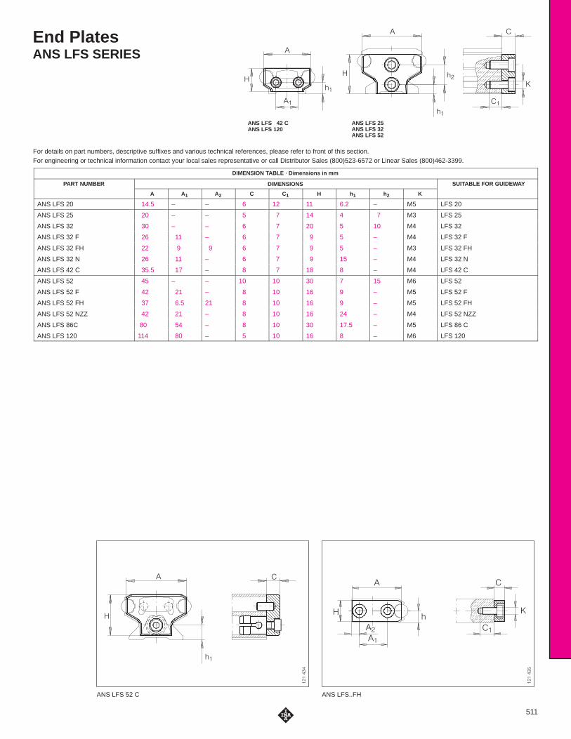
End PlatesANS LFS SERIES
For details on part numbers, descriptive suffixes and various technical references, please refer to front of this section.For engineering or technical information contact your local sales representative or call Distributor Sales (800)523-6572 or Linear Sales (800)462-3399.
�
�
��
��
�
� ��
��
�
�
ANS LFS 42 CANS LFS 120
ANS LFS 52 C
�������
ANS LFS..FH
�������
�
�
��
�
�
��
��
�
�
�
ANS LFS 25ANS LFS 32ANS LFS 52
511
DIMENSION TABLE · Dimensions in mm
PART NUMBER DIMENSIONS SUITABLE FOR GUIDEWAYPART NUMBER
A A1 A2 C C1 H h1 h2 K
SUITABLE FOR GUIDEWAY
ANS LFS 20 14.5 – – 6 12 11 6.2 – M5 LFS 20
ANS LFS 25 20 – – 5 7 14 4 7 M3 LFS 25
ANS LFS 32 30 – – 6 7 20 5 10 M4 LFS 32
ANS LFS 32 F 26 11 – 6 7 9 5 – M4 LFS 32 F
ANS LFS 32 FH 22 9 9 6 7 9 5 – M3 LFS 32 FH
ANS LFS 32 N 26 11 – 6 7 9 15 – M4 LFS 32 N
ANS LFS 42 C 35.5 17 – 8 7 18 8 – M4 LFS 42 C
ANS LFS 52 45 – – 10 10 30 7 15 M6 LFS 52
ANS LFS 52 F 42 21 – 8 10 16 9 – M5 LFS 52 F
ANS LFS 52 FH 37 6.5 21 8 10 16 9 – M5 LFS 52 FH
ANS LFS 52 NZZ 42 21 – 8 10 16 24 – M4 LFS 52 NZZ
ANS LFS 86C 80 54 – 8 10 30 17.5 – M5 LFS 86 C
ANS LFS 120 114 80 – 5 10 16 8 – M6 LFS 120

Lubrication And Wiper UnitsAB SERIES
Side PlatesABAL SERIES
For details on part numbers, descriptive suffixes and various technical references, please refer to front of this section.For engineering or technical information contact your local sales representative or call Distributor Sales (800)523-6572 or Linear Sales (800)462-3399.
��
��
�
��
�
�
∅ �
ABAL
�������
ABAL
�������
�
�
��
AB AB(view rotated through 90 °)
512
DIMENSION TABLE · Dimensions in mm
PART NUMBER MASS DIMENSIONS SUITABLE FOR TRACKROLLER
PART NUMBER
�
g
A A3 C1 C7 H1 H4 H5 K4for screws to
DIN 7 972
SUITABLE FOR TRACKROLLER
AB 32 30 80 6 11 5 32 7 7 St 2.9 LFL 32
AB 32 30 80 6 11 5 32 7 7 St 2.9 LFDL 32
AB 52 100 120 20 18 8.5 49.5 9.5 15 St 4.8 LFL 52
AB 52 100 120 20 18 8.5 49.5 9.5 15 St 4.8 LFDL 52
AB 52/1 130 135 20 18 8.5 55 12 20.6 St 4.8 LFL 52 E
DIMENSION TABLE · Dimensions in mm
PART NUMBER MASS DIMENSIONS SUITABLE FOR CARRIAGE
PART NUMBER
�
g
A A1 C C7 H1
SUITABLE FOR CARRIAGE
ABAL 32 30 86 3 112 100 32 LFL 32
ABAL 52 40 130 5 136 117 49.5 LFL 52
ABAL 52/1 50 145 5 186 167 55 LFL 52 E

End StopsPAH, PASTP SERIES
For details on part numbers, descriptive suffixes and various technical references, please refer to front of this section.For engineering or technical information contact your local sales representative or call Distributor Sales (800)523-6572 or Linear Sales (800)462-3399.
�
���
�
��
��
��
��
��
�
PASTP
�������
��
�
�
PAH PAH
513
DIMENSION TABLE · Dimensions in mm
PART NUMBER MASS DIMENSIONS SUITABLE FOR GUIDEWAYPART NUMBER
�
g
A A1 C C1 D H H1 H3 H4 H5 A/F
SUITABLE FOR GUIDEWAY
PAH 32 50 46 21 30 15 10 39 32 19 7 14 5 LFS 32 C, N
PAH 52 170 75 35 43 20 16 70.5 58 36.5 9.5 30 6 LFS 52 C, NZZ
DIMENSION TABLE · Dimensions in mm
PART NUMBER MASS DIMENSIONS SUITABLE FOR GUIDEWAYPART NUMBER
�
g
D H3 K5 H
SUITABLE FOR GUIDEWAY
PASTP 20 8 20 7 M5 22.2 LFS 20
PASTP 25 8 20 7 M5 25 LFS 25
PASTP 32 10 16 11 M6 31 LFS 32
PASTP 42 10 16 11 M6 31 LFS 42 C
PASTP 52 10 20 11 M8 45 LFS 52
PASTP 86 10 20 11 M8 45 LFS 86 C

Groove StripsNAD SERIES
End CoversKA LFS..C, KA LFS..M SERIES
For details on part numbers, descriptive suffixes and various technical references, please refer to front of this section.For engineering or technical information contact your local sales representative or call Distributor Sales (800)523-6572 or Linear Sales (800)462-3399.
��
�
���
���
��
���
��
����
KA LFS..C
�������
KA LFS..M
�������
�
�
���
� ��
NAD
514
DIMENSION TABLE · Dimensions in mm
PART NUMBER MASS SUITABLE FOR GUIDEWAY
�
g/m
NAD 5��5,7 12 LFS 25 M
NAD 8�11,5 27 LFS 32 M
NAD 8�11,5 27 LFS 52 M
DIMENSION TABLE · Dimensions in mm
PART NUMBER MASS DIMENSIONS SUITABLE FOR GUIDEWAYPART NUMBER
�
g
a8 a9 c1 h8 h9
SUITABLE FOR GUIDEWAY
KA LFS 25 M 10 24.4 55.4 3 45.4 30.9 LFS 25 M
KA LFS 32 C 10 31.4 23.4 3 19.4 – LFS 32 C
KA LFS 32 M 12 31.4 74.4 3 59.9 46.4 LFS 32 M
KA LFS 42 C 12 41.4 27.4 3 19.4 – LFS 42 C
KA LFS 52 C 13 51.6 39.4 3 33.4 – LFS 52 C
KA LFS 52 M 15 51.6 111.4 4 98 64.8 LFS 52 M
KA LFS 86 C 15 85.6 70.4 4 33.4 – LFS 86 C
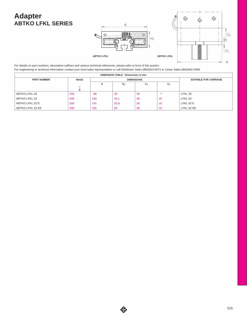
AdapterABTKO LFKL SERIES
For details on part numbers, descriptive suffixes and various technical references, please refer to front of this section.For engineering or technical information contact your local sales representative or call Distributor Sales (800)523-6572 or Linear Sales (800)462-3399.
��
��
�
�
��
ABTKO LFKL ABTKO LFKL
515
DIMENSION TABLE · Dimensions in mm
PART NUMBER MASS DIMENSIONS SUITABLE FOR CARRIAGEPART NUMBER
�
g
A H1 C7 C1
SUITABLE FOR CARRIAGE
ABTKO LFKL 32 200 86 32 39 7 LFKL 32
ABTKO LFKL 52 400 130 46.1 39 10 LFKL 52
ABTKO LFKL 52 E 500 145 53.8 39 10 LFKL 52 E
ABTKO LFKL 52 EE 500 155 55 39 10 LFKL 52 EE

INA SALES OFFICESMANUFACTURING PLANTS
SALES OFFICES
TORONTO, CANADA
INA Canada Inc.2871 Plymouth DriveOakville, Ontario L6H 5S5Toll Free: 800-263-4397
Telephone: 905-829-2750Fax: 905-829-2563
MONTREAL, CANADA
INA Canada Inc.149 Avenue GuthrieDorval, Quebec H9P 2P1Toll Free: 800-361-7015
Telephone: 514-631-2214Fax: 514-631-9571
VANCOUVER, CANADA
INA Canada Inc.106-1668 Derwent WayDelta, British Columbia, V3M R9Toll Free: 800-663-9006
Telephone: 604-526-3500Fax: 604-526-6544
MEXICO CITY, MEXICO
INA Mexico, S.A. de C.V.Paseo de la Reforma 383-704Col. Cuauhtemoc06500 Mexico D.F.Telephone: 525-525-00-12 / 01-84Fax: 525-525-01-94
OTHER COUNTRIES
Argentina ItalyAustralia JapanAustria KoreaBelgium NetherlandsBrazil NorwayDenmark PortugalFinland South AfricaFrance SpainGermany SwedenGreat Britain Turkey
MANUFACTURING PLANTS
PARENT COMPANY
INA Waelzlager Schaeffler oHGIndustriestrasse 1-3P.O. Box 1220D-91074 HerzogenaurachGermanyTelephone: (49132) 82-0Fax: (49132) 82 49 33
UNITED STATES
PLANT IINA USA CorporationOne INA DriveP.O. Box 390Cheraw, South Carolina 29520Telephone: 843-537-9341/9346Fax: 843-537-8751
PLANT IIINA USA CorporationHighway 9 WestP.O. Box 390Cheraw, South Carolina 29520Telephone: 843-537-9341Fax: 843-537-8752
PLANT IIIINA USA Corporation308 Springhill Farm RoadFort Mill, South Carolina 29715Telephone: 803-547-7990Fax: 803-548-8597
PLANT IVINA USA CorporationNew Cut Road, P.O. Box 570Spartanburg, South Carolina 29304Telephone: 864-583-4541Fax: 864-591-8890
PLANT VINA USA Corporation200 Evans RowCheraw, South Carolina 29520Telephone: 843-537-9341Fax: 843-537-8751
OTHER COUNTRIES
Australia Great BritainBrazil ItalyCanada KoreaChina SlovakiaFrance SpainGermany Switzerland

ATLANTA
1870 The Exchange, Suite 100Atlanta, Georgia 30339Telephone: 770-951-7015Fax: 770-951-7092
BUFFALO
336 Harris Hill Road, Suite 100Williamsville, New York 14221Telephone: 716-631-1533Fax: 716-631-8741
CHARLOTTE
377 Carowinds Boulevard, Suite 120Fort Mill, South Carolina 29708Telephone: 803-547-7970Fax: 803-548-6361
CHICAGO
2525 Cabot Drive, Suite 202Lisle, Illinois 60532Telephone: 630-955-9360Fax: 630-955-9365
CLEVELAND
12306 Woodward BoulevardGarfield Heights, Ohio 44125Telephone: 216-587-4393Fax: 216-587-2655
DALLAS
3939 Belt Line Road, Suite 365Addison, Texas 75001Telephone: 972-488-2544Fax: 972-488-2802
DAYTON
261 Regency Ridge DriveCenterville, Ohio 45459Telephone: 937-433-6404Fax: 937-433-6814
DETROIT
335 East Big Beaver Road, Suite 101Troy, Michigan 48083Telephone: 248-528-9080Fax: 248-619-2139
FLINT
771A E. Main Street, P.O. Box 666Flushing, Michigan 48433Telephone: 810-659-3607Fax: 810-659-4771
PHILADELPHIA
3399 Progress DriveBensalem, Pennsylvania 19020Telephone: 215-245-3485Fax: 215-245-7779
PHOENIX
11024 N. 28th Street, Suite 208Phoenix, Arizona 85029Telephone: 602-588–9304Fax: 602-588–9318
QUAD CITIES
300 Northwest Banktower2550 Middle Road Bettendorf, Iowa 52722Telephone: 319-355-0383Fax: 319-355-1937
RICHMOND
8003 Franklin Farms Drive, Suite 229BRichmond, Virginia 23229Telephone: 804-527-0901Fax: 804-527-0992
SAN FRANCISCO
3478 Buskirk Avenue, Suite 1043Pleasant Hill, California 94523Telephone: 925-746-7103Fax: 925-946-9936
SEATTLE
40 Lake Bellevue, Suite 100Bellevue, Washington 98005Telephone: 425-646-9477Fax: 425-646-9471
TAMPA
25327 Celmar StreetBrooksville, Florida 34601Telephone: 352-797-0620Fax: 352-797-0630
HARTFORD
1799 Farmington Ave., Bldg. B-2, P.O. Box 528Unionville, Connecticut 06085Telephone: 860-673-5236Fax: 860-673-5270
HOUSTON
10101 Southwest Freeway, Suite 400Houston, Texas 77074Telephone: 713-219-1430Fax: 713-219-1431
INDIANAPOLIS
7301 Elm Ridge RoadIndianapolis, Indiana 46236Telephone: 317-823-7268Fax: 317-823-7269
KANSAS CITY
4201 N.E. Lakewood Way, Suite 101Lee’s Summit, Missouri 64064Telephone: 816-795-9311Fax: 816-795-9322
LOS ANGELES
767 North Main StreetOrange, California 92868Telephone: 714-744-1022Fax: 714-744-2640
LOUISVILLE
14419 Micawber WayLouisville, Kentucky 40245Telephone: 502-254-9590Fax: 502-254-2760
MEMPHIS
1922 Exeter Road, Suite 20Germantown, Tennessee 38138Telephone: 901-756-0023Fax: 901-756-0260
MILWAUKEE
N16 W23233 Stoneridge Drive, Suite 220Waukesha, Wisconsin 53188Telephone: 414-544-8270Fax: 414-544-8271
MINNEAPOLIS
80 W. 78th Street, Suite 270CChanhassen, Minnesota 55317Telephone: 612-934-8822Fax: 612-934-8833
USA SALES OFFICES
Corporate OfficesINA USA CORPORATION308 Springhill Farm Road
Fort Mill, South Carolina 29715Telephone: 803-548-8500 Fax: 803-548-8599
INA LINEAR TECHNIKA Division Of INA USA Corporation
247 Rittenhouse CircleBristol, Pennsylvania 19007
Telephone: 215-781-6900 Fax: 215-781-9830