tr100 - terexconstructionsupport.terex.com/_library/technical_assistance/terex... · terex...
TRANSCRIPT

TEREX Equipment Limited
Ope
rato
r Han
dboo
k
TR100
15504845OHE783
Operator Handbook Operator Handbook
Original Operating Instructions

This Page Intentionally Left Blank
TEREX Equipment Limited TEREX Equipment Limited TEREX Equipment Limited TEREX Equipment Limited TEREX Equipment Limited Operator Handbook
Ope
rato
r Han
dboo
k
TR10
0
15504845OHE783
TEREX Equipment Limited Operator Handbook Re-order
Issued by;Customer Support Department
Terex Equipment LimitedNewhouse Industrial Estate
Motherwell, ML1 5RYScotland
Tel; +44 (0) 1698 732121Fax; +44 (0) 1698 503210
http//:constructionsupport.terex.comwww.terex.com
OHE783 (CEC2)Re-order Part Number
15504845
This controlled document is the original instructionand should remain with the vehicle at all times.
Revision: November 2011
Dealer:

This Page Intentionally Left Blank

TEREX Equipment Limited TEREX Equipment Limited TEREX Equipment Limited TEREX Equipment Limited TEREX Equipment Limited
Ope
rato
r Han
dboo
k
TR10
0
15504845OHE783
For further information on the subject matter detailed within this OperatorHandbook, please refer to Terex Equipment Limited Service Manuals andProduct Parts Books.
Alternatively, please contact;
Customer Support DepartmentTerex Equipment Limited
Newhouse Industrial EstateMotherwell, ML1 5RY
Tel; +44 (0) 1698 732121Fax; +44 (0) 1698 503210
http://constructionsupport.terex.com
www.terex.com
The illustrations, technical information, data and descriptive text in thismanual, to the best of our knowledge, were correct at the time of print. Theright to change specifications, equipment and maintenance instructions atany time without notice, is reserved as part of the Terex Equipment Limitedpolicy of continuous development and improvement of the product.
No part of this publication may be reproduced, transmitted in any form -electronic, mechanical, photocopying, recording, translating or by anyother means without prior permission of Customer Support Department -Terex Equipment Limited.
Please refer to TEREX Specification Sheets or consult FactoryRepresentatives to ensure that information is current.
TEREX Equipment Limited Operator Handbook - Introduction

This Page Intentionally Left Blank
ONLY TRAINED COMPETENT PERSONNELSHOULD BE ALLOWED TO OPERATE THIS
VEHICLE
The operator is responsible and must befamiliar with the contents of the Operator's
Handbook and any Local / Nationalregulations prior to operating this vehicle.

This Page Intentionally Left Blank
CALIFORNIAProposition 65 Warnings
WARNING: Diesel engine exhaust andsome of its constituents are known to theState of California to cause cancer, birthdefects, and other reproductive harm.
WARNING: Battery posts, terminalsand related accessories contain leadand lead compounds, chemicalsknown to the State of California to causecancer and reproductive harm.Wash hands after handling.
SPARE PARTS STATEMENT
When carrying out repairs, alterations or fitting attachments, it is important that only genuinespare parts are used to ensure the operating safety of the machine is not impaired.
It is only by using genuine parts that the technical requirements stipulated by the manufacturercan be maintained.
If a General Operating Approval is issued for this machine, it may be considered null and voidif non-genuine parts are used.

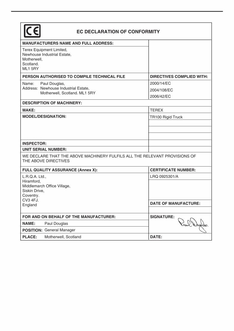
EC DECLARATION OF CONFORMITY
MANUFACTURERS NAME AND FULL ADDRESS:
Terex Equipment Limited,
Newhouse Industrial Estate,
Motherwell,
Scotland.
ML1 5RY
DESCRIPTION OF MACHINERY:
MAKE: TEREX
2000/14/EC
2004/108/EC
2006/42/EC
Name:
Address:
Paul Douglas,
Newhouse Industrial Estate,
Motherwell, Scotland. ML1 5RY
PERSON AUTHORISED TO COMPILE TECHNICAL FILE DIRECTIVES COMPLIED WITH:
MODEL/DESIGNATION:
UNIT SERIAL NUMBER:
INSPECTOR:
WE DECLARE THAT THE ABOVE MACHINERY FULFILS ALL THE RELEVANT PROVISIONS OF
THE ABOVE DIRECTIVES
FULL QUALITY ASSURANCE (Annex X):
L.R.Q.A. Ltd.,
Hiramford,
Middlemarch Office Village,
Siskin Drive,
Coventry.
CV3 4FJ.
England
NAME: Paul Douglas
General Manager
Motherwell, Scotland
POSITION:
PLACE:
CERTIFICATE NUMBER:
LRQ 0925301/A
FOR AND ON BEHALF OF THE MANUFACTURER:
DATE OF MANUFACTURE:
SIGNATURE:
DATE:
TR100 Rigid Truck
SPARE PARTS STATEMENT
When carrying out repairs, alterations or fitting attachments, it is important that only genuine
spare parts are used to ensure the operating safety of the machine is not impaired.
It is only by using genuine parts that the technical requirements stipulated by the manufacturer
can be maintained.
If a General Operating Approval is issued for this machine, it may be considered null and void
if non-genuine parts are used.
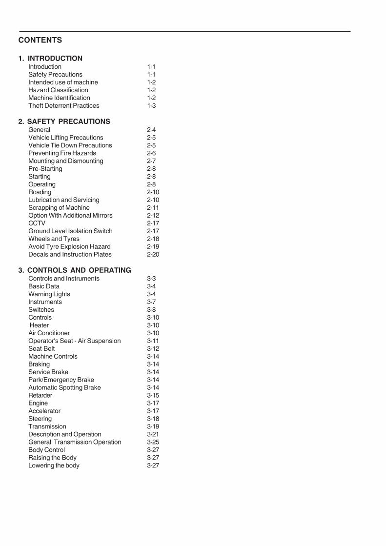
CONTENTS
1. INTRODUCTIONIntroduction 1-1Safety Precautions 1-1Intended use of machine 1-2Hazard Classification 1-2Machine Identification 1-2Theft Deterrent Practices 1-3
2. SAFETY PRECAUTIONSGeneral 2-4Vehicle Lifting Precautions 2-5Vehicle Tie Down Precautions 2-5Preventing Fire Hazards 2-6Mounting and Dismounting 2-7Pre-Starting 2-8Starting 2-8Operating 2-8Roading 2-10Lubrication and Servicing 2-10Scrapping of Machine 2-11Option With Additional Mirrors 2-12CCTV 2-17Ground Level Isolation Switch 2-17Wheels and Tyres 2-18Avoid Tyre Explosion Hazard 2-19Decals and Instruction Plates 2-20
3. CONTROLS AND OPERATINGControls and Instruments 3-3Basic Data 3-4Warning Lights 3-4Instruments 3-7Switches 3-8Controls 3-10 Heater 3-10Air Conditioner 3-10Operator's Seat - Air Suspension 3-11Seat Belt 3-12Machine Controls 3-14Braking 3-14Service Brake 3-14Park/Emergency Brake 3-14Automatic Spotting Brake 3-14Retarder 3-15Engine 3-17Accelerator 3-17Steering 3-18Transmission 3-19Description and Operation 3-21General Transmission Operation 3-25Body Control 3-27Raising the Body 3-27Lowering the body 3-27

This Page Intentionally Left Blank
CONTENTS
4. OPERATING THE TRUCKPre-Starting Inspection 4-3Component Checks 4-4Suspension Ride Struts 4-6Engine Operation 4-7Starting the Engine 4-8Starting the Engine at low ambientTemperature 4-10Starting the Engine with Jumper Cables 4-10Pre-Operating Checks 4-11Brake Function Checks 4-12Driving and Stopping 4-13Stopping the Engine 4-14Parking 4-16
5. WORKING THE TRUCKWorking the Truck 5-3Loading 5-3Hauling 5-5Dumping 5-6Empty Return 5-7
6. ROADINGRoading 6-3General 6-3Preparation Prior to Roading 6-3In Case Of Trouble 6-4
7. MOVING DISABLED TRUCKMoving Disabled Truck 7-3
8. LUBRICATION AND SERVICINGSafety Precautions 8-3Lubrication and Servicing 8-4Lubrication and Service Chart 8-5Miscellaneous Servicing 8-7Service Capacities 8-8Recommended Lubricants 8-9Air Conditioning Re-start Procedure 8-10Tyre Pressure 8-10
9. TECHNICAL DATATechnical Data - TR100 9-3
10.SYMBOL IDENTIFICATION 10-3

This Page Intentionally Left Blank
1-1
Introduction
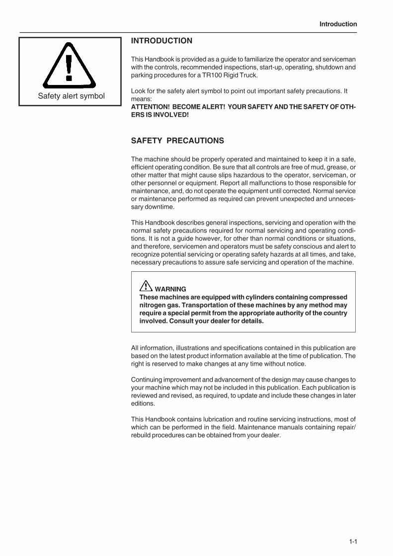
INTRODUCTION
This Handbook is provided as a guide to familiarize the operator and servicemanwith the controls, recommended inspections, start-up, operating, shutdown andparking procedures for a TR100 Rigid Truck.
Look for the safety alert symbol to point out important safety precautions. Itmeans:ATTENTION! BECOME ALERT! YOUR SAFETY AND THE SAFETY OF OTH-ERS IS INVOLVED!
SAFETY PRECAUTIONS
The machine should be properly operated and maintained to keep it in a safe,efficient operating condition. Be sure that all controls are free of mud, grease, orother matter that might cause slips hazardous to the operator, serviceman, orother personnel or equipment. Report all malfunctions to those responsible formaintenance, and, do not operate the equipment until corrected. Normal serviceor maintenance performed as required can prevent unexpected and unneces-sary downtime.
This Handbook describes general inspections, servicing and operation with thenormal safety precautions required for normal servicing and operating condi-tions. It is not a guide however, for other than normal conditions or situations,and therefore, servicemen and operators must be safety conscious and alert torecognize potential servicing or operating safety hazards at all times, and take,necessary precautions to assure safe servicing and operation of the machine.
WARNINGThese machines are equipped with cylinders containing compressednitrogen gas. Transportation of these machines by any method mayrequire a special permit from the appropriate authority of the countryinvolved. Consult your dealer for details.
All information, illustrations and specifications contained in this publication arebased on the latest product information available at the time of publication. Theright is reserved to make changes at any time without notice.
Continuing improvement and advancement of the design may cause changes toyour machine which may not be included in this publication. Each publication isreviewed and revised, as required, to update and include these changes in latereditions.
This Handbook contains lubrication and routine servicing instructions, most ofwhich can be performed in the field. Maintenance manuals containing repair/rebuild procedures can be obtained from your dealer.
Safety alert symbol
1-2
Introduction
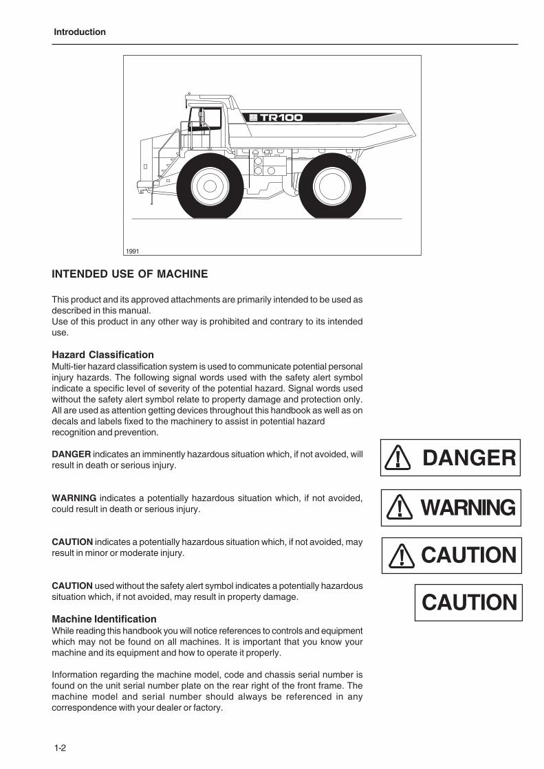
1991
INTENDED USE OF MACHINE
This product and its approved attachments are primarily intended to be used asdescribed in this manual.Use of this product in any other way is prohibited and contrary to its intendeduse.
Hazard ClassificationMulti-tier hazard classification system is used to communicate potential personalinjury hazards. The following signal words used with the safety alert symbolindicate a specific level of severity of the potential hazard. Signal words usedwithout the safety alert symbol relate to property damage and protection only.All are used as attention getting devices throughout this handbook as well as ondecals and labels fixed to the machinery to assist in potential hazardrecognition and prevention.
DANGER indicates an imminently hazardous situation which, if not avoided, willresult in death or serious injury.
WARNING indicates a potentially hazardous situation which, if not avoided,could result in death or serious injury.
CAUTION indicates a potentially hazardous situation which, if not avoided, mayresult in minor or moderate injury.
CAUTION used without the safety alert symbol indicates a potentially hazardoussituation which, if not avoided, may result in property damage.
Machine IdentificationWhile reading this handbook you will notice references to controls and equipmentwhich may not be found on all machines. It is important that you know yourmachine and its equipment and how to operate it properly.
Information regarding the machine model, code and chassis serial number isfound on the unit serial number plate on the rear right of the front frame. Themachine model and serial number should always be referenced in anycorrespondence with your dealer or factory.
DANGER
WARNING
CAUTION
CAUTION
1-3
Introduction
There is a dealer serving every part of the world where these products are sold.Your dealer is ready to provide you with any additional information needed andshould be consulted for additional publications for this machine.
THEFT DETERRENT PRACTICES
GeneralThe owner/operator should take the following precautions to discourage theft, toaid in the recovery in the event that the machine is stolen, or to reduce vandal-ism.
Actions to Discourage Theft and VandalismRemove all keys any time the machine is left unattended.
At night lock all doors and attach, secure or lock all anti-vandalism andanti-theft devices on the machine.
Immobilise the machine by removing a critical electrical or starting system de-vice.
Upon receipt of a machine, record the machine serial number and the serialnumbers of all major components and attachments. Keep this list up to date andfiled in a safe location for fast retrieval.
Place a decal or notice on the machine stating that all serial numbers are recorded.
Discourage the thief! Inspect the gates and fences of the machinery storageyard or construction site. Keep machines in well-lit areas and ask the local lawenforcement authorities to make frequent checks around the storage yard orwork site.
Establish liaison with neighbours and ask them to watch equipment left at jobsites and to report any suspicious activities to the local law enforcement au-thorities.
Make frequent inventories of machines to promptly detect losses or vandalism.
Actions to Aid in Recovery of Stolen Machines
In the event of theft, immediately notify the law enforcement authorities havingjurisdiction. Provide the investigating officer with name, type of equipment, chassisand serial numbers of major attachments and components. It is helpful to showthe investigating officer an Operator’s Handbook, photographs, and advertising,to familiarize him with the appearance of the machine.
Report the theft to the insurance company. Provide the model and all serialnumbers.
Report the model and serial numbers of the stolen machine to a dealer handlingthe respective line of equipment. Request that the dealer forward this sameinformation to the equipment manufacturer.

1-4
Introduction
This Page Intentionally Left Blank

2-1
2 - Safety

2-2
Safety
This Page Intentionally Left Blank
2-3
Safety
SAFETY
The machine should be properly operated and maintained to keep it in safe, efficient
operating condition. Be sure that all controls are free of mud, grease, or other matter
that might cause slips hazardous to the operator, serviceman, or other personnel or
equipment. Report all malfunctions to those responsible for maintenance, and, do
not operate the equipment until corrected. Normal service or maintenance performed
as required can prevent unexpected and unnecessary downtime.
This Handbook describes general inspections, servicing and operation with the
normal safety precautions required for normal servicing and operating conditions. It
is not a guide however, for other than normal conditions or situations, and therefore,
servicemen and operators must be safety conscious and alert to recognize potential
servicing or operating safety hazards at all times, and take necessary precautions to
assure safe servicing and operation of the machine.
These machines are equipped with cylinders containing compressednitrogen gas. Transportation of these machines by any method mayrequire a special permit from the appropriate authority of the countryinvolved. Consult your dealer for details.
All information, illustrations and specifications contained in this publication are
based on the latest product information available at the time of publication. The right
is reserved to make changes at any time without notice.
Continuing improvement and advancement of the design may cause changes to your
machine which may not be included in this publication. Each publication is reviewed
and revised, as required, to update and include these changes in later editions.
This Handbook contains lubrication and routine servicing instructions, most of which
can be performed in the field. Maintenance manuals containing repair/rebuild
procedures can be obtained from your dealer.
2-4
Safety
SAFETY PRECAUTIONS
General
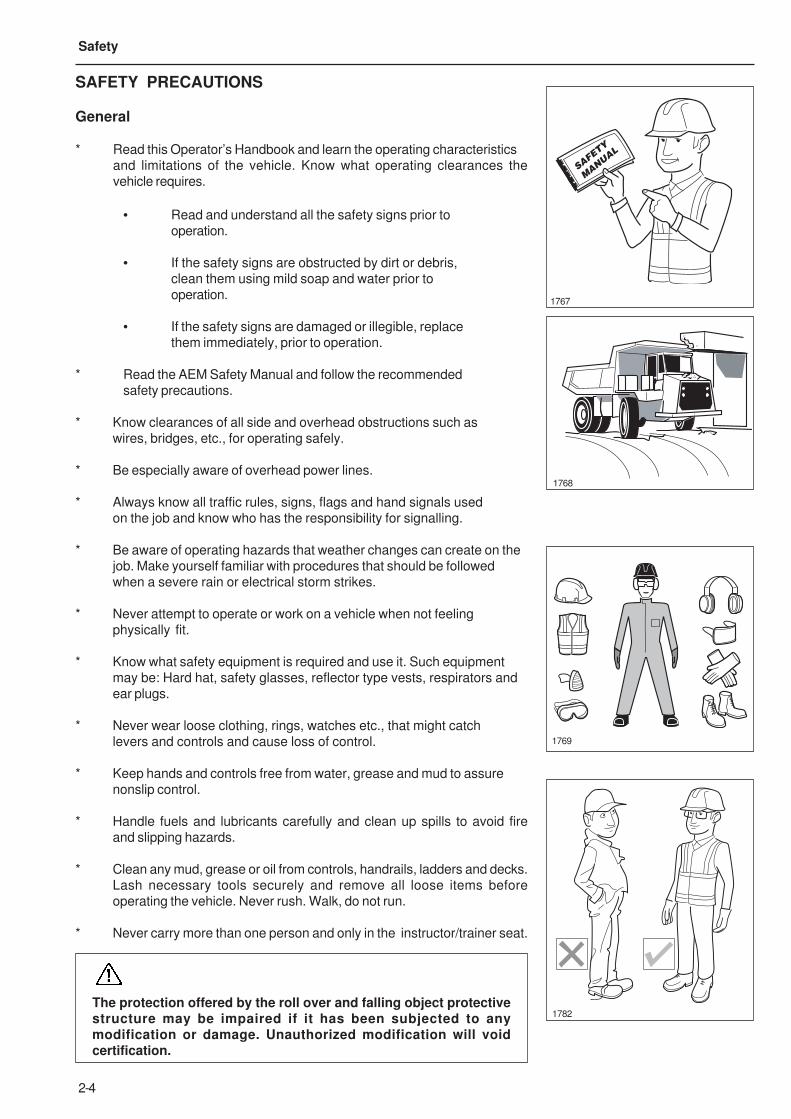
* Read this Operator’s Handbook and learn the operating characteristics
and limitations of the vehicle. Know what operating clearances the
vehicle requires.
• Read and understand all the safety signs prior to
operation.
• If the safety signs are obstructed by dirt or debris,
clean them using mild soap and water prior to
operation.
• If the safety signs are damaged or illegible, replace
them immediately, prior to operation.
* Read the AEM Safety Manual and follow the recommended
safety precautions.
* Know clearances of all side and overhead obstructions such as
wires, bridges, etc., for operating safely.
* Be especially aware of overhead power lines.
* Always know all traffic rules, signs, flags and hand signals used
on the job and know who has the responsibility for signalling.
* Be aware of operating hazards that weather changes can create on the
job. Make yourself familiar with procedures that should be followed
when a severe rain or electrical storm strikes.
* Never attempt to operate or work on a vehicle when not feeling
physically fit.
* Know what safety equipment is required and use it. Such equipment
may be: Hard hat, safety glasses, reflector type vests, respirators and
ear plugs.
* Never wear loose clothing, rings, watches etc., that might catch
levers and controls and cause loss of control.
* Keep hands and controls free from water, grease and mud to assure
nonslip control.
* Handle fuels and lubricants carefully and clean up spills to avoid fire
and slipping hazards.
* Clean any mud, grease or oil from controls, handrails, ladders and decks.
Lash necessary tools securely and remove all loose items before
operating the vehicle. Never rush. Walk, do not run.
* Never carry more than one person and only in the instructor/trainer seat.
The protection offered by the roll over and falling object protectivestructure may be impaired if it has been subjected to anymodification or damage. Unauthorized modification will voidcertification.
1782
1769
1768
SAFETY
MANUAL
1767
2-5
Safety
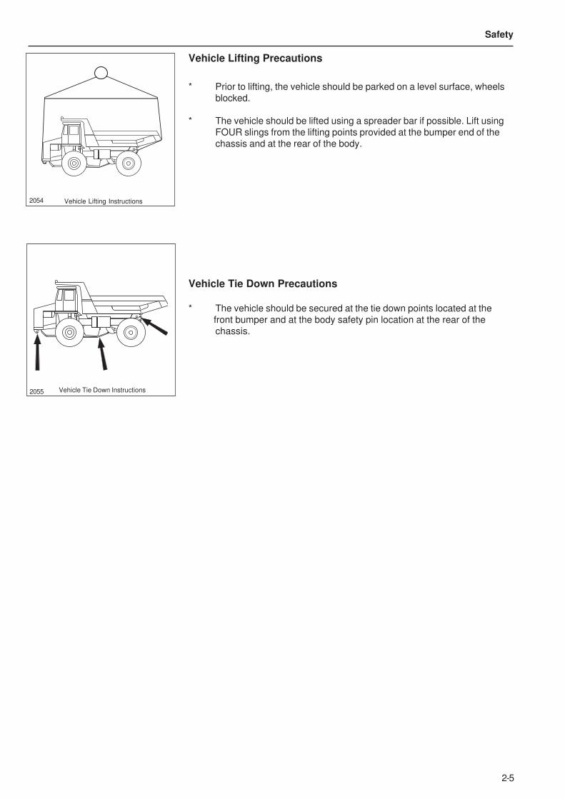
Vehicle Lifting Precautions
* Prior to lifting, the vehicle should be parked on a level surface, wheels
blocked.
* The vehicle should be lifted using a spreader bar if possible. Lift using
FOUR slings from the lifting points provided at the bumper end of the
chassis and at the rear of the body.
Vehicle Tie Down Precautions
* The vehicle should be secured at the tie down points located at the
front bumper and at the body safety pin location at the rear of the
chassis.
2054 Vehicle Lifting Instructions
2055 Vehicle Tie Down Instructions
2-6
Safety
PREVENTING FIRE HAZARDS
General Fire Precautions
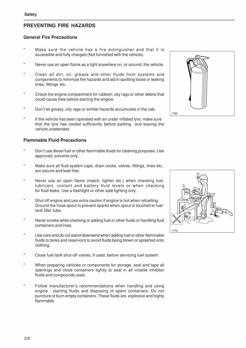
* Make sure the vehicle has a fire extinguisher and that it is
accessible and fully charged (Not furnished with the vehicle).
* Never use an open flame as a light anywhere on, or around, the vehicle.
* Clean all dirt, oil, grease and other fluids from systems and
components to minimize fire hazards and aid in spotting loose or leaking
lines, fittings etc..
* Check the engine compartment for rubbish, oily rags or other debris that
could cause fires before starting the engine.
* Don’t let greasy, oily rags or similar hazards accumulate in the cab.
* If the vehicle has been operated with an under inflated tyre, make sure
that the tyre has cooled sufficiently before parking and leaving the
vehicle unattended.
Flammable Fluid Precautions
* Don’t use diesel fuel or other flammable fluids for cleaning purposes. Use
approved, solvents only.
* Make sure all fluid system caps, drain cocks, valves, fittings, lines etc.,
are secure and leak free.
* Never use an open flame (match, lighter etc.) when checking fuel,
lubricant, coolant and battery fluid levels or when checking
for fluid leaks. Use a flashlight or other safe lighting only.
* Shut off engine and use extra caution if engine is hot when refuelling.
Ground the hose spout to prevent sparks when spout is touched to fuel
tank filler tube.
* Never smoke while checking or adding fuel or other fluids or handling fluid
containers and lines.
* Use care and do not stand downwind when adding fuel or other flammable
fluids to tanks and reservoirs to avoid fluids being blown or splashed onto
clothing.
* Close fuel tank shut-off valves, if used, before servicing fuel system.
* When preparing vehicles or components for storage, seal and tape all
openings and close containers tightly to seal in all volatile inhibitor
fluids and compounds used.
* Follow manufacturer’s recommendations when handling and using
engine - starting fluids and disposing of spent containers. Do not
puncture or burn empty containers. These fluids are explosive and highly
flammable.
FUEL
1770
1789
2-7
Safety
Electrical Hazard Precautions
* Never smoke or allow open flames or sparks near batteries.
* Leave battery box open when charging batteries in the vehicle for
adequate ventilation of explosive gas (hydrogen) produced.
* Always disconnect batteries before repairing electrical system to avoid
danger of fire-causing sparks. Disconnect battery ground cable first and
reconnect last.
* Always disconnect batteries & alternator leads before carrying out any
welding on the vehicle.
* Never check battery charge by placing metal objects across battery posts
to avoid sparks at battery posts.
* Use jumper cables only as recommended. Improper use can result in
battery explosion or unexpected vehicle motion.
* Never operate engine starter for more than 30 seconds and allow two
minutes between long cranking periods for cooling. An overheated starter
could cause a fire.
* If electric coolant or lubricant heaters are used, be sure to follow heater
manufacturer’s recommendations for use to avoid electrical and/or fire
hazards.
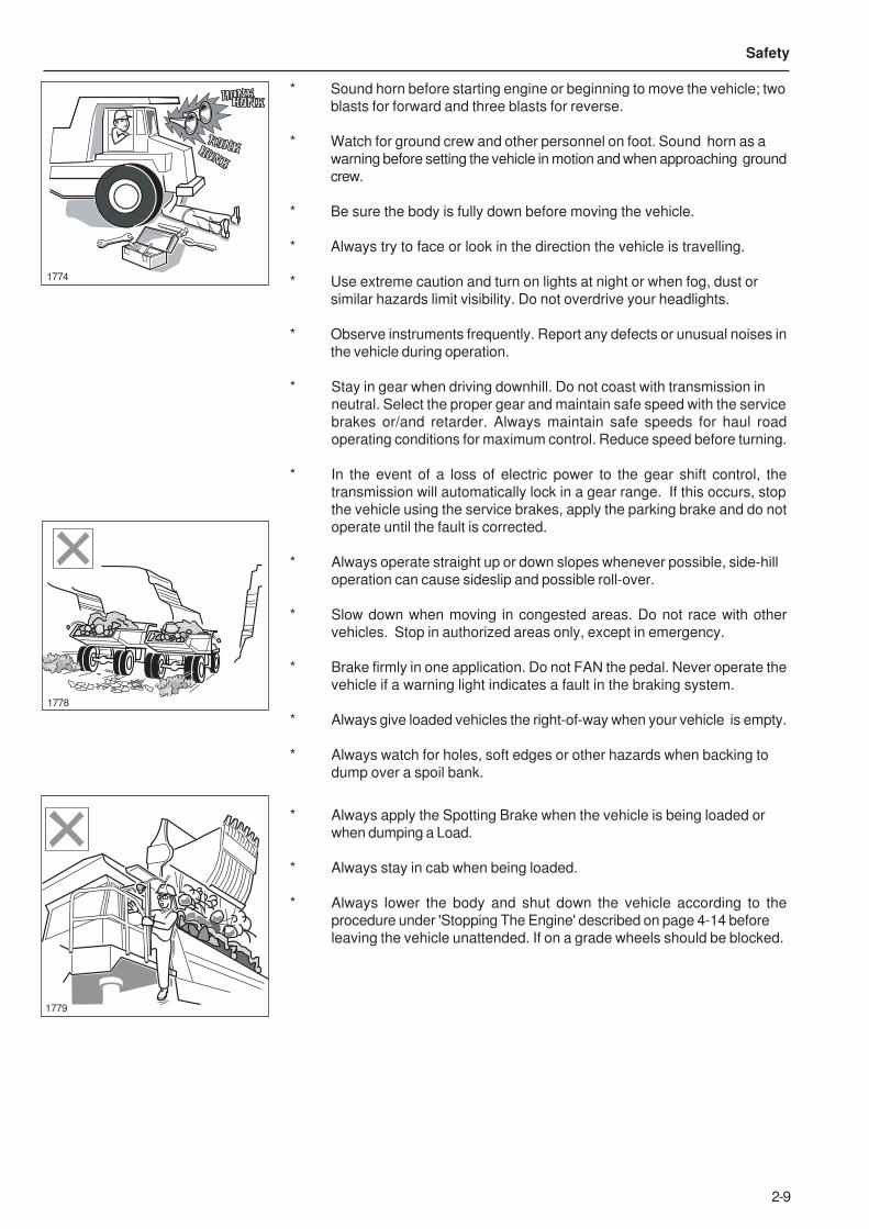
Mounting and Dismounting
* Only use steps and hand holds provided to mount or dismount
the vehicle. Do not grasp the steering wheel.
* Always face the access system and maintain at least three
points of support to mount or dismount the vehicle (two hands and
one foot, or two feet and one hand.
* Ensure walkways, stairways, platforms, handrails and handholds
are free of frost, ice, oil, water or anything else that could cause slip,
trip or falls.
* Never mount or dismount a moving vehicle. Never jump off the
vehicle.
1771
1772

2-8
Safety
Pre-Starting
* If engine is to be started and run indoors, ensure proper ventilation to
remove deadly exhaust gases.
* Always perform 'Pre-Starting Inspection' instructions described on
page 4-3 to ensure the vehicle is ready for operation.
* Always walk around the vehicle to make sure no-one is working on,
underneath or close to the vehicle before starting the engine or
operating the vehicle.
* Adjust, secure and latch the seat and fasten the seat belt before
starting the vehicle.
* Sound horn before starting the engine or beginning to move the
vehicle; two blasts for forward and three blasts for reverse.
Starting
* Do not start the engine or operate any control if there is a 'DO NOT
OPERATE' or similar warning sign attached to any control.
* Use jumper cables only as recommended. Improper use can result in
battery explosion or unexpected vehicle motion.
* Always obey 'Starting the Engine' instructions described on page 4-8.
* Do not bypass the vehicle’s neutral-start system. The neutral start sytem
must be repaired if it malfunctions.
* Start and operate the vehicle only from the operator’s seat.
Operating
* Ensure all cab glass, mirrors and light lenses are clean during vehicle
operation for maximum visibility. Ensure mirrors are properly
set / positioned.
* Always keep cab floor clear of anything that could restrict full operation of
pedals.
* Always make sure all gauges, warning/indicator lights and controls are
working properly before operating the vehicle.
* Always perform 'Pre-Operating Checks' described on page 4-11 to
ensure the vehicle is ready for operating.
* Always wear seat belts when operating the vehicle.
* In the event of a loss of steering pump output pressure, a fully
pressurized accumulator provides a maximum of two lock to lock turns of
the front wheels. A red warning light on the instrument panel illuminates
when steering pressure falls below 83 bar (1 200 lbf/in²). If this light
illuminates, indicating a loss of steering power, the machine must be
stopped immediately and no further operation attempted until the fault
is corrected.
* Do not operate if exposed personnel enter the immediate work area.
1773
1861
DO NOT
OPERATE
1775
1862
2-9
Safety
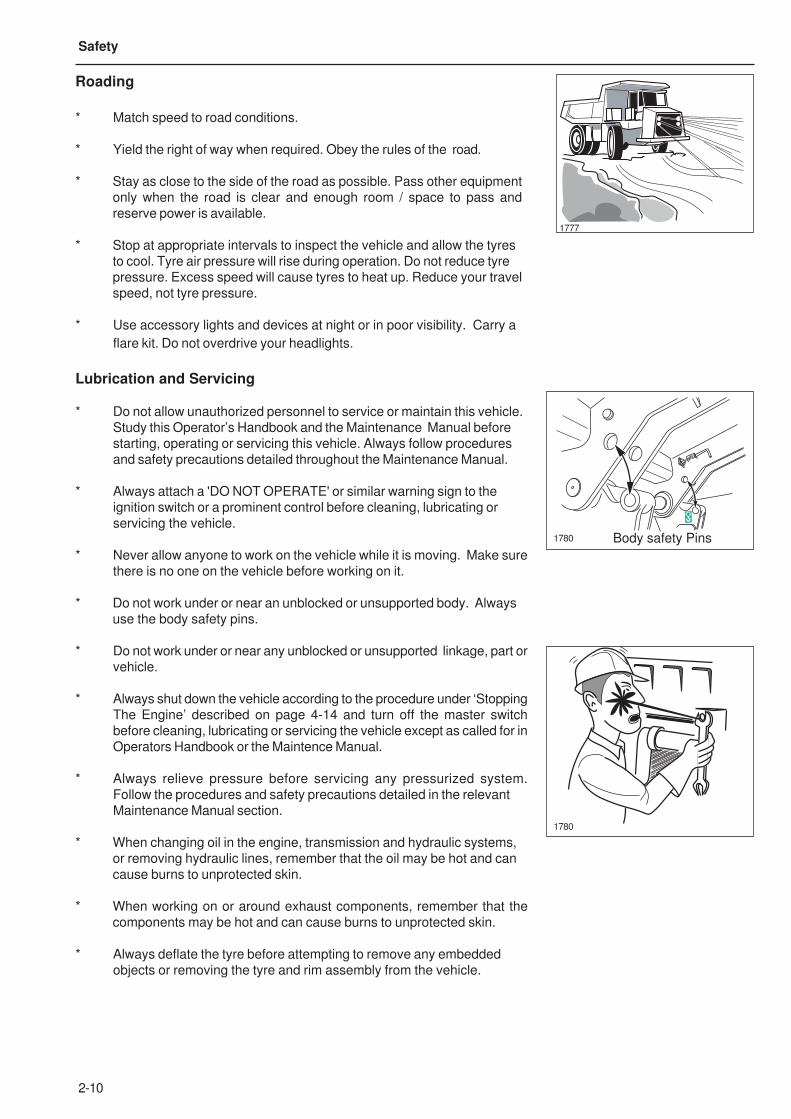
* Sound horn before starting engine or beginning to move the vehicle; two
blasts for forward and three blasts for reverse.
* Watch for ground crew and other personnel on foot. Sound horn as a
warning before setting the vehicle in motion and when approaching ground
crew.
* Be sure the body is fully down before moving the vehicle.
* Always try to face or look in the direction the vehicle is travelling.
* Use extreme caution and turn on lights at night or when fog, dust or
similar hazards limit visibility. Do not overdrive your headlights.
* Observe instruments frequently. Report any defects or unusual noises in
the vehicle during operation.
* Stay in gear when driving downhill. Do not coast with transmission in
neutral. Select the proper gear and maintain safe speed with the service
brakes or/and retarder. Always maintain safe speeds for haul road
operating conditions for maximum control. Reduce speed before turning.
* In the event of a loss of electric power to the gear shift control, the
transmission will automatically lock in a gear range. If this occurs, stop
the vehicle using the service brakes, apply the parking brake and do not
operate until the fault is corrected.
* Always operate straight up or down slopes whenever possible, side-hill
operation can cause sideslip and possible roll-over.
* Slow down when moving in congested areas. Do not race with other
vehicles. Stop in authorized areas only, except in emergency.
* Brake firmly in one application. Do not FAN the pedal. Never operate the
vehicle if a warning light indicates a fault in the braking system.
* Always give loaded vehicles the right-of-way when your vehicle is empty.
* Always watch for holes, soft edges or other hazards when backing to
dump over a spoil bank.
* Always apply the Spotting Brake when the vehicle is being loaded or
when dumping a Load.
* Always stay in cab when being loaded.
* Always lower the body and shut down the vehicle according to the
procedure under 'Stopping The Engine' described on page 4-14 before
leaving the vehicle unattended. If on a grade wheels should be blocked.
1778
1774
1779
2-10
Safety
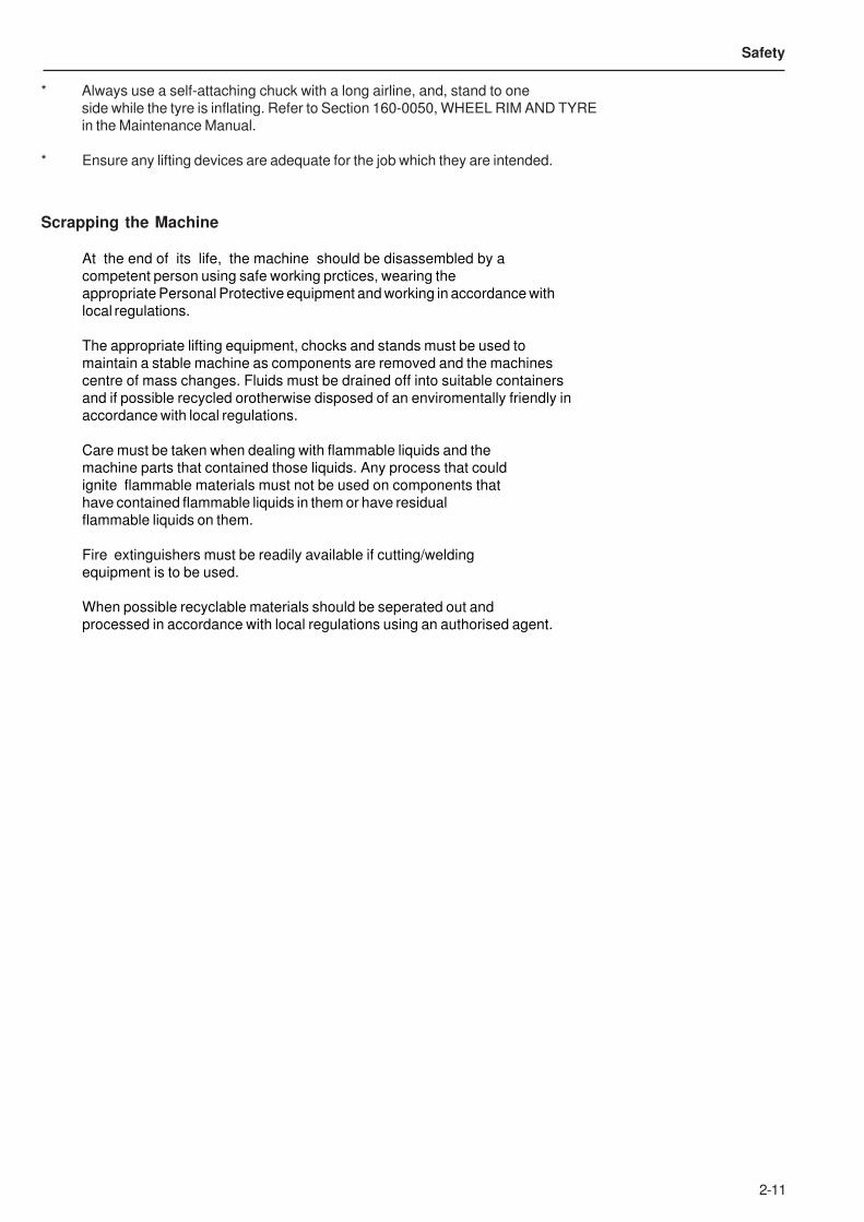
Roading
* Match speed to road conditions.
* Yield the right of way when required. Obey the rules of the road.
* Stay as close to the side of the road as possible. Pass other equipment
only when the road is clear and enough room / space to pass and
reserve power is available.
* Stop at appropriate intervals to inspect the vehicle and allow the tyres
to cool. Tyre air pressure will rise during operation. Do not reduce tyre
pressure. Excess speed will cause tyres to heat up. Reduce your travel
speed, not tyre pressure.
* Use accessory lights and devices at night or in poor visibility. Carry a
flare kit. Do not overdrive your headlights.
1777
Lubrication and Servicing
* Do not allow unauthorized personnel to service or maintain this vehicle.
Study this Operator’s Handbook and the Maintenance Manual before
starting, operating or servicing this vehicle. Always follow procedures
and safety precautions detailed throughout the Maintenance Manual.
* Always attach a 'DO NOT OPERATE' or similar warning sign to the
ignition switch or a prominent control before cleaning, lubricating or
servicing the vehicle.
* Never allow anyone to work on the vehicle while it is moving. Make sure
there is no one on the vehicle before working on it.
* Do not work under or near an unblocked or unsupported body. Always
use the body safety pins.
* Do not work under or near any unblocked or unsupported linkage, part or
vehicle.
* Always shut down the vehicle according to the procedure under ‘Stopping
The Engine’ described on page 4-14 and turn off the master switch
before cleaning, lubricating or servicing the vehicle except as called for in
Operators Handbook or the Maintence Manual.
* Always relieve pressure before servicing any pressurized system.
Follow the procedures and safety precautions detailed in the relevant
Maintenance Manual section.
* When changing oil in the engine, transmission and hydraulic systems,
or removing hydraulic lines, remember that the oil may be hot and can
cause burns to unprotected skin.
* When working on or around exhaust components, remember that the
components may be hot and can cause burns to unprotected skin.
* Always deflate the tyre before attempting to remove any embedded
objects or removing the tyre and rim assembly from the vehicle.
Body safety Pins1780
9271069
1780
2-11
Safety
* Always use a self-attaching chuck with a long airline, and, stand to one
side while the tyre is inflating. Refer to Section 160-0050, WHEEL RIM AND TYRE
in the Maintenance Manual.
* Ensure any lifting devices are adequate for the job which they are intended.
Scrapping the Machine
At the end of its life, the machine should be disassembled by a
competent person using safe working prctices, wearing the
appropriate Personal Protective equipment and working in accordance with
local regulations.
The appropriate lifting equipment, chocks and stands must be used to
maintain a stable machine as components are removed and the machines
centre of mass changes. Fluids must be drained off into suitable containers
and if possible recycled orotherwise disposed of an enviromentally friendly in
accordance with local regulations.
Care must be taken when dealing with flammable liquids and the
machine parts that contained those liquids. Any process that could
ignite flammable materials must not be used on components that
have contained flammable liquids in them or have residual
flammable liquids on them.
Fire extinguishers must be readily available if cutting/welding
equipment is to be used.
When possible recyclable materials should be seperated out and
processed in accordance with local regulations using an authorised agent.
2-12
Safety
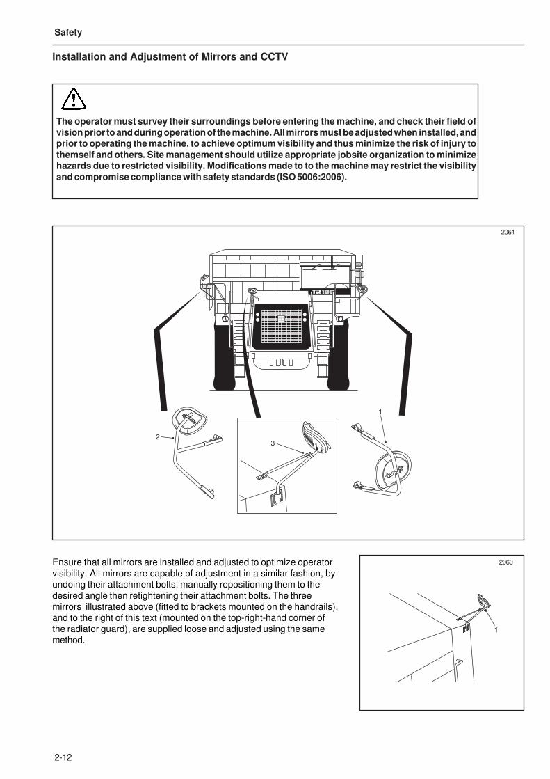
Installation and Adjustment of Mirrors and CCTV
The operator must survey their surroundings before entering the machine, and check their field ofvision prior to and during operation of the machine. All mirrors must be adjusted when installed, andprior to operating the machine, to achieve optimum visibility and thus minimize the risk of injury tothemself and others. Site management should utilize appropriate jobsite organization to minimizehazards due to restricted visibility. Modifications made to to the machine may restrict the visibilityand compromise compliance with safety standards (ISO 5006:2006).
2061
1
2060Ensure that all mirrors are installed and adjusted to optimize operator
visibility. All mirrors are capable of adjustment in a similar fashion, by
undoing their attachment bolts, manually repositioning them to the
desired angle then retightening their attachment bolts. The three
mirrors illustrated above (fitted to brackets mounted on the handrails),
and to the right of this text (mounted on the top-right-hand corner of
the radiator guard), are supplied loose and adjusted using the same
method.
1
32
2-13
Safety
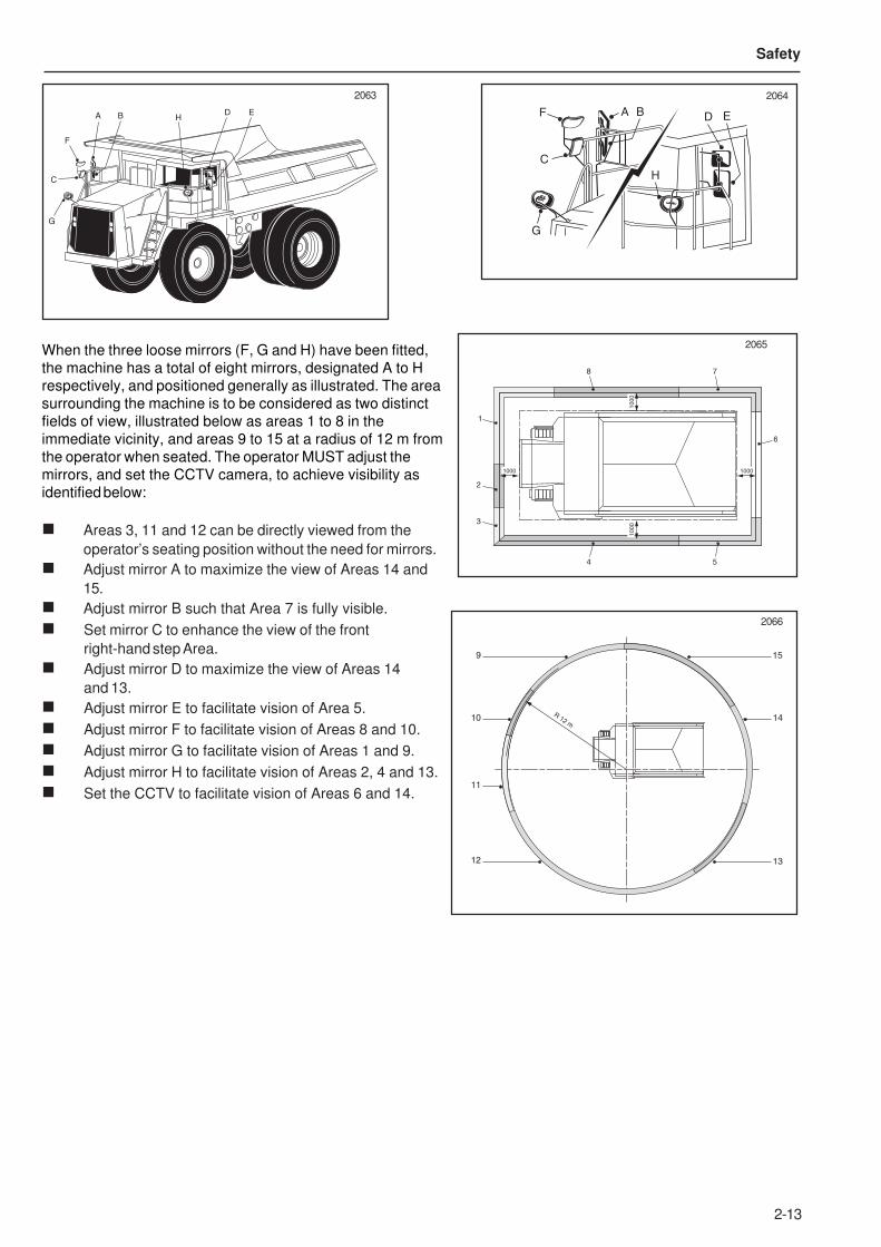
When the three loose mirrors (F, G and H) have been fitted,
the machine has a total of eight mirrors, designated A to H
respectively, and positioned generally as illustrated. The area
surrounding the machine is to be considered as two distinct
fields of view, illustrated below as areas 1 to 8 in the
immediate vicinity, and areas 9 to 15 at a radius of 12 m from
the operator when seated. The operator MUST adjust the
mirrors, and set the CCTV camera, to achieve visibility as
identified below:
n Areas 3, 11 and 12 can be directly viewed from the
operator’s seating position without the need for mirrors.
n Adjust mirror A to maximize the view of Areas 14 and
15.
n Adjust mirror B such that Area 7 is fully visible.
n Set mirror C to enhance the view of the front
right-hand step Area.
n Adjust mirror D to maximize the view of Areas 14
and 13.
n Adjust mirror E to facilitate vision of Area 5.
n Adjust mirror F to facilitate vision of Areas 8 and 10.
n Adjust mirror G to facilitate vision of Areas 1 and 9.
n Adjust mirror H to facilitate vision of Areas 2, 4 and 13.
n Set the CCTV to facilitate vision of Areas 6 and 14.
2063 2064
2065
2066
1000 1000
1000
1000
1
6
2
3
4 5
8 7
R 12 m
9 15
10 14
13
11
12
A B
C
D E
F
G
HA B
C
D EF
G
H
2-14
Safety
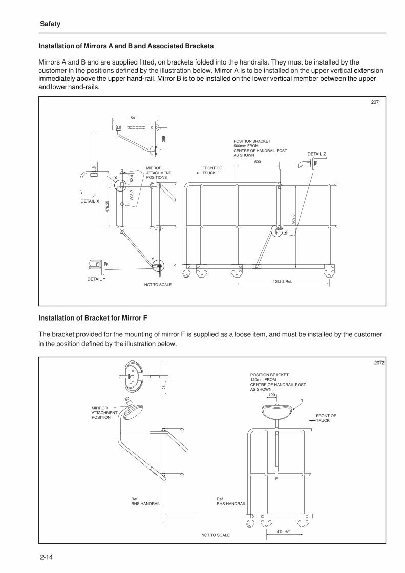
Installation of Mirrors A and B and Associated Brackets
Mirrors A and B and are supplied fitted, on brackets folded into the handrails. They must be installed by the
customer in the positions defined by the illustration below. Mirror A is to be installed on the upper vertical extension
immediately above the upper hand-rail. Mirror B is to be installed on the lower vertical member between the upper
and lower hand-rails.
Installation of Bracket for Mirror F
The bracket provided for the mounting of mirror F is supplied as a loose item, and must be installed by the customer
in the position defined by the illustration below.
2072
2071
541
500
MIRROR
ATTACHMENT
POSITIONS
FRONT OF
TRUCK
POSITION BRACKET
500mm FROM
CENTRE OF HANDRAIL POST
AS SHOWN
NOT TO SCALE
26
9
15
2.4
20
3.2
47
6.2
5
96
9.3
1092.2 Ref.
DETAIL X
DETAIL Y
DETAIL Z
X
Z
Y
120
50
FRONT OF
TRUCK
POSITION BRACKET
120mm FROM
CENTRE OF HANDRAIL POST
AS SHOWN
MIRROR
ATTACHMENT
POSITION
NOT TO SCALE412 Ref.
Ref.
RHS HANDRAIL
Ref.
RHS HANDRAIL
1
2-15
Safety
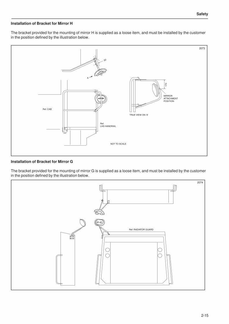
Installation of Bracket for Mirror H
The bracket provided for the mounting of mirror H is supplied as a loose item, and must be installed by the customer
in the position defined by the illustration below.
Installation of Bracket for Mirror G
The bracket provided for the mounting of mirror G is supplied as a loose item, and must be installed by the customer
in the position defined by the illustration below.
2073
17
0
50
MIRROR
ATTACHMENT
POSITION
TRUE VIEW ON 'A'
A
Ref.
LHS HANDRAIL
Ref. CAB
NOT TO SCALE
2074
Ref. RADIATOR GUARD
2-16
Safety
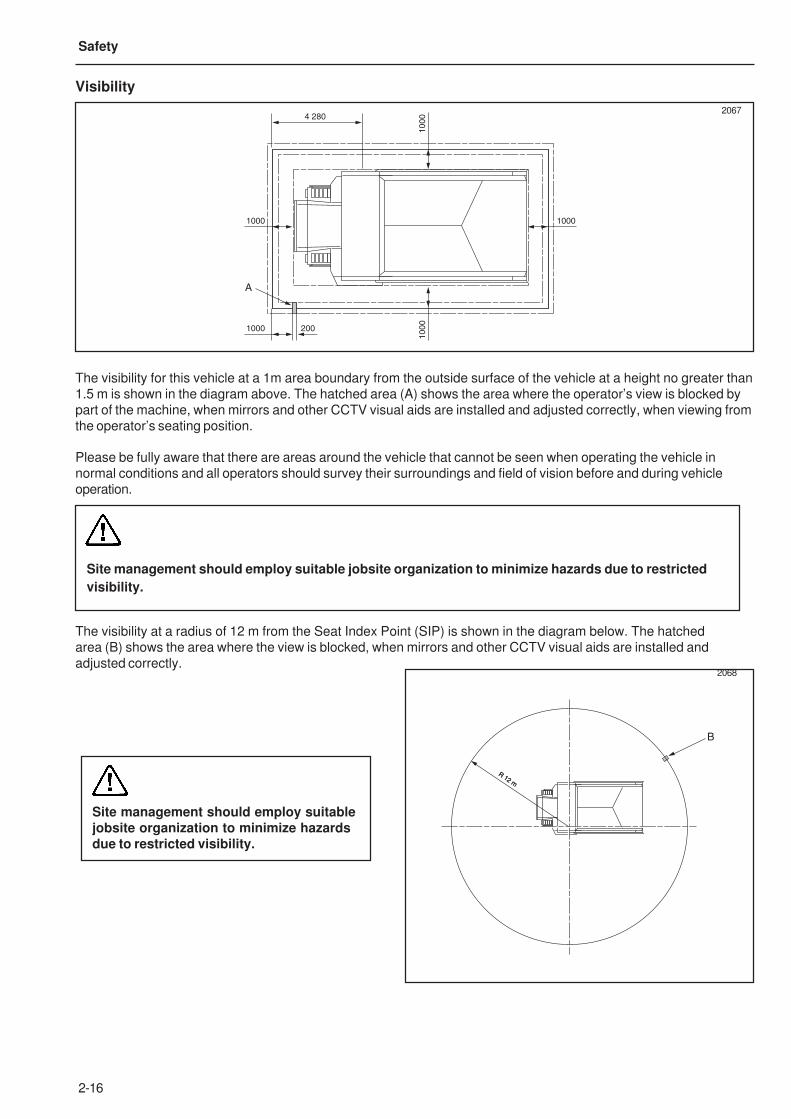
Please be fully aware that there are areas around the vehicle that cannot be seen when operating the vehicle in
normal conditions and all operators should survey their surroundings and field of vision before and during vehicle
operation.
Site management should employ suitable jobsite organization to minimize hazards due to restricted
visibility.
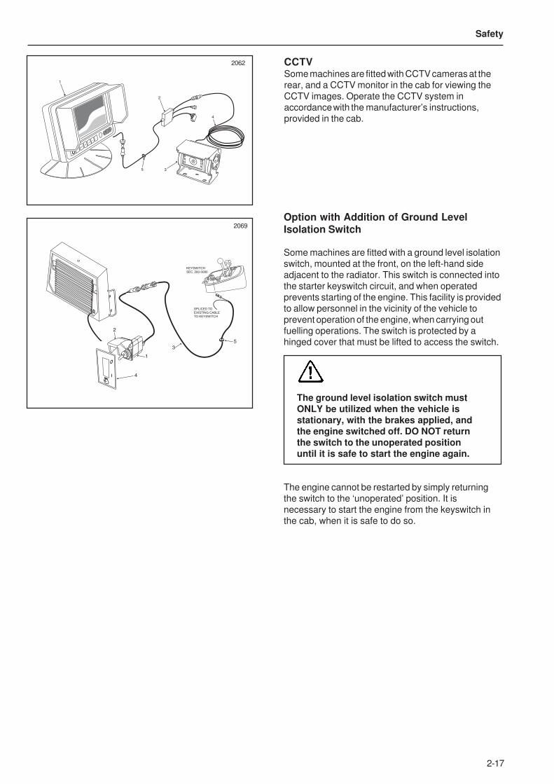
The visibility at a radius of 12 m from the Seat Index Point (SIP) is shown in the diagram below. The hatched
area (B) shows the area where the view is blocked, when mirrors and other CCTV visual aids are installed and
adjusted correctly.
Site management should employ suitablejobsite organization to minimize hazardsdue to restricted visibility.
2068
R 12 m
B
R 12 m
The visibility for this vehicle at a 1m area boundary from the outside surface of the vehicle at a height no greater than
1.5 m is shown in the diagram above. The hatched area (A) shows the area where the operator’s view is blocked by
part of the machine, when mirrors and other CCTV visual aids are installed and adjusted correctly, when viewing from
the operator’s seating position.
Visibility
2067
1000
1000
1000 1000
1000
4 280
200
A
2-17
Safety
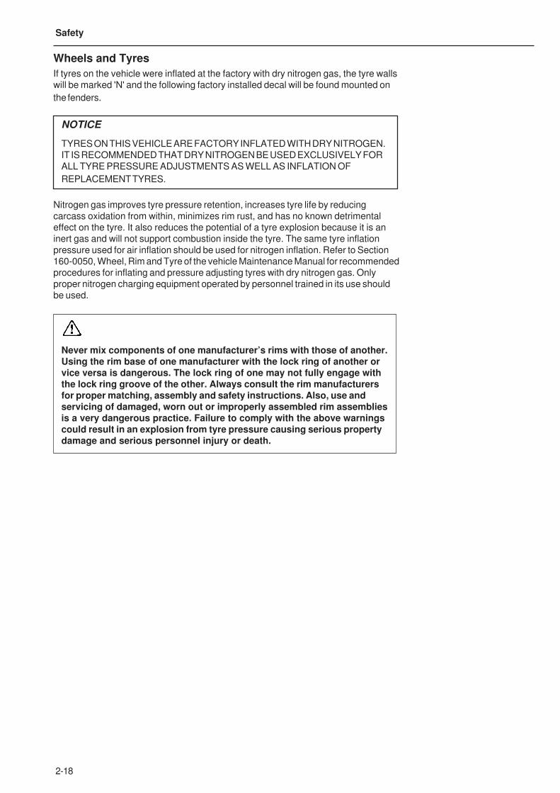
Option with Addition of Ground Level
Isolation Switch
Some machines are fitted with a ground level isolation
switch, mounted at the front, on the left-hand side
adjacent to the radiator. This switch is connected into
the starter keyswitch circuit, and when operated
prevents starting of the engine. This facility is provided
to allow personnel in the vicinity of the vehicle to
prevent operation of the engine, when carrying out
fuelling operations. The switch is protected by a
hinged cover that must be lifted to access the switch.
The ground level isolation switch mustONLY be utilized when the vehicle isstationary, with the brakes applied, andthe engine switched off. DO NOT returnthe switch to the unoperated positionuntil it is safe to start the engine again.
The engine cannot be restarted by simply returning
the switch to the ‘unoperated’ position. It is
necessary to start the engine from the keyswitch in
the cab, when it is safe to do so.
MENUSELECT
DN
UP
+
-
4
2
35
1
2062
2069
O
I
1
2
3
4
5
KEYSWITCH
SEC. 260-0080
SPLICED TO
EXISTING CABLE
TO KEYSWITCH
CCTVSome machines are fitted with CCTV cameras at the
rear, and a CCTV monitor in the cab for viewing the
CCTV images. Operate the CCTV system in
accordance with the manufacturer’s instructions,
provided in the cab.
2-18
Safety
Wheels and Tyres
If tyres on the vehicle were inflated at the factory with dry nitrogen gas, the tyre walls
will be marked 'N' and the following factory installed decal will be found mounted on
the fenders.
NOTICE
TYRES ON THIS VEHICLE ARE FACTORY INFLATED WITH DRY NITROGEN.
IT IS RECOMMENDED THAT DRY NITROGEN BE USED EXCLUSIVELY FOR
ALL TYRE PRESSURE ADJUSTMENTS AS WELL AS INFLATION OF
REPLACEMENT TYRES.
Nitrogen gas improves tyre pressure retention, increases tyre life by reducing
carcass oxidation from within, minimizes rim rust, and has no known detrimental
effect on the tyre. It also reduces the potential of a tyre explosion because it is an
inert gas and will not support combustion inside the tyre. The same tyre inflation
pressure used for air inflation should be used for nitrogen inflation. Refer to Section
160-0050, Wheel, Rim and Tyre of the vehicle Maintenance Manual for recommended
procedures for inflating and pressure adjusting tyres with dry nitrogen gas. Only
proper nitrogen charging equipment operated by personnel trained in its use should
be used.
Never mix components of one manufacturer’s rims with those of another.Using the rim base of one manufacturer with the lock ring of another orvice versa is dangerous. The lock ring of one may not fully engage withthe lock ring groove of the other. Always consult the rim manufacturersfor proper matching, assembly and safety instructions. Also, use andservicing of damaged, worn out or improperly assembled rim assembliesis a very dangerous practice. Failure to comply with the above warningscould result in an explosion from tyre pressure causing serious propertydamage and serious personnel injury or death.
2-19
Safety
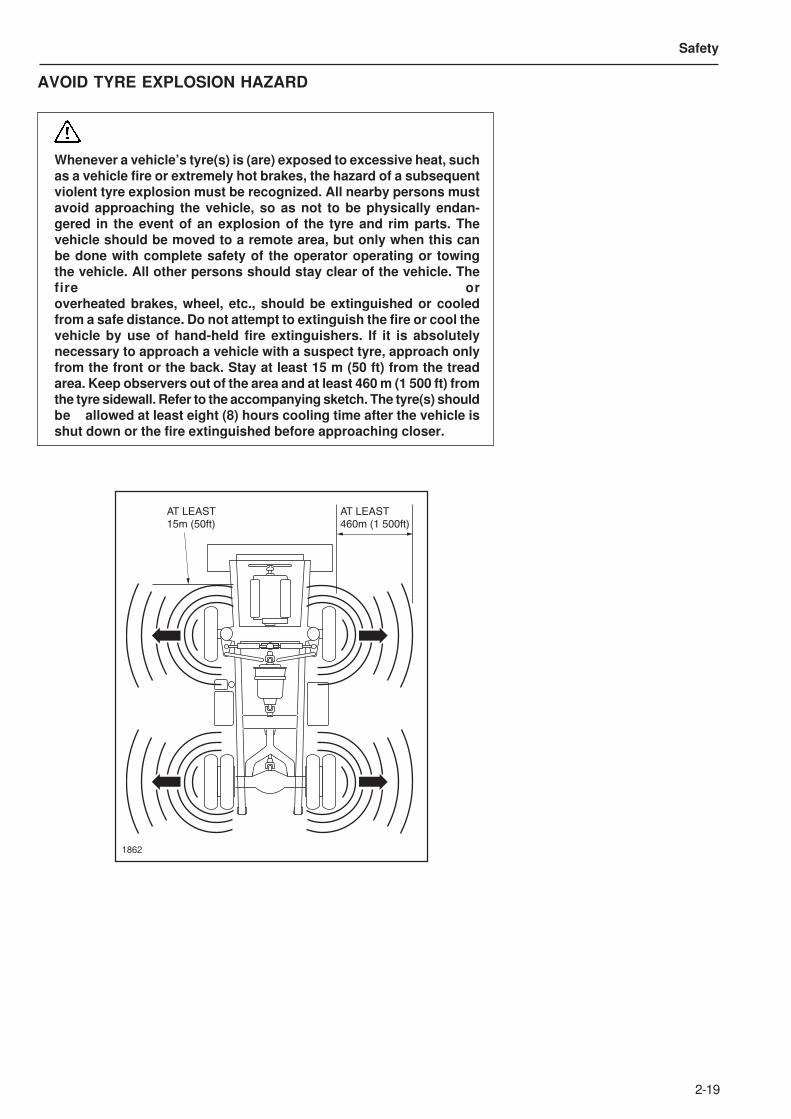
AVOID TYRE EXPLOSION HAZARD
Whenever a vehicle’s tyre(s) is (are) exposed to excessive heat, suchas a vehicle fire or extremely hot brakes, the hazard of a subsequentviolent tyre explosion must be recognized. All nearby persons mustavoid approaching the vehicle, so as not to be physically endan-gered in the event of an explosion of the tyre and rim parts. Thevehicle should be moved to a remote area, but only when this canbe done with complete safety of the operator operating or towingthe vehicle. All other persons should stay clear of the vehicle. Thefire oroverheated brakes, wheel, etc., should be extinguished or cooledfrom a safe distance. Do not attempt to extinguish the fire or cool thevehicle by use of hand-held fire extinguishers. If it is absolutelynecessary to approach a vehicle with a suspect tyre, approach onlyfrom the front or the back. Stay at least 15 m (50 ft) from the treadarea. Keep observers out of the area and at least 460 m (1 500 ft) fromthe tyre sidewall. Refer to the accompanying sketch. The tyre(s) shouldbe allowed at least eight (8) hours cooling time after the vehicle isshut down or the fire extinguished before approaching closer.
1862
AT LEAST
15m (50ft)
AT LEAST
460m (1 500ft)
2-20
Safety
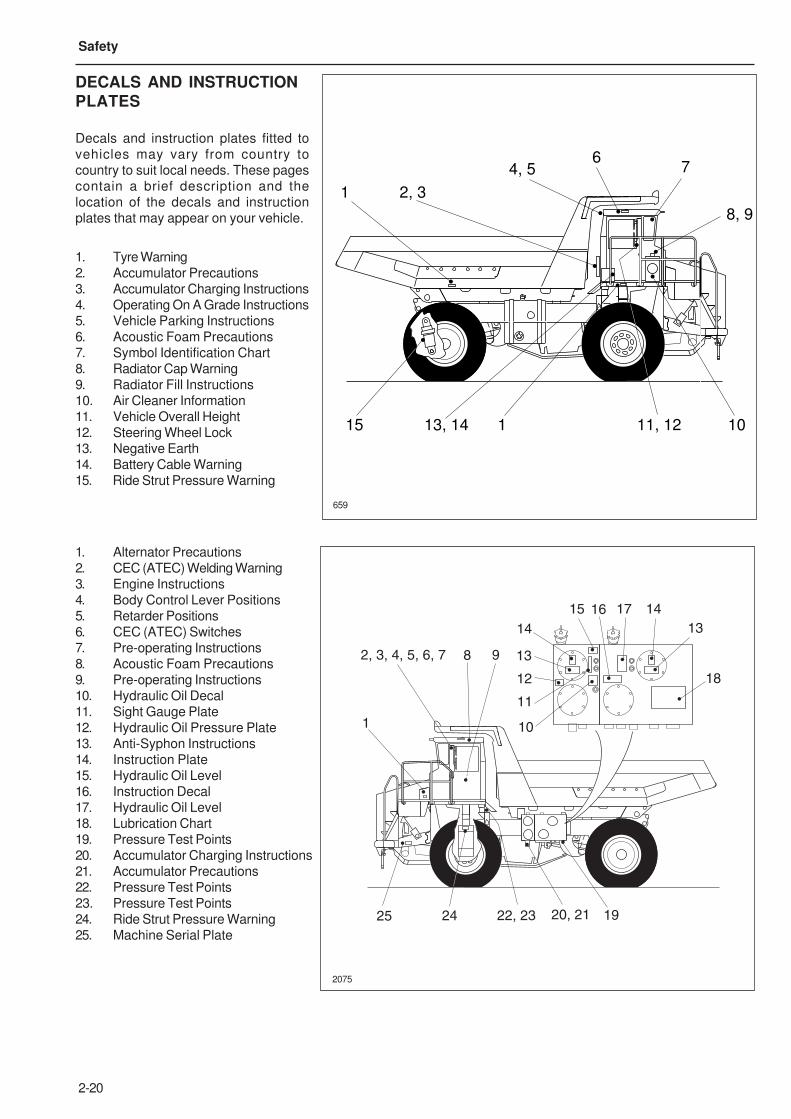
DECALS AND INSTRUCTION
PLATES
Decals and instruction plates fitted to
vehicles may vary from country to
country to suit local needs. These pages
contain a brief description and the
location of the decals and instruction
plates that may appear on your vehicle.
1. Tyre Warning
2. Accumulator Precautions
3. Accumulator Charging Instructions
4. Operating On A Grade Instructions
5. Vehicle Parking Instructions
6. Acoustic Foam Precautions
7. Symbol Identification Chart
8. Radiator Cap Warning
9. Radiator Fill Instructions
10. Air Cleaner Information
11. Vehicle Overall Height
12. Steering Wheel Lock
13. Negative Earth
14. Battery Cable Warning
15. Ride Strut Pressure Warning
1. Alternator Precautions
2. CEC (ATEC) Welding Warning
3. Engine Instructions
4. Body Control Lever Positions
5. Retarder Positions
6. CEC (ATEC) Switches
7. Pre-operating Instructions
8. Acoustic Foam Precautions
9. Pre-operating Instructions
10. Hydraulic Oil Decal
11. Sight Gauge Plate
12. Hydraulic Oil Pressure Plate
13. Anti-Syphon Instructions
14. Instruction Plate
15. Hydraulic Oil Level
16. Instruction Decal
17. Hydraulic Oil Level
18. Lubrication Chart
19. Pressure Test Points
20. Accumulator Charging Instructions
21. Accumulator Precautions
22. Pressure Test Points
23. Pressure Test Points
24. Ride Strut Pressure Warning
25. Machine Serial Plate
659
1
15 113, 14
2, 3
64, 5 7
11, 12
8, 9
10
2075
2, 3, 4, 5, 6, 7
1
8 9
10
13
11
12
14
1615 17 14
13
18
25 24 22, 23 20, 21 19
2-21
Safety
15319979
F45
(5A)
F44
(10A)
F43
(15A)
F42
(10A)
F41
(10A)
F40
(15A)
K23K23
K23
K23
K23 K23
K52 K25K48
K59
K14
NN D
TR35
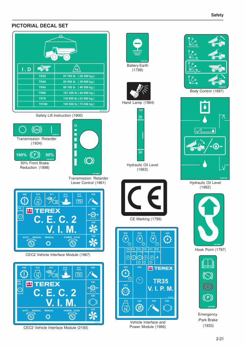
V. I. P. M.
Vehicle Interface and
Power Module (1966)
15330961
F44
(10A)
K52
K39
K20
K14 K14(AUX)
K17(AUX)
K60
AUTO MANUAL MANUAL
NN
C. E. C. 2V. I. M.
R
K17
! TV
P
POWER ECONK20
CEC2 Vehicle Interface Module (1967)
PICTORIAL DECAL SET
15335733
Hydraulic Oil Level
(1962)
15245918
TOP
Hydraulic Oil Level
(1963)
9361787
Battery Earth
(1798)
F100% 50%15335734
50% Front Brake
Reduction (1898)
Hand Lamp (1964)
15335809
E
P
Emergency
/Park Brake
(1933)
15335731
Transmission Retarder
(1934)
15335732
Body Control (1897)
I . D kg
159 500 lb ( 72 500 kg )TR100
116 850 lb ( 53 000 kg )TR70
101 200 lb ( 46 000 kg )TR60
89 100 lb ( 40 500 kg )TR45
85 800 lb ( 39 000 kg )TR40
57 760 lb ( 26 200 kg )TR35
15335767
Safety Lift Instruction (1900)
O
15318940
Transmission Retarder
Lever Control (1961)
9271069
Hook Point (1797)
CE Marking (1799)
15341437
F60
10A
K52
K39
K25
K14 K14(AUX)
K17(AUX)
K60
AUTO MANUAL MANUAL
NN
C. E. C. 2V. I. M.
R
K17
! TV
P
POWER ECONK20
CEC2 Vehicle Interface Module (2193)
2-22
Safety
15323142
F40
15A
F41
5A
K23
K23
K23
F42
5A
F43
15A
F44
15A
K59
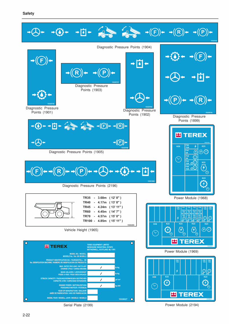
Power Module (1968)
15331024
F4015A
F4515A
F4615A
F41 F42 F43 F44
TR7015A
TR10020A
TR7015A
TR10020A
TR7015A
TR10020A
TR7015A
TR10020A
K23 K23K23 K23K59
Power Module (1969)
PRF
15335738
Diagnostic Pressure Points (1904)
15335742
P R
F
Diagnostic Pressure
Points (1899)
Diagnostic Pressure
Points (1902)
15335737
R P
Diagnostic Pressure
Points (1903)
P
RF
15335768
Diagnostic Pressure Points (1905)
15335735
F
Diagnostic Pressure
Points (1901)
15336029
F6415A
F6515A
F6615A
K23 K23K59
Power Module (2194)
PRF
15351494
Diagnostic Pressure Points (2196)
15336027
TEREX EQUIPMENT LIMITED
NEWHOUSE INDUSTRIAL ESTATE
MOTHERWELL, SCOTLAND. ML1 5RY.
MODEL NO. / MODELL
MODELE No. / No. DE MODELO
PRODUCT IDENTIFICATION NO. / FAHRGESTELL - NR
No. IDENFICATION MACHINE / NUMERO DE INDEFICACION DE PRODUCTO
MAX. RATED PAYLOAD / NUTZLAST
CHARGE UTILE / CARGA MAXIMA
MASS UNLADEN / LEERGEWIGHT
POIDS A VIDE / PESO DESCARGADO
STRUCK CAPACITY / FASSUNGSVERMOEGEN GESTRICHEN
CAPACITE A RIS / CAPACIDAD ESTANDARD
ENGINE POWER / MOTORLEISTUNG
PUISSANCE MOTEUR / POTENCIA
lb /kg
lb /kg
yd³ /m³
hp /kW
YEAR OF MANUFACTURE / BAUJAHR
ANÉE DE FABRICATION / ANO DE FABRICACION
MODEL YEAR / MODELL JAHR / MODELE / MODELO
Serial Plate (2199)
15303454
TR35
TR40
TR45
TR60
TR70
TR100
3.68m
4.17m
4.24m
4.45m
4.57m
4.85m
( 12' 8" )
( 13' 8" )
( 13' 11" )
( 14' 7" )
( 15' 0" )
( 15' 11" )
-
-
-
-
-
-
Vehicle Height (1965)
15335763
2-23
Safety
15335803
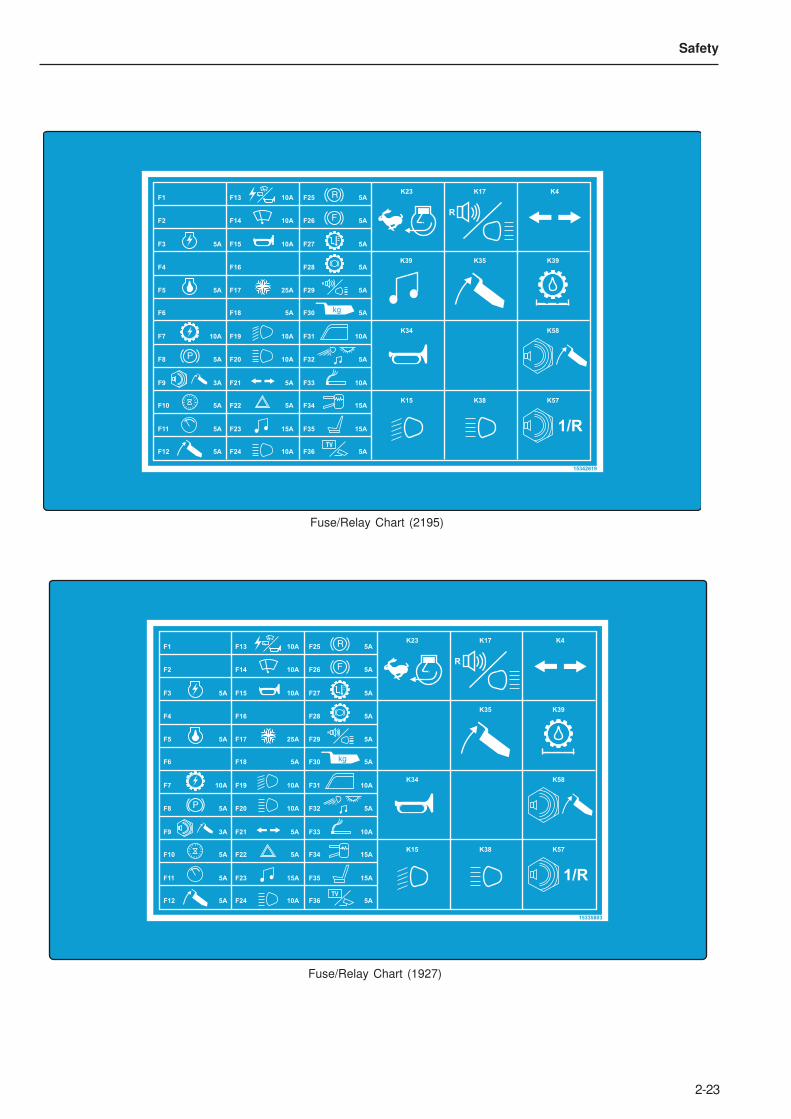
F1 F13 F25
F2 F14 F26
F3 F15 F27
F4 F16 F28
F5 F17 F29
F6 F18 F30
F7 F19 F31
F8 F20 F32
F9 F21 F33
F10 F22 F34
F11 F23 F35
F12 F24 F36
1/R
10A 5A
10A 5A
5A 10A 5A
5A
5A 25A 5A
5A 5A
10A 10A 10A
5A 10A 5A
3A 5A 10A
5A 5A 15A
5A 15A 15A
5A 10A 5A
P
R
K34
K15 K38
K58
K35 K39
K23 K17 K4
K57
R
F
R
kg
TV
Fuse/Relay Chart (2195)
15342619
F1 F13 F25
F2 F14 F26
F3 F15 F27
F4 F16 F28
F5 F17 F29
F6 F18 F30
F7 F19 F31
F8 F20 F32
F9 F21 F33
F10 F22 F34
F11 F23 F35
F12 F24 F36
1/R
10A 5A
10A 5A
5A 10A 5A
5A
5A 25A 5A
5A 5A
10A 10A 10A
5A 10A 5A
3A 5A 10A
5A 5A 15A
5A 15A 15A
5A 10A 5A
P
R
K34
K15 K38
K58
K35 K39
K23 K17 K4
K57
R
F
R
kg
TV
K39
Fuse/Relay Chart (1927)

2-24
Safety
SAFETY DECAL SET ISO STANDARD
ROPS FOPSSAE ISO SAE ISO lb MAX. kg MAX. TEREX No.
15335811
S/N
ROPS and FOPS, See handbook for procedure (1931)
30 1C 1 0.3 30 1L 10 5
25 1C 3 1 25 2 15 9
20 1L 5 3 20 3 22 14
15 1L 9 5 15 4 28 17
10 2 15 9 10 4 34 21
5 4 30 17 5 5 54 33
0 5 55 34 0 5 55 34
15335771
% KPH MPH % KPH MPH
Gradeability Chart, TR35 (1910)
15335785
Hydraulic Oil Sight
Gauge (1906)
N
15335788
P1. 2.
Warning park brake (1925)
15335864
Backalarm Warning, Operator
must make certain back alarm is
operating properly (1923)
15335820
P
30 30 1L 11 6
25 1C 5 3 25 1L 12 7
20 1C 6 3 20 2 16 9
15 1L 10 6 15 3 20 12
10 2 15 9 10 4 31 19
5 4 30 18 5 6 59 36
0 6 66 41 0 6 66 41
15335774
% KPH MPH % KPH MPH
Gradeability chart TR45 (1912)
30 1C 2 1 30 2 12 7
25 1C 5 3 25 3 15 9
20 1L 8 5 20 3 18 11
15 1L 10 6 15 4 24 15
10 3 16 10 10 5 35 21
5 5 30 18 5 6 58 36
0 6 60 37 0 6 60 37
15335776
% KPH MPH % KPH MPH
Gradeability chart, TR60 (1914)
15336277
N2
PSI / BAR
0
Suspension Strut (2198)
2-25
Safety
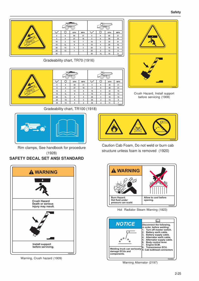
SAFETY DECAL SET ANSI STANDARD
Warning, Crush hazard (1909)
30 30 1L 10 6
25 1C 1 1 25 2 12 8
20 1C 5 3 20 3 16 10
15 1L 9 5 15 4 20 12
10 2 12 7 10 5 34 21
5 4 27 16 5 6 58 35
0 6 60 37 0 6 60 37
15335777
% KPH MPH % KPH MPH
Gradeability chart, TR70 (1916)
Gradeability chart, TR100 (1918)
15335789
Caution Cab Foam, Do not weld or burn cab
structure unless foam is removed (1920)
15335792
Rim clamps, See handbook for procedure
(1928)
15335749
Crush Hazard, Install support
before servicing (1908)
15335744
Crush HazardDeath or seriousinjury may result.
Install supportbefore servicing.
WARNING
30 30 2 11 7
25 1C 5 3
1C 4 2
25 2 14 9
20 1L 8 4 20 3 16 10
15 1L 9 5 15 4 22 13
10 2 14 9 10 5 32 19
5 4 27 16 5 6 49 31
0 6 49 31 0 6 49 31
15335778
% KPH MPH % KPH MPH
Hot Radiator Steam Warning (1823)
15335954
NOTICE
Welding truck can seriouslydamage ECUs andcomponents.
Disconnect the following,in order, before welding:1. Turn off master switch.2. Battery earth cable.3. Battery supply cable.4. Alternator earth cable.5. Alternator supply cable.6. Body control lever.7. Engine ECM.8. Transmission ECU.9. Cab bulkhead connectors
Warning Alternator (2197)
15333278
Burn Hazard.Hot fluid under pressure can scald.
Allow to cool beforeopening.
WARNING
2-26
Safety
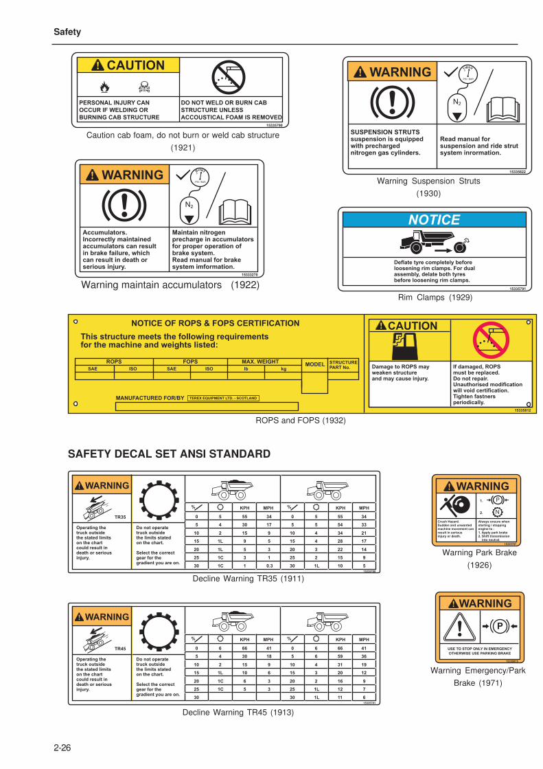
30 1C 1 0.3 30 1L 10 5
25 1C 3 1 25 2 15 9
20 1L 5 3 20 3 22 14
15 1L 9 5 15 4 28 17
10 2 15 9 10 4 34 21
5 4 30 17 5 5 54 33
0TR35 5 55 34 0 5 55 34
15335780
% KPH MPH % KPH MPH
WARNING
Operating the truck outside the stated limitson the chartcould result indeath or seriousinjury.
Do not operatetruck outsidethe limits statedon the chart.
Select the correctgear for thegradient you are on.
30 30 1L 11 6
25 1C 5 3 25 1L 12 7
20 1C 6 3 20 2 16 9
15 1L 10 6 15 3 20 12
10 2 15 9 10 4 31 19
5 4 30 18 5 6 59 36
0TR45 6 66 41 0 6 66 41
15335781
% KPH MPH % KPH MPH
Operating the truck outside the stated limitson the chartcould result indeath or seriousinjury.
Do not operatetruck outsidethe limits statedon the chart.
Select the correctgear for thegradient you are on.
WARNING
SAFETY DECAL SET ANSI STANDARD
Decline Warning TR35 (1911)
Decline Warning TR45 (1913)
15335812
CAUTIONNOTICE OF ROPS & FOPS CERTIFICATION
This structure meets the following requirementsfor the machine and weights listed:
ROPS FOPS MAX. WEIGHT
SAE ISO SAE ISO
STRUCTUREPART No.lb kg
MODEL
MANUFACTURED FOR/BY TEREX EQUIPMENT LTD. - SCOTLAND
Damage to ROPS mayweaken structureand may cause injury.
If damaged, ROPSmust be replaced.Do not repair.Unauthorised modificationwill void certification.Tighten fastnersperiodically.
ROPS and FOPS (1932)
Warning maintain accumulators (1922)
Caution cab foam, do not burn or weld cab structure
(1921)
Warning Suspension Struts
(1930)
Rim Clamps (1929)
Warning Park Brake
(1926)
Warning Emergency/Park
Brake (1971)
Accumulators.Incorrectly maintainedaccumulators can resultin brake failure, whichcan result in death or serious injury.
Maintain nitrogen precharge in accumulatorsfor proper operation ofbrake system.Read manual for brakesystem imformation.
15333270
N2
PSI / BAR
0WARNING
PERSONAL INJURY CAN
OCCUR IF WELDING OR
BURNING CAB STRUCTURE
DO NOT WELD OR BURN CAB
STRUCTURE UNLESS
ACCOUSTICAL FOAM IS REMOVED
CAUTION
15335790
Deflate tyre completely beforeloosening rim clamps. For dualassembly, delate both tyresbefore loosening rim clamps.
15335791
NOTICE
SUSPENSION STRUTSsuspension is equippedwith prechargednitrogen gas cylinders.
Read manual for suspension and ride strutsystem inrormation.
15335822
N2
PSI / BAR
0WARNING
15335815
WARNING
P
USE TO STOP ONLY IN EMERGENCY
OTHERWISE USE PARKING BRAKE
N
15335787
P1.
2.
Crush Hazard.Sudden and unwantedmachine movement canresult in seriousinjury or death.
Always ensure whenstarting / stoppingengine to :1. Apply park brake2. Shift transmission into neutral.
WARNING
2-27
Safety
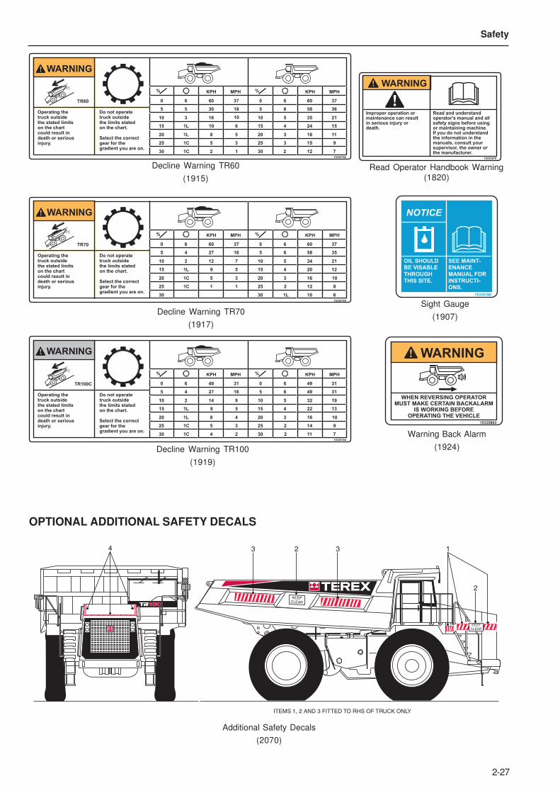
30 1C 2 1 30 2 12 7
25 1C 5 3 25 3 15 9
20 1L 8 5 20 3 18 11
15 1L 10 6 15 4 24 15
10 3 16 10 10 5 35 21
5 5 30 18 5 6 58 36
0TR60 6 60 37 0 6 60 37
15335782
% KPH MPH % KPH MPH
WARNING
Operating the truck outside the stated limitson the chartcould result indeath or seriousinjury.
Do not operatetruck outsidethe limits statedon the chart.
Select the correctgear for thegradient you are on.
30 30 1L 10 6
25 1C 1 1 25 2 12 8
20 1C 5 3 20 3 16 10
15 1L 9 5 15 4 20 12
10 2 12 7 10 5 34 21
5 4 27 16 5 6 58 35
0TR70 6 60 37 0 6 60 37
15335783
% KPH MPH % KPH MPH
Operating the truck outside the stated limitson the chartcould result indeath or seriousinjury.
Do not operatetruck outsidethe limits statedon the chart.
Select the correctgear for thegradient you are on.
WARNING
30 30 2 11 7
25 1C 5 3
1C 4 2
25 2 14 9
20 1L 8 4 20 3 16 10
15 1L 9 5 15 4 22 13
10 2 14 9 10 5 32 19
5 4 27 16 5 6 49 31
0TR100C 6 49 31 0 6 49 31
15335784
% KPH MPH % KPH MPH
Operating the truck outside the stated limitson the chartcould result indeath or seriousinjury.
Do not operatetruck outsidethe limits statedon the chart.
Select the correctgear for thegradient you are on.
WARNING
Decline Warning TR60
(1915)
Decline Warning TR70
(1917)
Decline Warning TR100
(1919)
OPTIONAL ADDITIONAL SAFETY DECALS
Additional Safety Decals
(2070)
4
KEEP
CLEAR
KEEP
CLEAR
3 2 3
2
1
ITEMS 1, 2 AND 3 FITTED TO RHS OF TRUCK ONLY
Read Operator Handbook Warning
(1820)
Warning Back Alarm
(1924)
15335863
WHEN REVERSING OPERATORMUST MAKE CERTAIN BACKALARM
IS WORKING BEFOREOPERATING THE VEHICLE
WARNING
15333275
Improper operation ormaintenance can resultin serious injury ordeath.
Read and understandoperator's manual and allsafety signs before using or maintaining machine.If you do not understandthe information in the manuals, consult yoursupervisor, the owner or the manufacturer.
WARNING
15335786
NOTICE
OIL SHOULDBE VISABLETHROUGHTHIS SITE.
SEE MAINT-ENANCEMANUAL FORINSTRUCTI-ONS.
Sight Gauge
(1907)

2-28
Safety
This Page Intentionally Left Blank

3-1
3 - Controls and Operating

3-2
Controls and Operating
This Page Intentionally Left Blank
3-3
Controls and Operating
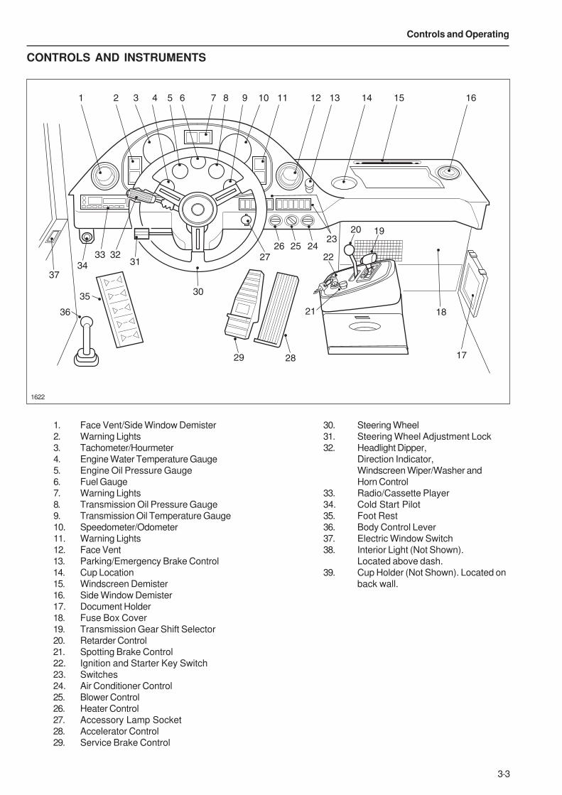
CONTROLS AND INSTRUMENTS
1622
1. Face Vent/Side Window Demister
2. Warning Lights
3. Tachometer/Hourmeter
4. Engine Water Temperature Gauge
5. Engine Oil Pressure Gauge
6. Fuel Gauge
7. Warning Lights
8. Transmission Oil Pressure Gauge
9. Transmission Oil Temperature Gauge
10. Speedometer/Odometer
11. Warning Lights
12. Face Vent
13. Parking/Emergency Brake Control
14. Cup Location
15. Windscreen Demister
16. Side Window Demister
17. Document Holder
18. Fuse Box Cover
19. Transmission Gear Shift Selector
20. Retarder Control
21. Spotting Brake Control
22. Ignition and Starter Key Switch
23. Switches
24. Air Conditioner Control
25. Blower Control
26. Heater Control
27. Accessory Lamp Socket
28. Accelerator Control
29. Service Brake Control
30. Steering Wheel
31. Steering Wheel Adjustment Lock
32. Headlight Dipper,
Direction Indicator,
Windscreen Wiper/Washer and
Horn Control
33. Radio/Cassette Player
34. Cold Start Pilot
35. Foot Rest
36. Body Control Lever
37. Electric Window Switch
38. Interior Light (Not Shown).
Located above dash.
39. Cup Holder (Not Shown). Located on
back wall.
1 2 3 4 5 6 7 8 9 10 11 12 13 14 15 16
17
18
1920
22
23242526
27
2829
30
313233
34
35
36
37
21
3-4
Controls and Operating
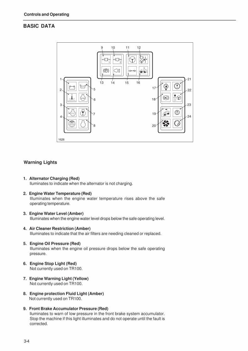
BASIC DATA
1. Alternator Charging (Red)lluminates to indicate when the alternator is not charging.
2. Engine Water Temperature (Red)Illuminates when the engine water temperature rises above the safe
operating temperature.
3. Engine Water Level (Amber)Illuminates when the engine water level drops below the safe operating level.
4. Air Cleaner Restriction (Amber)Illuminates to indicate that the air filters are needing cleaned or replaced.
5. Engine Oil Pressure (Red)Illuminates when the engine oil pressure drops below the safe operating
pressure.
6. Engine Stop Light (Red)Not currently used on TR100.
7. Engine Warning Light (Yellow)Not currently used on TR100.
8. Engine protection Fluid Light (Amber)Not currently used on TR100.
9. Front Brake Accumulator Pressure (Red)lluminates to warn of low pressure in the front brake system accumulator.
Stop the machine if this light illuminates and do not operate until the fault is
corrected.
1626
STOP
P
1 2
1
2
3
4
5
6
7
8
9 10 11 12
13 14 15 16
17
18
19
20
21
22
23
24
Warning Lights
3-5
Controls and Operating
10. Rear Brake Accumulator Pressure (Red)Illuminates to warn of low pressure in the rear brake system accumulator. Stop the
machine if this light illuminates and do not operate until the fault is corrected.
11. Low Steering Pressure (Red)Illuminates when the steering system oil pressure drops below 83 bar (1200 lbf/in²).
Stop the machine when this light illuminates and do not operate until the fault is
corrected.
12. Steering & Braking Tank Low Oil Level (Red)Illuminates when the level in the tank falls below the safe operating level. Stop the
machine when this light illuminates and do not operate until the fault is corrected.
13. Parking Brake (Green)Illuminates when the parking brake is applied.
14. Headlight Main Beam (Blue)Illuminates when headlights are operated on main beam.
15. Direction Indicator (Green)Flashes when the indicator lights are operating.
16. Body-up (Amber)Illuminates to indicate that the body is NOT resting on the chassis. Never move the
machine until this light goes OUT.
17. Transmission Oil Temperature (Red)Illuminates when the transmission oil temperature rises above the safe operating
temperature.
18. Brake Hydraulic Oil Temperature (Red)Illuminates if brake cooling hydraulic oil overheats. Reduce speed and shift
transmission to the range that will maintain an engine speed as high as possible,
without exceeding the maximum recommendation, to increase oil circulation and
cooling. If the trouble persists, stop the machine and have the fault corrected.
19. Retarder Indicator (Amber)Illuminates when the retarder is applied.
20. In-converter Indicator (Green)Illuminates when the transmission is in Torque Converter drive. It goes OUT when
Lockup is engaged.
21. Check Trans (Red)Illuminates to alert of a fault in the transmission shift system or abnormal
transmission temperature. The light will illuminate when the ignition keyswitch is
turned to position '1' to provide a bulb and system check and should go off a few
seconds after the engine is started.
22. Steering Filter Restriction (Amber)Illuminates when the filter is restricted, indicating that a filter change is required.
23. Transmission Oil Filter Restriction (Amber)Illuminates when the filter is restricted, indicating that a filter change is required.
Transmission will not upshift from first gear while this light is illuminated.
Note: This lamp may illuminate at initial start up, due to the viscosity of the oil
when cold.

3-6
Controls and Operating
24. Engine Overspeed (Red)Illuminates to alert the operator when the transmission ECU detects an
engine speed of 2550 rev/min.
Note: For further information on items 21 and 24, refer to ‘ Transmission’ section
on pages 3-23 and 3-24.
3-7
Controls and Operating
1387
0
5
1015
20
25
RPM x100
30
STOP
ENGWATER TEMP
ENGOIL PRESS
P
1 2
2
13
4
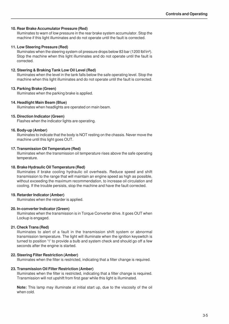
INSTRUMENTS
1. Tachometer/HourmeterIndicates the engine speed in revolutions per minute. The
needle shows the variations in engine operating speed.
Never accelerate the engine to speeds indicated by the red
zone on the dial face. A digital hourmeter is incorporated in
the tachometer to record total hours of engine operation.
The readings can be used for operating and service records.
2. Engine Water Temperature GaugeThis gauge should read in the green zone, after the engine
has warmed. If gauge reads in the red zone, stop the
engine until the fault is corrected.
3. Engine Oil Pressure GaugeThis gauge should read in the lower end of the green zone
at normal operating speeds (on machines with three colour
zone, may fall to the lower end of the yellow zone at engine
idle). If gauge reads in the red zone, stop the engine until
the fault is corrected.
4. Fuel GaugeIndicates the level in the fuel tank. Fill the tank before
parking the machine overnight to minimize condensation in
the tank. Avoid a dry tank condition which requires bleeding
the fuel system.
5. Transmission Oil Pressure GaugeIndicates transmission clutch application oil pressure. Thereading will vary during shifts and with varying speeds and
loads. The needle should remain in the green zone during
normal operation but might rise into the upper red zone for
short periods under heavy loading. When the load decreases,
the needle should return to the green zone and may fall
momentarily into the lower red zone. If the needle remains
in either of the extreme zones for extended periods, stop
the machine until the fault is corrected.
6. Transmission Oil Temperature GaugeThis gauge should read in the green zone during normal
operation. Refer also to 'General Transmission Operation'
on page 3-24 and 'Retarder' section on page 3-14 for
variations from normal.
7. Speedometer/OdometerDriven by a signal from the transmission ECU, the
speedometer indicates travel speed in kilometres per hour
and miles per hour. A digital odometer is incorporated in the
speedometer to record the distance travelled by the
vehicle at any given time.
1629
0
10
3020
40
km/h
50
MPH20
20
20
20
OIL TEMP
TRANS50 150
120140
OIL PRESSTRANS
P
1 2
5
7
6
3-8
Controls and Operating
VIEW ON FRONT OF INTERFACE BOX
1479
MANUAL AUTO POWER ECONOMY
1413
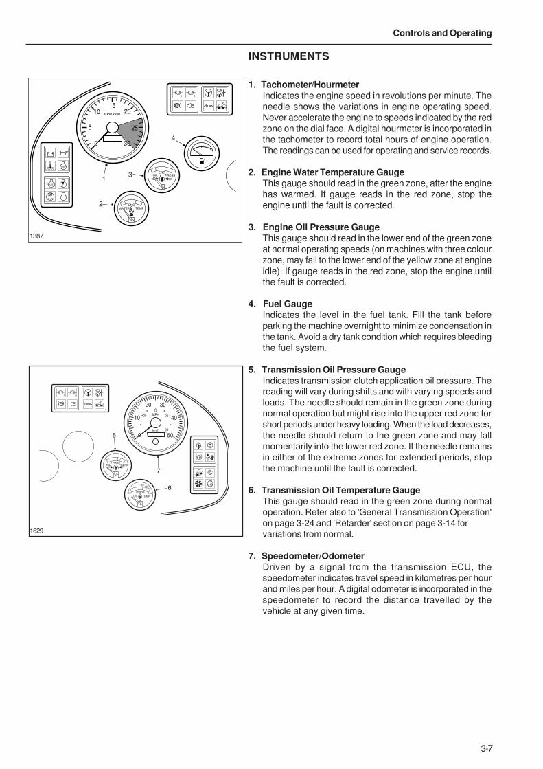
SWITCHES
1. Hazard Warning LightsPress bottom of switch to make turn indicators flash simultaneously as
hazard warning lights. The light in the switch and direction indicator warning
light on the dash panel will flash. To switch hazard lights off; press the top of
the switch.
2. Position not used.
3. Position not used.
4. Position not used.
5. Front Brake Pressure ReductionPress bottom of switch to give a 50% reduction in front brake pressure. The
lower front pressure reduces the risk of wheel lockup in slippery conditions.
To return to full front brake pressure; press the top of the switch.
6. Retarder Selection SwitchAllows the operator to select which retarder is employed when using the
retarder control lever.
Pressed at top = Disc Brake
Pressed at bottom = Transmission
7. Sidelight and HeadlightPress bottom of switch to the first position to operate side, tail and panel
lights. The lights in the other switches will illuminate. Press switch to the
second position to operate the headlights. To switch lights off; press the top
of the switch.
8. Position not used.
9. Warning Light Test SwitchPressing the switch with the ignition switched on will illuminate warning lights
1, 2, 3, 4, 5, 9, 10, 11, 12, 17, 18, 20, 22 and 23 and the buzzer will sound,
to provide a bulb and system check. Refer to 'Warning Lights' section on
pages 3-4, 3-5 and 3-6 for details. The light in the switch will illuminate with
the panel lights.
10. Position not used.
11. Position not used.
12. Position not used.
13. Manual Mode SwitchAllows the service technician to change the operation of the transmission
from automatic to manual.
Automatic - Normal Operation.
Manual - Service Functions.
14. Mode Selection SwitchAllows the service technician to select between the transmission 'POWER'
and 'ECONOMY' shift schedules.
2237 Right Hand Panel
Left Hand Panel2236
HAZARD 50%(0)
1 2 3 4 5 6
TEST
7 8 9 10 11 12
3-9
Controls and Operating
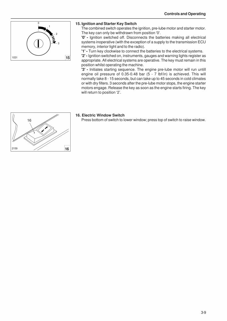
15. Ignition and Starter Key SwitchThe combined switch operates the ignition, pre-lube motor and starter motor.
The key can only be withdrawn from position '0'.
'0' - Ignition switched off. Disconnects the batteries making all electrical
systems inoperative (with the exception of a supply to the transmission ECU
memory, interior light and to the radio).
'1' - Turn key clockwise to connect the batteries to the electrical systems.
'2' - Ignition switched on, instruments, gauges and warning lights register as
appropriate. All electrical systems are operative. The key must remain in this
position whilst operating the machine.
'3' - Initiates starting sequence. The engine pre-lube motor will run untill
engine oil pressure of 0.35-0.48 bar (5 - 7 lbf/in) is achieved. This will
normally take 8 - 15 seconds, but can take up to 45 seconds in cold climates
or with dry filters. 3 seconds after the pre-lube motor stops, the engine starter
motors engage. Release the key as soon as the engine starts firing. The key
will return to position ‘2’.
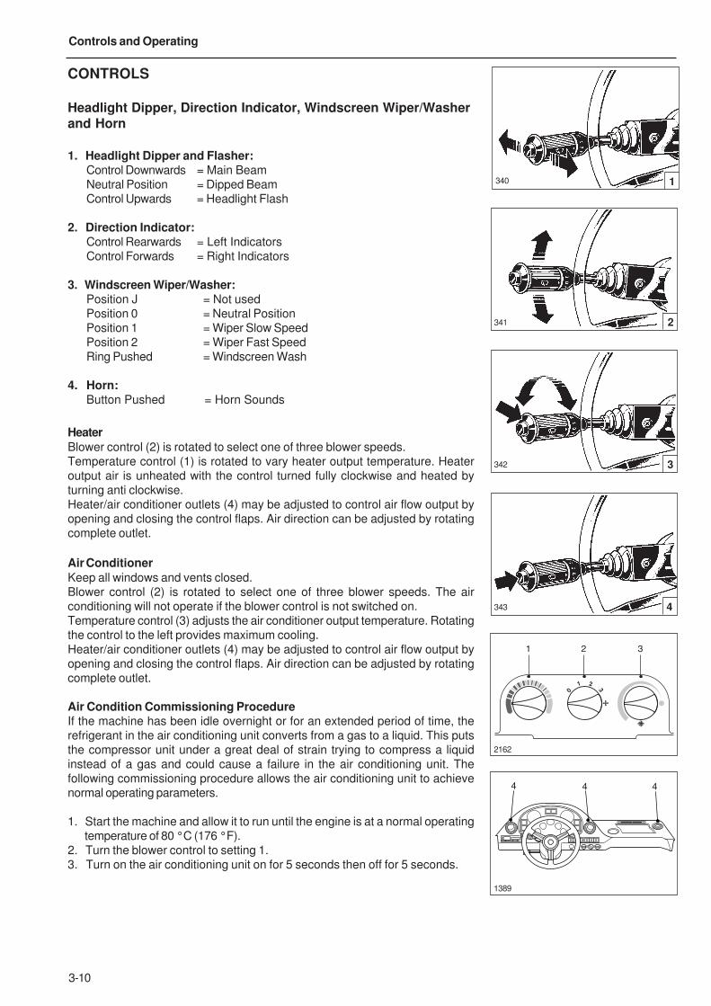
16. Electric Window SwitchPress bottom of switch to lower window; press top of switch to raise window.
0
1
2
3
1031 15
16
2159 16
3-10
Controls and Operating
CONTROLS
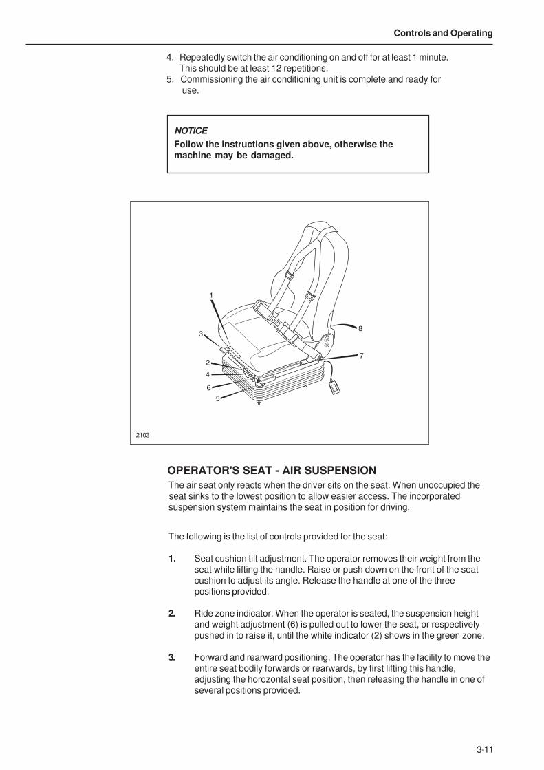
Headlight Dipper, Direction Indicator, Windscreen Wiper/Washer
and Horn
1. Headlight Dipper and Flasher:Control Downwards = Main Beam
Neutral Position = Dipped Beam
Control Upwards = Headlight Flash
2. Direction Indicator:Control Rearwards = Left Indicators
Control Forwards = Right Indicators
3. Windscreen Wiper/Washer:Position J = Not used
Position 0 = Neutral Position
Position 1 = Wiper Slow Speed
Position 2 = Wiper Fast Speed
Ring Pushed = Windscreen Wash
4. Horn:Button Pushed = Horn Sounds
Heater
Blower control (2) is rotated to select one of three blower speeds.
Temperature control (1) is rotated to vary heater output temperature. Heater
output air is unheated with the control turned fully clockwise and heated by
turning anti clockwise.
Heater/air conditioner outlets (4) may be adjusted to control air flow output by
opening and closing the control flaps. Air direction can be adjusted by rotating
complete outlet.
Air Conditioner
Keep all windows and vents closed.
Blower control (2) is rotated to select one of three blower speeds. The air
conditioning will not operate if the blower control is not switched on.
Temperature control (3) adjusts the air conditioner output temperature. Rotating
the control to the left provides maximum cooling.
Heater/air conditioner outlets (4) may be adjusted to control air flow output by
opening and closing the control flaps. Air direction can be adjusted by rotating
complete outlet.
Air Condition Commissioning ProcedureIf the machine has been idle overnight or for an extended period of time, the
refrigerant in the air conditioning unit converts from a gas to a liquid. This puts
the compressor unit under a great deal of strain trying to compress a liquid
instead of a gas and could cause a failure in the air conditioning unit. The
following commissioning procedure allows the air conditioning unit to achieve
normal operating parameters.
1. Start the machine and allow it to run until the engine is at a normal operating
temperature of 80 °C (176 °F).
2. Turn the blower control to setting 1.
3. Turn on the air conditioning unit on for 5 seconds then off for 5 seconds.
340 1
341 2
342 3
343 4
2162
1389
4 4 4
1
0
2
3
1 2 3
3-11
Controls and Operating
2103
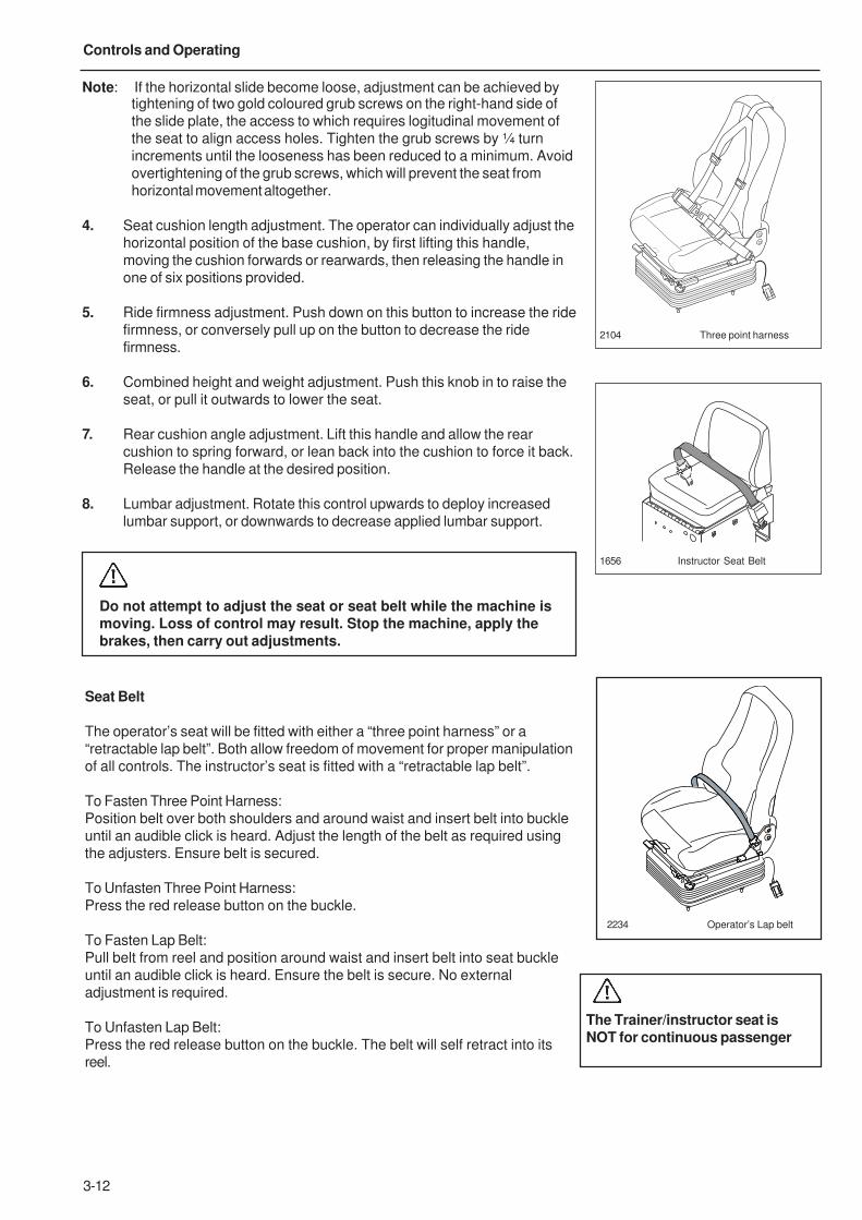
The following is the list of controls provided for the seat:
1. Seat cushion tilt adjustment. The operator removes their weight from the
seat while lifting the handle. Raise or push down on the front of the seat
cushion to adjust its angle. Release the handle at one of the three
positions provided.
2. Ride zone indicator. When the operator is seated, the suspension height
and weight adjustment (6) is pulled out to lower the seat, or respectively
pushed in to raise it, until the white indicator (2) shows in the green zone.
3. Forward and rearward positioning. The operator has the facility to move the
entire seat bodily forwards or rearwards, by first lifting this handle,
adjusting the horozontal seat position, then releasing the handle in one of
several positions provided.
4. Repeatedly switch the air conditioning on and off for at least 1 minute.
This should be at least 12 repetitions.
5. Commissioning the air conditioning unit is complete and ready for
use.
1
2
3
4
5
6
7
8
OPERATOR'S SEAT - AIR SUSPENSION
The air seat only reacts when the driver sits on the seat. When unoccupied the
seat sinks to the lowest position to allow easier access. The incorporated
suspension system maintains the seat in position for driving.
NOTICE
Follow the instructions given above, otherwise themachine may be damaged.
3-12
Controls and Operating
2104 Three point harness
1656 Instructor Seat Belt
Do not attempt to adjust the seat or seat belt while the machine ismoving. Loss of control may result. Stop the machine, apply thebrakes, then carry out adjustments.
Note: If the horizontal slide become loose, adjustment can be achieved bytightening of two gold coloured grub screws on the right-hand side of
the slide plate, the access to which requires logitudinal movement of
the seat to align access holes. Tighten the grub screws by ¼ turn
increments until the looseness has been reduced to a minimum. Avoid
overtightening of the grub screws, which will prevent the seat from
horizontal movement altogether.
4. Seat cushion length adjustment. The operator can individually adjust the
horizontal position of the base cushion, by first lifting this handle,
moving the cushion forwards or rearwards, then releasing the handle in
one of six positions provided.
5. Ride firmness adjustment. Push down on this button to increase the ride
firmness, or conversely pull up on the button to decrease the ride
firmness.
6. Combined height and weight adjustment. Push this knob in to raise the
seat, or pull it outwards to lower the seat.
7. Rear cushion angle adjustment. Lift this handle and allow the rear
cushion to spring forward, or lean back into the cushion to force it back.
Release the handle at the desired position.
8. Lumbar adjustment. Rotate this control upwards to deploy increased
lumbar support, or downwards to decrease applied lumbar support.
Seat Belt
The operator’s seat will be fitted with either a “three point harness” or a
“retractable lap belt”. Both allow freedom of movement for proper manipulation
of all controls. The instructor’s seat is fitted with a “retractable lap belt”.
To Fasten Three Point Harness:
Position belt over both shoulders and around waist and insert belt into buckle
until an audible click is heard. Adjust the length of the belt as required using
the adjusters. Ensure belt is secured.
To Unfasten Three Point Harness:
Press the red release button on the buckle.
To Fasten Lap Belt:
Pull belt from reel and position around waist and insert belt into seat buckle
until an audible click is heard. Ensure the belt is secure. No external
adjustment is required.
To Unfasten Lap Belt:
Press the red release button on the buckle. The belt will self retract into its
reel.
The Trainer/instructor seat isNOT for continuous passenger
2234 Operator’s Lap belt
3-13
Controls and Operating
Always wear the seat belt when operating the machine.
Always check condition of seat belts and mounting hardwarebefore operating the machine.
Any signs of looseness or wear should be reported to yourMainenance Department or Dealer for repair or replacement imme-diately.
Replace seat belts at least once every three years, regardless ofappearance.
Do not attempt to adjust seat or seat belt while machine is moving.Loss of control may result. Stop machine; apply brakes; thenadjust.
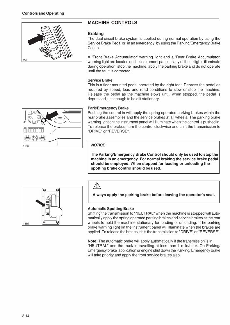
3-14
Controls and Operating
MACHINE CONTROLS
BrakingThe dual circuit brake system is applied during normal operation by using the
Service Brake Pedal or, in an emergency, by using the Parking/Emergency Brake
Control.
A 'Front Brake Accumulator' warning light and a 'Rear Brake Accumulator'
warning light are located on the instrument panel. If any of these lights illuminate
during operation, stop the machine, apply the parking brake and do not operate
until the fault is corrected.
Service BrakeThis is a floor mounted pedal operated by the right foot. Depress the pedal as
required by speed, load and road conditions to slow or stop the machine.
Release the pedal as the machine slows until, when stopped, the pedal is
depressed just enough to hold it stationary.
Park/Emergency BrakePushing the control in will apply the spring operated parking brakes within the
rear brake assemblies and the service brakes at all wheels. The parking brake
warning light on the instrument panel will illuminate when the control is pushed in.
To release the brakes; turn the control clockwise and shift the transmission to
"DRIVE" or "REVERSE".
NOTICE
The Parking/Emergency Brake Control should only be used to stop themachine in an emergency. For normal braking the service brake pedalshould be employed. When stopped for loading or unloading thespotting brake control should be used.
Always apply the parking brake before leaving the operator's seat.
Automatic Spotting BrakeShifting the transmission to "NEUTRAL" when the machine is stopped will auto-
matically apply the spring operated parking brakes and service brakes at the rear
wheels to hold the machine stationary for loading or unloading. The parking
brake warning light on the instrument panel will illuminate when the brakes are
applied. To release the brakes, shift the transmission to "DRIVE" or "REVERSE".
Note: The automatic brake will apply automatically if the transmission is in
"NEUTRAL" and the truck is travelling at less than 1 mile/hour. On Parking/
Emergency brake application or engine shut down the Parking/ Emergency brake
will take priority and apply the front service brakes also.
251
1106
1485
MODE
1
2
3
4
5
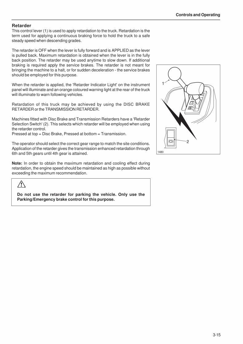
3-15
Controls and Operating
1480
RetarderThis control lever (1) is used to apply retardation to the truck. Retardation is the
term used for applying a continuous braking force to hold the truck to a safe
steady speed when descending grades.
The retarder is OFF when the lever is fully forward and is APPLIED as the lever
is pulled back. Maximum retardation is obtained when the lever is in the fully
back position. The retarder may be used anytime to slow down. If additional
braking is required apply the service brakes. The retarder is not meant for
bringing the machine to a halt, or for sudden deceleration - the service brakes
should be employed for this purpose.
When the retarder is applied, the 'Retarder Indicator Light' on the instrument
panel will illuminate and an orange coloured warning light at the rear of the truck
will illuminate to warn following vehicles.
Retardation of this truck may be achieved by using the DISC BRAKE
RETARDER or the TRANSMISSION RETARDER.
Machines fitted with Disc Brake and Transmission Retarders have a 'Retarder
Selection Switch' (2). This selects which retarder will be employed when using
the retarder control.
Pressed at top = Disc Brake, Pressed at bottom = Transmission.
The operator should select the correct gear range to match the site conditions.
Application of the retarder gives the transmission enhanced retardation through
6th and 5th gears until 4th gear is attained.
Note: In order to obtain the maximum retardation and cooling effect during
retardation, the engine speed should be maintained as high as possible without
exceeding the maximum recommendation.
Do not use the retarder for parking the vehicle. Only use theParking/Emergency brake control for this purpose.
1
2
3
4
5
D
N
R1
R2
1
2
3-16
Controls and Operating
Retarder OperationBefore the machine crests the top of a grade and starts down, the operator
should slow the machine with the service brakes and downshift to the gear range
which would be used to ascend the grade. The retarder should be applied before
starting the descent. Machine downgrade speed (with the retarder applied as
required) in the gear range selected should be high enough to keep the engine
operating at governed speed with the throttle closed (operator's foot off the
accelerator pedal). This will ensure maximum oil circulation and cooling. If the
rate of descent is too slow, the transmission should be upshifted to the next
highest gear range. If the rate of descent is too fast, the gear range selected is
too high and the operator must slow the machine by using the service brakes,
then downshift into a lower gear range which will allow a safe descent and
efficient retarder operation.
Great care should be used if applying the retarder when roadsurfaces are slippery. Retarder braking effect will occur only at thedriving axle and could make vehicle control difficult.
Oil Temperature - Disc Brake
The disc brake hydraulic temperature warning light on the instrument panel will
illuminate and an electric horn will sound if the oil flowing through the disc brake
assemblies overheats. If alarm is activated, reduce downgrade travel speed. If
the trouble persists, stop the machine and have the fault corrected.
Oil Temperature - Transmission
During normal operation the transmission oil temperature gauge should read in
the green zone. However, during transmission retarder operation oil temperature
can enter the yellow 'RETARDER ON' zone but should not enter the red zone. Do
not allow the temperature to stay at or near the top of the yellow zone for more
than 3 minutes. Reduce downgrade travel speed to avoid the oil overheating and
possible damage to the transmission.
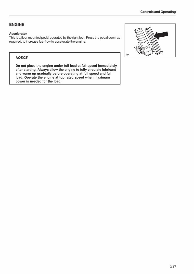
3-17
Controls and Operating
ENGINE
AcceleratorThis is a floor mounted pedal operated by the right foot. Press the pedal down as
required, to increase fuel flow to accelerate the engine.
NOTICE
Do not place the engine under full load at full speed immediatelyafter starting. Always allow the engine to fully circulate lubricantand warm up gradually before operating at full speed and fullload. Operate the engine at top rated speed when maximumpower is needed for the load.
255
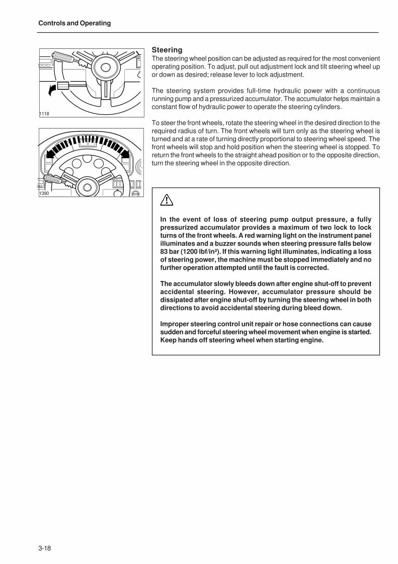
3-18
Controls and Operating
SteeringThe steering wheel position can be adjusted as required for the most convenient
operating position. To adjust, pull out adjustment lock and tilt steering wheel up
or down as desired; release lever to lock adjustment.
The steering system provides full-time hydraulic power with a continuous
running pump and a pressurized accumulator. The accumulator helps maintain a
constant flow of hydraulic power to operate the steering cylinders.
To steer the front wheels, rotate the steering wheel in the desired direction to the
required radius of turn. The front wheels will turn only as the steering wheel is
turned and at a rate of turning directly proportional to steering wheel speed. The
front wheels will stop and hold position when the steering wheel is stopped. To
return the front wheels to the straight ahead position or to the opposite direction,
turn the steering wheel in the opposite direction.
In the event of loss of steering pump output pressure, a fullypressurized accumulator provides a maximum of two lock to lockturns of the front wheels. A red warning light on the instrument panelilluminates and a buzzer sounds when steering pressure falls below83 bar (1200 lbf/in²). If this warning light illuminates, indicating a lossof steering power, the machine must be stopped immediately and nofurther operation attempted until the fault is corrected.
The accumulator slowly bleeds down after engine shut-off to preventaccidental steering. However, accumulator pressure should bedissipated after engine shut-off by turning the steering wheel in bothdirections to avoid accidental steering during bleed down.
Improper steering control unit repair or hose connections can causesudden and forceful steering wheel movement when engine is started.Keep hands off steering wheel when starting engine.
1118
1390
3-19
Controls and Operating
TransmissionThis machine is equipped with a CEC (Commercial Electronic Control) shift sys-
tem, to operate the transmission. The CEC shift system continually
monitors the transmission and shift system electrical components and warns
the operator when a problem develops. It also takes action to prevent damage to
the transmission, and provides the serviceman with diagnostic capabilities so
that problems can be corrected quickly and easily.
NOTICE
Before any welding is done on a machine equipped with a CEC shiftsystem, disconnect battery equalizer ground cables, battery cablesfrom terminal posts (ground cable first), battery equalizer positivecables and electrical connections at the ECU to avoid damageelectrical components. Turn off ignition key switch toisolate batteries before disconnecting any components.
In addition, CEC provides the following systems designed to protect the
operator and mechanical components:
REVERSE INHIBITPrevents gear selection if engine is operating at more than 20% throttle.
HOIST INTERLOCK PRESSURE SWITCHThe ECU will shift the transmission from Reverse to Neutral if the body control
lever is moved to the 'Raise' position. When this circuit has been activated,
moving the transmission shift lever to Neutral, the re-selecting Reverse, will en-
gage Reverse gear whilst the body is held in the 'Raise' position. This feature is
only operational in the normal automatic driving mode, either power or economy.It is not activated during the manual mode.
NOTICE
The standard procedure for raising the body must still be adheredto.
BODY UP INTERLOCKWhen the body is raised, the CEC system will only allow the transmission to
operate in First gear. This feature is only operational in the normal automatic
driving mode, either power or economy. It is not activated during the manual
mode.
PARKING BRAKE INTERLOCKIf the parking brake control switch is applied while the transmission is in Neutral,
the CEC system will prevent a shift out of Neutral to protect the brake
components. If the parking brake control switch is applied while the transmis-
sion is in gear, the parking brake interlock will not function and normal shifts will
occur.
3-20
Controls and Operating
LOCK-IN-GEARThe lock-in-gear feature is designed to protect the transmission from damage
should wheel spinning or lockup occur due to poor traction or panic braking. The
ECU will delay making a shift for several seconds and then, if the condition fails
to correct itself, locks in gear and prevents any further shifting. The Check Trans
warning light will come on. If this occurs, the ECU must be reset before normal
operation may be resumed.
To reset the ECU if the transmission has locked in gear because of wheel
spinning or a panic stop, stop the machine, select 'Neutral', apply the parking
brake contorl switch, and shut down the engine. Wait ten seconds, then restart
the engine. Select 'Reverse', then 'Neutral'. The Check Trans warning light should
go 'Off'.
COLD WEATHER STARTSDuring cold weather starts, if the transmission temperature is below
-24° C (-10° F) the Check Trans warning light will illuminate and the ECU will
prevent the transmission from being shifted out of Neutral.
Between -24° C (-10° F) and -7° C (19° F) the light will go out and the ECU will
only permit operation in First or Reverse gears. Above -7° C (19° F), normal
operation will be permitted.
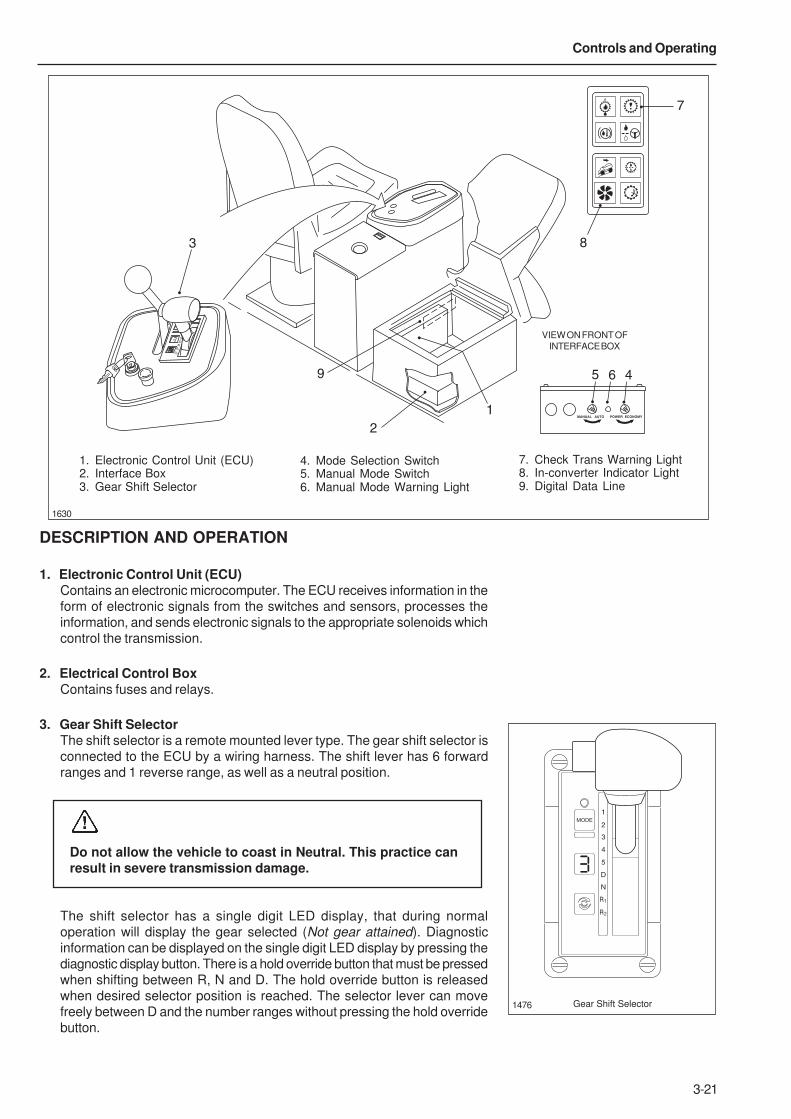
3-21
Controls and Operating
MANUAL AUTO POWER ECONOMY
1
2
3
4
5
D
N
R1
R2
7
3
9
1
2
8
5 46
1630
VIEW ON FRONT OF
INTERFACE BOX
DESCRIPTION AND OPERATION
1. Electronic Control Unit (ECU)Contains an electronic microcomputer. The ECU receives information in the
form of electronic signals from the switches and sensors, processes the
information, and sends electronic signals to the appropriate solenoids which
control the transmission.
2. Electrical Control BoxContains fuses and relays.
3. Gear Shift SelectorThe shift selector is a remote mounted lever type. The gear shift selector is
connected to the ECU by a wiring harness. The shift lever has 6 forward
ranges and 1 reverse range, as well as a neutral position.
Do not allow the vehicle to coast in Neutral. This practice canresult in severe transmission damage.
The shift selector has a single digit LED display, that during normal
operation will display the gear selected (Not gear attained). Diagnostic
information can be displayed on the single digit LED display by pressing the
diagnostic display button. There is a hold override button that must be pressed
when shifting between R, N and D. The hold override button is released
when desired selector position is reached. The selector lever can move
freely between D and the number ranges without pressing the hold override
button.
Gear Shift Selector1476
1. Electronic Control Unit (ECU)2. Interface Box3. Gear Shift Selector
4. Mode Selection Switch5. Manual Mode Switch6. Manual Mode Warning Light
7. Check Trans Warning Light8. In-converter Indicator Light9. Digital Data Line
1
2
3
4
5
D
N
R
MODE
1
R2
3-22
Controls and Operating
The transmission provides six forward ranges, one reverse range and a neutral
position. The transmission upshifts and downshifts automatically between first
range and the highest range selected on the range selector in direct response to
throttle position and transmission output speed.
When reverse range is selected the 'Reverse Alarm' sounds and the 'Reverse
Light' illuminates at the rear of the truck. This feature warns personnel to the
immediate rear of the truck that the operator has shifted the transmission to
reverse.
When drive (D) is selected, the transmission automatically upshifts and downshifts
through all six forward ranges as required by loads and travel speeds. Selecting
a lower range (4th, 3rd etc.) limits the highest range to which the transmission
will automatically upshift.
If a lower range is selected while moving forward, the transmission
automatically downshifts sequentially to the selected lower range at maximum
controlled engine speeds. Downshifts will not occur until machine is slowed by
use of the service brakes and/or retarder.
When shifting from neutral to start from a standstill, or to reverse direction,
decelerate the engine to idle speed. To move forward, select Drive (D) and
accelerate the engine to the machine load and speed requirements. The
transmission will automatically upshift from 1st through 6th ranges as travel
speed increases.
With the throttle fully depressed, and the Mode Selection Switch in the 'POWER'
position, the transmission upshifts to the next higher range when the engine
attains maximum rated speed, since maximum power train output is needed
under this condition. At lower throttle settings where minimum power train
performance is required, the transmission will upshift to the next higher range at
less than maximum rated engine speed.
Upgrades or soft spots might slow travel speed, even at full throttle, requiring
transmission downshifts to maintain maximum powertrain performance. When
this occurs, the transmission downshifts automatically.
Shift the transmission to the next lowest range if transmission 'Hunting' or 'Shift
Cycling' occurs.
When temporarily stopped, such as for yielding the right-of-way to a loaded
machine, the transmission can be left in the selected range and the machine
held stationary with the service brakes.
When stopped for a more extended period with the engine left running, however,
shift the transmission to Neutral to avoid unnecessary heat buildup, and apply
the parking brake.
Always select neutral and apply the parking brake before leavingthe operator's seat.
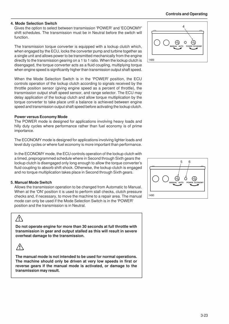
3-23
Controls and Operating
4. Mode Selection SwitchGives the option to select between transmission 'POWER' and 'ECONOMY'
shift schedules. The transmission must be in Neutral before the switch will
function.
The transmission torque converter is equipped with a lockup clutch which,
when engaged by the ECU, locks the converter pump and turbine together as
a single unit and allows power to be transmitted mechanically from the engine
directly to the transmission gearing on a 1 to 1 ratio. When the lockup clutch is
disengaged, the torque converter acts as a fluid coupling, multiplying torque
when engine speed is significantly higher than transmission output shaft speed.
When the Mode Selection Switch is in the 'POWER' position, the ECU
controls operation of the lockup clutch according to signals received by the
throttle position sensor (giving engine speed as a percent of throttle), the
transmission output shaft speed sensor, and range selector. The ECU may
delay application of the lockup clutch and allow torque multiplication by the
torque converter to take place until a balance is achieved between engine
speed and transmission output shaft speed before activating the lockup clutch.
Power versus Economy ModeThe POWER mode is designed for applications involving heavy loads and
hilly duty cycles where performance rather than fuel economy is of prime
importance.
The ECONOMY mode is designed for applications involving lighter loads and
level duty cycles or where fuel economy is more important than performance.
In the ECONOMY mode, the ECU controls operation of the lockup clutch with
a timed, preprogrammed schedule where in Second through Sixth gears the
lockup clutch is disengaged only long enough to allow the torque converter’s
fluid coupling to absorb shift shock. Otherwise, the lockup clutch is engaged
and no torque multiplication takes place in Second through Sixth gears.
5. Manual Mode SwitchAllows the transmission operation to be changed from Automatic to Manual.
When at the 'ON' position it is used to perform stall checks, clutch pressure
checks and, if necessary, to move the machine to a repair area. The manual
mode can only be used if the Mode Selection Switch is in the 'POWER'
position and the transmission is in Neutral.
Do not operate engine for more than 30 seconds at full throttle withtransmission in gear and output stalled as this will result in severeoverheat damage to the transmission.
The manual mode is not intended to be used for normal operations.The machine should only be driven at very low speeds in first orreverse gears if the manual mode is activated, or damage to thetransmission may result.
1489
1490
MANUAL AUTO POWER ECONOMY
4
MANUAL AUTO POWER ECONOMY
5 6

3-24
Controls and Operating
6. Manual Mode Warning LightThis light is located on the front face of the CEC-2 Interface Box. The warning
light lluminates to alert the operator when the transmission has been switched
to operate in the manual mode. The light should be 'Off' during normal
operation.
7. Check Trans Warning LightIlluminates to alert of a minor fault in the transmission shift system or
abnormal transmission temperature. The warning light will come 'On' when the
ignition keyswitch is turned to position '1' to provide a bulb and system check
and should go 'Off' a few seconds after the engine is started and the
transmission oil pressure rises.
The check trans warning light will come 'On' during operation if the ECU has
detected a minor fault in an electrical component or abnormal transmission oil
temperature. If transmission oil temperature is too high, stop the machine,
select Neutral (N), and increase engine speed to allow a greater flow of oil to
the oil cooler until oil temperature drops to normal operating range. In most
cases, a minor fault triggering the check trans warning light will not prevent
normal operation from continuing but, depending on the nature of the problem,
the ECU could take action to protect the transmission from damage, such as
preventing operation in high gear ranges. If the check trans warning light comes
'On', have the problem diagnosed and corrected at the earliest opportunity.
8. In-convertor Indicator LightIlluminates when the transmission is in torque converter drive. It goes 'Off'
when Lockup is engaged. In order to avoid unnecessary waste of fuel, if traffic
or other road conditions permit, the operator should modify throttle position, or
gear held to achieve a steady road speed with the torque converter lockup
engaged (Indicator Light 'Off'). The Lockup relay in the interface box is also
activated by the 20 bar (290 lbf/in²) pressure switch on the foot brake pedal.
When this switch is activated the ‘In- Converter’ light will be illuminated due to
the transmission dropping out of converter lock up, avoiding engine stall.
9. Digital Data LineLocated in the right hand side of the transmission control tower. Plug in
connector for diagnostic data reader (DDR).
10. Engine Overspeed Light Illuminates when the transmission ECU senses an engine speed above
2550 rev/min.
1481
1
2
3
4
5
D
N
R1
R2
7
8 10
1628
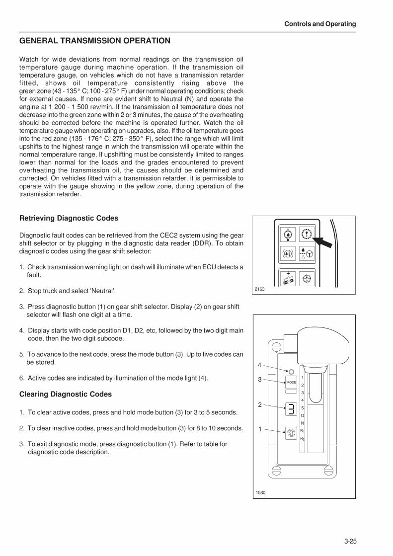
3-25
Controls and Operating
GENERAL TRANSMISSION OPERATION
Watch for wide deviations from normal readings on the transmission oil
temperature gauge during machine operation. If the transmission oil
temperature gauge, on vehicles which do not have a transmission retarder
fitted, shows oil temperature consistently rising above the
green zone (43 - 135° C; 100 - 275° F) under normal operating conditions; check
for external causes. If none are evident shift to Neutral (N) and operate the
engine at 1 200 - 1 500 rev/min. If the transmission oil temperature does not
decrease into the green zone within 2 or 3 minutes, the cause of the overheating
should be corrected before the machine is operated further. Watch the oil
temperature gauge when operating on upgrades, also. If the oil temperature goes
into the red zone (135 - 176° C; 275 - 350° F), select the range which will limit
upshifts to the highest range in which the transmission will operate within the
normal temperature range. If upshifting must be consistently limited to ranges
lower than normal for the loads and the grades encountered to prevent
overheating the transmission oil, the causes should be determined and
corrected. On vehicles fitted with a transmission retarder, it is permissible to
operate with the gauge showing in the yellow zone, during operation of the
transmission retarder.
Retrieving Diagnostic Codes
Diagnostic fault codes can be retrieved from the CEC2 system using the gear
shift selector or by plugging in the diagnostic data reader (DDR). To obtain
diagnostic codes using the gear shift selector:
1. Check transmission warning light on dash will illuminate when ECU detects a
fault.
2. Stop truck and select 'Neutral'.
3. Press diagnostic button (1) on gear shift selector. Display (2) on gear shift
selector will flash one digit at a time.
4. Display starts with code position D1, D2, etc, followed by the two digit main
code, then the two digit subcode.
5. To advance to the next code, press the mode button (3). Up to five codes can
be stored.
6. Active codes are indicated by illumination of the mode light (4).
Clearing Diagnostic Codes
1. To clear active codes, press and hold mode button (3) for 3 to 5 seconds.
2. To clear inactive codes, press and hold mode button (3) for 8 to 10 seconds.
3. To exit diagnostic mode, press diagnostic button (1). Refer to table for
diagnostic code description.
2163
3
4
2
1
1
2
3
4
5
D
N
R
MODE
1
R2
1580
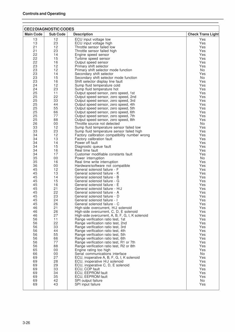
3-26
Controls and Operating
CEC2 DIAGNOSTIC CODES
Main Code Sub Code Description Check Trans Light
13 12 ECU input voltage low Yes13 23 ECU input voltage high Yes21 12 Throttle sensor failed low Yes21 23 Throttle sensor failed high Yes22 14 Engine speed sensor Yes22 15 Turbine speed sensor Yes22 16 Output speed sensor Yes23 12 Primary shift selector Yes23 12 Primary shift selector mode function No23 14 Secondary shift selector Yes23 15 Secondary shift selector mode function No23 16 Shift selector display line fault Yes24 12 Sump fluid temperature cold Yes24 23 Sump fluid temperature hot Yes25 11 Output speed sensor, zero speed, 1st Yes25 22 Output speed sensor, zero speed, 2nd Yes25 33 Output speed sensor, zero speed, 3rd Yes25 44 Output speed sensor, zero speed, 4th Yes25 55 Output speed sensor, zero speed, 5th Yes25 66 Output speed sensor, zero speed, 6th Yes25 77 Output speed sensor, zero speed, 7th Yes25 88 Output speed sensor, zero speed, 8th Yes26 00 Throttle source not detected No33 12 Sump fluid temperature sensor failed low Yes33 23 Sump fluid temperature sensor failed high Yes34 12 Factory calibration compatibility number wrong Yes34 13 Factory calibration fault Yes34 14 Power off fault Yes34 15 Diagnostic queue fault Yes34 16 Real time fault Yes34 17 Customer modifiable constants fault Yes35 00 Power interruption No35 16 Real time write interruption Yes36 00 Hardware/software not compatible Yes45 12 General solenoid failure - F Yes45 13 General solenoid failure - K Yes45 14 General solenoid failure - B Yes45 15 General solenoid failure - G Yes45 16 General solenoid failure - E Yes45 21 General solenoid failure - H/J Yes45 22 General solenoid failure - A Yes45 23 General solenoid failure - D Yes45 24 General solenoid failure - I Yes45 26 General solenoid failure - C Yes46 21 High-side overcurrent, H/J solenoid Yes46 26 High-side overcurrent, C, D, E solenoid Yes46 27 High-side overcurrent, A, B, F, G, I, K solenoid Yes56 11 Range verification ratio test, 1st Yes56 22 Range verification ratio test, 2nd Yes56 33 Range verification ratio test, 3rd Yes56 44 Range verification ratio test, 4th Yes56 55 Range verification ratio test, 5th Yes56 66 Range verification ratio test, 6th Yes56 77 Range verification ratio test, R1 or 7th Yes56 88 Range verification ratio test, R2 or 8th Yes65 00 Engine rating too high Yes66 00 Serial communications interface No69 27 ECU, inoperative A, B, F, G, I, K solenoid Yes69 28 ECU, inoperative H/J solenoid Yes69 29 ECU, inoperative C, D, E solenoid Yes69 33 ECU, COP fault Yes69 34 ECU, EEPROM fault Yes69 35 ECU, EEPROM fault Yes69 42 SPI output failure No69 43 SPI input failure Yes
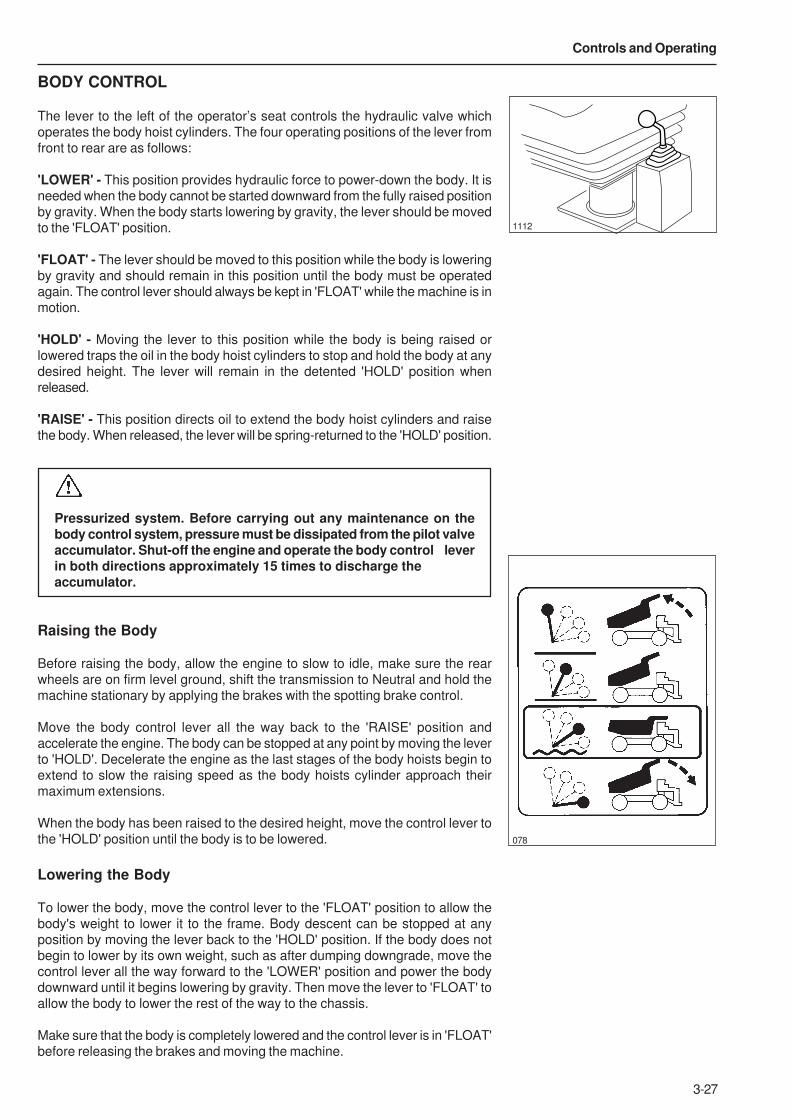
3-27
Controls and Operating
BODY CONTROL
The lever to the left of the operator’s seat controls the hydraulic valve which
operates the body hoist cylinders. The four operating positions of the lever from
front to rear are as follows:
'LOWER' - This position provides hydraulic force to power-down the body. It is
needed when the body cannot be started downward from the fully raised position
by gravity. When the body starts lowering by gravity, the lever should be moved
to the 'FLOAT' position.
'FLOAT' - The lever should be moved to this position while the body is lowering
by gravity and should remain in this position until the body must be operated
again. The control lever should always be kept in 'FLOAT' while the machine is in
motion.
'HOLD' - Moving the lever to this position while the body is being raised or
lowered traps the oil in the body hoist cylinders to stop and hold the body at any
desired height. The lever will remain in the detented 'HOLD' position when
released.
'RAISE' - This position directs oil to extend the body hoist cylinders and raise
the body. When released, the lever will be spring-returned to the 'HOLD' position.
Pressurized system. Before carrying out any maintenance on thebody control system, pressure must be dissipated from the pilot valveaccumulator. Shut-off the engine and operate the body control leverin both directions approximately 15 times to discharge theaccumulator.
Raising the Body
Before raising the body, allow the engine to slow to idle, make sure the rear
wheels are on firm level ground, shift the transmission to Neutral and hold the
machine stationary by applying the brakes with the spotting brake control.
Move the body control lever all the way back to the 'RAISE' position and
accelerate the engine. The body can be stopped at any point by moving the lever
to 'HOLD'. Decelerate the engine as the last stages of the body hoists begin to
extend to slow the raising speed as the body hoists cylinder approach their
maximum extensions.
When the body has been raised to the desired height, move the control lever to
the 'HOLD' position until the body is to be lowered.
Lowering the Body
To lower the body, move the control lever to the 'FLOAT' position to allow the
body's weight to lower it to the frame. Body descent can be stopped at any
position by moving the lever back to the 'HOLD' position. If the body does not
begin to lower by its own weight, such as after dumping downgrade, move the
control lever all the way forward to the 'LOWER' position and power the body
downward until it begins lowering by gravity. Then move the lever to 'FLOAT' to
allow the body to lower the rest of the way to the chassis.
Make sure that the body is completely lowered and the control lever is in 'FLOAT'
before releasing the brakes and moving the machine.
078
1112

3-28
Controls and Operating
This Page Intentionally Left Blank

4-1
4 - Operating the Truck

4-2
Operating the Truck
This Page Intentionally Left Blank
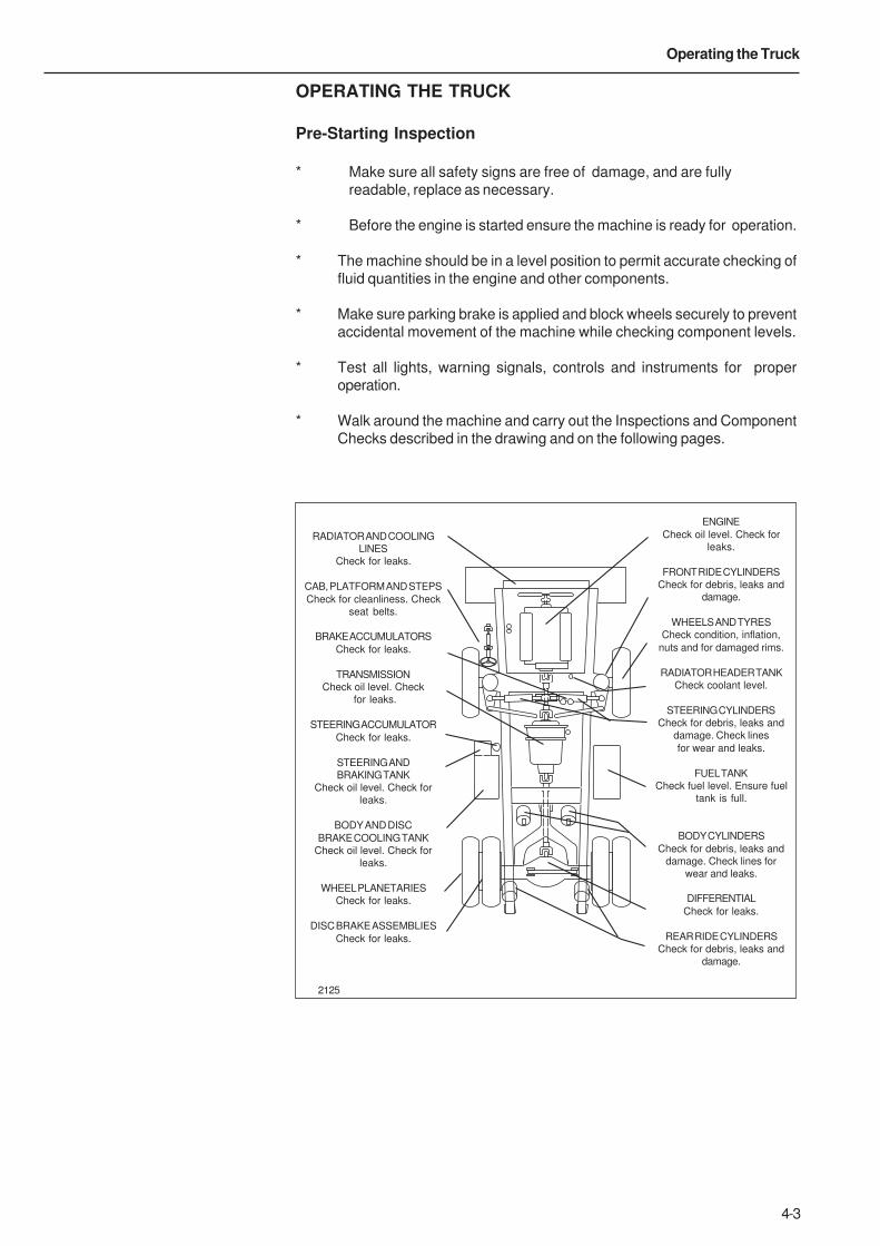
4-3
Operating the Truck
OPERATING THE TRUCK
Pre-Starting Inspection
* Make sure all safety signs are free of damage, and are fully
readable, replace as necessary.
* Before the engine is started ensure the machine is ready for operation.
* The machine should be in a level position to permit accurate checking of
fluid quantities in the engine and other components.
* Make sure parking brake is applied and block wheels securely to prevent
accidental movement of the machine while checking component levels.
* Test all lights, warning signals, controls and instruments for proper
operation.
* Walk around the machine and carry out the Inspections and Component
Checks described in the drawing and on the following pages.
2125
ENGINE
Check oil level. Check for
leaks.
FRONT RIDE CYLINDERS
Check for debris, leaks and
damage.
WHEELS AND TYRES
Check condition, inflation,
nuts and for damaged rims.
RADIATOR HEADER TANK
Check coolant level.
STEERING CYLINDERS
Check for debris, leaks and
damage. Check lines
for wear and leaks.
FUEL TANK
Check fuel level. Ensure fuel
tank is full.
BODY CYLINDERS
Check for debris, leaks and
damage. Check lines for
wear and leaks.
DIFFERENTIAL
Check for leaks.
REAR RIDE CYLINDERS
Check for debris, leaks and
damage.
RADIATOR AND COOLING
LINES
Check for leaks.
CAB, PLATFORM AND STEPS
Check for cleanliness. Check
seat belts.
BRAKE ACCUMULATORS
Check for leaks.
TRANSMISSION
Check oil level. Check
for leaks.
STEERING ACCUMULATOR
Check for leaks.
STEERING AND
BRAKING TANK
Check oil level. Check for
leaks.
BODY AND DISC
BRAKE COOLING TANK
Check oil level. Check for
leaks.
WHEEL PLANETARIES
Check for leaks.
DISC BRAKE ASSEMBLIES
Check for leaks.

4-4
Operating the Truck
COMPONENT CHECKS
1. Engine
With the engine off, check oil level. The oil level should be between the lower
and upper marks on the dipstick. Add oil if low.
2. Fuel Pre-filters
Drain sediment and water from fuel pre-filters until fuel runs clear.
3. Radiator Header Tank
Check coolant level. Add if low.
SCALDING HAZARD
Press button in centre of cap to bleed pressure before removing capcompletely. Fill to bottom of filler neck.
4. Air Cleaner Vacuator Valve(s)
Check for proper operation. Clean if required.
5. Tyres
Carefully inspect all tyres for cuts, bruises, or other damage and proper
inflation for the loads to be carried. Inflate all tyres to the recommended
pressure while cold.
037
640
2
259 1
041
038
3
4
5
NOTICE
In subfreezing temperatures,be sure that the coolant contains
sufficient antifreeze.
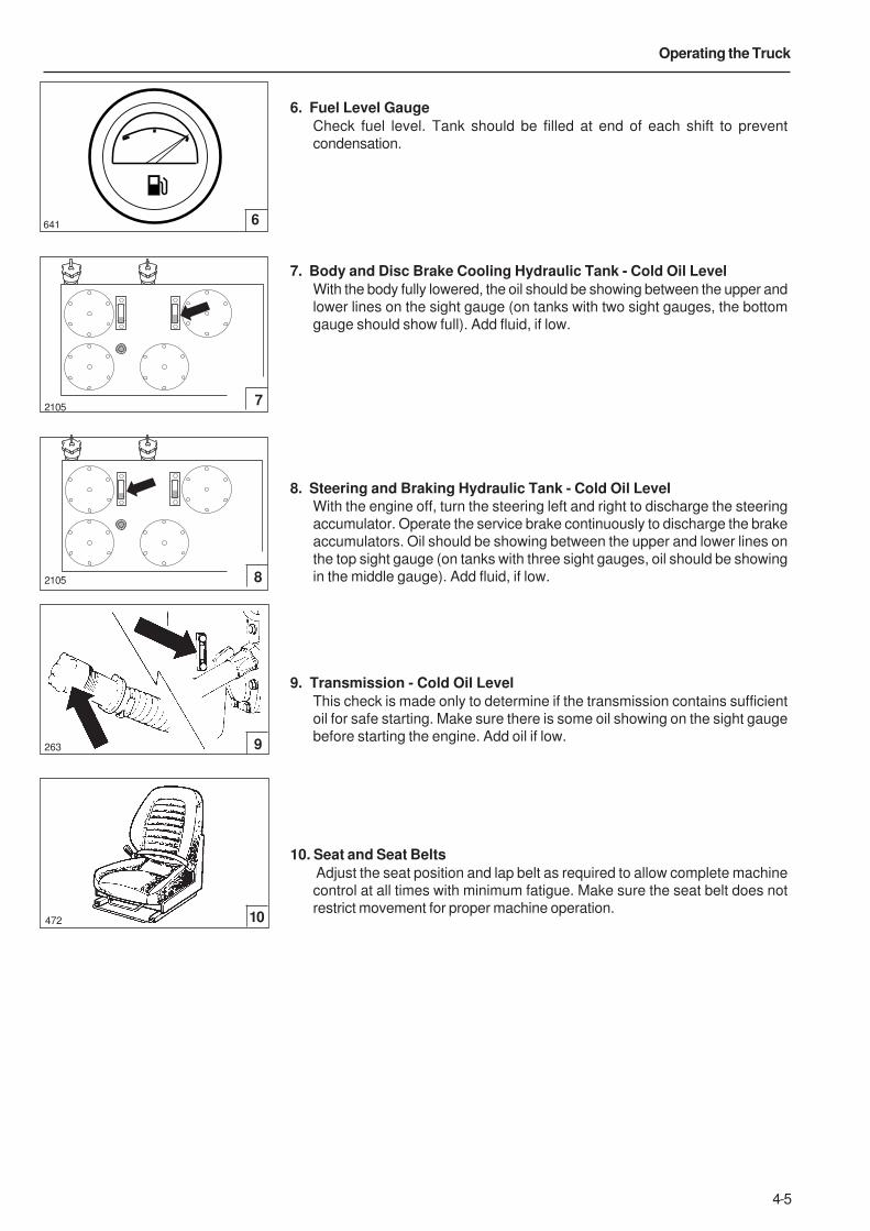
4-5
Operating the Truck
641 6
6. Fuel Level Gauge
Check fuel level. Tank should be filled at end of each shift to prevent
condensation.
7. Body and Disc Brake Cooling Hydraulic Tank - Cold Oil Level
With the body fully lowered, the oil should be showing between the upper and
lower lines on the sight gauge (on tanks with two sight gauges, the bottom
gauge should show full). Add fluid, if low.
8. Steering and Braking Hydraulic Tank - Cold Oil Level
With the engine off, turn the steering left and right to discharge the steering
accumulator. Operate the service brake continuously to discharge the brake
accumulators. Oil should be showing between the upper and lower lines on
the top sight gauge (on tanks with three sight gauges, oil should be showing
in the middle gauge). Add fluid, if low.
9. Transmission - Cold Oil Level
This check is made only to determine if the transmission contains sufficient
oil for safe starting. Make sure there is some oil showing on the sight gauge
before starting the engine. Add oil if low.
10. Seat and Seat Belts
Adjust the seat position and lap belt as required to allow complete machine
control at all times with minimum fatigue. Make sure the seat belt does not
restrict movement for proper machine operation.
7
8
2105
2105
10
9
472
263

4-6
Operating the Truck
SUSPENSION RIDE STRUTS
Suspension ride struts are oiled and charged with nitrogen to ensure optimum
ride comfort. However, ride struts may have been lowered during transportation
of the machine. These struts must be correctly set prior to operating the
machine.
The ride struts contain a mixture of nitrogen and oil, so when the struts are
lowered, some oil will be lost along with the nitrogen. Although only a small
amount of oil may be lost, this will still affect the final ride height, so it is
important that ride struts contain the correct volume of oil.
To recharge the ride struts, nitrogen pressures are given in the table below.
These pressures are dependant on oil levels being correct, refer to Section 180,
SUSPENSION SYSTEM in the Maintenance Manual. Use suitable lifting
equipment to fully extend ride struts and charge with nitrogen.
Note: The heights given are intended as reference only, cylinders should always
be set according to pressure. Refer to Section 180, SUSPENSION SYSTEM in
the Maintenance Manual for full details.
Note: It is advised to charge the ride struts by an additional 1.4 bar ( 20 lbf/in2) to
allow for pressure lost while carrying out pressure checks.
After recharging, the machine should be operated to allow ride struts to settle.
Then if ride heights are incorrect, the oil levels should be checked.
Truck TR35 TR40 TR45 TR60 TR70 TR100
Front Ride Struts - bar (lbf/in2) 11.7 (170) 13.8 (200) 13.8 (200) 13.8 (200) 17.2 (250) 16.3 (240)
Height - mm (in) 143 (5.6) 168 (6.6) 168 (6.6) 168 (6.6) 158 (6.2) 158 (6.2)
Rear Ride Struts - bar (lbf/in2) 5.5 (80) 7 (100) 7 (100) 8.3 (120) 8.3 (120) 8.3 (120)
Height - mm (in) 365 (14.4) 556 (21.9) 556 (21.9) 505 (19.9) 378 (14.9) 381 (15)
4-7
Operating the Truck
ENGINE OPERATION
NOTICE
Do not place engine under FULL LOAD at FULL SPEEDIMMEDIATELY after starting. ALWAYS allow the engine to fullycirculate lubricate and warm up gradually before operating at fullspeed and full load.
Operate engine at top rated speed when maximum power is neededfor the load. Operation of the engine below top rated speed canoccur during gear shifting due to the difference of ratios betweentransmission gears, but engine operation MUST NOT be sustainedmore than 30 seconds at full throttle below top rated speed.
NEVER idle the engine more than 5 minutes at a time; shut it off.
If any gauge operates outwith its normal operating range or awarning light illuminates, shut engine down immediately and re-port to service or maintenance personnel.
NOTICE
Never start the engine indoors unless proper exhaust ventilation isprovided to remove deadly exhaust gases. Once the engine isrunning, move the machine outdoors as soon as possible. Exhaustgases are hazardous and can cause unconsciousness and death.
Operating the engine beyond high idle speed can cause severeengine damage. The engine speed must not exceed 2 400 rev/minunder any circumstances. When descending a steep grade, use acombination of transmission gears, retarder and service brakes tocontrol the vehicle and engine speed.
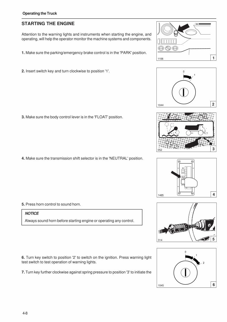
4-8
Operating the Truck
STARTING THE ENGINE
Attention to the warning lights and instruments when starting the engine, and
operating, will help the operator monitor the machine systems and components.
1. Make sure the parking/emergency brake control is in the 'PARK' position.
2. Insert switch key and turn clockwise to position '1'.
3. Make sure the body control lever is in the 'FLOAT' position.
4. Make sure the transmission shift selector is in the 'NEUTRAL' position.
5. Press horn control to sound horn.
NOTICE
Always sound horn before starting engine or operating any control.
6. Turn key switch to position '2' to switch on the ignition. Press warning light
test switch to test operation of warning lights.
7. Turn key further clockwise against spring pressure to position '3' to initiate the
0
1
3
1044
052
2
1106 1
0
1
2
314
1485
5
4
1045 6
N
R1
R2
D
1
2
3
4
5
MODE
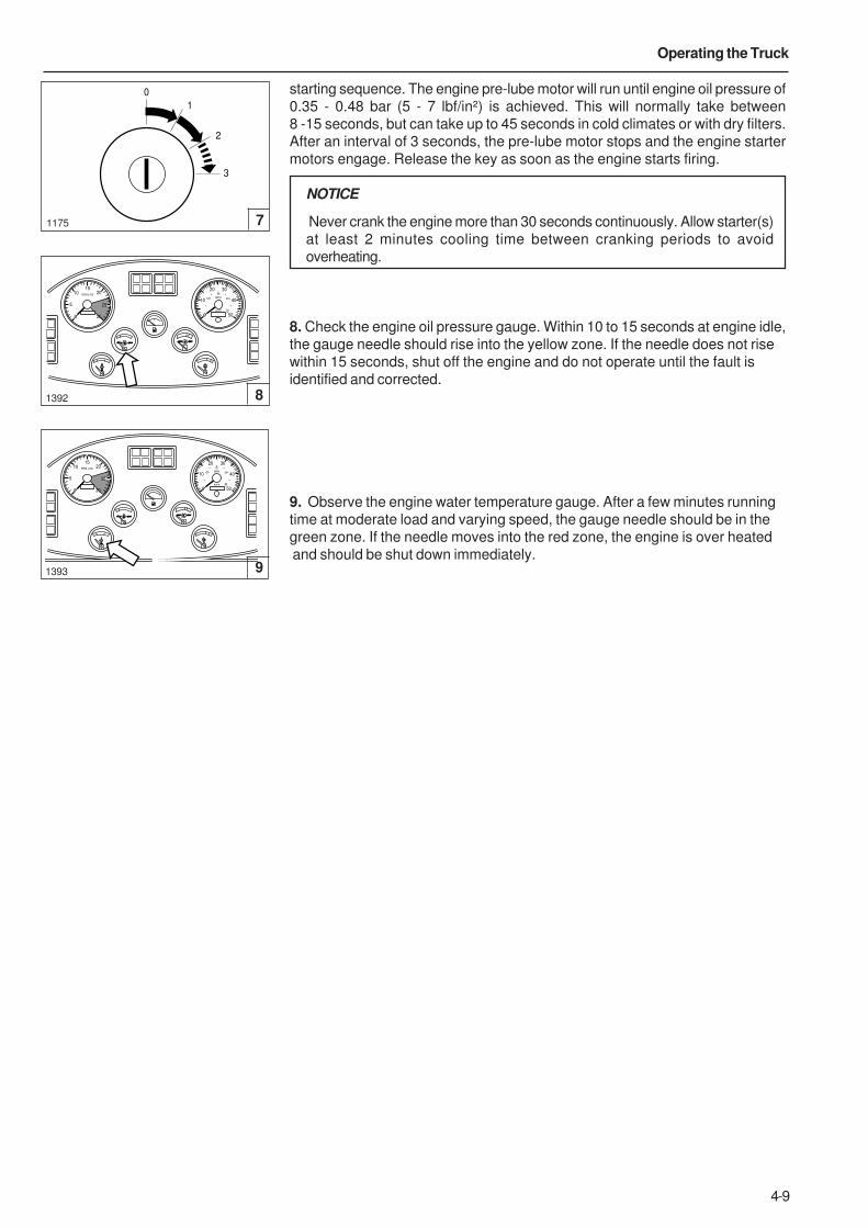
4-9
Operating the Truck
starting sequence. The engine pre-lube motor will run until engine oil pressure of
0.35 - 0.48 bar (5 - 7 lbf/in²) is achieved. This will normally take between
8 -15 seconds, but can take up to 45 seconds in cold climates or with dry filters.
After an interval of 3 seconds, the pre-lube motor stops and the engine starter
motors engage. Release the key as soon as the engine starts firing.
NOTICE
Never crank the engine more than 30 seconds continuously. Allow starter(s)
at least 2 minutes cooling time between cranking periods to avoid
overheating.
8. Check the engine oil pressure gauge. Within 10 to 15 seconds at engine idle,
the gauge needle should rise into the yellow zone. If the needle does not rise
within 15 seconds, shut off the engine and do not operate until the fault is
identified and corrected.
9. Observe the engine water temperature gauge. After a few minutes running
time at moderate load and varying speed, the gauge needle should be in the
green zone. If the needle moves into the red zone, the engine is over heated
and should be shut down immediately.
1392
0
1
2
3
1175 7
0
5
1015
20
25
RPM x100
30 0
10
3020
40
km/h
50
MPH20
20
20
20
8
0
5
1015
20
25
RPM x100
30 0
10
3020
40
km/h
50
MPH20
20
20
20
1393 9

4-10
Operating the Truck
STARTING THE ENGINE AT LOW AMBIENT
TEMPERATURES {Below 0 °C (32 °F)}
Follow steps 1 through 5 for 'Starting the engine' as described on page 4-8
then proceed as follows:
1. Fill starting aid reservoir if required. To fill, raise the cover of the reservoir
and push the filler can, head downwards, firmly over the filler valve of the
reservoir. Fill the transparent reservoir up to, but not over the 'MAXI' mark.
2. Turn key switch clockwise to position '2'. Press warning light test switch to
test operation of warning lights. Turn key further clockwise against spring
pressure to position '3' to crank the engine. When cranking has commenced,
operate the starting pilot pump. When the engine starts and runs, release
starter key and stop pumping. If necessary, further short applications can be
made in order to keep the engine running.
DO NOT use excessive starting fluid during starting or after the engine is
running.
3. Follow normal starting procedures but limit engine speed to 1 200 rev/min
and run for two to five minutes, depending on the temperature. Before moving,
operate the body control lever to raise and lower the body with no load. Turn
the steering wheel from lock to lock then straight ahead. These actions will
circulate warm oil throughout the hydraulic systems.
Starting fluid is poisonous and flammable. Breathing vapours orrepeated contact with skin can cause personal injury. Use only inwell ventilated areas. Use with care to avoid fires. Do not smoke whenchanging cylinders. Do not store cylinders in the operatorscompartment, living areas, in direct sunlight or at temperatures above490 C (1020 F). Discard cylinders properly. Do not puncture or burncylinders. Keep cylinders out of the reach of unauthorizedpersonnel.
STARTING THE ENGINE WITH JUMPER CABLES
Batteries contain sulfuric acid and can emit hydrogen gas. Checkfor required voltage and polarity connections to dischargedbatteries.
Excessive booster voltage and/or incorrect jumper cableconnections, open flames, lighted cigars, or other ignition sourcescan cause battery explosion/fire. Do not lean over batteries, andalways wear safety glasses, face shield, safety gloves, and anyother appropriate safety equipment when working with or nearbattery.
Do not jump start a vehicle by using arc welding equipment.Currents and voltages are dangerously high and cannot besufficiently reduced to make the method safe.
1
2
269
1035
0
1
2
3
START
PILOT
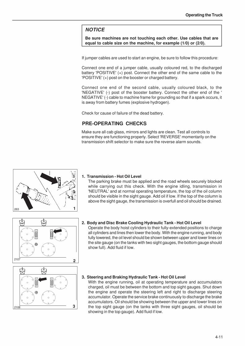
4-11
Operating the Truck
1. Transmission - Hot Oil LevelThe parking brake must be applied and the road wheels securely blocked
while carrying out this check. With the engine idling, transmission in
'NEUTRAL' and at normal operating temperature, the top of the oil column
should be visible in the sight gauge. Add oil if low. If the top of the column is
above the sight gauge, the transmission is overfull and oil should be drained.
2. Body and Disc Brake Cooling Hydraulic Tank - Hot Oil LevelOperate the body hoist cylinders to their fully-extended positions to charge
all cylinders and lines then lower the body. With the engine running, and body
fully lowered, the oil level should be shown between upper and lower lines on
the site gauge (on the tanks with two sight gauges, the bottom gauge should
show full). Add fluid if low.
3. Steering and Braking Hydraulic Tank - Hot Oil LevelWith the engine running, oil at operating temperature and accumulators
charged, oil must be between the bottom and top sight gauges. Shut down
the engine and operate the steering left and right to discharge steering
accumulator. Operate the service brake continuously to discharge the brake
accumulators. Oil should be showing between the upper and lower lines on
the top sight gauge (on the tanks with three sight gauges, oil should be
showing in the top gauge). Add fluid if low.
NOTICE
Be sure machines are not touching each other. Use cables that areequal to cable size on the machine, for example (1/0) or (2/0).
If jumper cables are used to start an engine, be sure to follow this procedure:
Connect one end of a jumper cable, usually coloured red, to the discharged
battery 'POSITIVE' (+) post. Connect the other end of the same cable to the
'POSITIVE' (+) post on the booster or charged battery.
Connect one end of the second cable, usually coloured black, to the
'NEGATIVE' (-) post of the booster battery. Connect the other end of the '
NEGATIVE' (-) cable to machine frame for grounding so that if a spark occurs, it
is away from battery fumes (explosive hydrogen).
Check for cause of failure of the dead battery.
PRE-OPERATING CHECKS
Make sure all cab glass, mirrors and lights are clean. Test all controls to
ensure they are functioning properly. Select 'REVERSE' momentarily on the
transmission shift selector to make sure the reverse alarm sounds.
2108
263
2107
1
2
3
4-12
Operating the Truck
BRAKE FUNCTION CHECKS
In addition to the above checks, the following brake function checks can be
carried out to determine if both the service and emergency brake systems are
functional before operating the machine.
Make sure the area around the machine is clear of personnel andobstructions before carrying out these checks.
If the machine moves during these checks, stop the machine, applythe parking brake and do not operate until the fault is corrected.
Note: The following checks are NOT intended to measure maximum brake
holding ability. If NEW brake pads are fitted, they MUST be burnished as per the
manufacturers recommendations before carrying out the checks.
Service Brake Holding Ability Check
Depress the service brake pedal and select 1st gear on the transmission shift
selector. Pull the parking/emergency brake control out to release the brakes.
Depress accelerator control and accelerate engine to 1350 rev/min. The
machine should not move. Decelerate engine, shift transmission to 'NEUTRAL'
and apply the parking brake control switch before releasing the service brake.
Emergency Brake Holding Ability Check
Depress the service brake pedal, release the parking/emergency brakes, select
first gear, apply the park/emergency brakes and release the service brake pedal.
Depress accelerator control and accelerate engine to 1350 rev/min. The
machine should not move. Decelerate engine and shift transmission to
'NEUTRAL'.
Note: Brake holding effort required to hold a machine static at a specific engine
speed, can vary from machine to machine due to differences in engine
performance, powertrain efficiency, etc., as well as differences in brake holding
ability.
Note: As an indication of system deterioration, the engine speed at which point
the machine moved, with the service or emergency brakes applied, can be
compared against the engine speed your machine was able to hold to on a
previous check.
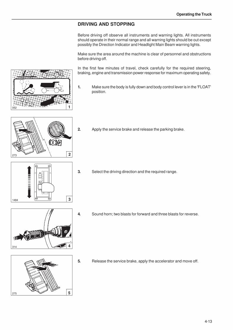
4-13
Operating the Truck
DRIVING AND STOPPING
Before driving off observe all instruments and warning lights. All instruments
should operate in their normal range and all warning lights should be out except
possibly the Direction Indicator and Headlight Main Beam warning lights.
Make sure the area around the machine is clear of personnel and obstructions
before driving off.
In the first few minutes of travel, check carefully for the required steering,
braking, engine and transmission power response for maximum operating safety.
1. Make sure the body is fully down and body control lever is in the 'FLOAT'
position.
2. Apply the service brake and release the parking brake.
3. Select the driving direction and the required range.
4. Sound horn; two blasts for forward and three blasts for reverse.
5. Release the service brake, apply the accelerator and move off.
1484 3
052
273
1
2
4314
5275
N
R1
R2
D
1
2
3
4
5
MODE
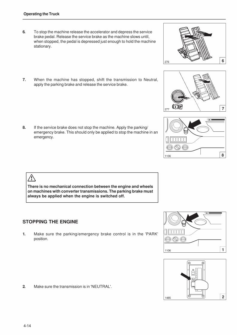
4-14
Operating the Truck
6. To stop the machine release the accelerator and depress the service
brake pedal. Release the service brake as the machine slows until,
when stopped, the pedal is depressed just enough to hold the machine
stationary.
7. When the machine has stopped, shift the transmission to Neutral,
apply the parking brake and release the service brake.
8. If the service brake does not stop the machine. Apply the parking/
emergency brake. This should only be applied to stop the machine in an
emergency.
There is no mechanical connection between the engine and wheelson machines with converter transmissions. The parking brake mustalways be applied when the engine is switched off.
STOPPING THE ENGINE
1. Make sure the parking/emergency brake control is in the 'PARK'
position.
2. Make sure the transmission is in 'NEUTRAL'.
6276
277 7
81106
1485 2
1106 1
N
R1
R2
D
1
2
3
4
5
MODE
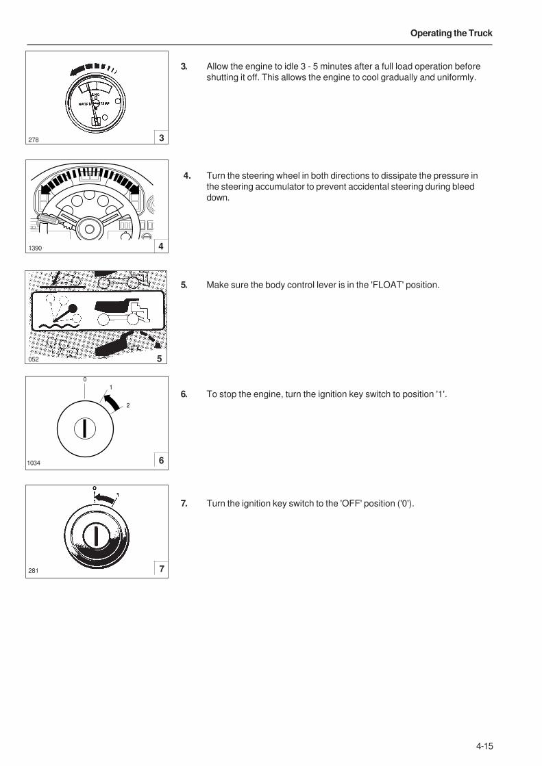
4-15
Operating the Truck
3. Allow the engine to idle 3 - 5 minutes after a full load operation before
shutting it off. This allows the engine to cool gradually and uniformly.
4. Turn the steering wheel in both directions to dissipate the pressure in
the steering accumulator to prevent accidental steering during bleed
down.
5. Make sure the body control lever is in the 'FLOAT' position.
6. To stop the engine, turn the ignition key switch to position '1'.
7. Turn the ignition key switch to the 'OFF' position ('0').
278 3
1390 4
052
6
281 7
0
1
2
1034
5
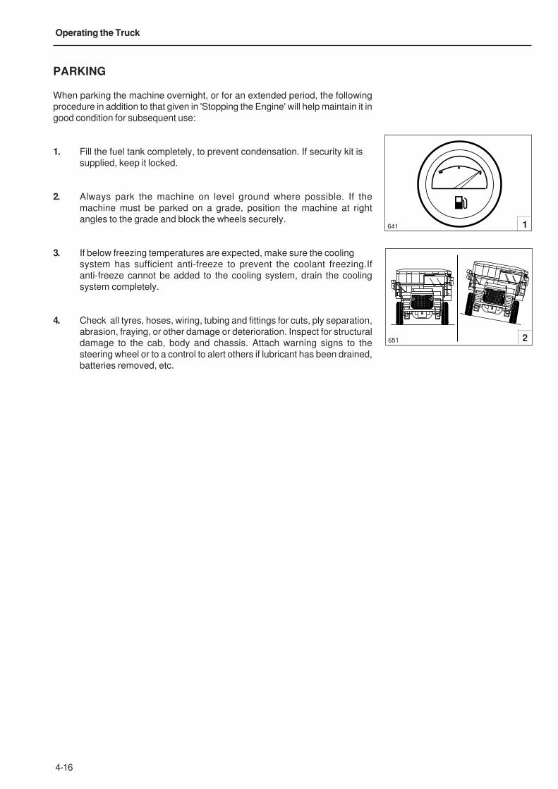
4-16
Operating the Truck
PARKING
When parking the machine overnight, or for an extended period, the following
procedure in addition to that given in 'Stopping the Engine' will help maintain it in
good condition for subsequent use:
1. Fill the fuel tank completely, to prevent condensation. If security kit is
supplied, keep it locked.
2. Always park the machine on level ground where possible. If the
machine must be parked on a grade, position the machine at right
angles to the grade and block the wheels securely.
3. If below freezing temperatures are expected, make sure the cooling
system has sufficient anti-freeze to prevent the coolant freezing.If
anti-freeze cannot be added to the cooling system, drain the cooling
system completely.
4. Check all tyres, hoses, wiring, tubing and fittings for cuts, ply separation,
abrasion, fraying, or other damage or deterioration. Inspect for structural
damage to the cab, body and chassis. Attach warning signs to the
steering wheel or to a control to alert others if lubricant has been drained,
batteries removed, etc.
651
641
2
1

5-1
5 - Working the Truck

5-2
Working the Truck
This Page Intentionally Left Blank
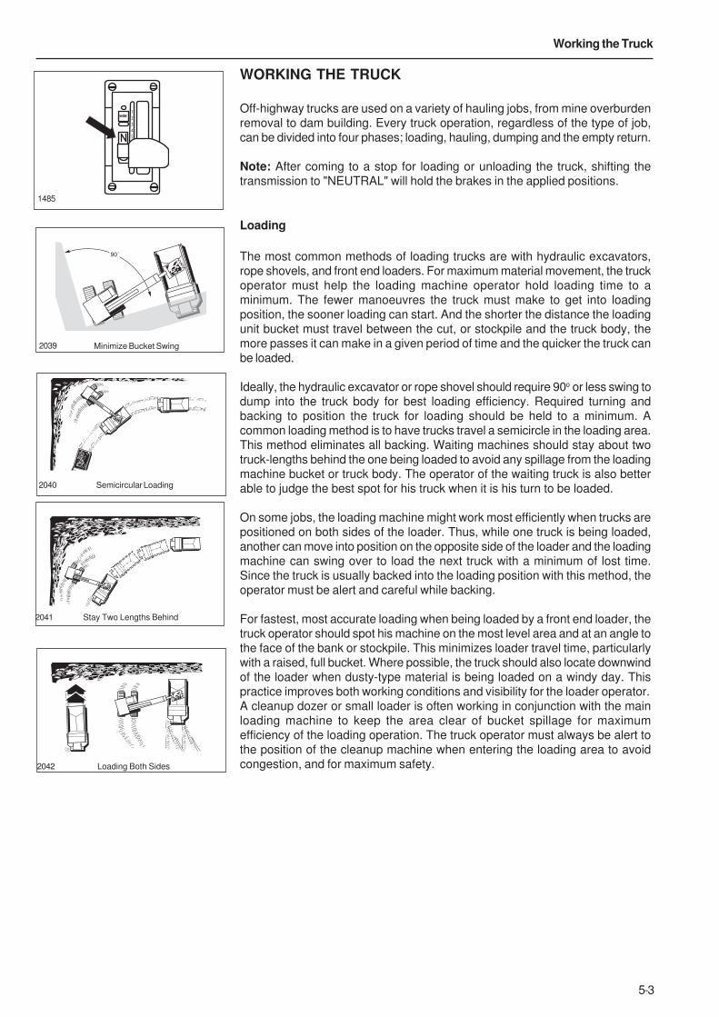
5-3
Working the Truck
WORKING THE TRUCK
Off-highway trucks are used on a variety of hauling jobs, from mine overburden
removal to dam building. Every truck operation, regardless of the type of job,
can be divided into four phases; loading, hauling, dumping and the empty return.
Note: After coming to a stop for loading or unloading the truck, shifting the
transmission to "NEUTRAL" will hold the brakes in the applied positions.
Loading
The most common methods of loading trucks are with hydraulic excavators,
rope shovels, and front end loaders. For maximum material movement, the truck
operator must help the loading machine operator hold loading time to a
minimum. The fewer manoeuvres the truck must make to get into loading
position, the sooner loading can start. And the shorter the distance the loading
unit bucket must travel between the cut, or stockpile and the truck body, the
more passes it can make in a given period of time and the quicker the truck can
be loaded.
Ideally, the hydraulic excavator or rope shovel should require 90o or less swing to
dump into the truck body for best loading efficiency. Required turning and
backing to position the truck for loading should be held to a minimum. A
common loading method is to have trucks travel a semicircle in the loading area.
This method eliminates all backing. Waiting machines should stay about two
truck-lengths behind the one being loaded to avoid any spillage from the loading
machine bucket or truck body. The operator of the waiting truck is also better
able to judge the best spot for his truck when it is his turn to be loaded.
On some jobs, the loading machine might work most efficiently when trucks are
positioned on both sides of the loader. Thus, while one truck is being loaded,
another can move into position on the opposite side of the loader and the loading
machine can swing over to load the next truck with a minimum of lost time.
Since the truck is usually backed into the loading position with this method, the
operator must be alert and careful while backing.
For fastest, most accurate loading when being loaded by a front end loader, the
truck operator should spot his machine on the most level area and at an angle to
the face of the bank or stockpile. This minimizes loader travel time, particularly
with a raised, full bucket. Where possible, the truck should also locate downwind
of the loader when dusty-type material is being loaded on a windy day. This
practice improves both working conditions and visibility for the loader operator.
A cleanup dozer or small loader is often working in conjunction with the main
loading machine to keep the area clear of bucket spillage for maximum
efficiency of the loading operation. The truck operator must always be alert to
the position of the cleanup machine when entering the loading area to avoid
congestion, and for maximum safety.
1485
Semicircular Loading2040
2041 Stay Two Lengths Behind
Loading Both Sides2042
Minimize Bucket Swing2039
90˚
MODE
1
2
3
4
5

5-4
Working the Truck
The following precautions should be observed when approaching the loading
area and while being loaded -
Avoid rocks and other shovel spillage that can needlessly damagetyres or other truck components. Allow the cleanup machine sufficienttime to clear up such debris.
Do not move the truck into loading position with the shovel bucketswinging overhead. Large rocks that might fall from the bucket can bedangerous to both the truck and operator.
Keep your head and arms inside the cab during loading to avoid thedanger of falling rocks or other shovel spillage.
When the loader operator signals that the truck is loaded, sound two blasts on
the horn, release the brakes and shift the transmission to drive (D). Move out of
the loading area and onto the haul road with the least possible delay to allow any
waiting truck to move into the loading position as soon as possible.
Watch Other Trucks2043
Load Downwind
Watch Cleanup Machine
2044
2045
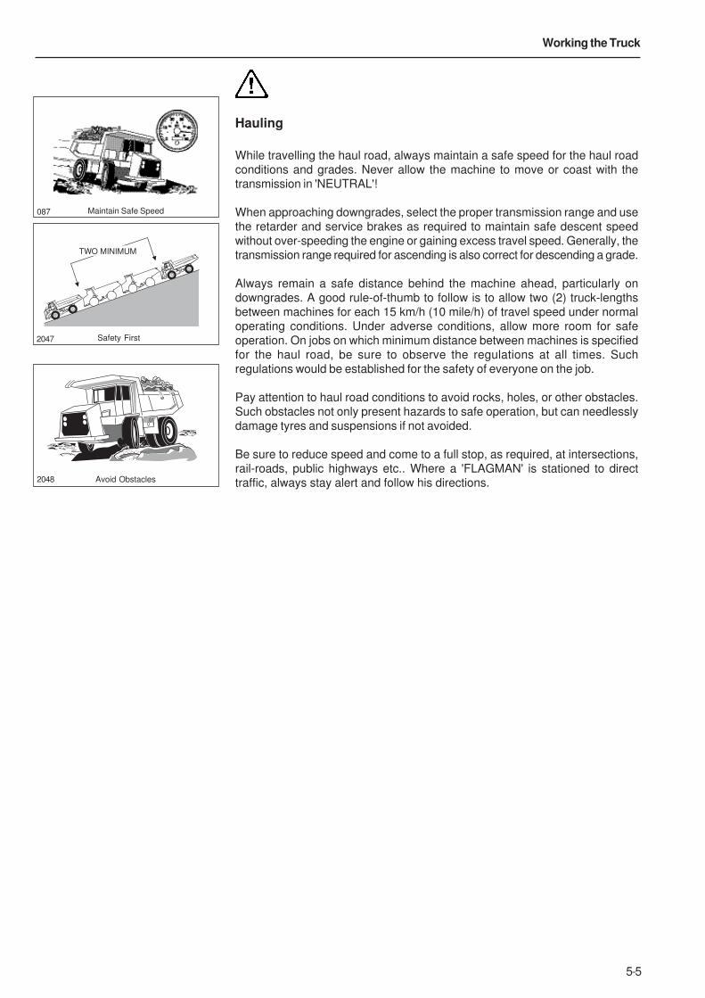
5-5
Working the Truck
Hauling
While travelling the haul road, always maintain a safe speed for the haul road
conditions and grades. Never allow the machine to move or coast with the
transmission in 'NEUTRAL'!
When approaching downgrades, select the proper transmission range and use
the retarder and service brakes as required to maintain safe descent speed
without over-speeding the engine or gaining excess travel speed. Generally, the
transmission range required for ascending is also correct for descending a grade.
Always remain a safe distance behind the machine ahead, particularly on
downgrades. A good rule-of-thumb to follow is to allow two (2) truck-lengths
between machines for each 15 km/h (10 mile/h) of travel speed under normal
operating conditions. Under adverse conditions, allow more room for safe
operation. On jobs on which minimum distance between machines is specified
for the haul road, be sure to observe the regulations at all times. Such
regulations would be established for the safety of everyone on the job.
Pay attention to haul road conditions to avoid rocks, holes, or other obstacles.
Such obstacles not only present hazards to safe operation, but can needlessly
damage tyres and suspensions if not avoided.
Be sure to reduce speed and come to a full stop, as required, at intersections,
rail-roads, public highways etc.. Where a 'FLAGMAN' is stationed to direct
traffic, always stay alert and follow his directions.
Maintain Safe Speed087
2047
TWO MINIMUM
Safety First
Avoid Obstacles2048
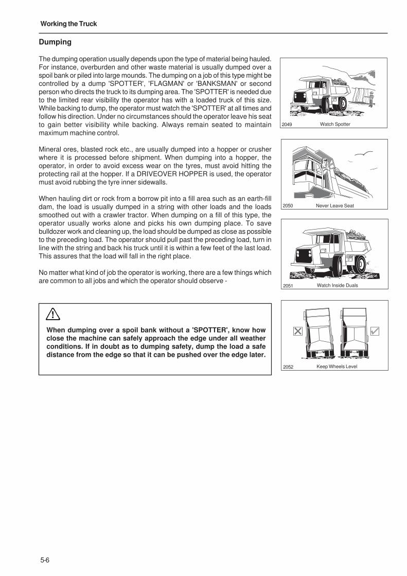
5-6
Working the Truck
Dumping
The dumping operation usually depends upon the type of material being hauled.
For instance, overburden and other waste material is usually dumped over a
spoil bank or piled into large mounds. The dumping on a job of this type might be
controlled by a dump 'SPOTTER', 'FLAGMAN' or 'BANKSMAN' or second
person who directs the truck to its dumping area. The 'SPOTTER' is needed due
to the limited rear visibility the operator has with a loaded truck of this size.
While backing to dump, the operator must watch the 'SPOTTER' at all times and
follow his direction. Under no circumstances should the operator leave his seat
to gain better visibility while backing. Always remain seated to maintain
maximum machine control.
Mineral ores, blasted rock etc., are usually dumped into a hopper or crusher
where it is processed before shipment. When dumping into a hopper, the
operator, in order to avoid excess wear on the tyres, must avoid hitting the
protecting rail at the hopper. If a DRIVEOVER HOPPER is used, the operator
must avoid rubbing the tyre inner sidewalls.
When hauling dirt or rock from a borrow pit into a fill area such as an earth-fill
dam, the load is usually dumped in a string with other loads and the loads
smoothed out with a crawler tractor. When dumping on a fill of this type, the
operator usually works alone and picks his own dumping place. To save
bulldozer work and cleaning up, the load should be dumped as close as possible
to the preceding load. The operator should pull past the preceding load, turn in
line with the string and back his truck until it is within a few feet of the last load.
This assures that the load will fall in the right place.
No matter what kind of job the operator is working, there are a few things which
are common to all jobs and which the operator should observe -
When dumping over a spoil bank without a 'SPOTTER', know howclose the machine can safely approach the edge under all weatherconditions. If in doubt as to dumping safety, dump the load a safedistance from the edge so that it can be pushed over the edge later.
Watch Spotter2049
Never Leave Seat2050
Watch Inside Duals2051
Keep Wheels Level2052
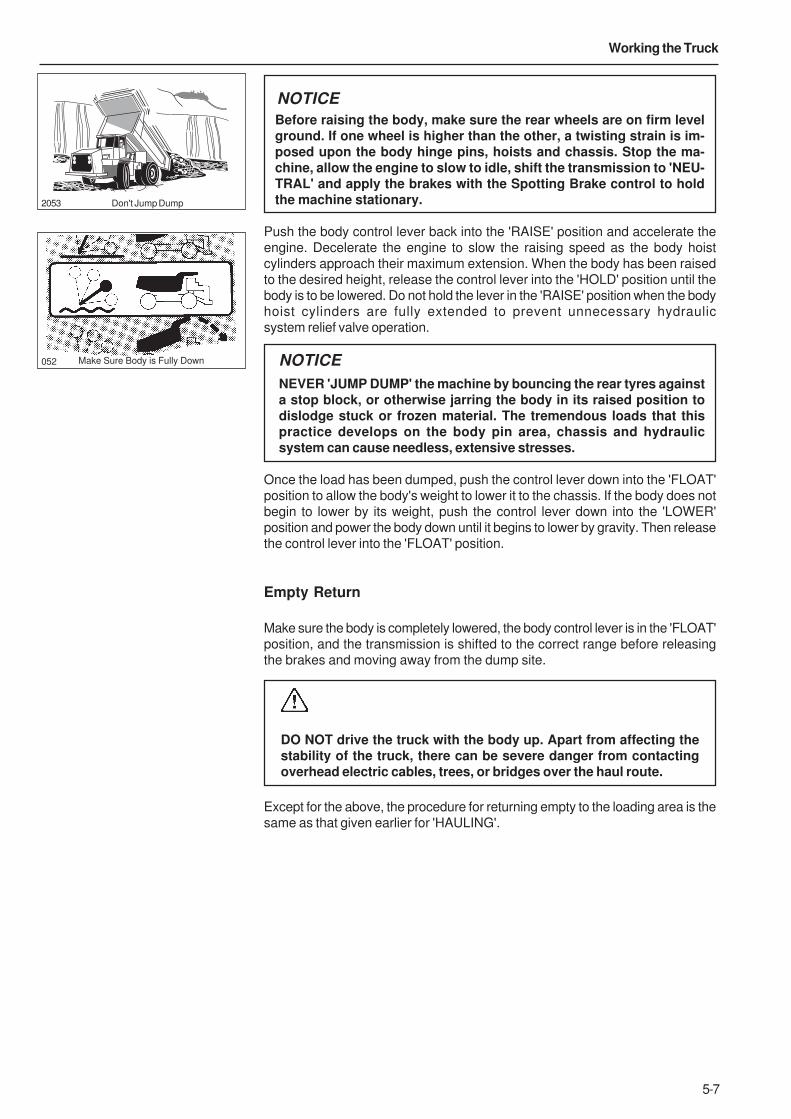
5-7
Working the Truck
Before raising the body, make sure the rear wheels are on firm levelground. If one wheel is higher than the other, a twisting strain is im-posed upon the body hinge pins, hoists and chassis. Stop the ma-chine, allow the engine to slow to idle, shift the transmission to 'NEU-TRAL' and apply the brakes with the Spotting Brake control to holdthe machine stationary.
Push the body control lever back into the 'RAISE' position and accelerate the
engine. Decelerate the engine to slow the raising speed as the body hoist
cylinders approach their maximum extension. When the body has been raised
to the desired height, release the control lever into the 'HOLD' position until the
body is to be lowered. Do not hold the lever in the 'RAISE' position when the body
hoist cylinders are fully extended to prevent unnecessary hydraulic
system relief valve operation.
NOTICE
NEVER 'JUMP DUMP' the machine by bouncing the rear tyres againsta stop block, or otherwise jarring the body in its raised position todislodge stuck or frozen material. The tremendous loads that thispractice develops on the body pin area, chassis and hydraulicsystem can cause needless, extensive stresses.
Once the load has been dumped, push the control lever down into the 'FLOAT'
position to allow the body's weight to lower it to the chassis. If the body does not
begin to lower by its weight, push the control lever down into the 'LOWER'
position and power the body down until it begins to lower by gravity. Then release
the control lever into the 'FLOAT' position.
Empty Return
Make sure the body is completely lowered, the body control lever is in the 'FLOAT'
position, and the transmission is shifted to the correct range before releasing
the brakes and moving away from the dump site.
DO NOT drive the truck with the body up. Apart from affecting thestability of the truck, there can be severe danger from contactingoverhead electric cables, trees, or bridges over the haul route.
Except for the above, the procedure for returning empty to the loading area is the
same as that given earlier for 'HAULING'.
Make Sure Body is Fully Down052
Don't Jump Dump2053
NOTICE

5-8
Working the Truck
This Page Intentionally Left Blank

6-1
6 - Roading

6-2
Roading
This Page Intentionally Left Blank

6-3
Roading
ROADING
These machines are equipped with cylinders containing compressednitrogen gas. Transportation of these machines by any method mayrequire a special permit from the appropriate authority of the coun-try involved. Consult your Dealer for details.
General'ROADING' (operating a truck over public highways) requires special care and
attention. Trucks, because of their large size, are slower and less manoeuvrable
than most other vehicles encountered on the road. Yet, while on the road, they
must be operated for extended periods of time at or near maximum speeds.
Before 'ROADING' a truck for an extended distance between jobs, or between
widely scattered sections of a job, the machine must be properly equipped and
in good condition. It is also recommended to carry a 'Warning Triangle'.
The operator must use extra care while on the public highways and remain
constantly alert, especially for overhead cables and low bridges.
Necessary permits must be obtained from the proper authorities before the
machine is 'ROADED' on public highways.
PREPARATION PRIOR TO ROADING
Lubrication
Thoroughly lubricate and service all components and systems as described
under 'LUBRICATION AND SERVICING' in this handbook and/or Maintenance
Manual for this machine.
InspectionPerform all pre-starting and post-starting checks described in this Handbook.
Pay particular attention to the function of all instruments and lights, and make
any repairs necessary.
NOTICE
Improper tyre inflation during over-the-road operation can cause rapidtyre deterioration by overheating. Tyre pressures increase with heat.Always check pressures while tyre is cold. Consult your tyre dealerfor proper pressures and tyre speed limits for roading.
Check the inflation pressures of all tyres, while cold, with an accurate tyre
pressure gauge. Inflate tyres if necessary, while cold, to the recommended
pressure for 'ROADING'. Inspect all tyres thoroughly and carefully for stones or
other debris embedded in the treads or carcasses. Inspect for cuts, bruises,
burned beads, abnormal wear and damaged wheels rims. Replace any damaged
or excessively worn tyres.
Check all hoses, drain cocks, fuel level check cocks, and other potential sources
of leaks. Make sure that all leaks are repaired and that all drain cocks are
sufficiently tightened to avoid subsequent loosening. Make sure that all warning
flags, oversize load signs, etc. are in place and secure.
6-4
Roading
Clean all glass and adjust the seat for proper operation of all controls.
Check all lights and other controls for proper operation.
Make sure the truck body is empty, fully lowered and the body control lever is in
the 'FLOAT' position.
Note: Make sure the body control lever is in the 'FLOAT' position. Failure to
comply to this caution could result in overheating the hydraulic oil and failure of
the hydraulic system components.
In Case of TroubleIf trouble develops en route, move machine off the road at the first safe parking
place, and shut off the engine. Carefully note as many of the symptoms of the
trouble as possible, such as rough engine operation with loss of power and
overheating, or, loss of speed and transmission clutch pressure with normal
engine operation etc..
If the area in which the trouble occurs requires that the machine be left
unattended while the trouble is reported by phone, disconnect a battery cable
and apply security locks, if so equipped, before leaving the parked machine.
Make sure body is completely lowered and the parking brake is applied.
Report the following data as soon as possible.
1. Exact location.
2. Destination.
3. The nature of the trouble (with as many details as possible) and the time
and conditions under which it happened.
4. The telephone number at which the machine operator can be reached.
NOTICE
Do not attempt to restart or operate the machine unless instructed todo so. An engine, pump, transmission or other component that devel-ops a minor defect can be completely destroyed in just a few extraminutes of unnecessary operation.

7-1
7 - Moving a Disabled Truck

7-2
Moving a Disabled Truck
This Page Intentionally Left Blank
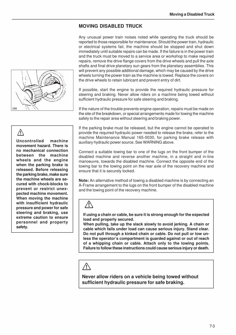
7-3
Moving a Disabled Truck
MOVING DISABLED TRUCK
Any unusual power train noises noted while operating the truck should be
reported to those responsible for maintenance. Should the power train, hydraulic
or electrical systems fail, the machine should be stopped and shut down
immediately until suitable repairs can be made. If the failure is in the power train
and the truck must be moved to a service area or workshop to make required
repairs, remove the drive flange covers from the drive wheels and pull the axle
shafts and final drive planetary sun gears from the planetary assemblies. This
will prevent any possible additional damage, which may be caused by the drive
wheels turning the power train as the machine is towed. Replace the covers on
the drive wheels to retain lubricant and prevent entry of dirt.
If possible, start the engine to provide the required hydraulic pressure for
steering and braking. Never allow riders on a machine being towed without
sufficient hydraulic pressure for safe steering and braking.
If the nature of the trouble prevents engine operation, repairs must be made on
the site of the breakdown, or special arrangements made for towing the machine
safely to the repair area without steering and braking power.
If the parking brake must be released, but the engine cannot be operated to
provide the required hydraulic power needed to release the brake, refer to the
machine Maintenance Manual 165-0030, for parking brake release with
auxiliary hydraulic power source. See WARNING above.
Connect a suitable towing bar to one of the lugs on the front bumper of the
disabled machine and reverse another machine, in a straight and in-line
manoeuvre, towards the disabled machine. Connect the opposite end of the
towing bar to the towing point on the rear axle of the recovery machine and
ensure that it is securely locked.
Note: An alternative method of towing a disabled machine is by connecting an
A-Frame arrangement to the lugs on the front bumper of the disabled machine
and the towing point of the recovery machine.
098
Uncontrolled machinemovement hazard. There isno mechanical connectionbetween the machinewheels and the enginewhen the parking brake isreleased. Before releasingthe parking brake, make surethe machine wheels are se-cured with chock-blocks toprevent or restrict unex-pected machine movement.When moving the machinewith insufficient hydraulicpressure and power for safesteering and braking, useextreme caution to ensurepersonnel and propertysafety.
If using a chain or cable, be sure it is strong enough for the expectedload and properly secured.When pulling, take up the slack slowly to avoid jerking. A chain orcable which fails under load can cause serious injury. Stand clear.Do not pull through a kinked chain or cable. Do not pull or tow un-less the operator’s compartment is guarded against or out of reachof a whipping chain or cable. Attach only to the towing points.Failure to follow these instructions could cause serious injury or death.
Never allow riders on a vehicle being towed withoutsufficient hydraulic pressure for safe braking.

7-4
Moving a Disabled Truck
This Page Intentionally Left Blank
8-1
8 - Lubrication and Servicing

8-2
Lubrication and Servicing
This Page Intentionally Left Blank
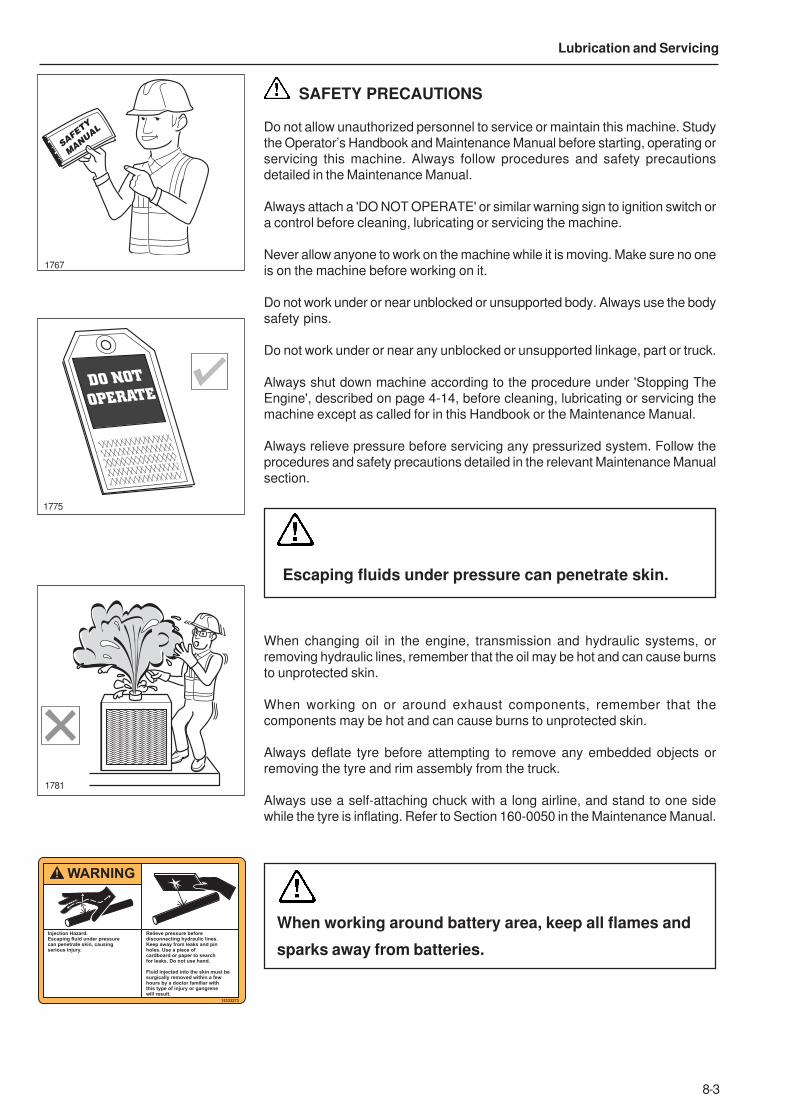
8-3
Lubrication and Servicing
SAFETY PRECAUTIONS
Do not allow unauthorized personnel to service or maintain this machine. Studythe Operator’s Handbook and Maintenance Manual before starting, operating orservicing this machine. Always follow procedures and safety precautionsdetailed in the Maintenance Manual.
Always attach a 'DO NOT OPERATE' or similar warning sign to ignition switch ora control before cleaning, lubricating or servicing the machine.
Never allow anyone to work on the machine while it is moving. Make sure no oneis on the machine before working on it.
Do not work under or near unblocked or unsupported body. Always use the bodysafety pins.
Do not work under or near any unblocked or unsupported linkage, part or truck.
Always shut down machine according to the procedure under 'Stopping TheEngine', described on page 4-14, before cleaning, lubricating or servicing themachine except as called for in this Handbook or the Maintenance Manual.
Always relieve pressure before servicing any pressurized system. Follow theprocedures and safety precautions detailed in the relevant Maintenance Manualsection.
Escaping fluids under pressure can penetrate skin.
When changing oil in the engine, transmission and hydraulic systems, orremoving hydraulic lines, remember that the oil may be hot and can cause burnsto unprotected skin.
When working on or around exhaust components, remember that thecomponents may be hot and can cause burns to unprotected skin.
Always deflate tyre before attempting to remove any embedded objects orremoving the tyre and rim assembly from the truck.
Always use a self-attaching chuck with a long airline, and stand to one sidewhile the tyre is inflating. Refer to Section 160-0050 in the Maintenance Manual.
SAFETY
MANUAL
1767
DO NOT
OPERATE
1775
1781
15333273
Injection Hazard.Escaping fluid under pressurecan penetrate skin, causingserious injury.
Relieve pressure beforedisconnecting hydraulic lines.Keep away from leaks and pinholes. Use a piece of cardboard or paper to searchfor leaks. Do not use hand.
Fluid injected into the skin must besurgically removed within a fewhours by a doctor familiar with this type of injury or gangrenewill result.
WARNING
When working around battery area, keep all flames and
sparks away from batteries.

8-4
Lubrication and Servicing
LUBRICATION AND SERVICING
These trucks are fitted with engine andtransmission oil pans which permitoperation at maximum gradeability asdesignated in the ‘Performance Data’ sectionof the relevant Sales Specification Sheet.
Lubrication is an essential part of preventivemaintenance. It is important that the instructionsregarding types of lubricants and the frequency oftheir application be followed to prolong the useful lifeof the machine. Periodic lubrication of moving partsreduces to a minimum the possibility of mechanicalfailures.
All change and service periods are recommendationsbased on average operating conditions. Lubricantsshowing evidence of excessive heat, oxidation or dirtshould be changed more frequently to prevent theseconditions.
Lubricant change and service periods must beestablished on the basis of individual job conditions,utilizing oil sampling and recommendations fromlubricant suppliers.
Thoroughly clean all fittings, caps, plugs, etc., toprevent dirt from entering any system while carryingout servicing procedures. Lubricants must be atoperating temperature when draining.
Note: Do not operate any system unless the oil levelis within the recommended operating levels asindicated on oil level dipstick, sight gauge or levelplug.
Small circles on the following illustration representpoints at which lubrication or servicing must takeplace, at the intervals indicated on the left-hand sideof the lubrication chart. The numbers on theillustration contain reference numbers which is givenin the ‘Ref. Points’ column of the Lubrication andService chart.
TRANSMISSION FLUID - Transynd RD
For non TranSynd RD filled transmissions refer to theservice schedule detailed from page 8-5 onwards.
Note: For units filled with TranSynd RD, the serviceschedule for the transmission differs from thosewhich are filled with EO. The use of any other oil in
units which are TranSynd RD filled may result in damage tothe transmission.
Trucks filled with Allison TranSynd RD oil shouldonly be filled with TranSynd RD oil at drain andrefill intervals. Use of other oils or mixing of oilsis prohibited and may cause damage to thetransmission. If there is any uncertainty consultthe manufacturer.
For TranSynd RD filled transmissions, refer to page 8-7 forservice intervals and recommended lubricant details.
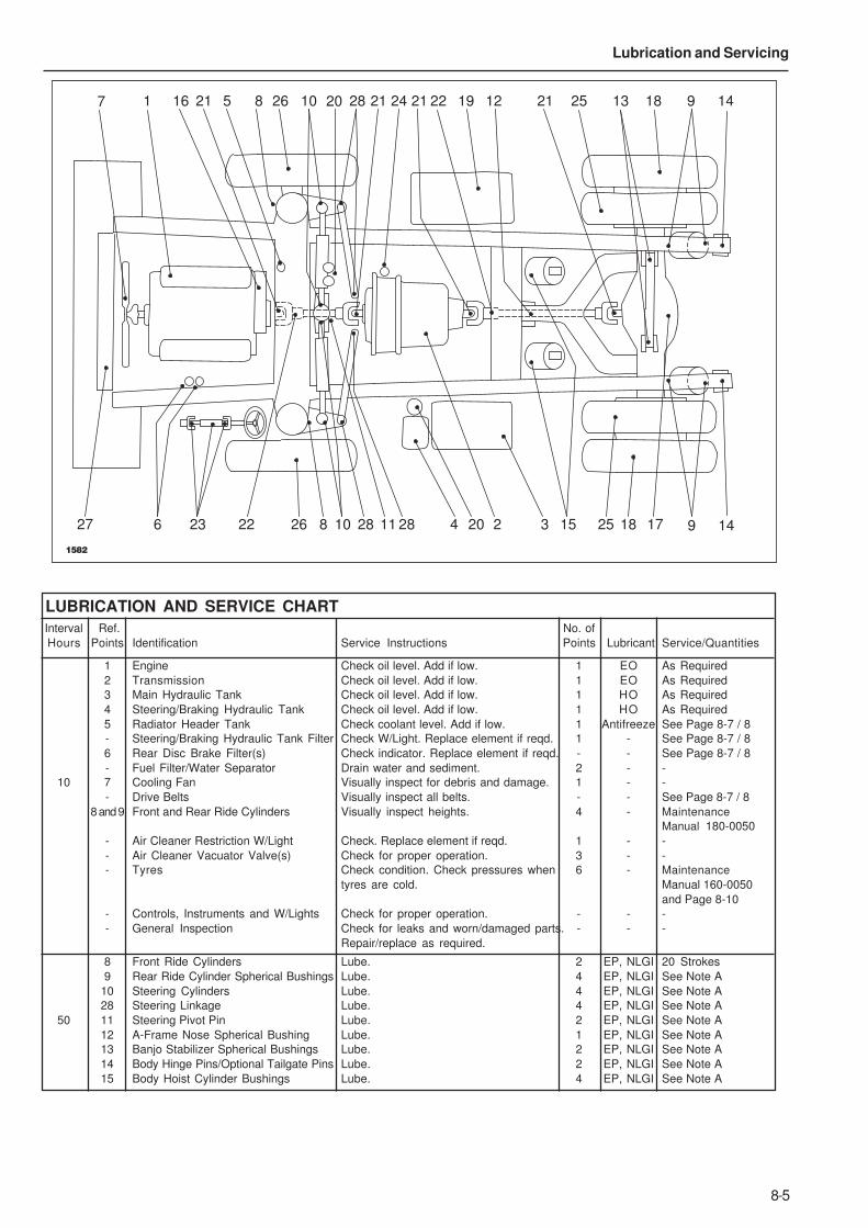
8-5
Lubrication and Servicing
7 1 16 21 5 8 26 10 28 21 2124 22 19 12 21 25 13 18 9 14
9 1427 6 23 22 26 8 10 28 2811 4 20 2 3 15 25 18 17
20
1582
LUBRICATION AND SERVICE CHART
Interval Ref. No. of
Hours Points Identification Service Instructions Points Lubricant Service/Quantities
1 Engine Check oil level. Add if low. 1 EO As Required
2 Transmission Check oil level. Add if low. 1 EO As Required
3 Main Hydraulic Tank Check oil level. Add if low. 1 HO As Required
4 Steering/Braking Hydraulic Tank Check oil level. Add if low. 1 HO As Required
5 Radiator Header Tank Check coolant level. Add if low. 1 Antifreeze See Page 8-7 / 8
- Steering/Braking Hydraulic Tank Filter Check W/Light. Replace element if reqd. 1 - See Page 8-7 / 8
6 Rear Disc Brake Filter(s) Check indicator. Replace element if reqd. - - See Page 8-7 / 8
- Fuel Filter/Water Separator Drain water and sediment. 2 - -
10 7 Cooling Fan Visually inspect for debris and damage. 1 - -
- Drive Belts Visually inspect all belts. - - See Page 8-7 / 8
8 and 9 Front and Rear Ride Cylinders Visually inspect heights. 4 - Maintenance
Manual 180-0050
- Air Cleaner Restriction W/Light Check. Replace element if reqd. 1 - -
- Air Cleaner Vacuator Valve(s) Check for proper operation. 3 - -
- Tyres Check condition. Check pressures when 6 - Maintenance
tyres are cold. Manual 160-0050
and Page 8-10
- Controls, Instruments and W/Lights Check for proper operation. - - -
- General Inspection Check for leaks and worn/damaged parts. - - -
Repair/replace as required.
8 Front Ride Cylinders Lube. 2 EP, NLGI 20 Strokes
9 Rear Ride Cylinder Spherical Bushings Lube. 4 EP, NLGI See Note A
10 Steering Cylinders Lube. 4 EP, NLGI See Note A
28 Steering Linkage Lube. 4 EP, NLGI See Note A
50 11 Steering Pivot Pin Lube. 2 EP, NLGI See Note A
12 A-Frame Nose Spherical Bushing Lube. 1 EP, NLGI See Note A
13 Banjo Stabilizer Spherical Bushings Lube. 2 EP, NLGI See Note A
14 Body Hinge Pins/Optional Tailgate Pins Lube. 2 EP, NLGI See Note A
15 Body Hoist Cylinder Bushings Lube. 4 EP, NLGI See Note A
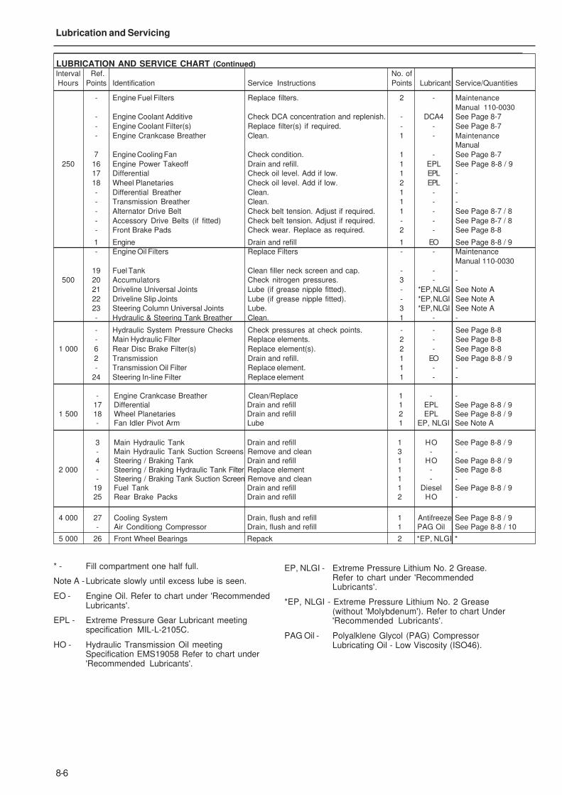
8-6
Lubrication and Servicing
LUBRICATION AND SERVICE CHART (Continued)
Interval Ref. No. of
Hours Points Identification Service Instructions Points Lubricant Service/Quantities
- Engine Fuel Filters Replace filters. 2 - Maintenance
Manual 110-0030
- Engine Coolant Additive Check DCA concentration and replenish. - DCA4 See Page 8-7
- Engine Coolant Filter(s) Replace filter(s) if required. - - See Page 8-7
- Engine Crankcase Breather Clean. 1 - Maintenance
Manual
7 Engine Cooling Fan Check condition. 1 - See Page 8-7
250 16 Engine Power Takeoff Drain and refill. 1 EPL See Page 8-8 / 9
17 Differential Check oil level. Add if low. 1 EPL -
18 Wheel Planetaries Check oil level. Add if low. 2 EPL -
- Differential Breather Clean. 1 - -
- Transmission Breather Clean. 1 - -
- Alternator Drive Belt Check belt tension. Adjust if required. 1 - See Page 8-7 / 8
- Accessory Drive Belts (if fitted) Check belt tension. Adjust if required. - - See Page 8-7 / 8
- Front Brake Pads Check wear. Replace as required. 2 - See Page 8-8
1 Engine Drain and refill 1 EO See Page 8-8 / 9
- Engine Oil Filters Replace Filters - - Maintenance
Manual 110-0030
19 Fuel Tank Clean filler neck screen and cap. - - -
500 20 Accumulators Check nitrogen pressures. 3 - -
21 Driveline Universal Joints Lube (if grease nipple fitted). - *EP, NLGI See Note A
22 Driveline Slip Joints Lube (if grease nipple fitted). - *EP, NLGI See Note A
23 Steering Column Universal Joints Lube. 3 *EP, NLGI See Note A
- Hydraulic & Steering Tank Breather Clean. 1 - -
- Hydraulic System Pressure Checks Check pressures at check points. - - See Page 8-8
- Main Hydraulic Filter Replace elements. 2 - See Page 8-8
1 000 6 Rear Disc Brake Filter(s) Replace element(s). 2 - See Page 8-8
2 Transmission Drain and refill. 1 EO See Page 8-8 / 9
- Transmission Oil Filter Replace element. 1 - -
24 Steering In-line Filter Replace element 1 - -
- Engine Crankcase Breather Clean/Replace 1 - -
17 Differential Drain and refill 1 EPL See Page 8-8 / 9
1 500 18 Wheel Planetaries Drain and refill 2 EPL See Page 8-8 / 9
- Fan Idler Pivot Arm Lube 1 EP, NLGI See Note A
3 Main Hydraulic Tank Drain and refill 1 HO See Page 8-8 / 9
- Main Hydraulic Tank Suction Screens Remove and clean 3 - -
4 Steering / Braking Tank Drain and refill 1 HO See Page 8-8 / 9
2 000 - Steering / Braking Hydraulic Tank Filter Replace element 1 - See Page 8-8
- Steering / Braking Tank Suction Screen Remove and clean 1 - -19 Fuel Tank Drain and refill 1 Diesel See Page 8-8 / 9
25 Rear Brake Packs Drain and refill 2 HO -
4 000 27 Cooling System Drain, flush and refill 1 Antifreeze See Page 8-8 / 9- Air Conditiong Compressor Drain, flush and refill 1 PAG Oil See Page 8-8 / 10
5 000 26 Front Wheel Bearings Repack 2 *EP, NLGI *
* - Fill compartment one half full.
Note A -Lubricate slowly until excess lube is seen.
EO - Engine Oil. Refer to chart under 'RecommendedLubricants'.
EPL - Extreme Pressure Gear Lubricant meetingspecification MIL-L-2105C.
HO - Hydraulic Transmission Oil meetingSpecification EMS19058 Refer to chart under'Recommended Lubricants'.
EP, NLGI - Extreme Pressure Lithium No. 2 Grease.Refer to chart under 'RecommendedLubricants'.
*EP, NLGI - Extreme Pressure Lithium No. 2 Grease(without 'Molybdenum'). Refer to chart Under'Recommended Lubricants'.
PAG Oil - Polyalklene Glycol (PAG) CompressorLubricating Oil - Low Viscosity (ISO46).
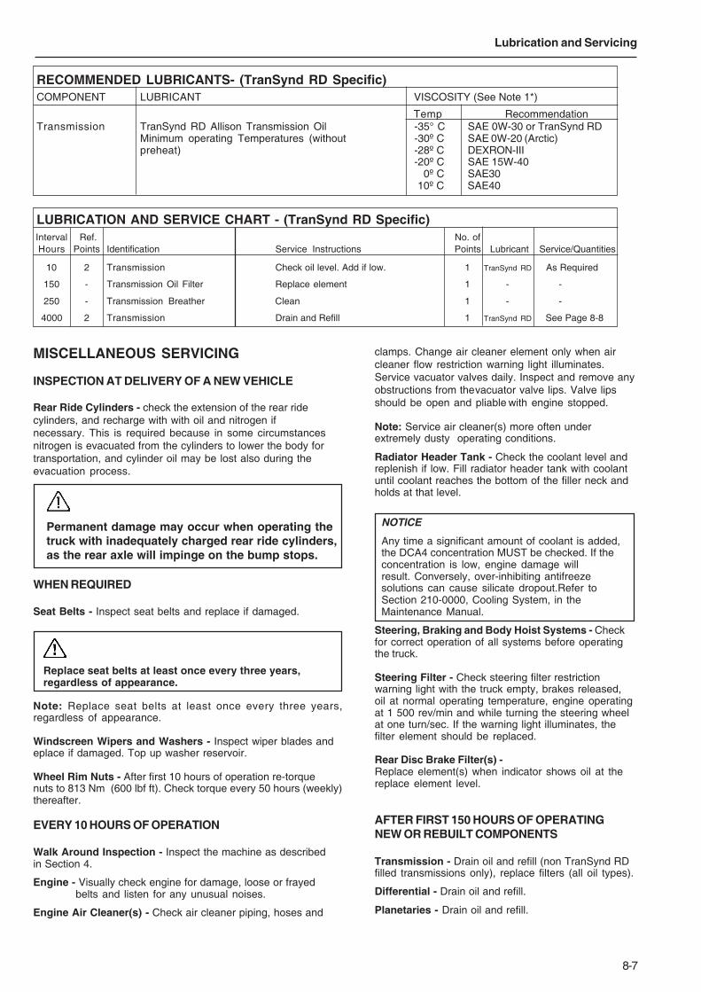
8-7
Lubrication and Servicing
RECOMMENDED LUBRICANTS- (TranSynd RD Specific)COMPONENT LUBRICANT VISCOSITY (See Note 1*)
Temp RecommendationTransmission TranSynd RD Allison Transmission Oil -35° C SAE 0W-30 or TranSynd RD
Minimum operating Temperatures (without -30º C SAE 0W-20 (Arctic)preheat) -28º C DEXRON-III
-20º C SAE 15W-40-00º C SAE30-10º C SAE40
LUBRICATION AND SERVICE CHART - (TranSynd RD Specific)Interval Ref. No. ofHours Points Identification Service Instructions Points Lubricant Service/Quantities
10 2 Transmission Check oil level. Add if low. 1 TranSynd RD As Required
150 - Transmission Oil Filter Replace element 1 - -
250 - Transmission Breather Clean 1 - -
4000 2 Transmission Drain and Refill 1 TranSynd RD See Page 8-8
MISCELLANEOUS SERVICING
INSPECTION AT DELIVERY OF A NEW VEHICLE
Rear Ride Cylinders - check the extension of the rear ridecylinders, and recharge with with oil and nitrogen ifnecessary. This is required because in some circumstancesnitrogen is evacuated from the cylinders to lower the body fortransportation, and cylinder oil may be lost also during theevacuation process.
Permanent damage may occur when operating thetruck with inadequately charged rear ride cylinders,as the rear axle will impinge on the bump stops.
WHEN REQUIRED
Seat Belts - Inspect seat belts and replace if damaged.
Replace seat belts at least once every three years,regardless of appearance.
Note: Replace seat belts at least once every three years,regardless of appearance.
Windscreen Wipers and Washers - Inspect wiper blades andeplace if damaged. Top up washer reservoir.
Wheel Rim Nuts - After first 10 hours of operation re-torquenuts to 813 Nm (600 lbf ft). Check torque every 50 hours (weekly)thereafter.
EVERY 10 HOURS OF OPERATION
Walk Around Inspection - Inspect the machine as describedin Section 4.
Engine - Visually check engine for damage, loose or frayedbelts and listen for any unusual noises.
Engine Air Cleaner(s) - Check air cleaner piping, hoses and
clamps. Change air cleaner element only when aircleaner flow restriction warning light illuminates.Service vacuator valves daily. Inspect and remove anyobstructions from thevacuator valve lips. Valve lipsshould be open and pliable with engine stopped.
Note: Service air cleaner(s) more often underextremely dusty operating conditions.
Radiator Header Tank - Check the coolant level andreplenish if low. Fill radiator header tank with coolantuntil coolant reaches the bottom of the filler neck andholds at that level.
NOTICE
Any time a significant amount of coolant is added,the DCA4 concentration MUST be checked. If theconcentration is low, engine damage willresult. Conversely, over-inhibiting antifreezesolutions can cause silicate dropout.Refer toSection 210-0000, Cooling System, in theMaintenance Manual.
Steering, Braking and Body Hoist Systems - Checkfor correct operation of all systems before operatingthe truck.
Steering Filter - Check steering filter restrictionwarning light with the truck empty, brakes released,oil at normal operating temperature, engine operatingat 1 500 rev/min and while turning the steering wheelat one turn/sec. If the warning light illuminates, thefilter element should be replaced.
Rear Disc Brake Filter(s) -Replace element(s) when indicator shows oil at thereplace element level.
AFTER FIRST 150 HOURS OF OPERATINGNEW OR REBUILT COMPONENTS
Transmission - Drain oil and refill (non TranSynd RDfilled transmissions only), replace filters (all oil types).
Differential - Drain oil and refill.
Planetaries - Drain oil and refill.

8-8
Lubrication and Servicing
Engine Fuel Pre-filter - Replace fuel pre-filter.
Cooling Fan - Visually check the fan for cracks, looserivets, and bent or loose blades. Check fan mountingand tighten if required. Replace any fan that is damaged.
Note: The fan belt is maintained to the correct belttension by a spring-loaded idler arm, therefore, thereis no need to check or adjust belt tension.
Drive Belts - Visually check the belts and replace if theyare cracked or frayed. Adjust belts that have a glazed orshiny surface which indicates belt slippage. Correctlyinstalled and tensioned belts will show even pulley andbelt wear. Refer to Section 110-0030, Engine andMounting, in the Maintenance Manual for drive belttension and adjustment of new and used drive belts.
Front Brakes - Check pads and discs for wear andreplace where necessary.
Note: This service interval applies to normal driving.Check more frequently under more severe conditions.Thickness of pad friction material should never beallowed to wear below 3 mm (0.12 in).
EVERY 1000 HOURS OF OPERATION
Hydraulic System Pressure Checks - Check all steering,body and braking system pressures.
Note: Instructions for checking pressure, and locations ofpressure check points, are contained in the relevantMaintenance manual section. If the pressures are outwith thespecified settings then components in the relevant systemshould be inspected, repaired or replaced to ensure thecorrect operation of the system. All safety instructions in therelevant sections should be strictly adhered to.
Main Hydraulic Filter - Clean filter housing and install newelement.
Rear Disc Brake Filter(s) - Replace filter element(s) whenindicator sight gauge shows replacement is necessary, orafter 1 000 hours of operation, whichever comes first.
Steering In-line Filter - Clean the filter housing and install anew element when indicated, or after 1000 hours of operation,whichever occurs first.
EVERY 2000 HOURS OF OPERATION
Steering Filter - Clean filter housing and install new elementwhen indicated, or after 2000 hours of operation, whichevercomes first.
ENGINES AND TRANSMISSIONS
All information contained in the “Lubrication and Service Chart”was extracted from the relevant manufacturers ‘Operation andMaintenance Manual’, and was correct at time of publication.User should ensure that information contained in this chartreflects the information shown in the relevent manufacturers‘Operation and Maintenance Manual’.Maintenance Procedures should be carried out in conjunctionwith any additional procedures in the relevant manufacturers‘Operation and Maintenance Manual’, at the intervalsspecified.
SERVICE CAPACITIES
Ref. TR100Points Identification Lubricant litres US gal
1 Engine Crankcase and Filters EO 134 35.4
2 Transmission and Filters EO / 100 26
TranSynd RD
3 Main Hydraulic Tank HO 297 78.5
- Main Hydraulic System HO 557 147.1
4 Steering Hydraulic Tank HO 61 16
- Steering Hydraulic System HO 72 19
27 Cooling System Coolant 304 80.3
19 Fuel Tank Diesel 1 275 336.3
8 Front Ride Cylinders (Each) HO 27 7.1
9 Rear Ride Cylinders (Each) HO 18 4.8
16 Engine Power Takeoff EPL 1.5 0.4
17 Differential EPL 61 16.1
18 Wheel Planetaries (Total) EPL 57 15.1
- Air Conditioning Compressor PAG Oil 0.135 0.036
EVERY 250 HOURS OF OPERATION
Oil Can Points - Oil accelerator linkage, hinges, and otherworking parts with engine oil.
Coolant Additive - Check and replenish DCA4concentration as described in Section 210-0000, CoolingSystem, in the Maintenance Manual.
Coolant Filter(s) - Replace coolant filter(s) if required.When testing the DCA4 concentration, depending on thelevel of DCA4, the coolant filter(s) may not necessarilyhave to be changed. Refer to Section210-0000, Cooling System, in the Maintenance Manual.
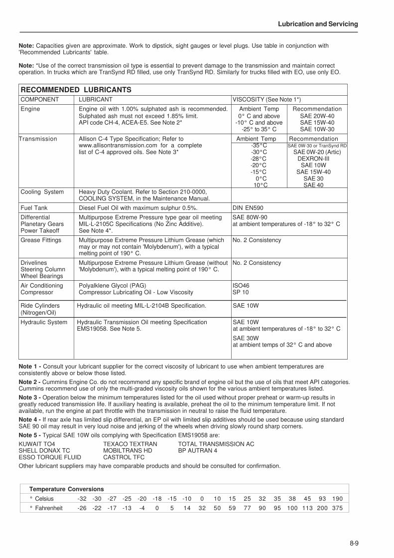
8-9
Lubrication and Servicing
RECOMMENDED LUBRICANTS
COMPONENT LUBRICANT VISCOSITY (See Note 1*)
Engine Engine oil with 1.00% sulphated ash is recommended. Ambient Temp RecommendationSulphated ash must not exceed 1.85% limit. 0° C and above SAE 20W-40API code CH-4, ACEA-E5. See Note 2* -10° C and above SAE 15W-40
-25° to 35° C SAE 10W-30
Transmission Allison C-4 Type Specification; Refer to Ambient Temp Recommendationwww.allisontransmission.com for a complete -35°C SAE 0W-30 or TranSynd RD
list of C-4 approved oils. See Note 3* -30°C SAE 0W-20 (Artic) -28°C DEXRON-III -20°C SAE 10W -15°C SAE 15W-40 0°C SAE 30 10°C SAE 40
Cooling System Heavy Duty Coolant. Refer to Section 210-0000,COOLING SYSTEM, in the Maintenance Manual.
Fuel Tank Diesel Fuel Oil with maximum sulphur 0.5%. DIN EN590
Differential Multipurpose Extreme Pressure type gear oil meeting SAE 80W-90Planetary Gears MIL-L-2105C Specifications (No Zinc Additive). at ambient temperatures of -18° to 32° CPower Takeoff See Note 4*.
Grease Fittings Multipurpose Extreme Pressure Lithium Grease (which No. 2 Consistencymay or may not contain 'Molybdenum'), with a typicalmelting point of 190° C.
Drivelines Multipurpose Extreme Pressure Lithium Grease (without No. 2 ConsistencySteering Column 'Molybdenum'), with a typical melting point of 190° C.Wheel Bearings
Air Conditioning Polyalklene Glycol (PAG) ISO46Compressor Compressor Lubricating Oil - Low Viscosity SP 10
Ride Cylinders Hydraulic oil meeting MIL-L-2104B Specification. SAE 10W(Nitrogen/Oil)
Hydraulic System Hydraulic Transmission Oil meeting Specification SAE 10WEMS19058. See Note 5. at ambient temperatures of -18° to 32° C
SAE 30Wat ambient temps of 32° C and above
Note: Capacities given are approximate. Work to dipstick, sight gauges or level plugs. Use table in conjunction with'Recommended Lubricants' table.
Note: *Use of the correct transmission oil type is essential to prevent damage to the transmission and maintain correctoperation. In trucks which are TranSynd RD filled, use only TranSynd RD. Similarly for trucks filled with EO, use only EO.
Note 1 - Consult your lubricant supplier for the correct viscosity of lubricant to use when ambient temperatures areconsistently above or below those listed.
Note 2 - Cummins Engine Co. do not recommend any specific brand of engine oil but the use of oils that meet API categories.Cummins recommend use of only the multi-graded viscosity oils shown for the various ambient temperatures listed.
Note 3 - Operation below the minimum temperatures listed for the oil used without proper preheat or warm-up results ingreatly reduced transmission life. If auxiliary heating is available, preheat the oil to the minimum temperature limit. If notavailable, run the engine at part throttle with the transmission in neutral to raise the fluid temperature.
Note 4 - If rear axle has limited slip differential, an EP oil with limited slip additives should be used because using standardSAE 90 oil may result in very loud noise and jerking of the wheels when driving slowly round sharp corners.
Note 5 - Typical SAE 10W oils complying with Specification EMS19058 are:
KUWAIT TO4 TEXACO TEXTRAN TOTAL TRANSMISSION ACSHELL DONAX TC MOBILTRANS HD BP AUTRAN 4ESSO TORQUE FLUID CASTROL TFC
Other lubricant suppliers may have comparable products and should be consulted for confirmation.
Temperature Conversions
° Celsius -32 -30 -27 -25 -20 -18 -15 -10 0 10 15 25 32 35 38 45 93 190
° Fahrenheit -26 -22 -17 -13 -4 0 5 14 32 50 59 77 90 95 100 113 200 375
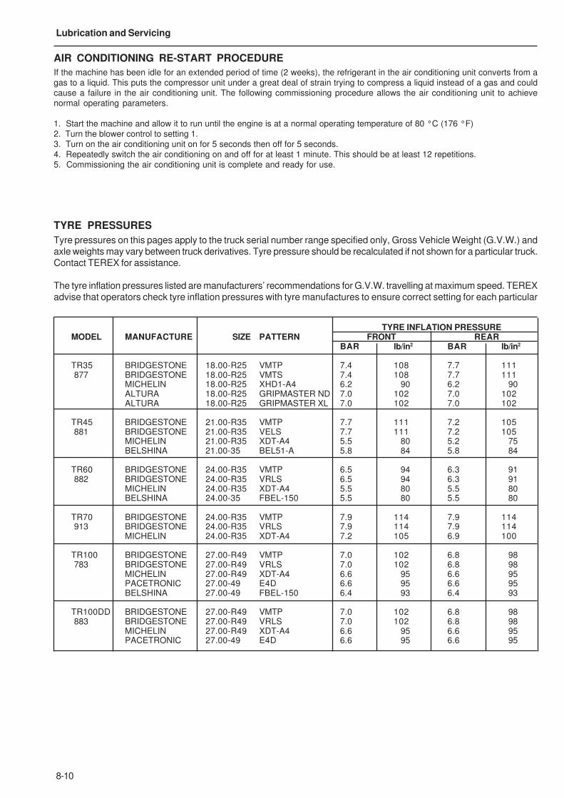
8-10
Lubrication and Servicing
AIR CONDITIONING RE-START PROCEDURE
If the machine has been idle for an extended period of time (2 weeks), the refrigerant in the air conditioning unit converts from agas to a liquid. This puts the compressor unit under a great deal of strain trying to compress a liquid instead of a gas and couldcause a failure in the air conditioning unit. The following commissioning procedure allows the air conditioning unit to achievenormal operating parameters.
1. Start the machine and allow it to run until the engine is at a normal operating temperature of 80 °C (176 °F)2. Turn the blower control to setting 1.3. Turn on the air conditioning unit on for 5 seconds then off for 5 seconds.4. Repeatedly switch the air conditioning on and off for at least 1 minute. This should be at least 12 repetitions.5. Commissioning the air conditioning unit is complete and ready for use.
TYRE PRESSURES
Tyre pressures on this pages apply to the truck serial number range specified only, Gross Vehicle Weight (G.V.W.) andaxle weights may vary between truck derivatives. Tyre pressure should be recalculated if not shown for a particular truck.Contact TEREX for assistance.
The tyre inflation pressures listed are manufacturers’ recommendations for G.V.W. travelling at maximum speed. TEREXadvise that operators check tyre inflation pressures with tyre manufactures to ensure correct setting for each particular
TYRE INFLATION PRESSUREMODEL MANUFACTURE SIZE PATTERN FRONT REAR
BAR lb/in2 BAR lb/in2
TR35 BRIDGESTONE 18.00-R25 VMTP 7.4 108 7.7 111 877 BRIDGESTONE 18.00-R25 VMTS 7.4 108 7.7 111
MICHELIN 18.00-R25 XHD1-A4 6.2 90 6.2 90ALTURA 18.00-R25 GRIPMASTER ND 7.0 102 7.0 102ALTURA 18.00-R25 GRIPMASTER XL 7.0 102 7.0 102
TR45 BRIDGESTONE 21.00-R35 VMTP 7.7 111 7.2 105 881 BRIDGESTONE 21.00-R35 VELS 7.7 111 7.2 105
MICHELIN 21.00-R35 XDT-A4 5.5 80 5.2 75BELSHINA 21.00-35 BEL51-A 5.8 84 5.8 84
TR60 BRIDGESTONE 24.00-R35 VMTP 6.5 94 6.3 91 882 BRIDGESTONE 24.00-R35 VRLS 6.5 94 6.3 91
MICHELIN 24.00-R35 XDT-A4 5.5 80 5.5 80BELSHINA 24.00-35 FBEL-150 5.5 80 5.5 80
TR70 BRIDGESTONE 24.00-R35 VMTP 7.9 114 7.9 114 913 BRIDGESTONE 24.00-R35 VRLS 7.9 114 7.9 114
MICHELIN 24.00-R35 XDT-A4 7.2 105 6.9 100
TR100 BRIDGESTONE 27.00-R49 VMTP 7.0 102 6.8 98 783 BRIDGESTONE 27.00-R49 VRLS 7.0 102 6.8 98
MICHELIN 27.00-R49 XDT-A4 6.6 95 6.6 95PACETRONIC 27.00-49 E4D 6.6 95 6.6 95BELSHINA 27.00-49 FBEL-150 6.4 93 6.4 93
TR100DD BRIDGESTONE 27.00-R49 VMTP 7.0 102 6.8 98 883 BRIDGESTONE 27.00-R49 VRLS 7.0 102 6.8 98
MICHELIN 27.00-R49 XDT-A4 6.6 95 6.6 95PACETRONIC 27.00-49 E4D 6.6 95 6.6 95

9-1
9 - Technical Data

9-2
Technical Data
This Page Intentionally Left Blank
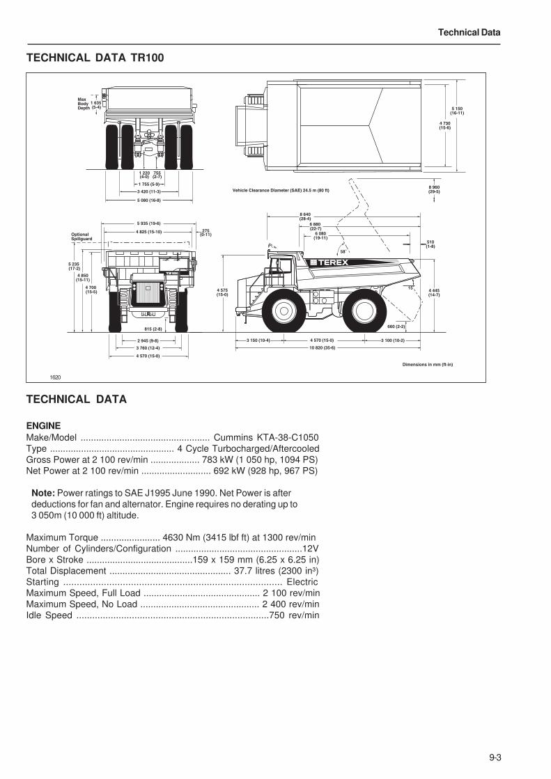
9-3
Technical Data
TECHNICAL DATA TR100
1620
TECHNICAL DATA
ENGINE
Make/Model .................................................. Cummins KTA-38-C1050
Type ................................................ 4 Cycle Turbocharged/Aftercooled
Gross Power at 2 100 rev/min ................... 783 kW (1 050 hp, 1094 PS)
Net Power at 2 100 rev/min ........................... 692 kW (928 hp, 967 PS)
Note: Power ratings to SAE J1995 June 1990. Net Power is after
deductions for fan and alternator. Engine requires no derating up to
3 050m (10 000 ft) altitude.
Maximum Torque ....................... 4630 Nm (3415 lbf ft) at 1300 rev/min
Number of Cylinders/Configuration .................................................12V
Bore x Stroke .........................................159 x 159 mm (6.25 x 6.25 in)
Total Displacement ............................................... 37.7 litres (2300 in³)
Starting ................................................................................. Electric
Maximum Speed, Full Load ............................................. 2 100 rev/min
Maximum Speed, No Load .............................................. 2 400 rev/min
Idle Speed .........................................................................750 rev/min
4 825 (15-10)
5 935 (19-6)
Optional
Spillguard
4 850
(15-11)
5 235
(17-2)
4 700
(15-5)
2 945 (9-8)
3 760 (12-4)
4 570 (15-0)
815 (2-8)
275(0-11)
755(2-7)
1 635
(5-4)
1 220(4-0)
5 080 (16-8)
1 755 (5-9)
3 420 (11-3)
Max
Body
Depth
4 575
(15-0)
Vehicle Clearance Diameter (SAE) 24.5 m (80 ft)
3 150 (10-4) 4 570 (15-0) 3 100 (10-2)
10 820 (35-6)
Dimensions in mm (ft-in)
4 445
(14-7)
6 880
(22-7)
8 640
(28-4)
6 080
(19-11)
8 960
(29-5)
660 (2-2)
510
(1-8)
15˚
58˚
4 730
(15-6)
5 150
(16-11)
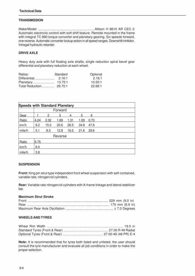
9-4
Technical Data
TRANSMISSION
Make/Model ..............................................................Allison H 8610 AR CEC 2
Automatic electronic control with soft shift feature. Remote mounted in the frame
with integral TC 890 torque converter and planetary gearing. Six speeds forward,
one reverse. Automatic converter lockup action in all speed ranges. Downshift inhibitor.
Intregal hydraulic retarder.
DRIVE AXLE
Heavy duty axle with full floating axle shafts, single reduction spiral bevel gear
differential and planetary reduction at each wheel.
Ratios: Standard Optional
Differential...................... 2.16:1 2.16:1
Planetary........................ 13.75:1 10.50:1
Total Reduction.............. 29.70:1 22.68:1
SUSPENSION
Front: King pin strut type independent front wheel suspension with self-contained,
variable rate, nitrogen/oil cylinders.
Rear: Variable rate nitrogen/oil cylinders with A-frame linkage and lateral stabilizer
bar.
Maximum Strut StrokeFront ..................................................................................... 229 mm (9.0 in)
Rear ........................................................................................ 175 mm (6.9 in)
Maximum Rear Axle Oscillation .................................................... ± 7.0 Degrees
WHEELS AND TYRES
Wheel Rim Width ................................................................................. 19.5 in
Standard Tyres (Front & Rear) ................................................. 27.00 R 49 Radial
Optional Tyres (Front & Rear) ............................................ 27.00-49 (48 PR) E-4
Note: It is recommended that for tyres both listed and unlisted, the user should
consult the tyre manufacturer and evaluate all job conditions in order to make the
proper selection.
Speeds with Standard Planetary
Forward
Gear 1 2 3 4 5 6
Ratio 4.24 2.32 1.69 1.31 1.00 0.73
km/h 8.2 15.0 20.6 26.5 34.8 47.6
mile/h 5.1 9.3 12.8 16.5 21.6 29.6
Reverse
Ratio 5.75
km/h 6.0
mile/h 3.8

9-5
Technical Data
BRAKES
ServiceAll hydraulic brake system control. Transmission mounted pressure
compensating pump provides hydraulic pressure for brakes and steering.
Independent circuits front and rear. Each circuit incorporates a nitrogen
accumulator which stores energy to provide consistent braking response.
Front Brake Circuit Pressure .........................................159 bar (2 300 lbf/in²)
Rear Brake Circuit Pressure ............................................. 52 bar (750 lbf/in²)
Accumulators:
Nitrogen Precharge Pressure ......................................... 55 bar (800 lbf/in²)
Front:Type ............................................................ Dry Disc with 1 calliper per wheel
Disc Diameter ......................................................................965 mm (38 in)
Pad Area, Total ...............................................................2 015 cm² (320 in²)
Rear:Type ..............................................................Oil cooled, multiple friction discs,
completely sealed from dirt and water.
Braking Surface, Total .............................................. 87 567 cm² (13 573 in²)
Parking
Application of rear brakes by springs in brake disc pack. Hydraulically released.
Hold-off Pressure ......................................................... 83 bar (1 200 lbf/in²)
Retardation
Modulated lever control of rear disc pack.
Retarder Actuation Pressure ...................................... up to 33 bar (480 lbf/in²)
Emergency
Push button solenoid control applies service and parking brakes. Automatically
applies when engine is switched off. Parking brake applies should system
pressure fall below a predetermined level.
Brakes conform to ISO 3450, SAE J1473.
STEERING SYSTEM
Independent hydrostatic steering with closed-centre steering valve,
accumulator and pressure compensating piston pump.
Accumulator provides uniform steering regardless of engine speed. In the event
of loss of engine power it provides steering of approximately two lock-to-lock
turns. A low pressure indicator light warns of system pressure below
83 bar (1 200 lbf/in²). Steering meets ISO 5010, SAE J53.
System Pressure ..........................................................159 bar (2 300 lbf/in²)
Relief Pressure ............................................................ 207 bar (3 000 lbf/in²)
Steering Cylinders ............................................. Double Acting, Single Stage
Accumulator:
Oil Capacity .......................................................... 16.4 litres (3.70 US gal)
Nitrogen Precharge Pressure .......................................... 55 bar (800 lbf/in²)
Steering Angle (Left and Right) ............................................................... 39°

9-6
Technical Data
Pump:
Type ........................................................................................ Piston
Capacity at 2 100 rev/min .............................1.57 litres/s (25 US gal/min)
BODY HYDRAULICS
Two body hoist cylinders are mounted between the frame rails. Cylinders
are two-stage with power down in the second stage.
System Relief Pressure ......................................... 190 bar (2 750 lbf/in²)
Pump:
Type ........................................................................................... Gear
Capacity at 2 100 rev/min ......................... 365 litres/min (97 US gal/ min)
Control Valve .......................................... Servo Controlled, Open Centre
Body Raise Time ................................................................14 Seconds
Body Lower Time ..................................................................18 Seconds
ELECTRICAL
Type .......................................................................... 24 Volt, Negative
Ground
Battery .......................................................... Four, 12 Volt, 210 Ah each,
Maintenance Free
Accessories ............................................................................. 24 Volt
Alternator ................................................................................. 70 Amp
Starter .................................................................................. Two 9 kW
BODY
Longitudinal 'V' type floor with integral transverse box-section stiffeners.
The body is exhaust heated and rests on resilient impact absorption pads.
Body wear surfaces are high hardness (360-440 BHN) abrasion resistant
steel. Yield strength of plates 1 000 MPa (145 000 lbf/in²).
Plate Thicknesses:
Floor ............................................................................ 19 mm (0.75 in)
Side ............................................................................. 10 mm (0.39 in)
Front, lower .................................................................. 10 mm (0.39 in)
ROPS Cabguard SAE J1040 Feb 86. ISO 3471
Volumes:
Struck (SAE) ............................................................. 41.6 m³ (54.4 yd³)
Heaped 2:1 (SAE) ...................................................... 57.0 m³ (74.5 yd³)
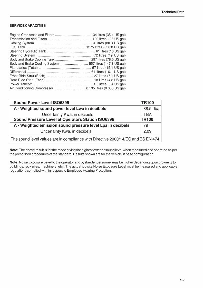
9-7
Technical Data
SERVICE CAPACITIES
Engine Crankcase and Filters ..................................... 134 litres (35.4 US gal)
Transmission and Filters .............................................. 100 litres (26 US gal)
Cooling System ........................................................ 304 litres (80.3 US gal)
Fuel Tank .............................................................. 1275 litres (336.8 US gal)
Steering Hydraulic Tank ................................................... 61 litres (16 US gal)
Steering System ........................................................... 72 litres (19 US gal)
Body and Brake Cooling Tank ..................................... 297 litres (78.5 US gal)
Body and Brake Cooling System .............................. 557 litres (147.1 US gal)
Planetaries (Total) ....................................................... 57 litres (15.1 US gal)
Differential .................................................................. 61 litres (16.1 US gal)
Front Ride Strut (Each) ................................................. 27 litres (7.1 US gal)
Rear Ride Strut (Each) .................................................. 18 litres (4.8 US gal)
Power Takeoff ................................................................1.5 litres (0.4 US gal)
Air Conditioning Compressor ................................. 0.135 litres (0.036 US gal)
Note: The above result is for the mode giving the highest exterior sound level when measured and operated as per
the prescribed procedures of the standard. Results shown are for the vehicle in base configuration.
Note: Noise Exposure Level to the operator and bystander personnel may be higher depending upon proximity to
buildings, rock piles, machinery, etc.. The actual job site Noise Exposure Level must be measured and applicable
regulations complied with in respect to Employee Hearing Protection.
Sound Power Level ISO6395 TR100
A - Weighted sound power level Lwa in decibels 88.5 dba
Uncertainty Kwa, in decibels TBA
Sound Pressure Level at Operators Station ISO6396 TR100
A - Weighted emission sound pressure level Lpa in decibels 79
Uncertainty Kwa, in decibels 2.09
The sound level values are in compliance with Directive 2000/14/EC and BS EN 474.
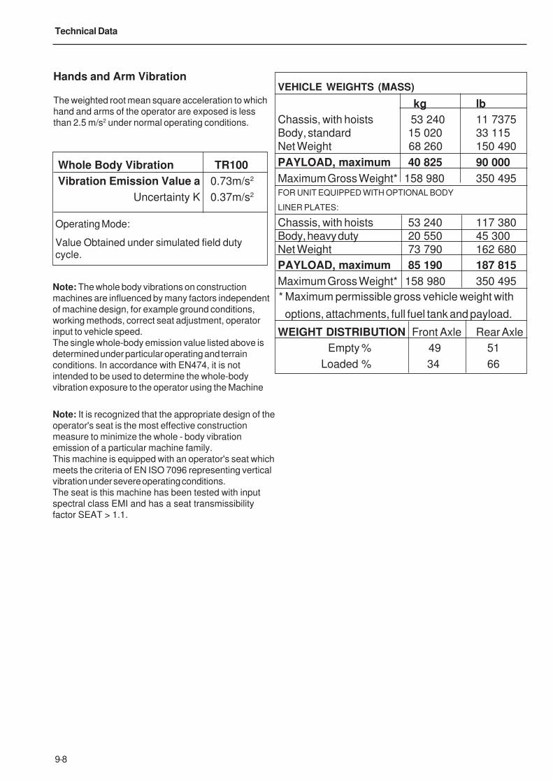
9-8
Technical Data
Note: The whole body vibrations on construction
machines are influenced by many factors independent
of machine design, for example ground conditions,
working methods, correct seat adjustment, operator
input to vehicle speed.
The single whole-body emission value listed above is
determined under particular operating and terrain
conditions. In accordance with EN474, it is not
intended to be used to determine the whole-body
vibration exposure to the operator using the Machine
Note: It is recognized that the appropriate design of the
operator's seat is the most effective construction
measure to minimize the whole - body vibration
emission of a particular machine family.
This machine is equipped with an operator's seat which
meets the criteria of EN ISO 7096 representing vertical
vibration under severe operating conditions.
The seat is this machine has been tested with input
spectral class EMI and has a seat transmissibility
factor SEAT > 1.1.
Hands and Arm Vibration
The weighted root mean square acceleration to which
hand and arms of the operator are exposed is less
than 2.5 m/s2 under normal operating conditions.
Whole Body Vibration TR100
Vibration Emission Value a 0.73m/s2
Uncertainty K 0.37m/s2
Operating Mode:
Value Obtained under simulated field dutycycle.
VEHICLE WEIGHTS (MASS)
kg lb
Chassis, with hoists 53 240 11 7375
Body, standard 15 020 33 115
Net Weight 68 260 150 490
PAYLOAD, maximum 40 825 90 000
Maximum Gross Weight* 158 980 350 495
FOR UNIT EQUIPPED WITH OPTIONAL BODY
LINER PLATES:
Chassis, with hoists 53 240 117 380
Body, heavy duty 20 550 45 300
Net Weight 73 790 162 680
PAYLOAD, maximum 85 190 187 815
Maximum Gross Weight* 158 980 350 495
WEIGHT DISTRIBUTION Front Axle Rear Axle
Empty % 49 51
Loaded % 34 66
* Maximum permissible gross vehicle weight with
options, attachments, full fuel tank and payload.

10-1
Symbol Identification
10 - Symbol Identification

10-2
Symbol Identification
This Page Intentionally Left Blank
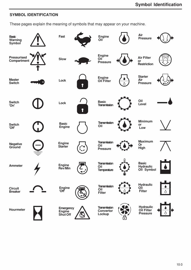
10-3
Symbol Identification
SYMBOL IDENTIFICATION
These pages explain the meaning of symbols that may appear on your machine.
PressurisedCompartment
MasterSwitch
Switch'On'
Switch'Off'
NegativeGround
Ammeter
CircuitBreaker
Hourmeter
Basic WarningSymbol
Fast
Slow
Lock
Lock
BasicEngine
EngineStarter
EngineRev/Min
Engine'Off'
EmergencyEngineShut Off
EngineOil
EngineOilPressure
EngineOil Filter
BasicTransmission
TransmissionOil
TransmissionOilPressure
TransmissionOilTemperature
TransmissionOilFilter
TransmissionConvertorLockup
AirPressure
Air FilterorRestriction
StarterAirPressure
OilLevel
Minimumor Low
MaximumOrHigh
BasicHydraulicOil Symbol
HydraulicOil Filter
HydraulicOil FilterPressure
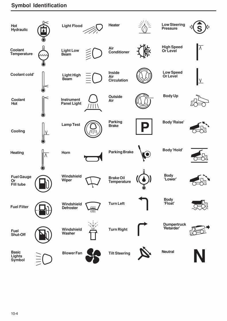
10-4
Symbol Identification
P
S
N
HotHydraulic
CoolantTemperature
Coolant cold'
CoolantHot
Cooling
Heating
Fuel GaugeOrFill tube
Fuel Filter
FuelShut-Off
BasicLightsSymbol
Light Flood
Light LowBeam
Light HighBeam
InstrumentPanel Light
Lamp Test
Horn
WindshieldWiper
WindshieldDefroster
WindshieldWasher
Blower Fan
Heater
AirConditioner
InsideAirCirculation
OutsideAir
ParkingBrake
Parking Brake
Brake OilTemperature
Turn Left
Turn Right
Tilt Steering
Low SteeringPressure
High SpeedOr Level
Low SpeedOr Level
Body Up
Body 'Raise'
Body 'Hold'
Body'Lower'
Body'Float'
Neutral
Dumpertruck'Retarder'

10-5
Symbol Identification
STOP
H
L
Lift Point
Do Not Lift
Forward
Reverse
Clutch'Engaged'
Clutch'Disengaged'
BrakeAppliedClutchEngaged
BrakeAppliedClutchDisengaged
Water inFuel
Wait toStart
BowlSuspension
Maintainance
TransmissionConverter
Brake airPressure
EngineCheck
EngineStop
TransOver Speed
Batterypower
EngineAir Filter
BrakeCoolingOilPressure
BrakeCoolingOilTemperature
Body Up
Trans.Oil Temp.
DropOil Temp
Drop OilPressure
Trans.retarder
EngineBrake
DropboxHigh Ratio
DropboxLow ratio

10-6
Symbol Identification
NOTES

10-7
Symbol Identification
NOTES

10-8
Symbol Identification
NOTES