tpl pull fuse assembly user’s manual - apc.com · tpl pull fuse assembly user’s manual...
TRANSCRIPT
TPL PULL FUSE ASSEMBLY
User’s Manual (Document # 990-9220)

Page ii TPL Pull Fuse Assembly User’s Manual (990-9220)
Table of Contents Table of Contents.......................................................................ii Figures and Tables ...................................................................iii 1 Safety First!..........................................................................2
1.1. Warning Symbols............................................................................................2 1.2. General Precautions: ......................................................................................2
2 Introduction .........................................................................3 2.1. General Information ........................................................................................3 2.2. How to Use This Manual.................................................................................3
3 Installation ...........................................................................4 3.1. Unpacking Equipment.....................................................................................4 3.2. Mechanical Installation ...................................................................................5 3.3. DC Input Power Wiring ...................................................................................7 3.4. Jumper Configuration .....................................................................................9 3.5. Alarm and Control Connections ....................................................................11 3.6. Install GMT Fuse. .........................................................................................12 3.7. Power-up and Checkout ...............................................................................12
4 Operation ...........................................................................13 4.1. Technical Description ...................................................................................13 4.2. Front Panel LED indicator.............................................................................13 4.3. Alarm relays..................................................................................................13
5 Specifications ....................................................................15 5.1. DC Input:.......................................................................................................15 5.2. Controls and Indicators: ................................................................................15 5.3. Mechanical:...................................................................................................15 5.4. Environmental:..............................................................................................15
6 APC Worldwide Customer Support .................................16 7 Warranty.............................................................................17

TPL Pull Fuse Assembly User’s Manual (990-9220) Page iii
Figures and Tables
Figure 3-2. Front view with dimensions of voltage bus bars..........................................5 Figure 3-3. Front view and Side view. ...........................................................................6 Figure 3.4. +24 Volt System Wiring Diagram ................................................................7 Figure 3.5. -48 Volt System Wiring Diagram .................................................................8 Figure 3-6. –48 Volt System Jumper Configuration.......................................................9 Figure 3-7. +24 Volt System Jumper Configuration.....................................................10 Figure 3-10. Alarm connections. .................................................................................11 Figure 4.1. Alarm Relay Circuit (De-energized condition, Fuse Blown).......................13 Figure 4-2. Alarm relay circuit (Energized Condition, Fuse Not Blown).......................14
Revision History
Revision Date By Description
A MAY 2002 JPM Initial release
Page 2 TPL Pull Fuse Assembly User’s Manual (990-9220)
1 Safety First! It is very important to follow all safety procedures when unpacking, installing and operating any sort of power equipment. 1.1. Warning Symbols
CAUTION: An indication that special care is required to prevent personal injury, equipment damage or misuse.
WARNING: An indication of a potential electrical hazard that may cause serious personal injury or death, catastrophic equipment damage or site destruction.
1.2. General Precautions:
WARNING: Hazardous energy levels are present on bare conductors in the +24VDC / -48VDC distribution connection area of the plant. Accidental shorting of distribution conductors can cause arcing and high currents that can cause serious burns or other physical harm. It is recommended that:
• = Any jewelry, rings or watches be removed while working on this equipment.
• = Handles of all wrenches, screwdrivers, cutters and pliers are insulated.
• = Shafts of screwdrivers be wrapped in electrical tape or otherwise insulated
WARNING: Ensure that all of the external DC circuit breakers are in the OFF position prior to connecting service to the fuse cabinet. Confirm that all voltages have been removed including any battery sources before proceeding.
Specific CAUTION and WARNING will be placed in manual where appropriate.

TPL Pull Fuse Assembly User’s Manual (990-9220) Page 3
2 Introduction 2.1. General Information The TPL Fuse Alarm Card was designed for +24VDC or –48VDC operation. The Alarm Card monitors a TPL Fuse, and will report an alarm when blown. The TPL Fuse Alarm Card was designed so that the relay de-energizes upon a fault. The alarm card is mounted inside the front door of a fiberglass cabinet, which measures 15.73” X 13.85” X 7.71”. The GMT Fuse and green LED both stick out of the cabinet’s front door.
2.2. How to Use This Manual Each section of this manual can be read in any order and should provide a complete explanation of the subject described by the title. However, the sequence of the sections is designed to provide a typical step-by-step process for successful installation and use of the equipment.
Safety First! Safety symbol description and general precautions.
Introduction Brief system preview and explanation of manual usage.
Installation How to unpack, install and commission the equipment of initial use.
Operation Specifics of controls settings and indicators used to operate the unit.
Specifications Power plant and rectifier specifications.
APC Worldwide Customer Support
How to contact APC for customer support.
Warranty Equipment warranty terms and conditions.
Page 4 TPL Pull Fuse Assembly User’s Manual (990-9220)
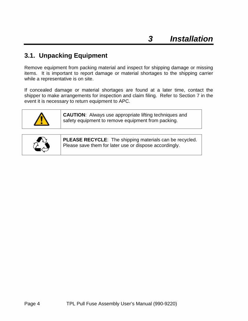
3 Installation 3.1. Unpacking Equipment Remove equipment from packing material and inspect for shipping damage or missing items. It is important to report damage or material shortages to the shipping carrier while a representative is on site. If concealed damage or material shortages are found at a later time, contact the shipper to make arrangements for inspection and claim filing. Refer to Section 7 in the event it is necessary to return equipment to APC.
CAUTION: Always use appropriate lifting techniques and safety equipment to remove equipment from packing.
PLEASE RECYCLE: The shipping materials can be recycled. Please save them for later use or dispose accordingly.

TPL Pull Fuse Assembly User’s Manual (990-9220) Page 5
3.2. Mechanical Installation The fiberglass cabinet has four .281” mounting holes as can be seen from Figure 3-2. The type of bolts used to mount the cabinet depends on where the cabinet will be mounted and what type of surface it’s mounted to. Figure 3-2 also shows the input voltage bars’ bolt spacing (in inches). Figure 3-3 gives the cabinet’s height, width, and depth, also in inches. Careful consideration should be given to cable routing and grounding prior to installation. It is recommended that the distribution equipment be mounted in a location with access limited to qualified personnel in accordance with NEC or other local authority having jurisdiction over safety.
Figure 3-2. Front view with dimensions of voltage bus bars.

Page 6 TPL Pull Fuse Assembly User’s Manual (990-9220)
Figure 3-3. Front view and Side view.

TPL Pull Fuse Assembly User’s Manual (990-9220) Page 7
3.3. DC Input Power Wiring
+24 VOLT SYSTEM
MAKE GROUND CONNECTION OUTSIDE BOX BLACK RECTIFIER BUS RTN WIRE POWER CONNECTOR
J3 BATTERY BUS
Figure 3.4. +24 Volt System Wiring Diagram
TPL PULL FUSE +PWR GMT_RECT GMT_BATT -PWR GREEN
WIRE
GREEN WIRE
BLACK WIRE
RED WIRE
Page 8 TPL Pull Fuse Assembly User’s Manual (990-9220)
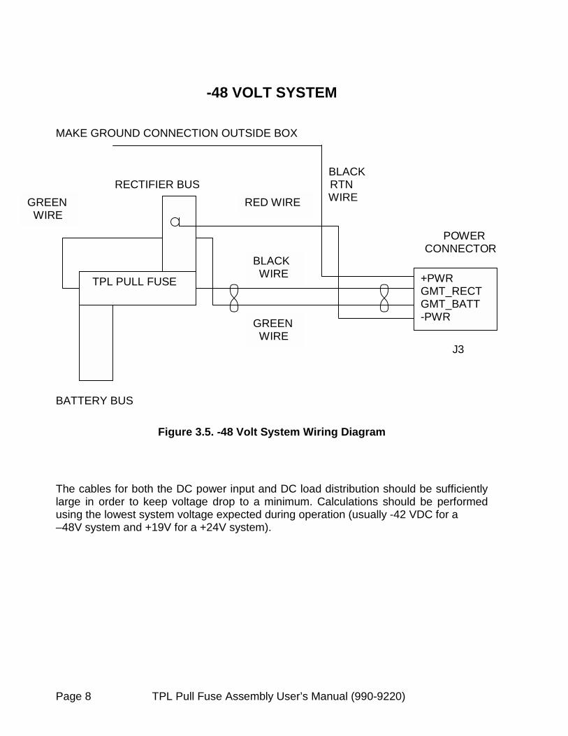
-48 VOLT SYSTEM
MAKE GROUND CONNECTION OUTSIDE BOX BLACK RECTIFIER BUS RTN WIRE POWER CONNECTOR
J3 BATTERY BUS
Figure 3.5. -48 Volt System Wiring Diagram The cables for both the DC power input and DC load distribution should be sufficiently large in order to keep voltage drop to a minimum. Calculations should be performed using the lowest system voltage expected during operation (usually -42 VDC for a –48V system and +19V for a +24V system).
TPL PULL FUSE +PWR GMT_RECT GMT_BATT -PWR GREEN
WIRE
GREEN WIRE
BLACK WIRE
RED WIRE

TPL Pull Fuse Assembly Us
3.4. Jumper Configuration
CAUTION: It is very important that the jumpers are placed properly on the circuit board. Failure to do so might cause the alarm relay to function falsely, the LED to overheat, or the alarm relay to overheat.
NOTE: JUMPERS ARE PROVIDED ON THE CIRCUIT BOARD. -48 Volt System Locate the 1 X 3 jumper J4. It should be near the bottom of the circuit board. PLACE THE JUMPER SO THAT PINS 2 AND 3 ON J4 ARE CONNECTED. Pin 1 is the pin farthest on the left, thereby making pin 2 in the middle and pin 3 the farthest on the right. DO NOT PUT ANY JUMPERS ON J5 AND J6.
Figure 3-6.
NccS
otice how pins 2 and 3 on J4 are onnected. Notice there are no onnections on J5 and J6 for a -48 Volt ystem.
er’s Manual (990-9220) Page 9
–48 Volt System Jumper Configuration.

Page 10 TPL Pull Fuse Assembly User’s Manual (990-9220)
+24 Volt System Locate the 1 X 3 jumper J4. It should be near the bottom of the circuit board. PLACE THE JUMPER SO THAT PINS 1 AND 2 ON J4 ARE CONNECTED. Pin 1 should be the pin farthest on the left, thereby making pin 2 in the middle and pin 3 the farthest on the right. Locate jumper J5. It should be located near the bottom of the circuit board. Place the jumper so that pins 1 and 2 on J5 are connected. Locate jumper J6. It should be located near the bottom of the circuit board. Place the jumper so that pins 1 and 2 on J6 are connected.
Figure 3-7. +24 Volt System Jumper Configuration.
Notice how pins 1 and 2 on J4 are connected. Also, notice there are connections on J5 and J6 for a +24 Volt System.

TPL Pull Fuse Assembly User’s Manual (990-9220) Pag
3.5. Alarm and Control Connections Alarm reports are provided via a form C, dry contact relay and a 3-position WAGO terminal block (WAGO part number 256-403), providing normally open, normally closed, and common contacts. The terminal block’s reference designator on the printed circuit board is J1. Under the normal condition (no alarm), the relay is energized (C is connected to NC). If possible, use the C-NC pair for alarm reporting.
Figure 3-10. Alarm connections.
I
Insert wire here.
nsert wire here
e 11

Page 12 TPL Pull Fuse Assembly User’s Manual (990-9220)
3.6. Install GMT Fuse.
WARNING: Hazardous energy levels are present on exposed areas of the GMT fuse. Accidental shorting can cause arcing and high currents that can cause serious burns or other physical harm.
The GMT fuse should be installed from the outside of the fiberglass cabinet. Insert the GMT into the slot on the front door of the cabinet. The GMT fuse is rated for 1 Amp. 3.7. Power-up and Checkout Before applying power to the system, make sure the following conditions exist.
• = Ensure the breakers supplying power to the unit are off at this time. • = Apply power to the unit by closing the circuit breakers to the unit. • = Turn on the loads if applicable.
TPL Pull Fuse Assembly User’s Manual (990-9220) Page 13
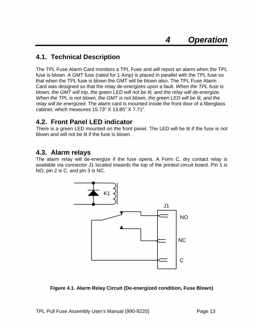
4 Operation 4.1. Technical Description The TPL Fuse Alarm Card monitors a TPL Fuse and will report an alarm when the TPL fuse is blown. A GMT fuse (rated for 1 Amp) is placed in parallel with the TPL fuse so that when the TPL fuse is blown the GMT will be blown also. The TPL Fuse Alarm Card was designed so that the relay de-energizes upon a fault. When the TPL fuse is blown, the GMT will trip, the green LED will not be lit, and the relay will de-energize. When the TPL is not blown, the GMT is not blown, the green LED will be lit, and the relay will be energized. The alarm card is mounted inside the front door of a fiberglass cabinet, which measures 15.73” X 13.85” X 7.71”. 4.2. Front Panel LED indicator There is a green LED mounted on the front panel. The LED will be lit if the fuse is not blown and will not be lit if the fuse is blown. 4.3. Alarm relays The alarm relay will de-energize if the fuse opens. A Form C, dry contact relay is available via connector J1 located towards the top of the printed circuit board. Pin 1 is NO, pin 2 is C, and pin 3 is NC.
K1
J1
NO
NC
C
Figure 4.1. Alarm Relay Circuit (De-energized condition, Fuse Blown)

Page 14 TPL Pull Fuse Assembly User’s Manual (990-9220)
K1
J1
NO
NC
C
Figure 4-2. Alarm relay circuit (Energized Condition, Fuse Not Blown)

TPL Pull Fuse Assembly User’s Manual (990-9220) Page 15
5 Specifications 5.1. DC Input: Nominal Input Voltage -48V system +24V system
-48 VDC +24VDC
Input Voltage Range -48V system +24V system
-40 to -60 VDC +19 to 30 VDC
Maximum Input Current -48V system +24V system
Refer to fuse specs (1200 amp fuse = 1200 amps, 800 amp fuse = 800 amps)
5.2. Controls and Indicators: Front Panel LED Indicates 1 Fuse OK Relay Contact Rating 2 Amp 30VDC 5.3. Mechanical: Height 15.73” (399.54mm) Width 13.85” (323.85mm) Depth 7.71” (195.83mm) Weight 26 lbs. (11.8kg) approximate Color Gray
5.4. Environmental: Operating Temperature -40°C to +70°C Operating Storage Temperature -40°C to +85°C Storage Operating Humidity 0% to 85% non-condensing Storage Humidity 0% to 95% non-condensing Operating Altitude Up to 3000 meters operating Storage Altitude Up to 10,000 meters storage

Page 16 TPL Pull Fuse Assembly User’s Manual (990-9220)
6 APC Worldwide Customer Support Customer Support for this or any other APC product is available at no charge. You can contact APC Customer Support in any of the following ways:
• = Use an APC web page to find answers to frequently asked questions (FAQs), to access documents in the APC Knowledge Base, and to submit customer support requests.
o http://www.apc.com (Corporate Headquarters) Connect by links to APC web pages for specific countries and regions, each of which provides customer support information.
o http://www.apc.com/support/ Submit customer support requests.
• = Contact Local or regional APC Customer Support by telephone or e-mail.
o For e-mail addresses and local, country-specific, customer support telephone numbers worldwide, refer to: http://www.apc.com/support/contact.
o For e-mail addresses and technical support telephone number of major APC regional customer support centers, use the following list:
APC Headquarters (US and Canada)
(1)(800) 800-4272 (1-800-800-4APC)
Latin America (1)(401) 789-5735 (US) [email protected]
Europe, Middle East, Africa
(353)(91)702020 (Ireland) [email protected]
Japan (03) 5434-2021 [email protected]
• = Contact the APC representative or other distributor from whom you purchased
your APC hardware device or APC software application for information on how to obtain local customer support.
TPL Pull Fuse Assembly User’s Manual (990-9220) Page 17
7 Warranty General Provisions APC DC Network Solutions Inc. warrants the power equipment and components it manufactures or sells against defective materials and workmanship for a period of TWO (2) YEARS from the date of shipment. Warranty Returns If initial physical inspection results in identification of a material or workmanship flaw(s) that could impair product performance as defined by APC ’s electrical and physical specification in effect at the time of shipment, and if this flaw(s) is not due to transportation damage or installation abuse, contact APC DC Network Solutions Inc. or call the 24-hour emergency number, (800) 800 4APC, to request assistance . You will be provided either a) an RMA number with instructions for return of the equipment or component(s) to the APC DC Network Solutions Inc. factory service center, FOB destination, freight pre-paid, for examination, or b) for non-returnable systems and equipment, notice to wait until an APC DC Network Solutions Inc. authorized service representative arrives at the site to inspect the equipment. Repaired or advance replacement modules or circuit components will normally be available within 24 to 48 hours of receipt of equipment or RMA. Warranty Repair or Replacement If, during the warranty period, the supplied equipment is found to be physically or electrically faulty due to defective materials or workmanship on the part of APC DC Network Solutions Inc., the defective product(s) or component(s) will be repaired or replaced at the sole option of APC DC Network Solutions Inc. without charge to the user for replacement materials or repair labor. (The procedure outlined above for contacting APC DC Network Solutions Inc. must be followed.) Costs incurred for replacement installation including, but not limited to, installation equipment, travel expenses of an APC DC Network Solutions Inc. representative(s), and costs of installation material transportation expenses are not the responsibility of APC DC Network Solutions Inc. Any replacement product(s) or component(s) shall only complete the remaining unused portion of the original warranty of the replaced product(s) or component(s)
Exclusions and Limitations 1. This warranty applies only to the original US domestic purchaser (user) and is not transferable internationally, except
with expressed written consent from APC DC Network Solutions Inc. headquarters in Dallas, Texas. 2. APC DC Network Solutions Inc. reserves the right to void the warranty if identification marks or serial numbers have
been removed or tampered with, or the defect is determined to have been caused by misuse, neglect, improper installation, environmental conditions, non-authorized repair, alteration, or accident.
3. This warranty does not cover physical damage due to the acts of nature or man that stress the equipment or component(s) beyond design limits and exert undesirable influence aside from normal wear and tear.
4. APC DC Network Solutions Inc. assumes no responsibility for any work accomplished or expenses incurred except with expressed written consent from APC DC Network Solutions Inc.
5. APC DC Network Solutions Inc. shall not be liable to the user (purchaser) or any third party for indirect, incidental, or
consequential damages such as, but not limited to, loss of use, loss of profits, costs associated with removal/installation of a defective product(s) or component(s) arising out of the sale or relating to the use of this product, and the user (purchaser) assumes responsibility for all personal injury and property damage resulting from the handling, possession, or use of the product. In no event shall the liability of APC DC Network Solutions Inc. for any and all claims, including claims of breach of warranty or negligence, exceed the purchase price of the product that gave rise to the claim.
The above warranty is in lieu of all other remedies, including actions for contract or negligence. All other warranties, expressed or implied, including but not limited to the implied warranties of merchantability and fitness for a particular purpose, are hereby excluded