tpl 310d trapped person locatorelpam.com/wp-content/uploads/technical-features-tpl-.pdf · 3/19 1....
TRANSCRIPT
1/19
Advanced Security Systems
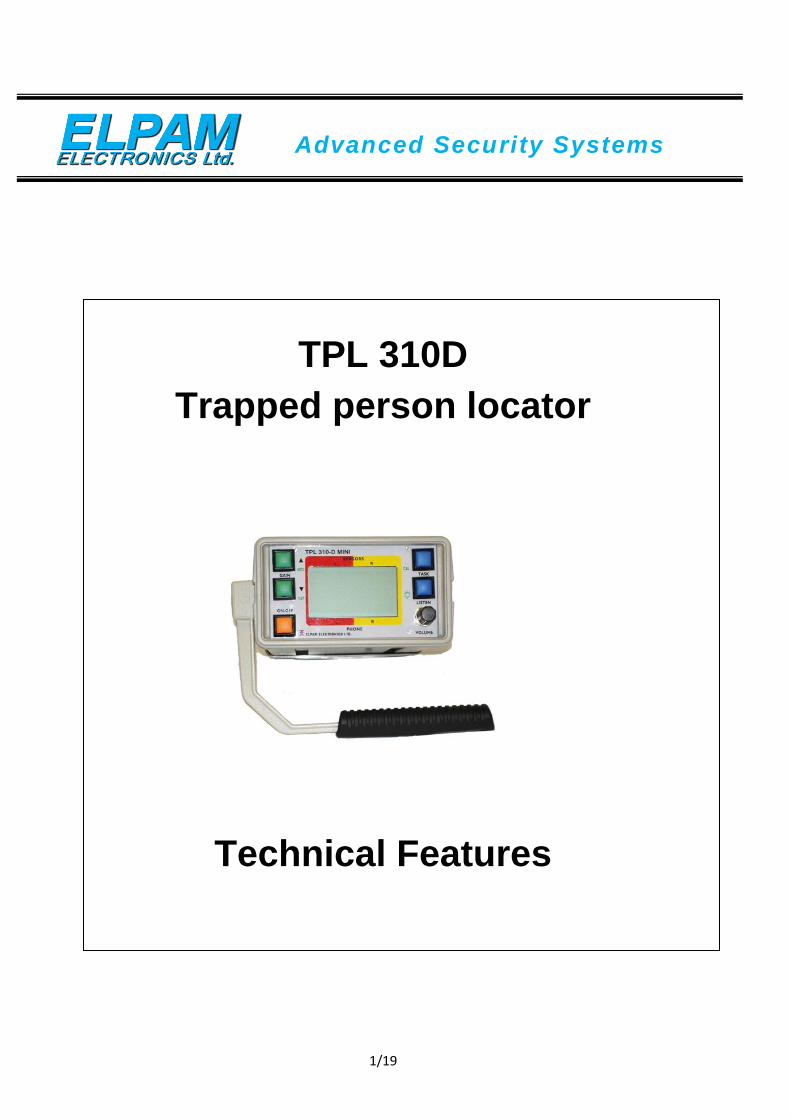
TPL 310D Trapped person locator
Technical Features
2/19
TABLE OF CONTENTS
1. Preface ...………………………………………… …...3
2. Introduction & Technical Features ………………… ..5
3. Operation test ..…………………....………… ……….10
4. Operation for search & Location .………………….…..11
5. Troubleshooting chart .…………………....…………...14
6. System components ………………....………………...15
7. Assembly of TPL.…………………....………………...16
8. Electronic Connection Diagram...……... …..………….17
9. Storage instructions.……... …..…………………....…..18
3/19
1. Preface
1.1 The TPL 310D Series is a new extremely efficient rescue tool, using leading
edge technology. It is based on many years of field experience and
successful rescue results obtained with our TPL 310 A,B and C models.
The new system is very compact, is task- oriented and therefore much
easier to be efficiently applied and efficiently operation, even by
operators with very little training.
1.2 Typical applications range from detecting and pinpointing the location of
trapped persons below and above ground, in locations to which there is no
normal access, like collapsed buildings and structures, collapse caused by
natural or manmade disasters.
1.3 It is assumed that the trapped persons are alive and are able to provide a
minimal response to calls or knockings.
1.4 The new system has a very high sensitivity and a low noise figure, thereby
considerably improving the chances of detecting survivor-generated signals.
1.5 The system’s task oriented design provides two basic tasks, which are:
“SURVEY” and “LOCATE”.
1.6 The “SURVEY” mode of operation, which should be used on the first
approach to most rescue sites, should establish, if any living and conscious
survivors are under the rubble. The system also provides means to
communicate with these trapped persons. The acoustic sensor functions as a
loudspeaker/ microphone, which can be inserted into crevices and allows to
call and listen to the trapped persons.
1.7 The “LOCATE” mode should be established once some kind of
communication has been made with the trapped persons. It serves to provide
information about the location of the person, in or below the rescue site, so
as to guide the rescue team to this location.
1.8 The system has a LCD display, which graphically shows all essential
indications, and guides the operator through the above-mentioned tasks.
For night time operation backlighting is available.

4/19
1.9 With the selection of each task, optimum signal filtering is automatically
performed for each mode of operation, i.e. seismic and/ or acoustic
listening, thereby assuring optimum signal detection capabilities.
1.10 High Sensitive Geophone for seismic detection.
1.11 The system provides manual and automatic gain adjustments. The automatic
gain adjustment is a unique feature, which enables detection of trapped
person signals in high man-made noise.
1.12 The above new features, and others, have been made possible by the design
of the system around a modern microprocessor, which serves as a central
controller of the system.
1.13 The instrument is very compact (approx. 6.0x3.24x7.92 inches or 15x8x20
cm), it holds eight alkaline AA cells, which provide 50 hours of operation
(or with backlighting switched on 25 hours). It can also be operated from an
external 12 Volt battery.
1.14 Two analog output signals are provided for recording of seismic signals by
external strip chart recorder, printer, data logger or tape recorder.
(not included).
1.15 The system is designed to be operated in rain and harsh weather conditions
and will not be affected by nearby mobile transmitters.
5/19
2. Introduction & Technical Features
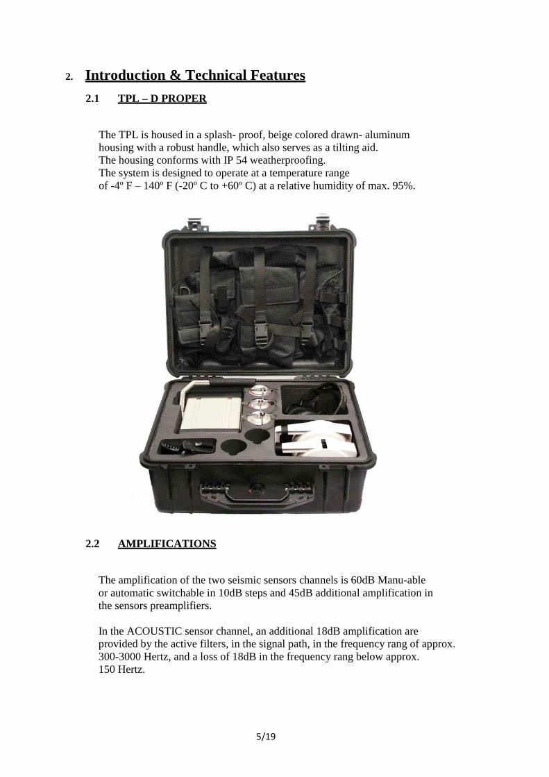
2.1 TPL – D PROPER
The TPL is housed in a splash- proof, beige colored drawn- aluminum
housing with a robust handle, which also serves as a tilting aid.
The housing conforms with IP 54 weatherproofing.
The system is designed to operate at a temperature range
of -4º F – 140º F (-20º C to +60º C) at a relative humidity of max. 95%.
2.2 AMPLIFICATIONS
The amplification of the two seismic sensors channels is 60dB Manu-able
or automatic switchable in 10dB steps and 45dB additional amplification in
the sensors preamplifiers.
In the ACOUSTIC sensor channel, an additional 18dB amplification are
provided by the active filters, in the signal path, in the frequency rang of approx.
300-3000 Hertz, and a loss of 18dB in the frequency rang below approx.
150 Hertz.

6/19
In the SEISMIC sensors channels an additional 18dB amplification are provided
by the active filters, in the frequency band of approx. 150-1000 Hertz, and loss
of 18dB in the frequency band above approx. 1800-3000 Hertz.
The intercom microphone amplifier provides a SPL from the acoustic sensor
of 70dB measured at a distance of 1 meter.
The listening amplifier gains are controlled by a front panel volume control in
the headphones and provide an additional maximum voltage gain of 10dB.
2.3 INPUT/ OUTPUT IMPEDANCES
The output impedance of the listening amplifier allows to drive one or
two 32Ω headphones.
Sensor channels input impedances: approx. 1KΩ (each).
Left and right channels analog outputs of at least 0.5 volt are provided
on the D type connector (left - pin 5; right - pin 3; GND – pin 1) on the
rear panel of the instrument. The outputs are individually adjustable by
two rotary level controls OUT L and OUT R, on the rear panel. The signals
at these outputs are the analog signals after sensor amplifiers and filtering.
The source impedance at this outputs is ~ 200Ω. The signals are provided for
an external strip- chart recorder, printer or data logger.
7/19
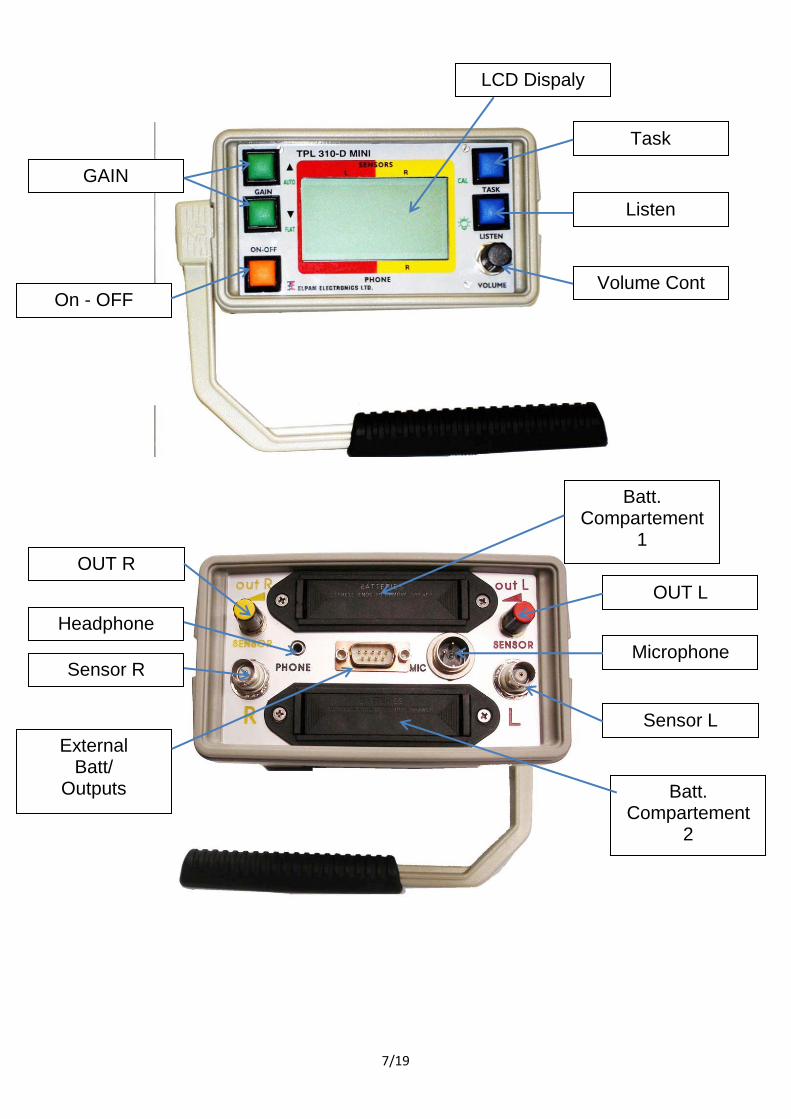
Volume Cont
Listen
Task
LCD Dispaly
GAIN
On - OFF
Batt. Compartement
2
Sensor L
Microphone
OUT L
Batt. Compartement
1 OUT R
Headphone
External Batt/
Outputs
Sensor R
8/19
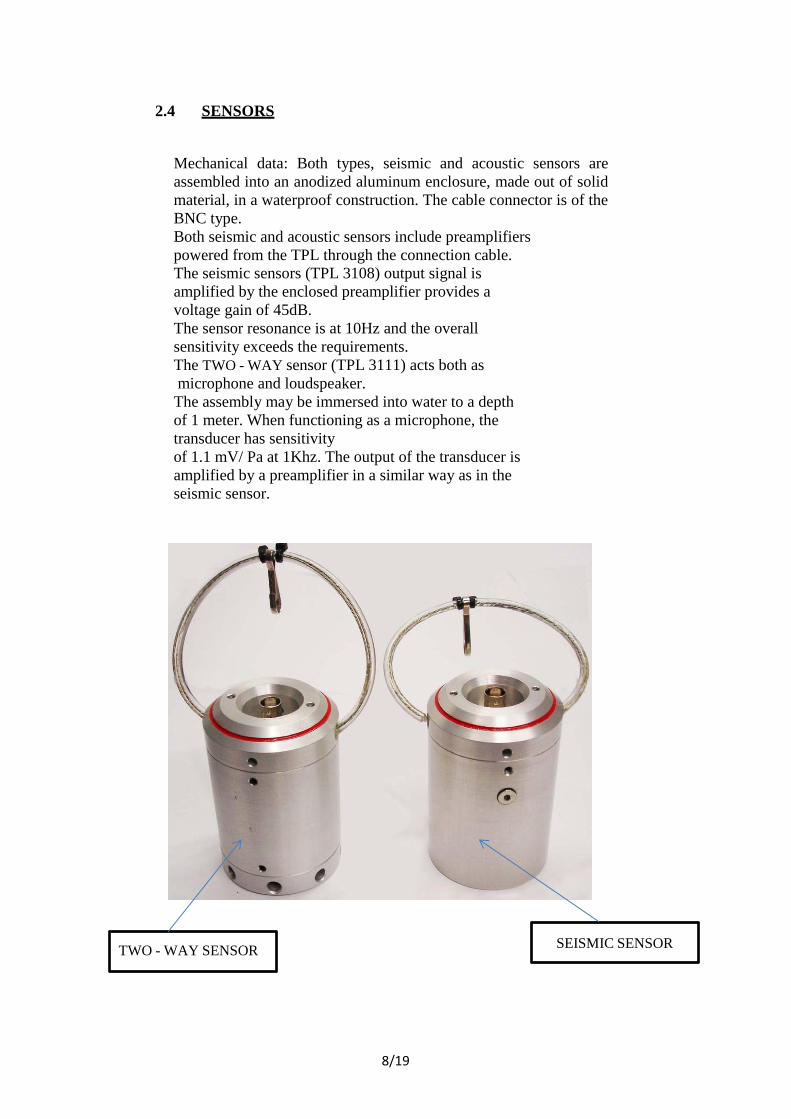
2.4 SENSORS
Mechanical data: Both types, seismic and acoustic sensors are
assembled into an anodized aluminum enclosure, made out of solid
material, in a waterproof construction. The cable connector is of the
BNC type.
Both seismic and acoustic sensors include preamplifiers
powered from the TPL through the connection cable.
The seismic sensors (TPL 3108) output signal is
amplified by the enclosed preamplifier provides a
voltage gain of 45dB.
The sensor resonance is at 10Hz and the overall
sensitivity exceeds the requirements.
The TWO - WAY sensor (TPL 3111) acts both as
microphone and loudspeaker.
The assembly may be immersed into water to a depth
of 1 meter. When functioning as a microphone, the
transducer has sensitivity
of 1.1 mV/ Pa at 1Khz. The output of the transducer is
amplified by a preamplifier in a similar way as in the
seismic sensor.
TWO - WAY SENSOR SEISMIC SENSOR
9/19
2.5 CABLE DISPENSERS
The dispensers hold 33 ft. (10 meter) of coaxial, polyethylene insulated
PVC covered, cable type RG 58C/U terminated with male and female
BNC connectors.
2.6 POWER SUPPLY
Power is provided by eight type AA alkaline batteries, held in two
battery holders accessible from the rear of the TPL.
To open the battery holders, press simultaneously on the two side holders in
the arrow direction, (to the center) and pull out the battery holders.
Alternatively power can be supplied to the TPL through a power
cable, connecting an external 12 volt battery to the D type connector.
The Operating voltage of the TPL is 12 volt. It will function properly
from 8.8 volt up to 16 volt. A voltage monitor will indicate the
battery condition.
The current drain with no input signal is ~40 mA. And with
backlighting ~80 mA.
The positive terminal of the external battery should be connected to
pin 9 and the negative terminal to pin 1.
The external 12 volt battery should not be connected to a charger
or a vehicle while the TPL is in use.
The cable is available as an accessory.
10/19
3. Operation Test
3.1 Insure that the TPL has new 8 AA Alkaline batteries in the battery holders.
3.2 Press the ON - OFF push button, the display will show “ON” momentary
and then “SURVEY”.
3.3 Connect TWO WAY sensor to “L” (Red) connector using the 1m. red coax
cable and the fully unspoiled red cable dispenser.
3.4 Connect the Microphone to “MIC” connector.
3.5 Connect the Headphones to “PHONE” jack.
3.6 Put the TWO WAY sensor about 10 meters from the TPL.
3.7 Press the push to talk switch and speak into the microphone,
the TWO WAY sensor should provide a clear signal.
When the push to talk is not pressed, the TWO WAY sensor acts as
a microphone and can be listened to by the headphone.
3.8 Disconnect the red cable dispenser and the 1m. red coax cable
from the TPL.
Disconnect the TWO WAY sensor and roll the cable back into the
cable dispenser.
3.9 Press “TASK” push button. The display will pass to “LOCATE” mode.
3.10 Connect red seismic sensor to “L” (Red) connector using 1m. red coax
cable and red cable dispenser.
3.11 Connect yellow seismic sensor to “R” (right) connector using 1m.
Yellow coax cable and yellow cable dispenser.
3.12 Knock slightly with your finger on the top of the red seismic sensor.
The Knocking will be heard in the left earphone and showing graphically on
the display.
Increase GAIN as necessary.
Insure the option to adjust the volume.
3.13 Repeat Para. 3.12 with the yellow seismic sensor.
3.14 Disconnect the red & yellow cable dispensers, the 1m. red & yellow coax
cables and the red & yellow seismic sensors.
3.15 Press the light push button for a few seconds, the backlight of the display
will operate. Press momentary again on the light push button, the backlight
turns off.
3.16 Turn the TPL to OFF position by pressing the ON/ OFF push button.
11/19
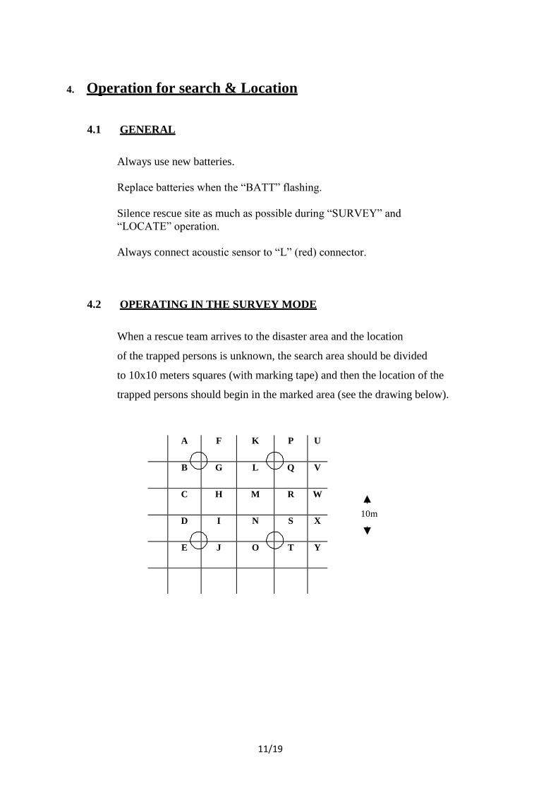
A F K P U
B G L Q V
C H M R W
D I N S X
E J O T Y
4. Operation for search & Location
4.1 GENERAL
Always use new batteries.
Replace batteries when the “BATT” flashing.
Silence rescue site as much as possible during “SURVEY” and
“LOCATE” operation.
Always connect acoustic sensor to “L” (red) connector.
4.2 OPERATING IN THE SURVEY MODE
When a rescue team arrives to the disaster area and the location
of the trapped persons is unknown, the search area should be divided
to 10x10 meters squares (with marking tape) and then the location of the
trapped persons should begin in the marked area (see the drawing below).
10m
12/19
Connect the TWO WAY sensor to “L” (red) connector using the red lm.
coax cable and fully unspoiled cable dispenser.
Connect the SEISMIC sensor to “R” (yellow) connector using the
yellow 1m. coax cable and yellow unspoiled cable dispenser.
Push “ON - OFF” push button to operate the TPL (the display will
indicate “ON” momentary and then “SURVEY”).
Lower the TWO WAY sensor into crevices in the collapsed structure,
call with hand held microphone and listen for replies from the
trapped persons. At the same time, place or attatch the
SEISMIC sensor to vertical beams of collapsed structure, hit the
structure with a metal rod and listen with the headphones to response by
the trapped persons in both SEISMIC and ACOUSTIC sensors.
Adjust sensitivity with GAIN and push buttons. For more
intensive listening to only one of the sensors, repeatedly press LISTEN
push button, display arrows will indicate which sensor is listened too.
Listening volume is controllable by both GAIN and VOLUME control.
When a response is heared in the acoustic sensor, move the SEISMIC
sensor location until the trapped persons tapping response is heard with
the SEISMIC sensor too. Leave the SEISMIC sensor stationary at
this location, increase GAIN until the knocking can be observed on
the display.
Proceed to the LOCATE mode by pushing the task push button.
13/19
4.3 OPERATING IN THE LOCATE MODE
The LOCATE mode should find the location of trapped person or persons
to direct their rescue by comparing the signals amplitude of both sensors.
Replace the ACOUSTIC sensor connected to the “L” with a second
SEISMIC (red) sensor (as indicated on the display), place or attach the
Sensor to an adjacent beams.
Increase GAIN until the tapping signal (by the trapped persons) of
the “R” sensor are also heard and with GAIN adjustment, also seen in
the display.
Move the red SEISMIC sensor (connected to “L”) to beams around the
stationary sensor until a visible indication is also obtained from both sensors.
Signals of equal strength or are within two divisions one from the other,
indicate the trapped person is below the middle between the two sensors.
Other location strategies can also be used.
4.4 REMARKS
4.4.1 At nightfall light push button should be pressed.
4.4.2 The TPL has an automatic gain control. This option enables automatic
adjustment of the needed amplification and also location in noisy
environment.
4.4.3 The maximum signal of each channel is memorized on the display for a
few seconds.
14/19
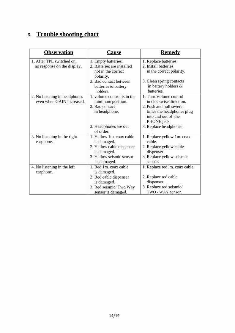
5. Trouble shooting chart
Observation Cause Remedy
1. After TPL switched on,
no response on the display. 1. Empty batteries.
2. Batteries are installed
not in the correct
polarity.
3. Bad contact between
batteries & battery
holders.
1. Replace batteries.
2. Install batteries in the correct polarity.
3. Clean spring contacts
in battery holders &
batteries.
2. No listening in headphones
even when GAIN increased. 1. volume control is in the
minimum position.
2. Bad contact in headphone.
3. Headphones are out
of order.
1. Turn Volume control
in clockwise direction.
2. Push and pull several times the headphones plug
into and out of the
PHONE jack.
3. Replace headphones.
3. No listening in the right earphone.
1. Yellow 1m. coax cable is damaged.
2. Yellow cable dispenser
is damaged.
3. Yellow seismic sensor
is damaged.
1. Replace yellow 1m. coax cable.
2. Replace yellow cable
dispenser.
3. Replace yellow seismic
sensor. 4. No listening in the left
earphone. 1. Red 1m. coax cable
is damaged.
2. Red cable dispenser
is damaged.
3. Red seismic/ Two Way
sensor is damaged.
1. Replace red lm. coax cable.
2. Replace red cable
dispenser.
3. Replace red seismic/
TWO - WAY sensor.
15/19
6. System Components
TPL D SYSTEM
COMPONENTS
PART NUMBER DIMENSIONS (mm) &
WEIGHT (gram/ Kg)
DIMENSIONS (ft) &
WEIGHT (lbs)
QTY
TPL 310D &
ACCESSORIES
TPL D/AC 527 X 219 X 438 mm 11.5 Kg
20 ¾ ” X 8 5/8” X 17 ¼” 33 lbs
1
TPL 310D proper
(With batteries)
TPL D/EU 1.55.5 X 85.5 X 227 mm 1.85 Kg
6.12” X 3.36” X 8.93” 3.85 lbs
1
Seismic sensor red
(Geophone)
TPL 3108A/ 1 60 X 91 mm 615 gram
2.36” X 3.58” 1.35 lbs
1
Seismic sensor yellow
(Geophone)
TPL 3108A/ 2 60 X 91 mm 615 gram
2.36” X 3.58” 1.35 lbs
1
TWO - WAY sensor
microphone/ speaker
TPL 3111 60 X 91 mm 470 gram
2.36” X 3.58” 1.03 lbs
1
Cable dispenser with 33 ft
(10m) long
RED: 118A/ 1
YELLOW: 118A/ 2
139 X 70.5 mm 667 gram
5.47” X 2.78” 1.46 lbs
2
Interconnection cable 3.3 ft
(1m) long
RED: TPL 8
YELLOW: TPL 9
1 meter 58 gram
3.3 ft 0.13 lbs
2
External battery cable 7 ft
(2m) long
TPL 6A 2 meter 110 gram
7 ft 0.28 lbs
1
Microphone hand held TPL D / M 66 X 86 X 38.5 mm 195 gram
2.6” X 3.4” X 1.5” 0.35 lbs
1
Headphones TPL D / HP 200 gram 0.44 lbs 1
Vest for carrying TPL D
accessories
TPL D / VA 650 gram 1.32 lbs 1
Black carrying case TPL/ CC 527 X 219 X 438 mm 5.2 Kg
20 3/4” X 8 5/8” X 17 ¼” 9.89 lbs
1
16/19
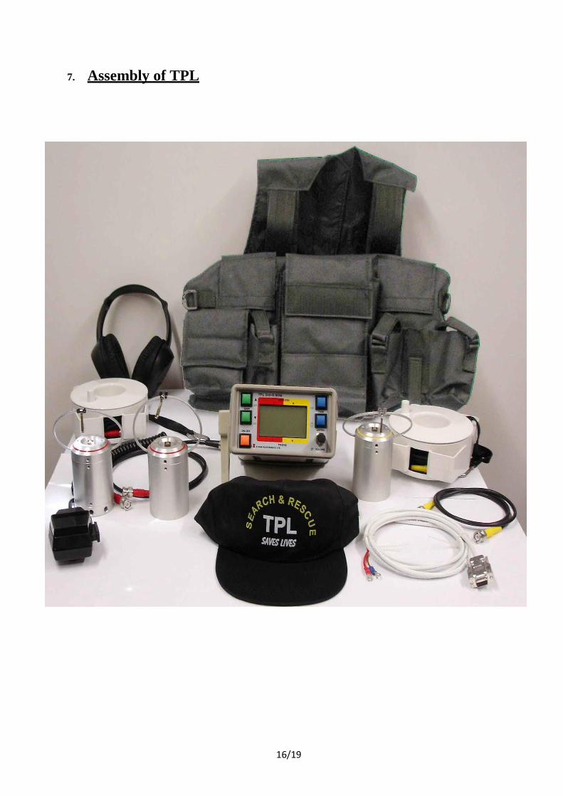
7. Assembly of TPL

17/19
8. Electronic Connection Diagram
T.B.D

18/19
9. Storage Instructions
9.1 Remove batteries before storing the TPL.
9.2 Store the TPL in a dry place.
9.3 Test the stored TPL every 6 months and after each use.
9.4 Clean cables and connectors and perform visual inspection after every use.

19/19
17
The specifications are subject to change without notice.
Advanced Security Systems
Cat. No. M-310D -06/05