towards practical implementation of phase-sensitive...
TRANSCRIPT

thesis for the degree of licentiate of engineering
Towards Practical Implementation of
Phase-Sensitive Amplifier Based Transmission
Systems
Samuel L. I. Olsson
Photonics LaboratoryDepartment of Microtechnology and Nanoscience - MC2
chalmers university of technologyGoteborg, Sweden, 2013
Towards Practical Implementation of Phase-Sensitive
Amplifier Based Transmission Systems
Samuel L. I. Olsson
Goteborg, August 2013
c©Samuel L. I. Olsson, 2013
Chalmers University of TechnologyDepartment of Microtechnology and Nanoscience - MC2Photonics LaboratorySE-412 96 Goteborg, SwedenPhone: +46 (0) 31 772 1000
ISSN 1652-0769Technical Report MC2 - 260
Printed by Bibliotekets reproservice, Chalmers University of TechnologyGoteborg, Sweden, August, 2013

Towards Practical Implementation of
Phase-Sensitive Amplifier Based Transmission
Systems
Samuel L. I. Olsson
Photonics LaboratoryDepartment of Microtechnology and Nanoscience - MC2
Chalmers University of Technology, SE-412 96 Goteborg, Sweden
AbstractAll commercially available optical amplifiers are so-called phase-insensitive ampli-fiers (PIAs) which degrade the signal-to-noise ratio (SNR) through the amplifica-tion process. This kind of amplifier has a quantum limited noise figure (NF) of 3dB. Another category of amplifiers are phase-sensitive amplifiers (PSAs) which intheory are capable of noiseless amplification, i.e. amplification with a 0 dB NF.Successful implementation of PSAs in transmission systems would lead to signifi-cant performance improvements compared to using conventional PIAs. However,the implementation is challenging and no system with wavelength division multi-plexing (WDM) compatibility has previously been demonstrated over a significanttransmission distance.
This thesis is dedicated to realizing and investigating the properties of PSA-amplified transmission links utilizing fiber optical parametric amplifiers (FOPA)and the so-called copier-PSA scheme. One of the main challenges on the waytowards realization is to recover and amplify a weak phase-modulated wave withhigh fidelity. To handle this, a hybrid injection locking (IL)/Erbium-doped fiberamplifier (EDFA)-based pump recovery system was designed and thoroughly in-vestigated experimentally. Other challenges include continuous phase-locking ofseveral waves and high-precision wave tuning.
A single-span PSA-amplified transmission link with WDM compatibility wasdemonstrated over 80 km of fiber. The link performance was compared against aconventional EDFA-based link for operation both in the linear and nonlinear trans-mission regime. The PSA-amplified system is shown to have capability to mitigatenonlinear distortions due to the Kerr effect and outperform the EDFA-amplifiedlink in both regimes.
Keywords: fiber nonlinearities, fiber optic parametric amplification, four-wavemixing, nonlinear optical signal processing, optical injection locking, phase-sensitiveamplification
i

ii

List of papers
Appended publications
This thesis is based on work contained in the following papers:
[A] S. L. I. Olsson, B. Corcoran, C. Lundstrom, E. Tipsuwannakul, S. Sygletos,A. D. Ellis, Z. Tong, M. Karlsson, and P. A. Andrekson “Injection locking-based pump recovery for phase-sensitive amplified links,” Optics Express 21,14512–14529 (2013).
[B] B. Corcoran, S. L. I. Olsson, C. Lundstrom, M. Karlsson, and P. Andrek-son, “Phase-sensitive Optical Pre-Amplifier Implemented in an 80km DQPSKLink,” in Optical Fiber Communication Conference and Exposition (OFC)and National Fiber Optic Engineers Conference (NFOEC), Technical Digest(CD) (Optical Society of America, 2012), Post-deadline paper PDP5A.4.
[C] S. L. I. Olsson, B. Corcoran, C. Lundstrom, M. Sjodin, M. Karlsson, andP. A. Andrekson, “Phase-Sensitive Amplified Optical Link Operating in theNonlinear Transmission Regime,” in European Conference and Exhibition onOptical Communication (ECOC), Technical Digest (CD) (Optical Society ofAmerica, 2012), paper Th.2.F.1.
iii

Other publications
The following papers has been published or been accepted for publication but arenot included in the thesis. The content partially overlap with the appended papersor is out of the scope of this thesis.
[D] S. L. I. Olsson, B. Corcoran, C. Lundstrom, E. Tipsuwannakul, S. Sygletos,A. D. Ellis, Z. Tong, M. Karlsson, and P. A. Andrekson “Optical Injection-Locking-Based Pump Recovery for Phase-Sensitively Amplified Links,” inOptical Fiber Communication Conference and Exposition (OFC) and Na-tional Fiber Optic Engineers Conference (NFOEC), Technical Digest (CD)(Optical Society of America, 2012), paper OW3C.3.
[E] C. Lundstrom, B. Corcoran, S. L. I. Olsson, Z. Tong, M. Karlsson, and P.A. Andrekson, “Short-Pulse Amplification in a Phase-Sensitive Amplifier,”in Optical Fiber Communication Conference and Exposition (OFC) and Na-tional Fiber Optic Engineers Conference (NFOEC), Technical Digest (CD)(Optical Society of America, 2012), paper OTh1C.1.
[F] T. Richter, B. Corcoran, S. L. I. Olsson, C. Lundstrom, M. Karlsson, C.Schubert, and P. A. Andrekson, “Experimental Characterization of a Phase-Sensitive Four-Mode Fiber-Optic Parametric Amplifier,” in European Con-ference and Exhibition on Optical Communication (ECOC), Technical Digest(CD) (Optical Society of America, 2012), paper Th.1.F.1.
[G] L. Gruner-Nielsen, D. Jakobsen, S. Herstrøm, B. Palsdottir, S. Dasgupta, D.Richardson, C. Lundstrom, S. L. I. Olsson, and P. A. Andrekson, “BrillouinSuppressed Highly Nonlinear Fibers,” in European Conference and Exhibitionon Optical Communication (ECOC), Technical Digest (CD) (Optical Societyof America, 2012), paper We.1.F.1.
[H] C. Lundstrom, R. Malik, L. Gruner-Nielsen, B. Corcoran, S. L. I. Olsson, M.Karlsson, and P. A. Andrekson, “Fiber Optic Parametric Amplifier With 10-dB Net Gain Without Pump Dithering,” IEEE Photonics Technology Letters25, 234-237 (2013).
[I] C. Lundstrom, S. L. I. Olsson, B. Corcoran, M. Karlsson, and P. A. An-drekson, “Phase-Sensitive Amplifiers for Optical Links,” in Optical FiberCommunication Conference and Exposition (OFC) and National Fiber OpticEngineers Conference (NFOEC), Technical Digest (CD) (Optical Society ofAmerica, 2013), paper OW3C.5.
[J] B. Corcoran, S. L. I. Olsson, C. Lundstrom, M. Karlsson, and P. A. An-drekson, “Mitigation of Nonlinear Impairments on QPSK Data in Phase-Sensitive Amplified Links,” Accepted to European Conference and Exhibitionon Optical Communication (ECOC), Technical Digest (CD) (Optical Societyof America, 2013)
[K] C. Lundstrom, R. Malik, A. L. Riesgo, B. Corcoran, S. L. I. Olsson, M.Karlsson, and P. A. Andrekson, “Fiber-optic Parametric Amplifiers WithoutPump Dithering,” Accepted to 3rd Workshop on Specialty Optical Fiber andTheir Applications, 2013
iv

Acknowledgement
First and foremost I would like to thank my supervisors Peter Andrekson andMagnus Karlsson for accepting me as a PhD student, their guidance and support,and for being good role models. Bill Corcoran deserves special thanks for goodcollaboration and his contributions to the publications in this thesis. It has beena pleasure working with such a skilled, efficient, and enthusiastic person. I willalways remember our intense work together in the lab before the deadlines.
Carl Lundstrom also deserves special thanks for helping to solve many of theeveryday issues, sharing his expertise and knowledge, and for his contributions tothe papers. I am very grateful to Tong Zhi for always taking time to answer myquestions and for being a good source of inspiration through the impressive workhe carried out while he was working at the photonics laboratory.
Ekawit Tipsuwannakul and Pontus Johannisson should be thanked for sharingtheir expertise and always being willing to help. Martin Wahlsten deserves thanksfor giving me a good introduction when I just started my PhD studies, coming tothe laboratory without any prior knowledge of fiber optics.
I would like to express my gratitude to Andrew Ellis for letting me spend timeat Tyndall National Institute in Cork, Ireland and Stylianos Sygletos for teachingme about phase-locked loops and injection locking during the visit. When workinglong hours it is important to fit in some breaks. The number one break activityhas been to play ping pong and I want to thank, especially Martin Sjodin, but alsoTobias Eriksson and Yuxin Song for many great ping pong games.
I would also like to thank the whole photonics laboratory and visiting re-searches that have been in the group for creating a nice working environment.
Last but not least, I would like to thank my family and friends.
Samuel L. I. Olsson
GoteborgAugust 2013
v

This work was financially supported by the European Commission STREPProject PHASORS (FP7-ICT-2007-2 22457), the European Research Council Ad-vanced Grant PSOPA (291618), the Knut and Alice Wallenberg Foundation, andalso by the Swedish Research Council (VR).
vi

List of Acronyms
16QAM 16-ary quadrature amplitude modulation 7, 45
AOM acousto-optic modulator 34
AQN amplified quantum noise 25
ASE amplified spontaneous emission 8, 10, 25, 32, 43
BER bit error ratio 47
CD chromatic dispersion 5
CW continuous wave 20, 31, 32
DFA doped fiber amplifier 7, 8
DFB distributed feedback 42
DQPSK differential quadrature phase-shift keying 37, 47
DSP digital signal processing 38
EDFA erbium-doped fiber amplifier 1, 3–5, 7–10, 20, 21, 31, 32, 37, 38, 45, 47,48
FEC forward error correction 2
FOPA fiber optical parametric amplifier 3, 4, 7, 19–21, 23, 24, 27, 31, 38
FWM four-wave mixing 3, 19–25, 31, 32
HDTV high-definition television 2
HNLF highly nonlinear fiber 31, 32
ICT information and communication technology 1, 2
IL injection locking 41, 42, 47
ML master laser 42, 43
NF noise figure 3, 5, 8–10, 12–17, 19, 21, 28, 30, 31, 35–37, 47
OIL optical injection locking 4, 38, 41–43
vii

OOK on-off keying 7
OPC optical phase conjugation 38
OSNR optical signal-to-noise ratio 6
PC polarization controller 32
PI phase-insensitive 3, 15–17, 19, 20, 24, 28, 29, 33–36
PI-FOPA phase-insensitive fiber optical parametric amplifier 21, 32
PIA phase-insensitive amplifier 3, 5–8, 14–16, 28, 30, 33, 35–37
PLL phase-locked loop 39
PM-QPSK polarization-multiplexed quadrature phase-shift keying 7
PMD polarization-mode dispersion 5
PS phase-sensitive 3, 16, 17, 19, 20, 24, 28–30, 33–36
PS-FOPA phase-sensitive fiber optical parametric amplifier 3, 4, 19, 21
PSA phase-sensitive amplifier 3–5, 7, 15–17, 28, 30, 33–39, 41, 45, 47, 48
RF radio frequency 12, 47
RIN relative intensity noise 42
SBS stimulated Brillouin scattering 31, 32, 45
SHG second harmonic generation 20
SL slave laser 42, 43
SNR signal-to-noise ratio 2, 3, 5, 12, 13, 30, 37, 48
SOA semiconductor optical amplifier 7, 9, 10
SOP state of polarization 39, 42
SPM self-phase modulation 6, 22, 23, 38
SRS stimulated Raman scattering 10, 31
SSMF standard single mode fiber 9, 22, 31
VOA variable optical attenuator 43
WDM wavelength division multiplexing 2, 4, 6–10, 32–35, 37, 39, 45
XPM cross-phase modulation 6, 22, 23, 38
ZDW zero-dispersion wavelength 20, 31
viii

Contents
Abstract i
List of papers iii
Acknowledgement v
Acronyms vii
1 Introduction 11.1 Background . . . . . . . . . . . . . . . . . . . . . . . . . . . . . . . 21.2 Motivation . . . . . . . . . . . . . . . . . . . . . . . . . . . . . . . 41.3 Thesis outline . . . . . . . . . . . . . . . . . . . . . . . . . . . . . . 4
2 Amplification and noise limits 52.1 Optical amplification . . . . . . . . . . . . . . . . . . . . . . . . . . 5
2.1.1 Introduction . . . . . . . . . . . . . . . . . . . . . . . . . . 52.1.2 Amplifier noise . . . . . . . . . . . . . . . . . . . . . . . . . 62.1.3 System requirements . . . . . . . . . . . . . . . . . . . . . . 72.1.4 Amplification techniques . . . . . . . . . . . . . . . . . . . . 8
2.2 Quantum noise limits . . . . . . . . . . . . . . . . . . . . . . . . . 112.2.1 Fundamental concepts . . . . . . . . . . . . . . . . . . . . . 112.2.2 Phase-insensitive amplifiers . . . . . . . . . . . . . . . . . . 142.2.3 Phase-sensitive amplifiers . . . . . . . . . . . . . . . . . . . 15
2.3 Noise in multi-span links . . . . . . . . . . . . . . . . . . . . . . . . 16
3 Fiber optical parametric amplifiers 193.1 Introduction . . . . . . . . . . . . . . . . . . . . . . . . . . . . . . . 193.2 Four-wave mixing . . . . . . . . . . . . . . . . . . . . . . . . . . . . 21
3.2.1 Phase-matching . . . . . . . . . . . . . . . . . . . . . . . . . 233.3 Parametric amplification . . . . . . . . . . . . . . . . . . . . . . . . 243.4 Transfer matrix description . . . . . . . . . . . . . . . . . . . . . . 25
3.4.1 Phase-insensitive mode . . . . . . . . . . . . . . . . . . . . 283.4.2 Phase-sensitive mode . . . . . . . . . . . . . . . . . . . . . . 28
ix

3.5 Design and implementation . . . . . . . . . . . . . . . . . . . . . . 31
4 Phase-sensitively amplified links 334.1 Introduction . . . . . . . . . . . . . . . . . . . . . . . . . . . . . . . 344.2 Link architectures . . . . . . . . . . . . . . . . . . . . . . . . . . . 35
4.2.1 The copier-PSA scheme . . . . . . . . . . . . . . . . . . . . 354.3 Nonlinear distortion mitigation . . . . . . . . . . . . . . . . . . . . 384.4 Implementation challenges . . . . . . . . . . . . . . . . . . . . . . . 38
5 Optical injection locking 415.1 Introduction . . . . . . . . . . . . . . . . . . . . . . . . . . . . . . . 415.2 Basic concepts . . . . . . . . . . . . . . . . . . . . . . . . . . . . . 42
5.2.1 Experimental implementation . . . . . . . . . . . . . . . . . 425.2.2 Injection ratio . . . . . . . . . . . . . . . . . . . . . . . . . 425.2.3 Locking bandwidth . . . . . . . . . . . . . . . . . . . . . . . 435.2.4 Theoretical explanation models . . . . . . . . . . . . . . . . 43
6 Outlook 45
7 Summary of papers 47
References 49
Appendix 57
A Derivations 57A.1 Derivation of B+(A+) and B−(A−) . . . . . . . . . . . . . . . . . . 57A.2 Derivation of B+(Ar,+) and B−(Ar,−) . . . . . . . . . . . . . . . . 58
Papers A-C 59
x

Chapter 1
Introduction
From the beginning of mankind inventions and technical advances have driven ourdevelopment and formed the world we live in. Today’s society is to a large extentshaped by the information and communication technology (ICT) that emerged inthe 1990’s. The ICT has had a profound impact on everyday life, for instancethrough enabling services that make information more accessible and providingnew means for communication and media consumption. The ICT has also con-tributed to large scale trends such as globalization by making distance less of aboundary. Based on the global interest in ICT related services it is most likelythat what we have seen so far is only the beginning of the ICT era.
The key enabling technology for the ICT was the long-haul fiber optical com-munication system, making it possible to transmit information at high speed overintercontinental distances. The long-haul fiber optical communication system wasin turn realized based on a number of inventions and technical advances of the lastcentury. The most important components were the laser [1], the low-loss opticalfiber [2], and the erbium-doped fiber amplifier (EDFA) [3]. If the ICT can con-tinue to develop, depends to a large extent on today’s innovations and technicaladvances.
The main topic of this thesis concern a novel optical amplification system thatcan potentially improve the performance of long-haul fiber optical communicationsystems and through this lead to continued development in the area of ICT.
Chapter outline
In section 1.1 we place this work in a context and give a motivation to why thework is of interest to the general community. In section 1.2 the motivation foreach appended paper is described in detail. Finally, in section 1.3 we outline thestructure and content of the thesis.
1

1.1 Background
The development of services in the area of ICT goes hand in hand with an increaseddemand for capacity in the fiber optical communication systems. Particularlycapacity intensive services are those in the field of home entertainment, where rapidadvancements in display technology and technical solutions for distribution overinternet push the demand. New standards, where current examples are ultra high-definition television (HDTV), with up to sixteen times the pixel count of standardHDTV, and 3D television, will increase the demand for capacity. Another fieldis business and productivity related services where e.g. cloud computing, cloudstorage, and virtual meetings will contribute to an increased demand. Additionally,the number of people and devices connected to internet is expected to grow whichwill also add to the demand.
The current state-of-the-art long-haul fiber optical transmission systems are theresult of four decades of development and technological advances. One of the firstcommercial systems, deployed in 1977, operated at 45 Mb/s over a distance of 2.6km [4]. This should be compared to current state-of-the-art field experiments weredata is transmitted at 40.5 Tb/s over 1 822 km [5]. This capacity increase of almostsix orders of magnitude and considerable reach extension has been accomplishedby implementing techniques such as wavelength division multiplexing (WDM),i.e. simultaneously transmitting information at several wavelengths, forward errorcorrection (FEC), and advanced modulation formats [6]. Although the technologyhas progressed the basic building blocks of a long-haul fiber optical transmissionsystem are still the same.
A long-haul fiber optical communication system consists of a transmitter, op-tical fiber spans, and a receiver. The function of the transmitter is to generate anoptical signal encoded with the data that should be transmitted. The optical fiberguide the light between the origin and the destination. Despite the extremely lowattenuation that can be achieved in optical fibers, with the current record being0.149 dB/km [7], periodic amplification is needed to compensate for the attenua-tion. The receiver finally detect the transmitted signal and recover the data.
The capacity (bit/s) of a communication system can be defined as the productof the spectral efficiency (bit/s/Hz), a measure of how efficient the spectrum isused, and the signal bandwidth (Hz). In general terms the capacity can be in-creased if the signal-to-noise ratio (SNR) at the receiver is increased [8]. HigherSNR at the receiver can e.g. enable usage of modulation formats with higherspectral efficiency.
The SNR at the receiver in a long-haul fiber optical communication system canbe increased by boosting the signal power at the output of the transmitter or byreducing the noise added by the optical amplifiers. The latter can be done eitherby improving the noise performance of the individual amplifies or by reducing thespacing between the amplifiers, thus increasing the total number of amplifiers.Increasing the number of amplifiers is in general not preferred due to higher cost
2

and focus is instead on improved noise performance.The noise added to a signal by an optical amplifier is quantified by the amplifier
noise figure (NF), defined as the ratio of the input SNR to the output SNR.All commercial optical amplifiers available today are so-called phase-insensitiveamplifiers (PIAs), meaning that the gain is independent of the signal phase. Thiskind of amplifier has a 3 dB quantum-limited NF at high gain [9]. In currentlong-haul fiber optical communication systems the most commonly used amplifieris the EDFA, a PIA. The lowest NF that has been experimentally demonstratedfor an EDFA is 3.1 dB [10].
Another class of amplifiers are phase-sensitive amplifiers (PSAs), for which thegain is dependent on the signal phase. The quantum-limited NF for this kind ofamplifier is 0 dB [11], which in practice mean noiseless amplification. Successfulimplementation of a low NF amplifier in a long-haul fiber optical communicationsystem would have major implications due to the large reduction in SNR degra-dation through the transmission link. The improvement in SNR could either beused for increasing the capacity or extending the reach.
As mentioned earlier there are several techniques implemented in today’s long-haul fiber optical communication systems for increasing capacity. Some of thesetechniques place requirements on the optical amplifiers in the link. It is, e.g.,crucial that the amplifiers are able to amplify several wavelength channels simul-taneously over a wide bandwidth and in the range where the optical fiber haslow loss, that they are modulation format, symbol rate, and polarization inde-pendent, as well as capable of low-noise, high-gain, and flat-gain operation, withhigh gain efficiency. The EDFA is the amplification technology that best satisfythese requirements and thus has become widely used. However, the EDFA is notthe perfect amplification technology. For example, the bandwidth of EDFAs isfairly limited and the SNR will always be degraded by at least 3 dB. The problemwith limited bandwidth has to some extent been solved by combining EDFAs withRaman amplifiers in hybrid amplification systems [12,13].
Fiber optical parametric amplifiers (FOPAs) can be operated in both phase-insensitive (PI)- and phase-sensitive (PS)-mode and has proved to be a promisingamplification technology. FOPAs rely on four-wave mixing (FWM) where sev-eral waves interact to provide gain through parametric amplification and are mostnotably capable of high gain, with the current record being 70 dB [14], wide band-width [15], and noiseless amplification when operated in PS-mode. In some aspectsFOPAs show better performance than EDFAs, although from a practical point ofview, also taking cost into consideration, EDFAs are still the most attractive op-tical amplification technology.
Phase-sensitive fiber optical parametric amplifiers (PS-FOPAs) can be eitherfrequency-degenerate or frequency-nondegenerate depending on how the wave-lengths of the interacting waves are chosen. Frequency-nondegenerate PS-FOPAsare capable of simultaneous amplification of many wavelength channels but havehistorically been difficult to implement due to strict requirements on phase-locking
3

of the interacting waves. In 2005 the so-called copier-PSA scheme was proposedand provided a satisfactory solution to the problem of phase-locking the waves [16].This scheme made it possible to design multi-channel, modulation format indepen-dent [17], PSA-amplified links.
There have been some studies of PS-FOPA-amplified transmission links butnone including both a significant length of transmission fiber and featuring thecapability of modulation format independent operation. Thus, up until now therehave been no convincing demonstrations of PSA-amplified transmission links.
1.2 Motivation
The motivation behind this thesis work has been to demonstrate a modulationformat independent and WDM compatible PSA-amplified transmission link, im-plemented using a PS-FOPA, over a significant length of fiber and with betterperformance than a comparable EDFA-amplified transmission link.
In [Paper A] we take the first step towards realizing a PSA-amplified transmis-sion link by demonstrating a hybrid optical injection locking (OIL)/EDFA-basedpump recovery system, a necessary part of a long span PSA-amplified link. Thesystem we demonstrate is capable of enabling PSA-amplified links with more than200 km long spans. The operating limit of the system is thoroughly investigated.In [Paper B] we use the pump recovery system to demonstrate the longest modu-lation format independent and WDM compatible PSA-amplified transmission linkever reported. We compare the performance to an EDFA-amplified link and showbetter performance for the PSA-amplified link.
From the perspective of capacity, an interesting limit for all transmission sys-tems is the limit of high signal power launched into the fiber span. In [Paper C]we characterize the previously demonstrated PSA-amplified transmission link inthe regime of nonlinear transmission.
1.3 Thesis outline
In chapter 2 we introduce the topic of optical amplification and discuss the noiselimits of optical amplifiers. In chapter 3 we describe FOPAs, the amplificationtechnology that this thesis work is based on, in detail. In chapter 4 the imple-mentation of PSAs in transmission links is discussed along with the properties ofthese links. The scheme for realizing a long span PSA-amplified link rely on OIL.The concept of OIL is briefly introduced in chapter 5. In chapter 6 future topicsof research, building upon what is presented in this thesis, are presented. In thefinal chapter, chapter 7, the appended papers are summarized.
4

Chapter 2
Amplification and noise limits
The maximum attainable capacity in a communication system is related to thesignal SNR before the receiver. In a long-haul fiber optical communication systemthis is mainly governed by the noise properties of the link amplifiers. The increasingdemand for capacity thus makes optical amplifier noise an important topic.
All conventional optical amplifiers, including the very common EDFA, are PIAswith a 3 dB quantum limited NF. PSAs on the other hand have a 0 dB quantumlimited NF, which in practice mean noiseless amplification.
Chapter outline
The purpose of this chapter is to give an introduction to optical amplification andto provide an understanding of the different noise properties in PIAs and PSAs.To this end, in section 2.1 we introduce the topic of optical amplification alongwith the most common amplification techniques. The fundamental limit to thenoise added by an amplifier is determined by quantum mechanics. In section 2.2we discuss the quantum noise limits for PIAs and PSAs. Finally, in section 2.3 wediscuss how amplifier noise impacts the performance in multi-span links.
The material presented in this chapter is essential for understanding the mo-tivation behind the work in [Paper B], where the target was to demonstrate aPSA-amplified link that outperform a conventional EDFA-amplified link.
2.1 Optical amplification
2.1.1 Introduction
Propagating a signal through an optical fiber will unavoidably lead to attenua-tion and distortion of the signal. The distortion can either be due to linear ornonlinear effects occurring in the optical fiber. Linear effects, such as chromaticdispersion (CD) and polarization-mode dispersion (PMD), are independent of the
5

signal power and are always present. These effects are in general easier to mitigatethan nonlinear effects, such as self-phase modulation (SPM) and cross-phase mod-ulation (XPM), which depend on the signal power and manifest at high powers orlong transmission distances.
A communication system relies on that the transmitted data can be accuratelyrecovered at the end of the link. In practice this means that the signal cannot betoo distorted by linear and nonlinear effects and that the power at the receiveris high enough so that the signal can be received without adding excessive noise.The naive solution to satisfy this power condition would be to increase the powerlaunched into the link. However, this would increase the nonlinear distortions ofthe signal and is therefore, in most cases, not a viable path. Instead, the opticalpower has to be managed throughout the link so that the power condition atthe receiver is satisfied without reaching too high signal power and then inducenonlinear distortion at any given point in the link.
From the early years of long-haul fiber optical communication systems up untilthe mid 90’s fiber loss was mostly managed by periodically detecting and retrans-mitting the signal using optoelectronic repeaters. Using repeaters was not a prac-tical solution for loss management in WDM systems since one receiver-transmitterpair is needed for each wavelength channel, resulting in a complex and expensivesystem. With the introduction of WDM an alternative loss management tech-nique was therefore required and optical amplification, capable of simultaneousamplification of many channels, became the mainstream method.
2.1.2 Amplifier noise
Optical amplification is associated with degradation of the signal quality due tonoise added by the amplifier. Without taking the receiver into account the qualityof the signal can be quantified by the optical signal-to-noise ratio (OSNR) measure,specifying the ratio between the signal power and the noise power in a givenbandwidth. Since both the signal and the noise at the input of an amplifier isamplified the OSNR would not degrade if the amplifier did not add any excessnoise. However, in many cases, the amplifier has independent internal noise thatis added to the signal, thus leading to degraded OSNR.
In multi-span transmission links, i.e. links with many cascaded amplifiers,the noise added by the amplifiers accumulate throughout the link and successivelyreduce the OSNR. For a communication system the signal OSNR is strongly relatedto the attainable capacity [18], with higher OSNR enabling higher capacity. Thenoise properties of the amplifiers is therefore very important when designing acommunication system.
Common for all commercially available optical amplifiers is that they are PIAs,i.e. their gain is independent of the signal phase. Moreover, they are generallyoperated in a linear regime, i.e. where the output signal is linearly related to theinput signal. Working in the linear regime is preferred since working in a nonlinear
6

regime would induce signal distortions.The ultimate limit to how much noise is added by an optical amplifier is gov-
erned by quantum mechanics. It has been shown that all PIAs operating in thelinear regime with a gain G > 1 must add noise to the signal since a noise-free am-plifier would violate Heisenberg’s uncertainty principle [19,20]. PSAs on the otherhand, for which the gain is dependent on the signal phase, can in theory amplifya signal without adding any noise [11]. This property of noiseless amplificationmake PSAs very interesting for transmission system applications.
2.1.3 System requirements
In today’s long-haul fiber optical communication systems WDM is one of the mostimportant techniques for increasing capacity. It is thus essential that the opticalamplifiers in the link can provide gain (> 20 dB) over large bandwidths. Further-more, it is important that the gain is flat over the signal bandwidth since gaindifferences between the channels would accumulate into large power differences.
Traditionally on-off keying (OOK) has been the most commonly used modu-lation format in optical communication systems. However, the trend is movingtowards using more advanced modulation formats with higher spectral efficiency,such as polarization-multiplexed quadrature phase-shift keying (PM-QPSK) and16-ary quadrature amplitude modulation (16QAM). This requires the amplifiersto be polarization independent, modulation format independent, and have smallsignal distortion.
As for all systems energy consumption and cost is important. It is thereforeimportant that the amplifier has a high gain efficiency, i.e. low pump powerrequirement per dB of gain. Furthermore, to reduce the energy consumption andcost, a primary concern when designing a communication system is to minimizethe transmission loss. In a fiber optical communication system the loss originatemainly from attenuation in the optical fiber. The loss is wavelength dependentand the range which has the lowest loss is called the conventional ’C’-band andspans from 1530 to 1570 nm in silica fibers. It is thus important that the amplifieris capable of amplification in the C-band.
Several types of optical amplifiers, capable of amplification in the C-band,are commercially available. The most common types are doped fiber amplifiers(DFAs), with the EDFA [21] being the dominating technology, Raman ampli-fiers [22], semiconductor optical amplifiers (SOAs) [23], and FOPAs [15]. Theseamplifiers are based on different gain mechanisms and have different performanceand properties.
7

2.1.4 Amplification techniques
Erbium-doped fiber amplifiers
The EDFA is the dominating technology for loss management in today’s long-rangefiber optical communication systems. The EDFA was invented in 1986 [3], andquickly became an interesting technology due to its capability to amplify signalsin the C-band. After its commercialization in the mid-1990s it rapidly gained itsposition as the leading loss management technology.
The EDFA, with a bandwidth of about 40 nm (5.3 THz), is mainly used forC-band operation but longer ’L’-band (1570-1610 nm) operation has been demon-strated by increasing the erbium concentration [24], and shorter ’S’-band (1490-1520 nm) operation by using a double-pass configuration [25]. DFAs operatingin the S-band (1480-1510 nm) can also be constructed by doping with thuliuminstead of erbium [26].
All DFAs are optically pumped and amplification is achieved through popula-tion inversion, i.e. the majority of the ions are in an excited state, and stimulatedemission. Along with the stimulated emission there is also spontaneous emission.The spontaneously emitted photons will be amplified and result in amplified spon-taneous emission (ASE). The ASE will then beat with the signal at detection andcause noise, which is the main noise source associated with EDFAs.
The amount of ASE noise generated in an EDFA is affected by the pump wave-length and the pumping scheme. Pumping can be done at 980 and 1480 nm, with980 nm pumping giving better noise performance. The pumping schemes com-monly employed are unidirectional pumping in the forward or backward directionand bidirectional pumping.
Apart from the capability of C-band operation, the EDFA has many othervaluable features. The gain mechanism in EDFAs results in a very slow gainresponse time, on the order of milliseconds. This feature makes of possible tooperate EDFAs in gain saturation mode without inducing signal distortion andchannel crosstalk in WDM systems, i.e. they can work as linear amplifiers on abit level even if the gain is saturated on average.
From a long-haul transmission system perspective other important features arepolarization insensitivity and high gain, a high gain efficiency, ∼ 0.1 mW pumppower required per dB of gain [27], and low NF, 3.1 dB at 54 dB gain has beendemonstrated [10]. Its compatibility with silica fibers and low insertion loss is alsoimportant. All these features have contributed to the popularity of the EDFA.
The gain of EDFAs is not dependent on the phase of the signal and EDFAs aretherefore PIAs and have a 3 dB quantum limited NF. The actual NF is stronglydependent on the population inversion, with the lowest NF attainable at the high-est population inversion. In the high gain limit the NF of an EDFA is given byNF = 2nsp where nsp is the spontaneous emission factor which is always greaterthan or equal to unity [9, p. 100]. For complete medium inversion the spontaneousemission factor equals unity and the NF take the value of 2 (3 dB). In practice the
8
SSMFEDFATransmitter Receiver
...
(a) Booster
Transmitter ReceiverEDFASSMF
...
(b) Preamplifier
Transmitter ReceiverEDFASSMF
... ...
SSMF
(c) In-line amplifier
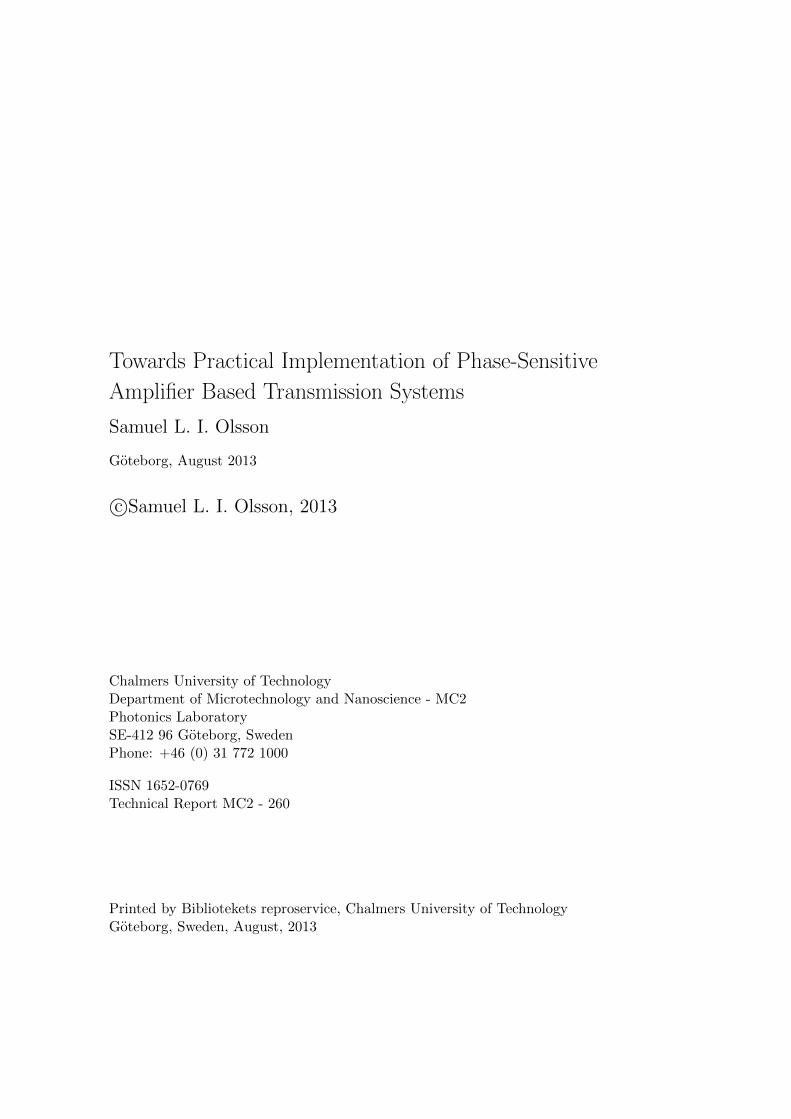
Figure 2.1: Illustration of possible EDFA implementations. SSMF: standard single
mode fiber.
NF exceeds 3 dB and can be as large as 6-8 dB in commercial amplifiers due toother noise sources.
EDFAs, and amplifiers in general, have a few different common usages in fiberoptical communication systems. The first usage is as a power booster placed afterthe optical transmitter to increase the signal level before transmission. Anotherusage is as a preamplifier placed before the optical receiver where the function isto improve the receiver sensitivity. The last common usage is as in-line amplifierin a long-haul transmission system. The in-line amplifier is used to compensatethe loss from the passive fiber sections. The three different usages are illustratedin figure 2.1.
Semiconductor optical amplifiers
SOAs were developed during the 1980s and can provide gain through stimulatedemission in an electrically pumped semiconductor. The main advantages of SOAsare modulation format independence, WDM compatibility, low power consumptionand compactness. By varying the design SOAs can be made to operate in a rangefrom 0.85 to 1.60 µm with gain bandwidths in the order of 50 nm.
Unfortunately there are several issues with SOAs that make them problematicfor use in long-haul transmission systems. A major problem is nonlinearities andcrosstalk that distort the signal, especially in WDM systems, which is partly dueto picosecond gain response time [28].
Other concerns are coupling losses both into and out of the device due todifference in refractive index and waveguide shape compared to the silica opticalfiber. The input coupling loss result in relatively high NFs and the output lossreduce the achievable gain. SOAs with a 7.2 dB NF at 29 dB gain has beendemonstrated [29]. Polarization dependent operation is also an issue for SOAs.
9

Although the SOAs has difficulty to compete with other amplification tech-nologies for applications in long-haul fiber optical communication systems theyare still interesting for signal processing applications such as wavelength convert-ers and all-optical regeneration [23].
Raman amplifiers
Raman amplifiers utilize the phenomenon of stimulated Raman scattering (SRS),first discovered in 1962 [30, 31], for signal amplification [22, 27, 32]. Raman scat-tering [33] is the process when a photon is absorbed by a molecule which thenemit a photon of lower frequency than the one absorbed. The energy differencebetween the absorbed and emitted photon is balanced by a phonon, a vibrationalmode of the molecule. The molecule can also emit a photon of higher frequencythan the one absorbed but that process is much more uncommon since it requiresthe presence of a phonon with the correct energy. Raman scattering is a very fastprocess and takes place on a sub-picosecond timescale.
In a Raman amplifier, which are optical fiber based, two waves are present inthe fiber, a strong pump wave that will excite the molecules and a signal wave, atlower frequency, that will be amplified. The gain, originating from SRS, dependon the frequency separation between the pump and the signal, the medium, andthe signal and pump polarization, with co-polarized waves providing highest gain.In silica-based fibers the gain bandwidth is about 40 THz and the peak gain occurat about 13 THz. Due to the large bandwidth, Raman amplifiers are attractivefor WDM systems that extend outside the C-band.
Raman amplifiers have a fairly low gain efficiency with ∼ 10 mW pump powerper dB gain. However, high gain can be achieved with up to 45 dB demonstrated[34], and for pump powers above a certain threshold value the signal power buildsup almost exponentially. Raman amplifiers are modulation format independentand can be implemented in polarization independent configurations.
They can be implemented both as lumped and distributed amplifiers, i.e. thegain is distributed along the transmission fiber. In general it is attractive to usedistributed amplification due to improved noise performance and reduced nonlineardistortion. Combining distributed Raman amplification with EDFAs has also beendemonstrated with promising results [12,13].
Since the amplification is taking place in the transmission fiber itself there areno insertion losses associated with the technique and low NF can be achieved.The dominant noise source for Raman amplifiers is ASE noise from spontaneousRaman scattering.
10

2.2 Quantum noise limits
2.2.1 Fundamental concepts
Quantum and thermal noise
In contrast to the classical description of electromagnetic fields, quantum mechan-ics predict that the vacuum state, i.e. the state with no photons, has a non-zeroground-state energy. This energy is called zero-point energy or vacuum energyand has no analogue in the classical theory. The value of the zero-point energyfor a single mode with frequency ωi is hωi/2, which follows from a descriptionof the quantized electromagnetic field as composed of infinitely many uncoupledharmonic oscillators [35, p. 139–144].
A more intuitive explanation of the zero-point energy can be obtained by con-sidering the uncertainty principle which state that there is a fundamental limit tothe accuracy of a simultaneous measurement of a particles position q and momen-tum p. The principle is formulated as [36, p. 43]
∆p∆q ≥ h
2(2.1)
where ∆p and ∆q are the uncertainties associated with the position and momen-tum, respectively. Taking the starting point in (2.1) it can be shown that thezero-point energy is the result of zero-point fluctuations in the position q and mo-mentum p of a harmonic oscillator [36, p. 81–82]. With this interpretation of thezero-point energy it is close to define a minimum detectable noise power PQN as
PQN =hωB0
2(2.2)
where B0 is the bandwidth of the detector used to measure the noise. This noisepower is often referred to as quantum noise [9, p. 71].
Thermal noise, another fundamental noise source, has the corresponding power[9, p. 71]
PTN =hωB0
exp
[hω
kBT
]− 1
(2.3)
where kB is the Boltzmann constant and T is the temperature in Kelvin. For a sys-tem operating at a temperature > 0 K both quantum noise and thermal noise willbe present and it is interesting to compare the relative contribution from these twonoise sources at various frequencies. In Fig. 2.2 we have plotted the quantum noiseand the thermal noise versus frequency at a temperature T = 290 K. We clearly seethe existence of two regimes. At low frequencies thermal noise is dominating whileat high frequencies quantum noise is dominating. The intersection, where thermalnoise and quantum noise is equal, depends on the temperature but at T = 290
11

1011 1012 1013 1014
10−23
10−21
10−19
Frequency ω (Hz)
Pow
er(W
)Quantum noise PQN
Thermal noise PTN
Figure 2.2: Theoretical comparison of quantum noise PQN and thermal noise PTN
versus frequency ω at T = 290 K.
K (room temperature) is occurs at a frequency of 6.6 THz, corresponding to awavelength of 45 µm. Reducing the operating temperature will move the crossingto lower frequencies, i.e. extend the region where quantum noise dominate.
The input noise for an electronic amplifier operating at radio frequency (RF)and room temperature will thus be dominated by thermal noise rather than quan-tum noise. In this case the input signal has large excess noise beyond the quantumlimit. This will lead to a negligible SNR degradation through the amplifier, consid-ering only the addition of quantum noise in the amplifier. Amplifiers operating atRF can thus realize NFs arbitrarily close to 1 (0 dB) [37]. A similar situation oc-curs in multi-span links where the signal carries large excess noise due to previousamplification stages. At frequencies typically used in fiber optical communicationsystems, i.e. around 1.55 µm (193 THz), it is clear that, in the absence of otherexternal noise sources, quantum noise dominate.
Phasor representation of quantum states
For a qualitative understanding of the quantum noise associated with a signal,it is illustrative to use phasor representation and phasor plots. In the classicaldescription a signal S = A sin(ωt+ φ) can be expressed as
S = Re[(X1 + iX2) exp(−iωt)
]= X1 cos(ωt) +X2 sin(ωt) (2.4)
whereX1 = A sin(φ) and X2 = A cos(φ) (2.5)
are the in-phase and quadrature component of S, respectively. Represented inthis form the information is carried by slow variations in X1 and X2. Due to theabsence of quantum noise in the classical description this signal is represented byan infinitesimal point at (X1, X2) in a phasor plot.
12
In a quantum mechanical description the information of a single mode signalcan in an analogous way be related to two operators X1 and X2 which give theamplitude of the in-phase and quadrature component, respectively. These twooperators satisfy the commutation relation [11][
X1, X2
]=i
2(2.6)
which in turn implies [38, p. 35] the uncertainty relation⟨(∆X1)2
⟩⟨(∆X2)2
⟩≥ 1
16, (2.7)
where⟨(∆Xi)
2⟩
represent the variance of Xi.In the classical picture the signal power P is related to the complex amplitude
X1 + iX2 by P = |X1 + iX2|2 = X21 +X2
2 . In the same manner we can express thenoise power in the quantum mechanical description as
⟨(∆X1)2
⟩+⟨(∆X2)2
⟩and
using (2.7) we get the inequality⟨(∆X1)2
⟩+⟨(∆X2)2
⟩≥ 1
2. (2.8)
The noise power in (2.8) is expressed in units of number of quanta, i.e. in energyunits of hω, and we note that the minimum value is exactly the zero-point energyhω/2.
A signal, called a state in the quantum mechanical description, with the un-certainty given by (2.8) can be illustrated in a phasor plot. The quantum statethat is most similar to a classical state is the coherent state. This state has theminimum amount of noise allowed by (2.8) and the noise is distributed equallybetween the in-phase and quadrature component, i.e.
⟨(∆X1)2
⟩=⟨(∆X2)2
⟩. A
coherent state is shown in figure 2.3(a). The vacuum state, with only the zero-point fluctuations is illustrated in figure 2.3(b) and a so-called squeezed state isillustrated in figure 2.3(c). In the squeezed state the noise is not evenly distributedbetween the in-phase and quadrature component, i.e.
⟨(∆X1)2
⟩6=⟨(∆X2)2
⟩.
Noise figure
When discussing noise in optical amplifiers we are in general interested in howmuch noise is added to the signal by the amplifier. To quantify this noise it isconvenient to use the NF measure [39]. For amplifiers operating in the linearregime the NF is defined as
NF =SNRin
SNRout(2.9)
where SNRin is the SNR at the amplifier input port and SNRout is the SNR atthe amplifier output port. The SNR is defined as the ratio of the signal powerto the noise power, measured using an ideal photodetector with perfect quantum
13

Re
Im
⟨X1
⟩
⟨X2
⟩ ⟨(∆X
2)2 ⟩
⟨(∆X1)2
⟩
(a) Coherent state
Re
Im
(b) Vacuum state
Re
Im
(c) Squeezed state
Figure 2.3: Phasor plots of various quantum mechanical states.
efficiency of unity. To ensure that the NF measure has the maximum sensitivity tonoise added by the amplifier it is assumed that the input signal is only degradedby shot noise, resulting from the particle nature of light.
2.2.2 Phase-insensitive amplifiers
It was proved already in 1962 by Heffner [19] that a PIA must add noise to thesignal. His argument is outlined below. The uncertainty principle (2.1) can bewritten as a number-phase uncertainty relation [36, p. 77]
∆n∆φ ≥ 1
2(2.10)
where n denote the average number of photons, related to the amplitude, and φdenote the phase. The variables ∆n and ∆φ represent the uncertainties in n and φ,respectively, that are associated with a measurement. The crucial point in Heffner’sargument is that (2.10) has to be satisfied when performing a measurement bothat the input and at the output of an amplifier. Based on this argument he showedthat the minimum noise power contribution by a PIA is [19]
PN =hωB0
2(GPIA − 1) (2.11)
where B0 is the amplifier bandwidth and GPIA is the amplifier gain. With gainGPIA > 1 the amplifier must thus add noise to the signal. If this noise was notadded by the amplifier then it would be possible to gain information about theinput signal, with better accuracy then stated by the uncertainty principle, bymeasuring the output signal. In the limit of high gain (GPIA � 1) (2.11) statethat the noise added by the amplifier is equal to the amplification of the zero-pointfluctuations present at the amplifier input.
An alternative approach for quantifying the noise added by an amplifier is toconsider the in-phase and quadrature component of the signal. This approachwill give both a value for the noise added by the amplifier and a lower limit for
14

the amplifier NF. We follow the method in [11] which treat a one-mode linearamplifier. The results below should be compared to the results obtained for atwo-mode parametric amplifier in section 3.4.
In analogy with the input mode operators X1 and X2 we introduce the out-put mode operators Y1 and Y2. The uncertainty in the in-phase and quadraturecomponent, 〈Y1〉 and 〈Y2〉, is given by⟨
(∆Yi)2⟩
= Gi
⟨(∆Xi)
2⟩
+⟨(∆Fi)
2⟩
(2.12)
where Gi denote the gain and i ∈ {1, 2}. The first term on the right hand siderepresent the amplified input noise and the second term the noise added by theamplifier. Based on this equation we can define the added noise number
Ai =
⟨∣∣∆Fi
∣∣2⟩Gi
(2.13)
which describe the added noise referred to the amplifier input in units of numberof quanta.
PIAs handle both the in-phase and quadrature component identically, sincetheir response is insensitive to the signal phase, and therefore a single noise numberA is sufficient to describe the amplifier. The noise number A satisfy the inequality[11]
A ≥ 1
2
∣∣∣∣1− 1
GPIA
∣∣∣∣ , (2.14)
which is expressed in units of number of quanta. (2.14) is know as the fundamentaltheorem for PI linear amplifiers [11]. The significance of this relation is the same asfor (2.11), for high gain GPIA � 1 the minimum noise contribution of the amplifieris equivalent to an additional zero-point fluctuation quantity at the input.
Using (2.14), an inequality for the PIA NF can now be derived, as [11]
NFPIA ≥∣∣∣∣2− 1
GPIA
∣∣∣∣ (2.15)
for gains GPIA ≥ 1. In the limit of high gain GPIA � 1 we get NFPIA = 2 (3 dB)which is the quantum limited NF for PIAs.
In figure 2.4(a) we illustrate the amplification of a state by a PIA. Characteris-tic for PI amplification is that noise is added, which is illustrated by the increasedarea, and that equal amount of noise is added to the in-phase and quadraturecomponent, thus maintaining the circular shape of the coherent input signal.
2.2.3 Phase-sensitive amplifiers
For PIAs one noise number was enough to describe the added noise. For PSAs,whose response depend on the signal phase, two noise numbers A1 and A2 (and
15

Re
Im
⟨X1
⟩
⟨X2
⟩ In
⟨(∆X
2)2 ⟩
⟨(∆X1)2
⟩Out
√GPIA
⟨X1
⟩
√G
PIA
⟨ X 2⟩
√2G
PIA−
1 ⟨(∆X
2)2 ⟩
√2GPIA − 1
⟨(∆X1)2
⟩
(a) PI amplification with GPIA = 8.
Re
Im
⟨X1
⟩
⟨X2
⟩ In
⟨(∆X
2)2 ⟩
⟨(∆X1)2
⟩
Ou
t⟨X1
⟩√GPSA
√G
PSA
⟨ X 2⟩ √
GPSA ⟨
(∆X
2)2 ⟩
⟨(∆X1)2
⟩√GPSA
(b) PS amplification with GPSA = 8.
Figure 2.4: Phasor plots illustrating PI and one-mode PS amplification of an input
signal (blue) yielding an output signal (red).
two gain numbers G1 and G2) are needed, since the in-phase and quadraturecomponent is treated differently by the amplifier. The fundamental theorem forPIAs is replaced by the more general amplifier uncertainty principle [11]
A1A2 ≥1
16
∣∣∣∣1− 1√G1G2
∣∣∣∣2 . (2.16)
We note from (2.16) that the added noise to either the in-phase or quadrate com-ponent can be reduced at the expense of the noise added to the other component.In particular, if G1 = 1/G2 = GPSA, which is always the case for parametric am-plifiers with signal and idler gain, then the right hand side of (2.16) vanishes andat least one component can be amplified without the addition of noise.
By analyzing the one-mode PSA in detail, in a similar manner to what will bedone for two-mode PSAs in section 3.4, it can be found that both the signal andnoise fields in the component amplified by GPSA will experience the same gain.The consequence of this is that the amplified signal component will be amplifiedwith a 0 dB NF. The signal and noise fields in the attenuated component will beattenuated in the corresponding manner. However, as the noise is attenuated tothe level of the zero-point fluctuations then the NF will start to increase. Theamplification of a state using a PSA is illustrated in figure 2.4(b).
2.3 Noise in multi-span links
Long-haul fiber optical communication systems typically consist of cascaded sec-tions of loss, due to the optical fiber, and amplification, from lumped optical
16
Transmitter Receiver
N sections
Amplifier
G
SSMF
-G
(a) Type A
Transmitter ReceiverAmplifierSSMF
N sections
G-G
(b) Type B
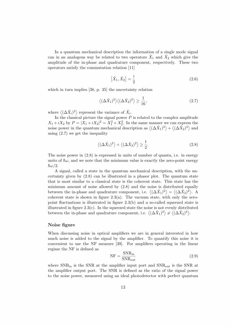
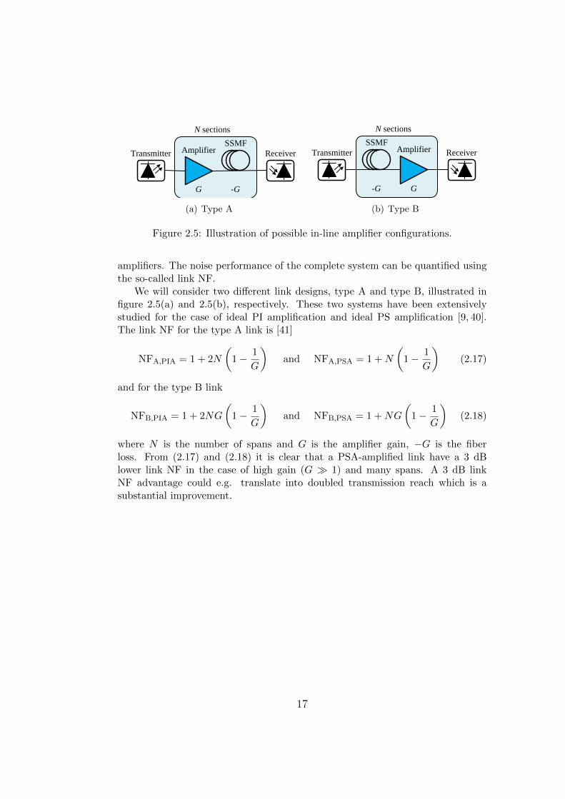
Figure 2.5: Illustration of possible in-line amplifier configurations.
amplifiers. The noise performance of the complete system can be quantified usingthe so-called link NF.
We will consider two different link designs, type A and type B, illustrated infigure 2.5(a) and 2.5(b), respectively. These two systems have been extensivelystudied for the case of ideal PI amplification and ideal PS amplification [9, 40].The link NF for the type A link is [41]
NFA,PIA = 1 + 2N
(1− 1
G
)and NFA,PSA = 1 +N
(1− 1
G
)(2.17)
and for the type B link
NFB,PIA = 1 + 2NG
(1− 1
G
)and NFB,PSA = 1 +NG
(1− 1
G
)(2.18)
where N is the number of spans and G is the amplifier gain, −G is the fiberloss. From (2.17) and (2.18) it is clear that a PSA-amplified link have a 3 dBlower link NF in the case of high gain (G � 1) and many spans. A 3 dB linkNF advantage could e.g. translate into doubled transmission reach which is asubstantial improvement.
17

18

Chapter 3
Fiber optical parametric ampli-fiers
It was early realized that FOPAs have attractive properties, e.g. high gain, largebandwidth, and capability of sub-3 dB NF, when operated in PS-mode. However,due to absence of equipment, such as high-power amplifiers and high-quality op-tical fibers with high nonlinear coefficient, the number of experimental studies onFOPAs in general and PS-FOPAs in particular has been limited.
Advances in hardware and experimental techniques has recently opened up newpossibilities to experimentally study FOPAs. These studies have confirmed thatFOPAs are very capable amplifiers and signal processing platforms. Especiallyexciting are the demonstrations of sub-3 dB NF operation.
Chapter outline
The goal of this chapter is to give a detailed description of FOPAs. We start insection 3.1 by giving an introduction to the topic. FOPAs are based on FWM,this phenomenon is described in section 3.2. In section 3.3 we describe the gainproperties of FOPAs. We introduce a transfer matrix description in section 3.4and use that to describe the difference between PI and PS parametric amplifiers.Finally, in section 3.5 we describe how FOPAs are implemented in practice.
FOPAs, operated both in PI- and PS-mode, are a central part of the work in[Paper A-C] and thus also one of the main topics of this thesis.
3.1 Introduction
FOPAs utilize FWM, a nonlinear phenomenon, to achieve amplification. The gainmechanism is called parametric amplification or parametric gain and describe theprocess when energy is transferred between several interacting waves without anyenergy storage in the medium. One possible process is when energy is transferred
19

from a strong wave (pump) to a weaker wave (signal), accompanied by the gener-ation of a third wave (idler).
Parametric amplification is a rich phenomenon and different behavior can beobtained, e.g. by varying the frequency of the interacting waves yielding differentamplification schemes. Furthermore, parametric amplification can be either PI orPS. Operated in PS-mode parametric amplifiers are capable of noiseless amplifica-tion [11]. Another feature of PS operation is the possibility to generate squeezedstates [42]. A squeezed state is a state in which the noise, or uncertainty, in onecomponent (in-phase or quadrature) is reduced at the expense of the noise in theother component.
The interaction between an electromagnetic wave and the medium it propa-gate through is governed by the material susceptibility χ [43, p. 15]. At highfield intensities not only the linear susceptibility will be of importance but alsohigher order susceptibilities, which result in a nonlinear response. In materialswithout inversion symmetry, such as many crystals, the 2nd-order susceptibilityχ(2) will be the dominating higher order susceptibility and give rise to e.g. secondharmonic generation (SHG) and sum-frequency generation. In isotropic materials,such as silica (SiO2) glass, all even-order susceptibilities vanishes and the 3rd-ordersusceptibility χ(3) will dominate.
Parametric amplification can be obtained both in χ(2) materials [44–47], andχ(3) materials [48, 49]. It is in many cases preferable to work with fiber-basedamplifiers due to compatibility with fiber optical transmission systems. In opticalfibers, which are made of silica glass, χ(3) dominate and will give rise to FWM,which can provide parametric gain. These devices are called FOPAs.
FOPAs can be operated both using pulsed and continuous wave (CW) pumps.The first FOPAs were demonstrated with pulsed pumps [48,50,51]. Using a pulsedpump, with high peak power, eases the requirements on the other parts of thesystem and high gain can be obtained over short lengths of fiber with only modestnonlinear coefficient. However, for most communication related applications a CWpump is required.
In order to demonstrate FOPAs with CW pumps, fibers with high nonlin-ear coefficient and low zero-dispersion wavelength (ZDW) variations are required.Furthermore, a high-power pump source is needed. These requirements slowed thedevelopment of FOPAs for a long time and it was not until the mid-1990’s thatprogress started to gain pace and CW pumped FOPAs were demonstrated [52].Particularly noteworthy is the first demonstration of a CW pumped FOPA withsignificant black-box gain [53].
The gain mechanism in FOPAs is fundamentally different from the mechanismthat provide gain in EDFAs, which also lead to fundamentally different amplifierproperties. The operating range and bandwidth of FOPAs is mainly determinedby the system design. FOPAs have been demonstrated with gain over a largerange of frequencies and with bandwidths as large as 81 nm using a dual-pumpedconfiguration [54]. Gain values of 70 dB have been demonstrated [14], and the
20

gain efficiency is comparable to that of Raman amplifiers with ∼ 10 mW pumppower per dB gain. A NF of 3.7 dB has been demonstrated for phase-insensitivefiber optical parametric amplifiers (PI-FOPAs) [55], and 1.1 dB at 26.5 dB gainfor PS-FOPAs [56].
A basic property of parametric amplifiers is the ultra-fast gain mechanismwith a femtosecond response time. This should be compared to the millisecondresponse time in EDFAs. While this prevent FOPAs from operating in saturationit opens up for nonlinear signal processing applications. Some demonstrations ofnonlinear signal processing using parametric effects in fibers are sampling [57],demultiplexing [58], amplitude regeneration [59], and format conversion [60].
Another property that is fundamentally connected to the gain mechanism isthe polarization dependence of the gain. This is a major drawback for transmissionsystem applications. However, at the expense of efficiency, it is possible to obtainpolarization insensitive operation using two orthogonally polarized pumps [61,62].
3.2 Four-wave mixing
FWM, also named four-photon mixing, originates from the χ(3) nonlinearity andinvolves the interaction of four waves. An intuitive understanding of the processcan be obtained by considering the refractive index modulation that is induced bya high intensity wave through the Kerr-effect.
If two waves at frequencies ω1 and ω2 co-propagate through a fiber then theywill beat at a frequency ω2 − ω1 and through this intensity beating modulate therefractive index with the same frequency. If a third wave is added, with frequencyω3, then it will become phase modulated with the frequency ω2 − ω1 and developsidebands at ω3 ± (ω2 − ω1) due to the modulated refractive index. Similarlywill ω3 beat with ω1 and phase modulate ω2 such that ω2 generate sidebands atω2± (ω3−ω1). Considering all possible combinations, new frequency componentswill be generated at ωjkl = ωj + ωk − ωl with j, k, l ∈ {1, 2, 3} [63]. Some ofthese components will overlap, either with each other or with the original waves.Components that overlap with the original waves provide gain. There will benine newly generated frequency components and these will have varying power,the stronger ones are usually referred to as idlers and the weaker ones are usuallyneglected.
For the specific case of one degenerate strong wave (pump) and one weakerwave (signal) one significant new frequency component will be generated (idler)and gain will be provided to the signal. This is the case we are dealing with in thisthesis, called single (degenerate) pump nondegenerate idler scheme. The FWMprocess is highly polarization dependent and in the discussion we will assume thatall waves have the same state of polarization over the entire interaction length.
In a quantum mechanical picture FWM can be understood as the annihila-tion of two photons and the creation of two photons, with frequencies such that
21

momentum and energy is conserved. In the case of degenerate FWM, where twowaves have the same frequency ω1, the process must satisfy 2ω1 = ω2 + ω3 and∆β = β2 + β3 − 2β1 = 0.
To get a more complete description of FWM we consider the electromagneticfields of three co-polarized waves propagating in a standard single mode fiber(SSMF). One degenerate pump wave, denoted by index p, one signal wave, denotedby index s, and an idler wave, denoted by index i. The sum of the electrical fieldscan be written as [43]
E(x, y, z) =f(x, y)
2
∑k∈{p,s,i}
{Ak(z) exp
[i(βkz − ωkt)
]}+ c.c. (3.1)
where c.c. denote the complex conjugate which is usually omitted in the calcula-tions and f(x, y) is the transverse mode profile, common for all waves. Each of thethree waves is represented by the slowly varying complex field amplitude A(z), thepropagation constant β, and the frequency ω. By inserting (3.1) into the nonlinearSchrodinger equation (NLSE) the following coupled equations can be derived [43]
dAp
dz= iγ
{[|Ap|2 + 2
(|As|2 + |Ai|2
)]Ap + 2AsAiA
∗p exp (i∆βz)
}, (3.2)
dAs
dz= iγ
{[|As|2 + 2
(|Ap|2 + |Ai|2
)]As +A∗i A
2p exp (−i∆βz)
}, (3.3)
dAi
dz= iγ
{[|Ai|2 + 2
(|Ap|2 + |As|2
)]Ai +A∗sA
2p exp (−i∆βz)
}, (3.4)
where∆β = 2βp − βs − βi (3.5)
is the propagation constant mismatch and γ is the nonlinear coefficient. In orderto arrive at this set of equations we have neglected fiber attenuation, higher-orderdispersion, any wavelength dependence of γ, and the Raman effect.
We note that the first two terms on the right hand side of (3.2)-(3.4) give riseto a nonlinear phase-shift, the first term corresponds to SPM and the second toXPM. The last term governs a power transfer between the waves and is due toFWM. It is clear that the FWM term is dependent on ∆β, which is determinedby the relative phase of the waves. We also note that XPM and SPM do not needphase-matching since they only depend on the intensity.
By defining Aj =√Pj exp(iφj) for j ∈ {p, s, i} where Pj is the power and φj is
the phase of wave j, (3.2)-(3.5) can be written as [15]
dPp
dz= −4γ(P 2
pPsPi)1/2 sin(θ), (3.6)
22

dPs
dz=dPi
dz= 2γ(P 2
pPsPi)1/2 sin(θ), (3.7)
and
dθ
dz= ∆β + γ(2Pp − Ps − Pi) +
(√P 2
pPs
Pi+
√P 2
pPi
Ps− 4√PsPi
)cos(θ) (3.8)
where θ = 2φp−φs−φi. It is clear from (3.6) and (3.7) that the FWM efficiency ismaximized for θ = π/2. This condition is referred to as the process being phase-matched. If θ = π/2 then the last term in (3.8) will be zero and in order for theprocess to stay phase-matched we need
κ = ∆β + 2γPp = 0, (3.9)
assuming that the pump power is much larger than signal and idler powers.Before we move on to discuss the phase-matching condition in more detail we
note from (3.6) and (3.7) that the direction in which the energy is transferred,from the pump to the signal and idler or from the signal and idler to the pump,depends on the relative phase θ. For the parametric gain process to be efficient it isthus important that the relative phase is kept constant throughout the interactionlength.
3.2.1 Phase-matching
Phase-matching refers to keeping the relative phase θ of the interacting waves con-stant during propagation, and is essential in order to obtain high FWM efficiency.The interacting waves will acquire a phase-shift during propagation due to linearand nonlinear effects. This is illustrated by (3.9), where the first term on theright hand side represent the linear phase-shift, which is induced by the differencein propagation constant between the waves, and the second term represent thenonlinear phase-shift which is due to SPM and XPM. In practice phase-matchingmeans making sure the linear and nonlinear phase-shifts cancel out, also referredto as nonlinear phase-matching, and the relative phase θ kept constant.
We see from (3.9) that in order for phase-matching to be feasible ∆β mustbe negative. In the single (degenerate) pump case with the pump frequency ωp
close to the fiber zero dispersion frequency ω0 the phase-matching condition canbe written as [15]
κ = β3(ωp − ω0)(ωs − ωp)2 + 2γPp = 0 (3.10)
where β3 is the third derivative of the propagation constant at ω0. From (3.10) wesee that phase-matching is only possible if the pump is in the anomalous dispersionregime, which is important to consider when designing a FOPA. From (3.10) wecan also see that there are only two signal frequencies that give κ = 0. Therewill thus be two gain maxima, one on either side of the pump. Furthermore, we
23

ω
Pump
Signal Idler
ωs ωiωp
(a)
ω
SignalIdler
Pump
ωs,ωp,ωi
(b)
ω
Pump 1 Pump 2
SignalIdler
ωs,ωiωp1 ωp2
(c)
ω
Pump 1 Pump 2
Signal Idler
ωs ωiωp1 ωp2
(d)
Figure 3.1: Illustration of single pump (a) nondegenerate idler and (b) degenerate
idler and dual pump (c) degenerate idler and (d) nondegenerate idler schemes.
note that gain bandwidth will increase with decreased dispersion slope, due to areduced dependence on the frequency selection of the waves.
In the case when no idler wave is present at the input then an idler will begenerated in the FOPA and take a phase such that the relative phase θ is π/2. Inthat case the gain is independent of the signal phase at the input and the amplifieris said to be phase-insensitive. On the other hand when the idler is present atthe input then the gain will be dependent on the signal phase and the amplifier isphase-sensitive.
3.3 Parametric amplification
Based on the previous section we can think of parametric amplification in χ(3)
media as phase-matched FWM where one or two pump waves transfer energyto a weak signal wave. Depending of how the wavelengths are selected differentschemes, with different properties, can be obtained.
A single (degenerate) pump case can be either degenerate or nondegenerateidler type, depending on how the signal frequency is chosen. According to conser-vation of energy, the waves should satisfy the relation 2ωp = ωs + ωi. This canbe done either by positioning the signal on the side of the pump or at the samefrequency as the pump. In the dual (nondegenerate) pump case the waves mustsatisfy the relation ωp1 + ωp2 = ωs + ωi. In this case we can also have either a de-generate idler or nondegenerate idler scheme. The different schemes are illustratedin figure 3.1.
The degenerate idler case is also commonly called one-mode and will automat-ically be PS. The nondegenerate idler case, also called two-mode, will be PS if anidler wave at the correct frequency is present at the input. If the idler wave isnot present then it will be generated internally, at the wavelength given by energyconservation, and the process is PI.
24

For the purpose of amplification we are interested in the amplifier gain. Anexpression for the gain can be derived from (3.2)-(3.4). We assume that the pumpwave(s) are much stronger than the signal and idler waves during the whole process,i.e. there is no pump depletion. In this case one might set dAp/dz = 0 and thesignal gain G is given by [15]
G =
{1 +
[γPp
gsinh(gLeff)
]}2
(3.11)
where g is the parametric gain coefficient given by
g =
[(γPp)2 −
(κ2
)2]
(3.12)
and Leff is the effective length defined by Leff =[1−exp(−αL)
]/α, with α denoting
the fiber loss coefficient and L the fiber length.We remind ourselves that κ describe the phase-matching and in the case of
perfect nonlinear phase-matching, i.e. when κ = 0, and γPpLeff � 1 then theexpression for the signal gain simplifies to [15]
G ≈ 1
4exp(2γPpLeff). (3.13)
We note from (3.13) that in this case the signal will grow exponentially with respectto pump power, this is called the exponential gain regime.
Another interesting regime is when there is no relative phase-shift due to disper-sion, i.e. when the signal and pump are at the same wavelength, and consequentlyκ = −2γPp. In this case the signal gain simplifies to [15]
G ≈ (2γPpLeff)2 (3.14)
and we note the quadratic dependence on the pump power. This regime is calledthe quadratic gain regime.
It is important to realize that FWM will also take place between the pump(s)and the zero-point fluctuations that are always present at all frequencies. Thiswill give rise to amplified quantum noise (AQN), also called parametric ASE.
3.4 Transfer matrix description
Using a transfer matrix to describe a system is common in a number of fields. Themethod is particularly convenient when analyzing cascaded systems, in which casea transfer matrix for the combined system is obtained simply by multiplying thetransfer matrices of the individual sub-systems. A general system with two input
25

ports and two output ports can be described by[B1
B2
]=
[s11 s12
s21 s22
]︸ ︷︷ ︸
S
[A1
A2
](3.15)
where A1 and A2 are the input modes, B1 and B2 are the output modes and S isthe transfer matrix.
In optics the modes can be represented by the complex amplitude, which con-tain information both about the amplitude and the phase. Transfer matrices canbe used to describe e.g. beam splitters and combiners, optical couplers, and para-metric processes.
A general two-mode parametric process with signal and idler gain can, whenthe pump wave(s) are treated as constant fields (no pump depletion), be describedby [64] [
Bs
B∗i
]=
[µ νν∗ µ∗
] [As
A∗i
](3.16)
where index s and i denote the signal and idler waves respectively, superscript ∗represent the complex conjugate, and µ and ν are complex transfer coefficients.The exact form of µ and ν can be found in [65], but are not important for theanalysis presented here. We will be contented by knowing that they depend onthe pump power, the phase-matching, the nonlinear interaction strength and thepolarization state. However, it is important that µ and ν satisfy the relation [64]
|µ|2 − |ν|2 = 1 (3.17)
which in practice mean that the signal and idler waves experience gain and areamplified.
To gain insight about the parametric process we evaluate (3.16) and get thetransfer function
Bs = µAs + νA∗i
Bi = νA∗s + µAi.
(3.18)
Due to the coupled propagation of the signal and idler waves it is not easy tointerpret (3.18). However, the two coupled propagation equations (3.18) can bewritten as two independent modes by carrying out the variable substitution
A+ =As +Ai√
2
A− =As −Ai√
2
(3.19)
26

which gives us, see A.1, B+ = µA+ + νA∗+
B− = µA− − νA∗−(3.20)
where B+ and B− are defined analogous to A+ and A−. We take one more stepand rewrite this set of equations, see A.2, and end up with
B+ = exp(iθ+r )[(|µ|+ |ν|
)Re(Ar,+) + i
(|µ| − |ν|
)Im(Ar,+)
]B− = exp(iθ+
r )[(|µ| − |ν|
)Re(Ar,−) + i
(|µ|+ |ν|
)Im(Ar,−)
] (3.21)
whereAr,+ = A+ exp(iθ−r ) and Ar,− = A− exp(iθ−r ) (3.22)
and
θ+r =
θµ + θν2
and θ−r =θµ − θν
2. (3.23)
The angles θµ and θν are defined by µ = |µ| exp(iθµ) and ν = |ν| exp(iθν), respec-tively. From (3.21) we see that one component of each mode, either in-phase orquadrature, will be amplified by G = (|µ| + |ν|)2 while the other component willbe attenuated by 1/G = (|µ| − |ν|)2. This is an important conclusion since it tellsus that a two wave (mode) parametric amplifier can phase-sensitively amplify twoindependent components. The relation (|µ| + |ν|)2 = 1/(|µ| − |ν|)2 can be shownusing |µ|2 − |ν|2 = 1.
Up until this point we have not considered the quantum noise in our models ofthe FOPA. In the transfer matrix description quantum noise can easily be includedby adding a noise term n to the input modes[
Bs
B∗i
]=
[µ νν∗ µ∗
] [As + ns
A∗i + n∗i
](3.24)
where ns and ni is the quantum noise associated with the signal and idler waves,respectively. The noise is taken as additive Gaussian noise that satisfies 〈nm〉 = 0,〈nmnl〉 = 0, and 〈|nm|2〉 = hωm/2 with m, l ∈ {s, i} [64]. The model given by(3.24), with the assumption of Gaussian noise at the input, is a so-called semiclas-sical model.
By evaluating 3.24 we get the transfer functionBs = µAs + νA∗i + µns + νn∗i
Bi = νA∗s + µAi + νn∗s + µni.
(3.25)
Given that the noise, ns and ni, are uncorrelated vacuum fluctuations then thenoise gain through the parametric amplifier will be |µ|2 + |ν|2, independent of the
27
signal and idler modes. As we will see below, the gain in PI-mode GPIA = |µ|2and thus the noise gain can be written as |µ|2 + |ν|2 = 2|µ|2 − 1 = 2GPIA − 1.From (3.25) we see that the noise at the output of the parametric amplifier willbe correlated. This will be of importance when studying the so-called copier-PSAscheme, used to realize PSA-amplified links, in which two parametric amplifiersare cascaded.
The model given by (3.24) is a semiclassical description of a quantum mechani-cal system. However, it has been proved that the results given by the semiclassicalmodel are of comparable accuracy with those from a complete quantum mechanicalmodel, given that the photon-number is large [17,66].
In the following sections we will analyze three cases in more detail. First thecase of PI amplification and then the case of degenerate and nondegenerate idlerPS amplification.
3.4.1 Phase-insensitive mode
In PI-mode no idler wave is present at the input, i.e. Ai = 0, and the generalinput-output relation (3.16) take the form[
Bs
B∗i
]=
[µ νν∗ µ∗
] [As
0
]. (3.26)
By evaluating (3.26) we obtain the transfer functionBs = µAs
Bi = νA∗s
(3.27)
and we see that the output signal will be the input signal amplified by GPIA = |µ|2and the output idler will be a phase-conjugated copy of the signal amplified by|ν|2 = GPIA − 1, given that θµ and θν are both zero.
Based on the previous calculation of the noise gain we can now calculate thePIA NF for the signal
NFPIA =2GPIA − 1
GPIA= 2− 1
GPIA(3.28)
which in the limit of high gain (GPIA � 1) take the value 2 (3 dB). The input andoutput modes of a PI parametric amplifier, with θµ = θν = 0 and GPIA = 8, areillustrated in figure 3.2(a).
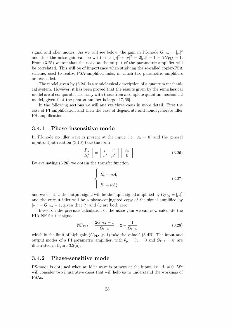
3.4.2 Phase-sensitive mode
PS-mode is obtained when an idler wave is present at the input, i.e. Ai 6= 0. Wewill consider two illustrative cases that will help us to understand the workings ofPSAs.
28

Re
Im
As
Ai
Bs
Bi
(a) PI mode (Ai = 0)
Re
Im
As
Ai Bs
Bi
(b) PS mode with Ai = As
Re
Im
As
Ai
Bs
Bi
(c) PS mode with Ai = A∗s
Figure 3.2: Illustration of input (blue) and output (red) modes for parametric
amplification with the angles θµ = θν = 0 and GPIA = 8. In all cases the noise
gain is 2GPIA − 1 while the signal and idler gain varies.
29
Phase-sensitive mode case: Ai = As
We first consider the case when the idler wave is an exact copy of the signal, i.e.Ai = As. The general input-output relation (3.16) take the form[
Bs
B∗i
]=
[µ νν∗ µ∗
] [As
A∗s
](3.29)
and by evaluating this relation we get the transfer functionBs = µAs + νA∗s
Bi = µAs + νA∗s .
(3.30)
We can immediately see from (3.30) that the output signal and idler will be iden-tical. Evaluating (3.22) we find that
Ar,+ =√
2As exp(iθ−r ) and Ar,− = 0. (3.31)
Since one of the modes is zero we can conclude that only one signal component,either in-phase or quadrature, will be amplified by GPSA = (|µ|+|ν|)2 = (
√GPIA +√
GPIA − 1)2 while the other component will be attenuated by 1/GPSA. We notethat in the limit of high gain, i.e. |µ| ≈ |ν|, then GPSA = 4GPIA, or in other wordsthe PSA gain is 6 dB higher than the PIA gain. This gain advantage is explainedby the coherent addition of the signal and idler fields.
In the same was as we calculated the signal NF for the PIA we can calculatethe signal NF for the PSA. However, since one signal component will be amplifiedand the other component attenuated we will obtain two NFs. For the amplifiedcomponent we get
NFPSA,amp =2GPIA − 1(√
GPIA +√GPIA − 1
)2 −→ 1
2, (3.32)
and for the attenuated component we get
NFPSA,att =2GPIA − 1(√
GPIA −√GPIA − 1
)2 −→ 8G2PIA (3.33)
where the limits are taken for GPIA →∞. The negative NF of -3 dB (1/2) for theamplified component might seem confusing but find its explanation in the strongnonlinear coupling between signal and idler modes at high gain. In (3.33) onlythe signal input power is considered but due to the coupling also the idler powershould be taken into account which increase the input SNR by 3 dB and thusresult in a NF of 0 dB. In figure 3.2(b) we illustrate the input and output modesof a degenerate idler PS parametric amplifier for the case when θµ = θν = 0 andGPIA = 8.
30

Phase-sensitive mode case: Ai = A∗s
The second case we consider is when the idler wave is a phase-conjugated copy ofthe signal wave, i.e. Ai = A∗s , in which case (3.16) take the form[
Bs
B∗i
]=
[µ νν∗ µ∗
] [As
As
](3.34)
and by evaluating this relation we get the transfer functionBs = µAs + νAs
Bi = µA∗s + νA∗s .
(3.35)
In this case (3.22) give us
Ar,+ =√
2Re(As) exp(iθ−r ) and Ar,− = i√
2Im(As) exp(iθ−r ), (3.36)
which tells us that both signal components will be amplified with a gain of GPSA =(|µ|+ |ν|)2. In this case the NF for both signal components is given by NFPSA,amp
and take the value -3 dB at high gain, or considering the idler power at the input,0 dB. The input and output modes, with θµ = θν = 0 and GPIA = 8, are illustratedin figure 3.2(c).
3.5 Design and implementation
The most important component in a FOPA is the optical fiber where FWM takesplace. For high efficiency operation the fiber should have high nonlinear coefficientγ, ZDW in the anomalous regime, in or close to the C-band, and low dispersionslope. Today so-called highly nonlinear fibers (HNLFs) are often used to real-ize FOPAs. Silica-based HNLFs can have a large nonlinear coefficient, about 20(W km)−1 [67]. This should be compared to the nonlinear coefficient in ordinarySSMF which is about 1.5 (W km)−1.
Although fibers with high nonlinear coefficient are available, high pump powersand long fiber sections are still needed to obtain high gain. Fibers used for FOPAsare usually in the range of 100-1000 m and EDFAs are used to reach CW pumppowers in the range of 0.5-10 W.
The amount of pump power that is launched into the HNLF, and thus alsothe FOPA gain, is limited by stimulated Brillouin scattering (SBS). SBS is similarto SRS in that pump power is absorbed by the material and then emitted as afrequency-shifted wave. In silica fibers the wave is down-shifted around 10 GHzand have a bandwidth of tens of MHz. The generated wave propagates in thebackward direction, relative to the pump, and above a certain threshold power all
31

Idler
WDM
HNLF
Filter
Pump
Signal
PCSignal
Signal
EDFA
Pump laser
Filter
RF tones
Phasemodulator
Figure 3.3: Typical implementation of a PI-FOPA with phase-modulated pump
for SBS suppression. PC: polarization controller.
additional pump power will be transferred to the down-shifted wave, thus limitingthe pump power.
Several methods for reducing SBS have been proposed. The most commonmethod is to broaden the pump spectrum using a phase modulator [68]. Anothertechnique is to concatenate several pieces of HNLF with isolators in between, inorder to block and prevent the SBS to build up [69]. There are also techniquesthat rely on frequency-shifting the backscattered wave along the fiber, either usinga temperature gradient or fiber stretching, and techniques that rely on doping thefiber, e.g. with Al or Ge.
A typical setup for a PI-FOPA using a CW pump is illustrated in figure 3.3.The pump wave originate from a laser and is then phase-modulated to reduce theSBS in the HNLF. After phase modulation the pump is boosted with an EDFAand filtered to remove ASE using a band-pass filter. The pump is then combinedwith the signal using a WDM coupler, in order minimize the coupling loss. Sincethe FWM process is polarization dependent the signal polarization has to be tunedfor highest gain. After the HNLF the signal wave is filtered out.
32

Chapter 4
Phase-sensitively amplified links
It was early established that successful implementation of PSAs in transmissionlinks would lead to a considerable performance improvement compared to whenusing PIAs. However, due to practical difficulties the first WDM compatible PSA-amplified link demonstration was published only recently.
The enabling technique for WDM compatible PSA-amplified links was the so-called copier-PSA scheme. In this scheme a PI parametric amplifier precede thePSA and generate the set of frequency- and phase-locked waves required for PS am-plification. The possible amplifier configurations that can be implemented basedon the copier-PSA scheme, with improved noise performance over conventionalPIAs, is limited to preamplifiers and inline amplifiers.
Apart from the predicted noise improvement a nonlinear penalty reduction canalso be observed when operating a PSA-amplified link in the nonlinear transmissionregion. However, the implementation of PSA-amplified links is challenging and thenoise and nonlinear penalty mitigation benefits comes at the cost of complexity.
Chapter outline
The topic of this chapter is partially covered in [Paper A-C] and some parts willtherefore be treated in less detail here. In section 4.1 we introduce the topic ofPSA-amplified links and describe the historical development of the field. Thepossibilities and limitations of the copier-PSA scheme are described in section4.2. In section 4.3 we briefly account for the possibility of nonlinear distortionmitigation in PSA-amplified links. Finally, in section 4.4 we give an overviewof the practical challenges with implementing PSA-amplified links based on thecopier-PSA scheme.
33

4.1 Introduction
Not long after it was realized that PSAs in theory are capable of noiseless am-plification [11], the possibility of implementing PSAs in long-haul communicationsystems was theoretically investigated [40,70]. Most of the early experimental workon PSAs was done using one-mode PSAs [71–73]. The reason for this was thatone-mode PSAs are comparably easy to implement, only requiring phase-lockingof the pump wave(s) and the signal wave. However one-mode PSAs have somesignificant drawbacks.
For transmission applications it is in general desirable to have a PSA imple-mentation that, apart from providing noiseless amplification, is WDM compatibleand modulation format independent. One-mode PSAs are neither WDM compat-ible nor modulation format independent. Two-mode PSAs on the other hand areboth WDM compatible and capable of modulation format independent operation.It should also be mentioned that one-mode PSAs are difficult to implement withhigh gain due to the quadratic dependence of the gain on the pump power [15],while two-mode PSAs and capable of providing high gain, growing exponentiallywith pump power [74].
A practical difficulty with two-mode PSAs is to generate the set of frequency-and phase-locked waves, often widely spaced in frequency, that is required at theinput. In a pioneering study on two-mode parametric interaction three phase-locked waves were generated using an acousto-optic modulator (AOM) and PSamplification and attenuation was observed [75]. However, using an AOM togenerate the waves is not a viable solution for transmission applications.
Due to a lack of schemes capable of generating phase-locked waves the ex-perimental research on two-mode PSAs stagnated and it took almost 20 yearsfrom the first demonstration of a two-mode PSA [75], to the first demonstra-tion of a two-mode PSA-amplified transmission link [76]. In the demonstrationthe frequency- and phase-locking of the waves was accomplished using an opticaldouble-sideband modulation scheme [77, 78], and single-channel 2.5 Gbit/s non-return-to-zero (NRZ) data transmission over a 60 km dispersion compensated linkwas accomplished.
A drawback of the optical double-sideband modulation scheme is that thebandwidth is severely limited by the bandwidth of the optical modulators used togenerate the sidebands. Frequency- and phase-locked waves can also be generatedusing a PI parametric amplifier. In this case the bandwidth is determined bythe bandwidth of the parametric amplifier, and can therefore be very large. Thecombination of a PI parametric amplifier, for generating frequency- and phase-locked waves, followed by a PSA was first introduced in [16]. The scheme iscommonly referred to as the copier-PSA scheme. An important feature of thisscheme is that it can provide modulation format independent operation.
The first reported PSA demonstration utilizing the copier-PSA scheme showedPS amplification of three WDM channels [79,80]. However, the demonstration was
34

PSAPump
Signal
copier
Idler (Ai=As*)
Figure 4.1: Conceptual illustration of the copier-PSA scheme.
mere a proof of concept of the WDM compatibility of the copier-PSA scheme andno data was transmitted and no transmission fiber of significant length was usedin the demonstration. The first demonstration of a PSA-amplified transmissionlink, over a significant span of fiber, with WDM capability and modulation formatindependence was presented in [Paper B]. The experimental setup used for thisdemonstration was based on the copier-PSA scheme.
All demonstrations of two-mode PSA-amplified links to date have used a PSAoperating as preamplifier. There have thus not been any demonstrations of multi-span inline two-mode PSA-amplified transmission links. However, multi-span in-line PSA-amplified links have been demonstrated using one-mode PSAs based onperiodically poled lithium niobate waveguides [81]. It should be mentioned thatalthough one-mode PSAs are not capable of modulation format independent op-eration they can on the other hand provide squeezing which can be used for signalregeneration [82].
4.2 Link architectures
The sub-3 dB NF of PSAs would be beneficial both in booster, inline amplifier, andpreamplifier configurations [83]. However, the copier-PSA scheme only allows forcertain amplifier configurations to be implemented with a performance advantagecompared to conventional PIAs. In the next section we describe the copier-PSAscheme and its limitations.
4.2.1 The copier-PSA scheme
The copier-PSA scheme consists of two cascaded parametric amplifiers and isschematically illustrated in figure 4.1. The working principle, leading to mod-ulation format independent operation and possibility of noiseless amplification, isas follows. If a signal wave and pump wave are injected into the first parametricamplifier then this amplifier, called copier, will operate in PI-mode and generatea phase-conjugated copy of the signal at the idler wavelength, as was shown insection 3.4. The second parametric amplifier will operate in PS-mode and amplifyboth the in-phase and quadrature components of the signal, as opposed to the
35

SSMF
× N
PSACopierPump
Transmitter
Signal
Link
Receiver
Figure 4.2: Simplified scheme for realizing PSA-amplified transmission links.
case when the idler has the same phase as the signal and one component will beattenuated.
It is clear that this scheme is modulation format independent since the signalwill experience the same gain independent of its phase, leading to amplificationof both signal components. The noise properties of the copier-PSA scheme aremore involved and requires a more detailed discussion. Qualitatively they can beunderstood as follows.
We mentioned in section 3.4 that the noise associated with the signal andidler waves will be correlated at the output of a parametric amplifier [66]. Theoutput waves from the copier will thus contain correlated noise, which in turn willprevent the PSA from noiseless amplification [66]. It is therefore essential that thenoise is decorrelated before the PSA. The requirement of decorrelating the noise iswhat limits the possible amplifier configurations for the copier-PSA scheme. Oneway to decorrelate the noise is to attenuate the waves, which e.g. can be doneby propagating them through an optical fiber [17, 41, 66]. A generic scheme forrealizing PSA-amplified links, where the loss originate from fiber attenuation, isillustrated in figure 4.2. We note that in the case of a single span (N=1), then weget a preamplifier configuration.
Since the copier operates in PI-mode it has a quantum limited NF of 3 dB.The combined NF of the copier-PSA cascade is therefore also limited to 3 dB. Thisis the explanation to why the copier-PSA scheme cannot outperform an ordinaryPIA when implemented in a booster configuration. For an inline and preamplifierconfiguration on the other hand the copier can be part of the transmitter, asillustrated in figure 4.2.
Transfer matrix description
The copier-PSA scheme can be analyzed using a transfer matrix description, sim-ilar to how we analyzed a two-mode parametric amplifier in section 3.4. On acomponent level the copier-PSA system consists of a two-mode PI parametric am-plifier followed by a loss element, which can be treated as a beam splitter [17],followed by a two-mode PS parametric amplifier. The transfer matrix equation for
36

the combined systems take the form [84][Bs
B∗i
]= G2TG1 ·
[As + ns
n∗i
](4.1)
where A and B denote input and output modes and ns and ni represents thequantum noise. G1 and G2 represent the copier and PSA transfer matrices, re-spectively, and T is an attenuation operator that satisfies
T ·A =
[ √Ts 0
0√Ts
]A +
[ √1− Tsn
′s√
1− Tin′i
]. (4.2)
where A is a vector containing two modes, e.g. the signal and idler modes after thecopier. The attenuation operator works like a 4-port beam-splitter that couplesquantum noise to the signal and idler [17]. The variable T denote the transmittanceof the fiber and n′s and n′i represents quantum noise introduced by the loss process.n′s and n′i are uncorrelated with ns and ni but have the same mean value andvariance.
Link noise figure
The copier-PSA scheme has been investigated based on (4.1) and it has been shownthat a transmission link implementation of the scheme can give up to 6 dB linkNF improvement over conventional PIA-based schemes and a 3 dB improvementover all PSA-based schemes [17, 66]. The scheme has also been investigated ex-perimentally in a copier-loss-PSA configuration [56], i.e. the link was emulatedby a lumped signal/idler loss. Based on this system amplification of dense WDMdifferential quadrature phase-shift keying (DQPSK) signals at 10 GBd with nearly6 dB SNR improvement over an EDFA-based system was demonstrated [85].
In the high-gain regime the link NF for a copier-loss-PSA and PIA-loss-PIAscheme can, respectively, be written as [17]
NFcopier-loss-PSA ≈ 1 +G2
2and NFPIA-loss-PIA ≈ 1 + 2G2 (4.3)
where G2 is the gain of the second amplifier. We see that at large gain (G2 � 1)then a copier-loss-PSA link give a 6 dB NF advantage over a PIA-loss-PIA link.
In section 2.3 we compared the link NF of ideal PIA- and PSA-amplified linksand reached the conclusion that the PSA-amplified link give a 3 dB improvement.The explanation to why the coper-PSA scheme give a 6 dB link NF improvementlies in the generation of the idler wave in the copier and that the idler is consideredto be an internal mode of the system. If the idler power was accounted for at theinput of the transmission link then a 3 dB improvement would have been obtained.
37

4.3 Nonlinear distortion mitigation
Due to PSAs capability of noiseless amplification most studies on PSA-amplifiedlinks have focused on the reduction of noise as a way to improve link performance.Another approach to improve performance is to reduce the impact of nonlineardistortion that follows an increase in transmitted power or transmission distance.
Several techniques for mitigation of nonlinear distortions have been proposed[86–88]. Mid-link optical phase conjugation (OPC) utilize an optical [87], or elec-trical [88], device to perform a phase-conjugation of the signal at the middle pointof the transmission link which result in cancellation of the nonlinear phase shiftsfrom the two halves.
In [Paper C] it was discovered that also PSAs can achieve mitigation of nonlin-ear distortions (SPM). The principle is based on that the PSA performs a coherentsummation of the signal and conjugated signal (idler) fields that after propaga-tion through the link will have acquired correlated nonlinear distortions. Throughthe coherent summation the nonlinear distortion on the two waves will cancel outwhich will lead to a performance improvement.
The concept of propagating a pair of phase-conjugated twin waves over a linkand then perform a coherent summation to cancel nonlinear impairments can alsobe implemented without the use of a PSA [89, 90]. In one demonstration twopolarization multiplexed phase-conjugated twin waves, generated using a dual po-larization optical modulator, were transmitted over a link and summed in digitalsignal processing (DSP) after coherent detection [89]. In another demonstrationthe phase-conjugated twin waves were generated using a FOPA and after propa-gation detected coherently and summed in DSP [90].
4.4 Implementation challenges
In a practical realization of a PSA-amplified transmission link based on the copier-PSA scheme several stages for conditioning of the waves have to be included.A single-span PSA amplified link, including conditioning stages, is illustrated infigure 4.3. A similar figure can be found in [Paper A] and a more comprehensivediscussion on the implementation challenges, than what will follow here, can befound in [Paper A-B].
The practical challenges can basically be divided into pump handling and wavetuning and stabilization. Pump handling refers to attenuating the strong pumpbefore the transmission link, in order to avoid nonlinear effects such as XPM andSPM in the transmission fiber, and then amplifying the pump before the PSA.The low pump power at the end of the transmission span and high requirement onthe pump quality in the PSA renders ordinary amplification by EDFAs impossible.The pump amplification can be achieved using an hybrid OIL/EDFA system whichis discussed in [Paper A].
38

PreamplifierTransmitter
Signal
Pump
PSA
Pump
recovery
Pump
attenuation
Phase/delay/
dispersion tuning
Link
Polarization
tuning
Copier
Receiver
Figure 4.3: Schematic of practical realization of PSA preamplified transmission
link.
Just after the copier, the signal, idler, and pump waves will be aligned withrespect to polarization, phase, and time. However, after transmission the align-ment will be lost and PSA amplification would not be possible it the waves werenot re-aligned. In practice this means that the transmission between the copierand the PSA has to be dispersion compensated, the time delay between the wavesmust be tuned down to a fraction of the bit slot, and the state of polarization(SOP) of the waves must be adjusted.
Furthermore, the pump recovery system requires the signal and idler waves tobe separated from the pump wave. This will result in a time dependent phasedrift between the signal/idler pair and the pump wave. This phase-drift must becompensated for continuously using a phase-locked loop (PLL).
In order to demonstrate a multi-span PSA-amplified link with WDM trans-mission there are many technical challenges that remain. These will be discussedin chapter 6.
39

40

Chapter 5
Optical injection locking
Injection locking (IL) is a general concept that can be realized in mechanical, elec-trical, and optical systems. An injection-locked laser has the capability to transferthe phase information of an injected wave while suppressing the amplitude infor-mation. This property can successfully be exploited in a pump recovery systemfor PSA-amplified transmission links.
Chapter outline
The topic of OIL is covered at length in [Paper A] and this chapter will thereforeonly serve as a short introduction to the concept. In section 5.1 we give a briefaccount of the history of IL in general and OIL in particular and in section 5.2 wedescribe some of the basic concepts of OIL.
5.1 Introduction
The concept of IL describe the phenomenon when the signal from an oscillator,e.g. a mechanical oscillator, is injected into another oscillator causing the secondoscillator to lock in frequency and phase to the first one. An early documentedobservation of this phenomenon was done by Christiaan Huygens in a letter tohis father, Constantyn Huygens, in 1665 [91]. In the letter Christiaan Huygensdescribed his observation of how the pendulums of two clocks hanging on a wall,initially swinging unsynchronized, with time became synchronized, i.e. locked infrequency and phase. He also noted that the time for reaching the synchronizedstate depended on the distance between the clocks. Later he concluded that thecause of synchronization was mechanical vibrations, originating from the clocks,mediated by the wall which they were hanging on.
IL can also be observed in electrical systems. An early study of IL in elec-tronic circuits was done by Adler in 1946 when he analyzed IL of an electricaloscillator with an external frequency source [92]. In this study he derived one
41

of the fundamental properties of IL, for locking to occur the frequency differencebetween the impressed signal and the free-running oscillator cannot be too large.Adler’s theory was later extended by Pantell in 1965 to include optical system,i.e. IL of lasers [93], and one year later, Stover and Steier demonstrated the firstinjection-locked laser using two red He-Ne lasers [94].
In the case of OIL light from one laser, termed master laser (ML), is coupledinto another laser, termed slave laser (SL), which cause the frequency and phase ofthe SL to lock to that of the ML. OIL of semiconductor distributed feedback (DFB)lasers was first demonstrated in 1991 [95], and has since found many applications.IL can e.g. significantly enhance the performance of directly modulated DFBlasers. Noticeable results have been published on single-mode performance andenhanced side-mode suppression [96], suppressed nonlinear distortion [97], reducedfrequency chirp [98], reduced relative intensity noise (RIN) and linewidth [99],enhanced resonance frequency and modulation bandwidth [100].
5.2 Basic concepts
5.2.1 Experimental implementation
There are various schemes for IL of semiconductor lasers. Two common schemesare the reflection style scheme and the transmission style scheme, illustrated infigure 5.1(a) and 5.1(b), respectively. The difference between the two schemes isin how the light is coupled in and out of the SL. In the reflection style schemeonly one facet is used for coupling while in the transmission style scheme differentfacets are used for input and output coupling. From a practical point of viewthe reflection style scheme is easier to implement since the coupling can be hard,especially if it is done using free-space optics. In both schemes the ML must beisolated from the SL. In the reflection style scheme this is done by coupling the MLlight into the SL via a circulator. In the transmission scheme it is accomplishedby placing an isolator between the ML and the SL.
Important parameters for the locking process are the power and SOP of thelight injected into the SL, the free-running output power of the SL and the free-running wavelengths of the SL and ML. For efficient locking the ML SOP hasto be matched to the mode of the SL. The importance and impact of the otherparameters will be discussed below.
5.2.2 Injection ratio
An important parameter for the IL process is the external injection ratio whichis defined as the ratio between the power injected into the SL Pinj and the free-running SL output power Pfree
R =Pinj
Pfree. (5.1)
42

VOA
PC
Slave laser
Master laser Circulator
nML
nML
nML nSL
(a) Reflection style configuration
VOA
PCMaster laserIsolator
Slave laser
(b) Transmission style configuration
Figure 5.1: Illustration of common configurations for realizing OIL. VOA: variable
optical attenuator.
The internal injection ratio is defined by instead using the injected power internalto the SL cavity and the internal power of the free-running SL. For practical reasonsthe external injection ratio is most common in experimental studies.
5.2.3 Locking bandwidth
The frequency difference between the injected light νinj and the free-running SLνfree is also an important parameter for the locking process. Locking of the SLto the ML will only be possible within a certain range of the frequency difference∆ν = νinj − νfree. The range within which the locking occur is called the lockingbandwidth and is determined by, among other things, the injection ratio.
5.2.4 Theoretical explanation models
Several models have been developed to describe the locking dynamics of OIL.The gain competition model was introduced in [101] and describe the competitionbetween ASE and injected light. Another way to understand the dynamics of theOIL process is through the phasor diagram model [101]. This model describes howthe steady-state is reached. The third approach is to use the rate-equations whichcan give us an expression for the locking bandwidth [102].
43

44
Chapter 6
Outlook
PSAs have now proved capable of outperforming EDFAs in terms of sensitivityfor single-span preamplifier configurations, both in the linear [Paper B] and non-linear [Paper C] transmission regime. These results are intriguing and motivate,by themselves, continued research on PSA-amplified transmission links. However,from a commercial perspective sensitivity is not the only measure that is importantwhen comparing amplification technologies. Considering issues such as polariza-tion dependent gain and the practical difficulty of ensuring that the phase relationbetween the waves is stable, PSAs still have a long way to go before they can beconsidered commercially interesting as transmission link amplifiers.
Looking beyond the issues mentioned above, some conceptually interesting andimportant PSA-amplified link demonstrations would be to show WDM transmis-sion, transmission of more advanced modulation formats such as 16QAM, andmulti-span transmission. The main challenge for demonstrating WDM transmis-sion is to achieve independent polarization tuning of the WDM channels. Forpractical reasons a multi-span transmission experiment would preferably be car-ried out in a re-circulating loop configuration. Possible issues for that kind ofdemonstration might be noise accumulation on the pump wave and difficulties toachieve continuous phase-stabilization of the waves.
There are a few ways in which development of techniques or components couldlead to better or simpler PSAs. SBS is an issue in all high-gain PSA implemen-tations and in most cases techniques such as pump phase modulation are used toreduce the SBS. A breakthrough in SBS suppression techniques, enabling high-gain PSAs without the need of pump phase modulation, would make it possibleto implement PSAs that do not suffer from broadened idler spectrum, which leadto performance degradation in some applications.
Another field where development could lead to improved PSA performanceis in the field of optical fibers. New fibers with higher nonlinear coefficient andlower loss would e.g. make it possible to use shorter fibers which in turn easethe requirements on other aspects of the fiber, such as zero dispersion wavelengthvariations. Holey-fibers could be one such fiber type that can be used for PSAs.
45

46

Chapter 7
Summary of papers
Paper A: Injection locking-based pump recov-
ery for phase-sensitive amplified links
Compared to conventional EDFA-amplified transmission links, PSA-amplified linkswould give a significant performance improvement. In order to realize PSA-amplified links with significant span lengths a pump recovery system, capableof generating a high-quality pump wave from the residual pump wave after thetransmission span, is required. In this paper we demonstrate, for the first time, anIL-based pump recovery system, enabling PSA-amplified links with more than 200km long spans. Bit error ratio (BER) measurements with 10 GBd DQPSK signalsshow penalty-free recovery of a pump wave, phase modulated with two sinusoidalRF-tones at 0.1 GHz and 0.3 GHz, with 64 dB amplification, from -30 dBm to 34dBm. To understand the operating power limits for the pump recovery system thenoise generation in and the phase modulation transfer through the pump recoverysystem is quantified and the corresponding link penalties measured and explained.
Paper B: Phase-sensitive Optical Pre-Amplifier
Implemented in an 80km DQPSK Link
The ultra-low NF of PSAs makes them very attractive for use in fiber opticaltransmission links. There are a number of challenges in implementing a frequency-nondegenerate PSA-amplified link with a long transmission span. First of all apump recovery system must be incorporated into the link in order to generatea high-quality pump before the PSA. In addition to this the pump, signal, andidler waves, possibly widely spaced in frequency, must be temporally synchronizedafter dispersion in the fiber link and tuned to have the same state of polariza-tion at the input of the PSA. In this paper we demonstrate a record long 80 km
47

frequency-nondegenerate PSA-amplified transmission link. We measure 1.3 dBhigher sensitivity for the PSA-amplified link compared to a comparable conven-tional EDFA-amplified link.
Paper C: Phase-Sensitive Amplified Optical Link
Operating in the Nonlinear Transmission Regime
The key factor limiting the capacity in fiber optical transmission systems is theSNR. The SNR can be increased by launching higher signal power into the link.However, nonlinear effects set an upper bound on how high power that can belaunched. In this paper we present the first characterization of a PSA-amplifiedlink operating in the nonlinear transmission regime. We observe less nonlinearpenalty in the PSA-amplified link compared to an EDFA-amplified link and alsothe PSA modify the distribution of nonlinear phase noise on the signal.
48
Bibliography
[1] T. H. Maiman, “Stimulated Optical Radiation in Ruby,” Nature 187, 493–494 (1960).
[2] K. C. Kao and G. A. Hockham, “Dielectric-fibre surface waveguides for opti-cal frequencies,” Proceedings of the Institution of Electrical Engineers 113,1151–1158 (1966).
[3] S. B. Poole, D. N. Payne, R. J. Mears, M. E. Fermann, and R. I. Laming,“Fabrication and Characterization of Low-Loss Optical Fibers ContainingRare-Earth Ions,” Journal of Lightwave Technology LT-4, 870–876 (1986).
[4] T. C. Cannon, D. L. Pope, and D. D. Sell, “Installation and Performance ofthe Chicago Lightwave Transmission System,” IEEE Transactions on Com-munications COM-26, 1056–1060 (1978).
[5] T. J. Xia, G. A. Wellbrock, A. Tanaka, M.-F. Huang, E. Ip, D. Qian, Y.-K.Huang, S. Zhang, Y. Zhang, P. N. Ji, Y. Aono, S. Murakami, and T. Tajima,“High Capacity Field Trials of 40.5 Tb/s for LH Distance of 1,822 km and54.2 Tb/s for Regional Distance of 634 km,” in “Optical Fiber Commu-nication Conference and Exposition (OFC) and National Fiber Optic En-gineers Conference (NFOEC) ,” (Optical Society of America, Washington,DC, 2013), p. PDP5A.4.
[6] A. H. Gnauck, R. W. Tkach, A. R. Chraplyvy, and T. Li, “High-CapacityOptical Transmission Systems,” Journal of Lightwave Technology 26, 1032–1045 (2008).
[7] M. Hirano, T. Haruna, Y. Tamura, T. Kawano, S. Ohnuki, Y. Yamamoto,Y. Koyano, and T. Sasaki, “Record Low Loss, Record High FOM Opti-cal Fiber with Manufacturable Process,” in “Optical Fiber CommunicationConference and Exposition (OFC) and National Fiber Optic Engineers Con-ference (NFOEC) ,” (Optical Society of America, Washington, DC, 2013),p. PDP5A.7.
[8] C. E. Shannon, “Communication in the Presence of Noise,” Proceedings ofthe IRE 37, 10–21 (1949).
[9] E. Desurvire, Erbium-doped Fiber Amplifiers (John Wiley & Sons, 1994).
49

[10] R. I. Laming, M. N. Zervas, and D. N. Payne, “Erbium-Doped Fiber Ampli-fier with 54 dB Gain and 3.1 dB Noise Figure,” IEEE Photonics TechnologyLetters 4, 1345–1347 (1992).
[11] C. M. Caves, “Quantum limits on noise in linear amplifiers,” Physical ReviewD 26, 1817–1839 (1982).
[12] H. Masuda, S. Kawai, and K. I. Suzuki, “Optical SNR enhanced amplifica-tion in long-distance recirculating-loop WDM transmission experiment using1580 nm band hybrid amplifier,” Electronics Letters 35, 411–412 (1999).
[13] E. Pincemin, T. Guillossou, N. Evanno, S. Lobanov, and S. Ten, “Recordtransmission distances over Ultra Low Loss G.652 fibre with NRZ-OOK orNRZ-DPSK 40 Gbps WDM systems,” in “Optical Fiber CommunicationConference and Exposition (OFC) and National Fiber Optic Engineers Con-ference (NFOEC) ,” (Optical Society of America, Washington, DC, 2009),p. OThC2.
[14] T. Torounidis, P. A. Andrekson, and B.-E. Olsson, “Fiber-Optical Paramet-ric Amplifier With 70-dB Gain,” IEEE Photonics Technology Letters 18,1194–1196 (2006).
[15] J. Hansryd, P. A. Andrekson, M. Westlund, J. Li, and P.-O. Hedekvist,“Fiber-Based Optical Parametric Amplifiers and Their Applications,” IEEEJournal of Selected Topics in Quantum Electronics8, 506–520 (2002).
[16] R. Tang, J. Lasri, P. S. Devgan, V. Grigoryan, P. Kumar, and M. Vasilyev,“Gain characteristics of a frequency nondegenerate phase-sensitive fiber-optic parametric amplifier with phase self-stabilized input,” Optics Express13, 10483–10493 (2005).
[17] C. J. McKinstrie, M. Karlsson, and Z. Tong, “Field-quadrature and photon-number correlations produced by parametric processes,” Optics Express 18,19792–19823 (2010).
[18] E. Lach and W. Idler, “Modulation formats for 100G and beyond,” OpticalFiber Technology 17, 377–386 (2011).
[19] H. Heffner, “The Fundamental Noise Limit of Linear Amplifiers,” Proceed-ings of the IRE pp. 1604–1608 (1962).
[20] H. A. Haus and J. A. Mullen, “Quantum Noise in Linear Amplifiers,” Phys-ical Review 128, 2407–2413 (1962).
[21] R. J. Mears, L. Reekie, I. M. Jauncey, and D. N. Payne, “Low-noise erbium-doped fibre amplifier operating at 1.54µm,” Electronics Letters 23, 1026–1028 (1987).
[22] M. N. Islam, “Raman Amplifiers for Telecommunications,” IEEE Journal ofSelected Topics in Quantum Electronics8, 493–494 (2002).
[23] M. J. Connelly, Semiconductor Optical Amplifiers (Kluwer, 2004).
[24] F. A. Flood, “L-Band Erbium-Doped Fiber Amplifiers,” in “Optical FiberCommunication Conference and Exposition (OFC) and National Fiber Optic
50

Engineers Conference (NFOEC) ,” (Optical Society of America, Washington,DC, 2000), pp. WG1–2.
[25] J. B. Rosolem and A. A. Juriollo, “S Band EDFA Using Standard ErbiumDoped Fiber, 1450 nm Pumping and Single Stage ASE Filtering,” in “Op-tical Fiber Communication Conference and Exposition (OFC) and NationalFiber Optic Engineers Conference (NFOEC) ,” (Optical Society of America,Washington, DC, 2008), p. OTuN3.
[26] S. Aozasa, H. Masuda, H. Ono, T. Sakamoto, T. Kanamori, Y. Ohishi, andM. Shimizu, “1480-1510 nm-band Tm doped fiber amplifier (TDFA) with ahigh power conversion efficiency of 42 %,” in “Optical Fiber CommunicationConference and Exposition (OFC) and National Fiber Optic Engineers Con-ference (NFOEC) ,” (Optical Society of America, Washington, DC, 2001),pp. PD1–3.
[27] J. Bromage, “Raman Amplification for Fiber Communications Systems,”Journal of Lightwave Technology 22, 79–93 (2004).
[28] X. Li and G. Li, “Electrical Postcompensation of SOA Impairments forFiber-Optic Transmission,” IEEE Photonics Technology Letters 21, 581–583 (2009).
[29] A. E. Kelly, I. F. Lealman, L. J. Rivers, S. D. Perrin, and M. Silver, “Lownoise figure (7.2 dB) and high gain (29 dB) semiconductor optical amplifierwith a single layer AR coating,” Electronics Letters 33, 536–538 (1997).
[30] E. J. Woodbury and W. K. Ng, “Ruby Laser Operating in the Near IR,”Proceedings of the IRE 50, 2367 (1962).
[31] G. Eckhardt, R. W. Hellwarth, F. J. McClung, S. E. Schwarz, D. Weiner,and E. J. Woodbury, “Stimulated raman scattering from organic liquids,”Physical Review Letters 9, 455–457 (1962).
[32] R. H. Stolen and E. P. Ippen, “Raman gain in glass optical waveguides,”Applied Physics Letters 22, 276–278 (1973).
[33] C. V. Raman and K. S. Krishnan, “A New Type of Secondary Radiation,”Nature 121, 501–502 (1928).
[34] E. Desurvire, M. Papuchon, J. P. Pocholle, and J. Raffy, “High-gain opti-cal amplification of laser diode signal by Raman scattering in single-modefibres,” Electronics Letters 19, 751–753 (1983).
[35] R. Loudon, The quantum theory of light (Oxford University Press, 2000).
[36] D. Marcuse, Principles of quantum electronics (Academic press, 1980).
[37] Y. Yamamoto and K. Inoue, “Noise in Amplifiers,” Journal of LightwaveTechnology 21, 2895–2915 (2003).
[38] J. J. Sakurai, Modern Quantum Mechanics (Addison Wesley Longman,1994).
[39] H. T. Friis, “Noise Figures of Radio Receivers,” Proceedings of the IRE 32,419–422 (1944).
51

[40] R. Loudon, “Theory of Noise Accumulation in Linear Optical-AmplifierChains,” IEEE Journal of Quantum Electronics QE-21, 766–773 (1985).
[41] Z. Tong, C. J. McKinstrie, C. Lundstrom, M. Karlsson, and P. A. Andrek-son, “Noise performance of optical fiber transmission links that use non-degenerate cascaded phasesensitive amplifiers,” Optics Express 18, 15426–15439 (2010).
[42] D. F. Walls, “Squeezed states of light,” Nature 306, 141–146 (1983).
[43] G. P. Agrawal, Nonlinear Fiber Optics, 5th Ed. (Academic Press, 2012).
[44] J. A. Armstrong, N. Bloembergen, J. Ducuing, and P. S. Pershan, “Interac-tions between Light Waves in a Nonlinear Dielectric,” Physical Review 127,1918–1939 (1962).
[45] N. M. Kroll, “Parametric Amplification in Spatially Extended Media andApplication to the Design of Tuneable Oscillators at Optical Frequencies,”Physical Review 127, 1207–1211 (1962).
[46] S.-K. Choi, R.-D. Li, C. Kim, and P. Kumar, “Traveling-wave optical para-metric amplifier: investigation of its phase-sensitive and phase-insensitivegain response,” Journal of the Optical Society of America B 14, 1564–1575(1997).
[47] D. J. Lovering, J. A. Levenson, P. Vidakovic, J. Webjorn, and P. S. J.Russell, “Noiseless optical amplification in quasi-phase-matched bulk lithiumniobate,” Opt. Lett.21, 1439–1441 (1996).
[48] R. H. Stolen, “Phase-Matched-Stimulated Four-Photon Mixing in Silica-Fiber Waveguides,” IEEE Journal of Quantum Electronics QE-11, 100–103(1975).
[49] R. H. Stolen and J. E. Bjorkholm, “Parametric Amplification and FrequencyConversion in Optical Fibers,” IEEE Journal of Quantum Electronics QE-17, 1062–1072 (1982).
[50] C. Lin, W. A. Reed, A. D. Pearson, and H. T. Shang, “Phase matching in theminimum-chromatic-dispersion region of single-mode fibers for stimulatedfour-photon mixing,” Optics Letters 6, 493–495 (1981).
[51] K. Washio, K. Inoue, and S. Kishida, “Efficient large-frequency-shifted three-wave mixing in low dispersion wavelength region in single-mode optical fi-bre,” Electronics Letters 16, 658–660 (1980).
[52] F. Yang, M. Marhic, and L. Kazovsky, “CW fibre optical parametric am-plifier with net gain and wavelength conversion efficiency > 1,” ElectronicsLetters 32, 2336–2338 (1996).
[53] J. Hansryd and P. A. Andrekson, “Broad-Band Continuous-Wave-PumpedFiber Optical Parametric Amplifier with 49-dB Gain and Wavelength-Conversion Efficiency,” IEEE Photonics Technology Letters 13, 194–196(2001).
[54] J. C. Boggio, C. Lundstrom, J. Yang, H. Sunnerud, and P. Andrekson,“Double-pumped FOPA with 40 dB flat gain over 81 nm bandwidth,” in
52
“European Conference and Exhibition on Optical Communication (ECOC),” (Optical Society of America, Washington, DC, 2008), p. Tu.3.B.5.
[55] P. L. Voss, R. Tang, and P. Kumar, “Measurement of the photon statisticsand the noise figure of a fiber-optic parametric amplifier,” Optics Letters 28,549–551 (2003).
[56] Z. Tong, C. Lundstrom, P. A. Andrekson, C. J. McKinstrie, M. Karlsson,D. J. Blessing, E. Tipsuwannakul, B. J. Puttnam, H. Toda, and L. Gruner-Nielsen, “Towards ultrasensitive optical links enabled by low-noise phase-sensitive amplifiers,” Nature Photonics 5, 430–436 (2011).
[57] P. A. Andrekson, “Picosecond optical sampling using four-wave mixing infibre,” Electronics Letters 27, 1440–1441 (1991).
[58] P. A. Andrekson, N. A. Olsson, J. R. Simpson, T. Tanbun-ek, R. A. Lo-gan, and M. Haner, “16 Gbit/s all-optical demultiplexing using four-wavemixing,” Electronics Letters 27, 922–924 (1991).
[59] K. Inoue, “Optical level equalisation based on gain saturation in fibre opticalparametric amplifier,” Electronics Letters 36, 1016–1017 (2000).
[60] G.-W. Lu and T. Miyazaki, “Optical phase erasure based on FWM in HNLFenabling format conversion from 320-Gb/s RZDQPSK to 160-Gb/s RZ-DPSK,” Optics Express 17, 13346–13353 (2009).
[61] R. Jopson and R. Tench, “Polarisation-independent phase conjugation oflightwave signals,” Electronics Letters 29, 2216–2217 (1993).
[62] K. Inoue, “Polarization Independent Wavelength Conversion Using FiberFour-Wave Mixing with Two Orthogonal Pump Lights of Different Frequen-cies,” Journal of Lightwave Technology 12, 1916–1920 (1994).
[63] M. O. van Deventer, Fundamentals of Bidirectional Transmission over aSingle Optical Fibre, vol. 2 of Solid-State Science and Technology Library(Springer, 1996).
[64] C. J. McKinstrie, S. Radic, and M. G. Raymer, “Quantum noise propertiesof parametric amplifiers driven by two pump waves,” Optics Express 12,5037–5066 (2004).
[65] M. Vasilyev, “Distributed phase-sensitive amplification,” Optics Express 13,7563–7571 (2005).
[66] Z. Tong, A. Bogris, C. Lundstrom, C. J. McKinstrie, M. Vasilyev, M. Karls-son, and P. A. Andrekson, “Modeling and measurement of the noise figureof a cascaded non-degenerate phase-sensitive parametric amplifier,” OpticsExpress 18, 14820–14835 (2010).
[67] M. Hirano, T. Nakanishi, T. Okuno, and M. Onishi, “Silica-Based HighlyNonlinear Fibers and Their Application,” IEEE Journal of Selected Topicsin Quantum Electronics15, 103–113 (2009).
[68] S. K. Korotky, P. B. Hansen, L. Eskildsen, and J. J. Veselka, “Efficientphase modulation scheme for suppressing stimulated brillouin scattering,”
53

in “Proc. Technol. Dig. Conf. Integr. Opt. Fiber Commun.”, (1995), pp.110–111.
[69] C. Lundstrom, R. Malik, L. Gruner-Nielsen, B. Corcoran, S. L. I. Olsson,M. Karlsson, and P. A. Andrekson, “Fiber Optic Parametric Amplifier With10-dB Net Gain Without Pump Dithering,” IEEE Photonics TechnologyLetters 25, 234–237 (2013).
[70] H. P. Yuen, “Design of transparent optical networks by using novel quantumamplifiers and sources,” Optics Letters 12, 789–791 (1987).
[71] M. Shirasaki and H. A. Haus, “Squeezing of pulses in a nonlinear interfer-ometer,” Journal of the Optical Society of America B 7, 30–34 (1990).
[72] M. E. Marhic, C. H. Hsia, and J. M. Jeong, “Optical amplification in anonlinear fibre interferometer,” Optics Letters 27, 210–211 (1991).
[73] W. Imajuku and A. Takada, “Error-free operation of in-line phase-sensitiveamplifier,” Electronics Letters 34, 1673–1674 (1998).
[74] J. Kakande, C. Lundstrom, P. A. Andrekson, Z. Tong, M. Karlsson,P. Petropoulos, F. Parmigiani, and D. J. Richardson, “Detailed character-ization of a fiber-optic parametric amplifier in phase-sensitive and phase-insensitive operation,” Optics Express 18, 4130–4137 (2010).
[75] I. Bar-Joseph, A. A. Friesem, R. G. Waarts, and H. H. Yaffe, “Parametricinteraction of a modulated wave in a single-mode fiber,” Optics Letters 11,534–536 (1986).
[76] R. Tang, P. Devgan, V. S. Grigoryan, and P. Kumar, “Inline frequency-non-degenerate phase-sensitive fibre parametric amplifier for fibre-optic commu-nication,” Electronics Letters 41, 1072–1074 (2005).
[77] R. Tang, P. Devgan, P. L. Voss, V. S. Grigoryan, and P. Kumar, “In-LineFrequency-Nondegenerate Phase-Sensitive Fiber-Optical Parametric Ampli-fier,” IEEE Photonics Technology Letters 17, 1845–1847 (2005).
[78] O. K. Lim, V. Grigoryan, M. Shin, and P. Kumar, “Ultra-Low-Noise InlineFiber-Optic Phase-Sensitive Amplifier for Analog Optical Signals,” in “Op-tical Fiber Communication Conference and Exposition (OFC) and NationalFiber Optic Engineers Conference (NFOEC) ,” (Optical Society of America,Washington, DC, 2008), p. OML3.
[79] R. Tang, P. S. Devgan, V. S. Grigoryan, P. Kumar, and M. Vasilyev, “In-linephase-sensitive amplification of multichannel CW signals based on frequencynondegenerate four-wave-mixing in fiber,” Optics Express 16, 9046–9053(2008).
[80] R. Tang, M. Shin, P. Devgan, V. S. Grigoryan, M. Vasilyev, and P. Ku-mar, “Toward in-line phase-sensitive fiber-parametric amplification of mul-tichannel signals,” in “Conference on Lasers and Electro-Optics (CLEO) ,”(Optical Society of America, Washington, DC, 2006), p. JThC81.
54

[81] T. Umeki, M. Asobe, H. Takara, Y. Miyamoto, and H. Takenouchi, “Multi-span transmission using phase and amplitude regeneration in PPLN-basedPSA,” Optics Express 21, 18170–18177 (2013).
[82] R. Slavık, F. Parmigiani, J. Kakande, C. Lundstrom, M. Sjodin, P. A.Andrekson, R. Weerasuriya, S. Sygletos, A. D. Ellis, L. Gruner-Nielsen,D. Jakobsen, S. Herstrøm, R. Phelan, J. O′Gorman, A. Bogris, D. Syvridis,S. Dasgupta, P. Petropoulos, and D. J. Richardson, “All-optical phase andamplitude regenerator for next-generation telecommunications systems,”Nature Photonics 4, 690–695 (2010).
[83] Y. Yamamoto and T. Mukai, “Fundamentals of optical amplifiers,” Opticaland Quantum Elecctronics 21, S1–S14 (1989).
[84] Z. Tong, C. Lundstrom, P. A. Andrekson, M. Karlsson, and A. Bogris, “Ul-tralow Noise, Broadband Phase-Sensitive Optical Amplifiers, and Their Ap-plications,” IEEE Journal of Selected Topics in Quantum Electronics18,1016–1032 (2012).
[85] Z. Tong, C. Lundstrom, E. Tipsuwannakul, M. Karlsson, and P. A. An-drekson, “Phase-Sensitive Amplified DWDM DQPSK Signals Using Free-Running Lasers with 6-dB Link SNR Improvement over EDFA-based Sys-tems,” in “European Conference and Exhibition on Optical Communication(ECOC) ,” (Optical Society of America, Washington, DC, 2010), p. PDP1.3.
[86] E. Ip and J. M. Kahn, “Compensation of Dispersion and Nonlinear Impair-ments Using Digital Backpropagation,” Journal of Lightwave Technology 26,3416–3425 (2008).
[87] S. L. Jansen, D. van den Borne, B. Spinnler, S. Calabro, H. Suche, P. M.Krummrich, W. Sohler, G.-D. Khoe, and H. de Waardt, “Optical PhaseConjugation for Ultra Long-Haul Phase-Shift-Keyed Transmission,” Journalof Lightwave Technology 24, 54–64 (2006).
[88] E. F. Mateo, X. Zhou, and G. Li, “Electronic phase conjugation for non-linearity compensation in fiber communication systems,” in “Optical FiberCommunication Conference and Exposition (OFC) and National Fiber OpticEngineers Conference (NFOEC) ,” (Optical Society of America, Washington,DC, 2011), p. JWA25.
[89] X. Liu, A. R. Chraplyvy, P. J. Winzer, R. W. Tkach, and S. Chandrasekhar,“Phase-conjugated twin waves for communication beyond the Kerr nonlin-earity limit,” Nature Photonics 7, 560–568 (2013).
[90] Y. Tian, Y.-K. Huang, S. Zhang, P. R. Prucnal, , and T. Wang, “Demonstra-tion of digital phase-sensitive boosting to extend signal reach for long-haulWDM systems using optical phase-conjugated copy,” Optics Express 21,5099–5106 (2013).
[91] A. Pikovsky, M. Rosenblum, and J. Kurths, Synchronization: A Univer-sal Concept in Nonlinear Sciences, vol. 12 of Cambridge Nonlinear ScienceSeries (Cambridge University Press, 2003).
55

[92] R. Adler, “A Study of Locking Phenomena in Oscillators,” Proceedings ofthe IRE 34, 351–357 (1946).
[93] R. H. Pantell, “The Laser Oscillator with an External Signal,” Proceedingsof the IEEE 53, 474–477 (1965).
[94] H. L. Stover and W. H. Steier, “Locking of laser oscillators by light injection,”Applied Physics Letters 8, 91–93 (1966).
[95] R. Hui, A. D’Ottavi, A. Mecozzi, and P. Spano, “Injection Locking in Dis-tributed Feedback Semiconductor Lasers,” IEEE Journal of Quantum Elec-tronics 27, 1688–1695 (1991).
[96] K. Iwashita and K. Nakagawa, “Suppression of Mode Partition Noise byLaser Diode Light Injection,” IEEE Journal of Quantum Electronics QE-18, 1669–1674 (1982).
[97] X. J. Meng, T. Chau, D. T. K. Tong, and M. Wu, “Suppression of secondharmonic distortion in directly modulated distributed feedback lasers byexternal light injection,” Electronics Letters 34, 2040–2041 (1998).
[98] C. Lin and F. Mengel, “Reduction of frequency chirping and dynamiclinewidth in high-speed directly modulated semiconductor lasers by injec-tion locking,” Electronics Letters 20, 1073–1075 (1984).
[99] N. Schunk and K. Petermann, “Noise Analysis of Injection-Locked Semi-conductor Injection Lasers,” IEEE Journal of Quantum Electronics QE-22,642–650 (1986).
[100] E. K. Lau, L. J. Wong, X. Zhao, Y.-K. Chen, C. J. Chang-Hasnain, and M. C.Wu, “Bandwidth Enhancement by Master Modulation of Optical Injection-Locked Lasers,” Journal of Lightwave Technology 26, 2584–2593 (2008).
[101] C. H. Henry, N. A. Olsson, and N. K. Dutta, “Locking Range and Stabilityof Injection Locked 1.54 µm InGaAsP Semiconductor Lasers,” IEEE Journalof Quantum Electronics QE-21, 1152–1156 (1985).
[102] R. Lang, “Injection Locking Properties of a Semiconductor Laser,” IEEEJournal of Quantum Electronics QE-18, 976–983 (1982).
56

Appendix A
Derivations
A.1 Derivation of B+(A+) and B−(A−)
We take our starting point in (3.19)A+ =
As +Ai√2
A− =As −Ai√
2
(A.1)
⇒As =
A+ +A−√2
Ai =A+ −A−√
2
(A.2)
We can now define B+ and B− and show (3.20) using (3.18) and (A.2). Weget
B+ =Bs +Bi√
2=µAs + νA∗i + νA∗s + µAi√
2(A.3)
=µ(A+ +A−) + ν(A+ −A−)∗ + ν(A+ +A−)∗ + µ(A+ −A−)
2= µA+ + νA∗+
and
B− =Bs −Bi√
2=µAs + νA∗i − (νA∗s + µAi)√
2(A.4)
=µ(A+ +A−) + ν(A+ −A−)∗ −
[ν(A+ +A−)∗ + µ(A+ −A−)
]2
= µA− − νA∗−.
57

A.2 Derivation of B+(Ar,+) and B−(Ar,−)
B+ = µA+ + νA∗+ = |µ| exp(iθµ)A+ + |ν| exp(iθν)A∗+ =
[θ+
r =θµ + θν
2
]=
= exp(iθ+r )
[|µ| exp
(i2θµ − θµ − θν
2
)A+ + |ν| exp
(i2θν − θµ − θν
2
)A∗+
]
=
[θ−r =
θµ − θν2
]= exp(iθ+
r )[|µ| exp(iθ−r )A+ + |ν| exp(−iθ−r )A∗+
]=
=[Ar,+ = A+n exp(iθ−r )
]= exp(iθ+
r )(|µ|Ar,+ + |ν|A∗r,+
)=
= exp(iθ+r ){|µ|[Re(Ar,+) + iIm(Ar,+)
]+ |ν|
[Re(Ar,+)− iIm(Ar,+)
]}= exp(iθ+
r )[(|µ|+ |ν|)Re(Ar,+) + i(|µ| − |ν|)Im(Ar,+)
](A.5)
B− = µA− − νA∗− = |µ| exp(iθµ)A− − |ν| exp(iθν)A∗− =
[θ+
r =θµ + θν
2
]=
= exp(iθ+r )
[|µ| exp
(i2θµ − θµ − θν
2
)A− − |ν| exp
(i2θν − θµ − θν
2
)A∗−
]
=
[θ−r =
θµ − θν2
]= exp(iθ+
r )[|µ| exp(iθ−r )A− − |ν| exp(−iθ−r )A∗−
]=
=[Ar,- = A− exp(iθ−r )
]= exp(iθ+
r )(|µ|Ar,- − |ν|A∗r,-
)=
= exp(iθ+r ){|µ|[Re(Ar,-) + iIm(Ar,-)
]− |ν|
[Re(Ar,-)− iIm(Ar,-)
]}= exp(iθ+
r )[(|µ| − |ν|)Re(Ar,-) + i(|µ|+ |ν|)Im(Ar,-)
](A.6)
58