toward a new sub-component test method for the trailing edge region of wind turbine blades
TRANSCRIPT

Toward a New Sub-component Test Method for the Trailing Edge Region of Wind Turbine Blades
Kim Branner, Peter Berring & Philipp Ulrich Haselbach
Department of Wind Energy, Technical University of DenmarkEmail: [email protected]

DTU Wind Energy, Technical University of DenmarkAdd Presentation Title in Footer via ”Insert”; ”Header & Footer”
Outline
• Background & motivation• Proposed subcomponent test method• Comparison of simulations for full-scale test and
subcomponent test • Conclusions and ongoing work

DTU Wind Energy, Technical University of DenmarkAdd Presentation Title in Footer via ”Insert”; ”Header & Footer”
Certification of wind turbine blades
• The design of wind turbine blades incorporates tests on normally only two scales.
• Test of material coupons (level 1) is performed in order to determine material properties.
• Full-scale blade tests (level 3) is performed on typically one or two blades in order to verify that the blade type have the load carrying capability and service life provided for in the design.
3 19 September
2016
DTU Wind Energy, Technical University of DenmarkAdd Presentation Title in Footer via ”Insert”; ”Header & Footer”
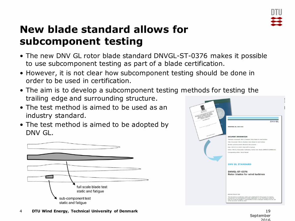
New blade standard allows for subcomponent testing• The new DNV GL rotor blade standard DNVGL-ST-0376 makes it possible
to use subcomponent testing as part of a blade certification.• However, it is not clear how subcomponent testing should be done in
order to be used in certification.• The aim is to develop a subcomponent testing methods for testing the
trailing edge and surrounding structure.• The test method is aimed to be used as an
industry standard.• The test method is aimed to be adopted by
DNV GL.
4 19 September
2016
DTU Wind Energy, Technical University of DenmarkAdd Presentation Title in Footer via ”Insert”; ”Header & Footer”
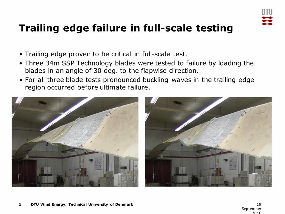
Trailing edge failure in full-scale testing
• Trailing edge proven to be critical in full-scale test.• Three 34m SSP Technology blades were tested to failure by loading the
blades in an angle of 30 deg. to the flapwise direction.• For all three blade tests pronounced buckling waves in the trailing edge
region occurred before ultimate failure.
5 19 September
2016

DTU Wind Energy, Technical University of DenmarkAdd Presentation Title in Footer via ”Insert”; ”Header & Footer”
Strength of blade in different directions
6 19 September
2016
• Load carrying capacityenvelope calculated from finite element analysis
• Failure based on Tsai-Wu material failure criterion and the non-linear eigenvalue buckling analysis
• Buckling is the governing failure mode for this design
• The blade is weakest when loaded towards trailing edge

DTU Wind Energy, Technical University of DenmarkAdd Presentation Title in Footer via ”Insert”; ”Header & Footer”
Numerical response of the blade subjected to LTT loading• The main focus here is on the response of the test specimen from R13-
R16 as this will be the design driver for our test setup!
7 19 September
2016
Waves/buckling are observed along the trailing edge and one of these is located at approximately 14.5m
DTU Wind Energy, Technical University of DenmarkAdd Presentation Title in Footer via ”Insert”; ”Header & Footer”
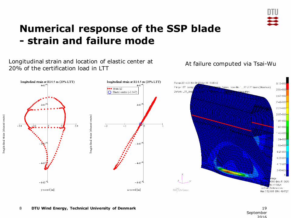
Numerical response of the SSP blade- strain and failure mode
8 19 September
2016
At failure computed via Tsai-Wu Longitudinal strain and location of elastic center at 20% of the certification load in LTT
DTU Wind Energy, Technical University of DenmarkAdd Presentation Title in Footer via ”Insert”; ”Header & Footer”
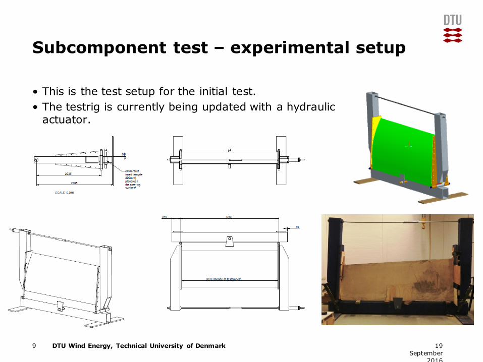
Subcomponent test – experimental setup
• This is the test setup for the initial test.• The testrig is currently being updated with a hydraulic
actuator.
9 19 September
2016
DTU Wind Energy, Technical University of DenmarkAdd Presentation Title in Footer via ”Insert”; ”Header & Footer”
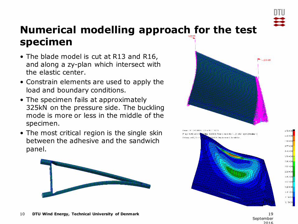
Numerical modelling approach for the test specimen• The blade model is cut at R13 and R16,
and along a zy-plan which intersect with the elastic center.
• Constrain elements are used to apply the load and boundary conditions.
• The specimen fails at approximately 325kN on the pressure side. The buckling mode is more or less in the middle of the specimen.
• The most critical region is the single skin between the adhesive and the sandwich panel.
10 19 September
2016
DTU Wind Energy, Technical University of DenmarkAdd Presentation Title in Footer via ”Insert”; ”Header & Footer”
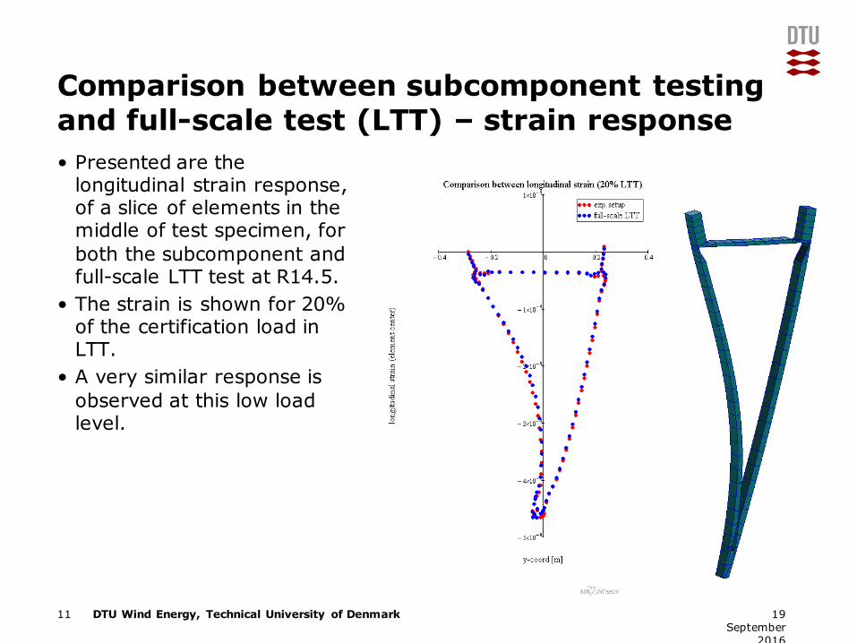
Comparison between subcomponent testing and full-scale test (LTT) – strain response• Presented are the
longitudinal strain response, of a slice of elements in the middle of test specimen, for both the subcomponent and full-scale LTT test at R14.5.
• The strain is shown for 20% of the certification load in LTT.
• A very similar response is observed at this low load level.
11 19 September
2016

DTU Wind Energy, Technical University of DenmarkAdd Presentation Title in Footer via ”Insert”; ”Header & Footer”
Comparison between subcomponent testing and full-scale test (LTT) – strain response• The same comparison but now at different load levels.
12 19 September
2016
DTU Wind Energy, Technical University of DenmarkAdd Presentation Title in Footer via ”Insert”; ”Header & Footer”
Comparison between subcomponent testing and full-scale test (LTT) – failure mode
13 19 September
2016
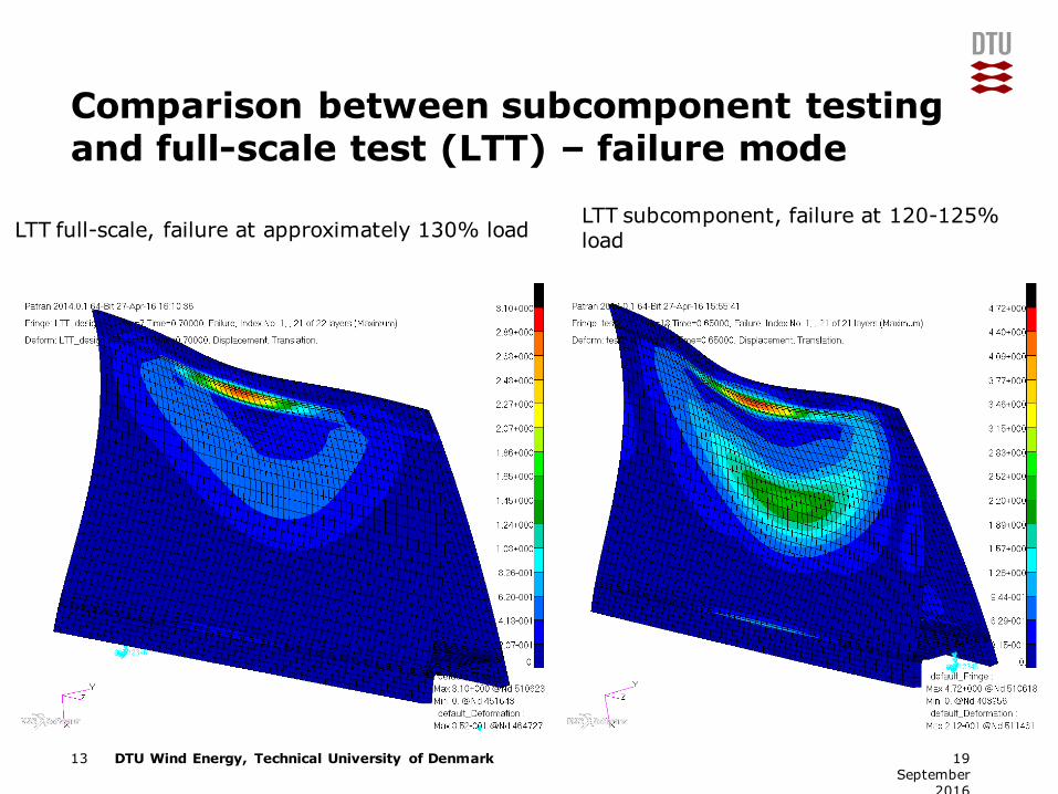
LTT full-scale, failure at approximately 130% loadLTT subcomponent, failure at 120-125% load
DTU Wind Energy, Technical University of DenmarkAdd Presentation Title in Footer via ”Insert”; ”Header & Footer”
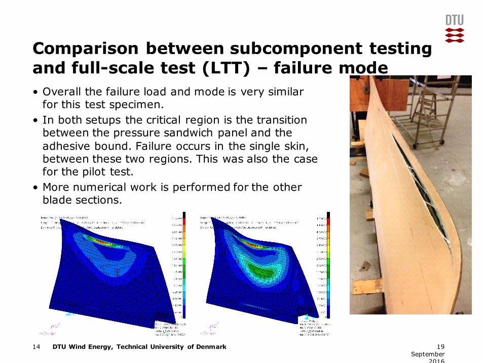
Comparison between subcomponent testing and full-scale test (LTT) – failure mode• Overall the failure load and mode is very similar
for this test specimen. • In both setups the critical region is the transition
between the pressure sandwich panel and the adhesive bound. Failure occurs in the single skin, between these two regions. This was also the case for the pilot test.
• More numerical work is performed for the other blade sections.
14 19 September
2016
DTU Wind Energy, Technical University of DenmarkAdd Presentation Title in Footer via ”Insert”; ”Header & Footer”
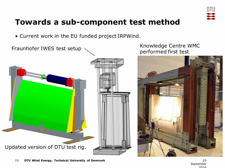
Towards a sub-component test method
• Current work in the EU funded project IRPWind.
15 19 September
2016
Updated version of DTU test rig.
Fraunhofer IWES test setup Knowledge Centre WMC performed first test
DTU Wind Energy, Technical University of DenmarkAdd Presentation Title in Footer via ”Insert”; ”Header & Footer”
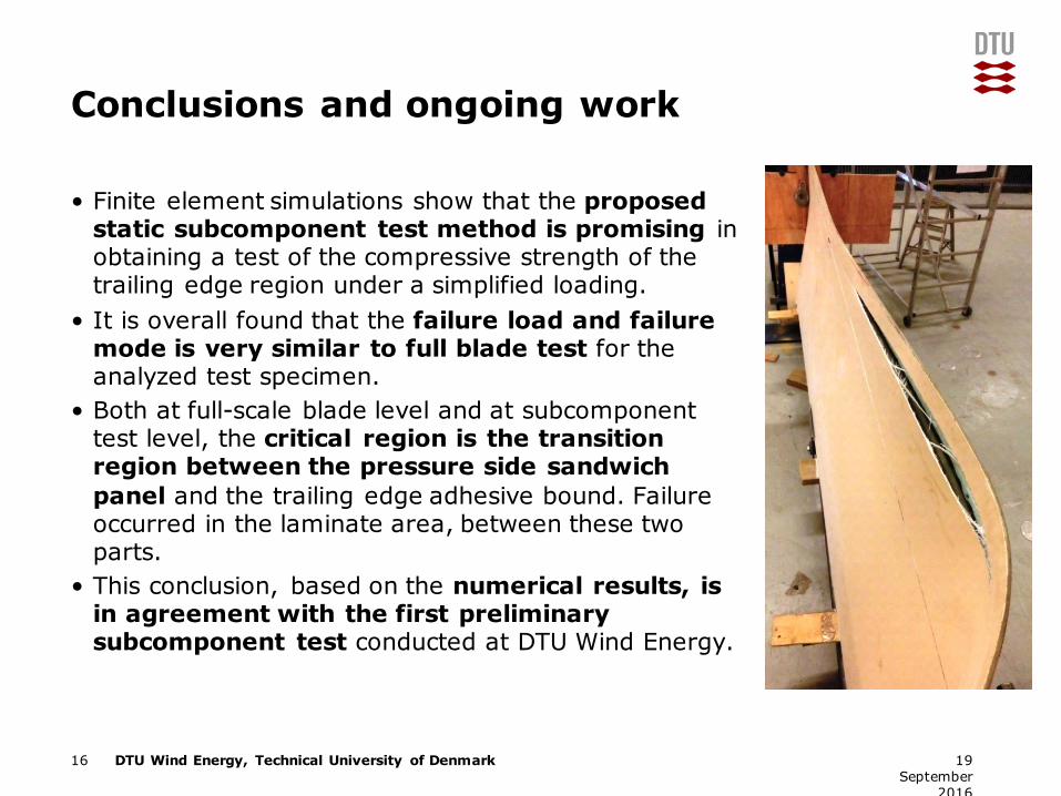
Conclusions and ongoing work
• Finite element simulations show that the proposed static subcomponent test method is promising in obtaining a test of the compressive strength of the trailing edge region under a simplified loading.
• It is overall found that the failure load and failure mode is very similar to full blade test for the analyzed test specimen.
• Both at full-scale blade level and at subcomponent test level, the critical region is the transition region between the pressure side sandwich panel and the trailing edge adhesive bound. Failure occurred in the laminate area, between these two parts.
• This conclusion, based on the numerical results, is in agreement with the first preliminary subcomponent test conducted at DTU Wind Energy.
16 19 September
2016

The work is funded by:
European Community’s Seventh Framework Programmed under funding scheme: Combination of CP & CSA with grant agreement No. 609795 (IRPWIND)
Danish Energy Agency through the Energy Technology Development and Demonstration Program (EUDP 2010), grant no. 64011-0006. The supported project is named Experimental Blade Research Phase 2 (EBR2)
Special thanks to SSP Technology A/S for providing blades for testing as part of the EBR2 project
Any questions?