topping unit process flow diagram
DESCRIPTION
Referential PFD of 10.000 BPDTRANSCRIPT

BTC CRUDE OIL PIPELINE
CRUDE TOPPING UNITS
Process and Equipment Description
Prepared by: Hamid Habib BTC System Process Engineer Mobile: +99450 225 4275
Draft Version 2/16 March 2008
Email: [email protected]
TABLE OF CONTENTS:
Page # A. Main Components -3 B. Process Description -4 C. Equipment Description -5 D. Process Design Basis -5 E. Utilities Summary -5 F. CTU Control System Issue -9 G. List of Spare Parts Ordered -6 H. Process Flow Diagram -9 I. Equipment and Plant Photos -10

Draft Version 3/16 March 2008
A. Main Components
# Equipment Name Tag Number 1. Feed Crude/Cold Residue Heat Exchangers X27901/27913 2. Feed Crude/Topped Crude Heat Exchangers X27902/27903 3. Feed Crude/Intermediate Residue Heat Exchanger X27904 4. Feed Crude/Hot Residue Heat Exchanger X27905 5. Crude Heater B27906 6. Crude Tower V27907 7. Topped Crude Stripped Reboiler X27917 8. Residue Pumps P27918/19 9. Topped Crude Stripper V27908 10. Topped Crude Pumps P27915/16 11. Crude Tower Overhead Condenser X27909 12. Crude Tower Reflux drum V27910 13. Closed Drain Pumps P27932/33 14. Crude Tower Reflux Pumps P27911/12 15. Filming Amine Pumps P27927/28 16. Neutralizing Amine Pumps P27929/30 17. Closed Drain Tank V27931 18. Topped Crude Product Cooler X27921 19. Residue Cooler X27920 20. Offgas Knock Out Drum V27922 21. Flare Knock Out Drum V27923 22. Flare Knock Out Drum Pumps P27924/25 23. Flare Stack M27926 24. Offgas Preheater X27937 25. Atomizing Air Compressors C27934/35 26. Atomizing Air Receiver V27936
Draft Version 4/16 March 2008
B. Process Description The CTU Unit (Vendor Name: SPIE Capag Petrofac International LTD; Home Office:
Petrofac House, Al Soor Street P.O. Box 23467, Sharjah U.A.E.; Tel: +971 6 5740999; Fax; +971 6 5740099) is designed to produce 290 net m3/day of distillate products from 1002 m3/day of 34.6o API crude oil feedstock. In normal operation it is needed 2 operation technicians and 1 Control Room Technician to control/operate the whole system.
Incoming crude oil exchangers heat with residue in X27901/X27913 Crude/Cold Residue Exchangers. The crude temperature leaving this exchanger set is approximately 93 o C. The crude oil then flows to X27902/X27903 Crude/Topped Crude Exchangers where it exchanges heat with the topped crude product. The crude temperature leaving this exchanger set is approximately 149 o C. The crude oil then flows to X27904 Crude/Intermediate Residue Exchanger where it exchanges heat with the intermediate residue. The crude temperature leaving this exchanger is approximately 177 o C. The crude then flows X27905 Crude/Hot Residue where it exchanges heat with the hot residue. The crude temperature leaving this exchanger is approximately 204 o C. The crude then flows through the feed control valve and into B27906 Crude Feed Heater. Here the crude is heated to 332 o C to partially vaporize the crude before entering the flash zone of V27907 Crude Tower. The heater is normally fired by distillate from the process (external supply of distillate is required during start-up) using air atomization. The total crude charge is controlled by flow control to the Crude Heater. The crude heater outlet temperature is controlled by a temperature controller, which adjusts the topped crude to the heater burners. The atomizing air pressure is maintained by sensing and controlling the differential pressure between the topped crude fuel and the air. The partially vaporized crude is fed to Crude Tower, V27907, below Tray (bottom tray). The vaporized portion of the crude rises through the upper trays of V27907 and contacts descending liquid reflux to achieve the required fractionation. The overhead vapor stream is cooled and condensed to 52o C in the Crude Tower Overhead Condenser, X27909. Any excess non-condensed vapors are discharged by pressure control to V27922 Off-gas Knockout Drum and then to the off-gas burners in the crude heater. When the ambient temperature is low, hot vapor can be bypassed around X27909 in order to maintain a positive pressure on the Crude Tower Reflux Drum. The condensed overhead naphtha product is collected in the Crude Tower Reflux Drum, V27910. Naphtha is pumped back to the top of crude tower to provide reflux by the Naphtha Reflux/Product Pumps, P27911/27912. The rate is controlled to maintain a Crude Tower Top temperature of 122 o C. These pumps also pump Naphtha product from V27910 on level control to blend with the residue before final cooling and rundown to storage. Water vapor in the overhead stream will also be condensed in X27909 and will settle to the boot in V27910. The water collected in the boot of V27910 is level controlled to V27931 Closed Drain Tank. It is then pumped from V27931 by P7932/27933 to be mixed with the naphtha/residue stream downstream of X27920 Residue cooler. Raw topped crude is drawn from a chimney tray between tray 10 and 11 of V27907 and fed above tray number 1 of the Topped Crude Stripper, V27908. The draw temperature is approximately 207o C. The topped Crude flows from the bottom of V27908 into the suction of P27915/27916 where a portion of the topped crude is pumped through the tubeside of the topped Crude Stripper

Draft Version 5/16 March 2008
Reboiler, X27917, where heat is added to the topped crude from the hot residue. The liquid and vapor from X27917 Topped Crude Stripper Reboiler returns back to the Topped Crude Stripper, V27908 below tray 6. The vapor from V27908 flows back to V27907 between trays 9 and 10. The balance of the topped crude is pumped through X27902/27903 and the flow splits after the exchangers. The reflux flows back to V27907 and goes in below the chimney tray and is flow controlled. The topped crude product then flows to X27921 Topped Crude Product Cooler, where it is cooled to approximately 54o C and then to the product storage.
Residue, the bottom product from Crude Tower, V27907, flows into a tree-way valve where the flow splits and a portion of the residue flows to the shellside of X27917 Topped Crude Stripper Reboiler and the balance joins the flow from X27917 and flows to the shellside of X27905 exchanger and then to the suction of the Residue Pumps, P27918/19. Since the crude charge contains H2S, sulfur and salt, special provisions have been made in the design to handle these problem corrosion areas. Special metallurgy has been used in some locations. Also, provisions have been made to inject filming and neutralizing amines to further address these potential problems. For details on operation and care of the equipment and packages contained within the system refer to the manufacturer’s instructions. The manufacturer’s instructions for operation of the equipment contained must be understood before attempting to start-up the system.
C. Equipment Description
1. Feed Crude/Cold Residue Heat Exchangers (X27901/27913)
The purpose of these exchangers is to exchange heat between the outgoing cold residue and the incoming cold crude. These exchangers have a shellside design of 16.5 barg/1barg (ext) @3710 C and a tubeside design of 20.69 barg @3160 C. The combined duty of both exchangers is 5.163 MMkJ/hr.
2. Feed Crude/Topped Crude Exchangers (X27902/27903) The purpose of these exchangers is to exchange heat between the incoming cold feed crude and the topped crude. These exchangers have a shellside design of 16.5 barg/1barg (ext) @3710 C and a tubeside design of 20.69 barg @3160 C. The combined duty of both exchangers is 6.0163 MMkJ/hr.
3. Feed Crude/Intermediate Residue Exchanger (X27904)
The purpose of this exchanger is to exchange heat between the outgoing intermediate residue and the incoming crude. This exchanger has a shellside design of 16.5 barg/1barg (ext) @3710 C and a tubeside design of 20.69 barg @3160 C. The duty of the exchanger is 3.9096 MMkJ/hr.
4. Feed Crude/Hot Residue Exchanger (X27905) The purpose of this exchanger is to exchange heat between the outgoing hot residue and the incoming crude. This exchanger has a shellside design of 16.5 barg/1barg (ext) @3710
C and a tubeside design of 20.69 barg @3160 C. The duty of the exchanger is 5.642 MMkJ/hr.

Draft Version 6/16 March 2008
5. Feed Crude Heater (B27906) The crude heater is designed to raise the incoming crude temperature from 2040 C to 3320
C. The heater is a one-pass design with a convection section. The heater has a high outlet temperature alarm and shutdown. The heater also has high stack temperature alarms and shutdown and low flow alarms and shutdowns. Heater design is 16.6 barg @3990 C and the duty is 20.94 MMkJ/hr.
6. Crude Tower (V27907)
The crude tower is 1524 mm ID x 15850 mm S/S with a design of 5.2 barg/1barg (ext) @3710 C. The tower has a total of 18 trays and 1 chimney tray. The chimney tray is located between tray 10 and tray 11 with tray 1 being the top tray and tray 18 being the bottom tray. Naphtha reflux is fed back to the crude tower on tray 1 and topped crude reflux is fed back to the crude tower tray on tray 11. The residue flows from the bottom of the tower to the various exchangers in the preheat exchanger train before it is mixed with the naphtha for final cooling and storage.
7. Topped Crude Stripper Reboiler (X27917)
The purpose of this exchanger is to provide heat between for the topped crude stripper. This is accomplished by utilizing the heat of the residue to reboil the topped crude. This exchanger has a shellside design of 16.5 barg/1barg (ext) @3710 C and a tubeside design of 20.69 barg @3160 C. Topped crude enters the tubeside from the Topped Crude Pumps and flows through the tube bundle, and back into the stripper.
8. Residue Pumps (P27918/P27919)
The purpose of the Residue Pumps is to pump the residue from the crude tower through the heat exchanger train and then to storage. These pumps are designed to pump approximately 34.6 m3/hr of residue @7.5 bar differential. These pumps are driven by 22 kW electric motors.
9. Topped Crude Stripper (V27908) The Topped Crude Stripper is a vertical tower designed to improve the flash point of the topped crude product by stripping off lighter components. The stripper is 762 mm ID x 8534 mm S/S and a design of 5.2 barg/1barg (ext). The stripper contains 6 valve trays. The feed to the stripper is drawn from the chimney tray and enters the stripper on tray #1, which is the top tray. Topped Crude is pumped from the bottom of the stripper through the topped crude reboiler and back.
10. Topped Crude Pumps (P27915/P27916) The Topped Crude Pumps are designed to pump approximately 58.8 m3/hr of topped crude at a pressure differential of 5.3 bar. Approximately 5.41 m3/hr is used for reflux and the balance flows to the topped crude product cooler. The pumps are driven with 18.5 kW electric motors.
11. Crude Tower Overhead Condenser (X27909) The purpose of this exchanger is to cool and condense the overhead vapor from the crude tower. The design conditions for this exchanger are 5.2 barg/1barg (ext) @1770 C. The design duty is 13.371 MMkJ/hr. This exchanger is designed with a warm air recirculation system to reduce or prevent freezing of the condensed water.
12. Crude Tower Reflux Drum (V27910)
Draft Version 7/16 March 2008
The Crude Tower Reflux Drum is a horizontal vessel 1219 mm ID x 3048 mm S/S with a 610 mm OD x 762 mm S/S Monel 400 boot. The design pressure is 5.2 barg/1barg (ext) @1770 C. The purpose of the Crude Tower Reflux Drum is to accumulate the overhead naphtha product, some of which is used for reflux, with the balance being pumped back to blend with the residue. The condensed water is separated from the naphtha in the accumulator and flows into the accumulator boot where it is level controlled to the Closed Drain Tank. This water is pumped back to the naphtha/residue rundown line after the residue cooler.
13. Closed Drain Pumps (P27932/P27933)
The Closed Drain Pumps are centrifugal sump pumps designed to pump approximately 28.4 m3/hr of produced water to a differential pressure of 3.25 bar. These pumps are driven by 11 kW electric motors.
14. Crude Tower Reflux Pumps (P27932/P27933) The naphtha reflux/product pumps designed to pump approximately 41.2 m3/hr of naphtha overhead product. Naphtha is used as a reflux to the crude tower with the excess being sent back to blend with the residue. These pumps have a design differential pressure of 4.28 bar and are driven by 11 kW electric motors.
15. Filming Amine Pumps (P27927/P27928) These pumps are oil actuated diaphragm injection pumps designed specifically for low rate injections of specialty chemicals into process. Each motor has one pump unit, which is adjustable from 0% to 100% design capacity. The electric motors are 0.18 kW. These pumps supply filming amine to the crude tower overhead line at a maximum rate of 5lt/hr @5.13 barg.
16. Neutralizing Amine Pumps (P27929/P27930) These pumps are oil actuated diaphragm injection pumps designed specifically for low rate injections of specialty chemicals into process. Each motor has one pump unit, which is adjustable from 0% to 100% design capacity. The electric motors are 0.18 kW. These pumps supply neutralizing amine to the crude tower overhead line at a maximum rate of 5lt/hr @5.13 barg.
17. Closed Drain Tank (V27931) The Closed Drain Tank is a horizontal vessel 1524 mm ID x 4877 mm S/S with a 2610 mm OD x 152 mm long boots. The design pressure is 3.44 barg/1barg (ext) @3150 C. The purpose of this vessel to contain any blowdown or drain from instruments, etc to prevent hydrocarbon emissions.
18. Topped Crude Product Cooler (X27921) This exchanger takes the topped crude product from X27902/27903 and cools the product down to 540 C before the product flows to storage. The tubeside design is 16.5 barg/1barg (ext) @1600 C. The duty is 1.519 MMkJ/hr. This exchanger shares a common frame and fans with X27920. This exchanger is designed with a warm air recirculation system to reduce or prevent freezing of the cooled fluid.
19. Residue Cooler (X27920) This exchanger takes the naphtha/residue blend cools it to 540 C before the mix flows to storage. The tubeside design is 16.5 barg/1barg (ext) @1600 C. The exchanger duty is

Draft Version 8/16 March 2008
5.376 MMkJ/hr. This exchanger shares a common frame and fans with X27921. This exchanger is designed with a warm air recirculation system to reduce or prevent freezing of the cooled fluid. Fans are driven by 2-11 kW motors.
20. Offgas KO Drum (V27922) This vessel is designed to separate the offgas from any entrained liquid before the offgas gas enters the burners. This vessel is 457 mm OD x 2133 mm S/FF and designed for 5.2 barg/1barg (ext) @1200 C. This vessel also contains a mist eliminator.
21. Flare KO Drum (V27923) This is a horizontal vessel and designed to remove the entrained liquids from the gas flowing to the flare. This vessel is 1524 mm ID x 3048 mm S/S and designed for 5.2 barg/1barg (ext) @2600 C. The liquid is pumped from the Flare KO Drum and into the naphtha/residue mix downstream from X27920.
22. Flare KO Drum Pumps (P27924/P27925) The Flare Knockout Drum Pumps are designed to pump 11.4 m3/hr at a differential pressure of 4.4 bar. The pumps are driven by 7.5 kW electric motors. The discharge of these pumps flow into the naphtha/residue mix downstream of X27920.
23. Flare (M27926)
The Flare Stack is 324 mm OD x 15240 mm high. It is designed to flare the emergency venting from the relief valves in the CTU. The ignition of the flare is generated by a continuous sparking system with an adjustable time lapse for the spark.
24. Offgas Preheater (X27937) The Offgas Preheater is a 10 kW electric heater designed to heat the offgas to 125-1270 C before entering the burners. This will vaporize any condensed liquids and prevent coking of the burners.
25. Atomizing Air Compressors (C27934/C27935) The Air Compressors are oil immersed rotary screw compressors capable of compressing 161 NCMH of air @ 6.9 barg. The compressors discharge into V27936 Atomizing Air Receiver and from there to the heater burners.
26. Atomizing Air Receiver (V27936)
The Atomizing Air Receiver is a vertical vessel with dimensions of 914 mm ID x 2438 mm S/S and designed for 12.07 barg @ 1490 C.

Draft Version 9/16 March 2008
D. Process Design Basis
Some of the crudes included in the blends did not have specific pour/cloud point data in the assays. Petrofac had to assume that the pour/cloud point values would have the same relative values as those given in the assays. The given data indicated the pour/cloud points to be within 1 or 2o C. The cloud point is an estimated value inferred by the calculated pour point. In the simulations of the blends, Petrofac allowed a margin of 5o C for the correlation of cloud point to pour point. As an example, the simulation was set up to make the topped crude pour point -35o C. From this point, Petrofac assumed that this would meet the -30o C cloud point. Below is a brief discussion of each of the blends for a specific feed rate. Since the cloud points are correlated with the predicted pour point, then some error may exist which will require a small yield adjustment. This will require an adjustment to the feed rate to maintain the correct product quantity. Azeri Blend 1 The Azeri Blend 1 simulation predicts a gross yield of 1919 bbl/day with a feed rate of 4800 bbl/day. The pour was adjusted using the 90% distillation point and the point used is 332o C. This setting predicted a pour point of -35.2o C. This is 5.2o C colder than the required specification of -30o C cloud point. The predicted offgas production will be produce approximately 116% of the required duty for the Crude Heater. This may require some flaring of the excess gas. Azeri Blend 2 The Azeri Blend 2 simulation predicts a gross yield of 1492 bbl/day with a feed rate of 5000 bbl/day. The pour point was adjusted using the 90% distillation point and the point used is 332o C. This setting predicted a pour point of -34.5o C. This is 4.5o C colder than the required specification of -30o C cloud point. The predicted offgas production will be produce approximately 84% of the required duty for the Crude Heater. Caspian Blend 1 The Caspian Blend 1 simulation predicts a gross yield of 1941 bbl/day with a feed rate of 4900 bbl/day. The pour point was adjusted using the 90% distillation point and the point used is 332o C. This setting predicted a pour point of -35.5o C. This is 5.5o C colder than the required specification of -30o C cloud point. The predicted offgas production will be produce approximately 139% of the required duty for the Crude Heater. This may require some flaring of the excess gas. Caspian Blend 2 The Caspian Blend 2 simulation predicts a gross yield of 1935 bbl/day with a feed rate of 5000 bbl/day. The pour point was adjusted using the 90% distillation point and the point used is 332o C. This setting predicted a pour point of -34.9o C. This is 4.9o C colder than the required specification of -30o C cloud point. The predicted offgas production will be produce approximately 110% of the required duty for the Crude Heater. This may require some flaring of the excess gas.
Draft Version 10/16 March 2008
Azeri GCA-6Y (Base Case) The Azeri GCA-6Y simulation predicts a gross yield of 1920 bbl/day (290 m3/day) with a feed rate of 6303 bbl/day (1002 m3/day). The pour point was adjusted using the 90% distillation point and the point used is 304o C. This setting predicted a pour point of -35.6o C. This is 5.6o C colder than the required specification of -30o C cloud point. The predicted offgas production will be produce approximately 11% of the required duty for the Crude Heater. ACG Chirag The ACG Chirag crude simulation predicts a gross yield of 1937 bbl/day (307.9 m3/day) with a feed rate of 5303 bbl/day (843.2 m3/day). The pour point was adjusted using the 90% distillation point and the point used is 315.5o C. This setting predicted a pour point of -36.76o C. This is 6.76o C colder than the required specification of -30o C cloud point. The predicted offgas production will be produce approximately 51% of the required duty for the Crude Heater. Each simulations indicate that the designed unit is capable of running the ACG Chirag Crude, the Azeri GCA-6Y Crude, and each of the four blends (Azeri Blends 1&2, Caspian Blends 1&2) and meet the required production level. The exact cloud points for each product stream will have to be determined by lab analysis. At this point, we can then make adjustments to the plant that should enable it to make the cloud point specification. Since the major pieces of equipment have a 25% design margin, Petrofac can foresee no problems making the required volume of topped crude. Operating Parameters and Acceptable Deviations The operating parameters for the plant are numerous. These will be covered in the start up and operating manual. Each of the different crude feeds will have a different set of operating parameters and deviations. Process Guarantees The Crude Topping Unit shall be guaranteed to produce topped crude with a total lower heating content of 117 MW for 100% ACG Chirag, 100% Azeri Blends 1&2 and Caspian Blend 1&2, after deducting the fuel requirement for the fired heater. For all the above specified feeds, the unit should be able to operate continuously at 35% turndown whilst meeting the distillate specifications. Environmental Deviations The major environmental deviation expected is constant flaring of offgas generated by some of the crude blends. Per Petrofac’s heater vendor, providing more than 45% of the heater duty requirement with the offgas may reduce the burner ability to meet the NOx emission regulations. There are some operating parameters that can be changed to reduce the amount of offgas generated. These will be covered in the Start-up and Operating Manual.
Draft Version 11/16 March 2008
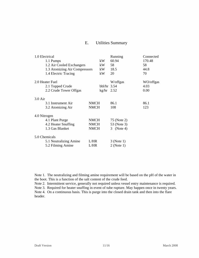
E. Utilities Summary
1.0 Electrical Running Connected
1.1 Pumps kW 60.94 170.48 1.2 Air Cooled Exchangers kW 58 58
1.3 Atomizing Air Compressors kW 18.5 44.8 1.4 Electric Tracing kW 20 70 2.0 Heater Fuel W/offgas WO/offgas 2.1 Topped Crude bbl/hr 3.54 4.03 2.2 Crude Tower Offgas kg/hr 2.52 0.00 3.0 Air 3.1 Instrument Air NMCH 86.1 86.1 3.2 Atomizing Air NMCH 108 123 4.0 Nitrogen 4.1 Plant Purge NMCH 75 (Note 2) 4.2 Heater Snuffing NMCH 53 (Note 3) 1.3 Gas Blanket NMCH 3 (Note 4) 5.0 Chemicals 5.1 Neutralizing Amine L/HR 3 (Note 1) 5.2 Filming Amine L/HR 2 (Note 1)
Note 1. The neutralizing and filming amine requirement will be based on the pH of the water in the boot. This is a function of the salt content of the crude feed. Note 2. Intermittent service, generally not required unless vessel entry maintenance is required. Note 3. Required for heater snuffing in event of tube rupture. May happen once in twenty years. Note 4. On a continuous basis. This is purge into the closed drain tank and then into the flare header.

Draft Version 12/16 March 2008
F. CTU Control System Issue
The overriding highlight is that the CTU will effectively become inoperable once disconnected from the ICSS (Integrated Control and Safety System for the BTC pipeline). ABB or another vendor (see below) would need to rebuild a control and safety system. It would be easier for ABB who can “cut & paste” the software into a new control system. Another vendor would be starting from scratch. There is no doubt that another vendor would be cheaper. If it was decided that another vendor should be considered then it might need to discuss with ABB, to release of their proprietary code and that is code which only works with ABB’s operating system. So that as a vendor ABB is a realistic option. For information, the CTU local panel will remain but this is simply an interface to the ICSS and local controls do not function without the ICSS. Rather than saying what will work, it is easier to list what will not work once disconnected from the ICSS and without a replacement control system: 1. Remote starting of pumps and fans will not be available, pumps and fans will need to be started at the pumps themselves. 2. No Duty/Standby control will be available 3. Automatic gap control will not be available 4. ESD protection will not be available. 5. Fire and Gas protection will not be available. 6. PID control will not be available 7. Alarm & Eventing will not be available 8. All motor operated valves will need to be operated locally at the valve. 9. ESDV's will not be available and will be in their failsafe position. 10 Burner startup sequence will be completely manual without safety interlocks (if possible at all). 11. Flame out detection will not be available 12 Burner ignition will not be available. 13. Indications to local control panel will not work. 14. Pushbuttons on local control panel will not function. There will be no operator interface and the operational safety would need serious consideration.
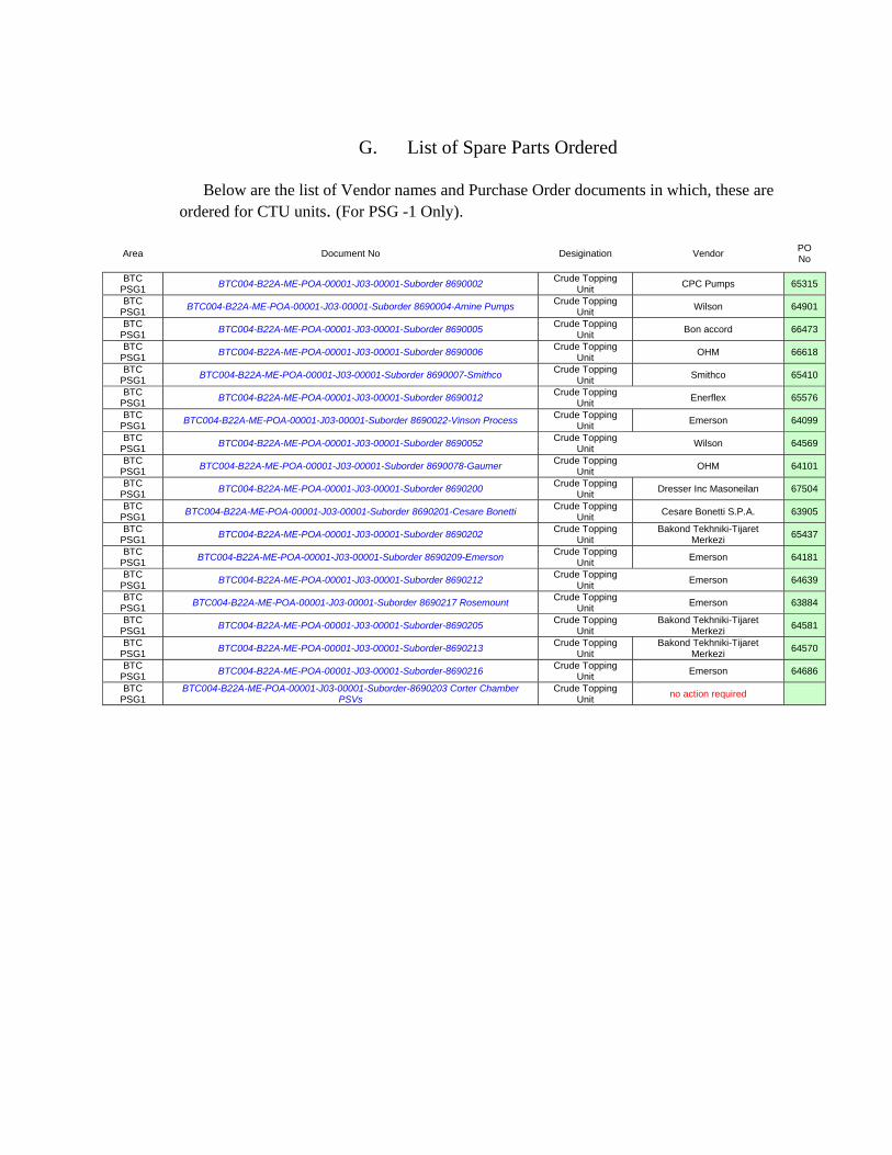
G. List of Spare Parts Ordered
Below are the list of Vendor names and Purchase Order documents in which, these are ordered for CTU units. (For PSG -1 Only).
Area Document No Desigination Vendor PO No
BTC PSG1
BTC004-B22A-ME-POA-00001-J03-00001-Suborder 8690002 Crude Topping
Unit CPC Pumps 65315
BTC PSG1
BTC004-B22A-ME-POA-00001-J03-00001-Suborder 8690004-Amine Pumps Crude Topping
Unit Wilson 64901
BTC PSG1
BTC004-B22A-ME-POA-00001-J03-00001-Suborder 8690005 Crude Topping
Unit Bon accord 66473
BTC PSG1
BTC004-B22A-ME-POA-00001-J03-00001-Suborder 8690006 Crude Topping
Unit OHM 66618
BTC PSG1
BTC004-B22A-ME-POA-00001-J03-00001-Suborder 8690007-Smithco Crude Topping
Unit Smithco 65410
BTC PSG1
BTC004-B22A-ME-POA-00001-J03-00001-Suborder 8690012 Crude Topping
Unit Enerflex 65576
BTC PSG1
BTC004-B22A-ME-POA-00001-J03-00001-Suborder 8690022-Vinson Process Crude Topping
Unit Emerson 64099
BTC PSG1
BTC004-B22A-ME-POA-00001-J03-00001-Suborder 8690052 Crude Topping
Unit Wilson 64569
BTC PSG1
BTC004-B22A-ME-POA-00001-J03-00001-Suborder 8690078-Gaumer Crude Topping
Unit OHM 64101
BTC PSG1
BTC004-B22A-ME-POA-00001-J03-00001-Suborder 8690200 Crude Topping
Unit Dresser Inc Masoneilan 67504
BTC PSG1
BTC004-B22A-ME-POA-00001-J03-00001-Suborder 8690201-Cesare Bonetti Crude Topping
Unit Cesare Bonetti S.P.A. 63905
BTC PSG1
BTC004-B22A-ME-POA-00001-J03-00001-Suborder 8690202 Crude Topping
Unit Bakond Tekhniki-Tijaret
Merkezi 65437
BTC PSG1
BTC004-B22A-ME-POA-00001-J03-00001-Suborder 8690209-Emerson Crude Topping
Unit Emerson 64181
BTC PSG1
BTC004-B22A-ME-POA-00001-J03-00001-Suborder 8690212 Crude Topping
Unit Emerson 64639
BTC PSG1
BTC004-B22A-ME-POA-00001-J03-00001-Suborder 8690217 Rosemount Crude Topping
Unit Emerson 63884
BTC PSG1
BTC004-B22A-ME-POA-00001-J03-00001-Suborder-8690205 Crude Topping
Unit Bakond Tekhniki-Tijaret
Merkezi 64581
BTC PSG1
BTC004-B22A-ME-POA-00001-J03-00001-Suborder-8690213 Crude Topping
Unit Bakond Tekhniki-Tijaret
Merkezi 64570
BTC PSG1
BTC004-B22A-ME-POA-00001-J03-00001-Suborder-8690216 Crude Topping
Unit Emerson 64686
BTC PSG1
BTC004-B22A-ME-POA-00001-J03-00001-Suborder-8690203 Corter Chamber PSVs
Crude Topping Unit
no action required

H. Process Flow Diagram

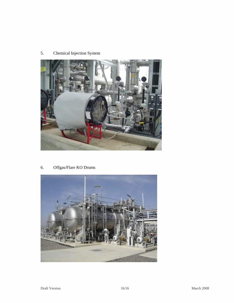
I. Equipment and Plant Photos
1. CTU General Panorama
2. CTU General Panorama from other side 3. Crude Topping Heater 4. Flare Stack 4. Flare Stack
Draft Version 16/16 March 2008
5. Chemical Injection System 6. Offgas/Flare KO Drums